WO2018190288A1 - 雌端子 - Google Patents
雌端子 Download PDFInfo
- Publication number
- WO2018190288A1 WO2018190288A1 PCT/JP2018/014879 JP2018014879W WO2018190288A1 WO 2018190288 A1 WO2018190288 A1 WO 2018190288A1 JP 2018014879 W JP2018014879 W JP 2018014879W WO 2018190288 A1 WO2018190288 A1 WO 2018190288A1
- Authority
- WO
- WIPO (PCT)
- Prior art keywords
- contact pressure
- contact
- male terminal
- pressure applying
- terminal
- Prior art date
Links
Images


Classifications
-
- H—ELECTRICITY
- H01—ELECTRIC ELEMENTS
- H01R—ELECTRICALLY-CONDUCTIVE CONNECTIONS; STRUCTURAL ASSOCIATIONS OF A PLURALITY OF MUTUALLY-INSULATED ELECTRICAL CONNECTING ELEMENTS; COUPLING DEVICES; CURRENT COLLECTORS
- H01R13/00—Details of coupling devices of the kinds covered by groups H01R12/70 or H01R24/00 - H01R33/00
- H01R13/02—Contact members
- H01R13/10—Sockets for co-operation with pins or blades
- H01R13/11—Resilient sockets
- H01R13/115—U-shaped sockets having inwardly bent legs, e.g. spade type
-
- H—ELECTRICITY
- H01—ELECTRIC ELEMENTS
- H01R—ELECTRICALLY-CONDUCTIVE CONNECTIONS; STRUCTURAL ASSOCIATIONS OF A PLURALITY OF MUTUALLY-INSULATED ELECTRICAL CONNECTING ELEMENTS; COUPLING DEVICES; CURRENT COLLECTORS
- H01R13/00—Details of coupling devices of the kinds covered by groups H01R12/70 or H01R24/00 - H01R33/00
- H01R13/02—Contact members
- H01R13/10—Sockets for co-operation with pins or blades
- H01R13/11—Resilient sockets
- H01R13/113—Resilient sockets co-operating with pins or blades having a rectangular transverse section
Definitions
- the technology disclosed in this specification relates to a female terminal.
- a female terminal described in Japanese Patent Application Laid-Open No. 2014-53205 (Patent Document 1 below) is known.
- This female terminal is made by pressing and bending a sheet metal. Further, the processed female terminal is plated.
- the female terminal has a rectangular tubular box part into which the male tab terminal is inserted, and a conductor crimping part to which the conductor of the electric wire is crimped on the rear side of the box part.
- a leaf spring and a tab receiving portion are provided inside the box portion.
- the leaf spring is provided on the upper wall inside the box portion and elastically contacts the male tab terminal.
- the tab receiving portion is provided on the lower wall inside the box portion and comes into contact with the male tab terminal.
- the male tab terminal is made by pressing and bending a sheet metal. Further, the processed male tab terminal is plated.
- the male tab terminal has a male-side main body that forms a rod shape.
- the male side main body part When the male side main body part is inserted into the box part of the female terminal, the male side main body part is sandwiched between the leaf spring and the tab receiving part. Thereby, a male tab terminal and a female terminal contact elastically, and are electrically connected.
- the male side main body part of the male tab terminal is inserted while being elastically pressed against the leaf spring inside the box part, so the contact part between the male tab terminal and the female terminal Then, the plating applied to the female terminal is worn.
- plating wear increases. In order to prevent such plating wear, it is generally necessary to reduce the contact pressure of the leaf spring of the female terminal.
- the contact pressure of the leaf spring of the female terminal is lowered, the connection reliability between the terminals is lowered, and there is a problem that a connection failure between the terminals easily occurs due to vibration or the like.
- a female terminal disclosed in the present specification is a female terminal fitted to a male terminal, and has a ceiling wall and a bottom wall facing in the vertical direction, and the male terminal is inserted and opened in the front-rear direction.
- a pressure application unit, and a second contact pressure application unit that is provided at a position facing the first contact pressure application unit in the vertical direction and that contacts the male terminal from the bottom wall side to apply contact pressure,
- the first contact portion where the first contact pressure applying portion and the male terminal are in contact with each other, and the second contact portion where the second contact pressure applying portion and the male terminal are in contact with each other are shifted in the front-rear direction.
- the contact pressure applied to the male terminal by the first contact pressure applying unit is the contact pressure applied to the male terminal by the second contact pressure applying unit. It is lower.
- the contact pressure applied to the male terminal by the second contact pressure applying portion from the bottom wall side inside the female side main body portion is set as a high contact pressure, and the ceiling wall side inside the female side main body portion is set.
- the contact pressure applied to the male terminal by the first contact pressure applying unit can be set to a low contact pressure.
- the high contact pressure is a contact pressure at which electrical connection is not interrupted at the contact portion between the female terminal and the male terminal when vibration or the like is applied to the fitted male terminal and female terminal. .
- the low contact pressure is a contact pressure lower than the high contact pressure. Even when the male terminal is inserted into and removed from the female terminal, the plating applied to the female terminal does not wear at the contact portion between the male terminal and the female terminal. The contact pressure is about. By doing in this way, the plating applied to the female terminal will be worn at the second contact part where the second contact pressure applying part of high contact pressure and the male terminal are in contact with each other. It becomes difficult to receive, and it becomes difficult to produce the connection failure between both male and female terminals. On the other hand, in the first contact portion where the low contact pressure first contact pressure applying portion and the male terminal are in contact with each other, the wear of the plating applied to the female terminal can be prevented.
- the second contact pressure applying portion having a high contact pressure allows the plating to be worn while ensuring the connection reliability between the terminals, and the first contact pressure applying portion having a low contact pressure prevents the plating from being worn. Continuity is also ensured by multiple insertion / extraction of male terminals to / from female terminals.
- two said 1st contact pressure provision parts and said 2nd contact pressure provision parts are distribute
- a third contact pressure applying portion that contacts the male terminal from the ceiling wall side to apply a contact pressure, and is provided at a position facing the third contact pressure applying portion in the vertical direction.
- a fourth contact pressure applying portion that contacts from the bottom wall side and applies a contact pressure; a third contact portion that contacts the third contact pressure applying portion and the male terminal; and the fourth contact pressure applying portion.
- the fourth contact portion in contact with the male terminal are arranged to be displaced in the front-rear direction, and the contact pressure applied to the male terminal by the third contact pressure applying portion is the fourth contact pressure applying It may be higher than the contact pressure applied to the male terminal by the portion.
- a high contact pressure is applied to the male terminal from the bottom wall side by the two second contact pressure applying portions, and from the ceiling wall side, the high contact pressure is applied by the one third contact pressure applying portion. Contact pressure will be applied.
- the male terminal in the male housing may be rattled to facilitate the fitting of the male terminal and the female terminal.
- the male terminal When the male terminal is rattling in this way and there is only one pair of the low contact pressure first contact pressure applying portion and the high contact pressure second contact pressure applying portion, When the terminal passes through the second contact portion of the high contact pressure second contact pressure applying portion, the male terminal is displaced to the ceiling wall side by rattling in the male housing, and the first contact pressure with the male terminal is low contact pressure. The application part slides in contact with the contact pressure with a high contact pressure. Thereby, the plating of the first contact pressure applying portion is worn.
- the male terminal can be inserted into and removed from the inside of the female-side main body without the plating of the contact pressure applying portion being worn.
- the second contact pressure applying portion includes a second vertical piece extending vertically from the second contact portion toward the bottom wall, and the end surface of the second vertical piece is inserted into the second vertical piece by the insertion of the male terminal. It is good also as contacting the bottom wall.
- the second contact portion of the second contact pressure applying portion that contacts the male terminal is displaced toward the bottom wall.
- the second vertical piece of the second contact pressure applying portion is also displaced toward the bottom wall, and the end surface of the second vertical piece comes into contact with the bottom wall.
- the second vertical piece extends vertically from the second contact portion toward the bottom wall, it hardly bends. Therefore, when the second vertical piece comes into contact with the bottom wall, the second contact portion is Little displacement towards the bottom wall. Therefore, the second contact pressure applying unit can apply a high contact pressure to the male terminal.
- the third contact pressure applying portion includes a third vertical piece extending vertically from the third contact portion toward the ceiling wall, and insertion of the male terminal causes an end surface of the third vertical piece to be It is good also as contacting a ceiling wall.
- the third contact pressure applying unit can apply a high contact pressure to the male terminal, similarly to the above-described second contact pressure applying unit.
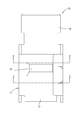
- FIG. BB Front view of female terminal Top view of female terminal Rear view of female terminal AA sectional view in FIG. BB sectional view in FIG. CC sectional view in FIG. DD sectional view in FIG. EE sectional view in FIG.
- the present embodiment will be described with reference to FIGS.
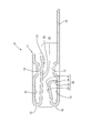
- the female terminal 10 of this embodiment is formed by punching and bending a copper sheet metal. Further, the processed female terminal 10 is plated with silver or the like. As shown in FIG. 1, the female terminal 10 includes a female-side main body 11 and a wire connecting portion 18 provided behind the female-side main body 11. The female terminal 10 is fitted with a male terminal (not shown).
- the male terminal has a plate shape and is formed by punching a sheet metal or the like. Furthermore, the processed male terminal is plated with silver or the like.
- the female main body 11 has a box shape and is open in the front-rear direction.
- the female side main body 11 has a ceiling wall 12 and a bottom wall 15 that face each other in the vertical direction.
- the fitting direction of the female terminal 10 with the male terminal is the front, and the direction from the bottom wall 15 of the female-side main body 11 to the ceiling wall 12 is the upper side.
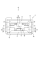
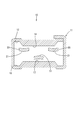
- the ceiling wall 12 includes two first contact pressure applying portions 20 that apply a low contact pressure to the male terminal, and one first contact that applies a high contact pressure to the male terminal. And a three-contact pressure applying unit 40.
- the high contact pressure is a contact pressure at which electrical connection is not interrupted at the contact portion between the female terminal 10 and the male terminal when vibration or the like is applied to the fitted male terminal and female terminal 10. It is. When such a high contact pressure is applied to the male terminal, when the male terminal is inserted into and extracted from the female terminal 10, the plating applied to the contact portion between the male terminal and the female terminal 10 is worn.
- the low contact pressure is a contact pressure lower than the high contact pressure, and the plating applied to the female terminal 10 at the contact portion between the male terminal and the female terminal 10 even if the male terminal is inserted into and removed from the female terminal 10.
- the contact pressure is such that does not wear.
- the two first contact pressure applying portions 20 are connected via a first base end portion 13 having a shape folded from the front end edge of the ceiling wall 12 to the inside of the female side main body portion 11. It is formed to extend rearward.
- the first contact portion 21 is provided on the rear end side of the female-side main body 11 and is formed to protrude downward in an embossed shape inside the female-side main body 11.
- the first contact portion 21 contacts a male terminal (not shown).
- the third contact pressure applying unit 40 is disposed between the two first contact pressure applying units 20 as shown in FIGS. 2 and 6.
- the third contact pressure applying part 40 includes a third contact part 41 that contacts a male terminal (not shown), and a third inclined part 42 that is inclined from the third contact part 41 toward the first base end part 13 on the ceiling wall 12 side. And a third vertical piece 43 extending vertically from the third contact portion 41 toward the ceiling wall 12.
- the third contact portion 41 is provided in front of the first contact portion 21 of the first contact pressure applying portion 20 that applies a low contact pressure.
- the end surface 44 of the third vertical piece 43 and the ceiling wall 12 are not in contact with each other.
- the end surface 44 and the bottom wall 15 are in contact with each other.
- the male terminal is further inserted into the female main body 11 with the end face 44 in contact with the ceiling wall 12, the third vertical piece 43 is held down against the ceiling wall 12 by the male terminal.
- the second contact pressure applying portion 30 is hardly bent. Therefore, the contact pressure applied to the male terminal by the second contact pressure applying unit 30 is a high contact pressure.
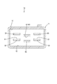
- the bottom wall 15 includes two second contact pressure applying portions 30 that apply a high contact pressure to the male terminal and one first contact that applies a low contact pressure to the male terminal. And a four-contact pressure applying unit 50.
- the two second contact pressure applying portions 30 are provided at positions facing the first contact pressure applying portion 20 in the vertical direction as shown in FIGS. 2, 5, and 7. Further, as shown in FIG. 5, the two second contact pressure applying portions 30 include a second contact portion 31 that contacts a male terminal (not shown), and a second base end portion that extends from the second contact portion 31 to the bottom wall 15. 16 and a second vertical piece 33 extending vertically from the second contact portion 31 toward the ceiling wall 12. The end surface 34 of the second vertical piece 33 and the bottom wall 15 are not in contact with each other, but when a male terminal (not shown) is inserted into the female main body 11, the end surface 34 and the bottom wall 15 are in contact with each other. .
- the second base end portion 16 has a shape that is folded back from the front end edge of the bottom wall 15 to the inside of the female-side main body portion 11.
- the second contact portion 31 is provided in front of a fourth contact portion 51 described later.
- the 2nd contact pressure provision part 30 has comprised the same shape as the 3rd contact pressure provision part 40, and can provide a high contact pressure with respect to a male terminal.
- the fourth contact pressure applying unit 50 is provided at a position facing the third contact pressure applying unit 40 in the vertical direction.
- the fourth contact pressure applying part 50 is formed to extend rearward via the second base end part 16.
- the fourth contact portion 51 is provided on the rear end side of the female-side main body 11 and is formed to protrude upward in an embossed shape inside the female-side main body 11.
- the fourth contact portion 51 contacts a male terminal (not shown).
- a first excessive deflection preventing portion 14 is provided behind the ceiling wall 12 of the female side main body portion 11.
- the first excessive deflection preventing portion 14 is formed by hitting a part of the ceiling wall 12 and extruding inward from the opposite surface of the ceiling wall 12.
- a second excessive deflection preventing portion 17 is provided behind the bottom wall 15 of the female side main body portion 11.
- the second excessive deflection preventing portion 17 is also formed in the same manner as the first excessive deflection preventing portion 14, and prevents the second contact pressure applying portion 30 and the fourth contact pressure applying portion 50 from being excessively bent and plastically deformed. Yes.
- the wire connecting portion 18 is formed to protrude rearward from the rear end of the bottom wall 15.
- An electric wire (not shown) is connected to the electric wire connecting portion 18 so that the female terminal 10 and the electric wire are electrically connected.
- the male terminal When the male terminal is inserted into the female-side main body 11 of the female terminal 10, although not shown, the male terminal has two second contact pressure applying portions 30 that apply high contact pressure on the bottom wall 15 side, and high contact pressure.
- the third contact pressure application part 40 on the ceiling wall 12 side that applies Thereby, the male terminal and the second contact part 31 of the second contact pressure applying part 30 slide. Further, the male terminal and the third contact part 41 of the third contact pressure applying part 40 slide.
- the plating applied to the second contact pressure applying portion 30 and the third contact pressure applying portion 40 of the female terminal 10 is worn, but the electrical connection is not interrupted by vibration as will be described later.
- the first inclined portion 22 of the first contact pressure applying portion 20 is provided at a position facing the vertical direction of the second contact portion 31, and the first inclined portion 22 of the third contact portion 41 is positioned at the position facing the vertical direction.
- a fourth inclined portion 52 of the four contact pressure applying portion 50 is provided.
- the first inclined portion 22 and the fourth inclined portion 52 are positioned at positions facing the vertical direction. Even if there is the second contact portion 31 and the third contact portion 41 that apply a high contact pressure, the high contact pressure is not applied, and the plating applied to the first inclined portion 22 and the fourth inclined portion 52 does not wear.
- the male terminal When the male terminal is further inserted into the female-side main body 11, although not shown, the male terminal is connected to the first contact portion 21 of the first contact pressure applying portion 20 that applies a low contact pressure and the low contact pressure. It contacts with the fourth contact part 51 of the fourth contact pressure applying part 50 for applying the pressure. As a result, the male terminal and the first contact portion 21 slide, and the male terminal and the fourth contact portion 51 slide. However, since the contact pressure applied to the male terminal by the first contact pressure applying portion 20 and the fourth contact pressure applying portion 50 is low contact pressure, the plating applied to the first contact portion 21 and the fourth contact portion 51 is Does not wear.
- the contact point between the male terminal and the female terminal 10 also swings.
- the male terminal includes two second contact pressure applying portions 30 and one Since the high contact pressure is applied by the third contact pressure applying unit 40, the electrical connection between the male terminal and the female terminal 10 is maintained without interruption.
- the first contact portion 21 and the fourth contact pressure of the first contact pressure applying portion 20 that apply a low contact pressure are the same as when the male terminal is inserted.
- the plating does not wear at the fourth contact portion 51 of the applying portion 50.
- the plating is worn at the second contact portion 31 of the second contact pressure applying portion 30 that applies a high contact pressure and the third contact portion 41 of the third contact pressure applying portion 40. Accordingly, even if the second contact pressure applying portion 20 and the third contact pressure applying portion 30 that apply high contact pressure and the wear of the plating due to sliding between the male terminals is allowed, the first contact pressure that applies low contact pressure. Plating wear due to sliding between the applying portion 20 and the fourth contact pressure applying portion 50 and the male terminal can be prevented.
- the contact pressure applied to the male terminal by the second contact pressure applying unit 30 from the bottom wall 15 side inside the female side body unit 11 is set to a high contact pressure
- the female side body unit 11 the contact pressure applied to the male terminal by the first contact pressure applying unit 20 from the inside of the ceiling wall 12 can be set to a low contact pressure
- the high contact pressure is a contact pressure at which electrical connection is not interrupted at the contact portion between the female terminal and the male terminal 10 when vibration or the like is applied to the fitted male terminal and female terminal 10. It is.
- the low contact pressure is a contact pressure lower than the high contact pressure, and the plating applied to the female terminal 10 at the contact portion between the male terminal and the female terminal 10 even if the male terminal is inserted into and removed from the female terminal 10.
- the contact pressure is such that does not wear.
- the high contact pressure second contact pressure applying portion 30 ensures the connection reliability between the terminals while allowing plating wear, and the low contact pressure first contact pressure applying portion 20 prevents plating wear.
- electrical continuity is ensured by multiple insertion / extraction of the male terminal with respect to the female terminal 10.
- a high contact pressure is applied to the male terminal from the bottom wall 15 side by the two second contact pressure applying portions 30, and a high contact pressure is applied from the ceiling wall 12 side by the one third contact pressure applying portion 40. Pressure will be applied.
- the male terminal in the male housing may be rattled to facilitate the fitting of the male terminal and the female terminal 10. In this way, when the male terminal is rattling, there is only one pair of the low contact pressure first contact pressure applying portion 20 and the high contact pressure second contact pressure applying portion 30.
- the male terminal passes through the second contact portion 31 of the second contact pressure applying portion 30 having a high contact pressure, the male terminal is displaced to the ceiling wall 12 side by rattling in the male housing, and the male terminal has a low contact pressure.
- the first contact pressure applying portion 20 contacts and slides at a high contact pressure. Thereby, the plating of the first contact pressure applying portion 20 is worn.
- the male terminal can be inserted into and removed from the female main body 11 without the plating of the first contact pressure applying portion 20 being worn.
- the second contact portion 31 of the second contact pressure applying portion 30 that contacts the male terminal is displaced toward the bottom wall 15. Accordingly, the second vertical piece 33 of the second contact pressure applying unit 30 is also displaced toward the bottom wall, and the end surface of the second vertical piece 33 comes into contact with the bottom wall.
- the second vertical piece 33 extends vertically from the second contact portion toward the bottom wall, it hardly bends. Therefore, when the second vertical piece 33 abuts against the bottom wall 15, the second contact point The portion 31 is hardly displaced toward the bottom wall 15. Therefore, the second contact pressure applying unit 30 can apply a high contact pressure to the male terminal.
- the third contact pressure applying unit 40 can apply a high contact pressure to the male terminal.
- the technology disclosed in the present specification is not limited to the embodiments described with reference to the above description and drawings, and includes, for example, the following various aspects.
- the second contact pressure applying unit 30 and the third contact pressure applying unit 40 that apply a high contact pressure are integrated with the female main body 11, but may be separate.
- the first contact pressure applying portion 20 and the third contact pressure applying portion 40 are formed to extend backward via the first base end portion 13 provided at the front end of the ceiling wall 12. But, A base end portion may be provided at the rear end of the ceiling wall 12 and may be formed to extend forward from the base end portion.
- the second contact pressure applying portion 30 and the fourth contact pressure applying portion 50 are formed to extend rearward through the second base end portion 16 provided at the front end of the bottom wall 15.
- a base end portion may be provided at the rear end, and the base end portion may be formed to extend forward.
Landscapes
- Connector Housings Or Holding Contact Members (AREA)
- Coupling Device And Connection With Printed Circuit (AREA)
Abstract
雄端子と嵌合される雌端子10であって、上下方向に対向する天井壁12と底壁15とを有し、雄端子が挿入され、前後方向に開口する箱状の雌側本体部11と、雌側本体部11の天井壁12と底壁15との間に設けられ、雄端子に天井壁12側から接触して接圧を付与する第一接圧付与部20と、第一接圧付与部20と上下方向に対向する位置に設けられ、雄端子に底壁15側から接触して接圧を付与する第二接圧付与部30とを備え、第一接圧付与部20と雄端子とが接触する第一接点部21と、第二接圧付与部30と雄端子とが接する第二接点部31とは、前後方向でずれて配されており、第一接圧付与部20によって雄端子に付与される接圧は、第二接圧付与部30によって雄端子に付与される接圧より低くなっている。
Description
本明細書によって開示される技術は、雌端子に関する。
従来の雌端子の一例として、特開2014-53205号(下記特許文献1)に記載のメス端子が知られている。このメス端子は、板金をプレス加工、及び曲げ加工をして作られている。さらに、加工されたメス端子に対して、メッキ処理が施されている。メス端子は、オスタブ端子が挿入される角筒形のボックス部と、ボックス部の後側に電線の導体が圧着される導体圧着部とを有している。ボックス部の内部には、板バネと、タブ受部とが備えられている。板バネは、ボックス部の内部の上壁に設けられ、オスタブ端子と弾性的に接触する。タブ受部は、ボックス部の内部の下壁に設けられ、オスタブ端子と接触する。
オスタブ端子は、板金をプレス加工、及び曲げ加工して作られている。さらに、加工されたオスタブ端子に対して、メッキ処理が施されている。オスタブ端子は、棒状をなすオス側本体部を有している。
オス側本体部がメス端子のボックス部の内部に挿入されると、オス側本体部は板バネとタブ受部の間に挟まれる。これにより、オスタブ端子とメス端子とは弾性的に接触し、電気的に接続される。
オスタブ端子をメス端子のボックス部に挿入する際、オスタブ端子のオス側本体部は、ボックス部の内部の板バネに弾性的に押さえつけられながら挿入されるため、オスタブ端子とメス端子との接触部では、メス端子に施されたメッキが摩耗する。特に、オスタブ端子を多挿抜させる必要がある場合、メッキの摩耗が増大することとなる。このようなメッキの摩耗を防ぐためには、一般的に、メス端子の板バネの接圧を下げる必要がある。しかしながら、メス端子の板バネの接圧を下げた場合、端子同士の接続信頼性が低下し、振動等により、端子同士の接続不良が生じやすくなるという問題があった。
本明細書で開示される雌端子は、雄端子と嵌合される雌端子であって、上下方向に対向する天井壁と底壁とを有し、前記雄端子が挿入され、前後方向に開口する箱状の雌側本体部と、前記雌側本体部の前記天井壁と前記底壁との間に設けられ、前記雄端子に前記天井壁側から接触して接圧を付与する第一接圧付与部と、前記第一接圧付与部と上下方向に対向する位置に設けられ、前記雄端子に前記底壁側から接触して接圧を付与する第二接圧付与部とを備え、前記第一接圧付与部と前記雄端子とが接触する第一接点部と、前記第二接圧付与部と前記雄端子とが接触する第二接点部とは、前後方向でずれて配されており、前記第一接圧付与部によって前記雄端子に付与される接圧は、前記第二接圧付与部によって前記雄端子に付与される接圧より低くなっている。
このような構成にすると、雌側本体部の内部の底壁側から第二接圧付与部により雄端子に付与される接圧を高接圧とし、雌側本体部の内部の天井壁側から第一接圧付与部により雄端子に付与される接圧を低接圧とすることができる。
ここで、高接圧とは、嵌合された雄端子及び雌端子に振動等が加えられた際、雌端子と雄端子との接点部において、電気的接続が途切れない程度の接圧である。このような高接圧が雄端子に付与された状態で、雄端子を雌端子に挿抜すると、雄端子と雌端子との接点部に施されたメッキは摩耗する。一方、低接圧とは、高接圧より低い接圧であって、雄端子を雌端子に挿抜しても、雄端子と雌端子の接点部において、雌端子に施されたメッキが摩耗しない程度の接圧である。
このようにすることで、高接圧の第二接圧付与部と雄端子とが接触する第二接点部では、雌端子に施されたメッキは摩耗することとなるが、振動等の影響を受けにくくなり、雄雌両端子間の接続不良が生じにくくなる。一方、低接圧の第一接圧付与部と雄端子とが接触する第一接点部では、雌端子に施されたメッキの摩耗を防ぐことができるため、雄端子の多挿抜によるメッキの摩耗を防ぎつつ導通を確保することができる。従って、高接圧の第二接圧付与部ではメッキの摩耗を許容しつつも端子同士の接続信頼性が確保され、さらに低接圧の第一接圧付与部ではメッキの摩耗が防止され、雄端子の雌端子への多挿抜によっても導通が確保される。
また、前記第一接圧付与部及び前記第二接圧付与部は、前記雄端子の挿入方向と交差する方向に2つ配されており、隣り合う前記第一接圧付与部の間に設けられ、前記雄端子に前記天井壁側から接触して接圧を付与する第三接圧付与部と、前記第三接圧付与部と上下方向に対向する位置に設けられ、前記雄端子に前記底壁側から接触して接圧を付与する第四接圧付与部とを備え、前記第三接圧付与部と前記雄端子とが接触する第三接点部と、前記第四接圧付与部と前記雄端子とが接触する第四接点部とは、前後方向でずれて配されており、前記第三接圧付与部によって前記雄端子に付与される接圧は、前記第四接圧付与部によって前記雄端子に付与される接圧より高くなっていることとしても良い。
このような構成にすると、雄端子に対して、底壁側からは2つの第二接圧付与部により高接圧を付与し、天井壁側からは1つの第三接圧付与部により、高接圧を付与することとなる。
例えば、雄端子が雄ハウジング内に収容されている場合、雄端子と雌端子とを嵌合させ易くするため、雄ハウジング内の雄端子にはがたつきを持たせている場合もある。このように雄端子にがたつきを持たせている場合であって、低接圧の第一接圧付与部と高接圧の第二接圧付与部とが一対しかない場合においては、雄端子が高接圧の第二接圧付与部の第二接点部を通過する時、雄端子が雄ハウジング内でがたつくことで天井壁側に変位し、雄端子と低接圧の第一接圧付与部とが高接圧で接して摺動する。これにより、第一接圧付与部のメッキが摩耗することとなる。
しかし、上述のように、底壁側からだけでなく、天井壁側からも第三接圧付与部により高接圧を付与するようにすることで、雄端子ががたつくような場合においても、第一接圧付与部のメッキが摩耗することなく、雄端子を雌側本体部の内部に挿抜することができる。
また、前記第二接圧付与部は、前記第二接点部から前記底壁に向けて垂直に延びる第二垂直片を備え、前記雄端子の挿入により、前記第二垂直片の端面が、前記底壁に当接することとしても良い。
このような構成にすると、雄端子が雌側本体部の内部に挿入されると、雄端子と接する第二接圧付与部の第二接点部は、底壁に向けて変位する。それに伴い、第二接圧付与部の第二垂直片も底壁に向けて変位し、第二垂直片の端面は底壁に当接する。しかし、第二垂直片は、第二接点部から底壁に向けて垂直に延びているため、ほとんど撓まないことから、第二垂直片が底壁に当接すると、第二接点部は、底壁に向けてほとんど変位しない。従って、第二接圧付与部は雄端子に対して高い接圧を付与することができる。
このような構成にすると、雄端子が雌側本体部の内部に挿入されると、雄端子と接する第二接圧付与部の第二接点部は、底壁に向けて変位する。それに伴い、第二接圧付与部の第二垂直片も底壁に向けて変位し、第二垂直片の端面は底壁に当接する。しかし、第二垂直片は、第二接点部から底壁に向けて垂直に延びているため、ほとんど撓まないことから、第二垂直片が底壁に当接すると、第二接点部は、底壁に向けてほとんど変位しない。従って、第二接圧付与部は雄端子に対して高い接圧を付与することができる。
また、前記第三接圧付与部は、前記第三接点部から前記天井壁に向けて垂直に延びる第三垂直片を備え、前記雄端子の挿入により、前記第三垂直片の端面が、前記天井壁に当接することとしても良い。
このような構成にすると、上述の第二接圧付与部と同様、第三接圧付与部は雄端子に対して高い接圧を付与することができる。
このような構成にすると、上述の第二接圧付与部と同様、第三接圧付与部は雄端子に対して高い接圧を付与することができる。
本明細書に開示される雌端子によれば、振動対策を行いつつ端子同士の接続信頼性を確保することができる。
<実施形態>
図1から図9を参照して本実施形態を説明する。
本実施形態の雌端子10は、銅板金を打ち抜き加工及び曲げ加工することにより形成されている。さらに、加工された雌端子10に対して、銀等でメッキ処理が施されている。雌端子10は、図1に示すように、雌側本体部11と、雌側本体部11の後方に設けられた電線接続部18とを備えている。雌端子10は、図示しない雄端子と嵌合される。
図1から図9を参照して本実施形態を説明する。
本実施形態の雌端子10は、銅板金を打ち抜き加工及び曲げ加工することにより形成されている。さらに、加工された雌端子10に対して、銀等でメッキ処理が施されている。雌端子10は、図1に示すように、雌側本体部11と、雌側本体部11の後方に設けられた電線接続部18とを備えている。雌端子10は、図示しない雄端子と嵌合される。
雄端子は、図示しないものの、板状をなしており、板金を打ち抜き等することにより形成されている。さらに、加工された雄端子に対して、銀等でメッキ処理が施されている。
雌側本体部11は、図5に示すように、箱状をなしており、前後方向に開口している。雌側本体部11の内部には、上下方向に対向する天井壁12と底壁15とを有している。以降の説明では、雌端子10の雄端子との嵌合方向を前方、雌側本体部11の底壁15から天井壁12に向かう方向を上方とする。
天井壁12は、図2、図5から図7に示すように、雄端子に低接圧を付与する2つの第一接圧付与部20と、雄端子に高接圧を付与する1つの第三接圧付与部40とを備えている。
ここで、高接圧とは、嵌合された雄端子及び雌端子10に振動等が加えられた際、雌端子10と雄端子との接点部において、電気的接続が途切れない程度の接圧である。このような高接圧が雄端子に付与された状態で、雄端子を雌端子10に挿抜すると、雄端子と雌端子10との接点部に施されたメッキは摩耗する。
一方、低接圧とは、高接圧より低い接圧であって、雄端子を雌端子10に挿抜しても、雄端子と雌端子10の接点部において、雌端子10に施されたメッキが摩耗しない程度の接圧である。
ここで、高接圧とは、嵌合された雄端子及び雌端子10に振動等が加えられた際、雌端子10と雄端子との接点部において、電気的接続が途切れない程度の接圧である。このような高接圧が雄端子に付与された状態で、雄端子を雌端子10に挿抜すると、雄端子と雌端子10との接点部に施されたメッキは摩耗する。
一方、低接圧とは、高接圧より低い接圧であって、雄端子を雌端子10に挿抜しても、雄端子と雌端子10の接点部において、雌端子10に施されたメッキが摩耗しない程度の接圧である。
2つの第一接圧付与部20は、図5に示すように、天井壁12の前端縁から雌側本体部11の内方に折り返された形状をなす第一基端部13を介して、後方に延びて形成されている。第一接点部21は、雌側本体部11の後端側に設けられており、雌側本体部11の内部においてエンボス状に下方に突出して形成されている。第一接点部21は図示しない雄端子と接触する。
第三接圧付与部40は、図2及び図6に示すように、2つの第一接圧付与部20の間に配されている。第三接圧付与部40は、図示しない雄端子と接触する第三接点部41と、第三接点部41から天井壁12側の第一基端部13に向けて傾斜する第三傾斜部42と、第三接点部41から天井壁12に向けて垂直に延びる第三垂直片43とを備えている。第三接点部41は、低接圧を付与する第一接圧付与部20の第一接点部21より前方に設けられている。第三垂直片43の端面44と天井壁12とは当接していないが、図示しない雄端子が雌側本体部11の内部に挿入されると、端面44と底壁15とは当接される。端面44が天井壁12に当接した状態で、さらに雄端子を雌側本体部11の内部に挿入すると、第三垂直片43は雄端子により天井壁12に抑えつけられることとなる。しかし、第三接点部41から底壁15に向けて垂直に延びているため、第二接圧付与部30が撓むことはほとんどない。そのため、第二接圧付与部30が雄端子に付与する接圧は高接圧となる。
底壁15は、図2、図5から図7に示すように、雄端子に高接圧を付与する2つの第二接圧付与部30と、雄端子に低接圧を付与する1つの第四接圧付与部50とを備えている。
2つの第二接圧付与部30は、図2、図5、図7に示すように、第一接圧付与部20と上下方向に対向する位置に設けられている。また、2つの第二接圧付与部30は、図5に示すように、図示しない雄端子と接触する第二接点部31と、第二接点部31から底壁15に連なる第二基端部16に向けて傾斜する第二傾斜部32と、第二接点部31から天井壁12に向けて垂直に延びる第二垂直片33とを備えている。第二垂直片33の端面34と底壁15とは当接していないが、図示しない雄端子が雌側本体部11の内部に挿入されると、端面34と底壁15とは当接される。第二基端部16は、底壁15の前端縁から雌側本体部11の内方に折り返された形状をなしている。第二接点部31は、後述する第四接点部51より前方に設けられている。このように、第二接圧付与部30は、第三接圧付与部40と同様の形状をなしており、雄端子に対して高接圧を付与することができる。
第四接圧付与部50は、図2、図6に示すように、第三接圧付与部40と上下方向に対向する位置に設けられている。第四接圧付与部50は、第二基端部16を介して、後方に延びて形成されている。第四接点部51は、雌側本体部11の後端側に設けられており、雌側本体部11の内部においてエンボス状に上方に突出して形成されている。第四接点部51は図示しない雄端子と接触する。
雌側本体部11の天井壁12の後方には、図5に示すように、第一過度撓み防止部14が設けられている。第一過度撓み防止部14は、天井壁12の一部を叩いて、天井壁12の反対面より内方に押し出して形成されている。これにより、図示しない雄端子の挿抜によって第一接圧付与部20が上方に撓んだとしても、第一接圧付与部20が第一過度撓み防止部14に下方から当たることで、第一接圧付与部20が過度に撓んで塑性変形することを防止している。また、第三接圧付与部40が、図示しない雄端子の挿入により第三垂直片43が後方に押されても、第三垂直片43が第一過度撓み防止部14に前方から当たることで、第三接圧付与部40が過度に撓んで塑性変形することを防止している。
雌側本体部11の底壁15の後方には、図5に示すように、第二過度撓み防止部17が設けられている。第二過度撓み防止部17も、第一過度撓み防止部14と同様に形成され、第二接圧付与部30及び第四接圧付与部50が過度に撓んで塑性変形することを防止している。
電線接続部18は、図5に示すように、底壁15の後端から後方に突出して形成されている。電線接続部18には、図示しない電線が接続されており、雌端子10と電線とは電気的に導通している。
次に、本実施形態の作用について説明する。
雄端子を雌端子10の雌側本体部11の内部に挿入時、図示しないものの、雄端子は底壁15側の高接圧を付与する2つの第二接圧付与部30と、高接圧を付与する天井壁12側の第三接圧付与部40に高接圧で接触する。これにより、雄端子と第二接圧付与部30の第二接点部31とは摺動する。また、雄端子と第三接圧付与部40の第三接点部41とは摺動する。これによって、雌端子10の第二接圧付与部30及び第三接圧付与部40に施されたメッキは摩耗するが、後述するように振動によって電気的接続が途切れることはない。
一方、第二接点部31の上下方向に対向する位置には第一接圧付与部20の第一傾斜部22が設けられており、第三接点部41の上下方向に対向する位置には第四接圧付与部50の第四傾斜部52が設けられている。しかし、雄端子には、底壁15側及び天井壁12側の双方から高接圧が付与されているので、第一傾斜部22及び第四傾斜部52には、上下方向に対向する位置に高接圧を付与する第二接点部31及び第三接点部41があっても、高接圧は付与されず、第一傾斜部22及び第四傾斜部52に施されたメッキは摩耗しない。
雄端子を雌側本体部11の内部にさらに挿入していくと、図示しないものの、雄端子は、低接圧を付与する第一接圧付与部20の第一接点部21及び、低接圧を付与する第四接圧付与部50の第四接点部51と接触する。これによって、雄端子と第一接点部21とは摺動し、また、雄端子と第四接点部51とは摺動する。しかし、第一接圧付与部20及び第四接圧付与部50が雄端子に付与する接圧は低接圧のため、第一接点部21、及び第四接点部51に施されたメッキは摩耗しない。
雄端子及び雌端子10に振動が加えられると、雄端子と雌端子10との接点も揺れ動くこととなるが、上述の通り、雄端子には、2つの第二接圧付与部30及び1つの第三接圧付与部40により高接圧が付与されているので、雄端子と雌端子10との間の電気的接続は、途切れることはなく持続されることとなる。
雄端子を雌側本体部11の内部から抜く場合においても、上述の雄端子の挿入時と同様、低接圧を付与する第一接圧付与部20の第一接点部21及び第四接圧付与部50の第四接点部51ではメッキは摩耗しない。また、高接圧を付与する第二接圧付与部30の第二接点部31及び第三接圧付与部40の第三接点部41ではメッキは摩耗する。従って、高接圧を付与する第二接圧付与部20及び第三接圧付与部30と雄端子との摺動によるメッキの摩耗を許容したとしても、低接圧を付与する第一接圧付与部20及び第四接圧付与部50と雄端子との摺動によるメッキの摩耗を防ぐことができる。
以上のように本実施形態によれば、雌側本体部11の内部の底壁15側から第二接圧付与部30により雄端子に付与される接圧を高接圧とし、雌側本体部11の内部の天井壁12側から第一接圧付与部20により雄端子に付与される接圧を低接圧とすることができる。
ここで、高接圧とは、嵌合された雄端子及び雌端子10に振動等が加えられた際、雌端子と雄端子10との接点部において、電気的接続が途切れない程度の接圧である。このような高接圧が雄端子に付与された状態で、雄端子を雌端子10に挿抜すると、雄端子と雌端子10との接点部に施されたメッキは摩耗する。一方、低接圧とは、高接圧より低い接圧であって、雄端子を雌端子10に挿抜しても、雄端子と雌端子10の接点部において、雌端子10に施されたメッキが摩耗しない程度の接圧である。
このようにすることで、高接圧の第二接圧付与部30と雄端子とが接触する第二接点部31では、雌端子に施されたメッキは摩耗することとなるが、振動等の影響を受けにくくなり、雄雌両端子間の接続不良が生じにくくなる。一方、低接圧の第一接圧付与部20と雄端子とが接触する第一接点部21では、雌端子に施されたメッキの摩耗を防ぐことができるため、雄端子の多挿抜によるメッキの摩耗を防ぎつつ導通を確保することができる。従って、高接圧の第二接圧付与部30ではメッキの摩耗を許容しつつも端子同士の接続信頼性が確保され、さらに低接圧の第一接圧付与部20ではメッキの摩耗が防止され、雄端子の雌端子10への多挿抜によっても導通が確保される。
また、雄端子に対して、底壁15側からは2つの第二接圧付与部30により高接圧を付与し、天井壁12側からは1つの第三接圧付与部40により、高接圧を付与することとなる。
例えば、雄端子が雄ハウジング内に収容されている場合、雄端子と雌端子10とを嵌合させ易くするため、雄ハウジング内の雄端子にはがたつきを持たせている場合もある。このように雄端子にがたつきを持たせている場合であって、低接圧の第一接圧付与部20と高接圧の第二接圧付与部30とが一対しかない場合においては、雄端子が高接圧の第二接圧付与部30の第二接点部31を通過する時、雄端子が雄ハウジング内でがたつくことで天井壁12側に変位し、雄端子と低接圧の第一接圧付与部20とが高接圧で接して摺動する。これにより、第一接圧付与部20のメッキが摩耗することとなる。
しかし、上述のように、底壁15側からだけでなく、天井壁12側からも第三接圧付与部40により高接圧を付与するようにすることで、雄端子ががたつくような場合においても、第一接圧付与部20のメッキが摩耗することなく、雄端子を雌側本体部11の内部に挿抜することができる。
また、雄端子が雌側本体部11の内部に挿入されると、雄端子と接する第二接圧付与部30の第二接点部31は、底壁15に向けて変位する。それに伴い、第二接圧付与部30の第二垂直片33も底壁に向けて変位し、第二垂直片33の端面は底壁に当接する。しかし、第二垂直片33は、第二接点部から底壁に向けて垂直に延びているため、ほとんど撓まないことから、第二垂直片33が底壁15に当接すると、第二接点部31は、底壁15に向けてほとんど変位しない。従って、第二接圧付与部30は雄端子に対して高い接圧を付与することができる。
また、上述の第二接圧付与部30と同様、第三接圧付与部40は雄端子に対して高い接圧を付与することができる。
<他の実施形態>
本明細書によって開示される技術は上記記述及び図面によって説明した実施形態に限定されるものではなく、例えば次のような種々の態様も含まれる。
(1)上記実施形態では、高接圧を付与する第二接圧付与部30及び第三接圧付与部40は雌側本体部11と一体としていたが、別体としても良い。
(2)上記実施形態では、第一接圧付与部20及び第三接圧付与部40は天井壁12の前端に設けられた第一基端部13を介して後方に延びて形成されていたが、
天井壁12の後端に基端部を設け、その基端部より前方に延びて形成されても良い。同様に、第二接圧付与部30及び第四接圧付与部50は底壁15の前端に設けられた第二基端部16を介して後方に延びて形成されていたが、底壁15の後端に基端部を設け、その基端部より前方に延びて形成されても良い。
(3)上記実施形態では、高接圧を付与する第二接点部31及び第三接点部41の前後方向の位置は、低接圧を付与する第一接点部21及び第四接点部51の前方としていたが、後方としても良い。
10…雌端子
11…雌側本体部
12…天井壁
15…底壁
20…第一接圧付与部
21…第一接点部
30…第二接圧付与部
31…第二接点部
33…第二垂直片
34…端面
40…第三接圧付与部
41…第三接点部
43…第三垂直片
44…端面
50…第四接圧付与部
51…第四接点部
11…雌側本体部
12…天井壁
15…底壁
20…第一接圧付与部
21…第一接点部
30…第二接圧付与部
31…第二接点部
33…第二垂直片
34…端面
40…第三接圧付与部
41…第三接点部
43…第三垂直片
44…端面
50…第四接圧付与部
51…第四接点部
Claims (4)
- 雄端子と嵌合される雌端子であって、
上下方向に対向する天井壁と底壁とを有し、前記雄端子が挿入され、前後方向に開口する箱状の雌側本体部と、
前記雌側本体部の前記天井壁と前記底壁との間に設けられ、前記雄端子に前記天井壁側から接触して接圧を付与する第一接圧付与部と、
前記第一接圧付与部と上下方向に対向する位置に設けられ、前記雄端子に前記底壁側から接触して接圧を付与する第二接圧付与部とを備え、
前記第一接圧付与部と前記雄端子とが接触する第一接点部と、前記第二接圧付与部と前記雄端子とが接触する第二接点部とは、前後方向でずれて配されており、
前記第一接圧付与部によって前記雄端子に付与される接圧は、前記第二接圧付与部によって前記雄端子に付与される接圧より低くなっている雌端子。 - 前記第一接圧付与部及び前記第二接圧付与部は、前記雄端子の挿入方向と交差する方向に2つ配されており、
隣り合う前記第一接圧付与部の間に設けられ、前記雄端子に前記天井壁側から接触して接圧を付与する第三接圧付与部と、
前記第三接圧付与部と上下方向に対向する位置に設けられ、前記雄端子に前記底壁側から接触して接圧を付与する第四接圧付与部とを備え、
前記第三接圧付与部と前記雄端子とが接触する第三接点部と、前記第四接圧付与部と前記雄端子とが接触する第四接点部とは、前後方向でずれて配されており、
前記第三接圧付与部によって前記雄端子に付与される接圧は、前記第四接圧付与部によって前記雄端子に付与される接圧より高くなっている請求項1に記載の雌端子。 - 前記第二接圧付与部は、前記第二接点部から前記底壁に向けて垂直に延びる第二垂直片を備え、
前記雄端子の挿入により、前記第二垂直片の端面が、前記底壁に当接する請求項1又は請求項2に記載の雌端子。 - 前記第三接圧付与部は、前記第三接点部から前記天井壁に向けて垂直に延びる第三垂直片を備え、
前記雄端子の挿入により、前記第三垂直片の端面が、前記天井壁に当接する請求項1から請求項3のいずれか一項に記載の雌端子。
Priority Applications (2)
| Application Number | Priority Date | Filing Date | Title |
|---|---|---|---|
| CN201880024086.8A CN110546820B (zh) | 2017-04-14 | 2018-04-09 | 阴端子 |
| US16/604,991 US10819056B2 (en) | 2017-04-14 | 2018-04-09 | Female terminal |
Applications Claiming Priority (2)
| Application Number | Priority Date | Filing Date | Title |
|---|---|---|---|
| JP2017080527A JP6807024B2 (ja) | 2017-04-14 | 2017-04-14 | 雌端子 |
| JP2017-080527 | 2017-04-14 |
Publications (1)
| Publication Number | Publication Date |
|---|---|
| WO2018190288A1 true WO2018190288A1 (ja) | 2018-10-18 |
Family
ID=63792609
Family Applications (1)
| Application Number | Title | Priority Date | Filing Date |
|---|---|---|---|
| PCT/JP2018/014879 WO2018190288A1 (ja) | 2017-04-14 | 2018-04-09 | 雌端子 |
Country Status (4)
| Country | Link |
|---|---|
| US (1) | US10819056B2 (ja) |
| JP (1) | JP6807024B2 (ja) |
| CN (1) | CN110546820B (ja) |
| WO (1) | WO2018190288A1 (ja) |
Cited By (1)
| Publication number | Priority date | Publication date | Assignee | Title |
|---|---|---|---|---|
| WO2022190950A1 (ja) * | 2021-03-08 | 2022-09-15 | 株式会社オートネットワーク技術研究所 | 端子ユニット,雌端子,雄端子 |
Families Citing this family (3)
| Publication number | Priority date | Publication date | Assignee | Title |
|---|---|---|---|---|
| CN211975239U (zh) * | 2020-03-25 | 2020-11-20 | 浙江双良汽车零部件有限公司 | 一种燃油泵组件 |
| JP7435329B2 (ja) * | 2020-07-14 | 2024-02-21 | 住友電装株式会社 | 端子金具 |
| JP7487674B2 (ja) * | 2021-01-18 | 2024-05-21 | 住友電装株式会社 | 端子金具 |
Citations (5)
| Publication number | Priority date | Publication date | Assignee | Title |
|---|---|---|---|---|
| JPS5675483U (ja) * | 1979-11-15 | 1981-06-19 | ||
| JPH01106083U (ja) * | 1988-01-07 | 1989-07-17 | ||
| JP2002063961A (ja) * | 2000-06-07 | 2002-02-28 | Yazaki Corp | 雌端子、及び、雌端子と雄端子との接続構造 |
| JP2014232576A (ja) * | 2013-05-28 | 2014-12-11 | 株式会社オートネットワーク技術研究所 | 多接点型雌端子 |
| JP2015084310A (ja) * | 2013-10-25 | 2015-04-30 | 古河電気工業株式会社 | メス端子及び接続構造 |
Family Cites Families (13)
| Publication number | Priority date | Publication date | Assignee | Title |
|---|---|---|---|---|
| EP0028465A1 (en) | 1979-11-02 | 1981-05-13 | Imperial Chemical Industries Plc | Acylanilide compounds, methods for their preparation, compositions containing them, and processes for combatting fungi |
| JPH01106083A (ja) | 1987-10-20 | 1989-04-24 | Ricoh Co Ltd | 現像剤補給装置 |
| JP3473899B2 (ja) * | 1999-05-11 | 2003-12-08 | 矢崎総業株式会社 | 雌端子 |
| JP2006134681A (ja) * | 2004-11-05 | 2006-05-25 | Tyco Electronics Amp Kk | 雌端子およびこれを使用した電気コネクタ |
| JP4858293B2 (ja) * | 2007-05-08 | 2012-01-18 | 住友電装株式会社 | 雌端子金具 |
| DE102007049055B3 (de) * | 2007-10-11 | 2009-03-26 | Tyco Electronics Amp Gmbh | Vibrationsdämpfendes Kontaktelement |
| JP5285985B2 (ja) * | 2008-07-17 | 2013-09-11 | 矢崎総業株式会社 | 雌型端子金具 |
| JP5375564B2 (ja) * | 2009-12-02 | 2013-12-25 | 住友電装株式会社 | 端子金具 |
| US8419486B2 (en) * | 2010-12-17 | 2013-04-16 | Tyco Electronics Corporation | Receptacle terminal with a contact spring |
| JP2014053205A (ja) | 2012-09-07 | 2014-03-20 | Yazaki Corp | メス端子、及び、それを用いたコネクタ |
| JP5938067B2 (ja) * | 2013-05-24 | 2016-06-22 | イリソ電子工業株式会社 | コネクタ |
| US10230178B2 (en) * | 2013-06-07 | 2019-03-12 | Amphenol Fci Asia Pte Ltd | Cable connector |
| WO2015125682A1 (ja) * | 2014-02-18 | 2015-08-27 | 矢崎総業株式会社 | 接続端子 |
-
2017
- 2017-04-14 JP JP2017080527A patent/JP6807024B2/ja active Active
-
2018
- 2018-04-09 WO PCT/JP2018/014879 patent/WO2018190288A1/ja active Application Filing
- 2018-04-09 US US16/604,991 patent/US10819056B2/en active Active
- 2018-04-09 CN CN201880024086.8A patent/CN110546820B/zh active Active
Patent Citations (5)
| Publication number | Priority date | Publication date | Assignee | Title |
|---|---|---|---|---|
| JPS5675483U (ja) * | 1979-11-15 | 1981-06-19 | ||
| JPH01106083U (ja) * | 1988-01-07 | 1989-07-17 | ||
| JP2002063961A (ja) * | 2000-06-07 | 2002-02-28 | Yazaki Corp | 雌端子、及び、雌端子と雄端子との接続構造 |
| JP2014232576A (ja) * | 2013-05-28 | 2014-12-11 | 株式会社オートネットワーク技術研究所 | 多接点型雌端子 |
| JP2015084310A (ja) * | 2013-10-25 | 2015-04-30 | 古河電気工業株式会社 | メス端子及び接続構造 |
Cited By (2)
| Publication number | Priority date | Publication date | Assignee | Title |
|---|---|---|---|---|
| WO2022190950A1 (ja) * | 2021-03-08 | 2022-09-15 | 株式会社オートネットワーク技術研究所 | 端子ユニット,雌端子,雄端子 |
| JP7498431B2 (ja) | 2021-03-08 | 2024-06-12 | 株式会社オートネットワーク技術研究所 | 端子ユニットおよび端子ユニットにおいて用いられる雌端子 |
Also Published As
| Publication number | Publication date |
|---|---|
| US20200161787A1 (en) | 2020-05-21 |
| JP6807024B2 (ja) | 2021-01-06 |
| JP2018181631A (ja) | 2018-11-15 |
| CN110546820B (zh) | 2020-12-18 |
| CN110546820A (zh) | 2019-12-06 |
| US10819056B2 (en) | 2020-10-27 |
Similar Documents
| Publication | Publication Date | Title |
|---|---|---|
| US8795007B2 (en) | Terminal fitting | |
| WO2018190288A1 (ja) | 雌端子 | |
| US8616925B2 (en) | Multi-contact terminal fitting | |
| JP6044513B2 (ja) | 端子金具 | |
| US20070178775A1 (en) | Electrical connector having an optimized conductive path | |
| US7789722B2 (en) | Terminals and a terminal connecting structure | |
| JP2008123720A (ja) | 雌型コンタクト | |
| CN108011247A (zh) | 具有悬臂的平坦触头插座 | |
| US20060292937A1 (en) | Electrical connector having dual contact function spring contact terminal | |
| JP2010049896A (ja) | コネクタ | |
| JP2014110214A (ja) | 雌端子 | |
| JP7039435B2 (ja) | コネクタ組立体 | |
| JP2014183029A (ja) | 端子金具 | |
| CN110534951A (zh) | 连接器 | |
| JP2011129271A (ja) | 端子金具 | |
| TW201810825A (zh) | 電連接器 | |
| CN1881700B (zh) | 阴端子以及使用阴端子的电连接器 | |
| JP2013093133A (ja) | コネクタ端子 | |
| WO2022190950A1 (ja) | 端子ユニット,雌端子,雄端子 | |
| JP2024036858A (ja) | 端子ユニット,雌端子,雄端子 | |
| WO2018190286A1 (ja) | 雌端子 | |
| JP2013258067A (ja) | コネクタ | |
| JP7360310B2 (ja) | コンタクトおよびコネクタ | |
| KR20210081676A (ko) | 암단자 | |
| JP2020140852A (ja) | 電気コンタクト |
Legal Events
| Date | Code | Title | Description |
|---|---|---|---|
| 121 | Ep: the epo has been informed by wipo that ep was designated in this application |
Ref document number: 18784137 Country of ref document: EP Kind code of ref document: A1 |
|
| NENP | Non-entry into the national phase |
Ref country code: DE |
|
| 122 | Ep: pct application non-entry in european phase |
Ref document number: 18784137 Country of ref document: EP Kind code of ref document: A1 |