WO2018180378A1 - 帯状金属材、スリット方法並びに帯状材の蛇行測定方法 - Google Patents
帯状金属材、スリット方法並びに帯状材の蛇行測定方法 Download PDFInfo
- Publication number
- WO2018180378A1 WO2018180378A1 PCT/JP2018/009295 JP2018009295W WO2018180378A1 WO 2018180378 A1 WO2018180378 A1 WO 2018180378A1 JP 2018009295 W JP2018009295 W JP 2018009295W WO 2018180378 A1 WO2018180378 A1 WO 2018180378A1
- Authority
- WO
- WIPO (PCT)
- Prior art keywords
- metal material
- longitudinal direction
- strip
- meandering
- slitting
- Prior art date
- Legal status (The legal status is an assumption and is not a legal conclusion. Google has not performed a legal analysis and makes no representation as to the accuracy of the status listed.)
- Ceased
Links
Images


Classifications
-
- B—PERFORMING OPERATIONS; TRANSPORTING
- B23—MACHINE TOOLS; METAL-WORKING NOT OTHERWISE PROVIDED FOR
- B23D—PLANING; SLOTTING; SHEARING; BROACHING; SAWING; FILING; SCRAPING; LIKE OPERATIONS FOR WORKING METAL BY REMOVING MATERIAL, NOT OTHERWISE PROVIDED FOR
- B23D19/00—Shearing machines or shearing devices cutting by rotary discs
- B23D19/04—Shearing machines or shearing devices cutting by rotary discs having rotary shearing discs arranged in co-operating pairs
- B23D19/06—Shearing machines or shearing devices cutting by rotary discs having rotary shearing discs arranged in co-operating pairs with several spaced pairs of shearing discs working simultaneously, e.g. for trimming or making strips
-
- B—PERFORMING OPERATIONS; TRANSPORTING
- B23—MACHINE TOOLS; METAL-WORKING NOT OTHERWISE PROVIDED FOR
- B23D—PLANING; SLOTTING; SHEARING; BROACHING; SAWING; FILING; SCRAPING; LIKE OPERATIONS FOR WORKING METAL BY REMOVING MATERIAL, NOT OTHERWISE PROVIDED FOR
- B23D33/00—Accessories for shearing machines or shearing devices
- B23D33/02—Arrangements for holding, guiding, and/or feeding work during the operation
-
- B—PERFORMING OPERATIONS; TRANSPORTING
- B23—MACHINE TOOLS; METAL-WORKING NOT OTHERWISE PROVIDED FOR
- B23D—PLANING; SLOTTING; SHEARING; BROACHING; SAWING; FILING; SCRAPING; LIKE OPERATIONS FOR WORKING METAL BY REMOVING MATERIAL, NOT OTHERWISE PROVIDED FOR
- B23D33/00—Accessories for shearing machines or shearing devices
- B23D33/08—Press-pads; Counter-bases; Hold-down devices
-
- G—PHYSICS
- G01—MEASURING; TESTING
- G01B—MEASURING LENGTH, THICKNESS OR SIMILAR LINEAR DIMENSIONS; MEASURING ANGLES; MEASURING AREAS; MEASURING IRREGULARITIES OF SURFACES OR CONTOURS
- G01B5/00—Measuring arrangements characterised by the use of mechanical techniques
- G01B5/20—Measuring arrangements characterised by the use of mechanical techniques for measuring contours or curvatures
Definitions
- the present invention relates to a strip metal material, a slit method for continuously cutting a metal material into a predetermined width along the longitudinal direction to obtain a strip metal material, and a meandering measurement method for the strip material.
- the metal material In a production line for metal materials such as mild steel, copper, copper alloy, and stainless steel, the metal material is transported in the longitudinal direction to the final thickness in the rolling process, and then slit to a predetermined band width according to the user's request. Divided, each wound in a coil shape and shipped.
- a method of slitting a metal material to a predetermined width a method of passing the metal material between slitters provided with round blade cutters arranged vertically is conventionally performed.
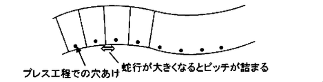
- both side edges of the strip-shaped metal material after slitting will not be parallel straight lines and will have a bend as shown in FIG. Will show the shape.
- Such a bent shape is not suitable for applications that require strict dimensional accuracy. For example, when a lead frame is processed by etching from a strip-shaped metal material, if the bending is large, it is difficult to make holes by a pressing process at a constant interval, and the product yield is significantly reduced.
- Patent Document 1 As a method for preventing the bending, there is known a method of pressing guide rollers arranged in a straight line in the transport direction from both sides of the metal material before the metal material passes through the slitter (eg, Patent Document 1). .
- Patent Document 2 discloses an unwinding and rotating device that sends out a copper strip, a plurality of upper disc cutters and lower disc cutters that shear the copper strip so that it is not completely separated in the thickness direction, It is equipped with a pressing roll that presses the copper strip that has been sheared in the thickness direction to completely separate and cut, and a winding rotary device that winds up the separated and cut copper strip, and the copper strip is elongated.
- the blade tip of the upper disk cutter and the lower disk cutter has a flat portion whose contact angle with the copper strip is 0 °, and a copper strip formed on an extension line of the flat portion,
- a slitting device for a copper strip made of a partially tapered blade tip portion having an inclined portion with an angle of 5 to 30 ° is described, and as a secondary effect of such invention, a slitted thin copper strip is described. The amount of bending of the plate is also reduced.
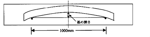
- the amount of bending is usually measured in accordance with JIS H 3100 (2012). Specifically, as shown in FIG. 2, the arc depth with respect to a standard length of 1000 mm at an arbitrary location is set. Say.
- the above means still does not completely solve the problem of reducing the product yield in the pressing process. Furthermore, the present inventors have found that even when the amount of bending measured according to the above JIS standard is lowered, the problem of the defect in the pressing process may not be solved. As a result of further earnest examination by the inventors, when the metal material is continuously cut into a predetermined width along the longitudinal direction to obtain a band-shaped metal material, slight vibrations in the width direction and the vertical direction are generated. It was found that the metal material meanders with a minute cycle.
- Such a meandering with a minute period may not be detected by the JIS standard, and as a result, even if the amount of bending measured by the JIS standard is small, it is suitable for the pressing process. In some cases, a strip-shaped metal material cannot be obtained. Therefore, there is a need for a strip-shaped metal material having a high degree of parallelism that suppresses the bending of the microsnakes and a slit method for obtaining such a strip-shaped metal material. In addition to the above JIS standards, a rational measurement method that reflects the micro-snake bend caused by the minute vibration at the time of slitting is required.
- the strip-shaped metal material has both the amount of bending measured according to JIS standards and the bending that performs micro snakes. For this reason, even if a product whose bending amount measured according to JIS standards is zero can be manufactured, micro-snaked bending does not become zero. This is due to the difference in the cause system between the bending amount measured according to the JIS standard and the bending performed by the micro snake. That is, the occurrence of the bending measured according to the JIS standard is caused by the shape of the material before the slit. The shape of the material before the slit is affected by the finish cold rolling process, the shape correction process after the finish rolling process, or the strain relief annealing process. On the other hand, the generation of the snake-like bend is caused by the slitter equipment and the slit method as described above.
- an object of the present invention is to provide a strip-shaped metal material having high parallelism after slitting and a slit method for obtaining such a strip-shaped metal material, and rationally measure the bending of the strip-shaped material. Is to provide a way to do.
- the present invention includes the following forms. (1) When a straight ruler is applied to the side surface in the longitudinal direction of the band-shaped metal material and a gap in a direction perpendicular to the lengthwise direction of the straight line ruler and the band-shaped metal material is measured every 50 mm in length, 1 m in the longitudinal direction of the band-shaped metal material A band-shaped metal material, wherein the maximum value of the gap is about 0.12 mm or less. (2) The band-shaped metal material according to (1), wherein the amount of bending per 1 m in the longitudinal direction is 0.03 mm or less. (3) The band-shaped metal material according to (1) or (2), wherein the band-shaped metal material is a band-shaped metal material of copper or a copper alloy.
- a slitting process using a slitter having at least a pair of round blade cutters for slitting a metal material into a predetermined band width and a method including the following steps (i) to (iii):
- strip metal Although there is no restriction
- the longitudinal direction of the strip-shaped metal material is 1 m. It is important that the maximum value of the gap is about 0.12 mm or less.
- the present invention applies a straight ruler to the side surface in the longitudinal direction of the strip-shaped metal material, and when the gap in the direction perpendicular to the longitudinal direction of the straight ruler and the strip-shaped metal material is measured every 50 mm in length,
- the maximum value of the gap per 1 m in the longitudinal direction is set to 0.12 mm or less.
- the belt-shaped metal material satisfy the above conditions and have a bending amount per 1 m in the longitudinal direction of 0.03 mm or less.
- the amount of bending is a value obtained by the method of measuring the amount of bending in JIS H 3100 (2012). Thereby, the quality of a strip
- the tensile strength of the band-shaped metal material is 600 MPa or more, it can be said that it has the strength necessary as a material for electric and electronic parts. Since processing may become difficult when tensile strength exceeds 950 MPa, 950 MPa or less is preferable. Similarly, from the viewpoint of achieving both strength and workability, the Vickers hardness of the band-shaped metal material is preferably 180 to 300.
- FIG. 1 The schematic diagram which shows the structure of the slitter equipment (100) based on this embodiment is shown by FIG.
- a long metal material (200) unwound from a payoff reel (not shown) is slit and divided in a slitter (130) to a desired band width while being conveyed in the longitudinal direction.
- the metal material (200) can be wound in a coil shape by a tension reel (not shown).
- the metal material (200) can be loosened in a loop shape before and after the slitter equipment (100). Thereby, adjustment of the conveyance speed of a metal raw material (200) becomes easy.
- the type of metal material (200) to be slit is not particularly limited, and examples include mild steel, copper, copper alloy, and stainless steel. Before the metal material (200) enters the slitter (130), it is desirable to increase the flatness by leveling with a leveler roll or the like in order to obtain the metal material (200) having high parallelism after the slit.
- the thickness of the metal material is preferably 0.10 to 0.16 mm. If the thickness is less than 0.10 mm, the strength is low, and it is difficult to use the metal alone, and bonding with a resin or the like is required. If it exceeds 0.16 mm, it is necessary to set a large bending radius in the bending process, which is not suitable for downsizing of electric and electronic parts.
- the width of the strip-shaped metal material after the slit is preferably set to 100 to 200 mm. If it is less than 100 mm, the productivity is inferior, and if it exceeds 200 mm, it becomes difficult to perform press processing with stable quality in all widths.
- guide roller In front of the slitter (130), guide rollers (120) are installed on both sides of the metal material (200) being conveyed.
- the guide roller (120) is a device for preventing meandering by restricting the plate direction of the metal material (200) from both sides.
- the side surface of the metal material (200) is brought into contact with the side surface of the guide roller (120), thereby preventing meandering and correcting in a predetermined sheet passing direction. Since the rotation axis of the guide roller (120) is parallel to the front and back direction of the metal material (200), the rotation direction of the guide roller when the metal material (200) contacts the guide roller (120) is the metal material ( 200).
- the guide roller (120) In order to ensure the effect of preventing meandering, the guide roller (120) needs to be arranged in a region from a position of a round blade cutter of a slitter described later to a position at least one times the width of the metal material. In order to enhance the meandering prevention effect, a plurality of guide rollers (120) are preferably arranged in a straight line on each side. Moreover, it is preferable that the guide roller (120) is installed in a pair on both opposite sides of the metal material (200).
- the length range in the direction of the plate where the guide roller (120) and the meandering prevention plates (110a, 110b) are installed overlaps at least partially. It is preferable.
- the lower meandering prevention plate (110b) can be placed on an appropriate base or floor, and the upper meandering prevention plate (110a) can be placed on the metal material (200) being conveyed.
- the meandering prevention plates (110a, 110b) need to be arranged in a region from the position of a round blade cutter of a slitter, which will be described later, to a position at least one times the width of the metal material.
- the surface of the meandering prevention plate (110a, 110b) that comes into contact with the metal material (200) is made of friction such as a commercially available non-woven fabric so that the metal material (200) is not scratched and the conveyance resistance is not increased. It is preferable to attach a sheet of a material having low resistance.
- the pressing force against the metal material (200) from the meandering prevention plates (110a, 110b) may be set as appropriate in consideration of the meandering prevention effect. However, even when the meandering weight when the meandering prevention plates (110a, 110b) are veneer plates is sufficient. A sufficient effect can be obtained. When the meandering prevention plate is not sufficiently effective in preventing meandering, a weight can be placed on the meandering prevention plate.
- the width of the meandering prevention plates (110a, 110b) is equal to or larger than the width of the metal material (200), and the meandering prevention effect is enhanced by installing the metal material (200) so that it can be pressed over the entire width of the metal material (200). It is preferable from the viewpoint.
- the length in the plate passing direction of the meandering prevention plates (110a, 110b) may be set as appropriate in consideration of the meandering prevention effect.
- Each of the upper and lower meandering prevention plates (110a, 110b) can be constituted by one piece, or may be constituted by arranging a plurality of pieces in the conveying direction.
- the length of the meandering prevention plates (110a, 110b) in the plate passing direction is preferably 500 to 800 mm.
- the slitter (130) includes two pairs of upper and lower round blade cutters for cutting off margin areas on both sides of a metal material conveyed in the longitudinal direction, and the two pairs of round blade cutters. And at least a pair of upper and lower round blade cutters for cutting the metal material into a predetermined width.
- the meandering prevention plates (140a, 140b, 160a, 160b, 170a, 170b) are arranged in a region from the position of the slitter round blade cutter to a position more than three times the metal material width. There is a need. If the meandering prevention plate (140a, 140b, 160a, 160b, 170a, 170b) is insufficient in its meandering prevention effect, a weight (150) can be further placed on the meandering prevention plate.
- the preferred embodiment of the meandering prevention plates (140a, 140b, 160a, 160b, 170a, 170b) is the same as that of the meandering prevention plates (110a, 110b) in the preceding stage of the slitter (130), and thus the description thereof is omitted.
- the method for measuring the meandering of the strip material of the present invention will be described.
- meandering caused by the slight vibration at the time of the slit can be effectively reflected in the measurement result.
- the pitch is set at a length equal to or less than one-tenth of the length of the belt-shaped material, measured at 10 or more points, and the maximum value of the obtained values is taken as a meandering index value, and the maximum value is below a certain index Things can be passed.
- a measurement table having a plane on which the belt-like material (250) is placed and a plurality of measurement holes (210) provided at a predetermined pitch along the measurement direction on the plane.
- a reference straight ruler (204) is placed on the measurement table (203) along the measurement direction so as to partially close each measurement hole, and the reference straight line in each measurement hole (210) is placed.
- the gap between the ruler (204) and the strip (250) can be measured.
- the spacer (208) can also be arranged along the measurement direction. When such a spacer (208) is arranged, the actual value of the gap between the reference straight ruler (204) and the strip (250) is a value obtained by subtracting the offset of the spacer (208) from the measured value.
- the method for measuring the meandering of the strip material of the present invention can be applied to the strip metal material of the present invention.
- belt-shaped material of this invention can be applied if it is a long strip
- Corson copper alloy (2-4 mass% Ni-0.4-1.0 mass% Si—Cu), which is a metal material having the tensile strength, Vickers hardness, plate thickness and plate width shown in Table 1, is shown in FIG.
- the length (110a, 110b) of the meandering prevention plate before the slitter, the presence / absence of the meandering prevention plate (140a, 140b, 160a, 160b, 170a, 170b) after the slitter, and the strip-like metal material after the slit The width was adjusted as shown in Table 1.
- the operating conditions of the slitter equipment are as follows.
- Guide roller (120) Installed on both sides in a straight line in the direction of the plate. The area where the guide roller is installed is the same as the area where the preceding meandering prevention plates (110a, 110b) are installed.
- Subsequent meandering prevention plates (140a, 140b, 160a, 160b, 170a, 170b) Veneer plates in which a commercially available non-woven fabric is attached to the surface in contact with the metal material. The weight was adjusted so as not to cause scratches.
- Example and Comparative Example Evaluation of each Example and Comparative Example was performed as follows.
- ⁇ Bend> It measured based on JIS H 3100 (2012).
Landscapes
- Engineering & Computer Science (AREA)
- Mechanical Engineering (AREA)
- Physics & Mathematics (AREA)
- General Physics & Mathematics (AREA)
- Shearing Machines (AREA)
- Accessories And Tools For Shearing Machines (AREA)
- Winding, Rewinding, Material Storage Devices (AREA)
- A Measuring Device Byusing Mechanical Method (AREA)
Abstract
スリット後に高い平行度をもつ帯状金属材及びこのような帯状金属材が得られるスリット方法を提供するとともに、帯状材の蛇行を合理的に測定する方法を提供すること。帯状金属材の長手方向の側面に直線定規を当てて直線定規と帯状金属材の長手方向に直角な方向の隙間を長さ50mm毎に測定したとき、当該帯状金属材の長手方向1mあたりの前記隙間の最大値が0.12mm以下であることを特徴とする帯状金属材及びスリット方法並びに帯状材の蛇行測定方法。
Description
本発明は帯状金属材、金属素材を長手方向に沿って所定幅に連続的に切断し帯状金属材を得るためのスリット方法、並びに帯状材の蛇行測定方法に関する。
軟鋼、銅、銅合金、ステンレス等の金属素材の製造ラインでは、金属素材は長手方向に搬送されながら圧延工程で最終板厚とされた後、ユーザーの希望に応じ所定の帯幅にスリットして分割され、それぞれコイル状に巻き取られて出荷される。金属素材を所定の幅にスリットする方法として、金属素材を上下配置された丸刃カッターを備えたスリッターの間を通す方法が慣用的に行なわれている。
スリットされる前の金属素材の形状が平坦でなく波打ったものであると、スリットされた後の帯状金属材の両サイドエッジが平行直線状にならず、図2に示すような曲がりを有した形状を示すことになる。このような曲がりを有した形状では厳しい寸法精度が要求される用途には不向きである。例えば帯状金属材からリードフレームをエッチングにより形状加工する場合、曲がりが大きいと一定間隔でのプレス工程による穴開けが困難となり、製品歩留まりが著しく低下する。
曲がりを防止する方法としては、金属素材がスリッターを通過する前に、金属素材の両サイドから搬送方向に直線上に並んだガイドローラーを押し当てる方法が知られている(例:特許文献1)。
また、特許文献2には、銅帯板を送り出す巻出回転装置と、銅帯板にこれを厚さ方向に完全に分離しない程度にせん断加工を施す複数の上円盤カッタ及び下円盤カッタと、せん断加工が施された銅帯板を厚さ方向に押圧して完全に分離切断する押圧ロールと、分離切断された細銅帯板を巻き取る巻取回転装置とを備え、銅帯板を長手方向に切断するスリッティング装置において、上円盤カッタ及び下円盤カッタの刃先部が、銅帯板との接触角度が0°であるフラット部と、フラット部の延長線上に形成された銅帯板との角度が5~30°である傾斜部とからなる部分テーパー刃先部からなる銅帯板のスリッティング装置が記載されており、かかる発明の副次的な効果として、スリッティングされた細銅帯板の曲がりの量も小さくなる。
ここで、曲がり量の測定は、通常JIS H 3100(2012)に準拠して測定し、具体的には、図2に示すように,任意の箇所の基準の長さ1000mmに対する弧の深さをいう。
しかしながら、上記手段では、依然としてプレス工程における製品歩留まりが低下する課題を完全に解決するに至っていない。さらに、本発明者らは、上記JIS基準により測定される曲がり量を低くしても、プレス工程における不具合の課題が解消されない場合があるということを発見した。
そして、本発明者らがさらに鋭意検討した結果、金属素材を長手方向に沿って所定幅に連続的に切断し帯状金属材を得るに際し、幅方向及び垂直方向の微振動が生じ、これにより帯状金属材が微小な周期で蛇行することを知見した。かかる微小な周期の蛇行(以下「微小蛇行うねり」という。)は、上記JIS基準によっては検出できない場合があり、その結果、上記JIS基準により測定される曲がり量が小さくても、プレス工程に適した帯状金属材を得ることができない場合がある。
そのため、かかる微小蛇行うねりを抑制した平行度の高い帯状金属材、及びこのような帯状金属材が得られるようにするためのスリット方法が必要である。また、上記JIS基準以外、スリットの際の微振動により生じた微小蛇行うねりを反映した合理的な測定方法が必要である。
すなわち、帯状金属材は、JIS基準により測定される曲がり量と、微小蛇行うねりとの両方を有する。そのため、JIS基準により測定される曲がり量がゼロであるものが仮に製造できたとしても、微小蛇行うねりはゼロにはならない。
これは、JIS基準により測定される曲がり量と、微小蛇行うねりとでは、発生の原因系が異なることによるものである。つまり、JIS基準により測定される曲がりの発生は、スリット前における素材の形状に起因する。そして、スリット前における素材の形状は、仕上げ冷間圧延工程、又は、仕上げ圧延工程後の形状矯正工程若しくは歪取焼鈍工程に影響を受ける。一方、微小蛇行うねりの発生は上記のとおりスリッタ設備及びスリット方法に起因する。
そして、本発明者らがさらに鋭意検討した結果、金属素材を長手方向に沿って所定幅に連続的に切断し帯状金属材を得るに際し、幅方向及び垂直方向の微振動が生じ、これにより帯状金属材が微小な周期で蛇行することを知見した。かかる微小な周期の蛇行(以下「微小蛇行うねり」という。)は、上記JIS基準によっては検出できない場合があり、その結果、上記JIS基準により測定される曲がり量が小さくても、プレス工程に適した帯状金属材を得ることができない場合がある。
そのため、かかる微小蛇行うねりを抑制した平行度の高い帯状金属材、及びこのような帯状金属材が得られるようにするためのスリット方法が必要である。また、上記JIS基準以外、スリットの際の微振動により生じた微小蛇行うねりを反映した合理的な測定方法が必要である。
すなわち、帯状金属材は、JIS基準により測定される曲がり量と、微小蛇行うねりとの両方を有する。そのため、JIS基準により測定される曲がり量がゼロであるものが仮に製造できたとしても、微小蛇行うねりはゼロにはならない。
これは、JIS基準により測定される曲がり量と、微小蛇行うねりとでは、発生の原因系が異なることによるものである。つまり、JIS基準により測定される曲がりの発生は、スリット前における素材の形状に起因する。そして、スリット前における素材の形状は、仕上げ冷間圧延工程、又は、仕上げ圧延工程後の形状矯正工程若しくは歪取焼鈍工程に影響を受ける。一方、微小蛇行うねりの発生は上記のとおりスリッタ設備及びスリット方法に起因する。
そこで、本発明の課題は、スリット後に高い平行度をもつ帯状金属材及びこのような帯状金属材が得られるようにするためスリット方法を提供するとともに、帯状材の微小蛇行うねりを合理的に測定する方法を提供することである。
本発明は、以下のような形態を含むものである。
(1)帯状金属材の長手方向の側面に直線定規を当てて直線定規と帯状金属材の長手方向に直角な方向の隙間を長さ50mm毎に測定したとき、当該帯状金属材の長手方向1mあたりの前記隙間の最大値が0.12mm以下であることを特徴とする帯状金属材。
(2)長手方向1mあたりの曲がり量が0.03mm以下であることを特徴とする(1)に記載の帯状金属材。
(3)前記帯状金属材が銅又は銅合金の帯状金属材であることを特徴とする(1)又は(2)に記載の帯状金属材。
(4)金属素材を長手方向に搬送しながら所定の帯幅にスリットする方法であって、
長手方向に搬送される金属素材の両サイドのマージン領域を切り落とすための二対の丸刃カッターと、前記二対の丸刃カッターの各内側に配置され、前記金属素材を所定の幅に切断するための少なくとも一対の丸刃カッターを有するスリッターを用いて、金属素材を所定の帯幅にスリットするスリット工程と、以下の(i)~(iii)の工程を実施することを含む方法。
(i)前記スリット工程の前、長手方向に搬送される金属素材の動きを、丸刃カッターの位置から、金属素材幅の少なくとも1倍の位置までの領域において、金属素材の通板方向を両サイドから規制する工程。
(ii)前記スリット工程の前、長手方向に搬送される金属素材の動きを、丸刃カッターの位置から、金属素材幅の少なくとも1倍の位置までの領域において、表裏方向から規制する工程。
(iii)前記スリット工程の後、前記スリットされた金属素材の動きを、丸刃カッターの位置から、金属素材幅の3倍の位置までの領域において、少なくとも1か所以上の位置で表裏方向から規制する工程。
(5)長手方向に搬送される金属素材の動きを両サイド及び表裏方向から規制する工程を実施する前に、金属素材をレベラー矯正する工程を更に含む(4)に記載の方法。
(6)帯状材の蛇行測定方法であって、長手方向一定長さに切り取った帯状材側面に直線定規を当てて直線定規と帯状材の長手方向に直角な方向の隙間を一定長さのピッチ毎に測定することを特徴とする蛇行測定方法。
(7)前記ピッチが帯状材長さの10分の1以下であることを特徴とする(6)に記載の蛇行測定方法。
(1)帯状金属材の長手方向の側面に直線定規を当てて直線定規と帯状金属材の長手方向に直角な方向の隙間を長さ50mm毎に測定したとき、当該帯状金属材の長手方向1mあたりの前記隙間の最大値が0.12mm以下であることを特徴とする帯状金属材。
(2)長手方向1mあたりの曲がり量が0.03mm以下であることを特徴とする(1)に記載の帯状金属材。
(3)前記帯状金属材が銅又は銅合金の帯状金属材であることを特徴とする(1)又は(2)に記載の帯状金属材。
(4)金属素材を長手方向に搬送しながら所定の帯幅にスリットする方法であって、
長手方向に搬送される金属素材の両サイドのマージン領域を切り落とすための二対の丸刃カッターと、前記二対の丸刃カッターの各内側に配置され、前記金属素材を所定の幅に切断するための少なくとも一対の丸刃カッターを有するスリッターを用いて、金属素材を所定の帯幅にスリットするスリット工程と、以下の(i)~(iii)の工程を実施することを含む方法。
(i)前記スリット工程の前、長手方向に搬送される金属素材の動きを、丸刃カッターの位置から、金属素材幅の少なくとも1倍の位置までの領域において、金属素材の通板方向を両サイドから規制する工程。
(ii)前記スリット工程の前、長手方向に搬送される金属素材の動きを、丸刃カッターの位置から、金属素材幅の少なくとも1倍の位置までの領域において、表裏方向から規制する工程。
(iii)前記スリット工程の後、前記スリットされた金属素材の動きを、丸刃カッターの位置から、金属素材幅の3倍の位置までの領域において、少なくとも1か所以上の位置で表裏方向から規制する工程。
(5)長手方向に搬送される金属素材の動きを両サイド及び表裏方向から規制する工程を実施する前に、金属素材をレベラー矯正する工程を更に含む(4)に記載の方法。
(6)帯状材の蛇行測定方法であって、長手方向一定長さに切り取った帯状材側面に直線定規を当てて直線定規と帯状材の長手方向に直角な方向の隙間を一定長さのピッチ毎に測定することを特徴とする蛇行測定方法。
(7)前記ピッチが帯状材長さの10分の1以下であることを特徴とする(6)に記載の蛇行測定方法。
本発明によれば、蛇行を抑制した平行度の高い帯状金属材を得ることができ、上記プレス工程における不具合を有効に抑制することができる。
(帯状金属材)
帯状金属材の種類としては特に制限はないが、例えば軟鋼、銅、銅合金、ステンレス等が挙げられる。
ここで、帯状金属材の長手方向の側面に直線定規を当てて直線定規と帯状金属材の長手方向に直角な方向の隙間を長さ50mm毎に測定したとき、当該帯状金属材の長手方向1mあたりの前記隙間の最大値が0.12mm以下であることが肝要である。
前述のように、金属素材を長手方向に沿って所定幅に連続的に切断し帯状金属材を得るに際し、幅方向及び垂直方向の微振動が生じ、これにより帯状金属材が蛇行する。このような微振動から生じる蛇行は、必ずしも帯状金属材の曲がりとして現れるとは限らないため、JIS H 3100(2012)における曲がり量の測定方法では正確に測定できない場合がある。このような蛇行を正確に評価するには、JIS H 3100(2012)における方法よりも、測定点を増やす必要がある。そのため、本発明は、帯状金属材の長手方向の側面に直線定規を当てて直線定規と帯状金属材の長手方向に直角な方向の隙間を長さ50mm毎に測定したとき、当該帯状金属材の長手方向1mあたりの前記隙間の最大値が0.12mm以下であると設定している。これにより多数の測定点から隙間の値を得ることができ、微振動から生じる蛇行を正確に反映させることができる。その結果、その後のプレス工程等に適した帯状金属材を確実に提供することができる。
前記隙間の最大値を測定する方法の詳細は後述する。
帯状金属材の種類としては特に制限はないが、例えば軟鋼、銅、銅合金、ステンレス等が挙げられる。
ここで、帯状金属材の長手方向の側面に直線定規を当てて直線定規と帯状金属材の長手方向に直角な方向の隙間を長さ50mm毎に測定したとき、当該帯状金属材の長手方向1mあたりの前記隙間の最大値が0.12mm以下であることが肝要である。
前述のように、金属素材を長手方向に沿って所定幅に連続的に切断し帯状金属材を得るに際し、幅方向及び垂直方向の微振動が生じ、これにより帯状金属材が蛇行する。このような微振動から生じる蛇行は、必ずしも帯状金属材の曲がりとして現れるとは限らないため、JIS H 3100(2012)における曲がり量の測定方法では正確に測定できない場合がある。このような蛇行を正確に評価するには、JIS H 3100(2012)における方法よりも、測定点を増やす必要がある。そのため、本発明は、帯状金属材の長手方向の側面に直線定規を当てて直線定規と帯状金属材の長手方向に直角な方向の隙間を長さ50mm毎に測定したとき、当該帯状金属材の長手方向1mあたりの前記隙間の最大値が0.12mm以下であると設定している。これにより多数の測定点から隙間の値を得ることができ、微振動から生じる蛇行を正確に反映させることができる。その結果、その後のプレス工程等に適した帯状金属材を確実に提供することができる。
前記隙間の最大値を測定する方法の詳細は後述する。
また、上記条件を満たすとともに、長手方向1mあたりの曲がり量が0.03mm以下である帯状金属材であることが好ましい。かかる曲がり量は、JIS H 3100(2012)における曲がり量の測定方法により得られた値である。これにより、帯状金属材の品質をさらに確実に担保することができる。
帯状金属材の引張強さが600MPa以上であれば、電気電子部品の素材として必要な強度を有しているといえる。引張強さが950MPaを超えると加工が困難となる場合もあるので、950MPa以下が好ましい。また、同じく強度と加工性を両立させる観点から、帯状金属材のビッカース硬さは180~300とすることが好ましい。
次に、図面を参照しながら本発明のスリッター設備及びスリット方法説明する。図3には本実施形態に係るスリッター設備(100)の構成を示す模式図が示されている。ペイオフリール(図示せず)から巻き出された長尺の金属素材(200)が長手方向に搬送されながらスリッター(130)において所望の帯幅にスリットして分割される。分割後、金属素材(200)はそれぞれテンションリール(図示せず)でコイル状に巻き取ることができる。図示しないが、金属素材(200)はスリッター設備(100)の前段及び後段ではループ状に弛ませることができる。これにより、金属素材(200)の搬送速度の調整が容易となる。
スリットする金属素材(200)の種類としては特に制限はないが、例えば軟鋼、銅、銅合金、ステンレス等が挙げられる。金属素材(200)がスリッター(130)に入る前に、レベラーロールなどでレベラー矯正して平坦度を高めておくことが、スリット後に高い平行度をもつ金属素材(200)を得る上では望ましい。金属素材の厚みは0.10~0.16mmとすることが好ましい。0.10mm未満のものは強度が低く、金属単体での使用が難しく樹脂等との貼り合わせが必要となる。0.16mmを超えると曲げ加工において曲げ半径を大きく設定する必要があり、電気電子部品の小型化に不向きである。また、スリット後の帯状金属材の幅は100~200mmと設定することが好ましい。100mm未満のものは生産性が劣り、200mmを超えるものは全ての幅において品質が安定したプレス加工をすることが難しくなる。
(ガイドローラー)
スリッター(130)の前段には、搬送中の金属素材(200)の両サイドにガイドローラー(120)が設置されている。ガイドローラー(120)は金属素材(200)の通板方向を両サイドから規制することで蛇行を防止するための装置である。搬送中の金属素材(200)が蛇行しかけると、金属素材(200)の側面がガイドローラー(120)の側面に当接することで、蛇行を阻止して所定の通板方向に矯正する。ガイドローラー(120)の回転軸が金属素材(200)の表裏方向と平行であることで、金属素材(200)がガイドローラー(120)に当接したときのガイドローラーの回転方向が金属素材(200)の通板方向と一致する。これにより金属素材(200)とガイドローラー(120)の間の摩擦を低減することが可能となる。蛇行防止効果を確保するため、ガイドローラー(120)は後述するスリッターの丸刃カッターの位置から、金属素材幅の少なくとも1倍の位置までの領域内に配置する必要がある。蛇行防止効果を高めるため、ガイドローラー(120)は各サイドに直線状に複数配列することが好ましい。また、ガイドローラー(120)は金属素材(200)の対向する両サイドにペアで設置されていることが好ましい。
スリッター(130)の前段には、搬送中の金属素材(200)の両サイドにガイドローラー(120)が設置されている。ガイドローラー(120)は金属素材(200)の通板方向を両サイドから規制することで蛇行を防止するための装置である。搬送中の金属素材(200)が蛇行しかけると、金属素材(200)の側面がガイドローラー(120)の側面に当接することで、蛇行を阻止して所定の通板方向に矯正する。ガイドローラー(120)の回転軸が金属素材(200)の表裏方向と平行であることで、金属素材(200)がガイドローラー(120)に当接したときのガイドローラーの回転方向が金属素材(200)の通板方向と一致する。これにより金属素材(200)とガイドローラー(120)の間の摩擦を低減することが可能となる。蛇行防止効果を確保するため、ガイドローラー(120)は後述するスリッターの丸刃カッターの位置から、金属素材幅の少なくとも1倍の位置までの領域内に配置する必要がある。蛇行防止効果を高めるため、ガイドローラー(120)は各サイドに直線状に複数配列することが好ましい。また、ガイドローラー(120)は金属素材(200)の対向する両サイドにペアで設置されていることが好ましい。
(スリッター前段の蛇行防止板)
ただし、ガイドローラー(120)の設置のみでは蛇行防止効果は限定的であり、蛇行を高い次元で阻止することはできない。また、ガイドローラー(120)のみでは金属素材(200)は上下方向への動きが規制されていないため、波打が発生したり、金属素材(200)がガイドローラー(120)へ乗り上げたりする場合もある。そこで、スリッター(130)の前段には、更なる蛇行防止手段として、金属素材(200)を上下から押さえるための一対の蛇行防止板(110a、110b)を設置することが効果的である。蛇行防止、波打防止、ガイドローラー(120)への乗り上げ防止の観点から、ガイドローラー(120)と蛇行防止板(110a、110b)を設置する通板方向の長さ範囲は少なくとも部分的に重複していることが好ましい。下側の蛇行防止板(110b)を適切な土台や床上に敷き、その上に、搬送中の金属素材(200)を挟むようにして上側の蛇行防止板(110a)を載置することができる。ガイドローラー(120)に加えて蛇行防止板(110a、110b)を設置することで、金属素材(200)の蛇行、波打及びガイドローラーへの乗り上げが抑制されるので、より平坦な状態で元材をスリット工程に進入させることが可能となる。蛇行防止効果を確保するため、蛇行防止板(110a、110b)は後述するスリッターの丸刃カッターの位置から、金属素材幅の少なくとも1倍の位置までの領域内に配置する必要がある。
ただし、ガイドローラー(120)の設置のみでは蛇行防止効果は限定的であり、蛇行を高い次元で阻止することはできない。また、ガイドローラー(120)のみでは金属素材(200)は上下方向への動きが規制されていないため、波打が発生したり、金属素材(200)がガイドローラー(120)へ乗り上げたりする場合もある。そこで、スリッター(130)の前段には、更なる蛇行防止手段として、金属素材(200)を上下から押さえるための一対の蛇行防止板(110a、110b)を設置することが効果的である。蛇行防止、波打防止、ガイドローラー(120)への乗り上げ防止の観点から、ガイドローラー(120)と蛇行防止板(110a、110b)を設置する通板方向の長さ範囲は少なくとも部分的に重複していることが好ましい。下側の蛇行防止板(110b)を適切な土台や床上に敷き、その上に、搬送中の金属素材(200)を挟むようにして上側の蛇行防止板(110a)を載置することができる。ガイドローラー(120)に加えて蛇行防止板(110a、110b)を設置することで、金属素材(200)の蛇行、波打及びガイドローラーへの乗り上げが抑制されるので、より平坦な状態で元材をスリット工程に進入させることが可能となる。蛇行防止効果を確保するため、蛇行防止板(110a、110b)は後述するスリッターの丸刃カッターの位置から、金属素材幅の少なくとも1倍の位置までの領域内に配置する必要がある。
蛇行防止板(110a、110b)の金属素材(200)と接触する面には、金属素材(200)にキズが付かないように、また、搬送抵抗が大きくならないように、市販の不織布などの摩擦抵抗の低い材質のシートを貼り付けることが好ましい。蛇行防止板(110a、110b)からの金属素材(200)に対する押圧力は蛇行防止効果との兼ね合いで適宜設定すればよいが、蛇行防止板(110a、110b)をベニヤ板としたときの自重程度でも十分な効果が得られる。蛇行防止板の自重では蛇行防止効果が不十分な場合は蛇行防止板の上に更に重りを載せることもできる。
蛇行防止板(110a、110b)の幅は金属素材(200)の幅以上とし、金属素材(200)の幅方向全体にわたって金属素材(200)を押圧できるように設置することが蛇行防止効果を高める観点で好ましい。蛇行防止板(110a、110b)の通板方向の長さは蛇行防止効果との兼ね合いで適宜設定すればよい。上下の蛇行防止板(110a、110b)はそれぞれ一枚で構成することもでき、搬送方向に複数枚配列することで構成してもよい。具体的には、蛇行防止板(110a、110b)の通板方向の長さは500~800mmとすることが好ましい。
(スリッター)
図3を参照すると、スリッター(130)は一実施形態において、長手方向に搬送される金属素材の両サイドのマージン領域を切り落とすための上下二対の丸刃カッターと、前記二対の丸刃カッターの各内側に配置され、前記金属素材を所定の幅に切断するための少なくとも上下一対の丸刃カッターを有することができる。
図3を参照すると、スリッター(130)は一実施形態において、長手方向に搬送される金属素材の両サイドのマージン領域を切り落とすための上下二対の丸刃カッターと、前記二対の丸刃カッターの各内側に配置され、前記金属素材を所定の幅に切断するための少なくとも上下一対の丸刃カッターを有することができる。
(スリッター後段の蛇行防止板)
スリット後の金属素材(200)の平行度を顕著に高めるためには、スリッター(130)の後段にも蛇行防止板(140a、140b、160a、160b、170a、170b)を設置することが効果的となる。スリット後の金属素材(200)の蛇行を防止することでスリット後の金属素材(200)が重なることを防止でき、また、スリット後の金属素材(200)の蛇行を防止することはスリット前及びスリット中の金属素材(200)の蛇行防止にも寄与する。蛇行防止効果を確保するため、蛇行防止板(140a、140b、160a、160b、170a、170b)はスリッターの丸刃カッターの位置から、金属素材幅の3倍以上の位置までの領域内に配置する必要がある。蛇行防止板(140a、140b、160a、160b、170a、170b)の自重では蛇行防止効果が不十分な場合は蛇行防止板の上に更に重り(150)を載せることもできる。蛇行防止板(140a、140b、160a、160b、170a、170b)の好適な態様はスリッター(130)前段の蛇行防止板(110a、110b)と同様であるので、説明を省略する。
スリット後の金属素材(200)の平行度を顕著に高めるためには、スリッター(130)の後段にも蛇行防止板(140a、140b、160a、160b、170a、170b)を設置することが効果的となる。スリット後の金属素材(200)の蛇行を防止することでスリット後の金属素材(200)が重なることを防止でき、また、スリット後の金属素材(200)の蛇行を防止することはスリット前及びスリット中の金属素材(200)の蛇行防止にも寄与する。蛇行防止効果を確保するため、蛇行防止板(140a、140b、160a、160b、170a、170b)はスリッターの丸刃カッターの位置から、金属素材幅の3倍以上の位置までの領域内に配置する必要がある。蛇行防止板(140a、140b、160a、160b、170a、170b)の自重では蛇行防止効果が不十分な場合は蛇行防止板の上に更に重り(150)を載せることもできる。蛇行防止板(140a、140b、160a、160b、170a、170b)の好適な態様はスリッター(130)前段の蛇行防止板(110a、110b)と同様であるので、説明を省略する。
次に、本発明の帯状材の蛇行測定方法について説明する。帯状材の蛇行を測定するにあたり、長手方向一定長さに切り取った帯状材側面に直線定規を当てて、当該直線定規と当該帯状材の長手方向に直角な方向の隙間を一定長さのピッチ毎に測定する。これにより、スリットの際の微振動により生じた蛇行を測定結果に有効に反映させることができる。例えば、帯状材長さの10分の1以下の長さでピッチを設定し、10点以上測定し、得られた値の最大値を蛇行の指標値として、当該最大値が一定の指標以下のものを合格とすることができる。
例えば、図4に示すように、帯状材(250)を載置するための平面、及び該平面上に測定方向に沿って所定のピッチで設けられた複数の測定穴(210)を有する測定テーブル(203)上に、各測定穴を部分的に塞ぐようにして測定方向に沿って前記測定テーブル(203)上に基準直定規(204)を載置し、各測定穴(210)における基準直定規(204)と帯状材(250)の隙間を測定することができる。ここで、基準直定規(204)と帯状材(250)の隙間の測定の容易にするため、帯状材(250)を基準直定規(204)から各測定穴を部分的に塞ぐことのできる距離で測定方向に沿ってスペーサ(208)を配置することもできる。かかるスペーサ(208)を配置する場合、基準直定規(204)と帯状材(250)の隙間の実際値は、測定値からスペーサ(208)のオフセットを減じて得た値である。
本発明の帯状材の蛇行測定方法は、本発明の帯状金属材に適用することができる。また、本発明の帯状材の蛇行測定方法は、長尺状の帯状材であれば適用することができ、必ずしも帯状金属材に適用しなくてもよい。
以下に本発明の実施例を示すが、実施例は本発明及びその利点をよりよく理解するために提供するものであり、発明が限定されることを意図するものではない。
表1に示す引張強さ、ビッカース硬さ、板厚及び板幅を有する金属素材であるコルソン銅合金(2~4質量%Ni-0.4~1.0質量%Si-Cu)を図3に示す構造を有するスリッター設備を用いて、金属素材に対してスリット加工を行った。各実施例及び発明例について、スリッター前段の蛇行防止板の長さ(110a、110b)、スリッター後段の蛇行防止板(140a、140b、160a、160b、170a、170b)の有無、スリット後帯状金属材の幅も表1に示すとおり調節した。
スリッター設備の操業条件は以下である。
ガイドローラー(120):通板方向に直線状に両サイドに設置。ガイドローラーを設置する領域は、前段の蛇行防止板(110a、110b)を設置する領域と同じものとした。
前段の蛇行防止板(110a、110b):金属素材と接する面に市販の不織布を貼り付けたベニヤ板。スリキズ発生しないように重さを調整した。
後段の蛇行防止板(140a、140b、160a、160b、170a、170b):金属素材と接する面に市販の製の不織布を貼り付けたベニヤ板。スリキズ発生しないように重さを調整した。
重り(150):スリキズ発生しないように重さを調整した。
ガイドローラー(120):通板方向に直線状に両サイドに設置。ガイドローラーを設置する領域は、前段の蛇行防止板(110a、110b)を設置する領域と同じものとした。
前段の蛇行防止板(110a、110b):金属素材と接する面に市販の不織布を貼り付けたベニヤ板。スリキズ発生しないように重さを調整した。
後段の蛇行防止板(140a、140b、160a、160b、170a、170b):金属素材と接する面に市販の製の不織布を貼り付けたベニヤ板。スリキズ発生しないように重さを調整した。
重り(150):スリキズ発生しないように重さを調整した。
それぞれの実施例及び比較例の評価は以下のように行った。
<引張強さ>
引張試験機により、JIS-Z2241に従い、圧延方向と平行な方向における引張強さを測定した。
<ビッカース硬さ>
JIS-Z-2244(2009)に従い、マイクロビッカース硬さ試験を、荷重:0.098Nで行い、マイクロビッカース硬さを測定した。
<曲がり>
JIS H 3100(2012)に準拠して測定した。
<微小蛇行うねり>
スリット後の帯状金属材の長手方向に沿って1m分切り抜き、その長手方向の側面に直線定規を当てて直線定規と帯状金属材の長手方向に直角な方向の隙間を長さ50mm毎に測定し、その最大値を微小蛇行うねりの値とした。
<プレスの不具合の有無>
図2に示すように、送りピッチ(送り長さ)でパイロット穴を作製する工程、送りピッチ(送り長さ)で材料を送る工程、送りピッチ(送り長さ)でパイロット穴にパイロットパンチを挿入させる工程を順次行い、この一連の動作を繰り返すことにより帯状金属帯を連続して送るプレス試験を行った。プレス試験において次のように、不具合あり及び不具合なしを判定した。
・プレス不具合あり:帯状金属帯の送りが停止した。
・プレス不具合あり:プレス後の帯状金属帯のエッジが、プレス機構造部との接触により変形した。
・プレス不具合あり:プレス後の帯状金属帯のエッジにプレス機構造部との接触によるキズが発生した。
・プレス不具合なし:上記の停止、変形及びキズのいずれも認められなかった。
<引張強さ>
引張試験機により、JIS-Z2241に従い、圧延方向と平行な方向における引張強さを測定した。
<ビッカース硬さ>
JIS-Z-2244(2009)に従い、マイクロビッカース硬さ試験を、荷重:0.098Nで行い、マイクロビッカース硬さを測定した。
<曲がり>
JIS H 3100(2012)に準拠して測定した。
<微小蛇行うねり>
スリット後の帯状金属材の長手方向に沿って1m分切り抜き、その長手方向の側面に直線定規を当てて直線定規と帯状金属材の長手方向に直角な方向の隙間を長さ50mm毎に測定し、その最大値を微小蛇行うねりの値とした。
<プレスの不具合の有無>
図2に示すように、送りピッチ(送り長さ)でパイロット穴を作製する工程、送りピッチ(送り長さ)で材料を送る工程、送りピッチ(送り長さ)でパイロット穴にパイロットパンチを挿入させる工程を順次行い、この一連の動作を繰り返すことにより帯状金属帯を連続して送るプレス試験を行った。プレス試験において次のように、不具合あり及び不具合なしを判定した。
・プレス不具合あり:帯状金属帯の送りが停止した。
・プレス不具合あり:プレス後の帯状金属帯のエッジが、プレス機構造部との接触により変形した。
・プレス不具合あり:プレス後の帯状金属帯のエッジにプレス機構造部との接触によるキズが発生した。
・プレス不具合なし:上記の停止、変形及びキズのいずれも認められなかった。

実施例1~11は、蛇行の値が0.12mm以下であるため、その後のプレス工程で不具合はなかった。曲がりの値も0.03mm以下に抑えることができた。
一方、比較例1~6は、蛇行の値が0.13mmを超えたため、その後のプレス工程で不具合が生じた。特に、比較例1~3において、曲がりの値は低い水準にあるが、蛇行の値が高かったため、プレス工程での不具合を抑えることができなかったことがわかる。
一方、比較例1~6は、蛇行の値が0.13mmを超えたため、その後のプレス工程で不具合が生じた。特に、比較例1~3において、曲がりの値は低い水準にあるが、蛇行の値が高かったため、プレス工程での不具合を抑えることができなかったことがわかる。
110a、110b 前段の蛇行防止板
120 蛇行防止用ガイドローラー
130 スリッター
140a、140b、160a、160b、170a、170b 後段の蛇行防止板
150 重り
200 金属素材
203 測定テーブル
204 基準直定規
208 スペーサ
210 測定穴
250 帯状材
120 蛇行防止用ガイドローラー
130 スリッター
140a、140b、160a、160b、170a、170b 後段の蛇行防止板
150 重り
200 金属素材
203 測定テーブル
204 基準直定規
208 スペーサ
210 測定穴
250 帯状材
Claims (7)
- 帯状金属材の長手方向の側面に直線定規を当てて直線定規と帯状金属材の長手方向に直角な方向の隙間を長さ50mm毎に測定したとき、当該帯状金属材の長手方向1mあたりの前記隙間の最大値が0.12mm以下であることを特徴とする帯状金属材。
- 長手方向1mあたりの曲がり量が0.03mm以下であることを特徴とする請求項1に記載の帯状金属材。
- 前記帯状金属材が銅又は銅合金の帯状金属材であることを特徴とする請求項1又は2に記載の帯状金属材。
- 金属素材を長手方向に搬送しながら所定の帯幅にスリットする方法であって、
長手方向に搬送される金属素材の両サイドのマージン領域を切り落とすための二対の丸刃カッターと、前記二対の丸刃カッターの各内側に配置され、前記金属素材を所定の幅に切断するための少なくとも一対の丸刃カッターを有するスリッターを用いて、金属素材を所定の帯幅にスリットするスリット工程と、以下の(1)~(3)の工程を実施することを含む方法。
(1)前記スリット工程の前、長手方向に搬送される金属素材の動きを、丸刃カッターの位置から、金属素材幅の少なくとも1倍の位置までの領域において、金属素材の通板方向を両サイドから規制する工程。
(2)前記スリット工程の前、長手方向に搬送される金属素材の動きを、丸刃カッターの位置から、金属素材幅の少なくとも1倍の位置までの領域において、表裏方向から規制する工程。
(3)前記スリット工程の後、前記スリットされた金属素材の動きを、丸刃カッターの位置から、金属素材幅の3倍の位置までの領域において、少なくとも1か所以上の位置で表裏方向から規制する工程。 - 長手方向に搬送される金属素材の動きを両サイド及び表裏方向から規制する工程を実施する前に、金属素材をレベラー矯正する工程を更に含む請求項4に記載の方法。
- 帯状材の蛇行測定方法であって、長手方向一定長さに切り取った帯状材側面に直線定規を当てて直線定規と帯状材の長手方向に直角な方向の隙間を一定長さのピッチ毎に測定することを特徴とする蛇行測定方法。
- 前記ピッチが帯状材長さの10分の1以下であることを特徴とする請求項6に記載の蛇行測定方法。
Priority Applications (4)
| Application Number | Priority Date | Filing Date | Title |
|---|---|---|---|
| CN201880022325.6A CN110475639A (zh) | 2017-03-31 | 2018-03-09 | 带状金属材、纵切方法及带状材的蛇行测量方法 |
| KR1020197031826A KR20190133735A (ko) | 2017-03-31 | 2018-03-09 | 띠상 금속재, 슬릿 방법 및 띠상재의 사행 측정 방법 |
| MYPI2019005684A MY203137A (en) | 2017-03-31 | 2018-03-09 | Metal strip material, slitting method, and measuring method for strip material meandering |
| KR1020217020443A KR102425952B1 (ko) | 2017-03-31 | 2018-03-09 | 띠상 금속재, 슬릿 방법 및 띠상재의 사행 측정 방법 |
Applications Claiming Priority (2)
| Application Number | Priority Date | Filing Date | Title |
|---|---|---|---|
| JP2017070411A JP6787832B2 (ja) | 2017-03-31 | 2017-03-31 | 帯状金属材の製造方法 |
| JP2017-070411 | 2017-03-31 |
Publications (1)
| Publication Number | Publication Date |
|---|---|
| WO2018180378A1 true WO2018180378A1 (ja) | 2018-10-04 |
Family
ID=63677413
Family Applications (1)
| Application Number | Title | Priority Date | Filing Date |
|---|---|---|---|
| PCT/JP2018/009295 Ceased WO2018180378A1 (ja) | 2017-03-31 | 2018-03-09 | 帯状金属材、スリット方法並びに帯状材の蛇行測定方法 |
Country Status (6)
| Country | Link |
|---|---|
| JP (1) | JP6787832B2 (ja) |
| KR (2) | KR102425952B1 (ja) |
| CN (2) | CN110475639A (ja) |
| MY (1) | MY203137A (ja) |
| TW (1) | TWI663009B (ja) |
| WO (1) | WO2018180378A1 (ja) |
Citations (9)
| Publication number | Priority date | Publication date | Assignee | Title |
|---|---|---|---|---|
| JPS5932315U (ja) * | 1982-08-21 | 1984-02-28 | 新日本製鐵株式会社 | サイドトリミング装置 |
| JPS6099515A (ja) * | 1983-11-01 | 1985-06-03 | Sumitomo Heavy Ind Ltd | シヤラインにおけるシヤカツトマ−ク防止装置 |
| JPH08206915A (ja) * | 1995-02-01 | 1996-08-13 | Nkk Corp | 鋼板剪断ラインの搬送装置 |
| JPH09225726A (ja) * | 1996-02-22 | 1997-09-02 | Ono Roll Kk | スリッターマシン |
| JPH09253921A (ja) * | 1996-03-22 | 1997-09-30 | Nisshin Steel Co Ltd | 製品の保護と耐用性に優れたサイドトリーマ |
| JPH1194505A (ja) * | 1997-09-17 | 1999-04-09 | Nkk Corp | 鋼板の横曲がり測定方法及び装置 |
| JP2001137955A (ja) * | 1999-11-08 | 2001-05-22 | Mitsubishi Heavy Ind Ltd | メンブレンの製造装置及びその製造方法 |
| JP2002022401A (ja) * | 2000-07-05 | 2002-01-23 | Misawa Ceramics Corp | 長尺部の反り曲がり寸法測定器 |
| JP2013244577A (ja) * | 2012-05-28 | 2013-12-09 | Mitsubishi Shindoh Co Ltd | 銅帯板のスリッティング装置及びスリッティング方法 |
Family Cites Families (30)
| Publication number | Priority date | Publication date | Assignee | Title |
|---|---|---|---|---|
| US4187710A (en) * | 1978-06-12 | 1980-02-12 | Industrial Blast Coil Corporation | Method and apparatus for simultaneously rolling and slitting metal strip |
| JPH0739048B2 (ja) * | 1986-12-04 | 1995-05-01 | 川崎製鉄株式会社 | 金属ストリツプの側端部品質及びストリツプ蛇行修正機能の診断方法 |
| JPH05237718A (ja) * | 1992-02-28 | 1993-09-17 | Mitsubishi Heavy Ind Ltd | 厚板スリッタの板材蛇行防止装置 |
| JPH06126407A (ja) * | 1992-10-22 | 1994-05-10 | Sumitomo Heavy Ind Ltd | 連続鋳造機等における鋳片の端面位置検出及び切断確認方法 |
| JP3091073B2 (ja) * | 1994-03-18 | 2000-09-25 | 住友金属工業株式会社 | ストリップの蛇行修正用ピンチロール、蛇行修正装置および蛇行修正方法 |
| TW336184B (en) * | 1995-01-11 | 1998-07-11 | Tippins Inc | Intermediate thickness slab caster and inline hot strip and plate line, method of processing metal slabs and slab container |
| JPH10109217A (ja) | 1996-10-02 | 1998-04-28 | Mitsui High Tec Inc | スリッターのサイドガイド装置 |
| KR19990005560U (ko) * | 1997-07-18 | 1999-02-18 | 김종진 | 압연판 표면의 평탄도 측정장치 |
| JPH11333619A (ja) * | 1998-05-28 | 1999-12-07 | Kawasaki Steel Corp | トリミング装置 |
| JP2000225512A (ja) * | 1999-02-09 | 2000-08-15 | Nippon Steel Corp | サイドトリマー装置 |
| JP2002243648A (ja) | 2001-02-20 | 2002-08-28 | Sumitomo Metal Mining Co Ltd | 帯状金属処理面の検査装置 |
| ITMI20021996A1 (it) * | 2002-09-19 | 2004-03-20 | Giovanni Arvedi | Procedimento e linea di produzione per la fabbricazione di nastro a caldo ultrasottile sulla base della tecnologia della bramma sottile |
| JP2008055555A (ja) | 2006-08-31 | 2008-03-13 | Jfe Steel Kk | サイドトリミング装置 |
| KR100983095B1 (ko) | 2008-05-19 | 2010-09-17 | 주식회사 케이시스템 | 이송중인 금속판 제원 측정시스템 및 측정방법 |
| KR101420476B1 (ko) * | 2008-09-02 | 2014-07-16 | 도요타지도샤가부시키가이샤 | 전극 시트의 제조 방법 및 그 장치 |
| CN101670372B (zh) * | 2009-09-25 | 2011-01-26 | 首钢总公司 | 一种消除热轧高强钢板形缺陷的方法 |
| WO2011065331A1 (ja) * | 2009-11-24 | 2011-06-03 | 住友電気工業株式会社 | マグネシウム合金コイル材 |
| WO2011114441A1 (ja) * | 2010-03-16 | 2011-09-22 | 株式会社ニレコ | ウェブ中心位置制御装置、方法及びプログラム並びにウェブトリミング装置 |
| KR101175795B1 (ko) * | 2010-03-30 | 2012-08-21 | 현대제철 주식회사 | 소재 위치 측정장치 |
| IT1400629B1 (it) * | 2010-06-22 | 2013-06-14 | Danieli Off Mecc | Procedimento ed impianto di colata e laminazione per realizzare prodotti laminati metallici lunghi |
| CN202021381U (zh) * | 2011-03-24 | 2011-11-02 | 江阴亿欣新材料科技有限公司 | 一种焊带的分切与牵引装置 |
| JP2013237116A (ja) | 2012-05-15 | 2013-11-28 | Mitsubishi Shindoh Co Ltd | 銅帯板のスリッティング装置及びスリッティング方法 |
| CN103008767B (zh) * | 2012-12-07 | 2015-06-10 | 江苏三环实业股份有限公司 | 一种切边机 |
| CN203227871U (zh) * | 2013-07-15 | 2013-10-09 | 韵升控股集团有限公司 | 分条机 |
| CN104864792B (zh) * | 2014-02-26 | 2017-09-08 | 鞍钢股份有限公司 | 一种立辊中心线偏移量的测量方法 |
| CN203791725U (zh) * | 2014-03-24 | 2014-08-27 | 天津市聚永顺科技发展有限公司 | 一种多道钢带纵剪边丝组合机 |
| CN205309244U (zh) * | 2015-11-23 | 2016-06-15 | 湖南镭目科技有限公司 | 一种连铸坯定重切割控制系统 |
| CN205254536U (zh) * | 2015-12-16 | 2016-05-25 | 南通华特铝热传输材料有限公司 | 多功能精密分切机 |
| CN205733196U (zh) * | 2016-05-31 | 2016-11-30 | 马鞍山华盛冶金科技发展有限公司 | 一种适用于金属板材精确剪切的操作平台 |
| CN106363150A (zh) * | 2016-11-22 | 2017-02-01 | 中冶连铸技术工程有限责任公司 | 一种侧移式连铸坯在线定尺称重装置 |
-
2017
- 2017-03-31 JP JP2017070411A patent/JP6787832B2/ja active Active
-
2018
- 2018-03-08 TW TW107107819A patent/TWI663009B/zh active
- 2018-03-09 KR KR1020217020443A patent/KR102425952B1/ko active Active
- 2018-03-09 CN CN201880022325.6A patent/CN110475639A/zh active Pending
- 2018-03-09 CN CN202111419681.1A patent/CN114101779A/zh active Pending
- 2018-03-09 WO PCT/JP2018/009295 patent/WO2018180378A1/ja not_active Ceased
- 2018-03-09 KR KR1020197031826A patent/KR20190133735A/ko not_active Ceased
- 2018-03-09 MY MYPI2019005684A patent/MY203137A/en unknown
Patent Citations (9)
| Publication number | Priority date | Publication date | Assignee | Title |
|---|---|---|---|---|
| JPS5932315U (ja) * | 1982-08-21 | 1984-02-28 | 新日本製鐵株式会社 | サイドトリミング装置 |
| JPS6099515A (ja) * | 1983-11-01 | 1985-06-03 | Sumitomo Heavy Ind Ltd | シヤラインにおけるシヤカツトマ−ク防止装置 |
| JPH08206915A (ja) * | 1995-02-01 | 1996-08-13 | Nkk Corp | 鋼板剪断ラインの搬送装置 |
| JPH09225726A (ja) * | 1996-02-22 | 1997-09-02 | Ono Roll Kk | スリッターマシン |
| JPH09253921A (ja) * | 1996-03-22 | 1997-09-30 | Nisshin Steel Co Ltd | 製品の保護と耐用性に優れたサイドトリーマ |
| JPH1194505A (ja) * | 1997-09-17 | 1999-04-09 | Nkk Corp | 鋼板の横曲がり測定方法及び装置 |
| JP2001137955A (ja) * | 1999-11-08 | 2001-05-22 | Mitsubishi Heavy Ind Ltd | メンブレンの製造装置及びその製造方法 |
| JP2002022401A (ja) * | 2000-07-05 | 2002-01-23 | Misawa Ceramics Corp | 長尺部の反り曲がり寸法測定器 |
| JP2013244577A (ja) * | 2012-05-28 | 2013-12-09 | Mitsubishi Shindoh Co Ltd | 銅帯板のスリッティング装置及びスリッティング方法 |
Also Published As
| Publication number | Publication date |
|---|---|
| JP2018171677A (ja) | 2018-11-08 |
| CN110475639A (zh) | 2019-11-19 |
| TWI663009B (zh) | 2019-06-21 |
| CN114101779A (zh) | 2022-03-01 |
| MY203137A (en) | 2024-06-11 |
| KR102425952B1 (ko) | 2022-07-28 |
| JP6787832B2 (ja) | 2020-11-18 |
| KR20190133735A (ko) | 2019-12-03 |
| KR20210084684A (ko) | 2021-07-07 |
| TW201836742A (zh) | 2018-10-16 |
Similar Documents
| Publication | Publication Date | Title |
|---|---|---|
| JP5381222B2 (ja) | フィルムの裁断方法 | |
| KR101191602B1 (ko) | 슬릿 대판 사행 방지 장치 | |
| EP3412378A1 (en) | Slab warping detection device and slab warping detection method | |
| CN107662018A (zh) | 一种提高带钢剪切宽度精度的方法 | |
| JP6787832B2 (ja) | 帯状金属材の製造方法 | |
| JP2019141998A (ja) | 帯状金属材、スリット方法並びに帯状材の蛇行測定方法 | |
| JP5442904B1 (ja) | ガイドロール押圧式ギャングスリッタ装置 | |
| JP2020097112A (ja) | 帯状金属材、スリット方法並びに帯状材の蛇行測定方法 | |
| KR101411743B1 (ko) | 슬릿 띠판의 사행 방지 장치 | |
| JP6090227B2 (ja) | 屑除去装置および屑除去方法 | |
| JP6850418B2 (ja) | 金属条の製造方法 | |
| JP4454440B2 (ja) | 異形断面条の断面矯正方法 | |
| JP2012045696A (ja) | 銅条のスリッティング装置及びスリッティング方法 | |
| JP2013169552A (ja) | スリッタスタンド及びスリッタライン | |
| JP2019084564A (ja) | 熱間圧延方法、及び熱間圧延機列 | |
| JP2000280023A (ja) | スリット材の巻取り方法及び蛇行防止装置 | |
| CN214023754U (zh) | 一种防钢带侧弯纵剪机组装置 | |
| JP2020121317A (ja) | 鋼帯のサイドトリマー、鋼帯の剪断装置、鋼帯の剪断方法及び鋼帯の製造方法 | |
| JP2007330996A (ja) | 金属帯の形状矯正方法及び装置 | |
| JP2019173105A (ja) | リン青銅条又は板 | |
| JPH1133628A (ja) | 金属板の矯正方法、金属製品の製造法および矯正装置 | |
| JPS63120012A (ja) | 金属帯のスリツト加工方法および装置 | |
| JP2008105071A (ja) | 厚鋼板の切断方法および切断装置 | |
| Chen | Flattening, leveling, slitting, and shearing of coiled product | |
| JPH01115511A (ja) | 金属帯板のスリット加工方法および装置 |
Legal Events
| Date | Code | Title | Description |
|---|---|---|---|
| 121 | Ep: the epo has been informed by wipo that ep was designated in this application |
Ref document number: 18775300 Country of ref document: EP Kind code of ref document: A1 |
|
| NENP | Non-entry into the national phase |
Ref country code: DE |
|
| ENP | Entry into the national phase |
Ref document number: 20197031826 Country of ref document: KR Kind code of ref document: A |
|
| 122 | Ep: pct application non-entry in european phase |
Ref document number: 18775300 Country of ref document: EP Kind code of ref document: A1 |