WO2018173377A1 - Élément d'absorption des impacts pour des véhicules - Google Patents
Élément d'absorption des impacts pour des véhicules Download PDFInfo
- Publication number
- WO2018173377A1 WO2018173377A1 PCT/JP2017/043546 JP2017043546W WO2018173377A1 WO 2018173377 A1 WO2018173377 A1 WO 2018173377A1 JP 2017043546 W JP2017043546 W JP 2017043546W WO 2018173377 A1 WO2018173377 A1 WO 2018173377A1
- Authority
- WO
- WIPO (PCT)
- Prior art keywords
- vehicle
- wood
- impact
- absorbing member
- pair
- Prior art date
Links
Images


Classifications
-
- B—PERFORMING OPERATIONS; TRANSPORTING
- B60—VEHICLES IN GENERAL
- B60R—VEHICLES, VEHICLE FITTINGS, OR VEHICLE PARTS, NOT OTHERWISE PROVIDED FOR
- B60R19/00—Wheel guards; Radiator guards, e.g. grilles; Obstruction removers; Fittings damping bouncing force in collisions
- B60R19/02—Bumpers, i.e. impact receiving or absorbing members for protecting vehicles or fending off blows from other vehicles or objects
- B60R19/03—Bumpers, i.e. impact receiving or absorbing members for protecting vehicles or fending off blows from other vehicles or objects characterised by material, e.g. composite
-
- B—PERFORMING OPERATIONS; TRANSPORTING
- B60—VEHICLES IN GENERAL
- B60R—VEHICLES, VEHICLE FITTINGS, OR VEHICLE PARTS, NOT OTHERWISE PROVIDED FOR
- B60R19/00—Wheel guards; Radiator guards, e.g. grilles; Obstruction removers; Fittings damping bouncing force in collisions
- B60R19/02—Bumpers, i.e. impact receiving or absorbing members for protecting vehicles or fending off blows from other vehicles or objects
- B60R19/18—Bumpers, i.e. impact receiving or absorbing members for protecting vehicles or fending off blows from other vehicles or objects characterised by the cross-section; Means within the bumper to absorb impact
- B60R2019/1806—Structural beams therefor, e.g. shock-absorbing
Definitions
- the present disclosure relates to a shock absorbing member for a vehicle that absorbs a collision load of the vehicle by using crushed wood.
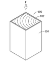
- the impact absorbing member 100 described in JP-A-2015-182560 includes a prismatic wood 102 and an outer cylinder 104 that houses the wood 102.
- the wood 102 is accommodated in the outer cylinder 104 so that the axial center direction of the annual ring coincides with the axial direction of the outer cylinder 104.
- both the wood 102 and the outer cylinder 104 are crushed in the axial direction, and the impact at the time of the vehicle collision is absorbed.
- the shock absorbing member 100 described above is configured to receive a collision load F at one end in the axial direction of a prismatic wood 102 or the like. That is, the area of the load input surface to which the collision load F is input is small. For this reason, for example, when the vehicle is used in a place where the collision site cannot be specifically identified, such as when the vehicle collides with a utility pole, the performance may not be exhibited.
- a first aspect of the present disclosure is a vehicle impact absorbing member that absorbs a collision load of a vehicle using deformation of wood, and is provided in a beam shape at an edge of a vehicle body, and an outer side surface is the collision
- a pair of upper and lower support woods that serve as a load input surface for receiving the load, and the axis of the annual ring extends along the load input surface, and the axis of the annual ring is perpendicular to the load input surface of the pair of upper and lower support woods
- the load input surface that receives the collision load is a load of the support wood, and is disposed between one end side and the other end side in the longitudinal direction of the support wood.
- the shock absorbing wood is located on the same surface as the input surface or inside the load input surface of the supporting wood.
- the pair of upper and lower support woods are provided in a beam shape at the edge of the vehicle body, and the outer surface serves as a load input surface that receives a collision load.
- the impact absorbing wood is sandwiched between a pair of upper and lower supporting woods and is arranged from one end side to the other end side in the longitudinal direction of the supporting wood.
- the load input surface of the shock absorbing wood is located on the same plane as the load input surface of the support wood or inside the load input surface of the support wood.
- the collision load can be reliably absorbed even in a place where the collision site cannot be specifically identified, such as when the vehicle collides with the utility pole.
- the axis of the annual ring of the shock-absorbing wood extends in the direction perpendicular to the load input surface of the supporting wood, that is, the direction of the assumed impact load, so that the impact-absorbing wood is crushed.
- a relatively large collision load can be absorbed.
- the impact-absorbing wood is restrained by being sandwiched from above and below by a pair of supporting woods in which the axis of the annual ring extends along the load input surface. For this reason, the shock absorbing wood can be restrained with high strength by the pair of upper and lower supporting woods.
- a plurality of prismatic shock-absorbing timbers are sandwiched between the pair of upper and lower supporting timbers in a side-by-side manner. For this reason, short prismatic wood can be used effectively.
- the load input surface of the shock absorbing wood is located on the inner side by a predetermined dimension than the load input surfaces of the pair of upper and lower support woods. For this reason, the collision load is first input to the load input surfaces of the pair of upper and lower support timbers, and after the pair of support timbers are crushed, the collision load is input to the load input surfaces of the impact absorbing timbers. After the collision load is input to the load input surface of the impact absorbing wood, both the impact absorbing wood and the pair of supporting woods are crushed. For this reason, in the initial stage when the collision load is applied, the load when the timber (supporting timber) is crushed is relatively small, and thereafter, the load by which the timber (shock absorbing timber + supporting timber) is crushed becomes large.
- the impact-absorbing wood is sandwiched and restrained by a pair of holding woods having the same direction of the support wood and the annual rings from both sides in the longitudinal direction of the support wood. For this reason, when the impact-absorbing wood receives a collision load and is crushed in the axial direction of the annual ring, it is difficult to deform in the radial direction of the annual ring.
- the pair of pressing wood includes a concave surface that is continuous with the load input surface of the impact absorbing wood.
- the shock-absorbing wood and the pair of upper and lower supporting woods are configured to be attachable along a vehicle bumper reinforcement extending in the vehicle width direction. For this reason, the impact absorbing member can absorb the collision load in the vehicle longitudinal direction.
- the impact-absorbing wood and the pair of upper and lower support woods are configured to be attachable along a vehicle rocker extending in the vehicle front-rear direction. For this reason, the impact absorbing member can absorb the collision load from the vehicle side surface direction.
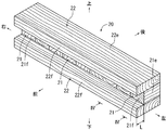
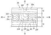
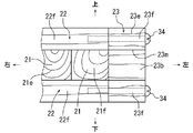
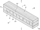
- FIG. 1 It is a schematic plan view of a vehicle front part provided with the impact-absorbing member which concerns on Embodiment 1 of this indication. It is a longitudinal cross-sectional view (II-II arrow sectional drawing of FIG. 1) of the bumper reinforcement to which the impact-absorbing member which concerns on this embodiment was attached. It is a model perspective view showing the impact-absorbing member which concerns on this embodiment. It is a partial front view (IV-IV arrow line view of FIG. 3) showing the said impact-absorbing member. It is a graph showing the relationship between the load added to an impact-absorbing member, and a deformation amount (stroke). It is a model perspective view showing the impact-absorbing member which concerns on the example 1 of a change.
- the shock absorbing member 20 according to the present embodiment is a member for reducing a collision load F applied to the vehicle 10 at the time of a vehicle front collision.
- the front and rear, right and left, and the top and bottom shown in the figure correspond to the front and rear, right and left, and top and bottom of the vehicle 10 to which the shock absorbing member 20 is attached.
- FIGS. 1 and 2 ⁇ About the outline of the front structure of the vehicle 10>
- side members 12 which are cylindrical skeleton members that extend in the vehicle front-rear direction, are provided at the front and rear sides of the vehicle 10.
- a front bumper 14 extending in the vehicle width direction is connected to the front end flange portion 12f (see FIG. 2) of the left and right side members 12.
- the front bumper 14 includes a bumper reinforcement 15 connected to the side member 12 and a bumper cover (not shown) that covers the bumper reinforcement 15 and the cushioning material.
- a beam-shaped impact absorbing member 20 is attached to the bumper reinforcement 15 of the front bumper 14. That is, the bumper reinforcement 15 corresponds to the edge of the vehicle body of the present disclosure.
- the bumper reinforcement 15 is formed in the shape of a square groove whose front side is opened by an upper plate portion 15u, a vertical plate portion 15w, and a lower plate portion 15d.
- the shock absorbing member 20 is housed in the rectangular groove of the bumper reinforcement 15.
- the upper plate portion 15u and the lower plate portion 15d of the bumper reinforcement 15 are formed with bolt holes 15h through which the bolts 30 for attaching the shock absorbing member 20 to the bumper reinforcement 15 are passed.
- the shock absorbing member 20 is a member that absorbs a collision load F at the time of a frontal collision of the vehicle, and is sandwiched between a pair of upper and lower support woods 22 and a pair of upper and lower support woods 22 as shown in FIGS. It is composed of a large number of impact absorbing woods 21 that are restrained by the above.
- the pair of upper and lower support woods 22 are thick plates formed in a beam shape with a constant width so that the axis of the annual ring 22e extends in the longitudinal direction (vehicle width direction (left-right direction)). It is configured.
- the front end surface in the width direction of the upper and lower pair of supporting woods 22 is a load input surface 22f that receives the collision load F.
- a conifer such as cedar or oak is preferably used.
- the shock absorbing wood 21 of the shock absorbing member 20 is a wood that mainly absorbs the collision load F. As shown in FIGS. 3 and 4, the shock absorbing wood 21 is formed in a prismatic shape having a length dimension that is smaller than the width dimension of the supporting wood 22 by a dimension L. The prismatic shock-absorbing wood 21 is arranged such that the axis of the shock-absorbing wood 21 extends in a direction perpendicular to the load input surface 22f of the supporting wood 22, that is, in the vehicle longitudinal direction. The axis of the annual ring 21e of the shock absorbing wood 21 is configured to extend in the vehicle front-rear direction along the axis of the shock absorbing wood 21.
- a large number of shock absorbing woods 21 are arranged in a line in the left-right direction with no gaps. Then, as shown in FIG. 3, the rear end surfaces of the large number of impact absorbing woods 21 are aligned so as to be flush with the rear end surfaces in the width direction of the pair of upper and lower support woods 22. Further, the front end surfaces of the large number of shock absorbing woods 21 are positioned at positions that enter the inside by a dimension L from the load input surfaces 22f (front end surfaces) of the pair of upper and lower support woods 22. The front end surfaces of the large number of shock absorbing woods 21 are load input surfaces 21f that receive the collision load F.
- conifers such as cedar or oak are preferably used in the same manner as the supporting wood 22.
- a pair of upper and lower support woods 22 and a large number of impact absorbing woods 21 are located at positions corresponding to the bolt holes 15h of the upper plate portion 15u and the lower plate portion 15d of the bumper reinforcement 15.
- Bolt holes 21h and 22h through which the bolts 30 are passed are formed.
- bolt holes 21 h and 22 h for the shock absorbing wood 21 and the supporting wood 22 are omitted.
- shock absorbing member 20 When the shock absorbing member 20 is attached to the bumper reinforcement 15, first, as shown in FIGS. 3 and 4, a large number of shock absorbing woods 21 are bonded to each other, and an aggregate of the shock absorbing woods 21 is attached. Adhere to a pair of upper and lower support woods 22. In this state, bolt holes 21h and 22h are formed at positions corresponding to the bolt holes 15h of the upper plate portion 15u and the lower plate portion 15d of the bumper reinforcement 15. Next, as shown in FIG. 2, the shock absorbing member 20 is accommodated between the upper plate portion 15 u and the lower plate portion 15 d of the bumper reinforcement 15.
- the bolt holes 15h of the bumper reinforcement 15 (upper plate portion 15u, lower plate portion 15d) and the bolt holes 21h and 22h of the shock absorbing wood 21 and the supporting wood 22 are aligned.
- the shock absorbing member 20 can be attached to the bumper reinforcement 15 by passing the bolt 30 through the bolt holes 15h, 21h, and 22h and screwing the nut 35 into the bolt 30 and tightening.
- the aggregate of the shock-absorbing wood 21 is bonded to the pair of upper and lower support woods 22 is shown, but the adhesion between the aggregate of the impact-absorbing wood 21 and the supporting wood 22 can be omitted. It is. Further, instead of forming the aggregate of impact absorbing wood 21 by bonding, it is also possible to form the aggregate of impact absorbing wood 21 using a fitting structure. Furthermore, when the number of shock absorbing woods 21 is small, it is possible to fix the impact absorbing woods 21 only by the tightening force between the bolts 30 and the nuts 35 by omitting the bonding or fitting process. .
- the collision load F is first input to the load input surfaces 22f of the pair of upper and lower support woods 22 of the shock absorbing member 20.
- the limit load F0 when the support wood 22 starts to be crushed is relatively small.
- the support woods 22 are arranged in the width direction (vehicle It will be crushed in the front-rear direction).
- the collision load F is input to the load input surface 21f of the impact absorption wood 21.
- the limit load Fx when the impact absorbing wood 21 starts to collapse is the limit load F0 when the supporting wood 22 starts to collapse. Is much bigger than.
- the shock absorbing wood 21 is crushed in the width direction (vehicle longitudinal direction) together with the supporting wood 22. That is, the impact load F is absorbed by the impact absorbing wood 21 and the supporting wood 22 being crushed.
- the limit load F0 when the pair of upper and lower support woods 22 starts to be crushed can be adjusted by increasing or decreasing the thickness dimension T2 of the support wood 22 (see FIG. 4). Further, the limit load Fx when the impact absorbing wood 21 starts to be crushed can be adjusted by increasing or decreasing the thickness dimension T1 of the impact absorbing wood 21.
- the pair of upper and lower support woods 22 are provided in a beam shape at the position of the bumper reinforcement 15 (the edge of the vehicle body), and the front end surface (outer surface) collides.
- the load input surface 22f receives the load F.
- the impact absorbing wood 21 is sandwiched between a pair of upper and lower supporting woods 22 and is disposed from one end side to the other end side in the longitudinal direction of the supporting wood 22.
- the load input surface 21f of the shock absorbing wood 21 is located inside the outer surface (load input surface 22f) of the support wood 22.
- the collision load F can be received in a wide range. Therefore, for example, when the vehicle 10 collides with the utility pole, the collision load F can be reliably absorbed even in a place where the collision site cannot be specifically identified.
- the axis of the annual ring 21e of the shock absorbing wood 21 extends in a direction perpendicular to the load input surface 22f of the supporting wood 22, that is, in the direction of the assumed collision load F.
- a relatively large collision load F can be absorbed.
- the shock absorbing wood 21 is restrained by being sandwiched from above and below by a pair of supporting woods 22 in which the axis of the annual ring 22e extends along the load input surface 22f. For this reason, the shock absorbing wood 21 is restrained with a large strength by the pair of upper and lower supporting woods 22.
- the impact absorbing member 20 is made of wood, for example, it is possible to reduce the weight as compared with the case of producing an impact absorbing member having an equal load absorbing performance with a light metal.
- ⁇ Modification 1> The above embodiment can be modified within the scope of the present disclosure.
- a large number of impact absorbing woods 21 are sandwiched between a pair of upper and lower supporting woods 22 is shown.
- a plurality of impact absorbing woods 21 can be sandwiched and restrained by a pair of left and right holding woods 23 from the left and right directions. It is. That is, the pair of left and right pressing woods 23 are provided so that the axis of the annual ring 23e is along the load input surface 23f, like the pair of upper and lower supporting woods 22.
- square grooves 23m are formed in front of the pair of left and right holding woods 23 in accordance with the positional relationship between the load input surfaces 22f of the pair of upper and lower support woods 22 and the load input surfaces 21f of the impact absorbing woods 21. Is formed.
- the bottom surface 23b of the square groove 23m of the pressing wood 23 is aligned with the load input surface 21f of the shock absorbing wood 21.
- the pair of left and right pressing woods 23 are fixed to the pair of upper and lower supporting woods 22 with wood screws 34 or the like. That is, the bottom surface 23b of the square groove 23m of the pressing wood 23 corresponds to the concave surface of the supporting wood of the present disclosure.
- the impact absorbing timber 21 is subjected to the collision load F. Therefore, when it collapses in the axial direction of the annual ring 21e, it becomes difficult to deform in the radial direction of the annual ring 21e.
- ⁇ Modification 2> an example in which the load input surface 21f of the impact load F in the large number of shock absorbing woods 21 is arranged on the inner side by the dimension L than the load input surface 22f of the impact load F in the upper and lower pair of support woods 22 is provided. Indicated. However, when it is not necessary to crush the impact absorbing member 20 in two stages, as shown in FIG. 8, the impact input surface 21f of the impact load F on the impact absorbing wood 21 and the impact on the pair of upper and lower supporting woods 22 are provided. It is also possible to provide the load input surface 22f of the load F flush with the surface. Further, as shown in FIG. 9, a large number of impact absorbing timbers 21 can be sandwiched and restrained by a pair of left and right pressing timbers 23 in addition to a pair of upper and lower supporting timbers 22.
- FIG. 10 schematically shows a state in which the vehicle 10 including the impact absorbing member 20 according to the modification 2 collides with the utility pole H.
- FIG. 11 schematically shows a state in which the load input surface 22f of the shock absorbing wood 21 of the shock absorbing member 20 and the load input surface 22f of the pair of upper and lower supporting woods 22 start to collapse at this time.
- shock absorbing member 20 is attached to the bumper reinforcement 15 in the present embodiment.
- the shock absorbing member 20 can be bolted to the lower side of the rocker (side sill). As a result, the side impact load of the vehicle 10 can be absorbed by the impact absorbing member 20.
Landscapes
- Engineering & Computer Science (AREA)
- Mechanical Engineering (AREA)
- Vibration Dampers (AREA)
- Body Structure For Vehicles (AREA)
Abstract
La présente invention comprend : une paire de matériaux ligneux de support supérieur et inférieur (22) qui sont disposés sous la forme de poutres sur des bords d'une carrosserie de véhicule, et qui comporte une surface latérale externe faisant office de surface d'entrée de charge (22f) pour recevoir une charge d'impact, et comporte des anneaux annulaires (22e) dont le centre axial s'étend le long de la surface d'entrée de charge (22f); et des matériaux ligneux d'absorption d'impact (21) qui, de sorte que le centre axial des anneaux annulaires (21e) de ceux-ci s'étende perpendiculairement par rapport à la surface d'entrée de charge (22f) des matériaux ligneux de support (22), sont pris en sandwich entre la paire de matériaux ligneux de support supérieur et inférieur (22), qui sont chacun disposés de sorte à s'étendre d'une extrémité à l'autre extrémité des matériaux ligneux de support (22) dans la direction longitudinale, et dans chacun desquels une surface d'entrée de charge (21f) destinée à recevoir une charge d'impact est située vers l'intérieur de la surface d'entrée de charge (22f) des matériaux ligneux de support (22).
Priority Applications (3)
| Application Number | Priority Date | Filing Date | Title |
|---|---|---|---|
| US16/496,448 US10953826B1 (en) | 2017-03-23 | 2017-12-05 | Vehicular shock-absorbing member |
| EP17902448.4A EP3604044B1 (fr) | 2017-03-23 | 2017-12-05 | Élément d'absorption des impacts pour des véhicules |
| CN201780088809.6A CN110431045B (zh) | 2017-03-23 | 2017-12-05 | 车辆的冲击吸收构件 |
Applications Claiming Priority (2)
| Application Number | Priority Date | Filing Date | Title |
|---|---|---|---|
| JP2017057474A JP6677201B2 (ja) | 2017-03-23 | 2017-03-23 | 車両の衝撃吸収部材 |
| JP2017-057474 | 2017-03-23 |
Publications (1)
| Publication Number | Publication Date |
|---|---|
| WO2018173377A1 true WO2018173377A1 (fr) | 2018-09-27 |
Family
ID=63584492
Family Applications (1)
| Application Number | Title | Priority Date | Filing Date |
|---|---|---|---|
| PCT/JP2017/043546 WO2018173377A1 (fr) | 2017-03-23 | 2017-12-05 | Élément d'absorption des impacts pour des véhicules |
Country Status (5)
| Country | Link |
|---|---|
| US (1) | US10953826B1 (fr) |
| EP (1) | EP3604044B1 (fr) |
| JP (1) | JP6677201B2 (fr) |
| CN (1) | CN110431045B (fr) |
| WO (1) | WO2018173377A1 (fr) |
Cited By (2)
| Publication number | Priority date | Publication date | Assignee | Title |
|---|---|---|---|---|
| JP2020059441A (ja) * | 2018-10-11 | 2020-04-16 | トヨタ自動車株式会社 | バンパリインフォースメント構造及びバンパリインフォースメントの製造方法 |
| EP3696439A1 (fr) * | 2019-02-18 | 2020-08-19 | Toyota Shatai Kabushiki Kaisha | Élément d'absorption de chocs et son procédé de fabrication |
Families Citing this family (7)
| Publication number | Priority date | Publication date | Assignee | Title |
|---|---|---|---|---|
| JP6729528B2 (ja) * | 2017-09-25 | 2020-07-22 | トヨタ車体株式会社 | 衝撃吸収部材、及びその製造方法 |
| JP6863219B2 (ja) * | 2017-10-13 | 2021-04-21 | トヨタ自動車株式会社 | 車両側部構造 |
| JP6796244B2 (ja) | 2017-11-15 | 2020-12-09 | トヨタ車体株式会社 | 車両の衝撃吸収部材 |
| CN109849828B (zh) * | 2019-03-28 | 2021-04-23 | 河南理工大学 | 一种用于汽车碰撞的缓冲减振吸能防护板 |
| JP7325353B2 (ja) * | 2020-02-12 | 2023-08-14 | 株式会社豊田中央研究所 | 衝撃吸収機構 |
| US11097677B1 (en) * | 2020-02-12 | 2021-08-24 | Mccue Corporation | Wooden bumper assembly |
| DE102022102534A1 (de) | 2022-02-03 | 2023-08-17 | Bayerische Motoren Werke Aktiengesellschaft | Vorbaustruktur sowie Achsträger für eine selbsttragende Karosserie eines Personenkraftwagens |
Citations (4)
| Publication number | Priority date | Publication date | Assignee | Title |
|---|---|---|---|---|
| US4671550A (en) * | 1985-07-01 | 1987-06-09 | Arpi Co. | Bumper beam |
| US6062632A (en) * | 1998-03-20 | 2000-05-16 | Solectria Corporation | Vehicle body collision energy absorption system |
| JP2004322861A (ja) * | 2003-03-04 | 2004-11-18 | Jsp Corp | バンパー構造 |
| JP2015182560A (ja) | 2014-03-24 | 2015-10-22 | トヨタ車体株式会社 | 車両の衝撃吸収構造 |
Family Cites Families (12)
| Publication number | Priority date | Publication date | Assignee | Title |
|---|---|---|---|---|
| US1380615A (en) * | 1920-09-09 | 1921-06-07 | Elverton W Weaver | Resilient bumper-bar |
| BRPI0409466A (pt) * | 2003-04-17 | 2006-04-18 | Energy Absorption System | montagem para atenuador montado em caminhão |
| US8684427B2 (en) * | 2010-10-29 | 2014-04-01 | Sabic Innovative Plastics Ip B.V. | Reinforced plastic energy absorber system |
| JP5545259B2 (ja) * | 2010-12-01 | 2014-07-09 | トヨタ車体株式会社 | 衝撃吸収部材 |
| BR112012026522B1 (pt) * | 2011-03-15 | 2019-10-01 | Toyota Jidosha Kabushiki Kaisha | Estrutura de pára-choque |
| EP2786903B1 (fr) * | 2011-11-29 | 2018-03-14 | Toyota Shatai Kabushiki Kaisha | Élément absorbeur de choc pour véhicule |
| JP2015155704A (ja) * | 2012-04-24 | 2015-08-27 | トヨタ車体株式会社 | 衝撃吸収機構 |
| JP2013231484A (ja) * | 2012-05-01 | 2013-11-14 | Toyota Auto Body Co Ltd | 衝撃吸収機構 |
| EP2921354B1 (fr) * | 2012-11-19 | 2023-06-28 | Toyota Shatai Kabushiki Kaisha | Ensemble d'un élément de reception de charge d'un véhicule, comprenant un élément de chassis du véhicule et un mécanisme absorbeur de chocs disposé entre les deux |
| JP6120455B2 (ja) * | 2015-06-05 | 2017-04-26 | 本田技研工業株式会社 | 車両用バンパービームおよび車両用バンパービームの製造方法 |
| JP6354677B2 (ja) * | 2015-06-25 | 2018-07-11 | トヨタ車体株式会社 | 車両の衝撃吸収構造 |
| JP6798457B2 (ja) * | 2017-09-15 | 2020-12-09 | トヨタ自動車株式会社 | バンパリインフォースメント |
-
2017
- 2017-03-23 JP JP2017057474A patent/JP6677201B2/ja active Active
- 2017-12-05 EP EP17902448.4A patent/EP3604044B1/fr active Active
- 2017-12-05 CN CN201780088809.6A patent/CN110431045B/zh active Active
- 2017-12-05 WO PCT/JP2017/043546 patent/WO2018173377A1/fr unknown
- 2017-12-05 US US16/496,448 patent/US10953826B1/en active Active
Patent Citations (4)
| Publication number | Priority date | Publication date | Assignee | Title |
|---|---|---|---|---|
| US4671550A (en) * | 1985-07-01 | 1987-06-09 | Arpi Co. | Bumper beam |
| US6062632A (en) * | 1998-03-20 | 2000-05-16 | Solectria Corporation | Vehicle body collision energy absorption system |
| JP2004322861A (ja) * | 2003-03-04 | 2004-11-18 | Jsp Corp | バンパー構造 |
| JP2015182560A (ja) | 2014-03-24 | 2015-10-22 | トヨタ車体株式会社 | 車両の衝撃吸収構造 |
Non-Patent Citations (1)
| Title |
|---|
| See also references of EP3604044A4 |
Cited By (4)
| Publication number | Priority date | Publication date | Assignee | Title |
|---|---|---|---|---|
| JP2020059441A (ja) * | 2018-10-11 | 2020-04-16 | トヨタ自動車株式会社 | バンパリインフォースメント構造及びバンパリインフォースメントの製造方法 |
| JP7095543B2 (ja) | 2018-10-11 | 2022-07-05 | トヨタ自動車株式会社 | バンパリインフォースメント構造及びバンパリインフォースメントの製造方法 |
| EP3696439A1 (fr) * | 2019-02-18 | 2020-08-19 | Toyota Shatai Kabushiki Kaisha | Élément d'absorption de chocs et son procédé de fabrication |
| US11371577B2 (en) | 2019-02-18 | 2022-06-28 | Toyota Shatai Kabushiki Kaisha | Shock absorbing member and method of manufacturing the same |
Also Published As
| Publication number | Publication date |
|---|---|
| JP6677201B2 (ja) | 2020-04-08 |
| JP2018158671A (ja) | 2018-10-11 |
| CN110431045B (zh) | 2022-11-11 |
| US10953826B1 (en) | 2021-03-23 |
| EP3604044A1 (fr) | 2020-02-05 |
| US20210107417A1 (en) | 2021-04-15 |
| CN110431045A (zh) | 2019-11-08 |
| EP3604044A4 (fr) | 2020-10-14 |
| EP3604044B1 (fr) | 2021-12-01 |
Similar Documents
| Publication | Publication Date | Title |
|---|---|---|
| WO2018173377A1 (fr) | Élément d'absorption des impacts pour des véhicules | |
| US8215705B2 (en) | Shock-absorber assembly and corresponding motor vehicle | |
| US20180281863A1 (en) | Front chassis structure for automobile | |
| JP5929256B2 (ja) | 車体構造 | |
| JP4621883B2 (ja) | 車両の衝撃吸収部材 | |
| CN101626943A (zh) | 具有加强泡沫的行人安全汽车发动机罩 | |
| JP2019104463A (ja) | 車両の衝撃吸収構造 | |
| JP4365232B2 (ja) | 車両の衝撃吸収部材 | |
| JP4762665B2 (ja) | 車体フレーム構造 | |
| JP2005162049A (ja) | 車両の衝撃吸収部材 | |
| JP2019073097A (ja) | 車両側部構造 | |
| JP5337117B2 (ja) | 後部車体構造 | |
| KR101603147B1 (ko) | 차량용 범퍼 빔 유닛 | |
| WO2013105438A1 (fr) | Structure absorbant les impacts pour un véhicule | |
| KR20210071182A (ko) | 차량용 차체 | |
| US12084113B2 (en) | Vehicle front structure | |
| US20230144195A1 (en) | Vehicle Center Frame Module | |
| WO2020153473A1 (fr) | Élément de structure et structure de carrosserie de véhicule | |
| KR101328396B1 (ko) | 차량용 범퍼빔 유닛 | |
| WO2018088099A1 (fr) | Structure d'absorption des chocs pour véhicules | |
| CN216994514U (zh) | 副车架防撞梁组件及车辆 | |
| CN221623696U (zh) | 吸能盒安装总成以及车辆 | |
| JP2019104464A (ja) | 車両の衝撃吸収構造 | |
| KR20240098381A (ko) | 배터리 케이스의 사이드 프레임 | |
| JPWO2010058467A1 (ja) | 車体構造および車両用バンパ |
Legal Events
| Date | Code | Title | Description |
|---|---|---|---|
| 121 | Ep: the epo has been informed by wipo that ep was designated in this application |
Ref document number: 17902448 Country of ref document: EP Kind code of ref document: A1 |
|
| NENP | Non-entry into the national phase |
Ref country code: DE |
|
| ENP | Entry into the national phase |
Ref document number: 2017902448 Country of ref document: EP Effective date: 20191023 |