WO2018163968A1 - 発泡粒子成形体 - Google Patents
発泡粒子成形体 Download PDFInfo
- Publication number
- WO2018163968A1 WO2018163968A1 PCT/JP2018/007850 JP2018007850W WO2018163968A1 WO 2018163968 A1 WO2018163968 A1 WO 2018163968A1 JP 2018007850 W JP2018007850 W JP 2018007850W WO 2018163968 A1 WO2018163968 A1 WO 2018163968A1
- Authority
- WO
- WIPO (PCT)
- Prior art keywords
- molded body
- particle molded
- particles
- foamed
- foamed particle
- Prior art date
Links
Images


Classifications
-
- C—CHEMISTRY; METALLURGY
- C08—ORGANIC MACROMOLECULAR COMPOUNDS; THEIR PREPARATION OR CHEMICAL WORKING-UP; COMPOSITIONS BASED THEREON
- C08J—WORKING-UP; GENERAL PROCESSES OF COMPOUNDING; AFTER-TREATMENT NOT COVERED BY SUBCLASSES C08B, C08C, C08F, C08G or C08H
- C08J9/00—Working-up of macromolecular substances to porous or cellular articles or materials; After-treatment thereof
- C08J9/22—After-treatment of expandable particles; Forming foamed products
- C08J9/228—Forming foamed products
- C08J9/232—Forming foamed products by sintering expandable particles
-
- B—PERFORMING OPERATIONS; TRANSPORTING
- B29—WORKING OF PLASTICS; WORKING OF SUBSTANCES IN A PLASTIC STATE IN GENERAL
- B29C—SHAPING OR JOINING OF PLASTICS; SHAPING OF MATERIAL IN A PLASTIC STATE, NOT OTHERWISE PROVIDED FOR; AFTER-TREATMENT OF THE SHAPED PRODUCTS, e.g. REPAIRING
- B29C44/00—Shaping by internal pressure generated in the material, e.g. swelling or foaming ; Producing porous or cellular expanded plastics articles
- B29C44/02—Shaping by internal pressure generated in the material, e.g. swelling or foaming ; Producing porous or cellular expanded plastics articles for articles of definite length, i.e. discrete articles
-
- B—PERFORMING OPERATIONS; TRANSPORTING
- B29—WORKING OF PLASTICS; WORKING OF SUBSTANCES IN A PLASTIC STATE IN GENERAL
- B29C—SHAPING OR JOINING OF PLASTICS; SHAPING OF MATERIAL IN A PLASTIC STATE, NOT OTHERWISE PROVIDED FOR; AFTER-TREATMENT OF THE SHAPED PRODUCTS, e.g. REPAIRING
- B29C44/00—Shaping by internal pressure generated in the material, e.g. swelling or foaming ; Producing porous or cellular expanded plastics articles
- B29C44/34—Auxiliary operations
- B29C44/36—Feeding the material to be shaped
- B29C44/38—Feeding the material to be shaped into a closed space, i.e. to make articles of definite length
- B29C44/44—Feeding the material to be shaped into a closed space, i.e. to make articles of definite length in solid form
- B29C44/445—Feeding the material to be shaped into a closed space, i.e. to make articles of definite length in solid form in the form of expandable granules, particles or beads
-
- C—CHEMISTRY; METALLURGY
- C08—ORGANIC MACROMOLECULAR COMPOUNDS; THEIR PREPARATION OR CHEMICAL WORKING-UP; COMPOSITIONS BASED THEREON
- C08J—WORKING-UP; GENERAL PROCESSES OF COMPOUNDING; AFTER-TREATMENT NOT COVERED BY SUBCLASSES C08B, C08C, C08F, C08G or C08H
- C08J9/00—Working-up of macromolecular substances to porous or cellular articles or materials; After-treatment thereof
- C08J9/16—Making expandable particles
- C08J9/18—Making expandable particles by impregnating polymer particles with the blowing agent
-
- B—PERFORMING OPERATIONS; TRANSPORTING
- B29—WORKING OF PLASTICS; WORKING OF SUBSTANCES IN A PLASTIC STATE IN GENERAL
- B29K—INDEXING SCHEME ASSOCIATED WITH SUBCLASSES B29B, B29C OR B29D, RELATING TO MOULDING MATERIALS OR TO MATERIALS FOR MOULDS, REINFORCEMENTS, FILLERS OR PREFORMED PARTS, e.g. INSERTS
- B29K2075/00—Use of PU, i.e. polyureas or polyurethanes or derivatives thereof, as moulding material
-
- C—CHEMISTRY; METALLURGY
- C08—ORGANIC MACROMOLECULAR COMPOUNDS; THEIR PREPARATION OR CHEMICAL WORKING-UP; COMPOSITIONS BASED THEREON
- C08J—WORKING-UP; GENERAL PROCESSES OF COMPOUNDING; AFTER-TREATMENT NOT COVERED BY SUBCLASSES C08B, C08C, C08F, C08G or C08H
- C08J2203/00—Foams characterized by the expanding agent
- C08J2203/06—CO2, N2 or noble gases
-
- C—CHEMISTRY; METALLURGY
- C08—ORGANIC MACROMOLECULAR COMPOUNDS; THEIR PREPARATION OR CHEMICAL WORKING-UP; COMPOSITIONS BASED THEREON
- C08J—WORKING-UP; GENERAL PROCESSES OF COMPOUNDING; AFTER-TREATMENT NOT COVERED BY SUBCLASSES C08B, C08C, C08F, C08G or C08H
- C08J2203/00—Foams characterized by the expanding agent
- C08J2203/22—Expandable microspheres, e.g. Expancel®
-
- C—CHEMISTRY; METALLURGY
- C08—ORGANIC MACROMOLECULAR COMPOUNDS; THEIR PREPARATION OR CHEMICAL WORKING-UP; COMPOSITIONS BASED THEREON
- C08J—WORKING-UP; GENERAL PROCESSES OF COMPOUNDING; AFTER-TREATMENT NOT COVERED BY SUBCLASSES C08B, C08C, C08F, C08G or C08H
- C08J2205/00—Foams characterised by their properties
- C08J2205/04—Foams characterised by their properties characterised by the foam pores
- C08J2205/052—Closed cells, i.e. more than 50% of the pores are closed
-
- C—CHEMISTRY; METALLURGY
- C08—ORGANIC MACROMOLECULAR COMPOUNDS; THEIR PREPARATION OR CHEMICAL WORKING-UP; COMPOSITIONS BASED THEREON
- C08J—WORKING-UP; GENERAL PROCESSES OF COMPOUNDING; AFTER-TREATMENT NOT COVERED BY SUBCLASSES C08B, C08C, C08F, C08G or C08H
- C08J2300/00—Characterised by the use of unspecified polymers
- C08J2300/22—Thermoplastic resins
-
- C—CHEMISTRY; METALLURGY
- C08—ORGANIC MACROMOLECULAR COMPOUNDS; THEIR PREPARATION OR CHEMICAL WORKING-UP; COMPOSITIONS BASED THEREON
- C08J—WORKING-UP; GENERAL PROCESSES OF COMPOUNDING; AFTER-TREATMENT NOT COVERED BY SUBCLASSES C08B, C08C, C08F, C08G or C08H
- C08J2300/00—Characterised by the use of unspecified polymers
- C08J2300/26—Elastomers
-
- C—CHEMISTRY; METALLURGY
- C08—ORGANIC MACROMOLECULAR COMPOUNDS; THEIR PREPARATION OR CHEMICAL WORKING-UP; COMPOSITIONS BASED THEREON
- C08J—WORKING-UP; GENERAL PROCESSES OF COMPOUNDING; AFTER-TREATMENT NOT COVERED BY SUBCLASSES C08B, C08C, C08F, C08G or C08H
- C08J2375/00—Characterised by the use of polyureas or polyurethanes; Derivatives of such polymers
- C08J2375/04—Polyurethanes
Definitions
- thermoplastic elastomer a thermoplastic elastomer may be abbreviated as “TPE”.
- thermoplastic elastomer foamed particle molded body may be simply referred to as “foamed particle molded body”.
- Thermoplastic elastomers such as urethane-based thermoplastic elastomers (TPU) exhibit properties close to that of vulcanized rubber, and are excellent in flexibility and impact resilience. They are cushioning materials, vibration-proofing materials, sports equipment, and automotive parts. It is used for various purposes.
- the foamed molded body obtained by foaming this TPE can be reduced in weight while maintaining excellent properties such as flexibility and rebound resilience. Be expected.
- the foamed molded body of TPE can be manufactured by methods such as extrusion foaming, press foaming, and in-mold molding using foamed particles.
- a foamed molded body of TPE for example, a foamed particle molded body described in Patent Document 1 is known as a conventional technique.
- the conventional TPE expanded particle molded body has a problem that it takes a long time to recover the shape before compression after the molded body is compressed and the compression is finished.
- the problem to be solved by the present invention is to provide a TPE expanded particle molded article having good shape recoverability in a short time after compression.
- the present invention is as follows.
- [1] A foamed particle molded body obtained by in-mold molding of thermoplastic elastomer foamed particles, wherein the foamed particle molded body has voids between the foamed particles, and the density of the foamed particle molded body is 150 to 300 kg / m. 3 and the porosity is 10 to 70 vol%, PP bead molding.
- [2] Foamed particle molding according to the above [1], wherein the compression set after 30 minutes of completion of compression of the foamed particle molded body is 7% or less in compression set measurement at 23 ° C. based on JIS K6767: 1999. body.
- thermoplastic elastomer constituting the foamed particle molded body is a urethane-based thermoplastic elastomer having a type A durometer hardness of 95 or less. Molded body.
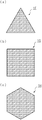
- FIG. 1 is a diagram showing an example of the shape of expanded particles that can increase the porosity of a TPE expanded particle molded body.
- FIG. 2 is a diagram showing an example of the shape of the expanded particles that can increase the porosity of the TPE expanded particle molded body.
- FIG. 3 is a diagram showing an example of the shape of the expanded particles that can increase the porosity of the TPE expanded particle molded body.
- FIG. 4 is a diagram showing an example of the shape of the expanded particles that can increase the porosity of the TPE expanded particle molded body.
- FIG. 5 is a diagram showing an example of the shape of the expanded particles that can increase the porosity of the TPE expanded particle molded body.
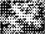
- FIG. 6 is a photomicrograph of expanded particles having a cross-shaped cross section used in the production of the expanded particle molded body of Example 1.
- FIG. 7 is a photomicrograph of expanded particles having a cross-shaped cross section used for the production of the expanded particle molded body of Example 2.
- FIG. 8 is a photomicrograph of expanded particles having a star shape in cross section used in the production of the expanded particle molded bodies of Examples 3 to 5.
- thermoplastic elastomer foamed particle molded body is a foamed particle molded body formed by molding thermoplastic elastomer foamed particles in a mold and has a space between the foamed particles. Has a density of 150 to 300 kg / m 3 and a porosity of 10 to 70% by volume.
- thermoplastic elastomer constituting the TPE expanded particle molded body of the present invention is not particularly limited.
- TPO olefin thermoplastic elastomer
- TPS styrene thermoplastic elastomer
- TPU urethane thermoplastic elastomer
- the olefin-based thermoplastic elastomer means a thermoplastic elastomer having a polyolefin such as polypropylene or polyethylene as a hard segment and a rubber component such as ethylene-propylene rubber (EPM) as a soft segment.
- TPO is generally roughly classified into a blend type of polyolefin and a rubber component, a dynamic crosslinking type, and a polymerization type.
- TPO has a structure in which ethylene-propylene rubber (EPM) is dispersed in polypropylene, a structure in which ethylene-propylene-diene rubber (EPDM) is dispersed in polypropylene, ethylene, And a random copolymer of olefin and ⁇ -olefin, a block copolymer of polyethylene block and ethylene / ⁇ -olefin copolymer block, and the like.
- EPM ethylene-propylene rubber
- EPDM ethylene-propylene-diene rubber
- Styrenic thermoplastic elastomer means a thermoplastic elastomer having polystyrene as a hard segment and a conjugated diene polymer, a completely hydrogenated product or a partially hydrogenated product of the polymer as a soft segment.
- TPS includes styrene-butadiene-styrene block copolymer (SBS), styrene-ethylene-butylene-styrene copolymer (SEBS), which is a complete hydrogenated product of SBS, and partial hydrogenated product of SBS.
- SBBS styrene-butadiene-butylene-styrene
- SIS styrene-isoprene-styrene block copolymer
- SEPS styrene-ethylene-propylene-styrene
- thermoplastic elastomer A urethane-based thermoplastic elastomer (TPU) is a heat having a structure in which a soft segment containing a long-chain polyol and a hard segment obtained by polymerizing a chain extender such as a short-chain glycol and a diisocyanate with a urethane bond are block copolymerized. It is a plastic elastomer.
- thermoplastic elastomer a urethane-based thermoplastic elastomer
- TPU thermoplastic elastomer
- the shape of the TPU raw material particles is easily maintained (difficult to spheroidize), and foamed particles having a desired shape are easily obtained.
- TPU foam particles are excellent in fusion property at the time of in-mold molding, they can be fused without excessive secondary foaming at the time of in-mold molding. In-mold molding can be performed while leaving voids between the expanded particles.
- the size of the gap between the foamed particles when filled in the mold can be controlled to be small. That is, when the TPE constituting the expanded particles is TPU, it becomes easy to control the porosity of the expanded expanded particles to a desired value.
- TPU generally includes ester-based TPU and ether-based TPU depending on the type of long-chain polyol, and affects the properties of the obtained TPU.
- the long-chain polyol that is a constituent element of the ester-based TPU include a compound obtained by a condensation reaction between a polyhydric alcohol and a dibasic acid, and a lactone-based ester polyol.
- specific examples of the polyhydric alcohol include ethylene glycol, propylene glycol, butanediol, butenediol, hexanediol, pentanediol, neopentyldiol, pentanediol and the like.
- dibasic acid examples include adipic acid, sebacic acid, azelaic acid, terephthalic acid, isophthalic acid, maleic acid and the like.
- long-chain polyol that is a constituent element of the ether-based TPU examples include polyethylene glycol, polypropylene ether glycol, polytetramethylene ether glycol, polyhexamethylene ether glycol, and the like.
- examples of the short chain glycol include ethylene glycol, propylene glycol, butanediol, butenediol, pentanediol, neopentyl glycol, hexanediol, cyclohexanediol, diethylene glycol, diethanolamine, and triethanolamine.
- examples of the diisocyanate include tolylene diisocyanate (TDI), diphenylmethane diisocyanate (MDI), hexamethylene diisocyanate, naphthalene diisocyanate, isophorone diisocyanate, xylene diisocyanate and the like.
- TPU components are not particularly limited.
- the constituent elements of the TPU are appropriately selected according to the physical properties required for the foamed particle molded body.
- a single TPU selected from a single component may be used, or a mixed species selected from two or more components such as a long-chain polyol, a short-chain glycol, and a diisocyanate.
- a TPU may be used.
- the TPU may be any of the ether-based TPU and the ester-based TPU described above, but from the viewpoint of excellent surface appearance and fusion property of the obtained thermoplastic polyurethane foam particle molded body, the TPU foam of the present invention.
- the TPU constituting the particle compact is preferably mainly composed of ether-based TPU, and more preferably composed only of ether-based TPU.
- the foamed particle molded body of the present invention may contain a thermoplastic resin depending on the purpose within the limit that does not impair the effects of the present invention.
- the thermoplastic resin include polyolefin resins and polystyrene resins.
- the content of these thermoplastic resins in the polymer component constituting the expanded particle molded body is preferably 30% by weight or less, more preferably 20% by weight or less, and further preferably 10% by weight or less.
- the polymer component consists only of TPE (the content of TPE in the polymer component is 100% by weight).
- the type A durometer hardness of the polymer component containing TPU is preferably 95 or less. If the hardness is 95 or less, it is possible to obtain a foamed particle molded article having excellent fusion properties without excessively increasing the steam pressure (molding pressure) during in-mold molding. Can be suppressed, and the porosity of the foamed particle molded body can be easily adjusted. From this viewpoint, the hardness is more preferably 92 or less, still more preferably 90 or less, and particularly preferably 88 or less.
- the lower limit is not particularly limited from the viewpoint of fusibility, but if the hardness is too low, depending on the molding conditions and the shape of the molded body, the molded body is released from the mold and then molded. Since so-called sink marks that the body significantly contracts and deforms easily occur, the hardness is more preferably 70 or more, still more preferably 80 or more, and particularly preferably 85 or more.
- type A durometer hardness means durometer hardness (HDA) measured using a type A durometer based on JIS K7215: 1986.
- the foamed particle molded body of the present invention has the following characteristics.
- the density of the foamed particle molded body of the present invention is 150 to 300 kg / m 3 . If the molded body density is less than 150 kg / m 3 , it may take a long time to recover the shape before compression after compressing the foamed particle molded body. On the other hand, if the density of the molded body is larger than 300 kg / m 3, it may take a long time to recover the shape before compression after the foamed particle molded body is compressed. From the above viewpoint, the density of the foamed particle molded body is preferably 170 to 280 kg / m 3 , more preferably 190 to 260 kg / m 3 .
- the foamed particle molded body of the present invention has voids, and the void ratio is 10 to 70% by volume.
- the porosity of the foamed particle molded body is less than 10% by volume, it may take a long time to recover the shape before compression after the foamed particle molded body is compressed.
- the porosity of the TPE expanded particle molded body is larger than 70% by volume, the fusion property between the expanded particles of the expanded particle molded body may be poor.
- the porosity of the foamed particle molded body is preferably 13 to 65% by volume, more preferably 15 to 60% by volume, and still more preferably 20 to 50% by volume.
- the porosity of the foamed particle molded body can be changed by changing the shape of the foamed particle and changing the bulk of the foamed particle when filling the mold (changing the apparent density to the bulk density of the foamed particle), It can be controlled by controlling the secondary foamability of the foamed particles during in-mold molding.
- the voids of the TPE expanded particle molded body communicate with each other.
- the foamed particle molded body can be suitably used as a breathable material, a water permeable material, a sound deadening material, a cushioning material, a lightweight material, and the like.
- FIG. 1 is a diagram illustrating an example of a columnar foamed particle having a cross-sectional shape formed of three or more protrusions extending outward from the axis A. The cross-sectional shape is determined from the axis A.
- FIG. 4 is a perspective view of columnar foam particles having a shape (hereinafter also referred to as a cross shape) consisting of four projecting portions 11a to 14a extending outward.
- FIG. 2 is also a diagram illustrating an example of a columnar foamed particle having a cross-sectional shape including three or more projecting portions extending outward from the axis A.
- FIG. 6 is a perspective view of columnar foam particles having a shape composed of six projecting portions 11b to 16b extending outward from B (hereinafter sometimes referred to as a star shape).
- the foamed particles having the shapes shown in FIGS. 1 and 2 can be obtained, for example, as follows. TPE and a predetermined additive are supplied to an extruder, and these are heated and kneaded to obtain a melt-kneaded product. Then, the melt-kneaded product is extruded into water from a small hole of a die having the same shape as the cross-sectional shape of the foamed particles attached to the tip of the extruder and cut to obtain raw material particles.
- the melt-kneaded product is extruded into a strand shape from a die hole having a die shape similar to the cross-sectional shape of a desired expanded particle attached to the tip of the extruder, and the strand is cooled and cut to obtain a raw material. Get particles. By foaming the obtained raw material particles, foamed particles having a shape as shown in FIGS. 1 and 2 can be obtained.
- the number of the protrusion parts of the expanded particle which can raise the porosity of an expanded particle molded object is 3 or more, it will not be limited to the expanded particle shown in FIG.1 and FIG.2.
- the number of protrusions 11c to 13c extending outward from the axis C in the cross-sectional shape may be three, or FIG.
- the number of protrusions 11d to 15d extending outward from the axis D in the cross-sectional shape may be five, or the columnar foam shown in FIG.
- the number of protrusions 11e to 18e extending outward from the axis E in the cross-sectional shape may be eight.
- the number of protrusions extending outward from the shaft in the cross-sectional shape of the columnar foam particles may be nine or more.
- the number of protrusions is preferably 3 to 8, more preferably 4 to 6.
- the foamed particles capable of increasing the porosity of the foamed particle molded body may be columnar foamed particles having a polygonal cross-sectional shape.
- it may be a foamed particle having a triangular cross-sectional shape like a columnar foamed particle 1F shown in FIG. 4 (a), or a cross-sectional shape like a columnar foamed particle 1G shown in FIG. 4 (b).
- It may be a foamed particle having a quadrangular shape, or may be a foamed particle having a hexagonal cross section as in the columnar foamed particle 1H shown in FIG.
- the expanded particle whose cross-sectional shape is a polygon more than a heptagon may be sufficient.
- the foamed particles that can increase the porosity of the foamed particle molded body are foamed particles having a circular, elliptical, or polygonal cross-sectional shape having three or more protrusions extending outward from the shaft. May be.
- the cross-sectional shape is a columnar foamed particle that is a triangle having six projecting portions 11j to 16j extending outward from the axis J.
- the cross-sectional shape is a columnar foamed particle having a quadrangular shape having six projecting portions 11k to 16k extending outward from the axis K.
- the cross-sectional shape is a columnar foam having a circular shape having six projecting portions 11m to 16m extending outward from the axis M. It may be a particle.
- the cross-sectional shape is an elliptical shape having five or seven or more protruding portions extending outward from the axis, a quadrangular shape, a pentagonal shape, or a columnar shape having a number of corners of seven or more.
- the expanded particles may be used.
- the foamed particles have a shape composed of three or more protrusions whose cross-sectional shape extends outward from the shaft. It is preferable that the foamed columnar particles have a circular shape, an elliptical shape, or a polygonal shape having three or more protrusions whose cross-sectional shape extends outward from the shaft.
- the foamed particle molded body of the present invention has voids between the foamed particles, when the foamed particle molded body is compressed, first, the voids of the foamed particle molded body are crushed. Is prevented from being crushed. For this reason, it becomes difficult for the gas in the bubbles of the foamed particle molded body to escape. And since the thermoplastic elastomer is difficult to plastically deform in the normal temperature range, if the foamed particle molded body has voids, it is considered that the time until the foamed particle molded body is restored to the shape before compression is reduced. .
- the density and porosity of the foamed particle molded body are determined as follows. First, a foamed particle molded body that has been allowed to stand for 24 hours or more in an environment of a temperature of 23 ° C. and a relative humidity of 50% is cut into a rectangular parallelepiped sample (molded skin is removed) of an appropriate size. And the apparent volume of each sample is calculated
- Porosity (volume%) [(HI) ⁇ H] ⁇ 100 (1)
- the foamed particle molded body of the present invention preferably has a compression set of 7% or less, more preferably 6% or less, and still more preferably 4% or less.
- the lower limit of the compression set is not particularly limited, but is about 0.1%, for example.
- the compression set is the strain of the foamed particle molded body 30 minutes after the end of compression of the foamed particle molded body in the compression set measurement at 23 ° C. based on JIS K6767: 1999. If it is in the above range, it is excellent in recoverability of the shape after the foamed particle molded body is compressed, so that it is suitable for uses such as a seat cushion material, a sports pad material, and a shoe sole material.
- the tensile strength at break of the foamed particle molded body of the present invention is preferably 0.1 MPa or more. If the tensile strength at break of the foamed particle molded body is 0.1 MPa or more, it indicates that the fusibility between the foamed particles of the foamed particle molded body is good, and has excellent durability, a seat cushion material, It can be applied to uses such as sports pad materials, sole (sole) members, insole members and the like. From the above viewpoint, the tensile strength at break of the foamed particle molded body is more preferably 0.3 MPa or more, further preferably 0.4 MPa or more, and particularly preferably 0.5 MPa or more. The upper limit is not particularly limited, but is about 3.0 MPa. In addition, the tensile strength at the time of the fracture
- the rebound resilience of the foamed particle molded body of the present invention is preferably 50% or more. If the rebound resilience of the foamed particle molded body is less than 50%, it may be difficult to obtain a foamed particle molded body having excellent resilience that is used as a sole member or the like. From the above viewpoint, the rebound resilience of the foamed particle molded body is more preferably 50 to 85%, still more preferably 54 to 85%. The rebound resilience of the foamed particle molded body can be measured based on JIS K6255: 2013.
- the rebound resilience of the thermoplastic elastomer constituting the foamed particle molded body of the present invention is preferably 30 to 50%. Usually, in order to shorten the time until the molded body is restored after being compressed, it is necessary to increase the rebound resilience of the molded body. However, in the case of the foamed particle molded body of the present invention, even when the rebound resilience of the thermoplastic elastomer constituting the molded body is low, the time until the molded body is restored to the shape before compression after the compression is short.
- the rebound resilience of the thermoplastic elastomer constituting the molded body can be measured according to JIS K6255: 2013. The test sample can be produced as follows. First, the raw material particles are heat-pressed at 200 ° C.
- a sample having a length of 30 mm, a width of 30 mm, and a thickness of 12.5 mm is cut out from the center of the sheet.
- a Shob type impact resilience tester “RT-90” manufactured by Kobunshi Keiki Co., Ltd.
- RT-90 manufactured by Kobunshi Keiki Co., Ltd.
- the closed cell ratio of the foamed particle molded body of the present invention is preferably 60% or more.
- each bubble is independently formed, and thus the resilience to external force is more easily exhibited.
- the upper limit of the closed cell ratio of the foamed particle molded body is 100%.
- the closed cell ratio of the foamed particle molded body is more preferably 70 to 100%, and still more preferably 80 to 100%.
- the closed cell ratio of the foamed particle molded body is the ratio of the volume of closed cells to the volume of bubbles contained in the foamed particles constituting the foamed particle molded body (total volume of closed cells and open cells). In accordance with Procedure C described in ASTM-D2856-70, it can be obtained using an air comparison type hydrometer “930” (manufactured by Toshiba Beckman Co., Ltd.).
- the surface hardness of the foamed particle molded body of the present invention is preferably a type C durometer hardness of 15 to 50, more preferably 20 to 45. When the type C durometer hardness is in this range, a foamed particle molded article having characteristics excellent in cushioning properties and elastic recovery properties can be obtained.
- the type C durometer hardness means durometer hardness measured using a type C durometer measured based on JIS K7312: 1996.
- the tensile elongation of the foamed particle molded body of the present invention is preferably 50% or more.
- the stretch elongation of the foamed particle molded body of the present invention is 50%, the fusion between the foamed particles of the foamed particle molded body is good, and it is applied to applications such as seat cushion materials, sports pad materials, and shoe sole materials. it can.
- the tensile elongation of the foamed particle molded body is more preferably 60% or more, and still more preferably 70% or more.
- the upper limit of the tensile elongation of the TPU expanded particle molded body is approximately 500%, preferably 400%, and more preferably 300%.
- the tensile elongation of the foamed particle molded body can be measured based on JIS K6767: 1999.
- the ratio of the compressive stress at 50% strain to the compressive stress at 5% strain of the foamed particle molded body of the present invention is preferably 8.0 or more. Since the foamed particle molded body of the present invention has voids between the foamed particles, and the porosity is 10% by volume or more, compared with the foamed particle molded body having a porosity of less than 10% by volume with almost no voids. Thus, the compressive stress at the initial stage of compression, for example, at 5% strain is reduced, and the compressive stress at the later stage of compression, for example, at 50% strain, is approximately the same.
- thermoplastic elastomer expanded particle molded body expanded particle molded body
- expanded particle molding of this invention is demonstrated.
- the foamed particle molded body of the present invention is produced by producing thermoplastic elastomer foamed particles (TPE foamed particles) and molding the produced TPE foamed particles in a mold.
- thermoplastic elastomer expanded particles (Method for producing thermoplastic elastomer expanded particles (TPE expanded particles))
- the manufacturing method of the TPE expanded particle used for manufacture of the expanded particle molded object of this invention is not specifically limited, It is preferable that the following processes (1) and processes (2) are included.
- the melt flow rate (MFR) of the raw material particles at 190 ° C. and a load of 10 kg is preferably 0.1 to 40 g / 10 minutes.
- MFR of the raw material particles is 0.1 to 40 g / 10 minutes, it becomes easy to produce TPE expanded particles.
- the MFR of the raw material particles is more preferably 5 to 35 g / 10 minutes, still more preferably 10 to 30 g / 10 minutes.
- the melt flow rate in the present invention is a value measured under conditions of a temperature of 190 ° C. and a load of 10 kg based on JIS K7210-2: 2014.
- the moisture content of the measurement sample is 500 ppm or less.
- the raw material particles include generally used air conditioners, antistatic agents, conductivity-imparting agents, lubricants, antioxidants, ultraviolet absorbers, flame retardants, metal deactivators, and colorants.
- Various additives such as (pigments, dyes, etc.), crystal nucleating agents, fillers and the like can be appropriately blended as necessary.
- bubble regulator examples include inorganic bubble regulators such as talc, sodium chloride, calcium carbonate, silica, titanium oxide, gypsum, zeolite, borax, aluminum hydroxide, carbon, and phosphoric acid compounds, phenolic compounds, amines.
- Organic type air bubble regulators such as poly compounds and polytetrafluoroethylene (PTFE).
- PTFE polytetrafluoroethylene
- a preferred cell regulator is talc.
- the amount of the bubble regulator added is preferably 0.5 parts by weight or less, more preferably 0.2 parts by weight or less, still more preferably 0.1 parts by weight or less, particularly preferably 0. Less than 08 parts by weight.
- the production method of the raw material particles is not particularly limited, and can be obtained by a known method.
- a polymer component containing TPE and, if necessary, an additive such as a bubble adjusting agent are supplied to an extruder, kneaded to form a melt-kneaded product, and a strand shape from a small hole in a die attached to the tip of the extruder
- Raw material particles can be obtained by an underwater cut method in which a melt-kneaded product is extruded into water and cut to a predetermined weight immediately after extrusion.
- the shape of the small holes of the die is appropriately selected based on the shape of the target expanded particles.
- TPE may decompose in the extruder and its MFR may rise. Therefore, in order to adjust the MFR of raw material particles to the above range, supply to the extruder.
- the raw material TPE it is preferable to use a raw material TPE having an MFR of 30 g / 10 min or less at 190 ° C. and a load of 10 kg.
- the lower limit of the MFR is about 0.1 g / 10 minutes.
- Step (1) is an impregnation step of impregnating raw material particles with a foaming agent.
- the impregnation method of the foaming agent into the raw material particles is not particularly limited, but the raw material particles containing TPE are dispersed in a dispersion medium in a pressurizable sealed container such as an autoclave, and the foaming agent is dispersed in the raw material particles. Is preferably impregnated.
- the dispersion medium include aqueous media such as alcohol having 3 or less carbon atoms, water, and a mixture thereof, and water is usually used.
- a dispersant such as a poorly water-soluble inorganic substance such as aluminum oxide, tricalcium phosphate, magnesium pyrophosphate, zinc oxide, kaolin, mica, and talc, if necessary.
- a dispersion aid such as an anionic surfactant such as sodium dodecylbenzenesulfonate or sodium alkanesulfonate can be added to the dispersion medium.
- the dispersant is preferably added so that the weight ratio of the raw material particles to the dispersant (raw material particles / dispersant) is 20 to 2,000.
- the lower limit of the weight ratio between the raw material particles and the dispersant is more preferably 30, and the upper limit is more preferably 1000.
- the weight ratio of the dispersant to the dispersion aid (dispersant / dispersion aid) is preferably 1 to 500.
- the upper limit of the weight ratio of the dispersing agent to the dispersing aid is more preferably 100.
- a physical foaming agent a physical foaming agent and a chemical foaming agent can be used, and these can also be used together.
- physical foaming agents include organic physical foaming agents and inorganic physical foaming agents.
- organic physical blowing agents include aliphatic hydrocarbons such as propane, butane, hexane, pentane, and heptane; alicyclic hydrocarbons such as cyclobutane and cyclohexane; chlorofluoromethane, trifluoromethane, 1,1-difluoroethane, 1,1 1,2,2-tetrafluoroethane, halogenated hydrocarbons such as methyl chloride, ethyl chloride and methylene chloride; and dialkyl ethers such as dimethyl ether, diethyl ether and methyl ethyl ether.
- the inorganic physical foaming agent include carbon dioxide, nitrogen, argon, air, and water. These can be used alone or in combination
- the foaming agent carbon dioxide is preferably used. By using carbon dioxide, it becomes easy to produce TPE expanded particles.
- the blending ratio of carbon dioxide in the foaming agent is preferably 50 to 100% by weight.
- the lower limit of the mixing ratio of carbon dioxide in the foaming agent is more preferably 70% by weight, and still more preferably 90% by weight.
- the blending ratio of carbon dioxide in the foaming agent is most preferably 100% by weight.
- the amount of foaming agent used is appropriately set in consideration of the apparent density of the intended foamed particles, the type of TPE, and the like. Usually, the amount of foaming agent used is preferably 0.5 to 30 parts by weight per 100 parts by weight of the raw material particles.
- the step (1) is preferably performed under pressure.
- the pressure in the closed container (impregnation pressure) in the step (1) is 0.5 gage pressure from the viewpoint of sufficiently impregnating the raw material particles with the foaming agent and suppressing the foaming of the foamed particles to be obtained. It is preferable that the pressure be ⁇ 7.0 MPa.
- the unit of pressure as the gauge pressure is expressed as “MPa (G)”.
- the impregnation pressure is more preferably 1.0 MPa (G) or more, further preferably 2.0 MPa (G) or more, and particularly preferably 2.6 MPa (G ) That's it.
- the impregnation pressure is more preferably 5.0 MPa (G) or less, and still more preferably 4.5 MPa (G) or less, from the viewpoint of easy control of the foaming pressure described later.
- the impregnation of the physical foaming agent into the raw material particles is preferably performed under heating.
- the temperature of the contents in the sealed container (impregnation temperature) when impregnating the raw material particles with the foaming agent is preferably 20 ° C. or more, and (Tm ⁇ 45 ° C.) to (Tm ⁇ 45 ° C.) to the melting temperature Tm of the raw material particles. Tm-20 ° C) is more preferable.
- the melting temperature refers to “when the melting temperature is measured after performing a certain heat treatment” as the condition adjustment of the test piece based on JIS K7121: 1987 (heating rate and cooling rate in the condition adjustment of the test piece). Is a value obtained as a melting peak temperature of a melting peak of a DSC curve obtained by a heat flux differential scanning calorimetry method at a heating rate of 10 ° C./min. Note that, in order to reset the change in crystal state generated in the TPE due to the thermal history, the temperature is raised to 230 ° C. during the heat treatment for adjusting the state. When the DSC curve has a plurality of melting peaks, the melting peak temperature of the highest melting peak is adopted as the melting temperature.
- the heating time (impregnation time) at the impregnation temperature is appropriately set according to the pressure in the sealed container, the type of TPE, the weight of the raw material particles, and the like.
- the impregnation time is preferably 0.05 to 3 hours, more preferably 0.1 to 1 hour.
- the raw material particles are impregnated with the foaming agent, and the raw material particles containing the foaming agent are obtained.
- raw material particles containing a foaming agent As a method for producing raw material particles containing a foaming agent, a method of impregnating raw material particles with a foaming agent has been described as an example, but when producing raw material particles, the TPE raw material and the foaming agent were kneaded in an extruder. It is also possible to obtain raw material particles containing a foaming agent by extruding the melt-kneaded material and cutting it into a desired weight by the above method.
- Step (2) is a foaming step in which the raw material particles are foamed to obtain TPE foamed particles.
- the foaming method of the raw material particles is not particularly limited, but following the step (1), the raw material particles containing the foaming agent are released from the sealed container together with the dispersion medium in a pressure atmosphere lower than the internal pressure of the sealed container. It is preferable to obtain TPE foamed particles by foaming.
- the temperature of the contents in the sealed container when releasing the raw material particles may be referred to as a foaming temperature, and the pressure in the sealed container when discharging the raw material particles may be referred to as a foaming pressure.
- the foaming temperature is preferably (Tm-50 ° C) to (Tm-10 ° C) relative to the melting temperature Tm (° C) of the raw material particles, and the foaming pressure is 2.0 to 7.0 MPa (G).
- the foaming temperature is set to (Tm-50 ° C) to (Tm-10 ° C), and the foaming pressure is set to 2.0 to 7.0 MPa (G), thereby making it easy to produce TPE foamed particles.
- the foaming temperature is more preferably (Tm ⁇ 45 ° C.) to (Tm ⁇ 15 ° C.), and further preferably (Tm ⁇ 40 ° C.) to (Tm ⁇ 20 ° C.).
- the lower limit of the foaming pressure is more preferably 2.6 MPa (G).
- the upper limit of the foaming pressure is more preferably 5.0 MPa (G), still more preferably 4.5 MPa (G).
- the TPE expanded particles are likely to be excessively contracted after production (after expansion), particularly when the expansion ratio (low apparent density) is set.
- This shrinkage occurs when a gas having a high temperature existing in the bubbles of the expanded particles cools down or dissipates to the outside of the expanded particles, so that the interior of the bubbles is in a reduced pressure state.
- carbon dioxide has a high rate of dissipation to the outside of the expanded particles, the expanded particles tend to shrink.
- the foamed particles after foaming are preferably pressurized with air and then cured in a stable state under atmospheric pressure to recover the contracted foamed particles.
- the obtained expanded particles are put in a closed container and pressurized with compressed air of 0.05 to 0.6 MPa (G) at 0 to 60 ° C. for 1 to 24 hours. Thereafter, the sealed container is released, and the foamed particles are allowed to stand for 12 to 72 hours under an atmospheric pressure of 30 to 80 ° C.
- two-stage expansion may be performed as necessary.
- foam particles having a lower apparent density can be obtained by heating the foam particles whose pressure in the bubbles has been increased by pressurization using steam, heated air, or the like.
- the desired foamed particle shape can be obtained by foaming raw material particles having the same shape as the desired foamed particle shape.
- thermoplastic elastomers TPU is preferably used as a thermoplastic elastomer because the shape of raw material particles is easily maintained during foaming and TPE foam particles having a desired shape are easily obtained.
- the bulk density of the TPE foam particles for obtaining a foamed bead molded article of the present invention is preferably 50 ⁇ 200kg / m 3, more preferably 70 ⁇ 180kg / m 3.
- the ratio of the apparent density to the bulk density of the TPE expanded particles is preferably 2.0 or more, more preferably 2.2 or more. In the case of expanded particles using a general thermoplastic resin as a base resin, if the expanded particles have a spherical shape and a uniform particle diameter, the ratio is approximately 1.6. In the case of expanded particles based on TPE, the expanded particles are less likely to slip, so the ratio is about 1.8.
- the ratio is in the above range means that when the foamed particles are filled in the mold, the ratio of the voids between the foamed particles is increased, and the porosity of the foamed particle molded body can be easily controlled. Become.
- the upper limit of the ratio is preferably about 3.0, more preferably 2.8.
- the bulk density of the TPE expanded particles can be determined as follows. After filling the expanded particles into a container such as a graduated cylinder by free fall, the container is vibrated and the scale when the volume reaches a constant weight is read to determine the bulk volume of the expanded particles.
- the bulk density of the TPE foamed particles can be obtained by dividing the total weight of the foamed particles filled in the container by the bulk volume.
- the apparent density of the TPE expanded particles can be obtained as follows. An arbitrary amount of TPE expanded particles is collected and weighed. The apparent density of the TPE foamed particles can be determined by determining the apparent volume of the TPE foamed particles whose weight has been measured by the submersion method and dividing the weight of the TPE foamed particles by the apparent volume.
- the in-mold molding method for obtaining the foamed particle molded body of the present invention is not particularly limited, and a molded body having a desired form can be obtained by a known method. For example, the following methods are mentioned. First, TPE foam particles are filled in a mold that can be heated and cooled and that can be opened and closed and sealed. Then, saturated water vapor with a saturated vapor pressure of 0.05 to 0.48 MPa (G) (maximum value of saturated vapor pressure of water vapor supplied into the mold: molding pressure) is supplied into the mold and foamed in the mold. It is preferable to form the expanded particle molded body by fusing the expanded particles by heating the particles. The molding pressure is more preferably 0.08 to 0.42 MPa (G).
- the foamed particle molded body is cooled and removed from the mold.
- a batch type in-mold molding method see, for example, Japanese Patent Publication No. 4-46217 and Japanese Patent Publication No. 6-49795
- a TPE expanded particle molded body can be produced.
- a foamed particle molded body can be produced by a continuous molding method (see, for example, JP-A-9-104026, JP-A-9-104027, JP-A-10-180888, etc.).
- a method of filling the foamed particles in the mold a known method can be adopted. Further, within a range where the secondary foaming force of the foamed particles is not excessively improved, for example, a method of pressurizing the foamed particles with a pressurized gas and applying a predetermined internal pressure to the foamed particles, and then filling the mold into a mold ( Pressure filling method), a method in which the expanded particles are compressed into a pressurized mold in a compressed state with a pressurized gas, and then the pressure in the mold is released (compression filling method), and the expanded particles are filled in the mold.
- a method (cracking filling method) or the like that mechanically compresses the foamed particles by opening the die in advance to widen the molding space and closing the die after filling can also be employed.
- a heating method using saturated steam in the in-mold molding method a heating method such as one-side heating, reverse one-side heating, and main heating can be appropriately combined by a known method.
- one-side heating refers to heating a foamed particle by supplying a heating medium such as saturated steam from either the male or female mold into the mold, and then from the other female or male mold. This means that the heating medium is discharged.
- reverse one heating a case where the mold on the side to which the heating medium is supplied and the mold on the side from which the heating medium is discharged.
- the porosity is 10 to 70% by volume, preferably 13 to 65% by volume, more preferably 15 to 60% by volume, and still more preferably 20 to 50% by volume.
- a foamed particle molded body can be obtained.
- TPU foamed particles are excellent in fusion property at the time of in-mold molding, so that the foamed particles can be fused without excessive secondary foaming at the time of in-mold molding.
- In-mold molding can be performed while leaving voids between the expanded particles formed during filling.
- the size of the gap between the foamed particles when filled in the mold can be controlled to be small. That is, when the TPE constituting the expanded particles is TPU, it becomes easy to control the porosity of the expanded expanded particles to a desired value.
- TPE ether-based thermoplastic polyurethane (TPU) (manufactured by Covestro, grade name: DP9385A, melt flow rate (MFR) [190 ° C., load 10 kg]: 4 g / 10 min, type A durometer hardness (HDA): 86 , Melting temperature: 165 ° C., density: 1.12 g / cm 3 ) -Bubble regulator: Talc (manufactured by Hayashi Kasei Co., Ltd., grade name: KHP-125B, d50: 7 ⁇ m)
- TPU ether-based thermoplastic polyurethane
- MFR melt flow rate
- HDA type A durometer hardness
- Talc manufactured by Hayashi Kasei Co., Ltd., grade name: KHP-125B, d50: 7 ⁇ m
- TPE and the amount of cell regulator (talc) shown in Table 1 with respect to 100 parts by weight of TPE were supplied to a twin screw extruder having an inner diameter of 26 mm, and these were heated and kneaded to obtain a melt-kneaded product. .
- the melt-kneaded product is extruded into water from a small hole of a die attached to the tip of the extruder and cut into raw material particles having a cross-sectional shape, average particle weight [mg] and average L / D shown in Table 1. Obtained.
- the shape of the small holes of the die was changed depending on the cross-sectional shape of the target expanded particles.
- the outlet shape of the small hole of the die is a cross shape
- the outlet shape of the small hole of the die was circular.
- 100 raw material particles were randomly selected from the obtained raw material particles, the total weight thereof was measured, and the weight was divided by 100 to obtain the average weight of the raw material particles.
- 10 raw material particles are randomly selected from the obtained raw material particles, and the length (L) in each extrusion direction and the maximum diameter (D) in the cross section perpendicular to the extrusion direction are measured, respectively. L / D was obtained, and these values were arithmetically averaged to obtain L / D of the raw material particles.
- Step (2) Thereafter, stirring is stopped, back pressure is applied with nitrogen, and the pressure in the autoclave shown in Table 1 (foaming) is adjusted while adjusting the pressure inside the container to be constant at the pressure (foaming pressure) shown in Table 1.
- the raw material particles containing the foaming agent are discharged together with the dispersion medium under atmospheric pressure (0.1 MPa), thereby foaming the raw material particles to obtain expanded particles.
- the obtained expanded particles were dried for 24 hours under an atmospheric pressure of 40 ° C., then placed in a sealed container, and pressurized with compressed air of 0.3 MPa (G) at 30 ° C. for 12 hours. Thereafter, the pressure was released, and the mixture was left under atmospheric pressure of 40 ° C. for 24 hours.
- FIG. 6 is a photomicrograph of expanded particles having a cross-shaped cross section used for manufacturing the expanded particle molded body of Example 1
- FIG. 7 is used for manufacturing the expanded particle molded body of Example 2.
- 8 is a photomicrograph of expanded particles having a cross-shaped cross section
- FIG. 8 is a micrograph of expanded particles having a star-shaped cross section used in the manufacture of the expanded particle molded body of Examples 3-5. It is a photograph.
- Table 1 shows the apparent density, bulk density, and ratio of the apparent density to the bulk density of the obtained expanded particles.
- the expanded particles were conditioned for 240 hours in an atmosphere of 23 ° C. and 50% relative humidity under atmospheric pressure, and then the apparent density and bulk density of the expanded particles were measured.
- test piece was subjected to a tensile test at a test speed of 500 mm / min based on JIS K6767: 1999, and the tensile strength and tensile elongation at break of the foamed particle molded body were measured.
- This sample is fixed to the device with double-sided tape so that the skin surface is in contact with the tip of the pendulum, and a pendulum with a hammer diameter of 15 mm and an arm weight of 0.25 kg is swung down from a position with a lifting angle of 90 ⁇ 1 °. It was. Then, the pendulum was brought into contact with the molded skin surface of the sample from the thickness direction, and the rebound height h (mm) of the pendulum was measured. The rebound resilience was calculated by dividing the bounce height h (mm) by the pendulum drop height H (mm). When the thickness of the sample was 12.5 mm, the hammer was shaken down and bottomed out, so the thickness of the sample was 25 mm.
- the closed cell ratio of the foamed particle molded body was determined as follows. First, the molding skin was removed from the foamed particle molded body so that all surfaces were cut out surfaces, and five 25 mm ⁇ 25 mm ⁇ 25 mm cubic measurement samples were cut out. According to the procedure C described in ASTM-D2856-70, an air comparison type hydrometer “930” (manufactured by Toshiba Beckman Co., Ltd.) was used to measure “the expanded particles constituting the expanded particle molded body” in each measurement sample.
- the compression set 30 minutes after completion of the compression was as small as 3.2 to 3.6%, and the shape recovered almost in a short time after the molded body was deformed. I understand that.
- the compression set 30 minutes after completion of compression was as large as 8.0 to 10.0%, and the shape recovered much in a short time after the molded body was deformed. You can see that they are not. Accordingly, the density of the foamed particle molded body is set to 150 to 300 kg / m 3 and the porosity of the foamed particle molded body is set to 10 to 70% by volume, so that the shape recoverability in a short time after compression deformation is good. It was found that a foamed molded article can be obtained.
Landscapes
- Chemical & Material Sciences (AREA)
- Engineering & Computer Science (AREA)
- Materials Engineering (AREA)
- Health & Medical Sciences (AREA)
- Chemical Kinetics & Catalysis (AREA)
- Medicinal Chemistry (AREA)
- Polymers & Plastics (AREA)
- Organic Chemistry (AREA)
- Manufacture Of Porous Articles, And Recovery And Treatment Of Waste Products (AREA)
- Mattresses And Other Support Structures For Chairs And Beds (AREA)
- Molding Of Porous Articles (AREA)
Abstract
本発明は、熱可塑性エラストマー発泡粒子を型内成形してなる発泡粒子成形体であり、該発泡粒子成形体は空隙を有し、発泡粒子成形体の密度が150~300kg/m3であり、空隙率が10~70体積%である。
Description
本発明は、熱可塑性エラストマー発泡粒子成形体に関する。
以下、熱可塑性エラストマー(Thermoplastic Elastomer)を「TPE」と略称する場合がある。また、熱可塑性エラストマー発泡粒子成形体を単に「発泡粒子成形体」と称する場合がある。
以下、熱可塑性エラストマー(Thermoplastic Elastomer)を「TPE」と略称する場合がある。また、熱可塑性エラストマー発泡粒子成形体を単に「発泡粒子成形体」と称する場合がある。
ウレタン系熱可塑性エラストマー(TPU)等の熱可塑性エラストマー(TPE)は、加硫ゴムに近い特性を示し、柔軟性及び反発弾性に優れており、緩衝材、防振材、スポーツ用品、自動車用部材等の様々な用途で使用されている。
このTPEを発泡させた発泡成形体は、柔軟性、反発弾性等の優れた特性を保ちつつ、軽量化を図ることができるため、今後、スポーツ用品、自動車用部材等での更なる用途展開が期待される。TPEの発泡成形体は、押出発泡法、プレス発泡法、発泡粒子を用いた型内成形法等の方法により製造することができる。このようなTPEの発泡成形体として、例えば特許文献1に記載された発泡粒子成形体が従来技術として知られている。
しかしながら、従来のTPE発泡粒子成形体では、成形体を圧縮し、圧縮を終了した後、圧縮前の形状に回復するまでの時間が長いという問題があった。
本発明が解決しようとする課題は、圧縮後、短時間での形状の回復性が良好なTPE発泡粒子成形体を提供することである。
本発明が解決しようとする課題は、圧縮後、短時間での形状の回復性が良好なTPE発泡粒子成形体を提供することである。
本発明は、以下のとおりである。
[1]熱可塑性エラストマー発泡粒子を型内成形してなる発泡粒子成形体であって、該発泡粒子成形体は発泡粒子間に空隙を有し、発泡粒子成形体の密度が150~300kg/m3であり、空隙率が10~70体積%である、発泡粒子成形体。
[2]JIS K6767:1999に基づく23℃における圧縮永久ひずみ測定において、前記発泡粒子成形体の圧縮終了30分後の圧縮永久ひずみが7%以下である、上記[1]に記載の発泡粒子成形体。
[3]前記発泡粒子成形体の破断時の引張り強さが0.3MPa以上である、上記[1]又は[2]に記載の発泡粒子成形体。
[4]前記発泡粒子成形体の反発弾性率が50%以上である、上記[1]~[3]のいずれか1つに記載の発泡粒子成形体。
[5]前記発泡粒子成形体を構成する熱可塑性エラストマーの反発弾性率が30~50%である、上記[1]~[4]のいずれか1つに記載の発泡粒子成形体。
[6]前記発泡粒子成形体を構成する熱可塑性エラストマーが、タイプAデュロメータ硬さ95以下のウレタン系熱可塑性エラストマーである、上記[1]~[5]のいずれか1つに記載の発泡粒子成形体。
本発明によれば、圧縮後、短時間での形状の回復性が良好なTPE発泡粒子成形体を提供することができる。
<熱可塑性エラストマー発泡粒子成形体>
熱可塑性エラストマー発泡粒子成形体(TPE発泡粒子成形体)は、熱可塑性エラストマー発泡粒子を型内成形してなる発泡粒子成形体であって、発泡粒子間に空隙を有し、その発泡粒子成形体の密度が150~300kg/m3であり、空隙率が10~70体積%である。
TPE発泡粒子成形体が上記の特性を有することで、成形体を圧縮し、圧縮を終了した後、圧縮前の形状に短い時間で回復することができる。
熱可塑性エラストマー発泡粒子成形体(TPE発泡粒子成形体)は、熱可塑性エラストマー発泡粒子を型内成形してなる発泡粒子成形体であって、発泡粒子間に空隙を有し、その発泡粒子成形体の密度が150~300kg/m3であり、空隙率が10~70体積%である。
TPE発泡粒子成形体が上記の特性を有することで、成形体を圧縮し、圧縮を終了した後、圧縮前の形状に短い時間で回復することができる。
〔熱可塑性エラストマー〕
本発明のTPE発泡粒子成形体を構成する熱可塑性エラストマーは、特に限定されるものではなく、例えば、オレフィン系熱可塑性エラストマー(TPO)、スチレン系熱可塑性エラストマー(TPS)、ウレタン系熱可塑性エラストマー(TPU)等を挙げることができる。これらの熱可塑性エラストマーは、単独で又は2種以上混合して用いることができる。
本発明のTPE発泡粒子成形体を構成する熱可塑性エラストマーは、特に限定されるものではなく、例えば、オレフィン系熱可塑性エラストマー(TPO)、スチレン系熱可塑性エラストマー(TPS)、ウレタン系熱可塑性エラストマー(TPU)等を挙げることができる。これらの熱可塑性エラストマーは、単独で又は2種以上混合して用いることができる。
〔オレフィン系熱可塑性エラストマー〕
オレフィン系熱可塑性エラストマー(TPO)とは、ポリプロピレン、ポリエチレン等のポリオレフィンをハードセグメントとし、エチレン-プロピレンゴム(EPM)等のゴム成分をソフトセグメントとする熱可塑性エラストマーを意味する。
TPOは、一般に、ポリオレフィンとゴム成分のブレンドタイプ、動的架橋タイプ、重合タイプに大別される。
具体的には、TPOとして、ポリプロピレン中にエチレン-プロピレンゴム(EPM)が分散した構造のもの、ポリプロピレン中に架橋又は部分架橋されたエチレン-プロピレン-ジエンゴム(EPDM)が分散した構造のもの、エチレンとα-オレフィンとのランダム共重合体、ポリエチレンブロックとエチレン/α-オレフィン共重合体ブロックとのブロック共重合体等が例示できる。
〔スチレン系熱可塑性エラストマー〕
スチレン系熱可塑性エラストマー(TPS)とは、ポリスチレンをハードセグメントとし、共役ジエン重合体、該重合体の完全水素添加物又は部分水素添加物をソフトセグメントとする熱可塑性エラストマーを意味する。
具体的には、TPSとして、スチレン-ブタジエン-スチレンブロック共重合体(SBS)、SBSの完全水素添加物であるスチレン-エチレン-ブチレン-スチレン共重合体(SEBS)、SBSの部分水素添加物であるスチレン-ブタジエン-ブチレン-スチレン(SBBS)、スチレン-イソプレン-スチレンブロック共重合体(SIS)、SISの完全水素添加物であるしたスチレン-エチレン-プロピレン-スチレン(SEPS)等が例示できる。
〔ウレタン系熱可塑性エラストマー〕
ウレタン系熱可塑性エラストマー(TPU)とは、長鎖ポリオールを含むソフトセグメントと、短鎖グリコール等の鎖延長剤とジイソシアネートとがウレタン結合で重合したハードセグメントとが、ブロック共重合した構造を有する熱可塑性エラストマーである。
ウレタン系熱可塑性エラストマー(TPU)とは、長鎖ポリオールを含むソフトセグメントと、短鎖グリコール等の鎖延長剤とジイソシアネートとがウレタン結合で重合したハードセグメントとが、ブロック共重合した構造を有する熱可塑性エラストマーである。
本発明においては、熱可塑性エラストマーとして、ウレタン系熱可塑性エラストマーが用いられることが好ましい。ウレタン系熱可塑性エラストマー(TPU)は、TPU原料粒子を発泡させる際に、TPU原料粒子の形状が維持されやすく(球形化しにくく)、所望の形状の発泡粒子が得られやすい。さらに、TPU発泡粒子は型内成形時の融着性にも優れるため、型内成形時に発泡粒子を過度に二次発泡させずとも融着させることができるので、型内への充填時に形成された発泡粒子間の空隙を残したまま型内成形できる。一方、型内充填時に発泡粒子に二次発泡力を付与しておけば、型内に充填された際の発泡粒子間の空隙の大きさを小さく制御することもできる。すなわち、発泡粒子を構成するTPEがTPUであると、発泡粒子成形体の空隙率を所望の値に制御することが容易になる。
TPUは、一般に、長鎖ポリオールの種類によって、エステル系TPU、エーテル系TPU等があり、得られるTPUの特性に影響を与える。
エステル系TPUの構成要素である長鎖ポリオールとしては、例えば、多価アルコールと二塩基酸との縮合反応により得られる化合物、ラクトン系エステルポリオールが挙げられる。ここで、多価アルコールの具体例としては、エチレングリコール、プロピレングリコール、ブタンジオール、ブテンジオール、ヘキサンジオール、ペンタンジオール、ネオペンチルジオール、ペンタンジオール等が挙げられる。また、二塩基酸の具体例としては、アジピン酸、セバシン酸、アゼライン酸、テレフタル酸、イソフタル酸、マレイン酸等が挙げられる。
一方、エーテル系TPUの構成要素である長鎖ポリオールとしては、例えば、ポリエチレングリコール、ポリプロピレンエーテルグリコール、ポリテトラメチレンエーテルグリコール、ポリヘキサメチレンエーテルグリコール等が挙げられる。
また、短鎖グリコールとしては、エチレングリコール、プロピレングリコール、ブタンジオール、ブテンジオール、ペンタンジオール、ネオペンチルグリコール、ヘキサンジオール、シクロヘキサンジオール、ジエチレングリコール、ジエタノールアミン、トリエタノールアミン等が挙げられる。
また、ジイソシアネートとしては、トリレンジイソシアネート(TDI)、ジフェニルメタンジイソシアネート(MDI)、ヘキサメチレンジイソシアネート、ナフタレンジイソシアネート、イソホロンジイソシアネート、キシレンジイソシアネート等が挙げられる。
TPUの構成要素は、特に限定されるものではない。発泡粒子成形体に求められる物性に応じて、TPUの構成要素が適宜選択される。TPUとして、一種の構成要素を選択した単独種からなるTPUを用いてもよいし、長鎖ポリオール、短鎖グリコール、ジイソシアネート等の複数の構成要素の中から2種以上を選択した混合種からなるTPUを用いてもよい。
TPUは、上述したエーテル系TPU及びエステル系TPUのいずれであってもよいが、得られる熱可塑性ポリウレタン発泡粒子成形体の表面外観及び融着性が優れているという観点から、本発明のTPU発泡粒子成形体を構成するTPUは、エーテル系TPUを主成分とすることが好ましく、エーテル系TPUのみからなることがより好ましい。
本発明の発泡粒子成形体は、本発明の効果を損なわない限度において、目的に応じて、熱可塑性樹脂を含んでいてもよい。
熱可塑性樹脂としては、例えば、ポリオレフィン系樹脂、ポリスチレン系樹脂等が挙げられる。発泡粒子成形体を構成するポリマー成分中のこれらの熱可塑性樹脂の含有量は、好ましくは30重量%以下、より好ましくは20重量%以下、更に好ましくは10重量%以下である。本発明の発泡粒子成形体は、ポリマー成分がTPEのみからなる(ポリマー成分中のTPEの含有量が100重量%)ことが、より更に好ましい。
熱可塑性樹脂としては、例えば、ポリオレフィン系樹脂、ポリスチレン系樹脂等が挙げられる。発泡粒子成形体を構成するポリマー成分中のこれらの熱可塑性樹脂の含有量は、好ましくは30重量%以下、より好ましくは20重量%以下、更に好ましくは10重量%以下である。本発明の発泡粒子成形体は、ポリマー成分がTPEのみからなる(ポリマー成分中のTPEの含有量が100重量%)ことが、より更に好ましい。
本発明の発泡粒子成形体を構成しているTPEがTPUである場合、TPUを含むポリマー成分のタイプAデュロメータ硬さが好ましくは95以下である。該硬さが95以下であれば、型内成形時に過度にスチーム圧(成形圧)を高めなくても、融着性に優れる発泡粒子成形体を得ることができるため、発泡粒子の二次発泡を抑制でき、発泡粒子成形体の空隙率の調整が容易となる。かかる観点から、該硬さは、より好ましくは92以下、さらに好ましくは90以下、特に好ましくは88以下である。一方、その下限は融着性の観点からは特に限定されるものではないが、該硬さが低すぎると、成形条件や成形体の形状によっては、成形体を成形型から離型した後に成形体が著しく収縮、変形する、所謂ヒケが生じやすくなることから、該硬さはより好ましくは70以上、更に好ましくは80以上、特に好ましくは85以上である。
なお、本明細書において、タイプAデュロメータ硬さとは、JIS K7215:1986に基づき、タイプAデュロメータを用いて測定されるデュロメータ硬さ(HDA)を意味する。
なお、本明細書において、タイプAデュロメータ硬さとは、JIS K7215:1986に基づき、タイプAデュロメータを用いて測定されるデュロメータ硬さ(HDA)を意味する。
〔発泡粒子成形体(TPE発泡粒子成形体)の特性〕
本発明の発泡粒子成形体は、次の特性を有する。
本発明の発泡粒子成形体は、次の特性を有する。
(発泡粒子成形体の密度)
本発明の発泡粒子成形体の密度は、150~300kg/m3である。成形体密度が150kg/m3未満であると、発泡粒子成形体を圧縮した後、圧縮前の形状に回復するまでの時間が長くなる場合がある。一方、成形体密度が300kg/m3よりも大きいと、発泡粒子成形体を圧縮した後、圧縮前の形状に回復するまでの時間が長くなる場合がある。上記観点から、発泡粒子成形体の密度は、好ましくは170~280kg/m3、より好ましくは190~260kg/m3である。
本発明の発泡粒子成形体の密度は、150~300kg/m3である。成形体密度が150kg/m3未満であると、発泡粒子成形体を圧縮した後、圧縮前の形状に回復するまでの時間が長くなる場合がある。一方、成形体密度が300kg/m3よりも大きいと、発泡粒子成形体を圧縮した後、圧縮前の形状に回復するまでの時間が長くなる場合がある。上記観点から、発泡粒子成形体の密度は、好ましくは170~280kg/m3、より好ましくは190~260kg/m3である。
(発泡粒子成形体の空隙率)
本発明の発泡粒子成形体は空隙を有するものであり、その空隙率は10~70体積%である。発泡粒子成形体の空隙率が10体積%未満であると、発泡粒子成形体を圧縮した後、圧縮前の形状に回復するまでの時間が長くなる場合がある。一方、TPE発泡粒子成形体の空隙率が70体積%よりも大きいと、発泡粒子成形体の発泡粒子間の融着性が不良となる場合がある。上記観点から、発泡粒子成形体の空隙率は、好ましくは13~65体積%、より好ましくは15~60体積%、更に好ましくは20~50体積%である。
なお、発泡粒子成形体の空隙率は、発泡粒子の形状を変えて型内に充填する際の発泡粒子の嵩高さを変えること(発泡粒子の嵩密度に対する見掛け密度の比を変えること)や、型内成形時の発泡粒子の二次発泡性を制御することによって制御することができる。また、TPE発泡粒子成形体の空隙は空隙同士が連通していることが好ましい。発泡粒子成形体は、このような空隙を有することにより、通気性材料、透水性材料、消音性材料、緩衝性材料、軽量性材料等としても好適に使用できる。
発泡粒子成形体の空隙率を上昇させることができる発泡粒子の形状の一例を図1~図5に示す。図1は、断面の形状が、軸Aから外に向かって延出した3つ以上の突出部からなる形状である柱状の発泡粒子の一例を示す図であり、断面の形状が、軸Aから外に向かって延出した4つの突出部11a~14aからなる形状(以下、十字形状をいう場合がある)である柱状の発泡粒子の斜視図である。また、図2も、断面の形状が、軸Aから外に向かって延出した3つ以上の突出部からなる形状である柱状の発泡粒子の一例を示す図であり、断面の形状が、軸Bから外に向かって延出した6つの突出部11b~16bからなる形状(以下、星形状をいう場合がある)である柱状の発泡粒子の斜視図である。図1及び図2に示すような形状の発泡粒子は、例えば以下のようにして得ることができる。TPEと所定の添加剤とを押出機に供給し、これらを加熱混練して、溶融混練物とする。そして、当該溶融混練物を押出機先端部に付設された、所望する発泡粒子の断面形状と同様の口金形状を有するダイの小孔から水中に押出すとともに切断して、原料粒子を得る。または、当該溶融混練物を押出機先端部に付設された、所望する発泡粒子の断面形状と同様の口金形状を有するダイの小孔からストランド状に押出し、該ストランドを冷却後切断して、原料粒子を得る。得られた原料粒子を発泡することによって図1及び図2に示すような形状の発泡粒子を得ることができる。
なお、発泡粒子成形体の空隙率を上昇させることができる発泡粒子の突出部の数は、3以上であれば、図1及び図2に示す発泡粒子に限定されない。例えば、図3(a)に示す柱状の発泡粒子1Cのように、断面形状において、軸Cから外に向かって延出した突出部11c~13cの数は3つでもよいし、図3(b)に示す柱状の発泡粒子1Dのように、断面形状において、軸Dから外に向かって延出した突出部11d~15dの数は5つでもよいし、図3(c)に示す柱状の発泡粒子1Eのように、断面形状において、軸Eから外に向かって延出した突出部11e~18eの数は8つでもよい。また、図示しないが、柱状の発泡粒子の断面形状において、軸から外に向かって延出した突出部の数は9つ以上でもよい。柱状の発泡粒子の断面形状において、突出部の数は、好ましくは3~8、より好ましくは4~6である。
発泡粒子成形体の空隙率を上昇させることができる発泡粒子は、断面の形状が多角形である柱状の発泡粒子であってもよい。例えば、図4(a)に示す柱状の発泡粒子1Fのように、断面形状が三角形である発泡粒子であってもよいし、図4(b)に示す柱状の発泡粒子1Gのように、断面形状が四角形である発泡粒子であってもよいし、図4(c)に示す柱状の発泡粒子1Hのように、断面形状が六角形である発泡粒子であってもよい。また、図示しないが、断面形状が、七角形以上の多角形である発泡粒子であってもよい。
発泡粒子成形体の空隙率を上昇させることができる発泡粒子は、軸から外に向かって延出した3つ以上の突出部を有する円形、楕円形又は多角形の断面形状を有する発泡粒子であってもよい。例えば、図5(a)に示す発泡粒子1Jのように、断面の形状が、軸Jから外に向かって延出した6つの突出部11j~16jを有する三角形である柱状の発泡粒子であってもよいし、図5(b)に示す発泡粒子1Kのように、断面の形状が、軸Kから外に向かって延出した6つの突出部11k~16kを有する四角形である柱状の発泡粒子であってもよいし、図5(c)に示す発泡粒子1Mのように、断面の形状が、軸Mから外に向かって延出した6つの突出部11m~16mを有する円形である柱状の発泡粒子であってもよい。また、図示しないが、断面の形状が、軸から外に向かって延出した5つ又は7つ以上の突出部を有する楕円形、四角形、五角形又は7以上の角数を有する多角形である柱状の発泡粒子であってもよい。
これらの発泡粒子のうち、発泡粒子成形体の空隙率を上昇させることができるという観点から、発泡粒子は、断面の形状が軸から外に向かって延出した3つ以上の突出部からなる形状である柱状の発泡粒子、又は断面の形状が軸から外に向かって延出した3つ以上の突出部を有する円形、楕円形もしくは多角形である柱状の発泡粒子であることが好ましい。
本発明の発泡粒子成形体が発泡粒子間に空隙を有すると、発泡粒子成形体が圧縮されたとき、まず、発泡粒子成形体の空隙がつぶれ、これにより、発泡粒子成形体の発泡粒子の気泡がつぶれることが抑制される。このため、発泡粒子成形体の気泡内の気体が抜けにくくなる。そして熱可塑性エラストマーは常温領域では塑性変形しにくいため、発泡粒子成形体が空隙を有すると、発泡粒子成形体を圧縮した後、圧縮前の形状に回復するまでの時間が短くなるものと考えられる。
発泡粒子成形体の密度及び空隙率は、以下のようにして求められる。
まず、温度23℃、相対湿度50%の環境下で24時間以上放置した発泡粒子成形体を適当な大きさの直方体状のサンプル(成形スキンは取り除く)に切り分ける。そして、各サンプルの外形寸法から各サンプルの見掛け体積を求め、これらの合計をサンプルの見掛け体積:Hとする。なお、各サンプルの合計重量Wを見掛け体積Hで割算することにより、発泡粒子成形体の密度[kg/m3]が求められる。
次いで各サンプルをそれぞれ温度23℃のエタノール中に金網等の道具を使用して沈め、軽い振動等を与えることにより発泡粒子間に存在している空気を除く。次いで、金網等の道具の体積を考慮して、水位上昇分より読みとられる各サンプルの真の体積を測定し、これらを合計してサンプルの真の体積:Iとする。求められたサンプルの見掛け体積:Hと真の体積:Iから、下記(1)式により空隙率(%)が求められる。
空隙率(体積%)=〔(H-I)÷H〕×100 ・・・(1)
(発泡粒子成形体の圧縮永久ひずみ)
本発明の発泡粒子成形体は、圧縮永久ひずみが好ましくは7%以下、より好ましくは6%以下、更に好ましくは4%以下である。なお、上記圧縮永久ひずみの下限値は、特に限定されないが、例えば0.1%程度である。また、圧縮永久ひずみは、JIS K6767:1999に基づく23℃における圧縮永久ひずみ測定において、発泡粒子成形体の圧縮終了30分後の発泡粒子成形体のひずみである。
上記範囲であると、発泡粒子成形体を圧縮した後の形状の回復性に優れることから、シートクッション材、スポーツパッド材、靴底材等の用途に好適なものとなる。
本発明の発泡粒子成形体は、圧縮永久ひずみが好ましくは7%以下、より好ましくは6%以下、更に好ましくは4%以下である。なお、上記圧縮永久ひずみの下限値は、特に限定されないが、例えば0.1%程度である。また、圧縮永久ひずみは、JIS K6767:1999に基づく23℃における圧縮永久ひずみ測定において、発泡粒子成形体の圧縮終了30分後の発泡粒子成形体のひずみである。
上記範囲であると、発泡粒子成形体を圧縮した後の形状の回復性に優れることから、シートクッション材、スポーツパッド材、靴底材等の用途に好適なものとなる。
(発泡粒子成形体の破断時の引張り強さ)
本発明の発泡粒子成形体の破断時の引張り強さは0.1MPa以上であることが好ましい。発泡粒子成形体の破断時の引張り強さが0.1MPa以上であれば、発泡粒子成形体の発泡粒子間の融着性が良好であることを示唆し、耐久性に優れ、シートクッション材、スポーツパッド材、ソール(靴底)部材や中敷部材等の用途に適用できる。上記観点から、発泡粒子成形体の破断時の引張り強さは、より好ましくは0.3MPa以上、更に好ましくは0.4MPa以上、特に好ましくは0.5MPa以上である。その上限は特に限定されるものではないが、概ね3.0MPa程度である。なお、発泡粒子成形体の破断時の引張り強さは、JIS K6767:1999に準拠して測定することができる。
本発明の発泡粒子成形体の破断時の引張り強さは0.1MPa以上であることが好ましい。発泡粒子成形体の破断時の引張り強さが0.1MPa以上であれば、発泡粒子成形体の発泡粒子間の融着性が良好であることを示唆し、耐久性に優れ、シートクッション材、スポーツパッド材、ソール(靴底)部材や中敷部材等の用途に適用できる。上記観点から、発泡粒子成形体の破断時の引張り強さは、より好ましくは0.3MPa以上、更に好ましくは0.4MPa以上、特に好ましくは0.5MPa以上である。その上限は特に限定されるものではないが、概ね3.0MPa程度である。なお、発泡粒子成形体の破断時の引張り強さは、JIS K6767:1999に準拠して測定することができる。
(発泡粒子成形体の反発弾性率)
本発明の発泡粒子成形体の反発弾性率は、好ましくは50%以上である。発泡粒子成形体の反発弾性率が50%未満であると、ソール部材等として使用されるような、反発性に優れた発泡粒子成形体が得られ難くなるおそれがある。上記観点から、発泡粒子成形体の反発弾性率はより好ましくは50~85%、更に好ましくは54~85%である。
なお、発泡粒子成形体の反発弾性率は、JIS K6255:2013に基づき、測定することができる。
本発明の発泡粒子成形体の反発弾性率は、好ましくは50%以上である。発泡粒子成形体の反発弾性率が50%未満であると、ソール部材等として使用されるような、反発性に優れた発泡粒子成形体が得られ難くなるおそれがある。上記観点から、発泡粒子成形体の反発弾性率はより好ましくは50~85%、更に好ましくは54~85%である。
なお、発泡粒子成形体の反発弾性率は、JIS K6255:2013に基づき、測定することができる。
また、本発明の発泡粒子成形体を構成する熱可塑性エラストマーの反発弾性率は、30~50%であることが好ましい。通常、成形体を圧縮した後、圧縮前の形状に回復するまでの時間を短くするためには、成形体の反発弾性率を高くする必要がある。しかし、本発明の発泡粒子成形体の場合、成形体を構成する熱可塑性エラストマーの反発弾性率が低くても、成形体を圧縮した後、圧縮前の形状に回復するまでの時間が短い。なお、成形体を構成する熱可塑性エラストマーの反発弾性率は、JIS K6255:2013に準拠して測定することができる。
なお、試験用のサンプルは次のようにして作製することができる。まず、原料粒子を200℃でヒートプレスし、厚み12.5mmのシートを作製する。次に、該シートの中心部から、縦30mm、幅30mm、厚さ12.5mmのサンプルを切り出す。測定装置としては、ショブ式反発弾性試験機「RT-90」(高分子計器株式会社製)等を用いることができる。
なお、試験用のサンプルは次のようにして作製することができる。まず、原料粒子を200℃でヒートプレスし、厚み12.5mmのシートを作製する。次に、該シートの中心部から、縦30mm、幅30mm、厚さ12.5mmのサンプルを切り出す。測定装置としては、ショブ式反発弾性試験機「RT-90」(高分子計器株式会社製)等を用いることができる。
(発泡粒子成形体の独立気泡率)
本発明の発泡粒子成形体の独立気泡率は、60%以上であることが好ましい。発泡粒子成形体の独立気泡率が60%以上であると、それぞれの気泡が独立して形成されているので、外力に対する反発性がより一層発揮されやすくなる。なお、発泡粒子成形体の独立気泡率の上限は100%である。上記観点から、発泡粒子成形体の独立気泡率はより好ましくは70~100%、更に好ましくは80~100%である。なお、発泡粒子成形体の独立気泡率は、発泡粒子成形体を構成している発泡粒子に含まれる気泡の体積(独立気泡の体積と連続気泡の体積の合計)に対する、独立気泡の体積の比を意味し、ASTM-D2856-70に記載されている手順Cに準じ、空気比較式比重計「930」(東芝・ベックマン株式会社製)を用いて求めることができる。
本発明の発泡粒子成形体の独立気泡率は、60%以上であることが好ましい。発泡粒子成形体の独立気泡率が60%以上であると、それぞれの気泡が独立して形成されているので、外力に対する反発性がより一層発揮されやすくなる。なお、発泡粒子成形体の独立気泡率の上限は100%である。上記観点から、発泡粒子成形体の独立気泡率はより好ましくは70~100%、更に好ましくは80~100%である。なお、発泡粒子成形体の独立気泡率は、発泡粒子成形体を構成している発泡粒子に含まれる気泡の体積(独立気泡の体積と連続気泡の体積の合計)に対する、独立気泡の体積の比を意味し、ASTM-D2856-70に記載されている手順Cに準じ、空気比較式比重計「930」(東芝・ベックマン株式会社製)を用いて求めることができる。
(TPE発泡粒子成形体の表面硬度)
本発明の発泡粒子成形体の表面硬度は、タイプCデュロメータ硬さが好ましくは15~50、より好ましくは20~45ある。タイプCデュロメータ硬さがこの範囲であれば、クッション性、弾性回復性に富む特性を備えた発泡粒子成形体を得ることができる。なお、タイプCデュロメータ硬さとは、JIS K7312:1996に基づき測定されるタイプCデュロメータを用いて測定されるデュロメータ硬さを意味する。
本発明の発泡粒子成形体の表面硬度は、タイプCデュロメータ硬さが好ましくは15~50、より好ましくは20~45ある。タイプCデュロメータ硬さがこの範囲であれば、クッション性、弾性回復性に富む特性を備えた発泡粒子成形体を得ることができる。なお、タイプCデュロメータ硬さとは、JIS K7312:1996に基づき測定されるタイプCデュロメータを用いて測定されるデュロメータ硬さを意味する。
(発泡粒子成形体の引張り伸び)
本発明の発泡粒子成形体の引張り伸びは50%以上であることが好ましい。本発明の発泡粒子成形体の引張り伸びが50%であると、発泡粒子成形体の発泡粒子間の融着性が良好であり、シートクッション材、スポーツパッド材、靴底材等の用途に適用できる。上記観点から、発泡粒子成形体の引張り伸びは、より好ましくは60%以上、更に好ましくは70%以上である。なお、TPU発泡粒子成形体の引張り伸びの上限は、概ね500%であり、好ましくは400%であり、より好ましくは300%である。なお、発泡粒子成形体の引張り伸びは、JIS K6767:1999に基づき測定することができる。
本発明の発泡粒子成形体の引張り伸びは50%以上であることが好ましい。本発明の発泡粒子成形体の引張り伸びが50%であると、発泡粒子成形体の発泡粒子間の融着性が良好であり、シートクッション材、スポーツパッド材、靴底材等の用途に適用できる。上記観点から、発泡粒子成形体の引張り伸びは、より好ましくは60%以上、更に好ましくは70%以上である。なお、TPU発泡粒子成形体の引張り伸びの上限は、概ね500%であり、好ましくは400%であり、より好ましくは300%である。なお、発泡粒子成形体の引張り伸びは、JIS K6767:1999に基づき測定することができる。
(発泡粒子成形体の圧縮特性)
本発明の発泡粒子成形体の5%ひずみ時の圧縮応力に対する、50%ひずみ時の圧縮応力の比が8.0以上であることが好ましい。本発明の発泡粒子成形体は、発泡粒子間に空隙を有し、その空隙率が10体積%以上であることから、空隙がほとんど存在しない空隙率が10体積%未満の発泡粒子成形体に比べて、圧縮初期、例えば5%ひずみ時の圧縮応力は小さくなり、圧縮後期、例えば50%ひずみ時の圧縮応力は同じ程度となる。これによって、本発明の発泡粒子成形体圧縮後の形状が短時間で回復するだけではなく、スポーツ用品、自動車用部材等として使用した際、低圧縮時には柔軟であり、高圧縮時には空隙率10体積%未満の発泡粒子成形体と同じ応力を受け止めることができるため、従来のものと同等の反発特性を示しつつ、快適性や高級感を付与することが可能となる。
本発明の発泡粒子成形体の5%ひずみ時の圧縮応力に対する、50%ひずみ時の圧縮応力の比が8.0以上であることが好ましい。本発明の発泡粒子成形体は、発泡粒子間に空隙を有し、その空隙率が10体積%以上であることから、空隙がほとんど存在しない空隙率が10体積%未満の発泡粒子成形体に比べて、圧縮初期、例えば5%ひずみ時の圧縮応力は小さくなり、圧縮後期、例えば50%ひずみ時の圧縮応力は同じ程度となる。これによって、本発明の発泡粒子成形体圧縮後の形状が短時間で回復するだけではなく、スポーツ用品、自動車用部材等として使用した際、低圧縮時には柔軟であり、高圧縮時には空隙率10体積%未満の発泡粒子成形体と同じ応力を受け止めることができるため、従来のものと同等の反発特性を示しつつ、快適性や高級感を付与することが可能となる。
〔熱可塑性エラストマー発泡粒子成形体(発泡粒子成形体)の製造方法〕
以下、本発明の発泡粒子成形体の製造方法の一例を説明する。本発明の発泡粒子成形体は、熱可塑性エラストマー発泡粒子(TPE発泡粒子)を製造し、製造したTPE発泡粒子を型内成形することによって製造される。
以下、本発明の発泡粒子成形体の製造方法の一例を説明する。本発明の発泡粒子成形体は、熱可塑性エラストマー発泡粒子(TPE発泡粒子)を製造し、製造したTPE発泡粒子を型内成形することによって製造される。
(熱可塑性エラストマー発泡粒子(TPE発泡粒子)の製造方法)
本発明の発泡粒子成形体の製造に使用されるTPE発泡粒子の製造方法は特に限定されるものではないが、以下の工程(1)と工程(2)を含むことが好ましい。
工程(1):TPEを含む原料粒子に発泡剤を含浸させる含浸工程;
工程(2):発泡剤を含む原料粒子を発泡させ、TPE発泡粒子を得る発泡工程
本発明の発泡粒子成形体の製造に使用されるTPE発泡粒子の製造方法は特に限定されるものではないが、以下の工程(1)と工程(2)を含むことが好ましい。
工程(1):TPEを含む原料粒子に発泡剤を含浸させる含浸工程;
工程(2):発泡剤を含む原料粒子を発泡させ、TPE発泡粒子を得る発泡工程
原料粒子の190℃、荷重10kgにおけるメルトフローレイト(MFR)は、0.1~40g/10分であることが好ましい。原料粒子のMFRが0.1~40g/10分であることで、TPE発泡粒子を製造しやすくなる。原料粒子のMFRは、より好ましくは5~35g/10分、更に好ましくは10~30g/10分である。なお、本発明におけるメルトフローレイトは、JIS K7210-2:2014に基づき、温度190℃、荷重10kgの条件にて測定される値である。測定試料の含有水分量は500ppm以下とする。
また、原料粒子には、ポリマー成分の他に、通常使用される気泡調整剤、帯電防止剤、導電性付与剤、滑剤、酸化防止剤、紫外線吸収剤、難燃剤、金属不活性剤、着色剤(顔料、染料等)、結晶核剤、充填材等の各種の添加剤を、必要に応じて適宜配合することができる。
気泡調整剤としては、タルク、塩化ナトリウム、炭酸カルシウム、シリカ、酸化チタン、石膏、ゼオライト、ホウ砂、水酸化アルミニウム、カーボン等の無機系気泡調整剤、及びリン酸系化合物、フェノール系化合物、アミン系化合物、ポリテトラフルオロエチレン(PTFE)等の有機系気泡調整剤が挙げられる。好ましい気泡調整剤はタルクである。
気泡調整剤の添加量は、ポリマー成分100重量部に対して好ましくは0.5重量部以下、より好ましくは0.2重量部以下、更に好ましくは0.1重量部以下、特に好ましくは0.08重量部以下である。
気泡調整剤の添加量は、ポリマー成分100重量部に対して好ましくは0.5重量部以下、より好ましくは0.2重量部以下、更に好ましくは0.1重量部以下、特に好ましくは0.08重量部以下である。
原料粒子の製造方法は、特に限定されるものではなく、公知の方法により得ることができる。例えば、TPEを含むポリマー成分と、必要に応じて気泡調整剤等の添加剤とを押出機に供給し、混練して溶融混練物とし、押出機先端に付設されたダイの小孔からストランド状に溶融混練物を押し出し、押出された溶融物をペレタイザーで所定の重量となるように切断するストランドカット法や、前記溶融混練物を気相中に押出した直後に切断するホットカット法や、前記溶融混練物を水中に押し出し、押出直後に所定の重量となるように切断するアンダーウォーターカット法で、原料粒子を得ることができる。なお、ダイの小孔の形状は、目的とする発泡粒子の形状に基づいて適宜選択される。
押出機を用いて原料粒子を製造する場合、押出機内でTPEが分解してそのMFRが上昇することがあることから、原料粒子のMFRを上記範囲に調整するためには、押出機に供給する原料TPEとして、190℃、荷重10kgにおけるMFRが30g/10分以下の原料TPEを用いることが好ましい。該MFRの下限は0.1g/10分程度である。
押出機を用いて原料粒子を製造する場合、押出機内でTPEが分解してそのMFRが上昇することがあることから、原料粒子のMFRを上記範囲に調整するためには、押出機に供給する原料TPEとして、190℃、荷重10kgにおけるMFRが30g/10分以下の原料TPEを用いることが好ましい。該MFRの下限は0.1g/10分程度である。
工程(1)は、原料粒子に発泡剤を含浸させる含浸工程である。原料粒子への発泡剤の含浸方法は特に限定されるものではないが、オートクレーブ等の加圧可能な密閉容器内で、TPEを含む原料粒子を分散媒中に分散させ、該原料粒子に発泡剤を含浸させることが好ましい。
分散媒は、炭素数3以下のアルコール、水、これらの混合物等の水性媒体が挙げられ、通常、水が用いられる。
分散媒中には、必要に応じて、酸化アルミニウム、第三リン酸カルシウム、ピロリン酸マグネシウム、酸化亜鉛、カオリン、マイカ、タルク等の難水溶性無機物質等の分散剤を添加することが好ましい。また、分散媒中にドデシルベンゼンスルホン酸ナトリウム、アルカンスルホン酸ナトリウム等のアニオン界面活性剤等の分散助剤を添加することもできる。
分散剤は、原料粒子と分散剤との重量比(原料粒子/分散剤)が20~2000となるように添加することが好ましい。原料粒子と分散剤との重量比の下限は、より好ましくは30、上限は、より好ましくは1000である。また、分散剤と分散助剤との重量比(分散剤/分散助剤)は、1~500とすることが好ましい。分散剤と分散助剤との重量比の上限は、より好ましくは100である。
なお、発泡剤としては、物理発泡剤、化学発泡剤を用いることができ、これらを併用することもできる。
物理発泡剤としては、有機物理発泡剤及び無機物理発泡剤が挙げられる。
有機物理発泡剤としては、プロパン、ブタン、ヘキサン、ペンタン、ヘプタン等の脂肪族炭化水素;シクロブタン、シクロヘキサン等の脂環式炭化水素;クロロフルオロメタン、トリフルオロメタン、1,1-ジフルオロエタン、1,1,1,2-テトラフルオロエタン、メチルクロライド、エチルクロライド、メチレンクロライド等のハロゲン化炭化水素;ジメチルエーテル、ジエチルエーテル、メチルエチルエーテル等のジアルキルエーテル等が挙げられる。また、無機物理発泡剤としては、二酸化炭素、窒素、アルゴン、空気、水等が挙げられる。これらは、単独で又は2種以上組み合わせて用いることができる。
発泡剤としては、二酸化炭素を用いることが好ましい。二酸化炭素を用いることにより、TPE発泡粒子を製造しやすくなる。
発泡剤中の二酸化炭素の配合比率は、50~100重量%であることが好ましい。発泡剤中の二酸化炭素の配合比率の下限は、より好ましくは70重量%、更に好ましくは90重量%である。発泡剤中の二酸化炭素の配合比率は、最も好ましくは100重量%である。
発泡剤中の二酸化炭素の配合比率は、50~100重量%であることが好ましい。発泡剤中の二酸化炭素の配合比率の下限は、より好ましくは70重量%、更に好ましくは90重量%である。発泡剤中の二酸化炭素の配合比率は、最も好ましくは100重量%である。
発泡剤の使用量は、目的とする発泡粒子の見掛け密度、TPEの種類等を考慮して適宜設定される。通常、発泡剤の使用量は、原料粒子100重量部に対して0.5~30重量部であることが好ましい。
短時間で発泡剤を十分に原料粒子に含浸させるため、工程(1)は加圧下で行われることが好ましい。
工程(1)における密閉容器内の圧力(含浸圧力)は、発泡剤を原料粒子に十分に含浸させると共に、得られる発泡粒子の気泡の微細化を抑制するという観点から、ゲージ圧で0.5~7.0MPaであることが好ましい。なお、以下、ゲージ圧としての圧力の単位は「MPa(G)」と表す。
得られる発泡粒子の気泡径のバラツキを抑制するという観点から、含浸圧力は、より好ましくは1.0MPa(G)以上、更に好ましくは2.0MPa(G)以上、特に好ましくは2.6MPa(G)以上である。一方、後述する発泡圧力を制御しやすくなるという観点から、含浸圧力は、5.0MPa(G)以下とすることがより好ましく、更に好ましくは4.5MPa(G)以下である。
短時間で発泡剤を原料粒子に十分に含浸させる観点から、原料粒子への物理発泡剤の含浸は、加熱下で行われることが好ましい。
原料粒子へ発泡剤を含浸させる際の密閉容器内の内容物の温度(含浸温度)は、20℃以上とすることが好ましく、原料粒子の融解温度Tmに対して(Tm-45℃)~(Tm-20℃)とすることがより好ましい。
本明細書において融解温度とは、JIS K7121:1987に基づく、試験片の状態調節として「一定の熱処理を行った後、融解温度を測定する場合」(試験片の状態調節における加熱速度と冷却速度は、いずれも10℃/分とする。)を採用し、熱流束示差走査熱量測定法により、加熱速度10℃/分で得られるDSC曲線の融解ピークの融解ピーク温度として求められる値である。なお、熱履歴によりTPEに生じた結晶状態の変化をリセットするために、上記状態調節のための熱処理時に230℃まで昇温することとする。また、DSC曲線が複数の融解ピークを有する場合、最も高温側の融解ピークの融解ピーク温度を融解温度として採用する。
また、工程(1)において、含浸温度での加熱時間(含浸時間)は、密閉容器内の圧力、TPEの種類、原料粒子の重量等に応じて適宜設定される。特に、TPE発泡粒子の生産性の観点から、含浸時間は、好ましくは0.05~3時間、より好ましくは0.1~1時間である。
上記のようにして、原料粒子に発泡剤が含浸され、発泡剤を含む原料粒子が得られる。なお、発泡剤を含む原料粒子の製造方法として、原料粒子に発泡剤を含浸させる方法を例として説明したが、原料粒子を製造する際に、押出機内でTPE原料と発泡剤とを混錬した溶融混錬物を押出し、これを前記の方法により所望の重量に切断することにより、発泡剤を含む原料粒子を得ることもできる。
上記のようにして、原料粒子に発泡剤が含浸され、発泡剤を含む原料粒子が得られる。なお、発泡剤を含む原料粒子の製造方法として、原料粒子に発泡剤を含浸させる方法を例として説明したが、原料粒子を製造する際に、押出機内でTPE原料と発泡剤とを混錬した溶融混錬物を押出し、これを前記の方法により所望の重量に切断することにより、発泡剤を含む原料粒子を得ることもできる。
[工程(2)]
工程(2)は、原料粒子を発泡させてTPE発泡粒子を得る発泡工程である。原料粒子の発泡方法は特に限定されるものではないが、前記工程(1)に続いて、密閉容器から発泡剤を含む原料粒子を、分散媒と共に、密閉容器内圧よりも低い圧力雰囲気下に放出して発泡させ、TPE発泡粒子を得ることが好ましい。
原料粒子を放出するときの密閉容器内の内容物の温度を、発泡温度と称し、原料粒子を放出するときの密閉容器内の圧力を、発泡圧力と称することがある。
発泡温度は、原料粒子の融解温度Tm(℃)に対して(Tm-50℃)~(Tm-10℃)であることが好ましく、発泡圧力は、2.0~7.0MPa(G)であることが好ましい。
上記発泡方法を採用し、発泡温度を(Tm-50℃)~(Tm-10℃)とし、発泡圧力を2.0~7.0MPa(G)とすることで、TPE発泡粒子を製造しやすくなる。
発泡温度は、より好ましくは(Tm-45℃)~(Tm-15℃)、更に好ましくは(Tm-40℃)~(Tm-20℃)である。
発泡圧力の下限は、より好ましくは2.6MPa(G)である。一方、発泡圧力の上限は、より好ましくは5.0MPa(G)、更に好ましくは4.5MPa(G)である。
密閉容器から発泡剤を含む原料粒子を放出する際は、二酸化炭素、空気等で密閉容器内を加圧して、開放した密閉容器内の圧力を一定に保持するか、徐々に高めるように圧力を調整することが好ましい。かかる圧力調整により、得られる発泡粒子の見掛け密度及び気泡径のばらつきを小さくすることができる。
なお、TPE発泡粒子は、特に、高発泡倍率(低見掛け密度)とした場合には、製造後(発泡後)に過度な収縮が起こりやすくなる。この収縮は、発泡粒子の気泡内に存在する温度の高い気体が、冷えることや、発泡粒子外部へ逸散することにより、気泡内部が減圧状態となることによって生じる。特に、二酸化炭素は発泡粒子外部への逸散速度が速いため、発泡粒子の収縮が生じやすくなる。このような場合には、例えば、発泡後の発泡粒子を空気で加圧し、その後、大気圧下、安定状態で養生し、収縮した発泡粒子を回復させることが好ましい。具体的には、得られた発泡粒子を密閉容器内に入れ、0~60℃で、0.05~0.6MPa(G)の圧縮空気により1~24時間加圧する。その後、密閉容器を放圧し、30~80℃の大気圧下で12~72時間、発泡粒子を放置する。
また、上記のようにして得られた発泡粒子の発泡倍率を更に高くしたい場合には、必要に応じて、二段発泡を行ってもよい。例えば、加圧処理により気泡内の圧力を高めた発泡粒子をスチーム、加熱空気等を用いて加熱すること等により、より見掛け密度の低い発泡粒子を得ることができる。
目的とする発泡粒子の形状と同様の形状を有する原料粒子を発泡させることにより、目的とする発泡粒子の形状を得ることができる。熱可塑性エラストマーの中でもTPUは、発泡時に原料粒子の形状が維持されやすく、所望の形状のTPE発泡粒子が得られやすいため、熱可塑性エラストマーとしてTPUを用いることが好ましい。
本発明の発泡粒子成形体を得るためのTPE発泡粒子の嵩密度は、好ましくは50~200kg/m3、より好ましくは70~180kg/m3である。また、TPE発泡粒子の嵩密度に対する見掛け密度の比は、好ましくは2.0以上、より好ましくは2.2以上である。一般的な熱可塑性樹脂を基材樹脂とする発泡粒子の場合、発泡粒子の形状が球形であり、かつその粒子径が均一であると、該比は概ね1.6程度となる。TPEを基材とする発泡粒子の場合、発泡粒子が滑りにくくなるため、該比は1.8程度となる。該比が上記範囲であるということは、発泡粒子を型内に充填した際に、発泡粒子間の空隙の割合が大きくなることを意味し、発泡粒子成形体の空隙率のコントロールがより容易となる。該比の上限は好ましくは概ね3.0程度、より好ましくは2.8である。
TPE発泡粒子の嵩密度は、次のようにして求めることができる。メスシリンダー等の容器内に自由落下によって発泡粒子を充填した後、容器を振動させ、その体積が恒量に達したときの目盛りを読んで発泡粒子の嵩体積を求める。容器内に充填された発泡粒子の全重量を該嵩体積で割算することによりTPE発泡粒子の嵩密度を求めることができる。
また、TPE発泡粒子の見掛け密度は、次のようにして求めることができる。任意の量のTPE発泡粒子を採取し、その重量を測定する。重量を測定したTPE発泡粒子の見掛けの体積を水没法により求め、TPE発泡粒子の重量を見掛けの体積で割算することにより、TPE発泡粒子の見掛け密度を求めることができる。
(TPE発泡粒子の型内成型)
本発明の発泡粒子成形体を得るための型内成形法は、特に限定されるものではなく、公知の方法により、所望の形態の成形体を得ることができる。例えば、以下のような方法が挙げられる。
まず、加熱及び冷却が可能であり、かつ開閉し密閉できる成形型内にTPE発泡粒子を充填する。そして、飽和蒸気圧が0.05~0.48MPa(G)(型内に供給される水蒸気の飽和蒸気圧の最大値:成形圧)となる飽和水蒸気を型内に供給し、型内で発泡粒子を加熱することにより、発泡粒子相互を融着させて発泡粒子成形体を形成することが好ましい。
成形圧は0.08~0.42MPa(G)であることがより好ましい。
本発明の発泡粒子成形体を得るための型内成形法は、特に限定されるものではなく、公知の方法により、所望の形態の成形体を得ることができる。例えば、以下のような方法が挙げられる。
まず、加熱及び冷却が可能であり、かつ開閉し密閉できる成形型内にTPE発泡粒子を充填する。そして、飽和蒸気圧が0.05~0.48MPa(G)(型内に供給される水蒸気の飽和蒸気圧の最大値:成形圧)となる飽和水蒸気を型内に供給し、型内で発泡粒子を加熱することにより、発泡粒子相互を融着させて発泡粒子成形体を形成することが好ましい。
成形圧は0.08~0.42MPa(G)であることがより好ましい。
次いで、この発泡粒子成形体を冷却して、成形型から取り出す。このようなバッチ式型内成形法(例えば、特公平4-46217号公報、特公平6-49795号公報等を参照)を採用して、TPE発泡粒子成形体を製造することができる。
また、連続式成形方法(例えば、特開平9-104026号公報、特開平9-104027号公報、特開平10-180888号公報等を参照)により発泡粒子成形体を製造することもができる。
また、連続式成形方法(例えば、特開平9-104026号公報、特開平9-104027号公報、特開平10-180888号公報等を参照)により発泡粒子成形体を製造することもができる。
発泡粒子を成形型内に充填する方法としては、公知の方法を採用することができる。また、発泡粒子の二次発泡力を過度に向上させない範囲で、例えば、発泡粒子を加圧気体で加圧処理して、発泡粒子に所定の内圧を付与してから型内に充填する方法(加圧充填法)、発泡粒子を加圧気体で圧縮した状態で加圧された型内に充填し、その後型内の圧力を開放する方法(圧縮充填法)、発泡粒子を型内に充填する前に予め型を開いて成形空間を広げておき、充填後に型を閉じることで発泡粒子を機械的に圧縮する方法(クラッキング充填法)等も採用することもできる。
型内成形法における飽和水蒸気による加熱方法は、公知の方法により、一方加熱、逆一方加熱、本加熱等の加熱方法を適宜組み合せることができる。
なお、「一方加熱」とは、雄型又は雌型のいずれか一方の型から型内に飽和水蒸気等の加熱媒体を供給して発泡粒子を加熱し、次いで、他方の雌型又は雄型から加熱媒体を排出させることをいう。また、前記一方加熱の場合とは加熱媒体が供給される側の型と加熱媒体が排出される側の型とが逆になる場合を「逆一方加熱」という。
なお、「一方加熱」とは、雄型又は雌型のいずれか一方の型から型内に飽和水蒸気等の加熱媒体を供給して発泡粒子を加熱し、次いで、他方の雌型又は雄型から加熱媒体を排出させることをいう。また、前記一方加熱の場合とは加熱媒体が供給される側の型と加熱媒体が排出される側の型とが逆になる場合を「逆一方加熱」という。
所定形状を有する発泡粒子を型内成形することにより、空隙率が10~70体積%であり、好ましくは13~65体積%、より好ましくは15~60体積%、更に好ましくは20~50体積%である発泡粒子成形体を得ることができる。
TPE発泡粒子の中でも、TPU発泡粒子は型内成形時の融着性にも優れるため、型内成形時に発泡粒子を過度に二次発泡させずとも融着させることができるので、型内への充填時に形成された発泡粒子間の空隙を残したまま型内成形できる。一方、型内充填時に発泡粒子に二次発泡力を付与しておけば、型内に充填された際の発泡粒子間の空隙の大きさを小さく制御することもできる。すなわち、発泡粒子を構成するTPEがTPUであると、発泡粒子成形体の空隙率を所望の値に制御することが容易になる。
以下、本発明を実施例により詳細に説明するが、本発明はこれにより限定されるものではない。
<実施例1~5及び比較例1~3>
1.原料成分
原料粒子に用いる原料TPE及び添加剤として、次の成分を用いた。
〔原料TPE〕
・TPE:エーテル系熱可塑性ポリウレタン(TPU)(コベストロ社製、グレード名:DP9385A、メルトフローレイト(MFR)[190℃、荷重10kg]:4g/10分、タイプAデュロメータ硬さ(HDA):86、融解温度:165℃、密度:1.12g/cm3)
・気泡調整剤:タルク(林化成株式会社製、グレード名:KHP-125B、d50:7μm)
1.原料成分
原料粒子に用いる原料TPE及び添加剤として、次の成分を用いた。
〔原料TPE〕
・TPE:エーテル系熱可塑性ポリウレタン(TPU)(コベストロ社製、グレード名:DP9385A、メルトフローレイト(MFR)[190℃、荷重10kg]:4g/10分、タイプAデュロメータ硬さ(HDA):86、融解温度:165℃、密度:1.12g/cm3)
・気泡調整剤:タルク(林化成株式会社製、グレード名:KHP-125B、d50:7μm)
2.原料粒子の製造
TPEと、TPE100重量部に対して表1に示す量の気泡調整剤(タルク)とを内径26mmの二軸押出機に供給し、これらを加熱混練して、溶融混練物とした。当該溶融混練物を押出機先端部に付設されたダイの小孔から水中に押出すとともに切断して、表1に示す断面形状、平均粒子重量[mg]及び平均L/Dを有する原料粒子を得た。
なお、ダイの小孔の形状は、目的とする発泡粒子の断面形状により変えた。断面が十字形状である柱状の発泡粒子を得るための原料粒子については、ダイの小孔の出口形状を十字形状とし、断面が星形状である柱状の発泡粒子を得るための原料粒子については、ダイの小孔の出口形状を星形状とし、断面が円形である柱状の発泡粒子を得るための原料粒子については、ダイの小孔の出口形状を円形とした。また、得られた原料粒子から無作為に100個の原料粒子を選択し、それらの合計重量を測定し、該重量を100で割算することにより、原料粒子の平均重量を求めた。また、得られた原料粒子から無作為に10個の原料粒子を選択し、それぞれの押出方向の長さ(L)と、押出方向と直交する断面における最大径(D)とを測定してそれぞれのL/Dを求め、これらの値を算術平均することにより原料粒子のL/Dとした。
3.発泡粒子の製造
〔工程(1)〕
原料粒子1kgと、分散媒として水3リットルとを、撹拌機を備えた5リットルのオートクレーブ内に入れ、さらに、原料粒子100重量部に対して、分散剤としてカオリン0.5重量部と、界面活性剤としてアルキルベンゼンスルホン酸ナトリウム0.004重量部とを分散媒に添加した。
オートクレーブ内の内容物を撹拌しながら昇温し、内容物の温度が表1に示す温度(含浸温度)に到達後、該オートクレーブ内に発泡剤として二酸化炭素を、表1に示す圧力(含浸圧力)となるまで圧入し、所定の圧力に到達後、二酸化炭素による加圧を続けてその圧力を維持しながら、その温度で15分間保持した。
〔工程(1)〕
原料粒子1kgと、分散媒として水3リットルとを、撹拌機を備えた5リットルのオートクレーブ内に入れ、さらに、原料粒子100重量部に対して、分散剤としてカオリン0.5重量部と、界面活性剤としてアルキルベンゼンスルホン酸ナトリウム0.004重量部とを分散媒に添加した。
オートクレーブ内の内容物を撹拌しながら昇温し、内容物の温度が表1に示す温度(含浸温度)に到達後、該オートクレーブ内に発泡剤として二酸化炭素を、表1に示す圧力(含浸圧力)となるまで圧入し、所定の圧力に到達後、二酸化炭素による加圧を続けてその圧力を維持しながら、その温度で15分間保持した。
〔工程(2)〕
その後、撹拌を止め、窒素にて背圧を加えて容器内圧力が表1に示す圧力(発泡圧力)で一定になるように調整しつつ、表1に示すオートクレーブ内の内容物の温度(発泡温度)にて、発泡剤を含む原料粒子を分散媒とともに大気圧(0.1MPa)下に放出することにより、原料粒子を発泡させて発泡粒子を得た。
得られた発泡粒子を40℃の大気圧下で24時間乾燥させた後、密閉容器内に入れ、30℃で、0.3MPa(G)の圧縮空気により12時間加圧処理した。その後、放圧して40℃の大気圧下で24時間放置した。
その後、撹拌を止め、窒素にて背圧を加えて容器内圧力が表1に示す圧力(発泡圧力)で一定になるように調整しつつ、表1に示すオートクレーブ内の内容物の温度(発泡温度)にて、発泡剤を含む原料粒子を分散媒とともに大気圧(0.1MPa)下に放出することにより、原料粒子を発泡させて発泡粒子を得た。
得られた発泡粒子を40℃の大気圧下で24時間乾燥させた後、密閉容器内に入れ、30℃で、0.3MPa(G)の圧縮空気により12時間加圧処理した。その後、放圧して40℃の大気圧下で24時間放置した。
得られた発泡粒子の形状の一例を図6~8に示す。図6は、実施例1の発泡粒子成形体の製造に使用した、断面の形状が十字形状である発泡粒子の顕微鏡写真であり、図7は、実施例2の発泡粒子成形体の製造に使用した、断面の形状が十字形状である発泡粒子の顕微鏡写真であり、図8は、実施例3~5の発泡粒子成形体の製造に使用した、断面の形状が星形状である発泡粒子の顕微鏡写真である。また、得られた発泡粒子の見掛け密度、嵩密度及び嵩密度に対する見掛け密度の比を表1に示す。なお、発泡粒子を大気圧下、23℃、相対湿度50%の雰囲気下で240時間状態調節した後に、発泡粒子の見掛け密度及び嵩密度を測定した。
(見掛け密度)
まず、100mLのメスシリンダーに温度23℃の水を50mL入れた。次に、嵩体積約30mLの発泡粒子群の重量(W1)を測定した後、該発泡粒子群を上記メスシリンダー内の水中に金網を使用して沈めた。そして、金網の体積を考慮し、水位上昇分より読みとられる発泡粒子群の見掛けの体積V1を測定した。発泡粒子群の重量W1[kg]を見掛けの体積V1[m3]で割り算(W1/V1)することにより、発泡粒子の見掛け密度[kg/m3]を求めた。
まず、100mLのメスシリンダーに温度23℃の水を50mL入れた。次に、嵩体積約30mLの発泡粒子群の重量(W1)を測定した後、該発泡粒子群を上記メスシリンダー内の水中に金網を使用して沈めた。そして、金網の体積を考慮し、水位上昇分より読みとられる発泡粒子群の見掛けの体積V1を測定した。発泡粒子群の重量W1[kg]を見掛けの体積V1[m3]で割り算(W1/V1)することにより、発泡粒子の見掛け密度[kg/m3]を求めた。
(嵩密度)
まず、100mLのメスシリンダーを用意した。次に、メスシリンダー内に自由落下によって発泡粒子を100mLの目盛り線付近まで充填した後、容器を振動させ、その体積が恒量に達したときの目盛りを読んで発泡粒子の嵩体積V2[m3]を求めた。そして、メスシリンダー内に充填された発泡粒子の全重量W2[kg]を測定し、嵩体積V2[m3]で割算することにより、発泡粒子の嵩密度[kg/m3]を求めた。
まず、100mLのメスシリンダーを用意した。次に、メスシリンダー内に自由落下によって発泡粒子を100mLの目盛り線付近まで充填した後、容器を振動させ、その体積が恒量に達したときの目盛りを読んで発泡粒子の嵩体積V2[m3]を求めた。そして、メスシリンダー内に充填された発泡粒子の全重量W2[kg]を測定し、嵩体積V2[m3]で割算することにより、発泡粒子の嵩密度[kg/m3]を求めた。
4.発泡粒子成形体の製造
上記で作製した発泡粒子を、クラッキング充填法で、縦200mm、横65mm、厚さ33mmの直方体状の平板成形用の金型に充填し、表1に示す成形圧に到達するまでスチームで加熱した。そして、冷却後、金型から成形体を取り出し、平板状の発泡粒子成形体を得た。なお、発泡粒子の充填時には、金型を完全に閉じた状態から、縦200mm、横65mm、厚さ33mmの直方体の空間の体積よりも表1に示すクラッキング(%)だけ大きくなるように、金型を開いた状態で発泡粒子を充填し(例えば、クラッキングが50%の場合、成形空間の厚さ方向長さが33mmから49.5mmとなるように金型を開いた状態で、成形空間に発泡粒子を充填した)、充填完了後、完全に金型を閉じて発泡粒子を圧縮して発泡粒子に機械的に二次発泡力を付与した。
得られた発泡粒子成形体の密度を表1に示す。さらに、得られた発泡粒子成形体の収縮率、融着性、空隙率、圧縮永久ひずみ及び破断時の引張り強さを表1に示す。なお、発泡粒子成形体を大気圧下、23℃、相対湿度50%の雰囲気下で48時間状態調節した後に、これらの測定を行った。
(1)発泡粒子成形体の収縮率
発泡粒子成形体の収縮率は、下記式にて算出した。
(収縮率(%))=〔200[mm]-(成形体の縦の長さ[mm])〕/200[mm]×100
発泡粒子成形体の収縮率は、下記式にて算出した。
(収縮率(%))=〔200[mm]-(成形体の縦の長さ[mm])〕/200[mm]×100
(2)発泡粒子成形体の融着性
発泡粒子成形体を、縦方向長さを2等分する位置を中心に180°曲げて、発泡粒子成形体の両端を接触させたとき、破断しなかった発泡粒子成形体を、接着性が良好なもの(A)として評価した。一方、破断した発泡粒子成形体を、接着性が不良なもの(B)として評価した。
発泡粒子成形体を、縦方向長さを2等分する位置を中心に180°曲げて、発泡粒子成形体の両端を接触させたとき、破断しなかった発泡粒子成形体を、接着性が良好なもの(A)として評価した。一方、破断した発泡粒子成形体を、接着性が不良なもの(B)として評価した。
(3)発泡粒子成形体の密度及び空隙率
発泡粒子成形体から、成形時に形成されたスキン(成形スキン)を除いて、170mm×50mm×25mmの寸法の直方体サンプルを切り出し、該サンプルの外形寸法よりサンプルの見掛け体積:Hを求めた。該サンプルの重量:Wを測定し、重量:Wをサンプルの見掛け体積:Hで割算した値を発泡粒子成形体の密度[kg/m3]とした。
次いで該サンプルを85mm×25mm×12.5mmの直方体状に8等分し、それぞれ温度23℃の概ね120mLのエタノールの入った内容積200mLのガラス製メスシリンダー中に金網を使用して沈め、軽い振動等を与えることにより発泡粒子間に存在している空気を除き、金網の体積を考慮して、水位上昇分よりそれぞれの真の体積を測定し、これらを合計して該サンプルの真の体積:Iを求めた。求められたサンプルの見掛け体積:Hと真の体積:Iから、下記(1)式により求めた空隙率を発泡粒子成形体の空隙率[体積%]とした。
空隙率(体積%)=〔(H-I)÷H〕×100 ・・・(1)
(4)発泡粒子成形体の圧縮永久ひずみ
発泡粒子成形体から、縦50mm、横50mm、厚さ25mmに、成形スキンを除いて直方体状となるように3つの試験片を切り出した。この試験片を用いて、JIS K6767:1999に基づき、温度23℃、相対湿度50%の環境下で厚み方向に25%圧縮した状態で22時間放置し、圧縮終了(治具解放してから)30分後及び24時間後に厚さを測定し、それぞれの試験片の圧縮永久ひずみ(%)を求め、その算術平均値を圧縮永久ひずみ(%)とした。
発泡粒子成形体から、縦50mm、横50mm、厚さ25mmに、成形スキンを除いて直方体状となるように3つの試験片を切り出した。この試験片を用いて、JIS K6767:1999に基づき、温度23℃、相対湿度50%の環境下で厚み方向に25%圧縮した状態で22時間放置し、圧縮終了(治具解放してから)30分後及び24時間後に厚さを測定し、それぞれの試験片の圧縮永久ひずみ(%)を求め、その算術平均値を圧縮永久ひずみ(%)とした。
(5)発泡粒子成形体の破断時の引張り強さ及び引張り伸び
発泡粒子成形体から、バーチカルスライサーを用いて、全ての面が切り出し面となるように成形スキンを取り除いて、120mm×25mm×10mmの直方体を切り出した。更に、糸鋸を用いて、直方体からダンベル状1号形(測定部の長さ40mm、幅10mm、厚み10mm)に切り抜いたものを試験片とした。該試験片について、JIS K6767:1999に基づき500mm/分の試験速度で引張り試験を実施し、発泡粒子成形体の破断時の引張り強さ及び引張り伸びを測定した。
発泡粒子成形体から、バーチカルスライサーを用いて、全ての面が切り出し面となるように成形スキンを取り除いて、120mm×25mm×10mmの直方体を切り出した。更に、糸鋸を用いて、直方体からダンベル状1号形(測定部の長さ40mm、幅10mm、厚み10mm)に切り抜いたものを試験片とした。該試験片について、JIS K6767:1999に基づき500mm/分の試験速度で引張り試験を実施し、発泡粒子成形体の破断時の引張り強さ及び引張り伸びを測定した。
(6)発泡粒子成形体の反発弾性率
JIS K6255:2013に基づき、測定装置としてショブ式反発弾性試験機「RT-90」(高分子計器株式会社製)を用い、相対湿度50%、23℃の条件下で発泡粒子成形体の反発弾性率を測定した。まず、発泡粒子成形体の中心部から、測定面の成形スキンを残した状態で、縦30mm、幅30mm、厚さ25mmの直方体状のサンプルを切り出した。このサンプルの表皮面が振子の先端に接触する面となるように両面テープで装置に固定し、ハンマー直径15mm、アーム重さ0.25kgの振子を、持ち上げ角度90±1°の位置から振り下ろした。そして、厚さ方向からサンプルの成形表皮面に振子を接触させ、振子の跳ね返り高さh(mm)を測定した。跳ね返り高さh(mm)を振子の落下高さH(mm)で除して、反発弾性率を算出した。なお、サンプルの厚みが12.5mmではハンマーを振り下ろして際に底突きしてしまうため、サンプルの厚みを25mmとした。
JIS K6255:2013に基づき、測定装置としてショブ式反発弾性試験機「RT-90」(高分子計器株式会社製)を用い、相対湿度50%、23℃の条件下で発泡粒子成形体の反発弾性率を測定した。まず、発泡粒子成形体の中心部から、測定面の成形スキンを残した状態で、縦30mm、幅30mm、厚さ25mmの直方体状のサンプルを切り出した。このサンプルの表皮面が振子の先端に接触する面となるように両面テープで装置に固定し、ハンマー直径15mm、アーム重さ0.25kgの振子を、持ち上げ角度90±1°の位置から振り下ろした。そして、厚さ方向からサンプルの成形表皮面に振子を接触させ、振子の跳ね返り高さh(mm)を測定した。跳ね返り高さh(mm)を振子の落下高さH(mm)で除して、反発弾性率を算出した。なお、サンプルの厚みが12.5mmではハンマーを振り下ろして際に底突きしてしまうため、サンプルの厚みを25mmとした。
(7)独立気泡率
発泡粒子成形体の独立気泡率は、次のようにして求めた。まず、発泡粒子成形体から、全ての面が切り出し面となるように成形スキンを取り除いて25mm×25mm×25mmの立方体状の測定サンプルを5個切り出した。ASTM-D2856-70に記載されている手順Cに準じ、空気比較式比重計「930」(東芝・ベックマン株式会社製)により、各測定サンプル中の「発泡粒子成形体を構成している発泡粒子中のTPE組成物の体積と独立気泡部分の体積との和」Vx[cm3]を測定し、下記の(1)式により各測定サンプルの独立気泡率を計算し、これらの値を算術平均することにより、発泡粒子成形体の独立気泡率とした。
独立気泡率[%]=(Vx-W/ρ)×100/(Va-W/ρ)・・・(1)
Va:水没法により求められる測定サンプルの体積[cm3]
W :測定サンプルの重量[g]
ρ :発泡粒子成形体を構成するTPE組成物の密度[g/cm3]
(8)表面硬度
発泡粒子成形体の表面硬度は、JIS K7312:1996に準じ、タイプCデュロメータを用いて測定した。
発泡粒子成形体の表面硬度は、JIS K7312:1996に準じ、タイプCデュロメータを用いて測定した。
(9)発泡粒子成形体の圧縮特性(応力-ひずみ曲線)
発泡粒子成形体の中央部から、全ての面が切り出し面となるように成形スキンを取り除いて、縦50mm、横50mm、厚さ25mmの直方体状のサンプルを切り出した。このサンプルを用いて、JIS K6767:1999に準拠して発泡粒子成形体の圧縮特性(応力-ひずみ曲線)を測定した。測定装置として、「オートグラフ AGS-X」(株式会社島津製作所製)を用いて、圧縮速度10mm/分で、5、10、25、50%ひずみ時の荷重を測定し、これを試験片の受圧面積、具体的には50mm×50mm=2500mm2で除して、5、10、25、50%ひずみ時の圧縮応力を算出した。また、5%ひずみ時の圧縮応力の値及び50%ひずみ時の圧縮応力の値を用いて、発泡粒子成形体の5%ひずみ時の圧縮応力に対する、50%ひずみ時の圧縮応力の比を算出した。
発泡粒子成形体の中央部から、全ての面が切り出し面となるように成形スキンを取り除いて、縦50mm、横50mm、厚さ25mmの直方体状のサンプルを切り出した。このサンプルを用いて、JIS K6767:1999に準拠して発泡粒子成形体の圧縮特性(応力-ひずみ曲線)を測定した。測定装置として、「オートグラフ AGS-X」(株式会社島津製作所製)を用いて、圧縮速度10mm/分で、5、10、25、50%ひずみ時の荷重を測定し、これを試験片の受圧面積、具体的には50mm×50mm=2500mm2で除して、5、10、25、50%ひずみ時の圧縮応力を算出した。また、5%ひずみ時の圧縮応力の値及び50%ひずみ時の圧縮応力の値を用いて、発泡粒子成形体の5%ひずみ時の圧縮応力に対する、50%ひずみ時の圧縮応力の比を算出した。
5.結果

実施例1~5のTPE発泡粒子成形体では、圧縮終了30分後の圧縮永久ひずみが3.2~3.6%と小さく、成形体を変形させた後短時間で形状が凡そ回復していることがわかる。
一方、比較例1~3のTPE発泡粒子成形体では、圧縮終了30分後の圧縮永久ひずみが8.0~10.0%と大きく、成形体を変形させた後短時間では形状があまり回復していないことがわかる。これより、発泡粒子成形体の密度を150~300kg/m3とし、発泡粒子成形体の空隙率を10~70体積%とすることによって、圧縮変形後の短時間での形状の回復性が良好な発泡粒子成形体を得られることがわかった。
一方、比較例1~3のTPE発泡粒子成形体では、圧縮終了30分後の圧縮永久ひずみが8.0~10.0%と大きく、成形体を変形させた後短時間では形状があまり回復していないことがわかる。これより、発泡粒子成形体の密度を150~300kg/m3とし、発泡粒子成形体の空隙率を10~70体積%とすることによって、圧縮変形後の短時間での形状の回復性が良好な発泡粒子成形体を得られることがわかった。
1A~1H,1J,1K,1M 発泡粒子
11a~11e,11j,11k,11m,12a~12e,12j,12k,12m,13a~13e,13j,13k,13m,14a,14b,14j,14k,14m,15b,15d,15e,15j,15k,15m,16b,16e,16j,16k,16m,17e,18e 突出部
11a~11e,11j,11k,11m,12a~12e,12j,12k,12m,13a~13e,13j,13k,13m,14a,14b,14j,14k,14m,15b,15d,15e,15j,15k,15m,16b,16e,16j,16k,16m,17e,18e 突出部
Claims (6)
- 熱可塑性エラストマー発泡粒子を型内成形してなる発泡粒子成形体であって、該発泡粒子成形体は発泡粒子間に空隙を有し、発泡粒子成形体の密度が150~300kg/m3であり、空隙率が10~70体積%である、発泡粒子成形体。
- JIS K6767:1999に基づく23℃における圧縮永久ひずみ測定において、前記発泡粒子成形体の圧縮終了30分後の圧縮永久ひずみが7%以下である、請求項1に記載の発泡粒子成形体。
- 前記発泡粒子成形体の破断時の引張り強さが0.3MPa以上である、請求項1又は2に記載の発泡粒子成形体。
- 前記発泡粒子成形体の反発弾性率が50%以上である、請求項1~3のいずれか1項に記載の発泡粒子成形体。
- 前記発泡粒子成形体を構成する熱可塑性エラストマーの反発弾性率が30~50%である、請求項1~4のいずれか1項に記載の発泡粒子成形体。
- 前記発泡粒子成形体を構成する熱可塑性エラストマーが、タイプAデュロメータ硬さ95以下のウレタン系熱可塑性エラストマーである、請求項1~5のいずれか1項に記載の発泡粒子成形体。
Priority Applications (4)
| Application Number | Priority Date | Filing Date | Title |
|---|---|---|---|
| KR1020197025475A KR102516853B1 (ko) | 2017-03-06 | 2018-03-01 | 발포 입자 성형체 |
| EP18763925.7A EP3594277A4 (en) | 2017-03-06 | 2018-03-01 | MOLDED BODY OF EXPANDABLE PARTICLES |
| CN201880015486.2A CN110392712B (zh) | 2017-03-06 | 2018-03-01 | 发泡粒子成形体 |
| US16/491,456 US11111351B2 (en) | 2017-03-06 | 2018-03-01 | Foaming particle molded body |
Applications Claiming Priority (2)
| Application Number | Priority Date | Filing Date | Title |
|---|---|---|---|
| JP2017-042080 | 2017-03-06 | ||
| JP2017042080A JP6397949B2 (ja) | 2017-03-06 | 2017-03-06 | 発泡粒子成形体 |
Publications (1)
| Publication Number | Publication Date |
|---|---|
| WO2018163968A1 true WO2018163968A1 (ja) | 2018-09-13 |
Family
ID=63448974
Family Applications (1)
| Application Number | Title | Priority Date | Filing Date |
|---|---|---|---|
| PCT/JP2018/007850 WO2018163968A1 (ja) | 2017-03-06 | 2018-03-01 | 発泡粒子成形体 |
Country Status (7)
| Country | Link |
|---|---|
| US (1) | US11111351B2 (ja) |
| EP (1) | EP3594277A4 (ja) |
| JP (1) | JP6397949B2 (ja) |
| KR (1) | KR102516853B1 (ja) |
| CN (1) | CN110392712B (ja) |
| TW (1) | TWI740010B (ja) |
| WO (1) | WO2018163968A1 (ja) |
Families Citing this family (1)
| Publication number | Priority date | Publication date | Assignee | Title |
|---|---|---|---|---|
| KR20230153866A (ko) * | 2022-04-29 | 2023-11-07 | 한화첨단소재 주식회사 | 흡음성이 우수한 발포비드, 이를 이용한 발포 성형체 제조방법 및 이를 이용하여 제조된 발포 성형체 |
Citations (12)
| Publication number | Priority date | Publication date | Assignee | Title |
|---|---|---|---|---|
| JPS55147534A (en) * | 1980-03-08 | 1980-11-17 | Fuji Kagakushi Kogyo Co Ltd | Inking roller |
| JPH0446217B2 (ja) | 1985-12-26 | 1992-07-29 | Mitsubishi Yuka Baadeitsushe Kk | |
| JPH0649795B2 (ja) | 1985-11-29 | 1994-06-29 | 日本スチレンペ−パ−株式会社 | ポリプロピレン系樹脂予備発泡粒子成型体の製造方法 |
| JPH08113664A (ja) * | 1994-10-18 | 1996-05-07 | Sekisui Plastics Co Ltd | 熱可塑性ポリウレタン発泡成形体及びその製造方法 |
| JPH08156000A (ja) * | 1994-12-12 | 1996-06-18 | Jsp Corp | 空隙を有する発泡成型体の製造方法 |
| JPH09104027A (ja) | 1995-10-11 | 1997-04-22 | Jsp Corp | ポリオレフィン系樹脂発泡粒子の連続成形方法 |
| JPH09104026A (ja) | 1995-10-11 | 1997-04-22 | Jsp Corp | ポリオレフィン系樹脂発泡粒子の連続成形方法 |
| JPH10180888A (ja) | 1996-12-24 | 1998-07-07 | Jsp Corp | 発泡成形体の製造方法及び製造装置 |
| JPH10329220A (ja) * | 1997-04-01 | 1998-12-15 | Jsp Corp | 吸音用熱可塑性樹脂粒子成形体 |
| WO2007082838A1 (de) | 2006-01-18 | 2007-07-26 | Basf Se | Schaumstoffe auf basis thermoplastischer polyurethane |
| JP2014062213A (ja) * | 2012-09-24 | 2014-04-10 | Sekisui Plastics Co Ltd | 熱可塑性ポリウレタン樹脂発泡粒子とその製造方法及び熱可塑性ポリウレタン樹脂発泡成形体 |
| WO2016052387A1 (ja) * | 2014-09-30 | 2016-04-07 | 積水化成品工業株式会社 | アミド系エラストマー発泡粒子、その製造方法、発泡成形体及びその製造方法 |
Family Cites Families (10)
| Publication number | Priority date | Publication date | Assignee | Title |
|---|---|---|---|---|
| TWI400286B (zh) * | 2005-03-29 | 2013-07-01 | Jsp Corp | 聚丙烯系樹脂發泡粒子、聚丙烯系樹脂發泡粒子成形體的製造方法及聚丙烯系樹脂發泡粒子成形體 |
| JP4327140B2 (ja) | 2005-09-22 | 2009-09-09 | 株式会社オリンピア | 遊技機用リール |
| JP5664143B2 (ja) * | 2010-11-09 | 2015-02-04 | 株式会社ジェイエスピー | 発泡性複合熱可塑性樹脂粒子、複合熱可塑性樹脂発泡粒子、及び複合熱可塑性樹脂発泡粒子成形体 |
| JP5727210B2 (ja) * | 2010-12-15 | 2015-06-03 | 株式会社ジェイエスピー | ポリオレフィン系樹脂発泡粒子成形体の製造方法、及びポリオレフィン系樹脂発泡粒子成形体 |
| TWI667285B (zh) * | 2013-10-18 | 2019-08-01 | 德商巴斯夫歐洲公司 | 膨脹熱塑性彈性體之製造 |
| JP6356477B2 (ja) * | 2014-05-01 | 2018-07-11 | 株式会社ジェイエスピー | 発泡粒子成形体 |
| CN104194030B (zh) * | 2014-08-08 | 2015-05-27 | 汕头市新力新材料科技有限公司 | 一种热塑性聚氨酯弹性体发泡珠粒及其制备方法 |
| US11034809B2 (en) | 2015-02-27 | 2021-06-15 | Toray Industries, Inc. | Resin supply material, preform, and method of producing fiber-reinforced resin |
| WO2016194737A1 (ja) * | 2015-06-01 | 2016-12-08 | 株式会社ジェイエスピー | 熱可塑性ポリウレタン発泡粒子及び熱可塑性ポリウレタン発泡粒子成形体 |
| KR102443719B1 (ko) | 2016-11-14 | 2022-09-15 | 가부시키가이샤 제이에스피 | 발포 입자 성형체, 구두창용 쿠션 및 발포 입자의 제조 방법 |
-
2017
- 2017-03-06 JP JP2017042080A patent/JP6397949B2/ja active Active
-
2018
- 2018-03-01 EP EP18763925.7A patent/EP3594277A4/en active Pending
- 2018-03-01 WO PCT/JP2018/007850 patent/WO2018163968A1/ja unknown
- 2018-03-01 US US16/491,456 patent/US11111351B2/en active Active
- 2018-03-01 CN CN201880015486.2A patent/CN110392712B/zh active Active
- 2018-03-01 KR KR1020197025475A patent/KR102516853B1/ko active IP Right Grant
- 2018-03-05 TW TW107107157A patent/TWI740010B/zh active
Patent Citations (12)
| Publication number | Priority date | Publication date | Assignee | Title |
|---|---|---|---|---|
| JPS55147534A (en) * | 1980-03-08 | 1980-11-17 | Fuji Kagakushi Kogyo Co Ltd | Inking roller |
| JPH0649795B2 (ja) | 1985-11-29 | 1994-06-29 | 日本スチレンペ−パ−株式会社 | ポリプロピレン系樹脂予備発泡粒子成型体の製造方法 |
| JPH0446217B2 (ja) | 1985-12-26 | 1992-07-29 | Mitsubishi Yuka Baadeitsushe Kk | |
| JPH08113664A (ja) * | 1994-10-18 | 1996-05-07 | Sekisui Plastics Co Ltd | 熱可塑性ポリウレタン発泡成形体及びその製造方法 |
| JPH08156000A (ja) * | 1994-12-12 | 1996-06-18 | Jsp Corp | 空隙を有する発泡成型体の製造方法 |
| JPH09104027A (ja) | 1995-10-11 | 1997-04-22 | Jsp Corp | ポリオレフィン系樹脂発泡粒子の連続成形方法 |
| JPH09104026A (ja) | 1995-10-11 | 1997-04-22 | Jsp Corp | ポリオレフィン系樹脂発泡粒子の連続成形方法 |
| JPH10180888A (ja) | 1996-12-24 | 1998-07-07 | Jsp Corp | 発泡成形体の製造方法及び製造装置 |
| JPH10329220A (ja) * | 1997-04-01 | 1998-12-15 | Jsp Corp | 吸音用熱可塑性樹脂粒子成形体 |
| WO2007082838A1 (de) | 2006-01-18 | 2007-07-26 | Basf Se | Schaumstoffe auf basis thermoplastischer polyurethane |
| JP2014062213A (ja) * | 2012-09-24 | 2014-04-10 | Sekisui Plastics Co Ltd | 熱可塑性ポリウレタン樹脂発泡粒子とその製造方法及び熱可塑性ポリウレタン樹脂発泡成形体 |
| WO2016052387A1 (ja) * | 2014-09-30 | 2016-04-07 | 積水化成品工業株式会社 | アミド系エラストマー発泡粒子、その製造方法、発泡成形体及びその製造方法 |
Non-Patent Citations (1)
| Title |
|---|
| See also references of EP3594277A4 |
Also Published As
| Publication number | Publication date |
|---|---|
| US11111351B2 (en) | 2021-09-07 |
| TWI740010B (zh) | 2021-09-21 |
| CN110392712A (zh) | 2019-10-29 |
| TW201838786A (zh) | 2018-11-01 |
| EP3594277A1 (en) | 2020-01-15 |
| KR20190124229A (ko) | 2019-11-04 |
| EP3594277A4 (en) | 2020-11-11 |
| CN110392712B (zh) | 2022-06-21 |
| KR102516853B1 (ko) | 2023-03-31 |
| US20200032025A1 (en) | 2020-01-30 |
| JP2018145302A (ja) | 2018-09-20 |
| JP6397949B2 (ja) | 2018-09-26 |
Similar Documents
| Publication | Publication Date | Title |
|---|---|---|
| JP6828979B2 (ja) | 熱可塑性ポリウレタン発泡粒子及び熱可塑性ポリウレタン発泡粒子成形体 | |
| WO2016052112A1 (ja) | 発泡成形体及びその製造に使用される発泡粒子 | |
| TW201807034A (zh) | 熱塑性聚胺甲酸酯發泡粒子 | |
| JP6378730B2 (ja) | 発泡粒子成形体 | |
| JP2022127578A (ja) | 発泡粒子及びその製造方法 | |
| WO2018088429A1 (ja) | 発泡粒子成形体及びソール部材 | |
| JP6628374B1 (ja) | 積層体 | |
| WO2018163968A1 (ja) | 発泡粒子成形体 | |
| WO2018047794A1 (ja) | 熱可塑性ポリウレタン発泡粒子の製造方法 | |
| JP6912317B2 (ja) | ウレタン系熱可塑性エラストマー発泡粒子 | |
| WO2018052125A1 (ja) | 発泡粒子とその成形体 | |
| JP6782152B2 (ja) | 熱可塑性ポリウレタン発泡粒子及び熱可塑性ポリウレタン発泡粒子成形体 | |
| JP6371821B2 (ja) | 熱可塑性ポリウレタン発泡粒子及び熱可塑性ポリウレタン発泡粒子成形体 | |
| JP2018070735A (ja) | 発泡粒子及び発泡粒子成形体の製造方法 | |
| JP6869017B2 (ja) | ウレタン系熱可塑性エラストマー発泡粒子成形体 | |
| JP2018080226A (ja) | 発泡粒子成形体及び靴底用クッション |
Legal Events
| Date | Code | Title | Description |
|---|---|---|---|
| 121 | Ep: the epo has been informed by wipo that ep was designated in this application |
Ref document number: 18763925 Country of ref document: EP Kind code of ref document: A1 |
|
| ENP | Entry into the national phase |
Ref document number: 20197025475 Country of ref document: KR Kind code of ref document: A |
|
| NENP | Non-entry into the national phase |
Ref country code: DE |
|
| ENP | Entry into the national phase |
Ref document number: 2018763925 Country of ref document: EP Effective date: 20191007 |