WO2018159490A1 - 電子式警音器 - Google Patents
電子式警音器 Download PDFInfo
- Publication number
- WO2018159490A1 WO2018159490A1 PCT/JP2018/006702 JP2018006702W WO2018159490A1 WO 2018159490 A1 WO2018159490 A1 WO 2018159490A1 JP 2018006702 W JP2018006702 W JP 2018006702W WO 2018159490 A1 WO2018159490 A1 WO 2018159490A1
- Authority
- WO
- WIPO (PCT)
- Prior art keywords
- passage
- opening
- resonator
- outermost
- cover body
- Prior art date
- Legal status (The legal status is an assumption and is not a legal conclusion. Google has not performed a legal analysis and makes no representation as to the accuracy of the status listed.)
- Ceased
Links
Images

Classifications
-
- G—PHYSICS
- G10—MUSICAL INSTRUMENTS; ACOUSTICS
- G10K—SOUND-PRODUCING DEVICES; METHODS OR DEVICES FOR PROTECTING AGAINST, OR FOR DAMPING, NOISE OR OTHER ACOUSTIC WAVES IN GENERAL; ACOUSTICS NOT OTHERWISE PROVIDED FOR
- G10K9/00—Devices in which sound is produced by vibrating a diaphragm or analogous element, e.g. fog horns, vehicle hooters or buzzers
- G10K9/18—Details, e.g. bulbs, pumps, pistons, switches or casings
- G10K9/20—Sounding members
-
- G—PHYSICS
- G10—MUSICAL INSTRUMENTS; ACOUSTICS
- G10K—SOUND-PRODUCING DEVICES; METHODS OR DEVICES FOR PROTECTING AGAINST, OR FOR DAMPING, NOISE OR OTHER ACOUSTIC WAVES IN GENERAL; ACOUSTICS NOT OTHERWISE PROVIDED FOR
- G10K9/00—Devices in which sound is produced by vibrating a diaphragm or analogous element, e.g. fog horns, vehicle hooters or buzzers
- G10K9/12—Devices in which sound is produced by vibrating a diaphragm or analogous element, e.g. fog horns, vehicle hooters or buzzers electrically operated
- G10K9/122—Devices in which sound is produced by vibrating a diaphragm or analogous element, e.g. fog horns, vehicle hooters or buzzers electrically operated using piezoelectric driving means
-
- G—PHYSICS
- G10—MUSICAL INSTRUMENTS; ACOUSTICS
- G10K—SOUND-PRODUCING DEVICES; METHODS OR DEVICES FOR PROTECTING AGAINST, OR FOR DAMPING, NOISE OR OTHER ACOUSTIC WAVES IN GENERAL; ACOUSTICS NOT OTHERWISE PROVIDED FOR
- G10K11/00—Methods or devices for transmitting, conducting or directing sound in general; Methods or devices for protecting against, or for damping, noise or other acoustic waves in general
- G10K11/02—Mechanical acoustic impedances; Impedance matching, e.g. by horns; Acoustic resonators
- G10K11/04—Acoustic filters ; Acoustic resonators
-
- G—PHYSICS
- G10—MUSICAL INSTRUMENTS; ACOUSTICS
- G10K—SOUND-PRODUCING DEVICES; METHODS OR DEVICES FOR PROTECTING AGAINST, OR FOR DAMPING, NOISE OR OTHER ACOUSTIC WAVES IN GENERAL; ACOUSTICS NOT OTHERWISE PROVIDED FOR
- G10K11/00—Methods or devices for transmitting, conducting or directing sound in general; Methods or devices for protecting against, or for damping, noise or other acoustic waves in general
- G10K11/18—Methods or devices for transmitting, conducting or directing sound
- G10K11/22—Methods or devices for transmitting, conducting or directing sound for conducting sound through hollow pipes, e.g. speaking tubes
-
- B—PERFORMING OPERATIONS; TRANSPORTING
- B60—VEHICLES IN GENERAL
- B60Q—ARRANGEMENT OF SIGNALLING OR LIGHTING DEVICES, THE MOUNTING OR SUPPORTING THEREOF OR CIRCUITS THEREFOR, FOR VEHICLES IN GENERAL
- B60Q5/00—Arrangement or adaptation of acoustic signal devices
Definitions
- the present invention relates to an electronic horn, and more particularly to an improved structure of an electronic horn that can effectively prevent rainwater from entering.
- An electronic horn generates a warning sound (including vehicle approaching sound) by vibrating a plate-like vibrating body with a piezoelectric body, and is more compact and has a longer life than a conventional electromagnetic horn.
- a warning sound including vehicle approaching sound
- There are features such as. However, if rainwater enters the horn when mounted on a vehicle, the vibration of the vibrating body due to the piezoelectric body may be impaired, and the sounding frequency may fluctuate or not sound.
- Patent Document 1 an ultrasonically permeable waterproof sheet is provided so as to cover the opening of the alarm, so that the ultrasonic wave is output outside the alarm while preventing rainwater from entering. Yes.
- the present invention solves such a problem, and an object thereof is to provide an electronic audible alarm capable of effectively preventing rainwater from entering without providing a waterproof sheet or the like.
- a plate-like vibrating body (51), a piezoelectric body (52) that vibrates the vibrating body (51), and an opening (71) are provided in part.
- the resonator (7) that covers the front of the vibrating body (51) and forms a resonance space (S) with the vibrating body (51), and the resonator (7) and the opening (71) communicate with each other.
- the first passage (P1) is formed by the central portion (82) of the cover body (8) that has entered the cylinder of the cylindrical waterproof wall (621) formed in the intermediate body (6), and the cover body (
- the opening (71) of the resonator (7) is formed by the cylindrical waterproof walls (83, 84) formed in 8) and inserted into the cylinders of the waterproof walls (622, 633) of the intermediate body (6).
- the second passages (P2, P3, P4) are formed concentrically around the center.
- a plurality of cover bodies and waterproof walls are provided from the second passage to the first passage. Since the reversing and curved passage is formed toward the buffer chamber in the center of the sounder, rainwater does not enter directly into the buffer chamber with vigor, but rainwater enters the resonator through the opening. Is effectively prevented.
- a louver (81) is provided at the opening of the outermost second passage (P4).
- the second aspect of the invention even if rainwater tries to enter from the opening of the outermost second passage that opens forward, most of the rainwater hits the blades of the louver and is prevented from entering the outermost second passage.
- the drainage hole (632) is provided at the lowest position of the horn main body close to the opening of the second outermost passage (P4).
- FIG. 1 is an overall perspective view of an electronic horn.
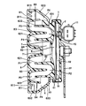
- FIG. 2 is a vertical sectional view of the electronic sounding device taken along line II-II in FIG. 1.
- Figure 1 shows the external appearance of an electronic horn.
- the horn main body includes a cylindrical metal casing 1 that opens in the front-rear direction (left-right direction in FIG. 1) in a state where it is installed in the vehicle.
- the “front-rear direction” does not indicate an absolute direction, and the direction in which the sound of the alarm sound is emitted depending on the installation state of the alarm sound main body is defined as the front.
- a resin-made intermediate body 6 that gradually increases in diameter is extended forward, and a cover body 8 is covered with the circular opening.
- a louver 81 is formed on the entire circumference of the front outermost peripheral portion of the cover body 8.
- Fig. 2 shows a vertical cross section of the horn along the line II-II in Fig. 1.
- a container-like resin holder 2 that is opened forward is held in the cylinder of the casing 1, and on the bottom wall of the holder 2, there is an alarm signal generation circuit, an amplifier circuit, or the like.
- a circuit board (not shown) provided with a configured alarm circuit is provided.
- An attachment stay 22 is bolted to the outer surface of the bottom wall of the holder 2.
- the opening of the holder 2 is closed and a vibrating body 51 made of a metal plate is stretched, and a circular piezoelectric body 52 is bonded to the center of the back surface of the vibrating body 51.
- An output line extends from the circuit board to each of the vibrating bodies 51 communicating with one electrode (not shown) of the piezoelectric body 52 and the other electrode (not shown) of the piezoelectric body 52.
- the alarm circuit on the circuit board is connected to a power supply connector 11 provided outside the casing 1.
- the power supply connector 11 is connected to a circuit board provided outside.
- the intermediate body 6 includes an inner cylinder body 62 and an outer cylinder body 63.
- the inner cylindrical body 62 is formed in a double container shape having cylindrical waterproof walls 621 and 622 that open forward.
- the outer peripheral edge of the bottom wall of the inner cylindrical body 62 is covered with the opening of the holder 2 while narrowing the outer peripheral edge of the vibrating body 51, and is fixed by caulking by the opening edge of the casing 1.
- the center portion of the bottom wall located in the waterproof wall 621 of the inner cylindrical body 62 is bent and protruded into the cylinder in a mountain shape, thereby forming a resonance space S between the vibrating body 51 and the resonator 7.
- a circular opening 71 is formed at the top in the center of the bottom wall constituting the resonator 7.
- the periphery of the inner cylinder 62 is surrounded by the outer cylinder 63.
- the outer cylinder 63 is formed in a relatively shallow container shape, and an opening 631 in the bottom wall is fitted on the outer periphery of the waterproof wall 622 of the inner cylinder 62.
- An outer peripheral cylindrical wall (waterproof wall) 633 of the outer cylindrical body 63 expands forward and outward, and the whole is a reflecting plate.
- a cover body 8 is provided to cover the front of the intermediate body 6.
- the cover body 8 has a circular shape with the same diameter as the opening of the outer cylindrical body 63, and a central portion 82 formed in a cylindrical shape whose one end is closed enters a substantially intermediate position in the waterproof wall 621 of the inner cylindrical body 62.
- a cylindrical waterproof wall 83 protruding rearward is formed on the outer peripheral portion of the cover body 8. The cylinder end of the waterproof wall 83 has advanced to a substantially intermediate position between the waterproof walls 621 and 622 of the inner cylinder 62, and the waterproof wall 83 is gradually thinner toward the cylinder end.
- louver 81 formed on the entire outermost periphery of the cover body 8, as shown in FIG. 2, a plurality of blades 811 inclined downward toward the rear are formed at equal intervals in the vertical direction.
- the opening formed in the installation part of the louver 81 is closed by the overlap of the upper and lower blades 811 of the louver 81 when viewed from the front straight direction.
- a drain port 632 is formed in the outer peripheral cylindrical wall 633 near the louver 81 at the lowest position of the alarm device body.
- a buffer chamber BR (see FIG. 5) having a predetermined capacity communicated with the resonator 7 through the opening 71 between the waterproof wall 621 of the inner cylinder 62 and the cover body 8 in the electronic sound alarm.
- a space defined by a single chain line) is formed.
- path P1 which reversely curves from the buffer chamber BR to the outer peripheral side back is formed by the center part 82 of the cover body 8 which entered the cylinder of the waterproof wall 621, and further the waterproof wall outside the cylinder of the waterproof wall 621
- a plurality of second passages P2, P3, and P4 are formed on the outer peripheral side following the first passage P1 by the waterproof wall 83 that has entered the cylinder 622.
- the innermost peripheral second passage P2 that communicates with the first passage P1 and reverses and curves forward on the outer peripheral side, and further, the inner peripheral second passage P3 that curves backward and reversely following the innermost peripheral second passage P2. Then, an outermost peripheral second passage P4 that curves further reversely forward is formed concentrically in the sound alarm centering on the opening 71 of the resonator 7 following the inner peripheral portion second passage P3.
- the alarm sound output from the resonator 7 is efficiently amplified forward with sufficient directivity while being resonantly amplified by the megaphone effect of the first passage P1 and the second passages P2 to P4 that gradually increase in diameter. Is output automatically. At this time, the alarm sound is sent forward through the gap between the blades 811 of the louver 81 without any problem.
- the first passage P1 and the second passages P2 to P4 that exert the megaphone effect are in series in the radial direction, the main body of the alarm device does not protrude greatly in the front-rear direction and becomes a compact shape.
- a plurality of second passages are provided, but only one second passage on the outermost periphery may be provided.
Landscapes
- Physics & Mathematics (AREA)
- Engineering & Computer Science (AREA)
- Acoustics & Sound (AREA)
- Multimedia (AREA)
- Piezo-Electric Transducers For Audible Bands (AREA)
- Emergency Alarm Devices (AREA)
- Transducers For Ultrasonic Waves (AREA)
- Burglar Alarm Systems (AREA)
- Details Of Audible-Bandwidth Transducers (AREA)
Priority Applications (4)
| Application Number | Priority Date | Filing Date | Title |
|---|---|---|---|
| US16/488,092 US11145286B2 (en) | 2017-03-01 | 2018-02-23 | Electronic horn |
| CN201880014927.7A CN110366750B (zh) | 2017-03-01 | 2018-02-23 | 电子式警音器 |
| DE112018000691.3T DE112018000691B4 (de) | 2017-03-01 | 2018-02-23 | Elektronisches Alarmhorn |
| CN202010293482.XA CN111508458B (zh) | 2017-03-01 | 2018-02-23 | 电子式警音器 |
Applications Claiming Priority (2)
| Application Number | Priority Date | Filing Date | Title |
|---|---|---|---|
| JP2017037879A JP6493929B2 (ja) | 2017-03-01 | 2017-03-01 | 電子式警音器 |
| JP2017-037879 | 2017-03-01 |
Publications (1)
| Publication Number | Publication Date |
|---|---|
| WO2018159490A1 true WO2018159490A1 (ja) | 2018-09-07 |
Family
ID=63371435
Family Applications (1)
| Application Number | Title | Priority Date | Filing Date |
|---|---|---|---|
| PCT/JP2018/006702 Ceased WO2018159490A1 (ja) | 2017-03-01 | 2018-02-23 | 電子式警音器 |
Country Status (5)
| Country | Link |
|---|---|
| US (1) | US11145286B2 (enExample) |
| JP (1) | JP6493929B2 (enExample) |
| CN (2) | CN111508458B (enExample) |
| DE (1) | DE112018000691B4 (enExample) |
| WO (1) | WO2018159490A1 (enExample) |
Cited By (1)
| Publication number | Priority date | Publication date | Assignee | Title |
|---|---|---|---|---|
| US11308930B2 (en) | 2017-11-09 | 2022-04-19 | Imasen Electric Industrial Co., Ltd. | Electronic horn |
Citations (4)
| Publication number | Priority date | Publication date | Assignee | Title |
|---|---|---|---|---|
| JPS5547007U (enExample) * | 1978-09-18 | 1980-03-27 | ||
| JPH0678998U (ja) * | 1993-04-19 | 1994-11-04 | アンデン株式会社 | 警報器 |
| JP2007316450A (ja) * | 2006-05-26 | 2007-12-06 | Raza V Ltd | 携帯用防犯ブザー |
| JP2012148657A (ja) * | 2011-01-18 | 2012-08-09 | Denso Corp | 車両接近通報装置 |
Family Cites Families (30)
| Publication number | Priority date | Publication date | Assignee | Title |
|---|---|---|---|---|
| US1904759A (en) * | 1931-05-25 | 1933-04-18 | Trico Products Corp | Fluid pressure horn |
| JPS5713490A (en) | 1980-06-27 | 1982-01-23 | Sharp Kk | Sound generator driving system |
| JPS58162994A (ja) | 1982-03-19 | 1983-09-27 | 株式会社デンソー | 電気式警音器 |
| JPH0610399Y2 (ja) | 1988-10-15 | 1994-03-16 | 太陽誘電株式会社 | 圧電ブザー |
| US5012221A (en) | 1989-03-24 | 1991-04-30 | Siren Sounds, Inc. | Emergency vehicle audible warning system and method |
| US4963855A (en) | 1990-02-21 | 1990-10-16 | Kobishi Electric Co., Inc. Ltd. | Warning sound generating device |
| JPH04119497U (ja) | 1991-04-09 | 1992-10-26 | 山口電機工業株式会社 | 防水用圧電ブザー |
| US5293149A (en) | 1991-04-12 | 1994-03-08 | Sparton Corporation | Vehicle horn with electronic solid state energizing circuit |
| JPH07222284A (ja) | 1994-02-02 | 1995-08-18 | Purimo:Kk | ホーン型圧電セラミックスピーカ |
| JPH08278368A (ja) * | 1995-04-03 | 1996-10-22 | Mazda Motor Corp | 障害物検知装置 |
| JP3328531B2 (ja) | 1997-01-16 | 2002-09-24 | 株式会社モルテン | 電子ホイッスル |
| GB2354903B (en) | 1997-02-22 | 2001-05-16 | Fulleon Ltd | Piezoelectric sounder |
| TW426300U (en) * | 1999-05-27 | 2001-03-11 | Shie Jen Ming | High decibel audio speaker structure with composite resonance gain audio |
| CA2488603A1 (en) | 2002-06-06 | 2004-01-22 | Fabbrica Italiana Accumulatori Motocarri Montecchio F.I.A.M.M. S.P.A. | Acoustic-signal emitting device for vehicles |
| US20070057778A1 (en) * | 2005-09-14 | 2007-03-15 | Floyd Bell, Inc. | Alarm combining audio signaling and switch functions |
| US20080180230A1 (en) | 2007-01-31 | 2008-07-31 | Daniel Eugene Zimmermann | Electronic horn having simulated start and end sounds |
| JP5276956B2 (ja) * | 2008-11-13 | 2013-08-28 | 浜名湖電装株式会社 | 電気式ホーン |
| CA2748252C (en) * | 2008-12-26 | 2014-05-27 | Panasonic Electric Works Co., Ltd. | Piezoelectric speaker, piezoelectric audio device employing piezoelectric speaker, and sensor with alert device attached |
| JP2012017036A (ja) * | 2010-07-08 | 2012-01-26 | Honda Motor Co Ltd | 車両用ホーンの取付構造 |
| JP5206762B2 (ja) | 2010-10-19 | 2013-06-12 | 株式会社デンソー | 車両用警報装置 |
| JP2012153303A (ja) * | 2011-01-27 | 2012-08-16 | Denso Corp | 車両接近通報装置 |
| JP5392335B2 (ja) | 2011-10-12 | 2014-01-22 | 株式会社デンソー | 車両存在通報装置 |
| JP2013097126A (ja) * | 2011-10-31 | 2013-05-20 | Denso Corp | 車両存在通報装置 |
| JP5713209B2 (ja) * | 2012-11-13 | 2015-05-07 | 丸子警報器株式会社 | 車両用ホーン |
| JP5949700B2 (ja) * | 2013-08-19 | 2016-07-13 | アンデン株式会社 | 圧電式ブザー |
| WO2015145659A1 (ja) | 2014-03-27 | 2015-10-01 | 衆智達技研株式会社 | 電子式警音器 |
| CN106232426B (zh) | 2014-05-01 | 2019-07-05 | 桑吉夫·帕特尔 | 电子非接触式喇叭和声音装置 |
| WO2015186239A1 (ja) | 2014-06-06 | 2015-12-10 | 衆智達技研株式会社 | 電子式警音器 |
| JP5916931B1 (ja) * | 2015-07-28 | 2016-05-11 | 衆智達技研株式会社 | 電子式警音器 |
| WO2019092828A1 (ja) | 2017-11-09 | 2019-05-16 | 株式会社今仙電機製作所 | 電子式警音器 |
-
2017
- 2017-03-01 JP JP2017037879A patent/JP6493929B2/ja active Active
-
2018
- 2018-02-23 US US16/488,092 patent/US11145286B2/en active Active
- 2018-02-23 WO PCT/JP2018/006702 patent/WO2018159490A1/ja not_active Ceased
- 2018-02-23 CN CN202010293482.XA patent/CN111508458B/zh active Active
- 2018-02-23 CN CN201880014927.7A patent/CN110366750B/zh active Active
- 2018-02-23 DE DE112018000691.3T patent/DE112018000691B4/de active Active
Patent Citations (4)
| Publication number | Priority date | Publication date | Assignee | Title |
|---|---|---|---|---|
| JPS5547007U (enExample) * | 1978-09-18 | 1980-03-27 | ||
| JPH0678998U (ja) * | 1993-04-19 | 1994-11-04 | アンデン株式会社 | 警報器 |
| JP2007316450A (ja) * | 2006-05-26 | 2007-12-06 | Raza V Ltd | 携帯用防犯ブザー |
| JP2012148657A (ja) * | 2011-01-18 | 2012-08-09 | Denso Corp | 車両接近通報装置 |
Cited By (1)
| Publication number | Priority date | Publication date | Assignee | Title |
|---|---|---|---|---|
| US11308930B2 (en) | 2017-11-09 | 2022-04-19 | Imasen Electric Industrial Co., Ltd. | Electronic horn |
Also Published As
| Publication number | Publication date |
|---|---|
| CN111508458B (zh) | 2024-02-20 |
| DE112018000691B4 (de) | 2023-06-22 |
| JP2018146601A (ja) | 2018-09-20 |
| US11145286B2 (en) | 2021-10-12 |
| CN110366750B (zh) | 2023-05-05 |
| CN110366750A (zh) | 2019-10-22 |
| CN111508458A (zh) | 2020-08-07 |
| DE112018000691T5 (de) | 2019-10-17 |
| JP6493929B2 (ja) | 2019-04-03 |
| US20200066243A1 (en) | 2020-02-27 |
Similar Documents
| Publication | Publication Date | Title |
|---|---|---|
| US6226927B1 (en) | Automobile vehicle door provided with a multicomponent module a part of which forms an acoustic cavity | |
| CN103003103B (zh) | 车辆围板和用于将超声波换能器集成到车辆围板中的方法 | |
| JP6251353B2 (ja) | 車両騒音を操作するために車両に搭載される音生成器 | |
| US7751582B2 (en) | Microphone with narrow directivity | |
| JP3999187B2 (ja) | 超音波センサの実装構造 | |
| US9963083B2 (en) | Vehicle loudspeaker system | |
| JP6493929B2 (ja) | 電子式警音器 | |
| JP4075733B2 (ja) | 超音波センサ | |
| JP2020179776A (ja) | 車両接近報知音発生装置 | |
| WO2019092828A1 (ja) | 電子式警音器 | |
| JP2012088414A (ja) | 車両用ホーン | |
| JP2007056841A (ja) | 吸気音制御構造体 | |
| JP6567462B2 (ja) | 電子式警音器 | |
| EP4221254A1 (en) | Loudspeaker arrangement | |
| JP6445171B2 (ja) | 移動体用スピーカシステム及び移動体 | |
| JP6378019B2 (ja) | 音検出装置 | |
| US1632331A (en) | Submarine sound receiver | |
| CN206542542U (zh) | 预防水膜形成的工程机械设备用报警装置的外壳 | |
| JPH0927995A (ja) | 電気機器のスピーカ防水構造 | |
| JP2018146601A5 (enExample) | ||
| JP2006237900A (ja) | スピーカー装置 | |
| CN223553453U (zh) | 一种高灵敏度扬声器 | |
| JP5068679B2 (ja) | スピーカ | |
| JP2004070019A (ja) | 防水型ホーン | |
| JP2002144972A (ja) | 車載用スピーカの構造 |
Legal Events
| Date | Code | Title | Description |
|---|---|---|---|
| 121 | Ep: the epo has been informed by wipo that ep was designated in this application |
Ref document number: 18760666 Country of ref document: EP Kind code of ref document: A1 |
|
| 122 | Ep: pct application non-entry in european phase |
Ref document number: 18760666 Country of ref document: EP Kind code of ref document: A1 |