WO2018159456A1 - 蓄電モジュール及び蓄電モジュールの製造方法 - Google Patents
蓄電モジュール及び蓄電モジュールの製造方法 Download PDFInfo
- Publication number
- WO2018159456A1 WO2018159456A1 PCT/JP2018/006508 JP2018006508W WO2018159456A1 WO 2018159456 A1 WO2018159456 A1 WO 2018159456A1 JP 2018006508 W JP2018006508 W JP 2018006508W WO 2018159456 A1 WO2018159456 A1 WO 2018159456A1
- Authority
- WO
- WIPO (PCT)
- Prior art keywords
- opening
- base member
- storage module
- power storage
- opening end
- Prior art date
- Legal status (The legal status is an assumption and is not a legal conclusion. Google has not performed a legal analysis and makes no representation as to the accuracy of the status listed.)
- Ceased
Links
Images


















Classifications
-
- H—ELECTRICITY
- H01—ELECTRIC ELEMENTS
- H01G—CAPACITORS; CAPACITORS, RECTIFIERS, DETECTORS, SWITCHING DEVICES, LIGHT-SENSITIVE OR TEMPERATURE-SENSITIVE DEVICES OF THE ELECTROLYTIC TYPE
- H01G11/00—Hybrid capacitors, i.e. capacitors having different positive and negative electrodes; Electric double-layer [EDL] capacitors; Processes for the manufacture thereof or of parts thereof
- H01G11/10—Multiple hybrid or EDL capacitors, e.g. arrays or modules
- H01G11/12—Stacked hybrid or EDL capacitors
-
- H—ELECTRICITY
- H01—ELECTRIC ELEMENTS
- H01G—CAPACITORS; CAPACITORS, RECTIFIERS, DETECTORS, SWITCHING DEVICES, LIGHT-SENSITIVE OR TEMPERATURE-SENSITIVE DEVICES OF THE ELECTROLYTIC TYPE
- H01G11/00—Hybrid capacitors, i.e. capacitors having different positive and negative electrodes; Electric double-layer [EDL] capacitors; Processes for the manufacture thereof or of parts thereof
- H01G11/14—Arrangements or processes for adjusting or protecting hybrid or EDL capacitors
- H01G11/18—Arrangements or processes for adjusting or protecting hybrid or EDL capacitors against thermal overloads, e.g. heating, cooling or ventilating
-
- H—ELECTRICITY
- H01—ELECTRIC ELEMENTS
- H01G—CAPACITORS; CAPACITORS, RECTIFIERS, DETECTORS, SWITCHING DEVICES, LIGHT-SENSITIVE OR TEMPERATURE-SENSITIVE DEVICES OF THE ELECTROLYTIC TYPE
- H01G11/00—Hybrid capacitors, i.e. capacitors having different positive and negative electrodes; Electric double-layer [EDL] capacitors; Processes for the manufacture thereof or of parts thereof
- H01G11/22—Electrodes
- H01G11/26—Electrodes characterised by their structure, e.g. multi-layered, porosity or surface features
- H01G11/28—Electrodes characterised by their structure, e.g. multi-layered, porosity or surface features arranged or disposed on a current collector; Layers or phases between electrodes and current collectors, e.g. adhesives
-
- H—ELECTRICITY
- H01—ELECTRIC ELEMENTS
- H01G—CAPACITORS; CAPACITORS, RECTIFIERS, DETECTORS, SWITCHING DEVICES, LIGHT-SENSITIVE OR TEMPERATURE-SENSITIVE DEVICES OF THE ELECTROLYTIC TYPE
- H01G11/00—Hybrid capacitors, i.e. capacitors having different positive and negative electrodes; Electric double-layer [EDL] capacitors; Processes for the manufacture thereof or of parts thereof
- H01G11/78—Cases; Housings; Encapsulations; Mountings
- H01G11/82—Fixing or assembling a capacitive element in a housing, e.g. mounting electrodes, current collectors or terminals in containers or encapsulations
-
- H—ELECTRICITY
- H01—ELECTRIC ELEMENTS
- H01M—PROCESSES OR MEANS, e.g. BATTERIES, FOR THE DIRECT CONVERSION OF CHEMICAL ENERGY INTO ELECTRICAL ENERGY
- H01M10/00—Secondary cells; Manufacture thereof
- H01M10/04—Construction or manufacture in general
- H01M10/0413—Large-sized flat cells or batteries for motive or stationary systems with plate-like electrodes
- H01M10/0418—Large-sized flat cells or batteries for motive or stationary systems with plate-like electrodes with bipolar electrodes
-
- H—ELECTRICITY
- H01—ELECTRIC ELEMENTS
- H01M—PROCESSES OR MEANS, e.g. BATTERIES, FOR THE DIRECT CONVERSION OF CHEMICAL ENERGY INTO ELECTRICAL ENERGY
- H01M10/00—Secondary cells; Manufacture thereof
- H01M10/04—Construction or manufacture in general
- H01M10/0481—Compression means other than compression means for stacks of electrodes and separators
-
- H—ELECTRICITY
- H01—ELECTRIC ELEMENTS
- H01M—PROCESSES OR MEANS, e.g. BATTERIES, FOR THE DIRECT CONVERSION OF CHEMICAL ENERGY INTO ELECTRICAL ENERGY
- H01M50/00—Constructional details or processes of manufacture of the non-active parts of electrochemical cells other than fuel cells, e.g. hybrid cells
- H01M50/10—Primary casings; Jackets or wrappings
- H01M50/183—Sealing members
- H01M50/184—Sealing members characterised by their shape or structure
-
- H—ELECTRICITY
- H01—ELECTRIC ELEMENTS
- H01M—PROCESSES OR MEANS, e.g. BATTERIES, FOR THE DIRECT CONVERSION OF CHEMICAL ENERGY INTO ELECTRICAL ENERGY
- H01M50/00—Constructional details or processes of manufacture of the non-active parts of electrochemical cells other than fuel cells, e.g. hybrid cells
- H01M50/10—Primary casings; Jackets or wrappings
- H01M50/183—Sealing members
- H01M50/186—Sealing members characterised by the disposition of the sealing members
-
- H—ELECTRICITY
- H01—ELECTRIC ELEMENTS
- H01M—PROCESSES OR MEANS, e.g. BATTERIES, FOR THE DIRECT CONVERSION OF CHEMICAL ENERGY INTO ELECTRICAL ENERGY
- H01M50/00—Constructional details or processes of manufacture of the non-active parts of electrochemical cells other than fuel cells, e.g. hybrid cells
- H01M50/30—Arrangements for facilitating escape of gases
- H01M50/317—Re-sealable arrangements
- H01M50/325—Re-sealable arrangements comprising deformable valve members, e.g. elastic or flexible valve members
-
- H—ELECTRICITY
- H01—ELECTRIC ELEMENTS
- H01G—CAPACITORS; CAPACITORS, RECTIFIERS, DETECTORS, SWITCHING DEVICES, LIGHT-SENSITIVE OR TEMPERATURE-SENSITIVE DEVICES OF THE ELECTROLYTIC TYPE
- H01G11/00—Hybrid capacitors, i.e. capacitors having different positive and negative electrodes; Electric double-layer [EDL] capacitors; Processes for the manufacture thereof or of parts thereof
- H01G11/78—Cases; Housings; Encapsulations; Mountings
-
- H—ELECTRICITY
- H01—ELECTRIC ELEMENTS
- H01G—CAPACITORS; CAPACITORS, RECTIFIERS, DETECTORS, SWITCHING DEVICES, LIGHT-SENSITIVE OR TEMPERATURE-SENSITIVE DEVICES OF THE ELECTROLYTIC TYPE
- H01G11/00—Hybrid capacitors, i.e. capacitors having different positive and negative electrodes; Electric double-layer [EDL] capacitors; Processes for the manufacture thereof or of parts thereof
- H01G11/84—Processes for the manufacture of hybrid or EDL capacitors, or components thereof
-
- H—ELECTRICITY
- H01—ELECTRIC ELEMENTS
- H01M—PROCESSES OR MEANS, e.g. BATTERIES, FOR THE DIRECT CONVERSION OF CHEMICAL ENERGY INTO ELECTRICAL ENERGY
- H01M2220/00—Batteries for particular applications
- H01M2220/20—Batteries in motive systems, e.g. vehicle, ship, plane
-
- Y—GENERAL TAGGING OF NEW TECHNOLOGICAL DEVELOPMENTS; GENERAL TAGGING OF CROSS-SECTIONAL TECHNOLOGIES SPANNING OVER SEVERAL SECTIONS OF THE IPC; TECHNICAL SUBJECTS COVERED BY FORMER USPC CROSS-REFERENCE ART COLLECTIONS [XRACs] AND DIGESTS
- Y02—TECHNOLOGIES OR APPLICATIONS FOR MITIGATION OR ADAPTATION AGAINST CLIMATE CHANGE
- Y02E—REDUCTION OF GREENHOUSE GAS [GHG] EMISSIONS, RELATED TO ENERGY GENERATION, TRANSMISSION OR DISTRIBUTION
- Y02E60/00—Enabling technologies; Technologies with a potential or indirect contribution to GHG emissions mitigation
- Y02E60/10—Energy storage using batteries
-
- Y—GENERAL TAGGING OF NEW TECHNOLOGICAL DEVELOPMENTS; GENERAL TAGGING OF CROSS-SECTIONAL TECHNOLOGIES SPANNING OVER SEVERAL SECTIONS OF THE IPC; TECHNICAL SUBJECTS COVERED BY FORMER USPC CROSS-REFERENCE ART COLLECTIONS [XRACs] AND DIGESTS
- Y02—TECHNOLOGIES OR APPLICATIONS FOR MITIGATION OR ADAPTATION AGAINST CLIMATE CHANGE
- Y02P—CLIMATE CHANGE MITIGATION TECHNOLOGIES IN THE PRODUCTION OR PROCESSING OF GOODS
- Y02P70/00—Climate change mitigation technologies in the production process for final industrial or consumer products
- Y02P70/50—Manufacturing or production processes characterised by the final manufactured product
-
- Y—GENERAL TAGGING OF NEW TECHNOLOGICAL DEVELOPMENTS; GENERAL TAGGING OF CROSS-SECTIONAL TECHNOLOGIES SPANNING OVER SEVERAL SECTIONS OF THE IPC; TECHNICAL SUBJECTS COVERED BY FORMER USPC CROSS-REFERENCE ART COLLECTIONS [XRACs] AND DIGESTS
- Y02—TECHNOLOGIES OR APPLICATIONS FOR MITIGATION OR ADAPTATION AGAINST CLIMATE CHANGE
- Y02T—CLIMATE CHANGE MITIGATION TECHNOLOGIES RELATED TO TRANSPORTATION
- Y02T10/00—Road transport of goods or passengers
- Y02T10/60—Other road transportation technologies with climate change mitigation effect
- Y02T10/70—Energy storage systems for electromobility, e.g. batteries
Definitions
- One aspect of the present invention relates to a power storage module and a method for manufacturing the power storage module.
- a bipolar battery (storage module) that includes a bipolar electrode in which a positive electrode is formed on one surface of a current collector and a negative electrode is formed on the other surface (see Patent Document 1).
- an electrolytic solution is sealed in an internal space defined by a separator, a current collector, and a seal member.
- Bipolar electrodes are laminated via an electrolyte layer made of a separator impregnated with an electrolytic solution.
- the battery is provided with a tube that penetrates the seal portion. One end of the tube faces the internal space, and the other end faces the external space of the battery. When the internal space pressure increases while using the battery, this tube functions as a pressure regulating valve.
- a configuration of the bipolar battery for example, a configuration in which an opening communicating with the internal space between the bipolar electrodes is provided on the side surface of the laminated body of the bipolar electrodes can be considered.
- the opening functions as a liquid injection port into which the electrolytic solution is injected, and also functions as a connection port of a pressure adjusting valve for adjusting the pressure in the internal space.
- a mechanism capable of appropriately and easily injecting the electrolyte into each internal space is required.
- it is preferable to confirm in advance that the valve opening pressure is a predetermined set value. However, it is often after the pressure regulating valve is assembled to the bipolar battery that the pressure regulating valve is able to perform its function. For this reason, it may be difficult to inspect the pressure regulating valve in advance.
- the valve opening pressure is preferably set to a predetermined value.
- the pressure regulating valve includes a base member provided with a communication hole communicating with the internal space, an elastic member disposed so as to close the open end of the communication hole, and a pressing member that presses the elastic member against the base member. May have.
- the valve opening pressure can be determined by adjusting the design dimensions of the base member, the elastic member, and the pressing member so that the compressibility of the elastic member in the pressing direction becomes a predetermined value.
- the valve opening pressure of the pressure regulating valve may not be a desired value due to a dimensional tolerance of each member.
- An object of the present invention is to improve the functionality of a power storage module including a pressure regulating valve as described above.
- the first aspect of the present invention is to provide a power storage module and a method for manufacturing the power storage module that can easily inspect the pressure control valve before the assembly of the pressure control valve.
- a second aspect of the present invention provides a power storage module and a method for manufacturing a power storage module that can improve the workability of electrolyte injection and can easily inspect the pressure control valve before the pressure control valve is assembled. The purpose is to provide.
- the third aspect of the present invention aims to provide a power storage module capable of stabilizing the internal pressure.
- the fourth aspect of the present invention is to provide a power storage module capable of appropriately adjusting the pressure in each internal space by one pressure adjusting valve common to a plurality of internal spaces.
- the fifth aspect of the present invention aims to provide a power storage module capable of adjusting the valve opening pressure of the pressure regulating valve to a desired value and a method for manufacturing the power storage module.
- An electricity storage module is provided on an electrode plate having a first surface and a second surface opposite to the first surface, a positive electrode provided on the first surface, and a second surface.
- a pressure regulating valve connected to the opening, the pressure regulating valve having a plurality of communication holes communicating with each of the plurality of internal spaces through the opening, and a base member connected to the opening;
- An elastic member disposed so as to close the second opening end located on the side opposite to the first opening end on the opening side of the plurality of communication holes, and a pressing member that presses the elastic member against the base member.
- the pressure regulating valve has a base member provided with a plurality of communication holes, an elastic member, and a pressing member, so that the pressure regulating valve is connected to the opening of the frame body before the pressure regulating valve is connected.
- An inspection can be performed. For example, by sending air from the first opening end of each communication hole of the base member into the communication hole, the pressure value when the second opening end of the communication hole by the elastic member is released can be confirmed. . Therefore, according to the power storage module, the pressure regulating valve can be easily inspected before the pressure regulating valve is assembled.
- the power storage module includes a plurality of pressure regulating valves, and the frame body is provided with a plurality of openings to which the pressure regulating valves are respectively connected, and each of the plurality of openings has a different internal space for each opening. You may communicate.
- the number of internal spaces communicated with one opening that is, an internal pressure that needs to be adjusted with one pressure adjusting valve
- the cross-sectional area per one communicating hole of a pressure regulation valve can be enlarged, and the distribution
- the width in the stacking direction of the bipolar electrode at the first opening end may be equal to or greater than the product of the width in the stacking direction of one internal space and one electrode plate and the number of openings.
- a configuration in which a plurality of openings are provided in the frame body and a set of internal spaces communicating with each opening is made different, a configuration in which the internal space to be communicated with each opening is shifted by one stage for each opening is conceivable.
- the same pressure regulating valve can be used for any opening. Thereby, the number of parts can be reduced. Further, since it is not necessary to prepare a pressure regulating valve having a different structure for each opening, it is possible to prevent erroneous assembly such as connecting a pressure regulating valve of a standard that does not conform to the opening.
- the plurality of first opening ends may be arranged point-symmetrically with respect to an axis passing through the center of the first side surface facing the opening of the base member and orthogonal to the first side surface.
- the arrangement of the plurality of first opening ends with respect to the opening is the same in any of the two states (postures) of the pressure regulating valve that are in an inverted relationship with respect to the shaft.
- the pressure regulating valve can be normally connected to the opening.
- the pressure regulating valve can be easily connected to the opening.
- a plurality of grooves corresponding to each of the plurality of second opening ends are provided on the second side surface of the base member facing the elastic member, and correspond to the second opening end of the communication hole and the second opening end.
- the groove portion may be disposed so as to communicate with each other by separating a part of the elastic member from the second side surface in accordance with an increase in pressure in the internal space communicating with the communication hole. According to this configuration, as the pressure in the internal space increases, the gas in the internal space is transferred from the second opening end of the communication hole to the groove portion through the communication hole of the base member that communicates with the internal space. Can be discharged. Thereby, the pressure in internal space can be adjusted appropriately.
- the distance between the second opening end and the groove corresponding to the second opening end may be shorter than the distance between the second opening end and another second opening end adjacent to the second opening end.
- the base member is connected to a plurality of groove portions to define a circulation space for circulating the gas released from the internal space.
- the base member has an exhaust port for communicating the circulation space and the outside of the base member. It may be provided. According to this configuration, the gas discharged to the one groove portion in response to the increase in the pressure in the internal space flows into the circulation space provided in common to the plurality of groove portions, and is discharged to the outside from the exhaust port. Therefore, the gas generated in the internal space can be appropriately discharged to the outside with a simple configuration.
- the frame body includes a first seal portion that holds an edge portion of the electrode plate, and a second seal portion that is provided around the first seal portion when viewed from the stacking direction of the bipolar electrode.
- a plurality of first openings provided in one seal portion and communicating with different internal spaces; and a second opening provided in the second seal portion and communicating with the plurality of first openings.
- the plurality of communication holes communicate with different internal spaces through the plurality of first openings, the first opening has a rectangular shape, and the first opening end Is formed in a size including the first opening when viewed from the connecting direction of the opening and the pressure regulating valve, and the second opening end may be circular.
- the method for manufacturing an electricity storage module according to the first aspect of the present invention includes an electrode plate having a first surface and a second surface opposite to the first surface, a positive electrode provided on the first surface, and a second surface. And a negative electrode provided on each of the plurality of bipolar electrodes.
- a base member connected to the elastic member, an elastic member disposed so as to close the second opening end located on the opposite side of the first opening end on the opening side of the plurality of communication holes, and the elastic member with respect to the base member
- a pressure regulating valve having a pressing member for pressing
- the pressure regulating valve includes a base member provided with a plurality of communication holes, an elastic member, and a pressing member, so that the pressure regulating valve is connected to the opening of the frame body before the pressure regulating valve is connected. An inspection can be performed. Therefore, according to the manufacturing method, the pressure regulating valve can be easily inspected before the pressure regulating valve is assembled.
- An electricity storage module is provided on an electrode plate having a first surface and a second surface opposite to the first surface, a positive electrode provided on the first surface, and a second surface.
- a pressure regulating valve connected to the opening, wherein the pressure regulating valve is provided with a plurality of first communication holes that communicate with each of the plurality of internal spaces through the opening, and is connected to the opening.
- a plurality of second communication holes that communicate with one base member and each of the plurality of first communication holes, and a plurality of second base members that are joined to a side surface opposite to the opening side of the first base member; An opening end located on the side opposite to the opening end of the second communication hole on the first base member side Having an elastic member disposed Guyo, a pressing member for pressing the elastic member with respect to the second base member.
- this power storage module it is possible to inject an electrolytic solution into each internal space using the first base member provided with a plurality of first communication holes communicating with each of the plurality of internal spaces. Yes. Specifically, at the time of manufacturing the power storage module, before joining the first base member to the second base member, by connecting the first base member to the opening of the frame body, It is possible to inject electrolyte into each internal space. Moreover, it is also possible to perform an inspection of the pressure regulating valve using the second base member provided with a plurality of second communication holes. Specifically, it is possible to perform an inspection on a unit (pressure regulating valve submodule) including the second base member, the elastic member, and the pressing member.
- a unit pressure regulating valve submodule
- the power storage module includes a plurality of pressure regulating valves, and the frame body is provided with a plurality of openings to which the pressure regulating valves are respectively connected, and each of the plurality of openings has a different internal space for each opening. You may communicate.
- the number of internal spaces communicated with one opening that is, an internal pressure that needs to be adjusted with one pressure adjusting valve
- the cross-sectional area per one communicating hole of a pressure regulation valve can be enlarged, and the distribution
- the width in the stacking direction of the bipolar electrode at the opening end on the opening side of the first communication hole may be greater than or equal to the product of the width in the stacking direction of one internal space and one electrode plate and the number of openings.
- a configuration in which a plurality of openings are provided in the frame body and a set of internal spaces communicating with each opening is made different, a configuration in which the internal space to be communicated with each opening is shifted by one stage for each opening is conceivable.
- the same pressure regulating valve is used for any opening by setting the width in the stacking direction of the opening end on the opening (frame opening) side of the first communication hole as described above. It becomes possible. Thereby, the number of parts can be reduced. Further, since it is not necessary to prepare a pressure regulating valve having a different structure for each opening, it is possible to prevent erroneous assembly such as connecting a pressure regulating valve of a standard that does not conform to the opening.
- the opening ends on the opening side of the plurality of first communication holes may be arranged point-symmetrically with respect to an axis that passes through the center of the first side surface facing the opening of the first base member and is orthogonal to the first side surface.
- the opening ends on the second base member side of the plurality of first communication holes and the opening ends on the first base member side of the plurality of second communication holes may be arranged point-symmetrically with respect to the axis.
- the second base member of the plurality of first communication holes in any of the two states (postures) of the first base member (or the second base member) that are in an inverted relationship with respect to the shaft.
- the arrangement of the opening ends on the first base member side of the plurality of second communication holes with respect to the opening ends on the side is the same. For this reason, it becomes possible to normally join the second base member to the first base member in either of the two states. As a result, the second base member can be easily joined to the first base member. In addition, it is possible to prevent erroneous assembly such as joining the second base member in the wrong direction with respect to the first base member.
- the second side surface of the second base member facing the elastic member is provided with a plurality of groove portions corresponding to the respective open ends of the plurality of second communication holes on the elastic member side, and the open end and the open end May be arranged so that a part of the elastic member is separated from the second side surface and communicates with each other in accordance with an increase in pressure in the internal space communicating with the second communication hole.
- the gas in the internal space is caused to flow from the opening end on the elastic member side of the second communication hole via the second communication hole communicating with the internal space. It can be discharged into the groove. Thereby, the pressure in internal space can be adjusted appropriately.
- the distance between the opening end of the second communication hole on the elastic member side and the groove corresponding to the opening end may be shorter than the distance between the opening end and another opening end adjacent to the opening end.
- the second base member is connected to a plurality of grooves and defines a circulation space for circulating the gas released from the internal space.
- the second base member includes a circulation space and an outside of the second base member. There may be provided an exhaust port for communicating. According to this configuration, the gas discharged to the one groove portion in response to the increase in the pressure in the internal space flows into the circulation space provided in common to the plurality of groove portions, and is discharged to the outside from the exhaust port. Therefore, the gas generated in the internal space can be appropriately discharged to the outside with a simple configuration.
- At least a portion on the second base member side of the first communication hole is formed in a tapered shape having a cross-sectional area that increases from the opening side toward the second base member side, and the second communication hole is formed on the first base member side. It may be formed in a taper shape in which the cross-sectional area becomes smaller toward the elastic member side.
- the first communication hole and the second communication hole can be formed by injection molding or the like.
- pressure loss can be suppressed, and communication holes (the first communication hole and the first communication hole) can be suppressed.
- the gas in the two communication holes) can be smoothly distributed.
- the opening area of the opening end on the elastic member side of the second communication hole may be larger than the opening area of the opening end on the opening side of the tapered portion of the first communication hole. According to this configuration, since the cross-sectional area on the outlet side of the flow path from the internal space toward the elastic member side is larger than the cross-sectional area on the inlet side, pressure loss can be more effectively suppressed.
- At least a portion on the second base member side of the first communication hole is formed in a tapered shape having a cross-sectional area that increases from the opening side toward the second base member side, and the second communication hole is formed on the first base member side. It may be formed in a taper shape in which the cross-sectional area becomes larger toward the elastic member side.
- the first communication hole and the second communication hole can be formed by injection molding or the like. Further, the pressure loss can be more effectively suppressed by providing the cross-sectional area of the flow path from the internal space toward the elastic member side so as to increase from the inlet side toward the outlet side.
- the width in the stacking direction of the bipolar electrode at the opening end on the second base member side of the first communication hole may be larger than the width in the stacking direction of the opening end on the opening side of the first communication hole. According to this configuration, it is possible to appropriately ensure the opening width of the joint portion between the first communication hole and the second communication hole. Thereby, for example, when the first base member and the second base member are joined by heat (for example, hot plate welding), it is possible to suppress the opening of the joint portion from being blocked.
- the frame body includes a first seal portion that holds an edge portion of the electrode plate, and a second seal portion that is provided around the first seal portion when viewed from the stacking direction of the bipolar electrode.
- a first base member having a plurality of first openings provided in one seal portion and communicating with different internal spaces; and a second opening provided in the second seal portion and communicating with the plurality of first openings.
- the plurality of first communication holes communicate with different internal spaces through the plurality of first openings, and the first opening is rectangular.
- the opening end on the opening side of the first communication hole is formed in a size including the first opening when viewed from the connecting direction of the opening and the pressure regulating valve, and the opening end on the elastic member side of the second communication hole. May be circular.
- the method for manufacturing a power storage module according to the second aspect of the present invention includes an electrode plate having a first surface and a second surface opposite to the first surface, a positive electrode provided on the first surface, and a second surface. And a negative electrode provided on each of the plurality of bipolar electrodes.
- a plurality of second communication holes for communicating with each other are provided.
- the second base member an elastic member disposed so as to close the opening end located on the opposite side of the plurality of second communication holes connected to the first communication hole, and the elastic member as the second base member
- a pressure regulating valve sub-module having a pressing member that presses against each other, and air is introduced into each second communication hole from an opening end on a side connected to the first communication hole of each second communication hole
- the electrolytic solution in the step of injecting the electrolytic solution, using the first base member provided with a plurality of first communication holes communicating with each of the plurality of internal spaces, the electrolytic solution is injected into each internal space. It is possible to do. Further, in the step of inspecting, it is possible to inspect the function as the pressure adjustment valve by executing an inspection on the pressure adjustment valve submodule which is a unit composed of the second base member, the elastic member, and the pressing member. ing. Therefore, according to the said manufacturing method, while improving the workability
- a plurality of bipolar electrodes each including an electrode plate, a positive electrode provided on the first surface of the electrode plate, and a negative electrode provided on the second surface of the electrode plate include separators.
- a plurality of bipolar electrodes extending in the stacking direction of the plurality of bipolar electrodes, each having a cylindrical seal portion that accommodates the plurality of bipolar electrodes, and being internally disposed between the plurality of bipolar electrodes and the seal portion.
- a space is formed, and the seal portion includes a cylindrical first seal portion joined to the peripheral portion of the electrode plate, and a cylindrical first seal portion provided outside the first seal portion in a direction intersecting the stacking direction.
- the first seal portion has a structure in which frames joined to the peripheral portion of the electrode plate are laminated in the laminating direction, and the frame is another 2 adjacent to the laminating direction.
- First end face and second end respectively contacting the two frame bodies
- a groove formed on at least one side of the first end surface and the second end surface and extending in a direction crossing the laminating direction and penetrating the inside and outside of the frame body, and the second seal portion is formed in the groove portion of the frame body Including an opening provided in a corresponding position, and the opening of the second seal portion is provided with a pressure adjusting valve configured to be connected to the internal space through the groove and adjust the pressure of the internal space.
- the frame joined to the peripheral edge of the electrode plate is laminated in the laminating direction to form the first seal portion.
- a groove is formed on at least one side of the first end surface and the second end surface of the frame. The groove extends in a direction intersecting the stacking direction and penetrates the inside and outside of the frame. Since the frames are in contact with each other at the first end surface and the second end surface in the stacking direction, the cross-sectional area of the groove portion as the communication channel is ensured. Therefore, the internal space pressure, that is, the internal pressure can be easily released to the outside of the frame through the groove. At this time, the internal pressure is adjusted by operating the pressure regulating valve.
- the separator is provided such that the outer peripheral end of the separator is positioned outside the inner peripheral end of the first seal portion, and the frame has a thickness larger than the thickness of the separator in the stacking direction.
- a step portion for arranging the outer peripheral end of the separator is formed on at least one side of the first end surface and the second end surface, and the depth of the groove portion in the stacking direction is larger than the depth of the step portion in the stacking direction. May be. In this case, the depth of the groove is increased, and the pressure loss in the groove can be further reduced.
- One or more protrusions may be provided on the bottom of the groove. In this case, deformation of the groove is prevented, and a cross-sectional area of the groove as the communication channel is ensured.
- the groove may be rectangular and the aspect ratio of the groove may be 5 or more.
- a groove as a communication channel can be suitably formed for a bipolar electrode (cell) having a limited thickness.
- An electricity storage module is provided on an electrode plate having a first surface and a second surface opposite to the first surface, a positive electrode provided on the first surface, and a second surface.
- a pressure regulating valve connected to the opening, the pressure regulating valve having a plurality of communication holes communicating with each of the plurality of internal spaces through the opening, and a base member connected to the opening;
- a plate-like elastic member disposed so as to close the second opening end located on the opposite side to the first opening end on the opening side of the plurality of communication holes, and the side opposite to the base member of the elastic member
- a pressing member that presses the elastic member against the base member from the side;
- Member has a positioning portion for positioning the elastic member relative to the pressing member.
- one end (first opening end) of the plurality of communication holes provided in the base member is communicated with each internal space of the bipolar electrode laminate through the opening of the frame body,
- the other end (second opening end) is closed by an elastic member pressed by the pressing member.
- pressure adjustment (exhaust) of the internal space can be performed for each internal space.
- the elastic member is positioned by a positioning portion provided on the pressing member side. Thereby, the structure by which the part by the side of the base member of an elastic member does not interfere with a positioning part is realizable. As a result, the pressure at which the elastic member presses the base member is less likely to vary for each position of the elastic member.
- variation for every 2nd opening end is reduced about the pressure at the time of gas being discharged
- the side surface of the base member on the elastic member side is provided with a plurality of grooves corresponding to each of the plurality of second opening ends, and the second opening end of the communication hole and the groove corresponding to the second opening end are
- the elastic members may be arranged so as to communicate with each other by separating from the side surface in accordance with an increase in pressure in the internal space communicating with the communication hole. According to this configuration, as the pressure in the internal space increases, the gas in the internal space is transferred from the second opening end of the communication hole to the groove portion through the communication hole of the base member that communicates with the internal space. Can be discharged. Thereby, the pressure in internal space can be adjusted appropriately.
- the distance between the second opening end and the groove corresponding to the second opening end may be shorter than the distance between the second opening end and another second opening end adjacent to the second opening end.
- the base member is connected to a plurality of groove portions to define a circulation space for circulating the gas released from the internal space.
- the base member has an exhaust port for communicating the circulation space and the outside of the base member. It may be provided. According to this configuration, the gas discharged to the one groove portion in response to the increase in the pressure in the internal space flows into the circulation space provided in common to the plurality of groove portions, and is discharged to the outside from the exhaust port. Therefore, the gas generated in the internal space can be appropriately discharged to the outside with a simple configuration.
- the positioning portion may be a concave groove into which the elastic member is fitted.
- an elastic member can be positioned by the simple structure which provides a groove part in a press member.
- the side surface of the base member and the surface of the pressing member that face each other across the elastic member may be parallel to each other. According to this configuration, since any part of the valve body can be pressed against the base member with a substantially equal force in a direction perpendicular to the side surface of the base member, the valve opening pressure for each internal space can be reduced. Variation can be effectively reduced.
- An electricity storage module is provided on an electrode plate having a first surface and a second surface opposite to the first surface, a positive electrode provided on the first surface, and a second surface.
- a pressure regulating valve connected to the opening, the pressure regulating valve having a plurality of communication holes communicating with each of the plurality of internal spaces through the opening, and a base member connected to the opening;
- An elastic member disposed so as to close the second opening end located on the side opposite to the first opening end on the opening side of the plurality of communication holes, and a pressing member that presses the elastic member against the base member.
- a base member as seen from a direction orthogonal to the pressing direction of the pressing member In a region where the member overlap each other, the base member and the pressing
- the base member and the pressing member are fixed to each other in the region. Therefore, the base member and the pressing member can be fixed after the pressing member is moved relative to the base member to a desired position in the pressing direction.
- the compression ratio of the elastic member in the pressing direction can be adjusted. Since the valve opening pressure is determined by the compression rate, according to the power storage module, the valve opening pressure of the pressure regulating valve can be adjusted to a desired value.
- a member located on the inner side of the pressing member and the base member in the region as viewed from the direction orthogonal to the pressing direction of the pressing member is smaller than the first transmittance with respect to the wavelength. It may have transmittance.
- the laser passes through the member positioned outside and reaches the member positioned inside.
- the pressing member and the base member can be firmly fixed to each other by laser welding.
- the method for manufacturing an electricity storage module includes an electrode plate having a first surface and a second surface opposite to the first surface, a positive electrode provided on the first surface, and a second surface. And a negative electrode provided on each of the plurality of bipolar electrodes.
- a pressure regulating valve having a pressing member for pressing Including a step of preparing and a step of connecting the pressure regulating valve to the opening, and the step of preparing the pressure regulating valve includes a step of pressing the elastic member against the base member by the pressing member, and a pressing direction of the pressing member.
- the base member and the pressing member can be fixed after moving the pressing member relative to the base member to a desired position in the pressing direction.
- the compression ratio of the elastic member in the pressing direction can be adjusted. Since the valve opening pressure is determined by the compression rate, according to the manufacturing method, the valve opening pressure of the pressure regulating valve can be adjusted to a desired value.
- the pressing member and the base member may be fixed to each other in a state in which the elastic member is pressed so that a value based on a load for pressing the elastic member by the pressing member becomes a predetermined value.
- the value based on the load changes according to the compression rate of the elastic member in the pressing direction, but does not depend on the dimensional tolerances of the pressing member, the elastic member, the base member, and the like. Therefore, the valve opening pressure of the pressure regulating valve can be adjusted to a desired value regardless of dimensional tolerances of the pressing member, the elastic member, the base member, and the like.
- the pressing member and the base member may be fixed to each other while the elastic member is pressed so that the dimension of the pressure regulating valve in the pressing direction becomes a predetermined value.
- the compression ratio of the elastic member in the pressing direction can be calculated from the difference between the reference value and the dimension of the pressure adjusting valve after pressing, using the dimension of the pressure adjusting valve in the pressing direction measured before pressing as a reference value. . Therefore, the influence of dimensional tolerances such as the pressing member, the elastic member, and the base member is offset. Therefore, the valve opening pressure of the pressure regulating valve can be adjusted to a desired value regardless of dimensional tolerances of the pressing member, the elastic member, the base member, and the like.
- the pressing member and the base member may be welded together by irradiating the region with a laser.
- the pressing member and the base member can be firmly fixed to each other by laser welding.
- the functionality of the power storage module including the pressure regulating valve can be improved.
- a power storage module and a method for manufacturing the power storage module that can improve the workability of the electrolyte injection and can easily inspect the pressure control valve before the pressure control valve is assembled. Can be done.
- the internal pressure can be stabilized by the cooperation of the groove and the pressure regulating valve.
- a power storage module capable of appropriately adjusting the pressure in each internal space with one pressure adjusting valve common to the plurality of internal spaces.
- a power storage module capable of adjusting the valve opening pressure of the pressure regulating valve to a desired value, and a method for manufacturing the power storage module can be provided.
- FIG. 6 is a schematic cross-sectional view showing an embodiment of a power storage device including the power storage modules of the first to fifth embodiments.
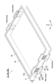
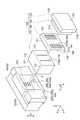
- FIG. It is a schematic sectional drawing which shows the electrical storage module of 1st, 2nd, 4th and 5th embodiment. It is a schematic perspective view which shows the electrical storage module (except a pressure regulation valve) of 1st, 2nd and 5th embodiment.
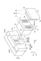
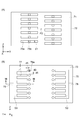
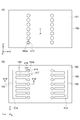
- FIG. 4 is an enlarged plan view of a part of the power storage module of FIG. 3. It is a disassembled perspective view of the pressure regulation valve connected to opening of a frame. It is a schematic sectional drawing which shows the structure of a pressure regulating valve. It is a top view which shows the (A) frame body opening side surface and (B) valve body side surface of a base member.
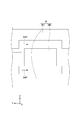
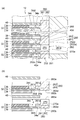
- FIG. 8 is a cross-sectional view taken along line VIII-VIII in FIG. 7, (A) is a view showing a valve closing state, and (B) is a view showing a valve opening state.
- It is a schematic sectional drawing which shows the frame formation process in the manufacturing method of an electrical storage module. It is a disassembled perspective view of the pressure control valve connected to opening of the frame of the electrical storage module of 2nd Embodiment. It is a schematic sectional drawing which shows the structure of a pressure regulating valve. It is a top view which shows the side surface by the side of the (A) frame body opening side of a 1st base member, and the (B) 2nd base member side.
- FIG. 14 is a cross-sectional view taken along line XIV-XIV in FIG. 13, (A) is a view showing a valve closing state, and (B) is a view showing a valve opening state.
- (A) is a figure for demonstrating the electrolyte solution injection
- (B) is for demonstrating the inspection process in the manufacturing method of the electrical storage module of 2nd Embodiment.
- FIG. It is a schematic sectional drawing which shows the electrical storage module of 3rd Embodiment.
- FIG. 18 is a cross-sectional view taken along line XIX-XIX in FIG.
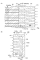
- A) is sectional drawing which shows the periphery structure of a resin part
- (b) is sectional drawing which shows the state before a bipolar battery is laminated
- A) is sectional drawing which shows a groove part
- (b) is sectional drawing which shows the modification of a groove part.
- FIG. 27 is a cross-sectional view taken along line XXVIII-XXVIII in FIG. 26, (A) is a view showing a valve closing state, and (B) is a view showing a valve opening state.
- (A) is a top view which shows the side surface by the side of the valve body of the base member of the electrical storage module which concerns on a comparative example
- (B) is sectional drawing along the bb line of (A). It is a figure which shows the seal surface pressure (simulation value) / target seal surface pressure for every opening position of this embodiment and a comparative example.
- (A) is a figure which shows the modification of a positioning part
- (B) is sectional drawing along the bb line of (A).
- (A) is a figure which shows a valve closing state
- (B) is a figure which shows a valve opening state.
- FIG. 1 is a schematic cross-sectional view illustrating an embodiment of a power storage device including a power storage module.
- FIG. 1 is a diagram showing a configuration common to power storage devices 10, 10A, 10B, 10C, and 10D according to the first to fifth embodiments.
- the power storage device 10 shown in the figure is used as a battery for various vehicles such as forklifts, hybrid vehicles, and electric vehicles.
- the power storage device 10 includes a plurality (three in the present embodiment) of power storage modules 12, but may include a single power storage module 12.
- the power storage module 12 is, for example, a bipolar battery.
- the power storage module 12 is a secondary battery such as a nickel hydride secondary battery or a lithium ion secondary battery, but may be an electric double layer capacitor. In the following description, a nickel metal hydride secondary battery is illustrated.
- the plurality of power storage modules 12 can be stacked via a conductive plate 14 such as a metal plate, for example. As viewed from the stacking direction D1, the power storage module 12 and the conductive plate 14 have, for example, a rectangular shape. Details of each power storage module 12 will be described later.
- the conductive plates 14 are also arranged outside the power storage modules 12 positioned at both ends in the stacking direction D1 (Z direction) of the power storage modules 12, respectively.
- the conductive plate 14 is electrically connected to the adjacent power storage module 12. Thereby, the some electrical storage module 12 is connected in series in the lamination direction D1.
- a positive electrode terminal 24 is connected to the conductive plate 14 located at one end, and a negative electrode terminal 26 is connected to the conductive plate 14 located at the other end.
- the positive terminal 24 may be integrated with the conductive plate 14 to be connected.
- the negative electrode terminal 26 may be integrated with the conductive plate 14 to be connected.
- the positive electrode terminal 24 and the negative electrode terminal 26 extend in a direction (X direction) intersecting the stacking direction D1.
- the positive and negative terminals 24 and 26 can charge and discharge the power storage device 10.
- the conductive plate 14 can also function as a heat radiating plate for releasing heat generated in the power storage module 12.
- a refrigerant such as air or gas passes through the plurality of gaps 14a provided inside the conductive plate 14, heat from the power storage module 12 can be efficiently released to the outside.
- Each gap 14a extends, for example, in a direction (Y direction) intersecting the stacking direction D1.
- the conductive plate 14 is smaller than the power storage module 12, but may be the same as or larger than the power storage module 12.
- the power storage device 10 may include a restraining member 16 that restrains the alternately stacked power storage modules 12 and conductive plates 14 in the stacking direction D1.
- the restraining member 16 includes a pair of restraining plates 16A and 16B and a connecting member (bolt 18 and nut 20) for joining the restraining plates 16A and 16B to each other.
- An insulating film 22 such as a resin film is disposed between the restraining plates 16A and 16B and the conductive plate.
- Each restraint plate 16A, 16B is comprised, for example with metals, such as iron.
- each of the restraining plates 16A and 16B and the insulating film 22 has, for example, a rectangular shape.
- the insulating film 22 is larger than the conductive plate 14, and the restraining plates 16 ⁇ / b> A and 16 ⁇ / b> B are larger than the power storage module 12.
- an insertion hole H1 through which the shaft portion of the bolt 18 is inserted is provided at a position on the outer side of the power storage module 12 at the edge portion of the restraint plate 16A.
- an insertion hole H2 through which the shaft portion of the bolt 18 is inserted is provided at a position on the outer side of the power storage module 12 at the edge portion of the restraining plate 16B when viewed from the stacking direction D1.
- the insertion hole H1 and the insertion hole H2 are located at the corners of the restraint plates 16A, 16B.
- One constraining plate 16A is abutted against the conductive plate 14 connected to the negative terminal 26 via the insulating film 22, and the other constraining plate 16B has the insulating film 22 applied to the conductive plate 14 connected to the positive terminal 24.
- the bolt 18 is passed through the insertion hole H1 from one restraint plate 16A side to the other restraint plate 16B side, and a nut 20 is screwed to the tip of the bolt 18 protruding from the other restraint plate 16B. Yes.
- the insulating film 22, the conductive plate 14, and the power storage module 12 are sandwiched and unitized, and a restraining load is applied in the stacking direction D1.
- FIG. 2 is a schematic cross-sectional view showing a power storage module constituting the power storage device of FIG.
- FIG. 2 is a diagram illustrating a configuration common to the power storage modules 12, 12A, 12C, and 12D according to the first, second, fourth, and fifth embodiments.
- the power storage module 12 shown in the figure includes a stacked body 30 in which a plurality of bipolar electrodes (electrodes) 32 are stacked.
- the laminated body 30 has, for example, a rectangular shape when viewed from the lamination direction D1 of the bipolar electrode 32.
- a separator 40 may be disposed between the adjacent bipolar electrodes 32.
- the bipolar electrode 32 is provided on the electrode plate 34, the positive electrode 36 provided on one surface (first surface) of the electrode plate 34, and the other surface (second surface opposite to the first surface) of the electrode plate 34. Negative electrode 38 formed.
- the positive electrode 36 of one bipolar electrode 32 faces the negative electrode 38 of one bipolar electrode 32 adjacent in the stacking direction D 1 across the separator 40, and the negative electrode 38 of one bipolar electrode 32 is connected to the separator 40. Is opposed to the positive electrode 36 of the other bipolar electrode 32 adjacent in the stacking direction D1.
- an electrode plate 34 (negative electrode termination electrode) having a negative electrode 38 disposed on the inner surface is disposed at one end of the stacked body 30, and a positive electrode 36 is disposed on the inner surface at the other end of the stacked body 30.
- the disposed electrode plate 34 (positive terminal electrode) is disposed.
- the negative electrode 38 of the negative electrode-side termination electrode faces the positive electrode 36 of the uppermost bipolar electrode 32 with the separator 40 interposed therebetween.
- the positive electrode 36 of the positive terminal electrode is opposed to the negative electrode 38 of the lowermost bipolar electrode 32 with the separator 40 interposed therebetween.
- the electrode plates 34 of these termination electrodes are connected to the adjacent conductive plates 14 (see FIG. 1).
- the power storage module 12 includes a frame 50 (seal part) that holds the edge 34a of the electrode plate 34 on the side surface 30a of the stacked body 30 extending in the stacking direction D1.
- the frame body 50 is configured to surround the side surface 30 a of the stacked body 30.
- the frame 50 includes a first resin portion 52 (first seal portion) that holds the edge portion 34a of the electrode plate 34, and a second resin portion 54 (around the first resin portion 52 as viewed from the stacking direction D1). A second seal portion).
- the first resin portion 52 constituting the inner wall of the frame 50 is provided from one surface (surface on which the positive electrode 36 is formed) of the electrode plate 34 of each bipolar electrode 32 to the end surface of the electrode plate 34 at the edge portion 34a. .
- each first resin portion 52 is provided over the entire circumference of the edge portion 34a of the electrode plate 34 of each bipolar electrode 32. Adjacent first resin portions 52 are in contact with each other on the surface extending outside the other surface (surface on which the negative electrode 38 is formed) of the electrode plate 34 of each bipolar electrode 32. As a result, the edge portion 34 a of the electrode plate 34 of each bipolar electrode 32 is buried and held in the first resin portion 52.
- an internal space V that is airtightly partitioned by the electrode plates 34 and 34 and the first resin portion 52 is formed between the electrode plates 34 and 34 adjacent in the stacking direction D1.
- an electrolytic solution made of an alkaline solution such as an aqueous potassium hydroxide solution is accommodated.
- the second resin portion 54 constituting the outer wall of the frame body 50 is a cylindrical portion that extends with the stacking direction D1 as the axial direction.
- the second resin portion 54 extends over the entire length of the stacked body 30 in the stacking direction D1.
- the second resin portion 54 covers the outer surface of the first resin portion 52 extending in the stacking direction D1.
- the second resin portion 54 is welded to the first resin portion 52 on the inner side when viewed from the stacking direction D1.
- the electrode plate 34 is a rectangular metal foil made of nickel, for example.
- the edge portion 34 a of the electrode plate 34 is an uncoated region where the positive electrode active material and the negative electrode active material are not coated, and the uncoated region is buried in the first resin portion 52 constituting the inner wall of the frame body 50. It is an area to be held.
- An example of the positive electrode active material constituting the positive electrode 36 is nickel hydroxide.
- Examples of the negative electrode active material constituting the negative electrode 38 include a hydrogen storage alloy.
- the formation region of the negative electrode 38 on the other surface of the electrode plate 34 is slightly larger than the formation region of the positive electrode 36 on one surface of the electrode plate 34.
- the separator 40 is formed in a sheet shape, for example.
- Examples of the material forming the separator 40 include a porous film made of a polyolefin resin such as polyethylene (PE) and polypropylene (PP), and a woven fabric or a nonwoven fabric made of polypropylene.
- the separator 40 may be reinforced with a vinylidene fluoride resin compound or the like.
- the separator 40 is not limited to a sheet shape, and may be a bag shape.
- the frame 50 (the first resin portion 52 and the second resin portion 54) is formed in a rectangular cylindrical shape by, for example, injection molding using an insulating resin (details will be described later).
- the resin material constituting the frame 50 include polypropylene (PP), polyphenylene sulfide (PPS), and modified polyphenylene ether (modified PPE).
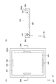
- FIG. 3 is a schematic perspective view showing the power storage module of FIG. 4 is an enlarged plan view of a part of the power storage module of FIG. 3 (a peripheral region of one opening 50a).
- the frame 50 of the power storage module 12 has a side surface 50 s extending in the stacking direction D ⁇ b> 1.
- the side surface 50s is a surface located outside as viewed from the stacking direction D1. Therefore, the second resin portion 54 has the side surface 50 s of the frame body 50.
- the side surface 50s of the frame 50 has a main body region 50s1 and a protruding region 50s2.
- Each of the main body region 50s1 and the protruding region 50s2 has a rectangular shape, for example.
- An opening 50a is provided in the main body region 50s1.
- the opening 50a functions as a liquid injection port for injecting an electrolytic solution into each internal space V, and after the electrolytic solution is injected, a pressure regulating valve 60 (for adjusting the pressure in each internal space V) It functions as a connection port in detail).
- the frame body 50 has a plurality of (here, four) openings 50a (openings 50a1 to 50a4). Specifically, two openings 50 a are provided on each side surface 50 s facing the longitudinal direction (X direction) of the frame body 50.
- the main body region 50 s 1 has an edge E that extends in a direction (Y direction) intersecting the stacking direction D 1 of the bipolar electrode 32.
- the protruding region 50 s 2 protrudes from the edge E so as to be separated from the opening 50 a in the stacking direction of the bipolar electrode 32.
- the pair of protruding regions 50s2 are arranged so as to sandwich the opening 50a.
- the protruding region 50s2 is provided with a length that extends beyond the entire length of the opening 50a along the edge E and protrudes from both sides of the opening 50a.
- one opening 50 a may have a first opening 52 a provided in the first resin portion 52 and a second opening 54 a provided in the second resin portion 54.
- Each first opening 52a communicates with the internal space V between the adjacent bipolar electrodes 32 and the second opening 54a.
- the first resin part 52 is provided with a plurality of first openings 52a
- the second resin part 54 is provided with a single second opening 54a that extends so as to cover the plurality of first openings 52a.
- the first opening 52 a may be provided in each first resin portion 52, or may be provided between adjacent first resin portions 52.
- Each of the first openings 52a and the second openings 54a has a rectangular shape, for example.
- each internal space V communicates with 14 internal spaces V. That is, each internal space V communicates with any one of the four openings 50a1 to 50a4.
- 14 first openings 52a are arranged in two rows in the short direction (Y direction) of the frame 50. ing. In each row, seven first openings 52a are arranged along the stacking direction D1. The 14 first openings 52a are arranged point-symmetrically with respect to the center P1 of the second opening 54a when viewed from the opening direction (X direction) of the opening 50a.
- the arrangement of the plurality of first openings 52a in each opening 50a may be determined as follows.
- the internal space V1 is arranged in the order from the other end (the lower side in FIG. 2) to the one end (the upper side in FIG. 2) of the stacked body 30. This is expressed as ⁇ V56.
- the seven first openings 52 a arranged in the first row are skipped eight steps from the other end side of the stacked body 30 to the internal space V 1.
- V9, V17, V25, V33, V41, V49, and the seven first openings 52a arranged in the second row are provided so as to communicate with the internal spaces V56, V48, V40, V32, V24, V16, and V8 in eight steps from one end side of 30.
- the first opening 52a is provided at a height position (position in the stacking direction D1) corresponding to the internal space V communicating with the first opening 52a, according to the above arrangement, the above point-symmetric arrangement is provided. Is realized.
- a point-symmetric arrangement can be realized in the same manner as the opening 50a1 by shifting the set of the internal space V to be communicated one step at a time with respect to the opening 50a1.
- the seven first openings 52a arranged in the first row are provided so as to communicate with the internal spaces V2, V10, V18, V26, V34, V42, V50, and the second
- the seven first openings 52a arranged in a row may be provided so as to communicate with the internal spaces V55, V47, V39, V31, V23, V15, and V7.
- the seven first openings 52a arranged in the first row are provided so as to communicate with the internal spaces V3, V11, V19, V27, V35, V43, and V51, and are arranged in the second row.
- the seven first openings 52a may be provided so as to communicate with the internal spaces V54, V46, V38, V30, V22, V14, and V6.
- the seven first openings 52a arranged in the first row are provided so as to communicate with the internal spaces V4, V12, V20, V28, V36, V44, and V52, and are arranged in the second row.
- the seven first openings 52a may be provided so as to communicate with the internal spaces V53, V45, V37, V29, V21, V13, and V5.
- the arrangement of the first openings 52a as described above that is, the correspondence between the first openings 52a and the internal spaces V
- the point-symmetric arrangement as described above can be realized for all the openings 50a1 to 50a4.
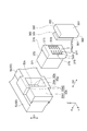
- FIG. 5 is an exploded perspective view of the pressure regulating valve 60 connected to the opening 50a of the frame 50.
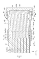
- FIG. FIG. 6 is a schematic cross-sectional view showing the configuration of the pressure regulating valve 60. Specifically, FIG. 6 shows seven first openings 52a (first openings 52a communicating with the internal spaces V1, V9, V17, V25, V33, V41, and V49) arranged in the first row of the openings 50a1. It is sectional drawing containing a cross section.
- the pressure regulating valve 60 includes a base member 70, a valve body 80 (elastic member), and a cover member 90 (pressing member).
- the base member 70 has a substantially rectangular parallelepiped outer shape, and is formed of, for example, polypropylene (PP), polyphenylene sulfide (PPS), modified polyphenylene ether (modified PPE), or the like.
- the base member 70 is connected to the opening 50a.
- the portion 72 including the side surface 71 (first side surface) facing the opening 50a of the base member 70 has a shape corresponding to the second opening 54a.
- the base member 70 is welded to the opening 50a by welding a part or all of the contact portion between the side surface 71 and the side surface 52s of the first resin portion 52 in a state where the portion 72 is inserted into the second opening 54a. It is fixed against.
- the welding of the side surface 71 and the side surface 52s is performed by, for example, hot plate welding.
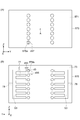
- FIG. 7A is a plan view showing the side surface 71
- FIG. 7B is a plan view showing a side surface 73 (second side surface) of the base member 70 facing the valve body 80.
- FIG. As shown in FIGS. 6 and 7, the base member 70 is provided with a plurality of (here, 14) communication holes 74 penetrating from the side surface 71 to the side surface 73. Each communication hole 74 communicates with one internal space V through one corresponding first opening 52a.
- the communication hole 74 includes a first communication portion 75 that is a side surface 71 side portion of the communication hole 74 and a second communication portion 76 that is a side surface 73 side portion of the communication hole 74.
- the first communication part 75 is formed in a rectangular cross section.
- a substantially rectangular parallelepiped space S ⁇ b> 1 is formed by the first communication portion 75.
- the opening end 75a (first opening end) on the opening 50a side of the first communication portion 75 includes a rectangular first opening 52a when viewed from the connection direction D2 (X direction) between the opening 50a and the pressure regulating valve 60. It is formed in size.
- the opening end 75b on the side connected to the second communication portion 76 of the first communication portion 75 is formed in a circular cross section.
- the inner diameter of the open end 75b is the same as the width d1 of the open end 75a in the stacking direction D1.
- the positions of the first openings 52a provided at the same relative positions (the same column and the same row) of the openings 50a1 to 50a4 are shifted by one stage as described above.
- the first opening 52a of the opening 50a1 communicating with the internal space V1 the first opening 52a of the opening 50a2 communicating with the internal space V2
- the arrangement of the first openings 52a of the opening 50a4 to be shifted is shifted by one step.
- the base member 70 of the pressure regulating valve 60 is connected to which opening 50a1 to 50a4. Also in this case, each first communication part 75 needs to communicate with the corresponding first opening 52a. Specifically, when the base member 70 is connected to the opening 50a1, the first communication portion 75 that communicates with the first opening 52a corresponding to the internal space V1 is used when the base member 70 is connected to the openings 50a2 to 50a4. Needs to communicate with the first openings 52a corresponding to the internal spaces V2 to V4, respectively.
- the width d1 of the opening end 75a in the stacking direction D1 is the width of one structure repeated in the stacked body 30 (that is, the above-described shift width of one step) and the number of openings 50a. It is set to a value greater than the multiplication value.
- the width of one structure repeated in the stacked body 30 is a width d2 (see FIG. 2) in the stacking direction D1 of a portion where one electrode plate 34 and one internal space V are combined. That is, the multiplication value (“d2 ⁇ 4” in the present embodiment) is obtained when the first openings 52a in the respective openings 50a are arranged as described above (more specifically, relative positions corresponding to each other between the openings 50a).
- the width necessary to include (range in the stacking direction D1) is shown.
- the relationship “d1 ⁇ d2 ⁇ 4” is established.
- the plurality of open ends 75a are arranged in point symmetry with respect to an axis A (see FIG. 5) passing through the center P2 of the side surface 71 and orthogonal to the side surface 71. Yes. Further, the portion 72 connected to the opening 50 a of the base member 70 is formed point-symmetrically with respect to the axis A. Further, the above-described center P1 (the center of the second opening 54a viewed from the opening direction of the opening 50a) is located on the axis A.
- the relative arrangement of the plurality of opening ends 75a with respect to the opening 50a is the same in any of the two states (postures) of the pressure regulating valve 60 that are in an inverted relationship with respect to the axis A.
- the pressure regulating valve 60 can be normally connected to the opening 50a in any of the two states. That is, even if the pressure regulating valve 60 shown in FIG. 5 is turned upside down (rotated 180 degrees around the axis A), the pressure regulating valve 60 can be normally connected to the opening 50a. As a result, the pressure adjustment valve 60 can be easily connected to the opening 50a. Further, it is possible to prevent erroneous assembly such that the pressure regulating valve 60 is connected to the opening 50a in the wrong direction.
- the second communication portion 76 is formed in a circular cross section.
- the second communication portion 76 penetrates from the opening end 75 b of the first communication portion 75 to the opening end 76 a (second opening end) on the side surface 73 side of the second communication portion 76.
- the open end 76a is formed in a circular shape.
- the inner diameter d3 of the opening end 76a is larger than the inner diameter of the opening end 75b (that is, the width d1 of the opening end 75a in the stacking direction D1) (d3> d1). That is, the second communication portion 76 forms a tapered space S2 having an inner diameter that increases from the opening end 75b toward the opening end 76a.
- Such a 2nd communication part 76 may be formed by injection molding etc., for example.
- the second communication portion 76 connected to the seven first openings 52a in the first row is located at the center position of the opening end 76a rather than the center position of the opening end 75b. Extends so as to be located above.
- the second communicating portion 76 connected to the seven first openings 52a in the second row extends so that the center position of the opening end 76a is located below the center position of the opening end 75b.
- FIG. 7B the plurality of open ends 76 a are brought close to the center position of the side surface 73. Thereby, the compactness of the valve body 80 which needs to block all the open ends 76a is achieved.
- the valve body 80 is formed of an elastic member such as rubber, for example.
- the valve body 80 has a rectangular parallelepiped shape, for example.
- the valve body 80 is disposed so as to block a plurality of open ends 76 a provided in the base member 70.
- the cover member 90 is a box-shaped member having a rectangular plate-shaped bottom wall portion 91 and a side wall portion 92 erected on the edge of the bottom wall portion 91.
- the cover member 90 is made of, for example, polypropylene (PP), polyphenylene sulfide (PPS), modified polyphenylene ether (modified PPE), or the like.
- PP polypropylene
- PPS polyphenylene sulfide
- modified PPE modified polyphenylene ether
- the cover member 90 accommodates the valve body 80 in the groove 93 and functions as a pressing member for pressing the valve body 80 against the side surface 73 of the base member 70. Specifically, as shown in FIG.
- the end 92 a of the side wall 92 is positioned with respect to the side surface 73 of the base member 70 in a state where the valve body 80 is positioned and accommodated in the groove 93 of the cover member 90.
- a method for fixing the end portion 92a and the side surface 73 is not particularly limited.
- laser welding, hot plate welding, and fastening using a fastening member such as a bolt can be used.
- the cover member 90 is formed of a laser-transmitting resin
- the base member 70 is formed of a laser-absorbing resin
- the laser is irradiated from the cover member 90 side. The boundary portion with the cover member 90 can be melted and joined.
- the thickness (width in the X direction) of the valve body 80 during normal (non-compression) is larger than the height d4 from the bottom surface 93a of the groove portion 93 to the end portion 92a of the side wall portion 92. That is, the compression rate of the valve body 80 is defined by the height d4.
- the compression rate of the valve body 80 is, for example, when the pressure in the communication hole 74 (that is, the pressure in the internal space V communicated with the communication hole 74) is equal to or higher than a predetermined set value. Is adjusted in advance so as to release the blockage of the open end 76a of the communication hole 74.
- each groove part 77 is formed in a slit shape extending in a direction (X direction and Y direction) orthogonal to the stacking direction D1.
- Each groove portion 77 is provided at a position outside the corresponding opening end 76a in the direction (Y direction) orthogonal to the stacking direction D1 and the connection direction D2.
- a part of the valve body 80 (specifically, the open end) as shown in FIG.
- the portion that closes 76a and its peripheral portion) is deformed so as to be separated from the side surface 73, and the valve is in an open state in which the closing of the opening end 76a is released.
- the open end 76a released from the blockage communicates with the groove 77 corresponding to the open end 76a, and the gas in the corresponding internal space V is discharged from the open end 76a to the groove 77.
- the valve body 80 After that, when the pressure in the internal space V becomes less than the set value, the valve body 80 returns to the original state, and the opening end 76a is again in the closed state (see FIG. 8A). Become. With the above opening / closing operation, the pressure adjusting valve 60 appropriately adjusts the pressure in the internal space V.
- the distance d5 between the opening end 76a and the groove 77 corresponding to the opening end 76a is equal to the opening end 76a and another opening end adjacent to the opening end 76a. It is shorter than the distance d6 with respect to 76a (d5 ⁇ d6).
- the base member 70 has a plurality of (here, seven) groove portions as viewed from the direction facing the side surface 73 (X direction).
- a circulation space S3 is defined in which the gas discharged from the internal space V is circulated.
- the distribution space S3 is formed in a substantially rectangular parallelepiped shape.
- the circulation space S3 extends in the stacking direction D1 so as to connect the outer end portions of the seven groove portions 77 arranged along the stacking direction D1 when viewed from the direction facing the side surface 73.
- the plurality of groove portions 77 and the distribution space S3 are formed by, for example, injection molding.
- the base member 70 is provided with an exhaust port 78 that allows the circulation space S3 to communicate with the outside.
- the outer opening end of the exhaust port 78 is provided on a side surface 79 that faces in a direction orthogonal to the connection direction D2 of the base member 70 (Y direction as an example in the present embodiment).
- the valve body 80 is arranged so as not to cover a part of the circulation space S3, but may be arranged so as to cover the whole circulation space S3. Good. Further, the valve body 80 is disposed so as to cover the entire groove portion 77, but may be disposed so as not to cover at least a part of the groove portion 77.
- the power storage module 12 of the present embodiment includes the electrode plate 34, the positive electrode 36 provided on one surface of the electrode plate 34, and the negative electrode 38 provided on the other surface of the electrode plate.
- a laminated body 30 in which a plurality of bipolar electrodes 32 are laminated, and an opening 50 a that holds an edge 34 a of the electrode plate 34 and communicates with a plurality of internal spaces V between adjacent bipolar electrodes 32 in the laminated body 30 are provided.
- a frame 50 and a pressure regulating valve 60 connected to the opening 50a are provided.
- the pressure regulating valve 60 is provided with a plurality of communication holes 74 communicating with each of the plurality of internal spaces V through the openings 50a, and the base member 70 connected to the openings 50a and the openings 50a side of the plurality of communication holes 74. And a cover member 90 that presses the valve body 80 against the base member 70.
- the valve body 80 is disposed so as to close the open end 76a located on the opposite side of the open end 75a.
- the pressure adjustment valve 60 includes the base member 70, the valve body 80, and the cover member 90 provided with a plurality of communication holes 74, so that before the pressure adjustment valve 60 is connected to the opening 50 a, Inspection of the pressure regulating valve 60 can be performed. For example, the pressure value when the opening of the open end 76 a of the communication hole 74 by the valve body 80 is released by sending air into the communication hole 74 from the open end 75 a of each communication hole 74 of the base member 70. Can be confirmed. Therefore, according to the power storage module 12, the pressure adjustment valve 60 can be easily inspected (for example, inspection for guaranteeing the valve opening pressure) before the pressure adjustment valve 60 is assembled.
- the power storage module 12 includes a plurality of (four in this embodiment) pressure regulating valves 60.
- the frame 50 is provided with a plurality (four) of openings 50a (50a1 to 50a4) to which the pressure regulating valve 60 is connected.
- Each of the plurality of openings 50a communicates with a different internal space V (in this embodiment, a set of 14 different internal spaces V) for each opening 50a.
- V internal space
- the number of internal spaces V communicated with one opening 50a (that is, one pressure regulating valve 60) compared to the case where only one opening 50a is provided.
- the number of internal spaces V that need to be adjusted in pressure and the number of communication holes 74 that need to be provided in one pressure adjusting valve 60 can be reduced.
- the cross-sectional area of the one communication hole 74 of the pressure regulating valve 60 can be increased, and the air flow in the communication hole 74 can be made smooth.
- a laminate process First, for example, a plurality of bipolar electrodes 32 are stacked via a separator 40 to obtain a stacked body 30.
- the first resin portion 52 is formed on the edge portion 34a of the electrode plate 34 of each bipolar electrode 32 by, for example, injection molding before the lamination step.
- the laminating process a configuration excluding the second resin portion 54 in the configuration shown in FIG. 2 is obtained.
- the second resin portion 54 is formed by, for example, injection molding (see FIG. 2).
- the second resin portion 54 is formed by pouring the resin material 54 ⁇ / b> P of the second resin portion 54 having fluidity into the mold M.
- the frame body 50 having the first resin portion 52 and the second resin portion 54 is formed.
- the mold M is a nesting for forming a first portion M1 that forms the outer edges of the main body region 50s1 and the protruding region 50s2 (see FIG. 4) on the side surface 50s of the frame 50, and a second opening 54a of the opening 50a. 2 parts M2.
- the resin material 54P of the second resin portion 54 flows in a direction that intersects the stacking direction D1 of the bipolar electrode 32. For example, after the resin material 54P of the second resin portion 54 flows between the pair of first portions M1 that are arranged to face each other, the resin material 54P collides with the second portion M2, and the two resin materials 54P along the periphery of the second portion M2. Divided into The resin material 54P of the second resin portion 54 divided into two flows between the first portion M1 and the second portion M2, respectively, and then merges to flow between the pair of first portions M1.
- the first resin portion 52 that is a part of the frame body 50 is formed before the lamination step, and the second resin portion 54 that is the remaining portion of the frame body 50 is formed after the lamination step.
- Electrolytic solution injection process Next, an electrolytic solution is injected into the frame 50 from the opening 50 a provided in the frame 50.
- the electrolyte solution is injected using a dedicated jig or the like.
- the pressure regulating valve 60 is prepared. As described above, the pressure regulating valve 60 is formed by assembling the base member 70, the valve body 80, and the cover member 90 together. Thereby, the pressure regulating valve 60 having a configuration in which the base member 70, the valve body 80, and the cover member 90 are integrated (unitized) is obtained.
- the pressure regulating valve 60 is inspected. Specifically, the operation of the pressure regulating valve 60 is inspected by sending air into the communication holes 74 from the open ends 75 a of the communication holes 74 provided in the base member 70. The operation of sending air from each open end 75a into each communication hole 74 may be performed using, for example, a dedicated jig. In the inspection process, the pressure value when the closing of the opening end 76a by the valve body 80 is released is confirmed for each communication hole 74. Then, the pressure value is compared with a preset pressure value.
- the inspected pressure regulating valve 60 is determined to be normal.
- the inspected pressure regulating valve 60 is determined to be abnormal.
- the inspected pressure regulating valve 60 determined to be normal in the inspection process is connected to the opening 50 a of the frame body 50. Specifically, as described above, the portion 72 of the base member 70 is inserted into the second opening 54a. Then, a part or all of the contact portion between the side surface 71 and the side surface 52s of the first resin portion 52 is welded by, for example, hot plate welding. Thereby, it will be in the state where pressure regulation valve 60 was assembled to opening 50a. Thereafter, as shown in FIG. 1, a plurality of power storage modules 12 are stacked via the conductive plate 14. A positive electrode terminal 24 and a negative electrode terminal 26 are respectively connected in advance to the conductive plates 14 located at both ends in the stacking direction D1.
- a pair of restraining plates 16A and 16B are disposed at both ends in the stacking direction D1 with the insulating film 22 interposed therebetween.
- the shaft portion of the bolt 18 is inserted into the insertion hole 16A1 of the restraining plate 16A, and is inserted into the insertion hole 16B1 of the restraining plate 16B.
- the nut 20 is screwed onto the tip of the bolt 18 protruding from the restraining plate 16B. In this way, the power storage device 10 shown in FIG. 1 is manufactured.
- the method for manufacturing an electricity storage module includes a stacking process, a frame forming process, a preparation process, an inspection process, and a pressure regulating valve connecting process.
- the preparation step the pressure regulating valve 60 in which the base member 70, the valve body 80, and the cover member 90 are integrated is prepared.
- the inspection process the operation of the pressure regulating valve 60 is inspected by sending air into the communication holes 74 from the open ends 75 a of the communication holes 74 of the base member 70.
- the pressure regulating valve 60 includes the base member 70 provided with the plurality of communication holes 74, the valve body 80, and the cover member 90, thereby connecting the pressure regulating valve 60 to the opening 50a of the frame body 50.
- a check of the pressure regulating valve 60 can be performed. Therefore, according to the manufacturing method, it is possible to easily inspect the pressure regulating valve 60 (for example, to inspect the valve opening pressure) before the pressure regulating valve 60 is assembled.
- an electrical storage module is not limited to the said form.
- the plurality of first openings 52a are arranged point-symmetrically with respect to the center P1 of the second opening 54a when viewed from the opening direction (X direction) of the opening 50a.
- the configuration has been described.
- the plurality of first openings 52a in each opening 50a may be disposed so as to be included in the opening ends 75a of the corresponding base members 70 when viewed from the connection direction D2, and the plurality of first openings 52a are not necessarily provided. It need not be arranged point-symmetrically.
- the arrangement of the first openings 52a illustrated in the above embodiment may be appropriately changed between the plurality of openings 50a.
- a first opening 52a that communicates with the internal space V2 is provided in the opening 50a1 instead of the first opening 52a that communicates with the internal space V1, and a first communication that communicates with the internal space V2 is provided at the opening 50a2.
- a first opening 52a communicating with the internal space V1 may be provided.
- the arrangement of the plurality of first openings 52a in each of the opening 50a1 and the opening 50a2 is not the point-symmetric arrangement as described above, but any first opening 52a corresponds to the opening end 75a corresponding to the connection direction D2. It is arranged to be included in.
- the base member 70 may be a single member integrally formed as in the first embodiment, or may be composed of a plurality of members.
- the base member 70 may be a member formed by joining a plurality of members by welding or the like.
- the power storage device 10 ⁇ / b> A is different from the power storage device 10 in that it includes a power storage module 12 ⁇ / b> A instead of the power storage module 12, and is otherwise similar to the power storage device 10.
- the power storage module 12A is different from the power storage module 12 in that a pressure adjustment valve 160 is provided instead of the pressure adjustment valve 60, and the other points are the same as those of the power storage module 12.
- FIG. 10 is an exploded perspective view of the pressure regulating valve 160 connected to the opening 50a of the frame 50.
- FIG. FIG. 11 is a schematic cross-sectional view showing the configuration of the pressure regulating valve 160. Specifically, FIG. 11 shows seven first openings 52a (first openings 52a communicating with the internal spaces V1, V9, V17, V25, V33, V41, and V49) arranged in the first row of the openings 50a1. It is sectional drawing containing a cross section.
- the pressure adjustment valve 160 includes a first base member 170, a second base member 180, a valve body 190 (elastic member), and a cover member 1100 (pressing member). is doing.
- the first base member 170 has a substantially rectangular parallelepiped outer shape, and is formed of, for example, polypropylene (PP), polyphenylene sulfide (PPS), or modified polyphenylene ether (modified PPE).
- the first base member 170 is connected to the opening 50a.
- the portion 172 including the side surface 171 (first side surface) facing the opening 50a of the first base member 170 has a shape corresponding to the second opening 54a.
- the first base member 170 is opened when a part or all of the contact portion between the side surface 171 and the side surface 52s of the first resin portion 52 is welded in a state where the portion 172 is inserted into the second opening 54a. It is fixed with respect to 50a.
- the side surface 171 and the side surface 52s are welded by, for example, hot plate welding, laser transmission welding, ultrasonic welding, or the like.
- FIG. 12A is a plan view showing the side surface 171
- FIG. 12B is a plan view showing the side surface 173 (second side surface) of the first base member 170 facing the second base member 180. It is.
- the first base member 170 is provided with a plurality of (here, 14) first communication holes 174 that penetrate from the side surface 171 to the side surface 173.
- Each first communication hole 174 communicates with one internal space V through one corresponding first opening 52a.
- the first communication hole 174 includes a first communication portion 175 that is a side surface 171 side portion of the first communication hole 174 and a second communication portion 176 that is a side surface 173 side portion of the first communication hole 174.
- the first communication part 175 has a rectangular cross section.
- the first communication portion 175 forms a substantially rectangular space S11.
- the opening end 175a on the opening 50a side of the first communication portion 175 is formed to have a size including the rectangular first opening 52a when viewed from the connection direction D2 (X direction) between the opening 50a and the first base member 170.
- the opening end 175b on the side connected to the second communication portion 176 of the first communication portion 175 has a circular cross section.
- the inner diameter of the open end 175b is the same as the width d11 of the open end 175a in the stacking direction D1.
- the positions of the first openings 52a provided at the same relative positions (the same column and the same row) of the openings 50a1 to 50a4 are shifted by one stage as described above.
- the first opening 52a of the opening 50a1 communicating with the internal space V1 the first opening 52a of the opening 50a2 communicating with the internal space V2
- the arrangement of the first openings 52a of the opening 50a4 to be shifted is shifted by one step.
- each first communication portion 175 needs to communicate with the corresponding first opening 52a.
- the first base member 170 is connected to the opening 50a1
- the first communication portion 175 that communicates with the first opening 52a corresponding to the internal space V1 has the first base member 170 in the openings 50a2 to 50a4.
- the width d11 of the opening end 175a in the stacking direction D1 is the width of one structure repeated in the stacked body 30 (that is, the above-described shift width of one step) and the number of openings 50a. It is set to a value greater than the multiplication value.
- the width of one structure repeated in the stacked body 30 is a width d2 (see FIG. 2) in the stacking direction D1 of a portion where one electrode plate 34 and one internal space V are combined. That is, the multiplication value (“d2 ⁇ 4” in the present embodiment) is obtained when the first openings 52a in the respective openings 50a are arranged as described above (more specifically, relative positions corresponding to each other between the openings 50a).
- the width necessary to include (range in the stacking direction D1) is shown.
- the relationship “d11 ⁇ d2 ⁇ 4” is established.
- the same first base member 170 pressure adjusting valve 160
- the same first base member 170 pressure adjusting valve 160
- the number of parts can be reduced.
- it is not necessary to use a pressure regulating valve 160 having a different standard for each opening 50a it is possible to prevent the occurrence of erroneous assembly such as connecting a pressure regulating valve 160 having a standard that does not conform to the opening 50a. .
- the plurality of open ends 175a are arranged point-symmetrically with respect to an axis A (see FIG. 10) passing through the center P2 of the side surface 171 and orthogonal to the side surface 171. Yes. Further, the portion 172 connected to the opening 50 a of the first base member 170 is formed with point symmetry with respect to the axis A. Further, the above-described center P1 (the center of the second opening 54a viewed from the opening direction of the opening 50a) is located on the axis A.
- the relative arrangement of the plurality of opening ends 175a with respect to the opening 50a is the same in any of the two states (postures) of the first base member 170 that are in an inverted relationship with respect to the axis A. .
- the first base member 170 can be normally connected to the opening 50a. That is, even if the first base member 170 shown in FIG. 10 is turned upside down (rotated 180 degrees around the axis A), the first base member 170 can be normally connected to the opening 50a. As a result, the first base member 170 can be easily connected to the opening 50a.
- the second communication part 176 has a circular cross section.
- the second communication portion 176 penetrates from the opening end 175 b of the first communication portion 175 to the opening end 176 a on the side surface 173 side of the second communication portion 176.
- the open end 176a is formed in a circular shape.
- the inner diameter d13 of the opening end 176a is larger than the inner diameter of the opening end 175b (that is, the width d11 of the opening end 175a in the stacking direction D1) (d13> d11). That is, the second communication portion 176 forms a tapered space S12 having an inner diameter that increases from the opening end 175b toward the opening end 176a.
- Such a second communication portion 176 can be formed by, for example, injection molding or the like.
- the second communication portion 176 connected to the seven first openings 52a in the first row has a center position of the opening end 176a rather than a center position of the opening end 175b. Extends so as to be located above.
- the second communicating portion 176 connected to the seven first openings 52a in the second row extends so that the center position of the opening end 176a is located below the center position of the opening end 175b.
- the plurality of open ends 176 a are brought close to the center position of the side surface 173.
- the second base member 180 has a substantially rectangular parallelepiped outer shape, and is joined to the side surface 173 of the first base member 170 on one side surface 181.
- the side surface 181 and the side surface 173 can be welded by, for example, hot plate welding.
- the second base member 180 is formed slightly larger than the first base member 170 when viewed from the connection direction D2, but the second base member 180 is the same as the first base member 170. The same size may be formed, or the first base member 170 may be formed smaller.
- FIG. 13A is a plan view showing the side surface 181
- FIG. 13B is a plan view showing the side surface 182 (second side surface) of the second base member 180 that faces the valve body 190.
- the second base member 180 is provided with a plurality of (here, 14) second communication holes 183 penetrating from the side surface 181 to the side surface 182.
- the second communication hole 183 has a circular cross section.
- Each second communication hole 183 communicates with one internal space V via a corresponding first communication hole 174.
- the inner diameter of the opening end 183a of the second communication hole 183 on the first base member 170 side coincides with the inner diameter d13 of the opening end 176a of the first communication hole 174.
- the first base member 170 and the second base member 180 are joined so that the opening end 176a and the opening end 183a corresponding to each other as seen from the connection direction D2 overlap each other.
- the inner diameter d14 of the opening end 183b on the valve body 190 side of the second communication hole 183 is smaller than the inner diameter of the opening end 183a (that is, the inner diameter d13 of the opening end 176a) (d14 ⁇ d13). That is, the second communication hole 183 forms a tapered space S13 having an inner diameter that decreases from the opening end 183a toward the opening end 183b.
- Such a second communication hole 183 can be formed by, for example, injection molding or the like.
- the inner diameter of the opening end 183a and the inner diameter d13 of the opening end 176a do not have to coincide with each other.
- the inner diameter of the open end 183a is made smaller than the inner diameter d13, an effect of allowing a positional shift at the time of joining can be achieved.
- the plurality of opening ends 176a and the plurality of opening ends 183a are all arranged point-symmetrically with respect to the axis A. According to this configuration, in any of the two states (postures) of the first base member 170 (or the second base member 180) that are reversed with respect to the axis A, a plurality of openings with respect to the plurality of opening ends 176a. The arrangement of the end 183a is the same. For this reason, it becomes possible to normally join the second base member 180 to the first base member 170 in either of the two states.
- the second base member 180 can be normally joined to the first base member 170 even if the second base member 180 is turned upside down (rotated 180 degrees around the axis A) with respect to the first base member 170. .
- the second base member 180 can be easily joined to the first base member 170.
- it is possible to prevent erroneous assembly such that the second base member 180 is joined to the first base member 170 in an incorrect direction.
- the valve body 190 is formed of an elastic member such as rubber.
- the valve body 190 has a rectangular parallelepiped shape, for example.
- the valve body 190 is disposed so as to close the plurality of open ends 183 b provided in the second base member 180.
- the cover member 1100 is a box-shaped member having a rectangular plate-shaped bottom wall portion 1101 and a side wall portion 1102 erected on the edge of the bottom wall portion 1101.
- the cover member 1100 is made of, for example, polypropylene (PP), polyphenylene sulfide (PPS), modified polyphenylene ether (modified PPE), or the like.
- PP polypropylene
- PPS polyphenylene sulfide
- modified PPE modified polyphenylene ether
- the cover member 1100 accommodates the valve body 190 in the groove 1103 and functions as a pressing member for pressing the valve body 190 against the side surface 182 of the second base member 180. Specifically, as shown in FIG.
- the end portion 1102 a of the side wall portion 1102 is formed on the side surface 182 of the second base member 180 in a state where the valve body 190 is positioned and accommodated in the groove portion 1103 of the cover member 1100. It is fixed against.
- a method for fixing the end portion 1102a and the side surface 182 is not particularly limited. For example, laser welding, hot plate welding, and fastening using a fastening member such as a bolt can be used.
- the cover member 1100 is formed of a laser-transmitting resin
- the second base member 180 is formed of a laser-absorbing resin
- the laser is irradiated from the cover member 1100 side, whereby the second The boundary portion between the base member 180 and the cover member 1100 can be melted and joined.
- the normal thickness (in the non-compressed state) of the valve body 190 (the width in the X direction) is larger than the height d15 from the bottom surface 1103a of the groove 1103 to the end 1102a of the side wall 1102. That is, the compression rate of the valve body 190 is defined by the height d15.
- the compression rate of the valve body 190 is, for example, when the pressure in the second communication hole 183 (that is, the pressure in the internal space V communicated with the second communication hole 183) is equal to or higher than a predetermined set value.
- the valve body 190 is adjusted in advance so as to release the blockage of the opening end 183b of the second communication hole 183.
- each groove portion 184 is formed in a slit shape extending in a direction (X direction and Y direction) orthogonal to the stacking direction D1.
- Each groove portion 184 is provided at a position outside the corresponding opening end 183b in the direction (Y direction) orthogonal to the stacking direction D1 and the connection direction D2.
- each of the second communication holes 183 communicates with the corresponding internal space V. Therefore, a portion of the valve body 190 that closes the opening end 183b of the second communication hole 183 is connected to the second communication hole 183. A pressure equivalent to that of the corresponding internal space V is applied.
- the release of the closing of the opening end 183b by the valve body 190 is performed when the pressure in the corresponding internal space V is equal to or higher than a predetermined set value, so that the compression rate of the valve body 190 is increased. It is prescribed. For this reason, when the pressure in the corresponding internal space V is less than the set value, the closed state in which the opening end 183b is blocked by the valve body 190 is maintained as shown in FIG. Is done.
- the valve body 190 returns to the original state, so that the open end 183b is closed again (see (A) in FIG. 14). Become. With the above opening / closing operation, the pressure adjustment valve 160 appropriately adjusts the pressure in the internal space V.
- the distance d16 between the opening end 183b and the groove portion 184 corresponding to the opening end 183b is the other opening end adjacent to the opening end 183b and the opening end 183b. It is shorter than the distance d17 with respect to 183b (d16 ⁇ d17).
- the second base member 180 includes a plurality (seven in this case) as viewed from the direction facing the side surface 182 (X direction).
- a flow space S14 is defined which is connected to the groove portion 184 and allows the gas released from the internal space V to flow therethrough.
- the distribution space S14 is formed in a substantially rectangular parallelepiped shape.
- the distribution space S14 extends in the stacking direction D1 so as to connect the outer end portions of the seven groove portions 184 arranged along the stacking direction D1 when viewed from the direction facing the side surface 182.
- the plurality of grooves 184 and the distribution space S14 are formed by, for example, injection molding or the like.
- the second base member 180 is provided with an exhaust port 185 that allows the circulation space S14 to communicate with the outside.
- the outer opening end of the exhaust port 185 is provided on a side surface 186 that faces in a direction orthogonal to the connection direction D2 of the second base member 180 (Y direction as an example in the present embodiment).
- valve body 190 is arranged so as not to cover a part of the circulation space S14, but may be arranged so as to cover the whole circulation space S14. Good. Further, although the valve body 190 is disposed so as to cover the entire groove portion 184, it may be disposed so as not to cover at least a part of the groove portion 184.
- the power storage module 12 ⁇ / b> A of this embodiment includes a bipolar plate including the electrode plate 34, the positive electrode 36 provided on one surface of the electrode plate 34, and the negative electrode 38 provided on the other surface of the electrode plate 34.
- a pressure regulating valve 160 connected to the opening 50a.
- the pressure regulating valve 160 is provided with a plurality of first communication holes 174 communicating with each of the plurality of internal spaces V through the openings 50a, and a first base member 170 connected to the openings 50a and a plurality of first communication holes.
- a plurality of second communication holes 183 communicating with each of the holes 174 are provided, and the second base member 180 joined to the side surface 173 of the first base member 170 and the opening 50a side of the plurality of second communication holes 183 are It has the valve body 190 arrange
- the electrolyte solution can be injected into each internal space V using the first base member 170 provided with a plurality of first communication holes 174 communicating with each of the plurality of internal spaces V. It is possible. Specifically, at the time of manufacturing the power storage module 12A, the first base member 170 is connected to the opening 50a before the first base member 170 is joined to the second base member 180, whereby each first communication hole 174 is connected. It is possible to inject the electrolytic solution into each internal space V via the. In addition, it is possible to perform an inspection of the pressure regulating valve 160 using the second base member 180 provided with a plurality of second communication holes 183.
- a unit including the second base member 180, the valve body 190, and the cover member 1100.
- a unit including the second base member 180, the valve body 190, and the cover member 1100.
- the valve body 190 blocks the opening end 183b of the second communication hole 183.
- the pressure value when released can be confirmed. Therefore, according to the electricity storage module 12A, the workability of the electrolyte solution injection is improved, and the inspection of the pressure adjustment valve 160 (for example, the inspection for guaranteeing the valve opening pressure) is easy before the pressure adjustment valve 160 is assembled. Can be done.
- the power storage module 12A includes a plurality (four in this embodiment) of pressure regulating valves 160.
- the frame 50 is provided with a plurality (four) of openings 50a (50a1 to 50a4) to which the pressure regulating valve 160 is connected.
- Each of the plurality of openings 50a communicates with a different internal space V (in this embodiment, a set of 14 different internal spaces V) for each opening 50a.
- V internal space
- the number of internal spaces V communicated with one opening 50a (that is, one pressure regulating valve 160) as compared with the case where only one opening 50a is provided.
- the number of internal spaces V that need to be adjusted in pressure can be reduced, and the number of first communication holes 174 and second communication holes 183 that need to be provided in one pressure adjustment valve 160 can be reduced.
- the cross-sectional area of the 1st communicating hole 174 and the 2nd communicating hole 183 of the pressure regulation valve 160 can be enlarged, and the distribution
- the second communication portion 176 (the portion on the second base member 180 side) of the first communication hole 174 has a cross-sectional area that increases from the opening 50a side toward the second base member 180 side. It is formed in a tapered shape.
- the second communication hole 183 is formed in a tapered shape with a cross-sectional area that decreases from the first base member 170 side toward the valve body 190 side.
- the cross-sectional area of the flow path (flow path formed by the second communication portion 176 and the second communication hole 183) from the internal space V toward the valve body 190 is once increased and then reduced.
- pressure loss can be suppressed, and gas flow in the communication holes (the first communication hole 174 and the second communication hole 183) can be made smooth.
- the opening area of the opening end 183b of the second communication hole 183 is the opening 50a of the tapered portion of the first communication hole 174 (that is, the second communication part 176).
- the opening area of the side opening end is larger than the opening area (the area of the circle having an inner diameter of d11). That is, in this embodiment, “d14> d11” is established. According to this configuration, since the sectional area on the outlet side of the flow path from the internal space V toward the valve body 190 is larger than the sectional area on the inlet side, pressure loss can be more effectively suppressed.
- the second communication hole 183 is formed from the first base member 170 side so as to narrow the opening width widened by the second communication portion 176. It is formed in a tapered shape in which the cross-sectional area becomes smaller toward the body 190 side. However, when it is allowed to further increase the opening width expanded by the second communication portion 176 in terms of space, the second communication hole 183 has a cross-sectional area that increases from the first base member 170 side toward the valve body 190 side. You may form in the taper shape which becomes large. Also in this case, the second communication hole 183 can be molded by injection molding or the like. In addition, the pressure loss can be more effectively suppressed by providing the cross-sectional area of the flow path from the internal space V toward the valve body 190 toward the outlet side from the inlet side.
- the width (inner diameter d13) of the opening end 176a on the second base member 180 side of the first communication hole 174 in the stacking direction D1 is the width d11 of the opening end 175a on the opening 50a side of the first communication hole 174 in the stacking direction D1. Bigger than. According to this configuration, the opening width (inner diameter d13) of the joint portion between the first communication hole 174 and the second communication hole 183 can be appropriately ensured. Thereby, for example, when the first base member 170 and the second base member 180 are joined by heat (for example, hot plate welding), it is possible to suppress the opening of the joint portion from being blocked.
- heat for example, hot plate welding
- the bipolar electrode 32 is stacked via the separator 40 to obtain the stacked body 30.
- the first resin portion 52 is formed on the edge portion 34a of the electrode plate 34 of each bipolar electrode 32 by, for example, injection molding before the lamination step.
- the laminating process a configuration excluding the second resin portion 54 in the configuration shown in FIG. 2 is obtained.
- the second resin portion 54 is formed by, for example, injection molding (see FIG. 2).
- the second resin portion 54 is formed by pouring the resin material 54 ⁇ / b> P of the second resin portion 54 having fluidity into the mold M.
- the frame body 50 having the first resin portion 52 and the second resin portion 54 is formed.
- the mold M is a nesting for forming a first portion M1 that forms the outer edges of the main body region 50s1 and the protruding region 50s2 (see FIG. 4) on the side surface 50s of the frame 50, and a second opening 54a of the opening 50a. 2 parts M2.
- the resin material 54P of the second resin portion 54 flows in a direction that intersects the stacking direction D1 of the bipolar electrode 32. For example, after the resin material 54P of the second resin portion 54 flows between the pair of first portions M1 that are arranged to face each other, the resin material 54P collides with the second portion M2, and the two resin materials 54P along the periphery of the second portion M2. Divided into The resin material 54P of the second resin portion 54 divided into two flows between the first portion M1 and the second portion M2, respectively, and then merges to flow between the pair of first portions M1.
- the first resin portion 52 that is a part of the frame body 50 is formed before the lamination step, and the second resin portion 54 that is the remaining portion of the frame body 50 is formed after the lamination step.
- the first base member 170 is connected to the opening 50a. Specifically, as described above, the portion 172 of the first base member 170 is inserted into the second opening 54a. Then, a part or all of the contact portion between the side surface 171 and the side surface 52s of the first resin portion 52 is welded by, for example, hot plate welding, laser transmission welding, ultrasonic welding, or the like. Thereby, the 1st base member 170 is fixed to opening 50a.
- FIG. 15A a plurality of internal spaces V (in the present embodiment, the first base) via a plurality of first communication holes 174 provided in the first base member 170.
- An electrolyte is injected into each of the 14 internal spaces V) communicating with the opening 50a to which the member 170 is connected.
- the amount of liquid for each internal space V can be managed.
- a vacuum is drawn to each internal space V through the plurality of first communication holes 174. (Work to extract air) may be performed. Thereby, the airtightness of each internal space V can be inspected before the injection of the electrolytic solution.
- the injection of the electrolytic solution through the first base member 170 may be performed using a dedicated jig or the like.
- a pressure regulating valve sub-module that is a unit including the second base member 180, the valve body 190, and the cover member 1100 is prepared.
- the pressure regulating valve submodule is formed by assembling the second base member 180, the valve body 190, and the cover member 1100 together.
- the pressure regulating valve submodule SM prepared in the preparation step is inspected. Thereby, it can be confirmed whether the function as the pressure regulating valve 160 is normally exhibited after the assembly. Specifically, the operation of the pressure regulating valve submodule SM is inspected by sending air into the second communication holes 183 from the open ends 183a of the second communication holes 183 provided in the second base member 180. . The operation of sending air from each open end 183a into each second communication hole 183 may be performed using, for example, a dedicated jig. In the inspection process, the pressure value when the closing of the opening end 183 b by the valve body 190 is released is confirmed for each second communication hole 183.
- the pressure value is compared with a preset pressure value. For example, if the error between the pressure value and a preset pressure value is equal to or less than the allowable error, it is determined that the valve opening pressure of the valve body 190 for the inspected second communication hole 183 is normal. On the other hand, when the error is larger than the allowable error, it is determined that the valve opening pressure of the valve body 190 for the inspected second communication hole 183 is abnormal. When it is determined by the above inspection that the valve opening pressures of the valve bodies 190 are normal for all the second communication holes 183, the inspected pressure regulating valve submodule SM is determined to be normal. On the other hand, when it is determined that the valve opening pressure of the valve body 190 is abnormal with respect to at least one second communication hole 183, the inspected pressure regulating valve submodule SM is determined to be abnormal.
- the first base member 170 and the inspected pressure regulating valve sub-module SM determined to be normal in the inspection process so that the plurality of first communication holes 174 and the plurality of second communication holes 183 communicate with each other.
- the second base member 180 is joined. Specifically, the side surface 181 of the second base member 180 and the side surface 173 of the first base member 170 are welded by, for example, hot plate welding. Thereby, it will be in the state where pressure regulation valve 160 was assembled to opening 50a. Thereafter, as shown in FIG. 1, a plurality of power storage modules 12 ⁇ / b> A are stacked via the conductive plate 14.
- a positive electrode terminal 24 and a negative electrode terminal 26 are respectively connected in advance to the conductive plates 14 located at both ends in the stacking direction D1. Thereafter, a pair of restraining plates 16A and 16B are disposed at both ends in the stacking direction D1 with the insulating film 22 interposed therebetween. Thereafter, the shaft portion of the bolt 18 is inserted into the insertion hole 16A1 of the restraining plate 16A, and is inserted into the insertion hole 16B1 of the restraining plate 16B. Thereafter, the nut 20 is screwed onto the tip of the bolt 18 protruding from the restraining plate 16B. In this way, the power storage device 10A shown in FIG. 1 is manufactured.
- the method for manufacturing the power storage module according to the present embodiment includes a stacking process, a frame forming process, a first base member connecting process, an electrolyte injection process, a pressure regulating valve submodule preparation process, An inspection process and a joining process are included.
- this manufacturing method it is possible to inject the electrolyte into each internal space V using the first base member 170 in the electrolyte injection step.
- the function of the pressure adjustment valve 160 can be inspected by executing an inspection on the pressure adjustment valve submodule SM.
- the workability of the electrolyte injection is improved, and the inspection of the pressure adjustment valve 160 (specifically, the inspection of the pressure adjustment valve submodule SM is performed before the pressure adjustment valve 160 is assembled. ) Can be easily performed.
- the plurality of first openings 52a are arranged point-symmetrically with respect to the center P1 of the second opening 54a when viewed from the opening direction (X direction) of the opening 50a.
- the configuration has been described.
- the plurality of first openings 52a in each opening 50a may be disposed so as to be included in the corresponding opening end 175a of the first base member 170 when viewed from the connection direction D2, and the plurality of first openings 52a.
- the arrangement of the first openings 52a illustrated in the above embodiment may be appropriately changed between the plurality of openings 50a.
- a first opening 52a that communicates with the internal space V2 is provided in the opening 50a1 instead of the first opening 52a that communicates with the internal space V1, and a first communication that communicates with the internal space V2 is provided at the opening 50a2.
- a first opening 52a communicating with the internal space V1 may be provided.
- the arrangement of the plurality of first openings 52a in each of the opening 50a1 and the opening 50a2 is not the point-symmetric arrangement as described above, but any first opening 52a corresponds to the opening end 175a corresponding to the connection direction D2. It is arranged to be included in.
- a power storage device 10B including the power storage module 12B of the third embodiment will be described.
- the power storage device 10B is different from the power storage device 10 in that a power storage module 12B is provided instead of the power storage module 12, and the other points are the same as those of the power storage device 10.
- the power storage module 12B will be described with reference to FIG.
- the power storage module 12B illustrated in FIG. 16 includes a stacked body 30 in which a plurality of bipolar electrodes 32 are stacked. When viewed from the stacking direction of the bipolar electrode 32, the stacked body 30 has, for example, a rectangular shape. A separator 40 may be disposed between the adjacent bipolar electrodes 32.
- Each bipolar electrode 32 includes an electrode plate 34, a positive electrode 36 provided on the first surface 34 c of the electrode plate 34, and a negative electrode 38 provided on the second surface 34 d of the electrode plate 34.
- the positive electrode 36 of one bipolar electrode 32 faces the negative electrode 38 of one bipolar electrode 32 adjacent in the stacking direction across the separator 40, and the negative electrode 38 of one bipolar electrode 32 connects the separator 40. It faces the positive electrode 36 of the other bipolar electrode 32 that is adjacent in the stacking direction.
- an electrode plate 34 having a negative electrode 38 disposed on the inner surface (the lower surface in the drawing) is disposed at one end of the stacked body 30.
- the electrode plate 34 corresponds to a negative terminal electrode.
- an electrode plate 34 having a positive electrode 36 disposed on the inner surface (the upper surface in the drawing) is disposed at the other end of the stacked body 30.
- This electrode plate 34 corresponds to a positive terminal electrode.
- the negative electrode 38 of the negative electrode-side termination electrode faces the positive electrode 36 of the uppermost bipolar electrode 32 with the separator 40 interposed therebetween.
- the positive electrode 36 of the positive terminal electrode is opposed to the negative electrode 38 of the lowermost bipolar electrode 32 with the separator 40 interposed therebetween.
- the electrode plates 34 of these termination electrodes are connected to the adjacent conductive plates 14 (see FIG. 1).
- the power storage module 12 ⁇ / b> B includes a cylindrical resin portion 250 (seal portion) that extends in the stacking direction of the bipolar electrode 32 and accommodates the stacked body 30.
- the resin part 250 holds the peripheral edge part 34 a of the plurality of electrode plates 34.
- the resin part 250 is configured to surround the stacked body 30.
- the resin portion 250 has, for example, a rectangular shape when viewed from the lamination direction of the bipolar electrode 32. That is, the resin part 250 has a rectangular tube shape, for example.
- the resin part 250 is joined to the peripheral part 34a of the electrode plate 34, and the first seal part 252 that holds the peripheral part 34a, and the first seal part 252 in the direction intersecting the stacking direction (X direction and Y direction).
- 2nd seal part 254 provided in the outside.
- the second seal portion 254 is provided in a state of being sealed with the first seal portion 252.
- the 1st seal part 252 which constitutes the inner wall of resin part 250 is provided over the perimeter of peripheral part 34a of electrode board 34 in a plurality of bipolar electrodes 32 (namely, layered product 30).
- the first seal portion 252 is welded, for example, to the peripheral portion 34a of the electrode plate 34, and seals the peripheral portion 34a. That is, the first seal part 252 is joined to the peripheral edge part 34 a of the electrode plate 34.
- the peripheral edge 34 a of the electrode plate 34 of each bipolar electrode 32 is held in a state of being buried in the first seal portion 252.
- the peripheral portions 34 a of the electrode plates 34 disposed at both ends of the stacked body 30 are also held in a state of being buried in the first seal portion 252.
- an internal space V that is airtightly partitioned by the electrode plates 34 and 34 and the first seal portion 252 is formed between the electrode plates 34 and 34 adjacent in the stacking direction.
- an electrolytic solution (not shown) made of an alkaline solution such as an aqueous potassium hydroxide solution is accommodated.
- the “volume of the internal space V” means the volume including the gap of the separator 40.
- the second seal part 254 constituting the outer wall of the resin part 250 covers the outer peripheral surface 252a of the first seal part 252 extending in the stacking direction of the bipolar electrode 32.
- the inner peripheral surface 254a of the second seal portion 254 is welded, for example, to the outer peripheral surface 252a of the first seal portion 252 and seals the outer peripheral surface 252a. That is, the second seal part 254 is joined to the outer peripheral surface 252a of the first seal part 252.
- the welding surface (joint surface) of the second seal portion 254 with respect to the first seal portion 252 forms, for example, four rectangular planes.
- the electrode plate 34 is a rectangular metal foil made of nickel, for example.
- the peripheral edge 34a of the electrode plate 34 is an uncoated region where the positive electrode active material and the negative electrode active material are not coated. In the uncoated region, the electrode plate 34 is exposed. The uncoated region is buried and held in the first seal portion 252 constituting the inner wall of the resin portion 250.
- An example of the positive electrode active material constituting the positive electrode 36 is nickel hydroxide.
- Examples of the negative electrode active material constituting the negative electrode 38 include a hydrogen storage alloy.
- the formation region of the negative electrode 38 on the second surface 34 d of the electrode plate 34 may be slightly larger than the formation region of the positive electrode 36 on the first surface 34 c of the electrode plate 34.
- the separator 40 is formed in a sheet shape, for example.
- the separator 40 has a rectangular shape, for example.
- Examples of the material forming the separator 40 include a porous film made of a polyolefin resin such as polyethylene (PE) and polypropylene (PP), and a woven fabric or a nonwoven fabric made of polypropylene.
- the separator 40 may be reinforced with a vinylidene fluoride resin compound or the like.
- the resin part 250 (the first seal part 252 and the second seal part 254) is formed in a rectangular cylindrical shape by, for example, injection molding using an insulating resin.
- the resin material constituting the resin portion 250 include polypropylene (PP), polyphenylene sulfide (PPS), and modified polyphenylene ether (modified PPE).
- One cell is constituted by the resin part 250 that seals the space between the 34c and the second surface 34d. Resin portion 250 regulates the movement of gas and electrolyte from one cell to another. Thereby, the insulation between adjacent cells is ensured.
- the structure of the resin part 250, the bipolar electrode 32, and the separator 40 is demonstrated.
- the peripheral edge portion 40 a of the separator 40 overlaps the region where the first seal portion 252 is provided when viewed from the stacking direction.
- these projected images overlap (ie, overlap).
- the separator 40 reaches the area where the first seal portion 252 is provided.
- the outer peripheral end 40d of the separator 40 is located between the outer peripheral end 252d and the inner peripheral end 252c of the first seal portion 252.
- the separator 40 is shown as partly broken so that the configuration of the first seal portion 252 can be easily understood.
- the separator 40 is provided between the two adjacent electrode plates 34, so that the uncoated region of the adjacent electrode plates 34 does not directly face. In the two adjacent electrode plates 34, the separator 40 always exists between one uncoated region and the other uncoated region.
- the separator 40 provided so as to overlap the first seal portion 252 prevents two adjacent electrode plates 34 (particularly uncoated areas) from coming into contact with each other and causing a short circuit.
- the outer peripheral end 40d may be located between the outer peripheral end 252d and the inner peripheral end 252c of the first seal portion 252 over the entire circumference of the separator 40.
- the outer peripheral end 40d may be located between the outer peripheral end 252d and the inner peripheral end 252c of the first seal portion 252.
- the occurrence of a short circuit can be prevented more reliably.
- the first seal portion 252 has a structure in which a plurality of frame bodies 260 are stacked in the stacking direction.
- the frame body 260 has a thickness larger than the thickness of the separator 40 in the stacking direction. More specifically, the frame 260 has a thickness larger than the sum of the thickness of the electrode plate 34 and the thickness of the separator 40 in the stacking direction.
- the frame body 260 abuts on the peripheral edge 34 a of the electrode plate 34 and abuts on another frame body 260 adjacent in the stacking direction. When the frame body 260 and another frame body 260 come into contact with each other, the frame body 260 defines the height of the internal space V (cell) formed between the electrode plates 34 adjacent to each other in the stacking direction. .
- the frame 260 includes an inner peripheral portion 261 that is disposed on the first surface 34 c side of the electrode plate 34 and contacts the first surface 34 c, and an outer peripheral portion 262 that is provided continuously outside the inner peripheral portion 261. .
- Each of the inner peripheral portion 261 and the outer peripheral portion 262 corresponds to the shape of the electrode plate 34 and has, for example, a rectangular shape.
- the inner peripheral portion 261 is welded, for example, to the first surface 34 c of the electrode plate 34. That is, the inner peripheral portion 261 is joined to the first surface 34 c of the electrode plate 34.
- An inner peripheral end 261c (see FIG. 20B) of the inner peripheral portion 261 corresponds to the inner peripheral end 252c of the first seal portion 252.
- the thickness of the outer peripheral part 262 is larger than the thickness of the inner peripheral part 261 and is the thickness of the frame body 260.
- the outer peripheral surface 262d of the outer peripheral portion 262 corresponds to the outer peripheral end 252d (that is, the outer peripheral surface 252a) of the first seal portion 252.
- the frame 260 includes a first end surface 260a in the stacking direction and a second end surface 260b facing the first end surface 260a.
- the first end surface 260a of the frame body 260 abuts on the second end surface 260b of another frame body 260 adjacent in the stacking direction.
- the second end surface 260b of the frame body 260 abuts on the first end surface 260a of another frame body 260 adjacent in the stacking direction.
- the first end surface 260a and the second end surface 260b are in contact with another frame body 260 in a planar shape in most of the circumferential direction (in the entire area excluding a groove portion 270 described later). With this configuration, the frame body 260 defines the height of one cell in the power storage module 12B.
- a rectangular annular step part 268 that connects them is formed between the inner peripheral part 261 and the outer peripheral part 262 having different thicknesses in the stacking direction.
- the depth of the stepped portion 268 in the stacking direction is larger than the thickness of the separator 40.
- a peripheral portion 40a including the outer peripheral end 40d of the separator 40 is disposed in the stepped portion 268, disposed. That is, the stepped portion 268 formed in the frame body 260 faces the inside of the frame body 260, and provides a space for arranging the outer peripheral end 40 d of the separator 40 in the first seal portion 252. .
- the peripheral portion 40a of the separator 40 is in contact with the surface 261a of the inner peripheral portion 261 (see FIG.
- the separator 40 is within the height range of the frame body 260. A slight gap may be formed between the peripheral edge portion 40a and another electrode plate 34 adjacent to the separator 40 with the thickness of the negative electrode 38 therebetween.
- outer peripheral end 40d of the separator 40 may be flush with the outer peripheral surface 262d of the frame body 260.
- the outer peripheral end 40d of the separator 40 may be located on the same side as the outer peripheral end 252d of the first seal portion 252 or on the inner side of the outer peripheral end 252d and on the outer side of the inner peripheral end 252c of the first seal portion 252.
- the power storage module 12B of this embodiment has a structure for stabilizing the internal pressure of the cell.
- the structure will be described with reference to FIGS. 17 to 19, 20 (a), 20 (b), and 21 (a).
- the frame 260 is formed with a groove 270 that penetrates the inside and outside of the frame 260, for example, at one location in the circumferential direction. ing.
- the groove part 270 is formed on the first end face 260a side of the frame body 260, for example.
- the groove part 270 extends in a direction (X direction) intersecting the stacking direction.
- the groove part 270 may be provided in each frame 260, in the adjacent frame 260, the position of the groove 270 is shifted. At a certain position in the circumferential direction, the groove portion 270 is provided in one groove portion 270 of the predetermined number of groove portions 270 (for example, provided in a ratio of one in eight).
- the depth d of the groove part 270 in the stacking direction is larger than the depth of the step part 268 described above.
- the length (corresponding to the depth d) from the first end surface 260a to the bottom 270a of the groove 270 is the first end surface 260a.
- the groove 270 has a predetermined width W in a direction (Y direction) orthogonal to the extending direction (X direction). In a cross section (YZ cross section) perpendicular to the extending direction of the groove portion 270, the groove portion 270 has a rectangular shape in which the width W of the groove portion 270 is larger than the depth d.
- the aspect ratio of the groove 270 that is, the ratio between the width W and the depth d is 5 or more.
- the groove portion 270 is a communication channel that communicates with the internal space V. In order to adjust and stabilize the internal pressure, it is necessary to ensure the shape of the groove 270 that is a communication channel.
- the aspect ratio of the groove 270 is more preferably 10 or more.
- the second seal portion 254 includes an opening 254b provided at a position corresponding to the groove portion 270 of the frame body 260.
- the opening 254b is rectangular, for example.
- the opening 254b can be molded by, for example, injection molding using a mold. In the opening 254b, each end portion 270b of the plurality of groove portions 270 formed in the first seal portion 252 is exposed (see FIG. 18).
- a pressure regulating valve 280 is provided in the opening 254b of the second seal portion 254.
- the pressure regulating valve 280 is fitted in the opening 254b and covers the opening 254b.
- the pressure regulating valve 280 includes a base 281 fitted into the opening 254 b, a case 282 fixed to the outer surface side of the base 281, and a cover 284 that covers the outer surface side of the case 282.
- a valve body 283 is accommodated in the cover 284.
- a first hole 281 a and a second hole 281 b communicating with the groove 270 are formed in the base 281.
- a plurality of first holes 281a and a second hole 281b are provided so as to correspond to the plurality of grooves 270.
- the first hole 281a and the second hole 281b extend along a direction (X direction) intersecting the stacking direction.
- the first hole 281a is a square hole having a width corresponding to the width W of the groove 270, for example.
- the second hole 281b is, for example, a round hole that communicates with the first hole 281a.
- the second hole 281b may be a tapered round hole whose inner diameter is increased as it approaches the outer surface side (that is, the case 282 side).
- a third hole 282a communicating with the second hole 281b of the base 281 is formed.
- the third hole 282a extends along a direction (X direction) intersecting the stacking direction.
- the third hole 282a is, for example, a round hole that communicates with the second hole 281b.
- the third hole portion 282a may be a tapered round hole whose inner diameter is reduced as it approaches the outer surface side (that is, the valve body 283 side).
- the valve body 283 is formed of an elastic member such as rubber, for example.
- the valve body 283 has a rectangular parallelepiped shape, for example, and is disposed so as to be filled in the cover 284.
- the valve body 283 is pressed against the base 281 and the case 282 by the cover 284, and closes the end 282b of the third hole 282a.
- the case 282 has an exhaust passage 282c.
- the exhaust passage 282 c is provided corresponding to the plurality of grooves 270, merges into one, and communicates with an exhaust hole 282 d provided on the side surface of the case 282.
- the valve body 283 closes the exhaust passage 282c.
- the valve body 283 can be elastically deformed or moved by receiving pressure through the first hole 281a, the second hole 281b, and the third hole 282a.
- the pressure in the internal space V can increase.
- the closing of the end 282b of the third hole 282a is released by the deformation and / or movement of the valve body 283 corresponding to the pressure.
- the gas flows out from the end portion 282b, and the gas is released through the exhaust passage 282c and the exhaust hole 282d.
- the valve element 283 closes the end 282b of the third hole 282a.
- the pressure adjustment valve 280 provided in the opening 254b is connected to the internal space V and configured to adjust the pressure of the internal space V within a predetermined range via the groove portion 270.
- the pressure adjustment valve 280 is a resettable safety valve.
- a known valve mechanism having a configuration different from that of the pressure adjustment valve 280 may be used as the pressure adjustment valve.
- the positive electrode 36 is formed on the first surface 34 c of the electrode plate 34, and the negative electrode 38 is formed on the second surface 34 d of the electrode plate 34 to obtain the bipolar electrode 32.
- the frame body 260 is joined to the peripheral edge 34 a of the electrode plate 34 of the bipolar electrode 32.
- the frame body 260 may be welded to the peripheral edge 34 a by performing hot pressing from the upper and lower surfaces of the bipolar electrode 32.
- the some bipolar electrode 32 to which the frame 260 was joined is laminated
- the frame body 260 is formed using a hot pressing mold.
- the first end surface 260a, the second end surface 260b, the surface 261a, the first end surface 262a, the stepped portion 268, and the bottom portion 270a of the groove portion 270 of the frame 260 are used for hot pressing.
- the mold for hot pressing may be made of resin, for example.
- a fluororesin mold made of PTFE (polytetrafluoroethylene), PFA (tetrafluoroethylene-perfluoroalkyl vinyl ether copolymer), or the like may be used. In that case, mixing of the conductive foreign matter into the frame 260 can be prevented.
- the second seal portion 254 is formed by, for example, injection molding (see FIG. 16).
- the second seal portion 254 can be formed by pouring a resin material of the second seal portion 254 having fluidity into the mold.
- the second seal portion 254 is formed with an opening 254b corresponding to the position where the groove portion 270 is provided.
- an electrolytic solution is injected into the internal space V of the resin portion 250 from a liquid injection port provided in the resin portion 250.
- the groove portion 270 formed in the first seal portion 252 also serves as a liquid injection port.
- a vacuum pump that discharges air from the internal space V (see FIG. 16)
- a dispenser that supplies the electrolytic solution
- an injection device (not shown) that includes a tank that stores the electrolytic solution is used.
- An injection is performed.
- the injection of the electrolytic solution is performed, for example, as follows using an injection device. First, the vacuum pump is activated. Thereby, air is discharged from the internal space V of the resin portion 250. Thereafter, the electrolytic solution supplied from the dispenser and stored in the tank is injected into the internal space V of the resin portion 250 through the plurality of groove portions 270.
- the power storage module 12B is manufactured by attaching the pressure regulating valve 280 to the opening 254b. Thereafter, as shown in FIG. 1, a plurality of power storage modules 12 ⁇ / b> B are stacked via the conductive plate 14. A positive electrode terminal 24 and a negative electrode terminal 26 are connected in advance to the conductive plates 14 located at both ends in the stacking direction. Then, a pair of restraint plates 16A and 16B are respectively disposed at both ends in the stacking direction via the insulating film 22, and the restraint plates 16A and 16B are connected to each other using the bolt 18 and the nut 20. In this way, the power storage device 10B shown in FIG. 1 is manufactured.
- the frame body 260 joined to the peripheral edge portion 34a of the electrode plate 34 is laminated in the laminating direction to form the first seal portion 252.
- a groove portion 270 is formed in the first end surface 260 a of the frame body 260.
- the groove part 270 extends in a direction intersecting with the stacking direction, and penetrates the inside and outside of the frame body 260. Since the frames 260 are in contact with each other at the first end surface 260a and the second end surface 260b in the stacking direction, the cross-sectional area of the groove portion 270 as a communication channel is ensured.
- the pressure of the internal space V that is, the internal pressure can be easily released to the outside of the frame body 260 through the groove portion 270.
- the internal pressure is adjusted by operating the pressure regulating valve 280.
- the pressure regulating valve 280 With the above configuration in which the groove portion 270 is provided in the first seal portion 252, the pressure loss between the internal space V and the pressure regulating valve 280 when the internal pressure increases is reduced. Since the pressure loss is reduced, the pressure regulating valve 280 can be operated at a predetermined operating pressure or a pressure close thereto.
- the electricity storage module 12 ⁇ / b> B the internal pressure can be stabilized by the cooperation of the groove 270 and the pressure regulating valve 280. Furthermore, it is only necessary to process the shape of the frame 260 constituting the first seal portion 252, and it is not necessary to prepare a separate member (such as a tube) for forming the communication channel.
- the depth d of the groove 270 is increased, and the pressure loss in the groove 270 can be further reduced. Since the separator 40 is disposed at the step portion 268 of the frame body 260, the separator 40 overlaps the first seal portion 252. Therefore, the separator 40 always exists between the adjacent electrode plates 34. With this configuration, there is no region where the adjacent electrode plates 34 directly face each other, and a short circuit between these electrode plates 34 can be prevented. Further, the influence of the separator 40 on the thickness in the stacking direction of the frame body 260 is reduced.
- the groove part 270 as a communication channel can be suitably formed for the bipolar electrode 32 (cell) having a limited thickness.
- a frame 260A in which one or a plurality of protrusions 271 are provided on the bottom 270a of the groove 270A may be employed.
- the protrusion 271 may extend in a direction (X direction) intersecting the stacking direction.
- the shape of the protrusion 271 is not particularly limited.
- the protrusion 271 may be provided in any way as long as it does not block the groove 270A. In this case, deformation of the groove portion 270A is prevented, and a cross-sectional area of the groove portion 270A as the communication channel is ensured.
- the step portion 268 may be omitted.
- the peripheral edge portion 40a of the separator 40 may not overlap the region where the first seal portion 252 is provided.
- the separator 40 may not reach the area where the first seal portion 252 is provided. That is, a gap may be formed between the peripheral edge portion 40a of the separator 40 and the first seal portion 252 in a direction intersecting the stacking direction.
- the groove part 270 may be formed in the 2nd end surface 260b side of the frame 260.
- FIG. The groove part 270 may be formed in both the 1st end surface 260a side and the 2nd end surface 260b side of the frame 260.
- FIG. Each frame 260 includes a first frame joined to the first surface 34c of the electrode plate 34 and a second frame joined to the second surface 34d of the electrode plate 34, and these are joined. It may be.
- a power storage device 10C including the power storage module 12C of the fourth embodiment will be described.
- the power storage device 10C is different from the power storage device 10 in that a power storage module 12C is provided instead of the power storage module 12, and the other points are the same as those of the power storage device 10.
- FIG. 22 is a schematic perspective view showing the power storage module 12C of FIG.
- FIG. 23 is an enlarged plan view of a part of the power storage module of FIG. 22 (a peripheral region of one opening 50a).
- the frame 50 of the power storage module 12C has a side surface 50s extending in the stacking direction D1.
- the side surface 50s is a surface located outside as viewed from the stacking direction D1. Therefore, the second resin portion 54 has the side surface 50 s of the frame body 50.
- the side surface 50s of the frame 50 has a main body region 50s1 and a protruding region 50s2.
- Each of the main body region 50s1 and the protruding region 50s2 has a rectangular shape, for example.
- An opening 50a is provided in the main body region 50s1.
- the opening 50a functions as a liquid injection port for injecting an electrolytic solution into each internal space V, and after the electrolytic solution is injected, a pressure adjusting valve 360 (for adjusting the pressure in each internal space V) It functions as a connection port in detail).
- only one opening 50a is provided, but a plurality of openings 50a may be provided in the frame body 50, and different internal spaces V may be communicated for each opening 50a. In this case, the number of internal spaces V that need to be communicated with each opening 50a in order to adjust the pressure in all the internal spaces V of the power storage module 12C can be reduced.
- the main body region 50 s 1 has an edge E that extends in a direction (Y direction) intersecting the stacking direction D 1 of the bipolar electrode 32.
- the protruding region 50s2 protrudes from the edge E so as to be separated from the opening 50a in the stacking direction D1 of the bipolar electrode 32.
- the pair of protruding regions 50s2 are arranged so as to sandwich the opening 50a.
- the protruding region 50s2 is provided with a length that extends beyond the entire length of the opening 50a along the edge E and protrudes from both sides of the opening 50a.
- one opening 50a may have a first opening 52a provided in the first resin part 52 and a second opening 54a provided in the second resin part 54. Each first opening 52a communicates with the internal space V between the adjacent bipolar electrodes 32 and the second opening 54a.
- the first resin part 52 is provided with a plurality of first openings 52a
- the second resin part 54 is provided with a single second opening 54a that extends so as to cover the plurality of first openings 52a.
- the first opening 52 a may be provided in each first resin portion 52, or may be provided between adjacent first resin portions 52.
- Each of the first openings 52a and the second openings 54a has a rectangular shape, for example.
- FIG. 24 is an exploded perspective view of the pressure regulating valve 360 connected to the opening 50a of the frame 50.
- FIG. FIG. 25 is a schematic cross-sectional view showing the configuration of the pressure regulating valve 360.
- FIG. 25 is a cross-sectional view including a cross section of five first openings 52a arranged in the first row of openings 50a (the left-side row in FIG. 23).
- the pressure adjustment valve 360 includes a base member 370, a valve body 380 (elastic member), and a cover member 390 (pressing member).
- the base member 370 has a substantially rectangular parallelepiped outer shape, and is formed of, for example, polypropylene (PP), polyphenylene sulfide (PPS), or modified polyphenylene ether (modified PPE).
- the base member 370 is connected to the opening 50a.
- the portion 372 including the side surface 371 facing the opening 50a of the base member 370 has a shape corresponding to the second opening 54a.
- the base member 370 is welded to the opening 50a by welding a part or all of the contact portion between the side surface 371 and the side surface 52s of the first resin portion 52 in a state where the portion 372 is inserted into the second opening 54a. It is fixed against.
- the side surface 371 and the side surface 52s are welded by, for example, hot plate welding.
- FIG. 26A is a plan view showing the side surface 371
- FIG. 26B is a plan view showing the side surface 373 of the base member 370 facing the valve body 380.
- the base member 370 is provided with a plurality of (here, ten) communication holes 374 penetrating from the side surface 371 to the side surface 373.
- Each communication hole 374 communicates with one internal space V through one corresponding first opening 52a.
- the communication hole 374 includes a first communication portion 375 that is a side surface 371 side portion of the communication hole 374 and a second communication portion 376 that is a side surface 373 side portion of the communication hole 374.
- the first communication part 375 is formed in a rectangular cross section.
- a substantially rectangular parallelepiped space S31 is formed by the first communication portion 375.
- the opening end 375a (first opening end) on the opening 50a side of the first communication portion 375 includes a rectangular first opening 52a when viewed from the connection direction D2 (X direction) between the opening 50a and the pressure regulating valve 360. It is formed in size.
- the opening end 375b on the side connected to the second communication portion 376 of the first communication portion 375 is formed in a circular cross section.
- the second communication part 376 has a circular cross section.
- a space S32 is formed by the second communication portion 376.
- the second communication portion 376 penetrates from the opening end 375b of the first communication portion 375 to the opening end 376a (second opening end) on the side surface 373 side of the second communication portion 376.
- the opening end 376a is formed in a circular shape.
- the center position of the opening end 376a is higher than the center position of the opening end 375b of the second communication portion 376 connected to the five first openings 52a in the first row. It extends to be located in.
- the second communication portion 376 connected to the five first openings 52a in the second row (the right-side row in FIG.
- the center position of the opening end 376a is lower than the center position of the opening end 375b. It extends to be located. As a result, as shown in FIG. 26B, the plurality of open ends 376 a are brought close to the center position of the side surface 373. Thereby, the valve body 380 which needs to close all the opening ends 376a is made compact.
- the valve body 380 is a rectangular plate member formed of an elastic member such as rubber.
- the valve body 380 is arrange
- the cover member 390 is a box-shaped member having a rectangular plate-shaped bottom wall portion 391 and a side wall portion 392 erected on the edge of the bottom wall portion 391.
- the cover member 390 is made of, for example, polypropylene (PP), polyphenylene sulfide (PPS), or modified polyphenylene ether (modified PPE).
- PP polypropylene
- PPS polyphenylene sulfide
- modified PPE modified polyphenylene ether
- the groove 393 is provided in a rectangular shape so as to correspond to the shape of the valve body 380 (in the present embodiment, a rectangular plate shape) when viewed from the connection direction D2.
- Cover member 390 houses valve body 380 in groove 393 and functions as a pressing member for pressing valve body 380 against side surface 373 of base member 370.
- the end portion 392a of the side wall portion 392 is opposed to the side surface 373 of the base member 370 in a state where the valve body 380 is positioned and accommodated in the groove portion 393 of the cover member 390.
- Fixed A method for fixing the end portion 392a and the side surface 373 is not particularly limited. For example, hot plate welding and fastening using a fastening member such as a bolt can be used.
- the thickness (width in the X direction) of the valve body 380 during normal (non-compression) is larger than the height d31 from the bottom surface 393a of the groove portion 393 to the end portion 392a of the side wall portion 392. That is, in this embodiment, the compression rate of the valve body 380 is defined by the height d31.
- the compression rate of the valve body 380 is, for example, when the pressure in the communication hole 374 (that is, the pressure in the internal space V communicated with the communication hole 374) is equal to or higher than a predetermined set value. Is adjusted in advance so that the opening end 376a of the communication hole 374 is released.
- the height d32 of the groove 393 is set lower than the thickness (that is, the height d31) of the valve body 380 at the time of compression (d32 ⁇ d31). Accordingly, the groove 393 is configured to position the valve body 380 without coming into contact with the portion of the side surface 381 on the base member 370 side.
- a groove 377 corresponding to each opening end 376a is provided on the side surface 373 side of the base member 370.
- Each groove portion 377 is formed in a slit shape extending in a direction (X direction and Y direction) orthogonal to the stacking direction D1.
- Each groove portion 377 is provided at a position outside the corresponding opening end 376a in the direction (Y direction) orthogonal to the stacking direction D1 and the connection direction D2.
- each communication hole 374 communicates with the corresponding internal space V. Therefore, a portion of the valve body 380 that closes the opening end 376a of the communication hole 374 is connected to the internal space V corresponding to the communication hole 374. Equivalent pressure will be applied.
- the release of the closing of the open end 376a by the valve body 380 is performed when the pressure in the corresponding internal space V becomes equal to or higher than a predetermined set value, so that the compression rate of the valve body 380, etc. It is prescribed. For this reason, when the pressure in the corresponding internal space V is less than the set value, the closed state in which the opening end 376a is closed by the valve body 380 is maintained as shown in FIG. Is done.
- valve body 380 (specifically, the open end) as shown in FIG.
- the portion that closes 376a and its peripheral portion) is deformed so as to be separated from the side surface 373, and the valve is in an open state in which the closing of the open end 376a is released.
- the open end 376a released from the blockage communicates with the groove 377 corresponding to the open end 376a, and the gas in the corresponding internal space V is discharged from the open end 376a to the groove 377.
- the valve body 380 After that, when the pressure in the internal space V becomes less than the set value, the valve body 380 returns to the original state, so that the opening end 376a is closed again (see FIG. 28A). Become. With the above opening / closing operation, the pressure adjusting valve 360 appropriately adjusts the pressure in the internal space V.
- the distance d33 between the opening end 376a and the groove portion 377 corresponding to the opening end 376a is the other opening end adjacent to the opening end 376a and the opening end 376a. It is shorter than the distance d34 with respect to 376a (d33 ⁇ d34).
- the open end 376a and the corresponding groove portion 377 can be communicated with each other without communicating with the other open end 376a (that is, the open end 376a of the communication hole 374 communicating with the other internal space V).
- interference inflow and outflow of gas, etc.
- the base member 370 has a plurality of (here, five) groove portions as viewed from the direction facing the side surface 373 (X direction).
- a distribution space S33 is defined which is connected to 377 and distributes the gas released from the internal space V.
- the distribution space S33 is formed in a substantially rectangular parallelepiped shape.
- the circulation space S33 extends in the stacking direction D1 so as to connect the outer end portions of the five groove portions 377 arranged along the stacking direction D1 when viewed from the direction facing the side surface 373.
- the plurality of groove portions 377 and the distribution space S33 are formed by, for example, injection molding or the like.
- the base member 370 is provided with an exhaust port 378 that allows the circulation space S33 to communicate with the outside.
- the outer opening end of the exhaust port 378 is provided on a side surface 79 that faces in a direction orthogonal to the connection direction D2 of the base member 370 (Y direction as an example in the present embodiment).
- valve body 380 is disposed so as not to cover a part of the circulation space S33, but may be disposed so as to cover the entire circulation space S33. Good. Further, although the valve body 380 is disposed so as to cover the entire groove portion 377, it may be disposed so as not to cover at least a part of the groove portion 377.
- FIG. 27B shows the positional relationship between the base member 370 and the valve body 380 according to the embodiment.
- the positional relationship is determined by the positioning of the valve body 380 by the groove 393 described above.
- the open ends 376a of each column 5 are arranged at equal intervals in the column direction (Y direction), and two open ends 376a existing at the same row position.
- the positions in the row direction (Z direction) are equal to each other.
- d35 indicates the width of the valve body 380 in the short direction (Y direction).
- d36 indicates the width of the valve body 380 in the longitudinal direction (Z direction).
- d37 indicates the distance between the edge of the valve body 380 along the short direction and the center of the opening end 376a closest to the edge.
- d38 indicates the distance between the edge along the longitudinal direction of the valve body 380 and the center of the open end 376a closest to the edge.
- d39 indicates the distance between the centers of the adjacent open ends 376a existing at the same row position.
- d310 indicates the distance between the centers of the adjacent open ends 376a existing at the same row position.
- the power storage module according to the comparative example has a configuration (positioning portion) for positioning the valve body 380 provided in the base member 1370 instead of the cover member 390, and thus the power storage module 12C according to the embodiment (this embodiment). And different.
- Other configurations and the relationship between d35 to d310 described above are the same as in the embodiment.
- a groove portion 1372 for positioning the valve body 380 is provided on a side surface 1371 of the base member 1370 facing the valve body 380.
- the groove portion 1372 has a concave shape in order to position the valve body 380 in the same manner as the groove portion 393.
- the positions of the groove 1372 and the groove 393 that contact the valve body 380 in order to position the valve body 380 are opposite to each other. That is, the groove portion 393 contacts the portion of the valve body 380 on the cover member 390 side, whereas the groove portion 1372 contacts the portion of the valve body 380 on the base member 1370 side.
- FIG. 30 shows each of the opening end 376a that is farthest from the center of the valve body 380, the opening end 376a2 that is the farthest from the center, and the opening end 376a3 that is the nearest (see FIG. 27B).
- the comparison result of the seal surface pressure by the valve body 380 about is shown.
- the value on the vertical axis of the graph shown in FIG. 30 indicates the ratio (v1 / v2) between the seal surface pressure v1 calculated by simulation and the preset target seal surface pressure v2.
- the simulation results show that the actual seal surface pressure of each of the open ends 376a1 to 376a3 when the compression ratio of the valve body 380 is defined so that the seal surface pressure of the open end 376a3 becomes an ideal value (target seal surface pressure). It is the result of having calculated by simulation.
- the compression rate is defined by the height d31 from the bottom surface 393a of the groove portion 393 to the end portion 392a of the side wall portion 392.
- the compression rate is defined by the height from the bottom surface 1372a of the groove portion 1372 to the inner surface of the bottom wall portion 391 of the cover member 390.
- a seal surface pressure substantially equal to the target seal surface pressure was obtained in the embodiment, whereas in the comparative example, the target seal surface pressure was A seal surface pressure of twice or more was obtained.
- the variation in the seal surface pressure between the opening ends 376a1 to 376a3 is increased, and the cause that the seal surface pressure calculated by the simulation is much larger than the target seal surface pressure is, for example, as follows.
- the base member 1370 side portion of the side surface 381 of the valve body 380 bites into the edge of the groove portion 1372 and receives a repulsive force from the side surface of the groove portion 1372. Since such a repulsive force is applied to the four side surfaces orthogonal to the connection direction D2 of the valve body 380, the compressibility of the valve body 380 is considered to increase as it approaches the center of the valve body 380. As a result, as shown in FIG. 30, it is considered that the variation in the seal surface pressure between the opening ends 376a increases, and the seal end pressure increases toward the opening end 376a closer to the center of the valve body 380.
- the groove portion 393 for positioning the valve body 380 is provided not on the base member 370 side but on the cover member 390 side. Therefore, the portion of the valve body 380 on the cover member 390 side bites into the edge portion of the groove portion 393 and receives a repulsive force from the side surface of the groove portion 393. On the other hand, the portion of the valve body 380 on the base member 370 side does not interfere with the groove portion 393 and can freely spread in the lateral direction, so that the repulsive force as described above is not received from the groove portion 393.
- the portion of the valve body 380 on the cover member 390 side is located on the side opposite to the opening end 376a side, it is considered that the influence of the portion on the sealing surface pressure of the opening end 376a is relatively small. As a result, as shown in FIG. 30, it is considered that a result indicating that the variation in the seal surface pressure between the open ends 376a is relatively small was obtained.
- the power storage module 12 ⁇ / b> C of this embodiment includes a bipolar plate including the electrode plate 34, the positive electrode 36 provided on one surface of the electrode plate 34, and the negative electrode 38 provided on the other surface of the electrode plate 34.
- a pressure regulating valve 360 connected to the opening 50a.
- the pressure regulating valve 360 is provided with a plurality of communication holes 374 communicating with each of the plurality of internal spaces V through the openings 50a, and a base member 370 connected to the openings 50a and the openings 50a side of the plurality of communication holes 374. From the opposite side of the valve body 380 to the side facing the base member 370, the valve body 380 is arranged to close the opening end 376a located on the opposite side of the opening end 375a. And a cover member 390 that presses against the base member 370.
- the cover member 390 has a groove 393 that positions the valve body 380 with respect to the cover member 390. In the present embodiment, the groove 393 positions the valve body 380 by contacting a part of the side surface 381 of the valve body 380 on the cover member 390 side.
- one end (opening end 375a) of the plurality of communication holes 374 provided in the base member 370 is communicated with each internal space V of the stacked body 30 of the bipolar electrode 32 through the opening 50a of the frame body 50.
- the other end (opening end 376 a) of the plurality of communication holes 374 is closed by a valve body 380 pressed by the cover member 390.
- the pressure adjustment (exhaust) of the internal space V can be performed for each internal space V.
- the positioning of the valve body 380 is performed by the groove portion 393 provided on the cover member 390 side.
- the structure by which the part by the side of the base member 370 of the valve body 380 does not interfere with the groove part 393 is realizable.
- the pressure at which the valve body 380 presses the base member 370 is less likely to vary for each position of the valve body 380. That is, the variation at each opening end 376a is reduced with respect to the pressure at which the gas is discharged (the valve opening pressure at which the closing by the valve body 380 is released). Therefore, according to the electricity storage module 12 ⁇ / b> C, the pressure adjustment of each internal space V can be appropriately performed by the single pressure adjustment valve 360 common to the plurality of internal spaces V.
- the positioning structure of the valve body 380 is realized by a concave groove 393 into which the valve body 380 is fitted. According to this configuration, the valve body 380 can be positioned with a simple configuration in which the groove 393 is provided in the cover member 390.
- each position of the valve body 380 can be pressed against the base member 370 with a substantially equal force in a direction orthogonal to the side surface 373 of the base member 370 (that is, the connection direction D2).
- the variation in the valve opening pressure for each internal space V can be effectively reduced.
- an electrical storage module is not limited to the said embodiment.
- the configuration of the positioning portion for positioning the valve body 380 is not limited to the groove portion 393 described above.
- the wall portion 394 may be provided as a positioning portion.
- the thickness t of the wall portion 394 in the connection direction D2 (X direction) is made smaller than the thickness of the valve body 380 in a compressed state sandwiched between the base member 370 and the cover member 390A.
- a plurality of wall portions 394 may be provided for one side of the valve body 380.
- a cylindrical pin member may be provided as the positioning portion.
- each part of the above-described power storage module 12C may be changed as appropriate.
- the shape of the cover member is not limited to a box shape.
- the cover member may be formed in a rectangular plate shape that does not have a portion corresponding to the side wall portion 392, for example. In this case, a portion corresponding to the side wall portion 392 may be provided on the base member side. Even if it does in this way, a base member and a cover member can be mutually fixed like the said embodiment.
- a power storage device 10D including the power storage module 12D of the fifth embodiment will be described.
- the power storage device 10D is different from the power storage device 10 in that a power storage module 12D is provided instead of the power storage module 12, and the other points are the same as those of the power storage device 10.
- the power storage module 12 ⁇ / b> D is different from the power storage module 12 ⁇ / b> D in that it includes a pressure adjustment valve 460 instead of the pressure adjustment valve 60, and is otherwise similar to the power storage module 12. It is.
- the pressure adjustment valve 460 is different from the pressure adjustment valve 60 in that a cover member 490 is provided instead of the cover member 90, and the other points are the same as the pressure adjustment valve 60.
- the cover member 490 is a box-shaped member having a rectangular plate-like bottom wall portion 491 and a side wall portion 492 provided upright at the edge of the bottom wall portion 491.
- the cover member 490 is made of, for example, polypropylene (PP), polyphenylene sulfide (PPS), modified polyphenylene ether (modified PPE), or the like.
- a groove portion 493 that is recessed in a concave shape for positioning the valve body 80 is provided inside the bottom wall portion 491.
- the cover member 490 functions as a pressing member for housing the valve body 80 in the groove portion 493 and pressing the valve body 80 against the side surface 73 of the base member 70.
- a region R (for example, the base member 70 and the cover member 490 overlap each other when viewed from a direction (for example, the Z direction) orthogonal to the pressing direction (the connection direction D2 and the X direction) of the cover member 490.
- the base member 70 and the cover member 490 are fixed to each other.
- the side wall portion 492 of the cover member 490 is disposed so as to surround the periphery of the side surface 73 of the base member 70 when viewed from the connection direction D2.
- the side wall portion 492 is disposed so as to cover the side surface 73 side end portion (region R) of the side surface 79 of the base member 70.
- the region R is a contact surface on which the side surface 79 of the base member 70 and the side wall portion 492 of the cover member 490 are in contact with each other.
- the cover member 490 can move relative to the base member 70 in the pressing direction (for example, the base member 70 and the cover member 490 can move relative to each other so as to approach each other). ),
- the base member 70 and the cover member 490 are configured.
- the base member 70 and the cover member 490 do not have an abutment surface (YZ plane) that intersects (for example, orthogonally intersects) the pressing direction of the cover member 490.
- a method for fixing the base member 70 and the cover member 490 is not particularly limited.
- laser welding, hot plate welding, and fastening using a fastening member such as a bolt can be used.
- the bonding strength between the base member 70 and the cover member 490 can be increased.
- the base member 70 and the cover member 490 are fixed to each other by the welded portion W provided in the region R.
- the welding portion W is provided continuously or discretely so as to surround the base member 70 one or more times when viewed from the connection direction D2.
- the joining strength of the base member 70 and the cover member 490 can be made high.
- the welding part W is provided discretely in the perimeter of the base member 70, the welding part W can be formed in a short time.
- the base member 70 has a rectangular shape as viewed from the connection direction D2
- the welded portions W may be provided at each corner of the rectangle.
- the joining strength between the base member 70 and the cover member 490 can be further increased.
- the size of the welded portion W in the connection direction D2 can be controlled by the size of the laser spot diameter.
- the cover member 490 When the weld portion W is formed by laser welding, the cover member 490 has a first transmittance with respect to the wavelength of the laser, and the base member 70 has a second transmittance smaller than the first transmittance with respect to the wavelength. Have a rate. Accordingly, when the region R is irradiated with a laser from a direction orthogonal to the pressing direction of the cover member 490 (for example, the Z direction), the laser passes through the cover member 490 and reaches the base member 70. As a result, the welded portion W is formed in the region R.
- the first transmittance and the second transmittance can be obtained by forming the cover member 490 from a laser-transmitting resin and forming the base member 70 from a laser-absorbing resin.
- the cover member 490 and the base member 70 are formed of the same resin, a dye that absorbs a laser is added to the cover member 490, and the dye is not added to the base member 70, whereby the first transmittance and A second transmittance can be obtained.
- the power storage module 12 ⁇ / b> D of the present embodiment includes the bipolar plate including the electrode plate 34, the positive electrode 36 provided on one surface of the electrode plate 34, and the negative electrode 38 provided on the other surface of the electrode plate 34.
- a pressure regulating valve 460 connected to the opening 50a.
- the pressure regulating valve 460 is provided with a plurality of communication holes 74 that communicate with each of the plurality of internal spaces V through the openings 50a.
- the base member 70 connected to the openings 50a and the openings 50a side of the plurality of communication holes 74 are provided.
- the valve body 80 is disposed so as to close the open end 76a located on the opposite side of the open end 75a.
- the base member 70 and the cover member 490 are fixed to each other in a region where the base member 70 and the cover member 490 overlap each other when viewed from the direction orthogonal to the pressing direction of the cover member 490.
- the base member 70 and the cover member 490 are fixed to each other in the region R. Therefore, after the cover member 490 is moved relative to the base member 70 to a desired position in the pressing direction, the base member 70 and the cover member 490 can be fixed.
- the compression rate of the valve body 80 in the pressing direction can be adjusted. Since the valve opening pressure is determined by the compression rate, according to the power storage module 12D, the valve opening pressure of the pressure regulating valve 460 can be adjusted to a desired value.
- the bipolar electrode 32 is laminated through the separator 40 to obtain the laminated body 30 (lamination step S101).
- the first resin portion 52 is formed on the edge 34a of the electrode plate 34 of each bipolar electrode 32 by, for example, injection molding before the lamination step S101.
- the stacking step S101 a configuration excluding the second resin portion 54 from the configuration shown in FIG. 2 is obtained.
- the 2nd resin part 54 is formed by injection molding, for example (refer FIG. 2, frame body formation process S102).
- the second resin portion 54 is formed by pouring the resin material 54 ⁇ / b> P of the second resin portion 54 having fluidity into the mold M.
- the frame body 50 having the first resin portion 52 and the second resin portion 54 is formed.
- the mold M is a nesting for forming a first portion M1 that forms the outer edges of the main body region 50s1 and the protruding region 50s2 (see FIG. 4) on the side surface 50s of the frame 50, and a second opening 54a of the opening 50a. 2 parts M2.
- the resin material 54P of the second resin portion 54 flows in a direction that intersects the stacking direction D1 of the bipolar electrode 32. For example, after the resin material 54P of the second resin portion 54 flows between the pair of first portions M1 that are arranged to face each other, the resin material 54P collides with the second portion M2, and the two resin materials 54P along the periphery of the second portion M2. Divided into The resin material 54P of the second resin portion 54 divided into two flows between the first portion M1 and the second portion M2, respectively, and then merges to flow between the pair of first portions M1.
- the first resin portion 52 that is a part of the frame body 50 is formed before the lamination step S101, and the second resin portion 54 that is the remaining portion of the frame body 50 is formed after the lamination step S101.
- the first resin portion 52 that is a part of the frame 50 may be formed after the stacking step S101.
- an electrolytic solution is injected into the frame 50 from the opening 50a provided in the frame 50 (electrolytic solution injection step S103).
- the electrolyte solution is injected using a dedicated jig or the like.
- the electrolyte may be injected from an opening different from the opening 50a to which the pressure regulating valve 460 is connected.
- the pressure regulating valve 460 is prepared (preparation step S104).
- the preparation step S104 may be performed before any one of the stacking step S101, the frame forming step S102, and the electrolyte solution injection step S103.
- the lamination step S101 may be performed after the preparation step S104.
- the pressure regulating valve 460 is formed by assembling the base member 70, the valve body 80, and the cover member 490 as follows.
- the cover member 490 presses the valve body 80 against the base member 70 (pressing step S141).
- the base member 70, the valve body 80, and the cover member 490 are sandwiched between the pair of jigs J1, J2, and a load is applied to the base member 70, the valve body 80, and the cover member 490 using the press F.
- the press machine F presses a jig J1 disposed on the cover member 490 side, for example.
- the cover member 490 and the base member 70 are fixed to each other (fixed) in a region R where the cover member 490 and the base member 70 overlap each other when viewed from the direction orthogonal to the pressing direction of the cover member 490 (Z direction).
- Step S142 After the cover member 490 is moved relative to the base member 70 to a desired position in the pressing direction, the cover member 490 and the base member 70 are fixed to each other.
- the cover member 490 and the base member 70 are welded to each other by irradiating the region R with the laser L to form the welded portion W (see FIG. 32).
- the laser L passes through the cover member 490 and reaches the base member 70. Thereby, in the region R, the cover member 490 and the base member 70 can be firmly fixed to each other by laser welding.
- a value based on the load for pressing the valve body 80 by the cover member 490 becomes a predetermined value (a value determined based on the correlation between the value based on the load and the valve opening pressure).
- the cover member 490 and the base member 70 are fixed to each other with the valve body 80 pressed.
- the value based on the load changes according to the compression rate of the valve body 80 in the pressing direction, but does not depend on the dimensional tolerances of the cover member 490, the valve body 80, the base member 70, and the like. For example, as the value based on the load increases, the compression rate of the valve body 80 increases.
- valve opening pressure of the pressure regulating valve 460 can be adjusted to a desired value regardless of the dimensional tolerances of the cover member 490, the valve body 80, the base member 70, and the like.
- the value based on the load may be the load value itself or a value calculated from the load (for example, a pressure value).
- the dimension d410 of the pressure regulating valve 460 in the pressing direction of the cover member 490 is set to a predetermined value (a value determined based on the correlation between the dimension of the pressure regulating valve and the valve opening pressure).
- the cover member 490 and the base member 70 may be fixed to each other while the valve body 80 is being pressed.
- the dimension d410 of the pressure regulating valve 460 is obtained by measuring the distance between the jigs J1 and J2.
- the dimension of the pressure regulating valve 460 measured before pressing (the total value of the dimensions of the cover member 490, the valve body 80 and the base member 70 when not compressed) is used as a reference value, and the reference value and the pressure after the pressing are measured.
- the difference from the dimension d410 of the pressure regulating valve 460 is the amount of compression of the valve body 80 in the pressing direction. Therefore, the compression rate of the valve body 80 in the pressing direction can be calculated. Therefore, the influence of the dimensional tolerances of the cover member 490, the valve body 80, the base member 70, etc. is canceled out, so that the valve opening pressure of the pressure regulating valve 460 can be adjusted to a desired value.
- the pressure regulating valve 460 having a configuration in which the base member 70, the valve body 80, and the cover member 490 are integrated (unitized) is obtained.
- the pressure regulating valve 460 is connected to the opening 50a of the frame body 50 (pressure regulating valve connecting step S105). Specifically, as described above, the portion 72 of the base member 70 is inserted into the second opening 54a. Then, a part or all of the contact portion between the side surface 71 and the side surface 52s of the first resin portion 52 is welded by, for example, hot plate welding. Thereby, it will be in the state where pressure regulation valve 460 was assembled to opening 50a. Thereafter, as shown in FIG. 1, a plurality of power storage modules 12 ⁇ / b> D are stacked via the conductive plate 14.
- a positive electrode terminal 24 and a negative electrode terminal 26 are respectively connected in advance to the conductive plates 14 located at both ends in the stacking direction D1. Thereafter, a pair of restraining plates 16A and 16B are disposed at both ends in the stacking direction D1 with the insulating film 22 interposed therebetween. Thereafter, the shaft portion of the bolt 18 is inserted into the insertion hole 16A1 of the restraining plate 16A, and is inserted into the insertion hole 16B1 of the restraining plate 16B. Thereafter, the nut 20 is screwed onto the tip of the bolt 18 protruding from the restraining plate 16B. In this way, the power storage device 10D shown in FIG. 1 is manufactured.
- the method for manufacturing the power storage module of the present embodiment includes the stacking step S101, the frame forming step S102, the preparation step S104, and the pressure regulating valve connection step S105.
- the preparation step S104 includes a pressing step S141 and a fixing step S142.
- the base member 70 and the cover member 490 can be fixed after the cover member 490 is moved relative to the base member 70 to a desired position in the pressing direction.
- the compression rate of the valve body 80 in the pressing direction can be adjusted. Since the valve opening pressure is determined by the compression rate, according to the manufacturing method, the valve opening pressure of the pressure adjusting valve 460 can be adjusted to a desired value.
- FIG. 36 is an exploded perspective view of the pressure regulating valve 560 connected to the opening 50a of the frame 50 via the connecting member 500.
- FIG. 37 is a schematic cross-sectional view showing the configuration of the connecting member 500 and the pressure regulating valve 560 of FIG.
- the pressure adjustment valve 560 is the same as the pressure adjustment valve 460 except that the base member 570 is provided instead of the base member 70.
- the connection member 500 and the base member 570 are combined, a structure similar to that of the base member 70 is obtained.
- the connecting member 500 is a member corresponding to the portion 72 in the base member 70 of the above embodiment.
- the connection member 500 is a portion 502 including a side surface 501 facing the opening 50 a and a side surface 503 facing the base member 570.
- FIG. 38A is a plan view showing the side surface 501
- FIG. 38B is a plan view showing the side surface 503 facing the base member 570 of the connection member 500.
- connection member 500 is provided with a plurality (14 in this case) of communication holes 504 penetrating from the side surface 501 to the side surface 503.
- Each communication hole 504 communicates with one internal space V through one corresponding first opening 52a.
- the communication hole 504 includes a first communication portion 505 that is a side surface 501 side portion of the communication hole 504 and a second communication portion 506 that is a side surface 503 side portion of the communication hole 504.
- the first communication portion 505 is formed in a rectangular cross section.
- the first communication portion 505 forms a substantially rectangular parallelepiped space S54.
- the opening end 505 a on the opening 50 a side of the first communication portion 505 has the same shape and size as the opening end 75 a of the base member 70.
- the opening end 505 b on the side connected to the second communication portion 506 of the first communication portion 505 has the same shape and size as the opening end 75 b of the base member 70.
- the second communication portion 506 is formed in a circular cross section.
- the second communication portion 506 penetrates from the opening end 505b of the first communication portion 505 to the opening end 506a on the side surface 503 side of the second communication portion 506.
- the open end 506a is formed in a circular shape.
- the inner diameter d57 of the opening end 506a is larger than the inner diameter of the opening end 505b (that is, the width d1 of the opening end 505a in the stacking direction D1) (d57> d1). That is, the second communication portion 506 forms a tapered space S55 having an inner diameter that increases from the opening end 505b toward the opening end 506a.
- Such a 2nd communication part 506 may be formed by injection molding etc., for example.
- the second communication portion 506 connected to the seven first openings 52a in the first row has a center position of the opening end 506a rather than a center position of the opening end 505b. Extends so as to be located above.
- the second communication portion 506 connected to the seven first openings 52a in the second row extends such that the center position of the opening end 506a is located below the center position of the opening end 505b.
- the plurality of open ends 506 a are brought close to the center position of the side surface 503.
- the base member 570 has a substantially rectangular parallelepiped outer shape, and is joined to the side surface 503 of the connection member 500 on one side surface 571.
- the side surface 571 and the side surface 503 can be welded by, for example, hot plate welding.
- the base member 570 is formed slightly larger than the connection member 500 when viewed from the connection direction D2, but the base member 570 may be formed in the same size as the connection member 500. Alternatively, it may be formed smaller than the connection member 500.
- FIG. 39A is a plan view showing the side surface 571
- FIG. 39B is a plan view showing the side surface 73 of the base member 570 facing the valve body 80.
- the base member 570 is provided with a plurality of (here, 14) communication holes 576 that penetrate from the side surface 571 to the side surface 73.
- the communication hole 576 has a circular cross section.
- Each communication hole 576 communicates with one internal space V through one corresponding communication hole 504.
- the inner diameter of the opening end 576a (first opening end) on the connecting member 500 side of the communication hole 576 is equal to the inner diameter d57 of the opening end 506a of the communication hole 504.
- connection member 500 and the base member 570 are joined so that the opening end 506a and the opening end 576a corresponding to each other when viewed from the connection direction D2 overlap.
- the inner diameter d3 of the opening end 576b (second opening end) on the valve body 80 side of the communication hole 576 is smaller than the inner diameter of the opening end 576a (that is, the inner diameter d57 of the opening end 506a) (d3 ⁇ d57). That is, the communication hole 576 forms a tapered space S56 whose inner diameter becomes smaller from the opening end 576a toward the opening end 576b.
- Such a communication hole 576 can be formed by, for example, injection molding or the like.
- the inner diameter of the opening end 576a and the inner diameter d57 of the opening end 506a do not have to coincide with each other.
- the inner diameter of the open end 576a is made smaller than the inner diameter d57, an effect of allowing a positional shift at the time of joining can be obtained.
- the plurality of opening ends 506a and the plurality of opening ends 576a are all arranged point-symmetrically with respect to the axis A.
- the arrangement of the plurality of opening ends 576a with respect to the plurality of opening ends 506a in any of the two states (postures) of the connection member 500 (or the base member 570) that are reversed with respect to the axis A. Are the same.
- the base member 570 can be easily joined to the connection member 500. Further, it is possible to prevent erroneous assembly such that the base member 570 is joined to the connection member 500 in an incorrect direction.
- connection member 500 and the base member 570 are used, the power storage device can be manufactured in the same manner as when the base member 70 is used.
- the stacking step S101 and the frame forming step S102 are the same as when the base member 70 is used.
- the connection member 500 is connected to the opening 50a by, for example, hot plate welding after the frame forming step S102 and before the electrolyte injection step S103. Thereby, in electrolyte solution injection
- a pressure regulating valve 560 having a configuration in which the base member 570, the valve body 80, and the cover member 490 are integrated (unitized) is prepared.
- the pressing step S141 as shown in FIG. 40, the valve body 80 is pressed against the base member 570 by the cover member 490.
- the base member 570, the valve body 80, and the cover member 490 are sandwiched between the pair of jigs J1, J2, and a load is applied to the base member 570, the valve body 80, and the cover member 490 using the press F.
- the cover member 490 and the base member 570 are fixed to each other in a region R where the cover member 490 and the base member 570 overlap each other when viewed from the direction orthogonal to the pressing direction of the cover member 490 (Z direction).
- Step S142 the cover member 490 and the base member 570 are welded to each other by irradiating the region R with the laser L to form the welded portion W (see FIG. 37).
- the laser L passes through the cover member 490 and reaches the base member 570.
- the cover member 490 and the base member 570 can be firmly fixed to each other by laser welding.
- the cover member 490 and the base member 570 are brought into contact with each other in a state where the valve body 80 is pressed so that the value based on the load for pressing the valve body 80 by the cover member 490 becomes a predetermined value. Fix it.
- the valve opening pressure of the pressure adjustment valve 560 can be adjusted to a desired value regardless of the dimensional tolerances of the cover member 490, the valve body 80, the base member 570, and the like.
- the cover member 490 and the base member 570 are brought into contact with each other in a state where the valve body 80 is pressed so that the dimension d511 of the pressure adjustment valve 560 in the pressing direction of the cover member 490 becomes a predetermined value. It may be fixed.
- the dimension d511 of the pressure regulating valve 560 is obtained by measuring the distance between the jigs J1 and J2. In this case, since the influence of the dimensional tolerances of the cover member 490, the valve body 80, the base member 570, etc. is offset, the valve opening pressure of the pressure regulating valve 560 can be adjusted to a desired value.
- the cover member 490, the base member 570, and the base member 570 are viewed from a direction (Z direction) orthogonal to the pressing direction of the cover member 490 in a state where the valve body 80 is pressed against the base member 570 by the cover member 490.
- the cover member 490 and the base member 570 are fixed to each other.
- the cover member 490 and the base member 570 are welded to each other by irradiating the region R with the laser L to form a welded portion W (see FIG. 37).
- the laser L passes through the cover member 490 and reaches the base member 570. Thereby, in the region R, the cover member 490 and the base member 570 can be firmly fixed to each other by laser welding.
- the pressure regulating valve 560 is connected to the opening 50a of the frame body 50 through the connecting member 500.
- the pressure regulating valve 560 is connected to the connecting member 500 by hot plate welding or the like.
- an electrical storage module is not limited to the said embodiment.
- the base member 70 may be located outside and the cover member 490 may be located inside.
- the welded portion W is formed by laser welding
- the base member 70 has a first transmittance with respect to the wavelength of the laser
- the cover member 490 has a second transmittance smaller than the first transmittance with respect to the wavelength.
- the laser passes through the base member 70 and reaches the cover member 490.
- the welded portion W is formed in the region R.
- the base member 570 may be located outside and the cover member 490 may be located inside.
- Power storage module 30 ... Laminated body, 30a ... Side, 32 ... Bipolar electrode, 34 ... Electrode plate, 34a ... Edge, 34c ... First surface, 34d ... Second surface, 36 ... positive electrode, 38 ... negative electrode, 40 ... separator, 40d ... outer peripheral end, 50 ... frame, 50a, 50a1, 50a2, 50a3, 50a4 ... opening, 50s ... side face, 52 ... first resin part, 52a ... first opening, 54 ... 2nd resin part, 54a ... 2nd opening, 60, 160, 280, 360, 460, 560 ... Pressure regulating valve, 70, 370, 570 ...
- Base member 71, 171 ... Side surface (first side surface), 72 , 172 ... part, 74, 374, 576 ... communication hole, 75a, 375a, 576a ... open end (first open end), 76a, 376a, 576b ... open end (second open end), 77, 184, 3 7: Groove portion, 78, 185, 378 ... Exhaust port, 80, 190, 380 ... Valve body (elastic member), 90, 390, 390A, 490, 1100 ... Cover member (pressing member), 170 ... First base member, 173 ... Side surface, 174 ... First communication hole, 175a ... Open end, 176 ...
- Second communication part (part on the second base member side), 176a ... Open end, 180 ... Second base member, 182 ... Side surface (second Side surface), 183 ... second communication hole, 183a, 183b ... open end, 250 ... resin portion, 252 ... first seal portion, 252a ... outer peripheral surface, 252c ... inner end, 252d ... outer end, 254 ... second seal Part, 254b ... opening, 260, 260A ... frame, 260a ... first end face, 260b ... second end face, 261 ... inner peripheral part, 262 ... outer peripheral part, 268 ... stepped part, 270, 270A ... groove part, 270a ... bottom part 271 ...
- Projection 381 ... Side face, 393 ... Groove (positioning part), 394 ... Wall (positioning part), A ... Shaft, D1 ... Stacking direction, D2 ... Connection direction, P1, P2 ... Center, S3, S14, S33 ... distribution space, R ... region, V ... internal space.
Landscapes
- Engineering & Computer Science (AREA)
- Power Engineering (AREA)
- Chemical Kinetics & Catalysis (AREA)
- Chemical & Material Sciences (AREA)
- Electrochemistry (AREA)
- General Chemical & Material Sciences (AREA)
- Microelectronics & Electronic Packaging (AREA)
- Manufacturing & Machinery (AREA)
- Gas Exhaust Devices For Batteries (AREA)
- Secondary Cells (AREA)
- Cell Separators (AREA)
- Electric Double-Layer Capacitors Or The Like (AREA)
- Sealing Battery Cases Or Jackets (AREA)
Abstract
第1の側面に係る蓄電モジュール12は、電極板34と正極36と負極38とを含むバイポーラ電極32が積層された積層体30と、複数の内部空間Vと連通する開口50aが設けられた枠体50と、開口50aに接続される圧力調整弁60と、を備える。圧力調整弁60は、複数の内部空間Vの各々と連通する複数の連通孔74が設けられ、開口50aに接続されるベース部材70と、複数の連通孔74の開口端76aを塞ぐように配置される弁体80と、弁体80をベース部材70に対して押圧するカバー部材90と、を有する。
Description
本発明の一側面は、蓄電モジュール及び蓄電モジュールの製造方法に関する。
集電体の一方の面に正極が形成され、他方の面に負極が形成されたバイポーラ電極を備えるバイポーラ電池(蓄電モジュール)が知られている(特許文献1参照)。この電池では、セパレータと集電体とシール部材とで画成された内部空間に、電解液が封入されている。電解液を含浸したセパレータからなる電解質層を介して、バイポーラ電極が積層されている。電池には、シール部を貫通するチューブが設けられている。チューブの一端は内部空間に臨み、他端は電池の外部空間に臨む。電池を使用している間、内部空間の圧力が上昇すると、このチューブが圧力調整弁として機能する。
(第1の課題)
圧力調整弁の正常な動作を担保するために、圧力調整弁が内部空間のガスを開放する際の圧力(開弁圧)が予め定められた設定値となっていること等を事前に確認することが好ましい。しかしながら、圧力調整弁がその機能を発揮できる状態となるのは、圧力調整弁がバイポーラ電池に組み付けられた後になることが多い。このため、圧力調整弁の検査を事前に行うことが困難である場合がある。
圧力調整弁の正常な動作を担保するために、圧力調整弁が内部空間のガスを開放する際の圧力(開弁圧)が予め定められた設定値となっていること等を事前に確認することが好ましい。しかしながら、圧力調整弁がその機能を発揮できる状態となるのは、圧力調整弁がバイポーラ電池に組み付けられた後になることが多い。このため、圧力調整弁の検査を事前に行うことが困難である場合がある。
(第2の課題)
バイポーラ電池の構成としては、例えばバイポーラ電極の積層体の側面に各バイポーラ電極間の内部空間に連通する開口が設けられる構成が考えられる。この構成では、当該開口は、電解液が注入される注液口として機能すると共に、内部空間の圧力調整を行うための圧力調整弁の接続口としても機能する。このような構成において、各内部空間への電解液の注液作業を適切且つ容易に行うことができる仕組みが求められる。一方、圧力調整弁の正常な動作を担保するために、開弁圧が予め定められた設定値となっていること等を事前に確認することが好ましい。しかしながら、圧力調整弁がその機能を発揮できる状態となるのは、圧力調整弁がバイポーラ電池に組み付けられた後になることが多い。このため、圧力調整弁の検査を事前に行うことが困難である場合がある。
バイポーラ電池の構成としては、例えばバイポーラ電極の積層体の側面に各バイポーラ電極間の内部空間に連通する開口が設けられる構成が考えられる。この構成では、当該開口は、電解液が注入される注液口として機能すると共に、内部空間の圧力調整を行うための圧力調整弁の接続口としても機能する。このような構成において、各内部空間への電解液の注液作業を適切且つ容易に行うことができる仕組みが求められる。一方、圧力調整弁の正常な動作を担保するために、開弁圧が予め定められた設定値となっていること等を事前に確認することが好ましい。しかしながら、圧力調整弁がその機能を発揮できる状態となるのは、圧力調整弁がバイポーラ電池に組み付けられた後になることが多い。このため、圧力調整弁の検査を事前に行うことが困難である場合がある。
(第3の課題)
上記バイポーラ電池のように、圧力調整弁が設けられると、セルの異常が発生した場合に内部空間の圧力(内圧)を逃すことができる。内圧の増加に起因して筐体が破損したり内部の電解液が飛散したりすることが防止され得る。しかし、上記バイポーラ電池では、シール部に対してチューブを取り付ける必要がある。一方、電極板の周縁部に接合された枠体を積層方向に積層することで、筒状の第1シール部を形成させる構造が考えられる。そのような構造の第1シール部に対しても、セルの内圧を逃して内圧を安定させる構造が求められている。
上記バイポーラ電池のように、圧力調整弁が設けられると、セルの異常が発生した場合に内部空間の圧力(内圧)を逃すことができる。内圧の増加に起因して筐体が破損したり内部の電解液が飛散したりすることが防止され得る。しかし、上記バイポーラ電池では、シール部に対してチューブを取り付ける必要がある。一方、電極板の周縁部に接合された枠体を積層方向に積層することで、筒状の第1シール部を形成させる構造が考えられる。そのような構造の第1シール部に対しても、セルの内圧を逃して内圧を安定させる構造が求められている。
(第4の課題)
上述のようなバイポーラ電池においては、その構造上、圧力調整弁を設置するために利用可能なスペースが小さいため、圧力調整弁を設置するために必要となるスペースをなるべく小さくすることが求められる。そのための方策として、圧力調整弁を内部空間毎に個別に設けずに、複数の内部空間に共通の1つの圧力調整弁を設けることが考えられる。例えば、複数の内部空間の各々のガス排出口(開口)を1つの弁体(例えばゴム板等)でシールする構成が考えられる。しかしながら、このような構成を採用する場合、ガス排出口の位置によって、弁体がガス排出口をシールする圧力(シール圧)にばらつきが生じ得る。そして、このようなシール圧のばらつきに起因して、一部の内部空間が適切なシール圧でシールされず、圧力調整が適切にされないといった問題が生じ得る。
上述のようなバイポーラ電池においては、その構造上、圧力調整弁を設置するために利用可能なスペースが小さいため、圧力調整弁を設置するために必要となるスペースをなるべく小さくすることが求められる。そのための方策として、圧力調整弁を内部空間毎に個別に設けずに、複数の内部空間に共通の1つの圧力調整弁を設けることが考えられる。例えば、複数の内部空間の各々のガス排出口(開口)を1つの弁体(例えばゴム板等)でシールする構成が考えられる。しかしながら、このような構成を採用する場合、ガス排出口の位置によって、弁体がガス排出口をシールする圧力(シール圧)にばらつきが生じ得る。そして、このようなシール圧のばらつきに起因して、一部の内部空間が適切なシール圧でシールされず、圧力調整が適切にされないといった問題が生じ得る。
(第5の課題)
圧力調整弁の正常な動作を担保するために、開弁圧が予め定められた設定値となっていることが好ましい。例えば、圧力調整弁は、内部空間と連通する連通孔が設けられたベース部材と、連通孔の開口端を塞ぐように配置される弾性部材と、弾性部材をベース部材に対して押圧する押圧部材とを有する場合がある。この場合、押圧方向における弾性部材の圧縮率が所定値となるように、ベース部材、弾性部材及び押圧部材の各設計寸法を調整することによって開弁圧を決定することができる。しかしながら、各部材の寸法公差等により、圧力調整弁の開弁圧が所望の値にならない場合がある。
圧力調整弁の正常な動作を担保するために、開弁圧が予め定められた設定値となっていることが好ましい。例えば、圧力調整弁は、内部空間と連通する連通孔が設けられたベース部材と、連通孔の開口端を塞ぐように配置される弾性部材と、弾性部材をベース部材に対して押圧する押圧部材とを有する場合がある。この場合、押圧方向における弾性部材の圧縮率が所定値となるように、ベース部材、弾性部材及び押圧部材の各設計寸法を調整することによって開弁圧を決定することができる。しかしながら、各部材の寸法公差等により、圧力調整弁の開弁圧が所望の値にならない場合がある。
本発明の一側面は、上述したような圧力調整弁を備える蓄電モジュールの機能性を向上させることを目的とする。本発明の第1の側面は、圧力調整弁の組み付け前に圧力調整弁の検査を容易に行うことができる蓄電モジュール及び蓄電モジュールの製造方法を提供することを目的とする。本発明の第2の側面は、電解液の注液の作業性向上を図ると共に、圧力調整弁の組み付け前に圧力調整弁の検査を容易に行うことができる蓄電モジュール及び蓄電モジュールの製造方法を提供することを目的とする。本発明の第3の側面は、内圧を安定させることができる蓄電モジュールを提供することを目的とする。本発明の第4の側面は、複数の内部空間に共通の1つの圧力調整弁によって各内部空間の圧力調整を適切に行うことができる蓄電モジュールを提供することを目的とする。本発明の第5の側面は、圧力調整弁の開弁圧を所望の値に調整可能な蓄電モジュール及び蓄電モジュールの製造方法を提供することを目的とする。
(第1の側面)
本発明の第1の側面に係る蓄電モジュールは、第1面及び第1面とは反対側の第2面を有する電極板と、第1面に設けられた正極と、第2面に設けられた負極と、をそれぞれ含む複数のバイポーラ電極が積層された積層体と、電極板の縁部を保持し、積層体において隣り合うバイポーラ電極間の複数の内部空間と連通する開口が設けられた枠体と、開口に接続される圧力調整弁と、を備え、圧力調整弁は、開口を介して複数の内部空間の各々と連通する複数の連通孔が設けられ、開口に接続されるベース部材と、複数の連通孔の開口側の第1開口端とは反対側に位置する第2開口端を塞ぐように配置される弾性部材と、弾性部材をベース部材に対して押圧する押圧部材と、を有する。
本発明の第1の側面に係る蓄電モジュールは、第1面及び第1面とは反対側の第2面を有する電極板と、第1面に設けられた正極と、第2面に設けられた負極と、をそれぞれ含む複数のバイポーラ電極が積層された積層体と、電極板の縁部を保持し、積層体において隣り合うバイポーラ電極間の複数の内部空間と連通する開口が設けられた枠体と、開口に接続される圧力調整弁と、を備え、圧力調整弁は、開口を介して複数の内部空間の各々と連通する複数の連通孔が設けられ、開口に接続されるベース部材と、複数の連通孔の開口側の第1開口端とは反対側に位置する第2開口端を塞ぐように配置される弾性部材と、弾性部材をベース部材に対して押圧する押圧部材と、を有する。
この蓄電モジュールでは、圧力調整弁が、複数の連通孔が設けられたベース部材と弾性部材と押圧部材とを有することにより、圧力調整弁を枠体の開口に接続する前に、圧力調整弁の検査を実行することができる。例えば、ベース部材の各連通孔の第1開口端から連通孔内に空気を送り込むことにより、弾性部材による連通孔の第2開口端の閉塞が解除されるときの圧力値を確認することができる。したがって、上記蓄電モジュールによれば、圧力調整弁の組み付け前に圧力調整弁の検査を容易に行うことができる。
上記蓄電モジュールは、複数の圧力調整弁を備え、枠体には、それぞれ圧力調整弁が接続される複数の開口が設けられており、複数の開口の各々は、開口毎に互いに異なる内部空間と連通していてもよい。枠体に開口を複数設けることにより、開口を1つだけ設ける場合と比較して、1つの開口に連通させる内部空間の個数(すなわち、1つの圧力調整弁で圧力の調整を行う必要のある内部空間の個数であり、1つの圧力調整弁に設ける必要のある連通孔の数)を減らすことができる。これにより、圧力調整弁の連通孔1つ当たりの断面積を大きくすることができ、連通孔内の空気の流通を円滑にすることができる。
第1開口端のバイポーラ電極の積層方向の幅は、1つの内部空間及び1つの電極板の積層方向の幅と開口の数との乗算値以上であってもよい。枠体に複数の開口を設け、各開口に連通する内部空間の組を異ならせる構成としては、各開口の連通対象となる内部空間を開口毎に1段ずつずらす構成等が考えられる。このような場合、第1開口端の積層方向の幅を上記のように設定することにより、どの開口に対しても同一の圧力調整弁を使用することが可能となる。これにより、部品点数を削減することができる。また、開口毎に異なる構造の圧力調整弁を用意する必要がなくなるため、開口に対して適合しない規格の圧力調整弁を接続してしまうといった誤組み付けの発生を防止することもできる。
複数の第1開口端は、ベース部材の開口に対向する第1側面の中心を通り第1側面に直交する軸に対して、点対称に配置されてもよい。この構成によれば、上記軸に対して互いに反転関係にある圧力調整弁の2つの状態(姿勢)のいずれにおいても、開口に対する複数の第1開口端の配置が同一となる。このため、上記2つの状態のいずれにおいても、圧力調整弁を開口に正常に接続することが可能となる。その結果、開口への圧力調整弁の接続を容易に行うことが可能となる。また、開口に対して誤った向きで圧力調整弁を接続してしまうといった誤組み付けの発生を防止することもできる。
ベース部材の弾性部材に対向する第2側面には、複数の第2開口端の各々に対応する複数の溝部が設けられており、連通孔の第2開口端と当該第2開口端に対応する溝部とは、当該連通孔と連通する内部空間の圧力の上昇に応じて弾性部材の一部が第2側面から離間することにより互いに連通するように配置されてもよい。この構成によれば、内部空間の圧力の上昇に応じて、当該内部空間に連通するベース部材の連通孔を介して、当該内部空間内のガスを当該連通孔の第2開口端から溝部へと排出することができる。これにより、内部空間内の圧力を適切に調整することができる。
第2開口端と当該第2開口端に対応する溝部との距離は、当該第2開口端と当該第2開口端に隣接する他の第2開口端との距離よりも短くてもよい。この構成によれば、内部空間の圧力の上昇に応じて弾性部材の一部が第2側面から離間した場合に、当該内部空間に連通する連通孔の第2開口端と当該第2開口端に隣接する他の第2開口端(すなわち、他の内部空間に連通する連通孔の第2開口端)とを連通させることなく、当該第2開口端と溝部とを連通させることができる。これにより、圧力調整弁による圧力調整時において、互いに異なる内部空間同士の干渉(ガスの流入及び流出等)を適切に防止することができる。
ベース部材には、複数の溝部と接続され、内部空間から放出されたガスを流通させる流通空間が画成されており、ベース部材には、流通空間とベース部材の外部とを連通させる排気口が設けられてもよい。この構成によれば、内部空間の圧力の上昇に応じて一の溝部へと排出されたガスは、複数の溝部に共通に設けられた流通空間に流入し、排気口から外部に排出される。したがって、内部空間で発生したガスを簡易な構成によって適切に外部に排出することができる。
枠体は、電極板の縁部を保持する第1シール部と、バイポーラ電極の積層方向から見て第1シール部の周囲に設けられた第2シール部と、を有し、開口は、第1シール部に設けられ、互いに異なる内部空間に連通する複数の第1開口と、第2シール部に設けられ、複数の第1開口と連通する第2開口と、を有し、ベース部材の一部が第2開口に挿入されており、複数の連通孔は、複数の第1開口を介して、互いに異なる内部空間と連通しており、第1開口は、矩形状であり、第1開口端は、開口と圧力調整弁との接続方向から見て、第1開口を含む大きさに形成されており、第2開口端は、円形状であってもよい。
本発明の第1の側面に係る蓄電モジュールの製造方法は、第1面及び第1面とは反対側の第2面を有する電極板と、第1面に設けられた正極と、第2面に設けられた負極と、をそれぞれ含む複数のバイポーラ電極を有する蓄電モジュールの製造方法であって、複数のバイポーラ電極を積層して積層体を得る工程と、電極板の縁部を保持し、積層体において隣り合うバイポーラ電極間の複数の内部空間と連通する開口が設けられた枠体を形成する工程と、開口を介して複数の内部空間の各々と連通する複数の連通孔が設けられ、開口に接続されるベース部材と、複数の連通孔の開口側の第1開口端とは反対側に位置する第2開口端を塞ぐように配置される弾性部材と、弾性部材をベース部材に対して押圧する押圧部材と、を有する圧力調整弁を準備する工程と、各連通孔の第1開口端から各連通孔内に空気を送り込むことにより、圧力調整弁を検査する工程と、検査済みの圧力調整弁を開口に接続する工程と、を含む。
この製造方法では、圧力調整弁が、複数の連通孔が設けられたベース部材と弾性部材と押圧部材とを有することにより、圧力調整弁を枠体の開口に接続する前に、圧力調整弁の検査を実行することができる。したがって、上記製造方法によれば、圧力調整弁の組み付け前に圧力調整弁の検査を容易に行うことができる。
(第2の側面)
本発明の第2の側面に係る蓄電モジュールは、第1面及び第1面とは反対側の第2面を有する電極板と、第1面に設けられた正極と、第2面に設けられた負極と、をそれぞれ含む複数のバイポーラ電極が積層された積層体と、電極板の縁部を保持し、積層体において隣り合うバイポーラ電極間の複数の内部空間と連通する開口が設けられた枠体と、開口に接続される圧力調整弁と、を備え、圧力調整弁は、開口を介して複数の内部空間の各々と連通する複数の第1連通孔が設けられ、開口に接続される第1ベース部材と、複数の第1連通孔の各々と連通する複数の第2連通孔が設けられ、第1ベース部材の開口側とは反対側の側面に接合される第2ベース部材と、複数の第2連通孔の第1ベース部材側の開口端とは反対側に位置する開口端を塞ぐように配置される弾性部材と、弾性部材を第2ベース部材に対して押圧する押圧部材と、を有する。
本発明の第2の側面に係る蓄電モジュールは、第1面及び第1面とは反対側の第2面を有する電極板と、第1面に設けられた正極と、第2面に設けられた負極と、をそれぞれ含む複数のバイポーラ電極が積層された積層体と、電極板の縁部を保持し、積層体において隣り合うバイポーラ電極間の複数の内部空間と連通する開口が設けられた枠体と、開口に接続される圧力調整弁と、を備え、圧力調整弁は、開口を介して複数の内部空間の各々と連通する複数の第1連通孔が設けられ、開口に接続される第1ベース部材と、複数の第1連通孔の各々と連通する複数の第2連通孔が設けられ、第1ベース部材の開口側とは反対側の側面に接合される第2ベース部材と、複数の第2連通孔の第1ベース部材側の開口端とは反対側に位置する開口端を塞ぐように配置される弾性部材と、弾性部材を第2ベース部材に対して押圧する押圧部材と、を有する。
この蓄電モジュールでは、複数の内部空間の各々と連通する複数の第1連通孔が設けられた第1ベース部材を用いて、各内部空間への電解液の注液を行うことが可能となっている。具体的には、蓄電モジュールの製造時において、第1ベース部材を第2ベース部材に接合する前に、第1ベース部材を枠体の開口に接続することによって、各第1連通孔を介して各内部空間への電解液の注液を行うことが可能となっている。また、複数の第2連通孔が設けられた第2ベース部材を用いて、圧力調整弁の検査を実行することも可能となっている。具体的には、第2ベース部材と弾性部材と押圧部材とからなるユニット(圧力調整弁サブモジュール)に対する検査を実行することが可能となっている。例えば、第2ベース部材の各第2連通孔の第1ベース部材側(すなわち、第1連通孔に接続される側)の開口端から第2連通孔内に空気を送り込むことにより、弾性部材による第2連通孔の開口端(弾性部材側の開口端)の閉塞が解除されるときの圧力値を確認することができる。したがって、上記蓄電モジュールによれば、電解液の注液の作業性向上を図ると共に、圧力調整弁の組み付け前に圧力調整弁の検査を容易に行うことができる。
上記蓄電モジュールは、複数の圧力調整弁を備え、枠体には、それぞれ圧力調整弁が接続される複数の開口が設けられており、複数の開口の各々は、開口毎に互いに異なる内部空間と連通していてもよい。枠体に開口を複数設けることにより、開口を1つだけ設ける場合と比較して、1つの開口に連通させる内部空間の個数(すなわち、1つの圧力調整弁で圧力の調整を行う必要のある内部空間の個数であり、1つの圧力調整弁に設ける必要のある連通孔の数)を減らすことができる。これにより、圧力調整弁の連通孔1つ当たりの断面積を大きくすることができ、連通孔内の空気の流通を円滑にすることができる。
第1連通孔の開口側の開口端のバイポーラ電極の積層方向の幅は、1つの内部空間及び1つの電極板の積層方向の幅と開口の数との乗算値以上であってもよい。枠体に複数の開口を設け、各開口に連通する内部空間の組を異ならせる構成としては、各開口の連通対象となる内部空間を開口毎に1段ずつずらす構成等が考えられる。このような場合、第1連通孔の開口(枠体の開口)側の開口端の積層方向の幅を上記のように設定することにより、どの開口に対しても同一の圧力調整弁を使用することが可能となる。これにより、部品点数を削減することができる。また、開口毎に異なる構造の圧力調整弁を用意する必要がなくなるため、開口に対して適合しない規格の圧力調整弁を接続してしまうといった誤組み付けの発生を防止することもできる。
複数の第1連通孔の開口側の開口端は、第1ベース部材の開口に対向する第1側面の中心を通り第1側面に直交する軸に対して、点対称に配置されてもよい。この構成によれば、上記軸に対して互いに反転関係にある第1ベース部材(圧力調整弁)の2つの状態(姿勢)のいずれにおいても、開口に対する複数の開口端(第1連通孔の開口側の開口端)の配置が同一となる。このため、上記2つの状態のいずれにおいても、第1ベース部材を開口に正常に接続することが可能となる。その結果、開口への第1ベース部材の接続を容易に行うことが可能となる。また、開口に対して誤った向きで第1ベース部材を接続してしまうといった誤組み付けの発生を防止することもできる。
複数の第1連通孔の第2ベース部材側の開口端、及び複数の第2連通孔の第1ベース部材側の開口端は、軸に対して、点対称に配置されてもよい。この構成によれば、上記軸に対して互いに反転関係にある第1ベース部材(又は第2ベース部材)の2つの状態(姿勢)のいずれにおいても、複数の第1連通孔の第2ベース部材側の開口端に対する複数の第2連通孔の第1ベース部材側の開口端の配置が同一となる。このため、上記2つの状態のいずれにおいても、第1ベース部材に第2ベース部材を正常に接合することが可能となる。その結果、第1ベース部材への第2ベース部材の接合を容易に行うことが可能となる。また、第1ベース部材に対して誤った向きで第2ベース部材を接合してしまうといった誤組み付けの発生を防止することもできる。
第2ベース部材の弾性部材に対向する第2側面には、複数の第2連通孔の弾性部材側の開口端の各々に対応する複数の溝部が設けられており、当該開口端と当該開口端に対応する溝部とは、当該第2連通孔と連通する内部空間の圧力の上昇に応じて弾性部材の一部が第2側面から離間することにより互いに連通するように配置されてもよい。この構成によれば、内部空間の圧力の上昇に応じて、当該内部空間に連通する第2連通孔を介して、当該内部空間内のガスを当該第2連通孔の弾性部材側の開口端から溝部へと排出することができる。これにより、内部空間内の圧力を適切に調整することができる。
第2連通孔の弾性部材側の開口端と当該開口端に対応する溝部との距離は、当該開口端と当該開口端に隣接する他の開口端との距離よりも短くてもよい。この構成によれば、内部空間の圧力の上昇に応じて弾性部材の一部が第2側面から離間した場合に、当該内部空間に連通する第2連通孔の弾性部材側の開口端と当該開口端に隣接する他の開口端(すなわち、他の内部空間に連通する第2連通孔の開口端)とを連通させることなく、当該開口端と溝部とを連通させることができる。これにより、圧力調整弁による圧力調整時において、互いに異なる内部空間同士の干渉(ガスの流入及び流出等)を適切に防止することができる。
第2ベース部材には、複数の溝部と接続され、内部空間から放出されたガスを流通させる流通空間が画成されており、第2ベース部材には、流通空間と第2ベース部材の外部とを連通させる排気口が設けられてもよい。この構成によれば、内部空間の圧力の上昇に応じて一の溝部へと排出されたガスは、複数の溝部に共通に設けられた流通空間に流入し、排気口から外部に排出される。したがって、内部空間で発生したガスを簡易な構成によって適切に外部に排出することができる。
第1連通孔の少なくとも第2ベース部材側の部分は、開口側から第2ベース部材側に向かうにつれて断面積が大きくなるテーパ状に形成されており、第2連通孔は、第1ベース部材側から弾性部材側に向かうにつれて断面積が小さくなるテーパ状に形成されてもよい。上述のようなテーパ状の形状を採用することにより、射出成形等によって第1連通孔及び第2連通孔の成形を行うことが可能となる。また、内部空間から弾性部材側へと向かう流路の断面積が、一旦大きくなってから小さくなるように設けられることにより、圧力損失を抑制することができ、連通孔(第1連通孔及び第2連通孔)内のガスの流通を円滑にすることができる。
第2連通孔の弾性部材側の開口端の開口面積は、第1連通孔のテーパ状に形成された部分の開口側の開口端の開口面積よりも大きくてもよい。この構成によれば、内部空間から弾性部材側へと向かう流路の出口側の断面積が入口側の断面積よりも大きくなっていることにより、圧力損失を一層効果的に抑制できる。
第1連通孔の少なくとも第2ベース部材側の部分は、開口側から第2ベース部材側に向かうにつれて断面積が大きくなるテーパ状に形成されており、第2連通孔は、第1ベース部材側から弾性部材側に向かうにつれて断面積が大きくなるテーパ状に形成されてもよい。上述のようなテーパ状の形状を採用することにより、射出成形等によって第1連通孔及び第2連通孔の成形を行うことが可能となる。また、内部空間から弾性部材側へと向かう流路の断面積が、入口側から出口側に向かうにつれて大きくなるように設けられることにより、圧力損失を一層効果的に抑制できる。
第1連通孔の第2ベース部材側の開口端のバイポーラ電極の積層方向の幅は、第1連通孔の開口側の開口端の積層方向の幅よりも大きくてもよい。この構成によれば、第1連通孔と第2連通孔との継ぎ目部分の開口幅を適切に確保することができる。これにより、例えば第1ベース部材と第2ベース部材とを熱により接合(例えば熱板溶着)する場合等において、上記継ぎ目部分の開口が塞がれてしまうことを抑制することができる。
枠体は、電極板の縁部を保持する第1シール部と、バイポーラ電極の積層方向から見て第1シール部の周囲に設けられた第2シール部と、を有し、開口は、第1シール部に設けられ、互いに異なる内部空間に連通する複数の第1開口と、第2シール部に設けられ、複数の第1開口と連通する第2開口と、を有し、第1ベース部材の少なくとも一部が第2開口に挿入されており、複数の第1連通孔は、複数の第1開口を介して、互いに異なる内部空間と連通しており、第1開口は、矩形状であり、第1連通孔の開口側の開口端は、開口と圧力調整弁との接続方向から見て、第1開口を含む大きさに形成されており、第2連通孔の弾性部材側の開口端は、円形状であってもよい。
本発明の第2の側面に係る蓄電モジュールの製造方法は、第1面及び第1面とは反対側の第2面を有する電極板と、第1面に設けられた正極と、第2面に設けられた負極と、をそれぞれ含む複数のバイポーラ電極を有する蓄電モジュールの製造方法であって、複数のバイポーラ電極を積層して積層体を得る工程と、電極板の縁部を保持し、積層体において隣り合うバイポーラ電極間の複数の内部空間と連通する開口が設けられた枠体を形成する工程と、開口を介して複数の内部空間の各々と連通する複数の第1連通孔が設けられ、開口に接続される第1ベース部材を、開口に接続する工程と、複数の第1連通孔を介して複数の内部空間の各々に電解液を注入する工程と、複数の第1連通孔の各々と連通するための複数の第2連通孔が設けられた第2ベース部材と、複数の第2連通孔の第1連通孔に接続される側とは反対側に位置する開口端を塞ぐように配置される弾性部材と、弾性部材を第2ベース部材に対して押圧する押圧部材と、を有する圧力調整弁サブモジュールを準備する工程と、各第2連通孔の第1連通孔に接続される側の開口端から各第2連通孔内に空気を送り込むことにより、圧力調整弁サブモジュールを検査する工程と、第1連通孔と第2連通孔とが連通するように、第1ベース部材と検査済みの圧力調整弁サブモジュールの第2ベース部材とを接合する工程と、を含む。
この製造方法では、電解液を注入する工程において、複数の内部空間の各々と連通する複数の第1連通孔が設けられた第1ベース部材を用いて、各内部空間への電解液の注液を行うことが可能となっている。また、検査する工程において、第2ベース部材と弾性部材と押圧部材とからなるユニットである圧力調整弁サブモジュールに対する検査を実行することにより、圧力調整弁としての機能を検査することが可能となっている。したがって、上記製造方法によれば、電解液の注液の作業性向上を図ると共に、圧力調整弁の組み付け前に圧力調整弁の検査を容易に行うことができる。
(第3の側面)
本発明の第3の側面に係る蓄電モジュールは、電極板と電極板の第1面に設けられた正極と電極板の第2面に設けられた負極とをそれぞれ含む複数のバイポーラ電極がセパレータを介して積層された蓄電モジュールであって、複数のバイポーラ電極の積層方向に延在し、複数のバイポーラ電極を収容する筒状のシール部を備え、複数のバイポーラ電極とシール部との間に内部空間が形成されており、シール部は、電極板の周縁部に接合された筒状の第1シール部と、積層方向に交差する方向において第1シール部の外側に設けられた筒状の第2シール部と、を有し、第1シール部は、電極板の周縁部に接合された枠体が積層方向に積層された構造を有し、枠体は、積層方向に隣接する別の2つの枠体にそれぞれ当接する第1端面および第2端面と、第1端面および第2端面の少なくとも一方側に形成されて積層方向に交差する方向に延び、枠体の内外を貫通する溝部と、を含み、第2シール部は、枠体の溝部に対応する位置に設けられた開口を含み、第2シール部の開口には、溝部を介して内部空間に接続されて当該内部空間の圧力を調整するように構成された圧力調整弁が設けられている。
本発明の第3の側面に係る蓄電モジュールは、電極板と電極板の第1面に設けられた正極と電極板の第2面に設けられた負極とをそれぞれ含む複数のバイポーラ電極がセパレータを介して積層された蓄電モジュールであって、複数のバイポーラ電極の積層方向に延在し、複数のバイポーラ電極を収容する筒状のシール部を備え、複数のバイポーラ電極とシール部との間に内部空間が形成されており、シール部は、電極板の周縁部に接合された筒状の第1シール部と、積層方向に交差する方向において第1シール部の外側に設けられた筒状の第2シール部と、を有し、第1シール部は、電極板の周縁部に接合された枠体が積層方向に積層された構造を有し、枠体は、積層方向に隣接する別の2つの枠体にそれぞれ当接する第1端面および第2端面と、第1端面および第2端面の少なくとも一方側に形成されて積層方向に交差する方向に延び、枠体の内外を貫通する溝部と、を含み、第2シール部は、枠体の溝部に対応する位置に設けられた開口を含み、第2シール部の開口には、溝部を介して内部空間に接続されて当該内部空間の圧力を調整するように構成された圧力調整弁が設けられている。
この蓄電モジュールによれば、電極板の周縁部に接合された枠体が積層方向に積層されて、第1シール部が形成される。枠体の第1端面および第2端面の少なくとも一方側には、溝部が形成される。この溝部は、積層方向に交差する方向に延びており、枠体の内外を貫通する。枠体同士は、積層方向における第1端面および第2端面で当接しているので、連通流路としての溝部の断面積は確保されている。よって、溝部を通じて、内部空間の圧力すなわち内圧を枠体の外部に容易に逃がすことができる。このとき、圧力調整弁が作動することにより、内圧が調整される。第1シール部に溝部が設けられた上記構成により、内圧の上昇時における内部空間と圧力調整弁との間の圧力損失が低減されている。上記の蓄電モジュールによれば、溝部と圧力調整弁との協働により、内圧を安定させることができる。
セパレータは、セパレータの外周端が第1シール部の内周端より外側に位置するように設けられており、枠体は、積層方向においてセパレータの厚みよりも大きい厚みを有し、枠体には、第1端面および第2端面の少なくとも一方側において、セパレータの外周端を配置するための段差部が形成されており、積層方向における溝部の深さは、積層方向における段差部の深さよりも大きくてもよい。この場合、溝部の深さが大きくなっており、溝部における圧力損失をより一層低減することができる。
溝部の底部には、1つ又は複数の突起が設けられてもよい。この場合、溝部の変形が防止され、連通流路としての溝部の断面積が確保される。
積層方向に交差する方向に垂直な断面において、溝部は矩形をなし、溝部のアスペクト比は5以上であってもよい。この場合、限られた厚みを有するバイポーラ電極(セル)に対し、連通流路としての溝部が好適に形成され得る。
(第4の側面)
本発明の第4の側面に係る蓄電モジュールは、第1面及び第1面とは反対側の第2面を有する電極板と、第1面に設けられた正極と、第2面に設けられた負極と、をそれぞれ含む複数のバイポーラ電極が積層された積層体と、電極板の縁部を保持し、積層体において隣り合うバイポーラ電極間の複数の内部空間と連通する開口が設けられた枠体と、開口に接続される圧力調整弁と、を備え、圧力調整弁は、開口を介して複数の内部空間の各々と連通する複数の連通孔が設けられ、開口に接続されるベース部材と、複数の連通孔の開口側の第1開口端とは反対側に位置する第2開口端を塞ぐように配置される板状の弾性部材と、弾性部材のベース部材に対向する側とは反対側から、弾性部材をベース部材に対して押圧する押圧部材と、を有し、押圧部材は、弾性部材を押圧部材に対して位置決めする位置決め部を有する。
本発明の第4の側面に係る蓄電モジュールは、第1面及び第1面とは反対側の第2面を有する電極板と、第1面に設けられた正極と、第2面に設けられた負極と、をそれぞれ含む複数のバイポーラ電極が積層された積層体と、電極板の縁部を保持し、積層体において隣り合うバイポーラ電極間の複数の内部空間と連通する開口が設けられた枠体と、開口に接続される圧力調整弁と、を備え、圧力調整弁は、開口を介して複数の内部空間の各々と連通する複数の連通孔が設けられ、開口に接続されるベース部材と、複数の連通孔の開口側の第1開口端とは反対側に位置する第2開口端を塞ぐように配置される板状の弾性部材と、弾性部材のベース部材に対向する側とは反対側から、弾性部材をベース部材に対して押圧する押圧部材と、を有し、押圧部材は、弾性部材を押圧部材に対して位置決めする位置決め部を有する。
この蓄電モジュールでは、ベース部材に設けられた複数の連通孔の一端(第1開口端)が枠体の開口を介してバイポーラ電極の積層体の各内部空間に連通され、当該複数の連通孔の他端(第2開口端)が押圧部材によって押圧された弾性部材によって塞がれている。これにより、内部空間の圧力調整(排気)を内部空間毎に行うことができる。また、弾性部材の位置決めは、押圧部材側に設けられた位置決め部によって行われる。これにより、弾性部材のベース部材側の部分が位置決め部と干渉しない構成を実現できる。その結果、弾性部材がベース部材を押圧する圧力について、弾性部材の位置毎のばらつきが生じ難くなる。すなわち、ガスが排出される際の圧力(弾性部材による閉塞が解除される開弁圧)について、第2開口端毎のばらつきが低減される。したがって、上記蓄電モジュールによれば、複数の内部空間に共通の1つの圧力調整弁によって各内部空間の圧力調整を適切に行うことができる。
ベース部材の弾性部材側の側面には、複数の第2開口端の各々に対応する複数の溝部が設けられており、連通孔の第2開口端と当該第2開口端に対応する溝部とは、当該連通孔と連通する内部空間の圧力の上昇に応じて弾性部材の一部が側面から離間することにより互いに連通するように配置されてもよい。この構成によれば、内部空間の圧力の上昇に応じて、当該内部空間に連通するベース部材の連通孔を介して、当該内部空間内のガスを当該連通孔の第2開口端から溝部へと排出することができる。これにより、内部空間内の圧力を適切に調整することができる。
第2開口端と当該第2開口端に対応する溝部との距離は、当該第2開口端と当該第2開口端に隣接する他の第2開口端との距離よりも短くてもよい。この構成によれば、内部空間の圧力の上昇に応じて弾性部材の一部が第2側面から離間した場合に、当該内部空間に連通する連通孔の第2開口端と当該第2開口端に隣接する他の第2開口端(すなわち、他の内部空間に連通する連通孔の第2開口端)とを連通させることなく、当該第2開口端と溝部とを連通させることができる。これにより、圧力調整弁による圧力調整時において、互いに異なる内部空間同士の干渉(ガスの流入及び流出等)を適切に防止することができる。
ベース部材には、複数の溝部と接続され、内部空間から放出されたガスを流通させる流通空間が画成されており、ベース部材には、流通空間とベース部材の外部とを連通させる排気口が設けられてもよい。この構成によれば、内部空間の圧力の上昇に応じて一の溝部へと排出されたガスは、複数の溝部に共通に設けられた流通空間に流入し、排気口から外部に排出される。したがって、内部空間で発生したガスを簡易な構成によって適切に外部に排出することができる。
位置決め部は、弾性部材が嵌め込まれる凹状の溝部であってもよい。この構成によれば、押圧部材に溝部を設ける簡易な構成により、弾性部材を位置決めすることができる。
弾性部材を挟んで互いに対向するベース部材の側面及び押圧部材の面は、互いに平行であってもよい。この構成によれば、ベース部材の側面に直交する方向に、弁体のどの部分についてもベース部材に対してほぼ均等な力で押圧することが可能となるため、内部空間毎の開弁圧のばらつきを効果的に低減することができる。
(第5の側面)
本発明の第5の側面に係る蓄電モジュールは、第1面及び第1面とは反対側の第2面を有する電極板と、第1面に設けられた正極と、第2面に設けられた負極と、をそれぞれ含む複数のバイポーラ電極が積層された積層体と、電極板の縁部を保持し、積層体において隣り合うバイポーラ電極間の複数の内部空間と連通する開口が設けられた枠体と、開口に接続される圧力調整弁と、を備え、圧力調整弁は、開口を介して複数の内部空間の各々と連通する複数の連通孔が設けられ、開口に接続されるベース部材と、複数の連通孔の開口側の第1開口端とは反対側に位置する第2開口端を塞ぐように配置される弾性部材と、弾性部材をベース部材に対して押圧する押圧部材と、を有し、押圧部材の押圧方向に直交する方向から見て、ベース部材と押圧部材とが互いに重なり合う領域において、ベース部材と押圧部材とが互いに固定されている。
本発明の第5の側面に係る蓄電モジュールは、第1面及び第1面とは反対側の第2面を有する電極板と、第1面に設けられた正極と、第2面に設けられた負極と、をそれぞれ含む複数のバイポーラ電極が積層された積層体と、電極板の縁部を保持し、積層体において隣り合うバイポーラ電極間の複数の内部空間と連通する開口が設けられた枠体と、開口に接続される圧力調整弁と、を備え、圧力調整弁は、開口を介して複数の内部空間の各々と連通する複数の連通孔が設けられ、開口に接続されるベース部材と、複数の連通孔の開口側の第1開口端とは反対側に位置する第2開口端を塞ぐように配置される弾性部材と、弾性部材をベース部材に対して押圧する押圧部材と、を有し、押圧部材の押圧方向に直交する方向から見て、ベース部材と押圧部材とが互いに重なり合う領域において、ベース部材と押圧部材とが互いに固定されている。
この蓄電モジュールでは、上記領域においてベース部材と押圧部材とが互いに固定される。そのため、押圧方向において所望の位置まで押圧部材をベース部材に対して相対移動した後に、ベース部材と押圧部材との固定を行うことができる。押圧方向に押圧部材を相対移動させると、押圧方向における弾性部材の圧縮率を調整できる。当該圧縮率により開弁圧が決定されるので、上記蓄電モジュールによれば、圧力調整弁の開弁圧を所望の値に調整することができる。
押圧部材の押圧方向に直交する方向から見て、上記領域において押圧部材及びベース部材のうち外側に位置する部材が、押圧部材とベース部材とを互いに溶着するためのレーザの波長に対する第1透過率を有しており、押圧部材の押圧方向に直交する方向から見て、上記領域において押圧部材及びベース部材のうち内側に位置する部材が、上記波長に対して第1透過率よりも小さい第2透過率を有してもよい。
この場合、押圧部材の押圧方向に直交する方向から上記領域にレーザを照射すると、レーザが外側に位置する部材を透過して内側に位置する部材に到達する。その結果、上記領域において、レーザ溶着によって押圧部材とベース部材とを互いに強固に固定することができる。
本発明の第5の側面に係る蓄電モジュールの製造方法は、第1面及び第1面とは反対側の第2面を有する電極板と、第1面に設けられた正極と、第2面に設けられた負極と、をそれぞれ含む複数のバイポーラ電極を有する蓄電モジュールの製造方法であって、複数のバイポーラ電極を積層して積層体を得る工程と、電極板の縁部を保持し、積層体において隣り合うバイポーラ電極間の複数の内部空間と連通する開口が設けられた枠体を形成する工程と、開口を介して複数の内部空間の各々と連通する複数の連通孔が設けられ、開口に接続されるベース部材と、複数の連通孔の開口側の第1開口端とは反対側に位置する第2開口端を塞ぐように配置される弾性部材と、弾性部材をベース部材に対して押圧する押圧部材と、を有する圧力調整弁を準備する工程と、圧力調整弁を開口に接続する工程と、を含み、圧力調整弁を準備する工程は、押圧部材により弾性部材をベース部材に対して押圧する工程と、押圧部材の押圧方向に直交する方向から見て、押圧部材とベース部材とが互いに重なり合う領域において、押圧部材とベース部材とを互いに固定する工程と、を含む。
この製造方法では、押圧方向において所望の位置まで押圧部材をベース部材に対して相対移動した後に、ベース部材と押圧部材との固定を行うことができる。押圧方向に押圧部材を相対移動させると、押圧方向における弾性部材の圧縮率を調整できる。当該圧縮率により開弁圧が決定されるので、上記製造方法によれば、圧力調整弁の開弁圧を所望の値に調整することができる。
固定する工程では、押圧部材により弾性部材を押圧するための荷重に基づく値が予め定められた値になるように弾性部材を押圧した状態で、押圧部材とベース部材とを互いに固定してもよい。この場合、荷重に基づく値は、押圧方向における弾性部材の圧縮率に応じて変化するが、押圧部材、弾性部材及びベース部材等の寸法公差には依存しない。よって、押圧部材、弾性部材及びベース部材等の寸法公差によらず、圧力調整弁の開弁圧を所望の値に調整することができる。
固定する工程では、押圧方向における圧力調整弁の寸法が予め定められた値になるように弾性部材を押圧した状態で、押圧部材とベース部材とを互いに固定してもよい。この場合、押圧前に測定された押圧方向における圧力調整弁の寸法を基準値として、当該基準値と押圧後の圧力調整弁の寸法との差分から、押圧方向における弾性部材の圧縮率を算出できる。よって、押圧部材、弾性部材及びベース部材等の寸法公差の影響は相殺される。したがって、押圧部材、弾性部材及びベース部材等の寸法公差によらず、圧力調整弁の開弁圧を所望の値に調整することができる。
固定する工程では、上記領域にレーザを照射することによって押圧部材とベース部材とを互いに溶着してもよい。この場合、上記領域において、レーザ溶着によって押圧部材とベース部材とを互いに強固に固定することができる。
本発明の第1~第5の側面によれば、圧力調整弁を備える蓄電モジュールの機能性を向上させることができる。第1の側面によれば、圧力調整弁の組み付け前に圧力調整弁の検査を容易に行うことができる蓄電モジュール及び蓄電モジュールの製造方法が提供され得る。第2の側面によれば、電解液の注液の作業性向上を図ると共に、圧力調整弁の組み付け前に圧力調整弁の検査を容易に行うことができる蓄電モジュール及び蓄電モジュールの製造方法が提供され得る。第3の側面によれば、溝部と圧力調整弁との協働により、内圧を安定させることができる。第4の側面によれば、複数の内部空間に共通の1つの圧力調整弁によって各内部空間の圧力調整を適切に行うことができる蓄電モジュールが提供され得る。第5の側面によれば、圧力調整弁の開弁圧を所望の値に調整可能な蓄電モジュール及び蓄電モジュールの製造方法が提供され得る。
以下、添付図面を参照しながら本発明の実施形態が詳細に説明される。図面の説明において、同一又は同等の要素には同一符号が用いられ、重複する説明は省略される。図面にはXYZ直交座標系が示される。また、各図面は説明用のために作成されたものであり、説明の対象部位を特に強調するように描かれている。そのため、図面における各部材の寸法比率は、必ずしも実際のものとは一致しない。
[第1実施形態]
[蓄電装置の構成]
図1は、蓄電モジュールを備える蓄電装置の一実施形態を示す概略断面図である。図1は、第1~第5実施形態に係る蓄電装置10,10A,10B,10C,10Dに共通の構成を示す図である。同図に示す蓄電装置10は、例えばフォークリフト、ハイブリッド自動車、電気自動車等の各種車両のバッテリとして用いられる。蓄電装置10は、複数(本実施形態では3つ)の蓄電モジュール12を備えるが、単一の蓄電モジュール12を備えてもよい。蓄電モジュール12は例えばバイポーラ電池である。蓄電モジュール12は、例えばニッケル水素二次電池、リチウムイオン二次電池等の二次電池であるが、電気二重層キャパシタであってもよい。以下の説明では、ニッケル水素二次電池を例示する。
[蓄電装置の構成]
図1は、蓄電モジュールを備える蓄電装置の一実施形態を示す概略断面図である。図1は、第1~第5実施形態に係る蓄電装置10,10A,10B,10C,10Dに共通の構成を示す図である。同図に示す蓄電装置10は、例えばフォークリフト、ハイブリッド自動車、電気自動車等の各種車両のバッテリとして用いられる。蓄電装置10は、複数(本実施形態では3つ)の蓄電モジュール12を備えるが、単一の蓄電モジュール12を備えてもよい。蓄電モジュール12は例えばバイポーラ電池である。蓄電モジュール12は、例えばニッケル水素二次電池、リチウムイオン二次電池等の二次電池であるが、電気二重層キャパシタであってもよい。以下の説明では、ニッケル水素二次電池を例示する。
複数の蓄電モジュール12は、例えば金属板等の導電板14を介して積層され得る。積層方向D1から見て、蓄電モジュール12及び導電板14は例えば矩形形状を有する。各蓄電モジュール12の詳細については後述する。導電板14は、蓄電モジュール12の積層方向D1(Z方向)において両端に位置する蓄電モジュール12の外側にもそれぞれ配置される。導電板14は、隣り合う蓄電モジュール12と電気的に接続される。これにより、複数の蓄電モジュール12が積層方向D1に直列に接続される。積層方向D1において、一端に位置する導電板14には正極端子24が接続されており、他端に位置する導電板14には負極端子26が接続されている。正極端子24は、接続される導電板14と一体であってもよい。負極端子26は、接続される導電板14と一体であってもよい。正極端子24及び負極端子26は、積層方向D1に交差する方向(X方向)に延在している。これらの正極端子24及び負極端子26により、蓄電装置10の充放電を実施できる。
導電板14は、蓄電モジュール12において発生した熱を放出するための放熱板としても機能し得る。導電板14の内部に設けられた複数の空隙14aを空気及び気体等の冷媒が通過することにより、蓄電モジュール12からの熱を効率的に外部に放出できる。各空隙14aは例えば積層方向D1に交差する方向(Y方向)に延在する。積層方向D1から見て、導電板14は、蓄電モジュール12よりも小さいが、蓄電モジュール12と同じかそれより大きくてもよい。
蓄電装置10は、交互に積層された蓄電モジュール12及び導電板14を積層方向D1に拘束する拘束部材16を備え得る。拘束部材16は、一対の拘束プレート16A,16Bと、拘束プレート16A,16B同士を連結する連結部材(ボルト18及びナット20)とを備える。各拘束プレート16A,16Bと導電板14との間には、例えば樹脂フィルム等の絶縁フィルム22が配置される。各拘束プレート16A,16Bは、例えば鉄等の金属によって構成されている。積層方向D1から見て、各拘束プレート16A,16B及び絶縁フィルム22は例えば矩形形状を有する。絶縁フィルム22は導電板14よりも大きくなっており、各拘束プレート16A,16Bは、蓄電モジュール12よりも大きくなっている。積層方向D1から見て、拘束プレート16Aの縁部には、ボルト18の軸部を挿通させる挿通孔H1が蓄電モジュール12よりも外側となる位置に設けられている。同様に、積層方向D1から見て、拘束プレート16Bの縁部には、ボルト18の軸部を挿通させる挿通孔H2が蓄電モジュール12よりも外側となる位置に設けられている。積層方向D1から見て各拘束プレート16A,16Bが矩形形状を有している場合、挿通孔H1及び挿通孔H2は、拘束プレート16A,16Bの角部に位置する。
一方の拘束プレート16Aは、負極端子26に接続された導電板14に絶縁フィルム22を介して突き当てられ、他方の拘束プレート16Bは、正極端子24に接続された導電板14に絶縁フィルム22を介して突き当てられている。ボルト18は、例えば一方の拘束プレート16A側から他方の拘束プレート16B側に向かって挿通孔H1に通され、他方の拘束プレート16Bから突出するボルト18の先端には、ナット20が螺合されている。これにより、絶縁フィルム22、導電板14及び蓄電モジュール12が挟持されてユニット化されると共に、積層方向D1に拘束荷重が付加される。
図2は、図1の蓄電装置を構成する蓄電モジュールを示す概略断面図である。図2は、第1、第2、第4及び第5実施形態に係る蓄電モジュール12,12A,12C,12Dに共通の構成を示す図である。同図に示す蓄電モジュール12は、複数のバイポーラ電極(電極)32が積層された積層体30を備える。バイポーラ電極32の積層方向D1から見て積層体30は例えば矩形形状を有する。隣り合うバイポーラ電極32間にはセパレータ40が配置され得る。バイポーラ電極32は、電極板34と、電極板34の一方面(第1面)に設けられた正極36と、電極板34の他方面(第1面とは反対側の第2面)に設けられた負極38とを含む。積層体30において、一のバイポーラ電極32の正極36は、セパレータ40を挟んで積層方向D1に隣り合う一方のバイポーラ電極32の負極38と対向し、一のバイポーラ電極32の負極38は、セパレータ40を挟んで積層方向D1に隣り合う他方のバイポーラ電極32の正極36と対向している。積層方向D1において、積層体30の一端には、内側面に負極38が配置された電極板34(負極側終端電極)が配置され、積層体30の他端には、内側面に正極36が配置された電極板34(正極側終端電極)が配置される。負極側終端電極の負極38は、セパレータ40を介して最上層のバイポーラ電極32の正極36と対向している。正極側終端電極の正極36は、セパレータ40を介して最下層のバイポーラ電極32の負極38と対向している。これら終端電極の電極板34はそれぞれ隣り合う導電板14(図1参照)に接続される。
蓄電モジュール12は、積層方向D1に延在する積層体30の側面30aにおいて電極板34の縁部34aを保持する枠体50(シール部)を備える。枠体50は、積層体30の側面30aを取り囲むように構成されている。枠体50は、電極板34の縁部34aを保持する第1樹脂部52(第1シール部)と、積層方向D1から見て第1樹脂部52の周囲に設けられる第2樹脂部54(第2シール部)とを備え得る。
枠体50の内壁を構成する第1樹脂部52は、各バイポーラ電極32の電極板34の一方面(正極36が形成される面)から縁部34aにおける電極板34の端面にわたって設けられている。積層方向D1から見て、各第1樹脂部52は、各バイポーラ電極32の電極板34の縁部34a全周にわたって設けられている。隣り合う第1樹脂部52同士は、各バイポーラ電極32の電極板34の他方面(負極38が形成される面)の外側に延在する面において当接している。その結果、第1樹脂部52には、各バイポーラ電極32の電極板34の縁部34aが埋没して保持されている。各バイポーラ電極32の電極板34の縁部34aと同様に、積層体30の両端に配置された電極板34の縁部34aも第1樹脂部52に埋没した状態で保持されている。これにより、積層方向D1に隣り合う電極板34,34間には、当該電極板34,34と第1樹脂部52とによって気密に仕切られた内部空間Vが形成されている。当該内部空間Vには、例えば水酸化カリウム水溶液等のアルカリ溶液からなる電解液(不図示)が収容されている。
枠体50の外壁を構成する第2樹脂部54は、積層方向D1を軸方向として延在する筒状部である。第2樹脂部54は、積層方向D1において積層体30の全長にわたって延在する。第2樹脂部54は、積層方向D1に延在する第1樹脂部52の外側面を覆っている。第2樹脂部54は、積層方向D1から見て内側において第1樹脂部52に溶着されている。
電極板34は、例えばニッケルからなる矩形の金属箔である。電極板34の縁部34aは、正極活物質及び負極活物質が塗工されない未塗工領域となっており、当該未塗工領域が枠体50の内壁を構成する第1樹脂部52に埋没して保持される領域となっている。正極36を構成する正極活物質としては、例えば水酸化ニッケルが挙げられる。負極38を構成する負極活物質としては、例えば水素吸蔵合金が挙げられる。電極板34の他方面における負極38の形成領域は、電極板34の一方面における正極36の形成領域に対して一回り大きくなっている。
セパレータ40は、例えばシート状に形成されている。セパレータ40を形成する材料としては、ポリエチレン(PE)、ポリプロピレン(PP)等のポリオレフィン系樹脂からなる多孔質フィルム、ポリプロピレン等からなる織布又は不織布等が例示される。また、セパレータ40は、フッ化ビニリデン樹脂化合物等で補強されたものであってもよい。なお、セパレータ40は、シート状に限られず、袋状のものを用いてもよい。
枠体50(第1樹脂部52及び第2樹脂部54)は、例えば絶縁性の樹脂を用いた射出成形によって矩形の筒状に形成されている(詳しくは後述)。枠体50を構成する樹脂材料としては、例えばポリプロピレン(PP)、ポリフェニレンサルファイド(PPS)、又は変性ポリフェニレンエーテル(変性PPE)等が挙げられる。
図3は、図2の蓄電モジュールを示す概略斜視図である。図4は、図3の蓄電モジュールの一部(1つの開口50aの周辺領域)を拡大した平面図である。図3及び図4に示されるように、蓄電モジュール12の枠体50は、積層方向D1に延在する側面50sを有する。側面50sは積層方向D1から見て外側に位置する面である。よって、第2樹脂部54が枠体50の側面50sを有することになる。
枠体50の側面50sは、本体領域50s1と突出領域50s2とを有している。本体領域50s1と突出領域50s2の形状はそれぞれ例えば矩形である。本体領域50s1には、開口50aが設けられている。開口50aは、各内部空間Vに電解液を注入するための注液口として機能すると共に、電解液が注入された後は、各内部空間V内の圧力を調整するための圧力調整弁60(詳しくは後述)の接続口として機能する。本実施形態では、枠体50は複数(ここでは4つ)の開口50a(開口50a1~50a4)を有している。具体的には、枠体50の長手方向(X方向)に対向する各側面50sに、2つずつの開口50aが設けられている。
本体領域50s1は、バイポーラ電極32の積層方向D1に交差する方向(Y方向)に延在する縁Eを有している。突出領域50s2は、バイポーラ電極32の積層方向において開口50aから離れるように縁Eから突出している。本実施形態では、一対の突出領域50s2が開口50aを挟むように配置されている。突出領域50s2は、縁Eに沿って開口50aの全長を越えて開口50aの両外側にはみ出る長さで設けられている。
図4に示されるように、1つの開口50aは、第1樹脂部52に設けられた第1開口52aと、第2樹脂部54に設けられた第2開口54aとを有し得る。各第1開口52aは、隣り合うバイポーラ電極32間の内部空間V及び第2開口54aと連通している。第1樹脂部52には複数の第1開口52aが設けられており、第2樹脂部54には、複数の第1開口52aを覆うように広がる単一の第2開口54aが設けられている。第1開口52aは各第1樹脂部52に設けられてもよいし、隣り合う第1樹脂部52間に設けられてもよい。各第1開口52a及び第2開口54aの形状は例えば矩形である。
本実施形態では、蓄電モジュール12には、56個の内部空間Vが形成されており、1つの開口50aは、14個の内部空間Vと連通している。すなわち、各内部空間Vは、4つの開口50a1~50a4のうちのいずれか1つと連通している。図4に示されるように、1つの開口50a(ここでは一例として開口50a1)において、14個の第1開口52aが、枠体50の短手方向(Y方向)の2列に分かれて配置されている。各列においては、7つの第1開口52aが積層方向D1に沿って配置されている。14個の第1開口52aは、開口50aの開口方向(X方向)から見て、第2開口54aの中心P1に対して、点対称に配置されている。
例えば、各開口50aにおける複数の第1開口52aの配置(すなわち、各開口50aに連通する内部空間Vの組を異ならせる配置構成)は、以下のようにして決定されてもよい。以下の説明では、便宜上、56個の内部空間Vを識別するために、積層体30の他端(図2の図示下側)から一端(図2の図示上側)へと向かう順に、内部空間V1~V56と表記する。
例えば、開口50a1において、第1列(図4の図示左側の列。以下同じ。)に配置される7つの第1開口52aは、積層体30の他端側から8段飛ばしに、内部空間V1,V9,V17,V25,V33,V41,V49と連通するように設けられ、第2列(図4の図示右側の列。以下同じ。)に配置される7つの第1開口52aは、積層体30の一端側から8段飛ばしに、内部空間V56,V48,V40,V32,V24,V16,V8と連通するように設けられる。ここで、第1開口52aは、当該第1開口52aと連通する内部空間Vに対応する高さ位置(積層方向D1における位置)に設けられるので、上記配置によれば、上述した点対称の配置が実現される。
開口50a2~50a4についても、例えば、開口50a1を基準として、連通される内部空間Vのセットを1段ずつずらすことにより、開口50a1と同様に点対称の配置を実現できる。具体的には、開口50a2においては、第1列に配置される7つの第1開口52aは、内部空間V2,V10,V18,V26,V34,V42,V50と連通するように設けられ、第2列に配置される7つの第1開口52aは、内部空間V55,V47,V39,V31,V23,V15,V7と連通するように設けられればよい。開口50a3においては、第1列に配置される7つの第1開口52aは、内部空間V3,V11,V19,V27,V35,V43,V51と連通するように設けられ、第2列に配置される7つの第1開口52aは、内部空間V54,V46,V38,V30,V22,V14,V6と連通するように設けられればよい。開口50a4においては、第1列に配置される7つの第1開口52aは、内部空間V4,V12,V20,V28,V36,V44,V52と連通するように設けられ、第2列に配置される7つの第1開口52aは、内部空間V53,V45,V37,V29,V21,V13,V5と連通するように設けられればよい。
以上のような第1開口52aの配置(すなわち、第1開口52aと内部空間Vとの対応付け)によれば、全ての内部空間Vが互いに異なる第1開口52aに連通する構成を実現できると共に、全ての開口50a1~50a4について上述したような点対称の配置を実現できる。
図5は、枠体50の開口50aに接続される圧力調整弁60の分解斜視図である。また、図6は、圧力調整弁60の構成を示す概略断面図である。具体的には、図6は、開口50a1の第1列に配置される7つの第1開口52a(内部空間V1,V9,V17,V25,V33,V41,V49と連通する第1開口52a)の断面を含む断面図である。図5及び図6に示されるように、圧力調整弁60は、ベース部材70と、弁体80(弾性部材)と、カバー部材90(押圧部材)とを有している。
ベース部材70は、略直方体状の外形を有しており、例えばポリプロピレン(PP)、ポリフェニレンサルファイド(PPS)、又は変性ポリフェニレンエーテル(変性PPE)等によって形成されている。ベース部材70は、開口50aに接続される。具体的には、ベース部材70の開口50aに対向する側面71(第1側面)を含む部分72は、第2開口54aに対応する形状を有している。ベース部材70は、当該部分72が第2開口54aに挿入された状態で、側面71と第1樹脂部52の側面52sとの接触部分の一部または全部が溶着されることにより、開口50aに対して固定される。側面71と側面52sとの溶着は、例えば熱板溶着等により行われる。
図7の(A)は、側面71を示す平面図であり、図7の(B)は、ベース部材70の弁体80に対向する側面73(第2側面)を示す平面図である。図6及び図7に示されるように、ベース部材70には、側面71から側面73にかけて貫通する複数(ここでは14個)の連通孔74が設けられている。各連通孔74は、対応する1つの第1開口52aを介して、1つの内部空間Vと連通している。連通孔74は、連通孔74の側面71側部分である第1連通部75と、連通孔74の側面73側部分である第2連通部76とからなる。
第1連通部75は、断面矩形状に形成されている。第1連通部75によって、略直方体状の空間S1が形成されている。第1連通部75の開口50a側の開口端75a(第1開口端)は、開口50aと圧力調整弁60との接続方向D2(X方向)から見て、矩形状の第1開口52aを含む大きさに形成されている。一方、第1連通部75の第2連通部76に接続する側の開口端75bは、断面円形状に形成されている。開口端75bの内径は、開口端75aの積層方向D1の幅d1と同一である。
ここで、開口50a1~50a4の同じ相対位置(同じ列及び同じ行)に設けられた各第1開口52aの位置は、上述したように1段ずつずれている。例えば、内部空間V1と連通する開口50a1の第1開口52a、内部空間V2と連通する開口50a2の第1開口52a、内部空間V3と連通する開口50a3の第1開口52a、及び内部空間V4と連通する開口50a4の第1開口52aの配置は、1段ずつずれている。このため、全ての開口50a1~50a4に対して同一規格(共通形状)の圧力調整弁60を使用できるようにするためには、圧力調整弁60のベース部材70がどの開口50a1~50a4に接続された場合にも、各第1連通部75が、対応する第1開口52aと連通する必要がある。具体的には、ベース部材70が開口50a1に接続された際に内部空間V1に対応する第1開口52aと連通する第1連通部75は、ベース部材70が開口50a2~50a4に接続された際には、それぞれ内部空間V2~V4に対応する第1開口52aと連通する必要がある。
そこで、本実施形態では、開口端75aの積層方向D1の幅d1は、積層体30において繰り返される構造1つ分の幅(すなわち、上述した1段分のずれ幅)と開口50aの数との乗算値以上に設定されている。積層体30において繰り返される構造1つ分の幅とは、1つの電極板34と1つの内部空間Vを合わせた部分の積層方向D1の幅d2(図2参照)である。すなわち、上記乗算値(本実施形態では「d2×4」)は、上述のように各開口50aにおける第1開口52aを配置した場合(より具体的には、開口50a間で互いに対応する相対位置に配置された第1開口52a同士の段差の最大値がなるべく小さくなるように配置した場合)に、同じ相対位置に配置された複数(ここでは4つ)の第1開口52aが形成され得る範囲(積層方向D1における範囲)を包含するために必要な幅を表している。そして、本実施形態では「d1≧d2×4」の関係が成立している。これにより、圧力調整弁60がどの開口50aに接続される場合にも、接続方向D2から見て、各第1連通部75の開口端75aの内側に当該開口端75aに対応する第1開口52aが収まるように、各第1連通部75を配置することが可能となっている。その結果、どの開口50a1~50a4に対しても同一の圧力調整弁60を使用することが可能となっている。これにより、部品点数を削減することができる。また、開口50a毎に異なる規格の圧力調整弁60を使用する必要がなくなるため、開口50aに対して適合しない規格の圧力調整弁60を接続してしまうといった誤組み付けの発生を防止することもできる。
さらに、図7の(A)に示されるように、複数の開口端75aは、側面71の中心P2を通り側面71に直交する軸A(図5参照)に対して、点対称に配置されている。また、ベース部材70の開口50aに接続される部分72は、軸Aに対して点対称に形成されている。また、上述した中心P1(開口50aの開口方向から見た第2開口54aの中心)は、軸A上に位置している。この構成によれば、軸Aに対して互いに反転関係にある圧力調整弁60の2つの状態(姿勢)のいずれにおいても、開口50aに対する複数の開口端75aの相対的な配置が同一となる。このため、上記2つの状態のいずれにおいても、圧力調整弁60を開口50aに正常に接続することができる。すなわち、図5に示される圧力調整弁60を上下反転(軸A周りに180度回転)させても、圧力調整弁60を開口50aに正常に接続することができる。その結果、開口50aへの圧力調整弁60の接続を容易に行うことが可能となる。また、開口50aに対して誤った向きで圧力調整弁60を接続してしまうといった誤組み付けの発生を防止することもできる。
第2連通部76は、断面円形状に形成されている。第2連通部76は、第1連通部75の開口端75bから、第2連通部76の側面73側の開口端76a(第2開口端)にかけて貫通している。開口端76aは円形状に形成されている。開口端76aの内径d3は、開口端75bの内径(すなわち、開口端75aの積層方向D1の幅d1)よりも大きくされている(d3>d1)。すなわち、第2連通部76によって、開口端75bから開口端76aに向かうにつれて内径が大きくなるテーパ状の空間S2が形成されている。このような第2連通部76は、例えば射出成形等により形成され得る。
また、本実施形態では、図6に示されるように、第1列の7つの第1開口52aに接続される第2連通部76は、開口端75bの中心位置よりも開口端76aの中心位置が上方に位置するように延びている。一方、第2列の7つの第1開口52aに接続される第2連通部76は、開口端75bの中心位置よりも開口端76aの中心位置が下方に位置するように延びている。その結果、図7の(B)に示されるように、複数の開口端76aが側面73の中央位置に寄せられている。これにより、全ての開口端76aを塞ぐ必要がある弁体80のコンパクト化が図られている。
弁体80は、例えばゴム等の弾性部材によって形成されている。弁体80は、例えば直方体状をなしている。弁体80は、ベース部材70に設けられた複数の開口端76aを塞ぐように配置されている。
カバー部材90は、矩形板状の底壁部91と、底壁部91の縁部に立設された側壁部92と、を有する箱状部材である。カバー部材90は、例えばポリプロピレン(PP)、ポリフェニレンサルファイド(PPS)、又は変性ポリフェニレンエーテル(変性PPE)等によって形成されている。底壁部91の内側には、弁体80を位置決めするために凹状に窪んだ溝部93が設けられている。カバー部材90は、溝部93に弁体80を収容すると共に、弁体80をベース部材70の側面73に対して押圧するための押圧部材として機能する。具体的には、図6に示されるように、カバー部材90の溝部93に弁体80が位置決めされて収容された状態で、側壁部92の端部92aがベース部材70の側面73に対して固定される。端部92aと側面73とを固定する方法は特に限定されないが、例えばレーザ溶着、熱板溶着、及びボルト等の締結部材を用いた締結等を用い得る。例えば、レーザ溶着を用いる場合には、カバー部材90をレーザ透過性樹脂で形成すると共にベース部材70をレーザ吸収性樹脂で形成し、レーザをカバー部材90側から照射することにより、ベース部材70におけるカバー部材90との境界部分を溶融して接合することができる。
ここで、弁体80の通常時(非圧縮時)の厚さ(X方向の幅)は、溝部93の底面93aから側壁部92の端部92aまでの高さd4よりも大きい。すなわち、高さd4によって、弁体80の圧縮率が規定されている。弁体80の圧縮率は、例えば連通孔74内の圧力(すなわち、当該連通孔74に連通された内部空間V内の圧力)が予め定められた設定値以上となった場合に、弁体80による当該連通孔74の開口端76aの閉塞が解除されるように予め調整される。
図7の(B)及び図8の(A)に示されるように、ベース部材70の側面73側には、各開口端76aに対応する溝部77が設けられている。各溝部77は、積層方向D1に直交する方向(X方向及びY方向)に延在するスリット状に形成されている。各溝部77は、積層方向D1及び接続方向D2に直交する方向(Y方向)において、対応する開口端76aよりも外側の位置に設けられている。
続いて、内部空間Vの圧力調整の原理について説明する。上述したように各連通孔74はそれぞれ対応する内部空間Vと連通しているため、弁体80における連通孔74の開口端76aを塞ぐ部分には、当該連通孔74に対応する内部空間Vと同等の圧力がかかることになる。ここで、弁体80による開口端76aの閉塞の解除は、対応する内部空間V内の圧力が予め定められた設定値以上となった場合に行われるように、弁体80の圧縮率等が規定されている。このため、対応する内部空間V内の圧力が設定値未満である場合には、図8の(A)に示されるように、開口端76aが弁体80によって塞がれた閉弁状態が維持される。
一方、対応する内部空間V内の圧力が上昇して設定値以上となった場合には、図8の(B)に示されるように、弁体80の一部(具体的には、開口端76aを塞ぐ部分及びその周辺部分)が側面73から離間するように変形し、開口端76aの閉塞が解除された開弁状態となる。その結果、閉塞が解除された開口端76aと当該開口端76aに対応する溝部77とが連通し、対応する内部空間V内のガスが、当該開口端76aから当該溝部77へと排出される。その後、内部空間V内の圧力が設定値未満となった場合には、弁体80が元の状態に戻ることにより、当該開口端76aが再び閉弁状態(図8の(A)参照)となる。以上の開閉動作により、圧力調整弁60は、内部空間V内の圧力を適切に調整する。
ここで、図7の(B)に示されるように、開口端76aと当該開口端76aに対応する溝部77との距離d5は、当該開口端76aと当該開口端76aに隣接する他の開口端76aとの距離d6よりも短くされている(d5<d6)。これにより、内部空間Vの圧力の上昇に応じて弁体80の一部が側面73から離間した場合に、当該内部空間Vに連通する連通孔74の開口端76aと当該開口端76aに隣接する他の開口端76a(すなわち、他の内部空間Vに連通する連通孔74の開口端76a)とを連通させることなく、当該開口端76aとそれに対応する溝部77とを連通させることができる。その結果、圧力調整弁60による圧力調整時において、互いに異なる内部空間V同士の干渉(ガスの流入及び流出等)を適切に防止することができる。
また、図7の(B)及び図8の(A)に示されるように、ベース部材70には、側面73に対向する方向(X方向)から見て、複数(ここでは7つ)の溝部77と接続され、内部空間Vから放出されたガスを流通させる流通空間S3が画成されている。流通空間S3は、略直方体状に形成されている。流通空間S3は、側面73に対向する方向から見て、積層方向D1に沿って配列された7つの溝部77の外側端部を接続するように、積層方向D1に延在している。複数の溝部77及び流通空間S3は、例えば射出成形等によって形成されている。また、ベース部材70には、流通空間S3と外部とを連通させる排気口78が設けられている。本実施形態では、排気口78の外側開口端は、ベース部材70の接続方向D2に直交する方向(本実施形態では一例としてY方向)を向く側面79に設けられている。この構成によれば、内部空間Vの圧力の上昇に応じて一の溝部77へと排出されたガスは、複数の溝部77に共通に設けられた流通空間S3に流入し、排気口78から外部に排出される。したがって、内部空間Vで発生したガスを簡易な構成によって適切に外部に排出することができる。
なお、本実施形態では、図8に示されるように、弁体80は、流通空間S3の一部を覆わないように配置されているが、流通空間S3の全部を覆うように配置されてもよい。また、弁体80は、溝部77の全部を覆うように配置されているが、溝部77の少なくとも一部を覆わないように配置されてもよい。
以上説明したように、本実施形態の蓄電モジュール12は、電極板34と、電極板34の一方面に設けられた正極36と、前記電極板の他方面に設けられた負極38とをそれぞれ含む複数のバイポーラ電極32が積層された積層体30と、電極板34の縁部34aを保持し、積層体30において隣り合うバイポーラ電極32間の複数の内部空間Vと連通する開口50aが設けられた枠体50と、開口50aに接続される圧力調整弁60と、を備える。圧力調整弁60は、開口50aを介して複数の内部空間Vの各々と連通する複数の連通孔74が設けられ、開口50aに接続されるベース部材70と、複数の連通孔74の開口50a側の開口端75aとは反対側に位置する開口端76aを塞ぐように配置される弁体80と、弁体80をベース部材70に対して押圧するカバー部材90と、を有する。
蓄電モジュール12では、圧力調整弁60が、複数の連通孔74が設けられたベース部材70と弁体80とカバー部材90とを有することにより、圧力調整弁60を開口50aに接続する前に、圧力調整弁60の検査を実行することができる。例えば、ベース部材70の各連通孔74の開口端75aから当該連通孔74内に空気を送り込むことにより、弁体80による当該連通孔74の開口端76aの閉塞が解除されるときの圧力値を確認することができる。したがって、蓄電モジュール12によれば、圧力調整弁60の組み付け前に圧力調整弁60の検査(例えば開弁圧を保証するための検査)を容易に行うことができる。
また、蓄電モジュール12は、複数(本実施形態では4つ)の圧力調整弁60を備える。枠体50には、それぞれ圧力調整弁60が接続される複数(4つ)の開口50a(50a1~50a4)が設けられている。複数の開口50aの各々は、開口50a毎に互いに異なる内部空間V(本実施形態では、互いに異なる14個の内部空間Vのセット)と連通している。このように、枠体50に開口50aを複数設けることにより、開口50aを1つだけ設ける場合と比較して、1つの開口50aに連通させる内部空間Vの個数(すなわち、1つの圧力調整弁60で圧力の調整を行う必要のある内部空間Vの個数であり、1つの圧力調整弁60に設ける必要のある連通孔74の数)を減らすことができる。これにより、圧力調整弁60の1つの連通孔74の断面積を大きくすることができ、連通孔74内の空気の流通を円滑にすることができる。
[蓄電装置の製造方法]
以下、図2に示される蓄電モジュール12の製造方法の一例を説明する。
以下、図2に示される蓄電モジュール12の製造方法の一例を説明する。
(積層工程)
まず、例えばセパレータ40を介して複数のバイポーラ電極32を積層して積層体30を得る。本実施形態では、積層工程前に、各バイポーラ電極32の電極板34の縁部34aに第1樹脂部52が例えば射出成形等により形成されている。積層工程により、図2に示される構成のうち第2樹脂部54を除いた構成が得られる。
まず、例えばセパレータ40を介して複数のバイポーラ電極32を積層して積層体30を得る。本実施形態では、積層工程前に、各バイポーラ電極32の電極板34の縁部34aに第1樹脂部52が例えば射出成形等により形成されている。積層工程により、図2に示される構成のうち第2樹脂部54を除いた構成が得られる。
(枠体形成工程)
次に、第2樹脂部54を例えば射出成形により形成する(図2参照)。図9に示されるように、モールドM内に、流動性を有する第2樹脂部54の樹脂材料54Pを流し込むことによって、第2樹脂部54が形成される。その結果、図3及び図4に示されるように、第1樹脂部52及び第2樹脂部54を有する枠体50が形成される。モールドMは、枠体50の側面50sにおける本体領域50s1及び突出領域50s2(図4参照)の外縁を形成する第1部分M1と、開口50aの第2開口54aを形成するための入れ子である第2部分M2とを有する。第2樹脂部54の樹脂材料54Pは、バイポーラ電極32の積層方向D1に交差する方向に流れる。例えば、第2樹脂部54の樹脂材料54Pは、互いに対向配置された一対の第1部分M1間を流れた後、第2部分M2に衝突して、第2部分M2の周囲に沿って2つに分かれる。2つに分かれた第2樹脂部54の樹脂材料54Pは、それぞれ第1部分M1と第2部分M2との間を流れた後、合流して、一対の第1部分M1間を流れる。
次に、第2樹脂部54を例えば射出成形により形成する(図2参照)。図9に示されるように、モールドM内に、流動性を有する第2樹脂部54の樹脂材料54Pを流し込むことによって、第2樹脂部54が形成される。その結果、図3及び図4に示されるように、第1樹脂部52及び第2樹脂部54を有する枠体50が形成される。モールドMは、枠体50の側面50sにおける本体領域50s1及び突出領域50s2(図4参照)の外縁を形成する第1部分M1と、開口50aの第2開口54aを形成するための入れ子である第2部分M2とを有する。第2樹脂部54の樹脂材料54Pは、バイポーラ電極32の積層方向D1に交差する方向に流れる。例えば、第2樹脂部54の樹脂材料54Pは、互いに対向配置された一対の第1部分M1間を流れた後、第2部分M2に衝突して、第2部分M2の周囲に沿って2つに分かれる。2つに分かれた第2樹脂部54の樹脂材料54Pは、それぞれ第1部分M1と第2部分M2との間を流れた後、合流して、一対の第1部分M1間を流れる。
なお、本実施形態では積層工程前に枠体50の一部である第1樹脂部52を形成し、積層工程後に枠体50の残部である第2樹脂部54を形成しているが、積層工程後に枠体50の一部である第1樹脂部52を形成してもよい。
(電解液注入工程)
次に、枠体50に設けられた開口50aから枠体50内に電解液を注入する。電解液の注入は、専用の治具等を用いて行われる。
次に、枠体50に設けられた開口50aから枠体50内に電解液を注入する。電解液の注入は、専用の治具等を用いて行われる。
(準備工程)
次に、圧力調整弁60を準備する。圧力調整弁60は、上述したように、ベース部材70、弁体80、及びカバー部材90を互いに組み付けることにより形成される。これにより、ベース部材70、弁体80、及びカバー部材90が一体化(ユニット化)された構成の圧力調整弁60が得られる。
次に、圧力調整弁60を準備する。圧力調整弁60は、上述したように、ベース部材70、弁体80、及びカバー部材90を互いに組み付けることにより形成される。これにより、ベース部材70、弁体80、及びカバー部材90が一体化(ユニット化)された構成の圧力調整弁60が得られる。
(検査工程)
次に、圧力調整弁60を検査する。具体的には、ベース部材70に設けられた各連通孔74の開口端75aから各連通孔74内に空気を送り込むことにより、圧力調整弁60の動作を検査する。各開口端75aから各連通孔74内に空気を送り込む操作は、例えば専用の治具等を更に用いて行われてもよい。検査工程では、弁体80による開口端76aの閉塞が解除されるときの圧力値が連通孔74毎に確認される。そして、当該圧力値と予め設定された圧力値とが比較される。例えば当該圧力値と予め設定された圧力値との誤差が許容誤差以下であれば、検査された連通孔74についての弁体80の開弁圧は正常であると判定される。一方、上記誤差が許容誤差よりも大きい場合には、検査された連通孔74についての弁体80の開弁圧は異常であると判定される。上記検査により、全ての連通孔74に対して弁体80の開弁圧が正常であると判定された場合には、検査された圧力調整弁60は正常と判定される。一方、少なくとも一つの連通孔74に対して弁体80の開弁圧が異常であると判定された場合には、検査された圧力調整弁60は異常と判定される。
次に、圧力調整弁60を検査する。具体的には、ベース部材70に設けられた各連通孔74の開口端75aから各連通孔74内に空気を送り込むことにより、圧力調整弁60の動作を検査する。各開口端75aから各連通孔74内に空気を送り込む操作は、例えば専用の治具等を更に用いて行われてもよい。検査工程では、弁体80による開口端76aの閉塞が解除されるときの圧力値が連通孔74毎に確認される。そして、当該圧力値と予め設定された圧力値とが比較される。例えば当該圧力値と予め設定された圧力値との誤差が許容誤差以下であれば、検査された連通孔74についての弁体80の開弁圧は正常であると判定される。一方、上記誤差が許容誤差よりも大きい場合には、検査された連通孔74についての弁体80の開弁圧は異常であると判定される。上記検査により、全ての連通孔74に対して弁体80の開弁圧が正常であると判定された場合には、検査された圧力調整弁60は正常と判定される。一方、少なくとも一つの連通孔74に対して弁体80の開弁圧が異常であると判定された場合には、検査された圧力調整弁60は異常と判定される。
(圧力調整弁接続工程)
次に、検査工程において正常と判定された検査済みの圧力調整弁60を枠体50の開口50aに接続する。具体的には、上述した通り、ベース部材70の部分72を第2開口54aに挿入する。そして、側面71と第1樹脂部52の側面52sとの接触部分の一部または全部を、例えば熱板溶着等により溶着する。これにより、開口50aに対して圧力調整弁60が組み付けられた状態となる。その後、図1に示されるように、導電板14を介して複数の蓄電モジュール12を積層する。積層方向D1の両端に位置する導電板14にはそれぞれ正極端子24及び負極端子26が予め接続されている。その後、積層方向D1の両端に、絶縁フィルム22を介して一対の拘束プレート16A,16Bをそれぞれ配置する。その後、ボルト18の軸部を拘束プレート16Aの挿通孔16A1に挿入し、拘束プレート16Bの挿通孔16B1に挿入する。その後、拘束プレート16Bから突出したボルト18の先端に、ナット20を螺合する。このようにして図1に示される蓄電装置10が製造される。
次に、検査工程において正常と判定された検査済みの圧力調整弁60を枠体50の開口50aに接続する。具体的には、上述した通り、ベース部材70の部分72を第2開口54aに挿入する。そして、側面71と第1樹脂部52の側面52sとの接触部分の一部または全部を、例えば熱板溶着等により溶着する。これにより、開口50aに対して圧力調整弁60が組み付けられた状態となる。その後、図1に示されるように、導電板14を介して複数の蓄電モジュール12を積層する。積層方向D1の両端に位置する導電板14にはそれぞれ正極端子24及び負極端子26が予め接続されている。その後、積層方向D1の両端に、絶縁フィルム22を介して一対の拘束プレート16A,16Bをそれぞれ配置する。その後、ボルト18の軸部を拘束プレート16Aの挿通孔16A1に挿入し、拘束プレート16Bの挿通孔16B1に挿入する。その後、拘束プレート16Bから突出したボルト18の先端に、ナット20を螺合する。このようにして図1に示される蓄電装置10が製造される。
以上説明したように、本実施形態の蓄電モジュールの製造方法は、積層工程と、枠体形成工程と、準備工程と、検査工程と、圧力調整弁接続工程と、を含む。この製造方法では、準備工程において、ベース部材70、弁体80、及びカバー部材90が一体化された圧力調整弁60が準備される。そして、検査工程において、ベース部材70の各連通孔74の開口端75aから各連通孔74内に空気を送り込むことにより、圧力調整弁60の動作が検査される。このように、圧力調整弁60が、複数の連通孔74が設けられたベース部材70と弁体80とカバー部材90とを有することにより、圧力調整弁60を枠体50の開口50aに接続する前に、圧力調整弁60の検査を実行することができる。したがって、上記製造方法によれば、圧力調整弁60の組み付け前に圧力調整弁60の検査(例えば開弁圧を保証するための検査)を容易に行うことができる。
以上、第1実施形態について詳細に説明されたが、蓄電モジュールの構成は、上記形態に限定されない。
例えば、上記実施形態では、各開口50aにおいて、複数の第1開口52aが、開口50aの開口方向(X方向)から見て、第2開口54aの中心P1に対して、点対称に配置される構成について説明した。しかし、各開口50aにおける複数の第1開口52aは、接続方向D2から見て、それぞれ対応するベース部材70の開口端75aに含まれるように配置されればよく、複数の第1開口52aは必ずしも点対称に配置されなくともよい。例えば、上記実施形態において例示した第1開口52aの配置は、複数の開口50a間で適宜入れ替えられてもよい。具体的な例としては、開口50a1において、内部空間V1に連通する第1開口52aの代わりに内部空間V2に連通する第1開口52aが設けられ、開口50a2において、内部空間V2に連通する第1開口52aの代わりに内部空間V1に連通する第1開口52aが設けられてもよい。この場合、開口50a1及び開口50a2の各々における複数の第1開口52aの配置は上述したような点対称の配置とはならないが、どの第1開口52aも接続方向D2から見て対応する開口端75aに含まれるように配置される。
また、ベース部材70は、第1実施形態のように一体的に成形された1つの部材であってもよいし、複数の部材からなってもよい。例えば、ベース部材70は、複数の部材が溶着等により接合されてなる部材であってもよい。
[第2実施形態]
次に、第2実施形態の蓄電モジュール12Aを備えた蓄電装置10Aについて説明する。蓄電装置10Aは、蓄電モジュール12の代わりに蓄電モジュール12Aを備える点で蓄電装置10と相違しており、その他の点については蓄電装置10と同様である。蓄電モジュール12Aは、圧力調整弁60の代わりに圧力調整弁160を備える点で蓄電モジュール12と相違しており、その他の点については蓄電モジュール12と同様である。
次に、第2実施形態の蓄電モジュール12Aを備えた蓄電装置10Aについて説明する。蓄電装置10Aは、蓄電モジュール12の代わりに蓄電モジュール12Aを備える点で蓄電装置10と相違しており、その他の点については蓄電装置10と同様である。蓄電モジュール12Aは、圧力調整弁60の代わりに圧力調整弁160を備える点で蓄電モジュール12と相違しており、その他の点については蓄電モジュール12と同様である。
図10は、枠体50の開口50aに接続される圧力調整弁160の分解斜視図である。また、図11は、圧力調整弁160の構成を示す概略断面図である。具体的には、図11は、開口50a1の第1列に配置される7つの第1開口52a(内部空間V1,V9,V17,V25,V33,V41,V49と連通する第1開口52a)の断面を含む断面図である。図10及び図11に示されるように、圧力調整弁160は、第1ベース部材170と、第2ベース部材180と、弁体190(弾性部材)と、カバー部材1100(押圧部材)とを有している。
第1ベース部材170は、略直方体状の外形を有しており、例えばポリプロピレン(PP)、ポリフェニレンサルファイド(PPS)、又は変性ポリフェニレンエーテル(変性PPE)等によって形成されている。第1ベース部材170は、開口50aに接続される。具体的には、第1ベース部材170の開口50aに対向する側面171(第1側面)を含む部分172は、第2開口54aに対応する形状を有している。第1ベース部材170は、当該部分172が第2開口54aに挿入された状態で、側面171と第1樹脂部52の側面52sとの接触部分の一部または全部が溶着されることにより、開口50aに対して固定される。側面171と側面52sとの溶着は、例えば熱板溶着、レーザ透過溶着、及び超音波溶着等により行われる。
図12の(A)は、側面171を示す平面図であり、図12の(B)は、第1ベース部材170の第2ベース部材180に対向する側面173(第2側面)を示す平面図である。図11及び図12に示されるように、第1ベース部材170には、側面171から側面173にかけて貫通する複数(ここでは14個)の第1連通孔174が設けられている。各第1連通孔174は、対応する1つの第1開口52aを介して、1つの内部空間Vと連通している。第1連通孔174は、第1連通孔174の側面171側部分である第1連通部175と、第1連通孔174の側面173側部分である第2連通部176とからなる。
第1連通部175は、断面矩形状に形成されている。第1連通部175によって、略直方体状の空間S11が形成されている。第1連通部175の開口50a側の開口端175aは、開口50aと第1ベース部材170との接続方向D2(X方向)から見て、矩形状の第1開口52aを含む大きさに形成されている。一方、第1連通部175の第2連通部176に接続する側の開口端175bは、断面円形状に形成されている。開口端175bの内径は、開口端175aの積層方向D1の幅d11と同一である。
ここで、開口50a1~50a4の同じ相対位置(同じ列及び同じ行)に設けられた各第1開口52aの位置は、上述したように1段ずつずれている。例えば、内部空間V1と連通する開口50a1の第1開口52a、内部空間V2と連通する開口50a2の第1開口52a、内部空間V3と連通する開口50a3の第1開口52a、及び内部空間V4と連通する開口50a4の第1開口52aの配置は、1段ずつずれている。このため、全ての開口50a1~50a4に対して同一規格(共通形状)の圧力調整弁160を使用できるようにするためには、圧力調整弁160の第1ベース部材170がどの開口50a1~50a4に接続された場合にも、各第1連通部175が、対応する第1開口52aと連通する必要がある。具体的には、第1ベース部材170が開口50a1に接続された際に内部空間V1に対応する第1開口52aと連通する第1連通部175は、第1ベース部材170が開口50a2~50a4に接続された際には、それぞれ内部空間V2~V4に対応する第1開口52aと連通する必要がある。
そこで、本実施形態では、開口端175aの積層方向D1の幅d11は、積層体30において繰り返される構造1つ分の幅(すなわち、上述した1段分のずれ幅)と開口50aの数との乗算値以上に設定されている。積層体30において繰り返される構造1つ分の幅とは、1つの電極板34と1つの内部空間Vを合わせた部分の積層方向D1の幅d2(図2参照)である。すなわち、上記乗算値(本実施形態では「d2×4」)は、上述のように各開口50aにおける第1開口52aを配置した場合(より具体的には、開口50a間で互いに対応する相対位置に配置された第1開口52a同士の段差の最大値がなるべく小さくなるように配置した場合)に、同じ相対位置に配置された複数(ここでは4つ)の第1開口52aが形成され得る範囲(積層方向D1における範囲)を包含するために必要な幅を表している。そして、本実施形態では「d11≧d2×4」の関係が成立している。これにより、第1ベース部材170がどの開口50aに接続される場合にも、接続方向D2から見て、各第1連通部175の開口端175aの内側に当該開口端175aに対応する第1開口52aが収まるように、各第1連通部175を配置することが可能となっている。その結果、どの開口50a1~50a4に対しても同一の第1ベース部材170(圧力調整弁160)を使用することが可能となっている。これにより、部品点数を削減することができる。また、開口50a毎に異なる規格の圧力調整弁160を使用する必要がなくなるため、開口50aに対して適合しない規格の圧力調整弁160を接続してしまうといった誤組み付けの発生を防止することもできる。
さらに、図12の(A)に示されるように、複数の開口端175aは、側面171の中心P2を通り側面171に直交する軸A(図10参照)に対して、点対称に配置されている。また、第1ベース部材170の開口50aに接続される部分172は、軸Aに対して点対称に形成されている。また、上述した中心P1(開口50aの開口方向から見た第2開口54aの中心)は、軸A上に位置している。この構成によれば、軸Aに対して互いに反転関係にある第1ベース部材170の2つの状態(姿勢)のいずれにおいても、開口50aに対する複数の開口端175aの相対的な配置が同一となる。このため、上記2つの状態のいずれにおいても、第1ベース部材170を開口50aに正常に接続することができる。すなわち、図10に示される第1ベース部材170を上下反転(軸A周りに180度回転)させても、第1ベース部材170を開口50aに正常に接続することができる。その結果、開口50aへの第1ベース部材170の接続を容易に行うことが可能となる。また、開口50aに対して誤った向きで第1ベース部材170を接続してしまうといった誤組み付けの発生を防止することもできる。
第2連通部176は、断面円形状に形成されている。第2連通部176は、第1連通部175の開口端175bから、第2連通部176の側面173側の開口端176aにかけて貫通している。開口端176aは円形状に形成されている。開口端176aの内径d13は、開口端175bの内径(すなわち、開口端175aの積層方向D1の幅d11)よりも大きくされている(d13>d11)。すなわち、第2連通部176によって、開口端175bから開口端176aに向かうにつれて内径が大きくなるテーパ状の空間S12が形成されている。このような第2連通部176は、例えば射出成形等により形成され得る。
また、本実施形態では、図11に示されるように、第1列の7つの第1開口52aに接続される第2連通部176は、開口端175bの中心位置よりも開口端176aの中心位置が上方に位置するように延びている。一方、第2列の7つの第1開口52aに接続される第2連通部176は、開口端175bの中心位置よりも開口端176aの中心位置が下方に位置するように延びている。その結果、図12の(B)に示されるように、複数の開口端176aが側面173の中央位置に寄せられている。
第2ベース部材180は、略直方体状の外形を有しており、一方側の側面181において第1ベース部材170の側面173に接合される。側面181と側面173とは、例えば熱板溶着により溶着され得る。なお、本実施形態では、接続方向D2から見て、第2ベース部材180は、第1ベース部材170よりも僅かに大きく形成されているが、第2ベース部材180は、第1ベース部材170と同じ大きさに形成されてもよいし、第1ベース部材170よりも小さく形成されてもよい。
図13の(A)は、側面181を示す平面図であり、図13の(B)は、第2ベース部材180の弁体190に対向する側面182(第2側面)を示す平面図である。図11及び図13に示されるように、第2ベース部材180には、側面181から側面182にかけて貫通する複数(ここでは14個)の第2連通孔183が設けられている。第2連通孔183は、断面円形状に形成されている。各第2連通孔183は、対応する1つの第1連通孔174を介して、1つの内部空間Vと連通している。第2連通孔183の第1ベース部材170側の開口端183aの内径は、第1連通孔174の開口端176aの内径d13と一致している。第1ベース部材170と第2ベース部材180とは、接続方向D2から見て互いに対応する開口端176a及び開口端183aが重なるように接合されている。第2連通孔183の弁体190側の開口端183bの内径d14は、開口端183aの内径(すなわち、開口端176aの内径d13)よりも小さくされている(d14<d13)。すなわち、第2連通孔183によって、開口端183aから開口端183bに向かうにつれて内径が小さくなるテーパ状の空間S13が形成されている。このような第2連通孔183は、例えば射出成形等により形成され得る。なお、開口端183aの内径と開口端176aの内径d13とは、一致していなくてもよい。例えば、開口端183aの内径を内径d13よりも小さくした場合には、接合時の位置ずれを許容できる効果を奏し得る。
図12の(B)及び図13の(A)に示されるように、複数の開口端176a及び複数の開口端183aはいずれも、軸Aに対して、点対称に配置されている。この構成によれば、軸Aに対して互いに反転関係にある第1ベース部材170(又は第2ベース部材180)の2つの状態(姿勢)のいずれにおいても、複数の開口端176aに対する複数の開口端183aの配置が同一となる。このため、上記2つの状態のいずれにおいても、第1ベース部材170に第2ベース部材180を正常に接合することが可能となる。すなわち、第1ベース部材170に対して第2ベース部材180を上下反転(軸A周りに180度回転)させても、第2ベース部材180を第1ベース部材170に正常に接合することができる。その結果、第1ベース部材170への第2ベース部材180の接合を容易に行うことが可能となる。また、第1ベース部材170に対して誤った向きで第2ベース部材180を接合してしまうといった誤組み付けの発生を防止することもできる。
弁体190は、例えばゴム等の弾性部材によって形成されている。弁体190は、例えば直方体状をなしている。弁体190は、第2ベース部材180に設けられた複数の開口端183bを塞ぐように配置されている。
カバー部材1100は、矩形板状の底壁部1101と、底壁部1101の縁部に立設された側壁部1102と、を有する箱状部材である。カバー部材1100は、例えばポリプロピレン(PP)、ポリフェニレンサルファイド(PPS)、又は変性ポリフェニレンエーテル(変性PPE)等によって形成されている。底壁部1101の内側には、弁体190を位置決めするために凹状に窪んだ溝部1103が設けられている。カバー部材1100は、溝部1103に弁体190を収容すると共に、弁体190を第2ベース部材180の側面182に対して押圧するための押圧部材として機能する。具体的には、図11に示されるように、カバー部材1100の溝部1103に弁体190が位置決めされて収容された状態で、側壁部1102の端部1102aが第2ベース部材180の側面182に対して固定される。端部1102aと側面182とを固定する方法は特に限定されないが、例えばレーザ溶着、熱板溶着、及びボルト等の締結部材を用いた締結等を用い得る。例えば、レーザ溶着を用いる場合には、カバー部材1100をレーザ透過性樹脂で形成すると共に第2ベース部材180をレーザ吸収性樹脂で形成し、レーザをカバー部材1100側から照射することにより、第2ベース部材180におけるカバー部材1100との境界部分を溶融して接合することができる。
ここで、弁体190の通常時(非圧縮時)の厚さ(X方向の幅)は、溝部1103の底面1103aから側壁部1102の端部1102aまでの高さd15よりも大きい。すなわち、高さd15によって、弁体190の圧縮率が規定されている。弁体190の圧縮率は、例えば第2連通孔183内の圧力(すなわち、当該第2連通孔183に連通された内部空間V内の圧力)が予め定められた設定値以上となった場合に、弁体190による当該第2連通孔183の開口端183bの閉塞が解除されるように予め調整される。
図13の(B)及び図14の(A)に示されるように、第2ベース部材180の側面182側には、各開口端183bに対応する溝部184が設けられている。各溝部184は、積層方向D1に直交する方向(X方向及びY方向)に延在するスリット状に形成されている。各溝部184は、積層方向D1及び接続方向D2に直交する方向(Y方向)において、対応する開口端183bよりも外側の位置に設けられている。
続いて、内部空間Vの圧力調整の原理について説明する。上述したように各第2連通孔183はそれぞれ対応する内部空間Vと連通しているため、弁体190における第2連通孔183の開口端183bを塞ぐ部分には、当該第2連通孔183に対応する内部空間Vと同等の圧力がかかることになる。ここで、弁体190による開口端183bの閉塞の解除は、対応する内部空間V内の圧力が予め定められた設定値以上となった場合に行われるように、弁体190の圧縮率等が規定されている。このため、対応する内部空間V内の圧力が設定値未満である場合には、図14の(A)に示されるように、開口端183bが弁体190によって塞がれた閉弁状態が維持される。
一方、対応する内部空間V内の圧力が上昇して設定値以上となった場合には、図14の(B)に示されるように、弁体190の一部(具体的には、開口端183bを塞ぐ部分及びその周辺部分)が側面182から離間するように変形し、開口端183bの閉塞が解除された開弁状態となる。その結果、閉塞が解除された開口端183bと当該開口端183bに対応する溝部184とが連通し、対応する内部空間V内のガスが、当該開口端183bから当該溝部184へと排出される。その後、内部空間V内の圧力が設定値未満となった場合には、弁体190が元の状態に戻ることにより、当該開口端183bが再び閉弁状態(図14の(A)参照)となる。以上の開閉動作により、圧力調整弁160は、内部空間V内の圧力を適切に調整する。
ここで、図13の(B)に示されるように、開口端183bと当該開口端183bに対応する溝部184との距離d16は、当該開口端183bと当該開口端183bに隣接する他の開口端183bとの距離d17よりも短くされている(d16<d17)。これにより、内部空間Vの圧力の上昇に応じて弁体190の一部が側面182から離間した場合に、当該内部空間Vに連通する第2連通孔183の開口端183bと当該開口端183bに隣接する他の開口端183b(すなわち、他の内部空間Vに連通する第2連通孔183の開口端183b)とを連通させることなく、当該開口端183bとそれに対応する溝部184とを連通させることができる。その結果、圧力調整弁160による圧力調整時において、互いに異なる内部空間V同士の干渉(ガスの流入及び流出等)を適切に防止することができる。
また、図13の(B)及び図14の(A)に示されるように、第2ベース部材180には、側面182に対向する方向(X方向)から見て、複数(ここでは7つ)の溝部184と接続され、内部空間Vから放出されたガスを流通させる流通空間S14が画成されている。流通空間S14は、略直方体状に形成されている。流通空間S14は、側面182に対向する方向から見て、積層方向D1に沿って配列された7つの溝部184の外側端部を接続するように、積層方向D1に延在している。複数の溝部184及び流通空間S14は、例えば射出成形等によって形成されている。また、第2ベース部材180には、流通空間S14と外部とを連通させる排気口185が設けられている。本実施形態では、排気口185の外側開口端は、第2ベース部材180の接続方向D2に直交する方向(本実施形態では一例としてY方向)を向く側面186に設けられている。この構成によれば、内部空間Vの圧力の上昇に応じて一の溝部184へと排出されたガスは、複数の溝部184に共通に設けられた流通空間S14に流入し、排気口185から外部に排出される。したがって、内部空間Vで発生したガスを簡易な構成によって適切に外部に排出することができる。
なお、本実施形態では、図14に示されるように、弁体190は、流通空間S14の一部を覆わないように配置されているが、流通空間S14の全部を覆うように配置されてもよい。また、弁体190は、溝部184の全部を覆うように配置されているが、溝部184の少なくとも一部を覆わないように配置されてもよい。
以上説明したように、本実施形態の蓄電モジュール12Aは、電極板34と、電極板34の一方面に設けられた正極36と、電極板34の他方面に設けられた負極38とを含むバイポーラ電極32が積層された積層体30と、電極板34の縁部34aを保持し、積層体30において隣り合うバイポーラ電極32間の複数の内部空間Vと連通する開口50aが設けられた枠体50と、開口50aに接続される圧力調整弁160と、を備える。圧力調整弁160は、開口50aを介して複数の内部空間Vの各々と連通する複数の第1連通孔174が設けられ、開口50aに接続される第1ベース部材170と、複数の第1連通孔174の各々と連通する複数の第2連通孔183が設けられ、第1ベース部材170の側面173に接合される第2ベース部材180と、複数の第2連通孔183の開口50a側とは反対側に位置する開口端183bを塞ぐように配置される弁体190と、弁体190を第2ベース部材180に対して押圧するカバー部材1100と、を有する。
蓄電モジュール12Aでは、複数の内部空間Vの各々と連通する複数の第1連通孔174が設けられた第1ベース部材170を用いて、各内部空間Vへの電解液の注液を行うことが可能となっている。具体的には、蓄電モジュール12Aの製造時において、第1ベース部材170を第2ベース部材180に接合する前に、第1ベース部材170を開口50aに接続することによって、各第1連通孔174を介して各内部空間Vへの電解液の注液を行うことが可能となっている。また、複数の第2連通孔183が設けられた第2ベース部材180を用いて、圧力調整弁160の検査を実行することも可能となっている。具体的には、第2ベース部材180と弁体190とカバー部材1100とからなるユニット(圧力調整弁サブモジュール)に対する検査を実行することが可能となっている。例えば、第2ベース部材180の各第2連通孔183の開口端183aから当該第2連通孔183内に空気を送り込むことにより、弁体190による当該第2連通孔183の開口端183bの閉塞が解除されるときの圧力値を確認することができる。したがって、蓄電モジュール12Aによれば、電解液の注液の作業性向上を図ると共に、圧力調整弁160の組み付け前に圧力調整弁160の検査(例えば開弁圧を保証するための検査)を容易に行うことができる。
また、蓄電モジュール12Aは、複数(本実施形態では4つ)の圧力調整弁160を備える。枠体50には、それぞれ圧力調整弁160が接続される複数(4つ)の開口50a(50a1~50a4)が設けられている。複数の開口50aの各々は、開口50a毎に互いに異なる内部空間V(本実施形態では、互いに異なる14個の内部空間Vのセット)と連通している。このように、枠体50に開口50aを複数設けることにより、開口50aを1つだけ設ける場合と比較して、1つの開口50aに連通させる内部空間Vの個数(すなわち、1つの圧力調整弁160で圧力の調整を行う必要のある内部空間Vの個数であり、1つの圧力調整弁160に設ける必要のある第1連通孔174及び第2連通孔183の数)を減らすことができる。これにより、圧力調整弁160の1つの第1連通孔174及び第2連通孔183の断面積を大きくすることができ、これらの連通孔内の空気の流通を円滑にすることができる。
また、図11に示されるように、第1連通孔174の第2連通部176(第2ベース部材180側の部分)は、開口50a側から第2ベース部材180側に向かうにつれて断面積が大きくなるテーパ状に形成されている。一方、第2連通孔183は、第1ベース部材170側から弁体190側に向かうにつれて断面積が小さくなるテーパ状に形成されている。上述のようなテーパ状の形状を採用することにより、射出成形等によって第2連通部176(第1連通孔174)及び第2連通孔183の成形を行うことが可能となる。また、内部空間Vから弁体190側へと向かう流路(第2連通部176及び第2連通孔183により形成される流路)の断面積が、一旦大きくなってから小さくなるように設けられることにより、圧力損失を抑制することができ、連通孔(第1連通孔174及び第2連通孔183)内のガスの流通を円滑にすることができる。
また、第2連通孔183の開口端183bの開口面積(内径がd14の円の面積)は、第1連通孔174のテーパ状に形成された部分(すなわち、第2連通部176)の開口50a側の開口端(すなわち、開口端175b)の開口面積(内径がd11の円の面積)よりも大きくされている。すなわち、本実施形態では、「d14>d11」が成立している。この構成によれば、内部空間Vから弁体190側へと向かう流路の出口側の断面積が入口側の断面積よりも大きくなっていることにより、圧力損失を一層効果的に抑制できる。
なお、本実施形態では、開口端183bの大きさの調整等のために、第2連通部176によって広がった開口幅を狭めるように、第2連通孔183は、第1ベース部材170側から弁体190側に向かうにつれて断面積が小さくなるテーパ状に形成されている。ただし、スペース的に第2連通部176によって広がった開口幅を更に広げることが許される場合には、第2連通孔183は、第1ベース部材170側から弁体190側に向かうにつれて断面積が大きくなるテーパ状に形成されてもよい。この場合にも、射出成形等によって第2連通孔183の成形を行うことが可能となる。また、内部空間Vから弁体190側へと向かう流路の断面積が、入口側から出口側に向かうにつれて大きくなるように設けられることにより、圧力損失を一層効果的に抑制できる。
また、第1連通孔174の第2ベース部材180側の開口端176aの積層方向D1の幅(内径d13)は、第1連通孔174の開口50a側の開口端175aの積層方向D1の幅d11よりも大きい。この構成によれば、第1連通孔174と第2連通孔183との継ぎ目部分の開口幅(内径d13)を適切に確保することができる。これにより、例えば第1ベース部材170と第2ベース部材180とを熱により接合(例えば熱板溶着)する場合等において、上記継ぎ目部分の開口が塞がれてしまうことを抑制することができる。
[蓄電装置の製造方法]
以下、図2に示される蓄電モジュール12Aの製造方法の一例を説明する。
以下、図2に示される蓄電モジュール12Aの製造方法の一例を説明する。
(積層工程)
まず、例えばセパレータ40を介してバイポーラ電極32を積層して積層体30を得る。本実施形態では、積層工程前に、各バイポーラ電極32の電極板34の縁部34aに第1樹脂部52が例えば射出成形等により形成されている。積層工程により、図2に示される構成のうち第2樹脂部54を除いた構成が得られる。
まず、例えばセパレータ40を介してバイポーラ電極32を積層して積層体30を得る。本実施形態では、積層工程前に、各バイポーラ電極32の電極板34の縁部34aに第1樹脂部52が例えば射出成形等により形成されている。積層工程により、図2に示される構成のうち第2樹脂部54を除いた構成が得られる。
(枠体形成工程)
次に、第2樹脂部54を例えば射出成形により形成する(図2参照)。図9に示されるように、モールドM内に、流動性を有する第2樹脂部54の樹脂材料54Pを流し込むことによって、第2樹脂部54が形成される。その結果、図3及び図4に示されるように、第1樹脂部52及び第2樹脂部54を有する枠体50が形成される。モールドMは、枠体50の側面50sにおける本体領域50s1及び突出領域50s2(図4参照)の外縁を形成する第1部分M1と、開口50aの第2開口54aを形成するための入れ子である第2部分M2とを有する。第2樹脂部54の樹脂材料54Pは、バイポーラ電極32の積層方向D1に交差する方向に流れる。例えば、第2樹脂部54の樹脂材料54Pは、互いに対向配置された一対の第1部分M1間を流れた後、第2部分M2に衝突して、第2部分M2の周囲に沿って2つに分かれる。2つに分かれた第2樹脂部54の樹脂材料54Pは、それぞれ第1部分M1と第2部分M2との間を流れた後、合流して、一対の第1部分M1間を流れる。
次に、第2樹脂部54を例えば射出成形により形成する(図2参照)。図9に示されるように、モールドM内に、流動性を有する第2樹脂部54の樹脂材料54Pを流し込むことによって、第2樹脂部54が形成される。その結果、図3及び図4に示されるように、第1樹脂部52及び第2樹脂部54を有する枠体50が形成される。モールドMは、枠体50の側面50sにおける本体領域50s1及び突出領域50s2(図4参照)の外縁を形成する第1部分M1と、開口50aの第2開口54aを形成するための入れ子である第2部分M2とを有する。第2樹脂部54の樹脂材料54Pは、バイポーラ電極32の積層方向D1に交差する方向に流れる。例えば、第2樹脂部54の樹脂材料54Pは、互いに対向配置された一対の第1部分M1間を流れた後、第2部分M2に衝突して、第2部分M2の周囲に沿って2つに分かれる。2つに分かれた第2樹脂部54の樹脂材料54Pは、それぞれ第1部分M1と第2部分M2との間を流れた後、合流して、一対の第1部分M1間を流れる。
なお、本実施形態では積層工程前に枠体50の一部である第1樹脂部52を形成し、積層工程後に枠体50の残部である第2樹脂部54を形成しているが、積層工程後に枠体50の一部である第1樹脂部52を形成してもよい。
(第1ベース部材接続工程)
次に、第1ベース部材170を、開口50aに接続する。具体的には、上述した通り、第1ベース部材170の部分172を第2開口54aに挿入する。そして、側面171と第1樹脂部52の側面52sとの接触部分の一部または全部を、例えば熱板溶着、レーザ透過溶着、及び超音波溶着等により溶着する。これにより、開口50aに対して第1ベース部材170が固定される。
次に、第1ベース部材170を、開口50aに接続する。具体的には、上述した通り、第1ベース部材170の部分172を第2開口54aに挿入する。そして、側面171と第1樹脂部52の側面52sとの接触部分の一部または全部を、例えば熱板溶着、レーザ透過溶着、及び超音波溶着等により溶着する。これにより、開口50aに対して第1ベース部材170が固定される。
(電解液注入工程)
次に、図15の(A)に示されるように、第1ベース部材170に設けられた複数の第1連通孔174を介して、複数の内部空間V(本実施形態では、当該第1ベース部材170が接続された開口50aに連通する14個の内部空間V)の各々に電解液を注入する。第1連通孔174毎に液量を管理しながら注液を行うことにより、内部空間V毎の液量を管理することができる。また、電解液の注入前に、蓄電モジュール12A内の各内部空間Vが確実にシールされていることを検査するために、複数の第1連通孔174を介して、各内部空間Vに対する真空引き(空気を抜き取る作業)が実施されてもよい。これにより、電解液の注液の前に、各内部空間Vの気密性を検査することができる。なお、第1ベース部材170を介しての電解液の注入は、専用の治具等を更に用いて行われてもよい。
次に、図15の(A)に示されるように、第1ベース部材170に設けられた複数の第1連通孔174を介して、複数の内部空間V(本実施形態では、当該第1ベース部材170が接続された開口50aに連通する14個の内部空間V)の各々に電解液を注入する。第1連通孔174毎に液量を管理しながら注液を行うことにより、内部空間V毎の液量を管理することができる。また、電解液の注入前に、蓄電モジュール12A内の各内部空間Vが確実にシールされていることを検査するために、複数の第1連通孔174を介して、各内部空間Vに対する真空引き(空気を抜き取る作業)が実施されてもよい。これにより、電解液の注液の前に、各内部空間Vの気密性を検査することができる。なお、第1ベース部材170を介しての電解液の注入は、専用の治具等を更に用いて行われてもよい。
(準備工程)
次に、第2ベース部材180と、弁体190と、カバー部材1100とからなるユニットである圧力調整弁サブモジュールを準備する。圧力調整弁サブモジュールは、上述したように、第2ベース部材180、弁体190、及びカバー部材1100を互いに組み付けることにより形成される。
次に、第2ベース部材180と、弁体190と、カバー部材1100とからなるユニットである圧力調整弁サブモジュールを準備する。圧力調整弁サブモジュールは、上述したように、第2ベース部材180、弁体190、及びカバー部材1100を互いに組み付けることにより形成される。
(検査工程)
次に、図15の(B)に示されるように、準備工程で準備された圧力調整弁サブモジュールSMを検査する。これにより、組み付け後に圧力調整弁160としての機能が正常に発揮されるか否かを確認することができる。具体的には、第2ベース部材180に設けられた各第2連通孔183の開口端183aから各第2連通孔183内に空気を送り込むことにより、圧力調整弁サブモジュールSMの動作を検査する。各開口端183aから各第2連通孔183内に空気を送り込む操作は、例えば専用の治具等を更に用いて行われてもよい。検査工程では、弁体190による開口端183bの閉塞が解除されるときの圧力値が第2連通孔183毎に確認される。そして、当該圧力値と予め設定された圧力値とが比較される。例えば当該圧力値と予め設定された圧力値との誤差が許容誤差以下であれば、検査された第2連通孔183についての弁体190の開弁圧は正常であると判定される。一方、上記誤差が許容誤差よりも大きい場合には、検査された第2連通孔183についての弁体190の開弁圧は異常であると判定される。上記検査により、全ての第2連通孔183に対して弁体190の開弁圧が正常であると判定された場合には、検査された圧力調整弁サブモジュールSMは正常と判定される。一方、少なくとも一つの第2連通孔183に対して弁体190の開弁圧が異常であると判定された場合には、検査された圧力調整弁サブモジュールSMは異常と判定される。
次に、図15の(B)に示されるように、準備工程で準備された圧力調整弁サブモジュールSMを検査する。これにより、組み付け後に圧力調整弁160としての機能が正常に発揮されるか否かを確認することができる。具体的には、第2ベース部材180に設けられた各第2連通孔183の開口端183aから各第2連通孔183内に空気を送り込むことにより、圧力調整弁サブモジュールSMの動作を検査する。各開口端183aから各第2連通孔183内に空気を送り込む操作は、例えば専用の治具等を更に用いて行われてもよい。検査工程では、弁体190による開口端183bの閉塞が解除されるときの圧力値が第2連通孔183毎に確認される。そして、当該圧力値と予め設定された圧力値とが比較される。例えば当該圧力値と予め設定された圧力値との誤差が許容誤差以下であれば、検査された第2連通孔183についての弁体190の開弁圧は正常であると判定される。一方、上記誤差が許容誤差よりも大きい場合には、検査された第2連通孔183についての弁体190の開弁圧は異常であると判定される。上記検査により、全ての第2連通孔183に対して弁体190の開弁圧が正常であると判定された場合には、検査された圧力調整弁サブモジュールSMは正常と判定される。一方、少なくとも一つの第2連通孔183に対して弁体190の開弁圧が異常であると判定された場合には、検査された圧力調整弁サブモジュールSMは異常と判定される。
(接合工程)
次に、複数の第1連通孔174と複数の第2連通孔183とが互いに連通するように、第1ベース部材170と検査工程において正常と判定された検査済みの圧力調整弁サブモジュールSMの第2ベース部材180とを接合する。具体的には、第2ベース部材180の側面181と第1ベース部材170の側面173とが、例えば熱板溶着により溶着される。これにより、開口50aに対して圧力調整弁160が組み付けられた状態となる。その後、図1に示されるように、導電板14を介して複数の蓄電モジュール12Aを積層する。積層方向D1の両端に位置する導電板14にはそれぞれ正極端子24及び負極端子26が予め接続されている。その後、積層方向D1の両端に、絶縁フィルム22を介して一対の拘束プレート16A,16Bをそれぞれ配置する。その後、ボルト18の軸部を拘束プレート16Aの挿通孔16A1に挿入し、拘束プレート16Bの挿通孔16B1に挿入する。その後、拘束プレート16Bから突出したボルト18の先端に、ナット20を螺合する。このようにして図1に示される蓄電装置10Aが製造される。
次に、複数の第1連通孔174と複数の第2連通孔183とが互いに連通するように、第1ベース部材170と検査工程において正常と判定された検査済みの圧力調整弁サブモジュールSMの第2ベース部材180とを接合する。具体的には、第2ベース部材180の側面181と第1ベース部材170の側面173とが、例えば熱板溶着により溶着される。これにより、開口50aに対して圧力調整弁160が組み付けられた状態となる。その後、図1に示されるように、導電板14を介して複数の蓄電モジュール12Aを積層する。積層方向D1の両端に位置する導電板14にはそれぞれ正極端子24及び負極端子26が予め接続されている。その後、積層方向D1の両端に、絶縁フィルム22を介して一対の拘束プレート16A,16Bをそれぞれ配置する。その後、ボルト18の軸部を拘束プレート16Aの挿通孔16A1に挿入し、拘束プレート16Bの挿通孔16B1に挿入する。その後、拘束プレート16Bから突出したボルト18の先端に、ナット20を螺合する。このようにして図1に示される蓄電装置10Aが製造される。
以上説明したように、本実施形態の蓄電モジュールの製造方法は、積層工程と、枠体形成工程と、第1ベース部材接続工程と、電解液注入工程と、圧力調整弁サブモジュール準備工程と、検査工程と、接合工程と、を含む。この製造方法では、電解液注入工程において、第1ベース部材170を用いて、各内部空間Vへの電解液の注液を行うことが可能となっている。また、検査工程において、圧力調整弁サブモジュールSMに対する検査を実行することにより、圧力調整弁160としての機能を検査することが可能となっている。したがって、上記製造方法によれば、電解液の注液の作業性向上を図ると共に、圧力調整弁160の組み付け前に圧力調整弁160の検査(具体的には、圧力調整弁サブモジュールSMの検査)を容易に行うことができる。
以上、第2実施形態について詳細に説明されたが、蓄電モジュールの構成は、上記実施形態に限定されない。
例えば、上記実施形態では、各開口50aにおいて、複数の第1開口52aが、開口50aの開口方向(X方向)から見て、第2開口54aの中心P1に対して、点対称に配置される構成について説明した。しかし、各開口50aにおける複数の第1開口52aは、接続方向D2から見て、それぞれ対応する第1ベース部材170の開口端175aに含まれるように配置されればよく、複数の第1開口52aは必ずしも点対称に配置されなくともよい。例えば、上記実施形態において例示した第1開口52aの配置は、複数の開口50a間で適宜入れ替えられてもよい。具体的な例としては、開口50a1において、内部空間V1に連通する第1開口52aの代わりに内部空間V2に連通する第1開口52aが設けられ、開口50a2において、内部空間V2に連通する第1開口52aの代わりに内部空間V1に連通する第1開口52aが設けられてもよい。この場合、開口50a1及び開口50a2の各々における複数の第1開口52aの配置は上述したような点対称の配置とはならないが、どの第1開口52aも接続方向D2から見て対応する開口端175aに含まれるように配置される。
[第3実施形態]
次に、第3実施形態の蓄電モジュール12Bを備えた蓄電装置10Bについて説明する。蓄電装置10Bは、蓄電モジュール12の代わりに蓄電モジュール12Bを備える点で蓄電装置10と相違しており、その他の点については蓄電装置10と同様である。
次に、第3実施形態の蓄電モジュール12Bを備えた蓄電装置10Bについて説明する。蓄電装置10Bは、蓄電モジュール12の代わりに蓄電モジュール12Bを備える点で蓄電装置10と相違しており、その他の点については蓄電装置10と同様である。
図16を参照して、蓄電モジュール12Bについて説明する。図16に示される蓄電モジュール12Bは、複数のバイポーラ電極32が積層された積層体30を備える。バイポーラ電極32の積層方向から見て、積層体30は、例えば矩形形状を有する。隣り合うバイポーラ電極32間にはセパレータ40が配置され得る。
各バイポーラ電極32は、電極板34と、電極板34の第1面34cに設けられた正極36と、電極板34の第2面34dに設けられた負極38とを含む。積層体30において、一のバイポーラ電極32の正極36は、セパレータ40を挟んで積層方向に隣り合う一方のバイポーラ電極32の負極38と対向し、一のバイポーラ電極32の負極38は、セパレータ40を挟んで積層方向に隣り合う他方のバイポーラ電極32の正極36と対向している。
積層方向において、積層体30の一端には、内側面(図示下側の面)に負極38が配置された電極板34が配置される。この電極板34は負極側終端電極に相当する。積層方向において、積層体30の他端には、内側面(図示上側の面)に正極36が配置された電極板34が配置される。この電極板34は正極側終端電極に相当する。負極側終端電極の負極38は、セパレータ40を介して最上層のバイポーラ電極32の正極36と対向している。正極側終端電極の正極36は、セパレータ40を介して最下層のバイポーラ電極32の負極38と対向している。これら終端電極の電極板34はそれぞれ隣り合う導電板14(図1参照)に接続される。
蓄電モジュール12Bは、バイポーラ電極32の積層方向に延在し、積層体30を収容する筒状の樹脂部250(シール部)を備える。樹脂部250は、複数の電極板34の周縁部34aを保持する。樹脂部250は、積層体30を取り囲むように構成されている。樹脂部250は、バイポーラ電極32の積層方向から見て例えば矩形形状を有している。すなわち、樹脂部250は例えば角筒状である。
樹脂部250は、電極板34の周縁部34aに接合されて、その周縁部34aを保持する第1シール部252と、積層方向に交差する方向(X方向及びY方向)において第1シール部252の外側に設けられた第2シール部254とを有する。第2シール部254は、第1シール部252とシールされた状態で設けられている。
樹脂部250の内壁を構成する第1シール部252は、複数のバイポーラ電極32(すなわち積層体30)における電極板34の周縁部34aの全周にわたって設けられている。第1シール部252は、電極板34の周縁部34aに例えば溶着されており、その周縁部34aをシールする。すなわち、第1シール部252は、電極板34の周縁部34aに接合されている。各バイポーラ電極32の電極板34の周縁部34aは、第1シール部252に埋没した状態で保持されている。積層体30の両端に配置された電極板34の周縁部34aも、第1シール部252に埋没した状態で保持されている。これにより、積層方向に隣り合う電極板34,34間には、当該電極板34,34と第1シール部252とによって気密に仕切られた内部空間Vが形成されている。当該内部空間Vには、例えば水酸化カリウム水溶液等のアルカリ溶液からなる電解液(不図示)が収容されている。なお、「内部空間Vの体積」と言う場合は、セパレータ40の空隙を含む体積を意味する。
樹脂部250の外壁を構成する第2シール部254は、バイポーラ電極32の積層方向に延在する第1シール部252の外周面252aを覆っている。第2シール部254の内周面254aは、第1シール部252の外周面252aに例えば溶着されており、その外周面252aをシールする。すなわち、第2シール部254は、第1シール部252の外周面252aに接合されている。第1シール部252に対する第2シール部254の溶着面(接合面)は、例えば4つの矩形平面をなす。
電極板34は、例えばニッケルからなる矩形の金属箔である。電極板34の周縁部34aは、正極活物質及び負極活物質の塗工されない未塗工領域となっている。未塗工領域では、電極板34が露出している。その未塗工領域が、樹脂部250の内壁を構成する第1シール部252に埋没して保持されている。正極36を構成する正極活物質としては、例えば水酸化ニッケルが挙げられる。負極38を構成する負極活物質としては、例えば水素吸蔵合金が挙げられる。電極板34の第2面34dにおける負極38の形成領域は、電極板34の第1面34cにおける正極36の形成領域に対して一回り大きくてもよい。
セパレータ40は、例えばシート状に形成されている。セパレータ40は、例えば矩形形状を有する。セパレータ40を形成する材料としては、ポリエチレン(PE)、ポリプロピレン(PP)等のポリオレフィン系樹脂からなる多孔質フィルム、ポリプロピレン等からなる織布又は不織布等が例示される。また、セパレータ40は、フッ化ビニリデン樹脂化合物等で補強されたものであってもよい。
樹脂部250(第1シール部252及び第2シール部254)は、例えば絶縁性の樹脂を用いた射出成形によって矩形の筒状に形成されている。樹脂部250を構成する樹脂材料としては、例えばポリプロピレン(PP)、ポリフェニレンサルファイド(PPS)、又は変性ポリフェニレンエーテル(変性PPE)等が挙げられる。
蓄電装置10Bでは、電極板34の第1面34c側の正極36と、隣接する電極板34の第2面34d側の負極38と、正極36及び負極38の間のセパレータ40と、第1面34c及び第2面34dの間の空間を密閉する樹脂部250とによって、一層のセルが構成されている。樹脂部250は、あるセルから他のセルへとガスおよび電解液が移動することを規制している。これにより、隣接するセル間における絶縁性が確保されている。
図17を参照して、樹脂部250と、バイポーラ電極32及びセパレータ40との構造について説明する。図17に示されるように、積層方向から見て、セパレータ40の周縁部40aは、第1シール部252が設けられた領域に重なっている。言い換えれば、積層方向に垂直な平面(XY平面)に、セパレータ40及び第1シール部252が積層方向に投影された場合、これらの投影像は重なる(すなわちオーバーラップする)。セパレータ40は、第1シール部252が設けられた領域に達している。セパレータ40の外周端40dは、第1シール部252の外周端252dと内周端252cとの間に位置している。なお、図17では、第1シール部252の構成が容易に理解されるよう、セパレータ40の一部が破断されたように示されている。
電極板34の第1シール部252付近の領域においても、隣り合う2つの電極板34の間にセパレータ40が設けられているため、隣り合う電極板34の未塗工領域は直接に対面しない。隣り合う2つの電極板34において、一方の未塗工領域と、他方の未塗工領域との間に、常にセパレータ40が存在する。第1シール部252に重なるように設けられたセパレータ40は、隣り合う2つの電極板34(特に未塗工領域)が接触して短絡が発生することを防止する。セパレータ40の全周にわたって、外周端40dが、第1シール部252の外周端252dと内周端252cとの間に位置してもよい。セパレータ40の周方向の一部において、外周端40dが、第1シール部252の外周端252dと内周端252cとの間に位置してもよい。セパレータ40の周方向において、セパレータ40が第1シール部252に大きな範囲で重なっているほど、短絡の発生がより確実に防止され得る。
図20の(a)を参照して上記構造をより詳しく説明すると、第1シール部252は、複数の枠体260が積層方向に積層された構造を有している。枠体260は、積層方向において、セパレータ40の厚みよりも大きい厚みを有する。より詳しくは、枠体260は、積層方向において、電極板34の厚みとセパレータ40の厚みとの合計よりも大きい厚みを有する。枠体260は、電極板34の周縁部34aに当接すると共に、積層方向に隣接する別の枠体260に当接する。枠体260と別の枠体260とが当接することにより、枠体260は、積層方向に隣り合う電極板34,34間に形成される内部空間V(セル)の高さを規定している。
枠体260は、電極板34の第1面34c側に配置されて第1面34cに当接する内周部261と、内周部261の外側に連続して設けられた外周部262とを含む。内周部261及び外周部262は、それぞれ、電極板34の形状に対応しており、例えば矩形形状を有する。内周部261は、電極板34の第1面34cに例えば溶着されている。すなわち、内周部261は、電極板34の第1面34cに接合されている。内周部261の内周端261c(図20の(b)参照)が、第1シール部252の内周端252cに相当する。外周部262の厚みは、内周部261の厚みよりも大きく、枠体260の厚みになっている。外周部262の外周面262dが、第1シール部252の外周端252d(すなわち外周面252a)に相当する。
図20の(b)に示されるように、枠体260は、積層方向における第1端面260aと、第1端面260aに対向する第2端面260bとを含む。枠体260の第1端面260aは、積層方向に隣接する別の枠体260の第2端面260bに当接する。枠体260の第2端面260bは、積層方向に隣接する別の枠体260の第1端面260aに当接する。第1端面260aおよび第2端面260bは、周方向の大部分において(後述する溝部270を除く全域において)、別の枠体260に面状に当接している。この構成により、枠体260は、蓄電モジュール12Bにおける1つのセルの高さを規定している。
積層方向の厚みが異なる内周部261と外周部262との間には、これらを接続する矩形環状の段差部268が形成されている。積層方向における段差部268の深さは、セパレータ40の厚みよりも大きい。段差部268には、セパレータ40の外周端40dを含む周縁部40aが配置される。すなわち、枠体260に形成された段差部268は、枠体260の内方に面しており、セパレータ40の外周端40dを第1シール部252内に配置するための空間を提供している。内周部261の表面261a(図20の(b)参照。第1面34cに接合されているのとは反対の面)に、例えばセパレータ40の周縁部40aが当接している。セパレータ40は、枠体260の高さの範囲内に収まっている。周縁部40aと、負極38の厚みを隔ててセパレータ40に隣接する別の電極板34との間には、僅かな隙間が形成され得る。
なお、セパレータ40の外周端40dは、枠体260の外周面262dと面一であってもよい。セパレータ40の外周端40dは、第1シール部252の外周端252dと同じかその外周端252dより内側であって、第1シール部252の内周端252cより外側に位置してもよい。
本実施形態の蓄電モジュール12Bには、セルの内圧を安定させるための構造が備わっている。図17~図19、図20の(a)、図20の(b)および図21の(a)を参照して、その構造について説明する。図17、図20の(a)、および図21の(a)に示されるように、枠体260には、たとえば周方向の一箇所において、枠体260の内外を貫通する溝部270が形成されている。溝部270は、たとえば、枠体260の第1端面260a側に形成されている。溝部270は、積層方向に交差する方向(X方向)に延びている。なお、各枠体260に溝部270が設けられてもよいが、隣接する枠体260において、溝部270の位置はずらされている。周方向のある一箇所において、溝部270は、所定枚数の溝部270のうち1枚の溝部270に設けられている(たとえば8枚に1枚の割合で設けられている)。
積層方向における溝部270の深さdは、上記した段差部268の深さよりも大きい。言い換えれば、図20の(b)および図21の(a)に示されるように、第1端面260aから溝部270の底部270aまでの長さ(深さdに相当する)は、第1端面260aから内周部261の表面261aまでの長さ(段差部268の深さに相当する)よりも大きい。
図21の(a)に示されるように、溝部270は、その延在方向(X方向)に直交する方向(Y方向)において、所定の幅Wを有している。溝部270の延在方向に垂直な断面(YZ断面)において、溝部270は、溝部270の幅Wが深さdよりも大きくなるような矩形をなしている。溝部270のアスペクト比、すなわち幅Wと深さdとの比は、5以上である。溝部270は、内部空間Vに連通する連通流路である。内圧を調整して安定させるためには、連通流路である溝部270の形状が確保される必要がある。溝部270のアスペクト比は、10以上であることがより好ましい。
図17~図19に示されるように、第2シール部254は、枠体260の溝部270に対応する位置に設けられた開口254bを含む。開口254bはたとえば矩形状である。開口254bは、たとえば、型を用いた射出成形によって成型され得る。開口254b内において、第1シール部252に形成された複数の溝部270の各端部270bが露出している(図18参照)。
第2シール部254の開口254bには、圧力調整弁280が設けられている。圧力調整弁280は、開口254b内に嵌め込まれており、開口254bを覆っている。圧力調整弁280は、開口254b内に嵌入されたベース281と、ベース281の外面側に固定されたケース282と、ケース282の外面側を覆うカバー284とを有する。カバー284内には、弁体283が収容されている。
図19に示されるように、ベース281内には、溝部270に連通する第1孔部281aおよび第2孔部281bが形成されている。一箇所の開口254bにおいて、複数の溝部270に対応するように、複数の第1孔部281aおよび第2孔部281bが設けられている。第1孔部281aおよび第2孔部281bは、積層方向に交差する方向(X方向)に沿って延びている。第1孔部281aは、たとえば、溝部270の幅Wに対応する幅を有する角孔である。第2孔部281bは、たとえば、第1孔部281aに連通する丸孔である。第2孔部281bは、外面側(すなわちケース282側)に近づくにつれて内径が拡大されたテーパ状の丸孔であってもよい。
ケース282内には、ベース281の第2孔部281bに連通する第3孔部282aが形成されている。第3孔部282aは、積層方向に交差する方向(X方向)に沿って延びている。第3孔部282aは、たとえば、第2孔部281bに連通する丸孔である。第3孔部282aは、外面側(すなわち弁体283側)に近づくにつれて内径が縮小されたテーパ状の丸孔であってもよい。
弁体283は、たとえばゴム等の弾性部材によって形成されている。弁体283は、たとえば直方体状をなしており、カバー284内に充填されるように配置される。弁体283は、カバー284によってベース281およびケース282に対して押圧されており、第3孔部282aの端部282bを塞いでいる。
図18に示されるように、ケース282には排気流路282cが形成されている。排気流路282cは、複数の溝部270に対応して設けられており、1本に合流して、ケース282の側面に設けられた排気孔282dに連通している。弁体283は、この排気流路282cを塞いでいる。弁体283は、第1孔部281a、第2孔部281bおよび第3孔部282aを通じて圧力を受けることにより、弾性変形または移動することができる。
弁体283が第3孔部282aの端部282bを塞いでいる状態では、内部空間Vの圧力が上昇し得る。内部空間Vの圧力が設定値以上になると、その圧力に応じた弁体283の変形および/または移動により、第3孔部282aの端部282bの閉塞が解除される。その結果、端部282bからガスが流出し、排気流路282cおよび排気孔282dを通じてガスが放出される。内部空間Vの圧力が設定値未満になると、弁体283は、第3孔部282aの端部282bを塞ぐ。以上の開閉動作により、圧力調整弁280は、内部空間Vの圧力を調整する。
上記したように、開口254bに設けられた圧力調整弁280は、内部空間Vに接続されて、溝部270を介して内部空間Vの圧力を所定の範囲内に調整するように構成されている。圧力調整弁280は、復帰式の安全弁である。なお、圧力調整弁として、圧力調整弁280とは異なる構成の公知の弁機構が用いられてもよい。
次に、蓄電モジュール12Bの製造方法について説明する。まず、電極板34の第1面34cに正極36を形成し、電極板34の第2面34dに負極38を形成して、バイポーラ電極32を得る。次に、バイポーラ電極32の電極板34の周縁部34aに、枠体260を接合する。このとき、バイポーラ電極32の上下面から熱プレスを行うことにより、周縁部34aに枠体260を溶着させてもよい。そして、セパレータ40を介して、枠体260が接合された複数のバイポーラ電極32を積層し(図20の(b)参照)、積層体30を得る。
熱プレスによって周縁部34aに枠体260を溶着させるにあたり、熱プレス用の型を用いて枠体260を成形する。図20の(b)に示されるように、枠体260の第1端面260a、第2端面260b、表面261a、第1端面262a、段差部268、および溝部270の底部270aが、熱プレス用の型によって形成される。熱プレス用の型は、たとえば樹脂製であってもよい。熱プレス用の型として、PTFE(ポリテトラフルオロエチレン)やPFA(テトラフルオロエチレン-パーフルオロアルキルビニルエーテル共重合体)等からなるフッ素樹脂製の型が用いられてもよい。その場合、枠体260に対する導電性異物の混入を防止することができる。
次に、第2シール部254を例えば射出成形により形成する(図16参照)。例えば、モールド内に、流動性を有する第2シール部254の樹脂材料を流し込むことによって、第2シール部254が形成され得る。第2シール部254には、溝部270が設けられた位置に対応させて、開口254bが形成される。
次に、樹脂部250に設けられた注液口から樹脂部250の内部空間Vに電解液を注入する。ここで、本実施形態の蓄電モジュール12Bでは、第1シール部252に形成された溝部270が、注液口を兼ねている。注入工程では、例えば、内部空間V(図16参照)から空気を排出する真空ポンプ、電解液を供給するディスペンサ、及び電解液を収容するタンクを備える注入装置(不図示)を用いて電解液の注入が行われる。電解液の注入は、注入装置を用いて例えば以下のように行われる。まず、真空ポンプを作動させる。これにより、樹脂部250の内部空間Vから空気が排出される。その後、ディスペンサから供給されタンクに収容された電解液が、複数の溝部270を通じて、樹脂部250の内部空間Vに注入される。
電解液を注入した後、開口254bに圧力調整弁280を取り付けることによって、蓄電モジュール12Bが製造される。その後、図1に示されるように、導電板14を介して複数の蓄電モジュール12Bを積層する。積層方向の両端に位置する導電板14にはそれぞれ正極端子24及び負極端子26が予め接続されている。その後、積層方向の両端に、絶縁フィルム22を介して一対の拘束プレート16A,16Bをそれぞれ配置し、ボルト18及びナット20を用いて、拘束プレート16A,16B同士を連結する。このようにして、図1に示される蓄電装置10Bが製造される。
以上説明した本実施形態の蓄電モジュール12Bによれば、電極板34の周縁部34aに接合された枠体260が積層方向に積層されて、第1シール部252が形成される。枠体260の第1端面260aには、溝部270が形成される。溝部270は、積層方向に交差する方向に延びており、枠体260の内外を貫通する。枠体260同士は、積層方向における第1端面260aおよび第2端面260bで当接しているので、連通流路としての溝部270の断面積は確保されている。よって、溝部270を通じて、内部空間Vの圧力すなわち内圧を枠体260の外部に容易に逃がすことができる。このとき、圧力調整弁280が作動することにより、内圧が調整される。第1シール部252に溝部270が設けられた上記構成により、内圧の上昇時における内部空間Vと圧力調整弁280との間の圧力損失が低減されている。圧力損失が低減されているので、所定の作動圧力またはそれに近い圧力にて、圧力調整弁280を作動させることができる。蓄電モジュール12Bによれば、溝部270と圧力調整弁280との協働により、内圧を安定させることができる。さらには、第1シール部252を構成する枠体260の形状を加工するだけでよく、連通流路を形成するための(チューブのような)別途の部材を準備する必要もない。
また、溝部270の深さdが大きくなっており、溝部270における圧力損失をより一層低減することができる。枠体260の段差部268にセパレータ40が配置されるので、セパレータ40が第1シール部252にオーバーラップする。したがって、隣り合う電極板34の間にはセパレータ40が常に存在する。この構成により、隣り合う電極板34が直接に対面する領域は存在しなくなっており、これらの電極板34の短絡を防止することができる。また、セパレータ40が枠体260の積層方向における厚みに及ぼす影響は、低減されている。
溝部270のアスペクト比は5以上であるので、限られた厚みを有するバイポーラ電極32(セル)に対し、連通流路としての溝部270が好適に形成され得る。
以上、第3実施形態について説明したが、蓄電モジュールの構成は、上記実施形態に限られない。
たとえば、図21の(b)に示されるように、溝部270Aの底部270aに、1つ又は複数の突起271が設けられた枠体260Aが採用されてもよい。突起271は、積層方向に交差する方向(X方向)に延びてもよい。突起271の形状は特に限定されない。突起271は、溝部270Aを遮らなければ、どのように設けられてもよい。この場合、溝部270Aの変形が防止され、連通流路としての溝部270Aの断面積が確保される。
段差部268が省略されてもよい。セパレータ40の周縁部40aは、第1シール部252が設けられた領域に重ならなくてもよい。セパレータ40は、第1シール部252が設けられた領域に達していなくてもよい。すなわち、積層方向に交差する方向において、セパレータ40の周縁部40aと第1シール部252との間に間隙が形成されてもよい。
枠体260の第2端面260b側に溝部270が形成されてもよい。枠体260の第1端面260a側と第2端面260b側の両方に溝部270が形成されてもよい。各枠体260は、電極板34の第1面34cに接合される第1枠体と、電極板34の第2面34dに接合される第2枠体とを含み、これらが接合された構造であってもよい。
[第4実施形態]
次に、第4実施形態の蓄電モジュール12Cを備えた蓄電装置10Cについて説明する。蓄電装置10Cは、蓄電モジュール12の代わりに蓄電モジュール12Cを備える点で蓄電装置10と相違しており、その他の点については蓄電装置10と同様である。
次に、第4実施形態の蓄電モジュール12Cを備えた蓄電装置10Cについて説明する。蓄電装置10Cは、蓄電モジュール12の代わりに蓄電モジュール12Cを備える点で蓄電装置10と相違しており、その他の点については蓄電装置10と同様である。
図22は、図2の蓄電モジュール12Cを示す概略斜視図である。図23は、図22の蓄電モジュールの一部(1つの開口50aの周辺領域)を拡大した平面図である。図22及び図23に示されるように、蓄電モジュール12Cの枠体50は、積層方向D1に延在する側面50sを有する。側面50sは積層方向D1から見て外側に位置する面である。よって、第2樹脂部54が枠体50の側面50sを有することになる。
枠体50の側面50sは、本体領域50s1と突出領域50s2とを有している。本体領域50s1と突出領域50s2の形状はそれぞれ例えば矩形である。本体領域50s1には、開口50aが設けられている。開口50aは、各内部空間Vに電解液を注入するための注液口として機能すると共に、電解液が注入された後は、各内部空間V内の圧力を調整するための圧力調整弁360(詳しくは後述)の接続口として機能する。本実施形態では、開口50aが1つだけ設けられているが、枠体50に複数の開口50aを設け、開口50a毎に異なる内部空間Vを連通させてもよい。この場合、蓄電モジュール12Cの全ての内部空間Vの圧力を調整するために開口50a1つ当たりに連通させる必要のある内部空間Vの数を減らすことができる。
本体領域50s1は、バイポーラ電極32の積層方向D1に交差する方向(Y方向)に延在する縁Eを有している。突出領域50s2は、バイポーラ電極32の積層方向D1において開口50aから離れるように縁Eから突出している。本実施形態では、一対の突出領域50s2が開口50aを挟むように配置されている。突出領域50s2は、縁Eに沿って開口50aの全長を越えて開口50aの両外側にはみ出る長さで設けられている。
図23に示されるように、1つの開口50aは、第1樹脂部52に設けられた第1開口52aと、第2樹脂部54に設けられた第2開口54aとを有し得る。各第1開口52aは、隣り合うバイポーラ電極32間の内部空間V及び第2開口54aと連通している。第1樹脂部52には複数の第1開口52aが設けられており、第2樹脂部54には、複数の第1開口52aを覆うように広がる単一の第2開口54aが設けられている。第1開口52aは各第1樹脂部52に設けられてもよいし、隣り合う第1樹脂部52間に設けられてもよい。各第1開口52a及び第2開口54aの形状は例えば矩形である。
図24は、枠体50の開口50aに接続される圧力調整弁360の分解斜視図である。また、図25は、圧力調整弁360の構成を示す概略断面図である。具体的には、図25は、開口50aの第1列(図23の図示左側の列)に配置される5つの第1開口52aの断面を含む断面図である。図24及び図25に示されるように、圧力調整弁360は、ベース部材370と、弁体380(弾性部材)と、カバー部材390(押圧部材)とを有している。
ベース部材370は、略直方体状の外形を有しており、例えばポリプロピレン(PP)、ポリフェニレンサルファイド(PPS)、又は変性ポリフェニレンエーテル(変性PPE)等によって形成されている。ベース部材370は、開口50aに接続される。具体的には、ベース部材370の開口50aに対向する側面371を含む部分372は、第2開口54aに対応する形状を有している。ベース部材370は、当該部分372が第2開口54aに挿入された状態で、側面371と第1樹脂部52の側面52sとの接触部分の一部または全部が溶着されることにより、開口50aに対して固定される。側面371と側面52sとの溶着は、例えば熱板溶着等により行われる。
図26の(A)は、側面371を示す平面図であり、図26の(B)は、ベース部材370の弁体380に対向する側面373を示す平面図である。図25及び図26に示されるように、ベース部材370には、側面371から側面373にかけて貫通する複数(ここでは10個)の連通孔374が設けられている。各連通孔374は、対応する1つの第1開口52aを介して、1つの内部空間Vと連通している。連通孔374は、連通孔374の側面371側部分である第1連通部375と、連通孔374の側面373側部分である第2連通部376とからなる。
第1連通部375は、断面矩形状に形成されている。第1連通部375によって、略直方体状の空間S31が形成されている。第1連通部375の開口50a側の開口端375a(第1開口端)は、開口50aと圧力調整弁360との接続方向D2(X方向)から見て、矩形状の第1開口52aを含む大きさに形成されている。一方、第1連通部375の第2連通部376に接続する側の開口端375bは、断面円形状に形成されている。
第2連通部376は、断面円形状に形成されている。第2連通部376によって空間S32が形成されている。第2連通部376は、第1連通部375の開口端375bから、第2連通部376の側面373側の開口端376a(第2開口端)にかけて貫通している。開口端376aは円形状に形成されている。本実施形態では、図25に示されるように、第1列の5つの第1開口52aに接続される第2連通部376は、開口端375bの中心位置よりも開口端376aの中心位置が上方に位置するように延びている。一方、第2列(図23の図示上右側の列)の5つの第1開口52aに接続される第2連通部376は、開口端375bの中心位置よりも開口端376aの中心位置が下方に位置するように延びている。その結果、図26の(B)に示されるように、複数の開口端376aが側面373の中央位置に寄せられている。これにより、全ての開口端376aを塞ぐ必要がある弁体380のコンパクト化が図られている。
弁体380は、例えばゴム等の弾性部材によって形成された矩形板状部材である。弁体380は、ベース部材370に設けられた複数の開口端376aを塞ぐように配置されている。
カバー部材390は、矩形板状の底壁部391と、底壁部391の縁部に立設された側壁部392と、を有する箱状部材である。カバー部材390は、例えばポリプロピレン(PP)、ポリフェニレンサルファイド(PPS)、又は変性ポリフェニレンエーテル(変性PPE)等によって形成されている。図25及び図27の(A)に示されるように、底壁部391の内側には、弁体380の接続方向D2に延在する側面381のカバー部材390側の一部に当接することにより、弁体380をカバー部材390に対して位置決めする溝部393(位置決め部)が設けられている。溝部393は、凹状に窪んだ形状をなしている。溝部393は、接続方向D2から見て、弁体380の形状(本実施形態では矩形板状)に対応するように矩形状に設けられている。カバー部材390は、溝部393に弁体380を収容すると共に、弁体380をベース部材370の側面373に対して押圧するための押圧部材として機能する。具体的には、図25に示されるように、カバー部材390の溝部393に弁体380が位置決めされて収容された状態で、側壁部392の端部392aがベース部材370の側面373に対して固定される。端部392aと側面373とを固定する方法は特に限定されないが、例えば熱板溶着及びボルト等の締結部材を用いた締結等を用い得る。
ここで、弁体380の通常時(非圧縮時)の厚さ(X方向の幅)は、溝部393の底面393aから側壁部392の端部392aまでの高さd31よりも大きい。すなわち、本実施形態では、高さd31によって、弁体380の圧縮率が規定されている。弁体380の圧縮率は、例えば連通孔374内の圧力(すなわち、当該連通孔374に連通された内部空間V内の圧力)が予め定められた設定値以上となった場合に、弁体380による当該連通孔374の開口端376aの閉塞が解除されるように予め調整される。
また、溝部393の高さd32は、圧縮時における弁体380の厚さ(すなわち高さd31)よりも低くされている(d32<d31)。これにより、溝部393は、側面381のベース部材370側の部分に当接することなく、弁体380の位置決めを行う構成とされている。
図26の(B)及び図28の(A)に示されるように、ベース部材370の側面373側には、各開口端376aに対応する溝部377が設けられている。各溝部377は、積層方向D1に直交する方向(X方向及びY方向)に延在するスリット状に形成されている。各溝部377は、積層方向D1及び接続方向D2に直交する方向(Y方向)において、対応する開口端376aよりも外側の位置に設けられている。
続いて、内部空間Vの圧力調整の原理について説明する。上述したように各連通孔374はそれぞれ対応する内部空間Vと連通しているため、弁体380における連通孔374の開口端376aを塞ぐ部分には、当該連通孔374に対応する内部空間Vと同等の圧力がかかることになる。ここで、弁体380による開口端376aの閉塞の解除は、対応する内部空間V内の圧力が予め定められた設定値以上となった場合に行われるように、弁体380の圧縮率等が規定されている。このため、対応する内部空間V内の圧力が設定値未満である場合には、図28の(A)に示されるように、開口端376aが弁体380によって塞がれた閉弁状態が維持される。
一方、対応する内部空間V内の圧力が上昇して設定値以上となった場合には、図28の(B)に示されるように、弁体380の一部(具体的には、開口端376aを塞ぐ部分及びその周辺部分)が側面373から離間するように変形し、開口端376aの閉塞が解除された開弁状態となる。その結果、閉塞が解除された開口端376aと当該開口端376aに対応する溝部377とが連通し、対応する内部空間V内のガスが、当該開口端376aから当該溝部377へと排出される。その後、内部空間V内の圧力が設定値未満となった場合には、弁体380が元の状態に戻ることにより、当該開口端376aが再び閉弁状態(図28の(A)参照)となる。以上の開閉動作により、圧力調整弁360は、内部空間V内の圧力を適切に調整する。
ここで、図26の(B)に示されるように、開口端376aと当該開口端376aに対応する溝部377との距離d33は、当該開口端376aと当該開口端376aに隣接する他の開口端376aとの距離d34よりも短くされている(d33<d34)。これにより、内部空間Vの圧力の上昇に応じて弁体380の一部が側面373から離間した場合に、当該内部空間Vに連通する連通孔374の開口端376aと当該開口端376aに隣接する他の開口端376a(すなわち、他の内部空間Vに連通する連通孔374の開口端376a)とを連通させることなく、当該開口端376aとそれに対応する溝部377とを連通させることができる。その結果、圧力調整弁360による圧力調整時において、互いに異なる内部空間V同士の干渉(ガスの流入及び流出等)を適切に防止することができる。
また、図26の(B)及び図28の(A)に示されるように、ベース部材370には、側面373に対向する方向(X方向)から見て、複数(ここでは5つ)の溝部377と接続され、内部空間Vから放出されたガスを流通させる流通空間S33が画成されている。流通空間S33は、略直方体状に形成されている。流通空間S33は、側面373に対向する方向から見て、積層方向D1に沿って配列された5つの溝部377の外側端部を接続するように、積層方向D1に延在している。複数の溝部377及び流通空間S33は、例えば射出成形等によって形成されている。また、ベース部材370には、流通空間S33と外部とを連通させる排気口378が設けられている。本実施形態では、排気口378の外側開口端は、ベース部材370の接続方向D2に直交する方向(本実施形態では一例としてY方向)を向く側面79に設けられている。この構成によれば、内部空間Vの圧力の上昇に応じて一の溝部377へと排出されたガスは、複数の溝部377に共通に設けられた流通空間S33に流入し、排気口378から外部に排出される。したがって、内部空間Vで発生したガスを簡易な構成によって適切に外部に排出することができる。
なお、本実施形態では、図28に示されるように、弁体380は、流通空間S33の一部を覆わないように配置されているが、流通空間S33の全部を覆うように配置されてもよい。また、弁体380は、溝部377の全部を覆うように配置されているが、溝部377の少なくとも一部を覆わないように配置されてもよい。
次に、カバー部材390に設けられた溝部393で弁体380を位置決めすることにより奏される作用効果について、図27の(B)に示される実施例と図29に示される比較例とを用いて説明する。
(実施例)
図27の(B)は、実施例に係るベース部材370と弁体380との位置関係を示す。当該位置関係は、上述した溝部393による弁体380の位置決めによって決定される。同図に示されるように、本実施例では、各列5つずつの開口端376aは、列方向(Y方向)に等間隔に配置されており、同じ行位置に存在する2つの開口端376aの行方向(Z方向)における位置は互いに等しい。同図において、d35は弁体380の短手方向(Y方向)の幅を示す。d36は弁体380の長手方向(Z方向)の幅を示す。d37は弁体380の短手方向に沿った縁部と当該縁部から最も近い開口端376aの中心との距離を示す。d38は弁体380の長手方向に沿った縁部と当該縁部から最も近い開口端376aの中心との距離を示す。d39は同じ列位置に存在する隣り合う開口端376aの中心間の距離を示す。d310は同じ行位置に存在する隣り合う開口端376aの中心間の距離を示す。本実施例では、d35~d310について、「d35:d36:d37:d38:d39:d310=11:18:3:3:3:5」の関係が成立している。
図27の(B)は、実施例に係るベース部材370と弁体380との位置関係を示す。当該位置関係は、上述した溝部393による弁体380の位置決めによって決定される。同図に示されるように、本実施例では、各列5つずつの開口端376aは、列方向(Y方向)に等間隔に配置されており、同じ行位置に存在する2つの開口端376aの行方向(Z方向)における位置は互いに等しい。同図において、d35は弁体380の短手方向(Y方向)の幅を示す。d36は弁体380の長手方向(Z方向)の幅を示す。d37は弁体380の短手方向に沿った縁部と当該縁部から最も近い開口端376aの中心との距離を示す。d38は弁体380の長手方向に沿った縁部と当該縁部から最も近い開口端376aの中心との距離を示す。d39は同じ列位置に存在する隣り合う開口端376aの中心間の距離を示す。d310は同じ行位置に存在する隣り合う開口端376aの中心間の距離を示す。本実施例では、d35~d310について、「d35:d36:d37:d38:d39:d310=11:18:3:3:3:5」の関係が成立している。
(比較例)
図29を参照して、比較例に係る蓄電モジュールについて説明する。同図においては、溝部377及び流通空間S33に対応する構成要素の図示を省略している。比較例に係る蓄電モジュールは、弁体380を位置決めするための構成(位置決め部)がカバー部材390ではなくベース部材1370に設けられている点で、実施例(本実施形態)に係る蓄電モジュール12Cと相違する。その他の構成及び上述したd35~d310の関係については実施例と同様である。具体的には、同図に示されるように、比較例に係る蓄電モジュールでは、ベース部材1370の弁体380に対向する側面1371に、弁体380を位置決めするための溝部1372が設けられている。溝部1372は、溝部393と同様に、弁体380を位置決めするために凹状に窪んだ形状をなしている。溝部1372と溝部393とは、弁体380の位置決めを行うために弁体380に当接する位置が真逆となっている。すなわち、溝部393が弁体380のカバー部材390側の部分に当接するのに対して、溝部1372は弁体380のベース部材1370側の部分に当接する。
図29を参照して、比較例に係る蓄電モジュールについて説明する。同図においては、溝部377及び流通空間S33に対応する構成要素の図示を省略している。比較例に係る蓄電モジュールは、弁体380を位置決めするための構成(位置決め部)がカバー部材390ではなくベース部材1370に設けられている点で、実施例(本実施形態)に係る蓄電モジュール12Cと相違する。その他の構成及び上述したd35~d310の関係については実施例と同様である。具体的には、同図に示されるように、比較例に係る蓄電モジュールでは、ベース部材1370の弁体380に対向する側面1371に、弁体380を位置決めするための溝部1372が設けられている。溝部1372は、溝部393と同様に、弁体380を位置決めするために凹状に窪んだ形状をなしている。溝部1372と溝部393とは、弁体380の位置決めを行うために弁体380に当接する位置が真逆となっている。すなわち、溝部393が弁体380のカバー部材390側の部分に当接するのに対して、溝部1372は弁体380のベース部材1370側の部分に当接する。
(シミュレーション結果)
図30は、弁体380の中心から最も遠い位置にある開口端376a1、2番目に遠い位置にある開口端376a2、及び最も近い位置にある開口端376a3の各々(図27の(B)参照)についての弁体380によるシール面圧の比較結果を示す。図30に示されるグラフの縦軸の値は、シミュレーションにより計算されたシール面圧v1と予め設定された目標シール面圧v2との比(v1/v2)を示す。本シミュレーション結果は、開口端376a3のシール面圧が理想的な値(目標シール面圧)となるように弁体380の圧縮率を規定した場合における各開口端376a1~376a3の実際のシール面圧をシミュレーションにより計算した結果である。ここで、実施例では、溝部393の底面393aから側壁部392の端部392aまでの高さd31により圧縮率が規定される。一方、比較例では、溝部1372の底面1372aからカバー部材390の底壁部391の内面までの高さにより圧縮率が規定される。
図30は、弁体380の中心から最も遠い位置にある開口端376a1、2番目に遠い位置にある開口端376a2、及び最も近い位置にある開口端376a3の各々(図27の(B)参照)についての弁体380によるシール面圧の比較結果を示す。図30に示されるグラフの縦軸の値は、シミュレーションにより計算されたシール面圧v1と予め設定された目標シール面圧v2との比(v1/v2)を示す。本シミュレーション結果は、開口端376a3のシール面圧が理想的な値(目標シール面圧)となるように弁体380の圧縮率を規定した場合における各開口端376a1~376a3の実際のシール面圧をシミュレーションにより計算した結果である。ここで、実施例では、溝部393の底面393aから側壁部392の端部392aまでの高さd31により圧縮率が規定される。一方、比較例では、溝部1372の底面1372aからカバー部材390の底壁部391の内面までの高さにより圧縮率が規定される。
図30に示されるように、実施例及び比較例のいずれにおいても、弁体380の中心に近づくほどシール面圧が大きくなる傾向が観察された。ただし、実施例においては、開口端376a1~376a3間のシール面圧のばらつきが比較的小さく、どの開口端376a1~376a3についても目標シール面圧との誤差が比較的小さくなっている。一方、比較例においては、開口端376a1~376a3間のシール面圧のばらつきが大きく、どの開口端376a1~376a3についても目標シール面圧との誤差が比較的大きくなっている。特に、目標シール面圧にするための基準として用いられた開口端376a3について、実施例ではほぼ目標シール面圧に一致するシール面圧が得られたのに対し、比較例では目標シール面圧の2倍以上のシール面圧が得られた。
比較例において開口端376a1~376a3間のシール面圧のばらつきが大きくなると共に、シミュレーションにより計算されたシール面圧が目標シール面圧よりも非常に大きくなってしまった原因としては、例えば以下のことが考えられる。すなわち、図29の(B)に示されるように、比較例では、弁体380が圧縮された状態において、弁体380のベース部材1370側の部分が溝部1372と干渉する。具体的には、弁体380のベース部材1370側の部分は、圧縮されて横方向(YZ平面に沿った方向)に広がろうとするが、溝部1372の側面に当たってしまう。このため、弁体380の側面381のベース部材1370側の部分は、溝部1372の縁部に食い込むと共に、溝部1372の側面から反発力を受けることになる。このような反発力は弁体380の接続方向D2に直交する4つの側面に対して加えられるため、弁体380の中心に近づくほど弁体380の圧縮率が高くなると考えられる。その結果、図30に示されるように、開口端376a間のシール面圧のばらつきが大きくなると共に、弁体380の中心に近い開口端376aほどシール面圧が大きくなったと考えられる。
一方、実施例では、弁体380を位置決めする溝部393が、ベース部材370側ではなくカバー部材390側に設けられている。このため、弁体380のカバー部材390側の部分は、溝部393の縁部に食い込むと共に溝部393の側面から反発力を受けることになる。その一方で、弁体380のベース部材370側の部分は、溝部393に干渉せず、横方向に自由に広がることができるため、溝部393から上述したような反発力を受けることがない。また、弁体380のカバー部材390側の部分は、開口端376a側とは反対側に位置するため、当該部分が開口端376aのシール面圧に与える影響は比較的小さいと考えられる。その結果、図30に示されるように、開口端376a間のシール面圧のばらつきが比較的小さいことを示す結果が得られたと考えられる。
以上説明したように、本実施形態の蓄電モジュール12Cは、電極板34と、電極板34の一方面に設けられた正極36と、電極板34の他方面に設けられた負極38とを含むバイポーラ電極32が積層された積層体30と、電極板34の縁部34aを保持し、積層体30において隣り合うバイポーラ電極32間の複数の内部空間Vと連通する開口50aが設けられた枠体50と、開口50aに接続される圧力調整弁360と、を備える。圧力調整弁360は、開口50aを介して複数の内部空間Vの各々と連通する複数の連通孔374が設けられ、開口50aに接続されるベース部材370と、複数の連通孔374の開口50a側の開口端375aとは反対側に位置する開口端376aを塞ぐように配置される板状の弁体380と、弁体380のベース部材370に対向する側とは反対側から、弁体380をベース部材370に対して押圧するカバー部材390と、を有する。カバー部材390は、弁体380をカバー部材390に対して位置決めする溝部393を有する。本実施形態では、溝部393は、弁体380の側面381のカバー部材390側の一部に当接することにより、弁体380を位置決めする。
蓄電モジュール12Cでは、ベース部材370に設けられた複数の連通孔374の一端(開口端375a)が枠体50の開口50aを介してバイポーラ電極32の積層体30の各内部空間Vに連通され、当該複数の連通孔374の他端(開口端376a)がカバー部材390によって押圧された弁体380によって塞がれている。これにより、内部空間Vの圧力調整(排気)を内部空間V毎に行うことができる。また、弁体380の位置決めは、カバー部材390側に設けられた溝部393によって行われる。これにより、弁体380のベース部材370側の部分が溝部393と干渉しない構成を実現できる。その結果、弁体380がベース部材370を押圧する圧力について、弁体380の位置毎のばらつきが生じ難くなる。すなわち、ガスが排出される際の圧力(弁体380による閉塞が解除される開弁圧)について、開口端376a毎のばらつきが低減される。したがって、蓄電モジュール12Cによれば、複数の内部空間Vに共通の1つの圧力調整弁360によって各内部空間Vの圧力調整を適切に行うことができる。
また、本実施形態では、弁体380の位置決め構成が、弁体380が嵌め込まれる凹状の溝部393によって実現されている。この構成によれば、カバー部材390に溝部393を設ける簡易な構成により、弁体380を位置決めすることができる。
また、弁体380を挟んで互いに対向するベース部材370の側面373及びカバー部材390の面(本実施形態では溝部393の底面393a)は、互いに平行である。この構成によれば、ベース部材370の側面373に直交する方向(すなわち接続方向D2)に、弁体380の各位置をベース部材370に対してほぼ均等な力で押圧することが可能となるため、内部空間V毎の開弁圧のばらつきを効果的に低減することができる。
以上、第4実施形態について詳細に説明されたが、蓄電モジュールの構成は、上記実施形態に限定されない。
例えば、弁体380を位置決めする位置決め部の構成は、上述した溝部393に限られない。例えば、図31に示される変形例に係るカバー部材390Aのように、溝部393の代わりに、弁体380の4辺に当接するように底壁部391の内面に立設された4つの板状の壁部394が、位置決め部として設けられてもよい。この場合、壁部394の接続方向D2(X方向)における厚さtは、ベース部材370とカバー部材390Aとに挟まれて圧縮された状態の弁体380の厚さよりも小さくされる。これにより、上記実施形態と同様に、弁体380のベース部材370側の部分が壁部394と干渉しない構成を実現できる。なお、弁体380の1辺に対して複数の壁部394が設けられてもよい。また、壁部394の代わりに例えば円柱状のピン部材が位置決め部として設けられてもよい。
また、上述した蓄電モジュール12Cの各部の形状は、適宜変更されてもよい。例えば、カバー部材の形状は箱状に限られない。カバー部材は、例えば側壁部392に対応する部分を有さない矩形板状に形成されてもよい。この場合、側壁部392に相当する部分がベース部材側に設けられてもよい。このようにしても、上記実施形態と同様にベース部材とカバー部材とを互いに固定することができる。
[第5実施形態]
次に、第5実施形態の蓄電モジュール12Dを備えた蓄電装置10Dについて説明する。蓄電装置10Dは、蓄電モジュール12の代わりに蓄電モジュール12Dを備える点で蓄電装置10と相違しており、その他の点については蓄電装置10と同様である。
次に、第5実施形態の蓄電モジュール12Dを備えた蓄電装置10Dについて説明する。蓄電装置10Dは、蓄電モジュール12の代わりに蓄電モジュール12Dを備える点で蓄電装置10と相違しており、その他の点については蓄電装置10と同様である。
図32及び図33に示されるように、蓄電モジュール12Dは、圧力調整弁60の代わりに圧力調整弁460を備える点で蓄電モジュール12Dと相違しており、その他の点については蓄電モジュール12と同様である。また、圧力調整弁460は、カバー部材90の代わりにカバー部材490を備える点で圧力調整弁60と相違しており、その他の点については圧力調整弁60と同様である。
カバー部材490は、矩形板状の底壁部491と、底壁部491の縁部に立設された側壁部492と、を有する箱状部材である。カバー部材490は、例えばポリプロピレン(PP)、ポリフェニレンサルファイド(PPS)、又は変性ポリフェニレンエーテル(変性PPE)等によって形成されている。底壁部491の内側には、弁体80を位置決めするために凹状に窪んだ溝部493が設けられている。カバー部材490は、溝部493に弁体80を収容すると共に、弁体80をベース部材70の側面73に対して押圧するための押圧部材として機能する。
図32に示されるように、カバー部材490の押圧方向(接続方向D2及びX方向)に直交する方向(例えばZ方向)から見て、ベース部材70とカバー部材490とが互いに重なり合う領域R(例えば領域Rのみ)において、ベース部材70とカバー部材490とは互いに固定されている。接続方向D2から見て、カバー部材490の側壁部492は、ベース部材70の側面73の周囲を取り囲むように配置される。側壁部492は、ベース部材70の側面79における側面73側端部(領域R)を覆うように配置される。本実施形態では、領域Rは、ベース部材70の側面79とカバー部材490の側壁部492とが互いに当接する当接面である。ベース部材70とカバー部材490とが互いに固定される前において、カバー部材490が押圧方向においてベース部材70に対して相対移動可能(例えばベース部材70とカバー部材490とが互いに近づくように相対移動可能)であるように、ベース部材70及びカバー部材490は構成されている。例えば、ベース部材70とカバー部材490とは、カバー部材490の押圧方向に交差(例えば直交)する当接面(YZ平面)を有していない。本実施形態において、ベース部材70とカバー部材490とを固定する方法は特に限定されないが、例えばレーザ溶着、熱板溶着、及びボルト等の締結部材を用いた締結等を用い得る。レーザ溶着を用いると、ベース部材70とカバー部材490との間の接合強度を高くできる。
本実施形態では、領域Rに設けられた溶着部Wによってベース部材70とカバー部材490とが互いに固定されている。溶着部Wは、接続方向D2から見てベース部材70を1周又は複数周取り囲むように、連続的又は離散的に設けられる。溶着部Wがベース部材70の全周において連続的に設けられる場合、ベース部材70とカバー部材490との接合強度を高くできる。溶着部Wがベース部材70の全周において離散的に設けられる場合、短時間で溶着部Wを形成できる。例えば接続方向D2から見てベース部材70が矩形形状を有している場合には、矩形の各角部に溶着部Wが設けられてもよい。また、接続方向D2における溶着部Wの寸法を長くすれば、ベース部材70とカバー部材490との間の接合強度を更に高くできる。溶着部Wがレーザ溶着によって形成される場合、接続方向D2における溶着部Wの寸法は、レーザのスポット径の大きさによって制御可能である。
溶着部Wがレーザ溶着によって形成される場合、カバー部材490は当該レーザの波長に対する第1透過率を有しており、ベース部材70は当該波長に対して第1透過率よりも小さい第2透過率を有している。これにより、カバー部材490の押圧方向に直交する方向(例えばZ方向)から領域Rにレーザを照射すると、レーザがカバー部材490を透過してベース部材70に到達する。その結果、領域Rに溶着部Wが形成される。カバー部材490をレーザ透過性樹脂で形成し、ベース部材70をレーザ吸収性樹脂で形成することによって、上記第1透過率及び第2透過率を得ることができる。カバー部材490及びベース部材70を同一の樹脂で形成する場合には、カバー部材490にレーザを吸収する色素を添加し、ベース部材70には当該色素を添加しないことによって、上記第1透過率及び第2透過率を得ることができる。
以上説明したように、本実施形態の蓄電モジュール12Dは、電極板34と、電極板34の一方面に設けられた正極36と、電極板34の他方面に設けられた負極38とを含むバイポーラ電極32が積層された積層体30と、電極板34の縁部34aを保持し、積層体30において隣り合うバイポーラ電極32間の複数の内部空間Vと連通する開口50aが設けられた枠体50と、開口50aに接続される圧力調整弁460と、を備える。圧力調整弁460は、開口50aを介して複数の内部空間Vの各々と連通する複数の連通孔74が設けられ、開口50aに接続されるベース部材70と、複数の連通孔74の開口50a側の開口端75aとは反対側に位置する開口端76aを塞ぐように配置される弁体80と、弁体80をベース部材70に対して押圧するカバー部材490と、を有する。カバー部材490の押圧方向に直交する方向から見て、ベース部材70とカバー部材490とが互いに重なり合う領域において、ベース部材70とカバー部材490とが互いに固定されている。
蓄電モジュール12Dでは、領域Rにおいてベース部材70とカバー部材490とが互いに固定される。そのため、押圧方向において所望の位置までカバー部材490をベース部材70に対して相対移動した後、ベース部材70とカバー部材490との固定を行うことができる。押圧方向にカバー部材490を相対移動させると、押圧方向における弁体80の圧縮率を調整できる。当該圧縮率により開弁圧が決定されるので、蓄電モジュール12Dによれば、圧力調整弁460の開弁圧を所望の値に調整することができる。
[蓄電装置の製造方法]
以下、図34を参照して、図2に示される蓄電モジュール12Dの製造方法の一例を説明する。
以下、図34を参照して、図2に示される蓄電モジュール12Dの製造方法の一例を説明する。
(積層工程)
まず、例えばセパレータ40を介してバイポーラ電極32を積層して積層体30を得る(積層工程S101)。本実施形態では、積層工程S101前に、各バイポーラ電極32の電極板34の縁部34aに第1樹脂部52が例えば射出成形等により形成されている。積層工程S101により、図2に示される構成のうち第2樹脂部54を除いた構成が得られる。
まず、例えばセパレータ40を介してバイポーラ電極32を積層して積層体30を得る(積層工程S101)。本実施形態では、積層工程S101前に、各バイポーラ電極32の電極板34の縁部34aに第1樹脂部52が例えば射出成形等により形成されている。積層工程S101により、図2に示される構成のうち第2樹脂部54を除いた構成が得られる。
(枠体形成工程)
次に、第2樹脂部54を例えば射出成形により形成する(図2参照、枠体形成工程S102)。図9に示されるように、モールドM内に、流動性を有する第2樹脂部54の樹脂材料54Pを流し込むことによって、第2樹脂部54が形成される。その結果、図3及び図4に示されるように、第1樹脂部52及び第2樹脂部54を有する枠体50が形成される。モールドMは、枠体50の側面50sにおける本体領域50s1及び突出領域50s2(図4参照)の外縁を形成する第1部分M1と、開口50aの第2開口54aを形成するための入れ子である第2部分M2とを有する。第2樹脂部54の樹脂材料54Pは、バイポーラ電極32の積層方向D1に交差する方向に流れる。例えば、第2樹脂部54の樹脂材料54Pは、互いに対向配置された一対の第1部分M1間を流れた後、第2部分M2に衝突して、第2部分M2の周囲に沿って2つに分かれる。2つに分かれた第2樹脂部54の樹脂材料54Pは、それぞれ第1部分M1と第2部分M2との間を流れた後、合流して、一対の第1部分M1間を流れる。
次に、第2樹脂部54を例えば射出成形により形成する(図2参照、枠体形成工程S102)。図9に示されるように、モールドM内に、流動性を有する第2樹脂部54の樹脂材料54Pを流し込むことによって、第2樹脂部54が形成される。その結果、図3及び図4に示されるように、第1樹脂部52及び第2樹脂部54を有する枠体50が形成される。モールドMは、枠体50の側面50sにおける本体領域50s1及び突出領域50s2(図4参照)の外縁を形成する第1部分M1と、開口50aの第2開口54aを形成するための入れ子である第2部分M2とを有する。第2樹脂部54の樹脂材料54Pは、バイポーラ電極32の積層方向D1に交差する方向に流れる。例えば、第2樹脂部54の樹脂材料54Pは、互いに対向配置された一対の第1部分M1間を流れた後、第2部分M2に衝突して、第2部分M2の周囲に沿って2つに分かれる。2つに分かれた第2樹脂部54の樹脂材料54Pは、それぞれ第1部分M1と第2部分M2との間を流れた後、合流して、一対の第1部分M1間を流れる。
なお、本実施形態では積層工程S101前に枠体50の一部である第1樹脂部52を形成し、積層工程S101後に枠体50の残部である第2樹脂部54を形成しているが、積層工程S101後に枠体50の一部である第1樹脂部52を形成してもよい。
(電解液注入工程)
次に、枠体50に設けられた開口50aから枠体50内に電解液を注入する(電解液注入工程S103)。電解液の注入は、専用の治具等を用いて行われる。なお、圧力調整弁460が接続される開口50aとは異なる開口から電解液を注入してもよい。
次に、枠体50に設けられた開口50aから枠体50内に電解液を注入する(電解液注入工程S103)。電解液の注入は、専用の治具等を用いて行われる。なお、圧力調整弁460が接続される開口50aとは異なる開口から電解液を注入してもよい。
(準備工程)
次に、圧力調整弁460を準備する(準備工程S104)。準備工程S104は、積層工程S101、枠体形成工程S102及び電解液注入工程S103のうちいずれか一つの工程の前に行われてもよい。例えば、準備工程S104を行った後に積層工程S101を行ってもよい。圧力調整弁460は、以下のように、ベース部材70、弁体80、及びカバー部材490を互いに組み付けることにより形成される。
次に、圧力調整弁460を準備する(準備工程S104)。準備工程S104は、積層工程S101、枠体形成工程S102及び電解液注入工程S103のうちいずれか一つの工程の前に行われてもよい。例えば、準備工程S104を行った後に積層工程S101を行ってもよい。圧力調整弁460は、以下のように、ベース部材70、弁体80、及びカバー部材490を互いに組み付けることにより形成される。
まず、図35に示されるように、カバー部材490により弁体80をベース部材70に対して押圧する(押圧工程S141)。ベース部材70、弁体80、及びカバー部材490を一対の治具J1,J2間に挟んで、プレス機Fを用いてベース部材70、弁体80、及びカバー部材490に荷重を加える。プレス機Fは、例えばカバー部材490側に配置された治具J1を押圧する。
次に、カバー部材490の押圧方向に直交する方向(Z方向)から見て、カバー部材490とベース部材70とが互いに重なり合う領域Rにおいて、カバー部材490とベース部材70とを互いに固定する(固定工程S142)。固定工程S142では、押圧方向において所望の位置までカバー部材490をベース部材70に対して相対移動した後に、カバー部材490とベース部材70とを互いに固定する。本実施形態において、固定工程S142では、領域RにレーザLを照射することによってカバー部材490とベース部材70とを互いに溶着して溶着部W(図32参照)を形成する。レーザLは、カバー部材490を透過してベース部材70に到達する。これにより、領域Rにおいて、レーザ溶着によってカバー部材490とベース部材70とを互いに強固に固定することができる。
固定工程S142では、カバー部材490により弁体80を押圧するための荷重に基づく値が予め定められた値(荷重に基づく値と開弁圧との相関関係に基づいて定められた値)になるように弁体80を押圧した状態で、カバー部材490とベース部材70とを互いに固定する。この場合、荷重に基づく値は、押圧方向における弁体80の圧縮率に応じて変化するが、カバー部材490、弁体80及びベース部材70等の寸法公差には依存しない。例えば、荷重に基づく値が大きくなればなるほど、弁体80の圧縮率は大きくなる。よって、カバー部材490、弁体80及びベース部材70等の寸法公差によらず、圧力調整弁460の開弁圧を所望の値に調整することができる。荷重に基づく値は、荷重の値自体であってもよいし、荷重から算出される値(例えば圧力値等)であってもよい。
あるいは、固定工程S142において、カバー部材490の押圧方向における圧力調整弁460の寸法d410が予め定められた値(圧力調整弁の寸法と開弁圧との相関関係に基づいて定められた値)になるように弁体80を押圧した状態で、カバー部材490とベース部材70とを互いに固定してもよい。圧力調整弁460の寸法d410は、治具J1,J2間の距離を測定することによって得られる。この場合、押圧前に測定された圧力調整弁460の寸法(カバー部材490、非圧縮時の弁体80及びベース部材70の各寸法の合計値)を基準値として、当該基準値と押圧後の圧力調整弁460の寸法d410との差分が、押圧方向における弁体80の圧縮量となる。よって、押圧方向における弁体80の圧縮率を算出できる。よって、カバー部材490、弁体80及びベース部材70等の寸法公差の影響は相殺されるので、圧力調整弁460の開弁圧を所望の値に調整することができる。
以上のようにして、ベース部材70、弁体80、及びカバー部材490が一体化(ユニット化)された構成の圧力調整弁460が得られる。
(圧力調整弁接続工程)
次に、圧力調整弁460を枠体50の開口50aに接続する(圧力調整弁接続工程S105)。具体的には、上述した通り、ベース部材70の部分72を第2開口54aに挿入する。そして、側面71と第1樹脂部52の側面52sとの接触部分の一部または全部を、例えば熱板溶着等により溶着する。これにより、開口50aに対して圧力調整弁460が組み付けられた状態となる。その後、図1に示されるように、導電板14を介して複数の蓄電モジュール12Dを積層する。積層方向D1の両端に位置する導電板14にはそれぞれ正極端子24及び負極端子26が予め接続されている。その後、積層方向D1の両端に、絶縁フィルム22を介して一対の拘束プレート16A,16Bをそれぞれ配置する。その後、ボルト18の軸部を拘束プレート16Aの挿通孔16A1に挿入し、拘束プレート16Bの挿通孔16B1に挿入する。その後、拘束プレート16Bから突出したボルト18の先端に、ナット20を螺合する。このようにして図1に示される蓄電装置10Dが製造される。
次に、圧力調整弁460を枠体50の開口50aに接続する(圧力調整弁接続工程S105)。具体的には、上述した通り、ベース部材70の部分72を第2開口54aに挿入する。そして、側面71と第1樹脂部52の側面52sとの接触部分の一部または全部を、例えば熱板溶着等により溶着する。これにより、開口50aに対して圧力調整弁460が組み付けられた状態となる。その後、図1に示されるように、導電板14を介して複数の蓄電モジュール12Dを積層する。積層方向D1の両端に位置する導電板14にはそれぞれ正極端子24及び負極端子26が予め接続されている。その後、積層方向D1の両端に、絶縁フィルム22を介して一対の拘束プレート16A,16Bをそれぞれ配置する。その後、ボルト18の軸部を拘束プレート16Aの挿通孔16A1に挿入し、拘束プレート16Bの挿通孔16B1に挿入する。その後、拘束プレート16Bから突出したボルト18の先端に、ナット20を螺合する。このようにして図1に示される蓄電装置10Dが製造される。
以上説明したように、本実施形態の蓄電モジュールの製造方法は、積層工程S101と、枠体形成工程S102と、準備工程S104と、圧力調整弁接続工程S105と、を含む。準備工程S104は、押圧工程S141及び固定工程S142を含む。この製造方法では、押圧方向において所望の位置までカバー部材490をベース部材70に対して相対移動した後に、ベース部材70とカバー部材490との固定を行うことができる。押圧方向にカバー部材490を相対移動させると、押圧方向における弁体80の圧縮率を調整できる。当該圧縮率により開弁圧が決定されるので、上記製造方法によれば、圧力調整弁460の開弁圧を所望の値に調整することができる。
[第5実施形態の変形例]
次に他の実施形態(第5実施形態の変形例)について説明する。本実施形態では、上述の圧力調整弁460に代えて接続部材500及び圧力調整弁560が用いられる。その他は上記第5実施形態と同じである。図36は、接続部材500を介して枠体50の開口50aに接続される圧力調整弁560の分解斜視図である。また、図37は、図36の接続部材500及び圧力調整弁560の構成を示す概略断面図である。
次に他の実施形態(第5実施形態の変形例)について説明する。本実施形態では、上述の圧力調整弁460に代えて接続部材500及び圧力調整弁560が用いられる。その他は上記第5実施形態と同じである。図36は、接続部材500を介して枠体50の開口50aに接続される圧力調整弁560の分解斜視図である。また、図37は、図36の接続部材500及び圧力調整弁560の構成を示す概略断面図である。
圧力調整弁560は、ベース部材70に代えてベース部材570を備えること以外は圧力調整弁460と同じである。接続部材500及びベース部材570を組み合わせると、上記ベース部材70と同様の構造になる。
接続部材500は、上記実施形態のベース部材70における部分72に相当する部材である。接続部材500は、開口50aに対向する側面501と、ベース部材570に対向する側面503とを含む部分502である。図38の(A)は、側面501を示す平面図であり、図38の(B)は、接続部材500のベース部材570に対向する側面503を示す平面図である。
図37及び図38に示されるように、接続部材500には、側面501から側面503にかけて貫通する複数(ここでは14個)の連通孔504が設けられている。各連通孔504は、対応する1つの第1開口52aを介して、1つの内部空間Vと連通している。連通孔504は、連通孔504の側面501側部分である第1連通部505と、連通孔504の側面503側部分である第2連通部506とからなる。
第1連通部505は、断面矩形状に形成されている。第1連通部505によって、略直方体状の空間S54が形成されている。第1連通部505の開口50a側の開口端505aは、ベース部材70の開口端75aと同じ形状及び寸法を有する。第1連通部505の第2連通部506に接続する側の開口端505bは、ベース部材70の開口端75bと同じ形状及び寸法を有する。
第2連通部506は、断面円形状に形成されている。第2連通部506は、第1連通部505の開口端505bから、第2連通部506の側面503側の開口端506aにかけて貫通している。開口端506aは円形状に形成されている。開口端506aの内径d57は、開口端505bの内径(すなわち、開口端505aの積層方向D1の幅d1)よりも大きくされている(d57>d1)。すなわち、第2連通部506によって、開口端505bから開口端506aに向かうにつれて内径が大きくなるテーパ状の空間S55が形成されている。このような第2連通部506は、例えば射出成形等により形成され得る。
また、本実施形態では、図37に示されるように、第1列の7つの第1開口52aに接続される第2連通部506は、開口端505bの中心位置よりも開口端506aの中心位置が上方に位置するように延びている。一方、第2列の7つの第1開口52aに接続される第2連通部506は、開口端505bの中心位置よりも開口端506aの中心位置が下方に位置するように延びている。その結果、図38の(B)に示されるように、複数の開口端506aが側面503の中央位置に寄せられている。
ベース部材570は、略直方体状の外形を有しており、一方側の側面571において接続部材500の側面503に接合される。側面571と側面503とは、例えば熱板溶着により溶着され得る。なお、本実施形態では、接続方向D2から見て、ベース部材570は、接続部材500よりも僅かに大きく形成されているが、ベース部材570は、接続部材500と同じ大きさに形成されてもよいし、接続部材500よりも小さく形成されてもよい。
図39の(A)は、側面571を示す平面図であり、図39の(B)は、ベース部材570の弁体80に対向する側面73を示す平面図である。図38及び図39に示されるように、ベース部材570には、側面571から側面73にかけて貫通する複数(ここでは14個)の連通孔576が設けられている。連通孔576は、断面円形状に形成されている。各連通孔576は、対応する1つの連通孔504を介して、1つの内部空間Vと連通している。連通孔576の接続部材500側の開口端576a(第1開口端)の内径は、連通孔504の開口端506aの内径d57と一致している。接続部材500とベース部材570とは、接続方向D2から見て互いに対応する開口端506a及び開口端576aが重なるように接合されている。連通孔576の弁体80側の開口端576b(第2開口端)の内径d3は、開口端576aの内径(すなわち、開口端506aの内径d57)よりも小さくされている(d3<d57)。すなわち、連通孔576によって、開口端576aから開口端576bに向かうにつれて内径が小さくなるテーパ状の空間S56が形成されている。このような連通孔576は、例えば射出成形等により形成され得る。なお、開口端576aの内径と開口端506aの内径d57とは、一致していなくてもよい。例えば、開口端576aの内径を内径d57よりも小さくした場合には、接合時の位置ずれを許容できる効果を奏し得る。
図38の(B)及び図39の(A)に示されるように、複数の開口端506a及び複数の開口端576aはいずれも、軸Aに対して、点対称に配置されている。この構成によれば、軸Aに対して互いに反転関係にある接続部材500(又はベース部材570)の2つの状態(姿勢)のいずれにおいても、複数の開口端506aに対する複数の開口端576aの配置が同一となる。このため、上記2つの状態のいずれにおいても、接続部材500にベース部材570を正常に接合することが可能となる。すなわち、接続部材500に対してベース部材570を上下反転(軸A周りに180度回転)させても、ベース部材570を接続部材500に正常に接合することができる。その結果、接続部材500へのベース部材570の接合を容易に行うことが可能となる。また、接続部材500に対して誤った向きでベース部材570を接合してしまうといった誤組み付けの発生を防止することもできる。
接続部材500及びベース部材570を用いた場合でも、ベース部材70を用いた場合と同様に蓄電装置を製造することができる。積層工程S101及び枠体形成工程S102については、ベース部材70を用いた場合と同じである。枠体形成工程S102後、電解液注入工程S103前に、例えば熱板溶着等により開口50aに接続部材500を接続する。これにより、電解液注入工程S103では、開口50aに接続部材500を接続した状態で、接続部材500の連通孔504から枠体50内に電解液を注入することができる。
準備工程S104では、ベース部材570、弁体80、及びカバー部材490が一体化(ユニット化)された構成の圧力調整弁560を準備する。押圧工程S141では、図40に示されるように、カバー部材490により弁体80をベース部材570に対して押圧する。ベース部材570、弁体80、及びカバー部材490を一対の治具J1,J2間に挟んで、プレス機Fを用いてベース部材570、弁体80、及びカバー部材490に荷重を加える。
次に、カバー部材490の押圧方向に直交する方向(Z方向)から見て、カバー部材490とベース部材570とが互いに重なり合う領域Rにおいて、カバー部材490とベース部材570とを互いに固定する(固定工程S142)。本実施形態において、固定工程S142では、領域RにレーザLを照射することによってカバー部材490とベース部材570とを互いに溶着して溶着部W(図37参照)を形成する。レーザLは、カバー部材490を透過してベース部材570に到達する。これにより、領域Rにおいて、レーザ溶着によってカバー部材490とベース部材570とを互いに強固に固定することができる。
固定工程S142では、カバー部材490により弁体80を押圧するための荷重に基づく値が予め定められた値になるように弁体80を押圧した状態で、カバー部材490とベース部材570とを互いに固定する。この場合、カバー部材490、弁体80及びベース部材570等の寸法公差によらず、圧力調整弁560の開弁圧を所望の値に調整することができる。
あるいは、固定工程S142において、カバー部材490の押圧方向における圧力調整弁560の寸法d511が予め定められた値になるように弁体80を押圧した状態で、カバー部材490とベース部材570とを互いに固定してもよい。圧力調整弁560の寸法d511は、治具J1,J2間の距離を測定することによって得られる。この場合、カバー部材490、弁体80及びベース部材570等の寸法公差の影響は相殺されるので、圧力調整弁560の開弁圧を所望の値に調整することができる。
固定工程S142では、カバー部材490により弁体80をベース部材570に対して押圧した状態で、カバー部材490の押圧方向に直交する方向(Z方向)から見て、カバー部材490とベース部材570とが互いに重なり合う領域Rにおいて、カバー部材490とベース部材570とを互いに固定する。固定工程S142では、領域RにレーザLを照射することによってカバー部材490とベース部材570とを互いに溶着して溶着部W(図37参照)を形成する。レーザLは、カバー部材490を透過してベース部材570に到達する。これにより、領域Rにおいて、レーザ溶着によってカバー部材490とベース部材570とを互いに強固に固定することができる。
圧力調整弁接続工程S105では、接続部材500を介して圧力調整弁560を枠体50の開口50aに接続する。例えば熱板溶着等により接続部材500に圧力調整弁560を接続する。
以上、第5実施形態について詳細に説明されたが、蓄電モジュールの構成は、上記実施形態に限定されない。
例えば、図41に示されるように、カバー部材490の押圧方向(X方向)に直交する方向(例えばZ方向)から見て、ベース部材70とカバー部材490とが互いに重なり合う領域Rにおいて、ベース部材70が外側に位置し、カバー部材490が内側に位置してもよい。溶着部Wがレーザ溶着によって形成される場合、ベース部材70が当該レーザの波長に対する第1透過率を有しており、カバー部材490が当該波長に対して第1透過率よりも小さい第2透過率を有している。これにより、カバー部材490の押圧方向に直交する方向(例えばZ方向)から領域Rにレーザを照射すると、レーザがベース部材70を透過してカバー部材490に到達する。その結果、領域Rに溶着部Wが形成される。ベース部材570を用いた場合も同様に、ベース部材570が外側に位置し、カバー部材490が内側に位置してもよい。
12,12A,12B,12C,12D…蓄電モジュール、30…積層体、30a…側面、32…バイポーラ電極、34…電極板、34a…縁部、34c…第1面、34d…第2面、36…正極、38…負極、40…セパレータ、40d…外周端、50…枠体、50a,50a1,50a2,50a3,50a4…開口、50s…側面、52…第1樹脂部、52a…第1開口、54…第2樹脂部、54a…第2開口、60,160,280,360,460,560…圧力調整弁、70,370,570…ベース部材、71,171…側面(第1側面)、72,172…部分、74,374,576…連通孔、75a,375a,576a…開口端(第1開口端)、76a,376a,576b…開口端(第2開口端)、77,184,377…溝部、78,185,378…排気口、80,190,380…弁体(弾性部材)、90,390,390A,490,1100…カバー部材(押圧部材)、170…第1ベース部材、173…側面、174…第1連通孔、175a…開口端、176…第2連通部(第2ベース部材側の部分)、176a…開口端、180…第2ベース部材、182…側面(第2側面)、183…第2連通孔、183a,183b…開口端、250…樹脂部、252…第1シール部、252a…外周面、252c…内周端、252d…外周端、254…第2シール部、254b…開口、260,260A…枠体、260a…第1端面、260b…第2端面、261…内周部、262…外周部、268…段差部、270,270A…溝部、270a…底部、271…突起、381…側面、393…溝部(位置決め部)、394…壁部(位置決め部)、A…軸、D1…積層方向、D2…接続方向、P1,P2…中心、S3,S14,S33…流通空間、R…領域、V…内部空間。
Claims (39)
- 第1面及び前記第1面とは反対側の第2面を有する電極板と、前記第1面に設けられた正極と、前記第2面に設けられた負極と、をそれぞれ含む複数のバイポーラ電極が積層された積層体と、
前記電極板の縁部を保持し、前記積層体において隣り合う前記バイポーラ電極間の複数の内部空間と連通する開口が設けられた枠体と、
前記開口に接続される圧力調整弁と、
を備え、
前記圧力調整弁は、
前記開口を介して前記複数の内部空間の各々と連通する複数の連通孔が設けられ、前記開口に接続されるベース部材と、
前記複数の連通孔の前記開口側の第1開口端とは反対側に位置する第2開口端を塞ぐように配置される弾性部材と、
前記弾性部材を前記ベース部材に対して押圧する押圧部材と、を有する、
蓄電モジュール。 - 複数の前記圧力調整弁を備え、
前記枠体には、それぞれ前記圧力調整弁が接続される複数の前記開口が設けられており、
複数の前記開口の各々は、前記開口毎に互いに異なる前記内部空間と連通している、請求項1に記載の蓄電モジュール。 - 前記第1開口端の前記バイポーラ電極の積層方向の幅は、1つの前記内部空間及び1つの前記電極板の前記積層方向の幅と前記開口の数との乗算値以上である、請求項2に記載の蓄電モジュール。
- 複数の前記第1開口端は、前記ベース部材の前記開口に対向する第1側面の中心を通り前記第1側面に直交する軸に対して、点対称に配置されている、請求項1~3のいずれか一項に記載の蓄電モジュール。
- 前記ベース部材の前記弾性部材に対向する第2側面には、複数の前記第2開口端の各々に対応する複数の溝部が設けられており、
前記連通孔の前記第2開口端と当該第2開口端に対応する前記溝部とは、当該連通孔と連通する前記内部空間の圧力の上昇に応じて前記弾性部材の一部が前記第2側面から離間することにより互いに連通するように配置されている、請求項1~4のいずれか一項に記載の蓄電モジュール。 - 前記第2開口端と当該第2開口端に対応する前記溝部との距離は、当該第2開口端と当該第2開口端に隣接する他の第2開口端との距離よりも短い、請求項5に記載の蓄電モジュール。
- 前記ベース部材には、複数の前記溝部と接続され、前記内部空間から放出されたガスを流通させる流通空間が画成されており、
前記ベース部材には、前記流通空間と前記ベース部材の外部とを連通させる排気口が設けられている、請求項5又は6に記載の蓄電モジュール。 - 前記枠体は、前記電極板の縁部を保持する第1シール部と、前記バイポーラ電極の積層方向から見て前記第1シール部の周囲に設けられた第2シール部と、を有し、
前記開口は、前記第1シール部に設けられ、互いに異なる前記内部空間に連通する複数の第1開口と、前記第2シール部に設けられ、前記複数の第1開口と連通する第2開口と、を有し、
前記ベース部材の一部が前記第2開口に挿入されており、
前記複数の連通孔は、前記複数の第1開口を介して、互いに異なる前記内部空間と連通しており、
前記第1開口は、矩形状であり、
前記第1開口端は、前記開口と前記圧力調整弁との接続方向から見て、前記第1開口を含む大きさに形成されており、
前記第2開口端は、円形状である、請求項1~7のいずれか一項に記載の蓄電モジュール。 - 第1面及び第1面とは反対側の第2面を有する電極板と、前記第1面に設けられた正極と、前記第2面に設けられた負極と、をそれぞれ含む複数のバイポーラ電極を有する蓄電モジュールの製造方法であって、
前記複数のバイポーラ電極を積層して積層体を得る工程と、
前記電極板の縁部を保持し、前記積層体において隣り合う前記バイポーラ電極間の複数の内部空間と連通する開口が設けられた枠体を形成する工程と、
前記開口を介して前記複数の内部空間の各々と連通する複数の連通孔が設けられ、前記開口に接続されるベース部材と、前記複数の連通孔の前記開口側の第1開口端とは反対側に位置する第2開口端を塞ぐように配置される弾性部材と、前記弾性部材を前記ベース部材に対して押圧する押圧部材と、を有する圧力調整弁を準備する工程と、
各前記連通孔の前記第1開口端から各前記連通孔内に空気を送り込むことにより、前記圧力調整弁を検査する工程と、
検査済みの前記圧力調整弁を前記開口に接続する工程と、
を含む、蓄電モジュールの製造方法。 - 第1面及び第1面とは反対側の第2面を有する電極板と、前記第1面に設けられた正極と、前記第2面に設けられた負極と、をそれぞれ含む複数のバイポーラ電極が積層された積層体と、
前記電極板の縁部を保持し、前記積層体において隣り合う前記バイポーラ電極間の複数の内部空間と連通する開口が設けられた枠体と、
前記開口に接続される圧力調整弁と、
を備え、
前記圧力調整弁は、
前記開口を介して前記複数の内部空間の各々と連通する複数の第1連通孔が設けられ、前記開口に接続される第1ベース部材と、
前記複数の第1連通孔の各々と連通する複数の第2連通孔が設けられ、前記第1ベース部材の前記開口側とは反対側の側面に接続される第2ベース部材と、
前記複数の第2連通孔の前記第1ベース部材側の開口端とは反対側に位置する開口端を塞ぐように配置される弾性部材と、
前記弾性部材を前記第2ベース部材に対して押圧する押圧部材と、を有する、
蓄電モジュール。 - 複数の前記圧力調整弁を備え、
前記枠体には、それぞれ前記圧力調整弁が接続される複数の前記開口が設けられており、
複数の前記開口の各々は、前記開口毎に互いに異なる前記内部空間と連通している、請求項10に記載の蓄電モジュール。 - 前記第1連通孔の前記開口側の開口端の前記バイポーラ電極の積層方向の幅は、1つの前記内部空間及び1つの前記電極板の前記積層方向の幅と前記開口の数との乗算値以上である、請求項11に記載の蓄電モジュール。
- 前記複数の第1連通孔の前記開口側の開口端は、前記第1ベース部材の前記開口に対向する第1側面の中心を通り前記第1側面に直交する軸に対して、点対称に配置されている、請求項10~11のいずれか一項に記載の蓄電モジュール。
- 前記複数の第1連通孔の前記第2ベース部材側の開口端、及び前記複数の第2連通孔の前記第1ベース部材側の開口端は、前記軸に対して、点対称に配置されている、請求項13に記載の蓄電モジュール。
- 前記第2ベース部材の前記弾性部材に対向する第2側面には、複数の前記第2連通孔の前記弾性部材側の開口端の各々に対応する複数の溝部が設けられており、
当該開口端と当該開口端に対応する前記溝部とは、当該第2連通孔と連通する前記内部空間の圧力の上昇に応じて前記弾性部材の一部が前記第2側面から離間することにより互いに連通するように配置されている、請求項10~14のいずれか一項に記載の蓄電モジュール。 - 前記第2連通孔の前記弾性部材側の開口端と当該開口端に対応する前記溝部との距離は、当該開口端と当該開口端に隣接する他の開口端との距離よりも短い、請求項15に記載の蓄電モジュール。
- 前記第2ベース部材には、複数の前記溝部と接続され、前記内部空間から放出されたガスを流通させる流通空間が画成されており、
前記第2ベース部材には、前記流通空間と前記第2ベース部材の外部とを連通させる排気口が設けられている、請求項15又は16に記載の蓄電モジュール。 - 前記第1連通孔の少なくとも前記第2ベース部材側の部分は、前記開口側から前記第2ベース部材側に向かうにつれて断面積が大きくなるテーパ状に形成されており、
前記第2連通孔は、前記第1ベース部材側から前記弾性部材側に向かうにつれて断面積が小さくなるテーパ状に形成されている、請求項10~17のいずれか一項に記載の蓄電モジュール。 - 前記第2連通孔の前記弾性部材側の開口端の開口面積は、前記第1連通孔のテーパ状に形成された部分の前記開口側の開口端の開口面積よりも大きい、請求項18に記載の蓄電モジュール。
- 前記第1連通孔の少なくとも前記第2ベース部材側の部分は、前記開口側から前記第2ベース部材側に向かうにつれて断面積が大きくなるテーパ状に形成されており、
前記第2連通孔は、前記第1ベース部材側から前記弾性部材側に向かうにつれて断面積が大きくなるテーパ状に形成されている、請求項10~17のいずれか一項に記載の蓄電モジュール。 - 前記第1連通孔の前記第2ベース部材側の開口端の前記バイポーラ電極の積層方向の幅は、前記第1連通孔の前記開口側の開口端の前記積層方向の幅よりも大きい、請求項10~20のいずれか一項に記載の蓄電モジュール。
- 前記枠体は、前記電極板の縁部を保持する第1シール部と、前記バイポーラ電極の積層方向から見て前記第1シール部の周囲に設けられた第2シール部と、を有し、
前記開口は、前記第1シール部に設けられ、互いに異なる前記内部空間に連通する複数の第1開口と、前記第2シール部に設けられ、前記複数の第1開口と連通する第2開口と、を有し、
前記第1ベース部材の少なくとも一部が前記第2開口に挿入されており、前記複数の第1連通孔は、前記複数の第1開口を介して、互いに異なる前記内部空間と連通しており、
前記第1開口は、矩形状であり、
前記第1連通孔の前記開口側の開口端は、前記開口と前記圧力調整弁との接続方向から見て、前記第1開口を含む大きさに形成されており、
前記第2連通孔の前記弾性部材側の開口端は、円形状である、請求項10~21のいずれか一項に記載の蓄電モジュール。 - 第1面及び前記第1面とは反対側の第2面を有する電極板と、前記第1面に設けられた正極と、前記第2面に設けられた負極と、をそれぞれ含む複数のバイポーラ電極を有する蓄電モジュールの製造方法であって、
前記複数のバイポーラ電極を積層して積層体を得る工程と、
前記電極板の縁部を保持し、前記積層体において隣り合う前記バイポーラ電極間の複数の内部空間と連通する開口が設けられた枠体を形成する工程と、
前記開口を介して前記複数の内部空間の各々と連通する複数の第1連通孔が設けられ、前記開口に接続される第1ベース部材を、前記開口に接続する工程と、
前記複数の第1連通孔を介して前記複数の内部空間の各々に電解液を注入する工程と、
前記複数の第1連通孔の各々と連通するための複数の第2連通孔が設けられた第2ベース部材と、前記複数の第2連通孔の前記第1連通孔に接続される側とは反対側に位置する開口端を塞ぐように配置される弾性部材と、前記弾性部材を前記第2ベース部材に対して押圧する押圧部材と、を有する圧力調整弁サブモジュールを準備する工程と、
各前記第2連通孔の前記第1連通孔に接続される側の開口端から各前記第2連通孔内に空気を送り込むことにより、前記圧力調整弁サブモジュールを検査する工程と、
前記第1連通孔と前記第2連通孔とが連通するように、第1ベース部材と検査済みの前記圧力調整弁サブモジュールの前記第2ベース部材とを接合する工程と、
を含む、蓄電モジュールの製造方法。 - 電極板と前記電極板の第1面に設けられた正極と前記電極板の第2面に設けられた負極とをそれぞれ含む複数のバイポーラ電極がセパレータを介して積層された蓄電モジュールであって、
前記複数のバイポーラ電極の積層方向に延在し、前記複数のバイポーラ電極を収容する筒状のシール部を備え、前記複数のバイポーラ電極と前記シール部との間に内部空間が形成されており、
前記シール部は、前記電極板の周縁部に接合された筒状の第1シール部と、前記積層方向に交差する方向において前記第1シール部の外側に設けられた筒状の第2シール部と、を有し、
前記第1シール部は、前記電極板の前記周縁部に接合された枠体が前記積層方向に積層された構造を有し、
前記枠体は、前記積層方向に隣接する別の2つの前記枠体にそれぞれ当接する第1端面および第2端面と、前記第1端面および前記第2端面の少なくとも一方側に形成されて前記積層方向に交差する方向に延び、前記枠体の内外を貫通する溝部と、を含み、
前記第2シール部は、前記枠体の前記溝部に対応する位置に設けられた開口を含み、
前記第2シール部の前記開口には、前記溝部を介して前記内部空間に接続されて当該内部空間の圧力を調整するように構成された圧力調整弁が設けられている、蓄電モジュール。 - 前記セパレータは、前記セパレータの外周端が前記第1シール部の内周端より外側に位置するように設けられており、
前記枠体は、前記積層方向において前記セパレータの厚みよりも大きい厚みを有し、
前記枠体には、前記第1端面および前記第2端面の少なくとも一方側において、前記セパレータの前記外周端を配置するための段差部が形成されており、
前記積層方向における前記溝部の深さは、前記積層方向における前記段差部の深さよりも大きい、請求項24に記載の蓄電モジュール。 - 前記溝部の底部には、1つ又は複数の突起が設けられている、請求項24又は25に記載の蓄電モジュール。
- 前記積層方向に交差する方向に垂直な断面において、前記溝部は矩形をなし、前記溝部のアスペクト比は5以上である、請求項24~26のいずれか一項に記載の蓄電モジュール。
- 第1面及び前記第1面とは反対側の第2面を有する電極板と、前記第1面に設けられた正極と、前記第2面に設けられた負極と、をそれぞれ含む複数のバイポーラ電極が積層された積層体と、
前記電極板の縁部を保持し、前記積層体において隣り合う前記バイポーラ電極間の複数の内部空間と連通する開口が設けられた枠体と、
前記開口に接続される圧力調整弁と、
を備え、
前記圧力調整弁は、
前記開口を介して前記複数の内部空間の各々と連通する複数の連通孔が設けられ、前記開口に接続されるベース部材と、
前記複数の連通孔の前記開口側の第1開口端とは反対側に位置する第2開口端を塞ぐように配置される板状の弾性部材と、
前記弾性部材の前記ベース部材に対向する側とは反対側から、前記弾性部材を前記ベース部材に対して押圧する押圧部材と、を有し、
前記押圧部材は、前記弾性部材を前記押圧部材に対して位置決めする位置決め部を有する、
蓄電モジュール。 - 前記ベース部材の前記弾性部材側の側面には、複数の前記第2開口端の各々に対応する複数の溝部が設けられており、
前記連通孔の前記第2開口端と当該第2開口端に対応する前記溝部とは、当該連通孔と連通する前記内部空間の圧力の上昇に応じて前記弾性部材の一部が前記側面から離間することにより互いに連通するように配置されている、請求項28に記載の蓄電モジュール。 - 前記第2開口端と当該第2開口端に対応する前記溝部との距離は、当該第2開口端と当該第2開口端に隣接する他の第2開口端との距離よりも短い、請求項29に記載の蓄電モジュール。
- 前記ベース部材には、複数の前記溝部と接続され、前記内部空間から放出されたガスを流通させる流通空間が画成されており、
前記ベース部材には、前記流通空間と前記ベース部材の外部とを連通させる排気口が設けられている、請求項29又は30に記載の蓄電モジュール。 - 前記位置決め部は、前記弾性部材が嵌め込まれる凹状の溝部である、請求項28~31のいずれか一項に記載の蓄電モジュール。
- 前記弾性部材を挟んで互いに対向する前記ベース部材の側面及び前記押圧部材の面は、互いに平行である、請求項28~32のいずれか一項に記載の蓄電モジュール。
- 第1面及び前記第1面とは反対側の第2面を有する電極板と、前記第1面に設けられた正極と、前記第2面に設けられた負極と、をそれぞれ含む複数のバイポーラ電極が積層された積層体と、
前記電極板の縁部を保持し、前記積層体において隣り合う前記バイポーラ電極間の複数の内部空間と連通する開口が設けられた枠体と、
前記開口に接続される圧力調整弁と、
を備え、
前記圧力調整弁は、
前記開口を介して前記複数の内部空間の各々と連通する複数の連通孔が設けられ、前記開口に接続されるベース部材と、
前記複数の連通孔の前記開口側の第1開口端とは反対側に位置する第2開口端を塞ぐように配置される弾性部材と、
前記弾性部材を前記ベース部材に対して押圧する押圧部材と、を有し、
前記押圧部材の押圧方向に直交する方向から見て、前記ベース部材と前記押圧部材とが互いに重なり合う領域において、前記ベース部材と前記押圧部材とが互いに固定されている、蓄電モジュール。 - 前記押圧部材の押圧方向に直交する方向から見て、前記領域において前記押圧部材及び前記ベース部材のうち外側に位置する部材が、前記押圧部材と前記ベース部材とを互いに溶着するためのレーザの波長に対する第1透過率を有しており、
前記押圧部材の押圧方向に直交する方向から見て、前記領域において前記押圧部材及び前記ベース部材のうち内側に位置する部材が、前記波長に対して前記第1透過率よりも小さい第2透過率を有している、請求項34に記載の蓄電モジュール。 - 第1面及び前記第1面とは反対側の第2面を有する電極板と、前記第1面に設けられた正極と、前記第2面に設けられた負極と、をそれぞれ含む複数のバイポーラ電極を有する蓄電モジュールの製造方法であって、
前記複数のバイポーラ電極を積層して積層体を得る工程と、
前記電極板の縁部を保持し、前記積層体において隣り合う前記バイポーラ電極間の複数の内部空間と連通する開口が設けられた枠体を形成する工程と、
前記開口を介して前記複数の内部空間の各々と連通する複数の連通孔が設けられ、前記開口に接続されるベース部材と、前記複数の連通孔の前記開口側の第1開口端とは反対側に位置する第2開口端を塞ぐように配置される弾性部材と、前記弾性部材を前記ベース部材に対して押圧する押圧部材と、を有する圧力調整弁を準備する工程と、
前記圧力調整弁を前記開口に接続する工程と、
を含み、
前記圧力調整弁を準備する工程は、
前記押圧部材により前記弾性部材を前記ベース部材に対して押圧する工程と、
前記押圧部材の押圧方向に直交する方向から見て、前記押圧部材と前記ベース部材とが互いに重なり合う領域において、前記押圧部材と前記ベース部材とを互いに固定する工程と、
を含む、蓄電モジュールの製造方法。 - 前記固定する工程では、前記押圧部材により前記弾性部材を押圧するための荷重に基づく値が予め定められた値になるように前記弾性部材を押圧した状態で、前記押圧部材と前記ベース部材とを互いに固定する、請求項36に記載の蓄電モジュールの製造方法。
- 前記固定する工程では、前記押圧方向における前記圧力調整弁の寸法が予め定められた値になるように前記弾性部材を押圧した状態で、前記押圧部材と前記ベース部材とを互いに固定する、請求項36に記載の蓄電モジュールの製造方法。
- 前記固定する工程では、前記領域にレーザを照射することによって前記押圧部材と前記ベース部材とを互いに溶着する、請求項36~38のいずれか一項に記載の蓄電モジュールの製造方法。
Priority Applications (4)
| Application Number | Priority Date | Filing Date | Title |
|---|---|---|---|
| CN201880013981.XA CN110337739B (zh) | 2017-02-28 | 2018-02-22 | 蓄电模块和蓄电模块的制造方法 |
| DE112018001041.4T DE112018001041T5 (de) | 2017-02-28 | 2018-02-22 | Stromspeichermodul und Verfahren zum Herstellen eines Stromspeichermoduls |
| JP2019502936A JP6705552B2 (ja) | 2017-02-28 | 2018-02-22 | 蓄電モジュール及び蓄電モジュールの製造方法 |
| US16/489,241 US11411279B2 (en) | 2017-02-28 | 2018-02-22 | Power storage module and method for manufacturing power storage module |
Applications Claiming Priority (10)
| Application Number | Priority Date | Filing Date | Title |
|---|---|---|---|
| JP2017036264 | 2017-02-28 | ||
| JP2017036902 | 2017-02-28 | ||
| JP2017-036268 | 2017-02-28 | ||
| JP2017-036902 | 2017-02-28 | ||
| JP2017036268 | 2017-02-28 | ||
| JP2017-036265 | 2017-02-28 | ||
| JP2017-036264 | 2017-02-28 | ||
| JP2017036265 | 2017-02-28 | ||
| JP2017055889 | 2017-03-22 | ||
| JP2017-055889 | 2017-03-22 |
Publications (1)
| Publication Number | Publication Date |
|---|---|
| WO2018159456A1 true WO2018159456A1 (ja) | 2018-09-07 |
Family
ID=63370366
Family Applications (1)
| Application Number | Title | Priority Date | Filing Date |
|---|---|---|---|
| PCT/JP2018/006508 Ceased WO2018159456A1 (ja) | 2017-02-28 | 2018-02-22 | 蓄電モジュール及び蓄電モジュールの製造方法 |
Country Status (5)
| Country | Link |
|---|---|
| US (1) | US11411279B2 (ja) |
| JP (1) | JP6705552B2 (ja) |
| CN (1) | CN110337739B (ja) |
| DE (1) | DE112018001041T5 (ja) |
| WO (1) | WO2018159456A1 (ja) |
Cited By (14)
| Publication number | Priority date | Publication date | Assignee | Title |
|---|---|---|---|---|
| WO2019064843A1 (ja) * | 2017-09-26 | 2019-04-04 | 株式会社豊田自動織機 | 蓄電モジュール及び蓄電モジュールの製造方法 |
| WO2019065000A1 (ja) * | 2017-09-26 | 2019-04-04 | 株式会社豊田自動織機 | 蓄電モジュール |
| JP2020057543A (ja) * | 2018-10-03 | 2020-04-09 | 株式会社豊田自動織機 | 電池モジュール |
| JP2020077553A (ja) * | 2018-11-08 | 2020-05-21 | 株式会社豊田自動織機 | 蓄電装置 |
| JP2020087908A (ja) * | 2018-11-14 | 2020-06-04 | 株式会社豊田自動織機 | 蓄電モジュール及び蓄電モジュールの検査方法 |
| JP2020087515A (ja) * | 2018-11-15 | 2020-06-04 | 株式会社豊田自動織機 | 電池モジュール |
| WO2020129535A1 (ja) * | 2018-12-20 | 2020-06-25 | 株式会社豊田自動織機 | 蓄電装置 |
| JP2020140860A (ja) * | 2019-02-28 | 2020-09-03 | 株式会社豊田自動織機 | 蓄電モジュール及びその製造方法 |
| JP2020145032A (ja) * | 2019-03-05 | 2020-09-10 | 株式会社豊田自動織機 | 蓄電モジュールの製造装置及び蓄電モジュールの製造方法 |
| JP2020146841A (ja) * | 2019-03-11 | 2020-09-17 | 株式会社豊田自動織機 | 蓄電モジュールの製造装置及び蓄電モジュールの製造方法 |
| US11476538B2 (en) * | 2019-11-26 | 2022-10-18 | Kabushiki Kaisha Toyota Jidoshokki | Pressure control valve structure and power storage module |
| JPWO2023214511A1 (ja) * | 2022-05-02 | 2023-11-09 | ||
| US12080840B2 (en) | 2020-08-25 | 2024-09-03 | Kabushiki Kaisha Toyota Jidoshokki | Power storage device |
| WO2024189643A1 (en) * | 2023-03-12 | 2024-09-19 | Tvs Motor Company Limited | A valve |
Families Citing this family (5)
| Publication number | Priority date | Publication date | Assignee | Title |
|---|---|---|---|---|
| JP7102825B2 (ja) * | 2018-03-23 | 2022-07-20 | 株式会社豊田自動織機 | ニッケル水素電池及び蓄電モジュールの製造方法 |
| JP7234908B2 (ja) * | 2019-11-26 | 2023-03-08 | 株式会社豊田自動織機 | 圧力調整弁構造及び蓄電モジュール |
| US12586850B2 (en) * | 2020-01-09 | 2026-03-24 | Kabushiki Kaisha Toyota Jidoshokki | Power storage device |
| WO2023042571A1 (ja) * | 2021-09-16 | 2023-03-23 | Nok株式会社 | 蓄電モジュール用圧力調整弁 |
| JP2024025497A (ja) * | 2022-08-12 | 2024-02-26 | 株式会社豊田自動織機 | 蓄電モジュール及び蓄電モジュールの製造方法 |
Citations (6)
| Publication number | Priority date | Publication date | Assignee | Title |
|---|---|---|---|---|
| JPH07142040A (ja) * | 1993-11-15 | 1995-06-02 | Honda Motor Co Ltd | バッテリ |
| JP2006508518A (ja) * | 2002-11-29 | 2006-03-09 | ナイラー インターナショナル アーベー | バイポーラ電池およびその製造方法 |
| WO2008114738A1 (ja) * | 2007-03-15 | 2008-09-25 | Gs Yuasa Corporation | 鉛蓄電池および組電池 |
| JP2010140794A (ja) * | 2008-12-12 | 2010-06-24 | Kawasaki Heavy Ind Ltd | 安全弁 |
| JP2010277907A (ja) * | 2009-05-29 | 2010-12-09 | Nissan Motor Co Ltd | 二次電池及び二次電池の製造方法 |
| JP2013062120A (ja) * | 2011-09-13 | 2013-04-04 | Toyota Motor Corp | 安全弁を備えた電池 |
Family Cites Families (10)
| Publication number | Priority date | Publication date | Assignee | Title |
|---|---|---|---|---|
| SE519958C2 (sv) * | 2001-09-20 | 2003-04-29 | Nilar Europ Ab | Ett bipolärt batteri och en biplåtsammansättning |
| SE526652C2 (sv) * | 2003-03-04 | 2005-10-18 | Effpower Ab | Mellanvägg för bipolär batterielektrod, bipolär elektrod, bipolärt batteri samt förfarande för tillverkning av mellanvägg till bipolär baterielektrod |
| TWI370572B (en) * | 2004-12-22 | 2012-08-11 | Panasonic Corp | Valve regulated lead-acid battery |
| US20080090146A1 (en) * | 2006-10-12 | 2008-04-17 | David Batson | Bipolar Battery Electrode Structure and Sealed Bipolar Battery Assembly |
| JP5487743B2 (ja) | 2009-06-12 | 2014-05-07 | 日産自動車株式会社 | 薄型電池及びその製造方法 |
| CN102088114A (zh) * | 2010-12-22 | 2011-06-08 | 刘粤荣 | 一种用于层叠电池组的组合式槽体 |
| JP5684053B2 (ja) * | 2011-06-13 | 2015-03-11 | プライムアースEvエナジー株式会社 | 密閉型電池及び安全弁 |
| BR122020019743B1 (pt) * | 2011-10-24 | 2022-12-06 | Advanced Battery Concepts, LLC | Bateria bipolar |
| JP5968211B2 (ja) | 2012-02-14 | 2016-08-10 | 住友重機械工業株式会社 | 蓄電モジュール、その製造方法、及び作業機械 |
| JP6073583B2 (ja) | 2012-06-28 | 2017-02-01 | 三洋電機株式会社 | 電源装置及びこの電源装置を備える車両並びに蓄電装置 |
-
2018
- 2018-02-22 JP JP2019502936A patent/JP6705552B2/ja active Active
- 2018-02-22 US US16/489,241 patent/US11411279B2/en active Active
- 2018-02-22 DE DE112018001041.4T patent/DE112018001041T5/de active Pending
- 2018-02-22 WO PCT/JP2018/006508 patent/WO2018159456A1/ja not_active Ceased
- 2018-02-22 CN CN201880013981.XA patent/CN110337739B/zh active Active
Patent Citations (6)
| Publication number | Priority date | Publication date | Assignee | Title |
|---|---|---|---|---|
| JPH07142040A (ja) * | 1993-11-15 | 1995-06-02 | Honda Motor Co Ltd | バッテリ |
| JP2006508518A (ja) * | 2002-11-29 | 2006-03-09 | ナイラー インターナショナル アーベー | バイポーラ電池およびその製造方法 |
| WO2008114738A1 (ja) * | 2007-03-15 | 2008-09-25 | Gs Yuasa Corporation | 鉛蓄電池および組電池 |
| JP2010140794A (ja) * | 2008-12-12 | 2010-06-24 | Kawasaki Heavy Ind Ltd | 安全弁 |
| JP2010277907A (ja) * | 2009-05-29 | 2010-12-09 | Nissan Motor Co Ltd | 二次電池及び二次電池の製造方法 |
| JP2013062120A (ja) * | 2011-09-13 | 2013-04-04 | Toyota Motor Corp | 安全弁を備えた電池 |
Cited By (25)
| Publication number | Priority date | Publication date | Assignee | Title |
|---|---|---|---|---|
| JPWO2019064843A1 (ja) * | 2017-09-26 | 2020-11-26 | 株式会社豊田自動織機 | 蓄電モジュール及び蓄電モジュールの製造方法 |
| WO2019065000A1 (ja) * | 2017-09-26 | 2019-04-04 | 株式会社豊田自動織機 | 蓄電モジュール |
| JPWO2019065000A1 (ja) * | 2017-09-26 | 2020-04-23 | 株式会社豊田自動織機 | 蓄電モジュール |
| WO2019064843A1 (ja) * | 2017-09-26 | 2019-04-04 | 株式会社豊田自動織機 | 蓄電モジュール及び蓄電モジュールの製造方法 |
| JP2020057543A (ja) * | 2018-10-03 | 2020-04-09 | 株式会社豊田自動織機 | 電池モジュール |
| JP7163704B2 (ja) | 2018-10-03 | 2022-11-01 | 株式会社豊田自動織機 | 電池モジュール |
| JP2020077553A (ja) * | 2018-11-08 | 2020-05-21 | 株式会社豊田自動織機 | 蓄電装置 |
| JP7107819B2 (ja) | 2018-11-08 | 2022-07-27 | 株式会社豊田自動織機 | 蓄電装置 |
| JP2020087908A (ja) * | 2018-11-14 | 2020-06-04 | 株式会社豊田自動織機 | 蓄電モジュール及び蓄電モジュールの検査方法 |
| JP7131477B2 (ja) | 2018-11-14 | 2022-09-06 | 株式会社豊田自動織機 | 蓄電モジュール及び蓄電モジュールの検査方法 |
| JP2020087515A (ja) * | 2018-11-15 | 2020-06-04 | 株式会社豊田自動織機 | 電池モジュール |
| JP7172484B2 (ja) | 2018-11-15 | 2022-11-16 | 株式会社豊田自動織機 | 電池モジュール |
| WO2020129535A1 (ja) * | 2018-12-20 | 2020-06-25 | 株式会社豊田自動織機 | 蓄電装置 |
| JP7103272B2 (ja) | 2019-02-28 | 2022-07-20 | 株式会社豊田自動織機 | 蓄電モジュール及びその製造方法 |
| JP2020140860A (ja) * | 2019-02-28 | 2020-09-03 | 株式会社豊田自動織機 | 蓄電モジュール及びその製造方法 |
| JP7103276B2 (ja) | 2019-03-05 | 2022-07-20 | 株式会社豊田自動織機 | 蓄電モジュールの製造装置及び蓄電モジュールの製造方法 |
| JP2020145032A (ja) * | 2019-03-05 | 2020-09-10 | 株式会社豊田自動織機 | 蓄電モジュールの製造装置及び蓄電モジュールの製造方法 |
| JP7095630B2 (ja) | 2019-03-11 | 2022-07-05 | 株式会社豊田自動織機 | 蓄電モジュールの製造装置及び蓄電モジュールの製造方法 |
| JP2020146841A (ja) * | 2019-03-11 | 2020-09-17 | 株式会社豊田自動織機 | 蓄電モジュールの製造装置及び蓄電モジュールの製造方法 |
| US11476538B2 (en) * | 2019-11-26 | 2022-10-18 | Kabushiki Kaisha Toyota Jidoshokki | Pressure control valve structure and power storage module |
| US12080840B2 (en) | 2020-08-25 | 2024-09-03 | Kabushiki Kaisha Toyota Jidoshokki | Power storage device |
| JPWO2023214511A1 (ja) * | 2022-05-02 | 2023-11-09 | ||
| WO2023214511A1 (ja) * | 2022-05-02 | 2023-11-09 | 株式会社豊田自動織機 | 蓄電モジュール |
| JP7740533B2 (ja) | 2022-05-02 | 2025-09-17 | 株式会社豊田自動織機 | 蓄電モジュール |
| WO2024189643A1 (en) * | 2023-03-12 | 2024-09-19 | Tvs Motor Company Limited | A valve |
Also Published As
| Publication number | Publication date |
|---|---|
| US20200067044A1 (en) | 2020-02-27 |
| US11411279B2 (en) | 2022-08-09 |
| JPWO2018159456A1 (ja) | 2019-07-04 |
| CN110337739B (zh) | 2022-03-04 |
| CN110337739A (zh) | 2019-10-15 |
| DE112018001041T5 (de) | 2019-11-14 |
| JP6705552B2 (ja) | 2020-06-03 |
Similar Documents
| Publication | Publication Date | Title |
|---|---|---|
| JP6705552B2 (ja) | 蓄電モジュール及び蓄電モジュールの製造方法 | |
| JP6586969B2 (ja) | 蓄電モジュール | |
| US11355785B2 (en) | Power storage module and method for manufacturing power storage module | |
| KR102568341B1 (ko) | 축전 소자 | |
| JP2019061850A (ja) | 蓄電モジュール及び蓄電モジュールの製造方法 | |
| JP7592983B2 (ja) | 蓄電素子の製造方法、及び、蓄電素子 | |
| JP6835976B2 (ja) | 蓄電モジュール | |
| JP2019220313A (ja) | 電池モジュール及び電池モジュールの製造方法 | |
| WO2018116729A1 (ja) | 蓄電モジュール | |
| JP2018185904A (ja) | 蓄電モジュール及び蓄電モジュールの製造方法 | |
| WO2019187554A1 (ja) | 電池モジュール | |
| JP7137703B2 (ja) | 蓄電装置 | |
| JP2018200829A (ja) | 蓄電モジュール、蓄電モジュールの検査方法、及び蓄電モジュールの製造方法 | |
| JP6943152B2 (ja) | 蓄電モジュール及び蓄電モジュールの製造方法 | |
| JP2018156820A (ja) | 発電セル及び燃料電池スタック | |
| JP2021086675A (ja) | 圧力調整弁構造及び蓄電モジュール | |
| JP7059793B2 (ja) | 蓄電モジュールの製造方法及び蓄電モジュールの製造用冶具 | |
| JP2020102323A (ja) | 電池モジュール | |
| JP7347233B2 (ja) | 蓄電モジュール及び蓄電モジュールの製造方法 | |
| JP2020077549A (ja) | 電池モジュール | |
| JP7102757B2 (ja) | 電池モジュール及び電池モジュールの製造方法 | |
| JP6911784B2 (ja) | 電池モジュール及び電池モジュールの製造方法 | |
| JP2020187937A (ja) | 蓄電モジュールの製造方法 | |
| JP7247741B2 (ja) | 圧力調整弁の製造方法、及び蓄電モジュール | |
| JP2020077534A (ja) | 蓄電モジュール |
Legal Events
| Date | Code | Title | Description |
|---|---|---|---|
| 121 | Ep: the epo has been informed by wipo that ep was designated in this application |
Ref document number: 18760558 Country of ref document: EP Kind code of ref document: A1 |
|
| ENP | Entry into the national phase |
Ref document number: 2019502936 Country of ref document: JP Kind code of ref document: A |
|
| 122 | Ep: pct application non-entry in european phase |
Ref document number: 18760558 Country of ref document: EP Kind code of ref document: A1 |