WO2023214511A1 - 蓄電モジュール - Google Patents
蓄電モジュール Download PDFInfo
- Publication number
- WO2023214511A1 WO2023214511A1 PCT/JP2023/015783 JP2023015783W WO2023214511A1 WO 2023214511 A1 WO2023214511 A1 WO 2023214511A1 JP 2023015783 W JP2023015783 W JP 2023015783W WO 2023214511 A1 WO2023214511 A1 WO 2023214511A1
- Authority
- WO
- WIPO (PCT)
- Prior art keywords
- frame
- frame member
- sealing body
- storage module
- sealing
- Prior art date
Links
- 238000003860 storage Methods 0.000 title claims abstract description 72
- 238000007789 sealing Methods 0.000 claims abstract description 126
- 239000003566 sealing material Substances 0.000 claims abstract description 31
- 125000006850 spacer group Chemical group 0.000 claims abstract description 23
- 238000003466 welding Methods 0.000 claims abstract description 15
- 229920005989 resin Polymers 0.000 claims description 49
- 239000011347 resin Substances 0.000 claims description 49
- 238000004891 communication Methods 0.000 claims description 48
- 230000005611 electricity Effects 0.000 claims description 30
- 239000008151 electrolyte solution Substances 0.000 claims description 16
- 230000002093 peripheral effect Effects 0.000 claims description 14
- 238000002844 melting Methods 0.000 claims description 12
- 230000008018 melting Effects 0.000 claims description 12
- 239000011149 active material Substances 0.000 claims description 8
- 238000004146 energy storage Methods 0.000 claims description 2
- 239000002075 main ingredient Substances 0.000 claims 1
- 239000011148 porous material Substances 0.000 abstract 2
- 239000010410 layer Substances 0.000 description 48
- 239000007774 positive electrode material Substances 0.000 description 23
- 239000003792 electrolyte Substances 0.000 description 22
- 239000007773 negative electrode material Substances 0.000 description 22
- -1 nickel metal hydride Chemical class 0.000 description 12
- 239000000463 material Substances 0.000 description 11
- 238000000034 method Methods 0.000 description 9
- 239000011888 foil Substances 0.000 description 8
- CIWBSHSKHKDKBQ-JLAZNSOCSA-N Ascorbic acid Chemical compound OC[C@H](O)[C@H]1OC(=O)C(O)=C1O CIWBSHSKHKDKBQ-JLAZNSOCSA-N 0.000 description 7
- HBBGRARXTFLTSG-UHFFFAOYSA-N Lithium ion Chemical compound [Li+] HBBGRARXTFLTSG-UHFFFAOYSA-N 0.000 description 7
- 229910001416 lithium ion Inorganic materials 0.000 description 7
- OKTJSMMVPCPJKN-UHFFFAOYSA-N Carbon Chemical compound [C] OKTJSMMVPCPJKN-UHFFFAOYSA-N 0.000 description 6
- 238000002347 injection Methods 0.000 description 6
- 239000007924 injection Substances 0.000 description 6
- 238000005304 joining Methods 0.000 description 6
- 238000001746 injection moulding Methods 0.000 description 5
- SECXISVLQFMRJM-UHFFFAOYSA-N N-Methylpyrrolidone Chemical compound CN1CCCC1=O SECXISVLQFMRJM-UHFFFAOYSA-N 0.000 description 4
- 239000004698 Polyethylene Substances 0.000 description 4
- 239000004743 Polypropylene Substances 0.000 description 4
- 230000007547 defect Effects 0.000 description 4
- 230000000694 effects Effects 0.000 description 4
- 238000004519 manufacturing process Methods 0.000 description 4
- 229910052751 metal Inorganic materials 0.000 description 4
- 239000002184 metal Substances 0.000 description 4
- 229920000573 polyethylene Polymers 0.000 description 4
- 229920000642 polymer Polymers 0.000 description 4
- 229920001155 polypropylene Polymers 0.000 description 4
- 238000003825 pressing Methods 0.000 description 4
- 230000001105 regulatory effect Effects 0.000 description 4
- 239000002904 solvent Substances 0.000 description 4
- WHXSMMKQMYFTQS-UHFFFAOYSA-N Lithium Chemical compound [Li] WHXSMMKQMYFTQS-UHFFFAOYSA-N 0.000 description 3
- 239000011230 binding agent Substances 0.000 description 3
- 239000002800 charge carrier Substances 0.000 description 3
- 150000001875 compounds Chemical class 0.000 description 3
- 229920001940 conductive polymer Polymers 0.000 description 3
- 229910002804 graphite Inorganic materials 0.000 description 3
- 239000010439 graphite Substances 0.000 description 3
- 229920001903 high density polyethylene Polymers 0.000 description 3
- 239000004700 high-density polyethylene Substances 0.000 description 3
- 229910052744 lithium Inorganic materials 0.000 description 3
- 150000003839 salts Chemical class 0.000 description 3
- 235000002639 sodium chloride Nutrition 0.000 description 3
- 229910045601 alloy Inorganic materials 0.000 description 2
- 239000000956 alloy Substances 0.000 description 2
- 239000003125 aqueous solvent Substances 0.000 description 2
- 229910021383 artificial graphite Inorganic materials 0.000 description 2
- 230000015572 biosynthetic process Effects 0.000 description 2
- 229910052799 carbon Inorganic materials 0.000 description 2
- 239000011247 coating layer Substances 0.000 description 2
- 239000002131 composite material Substances 0.000 description 2
- 230000008602 contraction Effects 0.000 description 2
- 238000001816 cooling Methods 0.000 description 2
- 230000006866 deterioration Effects 0.000 description 2
- 229910021469 graphitizable carbon Inorganic materials 0.000 description 2
- 229910003002 lithium salt Inorganic materials 0.000 description 2
- 159000000002 lithium salts Chemical class 0.000 description 2
- 229920001684 low density polyethylene Polymers 0.000 description 2
- 239000004702 low-density polyethylene Substances 0.000 description 2
- 239000011159 matrix material Substances 0.000 description 2
- 239000007769 metal material Substances 0.000 description 2
- 229910044991 metal oxide Inorganic materials 0.000 description 2
- 150000004706 metal oxides Chemical class 0.000 description 2
- 238000012986 modification Methods 0.000 description 2
- 230000004048 modification Effects 0.000 description 2
- PXHVJJICTQNCMI-UHFFFAOYSA-N nickel Substances [Ni] PXHVJJICTQNCMI-UHFFFAOYSA-N 0.000 description 2
- 238000012856 packing Methods 0.000 description 2
- 239000002861 polymer material Substances 0.000 description 2
- 230000000452 restraining effect Effects 0.000 description 2
- 239000000565 sealant Substances 0.000 description 2
- IXPNQXFRVYWDDI-UHFFFAOYSA-N 1-methyl-2,4-dioxo-1,3-diazinane-5-carboximidamide Chemical compound CN1CC(C(N)=N)C(=O)NC1=O IXPNQXFRVYWDDI-UHFFFAOYSA-N 0.000 description 1
- SMZOUWXMTYCWNB-UHFFFAOYSA-N 2-(2-methoxy-5-methylphenyl)ethanamine Chemical compound COC1=CC=C(C)C=C1CCN SMZOUWXMTYCWNB-UHFFFAOYSA-N 0.000 description 1
- NIXOWILDQLNWCW-UHFFFAOYSA-N 2-Propenoic acid Natural products OC(=O)C=C NIXOWILDQLNWCW-UHFFFAOYSA-N 0.000 description 1
- 239000004925 Acrylic resin Substances 0.000 description 1
- 229920000178 Acrylic resin Polymers 0.000 description 1
- 229920002134 Carboxymethyl cellulose Polymers 0.000 description 1
- RYGMFSIKBFXOCR-UHFFFAOYSA-N Copper Chemical compound [Cu] RYGMFSIKBFXOCR-UHFFFAOYSA-N 0.000 description 1
- YCKRFDGAMUMZLT-UHFFFAOYSA-N Fluorine atom Chemical compound [F] YCKRFDGAMUMZLT-UHFFFAOYSA-N 0.000 description 1
- 229910015015 LiAsF 6 Inorganic materials 0.000 description 1
- 229910013063 LiBF 4 Inorganic materials 0.000 description 1
- 229910013684 LiClO 4 Inorganic materials 0.000 description 1
- 229910010707 LiFePO 4 Inorganic materials 0.000 description 1
- 229910013870 LiPF 6 Inorganic materials 0.000 description 1
- CERQOIWHTDAKMF-UHFFFAOYSA-N Methacrylic acid Chemical compound CC(=C)C(O)=O CERQOIWHTDAKMF-UHFFFAOYSA-N 0.000 description 1
- 239000002033 PVDF binder Substances 0.000 description 1
- 239000004962 Polyamide-imide Substances 0.000 description 1
- 239000004642 Polyimide Substances 0.000 description 1
- 239000004793 Polystyrene Substances 0.000 description 1
- FAPWRFPIFSIZLT-UHFFFAOYSA-M Sodium chloride Chemical group [Na+].[Cl-] FAPWRFPIFSIZLT-UHFFFAOYSA-M 0.000 description 1
- ATJFFYVFTNAWJD-UHFFFAOYSA-N Tin Chemical compound [Sn] ATJFFYVFTNAWJD-UHFFFAOYSA-N 0.000 description 1
- RTAQQCXQSZGOHL-UHFFFAOYSA-N Titanium Chemical compound [Ti] RTAQQCXQSZGOHL-UHFFFAOYSA-N 0.000 description 1
- 239000006230 acetylene black Substances 0.000 description 1
- 229920000122 acrylonitrile butadiene styrene Polymers 0.000 description 1
- 229920001893 acrylonitrile styrene Polymers 0.000 description 1
- 239000000853 adhesive Substances 0.000 description 1
- 230000001070 adhesive effect Effects 0.000 description 1
- 239000012790 adhesive layer Substances 0.000 description 1
- 235000010443 alginic acid Nutrition 0.000 description 1
- 229920000615 alginic acid Polymers 0.000 description 1
- 125000005370 alkoxysilyl group Chemical group 0.000 description 1
- 229910052782 aluminium Inorganic materials 0.000 description 1
- XAGFODPZIPBFFR-UHFFFAOYSA-N aluminium Chemical compound [Al] XAGFODPZIPBFFR-UHFFFAOYSA-N 0.000 description 1
- 239000000728 ammonium alginate Substances 0.000 description 1
- 235000010407 ammonium alginate Nutrition 0.000 description 1
- KPGABFJTMYCRHJ-YZOKENDUSA-N ammonium alginate Chemical compound [NH4+].[NH4+].O1[C@@H](C([O-])=O)[C@@H](OC)[C@H](O)[C@H](O)[C@@H]1O[C@@H]1[C@@H](C([O-])=O)O[C@@H](O)[C@@H](O)[C@H]1O KPGABFJTMYCRHJ-YZOKENDUSA-N 0.000 description 1
- 239000003990 capacitor Substances 0.000 description 1
- 239000006229 carbon black Substances 0.000 description 1
- 239000003575 carbonaceous material Substances 0.000 description 1
- 239000001768 carboxy methyl cellulose Substances 0.000 description 1
- 235000010948 carboxy methyl cellulose Nutrition 0.000 description 1
- 239000008112 carboxymethyl-cellulose Substances 0.000 description 1
- 229920002678 cellulose Polymers 0.000 description 1
- 239000000919 ceramic Substances 0.000 description 1
- 150000005678 chain carbonates Chemical class 0.000 description 1
- 239000002322 conducting polymer Substances 0.000 description 1
- 239000002482 conductive additive Substances 0.000 description 1
- 239000006258 conductive agent Substances 0.000 description 1
- 239000011231 conductive filler Substances 0.000 description 1
- 239000004020 conductor Substances 0.000 description 1
- 239000000470 constituent Substances 0.000 description 1
- 239000002826 coolant Substances 0.000 description 1
- 239000011889 copper foil Substances 0.000 description 1
- 238000005520 cutting process Methods 0.000 description 1
- 150000005676 cyclic carbonates Chemical class 0.000 description 1
- 125000004122 cyclic group Chemical group 0.000 description 1
- 230000002950 deficient Effects 0.000 description 1
- 238000007599 discharging Methods 0.000 description 1
- 230000002708 enhancing effect Effects 0.000 description 1
- 150000002148 esters Chemical class 0.000 description 1
- 150000002170 ethers Chemical class 0.000 description 1
- 239000011737 fluorine Substances 0.000 description 1
- 229910052731 fluorine Inorganic materials 0.000 description 1
- 229920001973 fluoroelastomer Polymers 0.000 description 1
- 239000011245 gel electrolyte Substances 0.000 description 1
- 229920000578 graft copolymer Polymers 0.000 description 1
- 229910021385 hard carbon Inorganic materials 0.000 description 1
- 150000003949 imides Chemical class 0.000 description 1
- 229910010272 inorganic material Inorganic materials 0.000 description 1
- 239000011147 inorganic material Substances 0.000 description 1
- 239000011810 insulating material Substances 0.000 description 1
- 230000002452 interceptive effect Effects 0.000 description 1
- 150000002500 ions Chemical class 0.000 description 1
- 239000005001 laminate film Substances 0.000 description 1
- 239000011244 liquid electrolyte Substances 0.000 description 1
- GELKBWJHTRAYNV-UHFFFAOYSA-K lithium iron phosphate Chemical compound [Li+].[Fe+2].[O-]P([O-])([O-])=O GELKBWJHTRAYNV-UHFFFAOYSA-K 0.000 description 1
- 239000002931 mesocarbon microbead Substances 0.000 description 1
- 150000002736 metal compounds Chemical class 0.000 description 1
- 229910052987 metal hydride Inorganic materials 0.000 description 1
- 229910021382 natural graphite Inorganic materials 0.000 description 1
- 229910052759 nickel Inorganic materials 0.000 description 1
- 239000004745 nonwoven fabric Substances 0.000 description 1
- 238000005192 partition Methods 0.000 description 1
- 238000007747 plating Methods 0.000 description 1
- 229920002312 polyamide-imide Polymers 0.000 description 1
- 229920000728 polyester Polymers 0.000 description 1
- 229920001721 polyimide Polymers 0.000 description 1
- 239000005518 polymer electrolyte Substances 0.000 description 1
- 229920000098 polyolefin Polymers 0.000 description 1
- 229920002223 polystyrene Polymers 0.000 description 1
- 229920001343 polytetrafluoroethylene Polymers 0.000 description 1
- 239000004810 polytetrafluoroethylene Substances 0.000 description 1
- 229920002981 polyvinylidene fluoride Polymers 0.000 description 1
- SCUZVMOVTVSBLE-UHFFFAOYSA-N prop-2-enenitrile;styrene Chemical compound C=CC#N.C=CC1=CC=CC=C1 SCUZVMOVTVSBLE-UHFFFAOYSA-N 0.000 description 1
- 229910052710 silicon Inorganic materials 0.000 description 1
- 239000010703 silicon Substances 0.000 description 1
- 239000002356 single layer Substances 0.000 description 1
- 239000000661 sodium alginate Substances 0.000 description 1
- 235000010413 sodium alginate Nutrition 0.000 description 1
- 229940005550 sodium alginate Drugs 0.000 description 1
- 229910021384 soft carbon Inorganic materials 0.000 description 1
- 229910052596 spinel Inorganic materials 0.000 description 1
- 239000011029 spinel Substances 0.000 description 1
- 238000005507 spraying Methods 0.000 description 1
- 239000010935 stainless steel Substances 0.000 description 1
- 229910001220 stainless steel Inorganic materials 0.000 description 1
- 229920003048 styrene butadiene rubber Polymers 0.000 description 1
- 239000000126 substance Substances 0.000 description 1
- 229920005992 thermoplastic resin Polymers 0.000 description 1
- XLYOFNOQVPJJNP-UHFFFAOYSA-N water Substances O XLYOFNOQVPJJNP-UHFFFAOYSA-N 0.000 description 1
Images


Classifications
-
- H—ELECTRICITY
- H01—ELECTRIC ELEMENTS
- H01G—CAPACITORS; CAPACITORS, RECTIFIERS, DETECTORS, SWITCHING DEVICES, LIGHT-SENSITIVE OR TEMPERATURE-SENSITIVE DEVICES OF THE ELECTROLYTIC TYPE
- H01G11/00—Hybrid capacitors, i.e. capacitors having different positive and negative electrodes; Electric double-layer [EDL] capacitors; Processes for the manufacture thereof or of parts thereof
- H01G11/10—Multiple hybrid or EDL capacitors, e.g. arrays or modules
- H01G11/12—Stacked hybrid or EDL capacitors
-
- H—ELECTRICITY
- H01—ELECTRIC ELEMENTS
- H01G—CAPACITORS; CAPACITORS, RECTIFIERS, DETECTORS, SWITCHING DEVICES, LIGHT-SENSITIVE OR TEMPERATURE-SENSITIVE DEVICES OF THE ELECTROLYTIC TYPE
- H01G11/00—Hybrid capacitors, i.e. capacitors having different positive and negative electrodes; Electric double-layer [EDL] capacitors; Processes for the manufacture thereof or of parts thereof
- H01G11/78—Cases; Housings; Encapsulations; Mountings
- H01G11/80—Gaskets; Sealings
-
- H—ELECTRICITY
- H01—ELECTRIC ELEMENTS
- H01M—PROCESSES OR MEANS, e.g. BATTERIES, FOR THE DIRECT CONVERSION OF CHEMICAL ENERGY INTO ELECTRICAL ENERGY
- H01M10/00—Secondary cells; Manufacture thereof
- H01M10/04—Construction or manufacture in general
-
- H—ELECTRICITY
- H01—ELECTRIC ELEMENTS
- H01M—PROCESSES OR MEANS, e.g. BATTERIES, FOR THE DIRECT CONVERSION OF CHEMICAL ENERGY INTO ELECTRICAL ENERGY
- H01M10/00—Secondary cells; Manufacture thereof
- H01M10/05—Accumulators with non-aqueous electrolyte
- H01M10/052—Li-accumulators
-
- H—ELECTRICITY
- H01—ELECTRIC ELEMENTS
- H01M—PROCESSES OR MEANS, e.g. BATTERIES, FOR THE DIRECT CONVERSION OF CHEMICAL ENERGY INTO ELECTRICAL ENERGY
- H01M10/00—Secondary cells; Manufacture thereof
- H01M10/05—Accumulators with non-aqueous electrolyte
- H01M10/058—Construction or manufacture
- H01M10/0585—Construction or manufacture of accumulators having only flat construction elements, i.e. flat positive electrodes, flat negative electrodes and flat separators
-
- H—ELECTRICITY
- H01—ELECTRIC ELEMENTS
- H01M—PROCESSES OR MEANS, e.g. BATTERIES, FOR THE DIRECT CONVERSION OF CHEMICAL ENERGY INTO ELECTRICAL ENERGY
- H01M50/00—Constructional details or processes of manufacture of the non-active parts of electrochemical cells other than fuel cells, e.g. hybrid cells
- H01M50/10—Primary casings; Jackets or wrappings
- H01M50/102—Primary casings; Jackets or wrappings characterised by their shape or physical structure
- H01M50/103—Primary casings; Jackets or wrappings characterised by their shape or physical structure prismatic or rectangular
-
- H—ELECTRICITY
- H01—ELECTRIC ELEMENTS
- H01M—PROCESSES OR MEANS, e.g. BATTERIES, FOR THE DIRECT CONVERSION OF CHEMICAL ENERGY INTO ELECTRICAL ENERGY
- H01M50/00—Constructional details or processes of manufacture of the non-active parts of electrochemical cells other than fuel cells, e.g. hybrid cells
- H01M50/10—Primary casings; Jackets or wrappings
- H01M50/116—Primary casings; Jackets or wrappings characterised by the material
- H01M50/121—Organic material
-
- H—ELECTRICITY
- H01—ELECTRIC ELEMENTS
- H01M—PROCESSES OR MEANS, e.g. BATTERIES, FOR THE DIRECT CONVERSION OF CHEMICAL ENERGY INTO ELECTRICAL ENERGY
- H01M50/00—Constructional details or processes of manufacture of the non-active parts of electrochemical cells other than fuel cells, e.g. hybrid cells
- H01M50/10—Primary casings; Jackets or wrappings
- H01M50/183—Sealing members
- H01M50/184—Sealing members characterised by their shape or structure
-
- H—ELECTRICITY
- H01—ELECTRIC ELEMENTS
- H01M—PROCESSES OR MEANS, e.g. BATTERIES, FOR THE DIRECT CONVERSION OF CHEMICAL ENERGY INTO ELECTRICAL ENERGY
- H01M50/00—Constructional details or processes of manufacture of the non-active parts of electrochemical cells other than fuel cells, e.g. hybrid cells
- H01M50/10—Primary casings; Jackets or wrappings
- H01M50/183—Sealing members
- H01M50/186—Sealing members characterised by the disposition of the sealing members
-
- H—ELECTRICITY
- H01—ELECTRIC ELEMENTS
- H01M—PROCESSES OR MEANS, e.g. BATTERIES, FOR THE DIRECT CONVERSION OF CHEMICAL ENERGY INTO ELECTRICAL ENERGY
- H01M50/00—Constructional details or processes of manufacture of the non-active parts of electrochemical cells other than fuel cells, e.g. hybrid cells
- H01M50/10—Primary casings; Jackets or wrappings
- H01M50/183—Sealing members
- H01M50/19—Sealing members characterised by the material
- H01M50/193—Organic material
Definitions
- the present disclosure relates to a power storage module.
- Patent Document 1 describes an electricity storage module.
- This power storage module includes an electrode stack including a plurality of electrodes stacked with separators in between, and a sealing body disposed to surround the electrode stack.
- the sealing body includes a first resin part provided at the peripheral edge of the electrode plate, and a second resin part provided outside the plurality of first resin parts so as to surround the plurality of first resin parts. .
- the sealing body is provided with a plurality of communication holes communicating with mutually different internal spaces formed between the electrodes. The communication hole is used, for example, to supply an electrolytic solution to the internal space.
- a plurality of communicating hole regions each having the same number of communicating holes are formed in one of the four wall sections constituting the sealing body.
- the electrolytic solution is supplied to the internal space in a state where the tip end face of the nozzle of the electrolytic solution supply device is pressed against the communication hole region of the sealing body through the packing.
- the packing is strongly compressed at the plurality of protrusions provided in the communication hole region so as to surround each of the plurality of communication holes.
- Patent Document 2 describes an electricity storage module.
- This power storage module includes an electrode stack including a plurality of electrodes stacked with separators in between, a frame arranged to surround the electrode stack, and a pressure regulating valve attached to the frame.
- the frame includes a first sealing part provided at the peripheral edge of the electrode plate, and a second sealing part provided outside the first sealing part.
- One wall that constitutes the frame is provided with a plurality of attachment areas for attaching pressure regulating valves.
- the frame In each attachment region, the frame is provided with a communication hole that communicates with the internal space formed between the electrodes.
- the communication hole is used, for example, to supply an electrolytic solution to the internal space.
- the communication hole can be sealed by attaching the pressure regulating valve to the attachment area.
- the frame body is provided with a frame-shaped protrusion in the attachment region, and is used for joining the pressure regulating valve by heat welding.
- JP2020-035665A Japanese Patent Application Publication No. 2021-009795
- frame-shaped protrusions and protrusions are formed together with the second resin part and the second sealing part by injection molding.
- a laminate formed by stacking electrode plates provided with a first sealing part is placed in an injection mold and resin is injected into the second sealing part.
- a frame-shaped protrusion is formed together with the stop portion.
- the resin injected into the mold flows over the entire outer surface including the opening of the communication hole of the first sealing part.
- defects such as the communicating holes being blocked by the resin may occur, leading to a decrease in reliability.
- An object of the present disclosure is to provide a power storage module that can suppress a decrease in reliability.
- a power storage module includes an electrode stack including a current collector and an active material layer formed on the current collector, and includes an electrode stack including a plurality of electrodes stacked along a first direction, and an adjacent current collector.
- a sealing body provided on the electrode stack so as to form an internal space between the electrodes and sealing the internal space, an electrolytic solution accommodated in the internal space, and a separate body from the sealing body.
- a frame member joined to the sealing body by a frame member, and the sealing body includes a plurality of frame-shaped seal members provided on the peripheral edge of each of the plurality of current collectors, and a frame member joined to the seal member in the first direction.
- a plurality of spacers are interposed between the materials and form an internal space between the current collectors together with a plurality of sealing materials, and the ends of the plurality of sealing materials and the plurality of spacers opposite to the internal space are welded together.
- the sealing body provided in the electrode stack is provided with a communication hole that communicates with the internal space that accommodates the electrolytic solution between the current collectors of the electrodes.
- the sealing body includes a welded end portion formed by welding a sealing material provided on the peripheral edge of the current collector and an end of a spacer interposed between the sealing materials.
- the opening of the communication hole described above is formed on the outer surface of this welded end.
- the sealing body is provided with a frame member having a frame portion surrounding the opening of the communication hole on the outer surface of the welded end. Therefore, for example, the frame member can be used for sealing by pressing a nozzle when injecting electrolytic solution, or when joining another member to the sealing body.
- the frame member is configured separately from the sealing body, and is joined to the sealing body at a portion surrounding the opening of the communication hole on the outer surface. According to this, unlike the case where the frame member is integrally formed with the sealing body by injection molding, defects such as the communication hole being blocked by the resin for injection molding are less likely to occur. Therefore, deterioration in reliability is suppressed.
- the frame member may further include a flange that protrudes along the outer surface from the end on the first end surface side of each of the plurality of frame portions and is joined to the outer surface.
- a flange that protrudes along the outer surface from the end on the first end surface side of each of the plurality of frame portions and is joined to the outer surface.
- the flange may protrude from the frame toward the inside of the area surrounded by the frame when viewed from the second direction. In this case, it is possible to obtain the above-mentioned effects of having the flange while maintaining the external dimensions of the frame member.
- the power storage module includes a plurality of frame members arranged along a third direction that intersects the first direction and the second direction and is a direction along the outer surface, and each of the plurality of frame members includes: A group of mutually different openings arranged along the first direction when viewed from the second direction are arranged so as to be surrounded by the frame, and the flange protrudes from the frame along the third direction. It's okay. In this way, by using a plurality of frame members and providing a flange on each frame member, it is possible to reliably reduce the stress applied to the sealing body side.
- the plurality of frame members may include a frame member having an asymmetric shape in the first direction by including at least two frame portions having different sizes in the first direction.
- the frame member is arranged such that one of the two frame parts having different sizes in the first direction faces toward one side (e.g., upper side) in the first direction than the other, and vice versa.
- the position of the area surrounded by the frame in the first direction can be changed depending on the case where the frame member is arranged in the first direction. Therefore, it is possible to surround the openings of the plurality of communication holes having different positions in the first direction with fewer types of frame members (that is, while reducing the number of parts) without interference.
- the sealing body is made of resin
- the frame member is made of a resin that has the same base material as the resin of the sealing body and has a melting point higher than the melting point of the resin of the sealing body. It's okay to be. In this case, when the frame member is joined to the sealing body by welding, for example, deformation of the frame member due to contraction is suppressed.
- a power storage module that can improve reliability can be provided.
- FIG. 1 is a schematic cross-sectional view of a power storage module according to this embodiment.
- FIG. 2 is a schematic cross-sectional view showing an enlarged part of the electricity storage module shown in FIG. 1.
- FIG. FIG. 3 is a schematic side view of the electricity storage module shown in FIG. 1.
- FIG. 4 is a schematic cross-sectional view showing a plurality of examples of the frame member shown in FIG. 5 is a schematic cross-sectional view for explaining one step of the method for manufacturing the electricity storage module shown in FIGS. 1 to 4.
- FIG. 5 is a schematic cross-sectional view for explaining one step of the method for manufacturing the electricity storage module shown in FIGS. 1 to 4.
- FIG. 7 is a schematic plan view showing a frame member according to a modification.
- FIG. 8 is a schematic cross-sectional view of the frame member shown in FIG. 7. It is a figure which shows the process of providing the frame member shown in FIG. 7, 8. It is a figure which shows the process of providing the frame member shown in FIG. 7,
- a rectangular coordinate system defined by a coordinate axis indicating a first direction D1, a coordinate axis indicating a second direction D2, and a coordinate axis indicating a third direction D3 is shown.
- FIG. 1 is a schematic cross-sectional view of the electricity storage module according to the present embodiment.
- a power storage module 1 shown in FIG. 1 is, for example, a power storage module used in batteries of various vehicles such as a forklift, a hybrid vehicle, and an electric vehicle.
- the power storage module 1 is, for example, a secondary battery such as a nickel metal hydride secondary battery or a lithium ion secondary battery.
- the power storage module 1 may be an electric double layer capacitor or an all-solid-state battery.
- the power storage module 1 is a lithium ion secondary battery.
- the power storage module 1 includes an electrode laminate 10, a sealing body 20, a frame member 30, and a sheet member 40.
- the electrode stack 10 includes a plurality of electrodes stacked along the first direction D1.
- the first direction D1 is the stacking direction of the electrodes, and is the height direction of the power storage module 1.
- the plurality of electrodes include a plurality of bipolar electrodes 11, a positive terminal electrode 12, and a negative terminal electrode 13.
- a separator 14 is interposed between adjacent electrodes.
- the electrode stack 10 is formed by stacking a plurality of bipolar electrodes 11 between a positive terminal electrode 12 and a negative terminal electrode 13.
- the bipolar electrode 11 has a current collector 15 , a positive electrode active material layer 16 , and a negative electrode active material layer 17 .
- the current collector 15 has a rectangular sheet shape, for example.
- Current collector 15 includes a first main surface 15a that is one surface, and a second main surface 15b that is the other surface opposite to first main surface 15a. That is, the current collector 15 has a first main surface 15a and a second main surface 15b that are opposite to each other in the stacking direction D.
- the positive electrode active material layer 16 is provided on the first main surface 15a of the current collector 15.
- the negative electrode active material layer 17 is provided on the second main surface 15b of the current collector 15.
- the plurality of bipolar electrodes 11 are stacked such that the positive electrode active material layer 16 of one bipolar electrode 11 and the negative electrode active material layer 17 of another bipolar electrode 11 face each other.
- the first main surface 15a of the current collector 15 is a surface facing one direction in the first direction D1
- the second main surface 15b of the current collector 15 is a surface facing the other direction in the first direction D1. .
- the positive electrode active material layer 16 and the negative electrode active material layer 17 have a rectangular shape when viewed from the first direction D1.
- the negative electrode active material layer 17 is one size larger than the positive electrode active material layer 16 when viewed from the first direction D1. That is, in a plan view seen from the first direction D1, the entire formation region of the positive electrode active material layer 16 is located within the formation region of the negative electrode active material layer 17.
- the positive terminal electrode 12 includes a current collector 15 and a positive active material layer 16 provided on the first main surface 15a of the current collector 15.
- the positive terminal electrode 12 does not have the positive active material layer 16 and the negative active material layer 17 on the second main surface 15b of the current collector 15. That is, the second main surface 15b of the current collector 15 of the positive terminal electrode 12 is not provided with an active material layer.
- the second main surface 15b of the current collector 15 of the positive terminal electrode 12 serves as the positive terminal surface of the power storage module 1.
- the positive terminal electrode 12 is stacked on the bipolar electrode 11 at one end of the electrode stack 10 in the first direction D1.
- the positive terminal electrode 12 is stacked on the bipolar electrode 11 such that the positive active material layer 16 faces the negative active material layer 17 of the bipolar electrode 11 .
- the negative terminal electrode 13 includes a current collector 15 and a negative active material layer 17 provided on the second main surface 15b of the current collector 15.
- the negative terminal electrode 13 does not have the positive active material layer 16 and the negative active material layer 17 on the first main surface 15 a of the current collector 15 . That is, the first main surface 15a of the current collector 15 of the negative terminal electrode 13 is not provided with an active material layer.
- the first main surface 15a of the current collector 15 of the negative terminal electrode 13 serves as a negative terminal surface of the power storage module 1.
- the negative terminal electrode 13 is stacked on the bipolar electrode 11 at the other end of the electrode stack 10 in the first direction D1. That is, the negative terminal electrode 13 is arranged on the opposite side of the positive terminal electrode 12 with respect to the plurality of bipolar electrodes 11.
- the negative terminal electrode 13 is stacked on the bipolar electrode 11 such that its negative active material layer 17 faces the positive active material layer 16 of the bipolar electrode 11 .
- the separators 14 are arranged between adjacent bipolar electrodes 11 in the first direction D1, between the positive terminal electrode 12 and the bipolar electrode 11, and between the negative terminal electrode 13 and the bipolar electrode 11, respectively. Separator 14 is interposed between positive electrode active material layer 16 and negative electrode active material layer 17. By separating the positive electrode active material layer 16 and the negative electrode active material layer 17, the separator 14 prevents short circuits due to contact between adjacent electrodes while allowing charge carriers such as lithium ions to pass through.
- the current collector 15 is a chemically inert electrical conductor that allows current to continue flowing through the positive electrode active material layer 16 and the negative electrode active material layer 17 during discharging or charging of the lithium ion secondary battery.
- the material of the current collector 15 is, for example, a metal material, a conductive resin material, or a conductive inorganic material.
- the conductive resin material include resins in which a conductive filler is added to a conductive polymer material or a non-conductive polymer material as necessary.
- Current collector 15 may include multiple layers. In this case, each layer of the current collector 15 may contain the above metal material or conductive resin material.
- a coating layer may be formed on the surface of the current collector 15.
- the coating layer may be formed by a known method such as plating or spray coating.
- the current collector 15 may have, for example, a plate shape, a foil shape (eg, metal foil), a film shape, or a mesh shape.
- the metal foil include aluminum foil, copper foil, nickel foil, titanium foil, and stainless steel foil.
- the current collector 15 may be an alloy foil of the metal described above or a plurality of metal foils integrated by bonding or the like.
- the thickness of the current collector 15 may be, for example, 1 ⁇ m to 100 ⁇ m. Note that, for example, among the current collectors 15 of the bipolar electrode 11, the positive terminal electrode 12, and the negative terminal electrode 13, some of the current collectors 15 may have a thickness of 100 ⁇ m or more. In this case, the structural stability of the electrode stack 10 increases.
- the positive electrode active material layer 16 includes a positive electrode active material that can insert and release charge carriers such as lithium ions.
- the positive electrode active material include lithium composite metal oxides having a layered rock salt structure, metal oxides having a spinel structure, and polyanionic compounds.
- the positive electrode active material may be any material that can be used in lithium ion secondary batteries.
- the positive electrode active material layer 16 may include a plurality of positive electrode active materials.
- the positive electrode active material layer 16 contains olivine-type lithium iron phosphate (LiFePO 4 ) as a composite oxide.
- the negative electrode active material layer 17 includes a negative electrode active material that can insert and release charge carriers such as lithium ions.
- the negative electrode active material may be a single substance, an alloy, or a compound.
- Examples of the negative electrode active material include Li, carbon, and metal compounds.
- the negative electrode active material may be an element that can be alloyed with lithium, a compound thereof, or the like.
- Examples of carbon include natural graphite, artificial graphite, hard carbon (hardly graphitizable carbon), and soft carbon (easily graphitizable carbon).
- Examples of the artificial graphite include highly oriented graphite, mesocarbon microbeads, and the like.
- Examples of elements that can be alloyed with lithium include silicon, tin, and the like.
- the negative electrode active material layer 17 contains graphite as a carbon-based material.
- Each of the positive electrode active material layer 16 and the negative electrode active material layer 17 may contain a conductive agent, a binder, an electrolyte ( (a polymer matrix, an ion-conducting polymer, an electrolytic solution, etc.), an electrolyte supporting salt (lithium salt) for enhancing ion conductivity, and the like.
- the conductive additive is added to improve the conductivity of each electrode (bipolar electrode 11, positive terminal electrode 12, negative terminal electrode 13).
- the conductive aid include acetylene black, carbon black, and graphite.
- fluorine-containing resins such as polyvinylidene fluoride, polytetrafluoroethylene, and fluororubber, thermoplastic resins such as polypropylene and polyethylene, imide resins such as polyimide and polyamideimide, alkoxysilyl group-containing resins, and acrylic acid can be used.
- acrylic resins such as methacrylic acid, styrene-butadiene rubber (SBR), carboxymethyl cellulose, alginates such as sodium alginate and ammonium alginate, water-soluble cellulose ester crosslinked products, starch-acrylic acid graft polymers, and the like.
- SBR styrene-butadiene rubber
- alginates such as sodium alginate and ammonium alginate
- water-soluble cellulose ester crosslinked products starch-acrylic acid graft polymers, and the like.
- solvent for example, water, N-methyl-2-pyrrolidone (NMP), etc. are used.
- the separator 14 may be, for example, a porous sheet or nonwoven fabric containing a polymer that absorbs and retains electrolyte.
- Examples of the material for the separator 14 include polypropylene, polyethylene, polyolefin, polyester, and the like.
- Separator 14 may have a single layer structure or a multilayer structure.
- the multilayer structure may have, for example, a ceramic layer as an adhesive layer or a heat-resistant layer.
- the separator 14 may be impregnated with an electrolyte.
- the separator 14 may be made of an electrolyte such as a polymer electrolyte or an inorganic electrolyte.
- the electrolyte impregnated into the separator 14 is, for example, a liquid electrolyte (electrolyte) containing a non-aqueous solvent and an electrolyte salt dissolved in the non-aqueous solvent, or a polymer gel electrolyte containing an electrolyte held in a polymer matrix. etc.
- a liquid electrolyte electrolyte (electrolyte) containing a non-aqueous solvent and an electrolyte salt dissolved in the non-aqueous solvent
- a polymer gel electrolyte containing an electrolyte held in a polymer matrix.
- examples of the electrolyte salt include LiClO 4 , LiAsF 6 , LiPF 6 , LiBF 4 , LiCF 3 SO 3 , LiN(FSO 2 ) 2 , LiN(CF 3 SO 2 ) 2 and the like. Any known lithium salt may be used.
- nonaqueous solvent known solvents such as cyclic carbonates, cyclic esters, chain carbonates, chain esters, and ethers may be used. Note that two or more of these known solvent materials may be used in combination.
- the sealing body 20 is formed in a frame shape at the peripheral edge of the electrode stack 10 so as to surround the electrode stack 10.
- the sealing body 20 can be joined to each of the first main surface 15a and the second main surface 15b of the current collector 15 at the peripheral edge 15c of the current collector 15.
- the sealing body 20 is for forming an internal space S between the current collectors 15 adjacent to each other in the first direction D1, and for sealing each of the internal spaces S.
- Each internal space S accommodates an electrolytic solution (not shown). That is, the sealing body 20 defines an internal space S that accommodates the electrolyte together with the current collector 15 adjacent in the first direction D1.
- the sealing body 20 prevents the electrolyte from permeating to the outside.
- the sealing body 20 suppresses the intrusion of moisture, gas, etc. from the outside of the electrode stack 10 into the internal space S, and also suppresses the electrolyte contained in the electrode stack 10 from leaking to the outside.
- the edge of the separator 14 is joined to the sealing body 20.
- the sealing body 20 includes an insulating material. Examples of the material of the sealing body 20 include various resin materials such as polypropylene, polyethylene, polystyrene, ABS resin, acid-modified polypropylene, acid-modified polyethylene, and acrylonitrile styrene resin.
- the sealing body 20 includes a plurality of sealants 21 , a plurality of spacers 22 , and a welded end portion 23 .
- the sealing material 21 is provided on each of the current collectors 15. Therefore, the sealing materials 21 are stacked on each other along the first direction D1.
- the sealing material 21 has a frame shape and is provided on the peripheral edge 15c of the current collector 15. That is, the sealing material 21 is provided from the first main surface 15a of the current collector 15 to the second main surface 15b via the end surface, and covers the peripheral edge portion 15c.
- the sealing material 21 may be welded to at least one of the first main surface 15a and the second main surface 15b of the current collector 15.
- the spacer 22 is arranged to be interposed between the sealing materials 21 adjacent to each other in the first direction D1. Thereby, the spacer 22 maintains a space between the sealing materials 21 adjacent to each other in the first direction D1, that is, between the current collectors 15 adjacent to each other in the first direction D1.
- the spacer 22 has a frame shape having an inner peripheral end surface and an outer peripheral end surface, and is arranged on the peripheral edge 15c of the current collector 15 when viewed from the first direction D1.
- the end of the separator 14 is sandwiched and fixed between the sealing material 21 and the spacer 22.
- An end of the separator 14 may be welded to at least one of the sealant 21 and the spacer 22.
- the welded end portion 23 is formed by welding and integrating the ends of the plurality of sealing materials 21 and the plurality of spacers 22 on the side opposite to the internal space S. More specifically, the welded end portion 23 is formed by welding the parts of the plurality of sealing materials 21 and the plurality of spacers 22 located outside the current collector 15 when viewed from the first direction D1.
- the welded end portion 23 has a frame shape surrounding the electrode stack 10 when viewed from the first direction D1.
- An outer surface 23s of the welded end portion 23 on the opposite side to the inner space S extends along the first direction D1 and constitutes an outer surface of the sealing body 20.
- the sealing body 20 has a built-up portion 25.
- the built-up portion 25 is arranged on the outer surface in the first direction D1 of the sealing material 21 provided on the current collector 15 of the positive end electrode 12 and the negative end electrode 13.
- the built-up portion 25 is joined to the sealing material 21.
- the end portion of the built-up portion 25 located outside the current collector 15 when viewed from the first direction D1 is welded to the end portion of the sealing material 21 and constitutes a part of the welded end portion 23.
- the sealing body 20 has a polygonal outer shape when viewed from the first direction D1, and includes each side of the polygon. For example, when the outer shape of the sealed body 20 when viewed from the first direction D1 is a quadrilateral, the sealed body 20 includes four sides.
- a communication hole 27, which will be described later, is provided on one of the plurality of sides of the sealing body 20.
- the built-up portion 25 is provided only on the side where the communication hole 27 is provided.
- the first main surface 15a of the current collector 15 of the positive terminal electrode 12 and the second main surface 15b of the current collector 15 of the negative terminal electrode 13 exposed from the sealing body 20 are provided with an electricity storage module.
- a conductive member 50 that functions as a terminal for extracting current from 1 is arranged and electrically connected.
- the conductive member 50 can be used to electrically connect the plurality of power storage modules 1.
- the conductive member 50 can also be used as a restraining member to apply a restraining load to the electrode stack 10.
- a cooling channel may be formed in the conductive member 50.
- the electrode stack 10 can be cooled by flowing a cooling medium through the cooling channel formed in the conductive member 50.
- the frame member 30 is configured separately from the sealing body 20 and is joined to the sealing body 20.
- the frame member 30 is joined (for example, welded) to the outer surface 23s of the welded end portion 23, which is the outer surface of the sealing body 20.
- the frame member 30 extends from one built-up part 25 (the built-up part 25 on the positive terminal electrode 12 side) to the other built-up part 25 (the built-up part 25 on the negative terminal electrode 13 side) in the first direction D1. There is. Therefore, the outer edge of the frame member 30 in the first direction D1 is located on the built-up portion 25, and coincides with the outer edge of the built-up portion 25, as an example.
- the sheet member 40 is joined (attached) to the end surface 30s of the frame member 30 on the opposite side to the sealing body 20.
- the sheet member 40 is, for example, a laminate film. Subsequently, details of the frame member 30 will be explained.
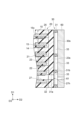
- FIG. 2 is a schematic cross-sectional view showing an enlarged part of the electricity storage module shown in FIG. 1.
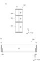
- FIG. 3 is a schematic side view of the electricity storage module shown in FIG. 1.
- FIG. 4(a) is a schematic cross-sectional view taken along line IV-IV in FIG. 3.
- 3(a) shows a state where the frame member 30 is not provided on the sealing body 20, and
- FIG. 3(b) shows a state where the frame member 30 is provided on the sealing body 20. has been done.
- the sealing body 20 is formed with communication holes 27 that communicate with each of the plurality of internal spaces S. As shown in FIGS.
- the communication hole 27 is formed by cutting out a part of the spacer 22, and is formed to pass through the spacer 22 and the welded end portion 23.
- the communication hole 27 has one opening in the internal space S and the other opening 27h in the outer surface 23s of the welded end 23.
- a cell C including one internal space S is formed by a pair of adjacent current collectors 15.
- one communication hole 27 is formed for one cell C.
- the opening 27h of the communication hole 27 is arranged so that its position in the third direction D3 is different for each cell C. It is located.
- the third direction D3 is a direction intersecting the first direction D1 and the second direction D2, and is the width direction of the power storage module 1 along the outer surface 23s.
- the positions of the openings 27h in the third direction D3 are staggered from the cell C on one end side to the cell C on the other end side in the first direction D1. Therefore, here, a plurality of openings 27h whose positions in the third direction D3 are generally the same are provided corresponding to every other cell C, and are arranged along the first direction D1.
- the plurality of openings 27h include a group of openings 28 arranged along the first direction D1 and a first opening 28 at a different position from the openings 28 in the third direction D3. and another group of openings 29 arranged along direction D1.
- the frame member 30 is joined (for example, welded) to the outer surface 23s of the welded end 23.
- the frame member 30 includes a plurality of frame portions 31 surrounding each opening 27h of the plurality of communication holes 27 when viewed from the second direction D2.
- a plurality of frame members 30 are used.
- the plurality of frame members 30 are arranged while being spaced apart from each other along the third direction D3.
- each of the plurality of frame parts 31 of one frame member 30 is provided so as to surround each of one group of openings 28, and each of the plurality of frame parts 31 of another frame member 30 is provided so as to surround each of one group of openings 28. It is set up to surround each of the.
- each of the plurality of frame members 30 is a group of openings 27h different from each other, and is arranged so that the frame portion 31 surrounds a group of openings 28 and 29 arranged in the first direction D1 when viewed from the second direction D2. has been done.
- the frame portion 31 includes a first end surface 31a that is joined (for example, welded) to the outer surface 23s so as to surround each opening 27h of the plurality of communication holes 27 when viewed from the second direction D2, and a first end surface 31a that is joined (for example, welded) to the outer surface 23s so as to surround each opening 27h of the plurality of communication holes 27, and a first end surface 31a that is opposite to the first end surface 31a. It includes a second end surface 31b that is an end surface and is formed so as to surround each opening 27h of the plurality of communication holes 27 when viewed from the second direction D2.
- Each frame member 30 further includes a flange 32 that protrudes from the end of the frame portion 31 on the first end surface 31a side along the outer surface 23s and is joined (for example, welded) to the outer surface 23s.
- the frame portion 31 has a rectangular frame shape. Therefore, the region 33 surrounded by the frame portion 31 when viewed from the second direction D2 has a rectangular shape. The bottom surface of this region 33 is the outer surface 23s of the welded end portion 23 (the outer surface of the sealing body 20).
- the flange 32 extends from a portion of the frame 31 extending along the first direction D1 toward the inside of the region 33 surrounded by the frame 31 along the third direction D3 when viewed from the second direction D2. It stands out. When viewed from the second direction D2, the flange 32 is formed in each region 33 so as to be spaced apart from the opening 27h (that is, does not reach the opening 27h).
- the flange 32 extends from a portion of the frame 31 extending along the first direction D1 toward the outside of the region 33 surrounded by the frame 31 in the third direction D3. It may be provided so as to protrude along. Alternatively, as shown in FIG. 4C, the flange 32 may be provided so as to protrude both inside and outside the region 33 surrounded by the frame portion 31. Furthermore, as shown in FIG. 3(b), in the frame member 30, a portion extending along the third direction D3 of the frame portion 31 toward the inside of the region 33 surrounded by the frame portion 31. Another flange 34 may be provided so as to protrude from the first direction D1. In this case, the flanges 34 are also formed apart from the opening 27h in each region 33 (that is, do not reach the opening 27h) when viewed from the second direction.
- a plurality of frames 31 partition a plurality of (three in the illustrated example) regions 33 arranged along the first direction D1, and each region is divided by a plurality of frames 31 when viewed from the second direction.
- An opening 27h of the communication hole 27 is located within the opening 33.
- the frame member 30 has an end surface 30s (second end surface 31b) on the opposite side to the outer surface 23s of the welded end portion 23 (that is, on the opposite side to the sealing body 20).
- the electrolyte can be introduced into each area 33 through the opening 27h. It becomes possible to inject the electrolytic solution into the internal space S from the communication hole 27 connected to 33.
- the sheet member 40 is joined (for example, bonded) to the end surface 30s to seal the region 33 (that is, the internal space S).
- one sheet member 40 may be provided across the plurality of frame members 30, or one sheet member 40 may be provided for each frame member 30.
- the plurality of frame members 30 are asymmetrical in the first direction D1 by including at least two frame parts 31 having different sizes in the first direction D1. It has a shape.
- the size in the first direction D1 of one of the three frame parts 31 i.e., region 33
- the other two frame parts 31 i.e., region 33).
- a plurality of such asymmetric frame members 30 are arranged in different directions (inverted with respect to the first direction D1). Thereby, the position of the region 33 surrounded by the frame portion 31 in the first direction D1 is made different between the frame members 30 in different orientations. As a result, it is possible to surround the openings 27h of the plurality of communication holes 27 at different positions in the first direction D1 with fewer types of frame members 30.
- the frame member 30 as described above may be formed of a resin having a melting point higher than that of the resin of the sealing body 20. Further, the resin of the sealing body 20 and the resin of the frame member 30 may be resins having the same base resin. As an example, when the sealing body 20 is made of low-density polyethylene, the frame member 30 can be made of high-density polyethylene. Note that the frame member 30 may be formed of a resin having a melting point higher than the melting point of the resin of the sealing body 20, when the sealing body 20 is composed of a plurality of resins. It may also include a case where the frame member 30 is formed of a resin having a melting point higher than that of at least one of the plurality of constituent resins.
- the frame member 30 can be formed of high-density polyethylene.
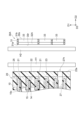
- FIGS. 5 and 6 are schematic cross-sectional views for explaining one step of the method for manufacturing the electricity storage module shown in FIGS. 1 to 4.
- FIG. 5 here, the electrode stack 10, the sealing body 20, and the frame member 30 are separately prepared.
- the sealing body 20 is provided and integrated with the electrode stack 10.
- FIGS. 5 and 6 only a part of the electrode stack 10 and the sealing body 20 are shown.
- the heater H1 is arranged on the outer surface of the sealing body 20 (the outer surface 23s of the welded end portion 23). Moreover, the heater H2 is arranged on the end surface 30r (first end surface 31a) side of the frame member 30 opposite to the end surface 30s.
- the heater H1 is a heater whose temperature is lower than that of the heater H2.
- the sealed body 20 is heated by the heater H1, and a part of the sealed body 20 is melted from the outer surface 23s side.
- the frame member 30 is heated by the heater H2, and a part of the frame member 30 is melted from the end surface 30r side.
- the heater H1 as an infrared heater and the heater H2 as a hot plate heater, only the vicinity of the end surface 30r of the frame member 30 is selectively melted, while the outer part of the sealing body 20 is melted. It is possible to melt from the side surface 23s to a relatively deep position.
- the frame member 30 is sealed. 20 to form a state in which a portion of the sealing body 20 on the outer surface 23s side and a portion of the frame member 30 on the end surface 30r side are compatible with each other. Thereby, the frame member 30 is welded to the sealing body 20.
- the nozzle 60 of the electrolyte injection device is pressed against the end surface 30s of the frame member 30, and the electrolyte is introduced into the region 33 of the frame member 30 from the injection port 61 of the nozzle 60.
- the electrolytic solution is injected into the internal space S of each cell C from the communication hole 27 connected to each region 33 through the opening 27h of the sealing body 20.
- the nozzle 60 is removed from the end surface 30s of the frame member 30, and the sheet member 40 is attached to the end surface 30s so as to seal the region 33. Thereby, the internal space S in which the electrolytic solution is placed is sealed, and the electricity storage module 1 is manufactured.
- the sealing body 20 provided in the electrode stack 10 is provided with the communication hole 27 that communicates with the internal space S that accommodates the electrolyte between the current collectors 15 of the electrodes. It is being
- the sealing body 20 includes a welded end 23 formed by welding a sealing material 21 provided on the peripheral edge 15c of the current collector 15 and an end of a spacer 22 interposed between the sealing material 21. .
- An opening 27h of the communication hole 27 is formed in the outer surface 23s of the welded end portion 23.
- the sealing body 20 is provided with a frame member 30 having a frame portion 31 surrounding the opening 27h of the communication hole 27 on the outer surface 23s of the welded end portion 23.
- the frame member 30 can be used for sealing by pressing the nozzle 60 when injecting the electrolytic solution or when joining another member to the sealing body 20.
- the frame member 30 is configured separately from the sealing body 20, and is joined to the sealing body 20 at a portion of the outer surface 23s surrounding the opening 27h of the communication hole 27. According to this, unlike the case where the frame member 30 is integrally formed with the sealing body 20 by injection molding, defects such as the communication hole 27 being blocked by the resin for injection molding are less likely to occur. Therefore, deterioration in reliability is suppressed.
- the frame member 30 further includes a flange 32 that protrudes from the end of each of the plurality of frame parts 31 on the first end surface 31a side along the outer surface 23s and is joined to the outer surface 23s. Therefore, for example, when pressing the nozzle 60 of an electrolyte injection device against the frame member 30 or when joining another member to the frame member 30, stress applied to the end surface 30s of the frame member 30 is applied to the frame member 30. 31 and the flange 32, the stress applied to the sealing body 20 side is reduced.
- the flange 32 protrudes from the frame 31 toward the inside of the region 33 surrounded by the frame 31 when viewed from the second direction D2. Therefore, it is possible to obtain the above-mentioned effects of having the flange 32 while maintaining the external dimensions of the frame member 30.
- the power storage module 1 includes a plurality of frame members 30 arranged along a third direction D3 that intersects the first direction D1 and the second direction D2 and runs along the outer surface 23s.
- Each of the plurality of frame members 30 is a group of openings 27h different from each other, and is arranged so that the frame portion 31 surrounds a group of openings 28 and 29 arranged along the first direction D1 when viewed from the second direction D2. be done.
- the flange 32 protrudes from the frame portion 31 along the third direction D3. In this way, by using a plurality of frame members 30 and providing the flanges 32 on each of the frame members 30, it is possible to reliably reduce the stress applied to the sealing body 20 side.
- the plurality of frame members 30 include at least two frame portions 31 having different sizes in the first direction D1, so that the frame members 30 have an asymmetric shape in the first direction D1. . Therefore, when the frame member 30 is arranged such that one of the two frame portions 31 having different sizes in the first direction D1 faces toward one side (for example, upper side) in the first direction D1 than the other, , the position of the region 33 surrounded by the frame portion 31 in the first direction D1 can be changed by arranging the frame member 30 in the opposite direction.
- the openings 27h of the plurality of communication holes 27 at different positions in the first direction D1 can be prevented from interfering with the frame portion 31 and the openings 27h. This makes it possible to enclose the area without any problems.
- the sealing body 20 is made of resin
- the frame member 30 is made of a resin having a melting point higher than the melting point of the resin of the sealing body 20.
- the resin for the frame member 30 the same resin as the resin for the sealing body 20 can be used.
- the power storage module according to the present disclosure is not limited to the power storage module 1 described above, and can be modified as desired.
- the method of joining the frame member 30 to the sealing body 20 may be a known method such as bonding using an adhesive. It is also possible to use That is, in the power storage module 1, it is sufficient that the frame member 30 formed separately from the sealing body 20 is joined to the sealing body 20.
- the frame member 30 has the flange 32, but the flange 32 is not essential. Furthermore, the frame member 30 is not limited to having an asymmetrical shape with respect to the first direction D1, and may have a symmetrical shape with respect to the first direction D1. Further, the frame member 30 may include three or more frame portions 31 having different sizes in the first direction D1.
- FIG. 7 is a schematic plan view showing a frame member according to a modification.
- FIG. 8 is a schematic cross-sectional view of the frame member shown in FIG. 7.
- 8(a) is a sectional view taken along line XIIIa-XIIIa in FIG. 7
- FIG. 8(b) is a sectional view taken along line XIIIb-XIIIb in FIG.
- the power storage module 1 can include a frame member 30A shown in FIGS. 7 and 8 instead of the frame member 30 according to the above embodiment.
- the frame member 30A differs from the frame member 30 according to the embodiment described above in that it includes a flange 32A instead of the flange 32, and is the same in other respects.
- the flange 32A has a larger ratio of the length along the height direction (second direction D2) of the frame 31 to the amount of protrusion (thickness) from the frame 31 than the flange 32. , the flange 32 is longer than the flange 32 in the second direction D2), and is formed in an elongated shape in the second direction D2. Such a flange 32A can also be considered as a relatively thick portion of the frame portion 31.
- the flange 32A protrudes toward the inside of the region 33 surrounded by the frame portion 31, but the flange 32A is shown in FIGS. ) may be provided to protrude toward the outside of the region 33 surrounded by the frame 31, or may be provided to protrude toward both the inside and outside of the region 33 .
- the heater H2 is arranged on the end surface 30r (first end surface 31a) side opposite to the end surface 30s of the frame member 30A. Subsequently, the sealed body 20 is heated by the heater H1, and a part of the sealed body 20 is melted from the outer surface 23s side. Further, the frame member 30A is heated by the heater H2, and a part of the frame member 30 is melted from the end surface 30r side.
- the heater H1 as an infrared heater and the heater H2 as a hot plate heater, only the vicinity of the end surface 30r of the frame member 30A is selectively melted, while the outer part of the sealing body 20 is melted. It is possible to melt from the side surface 23s to a relatively deep position.
- the frame member 30A is attached to the sealing body. 20, and push the frame member 30A into the inside of the sealing body 20 from the outer surface 23s side of the sealing body 20.
- the entirety of the flange 32A which is a thick portion of the frame member 30A, is inserted into the welded end 23, thereby making the flange 32A and the welded end 23 compatible. Therefore, after this step, the portion of the frame portion 31 of the frame member 30A other than the flange 32A protrudes from the outer surface 23s of the sealing body 20.
- the following effects can be achieved. That is, when using the frame member 30A, when welding the frame member 30A to the sealing body 20, the tip of the frame member 30A (at least a part of the flange 32A) is attached to the welding end 23 of the sealing body 20. Once inside, the tip of the frame member 30A and the sealing body 20 become compatible. Therefore, it is possible to reliably and airtightly weld the tip of the frame member 30A to the welding end 23.
- the frame member 30A by providing the flange 32A as a thick portion, deformation of the tip portion of the frame member 30A when the tip portion is pushed into the welded end portion 23 is suppressed.
- the side portion along the stacking direction (first direction D1) of the sealing material 21 and the spacer 22 is pushed in crosswise by the plurality of sealing materials 21 and spacers 22, so that a relatively large force is applied to the side portion of the frame member 30A. Therefore, it is effective to form a flange 32 as a thick wall portion in the modified portion to reinforce it.
- the electricity storage module includes [1] "an electrode stack including a current collector and an active material layer formed on the current collector, and including a plurality of electrodes stacked along a first direction; a sealing body provided on the electrode stack so as to form an internal space between the adjacent current collectors and to seal the internal space; an electrolytic solution accommodated in the internal space; a frame member configured separately from the sealing body and joined to the sealing body, and the sealing body includes a plurality of frame-shaped frames provided at the peripheral edge of each of the plurality of current collectors.
- a plurality of spacers that are interposed between the sealing materials adjacent in the first direction and forming the internal space between the current collectors together with the plurality of sealing materials; and the plurality of sealing materials. and a welded end portion formed by welding ends of the plurality of spacers opposite to the internal space, and a welded end portion that communicates with each of the plurality of internal spaces, and a welded end portion of the welded end portion on the opposite side to the internal space.
- the frame member including a plurality of frame portions surrounding the openings of each of the plurality of communication holes when viewed from a second direction intersecting the outer surface;
- Each of the plurality of frame portions has a first end surface joined to the outer surface so as to surround the opening of each of the plurality of communication holes when viewed from the second direction, and an end surface opposite to the first end surface. and a second end surface formed so as to surround the opening of each of the plurality of communication holes when viewed from the second direction.
- the power storage module according to the present disclosure includes [2] "The frame member protrudes from an end on the first end surface side of each of the plurality of frame parts along the outer surface and is joined to the outer surface.
- the power storage module according to [1] above may further include a flange.
- the power storage module according to the present disclosure includes [3] "The power storage module according to [2] above, wherein the flange protrudes from the frame toward the inside of a region surrounded by the frame when viewed from the second direction. It may also be a module.
- the power storage module according to the present disclosure includes [4] "a plurality of frame members arranged along a third direction that intersects the first direction and the second direction and is a direction along the outer surface," Each of the plurality of frame members is a group of different openings, and is arranged so that the frame portion surrounds a group of openings arranged along the first direction when viewed from the second direction,
- the flange may be the electricity storage module according to [2] or [3] above, in which the flange protrudes from the frame along the third direction.
- the electricity storage module according to the present disclosure is provided with the following features: [5] "The plurality of frame members have an asymmetric shape in the first direction by including at least two frame parts having different sizes in the first direction.
- the power storage module according to [4] above may include the frame member.
- the electricity storage module according to the present disclosure includes [6] "The sealing body is made of resin, the frame member is made of the same base resin as the resin of the sealing body, and the melting point of the resin of the sealing body is The electricity storage module according to any one of [1] to [5] above, which is made of a resin having a melting point higher than the above.
- SYMBOLS 1 Energy storage module, 10... Electrode laminate, 11... Bipolar electrode (electrode), 12... Positive electrode terminal electrode (electrode), 13... Negative electrode terminal electrode (electrode), 15... Current collector, 16... Positive electrode active material layer ( active material layer), 17... negative electrode active material layer (active material layer), 20... sealing body, 21... sealing material, 22... spacer, 23... welding end, 23s... outer surface, 27... communicating hole, 27h... Opening, 30, 30A... Frame member, 30s... End surface, 31... Frame portion, 31a... First end surface, 31b... Second end surface, 32, 32A... Flange, 33... Region, D1... First direction, D2... Second Direction, D3...Third direction, S...Internal space.
Landscapes
- Chemical & Material Sciences (AREA)
- Chemical Kinetics & Catalysis (AREA)
- Electrochemistry (AREA)
- General Chemical & Material Sciences (AREA)
- Engineering & Computer Science (AREA)
- Power Engineering (AREA)
- Manufacturing & Machinery (AREA)
- Microelectronics & Electronic Packaging (AREA)
- Sealing Battery Cases Or Jackets (AREA)
Abstract
電極積層体と、前記電極積層体に設けられた封止体と、前記封止体と別体に構成されて前記封止体に接合された枠部材と、を備え、前記封止体は、シール材及びスペーサの端部が溶着されて形成された溶着端部と、前記溶着端部の外側面に開口を有する連通孔と、を含み、前記枠部材は、前記連通孔の前記開口を囲む枠部を含み、前記枠部は、前記開口を囲むように前記外側面に接合される第1端面と、前記第1端面と反対側の端面であって、前記開口を囲むように形成される第2端面と、を有する、蓄電モジュール。
Description
本開示は、蓄電モジュールに関する。
特許文献1には、蓄電モジュールが記載されている。この蓄電モジュールは、セパレータを介して積層された複数の電極を含む電極積層体と、電極積層体を取り囲むように配置された封止体と、を有している。封止体は、電極板の周縁部に設けられた第1樹脂部と、複数の第1樹脂部を取り囲むように複数の第1樹脂部の外側に設けられた第2樹脂部と、を含む。封止体には、電極間に形成された互いに異なる内部空間に連通する複数の連通孔が設けられている。連通孔は、例えば内部空間に電解液を供給するために用いられる。封止体を構成する4つの壁部のうちの1つの壁部には、複数の連通孔が同数ずつ設けられた複数の連通孔領域が形成されている。この蓄電モジュールにおいて、電解液の供給装置のノズルの先端面を、パッキンを介して封止体の連通孔領域に押し付けた状態において、内部空間への電解液の供給が行われる。このとき、パッキンは、複数の連通孔のそれぞれを囲むように連通孔領域に設けられた複数の突条部において、強く圧縮される。
特許文献2には、蓄電モジュールが記載されている。この蓄電モジュールは、セパレータを介して積層された複数の電極を含む電極積層体と、電極積層体を取り囲むように配置された枠体と、枠体に取り付けられた圧力調整弁と、を備えている。枠体は、電極板の周縁部に設けられた第1封止部と、第1封止部の外側に設けられた第2封止部と、を含む。枠体を構成する1つの壁部には、圧力調整弁を取り付けるための複数の取付領域が設けられている。各取付領域において、枠体は、電極間に形成された内部空間に連通された連通孔が設けられている。連通孔は、例えば内部空間に電解液を供給するために用いられる。この蓄電モジュールでは、当該取付領域に圧力調整弁が取り付けられることにより、連通孔が封止され得る。枠体には、取付領域において枠状の突起が設けられており、圧力調整弁との熱溶着による接合に用いられる。
特許文献1及び特許文献2では、射出成形によって、第2樹脂部や第2封止部と共に枠状の突条部や突起を形成している。具体的な一例としては、第1封止部が設けられた電極板を積層して構成される積層体を、射出成型用の型内に配置して樹脂を注入するインサート成形により、第2封止部と共に枠状の突起を形成する。このとき、型内に注入された樹脂が、第1封止部の連通孔の開口を含む外側面の全体に流動する。この結果、当該樹脂により連通孔が塞がるといった不良が発生し、信頼性の低下につながるおそれがある。
本開示は、信頼性の低下を抑制可能な蓄電モジュールを提供することを目的とする。
本開示に係る蓄電モジュールは、集電体と集電体に形成された活物質層とを含み、第1方向に沿って積層された複数の電極を含む電極積層体と、隣り合う集電体の間に内部空間を形成すると共に、当該内部空間を封止するように電極積層体に設けられた封止体と、内部空間に収容された電解液と、封止体と別体に構成されて封止体に接合された枠部材と、を備え、封止体は、複数の集電体のそれぞれの周縁部に設けられた枠状の複数のシール材と、第1方向に隣り合うシール材の間に介在され、複数のシール材と共に集電体の間に内部空間を形成する複数のスペーサと、複数のシール材及び複数のスペーサの内部空間と反対側の端部が溶着されて形成された溶着端部と、複数の内部空間のそれぞれに連通し、溶着端部の内部空間と反対側の外側面に開口を有する連通孔と、を含み、枠部材は、外側面に交差する第2方向からみて複数の連通孔のそれぞれの開口を囲む複数の枠部を含み、複数の枠部のそれぞれは、第2方向からみて複数の連通孔のそれぞれの開口を囲むように外側面に接合される第1端面と、第1端面と反対側の端面であって、第2方向からみて複数の連通孔のそれぞれの開口を囲むように形成される第2端面と、を有する。
この蓄電モジュールでは、電極積層体に設けられた封止体には、電極の集電体間の電解液を収容する内部空間に連通する連通孔が設けられている。封止体は、集電体の周縁部に設けられたシール材と、シール材間に介在されたスペーサの端部とが溶着されて形成された溶着端部を含む。この溶着端部の外側面には、上記の連通孔の開口が形成されている。そして、封止体には、溶着端部の外側面における連通孔の開口を囲む枠部を有する枠部材が設けられている。したがって、例えば、電解液の注液のときのノズルの押し当てによる封止や、封止体に別部材を接合する際に、当該枠部材を利用することが可能である。そして、この蓄電モジュールでは、当該枠部材が封止体とは別体に構成されて、外側面の連通孔の開口を囲う部分において封止体に接合されている。これによれば、射出成形により枠部材を封止体と一体的に形成する場合と異なり、射出成形のための樹脂によって連通孔が塞がるといった不良が発生しにくい。よって、信頼性の低下が抑制される。
本開示に係る蓄電モジュールでは、枠部材は、複数の枠部のそれぞれにおける第1端面側の端部から外側面に沿って突出すると共に外側面に接合されるフランジをさらに含んでもよい。この構成によれば、例えば、電解液の注液装置のノズル等を枠部材に押し当てる場合や、別部材を枠部材に接合する場合に、枠部材の端面に加えられる応力が枠部とフランジとに分散されることにより、封止体側にかかる応力が低減される。したがって、枠部材がフランジを有していない場合と比較して、封止体側の構造の損傷を抑制しつつ、枠部材の端面に加える面圧を大きくして封止や接合の不良を抑制することが可能となる。
本開示に係る蓄電モジュールでは、フランジは、第2方向からみて枠部で囲われる領域の内側に向けて枠部から突出していてもよい。この場合、枠部材の外形寸法を維持したまま、フランジを有することの上記効果を得ることが可能となる。
本開示に係る蓄電モジュールでは、第1方向及び第2方向に交差すると共に外側面に沿う方向である第3方向に沿って配列された複数の枠部材を備え、複数の枠部材のそれぞれは、互いに異なる一群の開口であって、第2方向からみて第1方向に沿って配列された一群の開口を枠部によって囲うように配置され、フランジは、第3方向に沿って枠部から突出していてもよい。このように、複数の枠部材を用いて、各枠部材にフランジを設けることにより、封止体側にかかる応力を確実に低減可能である。
本開示に係る蓄電モジュールでは、複数の枠部材は、第1方向についての大きさが異なる少なくとも2つの枠部を含むことにより、第1方向について非対称な形状を有する枠部材を含んでもよい。この場合、第1方向についての大きさが異なる2つの枠部のうちの一方が他方よりも第1方向の一方側(例えば上側)に向くように枠部材が配置される場合と、その逆の向きに枠部材が配置される場合とで、第1方向における枠部に囲われる領域の位置を変化させることができる。よって、第1方向の位置が異なる複数の連通孔の開口を、より少ない種類の枠部材によって(すなわち、部品点数を削減しつつ)、干渉することなく囲うことが可能となる。
本開示に係る蓄電モジュールでは、封止体は、樹脂からなり、枠部材は、封止体の樹脂と同じ主剤の樹脂であって、封止体の樹脂の融点よりも高い融点を有する樹脂からなってもよい。この場合、例えば溶着により枠部材を封止体に接合した場合に、収縮による枠部材の変形が抑制される。
本開示によれば、信頼性を向上可能な蓄電モジュールを提供できる。
以下、図面を参照して一実施形態について説明する。なお、図面の説明において、同一又は同等の要素には同一の符号を付し、重複する説明を省略する場合がある。第1方向D1を示す座標軸、第2方向D2を示す座標軸、及び、第3方向D3を示す座標軸によって規定される直交座標系を示す。
図1は、本実施形態に係る蓄電モジュールの模式的な断面図である。図1に示される蓄電モジュール1は、例えば、フォークリフト、ハイブリッド自動車、電気自動車等の各種車両のバッテリに用いられる蓄電モジュールである。蓄電モジュール1は、例えばニッケル水素二次電池又はリチウムイオン二次電池等の二次電池である。蓄電モジュール1は、電気二重層キャパシタであってもよいし、全固体電池であってもよい。ここでは、蓄電モジュール1がリチウムイオン二次電池である場合を例示する。
蓄電モジュール1は、電極積層体10と、封止体20と、枠部材30と、シート部材40と、を備えている。電極積層体10は、第1方向D1に沿って積層された複数の電極を含む。第1方向D1は、電極の積層方向であって、蓄電モジュール1の高さ方向である。複数の電極は、複数のバイポーラ電極11と、正極終端電極12と、負極終端電極13と、を含む。互いに隣り合う電極の間には、セパレータ14が介在されている。電極積層体10は、正極終端電極12と負極終端電極13との間に、複数のバイポーラ電極11を積層することにより形成されている。
バイポーラ電極11は、集電体15と、正極活物質層16と、負極活物質層17と、を有している。集電体15は、例えば矩形シート状を呈している。集電体15は、一方の表面である第1主面15a、及び第1主面15aとは反対側の他方の表面である第2主面15bを含んでいる。すなわち、集電体15は、積層方向Dにおいて互いに逆向きの第1主面15aと第2主面15bとを有している。正極活物質層16は、集電体15の第1主面15aに設けられている。負極活物質層17は、集電体15の第2主面15bに設けられている。複数のバイポーラ電極11は、一のバイポーラ電極11の正極活物質層16と別のバイポーラ電極11の負極活物質層17とが対向するように積層されている。ここでは、集電体15の第1主面15aは、第1方向D1の一方を向く面であり、集電体15の第2主面15bは、第1方向D1の他方を向く面である。
正極活物質層16及び負極活物質層17は、第1方向D1からみて矩形状である。負極活物質層17は、第1方向D1から見て正極活物質層16よりも一回り大きい。つまり、第1方向D1から見た平面視において、正極活物質層16の形成領域の全体が負極活物質層17の形成領域内に位置している。
正極終端電極12は、集電体15と、集電体15の第1主面15aに設けられた正極活物質層16と、を有している。正極終端電極12は、集電体15の第2主面15bにおいて正極活物質層16及び負極活物質層17を有していない。つまり、正極終端電極12の集電体15の第2主面15bには、活物質層が設けられていない。正極終端電極12の集電体15の第2主面15bは、蓄電モジュール1の正極端子面となっている。正極終端電極12は、電極積層体10の第1方向D1の一方側の端部においてバイポーラ電極11に積層されている。正極終端電極12は、その正極活物質層16がバイポーラ電極11の負極活物質層17に対向するようにバイポーラ電極11に積層されている。
負極終端電極13は、集電体15と、集電体15の第2主面15bに設けられた負極活物質層17と、を有している。負極終端電極13は、集電体15の第1主面15aにおいて正極活物質層16及び負極活物質層17を有していない。つまり、負極終端電極13の集電体15の第1主面15aには、活物質層が設けられていない。負極終端電極13の集電体15の第1主面15aは、蓄電モジュール1の負極端子面となっている。負極終端電極13は、電極積層体10の第1方向D1の他方側の端部においてバイポーラ電極11に積層されている。つまり、負極終端電極13は、複数のバイポーラ電極11に対して、正極終端電極12とは反対側に配置されている。負極終端電極13は、その負極活物質層17がバイポーラ電極11の正極活物質層16に対向するようにバイポーラ電極11に積層されている。
セパレータ14は、第1方向D1において隣り合うバイポーラ電極11の間、正極終端電極12とバイポーラ電極11の間、及び、負極終端電極13とバイポーラ電極11との間に、それぞれ配置されている。セパレータ14は、正極活物質層16と負極活物質層17との間に介在している。セパレータ14は、正極活物質層16と負極活物質層17とを隔離することで、隣り合う電極の接触による短絡を防止しつつ、リチウムイオンのような電荷担体を通過させる。
集電体15は、リチウムイオン二次電池の放電又は充電の間、正極活物質層16及び負極活物質層17に電流を流し続けるための化学的に不活性な電気伝導体である。集電体15の材料は、例えば、金属材料、導電性樹脂材料又は導電性無機材料等である。導電性樹脂材料としては、例えば、導電性高分子材料又は非導電性高分子材料に必要に応じて導電性フィラーが添加された樹脂等が挙げられる。集電体15は、複数の層を備えていてもよい。この場合、集電体15の各層は、上記の金属材料又は導電性樹脂材料を含んでいてもよい。
集電体15の表面には、被覆層が形成されていてもよい。当該被覆層は、例えばメッキ処理又はスプレーコート等の公知の方法によって形成されていてもよい。集電体15は、例えば、板状、箔状(例えば金属箔)、フィルム状又はメッシュ状等を呈していてもよい。金属箔としては、例えば、アルミニウム箔、銅箔、ニッケル箔、チタン箔又はステンレス鋼箔等が挙げられる。集電体15は、上記の金属の合金箔や、複数枚の上記金属箔を貼り合わせ等により一体化させたものであってもよい。集電体15が箔状を呈している場合、集電体15の厚さは、例えば、1μm~100μmであってもよい。なお、例えば、バイポーラ電極11、正極終端電極12、負極終端電極13のそれぞれの集電体15のうち、いくつかの集電体15は、その厚さが100μm以上であってもよい。この場合、電極積層体10の構造安定性が高まる。
正極活物質層16は、リチウムイオンのような電荷担体を吸蔵及び放出し得る正極活物質を含んでいる。正極活物質としては、例えば、層状岩塩構造を有するリチウム複合金属酸化物、スピネル構造を有する金属酸化物、ポリアニオン系化合物等が挙げられる。正極活物質は、リチウムイオン二次電池に使用可能なものであればよい。正極活物質層16は、複数の正極活物質を含んでいてもよい。本実施形態では、正極活物質層16は、複合酸化物としてのオリビン型リン酸鉄リチウム(LiFePO4)を含んでいる。
負極活物質層17は、リチウムイオンのような電荷担体を吸蔵及び放出し得る負極活物質を含んでいる。負極活物質は、単体、合金又は化合物のいずれであってもよい。負極活物質としては、例えば、Li、炭素、金属化合物等が挙げられる。負極活物質は、リチウムと合金化可能な元素もしくはその化合物等であってもよい。炭素としては、例えば、天然黒鉛、人造黒鉛、ハードカーボン(難黒鉛化性炭素)又はソフトカーボン(易黒鉛化性炭素)等が挙げられる。人造黒鉛としては、例えば、高配向性グラファイト、メソカーボンマイクロビーズ等が挙げられる。リチウムと合金化可能な元素としては、シリコン(ケイ素)又はスズ等が挙げられる。本実施形態では、負極活物質層17は、炭素系材料としての黒鉛を含んでいる。
正極活物質層16及び負極活物質層17のそれぞれ(以下、単に「活物質層」という場合がある)は、必要に応じて電気伝導性を高めるための導電助剤、結着剤、電解質(ポリマーマトリクス、イオン伝導性ポリマー、電解液等)、イオン伝導性を高めるための電解質支持塩(リチウム塩)等をさらに含み得る。導電助剤は、各電極(バイポーラ電極11、正極終端電極12、負極終端電極13)の導電性を高めるために添加される。導電助剤は、例えばアセチレンブラック、カーボンブラック又はグラファイト等である。
結着剤としては、ポリフッ化ビニリデン、ポリテトラフルオロエチレン、フッ素ゴム等の含フッ素樹脂、ポリプロピレン、ポリエチレン等の熱可塑性樹脂、ポリイミド、ポリアミドイミド等のイミド系樹脂、アルコキシシリル基含有樹脂、アクリル酸又はメタクリル酸等のアクリル系樹脂、スチレン-ブタジエンゴム(SBR)、カルボキシメチルセルロース、アルギン酸ナトリウム、アルギン酸アンモニウム等のアルギン酸塩、水溶性セルロースエステル架橋体、デンプン-アクリル酸グラフト重合体等が挙げられる。これらの結着剤は、単独で又は複数で用いられ得る。溶媒には、例えば、水、N-メチル-2-ピロリドン(NMP)等が用いられる。
セパレータ14は、例えば、電解質を吸収保持するポリマーを含む多孔性シート又は不織布であってもよい。セパレータ14の材料としては、例えば、ポリプロピレン、ポリエチレン、ポリオレフィン、ポリエステル等が挙げられる。セパレータ14は、単層構造又は多層構造を有していてもよい。多層構造は、例えば、接着層又は耐熱層としてのセラミック層等を有していてもよい。セパレータ14には、電解質が含浸されていてもよい。セパレータ14は、高分子電解質又は無機型電解質等の電解質によって構成されていてもよい。セパレータ14に含浸される電解質としては、例えば、非水溶媒と非水溶媒に溶解された電解質塩とを含む液体電解質(電解液)、又はポリマーマトリクス中に保持された電解質を含む高分子ゲル電解質等が挙げられる。
セパレータ14に電解液が含浸される場合、その電解質塩としては、LiClO4、LiAsF6、LiPF6、LiBF4、LiCF3SO3、LiN(FSO2)2、LiN(CF3SO2)2等の公知のリチウム塩が用いられていてもよい。また、非水溶媒としては、環状カーボネート類、環状エステル類、鎖状カーボネート類、鎖状エステル類、エーテル類等の公知の溶媒が用いられていてもよい。なお、二種以上のこれらの公知の溶媒材料が組合せて用いられていてもよい。
封止体20は、電極積層体10を取り囲むように、電極積層体10の周縁部に枠状に形成されている。封止体20は、集電体15それぞれの周縁部15cにおいて、集電体15の第1主面15a及び第2主面15bのそれぞれに接合され得る。封止体20は、第1方向D1に隣り合う集電体15の間に内部空間Sを形成すると共に、当該内部空間Sのそれぞれを封止するためのものである。それぞれの内部空間Sには、電解液(不図示)が収容されている。すなわち、封止体20は、第1方向D1に隣り合う集電体15と共に電解液を収容する内部空間Sを画成する。封止体20は、電解液の外部への透過を防止している。
封止体20は、電極積層体10の外部から内部空間Sへの水分やガス等の侵入を抑制すると共に、電極積層体10に含まれる電解質が外部に漏出することを抑制している。セパレータ14の縁部は、封止体20に接合されている。封止体20は、絶縁材料を含んでいる。封止体20の材料としては、例えば、ポリプロピレン、ポリエチレン、ポリスチレン、ABS樹脂、酸変性ポリプロピレン、酸変性ポリエチレン、アクリロニトリルスチレン樹脂等の種々の樹脂材料が挙げられる。
封止体20は、複数のシール材21、複数のスペーサ22、及び、溶着端部23を含む。シール材21は、集電体15のそれぞれに設けられている。したがって、シール材21は、第1方向D1に沿って互いに積層されている。シール材21は、枠状であり、集電体15の周縁部15cに設けられている。つまり、シール材21は、集電体15の第1主面15aから端面を経て第2主面15bに至るように設けられ、周縁部15cを被覆している。シール材21は、集電体15の第1主面15a及び第2主面15bのうちの少なくとも一方に溶着され得る。
スペーサ22は、第1方向D1に隣り合うシール材21の間に介在するように配置されている。これにより、スペーサ22は、第1方向D1に隣り合うシール材21の間、すなわち、第1方向D1に隣り合う集電体15の間のスペースを保持している。スペーサ22は、内周端面と外周端面とを有する枠状を呈しており、第1方向D1からみて集電体15の周縁部15c上に配置されている。ここでは、セパレータ14の端部は、シール材21とスペーサ22との間に挟まれて固定されている。セパレータ14の端部は、シール材21及びスペーサ22の少なくとも一方に溶着され得る。
溶着端部23は、複数のシール材21と複数のスペーサ22の内部空間Sと反対側の端部が溶着されて一体化されることにより形成されている。より具体的には、第1方向D1からみて集電体15よりも外側に位置する複数のシール材21及び複数のスペーサ22の部位同士が溶着されて溶着端部23が形成されている。溶着端部23は、第1方向D1から見て、電極積層体10を取り囲むように枠状を呈している。溶着端部23の内部空間Sと反対側の外側面23sは、第1方向D1に沿って延びており、封止体20の外側面を構成している。
なお、封止体20は、肉盛り部25を有している。肉盛り部25は、正極終端電極12及び負極終端電極13の集電体15に設けられたシール材21の第1方向D1の外側の表面上に配置されている。肉盛り部25は、シール材21に接合されている。第1方向D1からみて集電体15よりも外側に位置する肉盛り部25の端部は、シール材21の端部に溶着され、溶着端部23の一部を構成している。封止体20は、第1方向D1からみたときの外形が多角形状であり、当該多角形のそれぞれの辺を含む。例えば、第1方向D1からみたときの封止体20の外形が四角形である場合、封止体20は、4つの辺を含む。後述する連通孔27は、封止体20の当該複数の辺のうちの1つの辺に設けられる。そして、ここでは、肉盛り部25は、当該連通孔27が設けられた辺のみに設けられている。
また、正極終端電極12の集電体15の第1主面15a、及び、負極終端電極13の集電体15の第2主面15bの封止体20から露出された部分には、蓄電モジュール1から電流を取り出すための端子として機能する導電部材50が配置されて電気的に接続されている。導電部材50は、複数の蓄電モジュール1を電気的に接続するために利用され得る。また、導電部材50は、電極積層体10に対して拘束荷重を付加するために拘束部材としても利用され得る。さらに、導電部材50には、冷却流路が形成されていてもよい。導電部材50に形成された冷却流路に冷却媒体を流通させることによって、電極積層体10を冷却することができる。
枠部材30は、封止体20とは別体に構成されて封止体20に接合されている。ここでは、枠部材30は、封止体20の外側面である溶着端部23の外側面23sに接合(例えば溶着)されている。枠部材30は、第1方向D1について、一方の肉盛り部25(正極終端電極12側の肉盛り部25)から他方の肉盛り部25(負極終端電極13側の肉盛り部25)にわたって延在している。したがって、第1方向D1における枠部材30の外縁は、肉盛り部25上に位置し、一例として肉盛り部25の外縁と一致している。シート部材40は、枠部材30における封止体20と反対側の端面30sに接合されている(張り付けられている)。シート部材40は、例えば、ラミネートフィルムである。引き続いて、枠部材30の詳細について説明する。
図2は、図1に示された蓄電モジュールの一部を拡大して示す概略断面図である。図3は、図1に示された蓄電モジュールの模式的な側面図である。図4の(a)は、図3のIV-IV線に沿っての概略断面図である。図3の(a)では、封止体20に枠部材30が設けられていない状態が示され、図3の(b)では、封止体20に枠部材30が設けられている状態が示されている。図2,3及び図4の(a)に示されるように、封止体20には、複数の内部空間Sのそれぞれに連通する連通孔27が形成されている。
一例として、連通孔27は、スペーサ22の一部を切り欠くことで形成され、スペーサ22及び溶着端部23を貫通して形成されている。連通孔27は、内部空間Sに一方の開口を有すると共に、溶着端部23の外側面23sに他方の開口27hを有している。蓄電モジュール1では、隣り合う一対の集電体15によって、1つの内部空間Sを含むセルCが形成されている。ここでは、1つのセルCに対して1つの連通孔27が形成されている。外側面23sに交差(直交)する第2方向D2からみたとき(図3の(a)参照)、連通孔27の開口27hは、その第3方向D3についての位置がセルCごとに異なるように配置されている。第3方向D3は、第1方向D1及び第2方向D2に交差する方向であって、外側面23sに沿う蓄電モジュール1の幅方向である。
一例として、第3方向D3における開口27hの位置は、第1方向D1の一端側のセルCから他端側のセルCにかけて互い違いにされている。したがって、ここでは、第3方向D3の位置が概ね同一の複数の開口27hが、1つおきのセルCに対応して設けられ、第1方向D1に沿って配列されている。換言すれば、ここでは、複数の開口27hは、第2方向D2からみて、第1方向D1に沿って配列された一群の開口28と、第3方向D3について開口28とは異なる位置において第1方向D1に沿って配列された別の一群の開口29とを含む。
枠部材30は、溶着端部23の外側面23sに接合(例えば溶着)されている。枠部材30は、第2方向D2からみて、複数の連通孔27のそれぞれの開口27hを囲む複数の枠部31を含む。ここでは、複数の枠部材30が用いられている。複数の枠部材30は、第3方向D3に沿って互いに離間しつつ配列されている。ここでは、1つの枠部材30の複数の枠部31のそれぞれが一群の開口28のそれぞれを囲うように設けられ、別の枠部材30の複数の枠部31のそれぞれが別の一群の開口29のそれぞれを囲うように設けられている。すなわち、複数の枠部材30のそれぞれは、互いに異なる一群の開口27hであって、第2方向D2からみて第1方向D1に配列された一群の開口28,29を枠部31によって囲うように配置されている。
枠部31は、第2方向D2からみて複数の連通孔27のそれぞれの開口27hを囲むように外側面23sに接合(例えば溶着)される第1端面31aと、第1端面31aと反対側の端面であって、第2方向D2からみて複数の連通孔27のそれぞれの開口27hを囲むように形成される第2端面31bと、を含む。それぞれの枠部材30は、枠部31の第1端面31a側の端部から外側面23sに沿って突出すると共に、外側面23sに接合(例えば溶着)されるフランジ32をさらに含む。ここでは、枠部31は、矩形枠状を呈している。したがって、第2方向D2からみて枠部31に囲われる領域33は、矩形状である。この領域33の底面は溶着端部23の外側面23s(封止体20の外側面)とされている。この例では、フランジ32は、第2方向D2からみて、枠部31で囲われる領域33の内側に向けて、枠部31の第1方向D1に沿って延びる部分から第3方向D3に沿って突出している。第2方向D2からみて、フランジ32は、領域33のそれぞれにおいて、開口27hから離間するように形成されている(すなわち、開口27h至らない)。
ただし、図4の(b)に示されるように、フランジ32は、枠部31で囲われる領域33の外側に向けて、枠部31の第1方向D1に沿って延びる部分から第3方向D3に沿って突出するように設けられてもよい。或いは、図4の(c)に示されるように、フランジ32は、枠部31で囲われる領域33の内側及び外側の両方に向けて突出するように設けられてもよい。さらには、図3の(b)に示されるように、枠部材30にあっては、枠部31で囲われる領域33の内側に向けて、枠部31の第3方向D3に沿って延びる部分から第1方向D1に沿って突出するように別のフランジ34が設けられていてもよい。この場合、フランジ34についても、第2方向からみて、それぞれの領域33において開口27hより離間して形成される(すなわち、開口27h至らない)。
再び図2~4を参照する。1つの枠部材30では、複数の枠部31によって、第1方向D1に沿って配列された複数(図示の例では3つ)の領域33が区画されており、第2方向からみてそれぞれの領域33内に連通孔27の開口27hが位置させられている。また、枠部材30は、溶着端部23の外側面23sと反対側(すなわち封止体20と反対側)の端面30s(第2端面31b)を有する。したがって、後述するように、電解液の注液装置のノズルをこの端面30sに密着させた状態で当該ノズルからそれぞれの領域33内に電解液を導入することにより、開口27hを介してそれぞれの領域33に繋がる連通孔27から、内部空間Sに電解液を注液することが可能となる。
なお、シート部材40は、端面30sに接合(例えば接着)されて領域33(すなわち内部空間S)を封止している。蓄電モジュール1においては、複数の枠部材30にわたって1つのシート部材40が設けられていてもよいし、1つの枠部材30ごとに1つのシート部材40が設けられていてもよい。
ここで、図3の(b)に示されるように、複数の枠部材30は、第1方向D1についての大きさが異なる少なくとも2つの枠部31を含むことにより、第1方向D1について非対称な形状を有する。ここでは、1つの枠部材30について、3つの枠部31のうちの1つの枠部31(すなわち領域33)の第1方向D1についての大きさが、他の2つの枠部31(すなわち領域33)の第1方向D1についての大きさよりも大きくされている。
そして、このような非対称な複数の枠部材30が、向きを違えて(第1方向D1について反転されて)配置されている。これにより、第1方向D1における枠部31に囲われる領域33の位置が、異なる向きの枠部材30の間で異ならせられている。この結果、第1方向D1の位置が異なる複数の連通孔27の開口27hを、より少ない種類の枠部材30によって囲うことが可能とされている。
以上のような枠部材30は、封止体20の樹脂の融点よりも高い融点を有する樹脂により形成され得る。また、封止体20の樹脂と枠部材30の樹脂とは、互いに主剤が同じ樹脂を用いることができる。一例として、封止体20が低密度ポリエチレンから形成される場合、高密度ポリエチレンにより枠部材30を形成することができる。なお、枠部材30が封止体20の樹脂の融点よりも高い融点を有する樹脂により形成され得るとは、封止体20が複数の樹脂により構成されている場合には、封止体20を構成する複数の樹脂のうちの少なくとも1つの樹脂の融点よりも高い融点を有する樹脂により枠部材30が形成される場合も含み得る。一例として、封止体20のうち、シール材21を低密度ポリエチレンで形成し、スペーサ22及び肉盛り部25を高密度ポリエチレンで形成する場合、高密度ポリエチレンにより枠部材30を形成することができる。
引き続いて、蓄電モジュール1の製造方法について説明する。図5及び図6は、図1~4に示された蓄電モジュールの製造方法の一工程を説明するための概略断面図である。図5に示されるように、ここでは、電極積層体10及び封止体20と、枠部材30とを別途に用意する。封止体20は電極積層体10に設けられて一体化されている。なお、図5,6では、電極積層体10及び封止体20の一部のみを示している。
続いて、封止体20の外側面(溶着端部23の外側面23s)側にヒータH1を配置する。また、枠部材30の端面30sと反対側の端面30r(第1端面31a)側にヒータH2を配置する。ヒータH1は、ヒータH2よりも低温のヒータである。続いて、ヒータH1により封止体20を加熱し、外側面23s側から封止体20の一部を溶融させる。また、ヒータH2により枠部材30を加熱し、端面30r側から枠部材30の一部を溶融させる。このとき、一例として、ヒータH1を赤外線ヒータとし、ヒータH2を熱板ヒータとすることにより、枠部材30については端面30r近傍のみを選択的に溶融させる一方で、封止体20については、外側面23sから相対的に深い位置まで溶融させることができる。
続いて、図6に示されるように、封止体20の外側面23s側の一部と枠部材30の端面30r側の一部とが溶融している状態において、枠部材30を封止体20に押し付け、封止体20の外側面23s側の一部と枠部材30の端面30r側の一部とが相溶した状態を形成する。これにより、封止体20に対して枠部材30が溶着される。
続いて、電解液の注液装置のノズル60を枠部材30の端面30sに押し当てて密着させ、ノズル60の注液口61から枠部材30の領域33内に電解液を導入する。これにより、封止体20の開口27hを介してそれぞれの領域33に繋がる連通孔27から、各セルCの内部空間Sに電解液が注液される。その後、枠部材30の端面30sからノズル60を取り外し、領域33を封止するように端面30sにシート部材40を張り付ける。これにより、電解液が配置された内部空間Sが封止され、蓄電モジュール1が製造される。
以上説明したように、蓄電モジュール1では、電極積層体10に設けられた封止体20には、電極の集電体15間の電解液を収容する内部空間Sに連通する連通孔27が設けられている。封止体20は、集電体15の周縁部15cに設けられたシール材21と、シール材21間に介在されたスペーサ22の端部とが溶着されて形成された溶着端部23を含む。この溶着端部23の外側面23sには、連通孔27の開口27hが形成されている。そして、封止体20には、溶着端部23の外側面23sにおける連通孔27の開口27hを囲む枠部31を有する枠部材30が設けられている。
したがって、例えば、電解液の注液のときのノズル60の押し当てによる封止や、封止体20に別部材を接合する際に、枠部材30を利用することが可能である。そして、この蓄電モジュール1では、枠部材30が封止体20とは別体に構成され、外側面23sの連通孔27の開口27hを囲う部分において、封止体20に接合されている。これによれば、射出成形により枠部材30を封止体20と一体的に形成する場合と異なり、射出成形のための樹脂によって連通孔27が塞がるといった不良が発生しにくい。よって、信頼性の低下が抑制される。
また、蓄電モジュール1では、枠部材30は、複数の枠部31のそれぞれにおける第1端面31a側の端部から外側面23sに沿って突出すると共に外側面23sに接合されるフランジ32をさらに含む。このため、例えば、電解液の注液装置のノズル60等を枠部材30に押し当てる場合や、別部材を枠部材30に接合する場合に、枠部材30の端面30sに加えられる応力が枠部31とフランジ32とに分散されることにより、封止体20側にかかる応力が低減される。したがって、枠部材30がフランジ32を有していない場合と比較して、封止体20側の構造の損傷を抑制しつつ、枠部材30の端面30sに加える面圧を大きくして封止や接合の不良を抑制することが可能となる。
また、蓄電モジュール1では、フランジ32は、第2方向D2からみて枠部31で囲われる領域33の内側に向けて枠部31から突出している。このため、枠部材30の外形寸法を維持したまま、フランジ32を有することの上記効果を得ることが可能となる。
また、蓄電モジュール1では、第1方向D1及び第2方向D2に交差すると共に外側面23sに沿う方向である第3方向D3に沿って配列された複数の枠部材30を備えている。複数の枠部材30のそれぞれは、互いに異なる一群の開口27hであって、第2方向D2からみて第1方向D1に沿って配列された一群の開口28,29を枠部31によって囲うように配置される。そして、フランジ32は、第3方向D3に沿って枠部31から突出している。このように、複数の枠部材30を用いて、枠部材30のそれぞれにフランジ32を設けることにより、封止体20側にかかる応力を確実に低減可能である。
また、蓄電モジュール1では、複数の枠部材30は、第1方向D1についての大きさが異なる少なくとも2つの枠部31を含むことにより、第1方向D1について非対称な形状を有する枠部材30を含む。このため、第1方向D1についての大きさが異なる2つの枠部31のうちの一方が他方よりも第1方向D1の一方側(例えば上側)に向くように枠部材30が配置される場合と、その逆の向きに枠部材30が配置される場合とで、第1方向D1における枠部31に囲われる領域33の位置を変化させることができる。よって、第1方向D1の位置が異なる複数の連通孔27の開口27hを、より少ない種類の枠部材30によって(すなわち、部品点数を削減しつつ)、枠部31と開口27hとが干渉することなく囲うことが可能となる。
さらに、蓄電モジュール1では、封止体20は、樹脂からなり、枠部材30は、封止体20の樹脂の融点よりも高い融点を有する樹脂からなる。また、枠部材30の樹脂として、封止体20の樹脂と同じ主剤の樹脂を用いることができる。これにより、例えば溶着により枠部材30を封止体20に接合した場合に、接合対象である封止体20の溶融をより低い温度で行えるため、枠部材30を封止体20に押し当てた際により高温に熱されることが無く、熱膨張収縮による枠部材30の変形が抑制される。
以上の実施形態は、本開示に係る蓄電モジュールの一態様を説明したものである。したがって、本開示に係る蓄電モジュールは、上記の蓄電モジュール1に限定されることなく、任意に変形され得る。
例えば、上記実施形態では、枠部材30を封止体20に溶着する場合について説明したが、枠部材30を封止体20に接合する方法については、接着剤を用いた接着といった公知の方法を用いることも可能である。すなわち、蓄電モジュール1においては、封止体20とは別体に形成された枠部材30が封止体20に接合されていればよい。
また、上記実施形態では、枠部材30がフランジ32を有する態様について説明したが、フランジ32は必須ではない。また、枠部材30は、第1方向D1について非対称な形状を有する場合に限定されず、第1方向D1について対称な形状を有していてもよい。さらに、枠部材30は、第1方向D1についての大きさが互いに異なる3つ以上の枠部31を含んでもよい。
図7は、変形例に係る枠部材を示す概略平面図である。図8は、図7に示された枠部材の概略断面図である。図8の(a)は図7のXIIIa-XIIIa線に沿っての断面図であり、図8の(b)は図7のXIIIb-XIIIb線に沿っての断面図である。蓄電モジュール1は、上記実施形態に係る枠部材30に変えて、図7,8に示される枠部材30Aを備えることができる。枠部材30Aは、上記実施形態に係る枠部材30と比較して、フランジ32に代えてフランジ32Aを含む点において相違しており、他の点で一致している。フランジ32Aは、フランジ32と比較して、枠部31からの突出量(厚さ)に対する枠部31の高さ方向(第2方向D2)に沿った長さの比率が大きくされている(ここでは、フランジ32よりも第2方向D2に長い)点で相違しており、第2方向D2に長尺状に形成されている。このようなフランジ32Aは、枠部31における相対的に厚く形成された厚肉部とも捉えられる。
なお、図7,8では、フランジ32Aの一例として、枠部31で囲われる領域33の内側に向けて突出する例について図示されているが、フランジ32Aは、図4の(b),(c)に示されるフランジ32のように、枠部31で囲われる領域33の外側に向けて突出して設けられてもよいし、領域33の内側及び外側の両方に向けて突出して設けられてもよい。
以上のような枠部材30Aを封止体20に設ける際には、まず、図9に示されるように、封止体20の外側面(溶着端部23の外側面23s)側にヒータH1を配置する。また、枠部材30Aの端面30sと反対側の端面30r(第1端面31a)側にヒータH2を配置する。続いて、ヒータH1により封止体20を加熱し、外側面23s側から封止体20の一部を溶融させる。また、ヒータH2により枠部材30Aを加熱し、端面30r側から枠部材30の一部を溶融させる。このとき、一例として、ヒータH1を赤外線ヒータとし、ヒータH2を熱板ヒータとすることにより、枠部材30Aについては端面30r近傍のみを選択的に溶融させる一方で、封止体20については、外側面23sから相対的に深い位置まで溶融させることができる。
続いて、図10に示されるように、封止体20の外側面23s側の一部と枠部材30Aの端面30r側の一部とが溶融している状態において、枠部材30Aを封止体20に押し付け、封止体20の外側面23s側から封止体20の内部に枠部材30Aを押し入れる。図示の例では、枠部材30Aの厚肉部であるフランジ32Aの全体を溶着端部23の中に入り込ませ、フランジ32Aと溶着端部23とを相溶させている。したがって、この工程の後には、封止体20の外側面23sから、枠部材30Aの枠部31のフランジ32A以外の部分が突出した状態とされる。ただし、封止体20の外側面23s側から枠部材30Aを押し入れる際に、フランジ32Aの一部のみが溶着端部23の中に入り込むようにしてもよい。この場合、封止体20の外側面23sから、フランジ32Aの残部が突出した状態となる。
以上のような枠部材30Aを用いる場合には、上記実施形態に係る枠部材30を用いる場合と同様の効果に加えて、次のような効果を奏することが可能となる。すなわち、枠部材30Aを用いる場合には、枠部材30Aを封止体20に溶着する際に、枠部材30Aの先端部(フランジ32Aの少なくとも一部)が封止体20の溶着端部23の中に入り込んで、枠部材30Aの先端部と封止体20とが相溶する。このため、枠部材30Aの先端部と溶着端部23とを確実に気密に溶着することが可能となる。
また、厚肉部を有さない枠部材の先端部を溶着端部23に押し入れようとすると、当該枠部材の先端部が変形してしまうおそれがある。しかし、枠部材30Aでは、厚肉部としてのフランジ32Aが設けられることにより、枠部材30Aの先端部を溶着端部23に押し入れる際の先端部の変形が抑制される。なお、枠部材30Aでは、シール材21及びスペーサ22の積層方向(第1方向D1)に沿った辺部分は、複数のシール材21及びスペーサ22に横断的に押し入れられることで相対的に大きな力が加わるため、当該変部分に厚肉部としてのフランジ32を形成して補強することが有効である。
以下、本実施形態について付記する。本開示に係る蓄電モジュールは、[1]「集電体と前記集電体に形成された活物質層とを含み、第1方向に沿って積層された複数の電極を含む電極積層体と、隣り合う前記集電体の間に内部空間を形成すると共に、当該内部空間を封止するように前記電極積層体に設けられた封止体と、前記内部空間に収容された電解液と、前記封止体と別体に構成されて前記封止体に接合された枠部材と、を備え、前記封止体は、複数の前記集電体のそれぞれの周縁部に設けられた枠状の複数のシール材と、前記第1方向に隣り合う前記シール材の間に介在され、前記複数のシール材と共に前記集電体の間に前記内部空間を形成する複数のスペーサと、前記複数のシール材及び前記複数のスペーサの前記内部空間と反対側の端部が溶着されて形成された溶着端部と、複数の前記内部空間のそれぞれに連通し、前記溶着端部の前記内部空間と反対側の外側面に開口を有する複数の連通孔と、を含み、前記枠部材は、前記外側面に交差する第2方向からみて前記複数の連通孔のそれぞれの前記開口を囲む複数の枠部を含み、前記複数の枠部のそれぞれは、前記第2方向からみて前記複数の連通孔のそれぞれの前記開口を囲むように前記外側面に接合される第1端面と、前記第1端面と反対側の端面であって、前記第2方向からみて前記複数の連通孔のそれぞれの前記開口を囲むように形成される第2端面と、を有する蓄電モジュール」である。
本開示に係る蓄電モジュールは、[2]「前記枠部材は、前記複数の枠部のそれぞれにおける前記第1端面側の端部から前記外側面に沿って突出すると共に前記外側面に接合されるフランジをさらに含む、上記[1]に記載の蓄電モジュール」であってもよい。
本開示に係る蓄電モジュールは、[3]「前記フランジは、前記第2方向からみて前記枠部で囲われる領域の内側に向けて前記枠部から突出している、上記[2]に記載の蓄電モジュール」であってもよい。
本開示に係る蓄電モジュールは、[4]「前記第1方向及び前記第2方向に交差すると共に前記外側面に沿う方向である第3方向に沿って配列された複数の前記枠部材を備え、複数の前記枠部材のそれぞれは、互いに異なる一群の前記開口であって、前記第2方向からみて前記第1方向に沿って配列された一群の前記開口を前記枠部によって囲うように配置され、前記フランジは、前記第3方向に沿って前記枠部から突出している、上記[2]又は上記[3]に記載の蓄電モジュール」であってもよい。
本開示に係る蓄電モジュールは、[5]「複数の前記枠部材は、前記第1方向についての大きさが異なる少なくとも2つの前記枠部を含むことにより、前記第1方向について非対称な形状を有する前記枠部材を含む、上記[4]に記載の蓄電モジュール」であってもよい。
本開示に係る蓄電モジュールは、[6]「前記封止体は、樹脂からなり、前記枠部材は、前記封止体の樹脂と同じ主剤の樹脂であって、前記封止体の樹脂の融点よりも高い融点を有する樹脂からなる、上記[1]~上記[5]のいずれかに記載の蓄電モジュール」であってもよい。
1…蓄電モジュール、10…電極積層体、11…バイポーラ電極(電極)、12…正極終端電極(電極)、13…負極終端電極(電極)、15…集電体、16…正極活物質層(活物質層)、17…負極活物質層(活物質層)、20…封止体、21…シール材、22…スペーサ、23…溶着端部、23s…外側面、27…連通孔、27h…開口、30,30A…枠部材、30s…端面、31…枠部、31a…第1端面、31b…第2端面、32,32A…フランジ、33…領域、D1…第1方向、D2…第2方向、D3…第3方向、S…内部空間。
Claims (6)
- 集電体と前記集電体に形成された活物質層とを含み、第1方向に沿って積層された複数の電極を含む電極積層体と、
隣り合う前記集電体の間に内部空間を形成すると共に、当該内部空間を封止するように前記電極積層体に設けられた封止体と、
前記内部空間に収容された電解液と、
前記封止体と別体に構成されて前記封止体に接合された枠部材と、
を備え、
前記封止体は、
複数の前記集電体のそれぞれの周縁部に設けられた枠状の複数のシール材と、
前記第1方向に隣り合う前記シール材の間に介在され、前記複数のシール材と共に前記集電体の間に前記内部空間を形成する複数のスペーサと、
前記複数のシール材及び前記複数のスペーサの前記内部空間と反対側の端部が溶着されて形成された溶着端部と、
複数の前記内部空間のそれぞれに連通し、前記溶着端部の前記内部空間と反対側の外側面に開口を有する複数の連通孔と、
を含み、
前記枠部材は、前記外側面に交差する第2方向からみて前記複数の連通孔のそれぞれの前記開口を囲む複数の枠部を含み、
前記複数の枠部のそれぞれは、
前記第2方向からみて前記複数の連通孔のそれぞれの前記開口を囲むように前記外側面に接合される第1端面と、
前記第1端面と反対側の端面であって、前記第2方向からみて前記複数の連通孔のそれぞれの前記開口を囲むように形成される第2端面と、
を有する、
蓄電モジュール。 - 前記枠部材は、前記複数の枠部のそれぞれにおける前記第1端面側の端部から前記外側面に沿って突出すると共に前記外側面に接合されるフランジをさらに含む、
請求項1に記載の蓄電モジュール。 - 前記フランジは、前記第2方向からみて前記枠部で囲われる領域の内側に向けて前記枠部から突出している、
請求項2に記載の蓄電モジュール。 - 前記第1方向及び前記第2方向に交差すると共に前記外側面に沿う方向である第3方向に沿って配列された複数の前記枠部材を備え、
複数の前記枠部材のそれぞれは、互いに異なる一群の前記開口であって、前記第2方向からみて前記第1方向に沿って配列された一群の前記開口を前記枠部によって囲うように配置され、
前記フランジは、前記第3方向に沿って前記枠部から突出している、
請求項2に記載の蓄電モジュール。 - 複数の前記枠部材は、前記第1方向についての大きさが異なる少なくとも2つの前記枠部を含むことにより、前記第1方向について非対称な形状を有する前記枠部材を含む、
請求項4に記載の蓄電モジュール。 - 前記封止体は、樹脂からなり、
前記枠部材は、前記封止体の樹脂と同じ主剤の樹脂であって、前記封止体の樹脂の融点よりも高い融点を有する樹脂からなる、
請求項1~5のいずれか一項に記載の蓄電モジュール。
Applications Claiming Priority (2)
| Application Number | Priority Date | Filing Date | Title |
|---|---|---|---|
| JP2022075934 | 2022-05-02 | ||
| JP2022-075934 | 2022-05-02 |
Publications (1)
| Publication Number | Publication Date |
|---|---|
| WO2023214511A1 true WO2023214511A1 (ja) | 2023-11-09 |
Family
ID=88646447
Family Applications (1)
| Application Number | Title | Priority Date | Filing Date |
|---|---|---|---|
| PCT/JP2023/015783 WO2023214511A1 (ja) | 2022-05-02 | 2023-04-20 | 蓄電モジュール |
Country Status (1)
| Country | Link |
|---|---|
| WO (1) | WO2023214511A1 (ja) |
Citations (3)
| Publication number | Priority date | Publication date | Assignee | Title |
|---|---|---|---|---|
| CN103531851A (zh) * | 2013-10-08 | 2014-01-22 | 广东中商国通电子有限公司 | 圆柱型铅酸双极电池 |
| WO2018159456A1 (ja) * | 2017-02-28 | 2018-09-07 | 株式会社豊田自動織機 | 蓄電モジュール及び蓄電モジュールの製造方法 |
| JP2020140881A (ja) * | 2019-02-28 | 2020-09-03 | 株式会社豊田自動織機 | 蓄電モジュールの製造装置及び製造方法 |
-
2023
- 2023-04-20 WO PCT/JP2023/015783 patent/WO2023214511A1/ja unknown
Patent Citations (3)
| Publication number | Priority date | Publication date | Assignee | Title |
|---|---|---|---|---|
| CN103531851A (zh) * | 2013-10-08 | 2014-01-22 | 广东中商国通电子有限公司 | 圆柱型铅酸双极电池 |
| WO2018159456A1 (ja) * | 2017-02-28 | 2018-09-07 | 株式会社豊田自動織機 | 蓄電モジュール及び蓄電モジュールの製造方法 |
| JP2020140881A (ja) * | 2019-02-28 | 2020-09-03 | 株式会社豊田自動織機 | 蓄電モジュールの製造装置及び製造方法 |
Similar Documents
| Publication | Publication Date | Title |
|---|---|---|
| KR101110406B1 (ko) | 전지 셀 및 전원 공급 장치 | |
| JP7468233B2 (ja) | 蓄電モジュール | |
| WO2023132181A1 (ja) | 蓄電モジュール | |
| WO2023214511A1 (ja) | 蓄電モジュール | |
| JP7459758B2 (ja) | 蓄電セル | |
| JP7388305B2 (ja) | 蓄電セル、蓄電装置及び蓄電装置の製造方法 | |
| WO2024034403A1 (ja) | 蓄電モジュール | |
| JP2024002627A (ja) | 蓄電モジュール、及び、蓄電モジュール製造方法 | |
| WO2024106143A1 (ja) | 蓄電モジュール製造方法、及び、蓄電モジュール | |
| WO2024053231A1 (ja) | 蓄電モジュール | |
| WO2022264583A1 (ja) | 蓄電装置の製造方法 | |
| WO2024034465A1 (ja) | 蓄電モジュール及び蓄電モジュールの製造方法 | |
| WO2024062824A1 (ja) | 蓄電モジュール及び蓄電装置 | |
| WO2023145294A1 (ja) | 蓄電モジュール | |
| JP7444029B2 (ja) | 蓄電セル及び蓄電装置 | |
| WO2023120171A1 (ja) | 蓄電装置 | |
| WO2023189249A1 (ja) | 蓄電装置 | |
| WO2024089970A1 (ja) | 蓄電モジュールの製造装置及び蓄電モジュールの製造方法 | |
| JP2022086271A (ja) | 蓄電装置 | |
| EP4254588A1 (en) | Power storage device | |
| JP2023087348A (ja) | 蓄電装置の製造方法及び蓄電装置 | |
| WO2022154005A1 (ja) | 蓄電セル及び蓄電装置 | |
| CN116895849A (zh) | 二次电池 | |
| JP2024073806A (ja) | 蓄電モジュール | |
| JP2022080684A (ja) | 蓄電モジュール |
Legal Events
| Date | Code | Title | Description |
|---|---|---|---|
| 121 | Ep: the epo has been informed by wipo that ep was designated in this application |
Ref document number: 23799443 Country of ref document: EP Kind code of ref document: A1 |