WO2018155400A1 - 水素吸蔵合金 - Google Patents
水素吸蔵合金 Download PDFInfo
- Publication number
- WO2018155400A1 WO2018155400A1 PCT/JP2018/005856 JP2018005856W WO2018155400A1 WO 2018155400 A1 WO2018155400 A1 WO 2018155400A1 JP 2018005856 W JP2018005856 W JP 2018005856W WO 2018155400 A1 WO2018155400 A1 WO 2018155400A1
- Authority
- WO
- WIPO (PCT)
- Prior art keywords
- hydrogen
- hydrogen storage
- alloy
- crystal structure
- storage alloy
- Prior art date
- Legal status (The legal status is an assumption and is not a legal conclusion. Google has not performed a legal analysis and makes no representation as to the accuracy of the status listed.)
- Ceased
Links
Images

Classifications
-
- C—CHEMISTRY; METALLURGY
- C22—METALLURGY; FERROUS OR NON-FERROUS ALLOYS; TREATMENT OF ALLOYS OR NON-FERROUS METALS
- C22C—ALLOYS
- C22C19/00—Alloys based on nickel or cobalt
Definitions
- the present invention relates to a hydrogen storage alloy.
- the hydrogen storage alloy is an alloy composed of an A element group having a high affinity for hydrogen and a B element group having a low affinity for hydrogen, and AB 5 type alloy, AB 2 type alloy, AB type alloy and the like are known. It has been.
- AB 5 type alloy, AB 2 type alloy, AB type alloy and the like are known as a negative electrode active material for a nickel metal hydride battery.
- an AB 5 type hydrogen storage alloy containing a rare earth mixed metal has already been put into practical use (Patent Document 1).
- Patent Document 1 a hydrogen storage alloy having a higher hydrogen storage capacity than the hydrogen storage alloy of Patent Document 1 is desired from the viewpoint of improving performance such as the energy density of the alkaline storage battery and increasing the amount of hydrogen stored in the hydrogen station.
- Non-patent Document 1 As such a hydrogen storage alloy, there is a ZrNi (zirconium nickel) alloy having an AB type composition (Non-patent Document 1).
- the ZrNi alloy easily generates hydrides having high chemical stability such as ZrNiH 3 and ZrNiH by reacting with the occluded hydrogen. Therefore, the ZrNi alloy has a problem that it is difficult to release the stored hydrogen and is not suitable for practical use.
- Patent Document 2 a quaternary hydrogen storage alloy in which part of Zr is substituted with Ti and part of Ni is substituted with V (vanadium) (Patent Document 2). Has been proposed.
- the hydrogen storage alloy of Patent Document 2 contains V in order to promote hydrogen release as described above, but the price is likely to fluctuate in accordance with changes in social conditions and the like because the V production region is highly unevenly distributed. Therefore, the hydrogen storage alloy of Patent Document 2 has a problem that the raw material cost is relatively large.
- the present invention has been made in view of such a background, and provides a hydrogen storage alloy that has a high hydrogen storage capacity, can easily release stored hydrogen, and can reduce fluctuations in raw material costs. It is something to be offered.
- the composition is Zr A Ti x Nb y Ni z (where a 0.20 ⁇ x ⁇ 0.50,0 ⁇ y ⁇ 0.05,0.95 ⁇ z ⁇ 1.05, A is either 1-xy or 2-xyzy).
- the hydrogen storage alloy has a crystal structure of B33 type.
- the hydrogen storage alloy has the above specific composition and crystal structure, that is, a crystal structure in which a part of Zr in the ZrNi (zirconium nickel) alloy is substituted with Ti (titanium) and a small amount of Nb (niobium). . Since the hydrogen storage alloy has the same B33 type crystal structure as that of the ZrNi alloy, the hydrogen storage amount equivalent to that of the ZrNi alloy can be easily realized.
- the hydrogen storage alloy has a substitution amount of Ti and Nb within the specific range described above, and Zr is replaced with Ti or Nb having a smaller atomic radius, thereby maintaining a B33 type crystal structure and changing to a ZrNi alloy.
- the volume of the crystal lattice can be reduced. Thereby, the stability of the hydrogen occluded in the hydrogen occlusion alloy can be lowered as compared with the hydrogen occluded in the ZrNi alloy.
- substitution amount of Ti and Nb is in the above specific range, and by replacing Zr with Ti or Nb having higher electronegativity, the value of electronegativity of the hydrogen storage alloy is increased as compared with ZrNi alloy, The electronegativity of hydrogen can be approached. In this way, by reducing the difference in electronegativity between the alloy element and the hydrogen atom, the hydrogen affinity is reduced, and the stability of the hydrogen stored in the hydrogen storage alloy can be improved by the hydrogen stored in the ZrNi alloy. It can be made lower than
- the hydrogen storage alloy has a higher hydrogen content from the hydrogen storage alloy than the ZrNi alloy. Release can be facilitated.
- the hydrogen storage alloy has a high hydrogen storage capacity and can easily release the hydrogen stored in the hydrogen storage alloy.
- the hydrogen storage alloy can be produced, for example, by heating an ingot having the specific composition and crystal structure to 500 ° C. or lower in an inert gas atmosphere. By heating the ingot under the specific conditions, it is possible to remove defects such as vacancies and lattice distortion and dislocations that occur during casting while maintaining the specific crystal structure. Thereby, the hydrogen storage amount of the hydrogen storage alloy can be further increased.
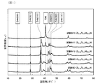
- FIG. 2 is an explanatory diagram showing an example of an X-ray diffraction pattern of a hydrogen storage alloy in Example 1.
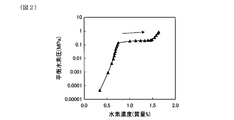
- FIG. FIG. 3 is an explanatory diagram showing an example of a pressure-hydrogen isotherm during a hydrogen storage process in Example 1.
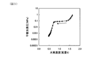
- 6 is an explanatory diagram showing an example of a pressure-hydrogen isotherm during a hydrogen release process in Example 1.
- FIG. 6 is an explanatory diagram illustrating an example of a graph for obtaining a hydrogenation entropy change ⁇ H in Example 1.
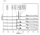
- FIG. 6 is an explanatory diagram showing an X-ray diffraction pattern of a hydrogen storage alloy in Example 2.
- FIG. 6 is an explanatory diagram showing an example of a pressure-hydrogen isotherm in a hydrogen storage process in Example 2.
- FIG. 6 is an explanatory diagram showing an example of a pressure-hydrogen isotherm during a hydrogen release process in Example 2.
- FIG. 3 is an explanatory diagram showing an example of a pressure-hydrogen is
- the hydrogen-absorbing alloy Zr (1-xy) Ti x Nb y Ni z or Zr (2-xyz) Ti x Nb y Ni z (where, 0.20 ⁇ x ⁇ 0.50,0 ⁇ y ⁇ 0. 05, 0.95 ⁇ z ⁇ 1.05).
- the crystal lattice By substituting a part of Zr with Ti, the crystal lattice can be reduced and the electronegativity can be increased as compared with the ZrNi alloy. Thereby, release of hydrogen from the hydrogen storage alloy can be promoted.
- the value of x in the composition formula is less than 0.20, the atomic ratio of Ti is low, so that hydrogen stored in the hydrogen storage alloy may not be easily released from the hydrogen storage alloy. Therefore, from the viewpoint of promoting the release of hydrogen, the value of x is set to 0.20 or more. From the same viewpoint, the value of x is preferably 0.30 or more, more preferably 0.35 or more, and further preferably 0.425 or more.
- the value of x in the composition formula is more than 0.50, in the hydrogen-absorbing alloy, for example of the TiNi phase and Zr 9 Ni 11 equality, a second phase having a crystal structure other than type B33 There is a risk of formation.
- These second phase is Zr (1-xy) Ti x Nb y Ni z phase and Zr (2-xyz) Ti x Nb y Ni z phase hydrogen storage capacity is lower than the main phase. Therefore, if the value of x exceeds 0.50, the hydrogen storage amount of the hydrogen storage alloy may be reduced due to the presence of the second phase. Therefore, from the viewpoint of increasing the hydrogen storage amount, the value of x in the composition formula is set to 0.50 or less. From the same viewpoint, the value of x is preferably 0.49 or less.
- the atomic ratio Ti / Zr of Ti to Zr is preferably 0.800 or more and 1.050 or less.
- the formation of the second phase having a crystal structure other than the B33 type can be more effectively suppressed, and a hydrogen storage alloy almost entirely having the B33 type crystal structure can be obtained.
- the hydrogen storage amount can be further increased, and the release of hydrogen stored in the hydrogen storage alloy can be further promoted.
- the value of Ti / Zr is more preferably 0.850 or more and 1.000 or less, and 0.850 or more. It is more preferably 0.975 or less, and particularly preferably 0.850 or more and 0.955 or less.
- the above-mentioned “almost the whole has a B33 type crystal structure” is derived from a crystal structure other than the B33 type when the crystal structure analysis of the hydrogen storage alloy is performed using an X-ray diffractometer. A state in which no diffraction peak is detected.
- the value of y in the composition formula is 0, that is, when Nb is not contained in the hydrogen storage alloy, a second phase having a crystal structure other than the B33 type is easily formed in the hydrogen storage alloy. Therefore, there is a possibility that the hydrogen storage amount is reduced.
- the value of y is preferably 0.005 or more, and preferably 0.01 or more. More preferred.
- the value of y in the composition formula exceeds 0.05, a second phase having a crystal structure other than the B33 type is more likely to be formed in the hydrogen storage alloy. There is a risk of inviting. Therefore, from the viewpoint of suppressing the formation of the second phase having a crystal structure other than the B33 type, the value of y in the composition formula is set to 0.05 or less. From the same viewpoint, the value of y is preferably 0.03 or less, more preferably 0.025 or less, and still more preferably 0.02 or less.
- a phase having a crystal structure other than the B33 type may become the main phase.
- a Zr—Ni binary phase diagram when the atomic ratio of Ni is higher than the specific range, a Zr 9 Ni 11 phase or a Zr 7 Ni 10 phase is likely to be formed. When these phases become main phases, there is a possibility that the hydrogen storage amount is lowered. Further, when the atomic ratio of Ni is lower than the specific range, a Zr 2 Ni phase is easily formed. When this phase becomes the main phase, hydrogen in the hydride is further stabilized, and thus there is a possibility that hydrogen release is less likely to occur.
- the “B33 type crystal structure” is the same as the CrB type structure disclosed in “Metal vol. 80 (2010) No. 7, p. 32”, for example.
- the hydrogen storage alloy can be easily produced, for example, by simply casting an alloy having the specific composition. However, in the hydrogen storage alloy immediately after casting, there are defects such as vacancies and lattice strain generated in the solidification process, and dislocations. Defects and dislocations in the hydrogen storage alloy cause a decrease in the hydrogen storage capacity. Therefore, the amount of hydrogen occlusion can be increased by reducing defects and dislocations in the hydrogen occlusion alloy.
- the ingot having the specific composition In order to remove defects and dislocations in the hydrogen storage alloy, it is preferable to heat the ingot having the specific composition to 500 ° C. or less in an inert gas atmosphere. By heating under the specific conditions, defects and dislocations can be removed while maintaining the specific crystal structure. As a result, the hydrogen storage amount of the hydrogen storage alloy can be further increased. From the viewpoint of more efficiently removing defects and dislocations and further increasing the hydrogen storage capacity, it is more preferable that the heating temperature be 400 ° C. or higher and 500 ° C. or lower.
- Example 1 Examples of the hydrogen storage alloy will be described with reference to FIGS.
- hydrogen storage alloys test bodies 1 to 19 having the compositions shown in Table 1 and Table 2 were prepared, and the crystal structure analysis and static hydrogen storage characteristics (pressure-hydrogen isothermal temperature) of the obtained hydrogen storage alloys. (Line measurement) was evaluated. Below, the manufacturing method of a hydrogen storage alloy is demonstrated in detail.
- the test body obtained using a wet cutting machine was divided into two equal parts, and the specific gravity was measured and the structure was observed using one ingot. Further, coarse pulverization with a disk mill, fine pulverization with a tungsten carbide mortar, and sieving were sequentially performed on the other ingot to produce a powder having a diameter of 20 to 40 ⁇ m. The crystal structure analysis and static hydrogen storage characteristics were evaluated using the powder obtained.
- the pulverization method of the hydrogen storage alloy is not limited to the above method.
- hydrogenation pulverization may be performed in which hydrogen occlusion and release are alternately repeated instead of fine pulverization using a tungsten carbide mortar.
- FIG. 1 shows X-ray diffraction patterns of the specimens 2, 5, 10, 17, and 18 as an example of the X-ray diffraction pattern.
- the vertical axis represents the diffraction intensity (relative intensity)
- the horizontal axis represents the diffraction angle 2 ⁇ (°).
- the crystal phase of the specimen was identified. Further, the lattice constant and the lattice volume in the crystal structure of the test specimen were calculated by the WPPF (Whole Powder Pattern Fitting) method. These results were as shown in Table 1.
- the powder X-ray diffraction was performed using CuK ⁇ 1 ray, and the output of the X-ray tube was 40 kV and 20 mA.
- the crystal structure analysis was performed using powder X-ray analysis software (“PDXL” manufactured by Rigaku Corporation).
- FIGS. 2 is a pressure-hydrogen isotherm in the hydrogen storage process
- FIG. 3 is a pressure-hydrogen isotherm in the hydrogen release process. 2 and 3, the vertical axis represents the equilibrium hydrogen pressure (MPa), and the horizontal axis represents the hydrogen concentration (% by mass).
- the enthalpy change of hydrogenation of each specimen was calculated based on the plateau pressure in the hydrogen storage process read from the pressure-hydrogen isotherm. Specifically, the plateau pressure p [MPa], the standard pressure p 0 [MPa], a temperature of T [K], the vertical axis the log (p / p 0), and the horizontal axis displays at 1000 / T The plateau pressure p at each temperature T was plotted on the graph (see FIG. 4). And the approximate straight line of these three points was calculated
- the slope of the obtained approximate straight line corresponds to the slope of the Van't Hoff equation (the following equation (1)). Therefore, the enthalpy change ⁇ H [Jmol ⁇ 1 ] of hydrogenation can be calculated by multiplying the slope of the approximate line by 1000R.
- p [MPa] is the plateau pressure in the hydrogen storage process
- p 0 [MPa] is the standard pressure
- T [K] is the temperature
- ⁇ H [Jmol ⁇ 1 ] is the change in enthalpy of hydrogenation
- ⁇ S [JK ⁇ 1 mol ⁇ 1 ] is a hydrogenation entropy change
- R is a symbol representing a gas constant.
- the standard pressure p 0 was 0.1013 MPa
- the gas constant R was 8.314 JK ⁇ 1 mol ⁇ 1 .
- the enthalpy change of dehydrogenation of each specimen was calculated based on the plateau pressure in the hydrogen release process read from the pressure-hydrogen isotherm.
- the method for calculating the enthalpy change of dehydrogenation is the same as that described above, except that the plateau pressure in the hydrogen release process is used instead of the plateau pressure in the hydrogen storage process.
- Specimens 2 to 17 have the composition in the specific range and have the same B33 type crystal structure as the ZrNi alloy (Specimen 1). . These specimens showed a tendency that the position of the X-ray diffraction peak shifted to a higher angle side and the lattice volume decreased as the substitution amount of Ti and Nb increased. Moreover, the value of the electronegativity increased in these test bodies as the substitution amount of Ti and Nb increased.
- specimens 8 to 14, 16, and 17 have a plateau pressure higher than that of specimen 1, and can secure a maximum hydrogen storage amount of 1.70% by mass or more.
- the balance between the effect of promoting the release of hydrogen and the maximum hydrogen storage amount was particularly excellent.
- the content of each component was within the specific range, but as shown in FIG. 1 and Table 1, the TiNi phase having a B2 type crystal structure was the main phase.
- the maximum hydrogen storage amount of the test body 18 was significantly lower than that of the test bodies 2 to 17.
- the amount of Nb substitution was larger than the specific range. Therefore, as shown in Table 1, although the phase having the B33 type crystal structure is the main phase, the maximum hydrogen occlusion amount was markedly lower than that of the test bodies 2 to 17.
- Example 2 In this example, as shown in Tables 3 and 4, the composition of the hydrogen storage alloy was changed.
- specimens 20 to 24 having the compositions shown in Tables 3 and 4 were produced by the same method as in Example 1. Then, the crystal structure analysis and the static hydrogen storage characteristics were evaluated in the same manner as in Example 1. These results were as shown in Tables 3 and 4.
- FIG. 5 shows the X-ray diffraction patterns of the specimens 20 to 24.
- the vertical axis in FIG. 5 is the diffraction intensity (relative intensity), and the horizontal axis is the diffraction angle 2 ⁇ (°).
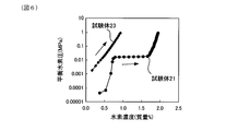
- 6 shows the pressure-hydrogen isotherm in the hydrogen storage process of the test body 21 and the test body 23, and
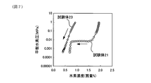
- FIG. 7 shows the pressure-hydrogen isotherm in the hydrogen release process of the test body 21 and the test body 23, respectively.
- the vertical axis represents the equilibrium hydrogen pressure (MPa)
- the horizontal axis represents the hydrogen concentration (mass%).
- 6 and 7 are pressure-hydrogen isotherms at a temperature of 100 ° C.
- the compositions of Zr, Ti, Nb and Ni in the test bodies 20 to 22 are within the specific range. Further, in the test bodies 20 to 22, the value of the Ti atomic ratio Ti / Zr to Zr is in the range of 0.800 to 1.050. Therefore, as shown in FIG. 5, in the X-ray diffraction patterns of the specimens 20 to 22, there are no diffraction peaks derived from crystal structures other than the B33 type, but only diffraction peaks derived from the B33 type crystal structure. was detected.
- test bodies 20 to 22 since a part of Zr is substituted by Ti and Nb, the position of the diffraction peak is shifted to a higher angle side and the lattice volume is reduced as compared with the ZrNi alloy (test body 1). Showed a tendency to According to the X-ray diffraction pattern shown in FIG. 5, it can be understood that almost all of the test bodies 20 to 22 have a B33 type crystal structure.
- the specimens 20 to 22 have a hydrogen storage capacity equivalent to that of the ZrNi alloy (Table 2, test specimen 1) and are much higher than the ZrNi alloy. Has a high plateau pressure. From these results, by setting the Ti atomic ratio Ti / Zr to Zr within the range of 0.800 to 1.050, hydrogen release can be further promoted while maintaining a high hydrogen storage amount in the ZrNi alloy. Easy to understand.
- the substitution amount of Ti was larger than the above specific range, and the value of Ti / Zr was larger than 1.050. Therefore, the B33 type crystal structure was not formed in the test body 23 and the test body 24, and almost the whole became a B2 type crystal structure. As a result, the maximum hydrogen storage amount was markedly lower than that of the test bodies 2 to 17 (see Table 2) and the test bodies 20 to 22.
Landscapes
- Chemical & Material Sciences (AREA)
- Engineering & Computer Science (AREA)
- Materials Engineering (AREA)
- Mechanical Engineering (AREA)
- Metallurgy (AREA)
- Organic Chemistry (AREA)
- Battery Electrode And Active Subsutance (AREA)
- Fuel Cell (AREA)
- Hydrogen, Water And Hydrids (AREA)
Abstract
高い水素吸蔵量を有するとともに、吸蔵された水素を容易に放出することができ、原料コストの変動が小さい水素吸蔵合金。水素吸蔵合金は、ZrATixNbyNiz(但し、0.20≦x≦0.50、0<y≦0.05、0.95≦z≦1.05であり、Aは1-x-yまたは2-x-y-zのいずれかである。)であり、結晶構造がB33型である。水素吸蔵合金は、例えば、上記特定の組成を有する合金を単に鋳造することにより、容易に作製することができる。
Description
本発明は、水素吸蔵合金に関する。
従来、ニッケル水素電池等のアルカリ蓄電池に用いられる負極活物質として、水素吸蔵合金が多用されている。また、近年では、燃料電池自動車等へ水素を供給するための水素ステーションにおいて、水素の貯蔵に水素吸蔵合金を用いる技術の開発が進められている。
水素吸蔵合金は、水素との親和力が高いA元素群と、水素との親和力が低いB元素群とから構成された合金であり、AB5型合金、AB2型合金及びAB型合金等が知られている。例えば、ニッケル水素電池用の負極活物質として、希土類混合金属を含むAB5型の水素吸蔵合金が既に実用化されている(特許文献1)。しかし、アルカリ蓄電池のエネルギー密度等の性能向上や水素ステーションにおける水素の貯蔵量増大の観点から、特許文献1の水素吸蔵合金よりも水素吸蔵量の高い水素吸蔵合金が望まれている。
このような水素吸蔵合金として、AB型の組成を有するZrNi(ジルコニウムニッケル)合金がある(非特許文献1)。しかし、ZrNi合金は、吸蔵した水素と反応することにより、ZrNiH3やZrNiHなどの化学的な安定性が高い水素化物を容易に生成する。そのため、ZrNi合金は、吸蔵された水素を放出しにくく、実用には適さないという問題があった。
そこで、ZrNi合金からの水素の放出を促進させるために、Zrの一部をTiで置換するとともに、Niの一部をV(バナジウム)で置換した4元系の水素吸蔵合金(特許文献2)が提案されている。
Dantzer P, Millet P, Flanagan TB. Thermodynamic Characterization of Hydride Phase Gas Growth in ZrNi-H2. Metall Mater Trans A. 2001;32A:29-38.
特許文献2の水素吸蔵合金は、前記の通り水素放出を促進させるためにVを含んでいるが、V産出地域の偏在性が高いため、社会情勢等の変化に応じて価格が変動し易い。そのため、特許文献2の水素吸蔵合金は、原料コストの変動が比較的大きいという問題がある。
本発明は、かかる背景に鑑みてなされたものであり、高い水素吸蔵量を有するとともに、吸蔵された水素を容易に放出することができ、原料コストの変動を小さくすることができる水素吸蔵合金を提供しようとするものである。
本発明の一態様は、組成がZrATixNbyNiz(但し、0.20≦x≦0.50、0<y≦0.05、0.95≦z≦1.05であり、Aは1-x-yまたは2-x-y-zのいずれかである。)であり、
結晶構造がB33型である、水素吸蔵合金にある。
結晶構造がB33型である、水素吸蔵合金にある。
上記水素吸蔵合金は、上記特定の組成及び結晶構造、即ち、ZrNi(ジルコニウムニッケル)合金におけるZrの一部がTi(チタン)及び微量のNb(ニオブ)に置換された結晶構造を有している。上記水素吸蔵合金は、ZrNi合金と同じB33型の結晶構造を有しているため、ZrNi合金と同等の水素吸蔵量を容易に実現することができる。
また、上記水素吸蔵合金は、Ti及びNbの置換量を上記特定の範囲とし、Zrをより原子半径の小さいTiやNbに置換することにより、B33型の結晶構造を維持しつつ、ZrNi合金に比べて結晶格子の体積を小さくすることができる。これにより、水素吸蔵合金中に吸蔵された水素の安定性を、ZrNi合金中に吸蔵された水素に比べて低くすることができる。
更に、Ti及びNbの置換量を上記特定の範囲とし、Zrをより電気陰性度の高いTiやNbに置換することにより、ZrNi合金に比べて水素吸蔵合金の電気陰性度の値を大きくし、水素の電気陰性度に近づけることができる。このように、合金元素と水素原子との電気陰性度の差を小さくすることにより、水素親和力を低下させ、水素吸蔵合金中に吸蔵された水素の安定性を、ZrNi合金中に吸蔵された水素に比べて低くすることができる。
そして、上述した結晶格子の縮小による安定性低下の効果と電気陰性度の増大による安定性低下の効果との相乗効果により、上記水素吸蔵合金は、ZrNi合金に比べて水素吸蔵合金からの水素の放出を促進させることができる。
以上の結果、上記水素吸蔵合金は、高い水素吸蔵量を有するとともに、水素吸蔵合金中に吸蔵された水素を容易に放出することができる。
上記水素吸蔵合金は、例えば、上記特定の組成及び結晶構造を有する鋳塊を不活性ガス雰囲気中において500℃以下に加熱することにより作製することができる。上記鋳塊を上記特定の条件で加熱することにより、上記特定の結晶構造を維持しつつ、鋳造時に生じる空孔や格子歪等の欠陥、及び、転位を除去することができる。これにより、上記水素吸蔵合金の水素吸蔵量をより高くすることができる。
上記水素吸蔵合金は、Zr(1-x-y)TixNbyNizまたはZr(2-x-y-z)TixNbyNiz(但し、0.20≦x≦0.50、0<y≦0.05、0.95≦z≦1.05)のいずれかで表される組成を有している。上記組成式中のxの値、即ちTiの置換量を上記特定の範囲とするとともに、yの値、即ちNbの置換量を上記特定の範囲にすることにより、B33型の結晶構造を維持しつつ、ZrNi合金におけるZrの一部をTi及びNbに置換することができる。
Zrの一部をTiに置換することにより、ZrNi合金に比べて結晶格子を縮小させるとともに、電気陰性度を増大させることができる。これにより、水素吸蔵合金からの水素の放出を促進させることができる。上記組成式中のxの値が0.20未満の場合には、Tiの原子数比率が低いため、上記水素吸蔵合金中に吸蔵された水素が水素吸蔵合金から放出されにくくなるおそれがある。従って、水素の放出を促進する観点から、xの値は0.20以上とする。同様の観点から、xの値は0.30以上であることが好ましく、0.35以上であることがより好ましく、0.425以上であることがさらに好ましい。
一方、上記組成式中のxの値が0.50を超える場合には、上記水素吸蔵合金中に、例えばTiNi相やZr9Ni11相等の、B33型以外の結晶構造を有する第二相が形成されるおそれがある。これらの第二相は、主相であるZr(1-x-y)TixNbyNiz相及びZr(2-x-y-z)TixNbyNiz相に比べて水素吸蔵量が低い。それ故、xの値が0.50を超える場合には、第二相の存在により、上記水素吸蔵合金の水素吸蔵量が低下するおそれがある。従って、水素吸蔵量を高くする観点から、上記組成式中のxの値は0.50以下とする。同様の観点から、xの値は0.49以下であることが好ましい。
Zrに対するTiの原子数比率Ti/Zrは、0.800以上1.050以下であることが好ましい。この場合には、B33型以外の結晶構造を有する第二相の形成をより効果的に抑制し、ほとんど全体がB33型の結晶構造を有する水素吸蔵合金を得ることができる。その結果、水素吸蔵量をより高くし、かつ、水素吸蔵合金中に吸蔵された水素の放出をより促進することができる。
水素吸蔵量を増大させる効果と水素の放出を促進する効果との両方をより高める観点から、Ti/Zrの値は、0.850以上1.000以下であることがより好ましく、0.850以上0.975以下であることがさらに好ましく、0.850以上0.955以下であることが特に好ましい。
なお、前述した「ほとんど全体がB33型の結晶構造を有する」状態とは、X線回折装置を用いて上記水素吸蔵合金の結晶構造解析を行った場合に、B33型以外の結晶構造に由来する回折ピークが検出されない状態をいう。
Zrの一部をNbに置換することにより、B33型以外の結晶構造を有する第二相の析出を抑制しつつ、Tiの置換量を多くすることができる。上記組成式中のyの値が0の場合、即ち上記水素吸蔵合金中にNbが含まれない場合には、上記水素吸蔵合金中にB33型以外の結晶構造を有する第二相が形成されやすくなり、水素吸蔵量の低下を招くおそれがある。B33型以外の結晶構造を有する第二相の形成を抑制しつつTiの置換量を多くする観点からは、yの値は0.005以上であることが好ましく、0.01以上であることがより好ましい。
一方、上記組成式中のyの値が0.05を超える場合には、かえって上記水素吸蔵合金中にB33型以外の結晶構造を有する第二相が形成されやすくなり、水素吸蔵量の低下を招くおそれがある。従って、B33型以外の結晶構造を有する第二相の形成を抑制する観点から、上記組成式中のyの値は0.05以下とする。同様の観点から、yの値は0.03以下であることが好ましく、0.025以下であることがより好ましく、0.02以下であることが更に好ましい。
また、上記組成式中のzの値、即ちZr、Ti及びNbの合計に対するNiの比率を上記特定の範囲とすることにより、B33型の結晶構造を形成しやすくすることができる。ただし、zの値が上記特定の範囲内であっても、各元素の原子数比率の微妙な違いによっては、製造の際にB33型の結晶構造を有する相が主相とならない場合もあり得る。
特に、zの値が上記特定の範囲外である場合には、B33型以外の結晶構造を有する相が主相となるおそれがある。例えば、Zr-Ni二元系状態図によれば、Niの原子数比率が上記特定の範囲よりも高い場合には、Zr9Ni11相やZr7Ni10相が形成されやすくなる。これらの相が主相となる場合には、水素吸蔵量が低下するおそれがある。また、Niの原子数比率が上記特定の範囲よりも低い場合には、Zr2Ni相が形成されやすくなる。この相が主相となる場合には、水素化物中の水素がより安定化するため、水素の放出が起こりにくくなるおそれがある。
それ故、B33型以外の結晶構造を有する相が主相となる場合には、高い水素吸蔵量を有する水素吸蔵合金や、水素を放出しやすい水素吸蔵合金が得られなくなるおそれがある。
なお、上記の「B33型の結晶構造」は、例えば「金属 vol.80(2010)No.7 32頁」等で明らかにされているCrB型構造と同一である。
なお、上記の「B33型の結晶構造」は、例えば「金属 vol.80(2010)No.7 32頁」等で明らかにされているCrB型構造と同一である。
上記水素吸蔵合金は、例えば、上記特定の組成を有する合金を単に鋳造することにより、容易に作製することができる。しかし、鋳造直後の水素吸蔵合金には、凝固過程などにおいて生じる空孔や格子歪等の欠陥、及び、転位が存在している。水素吸蔵合金中の欠陥や転位は、水素吸蔵量の低下の原因となる。そのため、水素吸蔵合金中の欠陥や転位を低減することにより、水素吸蔵量をより高くすることができる。
水素吸蔵合金中の欠陥や転位を除去するためには、不活性ガス雰囲気中において、上記特定の組成を有する鋳塊を500℃以下に加熱することが好ましい。上記特定の条件で加熱を行うことにより、上記特定の結晶構造を維持しつつ、欠陥や転位を除去することができる。その結果、上記水素吸蔵合金の水素吸蔵量をより高くすることができる。欠陥や転位の除去をより効率的に行い、水素吸蔵量を更に高くする観点からは、加熱温度を400℃以上500℃以下とすることがより好ましい。
(実施例1)
上記水素吸蔵合金の実施例について、図1~図4を用いて説明する。本例においては、表1及び表2に示す組成を有する水素吸蔵合金(試験体1~19)を作製し、得られた水素吸蔵合金の結晶構造解析及び静的水素吸蔵特性(圧力-水素等温線測定)の評価を行った。以下に、水素吸蔵合金の製造方法を詳細に説明する。
上記水素吸蔵合金の実施例について、図1~図4を用いて説明する。本例においては、表1及び表2に示す組成を有する水素吸蔵合金(試験体1~19)を作製し、得られた水素吸蔵合金の結晶構造解析及び静的水素吸蔵特性(圧力-水素等温線測定)の評価を行った。以下に、水素吸蔵合金の製造方法を詳細に説明する。
アーク溶解炉を用いて、Zr(株式会社高純度化学研究所製、ワイヤーカット品、純度98.0%)、Ti(株式会社高純度化学研究所製、粉末、純度99.0%)、Nb(株式会社高純度化学研究所製、粉末、純度99.0%)及びNi(株式会社高純度化学研究所製、粉末、純度99.9%)を溶融させ、表1に示す組成を有する水素吸蔵合金の鋳塊を作製した。この鋳塊をアルゴン雰囲気中で400~500℃に加熱し、鋳塊内の欠陥や転位を低減させた。以上により、水素吸蔵合金(試験体1~19)を作製した。
湿式切断機を用いて得られた試験体を二等分し、一方の鋳塊を用いて比重の測定及び組織観察を行った。また、他方の鋳塊にディスクミルによる粗粉砕、タングステンカーバイド製乳鉢による微粉砕及び篩い分けを順次行うことにより、直径20~40μmの粉末を作製した。これにより得られた粉末を用いて結晶構造解析及び静的水素吸蔵特性の評価を行った。
なお、水素吸蔵合金の粉砕方法は、上記の方法に限定されるものではない。例えば、粗粉砕を行った後に、タングステンカーバイド製乳鉢による微粉砕に替えて、水素の吸蔵と放出とを交互に繰り返す水素化粉砕を行ってもよい。
[結晶構造解析]
X線回折装置(株式会社リガク製「RINT(登録商標)-2000」)を用いて粉末X線回折を行い、各試験体のX線回折パターンを取得した。図1に、X線回折パターンの一例として、試験体2、5、10、17、18のX線回折パターンを示す。なお、図1における縦軸は回折強度(相対強度)であり、横軸は回折角2θ(°)である。
X線回折装置(株式会社リガク製「RINT(登録商標)-2000」)を用いて粉末X線回折を行い、各試験体のX線回折パターンを取得した。図1に、X線回折パターンの一例として、試験体2、5、10、17、18のX線回折パターンを示す。なお、図1における縦軸は回折強度(相対強度)であり、横軸は回折角2θ(°)である。
得られたX線回折パターンに基づき、試験体の結晶相を同定した。また、WPPF(Whole Powder Pattern Fitting)法により試験体の結晶構造における格子定数及び格子体積を算出した。これらの結果は、表1に示す通りであった。なお、粉末X線回折はCuKα1線を用いて行い、X線管球の出力は40kV、20mAとした。また、結晶構造解析は、粉末X線解析ソフト(株式会社リガク製「PDXL」)を用いて行った。
[静的水素吸蔵特性]
PCT(Pressure-Composition-Temperature)特性測定装置(株式会社鈴木商館製)を用い、各試験体について、互いに測定温度の異なる3本の圧力-水素等温線を取得した。その一例として、試験体17の圧力-水素等温線を図2及び図3に示す。なお、図2は水素吸蔵過程における圧力-水素等温線であり、図3は水素放出過程における圧力-水素等温線である。図2及び図3の縦軸は平衡水素圧(MPa)であり、横軸は水素濃度(質量%)である。
PCT(Pressure-Composition-Temperature)特性測定装置(株式会社鈴木商館製)を用い、各試験体について、互いに測定温度の異なる3本の圧力-水素等温線を取得した。その一例として、試験体17の圧力-水素等温線を図2及び図3に示す。なお、図2は水素吸蔵過程における圧力-水素等温線であり、図3は水素放出過程における圧力-水素等温線である。図2及び図3の縦軸は平衡水素圧(MPa)であり、横軸は水素濃度(質量%)である。
試験体1については、温度200℃における水素吸蔵過程の圧力-水素等温線から、プラトー圧及び圧力0.8MPaにおける試験体の最大水素吸蔵量を読み取った。また、試験体2~19については、温度150℃における水素吸蔵過程の圧力-水素等温線から、プラトー圧及び圧力0.8MPaにおける試験体の最大水素吸蔵量を読み取った。これらの結果は、表2に示した通りであった。
また、圧力-水素等温線から読み取った水素吸蔵過程のプラトー圧に基づき、各試験体の水素化のエンタルピー変化を算出した。具体的には、プラトー圧をp[MPa]、標準圧力をp0[MPa]、温度をT[K]とし、縦軸をlog(p/p0)、横軸を1000/Tで表示したグラフ上に各温度Tにおけるプラトー圧pをプロットした(図4参照)。そして、これら3つの点の近似直線を求めた。
得られた近似直線の傾きは、Van’t Hoffの式(下記式(1))の傾きに相当する。それ故、近似直線の傾きに1000Rを乗ずることにより、水素化のエンタルピー変化ΔH[Jmol-1]を算出することができる。

なお、上記式(1)において、p[MPa]は水素吸蔵過程におけるプラトー圧、p0[MPa]は標準圧力、T[K]は温度、ΔH[Jmol-1]は水素化のエンタルピー変化、ΔS[JK-1mol-1]は水素化のエントロピー変化、Rは気体定数を表す記号である。また、標準圧力p0は0.1013MPa、気体定数Rは8.314JK-1mol-1とした。
さらに、圧力-水素等温線から読み取った水素放出過程のプラトー圧に基づき、各試験体の脱水素化のエンタルピー変化を算出した。脱水素化のエンタルピー変化の算出方法は、水素吸蔵過程のプラトー圧に替えて水素放出過程のプラトー圧を用いた以外は、上述した方法と同様である。
水素化のエンタルピー変化及び脱水素化のエンタルピー変化の値は、表2に示した通りであった。なお、水素吸蔵反応は吸熱反応であるため、水素化のエンタルピー変化の値は負の値として示した。また、水素放出反応は発熱反応であるため、脱水素化のエンタルピー変化の値は正の値として示した。
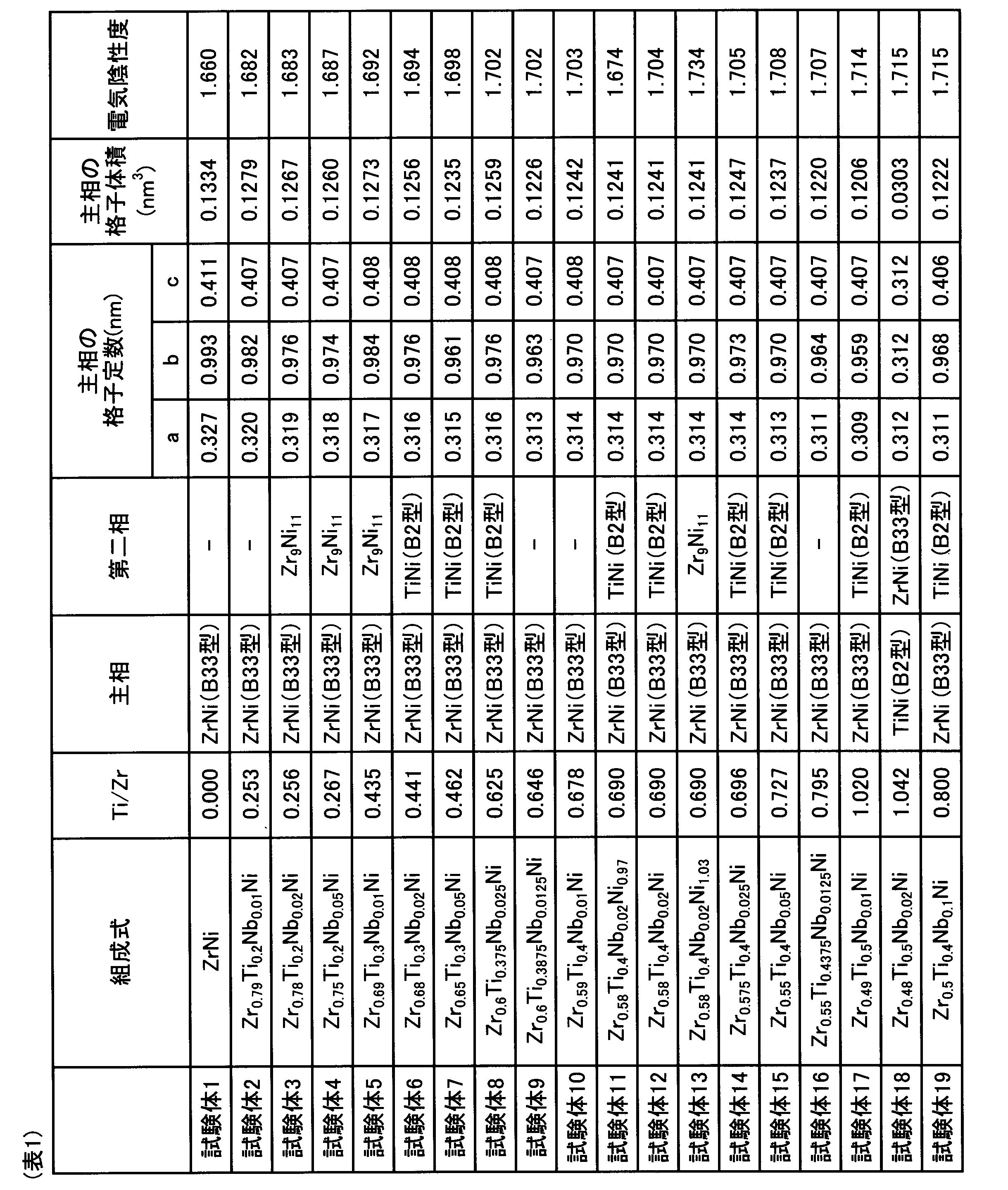
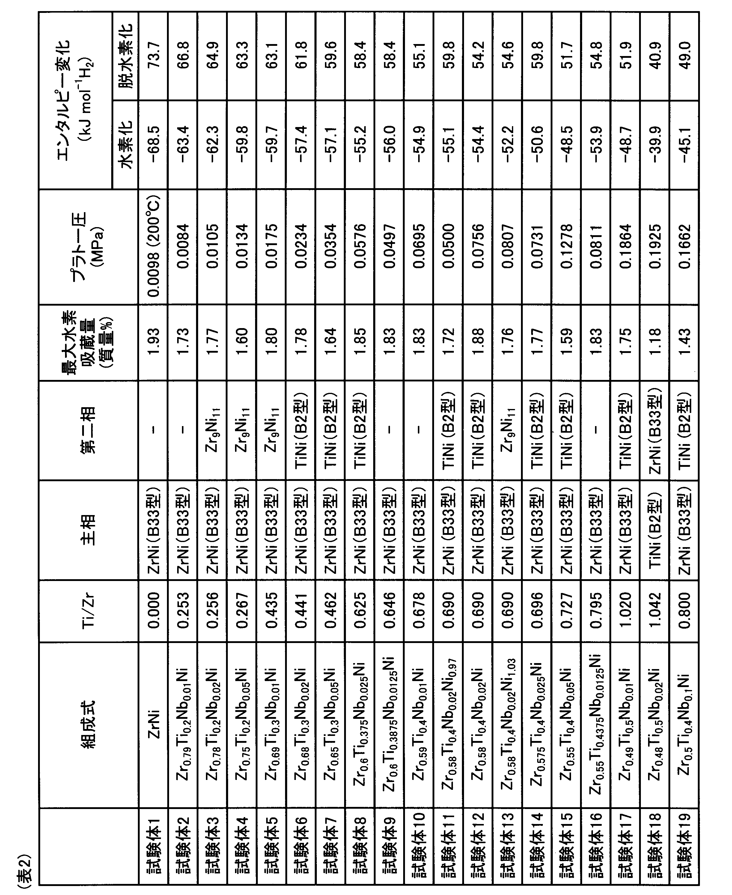
図1及び表1に示すように、試験体2~17は、上記特定の範囲の組成を有しており、かつ、ZrNi合金(試験体1)と同じB33型の結晶構造を有している。これらの試験体は、Ti及びNbの置換量が多くなるほどX線回折ピークの位置が高角度側にシフトし、格子体積が縮小する傾向を示した。また、これらの試験体は、Ti及びNbの置換量が多くなるほど電気陰性度の値が増大した。
表2に示すように、試験体3~19は、試験体1に比べてプラトー圧が高く、水素化のエンタルピー変化及び脱水素化のエンタルピー変化の絶対値が小さかった。この結果は、ZrNi合金におけるZrの一部をTi及びNbで置換することにより、ZrNi合金に比べて吸蔵された水素が放出され易くなることを示している。
これらの試験体の中でも、試験体8~14、16、17は、試験体1に比べて高いプラトー圧を有するとともに、1.70質量%以上の最大水素吸蔵量を確保することができ、水素の放出を促進する効果と最大水素吸蔵量とのバランスが特に優れていた。
試験体18は、各成分の含有量は上記特定の範囲内ではあるが、図1及び表1に示すように、B2型の結晶構造を有するTiNi相が主相となった。その結果、試験体18の最大水素吸蔵量は、試験体2~17に比べて格段に低くなった。
試験体19は、Nbの置換量が上記特定の範囲よりも多かった。そのため、表1に示すように、B33型の結晶構造を有する相が主相であるものの、試験体2~17に比べて最大水素吸蔵量が格段に低くなった。
試験体19は、Nbの置換量が上記特定の範囲よりも多かった。そのため、表1に示すように、B33型の結晶構造を有する相が主相であるものの、試験体2~17に比べて最大水素吸蔵量が格段に低くなった。
(実施例2)
本例は、表3及び表4に示すように水素吸蔵合金の組成を変更した例である。本例においては、実施例1と同様の方法により表3及び表4に示す組成を有する試験体20~24を作製した。そして、実施例1と同様の方法により結晶構造解析及び静的水素吸蔵特性の評価を行った。これらの結果は、表3及び表4に示した通りであった。
本例は、表3及び表4に示すように水素吸蔵合金の組成を変更した例である。本例においては、実施例1と同様の方法により表3及び表4に示す組成を有する試験体20~24を作製した。そして、実施例1と同様の方法により結晶構造解析及び静的水素吸蔵特性の評価を行った。これらの結果は、表3及び表4に示した通りであった。
また、図5には、試験体20~24のX線回折パターンを示した。図5の縦軸は回折強度(相対強度)であり、横軸は回折角2θ(°)である。図6には、試験体21及び試験体23の水素吸蔵過程における圧力-水素等温線を、図7には、試験体21及び試験体23の水素放出過程における圧力-水素等温線をそれぞれ示した。図6及び図7の縦軸は平衡水素圧(MPa)であり、横軸は水素濃度(質量%)である。なお、図6及び図7は、温度100℃における圧力-水素等温線である。
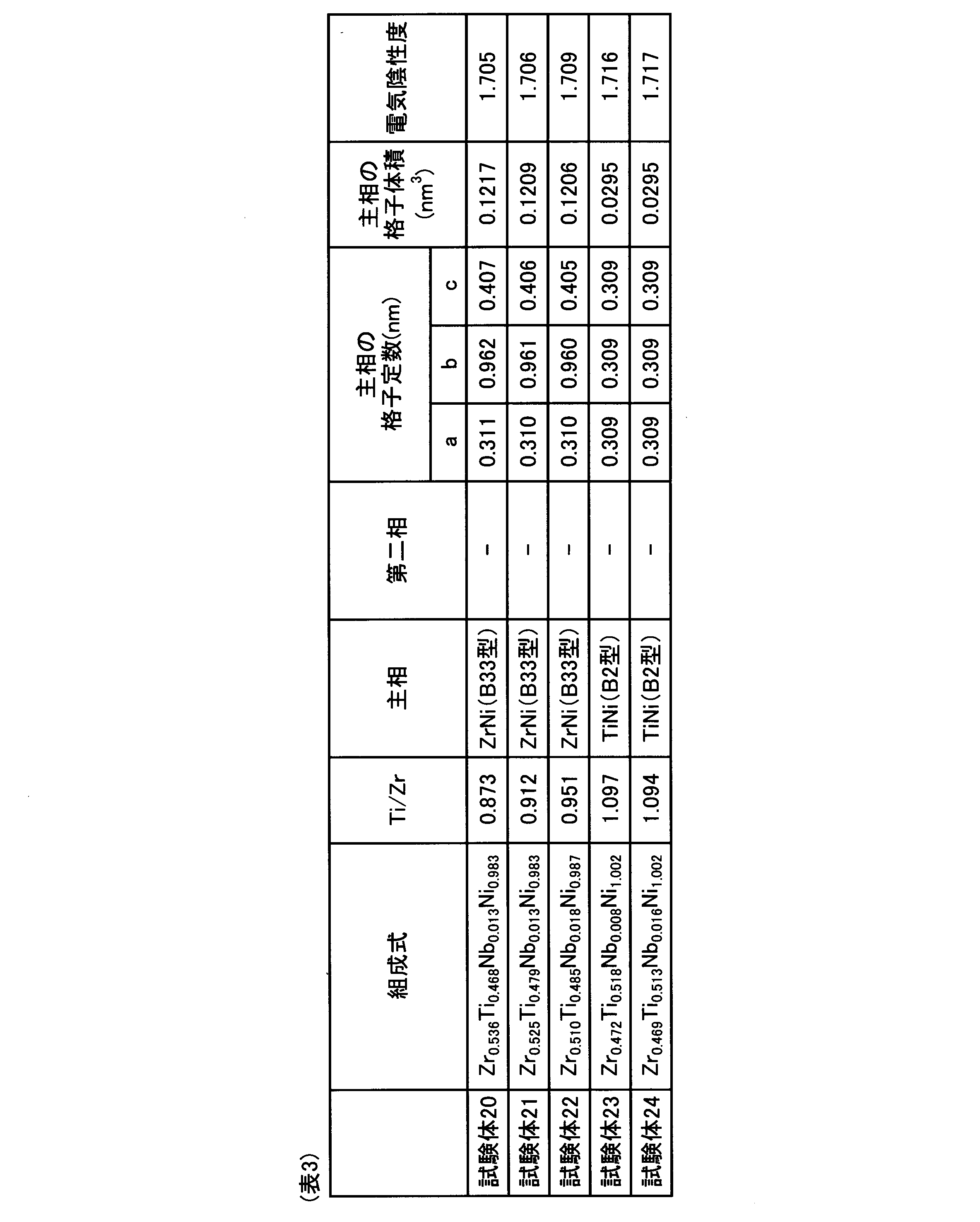

表3及び表4に示したように、試験体20~22におけるZr、Ti、Nb及びNiの組成は上記特定の範囲内にある。更に、試験体20~22における、Zrに対するTiの原子数比率Ti/Zrの値は0.800~1.050の範囲内にある。そのため、図5に示すように、試験体20~22のX線回折パターンには、B33型以外の結晶構造に由来する回折ピークが存在せず、B33型の結晶構造に由来する回折ピークのみが検出された。
また、試験体20~22は、Zrの一部がTi及びNbによって置換されているため、ZrNi合金(試験体1)に比べて回折ピークの位置が高角度側にシフトし、格子体積が縮小する傾向を示した。図5に示したX線回折パターンによれば、試験体20~22は、ほとんど全体がB33型の結晶構造を有していることが理解できる。
また、表4と表2との比較から、試験体20~22は、ZrNi合金の水素吸蔵量(表2、試験体1)と同等の水素吸蔵量を有し、かつ、ZrNi合金よりも格段に高いプラトー圧を有している。これらの結果から、Zrに対するTiの原子数比率Ti/Zrを0.800~1.050の範囲内にすることにより、ZrNi合金における高い水素吸蔵量を維持しつつ水素の放出をより促進できることが容易に理解できる。
一方、試験体23及び試験体24は、Tiの置換量が上記特定の範囲よりも多く、Ti/Zrの値が1.050よりも大きかった。そのため、試験体23及び試験体24にはB33型の結晶構造が形成されず、ほぼ全体がB2型の結晶構造となった。その結果、試験体2~17(表2参照)及び試験体20~22に比べて最大水素吸蔵量が格段に低くなった。
Claims (2)
- 組成がZrATixNbyNiz(但し、0.20≦x≦0.50、0<y≦0.05、0.95≦z≦1.05であり、Aは1-x-yまたは2-x-y-zのいずれかである。)であり、
結晶構造がB33型である、水素吸蔵合金。 - Zrに対するTiの原子数比率Ti/Zrが0.800以上1.050以下である、請求項1に記載の水素吸蔵合金。
Priority Applications (2)
| Application Number | Priority Date | Filing Date | Title |
|---|---|---|---|
| CN201880010052.3A CN110249066B (zh) | 2017-02-23 | 2018-02-20 | 储氢合金 |
| JP2019501319A JP6958611B2 (ja) | 2017-02-23 | 2018-02-20 | 水素吸蔵合金 |
Applications Claiming Priority (2)
| Application Number | Priority Date | Filing Date | Title |
|---|---|---|---|
| JP2017-032228 | 2017-02-23 | ||
| JP2017032228 | 2017-02-23 |
Publications (1)
| Publication Number | Publication Date |
|---|---|
| WO2018155400A1 true WO2018155400A1 (ja) | 2018-08-30 |
Family
ID=63253895
Family Applications (1)
| Application Number | Title | Priority Date | Filing Date |
|---|---|---|---|
| PCT/JP2018/005856 Ceased WO2018155400A1 (ja) | 2017-02-23 | 2018-02-20 | 水素吸蔵合金 |
Country Status (3)
| Country | Link |
|---|---|
| JP (1) | JP6958611B2 (ja) |
| CN (1) | CN110249066B (ja) |
| WO (1) | WO2018155400A1 (ja) |
Citations (4)
| Publication number | Priority date | Publication date | Assignee | Title |
|---|---|---|---|---|
| JPH08511128A (ja) * | 1993-10-27 | 1996-11-19 | ヒュンダイ モーター カンパニー | 電池用チタン−ニオブ−ニッケル・水素吸蔵合金 |
| JPH0927321A (ja) * | 1995-07-12 | 1997-01-28 | Japan Steel Works Ltd:The | 水素吸蔵合金電極 |
| JPH09227974A (ja) * | 1996-02-23 | 1997-09-02 | Japan Steel Works Ltd:The | 水素および水素同位体吸蔵合金 |
| JP2017168362A (ja) * | 2016-03-17 | 2017-09-21 | 愛知製鋼株式会社 | アルカリ蓄電池用負極及びその製造方法並びにアルカリ蓄電池 |
Family Cites Families (1)
| Publication number | Priority date | Publication date | Assignee | Title |
|---|---|---|---|---|
| JP6726798B2 (ja) * | 2017-02-23 | 2020-07-22 | 愛知製鋼株式会社 | アルカリ蓄電池用負極及びその製造方法並びにアルカリ蓄電池 |
-
2018
- 2018-02-20 WO PCT/JP2018/005856 patent/WO2018155400A1/ja not_active Ceased
- 2018-02-20 JP JP2019501319A patent/JP6958611B2/ja not_active Expired - Fee Related
- 2018-02-20 CN CN201880010052.3A patent/CN110249066B/zh not_active Expired - Fee Related
Patent Citations (4)
| Publication number | Priority date | Publication date | Assignee | Title |
|---|---|---|---|---|
| JPH08511128A (ja) * | 1993-10-27 | 1996-11-19 | ヒュンダイ モーター カンパニー | 電池用チタン−ニオブ−ニッケル・水素吸蔵合金 |
| JPH0927321A (ja) * | 1995-07-12 | 1997-01-28 | Japan Steel Works Ltd:The | 水素吸蔵合金電極 |
| JPH09227974A (ja) * | 1996-02-23 | 1997-09-02 | Japan Steel Works Ltd:The | 水素および水素同位体吸蔵合金 |
| JP2017168362A (ja) * | 2016-03-17 | 2017-09-21 | 愛知製鋼株式会社 | アルカリ蓄電池用負極及びその製造方法並びにアルカリ蓄電池 |
Also Published As
| Publication number | Publication date |
|---|---|
| CN110249066A (zh) | 2019-09-17 |
| JPWO2018155400A1 (ja) | 2019-12-12 |
| CN110249066B (zh) | 2021-04-30 |
| JP6958611B2 (ja) | 2021-11-02 |
Similar Documents
| Publication | Publication Date | Title |
|---|---|---|
| CN112779439A (zh) | 一种掺杂V改善ZrCo储氢合金性能的储氢材料及其制备方法 | |
| JP5449989B2 (ja) | 水素吸蔵合金及びその製造方法、並びに、水素貯蔵装置 | |
| Mao et al. | Preparation of (FeV80) 48Ti26+ xCr26 (x= 0–4) alloys by the hydride sintering method and their hydrogen storage performance | |
| JP4828986B2 (ja) | 水素吸蔵合金、水素貯蔵膜および水素貯蔵タンク | |
| Zhang et al. | Hydrogen absorption–desorption characteristics of a Gd 2 Co 7-type Sm 1.6 Mg 0.4 Ni 7 compound | |
| KR101583297B1 (ko) | 티타늄-지르코늄계 수소저장합금 및 그 제조방법 | |
| Lee et al. | Initial hydrogenation in multiphase TiFeCoNiCu high-entropy alloy for hydrogen storage | |
| JP5092747B2 (ja) | 水素吸蔵合金とその製造方法、水素吸蔵合金電極、及び二次電池 | |
| CN101538673A (zh) | 一种欠计量Laves相储氢合金及其制备方法 | |
| WO2022250093A1 (ja) | ハイエントロピー水素吸蔵合金、アルカリ蓄電池用負極及びアルカリ蓄電池 | |
| WO2023012139A1 (en) | Ab5 type-based hydrogen storage alloys, methods of preparation and uses thereof | |
| CN113201679B (zh) | 具有稳定的同晶型吸/放氢反应的ZrCo基高熵金属间化合物及其制备和应用 | |
| JP6958611B2 (ja) | 水素吸蔵合金 | |
| KR101441498B1 (ko) | 저비용 ab5계 수소저장용 합금 및 이의 제조방법 | |
| CN105861897A (zh) | 一种利用相图设计长寿命Nd-Mg-Ni储氢合金的方法 | |
| CN115989334B (zh) | 储氢材料、储氢容器和氢供给装置 | |
| US5100615A (en) | Alloys of Ti-Cr-Cu for occluding hydrogen | |
| JP2021031751A (ja) | 水素吸蔵合金 | |
| US4421718A (en) | Alloy for occlusion of hydrogen | |
| JP2017166040A (ja) | 水素吸蔵合金及びその製造方法 | |
| JP7850141B2 (ja) | 水素貯蔵材料、水素貯蔵容器及び水素供給装置 | |
| JP2004277829A (ja) | 水素吸蔵合金 | |
| JP3322458B2 (ja) | 水素吸蔵合金 | |
| JP2005305394A (ja) | 水素吸蔵材料 | |
| JP4062819B2 (ja) | 水素吸蔵合金およびその製造方法 |
Legal Events
| Date | Code | Title | Description |
|---|---|---|---|
| 121 | Ep: the epo has been informed by wipo that ep was designated in this application |
Ref document number: 18757567 Country of ref document: EP Kind code of ref document: A1 |
|
| ENP | Entry into the national phase |
Ref document number: 2019501319 Country of ref document: JP Kind code of ref document: A |
|
| NENP | Non-entry into the national phase |
Ref country code: DE |
|
| 122 | Ep: pct application non-entry in european phase |
Ref document number: 18757567 Country of ref document: EP Kind code of ref document: A1 |