WO2018123783A1 - 有機電界発光素子用材料及び有機電界発光素子 - Google Patents
有機電界発光素子用材料及び有機電界発光素子 Download PDFInfo
- Publication number
- WO2018123783A1 WO2018123783A1 PCT/JP2017/045847 JP2017045847W WO2018123783A1 WO 2018123783 A1 WO2018123783 A1 WO 2018123783A1 JP 2017045847 W JP2017045847 W JP 2017045847W WO 2018123783 A1 WO2018123783 A1 WO 2018123783A1
- Authority
- WO
- WIPO (PCT)
- Prior art keywords
- group
- carbon atoms
- formula
- organic
- compound
- Prior art date
Links
- 239000000463 material Substances 0.000 title claims description 88
- 150000001875 compounds Chemical class 0.000 claims abstract description 94
- 125000004432 carbon atom Chemical group C* 0.000 claims abstract description 55
- 125000003118 aryl group Chemical group 0.000 claims abstract description 31
- 125000006615 aromatic heterocyclic group Chemical group 0.000 claims abstract description 23
- 125000001424 substituent group Chemical group 0.000 claims abstract description 21
- 125000002029 aromatic hydrocarbon group Chemical group 0.000 claims abstract description 19
- 238000004364 calculation method Methods 0.000 claims abstract description 15
- 239000010410 layer Substances 0.000 claims description 153
- 230000000903 blocking effect Effects 0.000 claims description 35
- 238000005401 electroluminescence Methods 0.000 claims description 34
- 238000002347 injection Methods 0.000 claims description 34
- 239000007924 injection Substances 0.000 claims description 34
- 239000002019 doping agent Substances 0.000 claims description 30
- 239000000203 mixture Substances 0.000 claims description 24
- 230000005525 hole transport Effects 0.000 claims description 22
- YXFVVABEGXRONW-UHFFFAOYSA-N Toluene Chemical compound CC1=CC=CC=C1 YXFVVABEGXRONW-UHFFFAOYSA-N 0.000 claims description 18
- 239000012044 organic layer Substances 0.000 claims description 16
- 238000002884 conformational search Methods 0.000 claims description 12
- QJGQUHMNIGDVPM-UHFFFAOYSA-N nitrogen group Chemical group [N] QJGQUHMNIGDVPM-UHFFFAOYSA-N 0.000 claims description 10
- IJGRMHOSHXDMSA-UHFFFAOYSA-N Atomic nitrogen Chemical compound N#N IJGRMHOSHXDMSA-UHFFFAOYSA-N 0.000 claims description 9
- 239000002904 solvent Substances 0.000 claims description 9
- 238000006467 substitution reaction Methods 0.000 claims description 9
- YZCKVEUIGOORGS-OUBTZVSYSA-N Deuterium Chemical group [2H] YZCKVEUIGOORGS-OUBTZVSYSA-N 0.000 claims description 6
- 229910052805 deuterium Inorganic materials 0.000 claims description 6
- 229910052736 halogen Inorganic materials 0.000 claims description 6
- 150000002367 halogens Chemical group 0.000 claims description 6
- 229910052757 nitrogen Inorganic materials 0.000 claims description 6
- 125000000217 alkyl group Chemical group 0.000 claims description 5
- 238000000576 coating method Methods 0.000 claims description 5
- 239000011248 coating agent Substances 0.000 claims description 4
- 125000004986 diarylamino group Chemical group 0.000 claims description 4
- 125000002252 acyl group Chemical group 0.000 claims description 3
- 125000003342 alkenyl group Chemical group 0.000 claims description 3
- 125000000304 alkynyl group Chemical group 0.000 claims description 3
- 125000003710 aryl alkyl group Chemical group 0.000 claims description 3
- 125000004093 cyano group Chemical group *C#N 0.000 claims description 3
- 125000004663 dialkyl amino group Chemical group 0.000 claims description 3
- 125000004435 hydrogen atom Chemical group [H]* 0.000 claims description 3
- 125000000449 nitro group Chemical group [O-][N+](*)=O 0.000 claims description 3
- 125000004423 acyloxy group Chemical group 0.000 claims description 2
- 125000004453 alkoxycarbonyl group Chemical group 0.000 claims description 2
- 125000005194 alkoxycarbonyloxy group Chemical group 0.000 claims description 2
- 125000004390 alkyl sulfonyl group Chemical group 0.000 claims description 2
- 125000000623 heterocyclic group Chemical group 0.000 claims description 2
- 125000001183 hydrocarbyl group Chemical group 0.000 claims 1
- -1 tridene Chemical compound 0.000 description 28
- 230000000052 comparative effect Effects 0.000 description 26
- 229910052751 metal Inorganic materials 0.000 description 17
- 239000002184 metal Substances 0.000 description 17
- 238000007740 vapor deposition Methods 0.000 description 16
- XSCHRSMBECNVNS-UHFFFAOYSA-N benzopyrazine Natural products N1=CC=NC2=CC=CC=C21 XSCHRSMBECNVNS-UHFFFAOYSA-N 0.000 description 15
- 239000010408 film Substances 0.000 description 15
- 239000000758 substrate Substances 0.000 description 14
- UFWIBTONFRDIAS-UHFFFAOYSA-N Naphthalene Chemical compound C1=CC=CC2=CC=CC=C21 UFWIBTONFRDIAS-UHFFFAOYSA-N 0.000 description 13
- 239000010409 thin film Substances 0.000 description 13
- VQGHOUODWALEFC-UHFFFAOYSA-N 2-phenylpyridine Chemical compound C1=CC=CC=C1C1=CC=CC=N1 VQGHOUODWALEFC-UHFFFAOYSA-N 0.000 description 12
- UJOBWOGCFQCDNV-UHFFFAOYSA-N 9H-carbazole Chemical compound C1=CC=C2C3=CC=CC=C3NC2=C1 UJOBWOGCFQCDNV-UHFFFAOYSA-N 0.000 description 12
- UHOVQNZJYSORNB-UHFFFAOYSA-N Benzene Chemical compound C1=CC=CC=C1 UHOVQNZJYSORNB-UHFFFAOYSA-N 0.000 description 12
- SIKJAQJRHWYJAI-UHFFFAOYSA-N Indole Chemical compound C1=CC=C2NC=CC2=C1 SIKJAQJRHWYJAI-UHFFFAOYSA-N 0.000 description 12
- KYQCOXFCLRTKLS-UHFFFAOYSA-N Pyrazine Chemical compound C1=CN=CC=N1 KYQCOXFCLRTKLS-UHFFFAOYSA-N 0.000 description 12
- JUJWROOIHBZHMG-UHFFFAOYSA-N Pyridine Chemical compound C1=CC=NC=C1 JUJWROOIHBZHMG-UHFFFAOYSA-N 0.000 description 12
- SMWDFEZZVXVKRB-UHFFFAOYSA-N Quinoline Chemical compound N1=CC=CC2=CC=CC=C21 SMWDFEZZVXVKRB-UHFFFAOYSA-N 0.000 description 12
- YTPLMLYBLZKORZ-UHFFFAOYSA-N Thiophene Chemical compound C=1C=CSC=1 YTPLMLYBLZKORZ-UHFFFAOYSA-N 0.000 description 12
- TXCDCPKCNAJMEE-UHFFFAOYSA-N dibenzofuran Chemical compound C1=CC=C2C3=CC=CC=C3OC2=C1 TXCDCPKCNAJMEE-UHFFFAOYSA-N 0.000 description 12
- IYYZUPMFVPLQIF-UHFFFAOYSA-N dibenzothiophene Chemical compound C1=CC=C2C3=CC=CC=C3SC2=C1 IYYZUPMFVPLQIF-UHFFFAOYSA-N 0.000 description 12
- AWJUIBRHMBBTKR-UHFFFAOYSA-N isoquinoline Chemical compound C1=NC=CC2=CC=CC=C21 AWJUIBRHMBBTKR-UHFFFAOYSA-N 0.000 description 12
- 229910052782 aluminium Inorganic materials 0.000 description 11
- XAGFODPZIPBFFR-UHFFFAOYSA-N aluminium Chemical compound [Al] XAGFODPZIPBFFR-UHFFFAOYSA-N 0.000 description 11
- 230000003111 delayed effect Effects 0.000 description 11
- GVEPBJHOBDJJJI-UHFFFAOYSA-N fluoranthene Chemical compound C1=CC(C2=CC=CC=C22)=C3C2=CC=CC3=C1 GVEPBJHOBDJJJI-UHFFFAOYSA-N 0.000 description 11
- MWPLVEDNUUSJAV-UHFFFAOYSA-N anthracene Chemical compound C1=CC=CC2=CC3=CC=CC=C3C=C21 MWPLVEDNUUSJAV-UHFFFAOYSA-N 0.000 description 10
- BBEAQIROQSPTKN-UHFFFAOYSA-N pyrene Chemical compound C1=CC=C2C=CC3=CC=CC4=CC=C1C2=C43 BBEAQIROQSPTKN-UHFFFAOYSA-N 0.000 description 10
- PCNDJXKNXGMECE-UHFFFAOYSA-N Phenazine Natural products C1=CC=CC2=NC3=CC=CC=C3N=C21 PCNDJXKNXGMECE-UHFFFAOYSA-N 0.000 description 9
- IOJUPLGTWVMSFF-UHFFFAOYSA-N benzothiazole Chemical compound C1=CC=C2SC=NC2=C1 IOJUPLGTWVMSFF-UHFFFAOYSA-N 0.000 description 9
- 238000000151 deposition Methods 0.000 description 9
- RAXXELZNTBOGNW-UHFFFAOYSA-N imidazole Natural products C1=CNC=N1 RAXXELZNTBOGNW-UHFFFAOYSA-N 0.000 description 9
- FYYHWMGAXLPEAU-UHFFFAOYSA-N Magnesium Chemical compound [Mg] FYYHWMGAXLPEAU-UHFFFAOYSA-N 0.000 description 8
- 230000008021 deposition Effects 0.000 description 8
- 239000011777 magnesium Substances 0.000 description 8
- 229910052749 magnesium Inorganic materials 0.000 description 8
- YLQBMQCUIZJEEH-UHFFFAOYSA-N Furan Chemical compound C=1C=COC=1 YLQBMQCUIZJEEH-UHFFFAOYSA-N 0.000 description 7
- UFHFLCQGNIYNRP-UHFFFAOYSA-N Hydrogen Chemical compound [H][H] UFHFLCQGNIYNRP-UHFFFAOYSA-N 0.000 description 7
- 238000010438 heat treatment Methods 0.000 description 7
- 229910052739 hydrogen Inorganic materials 0.000 description 7
- 239000001257 hydrogen Substances 0.000 description 7
- VVVPGLRKXQSQSZ-UHFFFAOYSA-N indolo[3,2-c]carbazole Chemical group C1=CC=CC2=NC3=C4C5=CC=CC=C5N=C4C=CC3=C21 VVVPGLRKXQSQSZ-UHFFFAOYSA-N 0.000 description 7
- 238000000034 method Methods 0.000 description 7
- 239000000243 solution Substances 0.000 description 7
- JYEUMXHLPRZUAT-UHFFFAOYSA-N 1,2,3-triazine Chemical compound C1=CN=NN=C1 JYEUMXHLPRZUAT-UHFFFAOYSA-N 0.000 description 6
- FLBAYUMRQUHISI-UHFFFAOYSA-N 1,8-naphthyridine Chemical compound N1=CC=CC2=CC=CN=C21 FLBAYUMRQUHISI-UHFFFAOYSA-N 0.000 description 6
- KDCGOANMDULRCW-UHFFFAOYSA-N 7H-purine Chemical compound N1=CNC2=NC=NC2=C1 KDCGOANMDULRCW-UHFFFAOYSA-N 0.000 description 6
- CZPWVGJYEJSRLH-UHFFFAOYSA-N Pyrimidine Chemical compound C1=CN=CN=C1 CZPWVGJYEJSRLH-UHFFFAOYSA-N 0.000 description 6
- KAESVJOAVNADME-UHFFFAOYSA-N Pyrrole Chemical compound C=1C=CNC=1 KAESVJOAVNADME-UHFFFAOYSA-N 0.000 description 6
- DZBUGLKDJFMEHC-UHFFFAOYSA-N acridine Chemical compound C1=CC=CC2=CC3=CC=CC=C3N=C21 DZBUGLKDJFMEHC-UHFFFAOYSA-N 0.000 description 6
- WDECIBYCCFPHNR-UHFFFAOYSA-N chrysene Chemical compound C1=CC=CC2=CC=C3C4=CC=CC=C4C=CC3=C21 WDECIBYCCFPHNR-UHFFFAOYSA-N 0.000 description 6
- 239000011521 glass Substances 0.000 description 6
- PZOUSPYUWWUPPK-UHFFFAOYSA-N indole Natural products CC1=CC=CC2=C1C=CN2 PZOUSPYUWWUPPK-UHFFFAOYSA-N 0.000 description 6
- RKJUIXBNRJVNHR-UHFFFAOYSA-N indolenine Natural products C1=CC=C2CC=NC2=C1 RKJUIXBNRJVNHR-UHFFFAOYSA-N 0.000 description 6
- PQXKHYXIUOZZFA-UHFFFAOYSA-M lithium fluoride Chemical compound [Li+].[F-] PQXKHYXIUOZZFA-UHFFFAOYSA-M 0.000 description 6
- RDOWQLZANAYVLL-UHFFFAOYSA-N phenanthridine Chemical compound C1=CC=C2C3=CC=CC=C3C=NC2=C1 RDOWQLZANAYVLL-UHFFFAOYSA-N 0.000 description 6
- PBMFSQRYOILNGV-UHFFFAOYSA-N pyridazine Chemical compound C1=CC=NN=C1 PBMFSQRYOILNGV-UHFFFAOYSA-N 0.000 description 6
- UMJSCPRVCHMLSP-UHFFFAOYSA-N pyridine Natural products COC1=CC=CN=C1 UMJSCPRVCHMLSP-UHFFFAOYSA-N 0.000 description 6
- JWVCLYRUEFBMGU-UHFFFAOYSA-N quinazoline Chemical compound N1=CN=CC2=CC=CC=C21 JWVCLYRUEFBMGU-UHFFFAOYSA-N 0.000 description 6
- 229930192474 thiophene Natural products 0.000 description 6
- BCMCBBGGLRIHSE-UHFFFAOYSA-N 1,3-benzoxazole Chemical compound C1=CC=C2OC=NC2=C1 BCMCBBGGLRIHSE-UHFFFAOYSA-N 0.000 description 5
- SLGBZMMZGDRARJ-UHFFFAOYSA-N Triphenylene Natural products C1=CC=C2C3=CC=CC=C3C3=CC=CC=C3C2=C1 SLGBZMMZGDRARJ-UHFFFAOYSA-N 0.000 description 5
- 238000000295 emission spectrum Methods 0.000 description 5
- 230000007246 mechanism Effects 0.000 description 5
- 150000004866 oxadiazoles Chemical class 0.000 description 5
- YNPNZTXNASCQKK-UHFFFAOYSA-N phenanthrene Chemical compound C1=CC=C2C3=CC=CC=C3C=CC2=C1 YNPNZTXNASCQKK-UHFFFAOYSA-N 0.000 description 5
- KRLLUZSLSSIQKH-UHFFFAOYSA-N pyrrolo[3,2-c]carbazole Chemical compound C12=CC=CC=C2N=C2C1=C1N=CC=C1C=C2 KRLLUZSLSSIQKH-UHFFFAOYSA-N 0.000 description 5
- 125000005580 triphenylene group Chemical group 0.000 description 5
- 238000001771 vacuum deposition Methods 0.000 description 5
- DXBHBZVCASKNBY-UHFFFAOYSA-N 1,2-Benz(a)anthracene Chemical compound C1=CC=C2C3=CC4=CC=CC=C4C=C3C=CC2=C1 DXBHBZVCASKNBY-UHFFFAOYSA-N 0.000 description 4
- YBYIRNPNPLQARY-UHFFFAOYSA-N 1H-indene Chemical compound C1=CC=C2CC=CC2=C1 YBYIRNPNPLQARY-UHFFFAOYSA-N 0.000 description 4
- DGEZNRSVGBDHLK-UHFFFAOYSA-N [1,10]phenanthroline Chemical compound C1=CN=C2C3=NC=CC=C3C=CC2=C1 DGEZNRSVGBDHLK-UHFFFAOYSA-N 0.000 description 4
- 150000004982 aromatic amines Chemical class 0.000 description 4
- CUFNKYGDVFVPHO-UHFFFAOYSA-N azulene Chemical compound C1=CC=CC2=CC=CC2=C1 CUFNKYGDVFVPHO-UHFFFAOYSA-N 0.000 description 4
- 238000010549 co-Evaporation Methods 0.000 description 4
- VPUGDVKSAQVFFS-UHFFFAOYSA-N coronene Chemical compound C1=C(C2=C34)C=CC3=CC=C(C=C3)C4=C4C3=CC=C(C=C3)C4=C2C3=C1 VPUGDVKSAQVFFS-UHFFFAOYSA-N 0.000 description 4
- DKHNGUNXLDCATP-UHFFFAOYSA-N dipyrazino[2,3-f:2',3'-h]quinoxaline-2,3,6,7,10,11-hexacarbonitrile Chemical compound C12=NC(C#N)=C(C#N)N=C2C2=NC(C#N)=C(C#N)N=C2C2=C1N=C(C#N)C(C#N)=N2 DKHNGUNXLDCATP-UHFFFAOYSA-N 0.000 description 4
- 239000007772 electrode material Substances 0.000 description 4
- GBROPGWFBFCKAG-UHFFFAOYSA-N picene Chemical compound C1=CC2=C3C=CC=CC3=CC=C2C2=C1C1=CC=CC=C1C=C2 GBROPGWFBFCKAG-UHFFFAOYSA-N 0.000 description 4
- 238000005215 recombination Methods 0.000 description 4
- 230000006798 recombination Effects 0.000 description 4
- CSNIZNHTOVFARY-UHFFFAOYSA-N 1,2-benzothiazole Chemical compound C1=CC=C2C=NSC2=C1 CSNIZNHTOVFARY-UHFFFAOYSA-N 0.000 description 3
- KTZQTRPPVKQPFO-UHFFFAOYSA-N 1,2-benzoxazole Chemical compound C1=CC=C2C=NOC2=C1 KTZQTRPPVKQPFO-UHFFFAOYSA-N 0.000 description 3
- ODIRBFFBCSTPTO-UHFFFAOYSA-N 1,3-selenazole Chemical compound C1=C[se]C=N1 ODIRBFFBCSTPTO-UHFFFAOYSA-N 0.000 description 3
- PYWQACMPJZLKOQ-UHFFFAOYSA-N 1,3-tellurazole Chemical compound [Te]1C=CN=C1 PYWQACMPJZLKOQ-UHFFFAOYSA-N 0.000 description 3
- FCEHBMOGCRZNNI-UHFFFAOYSA-N 1-benzothiophene Chemical compound C1=CC=C2SC=CC2=C1 FCEHBMOGCRZNNI-UHFFFAOYSA-N 0.000 description 3
- TZMSYXZUNZXBOL-UHFFFAOYSA-N 10H-phenoxazine Chemical compound C1=CC=C2NC3=CC=CC=C3OC2=C1 TZMSYXZUNZXBOL-UHFFFAOYSA-N 0.000 description 3
- HYZJCKYKOHLVJF-UHFFFAOYSA-N 1H-benzimidazole Chemical compound C1=CC=C2NC=NC2=C1 HYZJCKYKOHLVJF-UHFFFAOYSA-N 0.000 description 3
- BAXOFTOLAUCFNW-UHFFFAOYSA-N 1H-indazole Chemical compound C1=CC=C2C=NNC2=C1 BAXOFTOLAUCFNW-UHFFFAOYSA-N 0.000 description 3
- AAQTWLBJPNLKHT-UHFFFAOYSA-N 1H-perimidine Chemical compound N1C=NC2=CC=CC3=CC=CC1=C32 AAQTWLBJPNLKHT-UHFFFAOYSA-N 0.000 description 3
- SVUOLADPCWQTTE-UHFFFAOYSA-N 1h-1,2-benzodiazepine Chemical compound N1N=CC=CC2=CC=CC=C12 SVUOLADPCWQTTE-UHFFFAOYSA-N 0.000 description 3
- VEPOHXYIFQMVHW-XOZOLZJESA-N 2,3-dihydroxybutanedioic acid (2S,3S)-3,4-dimethyl-2-phenylmorpholine Chemical compound OC(C(O)C(O)=O)C(O)=O.C[C@H]1[C@@H](OCCN1C)c1ccccc1 VEPOHXYIFQMVHW-XOZOLZJESA-N 0.000 description 3
- UXGVMFHEKMGWMA-UHFFFAOYSA-N 2-benzofuran Chemical compound C1=CC=CC2=COC=C21 UXGVMFHEKMGWMA-UHFFFAOYSA-N 0.000 description 3
- VHMICKWLTGFITH-UHFFFAOYSA-N 2H-isoindole Chemical compound C1=CC=CC2=CNC=C21 VHMICKWLTGFITH-UHFFFAOYSA-N 0.000 description 3
- PQJUJGAVDBINPI-UHFFFAOYSA-N 9H-thioxanthene Chemical compound C1=CC=C2CC3=CC=CC=C3SC2=C1 PQJUJGAVDBINPI-UHFFFAOYSA-N 0.000 description 3
- GJCOSYZMQJWQCA-UHFFFAOYSA-N 9H-xanthene Chemical compound C1=CC=C2CC3=CC=CC=C3OC2=C1 GJCOSYZMQJWQCA-UHFFFAOYSA-N 0.000 description 3
- PAYRUJLWNCNPSJ-UHFFFAOYSA-N Aniline Chemical compound NC1=CC=CC=C1 PAYRUJLWNCNPSJ-UHFFFAOYSA-N 0.000 description 3
- WHXSMMKQMYFTQS-UHFFFAOYSA-N Lithium Chemical compound [Li] WHXSMMKQMYFTQS-UHFFFAOYSA-N 0.000 description 3
- ZCQWOFVYLHDMMC-UHFFFAOYSA-N Oxazole Chemical compound C1=COC=N1 ZCQWOFVYLHDMMC-UHFFFAOYSA-N 0.000 description 3
- WTKZEGDFNFYCGP-UHFFFAOYSA-N Pyrazole Chemical compound C=1C=NNC=1 WTKZEGDFNFYCGP-UHFFFAOYSA-N 0.000 description 3
- BQCADISMDOOEFD-UHFFFAOYSA-N Silver Chemical compound [Ag] BQCADISMDOOEFD-UHFFFAOYSA-N 0.000 description 3
- FZWLAAWBMGSTSO-UHFFFAOYSA-N Thiazole Chemical compound C1=CSC=N1 FZWLAAWBMGSTSO-UHFFFAOYSA-N 0.000 description 3
- 150000001491 aromatic compounds Chemical class 0.000 description 3
- RFRXIWQYSOIBDI-UHFFFAOYSA-N benzarone Chemical compound CCC=1OC2=CC=CC=C2C=1C(=O)C1=CC=C(O)C=C1 RFRXIWQYSOIBDI-UHFFFAOYSA-N 0.000 description 3
- 229940049706 benzodiazepine Drugs 0.000 description 3
- PJVZQNVOUCOJGE-CALCHBBNSA-N chembl289853 Chemical compound N1([C@H]2CC[C@H](O2)N2[C]3C=CC=CC3=C3C2=C11)C2=CC=C[CH]C2=C1C1=C3C(=O)N(C)C1=O PJVZQNVOUCOJGE-CALCHBBNSA-N 0.000 description 3
- 150000002244 furazanes Chemical class 0.000 description 3
- 230000006872 improvement Effects 0.000 description 3
- 229910052738 indium Inorganic materials 0.000 description 3
- APFVFJFRJDLVQX-UHFFFAOYSA-N indium atom Chemical compound [In] APFVFJFRJDLVQX-UHFFFAOYSA-N 0.000 description 3
- HOBCFUWDNJPFHB-UHFFFAOYSA-N indolizine Chemical compound C1=CC=CN2C=CC=C21 HOBCFUWDNJPFHB-UHFFFAOYSA-N 0.000 description 3
- 229960005544 indolocarbazole Drugs 0.000 description 3
- ZPNFWUPYTFPOJU-LPYSRVMUSA-N iniprol Chemical compound C([C@H]1C(=O)NCC(=O)NCC(=O)N[C@H]2CSSC[C@H]3C(=O)N[C@@H](CCCCN)C(=O)N[C@@H](C)C(=O)N[C@@H](CCCNC(N)=N)C(=O)N[C@H](C(N[C@H](C(=O)N[C@@H](CCCNC(N)=N)C(=O)N[C@@H](CC=4C=CC(O)=CC=4)C(=O)N[C@@H](CC=4C=CC=CC=4)C(=O)N[C@@H](CC=4C=CC(O)=CC=4)C(=O)N[C@@H](CC(N)=O)C(=O)N[C@@H](C)C(=O)N[C@@H](CCCCN)C(=O)N[C@@H](C)C(=O)NCC(=O)N[C@@H](CC(C)C)C(=O)N[C@@H](CSSC[C@H](NC(=O)[C@H](CC(O)=O)NC(=O)[C@H](CCC(O)=O)NC(=O)[C@H](C)NC(=O)[C@H](CO)NC(=O)[C@H](CCCCN)NC(=O)[C@H](CC=4C=CC=CC=4)NC(=O)[C@H](CC(N)=O)NC(=O)[C@H](CC(N)=O)NC(=O)[C@H](CCCNC(N)=N)NC(=O)[C@H](CCCCN)NC(=O)[C@H](C)NC(=O)[C@H](CCCNC(N)=N)NC2=O)C(=O)N[C@@H](CCSC)C(=O)N[C@@H](CCCNC(N)=N)C(=O)N[C@@H]([C@@H](C)O)C(=O)N[C@@H](CSSC[C@H](NC(=O)[C@H](CC=2C=CC=CC=2)NC(=O)[C@H](CC(O)=O)NC(=O)[C@H]2N(CCC2)C(=O)[C@@H](N)CCCNC(N)=N)C(=O)N[C@@H](CC(C)C)C(=O)N[C@@H](CCC(O)=O)C(=O)N2[C@@H](CCC2)C(=O)N2[C@@H](CCC2)C(=O)N[C@@H](CC=2C=CC(O)=CC=2)C(=O)N[C@@H]([C@@H](C)O)C(=O)NCC(=O)N2[C@@H](CCC2)C(=O)N3)C(=O)NCC(=O)NCC(=O)N[C@@H](C)C(O)=O)C(=O)N[C@@H](CCC(N)=O)C(=O)N[C@H](C(=O)N[C@@H](CC=2C=CC=CC=2)C(=O)N[C@H](C(=O)N1)C(C)C)[C@@H](C)O)[C@@H](C)CC)=O)[C@@H](C)CC)C1=CC=C(O)C=C1 ZPNFWUPYTFPOJU-LPYSRVMUSA-N 0.000 description 3
- ZLTPDFXIESTBQG-UHFFFAOYSA-N isothiazole Chemical compound C=1C=NSC=1 ZLTPDFXIESTBQG-UHFFFAOYSA-N 0.000 description 3
- QDLAGTHXVHQKRE-UHFFFAOYSA-N lichenxanthone Natural products COC1=CC(O)=C2C(=O)C3=C(C)C=C(OC)C=C3OC2=C1 QDLAGTHXVHQKRE-UHFFFAOYSA-N 0.000 description 3
- 229910052744 lithium Inorganic materials 0.000 description 3
- 238000005259 measurement Methods 0.000 description 3
- SLIUAWYAILUBJU-UHFFFAOYSA-N pentacene Chemical compound C1=CC=CC2=CC3=CC4=CC5=CC=CC=C5C=C4C=C3C=C21 SLIUAWYAILUBJU-UHFFFAOYSA-N 0.000 description 3
- 125000002080 perylenyl group Chemical group C1(=CC=C2C=CC=C3C4=CC=CC5=CC=CC(C1=C23)=C45)* 0.000 description 3
- CSHWQDPOILHKBI-UHFFFAOYSA-N peryrene Natural products C1=CC(C2=CC=CC=3C2=C2C=CC=3)=C3C2=CC=CC3=C1 CSHWQDPOILHKBI-UHFFFAOYSA-N 0.000 description 3
- GJSGGHOYGKMUPT-UHFFFAOYSA-N phenoxathiine Chemical compound C1=CC=C2OC3=CC=CC=C3SC2=C1 GJSGGHOYGKMUPT-UHFFFAOYSA-N 0.000 description 3
- LFSXCDWNBUNEEM-UHFFFAOYSA-N phthalazine Chemical compound C1=NN=CC2=CC=CC=C21 LFSXCDWNBUNEEM-UHFFFAOYSA-N 0.000 description 3
- 229920000642 polymer Polymers 0.000 description 3
- CPNGPNLZQNNVQM-UHFFFAOYSA-N pteridine Chemical compound N1=CN=CC2=NC=CN=C21 CPNGPNLZQNNVQM-UHFFFAOYSA-N 0.000 description 3
- 229910052709 silver Inorganic materials 0.000 description 3
- 239000004332 silver Substances 0.000 description 3
- 238000004528 spin coating Methods 0.000 description 3
- 238000004544 sputter deposition Methods 0.000 description 3
- 229940042055 systemic antimycotics triazole derivative Drugs 0.000 description 3
- GVIJJXMXTUZIOD-UHFFFAOYSA-N thianthrene Chemical compound C1=CC=C2SC3=CC=CC=C3SC2=C1 GVIJJXMXTUZIOD-UHFFFAOYSA-N 0.000 description 3
- UWRZIZXBOLBCON-VOTSOKGWSA-N (e)-2-phenylethenamine Chemical class N\C=C\C1=CC=CC=C1 UWRZIZXBOLBCON-VOTSOKGWSA-N 0.000 description 2
- VERMWGQSKPXSPZ-BUHFOSPRSA-N 1-[(e)-2-phenylethenyl]anthracene Chemical class C=1C=CC2=CC3=CC=CC=C3C=C2C=1\C=C\C1=CC=CC=C1 VERMWGQSKPXSPZ-BUHFOSPRSA-N 0.000 description 2
- WJFKNYWRSNBZNX-UHFFFAOYSA-N 10H-phenothiazine Chemical compound C1=CC=C2NC3=CC=CC=C3SC2=C1 WJFKNYWRSNBZNX-UHFFFAOYSA-N 0.000 description 2
- MVWPVABZQQJTPL-UHFFFAOYSA-N 2,3-diphenylcyclohexa-2,5-diene-1,4-dione Chemical class O=C1C=CC(=O)C(C=2C=CC=CC=2)=C1C1=CC=CC=C1 MVWPVABZQQJTPL-UHFFFAOYSA-N 0.000 description 2
- LYTMVABTDYMBQK-UHFFFAOYSA-N 2-benzothiophene Chemical compound C1=CC=CC2=CSC=C21 LYTMVABTDYMBQK-UHFFFAOYSA-N 0.000 description 2
- 229910018072 Al 2 O 3 Inorganic materials 0.000 description 2
- OSKRAISUPBTHCP-UHFFFAOYSA-N Benz[j]aceanthrylene Chemical group C1=CC2=CC=CC=C2C2=C1C(C=CC1=CC=C3)=C1C3=C2 OSKRAISUPBTHCP-UHFFFAOYSA-N 0.000 description 2
- KDLHZDBZIXYQEI-UHFFFAOYSA-N Palladium Chemical compound [Pd] KDLHZDBZIXYQEI-UHFFFAOYSA-N 0.000 description 2
- 229920001609 Poly(3,4-ethylenedioxythiophene) Polymers 0.000 description 2
- 229920000265 Polyparaphenylene Polymers 0.000 description 2
- XBDYBAVJXHJMNQ-UHFFFAOYSA-N Tetrahydroanthracene Natural products C1=CC=C2C=C(CCCC3)C3=CC2=C1 XBDYBAVJXHJMNQ-UHFFFAOYSA-N 0.000 description 2
- WYURNTSHIVDZCO-UHFFFAOYSA-N Tetrahydrofuran Chemical compound C1CCOC1 WYURNTSHIVDZCO-UHFFFAOYSA-N 0.000 description 2
- 125000004054 acenaphthylenyl group Chemical group C1(=CC2=CC=CC3=CC=CC1=C23)* 0.000 description 2
- SQFPKRNUGBRTAR-UHFFFAOYSA-N acephenanthrylene Chemical group C1=CC(C=C2)=C3C2=CC2=CC=CC=C2C3=C1 SQFPKRNUGBRTAR-UHFFFAOYSA-N 0.000 description 2
- HXGDTGSAIMULJN-UHFFFAOYSA-N acetnaphthylene Natural products C1=CC(C=C2)=C3C2=CC=CC3=C1 HXGDTGSAIMULJN-UHFFFAOYSA-N 0.000 description 2
- 229910045601 alloy Inorganic materials 0.000 description 2
- 239000000956 alloy Substances 0.000 description 2
- 150000008425 anthrones Chemical class 0.000 description 2
- 150000001556 benzimidazoles Chemical class 0.000 description 2
- CYKIHIBNSFRKQP-UHFFFAOYSA-N benzo[f][1]benzothiole Chemical compound C1=CC=C2C=C(SC=C3)C3=CC2=C1 CYKIHIBNSFRKQP-UHFFFAOYSA-N 0.000 description 2
- 150000001716 carbazoles Chemical class 0.000 description 2
- 239000010406 cathode material Substances 0.000 description 2
- WCZVZNOTHYJIEI-UHFFFAOYSA-N cinnoline Chemical compound N1=NC=CC2=CC=CC=C21 WCZVZNOTHYJIEI-UHFFFAOYSA-N 0.000 description 2
- 229920001577 copolymer Polymers 0.000 description 2
- 238000002425 crystallisation Methods 0.000 description 2
- 230000008025 crystallization Effects 0.000 description 2
- 238000001035 drying Methods 0.000 description 2
- 150000008376 fluorenones Chemical class 0.000 description 2
- 230000009477 glass transition Effects 0.000 description 2
- 239000010931 gold Substances 0.000 description 2
- DDTGNKBZWQHIEH-UHFFFAOYSA-N heptalene Chemical compound C1=CC=CC=C2C=CC=CC=C21 DDTGNKBZWQHIEH-UHFFFAOYSA-N 0.000 description 2
- ACJRMEVDTSKFDP-UHFFFAOYSA-N heptaphene Chemical compound C1=CC=C2C=C(C=C3C4=CC5=CC6=CC=CC=C6C=C5C=C4C=CC3=C3)C3=CC2=C1 ACJRMEVDTSKFDP-UHFFFAOYSA-N 0.000 description 2
- UOYPNWSDSPYOSN-UHFFFAOYSA-N hexahelicene Chemical compound C1=CC=CC2=C(C=3C(=CC=C4C=CC=5C(C=34)=CC=CC=5)C=C3)C3=CC=C21 UOYPNWSDSPYOSN-UHFFFAOYSA-N 0.000 description 2
- PKIFBGYEEVFWTJ-UHFFFAOYSA-N hexaphene Chemical compound C1=CC=C2C=C3C4=CC5=CC6=CC=CC=C6C=C5C=C4C=CC3=CC2=C1 PKIFBGYEEVFWTJ-UHFFFAOYSA-N 0.000 description 2
- 229940083761 high-ceiling diuretics pyrazolone derivative Drugs 0.000 description 2
- 150000007857 hydrazones Chemical class 0.000 description 2
- 150000002430 hydrocarbons Chemical group 0.000 description 2
- 150000002460 imidazoles Chemical class 0.000 description 2
- 150000002467 indacenes Chemical class 0.000 description 2
- 229940079865 intestinal antiinfectives imidazole derivative Drugs 0.000 description 2
- OVPVGJFDFSJUIG-UHFFFAOYSA-N octalene Chemical compound C1=CC=CC=C2C=CC=CC=CC2=C1 OVPVGJFDFSJUIG-UHFFFAOYSA-N 0.000 description 2
- 150000004893 oxazines Chemical class 0.000 description 2
- 150000007978 oxazole derivatives Chemical class 0.000 description 2
- 230000003647 oxidation Effects 0.000 description 2
- 238000007254 oxidation reaction Methods 0.000 description 2
- TWNQGVIAIRXVLR-UHFFFAOYSA-N oxo(oxoalumanyloxy)alumane Chemical compound O=[Al]O[Al]=O TWNQGVIAIRXVLR-UHFFFAOYSA-N 0.000 description 2
- NRZWYNLTFLDQQX-UHFFFAOYSA-N p-tert-Amylphenol Chemical compound CCC(C)(C)C1=CC=C(O)C=C1 NRZWYNLTFLDQQX-UHFFFAOYSA-N 0.000 description 2
- GUVXZFRDPCKWEM-UHFFFAOYSA-N pentalene Chemical compound C1=CC2=CC=CC2=C1 GUVXZFRDPCKWEM-UHFFFAOYSA-N 0.000 description 2
- XDJOIMJURHQYDW-UHFFFAOYSA-N phenalene Chemical compound C1=CC(CC=C2)=C3C2=CC=CC3=C1 XDJOIMJURHQYDW-UHFFFAOYSA-N 0.000 description 2
- 229950000688 phenothiazine Drugs 0.000 description 2
- 150000004986 phenylenediamines Chemical class 0.000 description 2
- BASFCYQUMIYNBI-UHFFFAOYSA-N platinum Chemical compound [Pt] BASFCYQUMIYNBI-UHFFFAOYSA-N 0.000 description 2
- 229920000553 poly(phenylenevinylene) Polymers 0.000 description 2
- 229920000123 polythiophene Polymers 0.000 description 2
- 150000004033 porphyrin derivatives Chemical class 0.000 description 2
- 238000007639 printing Methods 0.000 description 2
- LNKHTYQPVMAJSF-UHFFFAOYSA-N pyranthrene Chemical compound C1=C2C3=CC=CC=C3C=C(C=C3)C2=C2C3=CC3=C(C=CC=C4)C4=CC4=CC=C1C2=C34 LNKHTYQPVMAJSF-UHFFFAOYSA-N 0.000 description 2
- JEXVQSWXXUJEMA-UHFFFAOYSA-N pyrazol-3-one Chemical class O=C1C=CN=N1 JEXVQSWXXUJEMA-UHFFFAOYSA-N 0.000 description 2
- 150000003219 pyrazolines Chemical class 0.000 description 2
- FYNROBRQIVCIQF-UHFFFAOYSA-N pyrrolo[3,2-b]pyrrole-5,6-dione Chemical class C1=CN=C2C(=O)C(=O)N=C21 FYNROBRQIVCIQF-UHFFFAOYSA-N 0.000 description 2
- MCJGNVYPOGVAJF-UHFFFAOYSA-N quinolin-8-ol Chemical class C1=CN=C2C(O)=CC=CC2=C1 MCJGNVYPOGVAJF-UHFFFAOYSA-N 0.000 description 2
- 229910052761 rare earth metal Inorganic materials 0.000 description 2
- 150000002910 rare earth metals Chemical class 0.000 description 2
- FMKFBRKHHLWKDB-UHFFFAOYSA-N rubicene Chemical compound C12=CC=CC=C2C2=CC=CC3=C2C1=C1C=CC=C2C4=CC=CC=C4C3=C21 FMKFBRKHHLWKDB-UHFFFAOYSA-N 0.000 description 2
- 239000002356 single layer Substances 0.000 description 2
- PJANXHGTPQOBST-UHFFFAOYSA-N stilbene Chemical class C=1C=CC=CC=1C=CC1=CC=CC=C1 PJANXHGTPQOBST-UHFFFAOYSA-N 0.000 description 2
- 125000005504 styryl group Chemical group 0.000 description 2
- IFLREYGFSNHWGE-UHFFFAOYSA-N tetracene Chemical compound C1=CC=CC2=CC3=CC4=CC=CC=C4C=C3C=C21 IFLREYGFSNHWGE-UHFFFAOYSA-N 0.000 description 2
- NQRYJNQNLNOLGT-UHFFFAOYSA-N tetrahydropyridine hydrochloride Natural products C1CCNCC1 NQRYJNQNLNOLGT-UHFFFAOYSA-N 0.000 description 2
- KTQYWNARBMKMCX-UHFFFAOYSA-N tetraphenylene Chemical group C1=CC=C2C3=CC=CC=C3C3=CC=CC=C3C3=CC=CC=C3C2=C1 KTQYWNARBMKMCX-UHFFFAOYSA-N 0.000 description 2
- 229920001187 thermosetting polymer Polymers 0.000 description 2
- 229910052723 transition metal Inorganic materials 0.000 description 2
- 150000003624 transition metals Chemical class 0.000 description 2
- 239000012780 transparent material Substances 0.000 description 2
- PGXOVVAJURGPLL-UHFFFAOYSA-N trinaphthylene Chemical group C1=CC=C2C=C3C4=CC5=CC=CC=C5C=C4C4=CC5=CC=CC=C5C=C4C3=CC2=C1 PGXOVVAJURGPLL-UHFFFAOYSA-N 0.000 description 2
- XLYOFNOQVPJJNP-UHFFFAOYSA-N water Substances O XLYOFNOQVPJJNP-UHFFFAOYSA-N 0.000 description 2
- KLCLIOISYBHYDZ-UHFFFAOYSA-N 1,4,4-triphenylbuta-1,3-dienylbenzene Chemical class C=1C=CC=CC=1C(C=1C=CC=CC=1)=CC=C(C=1C=CC=CC=1)C1=CC=CC=C1 KLCLIOISYBHYDZ-UHFFFAOYSA-N 0.000 description 1
- ZHFLRRPGAVPNMB-UHFFFAOYSA-N 1-[3-(9h-carbazol-1-yl)phenyl]-9h-carbazole Chemical compound C12=CC=CC=C2NC2=C1C=CC=C2C1=CC(C2=C3NC=4C(C3=CC=C2)=CC=CC=4)=CC=C1 ZHFLRRPGAVPNMB-UHFFFAOYSA-N 0.000 description 1
- ILFYOWGJBKEMSK-UHFFFAOYSA-N 10h-phenoselenazine Chemical compound C1=CC=C2NC3=CC=CC=C3[Se]C2=C1 ILFYOWGJBKEMSK-UHFFFAOYSA-N 0.000 description 1
- AGIJRRREJXSQJR-UHFFFAOYSA-N 2h-thiazine Chemical compound N1SC=CC=C1 AGIJRRREJXSQJR-UHFFFAOYSA-N 0.000 description 1
- LGLDSEPDYUTBNZ-UHFFFAOYSA-N 3-phenylbuta-1,3-dien-2-ylbenzene Chemical class C=1C=CC=CC=1C(=C)C(=C)C1=CC=CC=C1 LGLDSEPDYUTBNZ-UHFFFAOYSA-N 0.000 description 1
- ZYASLTYCYTYKFC-UHFFFAOYSA-N 9-methylidenefluorene Chemical class C1=CC=C2C(=C)C3=CC=CC=C3C2=C1 ZYASLTYCYTYKFC-UHFFFAOYSA-N 0.000 description 1
- ROFVEXUMMXZLPA-UHFFFAOYSA-N Bipyridyl Chemical class N1=CC=CC=C1C1=CC=CC=N1 ROFVEXUMMXZLPA-UHFFFAOYSA-N 0.000 description 1
- 125000003860 C1-C20 alkoxy group Chemical group 0.000 description 1
- OKTJSMMVPCPJKN-UHFFFAOYSA-N Carbon Chemical compound [C] OKTJSMMVPCPJKN-UHFFFAOYSA-N 0.000 description 1
- RAPBNVDSDCTNRC-UHFFFAOYSA-N Chlorobenzilate Chemical compound C=1C=C(Cl)C=CC=1C(O)(C(=O)OCC)C1=CC=C(Cl)C=C1 RAPBNVDSDCTNRC-UHFFFAOYSA-N 0.000 description 1
- RYGMFSIKBFXOCR-UHFFFAOYSA-N Copper Chemical compound [Cu] RYGMFSIKBFXOCR-UHFFFAOYSA-N 0.000 description 1
- KLIHYVJAYWCEDM-UHFFFAOYSA-N Dibenz[a,j]anthracene Chemical compound C1=CC=CC2=C(C=C3C4=CC=CC=C4C=CC3=C3)C3=CC=C21 KLIHYVJAYWCEDM-UHFFFAOYSA-N 0.000 description 1
- DGAQECJNVWCQMB-PUAWFVPOSA-M Ilexoside XXIX Chemical compound C[C@@H]1CC[C@@]2(CC[C@@]3(C(=CC[C@H]4[C@]3(CC[C@@H]5[C@@]4(CC[C@@H](C5(C)C)OS(=O)(=O)[O-])C)C)[C@@H]2[C@]1(C)O)C)C(=O)O[C@H]6[C@@H]([C@H]([C@@H]([C@H](O6)CO)O)O)O.[Na+] DGAQECJNVWCQMB-PUAWFVPOSA-M 0.000 description 1
- 229910000799 K alloy Inorganic materials 0.000 description 1
- CBENFWSGALASAD-UHFFFAOYSA-N Ozone Chemical compound [O-][O+]=O CBENFWSGALASAD-UHFFFAOYSA-N 0.000 description 1
- NRCMAYZCPIVABH-UHFFFAOYSA-N Quinacridone Chemical class N1C2=CC=CC=C2C(=O)C2=C1C=C1C(=O)C3=CC=CC=C3NC1=C2 NRCMAYZCPIVABH-UHFFFAOYSA-N 0.000 description 1
- KJTLSVCANCCWHF-UHFFFAOYSA-N Ruthenium Chemical compound [Ru] KJTLSVCANCCWHF-UHFFFAOYSA-N 0.000 description 1
- XUIMIQQOPSSXEZ-UHFFFAOYSA-N Silicon Chemical compound [Si] XUIMIQQOPSSXEZ-UHFFFAOYSA-N 0.000 description 1
- 229910006404 SnO 2 Inorganic materials 0.000 description 1
- ATJFFYVFTNAWJD-UHFFFAOYSA-N Tin Chemical compound [Sn] ATJFFYVFTNAWJD-UHFFFAOYSA-N 0.000 description 1
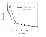
- 238000002441 X-ray diffraction Methods 0.000 description 1
- ILYGRCGTUMHLGR-UHFFFAOYSA-N acenaphtho[1,2-j]fluoranthene Chemical compound C1=CC2=CC=CC(C=3C4=C5C=6C=CC=C7C=CC=C(C=67)C5=CC=3)=C2C4=C1 ILYGRCGTUMHLGR-UHFFFAOYSA-N 0.000 description 1
- 150000001251 acridines Chemical class 0.000 description 1
- 239000000654 additive Substances 0.000 description 1
- 230000000996 additive effect Effects 0.000 description 1
- 150000001412 amines Chemical class 0.000 description 1
- 239000010405 anode material Substances 0.000 description 1
- 229940058303 antinematodal benzimidazole derivative Drugs 0.000 description 1
- 229940054051 antipsychotic indole derivative Drugs 0.000 description 1
- 229940027998 antiseptic and disinfectant acridine derivative Drugs 0.000 description 1
- 229940027991 antiseptic and disinfectant quinoline derivative Drugs 0.000 description 1
- 230000004888 barrier function Effects 0.000 description 1
- TUAHORSUHVUKBD-UHFFFAOYSA-N benzo[c]phenanthrene Chemical compound C1=CC=CC2=C3C4=CC=CC=C4C=CC3=CC=C21 TUAHORSUHVUKBD-UHFFFAOYSA-N 0.000 description 1
- XJHABGPPCLHLLV-UHFFFAOYSA-N benzo[de]isoquinoline-1,3-dione Chemical class C1=CC(C(=O)NC2=O)=C3C2=CC=CC3=C1 XJHABGPPCLHLLV-UHFFFAOYSA-N 0.000 description 1
- 150000008359 benzonitriles Chemical class 0.000 description 1
- 230000015572 biosynthetic process Effects 0.000 description 1
- UFVXQDWNSAGPHN-UHFFFAOYSA-K bis[(2-methylquinolin-8-yl)oxy]-(4-phenylphenoxy)alumane Chemical compound [Al+3].C1=CC=C([O-])C2=NC(C)=CC=C21.C1=CC=C([O-])C2=NC(C)=CC=C21.C1=CC([O-])=CC=C1C1=CC=CC=C1 UFVXQDWNSAGPHN-UHFFFAOYSA-K 0.000 description 1
- 150000001718 carbodiimides Chemical class 0.000 description 1
- 229910052799 carbon Inorganic materials 0.000 description 1
- 229940125898 compound 5 Drugs 0.000 description 1
- 229920001940 conductive polymer Polymers 0.000 description 1
- 239000004020 conductor Substances 0.000 description 1
- 150000004696 coordination complex Chemical class 0.000 description 1
- 229910052802 copper Inorganic materials 0.000 description 1
- 239000010949 copper Substances 0.000 description 1
- 150000004699 copper complex Chemical class 0.000 description 1
- 150000001893 coumarin derivatives Chemical class 0.000 description 1
- ZSWFCLXCOIISFI-UHFFFAOYSA-N cyclopentadiene Chemical class C1C=CC=C1 ZSWFCLXCOIISFI-UHFFFAOYSA-N 0.000 description 1
- 230000007423 decrease Effects 0.000 description 1
- LHRCREOYAASXPZ-UHFFFAOYSA-N dibenz[a,h]anthracene Chemical compound C1=CC=C2C(C=C3C=CC=4C(C3=C3)=CC=CC=4)=C3C=CC2=C1 LHRCREOYAASXPZ-UHFFFAOYSA-N 0.000 description 1
- AMDQVKPUZIXQFC-UHFFFAOYSA-N dinaphthylene dioxide Chemical compound O1C(C2=C34)=CC=CC2=CC=C3OC2=CC=CC3=CC=C1C4=C32 AMDQVKPUZIXQFC-UHFFFAOYSA-N 0.000 description 1
- 238000012617 force field calculation Methods 0.000 description 1
- 230000004927 fusion Effects 0.000 description 1
- PCHJSUWPFVWCPO-UHFFFAOYSA-N gold Chemical compound [Au] PCHJSUWPFVWCPO-UHFFFAOYSA-N 0.000 description 1
- 229910052737 gold Inorganic materials 0.000 description 1
- QSQIGGCOCHABAP-UHFFFAOYSA-N hexacene Chemical compound C1=CC=CC2=CC3=CC4=CC5=CC6=CC=CC=C6C=C5C=C4C=C3C=C21 QSQIGGCOCHABAP-UHFFFAOYSA-N 0.000 description 1
- AMGQUBHHOARCQH-UHFFFAOYSA-N indium;oxotin Chemical compound [In].[Sn]=O AMGQUBHHOARCQH-UHFFFAOYSA-N 0.000 description 1
- 150000002475 indoles Chemical class 0.000 description 1
- 238000007641 inkjet printing Methods 0.000 description 1
- 150000002503 iridium Chemical class 0.000 description 1
- 229910052741 iridium Inorganic materials 0.000 description 1
- GKOZUEZYRPOHIO-UHFFFAOYSA-N iridium atom Chemical compound [Ir] GKOZUEZYRPOHIO-UHFFFAOYSA-N 0.000 description 1
- 229910052747 lanthanoid Inorganic materials 0.000 description 1
- 150000002602 lanthanoids Chemical class 0.000 description 1
- 238000004020 luminiscence type Methods 0.000 description 1
- 238000005297 material degradation process Methods 0.000 description 1
- 150000002739 metals Chemical class 0.000 description 1
- 238000002156 mixing Methods 0.000 description 1
- KKFHAJHLJHVUDM-UHFFFAOYSA-N n-vinylcarbazole Chemical class C1=CC=C2N(C=C)C3=CC=CC=C3C2=C1 KKFHAJHLJHVUDM-UHFFFAOYSA-N 0.000 description 1
- AODWRBPUCXIRKB-UHFFFAOYSA-N naphthalene perylene Chemical group C1=CC=CC2=CC=CC=C21.C1=CC(C2=CC=CC=3C2=C2C=CC=3)=C3C2=CC=CC3=C1 AODWRBPUCXIRKB-UHFFFAOYSA-N 0.000 description 1
- JAUCCASEHMVMPM-UHFFFAOYSA-N naphtho[2,1-e][1,3]benzoxazole Chemical compound C1=CC2=CC=CC=C2C2=C1C(N=CO1)=C1C=C2 JAUCCASEHMVMPM-UHFFFAOYSA-N 0.000 description 1
- ACIUFBMENRNYHI-UHFFFAOYSA-N naphtho[2,1-f]isoquinoline Chemical compound C1=CN=CC2=CC=C3C4=CC=CC=C4C=CC3=C21 ACIUFBMENRNYHI-UHFFFAOYSA-N 0.000 description 1
- 239000012299 nitrogen atmosphere Substances 0.000 description 1
- 239000003960 organic solvent Substances 0.000 description 1
- 125000002524 organometallic group Chemical group 0.000 description 1
- 229910052762 osmium Inorganic materials 0.000 description 1
- SYQBFIAQOQZEGI-UHFFFAOYSA-N osmium atom Chemical compound [Os] SYQBFIAQOQZEGI-UHFFFAOYSA-N 0.000 description 1
- MPQXHAGKBWFSNV-UHFFFAOYSA-N oxidophosphanium Chemical class [PH3]=O MPQXHAGKBWFSNV-UHFFFAOYSA-N 0.000 description 1
- 238000012856 packing Methods 0.000 description 1
- 229910052763 palladium Inorganic materials 0.000 description 1
- DGBWPZSGHAXYGK-UHFFFAOYSA-N perinone Chemical class C12=NC3=CC=CC=C3N2C(=O)C2=CC=C3C4=C2C1=CC=C4C(=O)N1C2=CC=CC=C2N=C13 DGBWPZSGHAXYGK-UHFFFAOYSA-N 0.000 description 1
- 150000002988 phenazines Chemical class 0.000 description 1
- 150000002991 phenoxazines Chemical class 0.000 description 1
- 238000000206 photolithography Methods 0.000 description 1
- IEQIEDJGQAUEQZ-UHFFFAOYSA-N phthalocyanine Chemical class N1C(N=C2C3=CC=CC=C3C(N=C3C4=CC=CC=C4C(=N4)N3)=N2)=C(C=CC=C2)C2=C1N=C1C2=CC=CC=C2C4=N1 IEQIEDJGQAUEQZ-UHFFFAOYSA-N 0.000 description 1
- 229920003023 plastic Polymers 0.000 description 1
- 229910052697 platinum Inorganic materials 0.000 description 1
- 229920003227 poly(N-vinyl carbazole) Chemical class 0.000 description 1
- 229920000548 poly(silane) polymer Chemical class 0.000 description 1
- 229920000172 poly(styrenesulfonic acid) Polymers 0.000 description 1
- 229920002098 polyfluorene Polymers 0.000 description 1
- 239000002861 polymer material Substances 0.000 description 1
- 229920006389 polyphenyl polymer Polymers 0.000 description 1
- 229940005642 polystyrene sulfonic acid Drugs 0.000 description 1
- BITYAPCSNKJESK-UHFFFAOYSA-N potassiosodium Chemical compound [Na].[K] BITYAPCSNKJESK-UHFFFAOYSA-N 0.000 description 1
- 230000008569 process Effects 0.000 description 1
- 150000005255 pyrrolopyridines Chemical class 0.000 description 1
- 239000010453 quartz Substances 0.000 description 1
- 150000003248 quinolines Chemical class 0.000 description 1
- QEVBPWGFJKJQHA-UHFFFAOYSA-N quinolino[6,5-f]quinoline Chemical compound C1=CC=NC2=CC=C(C=3C(=NC=CC=3)C=C3)C3=C21 QEVBPWGFJKJQHA-UHFFFAOYSA-N 0.000 description 1
- 230000009467 reduction Effects 0.000 description 1
- 229910052702 rhenium Inorganic materials 0.000 description 1
- WUAPFZMCVAUBPE-UHFFFAOYSA-N rhenium atom Chemical compound [Re] WUAPFZMCVAUBPE-UHFFFAOYSA-N 0.000 description 1
- 229910052703 rhodium Inorganic materials 0.000 description 1
- 239000010948 rhodium Substances 0.000 description 1
- MHOVAHRLVXNVSD-UHFFFAOYSA-N rhodium atom Chemical compound [Rh] MHOVAHRLVXNVSD-UHFFFAOYSA-N 0.000 description 1
- 229910052707 ruthenium Inorganic materials 0.000 description 1
- 150000004756 silanes Chemical class 0.000 description 1
- 229910052710 silicon Inorganic materials 0.000 description 1
- 239000010703 silicon Substances 0.000 description 1
- VYPSYNLAJGMNEJ-UHFFFAOYSA-N silicon dioxide Inorganic materials O=[Si]=O VYPSYNLAJGMNEJ-UHFFFAOYSA-N 0.000 description 1
- 229910052708 sodium Inorganic materials 0.000 description 1
- 239000011734 sodium Substances 0.000 description 1
- 238000005507 spraying Methods 0.000 description 1
- 238000003756 stirring Methods 0.000 description 1
- 239000000126 substance Substances 0.000 description 1
- 150000003457 sulfones Chemical class 0.000 description 1
- IBBLKSWSCDAPIF-UHFFFAOYSA-N thiopyran Chemical compound S1C=CC=C=C1 IBBLKSWSCDAPIF-UHFFFAOYSA-N 0.000 description 1
- NZFNXWQNBYZDAQ-UHFFFAOYSA-N thioridazine hydrochloride Chemical class Cl.C12=CC(SC)=CC=C2SC2=CC=CC=C2N1CCC1CCCCN1C NZFNXWQNBYZDAQ-UHFFFAOYSA-N 0.000 description 1
- 238000002834 transmittance Methods 0.000 description 1
- TVIVIEFSHFOWTE-UHFFFAOYSA-K tri(quinolin-8-yloxy)alumane Chemical class [Al+3].C1=CN=C2C([O-])=CC=CC2=C1.C1=CN=C2C([O-])=CC=CC2=C1.C1=CN=C2C([O-])=CC=CC2=C1 TVIVIEFSHFOWTE-UHFFFAOYSA-K 0.000 description 1
- 238000005019 vapor deposition process Methods 0.000 description 1
- 230000000007 visual effect Effects 0.000 description 1
Images

Classifications
-
- C—CHEMISTRY; METALLURGY
- C07—ORGANIC CHEMISTRY
- C07D—HETEROCYCLIC COMPOUNDS
- C07D487/00—Heterocyclic compounds containing nitrogen atoms as the only ring hetero atoms in the condensed system, not provided for by groups C07D451/00 - C07D477/00
- C07D487/02—Heterocyclic compounds containing nitrogen atoms as the only ring hetero atoms in the condensed system, not provided for by groups C07D451/00 - C07D477/00 in which the condensed system contains two hetero rings
- C07D487/04—Ortho-condensed systems
-
- C—CHEMISTRY; METALLURGY
- C09—DYES; PAINTS; POLISHES; NATURAL RESINS; ADHESIVES; COMPOSITIONS NOT OTHERWISE PROVIDED FOR; APPLICATIONS OF MATERIALS NOT OTHERWISE PROVIDED FOR
- C09K—MATERIALS FOR MISCELLANEOUS APPLICATIONS, NOT PROVIDED FOR ELSEWHERE
- C09K11/00—Luminescent, e.g. electroluminescent, chemiluminescent materials
- C09K11/06—Luminescent, e.g. electroluminescent, chemiluminescent materials containing organic luminescent materials
-
- H—ELECTRICITY
- H10—SEMICONDUCTOR DEVICES; ELECTRIC SOLID-STATE DEVICES NOT OTHERWISE PROVIDED FOR
- H10K—ORGANIC ELECTRIC SOLID-STATE DEVICES
- H10K50/00—Organic light-emitting devices
- H10K50/10—OLEDs or polymer light-emitting diodes [PLED]
- H10K50/11—OLEDs or polymer light-emitting diodes [PLED] characterised by the electroluminescent [EL] layers
-
- H—ELECTRICITY
- H10—SEMICONDUCTOR DEVICES; ELECTRIC SOLID-STATE DEVICES NOT OTHERWISE PROVIDED FOR
- H10K—ORGANIC ELECTRIC SOLID-STATE DEVICES
- H10K85/00—Organic materials used in the body or electrodes of devices covered by this subclass
- H10K85/60—Organic compounds having low molecular weight
- H10K85/649—Aromatic compounds comprising a hetero atom
- H10K85/654—Aromatic compounds comprising a hetero atom comprising only nitrogen as heteroatom
-
- H—ELECTRICITY
- H10—SEMICONDUCTOR DEVICES; ELECTRIC SOLID-STATE DEVICES NOT OTHERWISE PROVIDED FOR
- H10K—ORGANIC ELECTRIC SOLID-STATE DEVICES
- H10K85/00—Organic materials used in the body or electrodes of devices covered by this subclass
- H10K85/60—Organic compounds having low molecular weight
- H10K85/649—Aromatic compounds comprising a hetero atom
- H10K85/657—Polycyclic condensed heteroaromatic hydrocarbons
- H10K85/6572—Polycyclic condensed heteroaromatic hydrocarbons comprising only nitrogen in the heteroaromatic polycondensed ring system, e.g. phenanthroline or carbazole
-
- H—ELECTRICITY
- H10—SEMICONDUCTOR DEVICES; ELECTRIC SOLID-STATE DEVICES NOT OTHERWISE PROVIDED FOR
- H10K—ORGANIC ELECTRIC SOLID-STATE DEVICES
- H10K50/00—Organic light-emitting devices
- H10K50/10—OLEDs or polymer light-emitting diodes [PLED]
Definitions
- the present invention relates to an organic electroluminescent element material, an organic electroluminescent element film, and an organic electroluminescent element (hereinafter referred to as an organic EL element). Specifically, a compound having a conformation number within a specific range is used. The present invention relates to an organic EL element material.
- Patent Document 1 discloses an organic EL element using a TTF (Triplet-Triplet Fusion) mechanism, which is one of delayed fluorescence mechanisms.
- TTF Triplet-Triplet Fusion
- the TTF mechanism uses the phenomenon that singlet excitons are generated by collision of two triplet excitons, and it is theoretically thought that the internal quantum efficiency can be increased to 40%.
- Patent Document 2 discloses an organic EL element using a TADF (Thermally Activated Delayed Fluorescence) mechanism.
- the TADF mechanism utilizes the phenomenon that reverse intersystem crossing from triplet excitons to singlet excitons occurs in materials where the energy difference between singlet and triplet levels is small. It is thought to be raised to 100%. However, there is a demand for further improvement in the life characteristics as in the phosphorescent light emitting device.
- Patent Document 3 discloses the use of an indolocarbazole compound as a host material.
- Patent Document 4 discloses the use of an indolocarbazole compound as a mixed host.
- Patent Document 5 discloses the use of a host material in which a plurality of hosts containing an indolocarbazole compound are premixed. However, none of them are sufficient, and further improvements are desired. In addition, there is no teaching that a compound having a conformational number within a specific range is used as a material for an organic electroluminescence device.
- An object of this invention is to provide the practically useful organic EL element which has high efficiency and high drive stability in view of the said present condition, and a compound suitable for it.
- the present invention is represented by the general formula (1), has a skeleton structure in which an aromatic hydrocarbon group and / or an aromatic heterocyclic group are linked, and the skeleton structure not containing a substituent has a molecular weight of 500 or more and 1500 or less.
- a compound for an organic electroluminescence device characterized in that the number of conformations generated by conformational search calculation of the skeleton structure is 9 to 100,000.
- Ar is independently a substituted or unsubstituted aromatic hydrocarbon group having 6 to 30 carbon atoms, a substituted or unsubstituted aromatic heterocyclic group having 3 to 24 carbon atoms, or 2 of these aromatic rings.
- -10 represents a substituted or unsubstituted linked aromatic group formed by linking.
- HetAr represents a substituted or unsubstituted aromatic heterocyclic group having 3 to 24 carbon atoms.
- z represents an integer of 2 to 5.
- n is an integer obtained by subtracting 4 from the total number of Ar 2 to Ar 7 .
- ring A represents an aromatic ring represented by the formula (A2) condensed at an arbitrary position of two adjacent rings.
- Ring B represents a nitrogen-containing five-membered ring represented by the formula (B2) that is fused at any position of two adjacent rings.
- L is a substituted or unsubstituted aromatic group or a linked aromatic group independently represented by the formula (c2), Ar 1 to Ar 7 are each independently Ar 1 , Ar 3 and Ar 5 are divalent Ar 2 is i + 1 valent, Ar 4 is h + 1 valent, Ar 6 is g + 1 valent, Ar 7 is a monovalent aromatic hydrocarbon group having 6 to 24 carbon atoms, or aromatic group having 3 to 16 carbon atoms.
- a heterocyclic group, and these aromatic hydrocarbon groups or aromatic heterocyclic groups may each independently have a substituent Q, and in the case of having a substituent, the substituent Q is deuterium, halogen, Cyano group, nitro group, alkyl group having 1 to 20 carbon atoms, aralkyl group having 7 to 38 carbon atoms, alkenyl group having 2 to 20 carbon atoms, alkynyl group having 2 to 20 carbon atoms, dialkylamino having 2 to 40 carbon atoms A diarylamino group having 12 to 44 carbon atoms, a diaralkylamino group having 14 to 76 carbon atoms, an acyl group having 2 to 20 carbon atoms, an acyloxy group having 2 to 20 carbon atoms, and an aryl group having 1 to 20 carbon atoms.
- a group substituted with R 1 to R 3 each independently represent a substituent Q or L. At least one of L has a total number of Ar 2 to Ar 7 of 4 or more.
- a, b, and c represent the number of substitutions, and each independently represents an integer of 0 to 2.
- d, e, and f represent the number of repetitions, and each independently represents an integer of 0 to 5.
- g, h, and i represent the number of substitutions, and each independently represents an integer of 0 to 5.
- the total number of Ar 1 to Ar 7 contained in all L in the general formula (2) is preferably 6 or more and 10 or less.
- ring C represents an aromatic ring represented by the formula (C3) that is condensed at an arbitrary position of two adjacent rings.
- Ring D represents a nitrogen-containing five-membered ring represented by the formula (D3) that is fused at any position of two adjacent rings.
- L is in agreement with the general formula (2), and Ar 2 in at least one L represents an i + 1-valent substituted or unsubstituted aromatic heterocyclic group having 3 to 9 carbon atoms.
- L in the general formula (3) may be a group represented by the following formula (c5).
- Ar 1 , Ar 3 to Ar 7 , d to i are the same as in formula (c2)
- X represents CH, C— or nitrogen independently, and at least one of X represents nitrogen.
- i in L is 2 to 4, and the i substituents may be different from each other.
- any of Ar 2 to Ar 7 in L can have at least one partial structure represented by the formula (4). Preferably, it can have two or more.
- any one of L is a group L 2 represented by the formula (c2) other than the formula (c5), and any one of Ar 2 to Ar 7 in the L 2 , It is preferable to have at least one partial structure represented by the formula (4).
- any one of Ar 2 to Ar 7 in L preferably has at least one partial structure represented by the formula (5).
- Ar 1 and Ar 3 to Ar 7 in L are preferably an aromatic hydrocarbon group having 6 carbon atoms.
- at least one of L is the formula (c5), and Ar 3 to Ar 7 in the formula (c5) have at least one partial structure represented by the formula (5) Can do.
- a preferred embodiment of the present invention is shown below.
- the above-mentioned compound for organic electroluminescence device having a solubility in toluene at 40 ° C. of 1% or more.
- Another embodiment is a material for an organic electroluminescence device comprising at least one of the above compounds for organic electroluminescence device.
- Another aspect is an organic electroluminescent element including an organic layer made of the above-described organic electroluminescent element material.
- Another aspect is a composition for an organic electroluminescent element obtained by dissolving or dispersing the above-described organic electroluminescent element material in a solvent.
- Another aspect is an organic electroluminescent device comprising an organic layer comprising a coating film of the composition for organic electroluminescent devices.
- the organic layer may be at least one layer selected from a light emitting layer, a hole injection layer, a hole transport layer, an electron transport layer, an electron injection layer, a hole blocking layer, and an electron blocking layer, and preferably emits light. Is a layer.
- the light emitting layer can contain a light emitting dopant material.
- the material for organic electroluminescent elements of the present invention contains the compound for organic electroluminescent elements of the present invention.
- This compound has a structure in which a plurality of aromatic rings including an aromatic heterocycle are connected, and can take various three-dimensional conformations, so that it is crystalline compared to a material having a structure with few conformations.
- a film having high amorphous stability can be formed.
- the material for organic electroluminescence device of the present invention When the compound for organic electroluminescence device of the present invention is a compound having an indolocarbazole skeleton, the material for organic electroluminescence device has high stability in the active state of oxidation, reduction and exciton and has high heat resistance Thus, an organic electroluminescent element using an organic thin film formed therefrom exhibits high luminous efficiency and driving stability.
- the material for an organic electroluminescent element of the present invention is a mixture containing at least one compound for an organic electroluminescent element of the present invention, the mixture is used for the same organic electroluminescent element layer, whereby holes in the layer are formed. And the carrier balance of electrons can be adjusted, and a higher performance organic EL device can be realized.
- the organic electroluminescent element material of the present invention can have various three-dimensional structures as described above, packing between molecules is weak and solubility in an organic solvent is high. This material is therefore adaptable to the application process.
- the compound for an organic electroluminescence device of the present invention has a molecular weight of 500 to 1500 in a skeleton structure only linked to an aromatic hydrocarbon group and an aromatic heterocyclic group not containing a substituent, and conformational search of the skeleton structure It has a structure in which the number of conformations generated by calculation is 9 to 100,000, and is represented by the above general formula (1).
- the compound for an organic electroluminescent device of the present invention has a skeletal structure in which an aromatic ring of an aromatic group selected from an aromatic hydrocarbon group and an aromatic heterocyclic group is connected by a direct bond, such as an alkyl group.
- the skeleton structure may be linear or branched.
- the molecular weight of the above skeleton structure alone is 500 to 1500, but if the molecular weight is too low, the amorphous stability of the material may be lowered. If the molecular weight is too high, the heating temperature required for vapor deposition film formation Increases and the possibility of material degradation increases. Therefore, the molecular weight range is 500 to 1500, preferably 600 to 1300, more preferably 700 to 1100.
- the compound for organic electroluminescence device of the present invention has a skeleton structure in which the number of conformations generated by conformational search calculation is 9 to 100,000. If the number of conformations is too small, the amorphous stability of the material may be reduced. In addition, when the number of conformations is too large, the volume fraction of the structure related to charge transport and light emission decreases, so that charge transport characteristics and light emission characteristics deteriorate, and an excellent organic electroluminescence device cannot be obtained. Therefore, the range of the conformational number of the skeleton structure possessed by the compound for organic charge light emitting device of the present invention is 9 to 100,000, preferably 12 to 50,000, more preferably 15 to 20,000.
- the conformation indicates a local stable structure that can be taken by the bond rotation and bond direction of the molecule, and the multiple conformations generated by the conformational search calculation are in a conformational relationship with each other. is there.
- Conformational search can be easily calculated by executing a molecular force field calculation using software such as CONFLEX (manufactured by Conflex) or MacroModel (manufactured by Schrodinger). it can. Preferred specific calculation methods are described in the examples.
- CONFLEX manufactured by Conflex
- MacroModel manufactured by Schrodinger
- Ar is independently a substituted or unsubstituted aromatic hydrocarbon group having 6 to 30 carbon atoms, a substituted or unsubstituted aromatic heterocyclic group having 3 to 24 carbon atoms, or these A substituted or unsubstituted linked aromatic group formed by connecting 2 to 10 aromatic rings.
- Ar examples include benzene, pentalene, indene, naphthalene, azulene, heptalene, octalene, indacene, acenaphthylene, phenalene, phenanthrene, anthracene, tridene, fluoranthene, acephenanthrylene, acanthrylene, triphenylene, pyrene, chrysene, Tetraphen, tetracene, pleiaden, picene, perylene, pentaphen, pentacene, tetraphenylene, cholanthrylene, helicene, hexaphene, rubicene, coronene, trinaphthylene, heptaphene, pyranthrene, furan, benzofuran, isobenzofuran, xanthene, oxatolene, dibenzofuran, perixane Tenox
- HetAr represents a substituted or unsubstituted aromatic heterocyclic group having 3 to 24 carbon atoms.
- Specific examples thereof include furan, benzofuran, isobenzofuran, xanthene, oxatolene, dibenzofuran, perixanthenoxanthene, thiophene, thioxanthene, thianthrene, phenoxathiin, thionaphthene, isothianaphthene, thiophene, thiophanthrene, dibenzothiophene, Pyrrole, pyrazole, tellurazole, selenazole, thiazole, isothiazole, oxazole, furazane, pyridine, pyrazine, pyrimidine, pyridazine, triazine, indolizine, indole, isoindole, indazole, purine, quinolidine, is
- Preferred is a group formed by removing hydrogen from pyridine, pyrazine, pyrimidine, pyridazine, triazine, carbazole, indole, indoloindole, indolocarbazole, dibenzofuran, dibenzothiophene, quinoline, isoquinoline, quinoxaline, quinazoline or naphthyridine.
- the number of hydrogen removed is z.
- z represents an integer of 2 to 5, and is more preferably an integer of 2 to 4 from the viewpoint of amorphous stability and charge transport characteristics.
- Preferred examples of the compound for organic electroluminescence device of the present invention include compounds represented by the above general formula (2) or general formula (3).
- the ring A represents an aromatic ring represented by the formula (A2) that is condensed at an arbitrary position of two adjacent rings.
- Ring B represents a nitrogen-containing five-membered ring represented by the formula (B2) that is fused at any position of two adjacent rings.
- L is independently represented by the formula (c2).
- Ar 1 to Ar 7 each independently represents an aromatic hydrocarbon group having 6 to 24 carbon atoms or an aromatic heterocyclic group having 3 to 16 carbon atoms, and these aromatic hydrocarbon group or aromatic heterocyclic group Each may be independently substituted, in which case the substituent Q is deuterium, halogen, cyano group, nitro group, alkyl group having 1 to 20 carbon atoms, aralkyl group having 7 to 38 carbon atoms, carbon number 2 to 20 alkenyl groups, 2 to 20 alkynyl groups, 2 to 40 dialkylamino groups, 12 to 44 diarylamino groups, 14 to 76 diaralkylamino groups, 2 carbon atoms ⁇ 20 acyl group, C2-C20 acyloxy group, C1-C20 alkoxy group, C2-C20 alkoxycarbonyl group, C2-C20 alkoxycarbonyloxy group, C1-C20 Or a hydrogen atom in these hydrocarbon groups is deuterium Or an been substituted with halogen.
- R 1 to R 3 each independently represent the above substituent Q or L.
- L may be 2 or more, but at least one of them has a total number of Ar 2 to Ar 7 contained in L of 4 or more.
- a, b, and c represent the number of substitutions, and each independently represents an integer of 0 to 2.
- d, e, and f represent the number of repetitions, and each independently represents an integer of 0 to 5.
- g, h, and i represent the number of substitutions, and each independently represents an integer of 0 to 5.
- the total number of Ar 2 to Ar 7 can be calculated from the number of e, f, g, h, and i in the formula (c2).
- the number of conformations generated by conformational search calculation is preferably greater than 4 ⁇ 2 n and not greater than 4 ⁇ 4 n + 1 , more preferably Is greater than 4 ⁇ 2 n and less than or equal to 4 ⁇ 4 n , more preferably greater than 4 ⁇ 2 n + 1 and less than or equal to 4 ⁇ 4 n .
- n is an integer obtained by subtracting 4 from the total number of Ar 2 to Ar 7. At this time, n is preferably 1 to 7, and more preferably 2 to 5.
- the total number of the Ar 2 ⁇ Ar 7 are the general formula (2), since L is two or more, is understood to be the sum of the total number of Ar 2 ⁇ Ar 7 for each L.
- Ar 1 to Ar 7 represent an aromatic hydrocarbon group having 6 to 24 carbon atoms or an aromatic heterocyclic group having 3 to 16 carbon atoms. Specific examples thereof include benzene, Pentalene, indene, naphthalene, azulene, heptalene, octalene, indacene, acenaphthylene, phenalene, phenanthrene, anthracene, triindene, fluoranthene, acephenanthrylene, acanthrylene, triphenylene, pyrene, chrysene, tetraphene, tetracene, preaden, picene , Perylene, pentaphen, pentacene, tetraphenylene, cholanthrylene, helicene, hexaphene, rubicene, coronene, trinaphthylene, heptaphene, pyranthren
- a, b and c represent the number of substitutions and each independently represents an integer of 0 to 2, but preferably represents an integer of 0 to 1.
- d, e, and f represent the number of repetitions, and each independently represents an integer of 0 to 5, preferably an integer of 0 to 4, more preferably an integer of 0 to 3.
- g, h, and i represent the number of substitutions, and each independently represents an integer of 0 to 5, preferably an integer of 0 to 4, more preferably an integer of 0 to 2.
- either d or i is preferably an integer of 1 or more.
- the ring C represents an aromatic ring represented by the formula (C3) that is condensed at an arbitrary position of two adjacent rings.
- Ring D represents a nitrogen-containing five-membered ring represented by the formula (D3) that is fused at any position of two adjacent rings.
- L is in agreement with the general formula (2), and Ar 2 in any one L represents an i + 1 monovalent substituted or unsubstituted aromatic heterocyclic group having 3 to 9 carbon atoms.
- any one L in the general formula (3) is represented by the above formula (c5).
- each X independently represents CH, C- or nitrogen, and at least one of X represents nitrogen.
- Symbols common to the general formula (2) such as Ar 1 , Ar 3 to Ar 7 , d to i, and the like are the same.
- L in the general formula (2) or the general formula (3) has at least one partial structure represented by the above formula (4).
- the conformation number becomes a more preferable value.
- the number of substitutions i in the formula (c5) is 2 to 4, and the 2 to 4 substituents are preferably different. Different substituents result in a loss of symmetry and more conformations.
- L in the general formula (2) or the general formula (3) has at least two partial structures represented by the above formula (4). It is more preferable to have at least one partial structure represented by the above formula (5), and to have at least one partial structure represented by the above formula (5) on the nitrogen-containing six-membered ring in the formula (c5). Further preferred.
- Ar 1 and Ar 3 to Ar 7 in formula (2) or formula (3) are preferably aromatic hydrocarbon groups having 6 carbon atoms, and the total number of Ar 1 to Ar 7 is 6 or more and 10 or less. It is preferable that
- any one of Ar 3 to Ar 7 constituting L in the general formula (2) or the general formula (3) has at least one partial structure represented by the above formula (4) or the formula (5). desirable.
- the compound for organic electroluminescence device of the present invention can be used alone as a material for organic electroluminescence device, but it can be used by using a plurality of compounds for organic electroluminescence device of the present invention or mixed with other compounds. By using it as a material for an electroluminescence device, the function can be further improved or the insufficient characteristics can be compensated.
- a preferable compound that can be used by mixing with the compound for organic electroluminescence device of the present invention is not particularly limited as long as it is a known compound.
- the organic electroluminescent device compound or material of the present invention is an organic layer such as a hole injection layer, a hole transport layer, an electron transport layer, an electron injection layer, a hole blocking layer, or an electron blocking layer constituting the organic electroluminescent device. It can be used as a material, but among them, it is preferable to use as a hole transport layer, electron blocking layer, light emitting layer, electron transport layer, hole blocking layer material, and further, electron blocking layer, light emitting layer, hole blocking More preferably, it is used as a layer material.
- one or more compounds of the present invention may be vapor-deposited from a vapor deposition source to form an organic layer.
- the organic layer can also be formed by vapor deposition from different vapor deposition sources simultaneously with other compounds such as the material and phosphorescent material such as phosphorescence, fluorescence, and delayed fluorescence.
- two or more kinds of the compounds of the present invention can be premixed to form a premix before vapor deposition, and the premix can be simultaneously vapor deposited from one vapor deposition source to form an organic layer.
- one or more compounds of the present invention are premixed with a known host material or a luminescent dopant material such as phosphorescence, fluorescence, and delayed fluorescence to form a premix, and the premix is obtained from one deposition source.
- the organic layer can also be formed by vapor deposition at the same time.
- the compound used for premixing and the compound for organic electroluminescent elements of the present invention have a temperature difference of 30 ° C. or less at a desired vapor pressure.
- the organic electroluminescent material can also be applied to various coating processes such as spin coating, bar coating, spraying, ink jet, and printing.
- a solution also referred to as a composition for an organic electroluminescence device
- the solvent is volatilized by heating and drying.
- An organic layer can be formed.
- the solvent used may be one kind or a mixture of two or more kinds.
- the solution may contain a known host material or a luminescent dopant material such as phosphorescence, fluorescence, delayed fluorescence, etc. as a compound other than the present invention.
- An additive or the like may be included.
- FIG. 1 is a cross-sectional view showing an example of the structure of a general organic electroluminescence device used in the present invention.
- 1 is a substrate
- 2 is an anode
- 3 is a hole injection layer
- 4 is a hole transport layer
- 5 is light emission.
- Layer, 6 represents an electron transport layer
- 7 represents a cathode.
- the organic EL device of the present invention may have an exciton blocking layer adjacent to the light emitting layer, or may have an electron blocking layer between the light emitting layer and the hole injection layer.
- the exciton blocking layer can be inserted on either the anode side or the cathode side of the light emitting layer, or both can be inserted simultaneously.
- the organic electroluminescent device of the present invention has an anode, a light emitting layer, and a cathode as essential layers, but it is preferable to have a hole injecting and transporting layer and an electron injecting and transporting layer in addition to the essential layers. It is preferable to have a hole blocking layer between the injection transport layers.
- the hole injection / transport layer means either or both of a hole injection layer and a hole transport layer
- the electron injection / transport layer means either or both of an electron injection layer and an electron transport layer.
- the structure opposite to that shown in FIG. 1, that is, the cathode 7, the electron transport layer 6, the light emitting layer 5, the hole transport layer 4 and the anode 2 can be laminated in this order on the substrate 1. Addition and omission are possible.
- the organic electroluminescent device of the present invention is preferably supported on a substrate.
- the substrate is not particularly limited, and any substrate that has been conventionally used for an organic electroluminescence device can be used.
- a substrate made of glass, transparent plastic, quartz, or the like can be used.
- anode material in the organic electroluminescence device a material made of a metal, an alloy, an electrically conductive compound or a mixture thereof having a high work function (4 eV or more) is preferably used.
- electrode materials include metals such as Au, and conductive transparent materials such as CuI, indium tin oxide (ITO), SnO 2 , and ZnO.
- conductive transparent materials such as CuI, indium tin oxide (ITO), SnO 2 , and ZnO.
- an amorphous material such as IDIXO (In 2 O 3 —ZnO) that can form a transparent conductive film may be used.
- these electrode materials may be formed into a thin film by a method such as vapor deposition or sputtering, and a pattern having a desired shape may be formed by a photolithography method, or the pattern accuracy is not required (about 100 ⁇ m or more). May form a pattern through a mask having a desired shape at the time of vapor deposition or sputtering of the electrode material. Or when using the substance which can be apply
- the transmittance be greater than 10%
- the sheet resistance as the anode is preferably several hundred ⁇ / ⁇ or less.
- the film thickness depends on the material, it is usually selected in the range of 10 to 1000 nm, preferably 10 to 200 nm.
- the cathode material a material made of a metal having a small work function (4 eV or less) (referred to as an electron injecting metal), an alloy, an electrically conductive compound or a mixture thereof is used.
- an electron injecting metal a material made of a metal having a small work function (4 eV or less) (referred to as an electron injecting metal), an alloy, an electrically conductive compound or a mixture thereof.
- electrode materials include sodium, sodium-potassium alloy, magnesium, lithium, magnesium / copper mixture, magnesium / silver mixture, magnesium / aluminum mixture, magnesium / indium mixture, aluminum / aluminum oxide (Al 2 O 3 ) Mixtures, indium, lithium / aluminum mixtures, rare earth metals and the like.
- a mixture of an electron injecting metal and a second metal which is a stable metal having a larger work function value than this such as a magnesium / silver mixture, magnesium, from the viewpoint of electron injectability and durability against oxidation, etc.
- a magnesium / silver mixture, magnesium from the viewpoint of electron injectability and durability against oxidation, etc.
- Aluminum mixtures, magnesium / indium mixtures, aluminum / aluminum oxide (Al 2 O 3 ) mixtures, lithium / aluminum mixtures, aluminum and the like are preferred.
- the cathode can be produced by forming a thin film of these cathode materials by a method such as vapor deposition or sputtering.
- the sheet resistance of the cathode is preferably several hundred ⁇ / ⁇ or less, and the film thickness is usually selected in the range of 10 nm to 5 ⁇ m, preferably 50 to 200 nm.
- the emission luminance is improved, which is convenient.
- a transparent or translucent cathode can be produced by forming the conductive transparent material mentioned in the description of the anode on the cathode.
- an element in which both the anode and the cathode are transmissive can be manufactured.
- the light emitting layer is a layer that emits light after excitons are generated by recombination of holes and electrons injected from each of the anode and the cathode, and the light emitting layer includes a light emitting dopant material and a host material.
- the organic electroluminescent element material of the present invention is suitably used as a host material in the light emitting layer.
- one or a plurality of known host materials may be used in combination, but the amount used is 5 wt% or more and 95 wt% or less, preferably 20 wt% or more and 80 wt% or less with respect to the total of the host materials. Is good.
- a known host material that can be used is preferably a compound that has a hole transporting ability and an electron transporting ability, prevents the emission of light from becoming longer, and has a high glass transition temperature.
- Such other host materials are known from a large number of patent documents, and can be selected from them.
- Specific examples of the host material are not particularly limited, but include indole derivatives, carbazole derivatives, indolocarbazole derivatives, triazole derivatives, oxazole derivatives, oxadiazole derivatives, imidazole derivatives, polyarylalkane derivatives, pyrazoline derivatives, Pyrazolone derivatives, phenylenediamine derivatives, arylamine derivatives, amino-substituted chalcone derivatives, styrylanthracene derivatives, fluorenone derivatives, hydrazone derivatives, stilbene derivatives, silazane derivatives, aromatic tertiary amine compounds, styrylamine compounds, aromatic dimethylidene compounds, porphyrins Compounds, anthraquinodimethane derivatives, anthrone derivatives, diphenylquinone derivatives, thiopyran dioxide
- Tetracarboxylic anhydride Tetracarboxylic anhydride, phthalocyanine derivatives, metal complexes of 8-quinolinol derivatives, metal phthalocyanines, various metal complexes represented by metal complexes of benzoxazole and benzothiazole derivatives, polysilane compounds, poly (N-vinylcarbazole) derivatives, Examples include aniline-based copolymers, thiophene oligomers, polythiophene derivatives, polyphenylene derivatives, polyphenylene vinylene derivatives, and polyfluorene derivatives.
- the organic electroluminescent element material can be deposited from a vapor deposition source or dissolved in a solvent to form a solution, and then applied onto the hole injection transport layer and dried to form a light emitting layer.
- organic electroluminescent element material When an organic electroluminescent element material is deposited to form an organic layer, other host materials and dopants may be deposited from different deposition sources together with the material of the present invention, or premixed before the deposition. By using a mixture, a plurality of host materials and dopants can be deposited simultaneously from one deposition source.
- the material used for the hole injecting and transporting layer as the base has low solubility in the solvent used in the light emitting layer solution.
- any of a fluorescent light-emitting dopant, a phosphorescent light-emitting dopant, and a delayed fluorescent light-emitting dopant may be used, but a phosphorescent light-emitting dopant and a delayed fluorescent light-emitting dopant are preferable in terms of light emission efficiency. Further, only one kind of these luminescent dopants may be contained, or two or more kinds of dopants may be contained.
- the phosphorescent dopant preferably contains an organometallic complex containing at least one metal selected from ruthenium, rhodium, palladium, silver, rhenium, osmium, iridium, platinum and gold.
- organometallic complex containing at least one metal selected from ruthenium, rhodium, palladium, silver, rhenium, osmium, iridium, platinum and gold.
- iridium complexes described in J. Am. Chem. Soc. 2001, 123,4304 and JP-T-2013-53051 are preferably used, but are not limited thereto.
- the content of the phosphorescent dopant material is preferably 0.1 to 30 wt%, more preferably 1 to 20 wt% with respect to the host material.
- the phosphorescent dopant material is not particularly limited, and specific examples include the following.
- the fluorescent dopant is not particularly limited.
- benzoxazole derivatives benzothiazole derivatives, benzimidazole derivatives, styrylbenzene derivatives, polyphenyl derivatives, diphenylbutadiene derivatives, tetraphenylbutadiene derivatives, naphthalimide Derivatives, coumarin derivatives, condensed aromatic compounds, perinone derivatives, oxadiazole derivatives, oxazine derivatives, aldazine derivatives, pyralidine derivatives, cyclopentadiene derivatives, bisstyrylanthracene derivatives, quinacridone derivatives, pyrrolopyridine derivatives, thiadiazopyridine derivatives, styryl Amine derivatives, diketopyrrolopyrrole derivatives, aromatic dimethylidine compounds, metal complexes of 8-quinolinol derivatives and pyromethenes Conductor of metal
- Preferred examples include condensed aromatic derivatives, styryl derivatives, diketopyrrolopyrrole derivatives, oxazine derivatives, pyromethene metal complexes, transition metal complexes, or lanthanoid complexes, more preferably naphthalene, pyrene, chrysene, triphenylene, benzo [c] phenanthrene.
- the content of the fluorescent light-emitting dopant material is preferably 0.1 to 20%, more preferably 1 to 10% with respect to the host material.
- the thermally activated delayed fluorescence emission dopant is not particularly limited, but a metal complex such as a tin complex or a copper complex, an indolocarbazole derivative described in WO2011 / 070963, Examples include cyanobenzene derivatives, carbazole derivatives described in Nature 2012, 492, 234, phenazine derivatives, oxadiazole derivatives, triazole derivatives, sulfone derivatives, phenoxazine derivatives, acridine derivatives, and the like described in Nature Photonics, 2014, 8, 326.
- the content of the thermally activated delayed fluorescent light-emitting dopant material is preferably 0.1 to 90%, more preferably 1 to 50% with respect to the host material.
- the injection layer is a layer provided between the electrode and the organic layer for lowering the driving voltage and improving the luminance of light emission.
- the injection layer can be provided as necessary.
- the hole blocking layer has a function of an electron transport layer in a broad sense, and is made of a hole blocking material that has a function of transporting electrons and has a remarkably small ability to transport holes. The probability of recombination of electrons and holes in the light emitting layer can be improved by preventing the above.
- the hole blocking layer preferably contains the material of the present invention, but a known hole blocking layer material can also be used.
- the electron blocking layer has the function of a hole transport layer in a broad sense. By blocking electrons while transporting holes, the probability of recombination of electrons and holes in the light emitting layer can be improved. .
- the material for the electron blocking layer a known electron blocking layer material can be used, and the material for the hole transport layer described later can be used as necessary.
- the thickness of the electron blocking layer is preferably 3 to 100 nm, more preferably 5 to 30 nm.
- the exciton blocking layer is a layer for preventing excitons generated by recombination of holes and electrons in the light emitting layer from diffusing into the charge transport layer. It becomes possible to efficiently confine in the light emitting layer, and the light emission efficiency of the device can be improved.
- the exciton blocking layer can be inserted between two adjacent light emitting layers in an element in which two or more light emitting layers are adjacent.
- a known exciton blocking layer material can be used as the material for the exciton blocking layer.
- Examples thereof include 1,3-dicarbazolylbenzene (mCP) and bis (2-methyl-8-quinolinolato) -4-phenylphenolatoaluminum (III) (BAlq).
- the hole transport layer is made of a hole transport material having a function of transporting holes, and the hole transport layer can be provided as a single layer or a plurality of layers.
- the hole transport material has any of hole injection or transport and electron barrier properties, and may be either organic or inorganic.
- any known compound can be selected and used.
- Examples of such hole transport materials include porphyrin derivatives, arylamine derivatives, triazole derivatives, oxadiazole derivatives, imidazole derivatives, polyarylalkane derivatives, pyrazoline derivatives and pyrazolone derivatives, phenylenediamine derivatives, arylamine derivatives, amino-substituted chalcone derivatives.
- Porphyrin derivatives, arylamine derivatives, and styryl It is preferable to use an amine derivative, and it is more preferable to use an arylamine compound.
- the electron transport layer is made of a material having a function of transporting electrons, and the electron transport layer can be provided as a single layer or a plurality of layers.
- an electron transport material (which may also serve as a hole blocking material), it is sufficient if it has a function of transmitting electrons injected from the cathode to the light emitting layer.
- any known compound can be selected and used.
- polycyclic aromatic derivatives such as naphthalene, anthracene, phenanthroline, tris (8-quinolinolato) aluminum (III) Derivatives, phosphine oxide derivatives, nitro-substituted fluorene derivatives, diphenylquinone derivatives, thiopyrandioxide derivatives, carbodiimides, fluorenylidenemethane derivatives, anthraquinodimethane and anthrone derivatives, bipyridine derivatives, quinoline derivatives, oxadiazole derivatives, benzimidazoles Derivatives, benzothiazole derivatives, indolocarbazole derivatives and the like.
- Conformational search calculation was performed for compounds 300, 122, 337, 338, 335, 339, 019, 600, 161, 181, 160, and compounds 1 to 10 for comparison, which were exemplified as the compounds for organic electroluminescence devices. .
- Conformational search calculation is performed by inputting the atomic coordinates and bonding mode of the structure to be calculated into calculation software called CONFLEX (manufactured by CONFLEX), setting the conformational search range from the local stable structure to 20 kcal / mol, Calculation was performed by a dynamic method (force field: MMFF94s). Table 1 shows the calculation result of the conformation generated by the conformation search calculation. Note that any of the above compounds has a structure in which aromatic rings are linked and does not have a non-aromatic substituent, so that the compound itself has a skeleton structure that does not contain a substituent.
- the compound numbers correspond to the numbers given to the above exemplified compounds and the numbers given to the following compounds for comparison.
- Table 1 shows the results of a solubility test in toluene for the above compounds.
- toluene was added so that each compound would be 1 wt%, and it was judged by the presence or absence of undissolved matter after ultrasonically stirring it in a water bath at a water temperature of 40 ° C. for 15 minutes.
- A means no undissolved residue and B means undissolved residue.
- Example 12 Each thin film was laminated at a vacuum degree of 4.0 ⁇ 10 ⁇ 5 Pa by a vacuum evaporation method on a glass substrate on which an anode made of ITO having a thickness of 110 nm was formed.
- HAT-CN was formed as a hole injection layer with a thickness of 25 nm on ITO, and then NPD was formed as a hole transport layer with a thickness of 30 nm.
- HT-1 was formed to a thickness of 10 nm as an electron blocking layer.
- the compound 300 as a host and Ir (ppy) 3 as a light emitting dopant were co-deposited from different vapor deposition sources, and a light emitting layer was formed to a thickness of 40 nm.
- the co-evaporation was performed under the deposition conditions in which the concentration of Ir (ppy) 3 was 10 wt%.
- ET-1 was formed to a thickness of 20 nm as an electron transport layer.
- lithium fluoride (LiF) was formed to a thickness of 1 nm as an electron injection layer on the electron transport layer.
- aluminum (Al) was formed as a cathode to a thickness of 70 nm on the electron injection layer, and an organic EL device was produced.
- Example 12 an organic EL device was produced in the same manner as in Example 12 except that any one of Compounds 122, 019, 600, 161, 181, and 160 was used as the host.
- Example 12 an organic EL device was produced in the same manner as in Example 12 except that any one of Compounds 1, 2, or 3 was used as the host.
- Table 2 shows the luminance, driving voltage, and luminance half-life of the produced organic EL device.
- voltage, brightness, current efficiency, and power efficiency are values at a drive current of 20 mA / cm 2 , which are initial characteristics.
- LT90 is the time required for the luminance to decay to 90% of the initial luminance at the initial luminance of 9000 cd / m 2 , and is a life characteristic. Note that all the characteristics (voltage, luminance, LT90) are expressed as relative values with the characteristics of the reference comparative example (comparative example 11 in Table 2) as 100%.
- Example 19 Each thin film was laminated at a vacuum degree of 4.0 ⁇ 10 ⁇ 5 Pa by a vacuum evaporation method on a glass substrate on which an anode made of ITO having a thickness of 110 nm was formed.
- HAT-CN was formed as a hole injection layer with a thickness of 25 nm on ITO, and then NPD was formed as a hole transport layer with a thickness of 30 nm.
- HT-1 was formed to a thickness of 10 nm as an electron blocking layer.
- compound 338 as a host and Ir (ppy) 3 as a light emitting dopant were co-deposited from different vapor deposition sources to form a light emitting layer with a thickness of 40 nm.
- the co-evaporation was performed under the deposition conditions in which the concentration of Ir (ppy) 3 was 10 wt%.
- ET-1 was formed to a thickness of 20 nm as an electron transport layer.
- lithium fluoride (LiF) was formed to a thickness of 1 nm as an electron injection layer on the electron transport layer.
- aluminum (Al) was formed as a cathode to a thickness of 70 nm on the electron injection layer, and an organic EL device was produced.
- Example 20 and Comparative Examples 14 to 15 In Example 19, an organic EL device was produced in the same manner as in Example 19 except that any one of Compound 337, Compound 4, and Compound 5 was used as the host.
- Table 3 shows the characteristics of the fabricated organic EL elements.
- the reference comparative example is Comparative Example 14.
- Example 21 Each thin film was laminated at a vacuum degree of 4.0 ⁇ 10 ⁇ 5 Pa by a vacuum evaporation method on a glass substrate on which an anode made of ITO having a thickness of 110 nm was formed.
- HAT-CN was formed as a hole injection layer with a thickness of 25 nm on ITO, and then NPD was formed as a hole transport layer with a thickness of 30 nm.
- HT-1 was formed to a thickness of 10 nm as an electron blocking layer.
- compound 335 as a host and Ir (ppy) 3 as a light emitting dopant were co-deposited from different vapor deposition sources to form a light emitting layer with a thickness of 40 nm.
- the co-evaporation was performed under the deposition conditions in which the concentration of Ir (ppy) 3 was 10 wt%.
- ET-1 was formed to a thickness of 20 nm as an electron transport layer.
- lithium fluoride (LiF) was formed to a thickness of 1 nm as an electron injection layer on the electron transport layer.
- aluminum (Al) was formed as a cathode to a thickness of 70 nm on the electron injection layer, and an organic EL device was produced.
- Example 21 an organic EL device was produced in the same manner as in Example 21 except that Compound 6 was used as the host.
- Table 4 shows the characteristics of the fabricated organic EL elements.
- the reference comparative example is Comparative Example 16.
- Example 22 Each thin film was laminated at a vacuum degree of 4.0 ⁇ 10 ⁇ 5 Pa by a vacuum evaporation method on a glass substrate on which an anode made of ITO having a thickness of 110 nm was formed.
- HAT-CN was formed as a hole injection layer with a thickness of 25 nm on ITO, and then NPD was formed as a hole transport layer with a thickness of 30 nm.
- HT-1 was formed to a thickness of 10 nm as an electron blocking layer.
- the compound 339 as a host and Ir (ppy) 3 as a light emitting dopant were co-deposited from different vapor deposition sources to form a light emitting layer with a thickness of 40 nm.
- the co-evaporation was performed under the deposition conditions in which the concentration of Ir (ppy) 3 was 10 wt%.
- ET-1 was formed to a thickness of 20 nm as an electron transport layer.
- lithium fluoride (LiF) was formed to a thickness of 1 nm as an electron injection layer on the electron transport layer.
- aluminum (Al) was formed as a cathode to a thickness of 70 nm on the electron injection layer, and an organic EL device was produced.
- Comparative Example 17 An organic EL device was produced in the same manner as in Example 22 except that Compound 7 was used as the host in Example 22.
- Table 5 shows the characteristics of the fabricated organic EL elements.
- the reference comparative example is Comparative Example 17.
- Example 27 Solvent-cleaned, UV ozone-treated glass substrate with ITO having a film thickness of 150 nm, poly (3,4-ethylenedioxythiophene) / polystyrene sulfonic acid (PEDOT / PSS) as a hole injection layer: (HCC Stark) Co., Ltd., trade name: Clevios PCH8000) was formed to a film thickness of 25 nm.
- PEDOT / PSS polystyrene sulfonic acid
- the solvent was removed with a hot plate at 150 ° C.
- thermosetting film is a film having a crosslinked structure and is insoluble in a solvent.
- This thermosetting film is a hole transport layer (HTL).
- HTL hole transport layer
- Alq 3 was formed to a thickness of 35 nm
- LiF / Al was formed to a thickness of 170 nm as a cathode
- this element was sealed in a glove box to produce an organic electroluminescent element.
- Example 28 Comparative Example 20 In Example 27, an organic EL device was produced in the same manner as in Example 27 except that Compound 160, 122, or 1 was used as the host.
- Table 6 shows the characteristics of the fabricated organic EL elements.
- the reference comparative example is Comparative Example 20.
- Examples 35 to 36, Comparative Examples 22 to 23 An organic thin film was formed by depositing any one of the compounds 300 and 122, which are the materials for an organic electroluminescent element of the present invention, and the comparative compounds 1 and 2 on a silicon substrate by a vacuum deposition method. The substrate on which this organic thin film was formed was heated at the glass transition temperature of the material for 24 hours under a nitrogen atmosphere, and then amorphous stability was determined by visual observation of the thin film and measurement of out-of-plane X-ray diffraction. Evaluated.
- Table 7 shows the results of amorphous stability evaluated in Examples 35 to 36 and Comparative Examples 22 to 23.
- C indicates crystallization and A indicates no crystallization.
- XRD measurement result after the heating of Example 35 and Comparative Example 22 is shown in FIG.
- Example 35 is indicated by a solid line
- Comparative Example 22 is indicated by a dotted line.
- the organic electroluminescence device using the compound for organic electroluminescence device of the present invention has excellent light emission characteristics and excellent life characteristics.
Priority Applications (4)
| Application Number | Priority Date | Filing Date | Title |
|---|---|---|---|
| KR1020197016846A KR102498770B1 (ko) | 2016-12-27 | 2017-12-21 | 유기 전계 발광 소자용 재료 및 유기 전계 발광 소자 |
| KR1020237004439A KR102628129B1 (ko) | 2016-12-27 | 2017-12-21 | 유기 전계 발광 소자용 재료 및 유기 전계 발광 소자 |
| JP2018559108A JPWO2018123783A1 (ja) | 2016-12-27 | 2017-12-21 | 有機電界発光素子用材料及び有機電界発光素子 |
| JP2024022776A JP2024052784A (ja) | 2016-12-27 | 2024-02-19 | 有機電界発光素子用材料及び有機電界発光素子 |
Applications Claiming Priority (2)
| Application Number | Priority Date | Filing Date | Title |
|---|---|---|---|
| JP2016254473 | 2016-12-27 | ||
| JP2016-254473 | 2016-12-27 |
Publications (1)
| Publication Number | Publication Date |
|---|---|
| WO2018123783A1 true WO2018123783A1 (ja) | 2018-07-05 |
Family
ID=62707431
Family Applications (1)
| Application Number | Title | Priority Date | Filing Date |
|---|---|---|---|
| PCT/JP2017/045847 WO2018123783A1 (ja) | 2016-12-27 | 2017-12-21 | 有機電界発光素子用材料及び有機電界発光素子 |
Country Status (4)
| Country | Link |
|---|---|
| JP (2) | JPWO2018123783A1 (ko) |
| KR (2) | KR102628129B1 (ko) |
| TW (1) | TW201831652A (ko) |
| WO (1) | WO2018123783A1 (ko) |
Cited By (9)
| Publication number | Priority date | Publication date | Assignee | Title |
|---|---|---|---|---|
| JP2018188421A (ja) * | 2017-05-01 | 2018-11-29 | ユニバーサル ディスプレイ コーポレイション | 有機エレクトロルミネセンス材料及びデバイス |
| WO2020203202A1 (ja) * | 2019-03-29 | 2020-10-08 | 日鉄ケミカル&マテリアル株式会社 | 有機電界発光素子 |
| WO2020218187A1 (ja) * | 2019-04-25 | 2020-10-29 | 日鉄ケミカル&マテリアル株式会社 | 有機電界発光素子 |
| WO2020218188A1 (ja) * | 2019-04-25 | 2020-10-29 | 日鉄ケミカル&マテリアル株式会社 | 有機電界発光素子 |
| CN113841266A (zh) * | 2019-12-19 | 2021-12-24 | 株式会社Lg化学 | 有机发光器件 |
| CN114075203A (zh) * | 2021-06-17 | 2022-02-22 | 陕西莱特迈思光电材料有限公司 | 一种有机化合物以及使用其的有机电致发光器件和电子装置 |
| KR20230057985A (ko) | 2021-10-22 | 2023-05-02 | 가부시키가이샤 한도오따이 에네루기 켄큐쇼 | 유기 화합물, 발광 디바이스, 발광 장치, 전자 기기, 및 조명 장치 |
| KR20230092770A (ko) | 2021-12-17 | 2023-06-26 | 가부시키가이샤 한도오따이 에네루기 켄큐쇼 | 유기 화합물, 발광 디바이스, 발광 장치, 전자 기기, 및 조명 장치 |
| DE102022133854A1 (de) | 2021-12-27 | 2023-06-29 | Semiconductor Energy Laboratory Co., Ltd. | Organische Verbindung, Licht emittierende Vorrichtung, Dünnfilm, Licht emittierende Einrichtung, elektronische Vorrichtung und Beleuchtungsvorrichtung |
Families Citing this family (2)
| Publication number | Priority date | Publication date | Assignee | Title |
|---|---|---|---|---|
| US11211568B2 (en) * | 2019-01-21 | 2021-12-28 | Luminescence Technology Corp. | Compound for organic electroluminescence device using the same |
| CN114213418B (zh) * | 2021-07-30 | 2022-09-13 | 北京莱特众成光电材料科技有限公司 | 含氮化合物及包含其的有机电致发光器件和电子装置 |
Citations (14)
| Publication number | Priority date | Publication date | Assignee | Title |
|---|---|---|---|---|
| WO2008056746A1 (fr) * | 2006-11-09 | 2008-05-15 | Nippon Steel Chemical Co., Ltd. | Composé pour un dispositif électroluminescent organique et dispositif électroluminescent organique |
| WO2010098246A1 (ja) * | 2009-02-27 | 2010-09-02 | 新日鐵化学株式会社 | 有機電界発光素子 |
| KR20100131939A (ko) * | 2009-06-08 | 2010-12-16 | 에스에프씨 주식회사 | 인돌로카바졸 유도체 및 이를 이용한 유기전계발광소자 |
| WO2011070963A1 (ja) * | 2009-12-07 | 2011-06-16 | 新日鐵化学株式会社 | 有機発光材料及び有機発光素子 |
| WO2011136755A1 (en) * | 2010-04-28 | 2011-11-03 | Universal Display Corporation | Depositing premixed materials |
| KR20140011093A (ko) * | 2012-07-17 | 2014-01-28 | (주)피엔에이치테크 | 새로운 유기전계발광소자용 화합물 및 그를 포함하는 유기전계발광소자 |
| KR20150002072A (ko) * | 2013-06-28 | 2015-01-07 | (주)피엔에이치테크 | 새로운 유기전계발광소자용 화합물 및 그를 포함하는 유기전계발광소자 |
| KR20150034333A (ko) * | 2013-09-26 | 2015-04-03 | 롬엔드하스전자재료코리아유한회사 | 유기 전계 발광 소자 |
| KR20150121626A (ko) * | 2014-04-21 | 2015-10-29 | (주)피엔에이치테크 | 새로운 유기전계발광소자용 화합물 및 그를 포함하는 유기전계발광소자 |
| WO2016119533A1 (zh) * | 2015-01-26 | 2016-08-04 | 北京维信诺科技有限公司 | 一种热活化敏化磷光有机电致发光器件 |
| CN106565433A (zh) * | 2016-10-26 | 2017-04-19 | 北京绿人科技有限责任公司 | 一种有机化合物及其在电致发光器件中的应用 |
| CN106800555A (zh) * | 2017-01-19 | 2017-06-06 | 江西冠能光电材料有限公司 | 一种有机半导体主体材料及其有机发光二极管应用 |
| WO2017092619A1 (zh) * | 2015-12-04 | 2017-06-08 | 广州华睿光电材料有限公司 | 三联苯并环戊二烯类化合物、高聚物、混合物、组合物以及有机电子器件 |
| JP2017145198A (ja) * | 2016-02-15 | 2017-08-24 | 国立大学法人山形大学 | トリアジン置換インドロカルバゾール誘導体、それからなる有機電子デバイス形成用アルコール不溶性塗膜、及びそれを用いた有機電子デバイス |
Family Cites Families (15)
| Publication number | Priority date | Publication date | Assignee | Title |
|---|---|---|---|---|
| US20100295444A1 (en) | 2009-05-22 | 2010-11-25 | Idemitsu Kosan Co., Ltd. | Organic electroluminescence device |
| JP5401251B2 (ja) * | 2009-10-07 | 2014-01-29 | 日立建機株式会社 | 建設機械 |
| KR101788793B1 (ko) * | 2010-12-24 | 2017-10-20 | 에스에프씨 주식회사 | 피리딘 유도체 화합물 및 이를 포함하는 유기전계발광소자 |
| KR20130011405A (ko) * | 2011-07-21 | 2013-01-30 | 롬엔드하스전자재료코리아유한회사 | 신규한 유기 발광 화합물 및 이를 채용하고 있는 유기 전계 발광 소자 |
| WO2013088973A1 (ja) * | 2011-12-15 | 2013-06-20 | 新日鉄住金化学株式会社 | 有機電界発光素子 |
| US9985219B2 (en) * | 2012-03-12 | 2018-05-29 | Nippon Steel & Sumikin Chemical Co., Ltd. | Organic electroluminescent element |
| US9512136B2 (en) * | 2012-11-26 | 2016-12-06 | Universal Display Corporation | Organic electroluminescent materials and devices |
| KR102304715B1 (ko) * | 2013-06-14 | 2021-09-27 | 삼성디스플레이 주식회사 | 유기 발광 소자 |
| KR102194819B1 (ko) * | 2013-08-27 | 2020-12-24 | 삼성디스플레이 주식회사 | 유기 발광 소자 |
| JP6396147B2 (ja) * | 2013-10-22 | 2018-09-26 | ユニバーサル ディスプレイ コーポレイション | 有機エレクトロルミネセンス材料、及びデバイス |
| KR101818579B1 (ko) * | 2014-12-09 | 2018-01-15 | 삼성에스디아이 주식회사 | 유기 광전자 소자 및 표시 장치 |
| WO2016099204A2 (ko) * | 2014-12-18 | 2016-06-23 | 주식회사 동진쎄미켐 | 신규한 화합물 및 이를 포함하는 유기발광소자 |
| KR101784562B1 (ko) * | 2015-01-13 | 2017-10-11 | 주식회사 엘지화학 | 헤테로고리 화합물 및 이를 포함하는 유기 발광 소자 |
| KR102338908B1 (ko) * | 2015-03-03 | 2021-12-14 | 삼성디스플레이 주식회사 | 유기 발광 소자 |
| JP6663427B2 (ja) * | 2015-05-29 | 2020-03-11 | 日鉄ケミカル&マテリアル株式会社 | 有機電界発光素子 |
-
2017
- 2017-12-21 WO PCT/JP2017/045847 patent/WO2018123783A1/ja active Application Filing
- 2017-12-21 JP JP2018559108A patent/JPWO2018123783A1/ja active Pending
- 2017-12-21 KR KR1020237004439A patent/KR102628129B1/ko active IP Right Grant
- 2017-12-21 KR KR1020197016846A patent/KR102498770B1/ko active IP Right Grant
- 2017-12-25 TW TW106145548A patent/TW201831652A/zh unknown
-
2024
- 2024-02-19 JP JP2024022776A patent/JP2024052784A/ja active Pending
Patent Citations (14)
| Publication number | Priority date | Publication date | Assignee | Title |
|---|---|---|---|---|
| WO2008056746A1 (fr) * | 2006-11-09 | 2008-05-15 | Nippon Steel Chemical Co., Ltd. | Composé pour un dispositif électroluminescent organique et dispositif électroluminescent organique |
| WO2010098246A1 (ja) * | 2009-02-27 | 2010-09-02 | 新日鐵化学株式会社 | 有機電界発光素子 |
| KR20100131939A (ko) * | 2009-06-08 | 2010-12-16 | 에스에프씨 주식회사 | 인돌로카바졸 유도체 및 이를 이용한 유기전계발광소자 |
| WO2011070963A1 (ja) * | 2009-12-07 | 2011-06-16 | 新日鐵化学株式会社 | 有機発光材料及び有機発光素子 |
| WO2011136755A1 (en) * | 2010-04-28 | 2011-11-03 | Universal Display Corporation | Depositing premixed materials |
| KR20140011093A (ko) * | 2012-07-17 | 2014-01-28 | (주)피엔에이치테크 | 새로운 유기전계발광소자용 화합물 및 그를 포함하는 유기전계발광소자 |
| KR20150002072A (ko) * | 2013-06-28 | 2015-01-07 | (주)피엔에이치테크 | 새로운 유기전계발광소자용 화합물 및 그를 포함하는 유기전계발광소자 |
| KR20150034333A (ko) * | 2013-09-26 | 2015-04-03 | 롬엔드하스전자재료코리아유한회사 | 유기 전계 발광 소자 |
| KR20150121626A (ko) * | 2014-04-21 | 2015-10-29 | (주)피엔에이치테크 | 새로운 유기전계발광소자용 화합물 및 그를 포함하는 유기전계발광소자 |
| WO2016119533A1 (zh) * | 2015-01-26 | 2016-08-04 | 北京维信诺科技有限公司 | 一种热活化敏化磷光有机电致发光器件 |
| WO2017092619A1 (zh) * | 2015-12-04 | 2017-06-08 | 广州华睿光电材料有限公司 | 三联苯并环戊二烯类化合物、高聚物、混合物、组合物以及有机电子器件 |
| JP2017145198A (ja) * | 2016-02-15 | 2017-08-24 | 国立大学法人山形大学 | トリアジン置換インドロカルバゾール誘導体、それからなる有機電子デバイス形成用アルコール不溶性塗膜、及びそれを用いた有機電子デバイス |
| CN106565433A (zh) * | 2016-10-26 | 2017-04-19 | 北京绿人科技有限责任公司 | 一种有机化合物及其在电致发光器件中的应用 |
| CN106800555A (zh) * | 2017-01-19 | 2017-06-06 | 江西冠能光电材料有限公司 | 一种有机半导体主体材料及其有机发光二极管应用 |
Cited By (15)
| Publication number | Priority date | Publication date | Assignee | Title |
|---|---|---|---|---|
| US11702420B2 (en) | 2017-05-01 | 2023-07-18 | Universal Display Corporation | Organic electroluminescent materials and devices |
| JP2018188421A (ja) * | 2017-05-01 | 2018-11-29 | ユニバーサル ディスプレイ コーポレイション | 有機エレクトロルミネセンス材料及びデバイス |
| WO2020203202A1 (ja) * | 2019-03-29 | 2020-10-08 | 日鉄ケミカル&マテリアル株式会社 | 有機電界発光素子 |
| WO2020218187A1 (ja) * | 2019-04-25 | 2020-10-29 | 日鉄ケミカル&マテリアル株式会社 | 有機電界発光素子 |
| WO2020218188A1 (ja) * | 2019-04-25 | 2020-10-29 | 日鉄ケミカル&マテリアル株式会社 | 有機電界発光素子 |
| CN113727978A (zh) * | 2019-04-25 | 2021-11-30 | 日铁化学材料株式会社 | 有机电场发光元件 |
| JP7426382B2 (ja) | 2019-04-25 | 2024-02-01 | 日鉄ケミカル&マテリアル株式会社 | 有機電界発光素子 |
| JP7426381B2 (ja) | 2019-04-25 | 2024-02-01 | 日鉄ケミカル&マテリアル株式会社 | 有機電界発光素子 |
| CN113841266A (zh) * | 2019-12-19 | 2021-12-24 | 株式会社Lg化学 | 有机发光器件 |
| CN114075203A (zh) * | 2021-06-17 | 2022-02-22 | 陕西莱特迈思光电材料有限公司 | 一种有机化合物以及使用其的有机电致发光器件和电子装置 |
| CN114075203B (zh) * | 2021-06-17 | 2023-06-13 | 陕西莱特迈思光电材料有限公司 | 一种有机化合物以及使用其的有机电致发光器件和电子装置 |
| KR20230057985A (ko) | 2021-10-22 | 2023-05-02 | 가부시키가이샤 한도오따이 에네루기 켄큐쇼 | 유기 화합물, 발광 디바이스, 발광 장치, 전자 기기, 및 조명 장치 |
| KR20230092770A (ko) | 2021-12-17 | 2023-06-26 | 가부시키가이샤 한도오따이 에네루기 켄큐쇼 | 유기 화합물, 발광 디바이스, 발광 장치, 전자 기기, 및 조명 장치 |
| DE102022133854A1 (de) | 2021-12-27 | 2023-06-29 | Semiconductor Energy Laboratory Co., Ltd. | Organische Verbindung, Licht emittierende Vorrichtung, Dünnfilm, Licht emittierende Einrichtung, elektronische Vorrichtung und Beleuchtungsvorrichtung |
| KR20230099693A (ko) | 2021-12-27 | 2023-07-04 | 가부시키가이샤 한도오따이 에네루기 켄큐쇼 | 유기 화합물, 발광 디바이스, 박막, 발광 장치, 전자 기기, 및 조명 장치 |
Also Published As
| Publication number | Publication date |
|---|---|
| KR102498770B1 (ko) | 2023-02-10 |
| KR20230024436A (ko) | 2023-02-20 |
| TW201831652A (zh) | 2018-09-01 |
| JP2024052784A (ja) | 2024-04-12 |
| KR20190097009A (ko) | 2019-08-20 |
| JPWO2018123783A1 (ja) | 2019-10-31 |
| KR102628129B1 (ko) | 2024-01-23 |
Similar Documents
| Publication | Publication Date | Title |
|---|---|---|
| WO2018123783A1 (ja) | 有機電界発光素子用材料及び有機電界発光素子 | |
| JP6786393B2 (ja) | 有機電界発光素子 | |
| JP6663427B2 (ja) | 有機電界発光素子 | |
| CN110574180A (zh) | 有机电场发光元件 | |
| JP6731908B2 (ja) | 有機電界発光素子 | |
| WO2011099451A1 (ja) | 有機電界発光素子 | |
| WO2014002629A1 (ja) | 有機電界発光素子用材料及び有機電界発光素子 | |
| JP5390441B2 (ja) | 有機電界発光素子 | |
| JP5953237B2 (ja) | 有機電界発光素子 | |
| TWI722141B (zh) | 有機電場發光元件 | |
| JPWO2018061446A1 (ja) | 有機電界発光素子 | |
| JP2020107868A (ja) | 有機エレクトロルミネッセンス素子およびその製造方法 | |
| WO2017159152A1 (ja) | 有機電界発光素子 | |
| KR102491900B1 (ko) | 유기 전계 발광 소자용 재료 및 유기 전계 발광 소자 | |
| WO2011083588A1 (ja) | 有機el素子及び有機発光デバイス | |
| JP6860504B2 (ja) | 有機電界発光素子 | |
| WO2021200250A1 (ja) | 有機電界発光素子 | |
| WO2019188268A1 (ja) | 有機電界発光素子用材料及び有機電界発光素子 | |
| WO2019181564A1 (ja) | 有機電界発光素子用重合体及び有機電界発光素子 | |
| TW202114987A (zh) | 有機電場發光元件及其製造方法 | |
| CN113661226A (zh) | 有机电场发光元件 | |
| CN116635395A (zh) | 有机电场发光元件 |
Legal Events
| Date | Code | Title | Description |
|---|---|---|---|
| 121 | Ep: the epo has been informed by wipo that ep was designated in this application |
Ref document number: 17888478 Country of ref document: EP Kind code of ref document: A1 |
|
| DPE1 | Request for preliminary examination filed after expiration of 19th month from priority date (pct application filed from 20040101) | ||
| ENP | Entry into the national phase |
Ref document number: 2018559108 Country of ref document: JP Kind code of ref document: A |
|
| ENP | Entry into the national phase |
Ref document number: 20197016846 Country of ref document: KR Kind code of ref document: A |
|
| NENP | Non-entry into the national phase |
Ref country code: DE |
|
| 122 | Ep: pct application non-entry in european phase |
Ref document number: 17888478 Country of ref document: EP Kind code of ref document: A1 |