WO2018123099A1 - 圧着端子 - Google Patents
圧着端子 Download PDFInfo
- Publication number
- WO2018123099A1 WO2018123099A1 PCT/JP2017/016502 JP2017016502W WO2018123099A1 WO 2018123099 A1 WO2018123099 A1 WO 2018123099A1 JP 2017016502 W JP2017016502 W JP 2017016502W WO 2018123099 A1 WO2018123099 A1 WO 2018123099A1
- Authority
- WO
- WIPO (PCT)
- Prior art keywords
- region
- barrel
- seal
- terminal
- seal portion
- Prior art date
Links
Images


Classifications
-
- H—ELECTRICITY
- H01—ELECTRIC ELEMENTS
- H01R—ELECTRICALLY-CONDUCTIVE CONNECTIONS; STRUCTURAL ASSOCIATIONS OF A PLURALITY OF MUTUALLY-INSULATED ELECTRICAL CONNECTING ELEMENTS; COUPLING DEVICES; CURRENT COLLECTORS
- H01R4/00—Electrically-conductive connections between two or more conductive members in direct contact, i.e. touching one another; Means for effecting or maintaining such contact; Electrically-conductive connections having two or more spaced connecting locations for conductors and using contact members penetrating insulation
- H01R4/58—Electrically-conductive connections between two or more conductive members in direct contact, i.e. touching one another; Means for effecting or maintaining such contact; Electrically-conductive connections having two or more spaced connecting locations for conductors and using contact members penetrating insulation characterised by the form or material of the contacting members
- H01R4/62—Connections between conductors of different materials; Connections between or with aluminium or steel-core aluminium conductors
-
- H—ELECTRICITY
- H01—ELECTRIC ELEMENTS
- H01R—ELECTRICALLY-CONDUCTIVE CONNECTIONS; STRUCTURAL ASSOCIATIONS OF A PLURALITY OF MUTUALLY-INSULATED ELECTRICAL CONNECTING ELEMENTS; COUPLING DEVICES; CURRENT COLLECTORS
- H01R13/00—Details of coupling devices of the kinds covered by groups H01R12/70 or H01R24/00 - H01R33/00
- H01R13/46—Bases; Cases
- H01R13/52—Dustproof, splashproof, drip-proof, waterproof, or flameproof cases
-
- H—ELECTRICITY
- H01—ELECTRIC ELEMENTS
- H01R—ELECTRICALLY-CONDUCTIVE CONNECTIONS; STRUCTURAL ASSOCIATIONS OF A PLURALITY OF MUTUALLY-INSULATED ELECTRICAL CONNECTING ELEMENTS; COUPLING DEVICES; CURRENT COLLECTORS
- H01R4/00—Electrically-conductive connections between two or more conductive members in direct contact, i.e. touching one another; Means for effecting or maintaining such contact; Electrically-conductive connections having two or more spaced connecting locations for conductors and using contact members penetrating insulation
- H01R4/10—Electrically-conductive connections between two or more conductive members in direct contact, i.e. touching one another; Means for effecting or maintaining such contact; Electrically-conductive connections having two or more spaced connecting locations for conductors and using contact members penetrating insulation effected solely by twisting, wrapping, bending, crimping, or other permanent deformation
- H01R4/18—Electrically-conductive connections between two or more conductive members in direct contact, i.e. touching one another; Means for effecting or maintaining such contact; Electrically-conductive connections having two or more spaced connecting locations for conductors and using contact members penetrating insulation effected solely by twisting, wrapping, bending, crimping, or other permanent deformation by crimping
- H01R4/183—Electrically-conductive connections between two or more conductive members in direct contact, i.e. touching one another; Means for effecting or maintaining such contact; Electrically-conductive connections having two or more spaced connecting locations for conductors and using contact members penetrating insulation effected solely by twisting, wrapping, bending, crimping, or other permanent deformation by crimping for cylindrical elongated bodies, e.g. cables having circular cross-section
- H01R4/184—Electrically-conductive connections between two or more conductive members in direct contact, i.e. touching one another; Means for effecting or maintaining such contact; Electrically-conductive connections having two or more spaced connecting locations for conductors and using contact members penetrating insulation effected solely by twisting, wrapping, bending, crimping, or other permanent deformation by crimping for cylindrical elongated bodies, e.g. cables having circular cross-section comprising a U-shaped wire-receiving portion
-
- H—ELECTRICITY
- H01—ELECTRIC ELEMENTS
- H01R—ELECTRICALLY-CONDUCTIVE CONNECTIONS; STRUCTURAL ASSOCIATIONS OF A PLURALITY OF MUTUALLY-INSULATED ELECTRICAL CONNECTING ELEMENTS; COUPLING DEVICES; CURRENT COLLECTORS
- H01R4/00—Electrically-conductive connections between two or more conductive members in direct contact, i.e. touching one another; Means for effecting or maintaining such contact; Electrically-conductive connections having two or more spaced connecting locations for conductors and using contact members penetrating insulation
- H01R4/10—Electrically-conductive connections between two or more conductive members in direct contact, i.e. touching one another; Means for effecting or maintaining such contact; Electrically-conductive connections having two or more spaced connecting locations for conductors and using contact members penetrating insulation effected solely by twisting, wrapping, bending, crimping, or other permanent deformation
- H01R4/18—Electrically-conductive connections between two or more conductive members in direct contact, i.e. touching one another; Means for effecting or maintaining such contact; Electrically-conductive connections having two or more spaced connecting locations for conductors and using contact members penetrating insulation effected solely by twisting, wrapping, bending, crimping, or other permanent deformation by crimping
- H01R4/20—Electrically-conductive connections between two or more conductive members in direct contact, i.e. touching one another; Means for effecting or maintaining such contact; Electrically-conductive connections having two or more spaced connecting locations for conductors and using contact members penetrating insulation effected solely by twisting, wrapping, bending, crimping, or other permanent deformation by crimping using a crimping sleeve
-
- H—ELECTRICITY
- H01—ELECTRIC ELEMENTS
- H01R—ELECTRICALLY-CONDUCTIVE CONNECTIONS; STRUCTURAL ASSOCIATIONS OF A PLURALITY OF MUTUALLY-INSULATED ELECTRICAL CONNECTING ELEMENTS; COUPLING DEVICES; CURRENT COLLECTORS
- H01R43/00—Apparatus or processes specially adapted for manufacturing, assembling, maintaining, or repairing of line connectors or current collectors or for joining electric conductors
- H01R43/005—Apparatus or processes specially adapted for manufacturing, assembling, maintaining, or repairing of line connectors or current collectors or for joining electric conductors for making dustproof, splashproof, drip-proof, waterproof, or flameproof connection, coupling, or casing
-
- H—ELECTRICITY
- H01—ELECTRIC ELEMENTS
- H01R—ELECTRICALLY-CONDUCTIVE CONNECTIONS; STRUCTURAL ASSOCIATIONS OF A PLURALITY OF MUTUALLY-INSULATED ELECTRICAL CONNECTING ELEMENTS; COUPLING DEVICES; CURRENT COLLECTORS
- H01R43/00—Apparatus or processes specially adapted for manufacturing, assembling, maintaining, or repairing of line connectors or current collectors or for joining electric conductors
- H01R43/04—Apparatus or processes specially adapted for manufacturing, assembling, maintaining, or repairing of line connectors or current collectors or for joining electric conductors for forming connections by deformation, e.g. crimping tool
- H01R43/048—Crimping apparatus or processes
-
- H—ELECTRICITY
- H01—ELECTRIC ELEMENTS
- H01R—ELECTRICALLY-CONDUCTIVE CONNECTIONS; STRUCTURAL ASSOCIATIONS OF A PLURALITY OF MUTUALLY-INSULATED ELECTRICAL CONNECTING ELEMENTS; COUPLING DEVICES; CURRENT COLLECTORS
- H01R13/00—Details of coupling devices of the kinds covered by groups H01R12/70 or H01R24/00 - H01R33/00
- H01R13/46—Bases; Cases
- H01R13/52—Dustproof, splashproof, drip-proof, waterproof, or flameproof cases
- H01R13/5216—Dustproof, splashproof, drip-proof, waterproof, or flameproof cases characterised by the sealing material, e.g. gels or resins
Definitions
- the present invention relates to a crimp terminal that is crimp-connected to a covered electric wire having an aluminum core wire.
- a covered electric wire having an aluminum core wire for a wire harness instead of a covered electric wire having a copper core wire has been performed.
- some crimp terminals such as connector terminals are made of a copper alloy or the like and have a surface plated with tin or gold.
- a contact of a dissimilar metal occurs between the aluminum core wire and the crimping barrel portion of the crimp terminal.
- moisture adheres to such a contact site there is a possibility that the aluminum core wire made of aluminum which is a base metal corrodes due to so-called dissimilar metal corrosion.
- FIG. 29 is a diagram showing an example of a conventional crimp terminal in which the periphery of the contact portion between the barrel portion and the aluminum core wire is surrounded by a seal member.
- the crimp terminal 9 shown in FIG. 29 is manufactured by sheet metal processing from a metal plate such as a copper alloy and the surface thereof is plated with tin or gold, and a barrel portion 91 and a terminal portion 92 have a predetermined axis. They are arranged in the direction D91.
- the barrel portion 91 is a portion that is wound around and crimped to the end W9a of the covered electric wire W9 having the aluminum core wire W91 where the aluminum core wire W91 is exposed.
- the terminal portion 92 is a female terminal that is connected to a pin terminal (not shown) to be connected.
- the barrel portion 91 has a structure in which a metal plate is bent so that a cross-sectional shape intersecting the axial direction D91 is substantially U-shaped. After the end portion W9a of the covered electric wire W9 is placed on the inner surface 911 of the barrel portion 91, the barrel portion 91 is wound around and crimped to the end portion W9a. A part of the inner surface 911 of the barrel portion 91 becomes a contact portion 911a with the aluminum core wire W91 at the end portion W9a.
- the contact part 911a is formed with serrations 94 in which grooves extending in the cross direction D92 intersecting the axial direction D91 in a plan view with respect to the contact part 911a are arranged in a plurality of rows in the axial direction D91.
- the sealing member 93 is provided so that this contact part 911a may be enclosed.
- the seal member 93 seals gaps at various places around the contact portion 911a to prevent moisture from entering.
- the seal member 93 provided in the barrel portion 91 is an obstacle when the barrel portion 91 is wound around the end portion W9a and crimped. There is a case.
- the present invention pays attention to the above-mentioned problems, and an object thereof is to provide a crimp terminal in which the difficulty in manufacturing is eased while ensuring the waterproof property for the contact portion with the aluminum core wire.
- a crimp terminal of the present invention includes a barrel portion that is wound around and crimped to an end portion of the covered electric wire having an aluminum core wire, and a terminal portion that is connected to a connection target.
- crimp terminals arranged in a predetermined axial direction, wherein the barrel portion has a bottom plate portion extending in the axial direction on which the end portion of the covered electric wire is placed, and a plan view with respect to the bottom plate portion.
- the inner barrel piece and the outer barrel piece extending from the bottom plate portion on both sides in the intersecting direction intersecting with the axial direction, and are wound around the end portion with the inner barrel piece facing inward at the time of crimping
- a plurality of recesses are provided on the inner surface of the barrel portion in a distributed manner; a first region that vertically cuts the outer barrel piece in the axial direction; and the inner surface is crossed in the intersecting direction near the terminal portion.
- a groove portion is provided that extends at least the first region in the axial direction. It is formed of an adhesive gel, and is pasted over the first region, the second region, and the third region.
- a seal member that seals the opening of the barrel portion on the terminal portion side and between the covering portion and the barrel portion is provided, and a portion of the seal member that is affixed to the second region is subjected to pressure bonding It is formed in a strip shape with a width that is partly extruded from the opening, and the portion that is affixed to the first region is narrower than the portion that is affixed to the second region, and is formed in a shape corresponding to the groove It is characterized by being.
- the crimping terminal of the present invention good conduction between the coated electric wire and the crimping terminal can be obtained by crimping the edge of each recess provided on the inner surface of the barrel part into the aluminum core wire. And in the crimping terminal of the present invention, it is formed of an adhesive gel, and after crimping, between the inner barrel piece and the outer barrel piece, the opening on the terminal part side of the cylindrical barrel part, the covering part and the barrel part A sealing member for sealing between the two is attached to the inner surface of the barrel portion.
- the portion of the sealing member that is affixed to the second region is formed in a band shape with a width that is partially extruded from the opening after the crimping, and is affixed to the first region.
- the portion to be formed is narrower than the portion attached to the second region and is formed in a shape corresponding to the groove.
- the sealing member provides waterproofness to the contact portion with the aluminum core wire over the entire periphery. In particular, the waterproofness of the opening close to the aluminum core wire is enhanced by the portion formed in a band shape with a width that is partly extruded from the opening after crimping.
- region is formed in the shape according to the groove part narrower than the part affixed to 2nd area
- the crimp terminal of the present invention of the present invention it is possible to alleviate the difficulty in manufacturing while ensuring the waterproof property for the contact portion with the aluminum core wire.
- the groove is provided in the third region so as to extend in the intersecting direction.
- the groove portion provided in the third region plays a role of suppressing the positional deviation at the time of crimping of the portion of the seal member attached to the third region.
- the difficulty can be further alleviated.
- the portion of the sealing member that is affixed to the third region is also narrower than the portion that is affixed to the second region, and has a shape corresponding to the groove. More preferably.
- the groove portion is provided in the third region, it is more preferable that the groove portion is provided so as to extend in a plurality of rows in the axial direction with respect to the third region. It is.
- grooves are provided in a plurality of rows in the third region intersecting with the covered portion that is easy to move and apply force during crimping, and is attached to the third region.
- the position shift of the seal portion is further suppressed. Thereby, the difficulty in manufacture can be eased further.
- FIG. 1 It is a figure for demonstrating the crimp terminal concerning one Embodiment of this invention. It is a schematic diagram which shows a mode that the sealing member shown by FIG. 1 is affixed on the inner surface of a barrel part. It is a figure which shows the procedure until the preparation for crimping
- FIG. 7 is a diagram showing a change during a crimping process in the V11-V11 line cross section, the V12-V12 line cross section, and the V13-V13 line cross section in FIG. 6; It is a schematic diagram which shows a mode that the clearance gap between the 2nd seal part and 3rd seal part shown by FIG. 2, and a 1st seal part is block
- FIG. 11 is a diagram showing a first modification to the embodiment shown in FIGS. 1 to 10.
- FIG. 11 is a diagram showing a second modification to the embodiment shown in FIGS. 1 to 10.
- FIG. 11 is a diagram showing a third modification to the embodiment shown in FIGS. 1 to 10.
- FIG. 11 is a diagram showing a fourth modification to the embodiment shown in FIGS. 1 to 10.
- FIG. 11 is a diagram showing a fifth modification to the embodiment shown in FIGS. 1 to 10.
- FIG. 11 is a diagram showing a sixth modification of the embodiment shown in FIGS. 1 to 10.
- FIG. 11 is a diagram showing a seventh modification of the embodiment shown in FIGS. 1 to 10.
- FIG. 11 is a diagram showing a seventh modification of the embodiment shown in FIGS. 1 to 10.
- FIG. 11 is a diagram showing an eighth modification to the embodiment shown in FIGS. 1 to 10.
- FIG. 11 is a diagram showing a ninth modification to the embodiment shown in FIGS. 1 to 10.
- FIG. 11 is a diagram showing a tenth modification to the embodiment shown in FIGS. 1 to 10.
- FIG. 11 is a diagram showing an eleventh modification to the embodiment shown in FIGS. 1 to 10.
- FIG. 11 is a view showing a twelfth modification of the embodiment shown in FIGS.
- FIG. 11 is a view showing a thirteenth modification to the embodiment shown in FIGS.
- FIG. 11 is a diagram showing a fourteenth modification to the embodiment shown in FIGS. 1 to 10.
- FIG. 11 is a drawing showing a fifteenth modification to the embodiment shown in FIGS. 1 to 10.
- FIG. 11 is a drawing showing a fifteenth modification to the embodiment shown in FIGS. 1 to 10.
- FIG. 11 is a diagram showing a sixteenth modification to the embodiment shown in FIGS. 1 to 10.
- FIG. 17 is a diagram showing a seventeenth modification to the embodiment shown in FIGS. 1 to 10. It is a figure which shows the 18th modification with respect to embodiment shown by FIGS. 1-10. It is a figure which shows an example of the conventional crimp terminal which enclosed the circumference
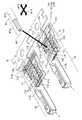
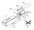
- FIG. 1 is a view for explaining a crimp terminal according to an embodiment of the present invention.
- the crimp terminal 1 in this embodiment is crimped to the end W1a of the covered electric wire W1 having the aluminum core wire W11 where the aluminum core wire W11 is exposed.
- the crimp terminal 1 includes a barrel portion 11, a terminal portion 12, and a seal member 14. In FIG. 1, two crimp terminals 1 are shown, but one crimp terminal 1 is shown with the seal member 14 removed so that the inner surface shape of the barrel portion 11 can be seen. .
- the barrel portion 11 and the terminal portion 12 are made from a metal plate such as a copper alloy by punching and sheet metal processing, and the surface thereof is subjected to tin plating or gold plating.
- the barrel part 11 and the terminal part 12 are arranged in a predetermined axial direction D11.
- the barrel part 11 and the terminal part 12 are collectively formed in a state where a plurality of the crimp terminals 1 are connected by the strip-like connecting piece 1a.
- the barrel portion 11 is a plate-like portion that is wound around the end portion W1a of the covered electric wire W1 so as to wrap the aluminum core wire W11 and the covered portion W12 in the circumferential direction.
- the barrel portion 11 is a core wire-covered integral barrel in which a portion that wraps the aluminum core wire W11 and a portion that wraps the covering portion W12 are integrated.
- the terminal portion 12 is a rectangular tubular female terminal that is connected to a pin terminal (not shown) to be connected.
- the barrel portion 11 has a bottom plate portion 111, an inner barrel piece 112, and an outer barrel piece 113.
- the bottom plate portion 111 is a portion extending in the axial direction D11.
- the inner barrel piece 112 and the outer barrel piece 113 are portions extending from the bottom plate portion 111 on both sides in the intersecting direction D12 intersecting the axial direction D11 in a plan view with respect to the bottom plate portion 111.
- the barrel portion 11 is wound around the end portion W1a with the inner barrel piece 112 on the inner side and the outer barrel piece 113 on the outer side at the time of crimping to the end portion W1a of the covered electric wire W1.
- each recess 114 is formed in a circular shape in plan view with respect to the inner surface 11 a of the barrel portion 11.
- the convex part 115 is formed in the bottom plate part 111 of the barrel part 11 by the press work from an outer surface side in the position where the aluminum core wire W11 in the edge part W1a of the covered electric wire W1 is mounted.
- a part of the plurality of concave portions 114 is also formed on the convex portion 115.
- a seal member 14 formed of an adhesive gel sheet is attached to the inner surface 11a of the barrel portion 11 so as to surround the plurality of concave portions 114 from three directions in plan view.
- the seal member 14 is affixed as follows.
- the adhesive gel sheet include, but are not limited to, those using an acrylic adhesive.
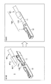
- FIG. 2 is a schematic diagram showing a state where the seal member shown in FIG. 1 is affixed to the inner surface of the barrel portion.
- the seal member 14 is formed of an adhesive gel sheet, and is arranged over three regions of the first region 11a-1, the second region 11a-2, and the third region 11a-3 on the inner surface 11a of the barrel part 11. Is done.
- the first region 11a-1 is a region that vertically cuts the outer barrel piece 113 in the axial direction D11.
- the second region 11a-2 is a region that crosses the inner surface 11a in the intersecting direction D12 near the terminal portion 12.
- the third region 11a-3 is a region that crosses the inner surface 11a in the intersecting direction D12 so as to intersect with the covering portion W12 of the end W1a.
- the seal member 14 is composed of three parts, a first seal part 141, a second seal part 142, and a third seal part 143.
- the first seal portion 141 is a portion that extends in a strip shape in the axial direction D11 in the first region 11a-1.
- the second seal portion 142 is a portion extending in a band shape in the intersecting direction D12 in the second region 11a-2.
- the third seal portion 143 is a portion extending in a strip shape in the intersecting direction D12 in the third region 11a-3.
- a groove 116 is formed on the inner surface 11a of the barrel portion 11 so as to overlap the seal member 14 in the first region 11a-1, the second region 11a-2, and the third region 11a-3. Yes.
- one groove 116 extends in the axial direction D11 while being bent in a sawtooth shape in the middle.
- one straight line extends in the intersecting direction D12
- in the third region 11a-3 three straight lines extend in the intersecting direction D12 and on the first region 11a-1 side. They are joining each other.
- the plurality of recesses 114 are provided avoiding the groove 116.
- the inner surface 11a of the barrel portion 11 is provided with a first indent portion 117a as a protrusion extending in the intersecting direction D12 at a position closer to the center than the third region 11a-3 in plan view. It has been. Further, a second indent portion 117b is provided as a protruding portion extending in the intersecting direction D12 at a position closer to the terminal portion 12 than the groove portion 116, which partially overlaps the second region 11a-2.
- the seal member 14 is affixed in a state of being divided in the middle of the path 11a-4 from the second area 11a-2 through the first area 11a-1 to the third area 11a-3. Specifically, the seal member 14 is affixed in a state where both the second seal portion 142 and the third seal portion 143 are separated from the first seal portion 141. Further, the second seal portion 142 is stuck in a state of being divided from the first seal portion 141 across the path 11a-4 in the axial direction D11. On the other hand, the third seal portion 143 is pasted in a state of being divided from the first seal portion 141 across the path 11a-4 in the intersecting direction D12. A slight gap G11 is opened between the second seal portion 142 and the first seal portion 141, and a slight gap G12 is opened between the third seal portion 143 and the first seal portion 141.
- the second seal portion 142 to be affixed to the second region 11a-2 of the seal member 14 is formed in a band shape with a wide width so that a part thereof is pushed out from the opening of the barrel portion 11 that becomes a cylindrical shape after the crimping. Is formed.
- the first seal portion 141 attached to the first region 11a-1 is narrower than the second seal portion 142, and has a shape corresponding to the groove 116 in the first region 11a-1.
- the first seal portion 141 is formed to have substantially the same width and substantially the same shape as the groove portion 116 so as to fit inside the groove portion 116.
- the third seal portion 143 attached to the third region 11a-3 is formed in a band shape slightly wider than the second seal portion 142.
- the first seal portion 141, the second seal portion 142, and the third seal portion 143 are overlapped with the grooves 116 of the first region 11a-1, the second region 11a-2, and the third region 11a-3, respectively. Affixed.
- the first seal portion 141 is affixed to fit inside the groove 116 as described above.
- the crimp terminal 1 described above is manufactured as follows.
- a sheet metal working step for forming a structure before the sealing member 14 is attached is performed.
- the barrel portion 11 is formed of a metal plate together with the terminal portion 12.
- the barrel portion 11 and the terminal portion 12 are formed together in a state where a plurality of the crimp terminals 1 are connected by the strip-like connecting piece 1a.
- formation of a plurality of concave portions 114, formation of the convex portions 115, and formation of the groove portions 116 on the inner surface 11a of the barrel portion 11 are also performed.
- This seal member affixing step is a step of affixing the seal member 14 in a state where it is divided along the path 11a-4 from the second region 11a-2 through the first region 11a-1 to the third region 11a-3. is there. That is, the first seal portion 141, the second seal portion 142, and the third seal portion 143 are individually attached to the inner surface 11 a of the barrel portion 11.
- the first seal portion 141, the second seal portion 142, and the third seal portion 143 are removed from the adhesive gel sheet and attached to the inner surface 11a of the barrel portion 11.
- the die cutting and sticking are performed almost simultaneously by pressing the pressure-sensitive adhesive gel sheet to the sticking place while punching the die toward the sticking place on the inner surface 11a of the barrel portion 11 with the die cutting cutter of each seal portion.
- the second seal portion 142 is stuck so as to overlap a part of the second indent portion 117b, and the third seal portion 143 is stuck so that the first indent portion 117a is exposed.
- the crimp terminal 1 manufactured in this way is crimped to the end W1a of the covered electric wire W1 by the following terminal connection method.
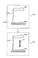
- FIG. 3 is a diagram showing a procedure for the crimping terminal shown in FIGS. 1 and 2 until preparation for crimping to the end of the covered electric wire is completed by the terminal connection method. It is a figure which shows the procedure until a crimp terminal is crimped
- FIG. 3 also shows a sheet metal working step (S11) and a seal member attaching step (S12) in the terminal manufacturing method described above.
- the barrel portion 11 and the terminal portion 12 are formed in the sheet metal processing step (S11), and the first seal portion 141, the second seal portion 142, and the third seal portion that form the seal member 14 in the seal member attaching step (S12). 143 is affixed.
- the crimp terminal 1 to be crimped is separated from the connecting piece 1a shown in FIG. And about the barrel part 11, curved deformation is performed as preparation for mounting the edge part W1a of the covered electric wire W1 (S13).
- the bending deformation is performed so that the inner barrel piece 112 and the outer barrel piece 113 are brought close to each other and the cross section intersecting the axial direction D11 is substantially U-shaped.
- a placing step of placing the end portion W1a of the covered wire W1 on the inner surface 11a of the barrel portion 11 after the bending deformation is performed as follows (S14).
- FIG. 5 is a diagram showing the mounting process shown in FIG. 4 in a plan view with respect to the inner surface of the barrel portion.
- the barrel portion 11 shown in a curved shape in FIG. It is shown in a state extended in a plane.
- the end of the aluminum core wire W11 at the end W1a overlaps the inner surface 11a of the barrel portion 11 along the axial direction D11 so that the second seal portion 142 of the seal member 14 overlaps the second seal portion 142.
- the part W1a is placed.
- the end portion W1a is placed on the inner surface 11a of the barrel portion 11 such that the tip W12a of the covering portion W12 overlaps the third seal portion 143 of the seal member 14.
- the exposed portion of the aluminum core wire W11 is placed so as to be in contact with the first indent portion 117a.
- the barrel portion 11 is wound around the end portion W1a so that the outer barrel piece 113 is overlapped with the inner barrel piece 112 inside.
- a crimping process for crimping is performed (S15).
- the terminal-attached electric wire TW1 in which the crimp terminal 1 is connected to the covered electric wire W1 is completed.
- the sealing member 14 seals each part of the crimping terminal 1 as follows to form the terminal-attached electric wire TW1.
- FIG. 6 is a diagram showing the electric wire with terminal after crimping, which is also shown in FIG.
- FIG. 7 is a diagram showing a change during the crimping process in the V11-V11 line cross section, the V12-V12 line cross section, and the V13-V13 line cross section in FIG.
- the first stage (S151) of the crimping process bending of the inner barrel piece 112 and the outer barrel piece 113 is started so as to wind around the aluminum core wire W11 on the convex portion 115 and the covering portion W12 in the vicinity thereof.
- the first seal portion 141 is in contact with the aluminum core wire W11
- the third seal portion 143 is in contact with the covering portion W12
- most of the second seal portion 142 is not substantially in contact with each other.
- the barrel portion 11 has a cylindrical shape. Then, the first seal portion 141 is sandwiched between the inner barrel piece 112 and the outer barrel piece 113, and the third seal portion 143 is stretched while being sandwiched between the covering portion W12 and the barrel portion 11. Go.
- the first seal portion 141 is formed in a width and shape corresponding to the groove portion 116, the amount of the seal member 14 sandwiched between the inner barrel piece 112 and the outer barrel piece 113 is small. Minimized. If the amount of the seal member 14 in this portion is too large, the outer barrel piece 113 is difficult to move with respect to the inner barrel piece 112 during winding, which may hinder crimping. On the other hand, in this embodiment, since the quantity of the sealing member 14 in this part is suppressed, such a hindrance by the sealing member 14 at the time of pressure bonding is suppressed.
- the edges of the plurality of recesses 114 bite into the aluminum core wire W11. Further, at this time, the strands of the aluminum core wire W11 are separated and expanded by the convex portions 115 located below the aluminum core wire W11, and the number of contacts between the barrel portion 11 and these strands increases. At the same time, the extension of the seal member 14 also proceeds.
- gaps G11 and G12 are opened between the second seal portion 142 and the third seal portion 143 and the first seal portion 141. These gaps G11 and G12 are closed by the extension of the sealing member 14 during pressure bonding.
- FIG. 8 is a schematic view showing a state in which the gap between the second seal portion and the third seal portion shown in FIG. 2 and the first seal portion is closed by the extension of the seal member at the time of pressure bonding.
- the second seal portion 142 is extended in the intersecting direction D12 that coincides with the length direction thereof.
- the second seal portion 142 is connected to the first seal portion 141, and the gap G11 between them is closed.
- sticker part 141 is extended in the axial direction D11 which corresponds to the length direction.
- the first seal portion 141 is connected to the third seal portion 143, and the gap G12 between them is closed.
- FIG. 9 is a side view of the electric wire with terminal shown in FIG. 6 as viewed in the direction of arrow V15 in the drawing
- FIG. 10 is a sectional view showing a cross section taken along line V14-V14 in FIG.
- the space between the inner barrel piece 112 and the outer barrel piece 113 is sealed by the first seal portion 141, and the opening 11 b on the terminal portion 12 side of the barrel portion 11 is sealed by the second seal portion 142. Sealed. Further, the space between the covering portion W12 and the barrel portion 11 is sealed by the third seal portion 143.
- the dimensions (hereinafter referred to as the crimp height CH11) of the terminal part 12 side (hereinafter referred to as the front end part 118) in the barrel part 11 after the crimping Is set to the following dimensions: That is, the crimp height CH11 of the front end portion 118 is crimped so as to be larger than the crimp height CH12 of the crimp portion 119 of the aluminum core wire W11.
- the second seal portion 142 located on the terminal portion 12 side of the seal member 14 is formed in a band shape with a width that allows a part to be pushed out from the opening 11b of the barrel portion 11 after crimping. Accordingly, as shown in FIG. 10, a part of the seal member 14 protrudes from the opening 11b of the front end portion 118 formed by the crimp height CH11 as described above. In other words, the crimp height CH11 of the front end portion 118 is set to a dimension that crushes the cylindrical barrel portion 11 to such an extent that the seal member 14 protrudes.
- the projection of the seal member 14 from the opening 11b seals the opening 11b of the barrel portion 11 at a high level. Moreover, a part of the sealing member 14 protrudes from between the covering part W12 and the barrel part 11 even on the extending side of the covered electric wire W1 in the barrel part 11, and seals the part at a high level. . On the other hand, a gap between the inner barrel piece 112 and the outer barrel piece 113 is sealed by a minimum amount of the first seal portion 141 formed in a width and shape corresponding to the groove 116. Thereby, sealing in various parts of the barrel portion 11 is performed while suppressing the obstruction of the crimping by the seal member 14.
- each part in the sealing member 14 is formed with a dimension that protrudes from the opening 11b of the barrel portion 11 and the extending side of the covered electric wire W1, so that these portions are surely sealed with the sealing member 14 after the crimping. This can be confirmed visually.
- crimp height of the aluminum core wire W11 is strengthened by making the crimp height CH12 of the crimping part 112 relatively small as described above, and the contact reliability with the crimping terminal 1 is improved.
- good continuity between the covered electric wire W1 and the crimp terminal 1 can be obtained by the edges of the concave portions 114 provided on the inner surface 11a of the barrel portion 11 by biting into the aluminum core wire W11. Then, the space between the inner barrel piece 112 and the outer barrel piece 113, the opening 11b on the terminal portion 12 side of the cylindrical barrel portion 11, and the space between the covering portion W12 and the barrel portion 11 are sealed after pressure bonding.
- a seal member 14 is affixed to the inner surface 11 a of the barrel portion 11.
- the second seal portion 142 attached to the second region 11a-2 of the seal member 14 is formed in a band shape with a width that allows a part of the seal member 14 to be pushed out from the opening 11b after crimping.
- the first seal portion 141 attached to the first region 11a-1 is formed in a width and shape corresponding to the groove 116.
- the sealing member 14 provides waterproofness to the contact portion with the aluminum core wire W11 over the entire periphery. In particular, the waterproofness of the opening 11b close to the aluminum core wire W11 is enhanced by the second seal portion 142 formed in a band shape with a width that is partially pushed out from the opening 11b after the crimping.
- the first seal portion 141 is formed to have a width and shape corresponding to the groove portion 116 of the first region 11a-1, so that the amount thereof is minimized, and the first seal portion 141 is wound with the inner barrel piece 112 inside.
- the hindrance by the seal member 14 when being pressed is suppressed.
- the groove 116 is also provided in the third region 11a-3 so as to extend in the intersecting direction D12.
- the groove 116 provided in the third region 11a-3 plays a role of suppressing the positional deviation of the third seal portion 143 at the time of pressure bonding, so that the manufacturing difficulty can be further alleviated.
- the groove 116 is provided in the second region 11a-2 so as to extend in the intersecting direction D11.
- the groove 116 of the second region 11a-1 plays a role of suppressing the positional deviation of the second seal portion 142 during crimping. The positional shift at the time is suppressed, and the manufacturing difficulty is further alleviated.
- the grooves 116 are provided in the third region 11a-3 so as to extend in three rows in the axial direction D11.
- the grooves 116 are provided in three rows in the third region 11a-3 that intersects with the covering portion W12 that is easy to move and apply force during crimping or the like.
- the positional deviation of the third seal portion 143 to be performed is further suppressed. Thereby, the difficulty in manufacture can be eased further.
- the end W1a of the covered wire W1 is placed on the inner surface 11a of the barrel portion 11 in the placement step (S14) as follows. Placed on. That is, the end W1a of the covered electric wire W1 is placed so that the tip W11a of the aluminum core wire W11 overlaps the second seal portion 142 of the seal member 14 near the terminal portion 12. As a result, the portion that is slightly disengaged from the second seal portion 142 in the axial direction D11 can immediately contribute to electrical conduction with the aluminum core wire W11. As a result, the electrical conductivity between the aluminum core wire W11 and the crimp terminal 1 can be improved. Is sufficiently secured. Thus, according to the terminal connection method of the present embodiment, sufficient electrical conductivity is ensured between the exposed aluminum core wire W11 and the crimp terminal 1 while ensuring waterproofness to the contact portion with the aluminum core wire W11. Can do.
- the placing step (S14) is a step of placing the end portion W1a on the inner surface 11a of the barrel portion 11 such that the tip W12a of the covering portion W12 overlaps the third seal portion 143. It has become. Thereby, about the axial direction D11, the part between the 2nd seal
- the first extension extending in the intersecting direction D12 at a position that does not overlap with the seal member 14 and is closer to the third region 11a-3.
- One indent portion 117a is provided.
- the barrel portion 11 is pressure-bonded to the end portion W1a of the covered electric wire W1 so that the aluminum core wire W11 contacts the first indent portion 117a.
- the first indent portion 117a extending in the intersecting direction D12 plays a role of resisting the return of the barrel portion 11 after crimping.
- the sealing member 14 made of a flexible adhesive gel overlaps with the first indent portion 117a and is wound around the end portion W1a, the sealing member 14 may behave as follows. That is, the portion that overlaps the first indent portion 117a may serve as a cushion at the time of crimping to increase the winding diameter of the first indent portion 117a and weaken the above-described role of the first indent portion 117a.
- the first indent portion 117a is directly in contact with the aluminum core wire W11 without the seal member 14 therebetween, by being crimped so that the aluminum core wire W11 contacts the first indent portion 117a. Wrapped. Accordingly, the first indent portion 117a can resist the return of the barrel portion 11 without being affected by the seal member 14. Moreover, since the 1st indent part 117a is wound without interposing the coating
- the return of the barrel portion 11 can be suppressed while ensuring the waterproof property for the contact portion with the aluminum core wire W11. Further, since the first indent portion 117a is in direct contact with the aluminum core wire W11, the electrical conductivity between the crimp terminal 1 and the aluminum core wire W11 can be sufficiently secured.
- the inner surface 11a of the barrel portion 11 has a second indent portion 117b extending in the intersecting direction D12 at a position closer to the terminal portion 12 as well. Is provided. Thereby, the return of the barrel part 11 can be satisfactorily suppressed both on the side closer to the terminal part 12 of the barrel part 11 and on the opposite side.
- the 1st indent part 117a and the 2nd indent part 117b which are obtained by sheet metal processing as a protrusion part of the inner surface 11a of the barrel part 11 are employ
- the indent portion has a strong resistance to the return as described above, so that the return of the barrel portion 11 can be suppressed more satisfactorily.
- the barrel portion 11 is formed on the end portion W1a so that the tip W12a of the covered portion W12 at the end portion W1a of the covered wire W1 overlaps the third seal portion 143. Crimped.
- the first indent portion 117a is provided as close to the third region 11a-3 as possible.
- the aluminum core wire W11 is brought into contact with the first indent portion 117a at such a position, and the return can be more effectively suppressed at a position close to the edge of the barrel portion 11.
- the end W1a is a barrel so that the aluminum core wire W11 is in contact with the first indent 117a. It is placed on the inner surface 11 a of the part 11.
- the return of the barrel part 11 can be suppressed favorably, without the 1st indent part 117a being influenced by the sealing member 14.
- the end portion W1a is placed on the inner surface 11a of the barrel portion 11 so that the tip W12a of the covering portion W12 overlaps the third seal portion 143. It is a process. Thus, as described above, it is possible to more effectively suppress the return at a position close to the edge of the barrel portion 11.
- the placing step (S14) places the end portion W1a on the inner surface 11a of the barrel portion 11 so that the tip W11a of the aluminum core wire W11 overlaps the second seal portion 142. It is a process.
- the conductivity between the aluminum core wire W11 and the crimp terminal 1 can be sufficiently secured.
- FIG. 11 is a diagram showing a first modification to the embodiment shown in FIGS.
- the same components as those shown in FIGS. 1 to 10 are denoted by the same reference numerals as those in FIGS. 1 to 10.
- these equivalent components will be described. Duplicate explanation is omitted. The same applies to the drawings referred to in other modified examples described later and the description of the modified examples.
- the crimp terminal 2 is crimped so that the same crimp height CH21 can be obtained at the front end portion 211 of the crimped barrel portion 21 and the crimp portion 212 of the aluminum core wire W11. Is done.
- seat member 14 is formed in strip
- FIG. 12 is a diagram showing a second modification of the embodiment shown in FIGS.
- the electric wire with terminal TWH2 of the second modified example is different from the above-described embodiment in the mounting state of the end portion W2a of the covered electric wire W2 on the inner surface 11a of the barrel portion 11. That is, in the second modification, the end W2a of the covered electric wire W2 is placed on the inner surface 11a of the barrel portion 11 so that the tip W21a of the aluminum core wire W21 is detached from the second seal portion 142 on the side opposite to the terminal portion 12. Placed. Furthermore, in this second modification, the end W2a of the covered wire W2 is placed on the inner surface 11a of the barrel portion 11 so that the tip W22a of the covered portion W22 is disengaged from the third seal portion 143 toward the terminal portion 12. The As a result, in the second modification, the crimp terminal 1 is crimped to the covered electric wire W2 so that the covered portion W22 is in contact with the first indent portion 117a.
- the embodiment described above can contribute to electrical conduction over a longer range in the inner surface 11a of the barrel portion 11 in the axial direction D11, and sufficiently ensure conductivity. What can be done is as described above.
- the winding diameter is suppressed by the thickness of the coating, and the return of the barrel portion 11 can be well suppressed. That's right.
- the second seal portion 142 is formed in a band shape with a width that is partially pushed out from the opening 11b of the barrel portion 11 after crimping, and the first seal portion 141 has a width corresponding to the groove portion 116. It is the same as embodiment mentioned above that it is formed in the shape. For this reason, it goes without saying that, similarly to the embodiment, in the second modified example, it is possible to alleviate the difficulty in manufacturing while ensuring the waterproof property for the contact portion with the aluminum core wire W21.
- FIG. 13 is a diagram showing a third modification of the embodiment shown in FIGS.
- the placing step of placing the end W1a of the covering portion W12 on the inner surface 31a of the barrel portion 31 is as follows. That is, in the placement step in the third modification, the end portion W1a is placed so that the covering portion W12 is in direct contact with the inner surface 31a of the barrel portion 31 between the seal member 14 and the end edge 31b of the barrel portion 31. It is a process.
- the tip W11a of the aluminum core wire W11 overlaps the second seal portion 142
- the tip W12a of the covering portion W12 overlaps the third seal portion 143
- the exposed portion of the aluminum core wire W11 is the first. It contacts the indented portion 117a.
- the second seal portion 142 is formed in a band shape with a width that is partially pushed out from the opening 11b of the barrel portion 11 after pressure bonding
- the first seal portion 141 is formed in a width and shape corresponding to the groove portion 116. This is also the same as the embodiment described above.
- the manufacturing difficulty can be alleviated while ensuring the waterproof property for the contact portion with the aluminum core wire W11.
- the point which can fully ensure electroconductivity, and the point which can suppress the return of the barrel part 31 favorably are the same as embodiment.
- the portion between the third seal portion 143 of the seal member 14 and the end edge 31b of the barrel portion 31 is in direct contact with the covering portion W12 and is crimped. Become. As a result, for example, it is possible to improve the fixing force of the barrel portion 31 to the covering portion W12 that is easy to move during use or the like and easily applied with force.
- FIG. 14 is a diagram showing a fourth modification of the embodiment shown in FIGS. 1 to 10, and FIG. 15 is a fifth modification of the embodiment shown in FIGS.
- FIG. 16 is a diagram showing a sixth modification of the embodiment shown in FIGS. 1 to 10. 14 to 16 show the crimp terminal in a state where the seal member is removed so that the groove portion in each modification can be seen.
- the groove portion 416a of the barrel portion 41 is provided in the first region 41a-1 and the third region 41a-3 on the inner surface 41a, and the second region 41a- 2 is not provided.
- the shape of the groove 416a in the first region 41a-1 and the third region 41a-3 is the same as that of the groove 116 in the above-described embodiment.
- the groove portion 416b of the barrel portion 41 is provided in the first region 41a-1 and the second region 41a-2 on the inner surface 41a, and the third region 41a- 3 is not provided except for the extension from the first region 41a-1.
- the shape of the groove 416b in the first region 41a-1 and the third region 41a-3 is the same as that of the groove 116 in the above-described embodiment.
- the groove portion 416c of the barrel portion 41 is provided in the first region 41a-1 on the inner surface 41a, but not in the second region 41a-2. . Further, the third region 41a-3 is not provided except for the extension from the first region 41a-1.
- the shape of the groove 416c in the first region 41a-1 is the same as the groove 116 in the above-described embodiment.
- the seal member 14 is affixed and crimped to the end W1a of the covered electric wire W1 in the same manner as in the above-described embodiment.
- manufacturing difficulty can be alleviated while securing waterproofness to the contact portion with the aluminum core wire W11.
- the point which can fully ensure electroconductivity and the point which can suppress the return of the barrel parts 41, 51, 61 favorably are the same as embodiment.
- FIG. 17 is a diagram showing a seventh modification of the embodiment shown in FIGS. 1 to 10, and FIG. 18 shows an eighth modification of the embodiment shown in FIGS.
- FIG. 19 is a diagram showing a ninth modification to the embodiment shown in FIGS.
- FIG. 20 is a diagram showing a tenth modification of the embodiment shown in FIGS. 1 to 10, and
- FIG. 21 is an eleventh modification of the embodiment shown in FIGS. FIG.
- the second seal portion 542a is divided from the first seal portion 541a, but the third seal portion 543a is connected to the first seal portion 541a.
- the shape of each seal portion is substantially the same as each seal portion of the seal member 14 in the above-described embodiment.
- the second seal portion 542a is extended in the intersecting direction D12 that coincides with the length direction at the time of pressure bonding. By this extension, the second seal portion 542a is connected to the first seal portion 541a, and the gap G11 between them is closed.
- the third seal portion 543b is divided from the first seal portion 541b, but the second seal portion 542b is connected to the first seal portion 541b.
- the shape of each seal portion is substantially the same as each seal portion of the seal member 14 in the above-described embodiment.
- the first seal portion 541b is extended in the axial direction D11 that coincides with the length direction at the time of pressure bonding. By this extension, the first seal portion 541b is connected to the third seal portion 543b, and the gap G12 between them is closed.
- the third seal portion 543c has the following shape. That is, the third seal portion 543c is formed in a width and shape corresponding to the groove 116 in the third region 11a-3 shown in FIG. Specifically, the third seal portion 543c is formed with substantially the same width and the same shape as the groove portion 116 so as to be accommodated in the groove portion 116. Both the second seal portion 542c and the third seal portion 543c are divided from the first seal portion 541c. The shapes of the first seal portion 541c and the second seal portion 542c are substantially the same as the seal member 14 in the above-described embodiment.
- the second seal portion 542c is extended in the intersecting direction D12 that coincides with the length direction at the time of pressure bonding.
- the second seal portion 542c is connected to the first seal portion 541c, and the gap G11 between them is closed.
- sticker part 541c is extended in the axial direction D11 which corresponds to the length direction.
- the first seal portion 541c is connected to the third seal portion 543c, and the gap G12 between them is closed.
- the seal member 54d in the tenth modification shown in FIG. 20 is a further modification of the seal member 54c in the ninth modification shown in FIG. That is, in the seal member 54d according to the tenth modification, the second seal portion 542d is divided from the first seal portion 541d, but the third seal portion 543d is connected to the first seal portion 541d. On the other hand, the shape of each seal portion is substantially the same as each seal portion of the seal member 54c in the ninth modification described above.
- the second seal portion 542d is extended in the intersecting direction D12 that coincides with the length direction at the time of pressure bonding. By this extension, the second seal portion 542d is connected to the first seal portion 541d, and the gap G11 between them is closed.
- the seal member 54e in the eleventh modification shown in FIG. 21 is also a further modification of the seal member 54c in the ninth modification shown in FIG. That is, in the seal member 54e in the eleventh modification, the third seal portion 543e is divided from the first seal portion 541e, but the second seal portion 542e is connected to the first seal portion 541e.
- the shape of each seal portion is substantially the same as each seal portion of the seal member 54c in the ninth modification described above.
- the first seal portion 541e is extended in the axial direction D11 that coincides with the length direction at the time of pressure bonding. By this extension, the first seal portion 541e is connected to the third seal portion 543e, and the gap G12 between them is closed.
- the seal members 54a, 54b, 54c, 54d, and 54e are attached to the barrel portion 11 and are crimped to the end portion W1a of the covered electric wire W1 as in the above-described embodiment. .
- manufacturing difficulty can be alleviated while securing waterproofness to the contact portion with the aluminum core wire W11.
- the point which can fully ensure electroconductivity and the point which can suppress the return of the barrel part 11 favorably are the same as embodiment.
- the ninth to eleventh modifications in which the third seal portions 543c, 543d, and 543e are formed in the width and shape corresponding to the groove 116 in the third region 11a-3 can further obtain the following advantages. It can. According to these ninth to eleventh modifications, the amount of the third seal portions 543c, 543d, and 543e is also minimized. As a result, sealing at various portions of the barrel portion 11 is performed while further hindering the crimping by the seal members 54c, 54d, and 54e, and manufacturing difficulties can be further alleviated.
- FIG. 22 is a view showing a twelfth modification of the embodiment shown in FIGS. 1 to 10, and FIG. 23 is a thirteenth modification of the embodiment shown in FIGS.
- FIG. 24 is a diagram showing a fourteenth modification to the embodiment shown in FIG. 1 to FIG.
- the recess 614a in the twelfth modification shown in FIG. 22 is formed in an elliptical shape in plan view. Further, the recess 614b in the thirteenth modification shown in FIG. 20 is formed in a parallelogram in plan view. Moreover, the recessed part 614c in the 14th modification shown by FIG. 21 is formed in the hexagon in planar view.
- modifications to the recess 114 in the crimp terminal 1 of the above-described embodiment include a triangular shape and other polygons in plan view.
- the resistance to the force to spread in the in-plane direction of the inner surface 11a is strong. .
- FIG. 25 shows a fifteenth modification of the embodiment shown in FIGS. 1 to 10, and FIG. 26 shows a sixteenth modification of the embodiment shown in FIGS.
- FIG. 27 is a diagram showing a seventeenth modification of the embodiment shown in FIGS. 1 to 10, and FIG. 28 is an eighteenth modification of the embodiment shown in FIGS. FIG.
- the first seal portion 741a is a portion extending in a strip shape in the axial direction D11 in the first region 11a-1.
- the second seal portion 742a is a portion extending in a band shape in the intersecting direction D12 in the second region 11a-2.
- the third seal portion 743a is a portion extending in a band shape in the intersecting direction D12 in the third region 11a-3.
- Each of the second seal portion 742a and the third seal portion 743a is divided from the first seal portion 741a by a gap G71a that crosses the path 11a-4 shown in FIG. 2 in the intersecting direction D12.
- the first seal portion 741a, the second seal portion 742a, and the third seal portion 743a are attached to the barrel portion 11 so as to overlap the groove portion 116.
- the first seal portion 741a is extended in the axial direction D11 that coincides with the length direction at the time of pressure bonding. By this extension, the first seal portion 741a is connected to both the second seal portion 742a and the third seal portion 743a, and the gap G71a is closed.
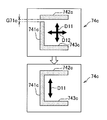
- the seal member 74b in the sixteenth modification shown in FIG. 26 is a further modification of the seal member 74a in the fifteenth modification shown in FIG. That is, in the seal member 74b according to the sixteenth modification, the second seal portion 742b is divided from the first seal portion 741b, but the third seal portion 743b is connected to the first seal portion 741b. In the sixteenth modification, the second seal portion 742b is divided from the first seal portion 741b and a gap G71b that crosses the path 11a-4 in the axial direction D11. In the seal member 74b according to the sixteenth modification, the second seal portion 742b is extended in the intersecting direction D12 that coincides with the length direction at the time of pressure bonding. By this extension, the second seal portion 742b is connected to the first seal portion 741b, and the gap G71b therebetween is closed.
- FIG. 27 is a further modification of the seal member 74b in the fifteenth modification shown in FIG. 25.
- the second seal portion 742c is divided from the first seal portion 741c by a gap G71c that crosses the path 11a-4 in the intersecting direction D12.
- the first seal portion 741c is extended in the axial direction D11 during pressure bonding. By this extension, the first seal portion 741c is connected to the second seal portion 742c, and the gap G71c therebetween is closed.
- the seal member 74d in the eighteenth modification shown in FIG. 25 is a further modification of the seal member 74b in the fifteenth modification shown in FIG. 25.
- the seal member 74d in the eighteenth modification shown in FIG. That is, in the seal member 74d according to the eighteenth modification, the third seal portion 743d is divided from the first seal portion 741d, but the second seal portion 742d is connected to the first seal portion 741d.
- the third seal portion 743d in the eighteenth modification is divided from the first seal portion 741d by a gap G71d that crosses the path 11a-4 in the axial direction D11.
- the third seal portion 743d extends in the intersecting direction D12 during pressure bonding. By this extension, the third seal portion 743d is connected to the first seal portion 741d, and the gap G71d therebetween is closed.
- the above-described embodiment is difficult to manufacture because the first seal portion 141 is formed in a width and shape corresponding to the groove 116 and the amount thereof is suppressed. As described above, this can be relaxed.
- a form in which a convex portion is provided on the barrel portion by pressing from the outer surface side is illustrated.
- the barrel portion is not limited to this form, and the convex portion may be omitted.
- a crimp terminal having the terminal portion 12 as a rectangular tubular female terminal is exemplified.
- a terminal part is not restricted to this, The specific shape and connection aspect are not ask
Abstract
アルミニウム芯線との接触部位に対する防水性を確保しつつも、製造上の困難さを緩和する。圧着端子(1)のバレル部(11)が、内バレル片(112)及び外バレル片(113)を有し、内面(11a)には、複数の凹部(114)が分散して設けられるとともに、外バレル片(113)の第1領域(11a-1)、端子部(12)寄りの第2領域(11a-2)、及び反対側の第3領域(11a-3)、に延在する溝部(116)が設けられ、粘着ジェルで形成されたシール部材(14)のうち第2シール部分(142)は、圧着後に一部が押し出される幅で帯状に形成され、第1シール部分(141)が、第2シール部分(142)よりも細幅で溝部(116)に応じた形状に形成されている。
Description
本発明は、アルミニウム芯線を有する被覆電線に圧着接続される圧着端子に関するものである。
近年、銅芯線を有する被覆電線に替えてアルミニウム芯線を有する被覆電線をワイヤハーネスに使用することが行われるようになってきている。このとき、例えばコネクタ端子等の圧着端子の中には、銅合金等で作製され、表面に錫メッキや金メッキが施されたものがある。このようなタイプの圧着端子を、被覆電線におけるアルミニウム芯線を露出させた端部に圧着すると、アルミニウム芯線と、圧着端子における圧着用のバレル部と、の間で異種金属の接触が生じることとなる。そして、このような接触部位に水分が付着すると、いわゆる異種金属腐食により、卑金属であるアルミニウムからなるアルミニウム芯線が腐食する恐れがある。
そこで、バレル部とアルミニウム芯線との接触部位の周囲をシール部材で囲んだ圧着端子が提案されている(例えば、特許文献1及び特許文献2参照。)。このようなタイプの圧着端子によれば、異種金属の接触部位への水分の浸入が防がれて、上記のような異種金属腐食の発生が回避される。
図29は、バレル部とアルミニウム芯線との接触部位の周囲をシール部材で囲んだ従来の圧着端子の一例を示す図である。
この図29に示されている圧着端子9は、銅合金等の金属板から板金加工によって作製され表面に錫メッキや金メッキが施された、バレル部91と、端子部92と、が所定の軸方向D91に配列されたものである。バレル部91は、アルミニウム芯線W91を有する被覆電線W9におけるアルミニウム芯線W91を露出させた端部W9aに巻き付けられて圧着される部位である。端子部92は、接続対象である不図示のピン端子と接続される雌型端子である。
バレル部91は、軸方向D91と交差する断面形状が略U字型となるように金属板が曲げられた構造となっている。このバレル部91の内面911に被覆電線W9の端部W9aが載置された後、バレル部91が端部W9aに巻き付けられて圧着される。バレル部91の内面911の一部が、端部W9aにおけるアルミニウム芯線W91との接触部位911aとなる。
接触部位911aには、この接触部位911aに対する平面視で軸方向D91と交差する交差方向D92に延びる溝が軸方向D91に複数列並べられたセレーション94が形成されている。バレル部91が端部W9aに巻き付けられて圧着されると、セレーション94をなす各溝の縁がアルミニウム芯線W91に食い込むことで、被覆電線W9と圧着端子9との良好な導通が得られる。
そして、この接触部位911aを囲むように、シール部材93が設けられている。バレル部91が端部W9aに巻き付けられて圧着されると、シール部材93が、接触部位911aの周囲における各所の間隙を密封して水分の浸入を防止する。
しかしながら、図29に一例が示されているような従来の圧着端子では、バレル部91に設けられたシール部材93が、バレル部91が端部W9aに巻き付けられて圧着される際の妨げとなる場合がある。
従って、本発明は、上記のような課題に着目し、アルミニウム芯線との接触部位に対する防水性を確保しつつも、製造上の困難さが緩和された圧着端子を提供することを目的とする。
上記課題を解決するために、本発明の圧着端子は、アルミニウム芯線を有する被覆電線における前記アルミニウム芯線を露出させた端部に巻き付けられて圧着されるバレル部と、接続対象と接続される端子部と、が所定の軸方向に配列された圧着端子であって、前記バレル部は、前記被覆電線の前記端部が載せられる、前記軸方向に延在する底板部と、当該底板部に対する平面視で前記軸方向と交差する交差方向の両側に前記底板部から延出した内バレル片及び外バレル片と、を有し、圧着時には前記内バレル片を内側にして前記端部に巻き付けられるものであり、前記バレル部の内面には、複数の凹部が分散して設けられるとともに、前記外バレル片を前記軸方向に縦断する第1領域、前記端子部寄りで前記内面を前記交差方向に横断する第2領域、及び前記端部の被覆部分と交差するように前記内面を前記交差方向に横断する第3領域、のうちの少なくとも前記第1領域を前記軸方向に延在する溝部が設けられ、粘着ジェルで形成されて、前記第1領域、前記第2領域、及び前記第3領域、に亘って貼付され、圧着後に、前記内バレル片と前記外バレル片との間と、筒状となる前記バレル部の前記端子部側の開口と、前記被覆部分と前記バレル部との間と、を密封するシール部材を備え、前記シール部材のうち前記第2領域に貼付される部分は、圧着後に前記開口から一部が押し出される幅で帯状に形成され、前記第1領域に貼付される部分が、前記第2領域に貼付される部分よりも細幅で前記溝部に応じた形状に形成されていることを特徴とする。
本発明の圧着端子では、圧着によって、バレル部の内面に設けられた各凹部の縁がアルミニウム芯線に食い込むことで被覆電線と圧着端子との良好な導通が得られる。そして、本発明の圧着端子では、粘着ジェルで形成されて、圧着後に、内バレル片と外バレル片との間と、筒状となるバレル部の端子部側の開口と、被覆部分とバレル部との間と、を密封するシール部材がバレル部の内面に貼付されている。ここで、本発明の圧着端子では、このシール部材のうち上記の第2領域に貼付される部分は、圧着後に開口から一部が押し出される幅で帯状に形成され、上記の第1領域に貼付される部分が、第2領域に貼付される部分よりも細幅で溝部に応じた形状に形成されている。シール部材によってアルミニウム芯線との接触部位に対する防水性が、その周囲全体に亘って得られる。特に、圧着後に開口から一部が押し出される幅で帯状に形成される部分によって、アルミニウム芯線に近い開口について防水性が高められている。そして、第1領域に貼付される部分が、第2領域に貼付される部分よりも細幅で溝部に応じた形状に形成されていることによって、その量が最小限に抑えられる。これにより、内バレル片を内側にして巻き付けられて圧着される際の、シール部材による妨げが抑えられる。このように、本発明の本発明の圧着端子によれば、アルミニウム芯線との接触部位に対する防水性を確保しつつも、製造上の困難さを緩和することができる。
ここで、本発明の圧着端子において、前記溝部が、前記第3領域にも前記交差方向に延在して設けられていることが好適である。
この好適な圧着端子によれば、第3領域に設けられた溝部が、シール部材のうちこの第3領域に貼付される部分の、圧着時の位置ずれを抑える役割を果たすことから、製造上の困難さを一層緩和することができる。
また、この好適な圧着端子において、前記シール部材のうち前記第3領域に貼付される部分も、前記第2領域に貼付される部分よりも細幅で前記溝部に応じた形状に形成されていることが一層好適である。
この一層好適な圧着端子によれば、第3領域に貼付される部分についても、その量が最小限に抑えられることから、製造上の困難さを更に緩和することができる。
また、第3領域に溝部が設けられた上記の好適な圧着端子において、前記溝部が、前記第3領域については、前記軸方向に複数列で延在するように設けられていることが一層好適である。
この一層好適な圧着端子によれば、例えば圧着等の際に動き易く力が掛かり易い被覆部分と交差する第3領域に、複数列に溝部が設けられているので、この第3領域に貼付されるシール部分の位置ずれが一層抑えられることとなる。これにより、製造上の困難さを一層緩和することができる。
本発明によれば、アルミニウム芯線との接触部位に対する防水性を確保しつつも、製造上の困難さが緩和された圧着端子を得ることができる。
以下、本発明の一実施形態について、適宜に変形例を交えながら説明する。
図1は、本発明の一実施形態にかかる圧着端子を説明するための図である。
本実施形態における圧着端子1は、アルミニウム芯線W11を有する被覆電線W1におけるアルミニウム芯線W11を露出させた端部W1aに圧着されるものである。圧着端子1は、バレル部11と、端子部12と、シール部材14と、を備えている。尚、図1では、圧着端子1が2つ示されているが、一方の圧着端子1については、バレル部11の内面形状が目視できるように、シール部材14を除いた状態で示されている。
バレル部11及び端子部12は、銅合金等の金属板から打抜き加工と板金加工によって作製され表面に錫メッキや金メッキが施される。バレル部11及び端子部12は、所定の軸方向D11に配列されている。ここで、本実施形態では、バレル部11及び端子部12は、帯板状の連結片1aで圧着端子1の複数個分が繋げられた状態でまとめて形成される。バレル部11は、被覆電線W1の端部W1aに、アルミニウム芯線W11と被覆部分W12とを周方向に包むように巻き付けられて圧着される板状の部位である。本実施形態では、このバレル部11は、アルミニウム芯線W11を包む部分と、被覆部分W12を包む部分と、が一体となった芯線-被覆一体バレルとなっている。端子部12は、接続対象である不図示のピン端子と接続される四角筒状の雌型端子である。
バレル部11は、底板部111と、内バレル片112と、外バレル片113と、を有している。底板部111は、上記の軸方向D11に延在する部位である。内バレル片112及び外バレル片113は、底板部111に対する平面視で軸方向D11と交差する交差方向D12の両側に底板部111から延出した部位である。バレル部11は、被覆電線W1の端部W1aへの圧着時には、後述するように内バレル片112を内側に、外バレル片113を外側にして端部W1aに巻き付けられる。
ここで、バレル部11の内面11aには、複数の凹部114が分散して設けられている。各凹部114は、バレル部11の内面11aに対する平面視で円形に形成されている。また、バレル部11の底板部111には、被覆電線W1の端部W1aにおけるアルミニウム芯線W11が載せられる位置に外面側からのプレス加工により凸部115が形成されている。複数の凹部114のうちの一部は、この凸部115上にも形成されている。
そして、バレル部11の内面11aには、複数の凹部114を平面視で三方から囲むように粘着ジェルシートで形成されたシール部材14が貼付されている。シール部材14は、次のように貼付されている。尚、粘着ジェルシートとしては、例えばアクリル系粘着剤を用いたもの等が挙げられるが、これに限定されるものではない。
図2は、図1に示されているシール部材がバレル部の内面に貼付される様子を示す模式図である。
シール部材14は、粘着ジェルシートで形成されて、バレル部11の内面11aにおける第1領域11a-1、第2領域11a-2、及び第3領域11a-3、の3つの領域に亘って配置される。第1領域11a-1は、外バレル片113を軸方向D11に縦断する領域である。第2領域11a-2は、端子部12寄りで内面11aを交差方向D12に横断する領域である。第3領域11a-3は、端部W1aの被覆部分W12と交差するように内面11aを交差方向D12に横断する領域である。
図1及び図2に示されているように、本実施形態では、シール部材14が、第1シール部分141と、第2シール部分142と、第3シール部分143と、の3つの部分からなる。第1シール部分141は、第1領域11a-1で軸方向D11に帯状に延在する部分である。第2シール部分142は、第2領域11a-2で交差方向D12に帯状に延在する部分である。第3シール部分143は、第3領域11a-3で交差方向D12に帯状に延在する部分である。
本実施形態では、バレル部11の内面11aには、第1領域11a-1、第2領域11a-2、及び第3領域11a-3に、シール部材14と重なるように溝部116が形成されている。溝部116は、第1領域11a-1では、中途で鋸歯状に曲折しつつ軸方向D11に1本が延びている。第2領域11a-2では、交差方向D12に直線状に1本が延びており、第3領域11a-3では、交差方向D12に直線状に3本が延びて第1領域11a-1側で互いに合流している。そして、複数の凹部114は、溝部116を避けて設けられている。
更に、本実施形態では、バレル部11の内面11aには、平面視で第3領域11a-3よりも中央寄りの位置に交差方向D12に延在する突条部として第1インデント部117aが設けられている。また、第2領域11a-2と部分的に重なる、溝部116よりは端子部12寄りの位置に交差方向D12に延在する突条部として第2インデント部117bが設けられている。
本実施形態では、シール部材14は、第2領域11a-2から第1領域11a-1を経て第3領域11a-3に至る経路11a-4の中途で分割された状態で貼付されている。具体的には、シール部材14が、第2シール部分142と第3シール部分143との両方が、第1シール部分141と分割された状態で貼付されている。また、第2シール部分142は、上記の経路11a-4を軸方向D11に横切って第1シール部分141と分割された状態で貼付されている。他方、第3シール部分143は、上記の経路11a-4を交差方向D12に横切って第1シール部分141と分割された状態で貼付されている。第2シール部分142と、第1シール部分141との間には若干の間隙G11が開き、第3シール部分143と、第1シール部分141との間には若干の間隙G12が開いている。
ここで、シール部材14のうち第2領域11a-2に貼付される第2シール部分142は、圧着後に筒状となるバレル部11の開口から一部が押し出されるように幅広の幅で帯状に形成されている。一方、第1領域11a-1に貼付される第1シール部分141は、第2シール部分142よりも細幅で、第1領域11a-1における溝部116に応じた形状に形成されている。具体的には、第1シール部分141は、溝部116の内部に収まるように、溝部116と略同幅及び略同形状に形成されている。また、第3領域11a-3に貼付される第3シール部分143は、第2シール部分142よりも若干幅広の帯状に形成されている。
第1シール部分141、第2シール部分142、及び第3シール部分143は、各々が第1領域11a-1、第2領域11a-2、及び第3領域11a-3の溝部116と重なるように貼付される。特に、第1シール部分141については、上記のように、溝部116の内部に収まるように貼付される。
以上に説明した圧着端子1は、次のように製造される。
まず、シール部材14の貼付前の構造物を形成する板金加工工程が行われる。板金加工工程では、バレル部11が、端子部12とともに金属板から形成される。上述したように、本実施形態では、この板金加工工程において、バレル部11及び端子部12が、帯板状の連結片1aで圧着端子1の複数個分が繋げられた状態でまとめて形成される。この板金加工工程では、バレル部11の内面11aにおける複数の凹部114の形成、凸部115の形成、及び溝部116の形成も行われる。
続いて、粘着ジェルシートでシール部材14を形成するとともに、シール部材14を、第1領域11a-1、第2領域11a-2、及び第3領域11a-3、に亘って貼付するシール部材貼付工程が行われる。このシール部材貼付工程は、第2領域11a-2から第1領域11a-1を経て第3領域11a-3に至る経路11a-4の中途で分割された状態でシール部材14を貼付する工程である。即ち、上記の第1シール部分141、第2シール部分142、及び第3シール部分143が個別にバレル部11の内面11aに貼付される。
また、シール部材貼付工程では、第1シール部分141、第2シール部分142、及び第3シール部分143について、粘着ジェルシートから型抜きされるとともに、バレル部11の内面11aに貼付される。各シール部分の型抜き用カッターで、バレル部11の内面11aにおける各貼付箇所に向かって粘着ジェルシートを型抜きつつ貼付箇所へと押し付けることで、型抜きと貼付とがほぼ同時に行われる。また、このとき、第2シール部分142は、第2インデント部117bの一部と重なるように貼付され、第3シール部分143は、第1インデント部117aが露出されるように貼付される。
このように製造された圧着端子1は、次のような端子接続方法によって、被覆電線W1の端部W1aに圧着される。
図3は、図1及び図2に示されている圧着端子について、端子接続方法によって被覆電線の端部に圧着するための準備が整うまでの手順を示す図であり、図4は、図3に示されている手順に続いて圧着端子が被覆電線の端部に圧着されるまでの手順を示す図である。
図3には、上述した端子製造方法における板金加工工程(S11)及びシール部材貼付工程(S12)も示されている。板金加工工程(S11)で、バレル部11及び端子部12が形成され、シール部材貼付工程(S12)で、シール部材14をなす第1シール部分141、第2シール部分142、及び第3シール部分143が貼付される。
被覆電線W1の端部W1aに圧着するに当たっては、まず、図1に示されている連結片1aから圧着対象の圧着端子1が切り離される。そして、そのバレル部11について、被覆電線W1の端部W1aを載せるための準備として、湾曲変形が行われる(S13)。この湾曲変形は、内バレル片112と外バレル片113とを互いに近づけて、軸方向D11と交差する断面が、略U字型となるように行われる。
続いて、湾曲変形後のバレル部11の内面11aに、被覆電線W1の端部W1aを載置する載置工程が次のように行われる(S14)。
図5は、図4に示されている載置工程を、バレル部の内面に対する平面視で示す図である。尚、この図5では、被覆電線W1の端部W1aと、バレル部11の内面11aにおける各部と、の位置関係を見易くするために、図4では湾曲形状で示されているバレル部11が、平面的に延ばされた状態で示されている。
載置工程(S14)では、シール部材14のうち第2シール部分142に、端部W1aにおけるアルミニウム芯線W11の先端W11aが重なるように、バレル部11の内面11aに、軸方向D11に沿って端部W1aが載置される。更に、この載置工程(S14)では、シール部材14のうち第3シール部分143に、被覆部分W12の先端W12aが重なるように、バレル部11の内面11aに端部W1aが載置される。また、この載置工程(S14)では、アルミニウム芯線W11の露出箇所が、第1インデント部117aに接するように載置される。
以上に説明した載置工程(S14)に続いて、図4に示されているように、内バレル片112を内側にして外バレル片113が重ねられるようにバレル部11を端部W1aに巻き付けて圧着する圧着工程が行われる(S15)。この圧着工程(S15)により、被覆電線W1に圧着端子1が接続された端子付き電線TW1が完成する。
ここで、上記の圧着工程(S15)では、シール部材14が、次のように圧着端子1の各所を密封して端子付き電線TW1が形作られる。
図6は、図4にも示されている圧着後の端子付き電線を示す図である。図7は、図6中のV11-V11線断面、V12-V12線断面、及びV13-V13線断面における、圧着工程中の変化を示す図である。
圧着工程の第1段階(S151)では、凸部115上のアルミニウム芯線W11と、その近傍の被覆部分W12とに巻き付くように内バレル片112と外バレル片113の曲げ加工が開始される。このとき、第1シール部分141がアルミニウム芯線W11に接し、第3シール部分143が被覆部分W12に接し、第2シール部分142の大部分は何れとも略接しないような位置関係となる。巻き付きが若干進んだ第2段階(S152)及び第3段階(S153)では、バレル部11が筒状となる。そして、第1シール部分141が内バレル片112と外バレル片113との間に挟まれ、第3シール部分143が被覆部分W12とバレル部11との間に挟まれた状態で延ばされていく。
このとき、本実施形態では、第1シール部分141が溝部116に応じた幅と形状に形成されているので、内バレル片112と外バレル片113との間に挟まれるシール部材14の量が最小限に抑えられる。この部分でのシール部材14の量が多過ぎると、巻き付けの際に内バレル片112に対して外バレル片113が動き難く圧着の妨げとなる場合がある。これに対し、本実施形態では、この部分でのシール部材14の量が抑えられるので、圧着時のシール部材14によるこのような妨げが抑えられる。
アルミニウム芯線W11等に圧力が掛かる第4段階(S154)、第5段階(S155)、及び第6段階(S156)で、アルミニウム芯線W11に、複数の凹部114の縁が食い込んでいく。また、このときには、アルミニウム芯線W11の下部に位置する凸部115によってアルミニウム芯線W11の素線がばらされて拡がり、バレル部11とこれらの素線との接触本数が増加する。同時にシール部材14の延びも進行する。
ここで、上述したように、本実施形態では、第2シール部分142及び第3シール部分143と、第1シール部分141との間には若干の間隙G11,G12が開いている。これらの間隙G11,G12が、圧着時の上記のシール部材14の延びにより塞がる。
図8は、図2に示されている第2シール部分及び第3シール部分と、第1シール部分との間の間隙が、圧着時のシール部材の延びにより塞がる様子を示す模式図である。
この図8に示されているように、圧着時には、第2シール部分142が、その長さ方向と一致する交差方向D12に延ばされる。この延びにより、第2シール部分142が、第1シール部分141と繋がり、両者間の間隙G11が塞がる。他方、第1シール部分141が、その長さ方向と一致する軸方向D11に延ばされる。この延びにより、第1シール部分141が、第3シール部分143と繋がり、両者間の間隙G12が塞がる。
次に、第6段階(S156)において、内バレル片112と外バレル片113との間と、筒状のバレル部11の端子部12側の開口11bと、被覆部分W12とバレル部11との間と、が延ばされたシール部材14によって密封される。
図9は、図6に示されている端子付き電線の、図中のV15矢視を示す側面図であり、図10は、図6中のV14-V14線断面を示す断面図である。
図10に示されているように、内バレル片112と外バレル片113との間は第1シール部分141によって密封され、バレル部11の端子部12側の開口11bは第2シール部分142によって密封される。また、被覆部分W12とバレル部11との間が第3シール部分143によって密封される。
ここで、本実施形態では、圧着において主として圧力が掛かる図10中上下方向について、圧着後のバレル部11における端子部12側(以後、前端部118と呼ぶ)の寸法(以後、クリンプハイトCH11と呼ぶ)が、次のような寸法に設定される。即ち、この前端部118のクリンプハイトCH11が、アルミニウム芯線W11の圧着部119のクリンプハイトCH12よりも大きくなるように圧着される。
このとき、シール部材14のうち端子部12側に位置する第2シール部分142は、上述したように、圧着後にバレル部11の開口11bから一部が押し出される幅で帯状に形成されている。これにより、上記のようなクリンプハイトCH11で形成された前端部118の開口11bからは、図10に示されているように、シール部材14の一部が突出する。言い換えると、前端部118のクリンプハイトCH11は、このようなシール部材14の突出が生じる程度に筒状のバレル部11を潰す寸法に設定される。
開口11bからのシール部材14の突出により、バレル部11の開口11bが高いレベルで密封されることとなっている。また、シール部材14の一部は、バレル部11における被覆電線W1の延出側においても、被覆部分W12とバレル部11との間から一部が突出して当該箇所を高いレベルで密封している。他方で、内バレル片112と外バレル片113との間は、溝部116に応じた幅と形状に形成された最小限の量の第1シール部分141によって密封される。これにより、シール部材14による圧着の妨げを抑えつつ、バレル部11の各所における密封が行われることとなる。
また、シール部材14における各部分を、バレル部11の開口11bや被覆電線W1の延出側から突出する寸法で形成することで、圧着後にこれらの箇所が確かにシール部材14で密封されていることを目視確認することが可能となっている。そして、圧着部112のクリンプハイトCH12を上記のように相対的に小さくすることで、アルミニウム芯線W11の圧着を強化し、圧着端子1との接触信頼性を向上させている。
以上に説明した実施形態では、圧着によってバレル部11の内面11aに設けられた各凹部114の縁がアルミニウム芯線W11に食い込むことで被覆電線W1と圧着端子1との良好な導通が得られる。そして、内バレル片112と外バレル片113との間と、筒状となるバレル部11の端子部12側の開口11bと、被覆部分W12とバレル部11との間と、を圧着後に密封するシール部材14がバレル部11の内面11aに貼付されている。ここで、本実施形態では、このシール部材14のうち上記の第2領域11a-2に貼付される第2シール部分142は、圧着後に開口11bから一部が押し出される幅で帯状に形成される。他方、上記の第1領域11a-1に貼付される第1シール部分141は、溝部116に応じた幅と形状に形成されている。シール部材14によってアルミニウム芯線W11との接触部位に対する防水性が、その周囲全体に亘って得られる。特に、圧着後に開口11bから一部が押し出される幅で帯状に形成される第2シール部分142によって、アルミニウム芯線W11に近い開口11bについて防水性が高められている。そして、第1シール部分141が、第1領域11a-1の溝部116に応じた幅と形状に形成されることによって、その量が最小限に抑えられ、内バレル片112を内側にして巻き付けられて圧着される際の、シール部材14による妨げが抑えられる。このように、本実施形態によれば、アルミニウム芯線W11との接触部位に対する防水性を確保しつつも、製造上の困難さを緩和することができる。
ここで、本実施形態では、溝部116が、第3領域11a-3にも交差方向D12に延在して設けられている。第3領域11a-3に設けられた溝部116が、第3シール部分143の、圧着時の位置ずれを抑える役割を果たすことから、製造上の困難さを一層緩和することができる。同様に、溝部116は、第2領域11a-2にも交差方向D11に延在して設けられている。この第2領域11a-1の溝部116が、第2シール部分142の、圧着時の位置ずれを抑える役割を果たすことから、本実施形態では、シール部材14の全ての貼付箇所に亘って、圧着時の位置ずれが抑えられ、製造上の困難さが一層緩和されたものとなっている。
また、本実施形態では、溝部116が、第3領域11a-3については、軸方向D11に3列で延在するように設けられている。これにより、例えば圧着等の際に動き易く力が掛かり易い被覆部分W12と交差する第3領域11a-3に、3列に溝部116が設けられているので、この第3領域11a-3に貼付される第3シール部分143の位置ずれが一層抑えられることとなる。これにより、製造上の困難さを一層緩和することができる。
また、図3~図4を参照して説明した本実施形態の端子接続方法では、上記の載置工程(S14)において、被覆電線W1の端部W1aがバレル部11の内面11aに次のように載置される。即ち、シール部材14のうち端子部12寄りの第2シール部分142にアルミニウム芯線W11の先端W11aが重なるように、被覆電線W1の端部W1aが載置される。これにより、第2シール部分142から軸方向D11に少しでも外れた部分が直ちにアルミニウム芯線W11との電気的な導通に寄与することができ、その結果、アルミニウム芯線W11と圧着端子1との導電性が十分に確保される。このように、本実施形態の端子接続方法によれば、アルミニウム芯線W11との接触部位に対する防水性を確保しつつも露出させたアルミニウム芯線W11と圧着端子1との導電性を十分に確保することができる。
ここで、本実施形態では、載置工程(S14)が、第3シール部分143に、被覆部分W12の先端W12aが重なるように、バレル部11の内面11aに端部W1aを載置する工程となっている。これにより、軸方向D11について、第2シール部分142と、第3シール部分143と、の間の部分が、略全長分に亘ってアルミニウム芯線W11との電気的な導通に寄与することとなる。これにより、露出させたアルミニウム芯線W11と圧着端子1との導電性を更に向上させることができる。
また、本実施形態の端子付き電線TW1では、図2に示されているように、シール部材14と重ならず且つ第3領域11a-3寄りとなる位置に、交差方向D12に延在する第1インデント部117aが設けられている。そして、図5に示されているように、この第1インデント部117aにアルミニウム芯線W11が接するように、被覆電線W1の端部W1aにバレル部11が圧着されている。
交差方向D12に延在する第1インデント部117aは、圧着後には、バレル部11の戻りに抵抗する役割を果たす。このとき、柔軟な粘着ジェルからなるシール部材14は、仮に第1インデント部117aと重なって端部W1aに巻き付けられると、次のように振る舞う場合がある。即ち、第1インデント部117aと重なった部分が、圧着時にクッションとなって第1インデント部117aでの巻き付き径を拡げて第1インデント部117aによる上記の役割を弱める働きをする場合がある。
しかしながら、本実施形態では、第1インデント部117aにアルミニウム芯線W11が接するように圧着されることで、第1インデント部117aが、間にシール部材14を介することなくアルミニウム芯線W11と直に接して巻き付けられる。これにより、第1インデント部117aは、シール部材14による影響を受けることなくバレル部11の戻りに抵抗することができる。また、第1インデント部117aは、間に被覆電線W1の被覆を介することもなく巻き付けられるので、巻き付き径が、この被覆の厚み分についても抑えられることとなり、この点においてもバレル部11の戻りに良好に抵抗することができる。その結果、バレル部11の戻りが良好に抑えられる。このように、本実施形態によれば、アルミニウム芯線W11との接触部位に対する防水性を確保しつつもバレル部11の戻りを抑えることができる。また、第1インデント部117aがアルミニウム芯線W11と直に接することにより、圧着端子1とアルミニウム芯線W11との導電性を十分に確保することもできる。
ここで、本実施形態では、図2に示されているように、バレル部11の内面11aには、端子部12寄りとなる位置にも、交差方向D12に延在する第2インデント部117bが設けられている。これにより、バレル部11の端子部12寄りと、その反対側と、の両方でバレル部11の戻りを良好に抑えることができる。
また、本実施形態では、バレル部11の内面11aの突状部として板金加工によって得られる第1インデント部117aや第2インデント部117bが採用されている。一般にインデント部は上記のような戻りに対する抵抗力が強いことから、バレル部11の戻りを更に良好に抑えることができる。
また、本実施形態では、図5に示されているように、被覆電線W1の端部W1aにおける被覆部分W12の先端W12aが第3シール部分143と重なるように、端部W1aにバレル部11が圧着される。これを見越して、本実施形態では、第1インデント部117aがなるべく第3領域11a-3に接近して設けられている。本実施形態によれば、このような位置の第1インデント部117aにアルミニウム芯線W11を接触させ、バレル部11の端縁に近い位置で、より効果的に戻りの抑制を行うことができる。
また、図3~図4を参照して説明した本実施形態の端子接続方法では、上記の載置工程(S14)において、第1インデント部117aにアルミニウム芯線W11が接するように端部W1aがバレル部11の内面11aに載置される。これにより、上述したように、第1インデント部117aがシール部材14の影響を受けることなくバレル部11の戻りを良好に抑えることができる。このように、本実施形態の端子接続方法によれば、アルミニウム芯線W11との接触部位に対する防水性を確保しつつもバレル部11の戻りを抑えることができる。
また、本実施形態の端子接続方法では、載置工程(S14)が、被覆部分W12の先端W12aが第3シール部分143と重なるように、バレル部11の内面11aに端部W1aを載置する工程となっている。これにより、バレル部11の端縁に近い位置で、より効果的に戻りの抑制を行うことができることも上述した通りである。
また、本実施形態の端子接続方法では、載置工程(S14)が、アルミニウム芯線W11の先端W11aが第2シール部分142と重なるように、バレル部11の内面11aに端部W1aを載置する工程となっている。これにより、アルミニウム芯線W11と圧着端子1との導電性を十分に確保することができることも上述した通りである。
次に、以上に説明した実施形態に対する各種変形例について説明する。
図11は、図1~図10に示されている実施形態に対する第1変形例を示す図である。尚、図11では、図1~図10に示されている構成要素と同等な構成要素については、図1~図10と同じ符号が付されており、以下では、これら同等な構成要素についての重複説明を省略する。このことは、後述の他の変形例で参照する図や、その変形例に対する説明においても同様とする。
この第1変形例の端子付き電線TWH1では、圧着端子2は、圧着後のバレル部21における前端部211とアルミニウム芯線W11の圧着部212とで、同程度のクリンプハイトCH21が得られるように圧着される。そして、シート部材14の第2シート部分142が、このときのクリンプハイトCH21で、開口11bから一部が押し出される幅で帯状に形成される。この第1変形例でも、最小限の量の第1シール部分141によってシール部材14による圧着の妨げを抑えつつ、密封に比較的多くの量を要する開口11bについては上記のような幅の第2シール部分142によって密封が行われることとなる。
図12は、図1~図10に示されている実施形態に対する第2変形例を示す図である。
この第2変形例の端子付き電線TWH2は、被覆電線W2の端部W2aの、バレル部11の内面11aへの載置状態が、上述した実施形態と異なっている。即ち、第2変形例では、アルミニウム芯線W21の先端W21aが、第2シール部分142から、端子部12とは反対側に外れるように、被覆電線W2の端部W2aがバレル部11の内面11aに載置される。更に、この第2変形例では、被覆部分W22の先端W22aが、第3シール部分143から端子部12寄りに外れるように、被覆電線W2の端部W2aがバレル部11の内面11aに載置される。この結果、第2変形例では、第1インデント部117aに被覆部分W22が接するように、圧着端子1が被覆電線W2に圧着される。
上述した実施形態は、この第2変形例と比較すると、軸方向D11について、バレル部11の内面11aにおけるより長い範囲に亘って電気的な導通に寄与させることができ、導電性を十分に確保できることは上述した通りである。また、上述した実施形態は、第1インデント部117aがアルミニウム芯線W11と直に接して巻き付けられることから被覆の厚み分巻き付き径が抑えられ、バレル部11の戻りを良好に抑えることができることも上述した通りである。
他方、この第2変形例でも、第2シール部分142は、圧着後にバレル部11の開口11bから一部が押し出される幅で帯状に形成され、第1シール部分141が、溝部116に応じた幅と形状に形成されていることは、上述した実施形態と同じである。このため、実施形態と同様に、この第2変形例でも、アルミニウム芯線W21との接触部位に対する防水性を確保しつつも、製造上の困難さを緩和できることは言うまでもない。
図13は、図1~図10に示されている実施形態に対する第3変形例を示す図である。
この第3変形例の端子付き電線TWH3では、圧着端子3において、シール部材14のうち第3シール部分143が、バレル部31の、被覆部分W12と交差する端縁31bから離れて配置されている。このため、この第3変形例の端子接続方法では、被覆部分W12の端部W1aをバレル部31の内面31aに載置する載置工程が次のような工程となっている。即ち、第3変形例における載置工程は、シール部材14とバレル部31の端縁31bとの間で被覆部分W12がバレル部31の内面31aと直に接するように端部W1aを載置する工程となっている。
他方で、上述した実施形態と同様に、アルミニウム芯線W11の先端W11aが第2シール部分142に重なり、被覆部分W12の先端W12aが第3シール部分143と重なり、アルミニウム芯線W11の露出箇所が第1インデント部117aに接する。また、第2シール部分142が、圧着後にバレル部11の開口11bから一部が押し出される幅で帯状に形成され、第1シール部分141が、溝部116に応じた幅と形状に形成されていることも、上述した実施形態と同じである。
この第3変形例によれば、上述した実施形態と同様に、アルミニウム芯線W11との接触部位に対する防水性を確保しつつも、製造上の困難さを緩和できることは言うまでもない。また、導電性を十分に確保できる点、バレル部31の戻りを良好に抑えることができる点も実施形態と同じである。
更に、この第3変形例によれば、シール部材14の第3シール部分143と、バレル部31の端縁31bと、の間の部分が、被覆部分W12と直に接して圧着されることとなる。これにより、例えば使用時等に動き易く力が掛かり易い被覆部分W12に対するバレル部31の固着力を向上させることができる。
次に、上述した実施形態に対する第4~第6変形例として、バレル部11における溝部116に対する3つの変形例について説明する。
図14は、図1~図10に示されている実施形態に対する第4変形例を示す図であり、図15は、図1~図10に示されている実施形態に対する第5変形例を示す図であり、図16は、図1~図10に示されている実施形態に対する第6変形例を示す図である。尚、これらの図14~図16では、各変形例における溝部が見えるように、シール部材が除かれた状態の圧着端子が示されている。
図14に示されている第4変形例における圧着端子4aでは、バレル部41の溝部416aが、内面41aにおける第1領域41a-1と第3領域41a-3に設けられ、第2領域41a-2には設けられていない。第1領域41a-1と第3領域41a-3における溝部416aの形状は、上述した実施形態における溝部116と同じである。
図15に示されている第5変形例における圧着端子4bでは、バレル部41の溝部416bが、内面41aにおける第1領域41a-1と第2領域41a-2に設けられ、第3領域41a-3については第1領域41a-1からの延長分を除いて設けられていない。第1領域41a-1と第3領域41a-3における溝部416bの形状は、上述した実施形態における溝部116と同じである。
図16に示されている第6変形例における圧着端子4cでは、バレル部41の溝部416cが、内面41aにおける第1領域41a-1に設けられ、第2領域41a-2には設けられていない。更に、第3領域41a-3については第1領域41a-1からの延長分を除いて設けられていない。第1領域41a-1における溝部416cの形状は、上述した実施形態における溝部116と同じである。
これら第4~第6変形例の何れについても、上述した実施形態と同様にシール部材14が貼付され、被覆電線W1の端部W1aに圧着される。その結果、この実施形態と同様に、アルミニウム芯線W11との接触部位に対する防水性を確保しつつも、製造上の困難さを緩和できることは言うまでもない。また、導電性を十分に確保できる点、バレル部41,51,61の戻りを良好に抑えることができる点も実施形態と同じである。
次に、上述した実施形態に対する第7~第11変形例として、シール部材14に対する5つの変形例について説明する。
図17は、図1~図10に示されている実施形態に対する第7変形例を示す図であり、図18は、図1~図10に示されている実施形態に対する第8変形例を示す図であり、図19は、図1~図10に示されている実施形態に対する第9変形例を示す図である。また、図20は、図1~図10に示されている実施形態に対する第10変形例を示す図であり、図21は、図1~図10に示されている実施形態に対する第11変形例を示す図である。
図17に示されている第7変形例におけるシール部材54aでは、第2シール部分542aが第1シール部分541aと分割されているが、第3シール部分543aが第1シール部分541aと繋がっている。各シール部分の形状は、上述した実施形態におけるシール部材14の各シール部分と略同じである。この第7変形例におけるシール部材54aでは、圧着時には、第2シール部分542aが、その長さ方向と一致する交差方向D12に延ばされる。この延びにより、第2シール部分542aが、第1シール部分541aと繋がり、両者間の間隙G11が塞がる。
図18に示されている第8変形例におけるシール部材54bでは、第3シール部分543bが第1シール部分541bと分割されているが、第2シール部分542bが第1シール部分541bと繋がっている。各シール部分の形状は、上述した実施形態におけるシール部材14の各シール部分と略同じである。この第8変形例におけるシール部材54bでは、圧着時には、第1シール部分541bが、その長さ方向と一致する軸方向D11に延ばされる。この延びにより、第1シール部分541bが、第3シール部分543bと繋がり、両者間の間隙G12が塞がる。
図19に示されている第9変形例におけるシール部材54cでは、第3シール部分543cが次のような形状となっている。即ち、この第3シール部分543cが、図2に示されている第3領域11a-3における溝部116に応じた幅と形状に形成されている。具体的には、第3シール部分543cは、この溝部116の内部に収まるように、溝部116と略同幅及び同形状で形成されている。そして、第2シール部分542c及び第3シール部分543cの双方が第1シール部分541cと分割されている。第1シール部分541c及び第2シール部分542cの形状は、上述した実施形態におけるシール部材14と略同じである。この第9変形例におけるシール部材54cでは、圧着時には、第2シール部分542cが、その長さ方向と一致する交差方向D12に延ばされる。この延びにより、第2シール部分542cが、第1シール部分541cと繋がり、両者間の間隙G11が塞がる。また、第1シール部分541cが、その長さ方向と一致する軸方向D11に延ばされる。この延びにより、第1シール部分541cが、第3シール部分543cと繋がり、両者間の間隙G12が塞がる。
図20に示されている第10変形例におけるシール部材54dは、図19に示されている第9変形例におけるシール部材54cの更なる変形例となっている。即ち、第10変形例におけるシール部材54dでは、第2シール部分542dが第1シール部分541dと分割されているが、第3シール部分543dが第1シール部分541dと繋がっている。一方で、各シール部分の形状は、上述した第9変形例におけるシール部材54cの各シール部分と略同じである。この第10変形例におけるシール部材54dでは、圧着時には、第2シール部分542dが、その長さ方向と一致する交差方向D12に延ばされる。この延びにより、第2シール部分542dが、第1シール部分541dと繋がり、両者間の間隙G11が塞がる。
図21に示されている第11変形例におけるシール部材54eも、図19に示されている第9変形例におけるシール部材54cの更なる変形例となっている。即ち、第11変形例におけるシール部材54eでは、第3シール部分543eが第1シール部分541eと分割されているが、第2シール部分542eが第1シール部分541eと繋がっている。一方で、各シール部分の形状は、上述した第9変形例におけるシール部材54cの各シール部分と略同じである。この第11変形例におけるシール部材54eでは、圧着時には、第1シール部分541eが、その長さ方向と一致する軸方向D11に延ばされる。この延びにより、第1シール部分541eが、第3シール部分543eと繋がり、両者間の間隙G12が塞がる。
これら第7~第11変形例の何れについても、上述した実施形態と同様にシール部材54a,54b,54c,54d,54eがバレル部11に貼付され、被覆電線W1の端部W1aに圧着される。その結果、この実施形態と同様に、アルミニウム芯線W11との接触部位に対する防水性を確保しつつも、製造上の困難さを緩和できることは言うまでもない。また、導電性を十分に確保できる点、バレル部11の戻りを良好に抑えることができる点も実施形態と同じである。
また、第3領域11a-3における溝部116に応じた幅と形状に第3シール部分543c,543d,543eが形成された第9~第11変形例については、更に、以下の利点を得ることができる。これら第9~第11変形例によれば、第3シール部分543c,543d,543eについても、その量が最小限に抑えられる。これにより、シール部材54c,54d,54eによる圧着の妨げを一層抑えつつ、バレル部11の各所における密封が行われることとなり、製造上の困難さを更に緩和することができる。
次に、上述した実施形態に対する第12~第14変形例として、バレル部11の内面11aに設けられる平面視で円形の凹部114に対する3つの変形例について説明する。
図22は、図1~図10に示されている実施形態に対する第12変形例を示す図であり、図23は、図1~図10に示されている実施形態に対する第13変形例を示す図であり、図24は、図1~図10に示されている実施形態に対する第14変形例を示す図である。
図22に示されている第12変形例における凹部614aは、平面視で楕円形に形成されたものである。また、図20に示されている第13変形例における凹部614bは、平面視で平行四辺形に形成されたものである。また、図21に示されている第14変形例における凹部614cは、平面視で六角形に形成されたものである。
上述した実施形態の圧着端子1における凹部114に対する変形例としては、この他にも平面視で三角形や他の多角形に形成された等が挙げられる。これら何れの変形例も、例えば従来セレーションとして採用されることがある交差方向D12に延在する直線状の溝と比較すれば、内面11aの面内方向に広げようとする力に対する抵抗力が強い。
次に、上述した実施形態に対する第15~第18変形例として、シール部材14に対する4つの変形例について説明する。
図25は、図1~図10に示されている実施形態に対する第15変形例を示す図であり、図26は、図1~図10に示されている実施形態に対する第16変形例を示す図である。また、図27は、図1~図10に示されている実施形態に対する第17変形例を示す図であり、図28は、図1~図10に示されている実施形態に対する第18変形例を示す図である。
図25に示されている第15変形例におけるシール部材74aでは、第1シール部分741aは、第1領域11a-1で軸方向D11に帯状に延在する部分である。第2シール部分742aは、第2領域11a-2で交差方向D12に帯状に延在する部分である。第3シール部分743aは、第3領域11a-3で交差方向D12に帯状に延在する部分である。そして、第2シール部分742aと第3シール部分743aとの両方が、第1シール部分741aと分割されている。また、第2シール部分742a及び第3シール部分743aは、何れも、図2に示されている経路11a-4を交差方向D12に横切る間隙G71aで第1シール部分741aと分割されている。第1シール部分741a、第2シール部分742a、及び第3シール部分743aが、溝部116と重なるようにバレル部11に貼付される。この第15変形例におけるシール部材74aでは、圧着時には、第1シール部分741aが、その長さ方向と一致する軸方向D11に延ばされる。この延びにより、第1シール部分741aが、第2シール部分742a及び第3シール部分743aの双方と繋がって間隙G71aが塞がる。
図26に示されている第16変形例におけるシール部材74bは、図25に示されている第15変形例におけるシール部材74aの更なる変形例となっている。即ち、第16変形例におけるシール部材74bでは、第2シール部分742bが第1シール部分741bと分割されているが、第3シール部分743bが第1シール部分741bと繋がっている。また、この第16変形例では、第2シール部分742bが第1シール部分741bと、上記の経路11a-4を軸方向D11に横切る間隙G71bで分割されている。この第16変形例におけるシール部材74bでは、圧着時には、第2シール部分742bが、その長さ方向と一致する交差方向D12に延ばされる。この延びにより、第2シール部分742bが、第1シール部分741bと繋がり、両者間の間隙G71bが塞がる。
図27に示されている第17変形例におけるシール部材74cも、図25に示されている第15変形例におけるシール部材74bの更なる変形例となっている。即ち、第17変形例におけるシール部材74cでは、第2シール部分742cが第1シール部分741cと分割されているが、第3シール部分743cが第1シール部分741cと繋がっている。また、この第17変形例では、第2シール部分742cが第1シール部分741cと、上記の経路11a-4を交差方向D12に横切る間隙G71cで分割されている。この第16変形例におけるシール部材74cでは、圧着時には、第1シール部分741cが軸方向D11に延ばされる。この延びにより、第1シール部分741cが、第2シール部分742cと繋がり、両者間の間隙G71cが塞がる。
図28に示されている第18変形例におけるシール部材74dも、図25に示されている第15変形例におけるシール部材74bの更なる変形例となっている。即ち、第18変形例におけるシール部材74dでは、第3シール部分743dが第1シール部分741dと分割されているが、第2シール部分742dが第1シール部分741dと繋がっている。また、この第18変形例では、第3シール部分743dが第1シール部分741dと、上記の経路11a-4を軸方向D11に横切る間隙G71dで分割されている。この第16変形例におけるシール部材74dでは、圧着時には、第3シール部分743dが交差方向D12に延ばされる。この延びにより、第3シール部分743dが、第1シール部分741dと繋がり、両者間の間隙G71dが塞がる。
上述した実施形態は、これら第15~第18変形例と比較すると、第1シール部分141が、溝部116に応じた幅と形状に形成されてその量が抑えられている分、製造上の困難さを緩和できることは上述した通りである。
他方、これら第15~第18変形例でも、例えば図5に示されているように被覆電線W1に圧着されることで、上述した実施形態と同様に、導電性を十分に確保でき、バレル部31の戻りを良好に抑えることができることは言うまでもない。
尚、以上に説明した実施形態は本発明の代表的な形態を示したに過ぎず、本発明は、この実施形態に限定されるものではない。即ち、本発明の骨子を逸脱しない範囲で種々変形して実施することができる。かかる変形によってもなお本発明の構成を具備する限り、勿論、本発明の範疇に含まれるものである。
例えば、上述した実施形態や各種変形例では、バレル部に、外面側からのプレス加工によって凸部が設けられた形態が例示されている。しかしながら、バレル部は、この形態に限るものではなく、この凸部に関しては省略してもよい。ただし、凸部を設けることで、アルミニウム芯線の素線をばらして拡げバレル部との接触本数を増加させることができることは上述した通りである。
また、上述した実施形態や各種変形例では、端子部の一例として、何れも、四角筒状の雌型端子としての端子部12を有する圧着端子が例示されている。しかしながら、端子部は、これに限るものではなく、その具体的な形状や接続態様を問うものではない。
1,2,3,4a,4b,4c圧着端子
11,21,31,41 バレル部
11a,31a,41a 内面
11a-1,41a-1 第1領域
11a-2,41a-2 第2領域
11a-3,41a-3 第3領域
11a-4,41a-4 経路
12 端子部
14,54a,54b,54c,54d,54e,74a,74b,74c,74d シール部材
111 底板部
112 内バレル片
113 外バレル片
114,614a,614b,614c 凹部
115 凸部
116,416a,416b,416c 溝部
117a 第1インデント部(突状部)
117b 第2インデント部(第2突条部)
141,541a,541b,541c,541d,541e,741a,741b,741c,741c 第1シール部分
142,542a,542b,542c,542d,542e,742a,742b,742c,742c 第2シール部分
143,543a,543b,543c,543d,543e,743a,743b,743c,743c 第3シール部分
D11 軸方向
D12 交差方向
G11,G12,G71a,G71b,G71c,G71d 間隙
W1 被覆電線
W1a 端部
W11 アルミニウム芯線
W11a 先端
W12 被覆部分
W12a 先端
TW1,TWH1,TWH2,TWH3 端子付き電線
Claims (3)
- アルミニウム芯線を有する被覆電線における前記アルミニウム芯線を露出させた端部に巻き付けられて圧着されるバレル部と、接続対象と接続される端子部と、が所定の軸方向に配列された圧着端子であって、
前記バレル部は、前記被覆電線の前記端部が載せられる、前記軸方向に延在する底板部と、当該底板部に対する平面視で前記軸方向と交差する交差方向の両側に前記底板部から延出した内バレル片及び外バレル片と、を有し、圧着時には前記内バレル片を内側にして前記端部に巻き付けられるものであり、
前記バレル部の内面には、複数の凹部が分散して設けられるとともに、前記外バレル片を前記軸方向に縦断する第1領域、前記端子部寄りで前記内面を前記交差方向に横断する第2領域、及び前記端部の被覆部分と交差するように前記内面を前記交差方向に横断する第3領域、のうちの少なくとも前記第1領域を前記軸方向に延在する溝部が設けられ、
粘着ジェルで形成されて、前記第1領域、前記第2領域、及び前記第3領域、に亘って貼付され、圧着後に、前記内バレル片と前記外バレル片との間と、筒状となる前記バレル部の前記端子部側の開口と、前記被覆部分と前記バレル部との間と、を密封するシール部材を備え、
前記シール部材のうち前記第2領域に貼付される部分は、圧着後に前記開口から一部が押し出される幅で帯状に形成され、前記第1領域に貼付される部分が、前記第2領域に貼付される部分よりも細幅で前記溝部に応じた形状に形成されていることを特徴とする圧着端子。 - 前記溝部が、前記第3領域にも前記交差方向に延在して設けられていることを特徴とする請求項1に記載の圧着端子。
- 前記シール部材のうち前記第3領域に貼付される部分も、前記第2領域に貼付される部分よりも細幅で前記溝部に応じた形状に形成されていることを特徴とする請求項2に記載の圧着端子。
Priority Applications (3)
| Application Number | Priority Date | Filing Date | Title |
|---|---|---|---|
| CN201780072934.8A CN109983626B (zh) | 2016-12-27 | 2017-04-26 | 压接端子 |
| EP17888689.1A EP3565063B1 (en) | 2016-12-27 | 2017-04-26 | Crimp terminal |
| US16/423,845 US10658784B2 (en) | 2016-12-27 | 2019-05-28 | Crimp terminal |
Applications Claiming Priority (2)
| Application Number | Priority Date | Filing Date | Title |
|---|---|---|---|
| JP2016253776A JP6886814B2 (ja) | 2016-12-27 | 2016-12-27 | 圧着端子 |
| JP2016-253776 | 2016-12-27 |
Related Child Applications (1)
| Application Number | Title | Priority Date | Filing Date |
|---|---|---|---|
| US16/423,845 Continuation-In-Part US10658784B2 (en) | 2016-12-27 | 2019-05-28 | Crimp terminal |
Publications (1)
| Publication Number | Publication Date |
|---|---|
| WO2018123099A1 true WO2018123099A1 (ja) | 2018-07-05 |
Family
ID=62707181
Family Applications (1)
| Application Number | Title | Priority Date | Filing Date |
|---|---|---|---|
| PCT/JP2017/016502 WO2018123099A1 (ja) | 2016-12-27 | 2017-04-26 | 圧着端子 |
Country Status (5)
| Country | Link |
|---|---|
| US (1) | US10658784B2 (ja) |
| EP (1) | EP3565063B1 (ja) |
| JP (1) | JP6886814B2 (ja) |
| CN (1) | CN109983626B (ja) |
| WO (1) | WO2018123099A1 (ja) |
Families Citing this family (4)
| Publication number | Priority date | Publication date | Assignee | Title |
|---|---|---|---|---|
| JP6803877B2 (ja) * | 2018-07-09 | 2020-12-23 | 矢崎総業株式会社 | 端子付き電線 |
| JP7305265B2 (ja) * | 2019-06-25 | 2023-07-10 | 矢崎総業株式会社 | 端子付き電線 |
| JP2021005455A (ja) * | 2019-06-25 | 2021-01-14 | 矢崎総業株式会社 | 端子付き電線 |
| US11264735B1 (en) * | 2020-08-28 | 2022-03-01 | TE Connectivity Services Gmbh | Electrical terminal for terminating a wide size range of magnet wires |
Citations (7)
| Publication number | Priority date | Publication date | Assignee | Title |
|---|---|---|---|---|
| JPS5940198B2 (ja) | 1977-04-12 | 1984-09-28 | 川研フアインケミカル株式会社 | 改良された固形洗剤 |
| JP3566541B2 (ja) * | 1998-03-31 | 2004-09-15 | 矢崎総業株式会社 | 防水コネクタ及び防水処理方法 |
| JP2009230998A (ja) * | 2008-03-21 | 2009-10-08 | Autonetworks Technologies Ltd | 端子金具付き電線の製造方法及び端子金具付き電線 |
| JP2012059438A (ja) * | 2010-09-07 | 2012-03-22 | Sumitomo Wiring Syst Ltd | 防水コネクタ |
| JP2012069449A (ja) * | 2010-09-27 | 2012-04-05 | Furukawa Electric Co Ltd:The | 圧着端子、接続構造体及びコネクタ |
| JP5480368B2 (ja) | 2010-03-30 | 2014-04-23 | 古河電気工業株式会社 | 圧着端子、接続構造体及びコネクタ |
| JP2015201269A (ja) * | 2014-04-04 | 2015-11-12 | 矢崎総業株式会社 | 圧着端子と電線の接続構造 |
Family Cites Families (17)
| Publication number | Priority date | Publication date | Assignee | Title |
|---|---|---|---|---|
| US3546366A (en) * | 1969-03-14 | 1970-12-08 | Itt | Compressible electrical connecters |
| JP5675205B2 (ja) * | 2010-08-05 | 2015-02-25 | 矢崎総業株式会社 | 圧着端子 |
| JP5882723B2 (ja) * | 2011-12-26 | 2016-03-09 | 矢崎総業株式会社 | 端子 |
| JP5953591B2 (ja) * | 2012-04-05 | 2016-07-20 | 矢崎総業株式会社 | 圧着端子を電線に圧着する方法 |
| JP6192947B2 (ja) * | 2013-02-20 | 2017-09-06 | 矢崎総業株式会社 | 端子金具付き電線 |
| JP6063788B2 (ja) * | 2013-03-19 | 2017-01-18 | 矢崎総業株式会社 | 端子金具及び端子付き電線の製造方法 |
| DE102013205235A1 (de) * | 2013-03-25 | 2014-09-25 | Tyco Electronics Amp Gmbh | Crimpverbindung |
| JP6265804B2 (ja) * | 2014-03-19 | 2018-01-24 | 矢崎総業株式会社 | 圧着端子と電線の接続構造 |
| JP5940198B2 (ja) | 2015-06-18 | 2016-06-29 | 古河電気工業株式会社 | 圧着端子、接続構造体及びコネクタ |
| JP6367785B2 (ja) * | 2015-12-16 | 2018-08-01 | 矢崎総業株式会社 | 端子付き電線及び端子圧着装置 |
| JP6307059B2 (ja) * | 2015-12-16 | 2018-04-04 | 矢崎総業株式会社 | 圧着端子 |
| JP6423333B2 (ja) * | 2015-12-16 | 2018-11-14 | 矢崎総業株式会社 | 圧着端子及び端子付き電線 |
| JP6279540B2 (ja) * | 2015-12-16 | 2018-02-14 | 矢崎総業株式会社 | 圧着端子 |
| JP2018037374A (ja) * | 2016-09-02 | 2018-03-08 | 矢崎総業株式会社 | 端子付き電線 |
| JP2018045762A (ja) * | 2016-09-12 | 2018-03-22 | 矢崎総業株式会社 | 圧着端子 |
| JP6543304B2 (ja) * | 2017-07-21 | 2019-07-10 | 矢崎総業株式会社 | 端子付き電線、端子圧着装置及び端子付き電線の製造方法 |
| JP2019029128A (ja) * | 2017-07-27 | 2019-02-21 | 矢崎総業株式会社 | 端子付き電線 |
-
2016
- 2016-12-27 JP JP2016253776A patent/JP6886814B2/ja active Active
-
2017
- 2017-04-26 WO PCT/JP2017/016502 patent/WO2018123099A1/ja unknown
- 2017-04-26 EP EP17888689.1A patent/EP3565063B1/en active Active
- 2017-04-26 CN CN201780072934.8A patent/CN109983626B/zh active Active
-
2019
- 2019-05-28 US US16/423,845 patent/US10658784B2/en active Active
Patent Citations (7)
| Publication number | Priority date | Publication date | Assignee | Title |
|---|---|---|---|---|
| JPS5940198B2 (ja) | 1977-04-12 | 1984-09-28 | 川研フアインケミカル株式会社 | 改良された固形洗剤 |
| JP3566541B2 (ja) * | 1998-03-31 | 2004-09-15 | 矢崎総業株式会社 | 防水コネクタ及び防水処理方法 |
| JP2009230998A (ja) * | 2008-03-21 | 2009-10-08 | Autonetworks Technologies Ltd | 端子金具付き電線の製造方法及び端子金具付き電線 |
| JP5480368B2 (ja) | 2010-03-30 | 2014-04-23 | 古河電気工業株式会社 | 圧着端子、接続構造体及びコネクタ |
| JP2012059438A (ja) * | 2010-09-07 | 2012-03-22 | Sumitomo Wiring Syst Ltd | 防水コネクタ |
| JP2012069449A (ja) * | 2010-09-27 | 2012-04-05 | Furukawa Electric Co Ltd:The | 圧着端子、接続構造体及びコネクタ |
| JP2015201269A (ja) * | 2014-04-04 | 2015-11-12 | 矢崎総業株式会社 | 圧着端子と電線の接続構造 |
Also Published As
| Publication number | Publication date |
|---|---|
| EP3565063B1 (en) | 2021-01-06 |
| CN109983626B (zh) | 2020-09-15 |
| US20190280422A1 (en) | 2019-09-12 |
| JP2018106997A (ja) | 2018-07-05 |
| EP3565063A4 (en) | 2019-12-25 |
| JP6886814B2 (ja) | 2021-06-16 |
| EP3565063A1 (en) | 2019-11-06 |
| US10658784B2 (en) | 2020-05-19 |
| CN109983626A (zh) | 2019-07-05 |
Similar Documents
| Publication | Publication Date | Title |
|---|---|---|
| WO2018123099A1 (ja) | 圧着端子 | |
| US10756449B2 (en) | Crimp terminal | |
| WO2018123098A1 (ja) | 端子接続方法 | |
| US10505287B2 (en) | Crimp terminal and crimp terminal manufacturing method | |
| US10573978B2 (en) | Crimp terminal with seal member | |
| JP2015041509A (ja) | 導電路及び電線 | |
| WO2018123097A1 (ja) | 端子付き電線および端子製造方法 | |
| JP2019106316A (ja) | 端子付電線 | |
| WO2015137191A1 (ja) | 電磁シールド部材 | |
| JP2015090741A (ja) | 圧着端子 |
Legal Events
| Date | Code | Title | Description |
|---|---|---|---|
| 121 | Ep: the epo has been informed by wipo that ep was designated in this application |
Ref document number: 17888689 Country of ref document: EP Kind code of ref document: A1 |
|
| NENP | Non-entry into the national phase |
Ref country code: DE |
|
| ENP | Entry into the national phase |
Ref document number: 2017888689 Country of ref document: EP Effective date: 20190729 |