WO2015137191A1 - 電磁シールド部材 - Google Patents
電磁シールド部材 Download PDFInfo
- Publication number
- WO2015137191A1 WO2015137191A1 PCT/JP2015/056170 JP2015056170W WO2015137191A1 WO 2015137191 A1 WO2015137191 A1 WO 2015137191A1 JP 2015056170 W JP2015056170 W JP 2015056170W WO 2015137191 A1 WO2015137191 A1 WO 2015137191A1
- Authority
- WO
- WIPO (PCT)
- Prior art keywords
- cut
- shield body
- shield
- reinforcing member
- electromagnetic shielding
- Prior art date
Links
Images


Classifications
-
- H—ELECTRICITY
- H05—ELECTRIC TECHNIQUES NOT OTHERWISE PROVIDED FOR
- H05K—PRINTED CIRCUITS; CASINGS OR CONSTRUCTIONAL DETAILS OF ELECTRIC APPARATUS; MANUFACTURE OF ASSEMBLAGES OF ELECTRICAL COMPONENTS
- H05K9/00—Screening of apparatus or components against electric or magnetic fields
- H05K9/0073—Shielding materials
- H05K9/0098—Shielding materials for shielding electrical cables
-
- B—PERFORMING OPERATIONS; TRANSPORTING
- B60—VEHICLES IN GENERAL
- B60R—VEHICLES, VEHICLE FITTINGS, OR VEHICLE PARTS, NOT OTHERWISE PROVIDED FOR
- B60R16/00—Electric or fluid circuits specially adapted for vehicles and not otherwise provided for; Arrangement of elements of electric or fluid circuits specially adapted for vehicles and not otherwise provided for
- B60R16/02—Electric or fluid circuits specially adapted for vehicles and not otherwise provided for; Arrangement of elements of electric or fluid circuits specially adapted for vehicles and not otherwise provided for electric constitutive elements
- B60R16/0207—Wire harnesses
- B60R16/0215—Protecting, fastening and routing means therefor
Definitions
- the present invention relates to an electromagnetic shielding member that shields electromagnetic noise.
- a shielded electric wire in a wire harness mounted on a vehicle, includes an electric wire to be shielded and an electromagnetic shielding member that collectively covers the electric wire.
- the electromagnetic shield member surrounds the electric wire and shields electromagnetic noise.
- the electromagnetic shielding member shown in Patent Document 1 is a member in which a thin metal plate is formed in a cylindrical shape.
- the electromagnetic shield member has a cut-off portion that is a cylindrical portion and a cut-forming portion in which a cut is formed along the direction from one end side to the other end side of the electromagnetic shield member.
- the cuts in the cut forming part are formed in parallel in the circumferential direction of the electromagnetic shield member.
- the cut non-forming portions and the cut forming portions are alternately formed along the longitudinal direction of the electromagnetic shield member.
- the cut forming part is a deformable part.
- the electromagnetic shielding member disclosed in Patent Document 1 can have a bent shape by deforming the cut forming portion.
- a crease that intersects the longitudinal direction of the electromagnetic shield member is formed in advance in the cut forming portion. In this case, the electromagnetic shield member is more easily bent.
- the electromagnetic shielding member disclosed in Patent Document 1 is made of a relatively thin metal plate. Therefore, for example, when the cut forming part of the electromagnetic shield member is bent with a relatively large curvature, the cut non-forming part adjacent to the deformed cut forming part is not greatly deformed into a flat shape. There is a desire to improve strength.
- An object of the present invention is to suppress deformation of a portion between cuts (no cut portion) in an electromagnetic shield member having a structure in which cuts arranged in the circumferential direction of a cylindrical metal member are formed.
- the electromagnetic shield member includes a shield body that forms a metal cylinder, and a sheet-like reinforcing member that is bonded to the shield body.
- the shield body has a cut forming part and a cut non-forming part.
- interruption formation part is a part in which the some 1st cut
- the cut non-forming portion is adjacent to the cut forming portion in the longitudinal direction.
- the reinforcing member has a cylindrical portion along at least one of the outer peripheral surface and the inner peripheral surface of the non-cut portion in the shield body and is bonded to the one surface.
- the electromagnetic shielding member according to the second aspect is an aspect of the electromagnetic shielding member according to the first aspect.
- the said shield body is a plate-shaped metal member bent in the cylinder shape.
- the electromagnetic shielding member according to the third aspect is an aspect of the electromagnetic shielding member according to the first aspect or the second aspect.
- the reinforcing member is a flexible member.
- the electromagnetic shielding member according to the fourth aspect is an aspect of the electromagnetic shielding member according to the third aspect.
- the said reinforcement member is formed in the cylinder shape which covers the said cut formation part and the said non-cut formation part in the said shield body.
- the reinforcing member is formed with a plurality of second cuts that overlap the first cuts in the cut forming portion.
- the said reinforcement member is adhere
- the electromagnetic shielding member according to the fifth aspect is an aspect of the electromagnetic shielding member according to the third aspect or the fourth aspect.
- the said reinforcement member is formed in the cylinder shape inside the range covering the said cut formation part and the said non-cut formation part in the said shield body.
- the reinforcing member is formed with a plurality of third cuts that overlap the first cuts in the cut forming portion.
- the said reinforcement member is adhere
- the electromagnetic shielding member according to the sixth aspect is an aspect of the electromagnetic shielding member according to the third aspect.
- the said reinforcement member is formed in the cylinder shape in the range covering the said cut formation part and the said non-cut formation part in the said shield body.
- the sheet-like reinforcing member is bonded to the surface of the non-cut portion at a cylindrical portion along at least one of the outer peripheral surface and the inner peripheral surface of the non-cut portion of the shield body.
- the non-cut portion is not easily deformed into a flat shape. This is because the strength of the reinforced non-cut portion is increased.
- This electromagnetic shielding member is particularly effective when an electric wire is wired along a curved path having a relatively large curvature.
- the shield body is a plate-like metal member bent into a cylindrical shape.
- the plate-like metal member can be retrofitted to the shielded electric wire by bending the plate-like metal member into a cylindrical shape so as to surround the shielded electric wire.
- the reinforcing member is a flexible member.
- the restoring force of the cylindrical portion in the reinforcing member resists stress that tends to deform the non-cut portion forming portion into a flat shape. That is, the deformation of the non-cut portion is suppressed by the restoring force of the reinforcing member.
- the reinforcing member is formed in a cylindrical shape covering the cut forming part and the non-cut forming part in the shield body.
- the reinforcing member is formed with a plurality of second cuts that overlap the first cuts in the cut forming portion.
- the reinforcement member is adhere
- each of the band-like portions between the plurality of second cuts in the flexible reinforcing member is easily bent according to the deformation of the cut forming part in the shield body, and does not hinder the deformation of the cut forming part.
- the non-cut portion can be reinforced without impairing the bending deformation of the cut forming portion of the shield body.
- the reinforcing member prevents contact between the shield body and a foreign object such as a stepping stone.
- a foreign object such as a stepping stone.
- wear of the shield body can be reduced.
- the reinforcing member is formed in a cylindrical shape inside the range extending from the cut forming portion and the non-cut forming portion in the shield body.
- the reinforcing member is formed with a plurality of third cuts that overlap the first cuts in the cut forming portion.
- the reinforcement member is adhere
- each of the band-shaped portions between the plurality of third cuts in the flexible reinforcing member is easily bent according to the deformation of the cut forming part in the shield body, and does not hinder the deformation of the cut forming part.
- the cut non-forming part can be reinforced without impairing the bending deformation of the cut forming part of the shield body.
- the reinforcing member is formed in a cylindrical shape in a range extending from the cut forming portion and the cut non-forming portion in the shield body.
- the electric wire is covered with the reinforcing member over the entire circumference. Therefore, it is possible to prevent foreign matter such as stepping stones from coming into contact with the electric wire and liquid such as water from being applied to the electric wire.
- FIG. 1 is a longitudinal sectional view of an electromagnetic shield member 1.
- FIG. 2 is a cross-sectional view of the electromagnetic shield member 1.
- FIG. 3 is a developed plan view of a shield body included in the electromagnetic shield member 1.
- FIG. It is a top view of a flat shield body.
- It is a schematic side perspective view of electromagnetic shielding member 1A concerning a 2nd embodiment.
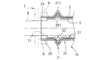
- It is a schematic longitudinal cross-sectional view of the electromagnetic shielding member 1A.
- It is a schematic side perspective view of the electromagnetic shielding member 1B which concerns on 3rd Embodiment.
- It is a schematic longitudinal cross-sectional view of the electromagnetic shielding member 1B.
- It is a longitudinal cross-sectional view of 1 C of electromagnetic shielding members which concern on 4th Embodiment.
- It is a cross-sectional view of 1 C of electromagnetic shielding members.
- the electromagnetic shielding member 1 includes a shield body 2 forming a metal cylinder and a reinforcing member 3 bonded to the shield body 2.
- the shield body 2 and the reinforcing member 3 are hatched with different patterns. Moreover, in FIG.2, 3,7,9,10, the adhesion part of the shield body 2 and the reinforcement member 3 is shown with the thick line thicker than another line.
- FIG. 1 is a side perspective view of the electromagnetic shielding member 1.
- FIG. 2 is a cross-sectional view of the electromagnetic shielding member 1 in the II-II plane of FIG. 3 is a cross-sectional view of the electromagnetic shielding member 1 in the III-III plane of FIG.
- FIG. 4 is an exploded plan view of the electromagnetic shield member 1 and shows a state in which the reinforcing member 3 is bonded to the flat metal plate 2X that is the base of the shield body 2.
- FIG. FIG. 5 is a developed plan view of the electromagnetic shield member 1 and shows a state after the reinforcing member 3 is bonded to the flat metal plate 2X that is the base of the shield body 2.
- the electromagnetic shielding member 1 is used in a state where the shielded electric wire 9 is passed through the hollow portion. 1 to 3, the electric wire 9 is indicated by a virtual line (two-dot chain line).
- the wire harness including the electric wire 9 and the electromagnetic shield member 1 surrounding the electric wire 9 is mounted on a vehicle such as an automobile, for example.
- the electromagnetic shield member 1 can be bent in the longitudinal direction when a cut forming portion 21 of the shield body 2 described later is deformed.
- the electromagnetic shielding member 1 in a bent state is indicated by a virtual line.
- the shield body 2 surrounds the three wires 9.
- the shield body 2 encloses the one electric wire 9
- the case where the two electric wires 9 are enclosed or the case where the four or more electric wires 9 are enclosed is also considered.
- the electric wire 9 is an insulated wire having, for example, a conductor mainly composed of copper or aluminum and an insulating coating covering the periphery of the conductor.
- the shield body 2 is a member formed by bending a thin plate-like metal member into a cylindrical shape.
- a metal member which comprises the shield body 2 lightweight and soft metals, such as aluminum, are employ
- the shield body 2 shown in FIGS. 1 to 3 forms a cylindrical body having a structure in which a flat metal plate 2X as shown in FIG. 4 is bent into a cylindrical shape.
- the shield body 2 is obtained by connecting a pair of edge portions 20X that form both ends of the metal plate 2X.
- the shield body 2 has a cut forming part 21 and a cut non-forming part 22.
- FIGS. 1 to 3 are cases where the shield body 2 has a plurality of cut forming portions 21 and non-cut forming portions 22, respectively.
- the shield body 2 is formed with the cut forming portions 21 and the cut non-forming portions 22 alternately in the longitudinal direction.
- interruption formation part 21 is formed only in one place is also considered.
- the cut forming portion 21 is a portion in which a plurality of first cuts 210 are formed side by side in parallel in the circumferential direction of the shield body 2.
- a plurality of first cuts 210 are formed at equal intervals in the circumferential direction in each cut forming portion 21.
- the plurality of first cuts 210 are cuts formed along the direction from one end side to the other end side in the longitudinal direction of the shield body 2.
- the example shown in FIG. 1 is an example where the first cut 210 is formed along the longitudinal direction of the shield body 2.
- the first cut 210 is a cut formed slightly obliquely with respect to the longitudinal direction of the shield body 2.
- the cut forming portion 21 is formed in a cylindrical shape in a state where both end surfaces 212 in the circumferential direction of the cut forming portion 21 are opposed to each other. Therefore, in the cylindrical cut forming portion 21, both end faces 212 are in a state that can be said to be substantially cut.
- first cuts 210 and one cut formed by both end faces 212 are formed at intervals that equally divide the entire circumferential direction into eight for each cut forming portion 21. This is an example.
- the number of cuts combining the first cut 210 and one cut formed by both end faces 212 is not limited to this.
- a part between each of the first cuts 210 and a part between one cut formed by both end faces 212 and the first cut 210 will be referred to as a partition part 211.
- This shield body 2 can be bent and deformed in the longitudinal direction by deforming the plurality of partition portions 211 in the cut forming portion 21.
- each of the partition portions 211 of the cut forming portion 21 has a shape protruding toward the outer peripheral surface side of the shield body 2.
- each of the partition portions 211 is bent into a curved shape projecting toward the outer peripheral surface side of the shield body 2 at the central portion in the longitudinal direction of the first cut 210.
- each of the first cuts 210 is in an open state.
- the partition part 211 is easily deformed. That is, the electromagnetic shield member 1 is easily bent at the cut forming portion 21.
- the cut non-forming portion 22 is adjacent to the cut forming portion 21 in the longitudinal direction of the shield body 2.
- the cut non-forming portion 22 is a cylindrical portion in which the first cut 210 is not formed.
- the non-cut portion 22 has a connecting portion 221 in which the edge portion 20X of the metal plate 2X overlaps and is connected.
- the connecting portion 221 is a portion where the edge portions 20 ⁇ / b> X of the metal plate 2 ⁇ / b> X are bonded and joined together.
- the edge parts 20X of the metal plate 2X are connected by crimping
- a plurality of creases 5 along the longitudinal direction of the shield body 2 are formed side by side in the circumferential direction of the non-cut portion 22.
- the crease 5 is formed by longitudinally cutting each cut non-forming portion 22 at the same position as each cut forming portion 21 in the circumferential direction of the shield body 2.
- FIG. 1 is an example in which seven fold lines 5 formed by cutting the shield body 2 vertically are formed in the non-cut portion 22.
- the non-cut portion 22 is not easily deformed when the shield body 2 is bent.
- the crease 5 is not formed in the cut non-formation part 22 is also considered.
- the contour shape of the non-cut portion 22 is a perfect circle, an ellipse, an oval (rounded rectangle), or the like.
- the reinforcing member 3 is a sheet-like member bonded to the shield body 2.
- the reinforcing member 3 is bonded to the shield body 2 in a state of being bent into a cylindrical shape.
- the reinforcing member 3 has a cylindrical portion along the outer peripheral surface of the non-cut portion 22 in the shield body 2, and the cylindrical portion is the outer periphery of the non-cut portion 22. Bonded to the surface.
- the reinforcing member 3 further has a cylindrical portion that covers the cut forming portion 21 in the shield body 2.
- the reinforcing member 3 is a member (flexible member) that can be bent and deformed.
- the reinforcing member 3 is a flexible film such as a thin and light laminate film or an elastic member such as a rubber-based resin.
- the reinforcing member 3 is formed with a plurality of second cuts 320 that overlap each of the first cuts 210 in the cut forming part 21 of the shield body 2.
- the partition part 321 that is a portion between the adjacent second cuts 320 in the reinforcing member 3 is bonded to the outer peripheral surface of the partition part 211 in the cut forming part 21.
- first reinforcing portion 31 a portion of the reinforcing member 3 bonded to the outer peripheral surface of the non-cut portion 22 is referred to as a first reinforcing portion 31. Further, the portion where the second cut 320 is formed in the reinforcing member 3 is referred to as a second reinforcing portion 32.
- the 1st reinforcement part 31 in the reinforcement member 3 is a part which prevents that the cut
- the first reinforcing portion 31 of the reinforcing member 3 is bonded to the outer peripheral surface of the non-cut portion 22 and is formed in a cylindrical shape.
- the reinforcing member 3 is a flexible member. Therefore, the 1st reinforcement part 31 in the reinforcement member 3 has the restoring force which tries to maintain a cylindrical shape with respect to the stress which is going to deform
- the first reinforcing portion 31 Due to the restoring force of the reinforcing member 3, the first reinforcing portion 31 is not easily deformed into a flat shape. At this time, the non-cut portion 22 in the shield body 2 to which the first reinforcing portion 31 is bonded is also difficult to deform into a flat shape.
- the second reinforcing portion 32 in the reinforcing member 3 is a portion that improves the strength of the cut forming portion 21 in the shield body 2.
- the partition part 321 in the second reinforcing part 32 of the reinforcing member 3 is bonded to the outer peripheral surface of the partition part 211 of the cut forming part 21 of the shield body 2.
- the portions that are deformed when the electromagnetic shield member 1 is bent are the partition portion 211 of the cut forming portion 21 of the shield body 2 and the partition portion 321 of the reinforcing member 3 bonded to the partition portion 211.
- the thickness of the entire deformed portion of the electromagnetic shield member 1 that is deformed when the electromagnetic shield member 1 is bent is increased, and the strength of the deformed portion is improved.
- the reinforcing member 3 is a flexible member, the reinforcing member 3 does not hinder the deformation of the cut forming portion 21 of the shield body 2.
- the first cut 210 in the shield body 2 and the second cut 320 in the reinforcing member 3 are made at the same time, for example, when the sheet-like reinforcing member 3 is attached to the metal plate 2X.
- an example of manufacturing the electromagnetic shielding member 1 will be described with reference to FIGS.
- the reinforcing member 3 is bonded to the metal plate 2X.
- the reinforcing member 3 is bonded to the entire surface of the metal plate 2X.
- a crease 5 formed by pressing or the like is formed on the metal plate 2X before the reinforcing member 3 is bonded.
- the metal plate 2X after the reinforcing member 3 is bonded is provided with a crease 5 by pressing or the like.
- the cylindrical shield body 2 in which the reinforcing member 3 is bonded to the outer peripheral surface is obtained by bonding in a state where the edges 20X of the metal plate 2X overlap. be able to.
- the portion between the first cut 210 of the metal plate 2X (partition portion 211) and the second cut 320 in the reinforcing member 3 After the portion (partition portion 321) is bent into a curved shape, the metal plate 2X and the reinforcing member 3 are bent into a cylindrical shape. Thereby, the electromagnetic shielding member 1 shown by FIG. 1 is obtained.
- the sheet-like reinforcing member 3 is bonded to the surface of the non-cut portion 22 at a cylindrical portion along the outer peripheral surface of the non-cut portion 22 in the shield body 2.
- the non-cut portion 22 is not easily deformed into a flat shape. This is because the strength of the reinforced non-cut portion 22 is increased.
- the electromagnetic shielding member 1 is particularly effective when the electric wire 9 is wired along a curved path having a relatively large curvature.
- the shield body 2 is a plate-like metal member (metal plate 2X) bent into a cylindrical shape.
- the metal plate 2X can be retrofitted to the shielded electric wire 9 by bending the metal plate 2X into a cylindrical shape so as to surround the shielded electric wire 9.
- the reinforcing member 3 is a flexible member.
- the restoring force of the cylindrical portion in the reinforcing member 3 resists the stress that tends to deform the non-cut portion 22 into a flat shape. That is, the deformation of the non-cut portion 22 is suppressed by the restoring force of the reinforcing member 3.
- the reinforcing member 3 is formed in a cylindrical shape that covers the cut forming part 21 and the cut non-forming part 22 in the shield body 2.
- the reinforcing member 3 is formed with a plurality of second cuts 320 that overlap the first cuts 210 in the cut forming part 21.
- the reinforcing member 3 is bonded to the outer peripheral surface of the non-cut portion 22 and the portion (partition portion 211) between the first cuts 210 on the outer peripheral surface of each of the cut forming portions 21.
- each partition part 321 between the plurality of second cuts 320 in the flexible reinforcing member 3 is easily bent according to the deformation of the cut forming part 21 in the shield body, and does not hinder the deformation of the cut forming part 21. .
- the cut non-forming part 22 can be reinforced without impairing the bending deformation of the cut forming part 21 of the shield body 2.
- the reinforcing member 3 prevents contact between a foreign object such as a stepping stone and the shield body 2. As a result, it is possible to reduce abnormal noise caused by contact between the shield body 2 that is a metal member and a foreign object. Further, the wear of the shield body 2 can be reduced.
- FIG. 6 is a schematic side perspective view of the electromagnetic shielding member 1A.
- FIG. 7 is a cross-sectional view of the end portion of the electromagnetic shield member 1A in the IV-IV plane of FIG.
- the electromagnetic shield member 1 ⁇ / b> A is different from the first embodiment in that the reinforcing member 3 is bonded to the inside of the shield body 2. 6 and 7, the same components as those shown in FIGS. 1 to 5 are given the same reference numerals. Hereinafter, differences from the first embodiment will be described.
- the reinforcing member 3 is formed in a cylindrical shape inside the range extending over the cut forming portion 21 and the cut non-forming portion 22 in the shield body 2.
- the reinforcing member 3 is formed with a plurality of third cuts 330 that overlap the first cuts 210 in the cut forming part 21.
- one of the plurality of third cuts 330 also overlaps one cut formed by both end faces 212.
- the partition part 331 which is a strip-shaped part between the adjacent third cuts 330 in the reinforcing member 3 is bonded to the inner side surface of the partition part 211 in the cut forming part 21. That is, in the present embodiment, the reinforcing member 3 is bonded to the inner peripheral surface of the non-cut portion 22 and the portion (partition portion 211) between the first cuts 210 in each of the cut portions 21.
- the non-cut portion 22 of the shield body 2 is not easily deformed into a flat shape by the first reinforcing portion 31 of the reinforcing member 3 bonded to this portion.
- each of the partition portions 331 which are band-like portions between the plurality of third cuts 330 in the flexible reinforcing member 3 is easily bent in accordance with the deformation of the partition portion 211 of the cut forming portion 21 in the shield body 2.
- the deformation of the cut forming part 21 is not hindered.
- the cut non-forming portion 22 can be reinforced without impairing the bending deformation of the cut forming portion 21 of the shield body 2 as in the first embodiment.
- the positions of the end of the reinforcing member 3 and the end of the shield body 2 do not match.
- the end of the reinforcing member 3 exists at a position where a part from the end of the shield body 2 is left behind.
- the conducting portion 25 which is a portion where the reinforcing member 3 is not bonded to the inner side surface of the shield body 2 of the electromagnetic shield member 1A is connected to, for example, a cylindrical shield connecting portion 71 in the shield shell member 7.
- the shield shell member 7 is a metal member that is connected to a housing that houses the electrical equipment to which the electric wire 9 to be shielded is connected. In FIG. 7, the shield shell member 7 is indicated by a virtual line (two-dot chain line).
- the conducting portion 25 of the electromagnetic shield member 1A is put on the shield connecting portion 71 of the shield shell member 7.
- the caulking member 8 such as the caulking ring or the caulking band is caulked from the outer periphery of the conducting portion 25 of the electromagnetic shielding member 1A.
- the electromagnetic shielding member 1A of the present embodiment is obtained by bending the reinforcing member 3 and the metal plate 2X, which are bonded to portions other than the edge 20X in the metal plate 2X, into a cylindrical shape.
- the electromagnetic shield member 1A may be a member obtained by bending the reinforcing member 3 bonded to the entire surface of the metal plate 2X and the metal plate 2X into a cylindrical shape.
- FIG. 8 is a schematic side perspective view of the electromagnetic shielding member 1B.
- FIG. 9 is a cross-sectional view of the end portion of the electromagnetic shield member 1B in the VV plane of FIG.
- the electromagnetic shield member 1B is different from the first embodiment in that the second cut 320 is not formed in the reinforcing member 3. Further, the electromagnetic shield member 1B is different from the second embodiment in that the third cut 330 is not formed in the reinforcing member 3. 8 and 9, the same components as those shown in FIGS. 1 to 7 are given the same reference numerals.
- differences from the first embodiment and the second embodiment will be described.
- the reinforcing member 3 is formed in a cylindrical shape in a range extending from the inside of the shield body 2 to the cut forming portion 21 and the cut non-forming portion 22 in the shield body 2.
- the reinforcing member 3 is bonded to the inner peripheral surface of the cut non-forming portion 22 of the shield body 2, but is not bonded to the inner peripheral surface of the cut forming portion 21.
- the non-cut portion 22 of the shield body 2 is not easily deformed into a flat shape by the first reinforcing portion 31 of the reinforcing member 3 bonded to this portion.
- the reinforcing member 3 does not interfere with the deformation of the cut forming portion 21 of the shield body 2. This is because the inner surface of the partition part 211 in the shield body 2 and the outer peripheral surface of the reinforcing member 3 are not bonded.
- the positions of the end of the reinforcing member 3 and the end of the shield body 2 do not match. This is because it is necessary to achieve conduction between the shield body 2 of the electromagnetic shield member 1B and the shield shell member 7.
- the electric wire 9 inserted into the electromagnetic shield member 1B is covered over the entire circumference by the shield body 2 and the reinforcing member 3. In this case, it is possible to prevent foreign matters such as stepping stones from coming into contact with the electric wire 9 and liquid such as water from being applied to the electric wire 9.
- FIG. 10 is a longitudinal sectional view of the electromagnetic shielding member 1C.
- FIG. 11 is a cross-sectional view of the electromagnetic shielding member 1C in the VI-VI plane of FIG. 10 and 11, the same components as those shown in FIGS. 1 to 9 are given the same reference numerals.
- the electromagnetic shielding member 1C is different from the first embodiment in that the second cut 320 is not formed in the reinforcing member 3. Further, the electromagnetic shield member 1C is different from the second embodiment in that the third cut 330 is not formed in the reinforcing member 3. Further, the electromagnetic shield member 1C is different from the third embodiment in that the reinforcing member 3 covers the periphery of the shield body 2 from the outside.
- the reinforcing member 3 is formed in a cylindrical shape outside the shield body 2 in a range extending from the cut forming portion 21 and the cut non-forming portion 22 in the shield body 2.
- the reinforcing member 3 is bonded to the outer peripheral surface of the non-cut portion 22 of the shield body 2, but is not bonded to the outer peripheral surface of the cut forming portion 21. That is, the outer surface of the partition part 211 in the shield body 2 and the inner peripheral surface of the reinforcing member 3 are not bonded.
- a space 35 is formed between the reinforcing member 3 and the outer peripheral surface of the cut forming portion 21 of the shield body 2. That is, in the example shown in FIGS. 10 and 11, the reinforcing member 3 has a first reinforcing portion 31 bonded to the non-cut portion 22 and a slack portion 36 that is a slack portion.
- the space 35 is formed between the slack portion 36 in the reinforcing member 3 and the cut forming portion 21 in the shield body 2.
- the reinforcing member 3 does not interfere with the deformation of the cut forming portion 21.
- a case where the space 35 is not formed between the slack portion 36 of the reinforcing member 3 and the cut forming portion 21 of the shield body 2 is also conceivable.
- the electric wire 9 inserted into the electromagnetic shield member 1C is covered by the shield body 2 and the reinforcing member 3 over the entire circumference. In this case, it is possible to prevent foreign matters such as stepping stones from coming into contact with the electric wire 9 and liquid such as water from being applied to the electric wire 9.
- the reinforcing member 3 prevents contact between the shield body 2 and foreign matters such as stepping stones. As a result, it is possible to reduce abnormal noise caused by contact between the shield body 2 that is a metal member and the foreign matter. Further, the wear of the shield body 2 can be reduced.
- the reinforcing member 3 is formed by performing resin coating on the surface of the shield body 2 is also conceivable.
- the resin coating agent that constitutes the reinforcing member 3 for example, PVC (polyvinyl chloride) or silicon can be considered.
- the reinforcing member 3 is bonded to only one of the outer surface and the inner surface of the shield body 2, but the reinforcing member 3 is bonded to both the outer surface and the inner surface of the shield body 2. It is also possible that
- the electromagnetic shielding member according to the present invention can be freely combined with each of the embodiments and application examples described above within the scope of the invention described in each claim, or each of the embodiments and application examples as appropriate. It is also possible to constitute by changing or omitting a part.
Landscapes
- Engineering & Computer Science (AREA)
- Microelectronics & Electronic Packaging (AREA)
- Mechanical Engineering (AREA)
- Shielding Devices Or Components To Electric Or Magnetic Fields (AREA)
Abstract
目的は、筒状の金属部材の周方向において並ぶ切れ目が形成された構造を有する電磁シールド部材において、切れ目相互間の部分(切れ目非形成部)の変形を抑制することである。電磁シールド部材は、シールド体および補強部材を備える。シールド体は、複数の第一切れ目が形成された部分である切れ目形成部と切れ目形成部に長手方向において隣接する切れ目非形成部とをする。補強部材は、シールド体における少なくとも切れ目非形成部の外周面および内周面のうちの一方の面に沿う筒状の部分を有するとともにその一方の面に接着されている。
Description
本発明は、電磁ノイズをシールドする電磁シールド部材に関する。
車両に搭載されるワイヤーハーネスにおいて、シールド電線は、シールド対象の電線とこの電線を一括して覆う電磁シールド部材とを備える。電磁シールド部材は、電線の周囲を囲み電磁ノイズを遮蔽する。
例えば、特許文献1に示される電磁シールド部材は、薄い金属板が筒状に形成された部材である。この電磁シールド部材は、筒状の部分である切れ目非形成部と電磁シールド部材の一端側から他端側へ向かう方向に沿う切れ目が形成された切れ目形成部とを有する。切れ目形成部における切れ目は、電磁シールド部材の周方向において並列に並んで形成されている。切れ目非形成部と切れ目形成部とは、電磁シールド部材の長手方向に沿って交互に形成されている。
切れ目形成部は変形可能な部分である。特許文献1に示される電磁シールド部材は、切れ目形成部が変形することにより、曲がった形状を有することが可能である。
また、切れ目形成部に電磁シールド部材の長手方向に交差する折り目が予め形成されている場合もある。この場合、電磁シールド部材は、より曲がり易くなる。
ところで、特許文献1に示される電磁シールド部材は、比較的薄い金属板から作られる。そのため、例えば、電磁シールド部材の切れ目形成部が比較的大きな曲率で曲げられる場合等において、変形した切れ目形成部に隣接する切れ目非形成部が扁平状に大きく変形しないように、切れ目非形成部の強度を向上させたいという要望がある。
切れ目非形成部が扁平状に変形すると、切れ目非形成部の内面がその内側に通された電線に接触し、電線に悪影響を及ぼす恐れがあるからである。
本発明は、筒状の金属部材の周方向において並ぶ切れ目が形成された構造を有する電磁シールド部材において、切れ目相互間の部分(切れ目非形成部)の変形を抑制することを目的とする。
第1態様に係る電磁シールド部材は、金属の筒体を成すシールド体と、上記シールド体に接着されたシート状の補強部材と、を備える。上記シールド体は、切れ目形成部および切れ目非形成部を有する。上記切れ目形成部は、それぞれ上記シールド体の長手方向の一端側から他端側へ向かう方向に沿う複数の第一切れ目が上記シールド体の周方向において並列に並んで形成された部分である。上記切れ目非形成部は、上記切れ目形成部に長手方向において隣接する。そして、上記補強部材が、上記シールド体における少なくとも上記切れ目非形成部の外周面および内周面のうちの一方の面に沿う筒状の部分を有するとともにその一方の面に接着されている。
第2態様に係る電磁シールド部材は、第1態様に係る電磁シールド部材の一態様である。第2態様に係る電磁シールド部材においては、上記シールド体が、筒状に曲げられた板状の金属部材である。
第3態様に係る電磁シールド部材は、第1態様又は第2態様に係る電磁シールド部材の一態様である。第3態様に係る電磁シールド部材においては、上記補強部材が可撓部材である。
第4態様に係る電磁シールド部材は、第3態様に係る電磁シールド部材の一態様である。第4態様に係る電磁シールド部材においては、上記補強部材が、上記シールド体における上記切れ目形成部および上記切れ目非形成部を覆う筒状に形成されている。そして、上記補強部材には、上記切れ目形成部における上記第一切れ目各々に重なる複数の第二切れ目が形成されている。そして、上記補強部材は、上記切れ目非形成部の外周面と上記切れ目形成部各々における上記第一切れ目の間の部分の外周面とに接着されている。
第5態様に係る電磁シールド部材は、第3態様又は第4態様に係る電磁シールド部材の一態様である。第5態様に係る電磁シールド部材においては、上記補強部材が、上記シールド体における上記切れ目形成部および上記切れ目非形成部に亘る範囲の内側で筒状に形成されている。そして、上記補強部材には、上記切れ目形成部における上記第一切れ目各々に重なる複数の第三切れ目が形成されている。そして、上記補強部材は、上記切れ目非形成部の内周面と上記切れ目形成部各々における上記第一切れ目の間の部分の内周面とに接着されている。
第6態様に係る電磁シールド部材は、第3態様に係る電磁シールド部材の一態様である。第6態様に係る電磁シールド部材においては、上記補強部材は、上記シールド体における上記切れ目形成部および上記切れ目非形成部に亘る範囲で筒状に形成されている。
上記の各態様においては、シート状の補強部材が、シールド体における少なくとも切れ目非形成部の外周面および内周面のうちの一方の面に沿う筒状の部分において切れ目非形成部の表面に接着されている。この場合、電磁シールド部材が曲げられた場合であっても、切れ目非形成部が扁平状に変形しにくくなる。補強された切れ目非形成部の強度が増しているためである。この電磁シールド部材は、比較的大きな曲率の曲線経路に沿って電線が配線される場合に特に有効である。
また、上記の第2態様においては、シールド体が、筒状に曲げられた板状の金属部材である。この場合、シールド対象の電線を囲むように板状の金属部材を筒状に曲げることにより、シールド対象の電線に対して後付けすることができる。
また、上記の第3態様においては、補強部材が、可撓部材である。この場合、薄くて軽量の補強部材が採用されても、補強部材における筒状部分の復元力が、切れ目非形成部を扁平状に変形させようとする応力に抗する。即ち、切れ目非形成部の変形が、補強部材の復元力により抑制される。第3態様においては、電磁シールド部材の重量の増加を抑えて、切れ目非形成部を扁平状に変形しにくくすることが可能となる。
また、上記の第4態様においては、補強部材は、シールド体における切れ目形成部および切れ目非形成部を覆う筒状に形成されている。また、補強部材には、切れ目形成部における第一切れ目各々に重なる複数の第二切れ目が形成されている。そして、補強部材は、切れ目非形成部の外周面と切れ目形成部各々における第一切れ目の間の部分の外周面とに接着されている。この場合、可撓性の補強部材における複数の第二切れ目の間の帯状の部分各々は、シールド体における切れ目形成部の変形に応じて撓みやすく、切れ目形成部の変形を妨げない。その結果、シールド体の切れ目形成部の曲げ変形を損なうことなく、切れ目非形成部を補強できる。
さらに、上記の第4態様においては、補強部材が、飛び石等の異物とシールド体との接触を防ぐ。その結果、金属部材であるシールド体と異物との接触により生じる異音を低減することができる。また、シールド体の摩耗を低減することもできる。
また、上記の第5態様においては、補強部材が、シールド体における切れ目形成部および切れ目非形成部に亘る範囲の内側で筒状に形成されている。また、補強部材には、切れ目形成部における第一切れ目各々に重なる複数の第三切れ目が形成されている。そして、補強部材は、切れ目非形成部の内周面と切れ目形成部各々における第一切れ目の間の部分の内周面とに接着されている。この場合、可撓性の補強部材における複数の第三切れ目の間の帯状の部分各々は、シールド体における切れ目形成部の変形に応じて撓みやすく、切れ目形成部の変形を妨げない。その結果、第4態様と同様、シールド体の切れ目形成部の曲げ変形を損なうことなく、切れ目非形成部を補強できる。
また、上記の第6態様においては、補強部材が、シールド体における切れ目形成部および切れ目非形成部に亘る範囲で筒状に形成されている。この場合、この電磁シールド部材に電線が挿入されると、電線がその全周に亘って補強部材により覆われる。そのため、飛び石等の外部からの異物が電線に接触することおよび水等の液体が電線にかかってしまうことが防止される。
以下、添付の図面を参照しながら、本発明の実施形態について説明する。以下の実施形態は、本発明を具現化した一例であり、本発明の技術的範囲を限定する事例ではない。
<第1実施形態>
図1~5を参照しつつ、第1実施形態に係る電磁シールド部材1について説明する。電磁シールド部材1は、金属の筒体を成すシールド体2とシールド体2に接着された補強部材3とを備える。
図1~5を参照しつつ、第1実施形態に係る電磁シールド部材1について説明する。電磁シールド部材1は、金属の筒体を成すシールド体2とシールド体2に接着された補強部材3とを備える。
図1~11においては、便宜上、シールド体2および補強部材3各々には模様の異なるハッチングが付されている。また、図2,3,7,9,10において、シールド体2と補強部材3との接着部を他の線よりも太い太線で示している。
図1は、電磁シールド部材1の側方斜視図である。図2は、図1のII-II平面における電磁シールド部材1の断面図である。図3は、図1のIII-III平面における電磁シールド部材1の断面図である。図4は、電磁シールド部材1の分解平面図であり、シールド体2の元になる平板状の金属板2Xに補強部材3が接着される様子を示している。図5は、電磁シールド部材1の展開平面図であり、シールド体2の元になる平板状の金属板2Xに補強部材3が接着された後の状態を示している。
電磁シールド部材1は、その中空部にシールド対象の電線9が通された状態で使用される。図1~3において、電線9は、仮想線(二点鎖線)で示されている。電線9およびその周囲を囲む電磁シールド部材1を含むワイヤーハーネスは、例えば、自動車等の車両に搭載される。
また、電磁シールド部材1は、後述するシールド体2の切れ目形成部21が変形することにより、長手方向において曲げ可能である。図1には、曲がった状態の電磁シールド部材1が、仮想線で示されている。
<電線>
図1,2に示される例においては、3本の電線9の周囲をシールド体2が囲む。なお、シールド体2が1本の電線9を囲む場合、2本の電線9を囲む場合又は4本以上の電線9を囲む場合も考えられる。
図1,2に示される例においては、3本の電線9の周囲をシールド体2が囲む。なお、シールド体2が1本の電線9を囲む場合、2本の電線9を囲む場合又は4本以上の電線9を囲む場合も考えられる。
電線9は、例えば、銅又はアルミニウムなどを主成分とする導体と、その導体の周囲を覆う絶縁被覆と、を有する絶縁電線である。
<シールド体>
本実施形態において、シールド体2は、薄い板状の金属部材が筒状に曲げられて形成された部材である。シールド体2を構成する金属部材としては、例えばアルミニウムなどの軽量で柔らかい金属が採用される。
本実施形態において、シールド体2は、薄い板状の金属部材が筒状に曲げられて形成された部材である。シールド体2を構成する金属部材としては、例えばアルミニウムなどの軽量で柔らかい金属が採用される。
図1~3に示されるシールド体2は、図4に示されるような平板状の金属板2Xが筒状に曲げられた構造の筒体を成している。シールド体2は、金属板2Xの両端を成す一対の縁部20X同士を繋ぎ合わせることにより得られる。
図1~3に示されるように、シールド体2は、切れ目形成部21と切れ目非形成部22とを有する。
図1~3に示される例は、シールド体2が、それぞれ複数の切れ目形成部21および切れ目非形成部22を有する場合の事例である。図1~3に示される例において、シールド体2には、切れ目形成部21と切れ目非形成部22とが長手方向において交互に形成されている。なお、シールド体2において、切れ目形成部21が1箇所にのみ形成されている場合も考えられる。
本実施形態において、切れ目形成部21は、複数の第一切れ目210がシールド体2の周方向において並列に並んで形成された部分である。図1~3に示される例において、切れ目形成部21各々には、複数の第一切れ目210が周方向において等間隔で形成されている。
複数の第一切れ目210は、それぞれシールド体2の長手方向の一端側から他端側へ向かう方向に沿って形成された切れ目である。図1に示される例は、第一切れ目210がシールド体2の長手方向に沿って形成されている場合の例である。しかしながら、第一切れ目210が、シールド体2の長手方向に対し僅かに斜めに形成された切れ目である場合も考えられる。
また、切れ目形成部21における周方向の両端面212が対向する状態で、切れ目形成部21は筒状に形成されている。従って、筒状の切れ目形成部21において、両端面212は実質的に切れ目と言える状態である。
図1が示す例は、切れ目形成部21ごとに7つの第一切れ目210と両端面212が成す1つの切れ目とを併せた8つの切れ目が全周方向を8等分する間隔で形成されている場合の例である。なお、第一切れ目210と両端面212が成す1つの切れ目とを併せた切れ目の数はこれに限らない。
以下、一箇所の切れ目形成部21において、第一切れ目210各々の間の部分および両端面212が成す1つの切れ目と第一切れ目210との間の部分を、区画部211と称する。切れ目形成部21における複数の区画部211が変形することにより、このシールド体2は長手方向において曲げ変形が可能となる。
また、本実施形態において、切れ目形成部21の区画部211各々は、シールド体2の外周面側へ突出した形状を有する。図1~3に示される例においては、区画部211各々は、第一切れ目210の長手方向における中央部分でシールド体2の外周面側へ突出して湾曲した形状に曲げられている。
区画部211がシールド体2の外周面側へ突出して湾曲した形状に曲げられているため、第一切れ目210各々は開いた状態になっている。この場合、区画部211が変形しやすくなる。即ち、電磁シールド部材1は、切れ目形成部21において、曲がり易い。
切れ目非形成部22は、シールド体2の長手方向において切れ目形成部21に隣接している。切れ目非形成部22は、第一切れ目210が形成されていない筒状の部分である。
本実施形態において、切れ目非形成部22は、金属板2Xの縁部20Xが重なって連結された連結部221を有する。図1に示される例において、連結部221は、金属板2Xの縁部20X同士が接着され、繋ぎ合わされた部分である。なお、金属板2Xの縁部20X同士が圧着又は溶接等よって連結されている場合も考えられる。
また、本実施形態においては、シールド体2の長手方向に沿う複数の折り目5が切れ目非形成部22の周方向において並んで形成されている。
図1に示される例においては、折り目5は、シールド体2の周方向における各切れ目形成部21と同じ位置に、各切れ目非形成部22を縦断して形成されている。
従って、図1が示す例は、シールド体2を縦断して形成された折り目5が、切れ目非形成部22に7つ形成されている場合の例である。折り目5が切れ目非形成部22に形成されている場合、シールド体2が曲げられたときに、切れ目非形成部22が変形しにくくなる。
なお、折り目5が、切れ目非形成部22に形成されていない場合も考えられる。この場合、例えば、切れ目非形成部22の輪郭形状が、真円状、楕円状又は長円形(角丸長方形)等であることが考えられる。
<補強部材>
次に、図1~3を参照しつつ、補強部材3について説明する。補強部材3は、シールド体2に接着されたシート状の部材である。電磁シールド部材1において、補強部材3は筒状に曲がった状態でシールド体2に接着されている。
次に、図1~3を参照しつつ、補強部材3について説明する。補強部材3は、シールド体2に接着されたシート状の部材である。電磁シールド部材1において、補強部材3は筒状に曲がった状態でシールド体2に接着されている。
図1~3に示されるように、補強部材3は、シールド体2における切れ目非形成部22の外周面に沿う筒状の部分を有し、その筒状の部分は切れ目非形成部22の外周面に接着されている。本実施形態では、補強部材3は、さらに、シールド体2における切れ目形成部21を覆う筒状の部分も有している。
また、本実施形態において、補強部材3は撓み変形可能な部材(可撓部材)である。例えば、補強部材3が、薄くて軽量のラミネートフィルム等の可撓性フィルム又はゴム系樹脂等の弾性部材であることが考えられる。
補強部材3には、シールド体2の切れ目形成部21における第一切れ目210各々に重なる複数の第二切れ目320が形成されている。補強部材3における隣り合う第二切れ目320の間の部分である区画部321は、切れ目形成部21における区画部211の外周面に接着されている。
以下、補強部材3における切れ目非形成部22の外周面に接着された部分を、第一補強部31と称する。また、補強部材3における第二切れ目320が形成された部分を第二補強部32と称する。
補強部材3における第一補強部31は、シールド体2における切れ目非形成部22が変形することを防ぐ部分である。補強部材3の第一補強部31は、切れ目非形成部22の外周面に接着され、筒状に形成されている。
シールド体2の切れ目形成部21が変形すると、切れ目形成部21に隣接する切れ目非形成部22に応力が生じる。この応力は、切れ目非形成部22及び切れ目非形成部22に接着された補強部材3の第一補強部31を扁平状に変形させようとする力である。
本実施形態において、補強部材3は可撓部材である。そのため、補強部材3における第一補強部31は、この部分を扁平状に変形させようとする応力に対し筒状を維持しようとする復元力を有する。即ち、補強部材3の復元力は、切れ目非形成部22に接着された第一補強部31を扁平状に変形させようとする応力に抗する。
補強部材3が有する復元力によって、第一補強部31が、扁平状に変形しにくくなる。このとき、第一補強部31が接着されたシールド体2における切れ目非形成部22も扁平状に変形しにくくなる。
補強部材3における第二補強部32は、シールド体2における切れ目形成部21の強度を向上させる部分である。補強部材3の第二補強部32における区画部321は、シールド体2の切れ目形成部21の区画部211に外周面に接着されている。
本実施形態において、電磁シールド部材1が曲がったときに変形する部分は、シールド体2の切れ目形成部21の区画部211と区画部211に接着された補強部材3の区画部321とである。この場合、電磁シールド部材1におけるこの電磁シールド部材1が曲がったときに変形する変形部分全体の厚みが厚くなり、この変形部分の強度が向上する。なお、本実施形態において、補強部材3は可撓部材であるため、補強部材3は、シールド体2の切れ目形成部21の変形を妨げない。
<第一切れ目および第二切れ目>
シールド体2における第一切れ目210および補強部材3における第二切れ目320は、例えば、金属板2Xにシート状の補強部材3が貼り付けられた状態のときに、同時につけられる。以下、図4,5を参照しつつ、電磁シールド部材1の製造の一例について説明する。
シールド体2における第一切れ目210および補強部材3における第二切れ目320は、例えば、金属板2Xにシート状の補強部材3が貼り付けられた状態のときに、同時につけられる。以下、図4,5を参照しつつ、電磁シールド部材1の製造の一例について説明する。
まず、図4に示されるように、金属板2Xに補強部材3が接着される。例えば、補強部材3は金属板2Xの全面に対して接着される。図4,5に示される例では、補強部材3が接着される前の金属板2Xに、プレス加工等によってつけられた折り目5が形成されている。しかしながら、補強部材3が接着された後の金属板2Xに、プレス加工等によって折り目5がつけられる場合も考えられる。
そして、図5に示されるように、金属板2Xと補強部材3とが重なった状態で、所定の位置に切断加工が施される。この加工により重なった状態の金属板2Xおよび補強部材3各々の同じ位置に切れ目が形成される。この切れ目は、それぞれシールド体2における第一切れ目210および補強部材3における第二切れ目320となる。
その後、縁部20X同士が重なる方向に外力が加えられ、金属板2Xの縁部20Xが重なった状態で接着されることにより補強部材3が外周面に接着された筒状のシールド体2を得ることができる。本実施形態においては、金属板2Xおよび補強部材3が重なった状態のときに、金属板2Xの第一切れ目210の間の部分(区画部211)および補強部材3における第二切れ目320の間の部分(区画部321)が湾曲した形状に曲げられてから、この金属板2Xおよび補強部材3が筒状に曲げられる。これにより、図1に示される電磁シールド部材1が得られる。
<効果>
本実施形態においては、シート状の補強部材3が、シールド体2における切れ目非形成部22の外周面に沿う筒状の部分において切れ目非形成部22の表面に接着されている。この場合、電磁シールド部材1が曲げられた場合であっても、切れ目非形成部22が扁平状に変形しにくくなる。補強された切れ目非形成部22の強度が増しているためである。この電磁シールド部材1は、比較的大きな曲率の曲線経路に沿って電線9が配線される場合に特に有効である。
本実施形態においては、シート状の補強部材3が、シールド体2における切れ目非形成部22の外周面に沿う筒状の部分において切れ目非形成部22の表面に接着されている。この場合、電磁シールド部材1が曲げられた場合であっても、切れ目非形成部22が扁平状に変形しにくくなる。補強された切れ目非形成部22の強度が増しているためである。この電磁シールド部材1は、比較的大きな曲率の曲線経路に沿って電線9が配線される場合に特に有効である。
また、本実施形態においては、シールド体2が、筒状に曲げられた板状の金属部材(金属板2X)である。この場合、シールド対象の電線9を囲むように金属板2Xを筒状に曲げることにより、シールド対象の電線9に対して後付けすることができる。
また、本実施形態においては、補強部材3が、可撓部材である。この場合、薄くて軽量の補強部材3が採用されても、補強部材3における筒状部分の復元力が、切れ目非形成部22を扁平状に変形させようとする応力に抗する。即ち、切れ目非形成部22の変形が、補強部材3の復元力により抑制される。本実施形態においては、電磁シールド部材1の重量の増加を抑えて、切れ目非形成部22を扁平状に変形しにくくすることが可能となる。
また、本実施形態においては、補強部材3は、シールド体2における切れ目形成部21および切れ目非形成部22を覆う筒状に形成されている。また、補強部材3には、切れ目形成部21における第一切れ目210各々に重なる複数の第二切れ目320が形成されている。
そして、補強部材3は、切れ目非形成部22の外周面と切れ目形成部21各々の外周面における第一切れ目210の間の部分(区画部211)とに接着されている。この場合、可撓性の補強部材3における複数の第二切れ目320の間の区画部321各々は、シールド体における切れ目形成部21の変形に応じて撓みやすく、切れ目形成部21の変形を妨げない。その結果、シールド体2の切れ目形成部21の曲げ変形を損なうことなく、切れ目非形成部22を補強できる。
さらに、本実施形態においては、補強部材3が、飛び石等の異物とシールド体2との接触を防ぐ。その結果、金属部材であるシールド体2と異物との接触により生じる異音を低減することができる。また、シールド体2の摩耗を低減することもできる。
<第2実施形態>
次に、図6,7を参照しつつ、第2実施形態に係る電磁シールド部材1Aについて説明する。図6は、電磁シールド部材1Aの概略側方斜視図である。図7は、図6のIV-IV平面における電磁シールド部材1Aの端部の断面図である。電磁シールド部材1Aは、第1実施形態と比べ、補強部材3がシールド体2の内側に接着されている点が異なっている。なお、図6,7において、図1~5に示される構成要素と同じ構成要素は、同じ参照符号が付されている。以下、第1実施形態と異なる点について説明する。
次に、図6,7を参照しつつ、第2実施形態に係る電磁シールド部材1Aについて説明する。図6は、電磁シールド部材1Aの概略側方斜視図である。図7は、図6のIV-IV平面における電磁シールド部材1Aの端部の断面図である。電磁シールド部材1Aは、第1実施形態と比べ、補強部材3がシールド体2の内側に接着されている点が異なっている。なお、図6,7において、図1~5に示される構成要素と同じ構成要素は、同じ参照符号が付されている。以下、第1実施形態と異なる点について説明する。
図6,7に示されるように、本実施形態においては、補強部材3が、シールド体2における切れ目形成部21および切れ目非形成部22に亘る範囲の内側で筒状に形成されておいる。そして、補強部材3には、切れ目形成部21における第一切れ目210各々に重なる複数の第三切れ目330が形成されている。本実施形態においては、複数の第三切れ目330のうちの1つは、両端面212が成す1つの切れ目にも重なっている。
補強部材3における隣り合う第三切れ目330の間の帯状の部分である区画部331は、切れ目形成部21における区画部211の内側面に接着されている。即ち、本実施形態においては、補強部材3は、切れ目非形成部22の内周面と切れ目形成部21各々における第一切れ目210の間の部分(区画部211)とに接着されている。
シールド体2の切れ目非形成部22は、この部分に接着された補強部材3における第一補強部31により、扁平状に変形しにくくなる。
また、可撓性の補強部材3における複数の第三切れ目330の間の帯状の部分である区画部331各々は、シールド体2における切れ目形成部21の区画部211の変形に応じて撓みやすく、切れ目形成部21の変形を妨げない。
従って、本実施形態においても、第1実施形態と同様、シールド体2の切れ目形成部21の曲げ変形を損なうことなく、切れ目非形成部22を補強できる。
また、図6,7に示される電磁シールド部材1Aにおいては、補強部材3の端とシールド体2の端との位置が一致していない。補強部材3の端は、シールド体2における端からの一部を余した位置に存在している。
電磁シールド部材1Aのシールド体2の内側面における補強部材3が接着されていない部分である導通部25は、例えば、シールドシェル部材7における筒状のシールド接続部71に接続される。シールドシェル部材7は、シールド対象となる電線9の接続相手である電装機器を収容する筐体に接続される金属部材である。図7において、シールドシェル部材7は、仮想線(二点鎖線)で示されている。
電磁シールド部材1Aの導通部25は、シールドシェル部材7のシールド接続部71に被せられる。そして、この状態で、かしめリング又はかしめバンド等のかしめ部材8が電磁シールド部材1Aの導通部25の外周からかしめられる。これにより、電磁シールド部材1Aのシールド体2とシールドシェル部材7との導通を図ることができる。
また、本実施形態の電磁シールド部材1Aは、金属板2Xにおける縁部20X以外の部分に接着された補強部材3と金属板2Xとが筒状に曲げられることにより得られる。しかしながら、第1実施形態と同様、電磁シールド部材1Aが、金属板2Xの全面に接着された補強部材3と金属板2Xとが筒状に曲げられて得られた部材であることも考えられる。
<第3実施形態>
次に、図8,9を参照しつつ、第3実施形態に係る電磁シールド部材1Bについて説明する。図8は、電磁シールド部材1Bの概略側方斜視図である。図9は、図8のV-V平面における電磁シールド部材1Bの端部の断面図である。電磁シールド部材1Bは、第1実施形態と比べ、補強部材3に第二切れ目320が形成されてない点が異なっている。また、電磁シールド部材1Bは、第2実施形態と比べ、補強部材3に第三切れ目330が形成されていない点が異なっている。なお、図8,9において、図1~7に示される構成要素と同じ構成要素は、同じ参照符号が付されている。以下、第1実施形態および第2実施形態と異なる点について説明する。
次に、図8,9を参照しつつ、第3実施形態に係る電磁シールド部材1Bについて説明する。図8は、電磁シールド部材1Bの概略側方斜視図である。図9は、図8のV-V平面における電磁シールド部材1Bの端部の断面図である。電磁シールド部材1Bは、第1実施形態と比べ、補強部材3に第二切れ目320が形成されてない点が異なっている。また、電磁シールド部材1Bは、第2実施形態と比べ、補強部材3に第三切れ目330が形成されていない点が異なっている。なお、図8,9において、図1~7に示される構成要素と同じ構成要素は、同じ参照符号が付されている。以下、第1実施形態および第2実施形態と異なる点について説明する。
本実施形態において、補強部材3は、シールド体2の内側でシールド体2における切れ目形成部21および切れ目非形成部22に亘る範囲で筒状に形成されている。補強部材3は、シールド体2の切れ目非形成部22の内周面に接着されているが、切れ目形成部21の内周面には接着されていない。
本実施形態において、シールド体2の切れ目非形成部22は、この部分に接着された補強部材3における第一補強部31により、扁平状に変形しにくくなる。なお、本実施形態においては、補強部材3は、シールド体2の切れ目形成部21の変形に干渉しない。シールド体2における区画部211の内側面と補強部材3の外周面とが接着されていないためである。
なお、本実施形態においても、第2実施形態と同様、補強部材3の端とシールド体2の端との位置は一致していない。電磁シールド部材1Bのシールド体2とシールドシェル部材7との導通を図る必要があるためである。
この電磁シールド部材1Bに挿入される電線9は、シールド体2および補強部材3によりその全周に亘って覆われる。この場合、飛び石等の外部からの異物が電線9に接触することおよび水等の液体が電線9にかかってしまうことが防止される。
<第4実施形態>
次に、図10,11を参照しつつ、第4実施形態に係る電磁シールド部材1Cについて説明する。図10は、電磁シールド部材1Cの縦断面図である。図11は、図10のVI-VI平面における電磁シールド部材1Cの断面図である。なお、図10,11において、図1~9に示される構成要素と同じ構成要素は、同じ参照符号が付されている。
次に、図10,11を参照しつつ、第4実施形態に係る電磁シールド部材1Cについて説明する。図10は、電磁シールド部材1Cの縦断面図である。図11は、図10のVI-VI平面における電磁シールド部材1Cの断面図である。なお、図10,11において、図1~9に示される構成要素と同じ構成要素は、同じ参照符号が付されている。
電磁シールド部材1Cは、第1実施形態と比べ、補強部材3に第二切れ目320が形成されてない点が異なっている。また、電磁シールド部材1Cは、第2実施形態と比べ、補強部材3に第三切れ目330が形成されていない点が異なっている。また、電磁シールド部材1Cは、第3実施形態に比べ、補強部材3がシールド体2の周囲を外側から覆っている点が異なっている。以下、第1実施形態、第2実施形態および第3実施形態と異なる点について説明する。
本実施形態において、補強部材3は、シールド体2の外側でシールド体2における切れ目形成部21および切れ目非形成部22に亘る範囲で筒状に形成されている。補強部材3は、シールド体2の切れ目非形成部22の外周面に接着されているが、切れ目形成部21の外周面には接着されていない。即ち、シールド体2における区画部211の外側面と補強部材3の内周面とが接着されていない。
また、図10,11に示される例においては、補強部材3とシールド体2の切れ目形成部21の外周面との間に空間35が形成されている。即ち、図10,11に示される例においては、補強部材3は、切れ目非形成部22に接着された第一補強部31と弛んだ部分である弛み部36とを有する。
空間35は、この補強部材3における弛み部36とシールド体2における切れ目形成部21との間に形成される。この場合、切れ目形成部21の変形に、補強部材3が干渉しない。なお、補強部材3における弛み部36とシールド体2における切れ目形成部21との間に空間35が形成されない場合も考えられる。
本実施形態においても、第3実施形態と同様、この電磁シールド部材1Cに挿入される電線9は、シールド体2および補強部材3によりその全周に亘って覆われる。この場合、飛び石等の外部からの異物が電線9に接触することおよび水等の液体が電線9にかかってしまうことが防止される。
また、本実施形態においては、補強部材3が、飛び石等の異物とシールド体2との接触を防ぐ。その結果、金属部材であるシールド体2と異物との接触により生じる異音を低減することもできる。また、シールド体2の摩耗を低減することもできる。
<応用例>
補強部材3が、シールド体2の表面に樹脂コーティングが行われることによって形成される場合も考えられる。この場合、補強部材3を構成する樹脂コーティング剤としては、例えば、PVC(ポリ塩化ビニル)又はシリコン等が考えられる。
補強部材3が、シールド体2の表面に樹脂コーティングが行われることによって形成される場合も考えられる。この場合、補強部材3を構成する樹脂コーティング剤としては、例えば、PVC(ポリ塩化ビニル)又はシリコン等が考えられる。
また、各実施形態においては、シールド体2の外側面および内側面のどちらか一方にのみ補強部材3が接着されていたが、シールド体2の外側面および内側面の両方に補強部材3が接着されていることも考えられる。
なお、本発明に係る電磁シールド部材は、各請求項に記載された発明の範囲において、以上に示された各実施形態及び応用例を自由に組み合わせること、或いは各実施形態及び応用例を適宜、変形する又は一部を省略することによって構成されることも可能である。
1 電磁シールド部材
1A 電磁シールド部材
1B 電磁シールド部材
1C 電磁シールド部材
2 シールド体
20X 縁部
21 切れ目形成部
210 第一切れ目
211 区画部
212 端面
22 切れ目非形成部
221 連結部
25 導通部
2X 金属板
3 補強部材
31 第一補強部
32 第二補強部
320 第二切れ目
321 区画部
330 第三切れ目
331 区画部
35 空間
36 弛み部
5 折り目
7 シールドシェル部材
71 シールド接続部
8 かしめ部材
9 電線
1A 電磁シールド部材
1B 電磁シールド部材
1C 電磁シールド部材
2 シールド体
20X 縁部
21 切れ目形成部
210 第一切れ目
211 区画部
212 端面
22 切れ目非形成部
221 連結部
25 導通部
2X 金属板
3 補強部材
31 第一補強部
32 第二補強部
320 第二切れ目
321 区画部
330 第三切れ目
331 区画部
35 空間
36 弛み部
5 折り目
7 シールドシェル部材
71 シールド接続部
8 かしめ部材
9 電線
Claims (6)
- 金属の筒体を成すシールド体と、
前記シールド体に接着されたシート状の補強部材と、を備え、
前記シールド体は、それぞれ前記シールド体の長手方向の一端側から他端側へ向かう方向に沿う複数の第一切れ目が前記シールド体の周方向において並列に並んで形成された部分である切れ目形成部と、前記切れ目形成部に長手方向において隣接する切れ目非形成部と、を有し、
前記補強部材が、前記シールド体における少なくとも前記切れ目非形成部の外周面および内周面のうちの一方の面に沿う筒状の部分を有するとともにその一方の面に接着されている、電磁シールド部材。 - 請求項1に記載の電磁シールド部材であって、
前記シールド体が、筒状に曲げられた板状の金属部材である、電磁シールド部材。 - 請求項1又は請求項2に記載の電磁シールド部材であって、
前記補強部材が、可撓部材である、電磁シールド部材。 - 請求項3に記載の電磁シールド部材であって、
前記補強部材が、前記シールド体における前記切れ目形成部および前記切れ目非形成部を覆う筒状に形成されており、前記切れ目形成部における前記第一切れ目各々に重なる複数の第二切れ目が形成され、前記切れ目非形成部の外周面と前記切れ目形成部各々における前記第一切れ目の間の部分の外周面とに接着されている、電磁シールド部材。 - 請求項3又は請求項4に記載の電磁シールド部材であって、
前記補強部材が、前記シールド体における前記切れ目形成部および前記切れ目非形成部に亘る範囲の内側で筒状に形成されており、前記切れ目形成部における前記第一切れ目各々に重なる複数の第三切れ目が形成され、前記切れ目非形成部の内周面と前記切れ目形成部各々における前記第一切れ目の間の部分の内周面とに接着されている、電磁シールド部材。 - 請求項3に記載の電磁シールド部材であって、
前記補強部材は、前記シールド体における前記切れ目形成部および前記切れ目非形成部に亘る範囲で筒状に形成されている、電磁シールド部材。
Applications Claiming Priority (2)
| Application Number | Priority Date | Filing Date | Title |
|---|---|---|---|
| JP2014-048437 | 2014-03-12 | ||
| JP2014048437A JP2015173191A (ja) | 2014-03-12 | 2014-03-12 | 電磁シールド部材 |
Publications (1)
| Publication Number | Publication Date |
|---|---|
| WO2015137191A1 true WO2015137191A1 (ja) | 2015-09-17 |
Family
ID=54071639
Family Applications (1)
| Application Number | Title | Priority Date | Filing Date |
|---|---|---|---|
| PCT/JP2015/056170 WO2015137191A1 (ja) | 2014-03-12 | 2015-03-03 | 電磁シールド部材 |
Country Status (2)
| Country | Link |
|---|---|
| JP (1) | JP2015173191A (ja) |
| WO (1) | WO2015137191A1 (ja) |
Citations (3)
| Publication number | Priority date | Publication date | Assignee | Title |
|---|---|---|---|---|
| JP2007311233A (ja) * | 2006-05-19 | 2007-11-29 | Yazaki Corp | シールド電線 |
| JP2009147052A (ja) * | 2007-12-13 | 2009-07-02 | Yazaki Corp | シールド部材 |
| WO2013111480A1 (ja) * | 2012-01-23 | 2013-08-01 | 株式会社オートネットワーク技術研究所 | 電磁シールド具及びワイヤハーネス |
Family Cites Families (1)
| Publication number | Priority date | Publication date | Assignee | Title |
|---|---|---|---|---|
| JPH09185913A (ja) * | 1995-12-28 | 1997-07-15 | Fujikura Ltd | 遮蔽ケーブル |
-
2014
- 2014-03-12 JP JP2014048437A patent/JP2015173191A/ja active Pending
-
2015
- 2015-03-03 WO PCT/JP2015/056170 patent/WO2015137191A1/ja active Application Filing
Patent Citations (3)
| Publication number | Priority date | Publication date | Assignee | Title |
|---|---|---|---|---|
| JP2007311233A (ja) * | 2006-05-19 | 2007-11-29 | Yazaki Corp | シールド電線 |
| JP2009147052A (ja) * | 2007-12-13 | 2009-07-02 | Yazaki Corp | シールド部材 |
| WO2013111480A1 (ja) * | 2012-01-23 | 2013-08-01 | 株式会社オートネットワーク技術研究所 | 電磁シールド具及びワイヤハーネス |
Also Published As
| Publication number | Publication date |
|---|---|
| JP2015173191A (ja) | 2015-10-01 |
Similar Documents
| Publication | Publication Date | Title |
|---|---|---|
| JP5880070B2 (ja) | 電磁シールド具及びワイヤハーネス | |
| JP5655630B2 (ja) | シールド導電体 | |
| JP5772640B2 (ja) | 電磁シールド具及びワイヤハーネス | |
| KR101455021B1 (ko) | 쉴드 도전체 | |
| JP5533591B2 (ja) | シールド導電体 | |
| JP5655631B2 (ja) | 保護具、保護具の製造方法およびシールド導電体 | |
| JP2012165562A5 (ja) | ||
| WO2015156099A1 (ja) | 電磁シールド部材 | |
| JP6587145B2 (ja) | ワイヤハーネス用外装材及びその製造方法、ワイヤハーネス | |
| JP4823561B2 (ja) | シールド導電路 | |
| WO2016152434A1 (ja) | 電磁シールド部材 | |
| WO2015137191A1 (ja) | 電磁シールド部材 | |
| JP2015130276A (ja) | シールド電線 | |
| WO2015129429A1 (ja) | 電磁シールド部材 | |
| WO2016158400A1 (ja) | 電線モジュール及び電線モジュール製造方法 | |
| JP2013251426A (ja) | 電磁シールド部材及びワイヤハーネス | |
| WO2016039093A1 (ja) | 端子付電線及び端子 | |
| WO2015151987A1 (ja) | 電磁シールド部材及び電磁シールド部材製造方法 | |
| WO2015159667A1 (ja) | 電磁シールド部材及びワイヤーハーネス | |
| WO2015129428A1 (ja) | 電磁シールド部材 | |
| WO2019107290A1 (ja) | ワイヤハーネス | |
| JP6644573B2 (ja) | シールドパイプ、及び、シールドパイプ付き電線 | |
| JP6398255B2 (ja) | 電磁シールド部材 | |
| JP2015032541A (ja) | ワイヤハーネス用シールド電線及びワイヤハーネス用シールド電線製造方法 | |
| WO2016027629A1 (ja) | 電磁シールド部材及び電磁シールド部材製造方法 |
Legal Events
| Date | Code | Title | Description |
|---|---|---|---|
| 121 | Ep: the epo has been informed by wipo that ep was designated in this application |
Ref document number: 15761837 Country of ref document: EP Kind code of ref document: A1 |
|
| NENP | Non-entry into the national phase |
Ref country code: DE |
|
| 122 | Ep: pct application non-entry in european phase |
Ref document number: 15761837 Country of ref document: EP Kind code of ref document: A1 |