WO2018105347A1 - モジュールの製造方法 - Google Patents
モジュールの製造方法 Download PDFInfo
- Publication number
- WO2018105347A1 WO2018105347A1 PCT/JP2017/041228 JP2017041228W WO2018105347A1 WO 2018105347 A1 WO2018105347 A1 WO 2018105347A1 JP 2017041228 W JP2017041228 W JP 2017041228W WO 2018105347 A1 WO2018105347 A1 WO 2018105347A1
- Authority
- WO
- WIPO (PCT)
- Prior art keywords
- layer
- adhesive layer
- module
- manufacturing
- coil pattern
- Prior art date
Links
- 238000004519 manufacturing process Methods 0.000 title claims abstract description 100
- 239000004020 conductor Substances 0.000 claims abstract description 125
- 239000006249 magnetic particle Substances 0.000 claims abstract description 68
- 229920005989 resin Polymers 0.000 claims abstract description 31
- 239000011347 resin Substances 0.000 claims abstract description 31
- 238000003825 pressing Methods 0.000 claims abstract description 7
- 239000010410 layer Substances 0.000 claims description 395
- 239000012790 adhesive layer Substances 0.000 claims description 261
- 230000005291 magnetic effect Effects 0.000 claims description 83
- 238000000034 method Methods 0.000 claims description 51
- 239000004820 Pressure-sensitive adhesive Substances 0.000 claims description 38
- 239000002245 particle Substances 0.000 claims description 33
- XEEYBQQBJWHFJM-UHFFFAOYSA-N Iron Chemical compound [Fe] XEEYBQQBJWHFJM-UHFFFAOYSA-N 0.000 claims description 15
- 239000003822 epoxy resin Substances 0.000 claims description 13
- 229920000647 polyepoxide Polymers 0.000 claims description 13
- 239000004925 Acrylic resin Substances 0.000 claims description 12
- 229920000178 Acrylic resin Polymers 0.000 claims description 12
- 239000005011 phenolic resin Substances 0.000 claims description 11
- 229910000640 Fe alloy Inorganic materials 0.000 claims description 8
- 229910052742 iron Inorganic materials 0.000 claims description 7
- 206010040844 Skin exfoliation Diseases 0.000 description 27
- 238000005530 etching Methods 0.000 description 24
- 239000000203 mixture Substances 0.000 description 19
- 239000004840 adhesive resin Substances 0.000 description 18
- 229920006223 adhesive resin Polymers 0.000 description 18
- 230000008569 process Effects 0.000 description 17
- 239000000243 solution Substances 0.000 description 17
- 229910045601 alloy Inorganic materials 0.000 description 13
- 239000000956 alloy Substances 0.000 description 13
- 239000011342 resin composition Substances 0.000 description 13
- 239000000463 material Substances 0.000 description 9
- 229910000859 α-Fe Inorganic materials 0.000 description 9
- 239000000758 substrate Substances 0.000 description 8
- 230000000694 effects Effects 0.000 description 7
- 230000000704 physical effect Effects 0.000 description 7
- 238000007747 plating Methods 0.000 description 7
- ZWEHNKRNPOVVGH-UHFFFAOYSA-N 2-Butanone Chemical compound CCC(C)=O ZWEHNKRNPOVVGH-UHFFFAOYSA-N 0.000 description 6
- 230000005484 gravity Effects 0.000 description 6
- RYGMFSIKBFXOCR-UHFFFAOYSA-N Copper Chemical compound [Cu] RYGMFSIKBFXOCR-UHFFFAOYSA-N 0.000 description 5
- 239000000654 additive Substances 0.000 description 5
- 229910052802 copper Inorganic materials 0.000 description 5
- 239000010949 copper Substances 0.000 description 5
- 230000006872 improvement Effects 0.000 description 5
- 230000004048 modification Effects 0.000 description 5
- 238000012986 modification Methods 0.000 description 5
- 229920000139 polyethylene terephthalate Polymers 0.000 description 5
- 239000005020 polyethylene terephthalate Substances 0.000 description 5
- 229910008458 Si—Cr Inorganic materials 0.000 description 4
- 230000000996 additive effect Effects 0.000 description 4
- 230000005540 biological transmission Effects 0.000 description 4
- 238000004891 communication Methods 0.000 description 4
- 230000000052 comparative effect Effects 0.000 description 4
- 238000010586 diagram Methods 0.000 description 4
- 239000010408 film Substances 0.000 description 4
- 238000002156 mixing Methods 0.000 description 4
- 239000002904 solvent Substances 0.000 description 4
- 229910018605 Ni—Zn Inorganic materials 0.000 description 3
- 239000000853 adhesive Substances 0.000 description 3
- 230000001070 adhesive effect Effects 0.000 description 3
- 239000003054 catalyst Substances 0.000 description 3
- 239000002270 dispersing agent Substances 0.000 description 3
- 229920002120 photoresistant polymer Polymers 0.000 description 3
- 239000002861 polymer material Substances 0.000 description 3
- 229920001187 thermosetting polymer Polymers 0.000 description 3
- 238000001039 wet etching Methods 0.000 description 3
- 239000004593 Epoxy Substances 0.000 description 2
- MHAJPDPJQMAIIY-UHFFFAOYSA-N Hydrogen peroxide Chemical compound OO MHAJPDPJQMAIIY-UHFFFAOYSA-N 0.000 description 2
- 229910021578 Iron(III) chloride Inorganic materials 0.000 description 2
- PXHVJJICTQNCMI-UHFFFAOYSA-N Nickel Chemical compound [Ni] PXHVJJICTQNCMI-UHFFFAOYSA-N 0.000 description 2
- 239000004642 Polyimide Substances 0.000 description 2
- QAOWNCQODCNURD-UHFFFAOYSA-N Sulfuric acid Chemical compound OS(O)(=O)=O QAOWNCQODCNURD-UHFFFAOYSA-N 0.000 description 2
- NIXOWILDQLNWCW-UHFFFAOYSA-N acrylic acid group Chemical group C(C=C)(=O)O NIXOWILDQLNWCW-UHFFFAOYSA-N 0.000 description 2
- IISBACLAFKSPIT-UHFFFAOYSA-N bisphenol A Chemical compound C=1C=C(O)C=CC=1C(C)(C)C1=CC=C(O)C=C1 IISBACLAFKSPIT-UHFFFAOYSA-N 0.000 description 2
- 239000003795 chemical substances by application Substances 0.000 description 2
- 238000005520 cutting process Methods 0.000 description 2
- 238000006073 displacement reaction Methods 0.000 description 2
- 230000004907 flux Effects 0.000 description 2
- 238000010438 heat treatment Methods 0.000 description 2
- RBTARNINKXHZNM-UHFFFAOYSA-K iron trichloride Chemical compound Cl[Fe](Cl)Cl RBTARNINKXHZNM-UHFFFAOYSA-K 0.000 description 2
- 230000035699 permeability Effects 0.000 description 2
- 239000004033 plastic Substances 0.000 description 2
- 229920003023 plastic Polymers 0.000 description 2
- -1 polyethylene terephthalate Polymers 0.000 description 2
- 229920001721 polyimide Polymers 0.000 description 2
- 238000012545 processing Methods 0.000 description 2
- 230000009467 reduction Effects 0.000 description 2
- 238000000518 rheometry Methods 0.000 description 2
- 229910000702 sendust Inorganic materials 0.000 description 2
- 239000007787 solid Substances 0.000 description 2
- 230000035882 stress Effects 0.000 description 2
- QTWJRLJHJPIABL-UHFFFAOYSA-N 2-methylphenol;3-methylphenol;4-methylphenol Chemical compound CC1=CC=C(O)C=C1.CC1=CC=CC(O)=C1.CC1=CC=CC=C1O QTWJRLJHJPIABL-UHFFFAOYSA-N 0.000 description 1
- ZCUJYXPAKHMBAZ-UHFFFAOYSA-N 2-phenyl-1h-imidazole Chemical compound C1=CNC(C=2C=CC=CC=2)=N1 ZCUJYXPAKHMBAZ-UHFFFAOYSA-N 0.000 description 1
- 229910021364 Al-Si alloy Inorganic materials 0.000 description 1
- 229910017758 Cu-Si Inorganic materials 0.000 description 1
- 229910017931 Cu—Si Inorganic materials 0.000 description 1
- 229910017082 Fe-Si Inorganic materials 0.000 description 1
- 229910017133 Fe—Si Inorganic materials 0.000 description 1
- 229910001030 Iron–nickel alloy Inorganic materials 0.000 description 1
- 229910000990 Ni alloy Inorganic materials 0.000 description 1
- 229910018487 Ni—Cr Inorganic materials 0.000 description 1
- 229910019142 PO4 Inorganic materials 0.000 description 1
- 239000004721 Polyphenylene oxide Substances 0.000 description 1
- BQCADISMDOOEFD-UHFFFAOYSA-N Silver Chemical compound [Ag] BQCADISMDOOEFD-UHFFFAOYSA-N 0.000 description 1
- 229910002796 Si–Al Inorganic materials 0.000 description 1
- 229910008423 Si—B Inorganic materials 0.000 description 1
- 239000002253 acid Substances 0.000 description 1
- 229910052782 aluminium Inorganic materials 0.000 description 1
- XAGFODPZIPBFFR-UHFFFAOYSA-N aluminium Chemical compound [Al] XAGFODPZIPBFFR-UHFFFAOYSA-N 0.000 description 1
- IYJMFNNRVITCDG-UHFFFAOYSA-N biphenylene;phenol Chemical group OC1=CC=CC=C1.C1=CC=C2C3=CC=CC=C3C2=C1 IYJMFNNRVITCDG-UHFFFAOYSA-N 0.000 description 1
- 125000003178 carboxy group Chemical group [H]OC(*)=O 0.000 description 1
- 239000000919 ceramic Substances 0.000 description 1
- 230000008602 contraction Effects 0.000 description 1
- 229920001577 copolymer Polymers 0.000 description 1
- WCCJDBZJUYKDBF-UHFFFAOYSA-N copper silicon Chemical compound [Si].[Cu] WCCJDBZJUYKDBF-UHFFFAOYSA-N 0.000 description 1
- 239000011162 core material Substances 0.000 description 1
- 229930003836 cresol Natural products 0.000 description 1
- 238000001312 dry etching Methods 0.000 description 1
- 238000001035 drying Methods 0.000 description 1
- 238000011156 evaluation Methods 0.000 description 1
- 230000006355 external stress Effects 0.000 description 1
- 230000005294 ferromagnetic effect Effects 0.000 description 1
- 239000011888 foil Substances 0.000 description 1
- PCHJSUWPFVWCPO-UHFFFAOYSA-N gold Chemical compound [Au] PCHJSUWPFVWCPO-UHFFFAOYSA-N 0.000 description 1
- 229910052737 gold Inorganic materials 0.000 description 1
- 239000010931 gold Substances 0.000 description 1
- 125000002887 hydroxy group Chemical group [H]O* 0.000 description 1
- 239000000696 magnetic material Substances 0.000 description 1
- 230000005415 magnetization Effects 0.000 description 1
- 229910052751 metal Inorganic materials 0.000 description 1
- 239000002184 metal Substances 0.000 description 1
- 239000011259 mixed solution Substances 0.000 description 1
- 229910052759 nickel Inorganic materials 0.000 description 1
- 229920003986 novolac Polymers 0.000 description 1
- 229910000889 permalloy Inorganic materials 0.000 description 1
- 239000010452 phosphate Substances 0.000 description 1
- 238000000206 photolithography Methods 0.000 description 1
- 229920000728 polyester Polymers 0.000 description 1
- 229920000570 polyether Polymers 0.000 description 1
- 229920000098 polyolefin Polymers 0.000 description 1
- 239000000843 powder Substances 0.000 description 1
- 238000002360 preparation method Methods 0.000 description 1
- 229910052709 silver Inorganic materials 0.000 description 1
- 239000004332 silver Substances 0.000 description 1
- 229910000679 solder Inorganic materials 0.000 description 1
- 239000010935 stainless steel Substances 0.000 description 1
- 229910001220 stainless steel Inorganic materials 0.000 description 1
- 239000010409 thin film Substances 0.000 description 1
- 238000012546 transfer Methods 0.000 description 1
- WFKWXMTUELFFGS-UHFFFAOYSA-N tungsten Chemical compound [W] WFKWXMTUELFFGS-UHFFFAOYSA-N 0.000 description 1
- 229910052721 tungsten Inorganic materials 0.000 description 1
- 239000010937 tungsten Substances 0.000 description 1
Images


Classifications
-
- H—ELECTRICITY
- H01—ELECTRIC ELEMENTS
- H01F—MAGNETS; INDUCTANCES; TRANSFORMERS; SELECTION OF MATERIALS FOR THEIR MAGNETIC PROPERTIES
- H01F17/00—Fixed inductances of the signal type
- H01F17/0006—Printed inductances
-
- H—ELECTRICITY
- H01—ELECTRIC ELEMENTS
- H01F—MAGNETS; INDUCTANCES; TRANSFORMERS; SELECTION OF MATERIALS FOR THEIR MAGNETIC PROPERTIES
- H01F41/00—Apparatus or processes specially adapted for manufacturing or assembling magnets, inductances or transformers; Apparatus or processes specially adapted for manufacturing materials characterised by their magnetic properties
- H01F41/02—Apparatus or processes specially adapted for manufacturing or assembling magnets, inductances or transformers; Apparatus or processes specially adapted for manufacturing materials characterised by their magnetic properties for manufacturing cores, coils, or magnets
- H01F41/04—Apparatus or processes specially adapted for manufacturing or assembling magnets, inductances or transformers; Apparatus or processes specially adapted for manufacturing materials characterised by their magnetic properties for manufacturing cores, coils, or magnets for manufacturing coils
- H01F41/041—Printed circuit coils
- H01F41/046—Printed circuit coils structurally combined with ferromagnetic material
-
- H—ELECTRICITY
- H05—ELECTRIC TECHNIQUES NOT OTHERWISE PROVIDED FOR
- H05K—PRINTED CIRCUITS; CASINGS OR CONSTRUCTIONAL DETAILS OF ELECTRIC APPARATUS; MANUFACTURE OF ASSEMBLAGES OF ELECTRICAL COMPONENTS
- H05K1/00—Printed circuits
- H05K1/16—Printed circuits incorporating printed electric components, e.g. printed resistor, capacitor, inductor
-
- H—ELECTRICITY
- H05—ELECTRIC TECHNIQUES NOT OTHERWISE PROVIDED FOR
- H05K—PRINTED CIRCUITS; CASINGS OR CONSTRUCTIONAL DETAILS OF ELECTRIC APPARATUS; MANUFACTURE OF ASSEMBLAGES OF ELECTRICAL COMPONENTS
- H05K3/00—Apparatus or processes for manufacturing printed circuits
- H05K3/10—Apparatus or processes for manufacturing printed circuits in which conductive material is applied to the insulating support in such a manner as to form the desired conductive pattern
- H05K3/20—Apparatus or processes for manufacturing printed circuits in which conductive material is applied to the insulating support in such a manner as to form the desired conductive pattern by affixing prefabricated conductor pattern
-
- H—ELECTRICITY
- H01—ELECTRIC ELEMENTS
- H01F—MAGNETS; INDUCTANCES; TRANSFORMERS; SELECTION OF MATERIALS FOR THEIR MAGNETIC PROPERTIES
- H01F1/00—Magnets or magnetic bodies characterised by the magnetic materials therefor; Selection of materials for their magnetic properties
- H01F1/01—Magnets or magnetic bodies characterised by the magnetic materials therefor; Selection of materials for their magnetic properties of inorganic materials
- H01F1/03—Magnets or magnetic bodies characterised by the magnetic materials therefor; Selection of materials for their magnetic properties of inorganic materials characterised by their coercivity
- H01F1/12—Magnets or magnetic bodies characterised by the magnetic materials therefor; Selection of materials for their magnetic properties of inorganic materials characterised by their coercivity of soft-magnetic materials
- H01F1/14—Magnets or magnetic bodies characterised by the magnetic materials therefor; Selection of materials for their magnetic properties of inorganic materials characterised by their coercivity of soft-magnetic materials metals or alloys
- H01F1/20—Magnets or magnetic bodies characterised by the magnetic materials therefor; Selection of materials for their magnetic properties of inorganic materials characterised by their coercivity of soft-magnetic materials metals or alloys in the form of particles, e.g. powder
- H01F1/28—Magnets or magnetic bodies characterised by the magnetic materials therefor; Selection of materials for their magnetic properties of inorganic materials characterised by their coercivity of soft-magnetic materials metals or alloys in the form of particles, e.g. powder dispersed or suspended in a bonding agent
-
- H—ELECTRICITY
- H01—ELECTRIC ELEMENTS
- H01F—MAGNETS; INDUCTANCES; TRANSFORMERS; SELECTION OF MATERIALS FOR THEIR MAGNETIC PROPERTIES
- H01F17/00—Fixed inductances of the signal type
- H01F17/0006—Printed inductances
- H01F2017/0066—Printed inductances with a magnetic layer
Definitions
- the present invention relates to a method for manufacturing a module.
- a module in which a coil and a magnetic material are combined is known to be used for wireless power transmission (wireless power feeding), wireless communication, passive components, and the like.
- a method of manufacturing such a module a method is known in which a conductor layer as a coil pattern, an insulating layer covering the conductor layer, and an upper magnetic layer are sequentially formed on a ferrite substrate (for example, a patent Reference 1).
- Patent Document 1 The insulating layer described in Patent Document 1 is filled between adjacent coil patterns.
- the upper magnetic layer faces the conductor layer with an insulating layer interposed therebetween.
- the seed layer is formed on the upper surface of the ferrite substrate, then, the resist pattern is formed on the upper surface of the seed layer, and then from the seed layer.
- the conductor layer is formed on the upper surface of the coil pattern by copper plating (additive method) for supplying power.
- the upper magnetic layer faces the conductor layer through the insulating layer, and thus the above-mentioned demand cannot be satisfied and high inductance is ensured. There is a problem that it can not be done.
- An object of the present invention is to provide a module manufacturing method capable of efficiently manufacturing a module capable of securing a high inductance while achieving a reduction in thickness.
- the present invention (1) includes a first step of preparing a conductor layer disposed on one side in the thickness direction of the first release layer, a second step of forming a conductor pattern from the conductor layer, the conductor pattern,
- a module manufacturing method includes a third step of pressing into a first adhesive layer containing magnetic particles and a first resin component, and a fourth step of peeling the first release layer.
- the conductor pattern is pushed into the first adhesive layer containing the first magnetic particles, so that a high inductance can be secured while further reducing the thickness of the module. .
- a conductor pattern can be formed from the conductor layer in a short time compared to the method described in Patent Document 1 using plating.
- This invention (2) prepares the said conductor layer arrange
- the module manufacturing method as described in (1) which peels is included.
- the first peeling layer is peeled off from the conductor layer, so that the conductor layer can be reliably exposed.
- the conductor layer in the first step, is prepared in the pressure-sensitive adhesive first release layer, and in the third step, the conductor pattern is moved from the first release layer to the first release layer.
- a second release layer having a pressure-sensitive adhesive force to the first adhesive layer lower than a pressure-sensitive adhesive force of the first release layer to the first adhesive layer;
- the manufacturing method of the module as described in (1) or (2) provided with the 8th process which peels the said 2nd peeling layer.
- the third step if the conductor pattern supported by the first release layer is pressed into the first adhesive layer, the pressure-sensitive adhesive first release layer and the first adhesive layer are unintentionally pressure-sensitive bonded, The first release layer may not be easily peeled from the first adhesive layer.
- the conductor pattern is transferred from the first release layer to one surface in the thickness direction of the first adhesive layer, and in the sixth step, the first release layer first A second release layer having a pressure-sensitive adhesive force for the first adhesive layer that is lower than the pressure-sensitive adhesive force for the adhesive layer is disposed on one surface in the thickness direction of the conductor pattern.
- the seventh step even if the second release layer is pressure-bonded to the first adhesive layer, the second release layer is suppressed from being pressure-sensitively bonded to the first adhesive layer, and the conductor pattern is changed to the first step. It can be pushed into one adhesive layer.
- the second release layer can be easily and reliably peeled from the first adhesive layer.
- the conductor layer is laminated on the first release layer via a support layer, and in the fourth step, the first release layer is peeled from the support layer.
- the manufacturing method of the module as described in (1) is included.
- the conductor layer in the first step, is laminated on the first release layer via the support layer. Therefore, in the third step, while the conductor pattern is supported by the support layer, the first Can be pushed into the adhesive layer. Therefore, in the third step, when the conductor pattern is pushed into the first adhesive layer, even if stress is applied to the conductor pattern from the first adhesive layer, the displacement of the conductor pattern can be suppressed, and the position accuracy of the conductor pattern is improved. Can be made. As a result, a module having a desired inductance can be manufactured.
- the support layer since the first release layer is peeled from the support layer, the support layer can be reliably exposed.
- the present invention (5) includes the module manufacturing method according to any one of (1) to (4), wherein the conductor layer is etched in the second step.
- the conductor layer is etched in the second step, the conductor pattern can be formed in a shorter time than the plating described in Patent Document 1.
- the present invention (6) is any one of (1) to (5), wherein the content ratio of the first magnetic particles in the first adhesive layer is 15% by volume or more and 60% by volume or less. Including a method of manufacturing the module.
- the inductance can be improved.
- the content rate of the 1st magnetic particle in a 1st contact bonding layer is 60 volume% or less, the pressing with respect to the 1st contact bonding layer of a conductor pattern can be implemented reliably. Therefore, it is possible to achieve both improvement in inductance and improvement in pushability of the conductor pattern with respect to the first adhesive layer.
- the present invention (7) includes the method for producing a module according to any one of (1) to (6), wherein the first resin component is an epoxy resin, a phenol resin, and an acrylic resin.
- the 1st resin component is an epoxy resin, a phenol resin, and an acrylic resin, in the 3rd process, while being able to push a conductor pattern into the 1st adhesion layer reliably, it is excellent.
- a module having excellent flexibility and excellent heat resistance can be manufactured.
- the present invention (8) further comprises a ninth step of disposing a magnetic layer containing second magnetic particles and a second resin component on the other surface in the thickness direction of the first adhesive layer.
- the manufacturing method of the module as described in any one of (7) is included.
- the magnetic layer is disposed on the other surface in the thickness direction of the first adhesive layer, so that the inductance of the module can be further improved.
- This invention implements the said 3rd process so that the said thickness one surface of the said conductor pattern may be exposed from the said 1st contact bonding layer, and the said 2nd contact bonding layer containing a said 1st magnetic particle WHEREIN: (1) to (1), further comprising a tenth step of forming the adhesive layer for embedding the conductor pattern by covering the one surface of the conductor pattern with the first adhesive layer and the second adhesive layer.
- the manufacturing method of the module as described in any one of 3) is included.
- the module inductance can be further improved.
- the third step is performed so that one surface in the thickness direction of the support layer is exposed, and the thickness of the support layer is reduced by the second adhesive layer containing the first magnetic particles.
- a manufacturing method of the described module is included.
- the module inductance can be further improved while improving the position accuracy of the conductor pattern.
- the present invention (11) includes the method for producing a module according to (10), wherein the content ratio of the first magnetic particles in the adhesive layer is 15% by volume or more and 60% by volume or less.
- the inductance can be improved.
- the content rate of the 1st magnetic particle in an adhesive layer is 60 volume% or less, embedding with respect to the adhesive layer of a conductor pattern can be implemented reliably. Therefore, it is possible to achieve both improvement in inductance and embedding property of the adhesive layer in the conductor pattern.
- the module according to any one of (1) to (11), wherein the first magnetic particles are particles composed of at least one selected from iron and an iron alloy. Including methods.
- the first magnetic particles are particles composed of at least one selected from iron and iron alloys, the inductance can be reliably improved.
- the present invention (13) further includes a twelfth step of disposing the magnetic layer containing the second magnetic particles and the second resin component on the one surface and the other surface in the thickness direction of the adhesive layer, (10) A method for producing a module according to any one of (12) to (12) is included.
- the magnetic layer is disposed on one surface and the other surface in the thickness direction of the adhesive layer, so that the inductance of the module can be further improved.
- the present invention (14) includes the module manufacturing method according to (8) or (13), wherein the content ratio of the second magnetic particles in the magnetic layer is 40% by volume or more.
- the magnetic layer can further improve the inductance.
- the second magnetic particles are particles made of at least one selected from iron and iron alloys, the inductance can be reliably improved.
- a module having excellent flexibility and excellent heat resistance can be manufactured.
- a high inductance can be secured and a conductor pattern can be formed in a short time while reducing the thickness of the module.
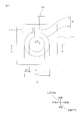
- FIG. 1 shows a bottom view of a first module obtained by the first embodiment of the module manufacturing method of the present invention.
- 2A to 2I are manufacturing process diagrams of a first module manufacturing method which is a first embodiment of the module manufacturing method of the present invention.
- FIG. 2A shows a conductor layer arranged in the first release layer.
- 2B is a step of arranging an etching resist
- FIG. 2C is a step of etching the conductor layer
- FIG. 2D is a second step of removing the etching resist to form a coil pattern
- FIG. 2E. 2F is a step of bringing the first adhesive layer into contact with the coil pattern
- FIG. 2F is a fifth step of transferring the coil pattern from the first release layer to the first adhesive layer
- FIG. 2G is a lower surface of the coil pattern. 6H, FIG. 2H is a third step (fourth step, seventh step, eighth step) for pushing the coil pattern into the first adhesive layer (cross-sectional view along the line AA in FIG. 1), FIG. 2I shows the first adhesive layer and the coil pattern. Showing a process of manufacturing a first module comprising down.
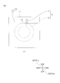
- FIG. 3 is a bottom view of the second module obtained by the second embodiment of the module manufacturing method of the present invention.
- 4A to 4D are manufacturing process diagrams of the second module manufacturing method according to the second embodiment of the module manufacturing method of the present invention.
- FIG. 4A shows the second adhesion arranged on the third release layer.
- FIG. 4B is a step of preparing a layer, FIG.
- FIG. 4B is a tenth step of covering the coil pattern with the second adhesive layer, and embedding the coil pattern with the adhesive layer
- FIG. 4C is a step of preparing two magnetic layers
- positioning a magnetic layer to a contact bonding layer is shown.
- 5A to 5F are manufacturing process diagrams of a third module manufacturing method which is a third embodiment of the module manufacturing method of the present invention.
- FIG. 5A is a two-layer base material including a conductor layer and a support layer.
- 5B is a first step of bonding the first release layer to the two-layer base material
- FIG. 5C is a step of placing an etching resist
- FIG. 5D is a step of etching the conductor layer to form a coil pattern.
- FIG. 5E shows the third step of pushing the coil pattern into the first adhesive layer, and the fourth step of peeling off the first release layer.
- FIG. 5F shows the ninth step of further providing the magnetic layer.
- . 6A to 6D are manufacturing process diagrams of a fourth module manufacturing method according to the fourth embodiment of the module manufacturing method of the present invention.
- FIG. 6A shows the second adhesion arranged on the third release layer.
- Step of preparing the layer FIG. 6B is a step of covering the support layer with the second adhesive layer, and sandwiching the coil pattern and the support layer with the adhesive layer
- FIG. 6C is a step of preparing two magnetic layers
- FIG. 6D shows the 12th process of arrange
- the vertical direction of the paper surface is the vertical direction (an example of the thickness direction, the first direction)
- the upper side of the paper surface is the upper side (one side in the thickness direction, the first direction side)
- the lower side of the paper surface is the lower side ( The other side in the thickness direction and the other side in the first direction).
- the horizontal direction of the paper is the horizontal direction (second direction orthogonal to the first direction, the width direction), and the right side of the paper is the right side (one side in the width direction, one side in the second direction)
- the left side of the drawing is the left side (the other side in the width direction and the other side in the second direction).
- the vertical direction of the paper surface is the front-back direction (a third direction orthogonal to the first direction and the second direction), the lower side of the paper surface is the front side (one side in the third direction), and the upper side of the paper surface is the rear side (the first side). 3 direction other side).
- First Module Manufacturing Method A first module 1 manufacturing method according to a first embodiment of the module manufacturing method of the present invention will be described with reference to FIGS. 1 and 2A to 2I.
- the manufacturing method of the first module 1 includes a first step of preparing a conductor layer 3 disposed on the first release layer 2 (see FIG. 2A), and a coil pattern 5 as an example of a conductor pattern from the conductor layer 3.
- a second step see FIG. 2D
- a third step for pushing the coil pattern 5 into the first adhesive layer 11 containing the first magnetic particles and the first resin component, 1
- the 4th process (refer the arrow of FIG. 2H) which peels the peeling layer 2 is provided.
- the first to fourth steps are sequentially performed in this order. Hereinafter, each process is demonstrated in order.
- a conductor layer 3 disposed on the upper surface (an example of one surface in the thickness direction) of the first release layer 2 is prepared.
- the first release layer 2 has a substantially flat plate (sheet) shape extending in a plane direction (front-rear direction and left-right direction in FIG. 1) perpendicular to the thickness direction.
- the first release layer 2 is a support layer that supports the conductor layer 3 until the conductor layer 3 is contoured to form the coil pattern 5.
- the first release layer 2 is also a transfer substrate (release layer) for transferring the coil pattern 5 to the first adhesive layer 11 (see FIG. 2D).
- the first release layer 2 preferably has pressure-sensitive adhesiveness (tackiness).
- the first release layer 2 includes a pressure-sensitive adhesive layer (pressure-sensitive adhesive layer) 22 and a support plate 21 that supports the pressure-sensitive adhesive layer 22.
- the pressure sensitive adhesive layer 22 is formed in a sheet shape from a pressure sensitive adhesive such as an acrylic pressure sensitive adhesive.
- the thickness of the pressure-sensitive adhesive layer 22 is, for example, 0.1 ⁇ m or more, preferably 1 ⁇ m or more, and for example, 100 ⁇ m or less, preferably 10 ⁇ m or less.
- the support plate 21 is formed in a flexible sheet shape from, for example, a polymer material such as polyethylene terephthalate (PET).
- PET polyethylene terephthalate
- the support plate 21 is disposed on the lower surface of the pressure sensitive adhesive layer 22 and supports the pressure sensitive adhesive layer 22. Further, the support plate 21 may be a metal foil, a ceramic sheet, or the like.
- the thickness of the support plate 21 is, for example, 1 ⁇ m or more, preferably 10 ⁇ m or more, and for example, 1000 ⁇ m or less, preferably 100 ⁇ m or less.
- the ratio of the thickness of the support plate 21 to the thickness of the pressure-sensitive adhesive layer 22 is, for example, 0.01 or more, preferably 0.05 or more, and for example, 10 or less, preferably 1 or less. .
- the conductor layer 3 has a substantially flat plate (sheet) shape extending in the surface direction.
- the conductor layer 3 is not a coil pattern 5 (see FIG. 2D) but a coil preparation body for forming the coil pattern 5. That is, the conductor layer 3 does not yet have the coil portion 6 and the terminal portion 7 (described later, see FIG. 1) included in the coil pattern 5.
- the conductor layer 3 is in contact with the upper surface of the first release layer 2. Specifically, the conductor layer 3 is pressure-sensitive bonded (attached) to the entire upper surface of the pressure-sensitive adhesive layer 22 in the first release layer 2.
- Examples of the material for forming the conductor layer 3 include conductors such as copper, nickel, gold, silver, aluminum, tungsten, solder, or alloys thereof. Preferably, copper is used.
- the thickness of the conductor layer 3 is, for example, 1 ⁇ m or more, preferably 5 ⁇ m or more, and preferably 30 ⁇ m or more from the viewpoint of reducing the resistance of the conductor layer 3. Further, the thickness of the conductor layer 3 is, for example, 200 ⁇ m or less, preferably 100 ⁇ m or less, and preferably 70 ⁇ m or less from the viewpoint of reducing the thickness of the first module 1.
- the conductor layer 3 is disposed on the upper surface of the first release layer 2. Specifically, the conductor layer 3 is pressure-bonded (attached) to the upper surface of the pressure-sensitive adhesive layer 22 in the first release layer 2.
- a laminate including the conductor layer 3 and the first release layer 2 can be prepared in advance.
- the coil pattern 5 is formed from the conductor layer 3 in the second step.
- the conductor layer 3 is trimmed to form the coil pattern 5.
- the coil pattern 5 is formed by a subtractive method.
- the etching resist 8 is disposed on the upper surface of the conductor layer 3.
- a photoresist such as a dry film resist having a sheet shape is disposed on the entire upper surface of the conductor layer 3, and then an etching resist 8 having the same pattern as the coil pattern 5 (see FIG. 1) is formed by photolithography. To do.
- the conductor layer 3 exposed from the etching resist 8 is removed by etching.
- the etching include wet etching and dry etching. From the viewpoint of productivity and cost reduction, wet etching is preferable.
- the first peeling layer 2, the conductor layer 3, and the etching resist 8 are immersed in an etching solution.
- the etching solution is not particularly limited as long as it can etch the conductor, and examples thereof include a ferric chloride solution and a mixed solution of sulfuric acid and hydrogen peroxide.
- the etching time is, for example, 20 seconds or longer, preferably 30 seconds or longer, and for example, 5 minutes or shorter, preferably 3 minutes or shorter.
- the etching resist 8 is removed.
- the etching resist 8 is stripped with a stripping solution.
- the coil pattern 5 has a coil portion 6 and a terminal portion 7 continuously.
- the coil portion 6 has a substantially annular shape in plan view with a rear end portion notched or a substantially rectangular frame shape in plan view.
- the coil portion 6 has a substantially C shape in plan view with the rear side open.
- the terminal portion 7 has a substantially linear shape in plan view extending rearward from each of the two rear end portions of the coil pattern 5.
- the dimensions of the coil pattern 5 are not particularly limited.
- the width W1 of the coil part 6 is, for example, 20 ⁇ m or more, preferably 50 ⁇ m or more, and for example, 100 mm or less, preferably 1000 ⁇ m or less.
- the inner dimension (inner diameter) L1 of the coil portion 6 is, for example, 20 ⁇ m or more, preferably 50 ⁇ m or more, and for example, 500 mm or less, preferably 5 mm or less.
- the outer dimension (outer diameter) L2 of the coil portion 6 is, for example, 60 ⁇ m or more, preferably 150 ⁇ m or more, and, for example, 500 mm or less, preferably 5 mm or less.
- the distance L3 between the two rear end portions in the left-right direction of the coil unit 6 is, for example, 20 ⁇ m or more, preferably 50 ⁇ m or more, and, for example, 300 mm or less, preferably 2 mm or less.
- the cross-sectional area S of the coil pattern 5 is, for example, 20 ⁇ m 2 or more, preferably 2500 ⁇ m 2 or more, and for example, 20 mm 2 or less, preferably 0.1 mm 2 or less.
- the length (width) W2 of the terminal portion 7 in the left-right direction is, for example, 20 ⁇ m or more, preferably 50 ⁇ m or more, and for example, 20 mm or less, preferably 10 mm or less.
- the front-rear direction length L4 of the terminal portion 7 is, for example, 20 ⁇ m or more, preferably 50 ⁇ m or more, and for example, 20 mm or less, preferably 10 mm or less.
- the interval between the adjacent terminal portions 7 is the same as the distance L3 between the rear end portions of the coil portion 6 described above.
- the third step is a fifth step (see FIG. 2F) in which the coil pattern 5 is transferred from the upper surface of the first release layer 2 to the lower surface of the first adhesive layer 11 (an example of one surface in the thickness direction), and the second release layer 9. Is disposed on the lower surface of the coil pattern 5 (an example of one surface in the thickness direction) (see FIG. 2G), the second release layer 9 is pressure-bonded to the first adhesive layer 11, and the coil pattern 5 is It includes a seventh step (see FIG. 2H) for pushing into the first adhesive layer 11 and an eighth step (see the arrow in FIG. 2H) for peeling the second release layer 9. In the third step, the fifth to eighth steps are sequentially performed in this order. Hereinafter, each of the fifth to eighth steps will be described in order.
- the first adhesive layer 11 is prepared.
- the first adhesive layer 11 has a substantially flat plate shape extending in the surface direction.
- the first adhesive layer 11 contains first magnetic particles and a first resin component. Specifically, the first adhesive layer 11 is prepared from a first adhesive resin composition containing first magnetic particles and a first resin component.
- Examples of the first magnetic particles include soft magnetic particles and ferromagnetic particles, and preferably include soft magnetic particles.
- the soft magnetic particles include particles composed of at least one selected from iron and iron alloys. Examples of such soft magnetic particles include magnetic stainless steel (Fe—Cr—Al—Si alloy) particles, sendust (Fe—Si—A1 alloy) particles, permalloy (Fe—Ni alloy) particles, silicon copper (Fe—).
- Cu-Si alloy) particles Fe-Si alloy particles, Fe-Si-B (-Cu-Nb) alloy particles, Fe-Si-Cr alloy particles, Fe-Si-Cr-Ni alloy particles, Fe-Si-Cr Examples thereof include alloy particles, Fe—Si—Al—Ni—Cr alloy particles, carbonyl iron particles, ferrite particles (specifically, Ni—Zn ferrite particles). Among these, from the viewpoint of magnetic properties, Fe—Si—Cr alloy particles and Ni—Zn ferrite particles are preferable.
- the soft magnetic particles include those described in publicly known documents such as Japanese Patent Application Laid-Open Nos. 2016-108561, 2016-006853, 2016-6852, and 2016-006163. Examples include magnetic particles.
- the volume ratio of the first magnetic particles in the first adhesive layer 11 is, for example, 15% by volume or more, preferably 20% by volume or more, more preferably 30% by volume or more, and further preferably 40% by volume or more. . If the capacity ratio of the first magnetic particles is equal to or higher than the lower limit, the inductance of the first module 1 can be improved. Further, the volume ratio of the first magnetic particles in the first adhesive layer 11 is, for example, 70% by volume or less, 65% by volume or less, and preferably 60% by volume or less. If the volume ratio of the first magnetic particles is equal to or less than the above upper limit, the coil pattern 5 can be reliably pushed into the first adhesive layer 11 and the film forming property of the first adhesive resin composition is excellent. .
- the mass ratio of the first magnetic particles in the first adhesive layer 11 is, for example, 44% by mass or more, preferably 53% by mass or more, more preferably 66% by mass or more, and further preferably 75% by mass or more. It is. If the mass ratio of the first magnetic particles is greater than or equal to the above lower limit, the inductance of the first module 1 can be improved.
- the mass ratio of the first magnetic particles in the first adhesive layer 11 is, for example, 93% by mass or less, and preferably 91% by mass or less. If the mass ratio of the first magnetic particles is equal to or less than the above upper limit, the pressure-sensitive adhesiveness of the first adhesive layer 11 can be improved and the film forming property of the first adhesive resin composition is excellent.
- the first resin component examples include the resin components described in the above-mentioned publicly known literature.
- the resin component can be used alone or in combination.
- an epoxy resin, a phenol resin and an acrylic resin are used in combination. If an epoxy resin, a phenol resin, and an acrylic resin are used in combination as the first resin component, the coil pattern 5 can be surely pushed into the first adhesive layer 11, and excellent flexibility and excellent heat resistance can be obtained. It can be applied to the adhesive layer 11.
- the first adhesive resin composition is prepared by blending the first particles and the first resin component.
- the first adhesive resin composition can also be blended with the additives (thermosetting catalyst, dispersant, rheology control agent, etc.) described in the above-mentioned known literature.
- the 1st adhesive resin composition can also be prepared as a 1st adhesive resin composition solution containing a solvent further.
- the first adhesive resin composition solution is applied to the surface of the release layer 10 (the lower surface in FIG. 2D). Thereafter, the first adhesive resin composition solution is dried by heating to remove the solvent.
- the first adhesive layer 11 is disposed on the lower surface of the release layer 10.
- the first adhesive layer 11 of the B stage is disposed on the lower surface of the release layer 10.
- the first adhesive resin composition of the A stage becomes the B stage by drying the first adhesive resin composition solution.
- the release layer 10 is, for example, a separator having a substantially flat plate shape extending in the surface direction from the polymer material exemplified by the support plate 21. Moreover, the surface (lower surface) of the peeling layer 10 is subjected to an appropriate peeling treatment, for example.
- the thickness of the release layer 10 is, for example, 15 ⁇ m or more, preferably 30 ⁇ m or more, and for example, 100 ⁇ m or less, preferably 75 ⁇ m or less.
- the pressure-sensitive adhesive force PS2 of the first adhesive layer 11 to the coil pattern 5 is higher than the pressure-sensitive adhesive force PS1 of the first release layer 2 (pressure-sensitive adhesive layer 22) to the coil pattern 5 (conductor layer 3). That is, the relationship PS1 ⁇ PS2 is satisfied.
- the first release layer 2 does not contact the first adhesive layer 11 (described later), but the pressure-sensitive adhesive force PS3 of the first release layer 2 to the first adhesive layer 11 (modified example of the first embodiment described later).
- 2H (see reference numeral 2 in parentheses in FIG. 2H) is relatively high.
- PS3 is higher than PS2. That is, the relationship PS2 ⁇ PS3 is satisfied.
- the first adhesive layer 11 disposed on the lower surface of the release layer 10 is formed.
- the release layer 10 and the first adhesive layer 11 are disposed to face the upper side of the coil pattern 5 so that the first adhesive layer 11 faces the coil pattern 5, and then, as shown in FIG. 2E, the first adhesive layer The lower surface of 11 is brought into contact with the upper surface of the coil pattern 5.
- the lower surface of the first adhesive layer 11 and the upper surface of the first release layer 2 are separated from each other by the thickness of the coil pattern 5. Is placed on the coil pattern 5. That is, the first release layer 2 does not contact the first adhesive layer 11.
- the first release layer 2 is peeled from the coil pattern 5.
- a fifth step of transferring the coil pattern 5 from the first release layer 2 to the first adhesive layer 11 is performed.
- the second release layer 9 is disposed on the lower surface of the coil pattern 5.
- the first release layer 2 is pressed into the first adhesive layer 11.
- the second release layer 9 is a separator having a substantially flat plate shape extending in the surface direction.
- the second release layer 9 is formed from, for example, the polymer material exemplified for the support plate 21. Moreover, the surface (upper surface) of the 2nd peeling layer 9 is given the appropriate peeling process, for example.
- the second release layer 9 is not in contact with the first adhesive layer 11, but the pressure-sensitive adhesive force PS4 (see FIG. 2H) of the second release layer 9 to the first adhesive layer 11 is Relatively low (specifically very low). Further, the pressure-sensitive adhesive force PS4 of the second release layer 9 to the first adhesive layer 11 is lower than the pressure-sensitive adhesive force PS3 of the first release layer 2 to the first adhesive layer 11. Furthermore, PS4 is low also with respect to the pressure-sensitive adhesive force PS1 with respect to the coil pattern 5 of the 1st peeling layer 2. FIG. That is, PS4 ⁇ PS1 is satisfied.
- each pressure-sensitive adhesive force satisfies the following formula.
- the thickness of the 2nd peeling layer 9 is 15 micrometers or more, for example, Preferably, it is 30 micrometers or more, for example, is 100 micrometers or less, Preferably, it is 75 micrometers or less.
- the sixth step and the seventh step are continuously performed by using a press machine such as a vacuum press machine.
- the release layer 10, the first adhesive layer 11, the coil pattern 5, and the second release layer 9 are installed in a press machine (not shown) including an upper plate and a lower plate.
- a press machine including an upper plate and a lower plate.
- the release layer 10, the first adhesive layer 11, and the coil pattern 5 are installed on the upper plate, and the second release layer 9 is installed on the lower plate.
- the press machine is driven to press the second release layer 9 against the first adhesive layer 11 and press the coil pattern 5 into the first adhesive layer 11 as shown by the arrow in FIG. 2F and FIG. 2H. .
- the seventh step is performed.
- the coil pattern 5 digs into the first adhesive layer 11, and a portion of the first adhesive layer 11 that faces the coil pattern 5 in the thickness direction wraps around the side of the coil pattern 5.
- the side surface of the coil pattern 5 is covered with the first adhesive layer 11.
- the upper surface of the second release layer 9 and the lower surface of the first adhesive layer 11 are in contact with each other at portions other than the coil pattern 5.
- the lower surface of the coil pattern 5 and the lower surface of the first adhesive layer 11 are flush with each other and are continuous in the surface direction.
- the release layer 10 is peeled from the first adhesive layer 11 as indicated by the upper arrow in FIG. 2H.
- the upper surface of the first adhesive layer 11 is exposed upward.
- the first module 1 including the first adhesive layer 11 and the coil pattern 5 is manufactured.
- the first module 1 preferably includes only the first adhesive layer 11 and the coil pattern 5.
- the first module 1 of the first embodiment is an intermediate member of the second module 31 (described later) in the second embodiment, and does not include the second adhesive layer 12 (described later, see FIG. 4B).
- the first module 1 is a member that can be used industrially.
- the first module 1 is heated to make the first adhesive layer 11 a C stage.
- the thickness of the first module 1 is, for example, 750 ⁇ m or less, preferably 500 ⁇ m or less, more preferably 300 ⁇ m or less, and for example, 50 ⁇ m or more.
- the thickness of the first module 1 is the distance between the lower surface of the coil pattern 5 and the upper surface of the first adhesive layer 11. If the thickness of the first module 1 is equal to or less than the upper limit described above, the first module 1 can be thinned.
- the inductance of the first module 1 is, for example, 0.1 nH or more, preferably 0.5 nH or more, more preferably 1 nH or more.
- the inductance is measured by an impedance analyzer (E4991B, 1 GHz, manufactured by KEYSIGHT). Subsequent inductance is measured by the same method as described above.
- the first module 1 obtained by the manufacturing method of the first module 1 includes an inductor.
- the first module 1 is used for, for example, wireless power transmission (wireless power feeding), wireless communication, a sensor, and the like. Since the lower surface of the coil pattern 5 is exposed, the first module 1 is preferably used for wireless power transmission and wireless communication.
- the first module 1 that does not include the ferrite substrate as in Patent Document 1 can be manufactured. Therefore, the thickness of the first module 1 can be reduced.
- the coil pattern 5 is pushed into the first adhesive layer 11 containing the first magnetic particles. It is possible to ensure high inductance while further reducing the thickness of 1.
- the coil pattern 5 is formed from the conductor layer 3 in a short time as compared with the method described in Patent Document 1 using plating. can do.
- the first peeling layer 2 is peeled off from the coil pattern 5, so that the coil pattern 5 can be reliably exposed.
- the coil pattern 5 is transferred from the upper surface of the first release layer 2 to the lower surface of the first adhesive layer 11, As shown in 2G, in the sixth step, the second release layer 9 having a pressure-sensitive adhesive force PS4 for the first adhesive layer 11 lower than the pressure-sensitive adhesive force P3 for the first adhesive layer 11 of the first release layer 2, It is arranged on the lower surface of the coil pattern 5. Then, as shown in FIG. 2H, even if the second release layer 9 is pressure-bonded to the first adhesive layer 11 in the seventh step, the second release layer 9 is pressure-sensitively bonded to the first adhesive layer 11. The coil pattern 5 can be pushed into the first adhesive layer 11 while suppressing this.
- the second release layer 9 can be easily and reliably peeled from the first adhesive layer 11 in the eighth step.
- the conductor layer 3 is etched to form the coil pattern 5
- the plating described in Patent Document 1 is performed.
- the coil pattern 5 can be formed in a short time.
- the inductance can be improved if the content ratio of the first magnetic particles in the first adhesive layer 11 is 15% by volume or more. Moreover, if the content rate of the 1st magnetic particle in the 1st contact bonding layer 11 is 60 volume% or less, the coil pattern 5 can be pushed in with respect to the 1st contact bonding layer 11 reliably. Therefore, it is possible to achieve both improvement in inductance and improvement in pushability of the coil pattern 5 with respect to the first adhesive layer 11.
- the first resin component is an epoxy resin, a phenol resin, and an acrylic resin in the manufacturing method of the first module 1, in the third step, as shown in FIG.
- the first module 1 that can be reliably pushed into the adhesive layer 11 and has excellent flexibility and excellent heat resistance can be manufactured.
- the conductor layer 3 is etched in the second step.
- the outer shape processing of the conductor layer 3 is not limited to this.
- a cutting line 28 is formed on the conductor layer 3 with a cutting blade 27 (virtual line).
- the part other than the coil pattern 5 can also be removed.
- the conductor layer 3 is etched. If the conductor layer 3 is etched, the coil pattern 5 can be formed in a shorter time than the plating of the additive method of Patent Document 1. Furthermore, if the conductor layer 3 is etched, the coil pattern 5 can be formed with high accuracy.
- the coil pattern 5 is transferred from the first release layer 2 to the first adhesive layer 11 in the fifth step, and as shown in FIG. 2F.
- the second release layer 9 is disposed on the lower surface of the coil pattern 5, and subsequently, in the seventh step, the second release layer 9 is attached to the first adhesive layer 11 as shown in FIG. 2H. Crimped. That is, after the first release layer 2 is once peeled from the lower surface of the coil pattern 5, the second release layer 9 is disposed on the lower surface of the coil pattern 5, and the second release layer 9 is pressed against the first adhesive layer 11. To do.
- the first peeling layer 2 is not peeled, the second peeling layer 9 is not disposed, and the first peeling layer 2 is used as it is.
- the layer 2 can also be pressure-bonded to the first adhesive layer 11.
- the second release layer 9 is disposed as shown in FIG. 2G, and the second release layer as shown in FIG. 2H. 9 is pressed against the first adhesive layer 11.
- the coil pattern 5 is transferred from the upper surface of the first release layer 2 to the lower surface of the first adhesive layer 11, and as shown in FIG. In 6 processes, the 2nd peeling layer 9 which has pressure sensitive adhesive force PS4 with respect to the 1st adhesive layer 11 lower than the pressure sensitive adhesive force PS3 with respect to the 1st adhesive layer 11 of the 1st peeling layer 2 is arrange
- the second release layer 9 can be easily and reliably peeled from the first adhesive layer 11 in the eighth step.
- the number of coil patterns 5 is 1, but the number is not particularly limited, and may be, for example, a plurality.
- the manufacturing method of the first module 1 includes the ninth step of disposing the magnetic layer 18 on the upper surface of the first adhesive layer 11 (an example of the other surface in the thickness direction). Furthermore, it can be provided.
- the magnetic layer 18 is prepared.
- the magnetic layer 18 is a core material for converging the magnetic field generated in the coil pattern 5 and amplifying the magnetic flux, and prevents magnetic flux leakage to the outside of the coil pattern 5 (or noise from the outside of the coil pattern 5). This is a shielding material for shielding the coil pattern 5.
- the magnetic layer 18 has a substantially flat plate (sheet) shape extending in the plane direction.
- the magnetic layer 18 contains second magnetic particles and a second resin component. Specifically, the magnetic layer 18 is formed from a magnetic resin composition containing second magnetic particles and a second resin component.
- Examples of the second magnetic particles include the same magnetic particles as the first magnetic particles, and preferably, Sendust (Fe—Si—A1 alloy) particles are used from the viewpoint of magnetic properties.
- Sendust (Fe—Si—A1 alloy) particles are used from the viewpoint of magnetic properties.
- the physical properties such as the shape, holding power, average particle diameter, and average thickness of the second magnetic particles, the physical properties described in the above-mentioned known literatures are employed.
- the volume ratio of the second magnetic particles in the magnetic layer 18 is, for example, 40% by volume or more, preferably 45% by volume or more, more preferably 48% by volume or more, and still more preferably 60% by volume or more. 90 volume% or less, preferably 85 volume% or less, and more preferably 80 volume% or less. If the capacity ratio of the second magnetic particles is equal to or higher than the above lower limit, the inductance of the first module 1 can be further improved. When the volume ratio of the second magnetic particles is equal to or less than the above upper limit, the film forming property of the magnetic resin composition is excellent.
- the mass ratio of the second magnetic particles in the magnetic layer 18 is, for example, 80% by mass or more, preferably 83% by mass or more, more preferably 85% by mass or more, and, for example, 98% by mass or less. Preferably, it is 95 mass% or less, More preferably, it is 90 mass% or less.
- the mass ratio of the second magnetic particles is equal to or greater than the lower limit described above, the magnetic characteristics of the first module 1 are excellent. If the mass ratio of the second magnetic particles is not more than the above upper limit, the magnetic resin composition is excellent.
- the same resin component as the first resin component can be mentioned, and preferably, an epoxy resin, a phenol resin and an acrylic resin are used in combination. If an epoxy resin, a phenol resin, and an acrylic resin are used in combination as the second resin component, excellent flexibility and excellent heat resistance can be imparted to the magnetic layer 18.
- a magnetic resin composition is prepared by blending the second magnetic particles and the second resin component.
- the additive a thermosetting catalyst, a dispersing agent, a rheology control agent etc.
- the magnetic resin composition can also be prepared as a magnetic resin composition solution further containing a solvent. And a magnetic resin composition solution is apply
- a B-stage magnetic layer 18 is prepared.
- the magnetic layer 18 is a B-stage, a plurality of magnetic layers 18 are stacked in the thickness direction, and they are hot-pressed in the thickness direction to form the C-stage magnetic layer 18.
- the number of laminated magnetic layers 18 is not particularly limited, and is, for example, 2 or more, preferably 5 or more, and for example, 20 or less, preferably 10 or less.
- the conditions described in the above-mentioned publicly known documents are appropriately adopted as the hot press conditions.
- the average thickness of the magnetic layer 18 is, for example, 5 ⁇ m or more, preferably 10 ⁇ m or more, and, for example, 500 ⁇ m or less, preferably 250 ⁇ m or less.
- the magnetic layer 18 is brought into contact with the upper surface of the first adhesive layer 11.
- the magnetic layer 18 is pressure-bonded to the first adhesive layer 11.
- the magnetic layer 18 is attached to the first adhesive layer 11 using a press such as a vacuum press.
- the magnetic layer 18 is pressure-sensitively bonded to the upper surface of the first adhesive layer 11. Thereafter, if necessary, the first adhesive layer 11 is made to be a C stage, and the magnetic layer 18 is bonded to the first adhesive layer 11.
- the first module 1 of this modification includes a first adhesive layer 11, a coil pattern 5, and a magnetic layer 18.
- the first module 1 includes only the first adhesive layer 11, the coil pattern 5, and the magnetic layer 18.
- This modification can also provide the same operational effects as the first embodiment.
- the magnetic layer 18 is disposed on the upper surface of the first adhesive layer 11 in the ninth step as shown by the phantom line in FIG.
- the inductance can be further improved.
- the release layer 10, the first adhesive layer 11, and the coil pattern 5 are installed on the upper plate, and the second release layer 9 is installed on the lower plate.
- the release layer 10, the first adhesive layer 11, the coil pattern 5, and the second release layer 9 can be installed only on the upper plate.
- all of the release layer 10, the first adhesive layer 11, the coil pattern 5, and the second release layer 9 can be installed only on the lower plate.
- the first module 1 in which the lower surface of the coil pattern 5 is exposed is manufactured.
- the manufacturing method of the second module 31 of the second embodiment covers the first adhesive layer 11 and the second adhesive by covering the lower surface of the coil pattern 5 with the second adhesive layer 12.
- the adhesive layer 13 including the layer 12 further includes a tenth step of embedding the coil pattern 5.
- the method of manufacturing the second module 31 of the second embodiment further includes a twelfth step of disposing each of the two magnetic layers 18 on the upper surface and the lower surface of the adhesive layer 13, respectively. Prepare.
- the second module 31 of the second embodiment is preferably used for a sensor because the coil pattern 5 is embedded in the adhesive layer 13.
- the adhesive layer 13 for embedding the coil pattern 5 is formed, so that the inductance of the second module 31 is further improved. Can be made.
- the magnetic layer 18 is disposed on the upper and lower surfaces of the adhesive layer 13, so that the inductance of the second module 31 is increased. This can be further improved.
- the magnetic layer 18 can further improve the inductance. .
- the second module 31 is composed of the coil pattern 5 and the adhesive layer 13 in which the coil pattern 5 is embedded without including the magnetic layer 18. You can also. In that case, the manufacturing method of the second module 31 does not include the twelfth step shown in FIG. 4D.
- the number of coil patterns 5 is 1, but the number is not particularly limited, and may be, for example, a plurality. If the number of the coil patterns 5 is plural, the second module 31 can be suitably used as a sensor.
- the third module 33 includes a support layer 14 in addition to the coil pattern 5 and the first adhesive layer 11.
- the support layer 14 is a base sheet (thin film) that supports the coil pattern 5 from below.
- the support layer 14 has a substantially rectangular sheet shape in plan view.
- the support layer 14 forms the lower surface of the third module 33.
- the support layer 14 is in contact with the lower surface of the coil pattern 5 and the lower surface of the first adhesive layer 11.
- the material of the support layer 14 is a material having toughness, and examples thereof include resins such as polyimide, polyester, polyolefin, and fluororesin, and preferably polyimide.
- the thickness of the support layer 14 is, for example, 20 ⁇ m or less, preferably 10 ⁇ m or less, and for example, 0.1 ⁇ m or more, preferably 0.5 ⁇ m or more.
- the conductor layer 3 disposed on the support layer 14 is prepared. Specifically, the conductor layer 3 disposed on the upper surface (an example of one surface in the thickness direction) of the support layer 14 is prepared. For example, the two-layer base material 19 provided with the support layer 14 and the conductor layer 3 in order is prepared.
- the first release layer 2 is bonded to the lower surface of the support layer 14. That is, the conductor layer 3 is laminated on the first release layer 2 via the support layer 14. Thereby, in a 1st process, the 3 layer base material 32 provided with the 1st peeling layer 2, the support layer 14, and the conductor layer 3 in order is prepared.
- an etching resist 8 is then disposed on the upper surface of the conductor layer 3.
- the conductor layer 3 exposed from the etching resist 8 is removed by etching. Thereby, the coil pattern 5 is formed.
- the coil pattern 5 is then pushed into the first adhesive layer 11.
- the second release layer 9 is peeled from the coil pattern 5 and the first adhesive layer 11 as indicated by a virtual line.
- the third module 33 including the support layer 14, the coil pattern 5, and the first adhesive layer 11 is manufactured.
- the third module 33 is heated or heated while being pressed, so that the first adhesive layer 11 is changed to a C stage.
- the third module 33 of the third embodiment is an intermediate member of the fourth module 34 (described later) in the fourth embodiment, and does not include the second adhesive layer 12 (described later, see FIG. 6B).
- the third module 33 is an industrially usable member.
- the conductor layer 3 is laminated on the first release layer 2 via the support layer 14 in the first step.
- the coil pattern 5 can be pushed into the first adhesive layer 11 while being supported by the support layer 14.
- the manufacturing method of the third module 33 since the coil pattern 5 is supported by the support layer 14, the displacement of the coil pattern 5 during the above-described C-staging process can be suppressed. The positional accuracy can be improved. Therefore, it is possible to manufacture the third module 33 having the designed inductance while preventing the above-described inductance deviation.
- the third module 33 in which the lower surface of the support layer 14 is exposed is manufactured.
- the fourth module 34 of the fourth embodiment is manufactured by covering the lower surface of the support layer 14 with the second adhesive layer 12, so that the first adhesive layer 11 and the second adhesive layer are bonded.
- An eleventh step of sandwiching the coil pattern 5 and the support layer 14 in the thickness direction by the adhesive layer 13 including the layer 12 is further provided.
- the method of manufacturing the fourth module 34 of the fourth embodiment further includes a twelfth step of disposing each of the two magnetic layers 18 on the upper surface and the lower surface of the adhesive layer 13, respectively. Prepare.
- the lower surface of the support layer 14 is covered with the second adhesive layer 12.
- An adhesive layer 13 including the first adhesive layer 11 and the second adhesive layer 12 is obtained.
- the coil pattern 5 and the support layer 14 are sandwiched in the vertical direction by the adhesive layer 13.
- the third release layer 15 is peeled from the second adhesive layer 12 (the lower surface of the adhesive layer 13).
- the release layer 10 is released from the first adhesive layer 11 (the upper surface of the adhesive layer 13).
- the two magnetic layers 18 are respectively disposed on the upper surface and the lower surface of the adhesive layer 13.
- each of the two magnetic layers 18 is pressure-sensitively bonded to the upper surface and the lower surface of the adhesive layer 13 as indicated by arrows in FIG. 6C.
- the fourth module 34 is heated or heated while being pressed to make the adhesive layer 13 a C stage.
- a fourth module 34 is manufactured.
- the adhesive layer 13 sandwiching the coil pattern 5 and the support layer 14 is formed in the eleventh step, so that the positional accuracy of the coil pattern 5 is improved.
- the inductance of the fourth module 34 can be further improved.
- Example 1 (Example corresponding to the second embodiment) (First step) As shown in FIG. 2A, a conductor layer 3 made of copper and having a thickness of 50 ⁇ m is pressure-sensitive on the upper surface of the first release layer 2 having a thickness of 55 ⁇ m. Glued.
- the first release layer 2 includes a support plate 21 made of PET and having a thickness of 50 ⁇ m and a pressure-sensitive adhesive layer 22 made of an acrylic pressure-sensitive adhesive and having a thickness of 5 ⁇ m.
- the first step of preparing the conductor layer 3 on the upper surface of the first release layer 2 was performed.
- the coil pattern 5 was formed by a subtractive method. That is, first, as shown in FIG. 2B, a photoresist is arranged on the entire upper surface of the conductor layer 3, and then the photoresist is photoprocessed to form a coil on the upper surface of the conductor layer 3 as shown in FIG. 1A. An etching resist 8 having the same pattern as the pattern 5 is disposed. Subsequently, as shown in FIG. 2C, the conductor layer 3 exposed from the etching resist 8 was removed by etching. Note that a ferric chloride solution was used as an etchant, and the first release layer 2, the conductor layer 3, and the etching resist 8 were immersed for 90 seconds. Thereafter, as shown in FIG. 2D, the etching resist 8 was stripped with a stripping solution.
- the coil pattern 5 has an inner dimension L1: 1900 ⁇ m, an outer dimension L2: 3100 ⁇ m, a width W1: 600 ⁇ m, a distance L3 between two rear end portions L3: 600 ⁇ m, and a width W2. : Two terminal portions 7 of 200 ⁇ m are continuously provided.
- a first adhesive layer 11 was prepared.
- first adhesive layer 11 To prepare the first adhesive layer 11, first, according to Table 1, each component is blended to prepare an adhesive resin composition (first adhesive resin composition), and then the adhesive resin composition is dissolved in methyl ethyl ketone. Thus, an adhesive resin composition solution having a solid content concentration of 35% by mass was prepared. Next, the adhesive resin composition solution was applied to the surface of a 50 ⁇ m thick release layer 10 (model number “MRA50”, manufactured by Mitsubishi Plastics) made of PET, and then dried at 110 ° C. for 2 minutes. Thereby, as shown to FIG. 2D, the 1st contact bonding layer 11 of B stage with an average thickness of 45 micrometers was prepared.
- first adhesive resin composition an adhesive resin composition having a solid content concentration of 35% by mass
- the coil pattern 5 was then transferred from the first release layer 2 to the first adhesive layer 11 (fifth step).
- the release layer 10 and the first adhesive layer 11 are arranged to face the upper side of the coil pattern 5 so that the first adhesive layer 11 faces downward, and then, as shown in FIG.
- the lower surface of one adhesive layer 11 was brought into contact with the upper surface of the coil pattern 5.
- the lower surface of the first adhesive layer 11 and the upper surface of the first release layer 2 are separated from each other by the thickness of the coil pattern 5.
- the first release layer 2 was peeled from the coil pattern 5 as shown by the arrow in FIG. 2E and FIG. 2F.
- the second release layer 9 was then disposed on the lower surface of the coil pattern 5 (sixth step).
- a 50 ⁇ m-thick second release layer 9 made of PET (model number “MRA50”, manufactured by Mitsubishi Plastics) was prepared. Then, the coil pattern 5 and the 2nd peeling layer 9 were installed in the vacuum press machine (not shown) which has an upper board and a lower board. Specifically, the release layer 10, the first adhesive layer 11, and the coil pattern 5 were installed on the upper plate, and the second release layer 9 was installed on the lower plate. Next, the vacuum press is driven, and as shown in the arrow of FIG. 2F and FIG. 2H, the second release layer 9 is pressure-bonded to the first adhesive layer 11, and the coil pattern 5 is applied to the first adhesive layer 11. Pushed in (seventh step).
- the upper surface of the second release layer 9 once comes into contact with the lower surface of the coil pattern 5 (execution of the sixth step) and is continuously shown in FIG. 2H. In this way, it was pushed into the first adhesive layer 11. Further, in the seventh step, the second release layer 9 and the first adhesive layer 11 were in contact with each other at portions other than the coil pattern 5.
- the second release layer 9 was peeled from the coil pattern 5 and the first adhesive layer 11 (eighth step).
- the lower surface of the coil pattern 5 was exposed downward from the first adhesive layer 11.
- the first module 1 was obtained as an intermediate member for obtaining a second module 31 described later.
- the first module 1 includes a first adhesive layer 11 and a coil pattern 5 pushed into the first adhesive layer 11, and is supported (protected) by the release layer 10 and the second release layer 9.
- the second release layer 9 was peeled from the first adhesive layer 11 and the coil pattern 5 as indicated by the lower phantom line in FIG. 2H.
- a B-stage second adhesive layer 12 having an average thickness of 40 ⁇ m was formed on the upper surface of the third release layer 15 in the same manner as the first adhesive layer 11.
- the upper surface of the second adhesive layer 12 was pressure-sensitive bonded to the lower surface of the coil portion 6 and the lower surface of the first adhesive layer 11.
- the tenth step of forming the adhesive layer 13 including the first adhesive layer 11 and the second adhesive layer 12 and embedding the coil portion 6 was performed.
- the release layer 10 was peeled from the first adhesive layer 11 as indicated by the arrow on the lower side of FIG. 4B.
- the third release layer 15 was peeled from the second adhesive layer 12 as indicated by the upper arrow in FIG. 4B.
- the magnetic layer 18 was disposed on the upper and lower surfaces of the adhesive layer 13.
- each component is blended to prepare a magnetic resin composition, and then the magnetic resin composition is dissolved in methyl ethyl ketone, whereby a magnetic resin composition having a solid content concentration of 45% by mass is prepared.
- a product solution was prepared.
- the magnetic resin composition solution was applied to a release substrate (not shown), and then dried at 110 ° C. for 2 minutes.
- a B-stage magnetic layer 18 (average thickness 45 ⁇ m) was prepared.
- the magnetic layer 18 was peeled from the peeling substrate, and 8 layers of the magnetic layer 18 were laminated and heat-cured with a hot press under the conditions of 175 ° C., 30 minutes and 10 MPa.
- a C-stage magnetic layer 18 (average thickness 200 ⁇ m) was produced.
- each of the two magnetic layers 18 was pressure-sensitive bonded (adhered) to the upper surface of the adhesive layer 13 (the upper surface of the first adhesive layer 11) and the lower surface (the lower surface of the second adhesive layer 12). . Thereby, the twelfth step was performed.
- the second module 31 including the adhesive layer 13, the coil pattern 5 having the coil portion 6 embedded in the adhesive layer 13, and the magnetic layer 18 disposed on the upper surface and the lower surface of the adhesive layer 13 was manufactured.
- Examples 2 to 6 and Comparative Example 1 Except having changed the adhesive resin composition according to Table 1, it processed similarly to Example 1, the 1st module 1 was manufactured, and the 2nd module 31 was manufactured subsequently.
- Ni-Zn ferrite particles Soft magnetic particles manufactured by JFE Ferrite Co., model number KNI-109, average particle size 1.5 ⁇ m Fe-Si-Cr alloy particles Soft magnetic particles, manufactured by Nippon Atomizing Co., Ltd., average particle size 8 ⁇ m, product name (iron alloy powder SFR-FeSiCr) Fe-Si-Al alloy particles Soft magnetic particles, flat, coercive force in the direction of easy magnetization: 3.9 (Oe), average particle diameter 40 ⁇ m, average thickness 1 ⁇ m Cresol novolac type epoxy resin Epoxy equivalent 199 g / eq.
- acrylic resin Carboxyl group and hydroxy group modified ethyl acrylate-butyl acrylate-acrylonitrile copolymer Combined, weight average molecular weight 900,000, specific gravity 1.00, trade name “Taisan Resin SG-70L” (resin content 12.5 mass%), thermosetting catalyst 2-phenyl-1H-imidazole 4 manufactured by Nagase ChemteX Corporation , 5-dimethanol, specific gravity 1.33, trade name “Cureazole 2PHZ-PW”, Shikoku Kasei Co., Ltd. Dispersant polyether phosphate ester, acid value 17, specific gravity 1.03, trade name “HIPLAAD ED152”, Enomoto Kasei An adhesive resin composition was prepared according to the description in Table 1 of the company.
- Indentability of the coil pattern to the first adhesive layer The indentability of the coil pattern 5 to the first adhesive layer 11 in the third step shown in FIG. 2H was evaluated according to the following criteria. ⁇ : The coil pattern 5 was reliably pushed into the first adhesive layer 11. ⁇ : The coil pattern 5 was pushed into the first adhesive layer 11, but the yield was 50% or less.
- Magnetic permeability and inductance Magnetic permeability was measured by a one-turn method (frequency: 10 MHz) using an impedance analyzer (manufactured by KEYSIGN, "E4991B” 1 GHz model).
- the inductance was measured with an impedance analyzer (manufactured by KEYLIGHT, “E4991B” 1 GHz model).
- This module manufacturing method manufactures modules used for wireless power transmission (wireless power feeding), wireless communication, sensors, and the like.
Abstract
モジュールの製造方法は、第1剥離層の厚み方向一方側に配置された導体層を準備する第1工程、導体層から導体パターンを形成する第2工程、導体パターンを、第1の磁性粒子および第1の樹脂成分を含有する第1接着層に押し込む第3工程、および、第1剥離層を剥離する第4工程を備える。
Description
本発明は、モジュールの製造方法に関する。
従来、コイルと磁性材料とを組み合わせたモジュールが、無線電力伝送(無線給電)、無線通信、受動部品などに用いられることが知られている。そのようなモジュールの製造方法として、フェライト基板に、コイルパターンである導電体層と、導電体層を被覆する絶縁層と、上部磁性層とを順次形成する方法が知られている(例えば、特許文献1参照。)。
特許文献1に記載された絶縁層は、隣接するコイルパターン間に充填されている。また、特許文献1において、上部磁性層は、絶縁層を介して、導電体層と対向している。
特許文献1に記載の方法において、導電体層を形成するには、まず、シード層を、フェライト基板の上面に形成し、次いで、レジストパターンをシード層の上面に形成し、その後、シード層から給電する銅めっき(アディティブ法)によって、導体層をコイルパターンの上面に形成している。
近年、各種モジュールの薄型化が要望されている。しかし、特許文献1に記載の方法において得られるインダクタは、フェライト基板を備えるので、上記した要望を満足することができないという不具合がある。
また、特許文献1に記載の方法において得られるインダクタでは、上部磁性層が、絶縁層を介して、導電体層と対向しているため、上記した要望を満足できず、しかも、高いインダクタンスを確保することができないという不具合がある。
さらに、特許文献1に記載のアディティブ法では、銅めっきに時間がかかるので、導体層を短時間で形成できず、そのため、製造効率が低下するという不具合がある。
本発明の目的は、薄型化を図りながら、高いインダクタンスを確保することができるモジュールを効率よく製造することができるモジュールの製造方法を提供することにある。
本発明(1)は、第1剥離層の厚み方向一方側に配置された導体層を準備する第1工程、前記導体層から導体パターンを形成する第2工程、前記導体パターンを、第1の磁性粒子および第1の樹脂成分を含有する第1接着層に押し込む第3工程、および、前記第1剥離層を剥離する第4工程を備える、モジュールの製造方法を含む。
このモジュールの製造方法によれば、特許文献1のようなフェライト基板を備えないモジュールを製造することができる。そのため、薄型のモジュールを製造することができる。
また、このモジュールの製造方法の第3工程では、導体パターンを、第1の磁性粒子を含有する第1接着層に押し込むので、モジュールのさらなる薄型化を図りつつ、高いインダクタンスを確保することができる。
さらに、このモジュールの製造方法の第2工程では、めっきを用いる特許文献1に記載の方法に対して、導体層から導体パターンを短時間で形成することができる。
本発明(2)は、前記第1工程では、前記第1剥離層の厚み方向一方面に配置された前記導体層を準備し、前記第4工程では、前記第1剥離層を前記導体層から剥離する、(1)に記載のモジュールの製造方法を含む。
このモジュールの製造方法によれば、第1剥離層を導体層から剥離するので、導体層を確実に露出することができる。
本発明(3)は、前記第1工程では、感圧接着性の前記第1剥離層に前記導体層を準備し、前記第3工程は、前記導体パターンを、前記第1剥離層から前記第1接着層の厚み方向一方面に転写する第5工程、前記第1剥離層の前記第1接着層に対する感圧接着力よりも低い、前記第1接着層に対する感圧接着力を有する第2剥離層を、前記導体パターンの厚み方向一方面に配置する第6工程、前記第2剥離層を前記第1接着層に対して圧着して、前記導体パターンを前記第1接着層に押し込む第7工程、および、前記第2剥離層を剥離する第8工程を備える、(1)または(2)に記載のモジュールの製造方法を含む。
第3工程において、第1剥離層に支持された導体パターンを第1接着層に押し込めば、感圧接着性の第1剥離層と第1接着層とが意図せず感圧接着し、その後、第1剥離層を第1接着層から容易に剥離することができない場合がある。
しかし、このモジュールの製造方法によれば、第5工程において、導体パターンを、第1剥離層から第1接着層の厚み方向一方面に転写し、第6工程において、第1剥離層の第1接着層に対する感圧接着力よりも低い、第1接着層に対する感圧接着力を有する第2剥離層を、導体パターンの厚み方向一方面に配置する。すると、第7工程において、第2剥離層を第1接着層に対して圧着しても、第2剥離層が第1接着層に対して感圧接着することを抑制しつつ、導体パターンを第1接着層に押し込むことができる。
そして、第8工程において、第2剥離層を第1接着層から容易かつ確実に剥離することができる。
本発明(4)は、前記第1工程では、前記第1剥離層に、支持層を介して前記導体層を積層し、前記第4工程では、前記第1剥離層を前記支持層から剥離する、(1)に記載のモジュールの製造方法を含む。
このモジュールの製造方法によれば、第1工程において、第1剥離層に、支持層を介して導体層を積層するので、第3工程において、導体パターンを、支持層で支持しながら、第1接着層に押し込むことができる。そのため、第3工程において、導体パターンを第1接着層に押し込むときに、第1接着層から導体パターンに応力が付与されても、導体パターンの位置ずれを抑制でき、導体パターンの位置精度を向上させることができる。その結果、所望のインダクタンスを有するモジュールを製造することができる。
また、第4工程では、第1剥離層を支持層から剥離するので、支持層を確実に露出することができる。
本発明(5)は、前記第2工程では、前記導体層をエッチングする、(1)~(4)のいずれか一項に記載のモジュールの製造方法を含む。
このモジュールの製造方法によれば、第2工程では、導体層をエッチングするので、特許文献1に記載のめっきに比べて、導体パターンをより短時間で形成することができる。
本発明(6)は、前記第1接着層における前記第1の磁性粒子の含有割合が、15容量%以上、60容量%以下である、(1)~(5)のいずれか一項に記載のモジュールの製造方法を含む。
このモジュールの製造方法であれば、第1接着層における第1の磁性粒子の含有割合が15容量%以上であるので、インダクタンスの向上を図ることができる。また、第1接着層における第1の磁性粒子の含有割合が60容量%以下であるので、導体パターンの第1接着層に対する押し込みを確実に実施することができる。そのため、インダクタンスの向上と、導体パターンの第1接着層に対する押込性の向上との両立を図ることができる。
本発明(7)は、前記第1の樹脂成分が、エポキシ樹脂、フェノール樹脂およびアクリル樹脂である、(1)~(6)のいずれか一項に記載のモジュールの製造方法を含む。
このモジュールの製造方法であれば、第1の樹脂成分が、エポキシ樹脂、フェノール樹脂およびアクリル樹脂であるので、第3工程において、導体パターンを第1接着層に確実に押し込むことができるとともに、優れた柔軟性および優れた耐熱性を有するモジュールを製造することができる。
本発明(8)は、第2の磁性粒子および第2の樹脂成分を含有する磁性層を、前記第1接着層の前記厚み方向他方面に配置する第9工程をさらに備える、(1)~(7)のいずれか一項に記載のモジュールの製造方法を含む。
このモジュールの製造方法によれば、第9工程において、磁性層を、第1接着層の厚み方向他方面に配置するので、モジュールのインダクタンスをより一層向上させることができる。
本発明(9)は、前記第3工程を、前記導体パターンの前記厚み一方面が前記第1接着層から露出するように実施し、前記第1の磁性粒子を含有する第2接着層によって前記導体パターンの前記厚み一方面を被覆することにより、前記第1接着層および前記第2接着層を備え、前記導体パターンを埋設する接着層を形成する第10工程をさらに備える、(1)~(3)のいずれか一項に記載のモジュールの製造方法を含む。
このモジュールの製造方法によれば、第10工程において、導体パターンを埋設する接着層を形成するので、モジュールのインダクタンスをより一層向上させることができる。
本発明(10)は、前記第3工程を、前記支持層の厚み方向一方面が露出するように実施し、前記第1の磁性粒子を含有する第2接着層によって前記支持層の前記厚み一方面を被覆することにより、前記第1接着層および前記第2接着層を備え、前記導体パターンおよび前記支持層を前記厚み方向において挟む接着層を形成する第11工程をさらに備える、(4)に記載のモジュールの製造方法を含む。
このモジュールの製造方法によれば、第11工程において、導体パターンおよび支持層を挟む接着層を形成するので、導体パターンの位置精度を向上させながら、モジュールのインダクタンスをより一層向上させることができる。
本発明(11)は、前記接着層における前記第1の磁性粒子の含有割合が、15容量%以上、60容量%以下である、(10)に記載のモジュールの製造方法を含む。
このモジュールの製造方法によれば、接着層における第1の磁性粒子の含有割合が15容量%以上であるので、インダクタンスの向上を図ることができる。また、接着層における第1の磁性粒子の含有割合が60容量%以下であるので、導体パターンの接着層に対する埋設を確実に実施することができる。そのため、インダクタンスの向上と、接着層の導体パターンに対する埋設性との両立を図ることができる。
本発明(12)は、前記第1の磁性粒子は、鉄および鉄合金から選択される少なくとも1種からなる粒子である、(1)~(11)のいずれか一項に記載のモジュールの製造方法を含む。
このモジュールの製造方法であれば、第1の磁性粒子が、鉄および鉄合金から選択される少なくとも1種からなる粒子であるので、インダクタンスを確実に向上させることができる。
本発明(13)は、第2の磁性粒子および第2の樹脂成分を含有する磁性層を、前記接着層の前記厚み方向一方面および他方面に配置する第12工程をさらに備える、(10)~(12)のいずれか一項に記載のモジュールの製造方法を含む。
このモジュールの製造方法によれば、第12工程において、磁性層を、接着層の厚み方向一方面および他方面に配置するので、モジュールのインダクタンスをより一層向上させることができる。
本発明(14)は、前記磁性層における前記第2の磁性粒子の含有割合が、40容量%以上である、(8)または(13)に記載のモジュールの製造方法を含む。
このモジュールの製造方法によれば、磁性層における第2の磁性粒子の含有割合が、40容量%以上と高いので、磁性層によって、インダクタンスの向上をより一層図ることができる。
本発明(15)は、前記第2の磁性粒子は、鉄および鉄合金から選択される少なくとも1種からなる粒子である、(8)、(13)および(14)のいずれかに記載のモジュールの製造方法を含む。
このモジュールの製造方法によれば、第2の磁性粒子が、鉄および鉄合金から選択される少なくとも1種からなる粒子であるので、インダクタンスを確実に向上させることができる。
本発明(16)は、前記第2の樹脂成分が、エポキシ樹脂、フェノール樹脂およびアクリル樹脂である、(8)および(13)~(15)のいずれか一項に記載のモジュールの製造方法を含む。
このモジュールの製造方法によれば、優れた柔軟性および優れた耐熱性を有するモジュールを製造することができる。
本発明のモジュールの製造方法によれば、モジュールの薄型化を図りながら、高いインダクタンスを確保し、導体パターンを短時間で形成することができる。
図2A~図2Iにおいて、紙面上下方向は、上下方向(厚み方向の一例、第1方向)であり、紙面上側が上側(厚み方向一方側、第1方向一方側)、紙面下側が下側(厚み方向他方側、第1方向他方側)である。
図1および図2A~図2Iにおいて、紙面左右方向は、左右方向(第1方向に直交する第2方向、幅方向)であり、紙面右側が右側(幅方向一方側、第2方向一方側)、紙面左側が左側(幅方向他方側、第2方向他方側)である。
一方、図1において、紙面上下方向は、前後方向(第1方向および第2方向に直交する第3方向)であり、紙面下側が前側(第3方向一方側)、紙面上側が後側(第3方向他方側)である。
具体的には、各図の方向矢印に準拠する。
<第1実施形態>
1.第1のモジュールの製造方法
本発明のモジュールの製造方法の第1実施形態である第1のモジュール1の製造方法を、図1および図2A~図2Iを参照して説明する。
1.第1のモジュールの製造方法
本発明のモジュールの製造方法の第1実施形態である第1のモジュール1の製造方法を、図1および図2A~図2Iを参照して説明する。
この第1のモジュール1の製造方法は、第1剥離層2の上に配置された導体層3を準備する第1工程(図2A参照)、導体層3から導体パターンの一例としてのコイルパターン5を形成する第2工程(図2D参照)、コイルパターン5を、第1の磁性粒子および第1の樹脂成分を含有する第1接着層11に押し込む第3工程(図2H参照)、および、第1剥離層2を剥離する第4工程(図2Hの矢印参照)を備える。第1工程~第4工程は、この順で順次実施される。以下、各工程を順に説明する。
2.第1工程
図2Aに示すように、第1工程では、第1剥離層2の上面(厚み方向一方面の一例)に配置された導体層3を準備する。
図2Aに示すように、第1工程では、第1剥離層2の上面(厚み方向一方面の一例)に配置された導体層3を準備する。
第1剥離層2は、厚み方向に直交する面方向(図1における前後方向および左右方向)に延びる略平板(シート)形状を有する。第1剥離層2は、導体層3を外形加工してコイルパターン5を形成するまでの間、導体層3を支持する支持層である。また、第1剥離層2は、コイルパターン5を第1接着層11(図2D参照)に転写するための転写基材(剥離層)でもある。
第1剥離層2は、好ましくは、感圧接着性(タック性)を有する。具体的には、第1剥離層2は、感圧接着剤層(粘着剤層)22と、感圧接着剤層22を支持する支持板21とを備える。
感圧接着剤層22は、例えば、アクリル系感圧接着剤などの感圧接着剤から、シート形状に形成されている。感圧接着剤層22の厚みは、例えば、0.1μm以上、好ましくは、1μm以上であり、また、例えば、100μm以下、好ましくは、10μm以下である。
支持板21は、例えば、ポリエチレンテレフタレート(PET)などの高分子材料などから、可撓性のシート形状に形成されている。また、支持板21は、感圧接着剤層22の下面に配置されており、感圧接着剤層22を支持している。また、支持板21は、金属箔、セラミクスシートなどであってもよい。支持板21の厚みは、例えば、1μm以上、好ましくは、10μm以上であり、また、例えば、1000μm以下、好ましくは、100μm以下である。支持板21の厚みの、感圧接着剤層22の厚みに対する比は、例えば、0.01以上、好ましくは、0.05以上であり、また、例えば、10以下、好ましくは、1以下である。
導体層3は、面方向に延びる略平板(シート)形状を有する。導体層3は、コイルパターン5(図2D参照)ではなく、コイルパターン5を形成するためのコイル準備体である。つまり、導体層3は、コイルパターン5が有するコイル部6よび端子部7(後述、図1参照)をまだ有しない。
導体層3は、第1剥離層2の上面に接触している。詳しくは、導体層3は、第1剥離層2における感圧接着剤層22の上面全面に感圧接着(貼着)している。
導体層3を形成する材料としては、例えば、銅、ニッケル、金、銀、アルミニウム、タングステン、はんだ、またはそれらの合金などの導体などが挙げられる。好ましくは、銅が挙げられる。
導体層3の厚みは、例えば、1μm以上、好ましくは、5μm以上、導体層3の低抵抗化の観点から、好ましくは、30μm以上である。また、導体層3の厚みは、例えば、200μm以下、好ましくは、100μm以下、第1のモジュール1の薄型化を図る観点から、好ましくは、70μm以下である。
導体層3を準備するには、導体層3を第1剥離層2の上面に配置する。詳しくは、導体層3を、第1剥離層2における感圧接着剤層22の上面に感圧接着(貼着)する。
あるいは、予め、導体層3および第1剥離層2を備える積層体を準備することもできる。
3.第2工程
図2Dに示すように、第2工程では、導体層3からコイルパターン5を形成する。例えば、導体層3を外形加工して、コイルパターン5を形成する。具体的には、サブトラクティブ法によって、コイルパターン5を形成する。
図2Dに示すように、第2工程では、導体層3からコイルパターン5を形成する。例えば、導体層3を外形加工して、コイルパターン5を形成する。具体的には、サブトラクティブ法によって、コイルパターン5を形成する。
図2Bに示すように、サブトラクティブ法では、エッチングレジスト8を、導体層3の上面に配置する。例えば、まず、シート形状を有するドライフィルムレジストなどのフォトレジストを、導体層3の上面全面に配置し、次いで、フォト加工によって、コイルパターン5(図1参照)と同一パターンのエッチングレジスト8を形成する。
図2Cに示すように、次いで、エッチングレジスト8から露出する導体層3をエッチングにより除去する。エッチングとしては、例えば、ウエットエッチング、ドライエッチングなどが挙げられる。生産性および低コスト化の観点から、好ましくは、ウエットエッチングが挙げられる。ウエットエッチングでは、第1剥離層2、導体層3およびエッチングレジスト8を、エッチング液に浸漬する。エッチング液は、導体をエッチングできる液であれば特に限定されず、例えば、塩化第二鉄溶液や、硫酸および過酸化水素の混合溶液などが挙げられる。エッチング時間は、例えば、20秒以上、好ましくは、30秒以上であり、また、例えば、5分以下、好ましくは、3分以下である。
これにより、コイルパターン5を形成する。
その後、図2Dに示すように、エッチングレジスト8を除去する。例えば、エッチングレジスト8を剥離液によって剥離する。
これによって、第1剥離層2の上面に配置されたコイルパターン5を得る。
図1に示すように、コイルパターン5は、コイル部6と、端子部7とを連続して有する。
コイル部6は、後端部が切り欠かれた平面視略円環形状、または、平面視略矩形枠形状を有する。例えば、具体的には、コイル部6は、後側が開放された平面視略C字形状を有する。
端子部7は、コイルパターン5の2つの後端部のそれぞれから後側に延びる平面視略直線形状を有する。
コイルパターン5の寸法は、特に限定されない。コイル部6の幅W1は、例えば、20μm以上、好ましくは、50μm以上であり、また、例えば、100mm以下、好ましくは、1000μm以下である。コイル部6の内寸(内径)L1は、例えば、20μm以上、好ましくは、50μm以上であり、また、例えば、500mm以下、好ましくは、5mm以下である。コイル部6の外寸(外径)L2は、例えば、60μm以上、好ましくは、150μm以上であり、また、例えば、500mm以下、好ましくは、5mm以下である。コイル部6の左右方向における2つの後端部間の距離L3は、例えば、20μm以上、好ましくは、50μm以上であり、また、例えば、300mm以下、好ましくは、2mm以下である。コイルパターン5の断面積Sは、例えば、20μm2以上、好ましくは、2500μm2以上であり、また、例えば、20mm2以下、好ましくは、0.1mm2以下である。
端子部7の左右方向長さ(幅)W2は、例えば、20μm以上、好ましくは、50μm以上であり、また、例えば、20mm以下、好ましくは、10mm以下である。端子部7の前後方向長さL4は、例えば、20μm以上、好ましくは、50μm以上であり、また、例えば、20mm以下、好ましくは、10mm以下である。隣接する端子部7間の間隔は、上記したコイル部6の後端部間の距離L3と同一である。
4.第3工程
図2Hに示すように、第3工程では、コイルパターン5を、第1接着層11に押し込む。
図2Hに示すように、第3工程では、コイルパターン5を、第1接着層11に押し込む。
第3工程は、コイルパターン5を、第1剥離層2の上面から第1接着層11の下面(厚み方向一方面の一例)に転写する第5工程(図2F参照)、第2剥離層9を、コイルパターン5の下面(厚み方向一方面の一例)に配置する第6工程(図2G参照)、第2剥離層9を第1接着層11に対して圧着して、コイルパターン5を第1接着層11に押し込む第7工程(図2H参照)、および、第2剥離層9を剥離する第8工程(図2Hの矢印参照)を備える。第3工程において、第5工程~第8工程は、この順で順次実施される。以下、第5工程~第8工程のそれぞれを順に説明する。
4-1.第5工程
図2Fに示すように、第5工程では、コイルパターン5を、第1剥離層2の上面から第1接着層11の下面に転写する。
図2Fに示すように、第5工程では、コイルパターン5を、第1剥離層2の上面から第1接着層11の下面に転写する。
第5工程では、図2Dに示すように、まず、第1接着層11を準備する。
第1接着層11は、面方向に延びる略平板形状を有する。
第1接着層11は、第1の磁性粒子および第1の樹脂成分を含有する。具体的には、第1接着層11は、第1の磁性粒子および第1の樹脂成分を含有する第1接着樹脂組成物から調製される。
第1の磁性粒子としては、例えば、軟磁性粒子、強磁性粒子が挙げられ、好ましくは、軟磁性粒子が挙げられる。軟磁性粒子としては、例えば、鉄および鉄合金から選択される少なくとも1種からなる粒子が挙げられる。そのような軟磁性粒子としては、例えば、磁性ステンレス(Fe-Cr-Al-Si合金)粒子、センダスト(Fe-Si-A1合金)粒子、パーマロイ(Fe-Ni合金)粒子、ケイ素銅(Fe-Cu-Si合金)粒子、Fe-Si合金粒子、Fe-Si―B(-Cu-Nb)合金粒子、Fe-Si-Cr合金粒子、Fe-Si-Cr-Ni合金粒子、Fe-Si-Cr合金粒子、Fe-Si-Al-Ni-Cr合金粒子、カルボニル鉄粒子、フェライト粒子(具体的には、Ni-Zn系フェライト粒子など)などが挙げられる。これらの中でも、磁気特性の観点から、好ましくは、Fe-Si-Cr合金粒子、Ni-Zn系フェライト粒子が挙げられる。なお、軟磁性粒子としては、例えば、特開2016-108561号公報、特開2016-006853号公報、特開2016-6852号公報、特開2016-006163号公報などの公知文献に記載される軟磁性粒子が挙げられる。
第1の磁性粒子の形状、保持力、平均粒子径、平均厚みなどの物性として、上記した公知文献に記載される物性が採用される。
第1接着層11における第1の磁性粒子の容量割合は、例えば、15容量%以上、好ましくは、20容量%以上、より好ましくは、30容量%以上、さらに好ましくは、40容量%以上である。第1の磁性粒子の容量割合が上記した下限以上であれば、第1のモジュール1のインダクタンスの向上を図ることができる。また、第1接着層11における第1の磁性粒子の容量割合は、例えば、70容量%以下、65容量%以下、好ましくは、60容量%以下である。第1の磁性粒子の容量割合が上記した上限以下であれば、コイルパターン5の第1接着層11に対する押し込みを確実に実施することができるとともに、第1接着樹脂組成物の成膜性に優れる。
また、第1接着層11における第1の磁性粒子の質量割合は、例えば、44質量%以上、好ましくは、53質量%以上、より好ましくは、66質量%以上、さらに好ましくは、75質量%以上である。第1の磁性粒子の質量割合が上記した下限以上であれば、第1のモジュール1のインダクタンスの向上を図ることができる。
第1接着層11における第1の磁性粒子の質量割合は、例えば、93質量%以下、好ましくは、91質量%以下である。第1の磁性粒子の質量割合が上記した上限以下であれば、第1接着層11の感圧接着性の向上を図ることができるとともに、第1接着樹脂組成物の成膜性に優れる。
第1の樹脂成分としては、例えば、上記した公知文献に記載される樹脂成分が挙げられる。樹脂成分は、単独使用および併用することができる。好ましくは、エポキシ樹脂、フェノール樹脂およびアクリル樹脂の併用が挙げられる。第1の樹脂成分として、エポキシ樹脂、フェノール樹脂およびアクリル樹脂を併用すれば、コイルパターン5を第1接着層11に確実に押し込むことができるとともに、優れた柔軟性および優れた耐熱性を第1接着層11に付与することができる。
なお、エポキシ樹脂、フェノール樹脂およびアクリル樹脂のそれぞれの種類、物性および割合などは、上記した公知文献に記載されている。
第1接着層11を準備するには、第1の粒子および第1の樹脂成分を配合して第1接着樹脂組成物を調製する。なお、第1接着樹脂組成物には、上記した公知文献に記載の添加剤(熱硬化触媒、分散剤、レオロジーコントロール剤など)を配合することもできる。また、第1接着樹脂組成物を、さらに溶媒を含有する第1接着樹脂組成物溶液として調製することもできる。そして、第1接着樹脂組成物溶液を剥離層10の表面(図2Dにおける下面)に塗布する。その後、加熱により第1接着樹脂組成物溶液を乾燥させて、溶媒を除去する。これによって、第1接着層11を剥離層10の下面に配置する。好ましくは、Bステージの第1接着層11を剥離層10の下面に配置する。具体的には、第1接着樹脂組成物溶液の乾燥によって、Aステージの第1接着樹脂組成物がBステージとなる。
剥離層10は、例えば、支持板21で例示した高分子材料から、面方向に延びる略平板形状を有するセパレータである。また、剥離層10の表面(下面)は、例えば、適宜の剥離処理が施されている。剥離層10の厚みは、例えば、15μm以上、好ましくは、30μm以上であり、また、例えば、100μm以下、好ましくは、75μm以下である。
第1接着層11のコイルパターン5に対する感圧接着力PS2は、第1剥離層2(感圧接着剤層22)のコイルパターン5(導体層3)に対する感圧接着力PS1に対して、高い。つまり、PS1<PS2の関係を満足する。
なお、第1剥離層2は、第1接着層11に対して接触しない(後述)が、第1剥離層2の第1接着層11に対する感圧接着力PS3(後述する第1実施形態の変形例の図2Hの括弧書きの符号2参照)は、比較的高い。また、PS3は、PS2に比べて、高い。つまり、PS2<PS3の関係を満足する。
そうすると、PS1<PS2<PS3の関係を満足する。
これにより、図2Dに示すように、剥離層10の下面に配置された第1接着層11を形成する。
次いで、第1接着層11がコイルパターン5に向くように、剥離層10および第1接着層11をコイルパターン5の上側に対向配置し、続いて、図2Eに示すように、第1接着層11の下面をコイルパターン5の上面に接触させる。この際、第1接着層11の下面と、第1剥離層2の上面(粘着面、粘着剤層22の表面)とが、コイルパターン5の厚み分だけ隔てられるように、第1接着層11をコイルパターン5に対して載置する。つまり、第1剥離層2は、第1接着層11に対して接触しない。
その後、図2Eの矢印および図2Fで示すように、第1剥離層2をコイルパターン5から剥離する。
これによって、図2Fに示すように、コイルパターン5を第1剥離層2から第1接着層11に転写する第5工程を実施する。
4-2.第6工程および第7工程
図2Gに示すように、第6工程では、第2剥離層9を、コイルパターン5の下面に配置する。第6工程に続く第7工程では、第1剥離層2を第1接着層11に対して押し込む。
図2Gに示すように、第6工程では、第2剥離層9を、コイルパターン5の下面に配置する。第6工程に続く第7工程では、第1剥離層2を第1接着層11に対して押し込む。
第2剥離層9は、面方向に延びる略平板形状を有するセパレータである。第2剥離層9は、例えば、支持板21で例示した高分子材料から形成されている。また、第2剥離層9の表面(上面)は、例えば、適宜の剥離処理が施されている。
図2Gに示す第6工程では、第2剥離層9が第1接着層11に接触していないが、第2剥離層9の第1接着層11に対する感圧接着力PS4(図2H参照)は、比較的低い(詳しくは、極めて低い)。また、第2剥離層9の第1接着層11に対する感圧接着力PS4は、第1剥離層2の第1接着層11に対する感圧接着力PS3に対して、低い。さらに、PS4は、第1剥離層2のコイルパターン5に対する感圧接着力PS1に対しても、低い。つまり、PS4<PS1を満足する。
そうすると、各感圧接着力は、下の式を満足する。
PS4<PS1<PS2<PS3
第2剥離層9の厚みは、例えば、15μm以上、好ましくは、30μm以上であり、また、例えば、100μm以下、好ましくは、75μm以下である。
第2剥離層9の厚みは、例えば、15μm以上、好ましくは、30μm以上であり、また、例えば、100μm以下、好ましくは、75μm以下である。
そして、第6工程および第7工程を、例えば、真空プレス機などのプレス機を用いて、連続して実施する。
具体的には、剥離層10、第1接着層11、コイルパターン5および第2剥離層9を、上板および下板を備えるプレス機(図示せず)に設置する。詳しくは、例えば、剥離層10、第1接着層11およびコイルパターン5を上板に設置するとともに、第2剥離層9を下板に設置する。次いで、プレス機を駆動して、図2Fの矢印および図2Hに示すように、第2剥離層9を第1接着層11に対して圧着して、コイルパターン5を第1接着層11に押し込む。これによって、第7工程を実施する。
第2剥離層9の第1接着層11に対する圧着において、図2Gに示すように、第2剥離層9の上面は、一旦、コイルパターン5の下面に接触し(第6工程の実施)、連続して、図2Hに示すように、コイルパターン5が第1接着層11に押し込まれる(第7工程の実施)。
第7工程では、コイルパターン5が第1接着層11内にめり込み、第1接着層11においてコイルパターン5に厚み方向に対向する部分が、コイルパターン5の側方に回り込む。そして、コイルパターン5の側面が、第1接着層11に被覆される。
これと同時に、第2剥離層9の上面と、第1接着層11の下面とは、コイルパターン5以外の部分において、互いに接触する。
この際、第2剥離層9の第1接着層11に対する感圧接着力PS4が、極めて低いので、上記した第2剥離層9および第1接着層11の接触においても、第2剥離層9および第1接着層11が実質的に感圧接着しない。
第7工程によって、コイルパターン5の下面、および、第1接着層11の下面は、面一となり、面方向に連続する。
4-3.第8工程
図2Hの下側の矢印で示すように、第8工程では、第2剥離層9を、コイルパターン5および第1接着層11から剥離する(分離する)。これによって、図4Aに示すように、コイルパターン5の下面を、第1接着層11から下側に露出させる。
図2Hの下側の矢印で示すように、第8工程では、第2剥離層9を、コイルパターン5および第1接着層11から剥離する(分離する)。これによって、図4Aに示すように、コイルパターン5の下面を、第1接着層11から下側に露出させる。
これとともに、図2Hの上側の矢印で示すように、剥離層10を第1接着層11から剥離する。第1接着層11の上面を上側に露出させる。
このようにして、コイルパターン5を第1接着層11に押し込む第3工程を実施する。
これによって、図2Iの実線で示すように、第1接着層11およびコイルパターン5を備える第1のモジュール1を製造する。第1のモジュール1は、好ましくは、第1接着層11およびコイルパターン5のみからなる。
なお、第1実施形態の第1のモジュール1は、第2実施形態における第2のモジュール31(後述)の中間部材であって、第2接着層12(後述、図4B参照)を含まず、第1のモジュール1単独で産業上利用できる部材である。
その後、必要により、第1接着層11がBステージであれば、第1のモジュール1を加熱して、第1接着層11をCステージにする。
第1のモジュール1の厚みは、例えば、750μm以下、好ましくは、500μm以下、より、好ましくは、300μm以下であり、また、例えば、50μm以上である。なお、第1のモジュール1の厚みは、コイルパターン5の下面と、第1接着層11の上面との距離である。第1のモジュール1の厚みが上記した上限以下であれば、第1のモジュール1を薄型化することができる。
第1のモジュール1のインダクタンスは、例えば、0.1nH以上、好ましくは、0.5nH以上、より好ましくは、1nH以上である。インダクタンスは、インピーダンスアナライザー(KEYSIGHT社製 E4991B 1GHz)により測定される。以降のインダクタンスは、上記と同様の方法によって測定される。
5.第1のモジュールの用途
第1のモジュール1の製造方法により得られた第1のモジュール1は、インダクタを含む。そして、この第1のモジュール1は、例えば、無線電力伝送(無線給電)、無線通信、センサなどに用いられる。この第1のモジュール1は、コイルパターン5の下面が露出していることから、好ましくは、無線電力伝送、無線通信に用いられる。
第1のモジュール1の製造方法により得られた第1のモジュール1は、インダクタを含む。そして、この第1のモジュール1は、例えば、無線電力伝送(無線給電)、無線通信、センサなどに用いられる。この第1のモジュール1は、コイルパターン5の下面が露出していることから、好ましくは、無線電力伝送、無線通信に用いられる。
<第1実施形態の作用効果>
この第1のモジュール1の製造方法によれば、特許文献1のようなフェライト基板を備えない第1のモジュール1を製造することができる。そのため、第1のモジュール1の薄型化を図ることができる。
この第1のモジュール1の製造方法によれば、特許文献1のようなフェライト基板を備えない第1のモジュール1を製造することができる。そのため、第1のモジュール1の薄型化を図ることができる。
また、この第1のモジュール1の製造方法の第3工程では、図2Hに示すように、コイルパターン5を、第1の磁性粒子を含有する第1接着層11に押し込むので、第1のモジュール1のさらなる薄型化を図りつつ、高いインダクタンスを確保することができる。
さらに、この第1のモジュール1の製造方法の第2工程では、めっきを用いる特許文献1に記載の方法に対して、図2Dに示すように、導体層3からコイルパターン5を短時間で形成することができる。
この第1のモジュール1の製造方法によれば、第1剥離層2をコイルパターン5から剥離するので、コイルパターン5を確実に露出することができる。
この第1のモジュール1の製造方法によれば、図2Fに示すように、第5工程において、コイルパターン5を、第1剥離層2の上面から第1接着層11の下面に転写し、図2Gに示すように、第6工程において、第1剥離層2の第1接着層11に対する感圧接着力P3よりも低い、第1接着層11に対する感圧接着力PS4を有する第2剥離層9を、コイルパターン5の下面に配置する。すると、図2Hに示すように、第7工程において、第2剥離層9を第1接着層11に対して圧着しても、第2剥離層9が第1接着層11に対して感圧接着することを抑制しつつ、コイルパターン5を第1接着層11に押し込むことができる。
その後、図2Hの仮想線で示すように、第8工程において、第2剥離層9を第1接着層11から容易かつ確実に剥離することができる。
この第1のモジュール1の製造方法によれば、第2工程では、図2Bおよび図2Cに示すように、導体層3をエッチングしてコイルパターン5を形成すれば、特許文献1に記載のめっきに比べて、コイルパターン5を短時間で形成することができる。
この第1のモジュール1の製造方法であれば、第1接着層11における第1の磁性粒子の含有割合が、15容量%以上であれば、インダクタンスの向上を図ることができる。また、第1接着層11における第1の磁性粒子の含有割合が、60容量%以下であれば、コイルパターン5を第1接着層11に対する押し込みを確実に実施することができる。そのため、インダクタンスの向上と、コイルパターン5の第1接着層11に対する押込性の向上との両立を図ることができる。
この第1のモジュール1の製造方法であれば、第1の樹脂成分が、エポキシ樹脂、フェノール樹脂およびアクリル樹脂であれば、第3工程において、図2Hに示すように、コイルパターン5を第1接着層11に確実に押し込むことができるとともに、優れた柔軟性および優れた耐熱性を有する第1のモジュール1を製造することができる。
<第1実施形態の変形例>
変形例において、第1実施形態と同様の部材および工程については、同一の参照符号を付し、その詳細な説明を省略する。
変形例において、第1実施形態と同様の部材および工程については、同一の参照符号を付し、その詳細な説明を省略する。
第1実施形態では、図2Bおよび図2Cに示すように、第2工程において、導体層3をエッチングしている。しかし、導体層3の外形加工は、これに限定されず、例えば、図2Aの仮想線で示すように、導体層3に、切断刃27(仮想線)などによって切断線28(太い仮想線)を形成し、コイルパターン5以外の部分を除去することもできる。
好ましくは、導体層3をエッチングする。導体層3をエッチングすれば、特許文献1のアディティブ法のめっきに比べて、コイルパターン5をより短時間で形成することができる。さらに、導体層3のエッチングであれば、コイルパターン5を精度よく形成することができる。
また、第1実施形態では、第3工程において、図2Fに示すように、第5工程において、コイルパターン5を第1剥離層2から第1接着層11に転写し、図2Fに示すように、第6工程において、第2剥離層9をコイルパターン5の下面に配置し、続いて、図2Hに示すように、第7工程において、第2剥離層9を第1接着層11に対して圧着している。つまり、第1剥離層2をコイルパターン5の下面から一旦剥離した後、第2剥離層9をコイルパターン5の下面に配置して、第2剥離層9を第1接着層11に対して圧着する。
一方、図2Hの括弧書きの符号2に示すように、第1剥離層2を剥離せず、かつ、第2剥離層9を配置せず、第1剥離層2をそのまま用いて、第1剥離層2を第1接着層11に対して圧着することもできる。
しかし、この方法において、図2Hに示すように、第7工程において、第1剥離層2を第1接着層11に対して押し込めば、第1剥離層2の第1接着層11に対する感圧接着力PS3が比較的高いので、第1剥離層2と第1接着層11が意図せず感圧接着し、その後、図2Hの仮想線に示すように、第8工程において、第1剥離層2を第1接着層11から良好に剥離することができない場合がある。
そのため、好ましくは、図2Fに示すように、第1剥離層2を一旦剥離した後、図2Gに示すように、第2剥離層9を配置し、図2Hに示すように、第2剥離層9を第1接着層11に対して圧着する。
この方法によれば、図2Fに示すように、第5工程において、コイルパターン5を、第1剥離層2の上面から第1接着層11の下面に転写し、図2Gに示すように、第6工程において、第1剥離層2の第1接着層11に対する感圧接着力PS3よりも低い、第1接着層11に対する感圧接着力PS4を有する第2剥離層9を、コイルパターン5の下面に配置する。すると、図2Hに示すように、第7工程において、第2剥離層9を第1接着層11に対して感圧接着しても、第2剥離層9を第1接着層11に対して感圧接着することを抑制しつつ、コイルパターン5を第1接着層11に押し込むことができる。
その後、図2Hの下側矢印で示すように、第8工程において、第2剥離層9を第1接着層11から容易かつ確実に剥離することができる。
また、第1実施形態では、図1に示すように、コイルパターン5の数を1としているが、その数は、特に限定されず、例えば、複数であってもよい。
また、図2Iの仮想線で示すように、この第1のモジュール1の製造方法は、磁性層18を、第1接着層11の上面(厚み方向他方面の一例)に配置する第9工程をさらに備えることができる。
第9工程では、まず、磁性層18を準備する。
磁性層18は、コイルパターン5にて発生する磁界を集束させ、磁束を増幅させるためのコア材であり、かつ、コイルパターン5外部への磁束漏れを防ぐ(あるいはコイルパターン5外部からのノイズをコイルパターン5に対してシールドする)ためのシールド材である。磁性層18は、面方向に延びる略平板(シート)形状を有する。
磁性層18は、第2の磁性粒子および第2の樹脂成分を含有する。具体的には、磁性層18は、第2の磁性粒子および第2の樹脂成分を含有する磁性樹脂組成物から形成される。
第2の磁性粒子としては、第1の磁性粒子の同様の磁性粒子が挙げられ、好ましくは、磁気特性の観点から、センダスト(Fe-Si-A1合金)粒子が挙げられる。第2の磁性粒子の形状、保持力、平均粒子径、平均厚みなどの物性として、上記した公知文献に記載される物性が採用される。
磁性層18における第2の磁性粒子の容量割合は、例えば、40容量%以上、好ましくは、45容量%以上、より好ましくは、48容量%以上、さらに好ましくは、60容量%以上であり、例えば、90容量%以下、好ましくは、85容量%以下、より好ましくは、80容量%以下である。第2の磁性粒子の容量割合が上記した下限以上であれば、第1のモジュール1のインダクタンスの向上をより一層図ることができる。第2の磁性粒子の容量割合が上記した上限以下であれば、磁性樹脂組成物の成膜性に優れる。
磁性層18における第2の磁性粒子の質量割合は、例えば、80質量%以上であり、好ましくは、83質量%以上、より好ましくは、85質量%以上であり、また、例えば、98質量%以下、好ましくは、95質量%以下、より好ましくは、90質量%以下である。第2の磁性粒子の質量割合が上記した下限以上であれば、第1のモジュール1の磁気特性が優れる。第2の磁性粒子の質量割合が上記した上限以下であれば、磁性樹脂組成物が優れる。
第2の樹脂成分としては、第1の樹脂成分の同様の樹脂成分が挙げられ、好ましくは、エポキシ樹脂、フェノール樹脂およびアクリル樹脂の併用が挙げられる。第2の樹脂成分として、エポキシ樹脂、フェノール樹脂およびアクリル樹脂を併用すれば、優れた柔軟性および優れた耐熱性を磁性層18に付与することができる。
磁性層18を準備するには、第2の磁性粒子および第2の樹脂成分を配合して磁性樹脂組成物を調製する。なお、磁性樹脂組成物には、上記した公知文献に記載の添加剤(熱硬化触媒、分散剤、レオロジーコントロール剤など)を配合することもできる。磁性樹脂組成物を、さらに溶媒を含有する磁性樹脂組成物溶液として調製することもできる。そして、磁性樹脂組成物溶液を図示しない剥離基材の表面に塗布する。その後、加熱により磁性樹脂組成物溶液を乾燥させて、溶媒を除去する。これによって、磁性層18を準備する。好ましくは、Bステージの磁性層18を準備する。
続いて、磁性層18がBステージであれば、複数の磁性層18を厚み方向に積層し、それらを厚み方向に熱プレスして、Cステージの磁性層18を形成する。磁性層18の積層数は、特に限定されず、例えば、2以上、好ましくは、5以上であり、また、例えば、20以下、好ましくは、10以下である。熱プレスの条件は、上記した公知文献に記載された条件が適宜採用される。
磁性層18の平均厚みは、例えば、5μm以上、好ましくは、10μm以上であり、また、例えば、500μm以下、好ましくは、250μm以下である。
そして、図2Iの上側の仮想線で示すように、磁性層18を、第1接着層11の上面に接触させる。好ましくは、磁性層18を第1接着層11に対して圧着する。例えば、真空プレス機などのプレス機を用いて、磁性層18を第1接着層11に対して貼着する。
また、第1接着層11がBステージであれば、磁性層18を第1接着層11の上面に感圧接着する。その後、必要により、第1接着層11をCステージ化して、磁性層18を第1接着層11に対して接着する。
この変形例の第1のモジュール1は、第1接着層11、コイルパターン5および磁性層18を備える。好ましくは、第1のモジュール1は、第1接着層11、コイルパターン5および磁性層18のみからなる。
この変形例によっても、第1実施形態と同様の作用効果を奏することができる。
この第1のモジュール1の製造方法によれば、図2Hの仮想線で示すように、第9工程において、磁性層18を、第1接着層11の上面に配置するので、第1のモジュール1のインダクタンスをより一層向上させることができる。
また、第1実施形態の第6工程および第7工程では、剥離層10、第1接着層11およびコイルパターン5を上板に設置し、第2剥離層9を下板に設置している。しかし、これに限定されない。例えば、剥離層10、第1接着層11、コイルパターン5および第2剥離層9の全てを上板のみに設置することができる。または、剥離層10、第1接着層11、コイルパターン5および第2剥離層9の全てを下板のみに設置することもできる。
<第2実施形態>
第2実施形態において、第1実施形態と同様の部材および工程については、同一の参照符号を付し、その詳細な説明を省略する。
第2実施形態において、第1実施形態と同様の部材および工程については、同一の参照符号を付し、その詳細な説明を省略する。
図2Iの実線で示すように、第1実施形態では、コイルパターン5の下面が露出する第1のモジュール1を製造している。
しかし、図4Bに示すように、第2実施形態の第2のモジュール31の製造方法は、コイルパターン5の下面を第2接着層12によって被覆することにより、第1接着層11および第2接着層12を備える接着層13によって、コイルパターン5を埋設する第10工程をさらに備える。
さらに、図4Dに示すように、第2実施形態の第2のモジュール31の製造方法は、2つの磁性層18のそれぞれを、接着層13の上面および下面のそれぞれに配置する第12工程をさらに備える。
以下、図3および図4A~図4Dを参照して、第10工程および第12工程を順に説明する。
6.第2実施形態の第2のモジュールの用途
第2実施形態の第2のモジュール31は、コイルパターン5が接着層13に埋設されていることから、好ましくは、センサに用いられる。
第2実施形態の第2のモジュール31は、コイルパターン5が接着層13に埋設されていることから、好ましくは、センサに用いられる。
<第2実施形態の作用効果>
第2実施形態によれば、第1実施形態と同様の作用効果を奏することができる。
第2実施形態によれば、第1実施形態と同様の作用効果を奏することができる。
この第2のモジュール31の製造方法によれば、図4Bに示すように、第10工程において、コイルパターン5を埋設する接着層13を形成するので、第2のモジュール31のインダクタンスをより一層向上させることができる。
この第2のモジュール31の製造方法によれば、図4Dに示すように、第12工程において、磁性層18を、接着層13の上面および下面に配置するので、第2のモジュール31のインダクタンスをより一層向上させることができる。
この第2のモジュール31の製造方法によれば、磁性層18における第2の磁性粒子の含有割合が、40容量%以上と高ければ、磁性層18によって、インダクタンスの向上をより一層図ることができる。
なお、図4Cの中央図に示すように、第2のモジュール31を、磁性層18を備えず、コイルパターン5と、コイルパターン5を埋設する接着層13とから第2のモジュール31を構成することもできる。その際には、第2のモジュール31の製造方法は、図4Dに示す第12工程を備えない。
<第2実施形態の変形例>
第2実施形態では、図3に示すように、コイルパターン5の数を1としているが、その数は、特に限定されず、例えば、複数であってもよい。コイルパターン5の数が複数であれば、第2のモジュール31をセンサとして好適に用いることができる。
第2実施形態では、図3に示すように、コイルパターン5の数を1としているが、その数は、特に限定されず、例えば、複数であってもよい。コイルパターン5の数が複数であれば、第2のモジュール31をセンサとして好適に用いることができる。
<第3実施形態>
第3実施形態において、第1および第2実施形態と同様の部材および工程については、同一の参照符号を付し、その詳細な説明を省略する。第3実施形態は、上記と同一の作用効果を奏することができる。
第3実施形態において、第1および第2実施形態と同様の部材および工程については、同一の参照符号を付し、その詳細な説明を省略する。第3実施形態は、上記と同一の作用効果を奏することができる。
図5Fに示すように、第3実施形態では、第3のモジュール33は、コイルパターン5および第1接着層11の他に、支持層14を備える。
支持層14は、コイルパターン5をその下側から支持する基材シート(薄膜)である。支持層14は、平面視略矩形シート形状を有する。支持層14は、第3のモジュール33における下面を形成する。支持層14は、コイルパターン5の下面および第1接着層11の下面に接触している。
支持層14の材料は、靱性を有する材料であって、例えば、ポリイミド、ポリエステル、ポリオレフィン、フッ素樹脂などの樹脂が挙げられ、好ましくは、ポリイミドが挙げられる。支持層14の厚みは、例えば、20μm以下、好ましくは、10μm以下であり、また、例えば、0.1μm以上、好ましくは、0.5μm以上である。
第3のモジュール33を得るには、まず、第1工程において、図5Aに示すように、上記した支持層14の上に配置された導体層3を準備する。具体的には、支持層14の上面(厚み方向一方面の一例)に配置された導体層3を準備する。例えば、支持層14および導体層3を順に備える2層基材19を準備する。
図5Bに示すように、次いで、第1剥離層2を、支持層14の下面に貼り合わせる。つまり、第1剥離層2に、支持層14を介して導体層3を積層する。これにより、第1工程において、第1剥離層2、支持層14および導体層3を順に備える3層基材32を準備する。
図5Cに示すように、第2工程において、次いで、エッチングレジスト8を導体層3の上面に配置する。図5Dに示すように、次いで、エッチングレジスト8から露出する導体層3をエッチングにより除去する。これにより、コイルパターン5を形成する。
図5Eに示すように、第3工程において、次いで、コイルパターン5を、第1接着層11に押し込む。併せて、第4工程において、仮想線で示すように、第2剥離層9を、コイルパターン5および第1接着層11から剥離する。
これにより、支持層14、コイルパターン5および第1接着層11を備える第3のモジュール33を製造する。
その後、第1接着層11がBステージであれば、第3のモジュール33を加熱、または、加圧しながら加熱して、第1接着層11をCステージにする。
なお、第3実施形態の第3のモジュール33は、第4実施形態における第4のモジュール34(後述)の中間部材であって、第2接着層12(後述、図6B参照)を含まず、第3のモジュール33単独で産業上利用できる部材である。
<第3実施形態の作用効果>
この第3のモジュール33の製造方法によれば、図5Bに示すように、第1工程において、第1剥離層2に、支持層14を介して導体層3を積層するので、図5Eに示すように、第3工程において、コイルパターン5を、支持層14で支持しながら、第1接着層11に押し込むことができる。
この第3のモジュール33の製造方法によれば、図5Bに示すように、第1工程において、第1剥離層2に、支持層14を介して導体層3を積層するので、図5Eに示すように、第3工程において、コイルパターン5を、支持層14で支持しながら、第1接着層11に押し込むことができる。
一方、第3工程において、コイルパターン5を第1接着層11に押し込むときに、第1接着層11からコイルパターン5に応力(熱収縮力)や加圧による外部からの応力が付与され、そのため、コイルパターン5の面方向における位置ずれを生じ易い。この場合には、コイルパターン5の位置ずれに起因して、当初設計していたインダクタンスからずれたインダクタンスを有する第3のモジュール33となる。
しかし、この第3のモジュール33の製造方法によれば、コイルパターン5が支持層14によって支持されるので、上記したCステージ化プロセス中でのコイルパターン5の位置ずれを抑制でき、コイルパターン5の位置精度を向上させることができる。そのため、上記したインダクタンスのずれを防止して、設計通りのインダクタンスを有する第3のモジュール33を製造することができる。
<第4実施形態>
第4実施形態において、第1~第3実施形態と同様の部材および工程については、同一の参照符号を付し、その詳細な説明を省略する。第4実施形態は、上記と同一の作用効果を奏することができる。
第4実施形態において、第1~第3実施形態と同様の部材および工程については、同一の参照符号を付し、その詳細な説明を省略する。第4実施形態は、上記と同一の作用効果を奏することができる。
図5Fに示すように、第3実施形態では、支持層14の下面が露出する第3のモジュール33を製造している。
しかし、図6Dに示すように、第4実施形態の第4のモジュール34の製造方法は、支持層14の下面を第2接着層12によって被覆することにより、第1接着層11および第2接着層12を備える接着層13によって、コイルパターン5および支持層14を厚み方向に挟む第11工程をさらに備える。
さらに、図6Dに示すように、第4実施形態の第4のモジュール34の製造方法は、2つの磁性層18のそれぞれを、接着層13の上面および下面のそれぞれに配置する第12工程をさらに備える。
図6Aの矢印および図6Bに示すように、第11工程では、支持層14の下面を第2接着層12によって被覆する。第1接着層11および第2接着層12を備える接着層13を得る。これによって、接着層13によって、コイルパターン5および支持層14を上下方向に挟む。
その後、図6Bの矢印で示すように、第3剥離層15を第2接着層12(接着層13の下面)から剥離する。これとともに、剥離層10を第1接着層11(接着層13の上面)から剥離する。
図6Cの矢印および図6Dに示すように、第12工程では、2つの磁性層18のそれぞれを、接着層13の上面および下面のそれぞれに配置する。
第12工程では、図6Cに示すように、2つの磁性層18を準備する。続いて、接着層13がBステージであれば、図6Cの矢印で示すように、2つの磁性層18のそれぞれを、接着層13の上面および下面のそれぞれに感圧接着する。
その後、必要により、接着層13がBステージであれば、第4のモジュール34を加熱、または、加圧しながら加熱して、接着層13をCステージにする。
これによって、図6Dに示すように、接着層13と、接着層13に厚み方向に挟まれるコイルパターン5および支持層14と、接着層13の上面および下面に配置された磁性層18とを備える第4のモジュール34を製造する。
この第4のモジュール34の製造方法によれば、図6Bに示すように、第11工程において、コイルパターン5および支持層14を挟む接着層13を形成するので、コイルパターン5の位置精度を向上させながら、第4のモジュール34のインダクタンスをより一層向上させることができる。
以下に実施例および比較例を示し、本発明をさらに具体的に説明する。なお、本発明は、何ら実施例および比較例に限定されない。また、以下の記載において用いられる配合割合(含有割合)、物性値、パラメータなどの具体的数値は、上記の「発明を実施するための形態」において記載されている、それらに対応する配合割合(含有割合)、物性値、パラメータなど該当記載の上限(「以下」、「未満」として定義されている数値)または下限(「以上」、「超過」として定義されている数値)に代替することができる。
実施例1
(第2実施形態に対応する実施例)
(第1工程)
図2Aに示すように、厚み55μmの第1剥離層2(微感圧接着フィルム、型番「PC-751」、藤森工業社製)の上面に、銅からなる厚み50μmの導体層3を感圧接着した。
(第2実施形態に対応する実施例)
(第1工程)
図2Aに示すように、厚み55μmの第1剥離層2(微感圧接着フィルム、型番「PC-751」、藤森工業社製)の上面に、銅からなる厚み50μmの導体層3を感圧接着した。
なお、第1剥離層2は、PETからなる厚み50μmの支持板21と、アクリル系感圧接着剤からなる厚み5μmの感圧接着剤層22とを順に備える。
これによって、第1剥離層2の上面にされた導体層3を準備する第1工程を実施した。
(第2工程)
次いで、図2Dに示すように、導体層3を外形加工してコイルパターン5を形成した。
次いで、図2Dに示すように、導体層3を外形加工してコイルパターン5を形成した。
具体的には、サブトラクティブ法によって、コイルパターン5を形成した。つまり、まず、図2Bに示すように、導体層3の上面全面にフォトレジストを配置し、次いで、フォトレジストをフォト加工することにより、導体層3の上面に、図1Aに示すように、コイルパターン5と同一パターンを有するエッチングレジスト8を配置した。続いて、図2Cに示すように、エッチングレジスト8から露出する導体層3をエッチングにより除去した。なお、エッチング液として、塩化第二鉄溶液を用い、第1剥離層2、導体層3およびエッチングレジスト8を、90秒間浸漬した。その後、図2Dに示すように、剥離液により、エッチングレジスト8を剥離した。
これによって、導体層3からコイルパターン5を形成する第2工程を実施した。
なお、図1に示すように、コイルパターン5は、内寸L1:1900μm、外寸L2:3100μm、幅W1:600μm、2つの後端部間の距離L3:600μmのコイル部6と、幅W2:200μmの2つの端子部7とを連続して有する。
(第3工程)
(第5工程~第7工程)
図2Hに示すように、次いで、コイルパターン5を第1接着層11に押し込んだ。
(第5工程~第7工程)
図2Hに示すように、次いで、コイルパターン5を第1接着層11に押し込んだ。
具体的には、まず、図2Dに示すように、第1接着層11を準備した。
第1接着層11を準備するには、まず、表1に従って、各成分を配合して接着樹脂組成物(第1接着樹脂組成物)を調製し、続いて、接着樹脂組成物をメチルエチルケトンに溶解させることにより、固形分濃度35質量%の接着樹脂組成物溶液を調製した。次いで、接着樹脂組成物溶液を、PETからなる厚み50μmの剥離層10(型番「MRA50」、三菱樹脂社製))の表面に塗布し、その後、110℃で2分間乾燥させた。これにより、図2Dに示すように、平均厚み45μmのBステージの第1接着層11を調製した。
図2Fに示すように、その後、コイルパターン5を、第1剥離層2から第1接着層11に転写した(第5工程)。
具体的には、まず、第1接着層11が下を向くように、剥離層10および第1接着層11をコイルパターン5の上側に対向配置し、続いて、図2Eに示すように、第1接着層11の下面をコイルパターン5の上面に接触させた。この際、第1接着層11の下面と、第1剥離層2の上面(粘着面、粘着剤層22の表面)とが、コイルパターン5の厚み分だけ隔てられるように、第1接着層11をコイルパターン5に対して載置した。
その後、図2Eの矢印および図2Fで示すように、第1剥離層2をコイルパターン5から剥離した。
これによって、図2Fに示すように、コイルパターン5を第1剥離層2から第1接着層11に転写する第5工程を実施した。
図2Gに示すように、次いで、第2剥離層9を、コイルパターン5の下面に配置した(第6工程)。
具体的には、まず、図2Fに示すように、PETからなる厚み50μm第2剥離層9(型番「MRA50」、三菱樹脂社製))を準備した。続いて、コイルパターン5および第2剥離層9を、上板および下板を有する真空プレス機(図示せず)に設置した。具体的には、剥離層10、第1接着層11およびコイルパターン5を上板に設置するとともに、第2剥離層9を下板に設置した。次いで、真空プレス機を駆動して、図2Fの矢印および図2Hに示すように、第2剥離層9を第1接着層11に対して圧着して、コイルパターン5を第1接着層11に押し込んだ(第7工程)。第2剥離層9の第1接着層11に対する圧着において、第2剥離層9の上面は、一旦、コイルパターン5の下面に接触し(第6工程の実施)、連続して、図2Hに示すように、第1接着層11に押し込まれた。また、第7工程において、第2剥離層9および第1接着層11は、コイルパターン5以外の部分において、互いに接触した。
その後、図2Hの下側の矢印で示すように、第2剥離層9を、コイルパターン5および第1接着層11から剥離した(第8工程)。これによって、図4Aに示すように、コイルパターン5の下面を、第1接着層11から下側に露出させた。
このようにして、第3工程を実施した。
これによって、図2Hに示すように、第1のモジュール1を、後述する第2のモジュール31を得るための中間部材として得た。第1のモジュール1は、第1接着層11と、第1接着層11に押し込まれたコイルパターン5とを備えており、剥離層10および第2剥離層9に支持(保護)されている。
(第10工程)
次いで、図4Bに示すように、第2接着層12によって、端子部7の下面を露出させるように、コイルパターン5の下面を被覆した。
次いで、図4Bに示すように、第2接着層12によって、端子部7の下面を露出させるように、コイルパターン5の下面を被覆した。
具体的には、図2Hの下側の仮想線で示すように、第2剥離層9を第1接着層11およびコイルパターン5から剥離した。
続いて、図4Aに示すように、平均厚み40μmのBステージの第2接着層12を、第1接着層11と同様の方法に従って、第3剥離層15の上面に形成した。次いで、図4Aの矢印および図4Bに示すように、第2接着層12の上面を、コイル部6の下面および第1接着層11の下面に対して感圧接着した。これによって、第1接着層11および第2接着層12を備え、コイル部6を埋設する接着層13を形成する第10工程を実施した。
その後、図4Bの下側の矢印で示すように、剥離層10を第1接着層11から剥離した。また、図4Bの上側の矢印で示すように、第3剥離層15を第2接着層12から剥離した。
(第12工程)
図4Dに示すように、磁性層18を接着層13の上面および下面に配置した。
図4Dに示すように、磁性層18を接着層13の上面および下面に配置した。
具体的には、まず、表1に従って、各成分を配合して磁性樹脂組成物を調製し、続いて、磁性樹脂組成物をメチルエチルケトンに溶解させることにより、固形分濃度45質量%の磁性樹脂組成物溶液を調製した。次いで、磁性樹脂組成物溶液を図示しない剥離基材に塗布し、その後、110℃で2分間乾燥させた。これにより、Bステージの磁性層18(平均厚み45μm)を調製した。その後、磁性層18を剥離基材から剥離し、かかる磁性層18を8層積層し、175℃、30分、10MPaの条件で熱プレスにて加熱硬化させた。これにより、図4Cに示すように、Cステージの磁性層18(平均厚み200μm)を作製した。
真空プレス機を用いて、2つの磁性層18のそれぞれを、接着層13の上面(第1接着層11の上面)および下面(第2接着層12の下面)に感圧接着(貼着)した。これによって、第12工程を実施した。
これによって、接着層13と、接着層13に埋設されたコイル部6を有するコイルパターン5と、接着層13の上面および下面に配置される磁性層18とを備える第2のモジュール31を製造した。
その後、Bステージの接着層13をCステージにした。
(実施例2~実施例6および比較例1)
接着樹脂組成物を表1に従って変更した以外は、実施例1と同様に処理して、第1のモジュール1を製造し、続いて、第2のモジュール31を製造した。
接着樹脂組成物を表1に従って変更した以外は、実施例1と同様に処理して、第1のモジュール1を製造し、続いて、第2のモジュール31を製造した。

表1に記載の各成分の詳細を以下に記載する。
Ni-Zn系フェライト粒子 軟磁性粒子、JFEフェライト社製、型番KNI-109、平均粒子径1.5μm
Fe-Si-Cr合金粒子 軟磁性粒子、日本アトマイズ加工社製、平均粒子径8μm、製品名(鉄合金粉 SFR-FeSiCr)
Fe-Si-Al系合金粒子 軟磁性粒子、扁平状、磁化容易方向の保磁力:3.9(Oe)、平均粒子径40μm、平均厚み1μm
クレゾールノボラック型エポキシ樹脂 エポキシ当量199g/eq.、ICI粘度(150℃)0.4Pa・s、比重1.21、商品名「KI-3000-4」、東都化成社製
ビスフェノールA型エポキシ樹脂 エポキシ当量180g/eq.、ICI粘度(150℃)0.05Pa・s、比重1.15、商品名「エピコートYL980」、三菱化学社製
フェノールビフェニレン樹脂 水酸基当量203g/eq.、ICI粘度(150℃)0.05Pa・s、比重1.18、商品名「MEH-7851SS」、明和化成社製
アクリル樹脂 カルボキシ基およびヒドロキシ基変性のアクリル酸エチル-アクリル酸ブチル-アクリロニトリル共重合体、重量平均分子量900,000、比重1.00、商品名「テイサンレジン SG-70L」(樹脂含有割合12.5質量%)、ナガセケムテックス社製
熱硬化触媒 2-フェニル-1H-イミダゾール4,5-ジメタノール、比重1.33、商品名「キュアゾール2PHZ-PW」、四国化成社製
分散剤 ポリエーテルリン酸エステル、酸価17、比重1.03、商品名「HIPLAAD ED152」、楠本化成社製
表1の記載に従って、接着樹脂組成物を調製した。
(評価)
各実施例および各比較例の第2のモジュール31について、各項目を評価した。その結果を、表1に示す。
各実施例および各比較例の第2のモジュール31について、各項目を評価した。その結果を、表1に示す。
1.コイルパターンの第1接着層に対する押込性
図2Hに示す第3工程におけるコイルパターン5の第1接着層11に対する押込性を、下記の基準で評価した。
○:コイルパターン5を第1接着層11に対して確実に押し込めた。
△:コイルパターン5を第1接着層11に対して押し込めたが、歩留まりは50%以下であった。
図2Hに示す第3工程におけるコイルパターン5の第1接着層11に対する押込性を、下記の基準で評価した。
○:コイルパターン5を第1接着層11に対して確実に押し込めた。
△:コイルパターン5を第1接着層11に対して押し込めたが、歩留まりは50%以下であった。
2.透磁率およびインダクタンス
透磁率を、インピーダンスアナライザー(KEYSIGHT社製、「E4991B」1GHzモデル)を用いる1ターン法(周波数:10MHz)により測定した。
透磁率を、インピーダンスアナライザー(KEYSIGHT社製、「E4991B」1GHzモデル)を用いる1ターン法(周波数:10MHz)により測定した。
インダクタンスを、インピーダンスアナライザー(KEYSIGHT社製、「E4991B」1GHzモデル)により測定した。
なお、上記発明は、本発明の例示の実施形態として提供したが、これは単なる例示に過ぎず、限定的に解釈してはならない。当該技術分野の当業者によって明らかな本発明の変形例は、後記請求の範囲に含まれる。
このモジュールの製造方法により、無線電力伝送(無線給電)、無線通信、センサなどに用いられるモジュールを製造する。
1 第1のモジュール
2 第1剥離層
3 導体層
5 コイルパターン
9 第2剥離層
11 第1接着層
12 第2接着層
13 接着層
14 支持層
18 磁性層
31 第2のモジュール
33 第3のモジュール
34 第4のモジュール
2 第1剥離層
3 導体層
5 コイルパターン
9 第2剥離層
11 第1接着層
12 第2接着層
13 接着層
14 支持層
18 磁性層
31 第2のモジュール
33 第3のモジュール
34 第4のモジュール
Claims (16)
- 第1剥離層の厚み方向一方側に配置された導体層を準備する第1工程、
前記導体層から導体パターンを形成する第2工程、
前記導体パターンを、第1の磁性粒子および第1の樹脂成分を含有する第1接着層に押し込む第3工程、および、
前記第1剥離層を剥離する第4工程
を備えることを特徴とする、モジュールの製造方法。 - 前記第1工程では、前記第1剥離層の厚み方向一方面に配置された前記導体層を準備し、
前記第4工程では、前記第1剥離層を前記導体層から剥離することを特徴とする、請求項1に記載のモジュールの製造方法。 - 前記第1工程では、感圧接着性の前記第1剥離層に前記導体層を準備し、
前記第3工程は、
前記導体パターンを、前記第1剥離層から前記第1接着層の厚み方向一方面に転写する第5工程、
前記第1剥離層の前記第1接着層に対する感圧接着力よりも低い、前記第1接着層に対する感圧接着力を有する第2剥離層を、前記導体パターンの厚み方向一方面に配置する第6工程、
前記第2剥離層を前記第1接着層に対して圧着して、前記導体パターンを前記第1接着層に押し込む第7工程、および、
前記第2剥離層を前記導体パターンおよび前記接着層から剥離する第8工程
を備えることを特徴とする、請求項1に記載のモジュールの製造方法。 - 前記第1工程では、前記第1剥離層に、支持層を介して前記導体層を積層し、
前記第4工程では、前記第1剥離層を前記支持層から剥離することを特徴とする、請求項1に記載のモジュールの製造方法。 - 前記第2工程では、前記導体層をエッチングすることを特徴とする、請求項1に記載のモジュールの製造方法。
- 前記第1接着層における前記第1の磁性粒子の含有割合が、15容量%以上、60容量%以下であることを特徴とする、請求項1に記載のモジュールの製造方法。
- 前記第1の樹脂成分が、エポキシ樹脂、フェノール樹脂およびアクリル樹脂であることを特徴とする、請求項1に記載のモジュールの製造方法。
- 第2の磁性粒子および第2の樹脂成分を含有する磁性層を、前記第1接着層の前記厚み方向他方面に配置する第9工程
をさらに備えることを特徴とする、請求項1に記載のモジュールの製造方法。 - 前記第3工程を、前記導体パターンの前記厚み一方面が前記第1接着層から露出するように実施し、
前記第1の磁性粒子を含有する第2接着層によって前記導体パターンの前記厚み一方面を被覆することにより、前記第1接着層および前記第2接着層を備え、前記導体パターンを埋設する接着層を形成する第10工程
をさらに備えることを特徴とする、請求項1に記載のモジュールの製造方法。 - 前記第3工程を、前記支持層の厚み方向一方面が露出するように実施し、
前記第1の磁性粒子を含有する第2接着層によって前記支持層の前記厚み一方面を被覆することにより、前記第1接着層および前記第2接着層を備え、前記導体パターンおよび前記支持層を前記厚み方向において挟む接着層を形成する第11工程
をさらに備えることを特徴とする、請求項4に記載のモジュールの製造方法。 - 前記接着層における前記第1の磁性粒子の含有割合が、15容量%以上、60容量%以下であることを特徴とする、請求項10に記載のモジュールの製造方法。
- 前記第1の磁性粒子は、鉄および鉄合金から選択される少なくとも1種からなる粒子であることを特徴とする、請求項1に記載のモジュールの製造方法。
- 第2の磁性粒子および第2の樹脂成分を含有する磁性層を、前記接着層の前記厚み方向一方面および他方面に配置する第12工程
をさらに備えることを特徴とする、請求項10に記載のモジュールの製造方法。 - 前記磁性層における前記第2の磁性粒子の含有割合が、40容量%以上であることを特徴とする、請求項8に記載のモジュールの製造方法。
- 前記第2の磁性粒子は、鉄および鉄合金から選択される少なくとも1種からなる粒子であることを特徴とする、請求項8に記載のモジュールの製造方法。
- 前記第2の樹脂成分が、エポキシ樹脂、フェノール樹脂およびアクリル樹脂であることを特徴とする、請求項8および13に記載のモジュールの製造方法。
Priority Applications (4)
| Application Number | Priority Date | Filing Date | Title |
|---|---|---|---|
| CN201780075916.5A CN110050314B (zh) | 2016-12-07 | 2017-11-16 | 模块的制造方法 |
| US16/467,175 US11387040B2 (en) | 2016-12-07 | 2017-11-16 | Producing method of module |
| EP17877412.1A EP3553800A4 (en) | 2016-12-07 | 2017-11-16 | METHOD FOR PRODUCING A MODULE |
| KR1020197014686A KR20190092388A (ko) | 2016-12-07 | 2017-11-16 | 모듈의 제조 방법 |
Applications Claiming Priority (4)
| Application Number | Priority Date | Filing Date | Title |
|---|---|---|---|
| JP2016-237741 | 2016-12-07 | ||
| JP2016237741 | 2016-12-07 | ||
| JP2017-213829 | 2017-11-06 | ||
| JP2017213829A JP6953279B2 (ja) | 2016-12-07 | 2017-11-06 | モジュールの製造方法 |
Publications (1)
| Publication Number | Publication Date |
|---|---|
| WO2018105347A1 true WO2018105347A1 (ja) | 2018-06-14 |
Family
ID=62490864
Family Applications (1)
| Application Number | Title | Priority Date | Filing Date |
|---|---|---|---|
| PCT/JP2017/041228 WO2018105347A1 (ja) | 2016-12-07 | 2017-11-16 | モジュールの製造方法 |
Country Status (1)
| Country | Link |
|---|---|
| WO (1) | WO2018105347A1 (ja) |
Citations (8)
| Publication number | Priority date | Publication date | Assignee | Title |
|---|---|---|---|---|
| JPH08162352A (ja) * | 1994-10-04 | 1996-06-21 | Matsushita Electric Ind Co Ltd | 転写導体の製造方法およびグリーンシート積層体の製造方法 |
| JP2004241538A (ja) * | 2003-02-05 | 2004-08-26 | Matsushita Electric Ind Co Ltd | 積層部品およびその製造方法 |
| JP2007081349A (ja) | 2005-09-16 | 2007-03-29 | Tdk Corp | インダクタ |
| JP2015201606A (ja) * | 2014-04-10 | 2015-11-12 | 株式会社村田製作所 | 多層基板の製造方法および多層基板 |
| JP2016006852A (ja) | 2014-05-29 | 2016-01-14 | 日東電工株式会社 | 軟磁性樹脂組成物および軟磁性フィルム |
| JP2016006163A (ja) | 2014-05-29 | 2016-01-14 | 日東電工株式会社 | 軟磁性フィルム |
| JP2016006853A (ja) | 2014-05-29 | 2016-01-14 | 日東電工株式会社 | 軟磁性熱硬化性フィルムおよび軟磁性フィルム |
| JP2016108561A (ja) | 2014-12-04 | 2016-06-20 | 日東電工株式会社 | 軟磁性樹脂組成物および軟磁性フィルム |
-
2017
- 2017-11-16 WO PCT/JP2017/041228 patent/WO2018105347A1/ja unknown
Patent Citations (8)
| Publication number | Priority date | Publication date | Assignee | Title |
|---|---|---|---|---|
| JPH08162352A (ja) * | 1994-10-04 | 1996-06-21 | Matsushita Electric Ind Co Ltd | 転写導体の製造方法およびグリーンシート積層体の製造方法 |
| JP2004241538A (ja) * | 2003-02-05 | 2004-08-26 | Matsushita Electric Ind Co Ltd | 積層部品およびその製造方法 |
| JP2007081349A (ja) | 2005-09-16 | 2007-03-29 | Tdk Corp | インダクタ |
| JP2015201606A (ja) * | 2014-04-10 | 2015-11-12 | 株式会社村田製作所 | 多層基板の製造方法および多層基板 |
| JP2016006852A (ja) | 2014-05-29 | 2016-01-14 | 日東電工株式会社 | 軟磁性樹脂組成物および軟磁性フィルム |
| JP2016006163A (ja) | 2014-05-29 | 2016-01-14 | 日東電工株式会社 | 軟磁性フィルム |
| JP2016006853A (ja) | 2014-05-29 | 2016-01-14 | 日東電工株式会社 | 軟磁性熱硬化性フィルムおよび軟磁性フィルム |
| JP2016108561A (ja) | 2014-12-04 | 2016-06-20 | 日東電工株式会社 | 軟磁性樹脂組成物および軟磁性フィルム |
Similar Documents
| Publication | Publication Date | Title |
|---|---|---|
| JP6953279B2 (ja) | モジュールの製造方法 | |
| JP6750593B2 (ja) | インダクタ部品 | |
| JP5115691B2 (ja) | コイル装置、及びコイル装置の製造方法 | |
| TWI631161B (zh) | 複合磁性密封材料及使用其之電子電路封裝 | |
| US9443921B2 (en) | Semiconductor package structure and semiconductor manufacturing process | |
| US9257217B2 (en) | Inductor element, method for manufacturing inductor element, and wiring board | |
| JP6069070B2 (ja) | 軟磁性熱硬化性接着フィルム、磁性フィルム積層回路基板、および、位置検出装置 | |
| JP6297281B2 (ja) | 軟磁性樹脂組成物、軟磁性接着フィルム、軟磁性フィルム積層回路基板、および、位置検出装置 | |
| JP6303597B2 (ja) | 電子部品モジュールの製造方法 | |
| CN110729112A (zh) | 电感器部件 | |
| JP2019110282A (ja) | 電磁波遮蔽フィルム、印刷回路基板の製造方法及び電磁波遮蔽フィルムの製造方法 | |
| WO2018105348A1 (ja) | モジュールの製造方法 | |
| CN113270252A (zh) | 带框构件的电感器及带框构件的层叠片 | |
| WO2018105347A1 (ja) | モジュールの製造方法 | |
| CN110050315B (zh) | 模块的制造方法 | |
| KR20110068575A (ko) | 인쇄회로기판 제조용 캐리어와 그 제조방법 및 이를 이용한 인쇄회로기판의 제조방법 | |
| CN112652445B (zh) | 电感器部件 | |
| TW202036614A (zh) | 電感器之製造方法 | |
| TW202201440A (zh) | 電感器之加工物之製造方法及積層片材之製造方法 | |
| TW202038262A (zh) | 電感器 |
Legal Events
| Date | Code | Title | Description |
|---|---|---|---|
| 121 | Ep: the epo has been informed by wipo that ep was designated in this application |
Ref document number: 17877412 Country of ref document: EP Kind code of ref document: A1 |
|
| ENP | Entry into the national phase |
Ref document number: 20197014686 Country of ref document: KR Kind code of ref document: A |
|
| NENP | Non-entry into the national phase |
Ref country code: DE |
|
| ENP | Entry into the national phase |
Ref document number: 2017877412 Country of ref document: EP Effective date: 20190708 |