WO2018088253A1 - ロータリ圧縮機 - Google Patents
ロータリ圧縮機 Download PDFInfo
- Publication number
- WO2018088253A1 WO2018088253A1 PCT/JP2017/038969 JP2017038969W WO2018088253A1 WO 2018088253 A1 WO2018088253 A1 WO 2018088253A1 JP 2017038969 W JP2017038969 W JP 2017038969W WO 2018088253 A1 WO2018088253 A1 WO 2018088253A1
- Authority
- WO
- WIPO (PCT)
- Prior art keywords
- cylinder
- passage
- suction
- refrigerant
- rotary compressor
- Prior art date
- Legal status (The legal status is an assumption and is not a legal conclusion. Google has not performed a legal analysis and makes no representation as to the accuracy of the status listed.)
- Ceased
Links
Images





Classifications
-
- F—MECHANICAL ENGINEERING; LIGHTING; HEATING; WEAPONS; BLASTING
- F04—POSITIVE - DISPLACEMENT MACHINES FOR LIQUIDS; PUMPS FOR LIQUIDS OR ELASTIC FLUIDS
- F04C—ROTARY-PISTON, OR OSCILLATING-PISTON, POSITIVE-DISPLACEMENT MACHINES FOR LIQUIDS; ROTARY-PISTON, OR OSCILLATING-PISTON, POSITIVE-DISPLACEMENT PUMPS
- F04C18/00—Rotary-piston pumps specially adapted for elastic fluids
- F04C18/30—Rotary-piston pumps specially adapted for elastic fluids having the characteristics covered by two or more of groups F04C18/02, F04C18/08, F04C18/22, F04C18/24, F04C18/48, or having the characteristics covered by one of these groups together with some other type of movement between co-operating members
- F04C18/34—Rotary-piston pumps specially adapted for elastic fluids having the characteristics covered by two or more of groups F04C18/02, F04C18/08, F04C18/22, F04C18/24, F04C18/48, or having the characteristics covered by one of these groups together with some other type of movement between co-operating members having the movement defined in group F04C18/08 or F04C18/22 and relative reciprocation between the co-operating members
- F04C18/356—Rotary-piston pumps specially adapted for elastic fluids having the characteristics covered by two or more of groups F04C18/02, F04C18/08, F04C18/22, F04C18/24, F04C18/48, or having the characteristics covered by one of these groups together with some other type of movement between co-operating members having the movement defined in group F04C18/08 or F04C18/22 and relative reciprocation between the co-operating members with vanes reciprocating with respect to the outer member
- F04C18/3562—Rotary-piston pumps specially adapted for elastic fluids having the characteristics covered by two or more of groups F04C18/02, F04C18/08, F04C18/22, F04C18/24, F04C18/48, or having the characteristics covered by one of these groups together with some other type of movement between co-operating members having the movement defined in group F04C18/08 or F04C18/22 and relative reciprocation between the co-operating members with vanes reciprocating with respect to the outer member the inner and outer member being in contact along one line or continuous surfaces substantially parallel to the axis of rotation
- F04C18/3564—Rotary-piston pumps specially adapted for elastic fluids having the characteristics covered by two or more of groups F04C18/02, F04C18/08, F04C18/22, F04C18/24, F04C18/48, or having the characteristics covered by one of these groups together with some other type of movement between co-operating members having the movement defined in group F04C18/08 or F04C18/22 and relative reciprocation between the co-operating members with vanes reciprocating with respect to the outer member the inner and outer member being in contact along one line or continuous surfaces substantially parallel to the axis of rotation the surfaces of the inner and outer member, forming the working space, being surfaces of revolution
-
- F—MECHANICAL ENGINEERING; LIGHTING; HEATING; WEAPONS; BLASTING
- F04—POSITIVE - DISPLACEMENT MACHINES FOR LIQUIDS; PUMPS FOR LIQUIDS OR ELASTIC FLUIDS
- F04C—ROTARY-PISTON, OR OSCILLATING-PISTON, POSITIVE-DISPLACEMENT MACHINES FOR LIQUIDS; ROTARY-PISTON, OR OSCILLATING-PISTON, POSITIVE-DISPLACEMENT PUMPS
- F04C18/00—Rotary-piston pumps specially adapted for elastic fluids
- F04C18/30—Rotary-piston pumps specially adapted for elastic fluids having the characteristics covered by two or more of groups F04C18/02, F04C18/08, F04C18/22, F04C18/24, F04C18/48, or having the characteristics covered by one of these groups together with some other type of movement between co-operating members
- F04C18/34—Rotary-piston pumps specially adapted for elastic fluids having the characteristics covered by two or more of groups F04C18/02, F04C18/08, F04C18/22, F04C18/24, F04C18/48, or having the characteristics covered by one of these groups together with some other type of movement between co-operating members having the movement defined in group F04C18/08 or F04C18/22 and relative reciprocation between the co-operating members
- F04C18/356—Rotary-piston pumps specially adapted for elastic fluids having the characteristics covered by two or more of groups F04C18/02, F04C18/08, F04C18/22, F04C18/24, F04C18/48, or having the characteristics covered by one of these groups together with some other type of movement between co-operating members having the movement defined in group F04C18/08 or F04C18/22 and relative reciprocation between the co-operating members with vanes reciprocating with respect to the outer member
-
- F—MECHANICAL ENGINEERING; LIGHTING; HEATING; WEAPONS; BLASTING
- F04—POSITIVE - DISPLACEMENT MACHINES FOR LIQUIDS; PUMPS FOR LIQUIDS OR ELASTIC FLUIDS
- F04C—ROTARY-PISTON, OR OSCILLATING-PISTON, POSITIVE-DISPLACEMENT MACHINES FOR LIQUIDS; ROTARY-PISTON, OR OSCILLATING-PISTON, POSITIVE-DISPLACEMENT PUMPS
- F04C23/00—Combinations of two or more pumps, each being of rotary-piston or oscillating-piston type, specially adapted for elastic fluids; Pumping installations specially adapted for elastic fluids; Multi-stage pumps specially adapted for elastic fluids
- F04C23/008—Hermetic pumps
-
- F—MECHANICAL ENGINEERING; LIGHTING; HEATING; WEAPONS; BLASTING
- F04—POSITIVE - DISPLACEMENT MACHINES FOR LIQUIDS; PUMPS FOR LIQUIDS OR ELASTIC FLUIDS
- F04C—ROTARY-PISTON, OR OSCILLATING-PISTON, POSITIVE-DISPLACEMENT MACHINES FOR LIQUIDS; ROTARY-PISTON, OR OSCILLATING-PISTON, POSITIVE-DISPLACEMENT PUMPS
- F04C29/00—Component parts, details or accessories of pumps or pumping installations, not provided for in groups F04C18/00 - F04C28/00
- F04C29/12—Arrangements for admission or discharge of the working fluid, e.g. constructional features of the inlet or outlet
-
- F—MECHANICAL ENGINEERING; LIGHTING; HEATING; WEAPONS; BLASTING
- F04—POSITIVE - DISPLACEMENT MACHINES FOR LIQUIDS; PUMPS FOR LIQUIDS OR ELASTIC FLUIDS
- F04C—ROTARY-PISTON, OR OSCILLATING-PISTON, POSITIVE-DISPLACEMENT MACHINES FOR LIQUIDS; ROTARY-PISTON, OR OSCILLATING-PISTON, POSITIVE-DISPLACEMENT PUMPS
- F04C2240/00—Components
- F04C2240/30—Casings or housings
-
- F—MECHANICAL ENGINEERING; LIGHTING; HEATING; WEAPONS; BLASTING
- F04—POSITIVE - DISPLACEMENT MACHINES FOR LIQUIDS; PUMPS FOR LIQUIDS OR ELASTIC FLUIDS
- F04C—ROTARY-PISTON, OR OSCILLATING-PISTON, POSITIVE-DISPLACEMENT MACHINES FOR LIQUIDS; ROTARY-PISTON, OR OSCILLATING-PISTON, POSITIVE-DISPLACEMENT PUMPS
- F04C2250/00—Geometry
- F04C2250/10—Geometry of the inlet or outlet
- F04C2250/101—Geometry of the inlet or outlet of the inlet
Definitions
- the present invention relates to a rotary compressor.
- refrigerant is sucked into a cylinder through a cylindrical suction hole extending along the radial direction of the annular cylinder, and the refrigerant is compressed by an annular piston that rotates eccentrically in the cylinder.
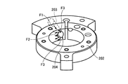
- FIG. 9 is a perspective view for explaining the flow of the refrigerant when sucked into the cylinder from the suction hole in the rotary compressor of the related art.
- the suction hole 203 provided in the cylinder 202 extends along the radial direction of the cylinder 202, the refrigerant flow in the suction hole 203 is a flow F ⁇ b> 1 along the radial direction of the cylinder 202. It becomes.
- the suction hole 203 has a circular opening 204 that penetrates the inner peripheral surface of the cylinder 202, when the refrigerant of the flow F ⁇ b> 1 enters the cylinder 202 from the circular opening 204, the suction hole 203 serves as a piston that rotates in the cylinder 202. Accordingly, the flow changes to a flow including a flow F2 along the circumferential direction of the inner peripheral surface of the cylinder 202 and a flow F3 along the vertical direction (axial direction of the rotation shaft) of the inner peripheral surface of the cylinder 202.
- the refrigerant flowing in the vertical direction of the inner peripheral surface of the cylinder 202 collides with an end plate (including an intermediate partition plate in the case of a two-cylinder rotary compressor) that closes the upper side and the lower side of the cylinder 202.
- an end plate including an intermediate partition plate in the case of a two-cylinder rotary compressor
- a flow such as a vortex is generated and the refrigerant flow in the circumferential direction of the cylinder 202 is obstructed, thereby causing a pressure loss of the refrigerant flowing into the cylinder 202.
- a related-art rotary compressor there is known a configuration in which a notch portion having an arcuate cross section is formed along the vertical direction of the cylinder at the edge of the opening of the suction hole on the inner peripheral surface of the cylinder. Due to this notch, the opening of the suction hole is widened with respect to the circumferential direction of the cylinder, and when the refrigerant enters the cylinder from the opening, the flow of the refrigerant rapidly changes in the vertical direction of the cylinder. To be suppressed.
- the depth of the notch with respect to the radial direction of the cylinder (the radial direction of the rotating shaft) is shallow.
- the effect of alleviating the flow of refrigerant in the vertical direction of the cylinder is poor, and the pressure loss of the refrigerant is insufficiently reduced.
- the disclosed technique has been made in view of the above, and an object of the present invention is to provide a rotary compressor capable of suppressing pressure loss that occurs when a refrigerant is sucked into a cylinder.
- One aspect of the rotary compressor disclosed in the present application is a vertically-placed cylindrical compressor housing that is provided with a refrigerant discharge portion at an upper portion and a refrigerant suction portion at a lower portion, and is sealed, A compression unit that compresses the refrigerant sucked from the suction unit and is discharged from the discharge unit; and a motor that is disposed in the upper part of the compressor housing and drives the compression unit.
- the part includes an annular cylinder, an end plate that closes the upper side and the lower side of the cylinder, a rotating shaft that has an eccentric part and is rotated by the motor, and an inner periphery of the cylinder that is fitted to the eccentric part.
- the suction passage is a cylindrical shape connected to the suction portion.
- a second passage having one end connected to the first passage and the other end opened to the inner peripheral surface of the cylinder. The second passage extends from the one end to the other end.
- FIG. 1 is a longitudinal sectional view showing a rotary compressor of an embodiment.
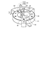
- FIG. 2 is a perspective view showing the compression portion of the rotary compressor of the embodiment from above.
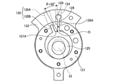
- FIG. 3A is a plan view showing cylinders, pistons, and vanes in the rotary compressor of the embodiment from above.
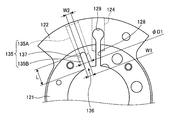
- FIG. 3B is a plan view for explaining the positional relationship between the vane groove and the suction path in the rotary compressor of the embodiment.
- FIG. 4 is a perspective view for explaining the refrigerant flow when sucked into the cylinder from the suction path in the rotary compressor of the embodiment.
- FIG. 5 is a plan view showing cylinders, pistons, and vanes in the rotary compressor according to the first modification from above.
- FIG. 1 is a longitudinal sectional view showing a rotary compressor of an embodiment.
- FIG. 2 is a perspective view showing the compression portion of the rotary compressor of the embodiment from above.
- FIG. 3A is a plan view showing cylinders, pistons,
- FIG. 6 is a plan view showing cylinders, pistons, and vanes in the rotary compressor according to the second modification from above.
- FIG. 7 is a plan view showing cylinders, pistons, and vanes in the rotary compressor of the third modification from above.
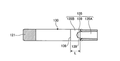
- FIG. 8 is a longitudinal sectional view showing a suction path in the rotary compressor of the fourth modification.
- FIG. 9 is a perspective view for explaining the flow of the refrigerant when sucked into the cylinder from the suction hole in the rotary compressor of the related art.
- FIG. 1 is a longitudinal sectional view showing a rotary compressor of an embodiment.
- FIG. 2 is a perspective view illustrating a compression unit of the rotary compressor according to the embodiment.
- FIG. 3A is a plan view showing cylinders, pistons, and vanes in the rotary compressor of the embodiment from above.
- FIG. 3B is a plan view for explaining the positional relationship between the vane groove and the suction path in the rotary compressor of the embodiment.
- the rotary compressor 1 includes a compression unit 12 disposed at a lower portion in a sealed vertical cylindrical compressor housing 10 and a rotation portion disposed at an upper portion in the compressor housing 10.
- a motor 11 that drives the compression unit 12 via a shaft 15 and a vertically installed cylindrical accumulator 25 that is fixed and sealed to the outer peripheral surface of the compressor housing 10 are provided.
- the accumulator 25 is connected to a cylinder chamber 130 (see FIG. 2) of the cylinder 121 through a suction pipe 105 as a suction portion and an accumulator bending pipe 31.
- the motor 11 includes a stator 111 disposed on the outside and a rotor 112 disposed on the inside.
- the stator 111 is fixed to the inner peripheral surface of the compressor housing 10 in a shrink-fitted state.
- the rotor 112 is fixed to the rotating shaft 15 in a shrink-fitted state.
- the rotary shaft 15 has a secondary shaft portion 151 below the eccentric portion 152 rotatably supported by a secondary bearing portion 161S provided on the lower end plate 160S, and a main shaft portion 153 above the eccentric portion 152 provided on the upper end plate 160T.
- the main bearing portion 161T is rotatably supported, and the eccentric portion 152 is supported by the piston 125, so that the entire compression portion 12 is rotatably supported. Revolve along the circumference.
- lubricating oil 18 for securing the lubricity of sliding parts such as the piston 125 sliding in the compression part 12 and sealing the compression chamber 133 (see FIG. 3A) is compressed.
- the part 12 is enclosed in an amount that substantially immerses the part 12.
- An attachment leg 310 (see FIG. 1) that fixes a plurality of elastic support members (not shown) that support the entire rotary compressor 1 is fixed to the lower side of the compressor housing 10.
- the compressing unit 12 compresses the refrigerant sucked from the suction pipe 105 and discharges it from a discharge pipe 107 serving as a discharge part described later.
- the compression unit 12 is configured by stacking an upper end plate cover 170T, an upper end plate 160T, an annular cylinder 121, and a lower end plate 160S having a bulging portion in which a hollow space is formed inside from above.
- the entire compression unit 12 is fixed by a plurality of through bolts 174 and auxiliary bolts (not shown) arranged substantially concentrically from above and below.
- An upper end plate cover chamber 180 is formed between the upper end plate 160T and the upper end plate cover 170T having a bulging portion.
- the cylinder 121 has an inner peripheral surface along a concentric circle of the rotating shaft 15 of the motor 11. As shown in FIG. A piston 125 having an outer diameter smaller than the inner diameter of the cylinder 121 is disposed inside the inner peripheral surface of the cylinder 121, and the refrigerant is sucked between the inner peripheral surface of the cylinder 121 and the outer peripheral surface of the piston 125. A cylinder chamber 130 for compressing and discharging is formed.
- the cylinder 121 has a side protrusion 122 projecting from a circular outer peripheral portion in the radial direction of the cylinder 121 (the radial direction of the rotating shaft 15).
- the side protrusion 122 is formed over a predetermined protrusion range along the circumferential direction of the rotating shaft 15.
- the side protrusion 122 is used as a chuck holding portion for fixing the cylinder 121 to a processing jig when the cylinder 121 is processed.
- the side protrusion 122 is provided with a vane groove 128 that extends radially from the wall surface of the cylinder chamber 130 toward the outer peripheral side of the cylinder 121.
- a plate-like vane 127 is disposed in the vane groove 128 so as to be slidable in the radial direction of the cylinder 121.
- the lateral protrusion 122 is provided with a spring hole 124 having a depth that does not penetrate the cylinder chamber 130 at a position overlapping the vane groove 128 from the outer peripheral surface of the lateral protrusion 122.
- a spring (not shown) that biases the vane 127 is disposed in the spring hole 124.
- the cylinder 121 introduces the compressed refrigerant in the compressor casing 10 by communicating the radially outer side of the vane groove 128 and the compressor casing 10 through an opening, and the vane is caused by the pressure of the refrigerant.
- a pressure introduction path 129 for applying a back pressure to 127 is formed.
- the cylinder chamber 130 has a discharge chamber provided in the suction chamber 131 and the upper end plate 160T, which communicates with the suction passage 135 when the vane 127 is pressed by the spring and comes into contact with the outer peripheral surface of the piston 125. And a compression chamber 133 communicating with the hole 190.
- the cylinder chamber 130 is closed by the upper end plate 160T on the upper side in the axial direction of the rotary shaft 15, and closed by the lower end plate 160S on the lower side.
- a suction passage 135 connected to the suction pipe 105 is provided in the side protrusion 122 of the cylinder 121 in the radial direction of the cylinder 121 (rotating shaft 15. In the radial direction). Details of the suction passage 135, which is a feature of the present invention, will be described later.
- the upper end plate 160T is provided with a discharge hole 190 that passes through the upper end plate 160T and communicates with the compression chamber 133 of the cylinder 121.
- the discharge hole 190 is disposed in the vicinity of the vane groove 128.
- the refrigerant compressed in the compression chamber 133 is discharged from the compression chamber 133 through the discharge hole 190 into the compressor housing 10.
- An upper valve seat (not shown) is formed around the discharge hole 190 on the outlet side of the discharge hole 190.
- the upper end plate 160T is formed with a discharge valve accommodating recess 164 extending in a groove shape from the position of the discharge hole 190 toward the outer periphery of the upper end plate 160T.
- the discharge valve housing recess 164 includes a reed valve type discharge valve 200 whose rear end is fixed by a rivet (not shown) in the discharge valve housing recess 164 and whose front end opens and closes the discharge hole 190, and a rear end Is superposed on the discharge valve 200 and fixed by a rivet in the discharge valve housing recess 164, and the front end is bent (warped) in the direction in which the discharge valve 200 opens to regulate the opening of the discharge valve 200.
- the entire presser 201 is accommodated.
- the rotation of the rotating shaft 15 causes the piston 125 fitted to the eccentric portion 152 of the rotating shaft 15 to revolve along the inner peripheral surface of the cylinder 121, thereby increasing the volume of the suction chamber 131.
- the discharge valve 200 is opened and the refrigerant is discharged from the compression chamber 133 to the upper end plate cover chamber 180.
- the refrigerant discharged into the upper end plate cover chamber 180 is discharged into the compressor housing 10 from an upper end plate cover discharge hole 172 (see FIG. 1) provided in the upper end plate cover 170T.
- the refrigerant discharged into the compressor housing 10 is notched (not shown) provided on the outer periphery of the stator 111 and communicated with the upper and lower sides, or a gap (not shown) between winding portions of the stator 111, or the stator 111. Is guided to the upper side of the motor 11 through a gap 115 (see FIG. 1) between the rotor 112 and the rotor 112, and is discharged from a discharge pipe 107 serving as a discharge portion disposed on the upper portion of the compressor housing 10.
- the suction passage 135 of the cylinder 121 in the embodiment has a cylindrical first passage 135A connected to a suction pipe 105 as a suction portion, and one end of the first passage 135A. And a second passage 135B having the other end opened to the inner peripheral surface of the cylinder 121.
- the first passage 135 ⁇ / b> A and the second passage 135 ⁇ / b> B extend along the radial direction of the cylinder 121.
- the second passage 135B is formed in a slit shape penetrating the upper end surface and the lower end surface of the cylinder 121 from one end to the other end. That is, the entire second passage 135 ⁇ / b> B penetrates the cylinder 121 in the vertical direction (the axial direction of the rotating shaft 15).
- the second passage 135B has a width at the other end with respect to the circumferential direction of the cylinder 121 as W1, and a length from one end to the other end of the second passage 135B as L. L ⁇ W1 (Formula 1) Meet.
- the width W2 at one end of the second passage 135B (the first passage 135A side) is: W2 ⁇ D1 (Formula 3) Meet.
- the width W1 at the other end of the second passage 135B is such that the inner diameter of the inner surface of the cylinder 121 is Dc and the outer diameter of the outer surface of the piston 125 is Dp. [(Dc ⁇ Dp) ⁇ 0.3] ⁇ W1 ⁇ [(Dc ⁇ Dp) ⁇ 0.7] (Formula 4) Meet.
- the second passage 135 ⁇ / b> B includes a side surface 128 ⁇ / b> A on the suction path 135 side in the vane groove 128 and an inner peripheral surface 121 ⁇ / b> A of the cylinder 121 in a plane orthogonal to the axial direction of the rotation shaft 15.
- the second passage 135B is formed at a position where the central angle ⁇ is 30 degrees or more away from the side surface 128A toward the suction path 135 side with the intersection point as the center O.
- the second passage 135B is arranged so as not to overlap with a fan-shaped region having a central angle ⁇ of 30 degrees around the center O on a plane orthogonal to the axial direction of the rotating shaft 15.
- FIG. 4 is a perspective view for explaining the flow of the refrigerant when sucked into the suction chamber 131 from the suction path 135 in the rotary compressor 1 of the embodiment.
- the refrigerant when the refrigerant is sucked into the suction chamber 131 through the suction passage 135, the refrigerant flows into the second passage 135B from the first passage 135A of the suction passage 135, so that the second passage In 135B, the flow of the refrigerant is spread in advance in the vertical direction of the cylinder 121 (the axial direction of the rotating shaft 15), and rectifies and flows along the upper end plate 160T and the lower end plate 160S in the second passage 135B. For this reason, as shown in FIG.
- the refrigerant sucked into the suction chamber 131 from the opening 136 of the second passage 135 ⁇ / b> B flows along the vertical direction of the inner peripheral surface of the cylinder 121 at the edge of the opening 136. Occurrence is suppressed, and a flow F2 along the circumferential direction of the inner peripheral surface of the cylinder 121 is generated from the opening 136 of the second passage 135B.
- the refrigerant flows along the vertical direction of the inner peripheral surface of the cylinder 121 at the edge of the opening 136 of the second passage 135B. Therefore, the flow of the refrigerant along the circumferential direction of the inner peripheral surface of the cylinder 121 is prevented from being obstructed, and the pressure loss of the refrigerant at the edge of the opening 136 is reduced, so that the rotary compressor 1 is compressed. Efficiency is increased.
- the rate of change of the volume in the suction chamber 131 is greatly different during one rotation of the piston 125, so the flow rate of the refrigerant flowing in the suction passage 135 is greatly changed during one rotation of the piston 125.
- a supercharging phenomenon in which the pressure in the suction chamber 131 becomes larger than the pressure in the suction path 135 due to the inertial force (momentum) of the refrigerant flowing in the suction path 135 occurs. The effect of improving the circulation flow rate is obtained.
- the opening 136 of the second passage 135 ⁇ / b> B of the suction passage 135 is a circumferential opening of the cylinder chamber 130 as compared to the opening when the inner diameter D ⁇ b> 1 of the cylindrical first passage 135 ⁇ / b> A is extended to the inner peripheral surface of the cylinder 121.
- the width becomes narrower.
- the opening 136 of the second passage 135B has the position of the opening edge in the circumferential direction of the cylinder 121 (the angle at which the inner peripheral surface of the cylinder 121 and the second passage 135B are connected) It is far from the position in the circumferential direction of the suction chamber 131, that is, the position where the outer peripheral surface of the piston 125 and the inner peripheral surface of the cylinder 121 are in sliding contact.
- the refrigerant sucked into the suction chamber 131 hits the back position in the circumferential direction of the suction chamber 131 and is returned from the suction chamber 131. Backflow into the suction passage 135 through 136 is suppressed.
- the opening area of the second passage 135B of the suction path 135 is small with respect to the flow rate of the refrigerant, the inflow resistance to the suction chamber 131 is increased, and thus pressure loss occurs.
- the opening area of the opening 136 communicating with the suction chamber 131 in the suction path 135 is large, the flow rate of the refrigerant supercharged in the suction chamber 131 flows back to the suction path 135 side increases, and the above-described refrigerant The effect of improving the circulation flow rate is negated.
- the opening area of the opening 136 of the second passage 135B is not only increased in order to reduce the inflow resistance to the suction chamber 131, but also in order to suppress the reverse flow of the refrigerant supercharged in the suction chamber 131.
- the width W1 of the second passage 135B penetrating in the vertical direction of the cylinder 121 (the axial direction of the rotary shaft 15) is optimized by satisfying Expression 4, and when the refrigerant is sucked into the suction chamber 131 from the second passage 135B. Since the generated pressure loss is reduced and the flow rate of the refrigerant temporarily supercharged into the suction chamber 131 during the suction of the refrigerant into the cylinder 121 can be suppressed, the rotary compressor can be suppressed. 1 compression efficiency can be increased.
- the suction passage 135 of the rotary compressor 1 of the embodiment includes the first passage 135A and the slit-like second passage 135B, and the second passage 135B has L ⁇ W1 and W1 ⁇ D1 ⁇ . 0.7 and W2 ⁇ D1 are satisfied.
- the disturbance of the refrigerant flow in the second passage 135B is suppressed, and when the refrigerant is sucked into the suction chamber 131 from the second passage 135B, the refrigerant flowing along the vertical direction of the inner peripheral surface of the cylinder 121 is reduced. Since the generation of the flow is suppressed, the pressure loss of the refrigerant flow sucked into the suction chamber 131 can be reduced.
- the amount of the refrigerant once sucked into the suction chamber 131 flows back and returns to the suction path 135 can be effectively reduced. Therefore, the compression efficiency of the rotary compressor 1 can be increased.
- the width W1 at the other end of the second passage 135B is W1 ⁇ [(Dc ⁇ Dp) ⁇ 0.3]
- the pressure loss of the refrigerant flow in the second passage increases
- W1 ⁇ [(Dc ⁇ Dp) ⁇ 0.7] the refrigerant once sucked into the suction chamber 131 is The amount of backflow and return to the suction path 135 increases.
- the width W1 of the second passage 135B is optimized and sucked into the suction chamber 131.
- the pressure loss of the refrigerant flow is effectively reduced, and the flow rate of the refrigerant temporarily supercharged into the suction chamber 131 during the suction of the refrigerant into the cylinder 121 is suppressed to the suction path 135. Therefore, the compression efficiency of the rotary compressor 1 can be increased.
- the pressure in the compression chamber 133 is higher than the pressure in the suction chamber 131. Therefore, the vane 127 tends to be pushed toward the suction chamber 131 due to the pressure difference between the compression chamber 133 and the suction chamber 131. .
- the vane groove 128 that supports the vane 127 pushed toward the suction chamber 131 due to the pressure difference is pushed by the vane 127 on the side surface 128A on the suction path 135 side. For this reason, when the thickness of the portion between the slit-like second passage 135 ⁇ / b> B penetrating in the vertical direction of the cylinder 121 and the vane groove 128 becomes thin, the rotary compressor 1 may be damaged during operation. .
- the finishing process of the vane groove 128 is a second processing step of the general cylinder 121. This is performed in a later process than the cutting process of the passage 135B. For this reason, when the thickness of the portion between the slit-like second passage 135 ⁇ / b> B penetrating in the vertical direction of the cylinder 121 and the vane groove 128 becomes thin, this portion finished the vane groove 128. It is sometimes deformed, leading to a decrease in compression efficiency of the rotary compressor 1 due to refrigerant leakage due to a decrease in the width dimensional accuracy of the vane groove 128 and an increase in sliding loss due to a decrease in surface roughness.
- the rotary compressor 1 is configured so that the side surface 128A of the vane groove 128 on the suction path 135 side of the vane groove 128 and the inner peripheral surface 121A of the cylinder 121 have a center O as the center O.
- a second passage 135B is formed at a position where the central angle ⁇ is 30 degrees or more away from 128A toward the suction passage 135 side.
- the cylinder 121 can ensure an appropriate thickness between the vane groove 128 and the second passage 135 ⁇ / b> B with respect to the circumferential direction of the cylinder 121.
- the mechanical strength of the portion of the cylinder 121 between the vane groove 128 and the second passage 135B is appropriately ensured, and the machining accuracy of the width dimension of the vane groove 128 is achieved by appropriately finishing the vane groove 128. And surface roughness can be ensured appropriately and the reduction of the compression efficiency of the rotary compressor 1 can be suppressed.
- FIG. 5 is a plan view showing the cylinder 121, the piston 125, and the vane 127 in the rotary compressor according to the first modification from above.
- FIG. 6 is a plan view showing the cylinder 121, the piston 125, and the vane 127 in the rotary compressor according to the second modification from above.
- FIG. 7 is a plan view showing the cylinder 121, the piston 125, and the vane 127 in the rotary compressor according to the third modification from above.
- FIG. 8 is a longitudinal sectional view showing a suction path in the rotary compressor of the fourth modification.
- the refrigerant temporarily supercharged into the suction chamber 131 during the suction of the refrigerant into the cylinder 121 is sucked into the suction passage. Since the effect of suppressing the flow rate flowing back to 135 can be further increased, the compression efficiency of the rotary compressor 1 can be increased. Also in the first modification, similarly to the embodiment, the pressure loss generated in the suction passage 135 when the refrigerant is sucked can be reduced, and the compression efficiency of the rotary compressor 1 can be increased.
- the end surface on the one end side of the second passage 135B is formed with a straight line (plane), but may be formed with an arc (curved surface) as shown in FIG.
- the second passage 135B can be cut using an end mill.
- the suction passage 135 of the rotary compressor according to the modified example 4 is provided at one end of the first passage 135 ⁇ / b> A on the second passage 135 ⁇ / b> B side toward the upper side and the lower side of the cylinder 121.
- a tapered chamfered portion 139 is formed so that the width in the vertical direction (the axial direction of the rotary shaft 15) gradually increases.
- the first passage 135A in the modified example 4 is formed with a chamfered portion 139 at one end connected to the second passage 135B, so that the flow path of the suction passage 135 gradually expands in the vertical direction of the cylinder 121. Therefore, it is possible to further suppress the disturbance of the refrigerant flow in the suction passage 135. Thereby, the pressure loss generated in the suction passage 135 when the refrigerant is sucked can be further reduced, and the compression efficiency of the rotary compressor 1 can be further increased.
- the central angle ⁇ is formed at a position where the central angle ⁇ is 30 degrees or more away from the side surface 128A of the vane groove 128 toward the suction passage 135 as in the embodiment.
- the thickness between the vane groove 128 and the second passage 135B is ensured to an appropriate thickness.
- the present invention is not limited to the embodiments and the modifications, and for example, a two-cylinder rotary compressor having two cylinders arranged with an intermediate partition plate corresponding to an end plate for closing the cylinder interposed therebetween. May be applied.
- a two-cylinder rotary compressor the refrigerant sucked into one of the cylinders being sucked tends to be pulled by the pressure toward the other cylinder while being compressed through the accumulator and sucked into the suction chamber. Refrigerant tends to flow backward from the suction path.
- the configuration related to the suction passage 135 of the above-described embodiment and the modification is applied to a two-cylinder rotary compressor, the effect is higher than that of the one-cylinder rotary compressor.
- the embodiment has been described above, but the embodiment is not limited by the above-described content.
- the above-described constituent elements include those that can be easily assumed by those skilled in the art, those that are substantially the same, and those in a so-called equivalent range.
- the above-described components can be appropriately combined.
- at least one of various omissions, substitutions, and changes of the components can be made without departing from the scope of the embodiments.
Landscapes
- Engineering & Computer Science (AREA)
- Mechanical Engineering (AREA)
- General Engineering & Computer Science (AREA)
- Applications Or Details Of Rotary Compressors (AREA)
Abstract
吸入路(135)は、吸入部(105)に接続された円筒状の第1通路(135A)と、一端が第1通路(135A)に接続され他端がシリンダ(121)の内周面に開口した第2通路(135B)と、を有する。第2通路(135B)は、一端から他端に亘ってシリンダ(121)の上側と下側とに貫通するスリット状に形成され、第2通路(135B)の他端における、シリンダ(121)の周方向に対する幅をW1、第2通路(135B)の一端における幅をW2、第2通路(135B)の一端から他端までの長さをL、第2通路(135B)との接続部における第1通路(135A)の内径をD1としたとき、L≧W1、W1≦D1×0.7、W2≦D1を満たす。
Description
本発明は、ロータリ圧縮機に関する。
ロータリ圧縮機では、環状のシリンダの径方向に沿って延びる円筒状の吸入孔を通して、シリンダ内に冷媒が吸入され、シリンダ内で偏心回転する環状のピストンによって冷媒が圧縮される。
図9は、関連技術のロータリ圧縮機において、吸入孔からシリンダ内に吸入されるときの冷媒の流れを説明するための斜視図である。図9に示すように、シリンダ202に設けられた吸入孔203は、シリンダ202の径方向に沿って延びているので、吸入孔203内における冷媒の流れが、シリンダ202の径方向に沿う流れF1となる。吸入孔203は、シリンダ202の内周面に貫通する円形状の開口204を有するので、流れF1の冷媒が円形状の開口204からシリンダ202内へ入るときに、シリンダ202内で回転するピストンに伴い、シリンダ202の内周面の周方向へ沿う流れF2と、シリンダ202の内周面の上下方向(回転軸の軸方向)へ沿う流れF3とを含む流れに変化する。このとき、特にシリンダ202の内周面の上下方向へ流れる冷媒は、シリンダ202の上側と下側をそれぞれ塞ぐ端板(2シリンダ型のロータリ圧縮機の場合には中間仕切板を含む)に衝突して渦等の流れが発生し、シリンダ202の周方向に対する冷媒の流れを妨げることにより、シリンダ202内に流入する冷媒の圧力損失が生じる問題がある。
関連技術のロータリ圧縮機としては、シリンダの内周面における吸入孔の開口の縁部に、断面円弧状の切り欠き部が、シリンダの上下方向に沿って形成された構成等が知られている。この切り欠き部により、吸入孔の開口は、シリンダの周方向に対して広げられており、開口からシリンダ内に冷媒が入るときに、冷媒の流れが、シリンダの上下方向に向かって急激に変化することが抑制されている。
しかしながら、このように吸入孔の開口に切り欠き部が形成された構成であっても、シリンダの径方向(回転軸の径方向)に対する切り欠き部の深さが浅いので、吸入孔の開口からシリンダの上下方向へ向かう冷媒の流れを緩和する作用が乏しく、冷媒の圧力損失の低減が不十分である。
開示の技術は、上記に鑑みてなされたものであって、シリンダ内に冷媒を吸入するときに生じる圧力損失を抑制することができるロータリ圧縮機を提供することを目的とする。
本願の開示するロータリ圧縮機の一態様は、上部に冷媒の吐出部が設けられ下部に冷媒の吸入部が設けられ密閉された縦置き円筒状の圧縮機筐体と、前記圧縮機筐体内の下部に配置され前記吸入部から吸入された冷媒を圧縮し前記吐出部から吐出する圧縮部と、前記圧縮機筐体内の上部に配置され前記圧縮部を駆動するモータと、を有し、前記圧縮部は、環状のシリンダと、前記シリンダの上側及び下側をそれぞれ閉塞する端板と、偏心部を有し前記モータにより回転される回転軸と、前記偏心部に嵌合され前記シリンダの内周面に沿って公転し前記シリンダ内にシリンダ室を形成するピストンと、前記シリンダに設けられたベーン溝から前記シリンダ室内に突出し前記ピストンと当接することで前記シリンダ室を吸入室と圧縮室に区画するベーンと、前記シリンダに当該シリンダの径方向に延びて設けられ前記吸入部に連通された冷媒の吸入路と、を有するロータリ圧縮機において、前記吸入路は、前記吸入部に接続された円筒状の第1通路と、一端が前記第1通路に接続され他端が前記シリンダの内周面に開口した第2通路と、を有し、前記第2通路は、前記一端から前記他端に亘って前記シリンダの上側と下側とに貫通するスリット状に形成され、前記第2通路の前記他端における、前記シリンダの周方向に対する幅をW1、前記第2通路の前記一端における前記幅をW2、前記第2通路の前記一端から前記他端までの長さをL、前記第2通路との接続部における前記第1通路の内径をD1としたとき、L≧W1、W1≦D1×0.7、W2≦D1を満たす。
本願の開示するロータリ圧縮機の一態様によれば、シリンダ内に冷媒を吸入するときに生じる圧力損失を抑制することができる。
以下に、本願の開示するロータリ圧縮機の実施例を図面に基づいて詳細に説明する。なお、以下の実施例によって、本願の開示するロータリ圧縮機が限定されるものではない。
(ロータリ圧縮機の構成)
図1は、実施例のロータリ圧縮機を示す縦断面図である。図2は、実施例のロータリ圧縮機の圧縮部を示す斜視図である。図3Aは、実施例のロータリ圧縮機におけるシリンダ、ピストン、ベーンを上方から示す平面図である。図3Bは、実施例のロータリ圧縮機におけるベーン溝と吸入路との位置関係を説明するための平面図である。
図1は、実施例のロータリ圧縮機を示す縦断面図である。図2は、実施例のロータリ圧縮機の圧縮部を示す斜視図である。図3Aは、実施例のロータリ圧縮機におけるシリンダ、ピストン、ベーンを上方から示す平面図である。図3Bは、実施例のロータリ圧縮機におけるベーン溝と吸入路との位置関係を説明するための平面図である。
図1に示すように、ロータリ圧縮機1は、密閉された縦置き円筒状の圧縮機筐体10内の下部に配置された圧縮部12と、圧縮機筐体10内の上部に配置され回転軸15を介して圧縮部12を駆動するモータ11と、圧縮機筐体10の外周面に固定され密閉された縦置き円筒状のアキュムレータ25と、を備えている。
アキュムレータ25は、吸入部としての吸入管105及びアキュムレータ湾曲管31を介してシリンダ121のシリンダ室130(図2参照)と接続されている。
モータ11は、外側に配置されたステータ111と、内側に配置されたロータ112と、を備えている。ステータ111は、圧縮機筐体10の内周面に焼嵌め状態で固定されている。ロータ112は、回転軸15に焼嵌め状態で固定されている。
回転軸15は、偏心部152の下方の副軸部151が、下端板160Sに設けられた副軸受部161Sに回転自在に支持され、偏心部152の上方の主軸部153が上端板160Tに設けられた主軸受部161Tに回転自在に支持され、偏心部152にピストン125が支持されることによって、圧縮部12全体に対して回転自在に支持されるとともに、回転によってピストン125をシリンダ121の内周面に沿って公転運動させる。
圧縮機筐体10の内部には、圧縮部12において摺動するピストン125等の摺動部の潤滑性を確保し、圧縮室133(図3A参照)をシールするための潤滑油18が、圧縮部12をほぼ浸漬する量だけ封入されている。圧縮機筐体10の下側には、ロータリ圧縮機1全体を支持する複数の弾性支持部材(図示せず)を係止する取付脚310(図1参照)が固定されている。
図1に示すように、圧縮部12は、吸入管105から吸入された冷媒を圧縮し、後述する吐出部としての吐出管107から吐出する。圧縮部12は、上から、内部に中空空間が形成された膨出部を有する上端板カバー170T、上端板160T、環状のシリンダ121及び下端板160Sを積層して構成されている。圧縮部12全体は、上下から略同心円上に配置された複数の通しボルト174及び補助ボルト(図示せず)によって固定されている。互いに密着固定された上端板160Tと、膨出部を有する上端板カバー170Tとの間には、上端板カバー室180が形成される。
図3A及び図3Bに示すように、シリンダ121には、モータ11の回転軸15の同心円上に沿って内周面が形成されている。シリンダ121の内周面の内側には、シリンダ121の内径よりも小さい外径のピストン125が配置されており、シリンダ121の内周面とピストン125の外周面との間に、冷媒を吸入し圧縮して吐出するシリンダ室130が形成される。
図2、図3A及び図3Bに示すように、シリンダ121は、円形状の外周部から、シリンダ121の径方向(回転軸15の径方向)に張り出した側方突出部122を有する。側方突出部122は、回転軸15の周方向に沿って、所定の突出範囲にわたって形成されている。側方突出部122は、シリンダ121の加工時にシリンダ121を加工治具に固定するためのチャック用保持部として用いられる。
側方突出部122には、シリンダ室130の壁面から放射状にシリンダ121の外周側へ延びるベーン溝128が設けられている。ベーン溝128内には、板状のベーン127がシリンダ121の径方向に摺動可能に配置されている。側方突出部122には、側方突出部122の外周面から、ベーン溝128と重なる位置に、シリンダ室130に貫通しない深さのスプリング穴124が設けられている。スプリング穴124内には、ベーン127を付勢するスプリング(図示せず)が配置されている。
また、シリンダ121には、ベーン溝128の径方向外側と圧縮機筐体10内とを開口部で連通して圧縮機筐体10内の圧縮された冷媒を導入し、冷媒の圧力により、ベーン127に対して背圧をかける圧力導入路129が形成されている。
図3Aに示すように、シリンダ室130は、ベーン127がスプリングに押圧されてピストン125の外周面に当接することによって、吸入路135に連通する吸入室131と、上端板160Tに設けられた吐出孔190に連通する圧縮室133と、に区画される。シリンダ室130は、回転軸15の軸方向における上側を上端板160Tで閉塞されており、下側を下端板160Sで閉塞されている。
また、図1、図2、図3A及び図3Bに示すように、シリンダ121の側方突出部122には、吸入管105と接続される吸入路135が、シリンダ121の径方向(回転軸15の径方向)に延びて設けられている。本発明の特徴点となる吸入路135の詳細については後述する。
上端板160Tには、図1に示すように、上端板160Tを貫通してシリンダ121の圧縮室133と連通する吐出孔190が設けられている。吐出孔190は、ベーン溝128に近接して配置されている。圧縮室133内で圧縮された冷媒は、圧縮室133内から、吐出孔190を通って、圧縮機筐体10内へ吐出される。吐出孔190の出口側には、吐出孔190の周囲に上弁座(図示せず)が形成されている。上端板160Tには、吐出孔190の位置から上端板160Tの外周に向かって溝状に延びる吐出弁収容凹部164が形成されている。
吐出弁収容凹部164には、後端部が吐出弁収容凹部164内にリベット(図示せず)により固定されて前端部が吐出孔190を開閉するリード弁型の吐出弁200と、後端部が吐出弁200に重ねられて吐出弁収容凹部164内にリベットにより固定されて前端部が、吐出弁200が開く方向へ湾曲して(反って)いて吐出弁200の開度を規制する吐出弁押さえ201全体とが収容されている。
以下に、回転軸15の回転による冷媒の流れを説明する。シリンダ室130内において、回転軸15の回転によって、回転軸15の偏心部152に嵌合されたピストン125が、シリンダ121の内周面に沿って公転することにより、吸入室131が容積を拡大しながら吸入管105から冷媒を吸入し、圧縮室133が容積を縮小しながら冷媒を圧縮し、圧縮した冷媒の圧力が吐出弁200の外側の上端板カバー室180の圧力より高くなると、吐出弁200が開いて圧縮室133から上端板カバー室180へ冷媒が吐出される。上端板カバー室180に吐出された冷媒は、上端板カバー170Tに設けられた上端板カバー吐出孔172(図1参照)から圧縮機筐体10内に吐出される。
圧縮機筐体10内に吐出された冷媒は、ステータ111外周に設けられた上下に連通する切欠き(図示せず)、又はステータ111の巻線部の隙間(図示せず)、又はステータ111とロータ112との隙間115(図1参照)を通ってモータ11の上方に導かれ、圧縮機筐体10の上部に配置された吐出部としての吐出管107から吐出される。
(ロータリ圧縮機の特徴的な構成)
次に、実施例のロータリ圧縮機1の特徴的な構成について説明する。実施例におけるシリンダ121の吸入路135は、図2、図3A及び図3Bに示すように、吸入部としての吸入管105に接続された円筒状の第1通路135Aと、一端が第1通路135Aに接続され他端がシリンダ121の内周面に開口した第2通路135Bと、を有する。第1通路135A及び第2通路135Bは、シリンダ121の径方向に沿って延びている。
次に、実施例のロータリ圧縮機1の特徴的な構成について説明する。実施例におけるシリンダ121の吸入路135は、図2、図3A及び図3Bに示すように、吸入部としての吸入管105に接続された円筒状の第1通路135Aと、一端が第1通路135Aに接続され他端がシリンダ121の内周面に開口した第2通路135Bと、を有する。第1通路135A及び第2通路135Bは、シリンダ121の径方向に沿って延びている。
第2通路135Bは、一端から他端に亘ってシリンダ121の上側端面と下側端面とにそれぞれ貫通するスリット状に形成されている。すなわち、第2通路135B全体は、シリンダ121の上下方向(回転軸15の軸方向)に亘って貫通している。第2通路135Bは、シリンダ121の周方向に対する幅が、一端から他端に亘って等しい、すなわちシリンダ121の径方向に亘って幅が等しいストレート状に形成されている(W1=W2)。このため、第2通路135Bの他端は、シリンダ121の内周面上で、上端板160Tと下端板160Sとの間に亘って連続する矩形状の開口136を有する。
そして、第2通路135Bは、他端における、シリンダ121の周方向に対する幅をW1、第2通路135Bの一端から他端までの長さをLとしたとき、
L≧W1 ・・・(式1)
を満たす。
L≧W1 ・・・(式1)
を満たす。
また、第1通路135Aの内径(直径)をD1としたとき、
W1≦D1×0.7 ・・・(式2)
を満たす。なお、第2通路135Bとの接続部における第1通路135Aの内径D1が、式2を満たしていればよい。
W1≦D1×0.7 ・・・(式2)
を満たす。なお、第2通路135Bとの接続部における第1通路135Aの内径D1が、式2を満たしていればよい。
また、第2通路135Bの一端(第1通路135A側)における幅W2は、
W2≦D1 ・・・(式3)
を満たす。
W2≦D1 ・・・(式3)
を満たす。
また、図3Aに示すように、第2通路135Bの他端における幅W1は、シリンダ121の内周面の内径をDc、ピストン125の外周面の外径をDpとしたとき、
[(Dc-Dp)×0.3]≦W1≦[(Dc-Dp)×0.7] ・・・(式4)
を満たす。
[(Dc-Dp)×0.3]≦W1≦[(Dc-Dp)×0.7] ・・・(式4)
を満たす。
加えて、第2通路135Bは、図3Bに示すように、回転軸15の軸方向に直交する平面において、ベーン溝128における吸入路135側の側面128Aと、シリンダ121の内周面121Aとの交点を中心Oとして、側面128Aから吸入路135側へ向かって中心角θが30度以上離れた位置に、第2通路135Bが形成されている。言い換えると、第2通路135Bは、回転軸15の軸方向に直交する平面において、中心O回りに中心角θが30度をなす扇状の領域に重ならないように配置されている。
以上のように構成された実施例のロータリ圧縮機1について、シリンダ121内における冷媒の流れと本実施例による効果を説明する。図4は、実施例のロータリ圧縮機1において、吸入路135から吸入室131内に吸入されるときの冷媒の流れを説明するための斜視図である。
実施例のロータリ圧縮機1では、吸入路135を通して吸入室131内に冷媒が吸入される際、吸入路135の第1通路135Aから第2通路135B内へ冷媒が流入することで、第2通路135B内で冷媒の流れがシリンダ121の上下方向(回転軸15の軸方向)に予め広げられ、第2通路135B内を上端板160T及び下端板160Sに沿って整流されて流れる。このため、図4に示すように、第2通路135Bの開口136から吸入室131内へ吸入される冷媒は、開口136の縁部でシリンダ121の内周面の上下方向へ沿う冷媒の流れが生じることが抑えられ、第2通路135Bの開口136から、シリンダ121の内周面の周方向へ沿う流れF2となる。
このように、第2通路135Bがシリンダ121の上下方向に貫通することにより、第2通路135Bの開口136の縁部で、シリンダ121の内周面の上下方向へ沿う冷媒の流れが生じることが抑制されるので、シリンダ121の内周面の周方向へ沿う冷媒の流れが妨げられることが抑えられ、開口136の縁部で冷媒の圧力損失が生じることを低減し、ロータリ圧縮機1の圧縮効率が高められる。
ところで、ロータリ圧縮機1では、吸入室131内の容積の変化率が、ピストン125の1回転中において大きく異なるので、吸入路135内を流れる冷媒の流速が、ピストン125の1回転中に大きく変化する。特に、高速回転時には、吸入路135内を流れる冷媒の慣性力(勢い)により、吸入路135内の圧力よりも吸入室131内の圧力が大きくなる過給現象が生じて、過給現象により冷媒の循環流量が向上する効果が得られる。
しかしながら、吸入室131内への冷媒の吸入が完了するタイミングでは、吸入室131の容積の変化率が小さいので、冷媒の流速が遅くなり、吸入路135から吸入室131への冷媒の吸入途中で一時的に、吸入室131内に過給された冷媒が、吸入路135側へ逆流してしまう。
吸入路135の第2通路135Bの開口136は、円筒状の第1通路135Aの内径D1をシリンダ121の内周面まで延ばされた場合の開口と比べて、シリンダ室130の周方向の開口幅が狭くなる。このように開口幅が狭くなることで、第2通路135Bの開口136は、シリンダ121の周方向における開口縁(シリンダ121の内周面と第2通路135Bとが接続する角)の位置が、吸入室131の周方向における奥の位置、つまり、ピストン125の外周面とシリンダ121の内周面とが摺接する位置から遠くなる。これにより、吸入室131内への冷媒の吸入が完了するタイミングで、吸入室131内へ吸入された冷媒が、吸入室131の周方向における奥の位置に突き当たって戻され、吸入室131から開口136を通って吸入路135内へ逆流することが抑えられる。
また、吸入路135の第2通路135Bの開口136は、冷媒の流量に対して開口面積が小さい場合、吸入室131への流入抵抗が大きくなるので圧力損失が発生してしまう。その一方で、吸入路135における吸入室131へ連通する開口136の開口面積が大きい場合、吸入室131内に過給された冷媒が吸入路135側へ逆流する流量が大きくなり、上述した冷媒の循環流量を向上する効果が打ち消されてしまう。したがって、第2通路135Bの開口136の開口面積は、吸入室131への流入抵抗を小さくするために大きくするだけでなく、吸入室131に過給された冷媒の逆流を抑えるために、適正な寸法範囲に設定する必要がある。
シリンダ121の上下方向(回転軸15の軸方向)に貫通する第2通路135Bの幅W1は、式4を満たすことで適正化され、第2通路135Bから吸入室131内への冷媒の吸入時に生じる圧力損失を低減するとともに、シリンダ121内への冷媒の吸入途中で一時的に吸入室131に過給された冷媒が、吸入路135へ逆流する流量を抑制することができるので、ロータリ圧縮機1の圧縮効率を高めることができる。
上述したように実施例のロータリ圧縮機1が有する吸入路135は、第1通路135Aと、スリット状の第2通路135Bとを有し、第2通路135Bが、L≧W1、W1≦D1×0.7、W2≦D1を満たす。これにより、第2通路135B内での冷媒の流れの乱れが抑えられ、さらに第2通路135Bから吸入室131内へ冷媒が吸入されるときにシリンダ121の内周面の上下方向へ沿う冷媒の流れが生じることが抑えられるので、吸入室131へ吸入される冷媒の流れの圧力損失を低減することができる。また、一度吸入室131へ吸入された冷媒が逆流して吸入路135へ戻る量を効果的に低減することができる。したがって、ロータリ圧縮機1の圧縮効率を高めることができる。
また、実施例のロータリ圧縮機1において、シリンダ121の内径をDc、ピストン125の外径をDpとしたとき、第2通路135Bの他端における幅W1は、W1≦[(Dc-Dp)×0.3]の場合には第2通路での冷媒の流れの圧力損失が大きくなり、W1≧[(Dc-Dp)×0.7]の場合には一度吸入室131へ吸入された冷媒が逆流して吸入路135へ戻る量が大きくなる。したがって、[(Dc-Dp)×0.3]≦W1≦[(Dc-Dp)×0.7]を満たすことにより、第2通路135Bの幅W1は適正化され、吸入室131へ吸入される冷媒の流れの圧力損失を効果的に低減するとともに、シリンダ121内への冷媒の吸入途中で一時的に吸入室131に過給された冷媒が、吸入路135へ逆流する流量を抑制することができるので、ロータリ圧縮機1の圧縮効率を高めることができる。
一般にロータリ圧縮機1では、圧縮室133内の圧力が吸入室131内の圧力よりも高いので、圧縮室133と吸入室131との圧力差によってベーン127が吸入室131側へ押される傾向がある。このとき、圧力差により吸入室131側へ押されるベーン127を支持するベーン溝128は、吸入路135側の側面128Aがベーン127によって押される。このため、シリンダ121の上下方向に貫通するスリット状の第2通路135Bと、ベーン溝128との間の部分の肉厚が薄くなった場合、ロータリ圧縮機1の運転中に破損するおそれがある。
また、ベーン溝128は、シリンダ121の周方向に対する幅寸法及び側面の面粗度の加工精度に対する要求が高いため、一般的なシリンダ121の加工工程として、ベーン溝128の仕上げ加工が、第2通路135Bの切削加工よりも後工程で行われている。このため、シリンダ121の上下方向に貫通するスリット状の第2通路135Bと、ベーン溝128との間の部分の肉厚が薄くなった場合、この部分が、ベーン溝128の仕上げ加工を行ったときに変形してしまい、ベーン溝128の幅寸法精度の低下による冷媒の漏れ、及び面粗度の低下による摺動損失の増加により、ロータリ圧縮機1の圧縮効率の低下につながる。
実施例のロータリ圧縮機1は、回転軸15の軸方向の直交する平面において、ベーン溝128における吸入路135側の側面128Aと、シリンダ121の内周面121Aとの交点を中心Oとして、側面128Aから吸入路135側へ向かって中心角θが30度以上離れた位置に、第2通路135Bが形成されている。これにより、シリンダ121は、シリンダ121の周方向に対して、ベーン溝128と第2通路135Bとの間の肉厚を適正な厚みに確保することができる。したがって、シリンダ121におけるベーン溝128と第2通路135Bとの間の部分の機械的強度を適正に確保すると共に、ベーン溝128の仕上げ加工を適正に行うことによりベーン溝128の幅寸法の加工精度及び面粗度を適正に確保し、ロータリ圧縮機1の圧縮効率の低下を抑制することができる。
以下、変形例について図面を参照して説明する。変形例において、実施例と同一の構成部材には、実施例と同一の符号を付して説明を省略する。
図5は、変形例1のロータリ圧縮機におけるシリンダ121、ピストン125、ベーン127を上方から示す平面図である。図6は、変形例2のロータリ圧縮機におけるシリンダ121、ピストン125、ベーン127を上方から示す平面図である。図7は、変形例3のロータリ圧縮機におけるシリンダ121、ピストン125、ベーン127を上方から示す平面図である。図8は、変形例4のロータリ圧縮機における吸入路を示す縦断面図である。
(変形例1)
上述した実施例では、第2通路135Bは、シリンダ121の周方向に対する幅が、一端から他端に亘って等しい、すなわちシリンダ121の径方向に亘って幅が等しいストレート状に形成されていたが、式2(W1≦D1×0.7)かつ式3(W2≦D1)を満たせば、ストレート状(W1=W2)に限定するものでなく、図5に示すようにテーパ状(W1<W2)でもよい。第2通路135Bを冷媒の流れに対して下流側(開口136側)を細くすることにより、シリンダ121内への冷媒の吸入途中で一時的に吸入室131に過給された冷媒が、吸入路135へ逆流する流量を抑制する効果をより大きくすることができるので、ロータリ圧縮機1の圧縮効率を高めることができる。また、変形例1においても、実施例と同様に、冷媒を吸入するときに吸入路135で生じる圧力損失を低減し、ロータリ圧縮機1の圧縮効率を高めることができる。
上述した実施例では、第2通路135Bは、シリンダ121の周方向に対する幅が、一端から他端に亘って等しい、すなわちシリンダ121の径方向に亘って幅が等しいストレート状に形成されていたが、式2(W1≦D1×0.7)かつ式3(W2≦D1)を満たせば、ストレート状(W1=W2)に限定するものでなく、図5に示すようにテーパ状(W1<W2)でもよい。第2通路135Bを冷媒の流れに対して下流側(開口136側)を細くすることにより、シリンダ121内への冷媒の吸入途中で一時的に吸入室131に過給された冷媒が、吸入路135へ逆流する流量を抑制する効果をより大きくすることができるので、ロータリ圧縮機1の圧縮効率を高めることができる。また、変形例1においても、実施例と同様に、冷媒を吸入するときに吸入路135で生じる圧力損失を低減し、ロータリ圧縮機1の圧縮効率を高めることができる。
(変形例2)
また、上述した実施例では、第2通路135Bの一端側の端面は直線(平面)で形成されたが、図6に示すように円弧(曲面)で形成されてもよい。第2通路135Bの一端側を円弧状に形成することにより、第2通路135Bをエンドミルを用いて切削加工することができる。
また、上述した実施例では、第2通路135Bの一端側の端面は直線(平面)で形成されたが、図6に示すように円弧(曲面)で形成されてもよい。第2通路135Bの一端側を円弧状に形成することにより、第2通路135Bをエンドミルを用いて切削加工することができる。
(変形例3)
さらに、図7に示すように、第2通路135Bの一端側を形成する円弧の直径をD2としたとき、直径D2は第2通路135Bの一端側の幅W2に相当すると考えられので、式3はD2≦D1と置き換えられ、D2≦D1を満たす範囲において、円弧の直径D2を第2通路135Bのスリット部Sの幅よりも大きくしてもよい。第2通路135Bの一端側を形成する円弧の直径D2を第2通路135Bのスリット部Sの幅よりも大きくすることにより、第2通路135Bのスリット部Sをブローチ加工で形成する場合に、円弧部が逃げ部となりブローチ加工を容易にすることができる。
さらに、図7に示すように、第2通路135Bの一端側を形成する円弧の直径をD2としたとき、直径D2は第2通路135Bの一端側の幅W2に相当すると考えられので、式3はD2≦D1と置き換えられ、D2≦D1を満たす範囲において、円弧の直径D2を第2通路135Bのスリット部Sの幅よりも大きくしてもよい。第2通路135Bの一端側を形成する円弧の直径D2を第2通路135Bのスリット部Sの幅よりも大きくすることにより、第2通路135Bのスリット部Sをブローチ加工で形成する場合に、円弧部が逃げ部となりブローチ加工を容易にすることができる。
(変形例4)
図8に示すように、変形例4のロータリ圧縮機の吸入路135は、第1通路135Aにおける第2通路135B側の一端に、シリンダ121の上側と下側に向かって、第1通路135Aの上下方向(回転軸15の軸方向)の幅が徐々に拡大するようにテーパ状の面取り部139が形成されている。
図8に示すように、変形例4のロータリ圧縮機の吸入路135は、第1通路135Aにおける第2通路135B側の一端に、シリンダ121の上側と下側に向かって、第1通路135Aの上下方向(回転軸15の軸方向)の幅が徐々に拡大するようにテーパ状の面取り部139が形成されている。
吸入路135において、第1通路135Aから第2通路135Bへの接続部分で、流路の断面積をシリンダ121の上下方向(回転軸15の軸方向)に対して急激に拡大させた場合、冷媒の流れに乱れが生じ、流れの乱れによる圧力損失が発生してしまう。そこで、変形例4における第1通路135Aは、第2通路135Bへ接続される一端に面取り部139が形成されることにより、吸入路135の流路がシリンダ121の上下方向へ向かって徐々に拡大されるので、吸入路135内での冷媒の流れに乱れが生じることを更に抑制することができる。これにより、冷媒を吸入するときに吸入路135で生じる圧力損失を更に低減し、ロータリ圧縮機1の圧縮効率を更に高めることができる。
上述した変形例1~4のいずれの第2通路135Bについても、実施例と同様に、ベーン溝128の側面128Aから吸入路135側へ向かって中心角θが30度以上離れた位置に形成されており、ベーン溝128と第2通路135Bとの間の肉厚が適正な厚みに確保されている。
本発明は、実施例及び変形例に限定されるものではなく、例えば、シリンダを塞ぐ端板に相当する中間仕切板を間に挟んで配置された2つのシリンダを有する2シリンダ型のロータリ圧縮機に適用されてもよい。2シリンダ型のロータリ圧縮機では、吸入中の一方のシリンダ側に吸入された冷媒が、アキュムレータ内を通って、圧縮中の他方のシリンダ側へ圧力によって引っ張られる傾向があり、吸入室内に吸入された冷媒が吸入路から逆流しやすい。このため、上述した実施例及び変形例の吸入路135に関する構成を2シリンダ型のロータリ圧縮機に適用した場合には、1シリンダ型のロータリ圧縮機よりも効果が高い。
以上、実施例を説明したが、前述した内容により実施例が限定されるものではない。また、前述した構成要素には、当業者が容易に想定できるもの、実質的に同一のもの、いわゆる均等の範囲のものが含まれる。さらに、前述した構成要素は適宜組み合わせることが可能である。さらに、実施例の要旨を逸脱しない範囲で構成要素の種々の省略、置換及び変更のうち少なくとも1つを行うことができる。
1 ロータリ圧縮機
10 圧縮機筐体
11 モータ
12 圧縮部
15 回転軸
105 吸入管(吸入部)
107 吐出管(吐出部)
111 ステータ
112 ロータ
121 シリンダ
121A 内周面
125 ピストン
127 ベーン
128 ベーン溝
128A 側面
130 シリンダ室
131 吸入室
133 圧縮室
135 吸入路
135A 第1通路
135B 第2通路
136 開口
137 接続貫通孔
138 傾斜面
139 面取り部
151 副軸部
152 偏心部
153 主軸部
160T 上端板(端板)
160S 下端板(端板)
161T 主軸受部
161S 副軸受部
190 吐出孔
D1 内径
Dc 内径
Dp 外径
L 長さ
W1、W2 幅
θ 中心角
10 圧縮機筐体
11 モータ
12 圧縮部
15 回転軸
105 吸入管(吸入部)
107 吐出管(吐出部)
111 ステータ
112 ロータ
121 シリンダ
121A 内周面
125 ピストン
127 ベーン
128 ベーン溝
128A 側面
130 シリンダ室
131 吸入室
133 圧縮室
135 吸入路
135A 第1通路
135B 第2通路
136 開口
137 接続貫通孔
138 傾斜面
139 面取り部
151 副軸部
152 偏心部
153 主軸部
160T 上端板(端板)
160S 下端板(端板)
161T 主軸受部
161S 副軸受部
190 吐出孔
D1 内径
Dc 内径
Dp 外径
L 長さ
W1、W2 幅
θ 中心角
Claims (4)
- 上部に冷媒の吐出部が設けられ下部に冷媒の吸入部が設けられ密閉された縦置き円筒状の圧縮機筐体と、前記圧縮機筐体内の下部に配置され前記吸入部から吸入された冷媒を圧縮し前記吐出部から吐出する圧縮部と、前記圧縮機筐体内の上部に配置され前記圧縮部を駆動するモータと、を有し、
前記圧縮部は、環状のシリンダと、前記シリンダの上側及び下側をそれぞれ閉塞する端板と、偏心部を有し前記モータにより回転される回転軸と、前記偏心部に嵌合され前記シリンダの内周面に沿って公転し前記シリンダ内にシリンダ室を形成するピストンと、前記シリンダに設けられたベーン溝から前記シリンダ室内に突出し前記ピストンと当接することで前記シリンダ室を吸入室と圧縮室に区画するベーンと、前記シリンダに当該シリンダの径方向に延びて設けられ前記吸入部に連通された冷媒の吸入路と、
を有するロータリ圧縮機において、
前記吸入路は、前記吸入部に接続された円筒状の第1通路と、一端が前記第1通路に接続され他端が前記シリンダの内周面に開口した第2通路と、を有し、
前記第2通路は、前記一端から前記他端に亘って前記シリンダの上側と下側とに貫通するスリット状に形成され、前記第2通路の前記他端における、前記シリンダの周方向に対する幅をW1、前記第2通路の前記一端における前記幅をW2、前記第2通路の前記一端から前記他端までの長さをL、前記第2通路との接続部における前記第1通路の内径をD1としたとき、
L≧W1、W1≦D1×0.7、W2≦D1
を満たすことを特徴とするロータリ圧縮機。 - 前記第2通路の前記幅W1は、前記シリンダの内径をDc、前記ピストンの外径をDpとしたとき、
[(Dc-Dp)×0.3]≦W1≦[(Dc-Dp)×0.7]
を満たす、
請求項1に記載のロータリ圧縮機。 - 前記第1通路における前記第2通路側の一端には、前記シリンダの上側と下側に向かって、前記第1通路が徐々に拡大するように面取り部が形成されている、
請求項1に記載のロータリ圧縮機。 - 前記回転軸の軸方向に直交する平面において、前記ベーン溝における前記吸入路側の側面と、前記シリンダの内周面との交点を中心として、前記吸入路側の側面から前記吸入路側へ向かって中心角30度以上離れた位置に、前記第2通路が形成されている、
請求項1に記載のロータリ圧縮機。
Priority Applications (2)
| Application Number | Priority Date | Filing Date | Title |
|---|---|---|---|
| US16/329,894 US11060522B2 (en) | 2016-11-09 | 2017-10-27 | Rotary compressor having reduced pressure loss of refrigerant flow |
| CN201780051665.7A CN109642576A (zh) | 2016-11-09 | 2017-10-27 | 旋转式压缩机 |
Applications Claiming Priority (2)
| Application Number | Priority Date | Filing Date | Title |
|---|---|---|---|
| JP2016-218844 | 2016-11-09 | ||
| JP2016218844A JP6394681B2 (ja) | 2016-11-09 | 2016-11-09 | ロータリ圧縮機 |
Publications (1)
| Publication Number | Publication Date |
|---|---|
| WO2018088253A1 true WO2018088253A1 (ja) | 2018-05-17 |
Family
ID=62109281
Family Applications (1)
| Application Number | Title | Priority Date | Filing Date |
|---|---|---|---|
| PCT/JP2017/038969 Ceased WO2018088253A1 (ja) | 2016-11-09 | 2017-10-27 | ロータリ圧縮機 |
Country Status (4)
| Country | Link |
|---|---|
| US (1) | US11060522B2 (ja) |
| JP (1) | JP6394681B2 (ja) |
| CN (1) | CN109642576A (ja) |
| WO (1) | WO2018088253A1 (ja) |
Cited By (2)
| Publication number | Priority date | Publication date | Assignee | Title |
|---|---|---|---|---|
| JP2022044311A (ja) * | 2020-09-07 | 2022-03-17 | 瀋陽中航機電三洋制冷設備有限公司 | 回転圧縮機 |
| WO2025094342A1 (ja) * | 2023-11-02 | 2025-05-08 | 三菱電機株式会社 | 圧縮機、及び冷凍サイクル装置 |
Families Citing this family (9)
| Publication number | Priority date | Publication date | Assignee | Title |
|---|---|---|---|---|
| JP6635095B2 (ja) * | 2017-07-19 | 2020-01-22 | ダイキン工業株式会社 | 回転式圧縮機 |
| KR102750451B1 (ko) | 2019-09-04 | 2025-01-07 | 삼성전자주식회사 | 로터리 압축기 및 이를 포함하는 가전기기 |
| KR102481674B1 (ko) * | 2021-06-23 | 2022-12-27 | 엘지전자 주식회사 | 로터리 압축기 |
| WO2023084722A1 (ja) | 2021-11-12 | 2023-05-19 | 三菱電機株式会社 | 圧縮機及び冷凍サイクル装置 |
| JPWO2023187909A1 (ja) * | 2022-03-28 | 2023-10-05 | ||
| JP2023180461A (ja) | 2022-06-09 | 2023-12-21 | 三菱重工サーマルシステムズ株式会社 | ロータリ圧縮機 |
| CN121175494A (zh) * | 2023-05-09 | 2025-12-19 | 三菱电机株式会社 | 压缩机以及制冷循环装置 |
| CN119616859A (zh) * | 2023-09-12 | 2025-03-14 | 青岛海尔空调器有限总公司 | 气缸组件和压缩机 |
| TWI893935B (zh) * | 2024-08-09 | 2025-08-11 | 瑞智精密股份有限公司 | 迴轉式壓縮機 |
Citations (4)
| Publication number | Priority date | Publication date | Assignee | Title |
|---|---|---|---|---|
| JPS6134376A (ja) * | 1984-07-26 | 1986-02-18 | Matsushita Electric Ind Co Ltd | 密閉型圧縮機の吸入装置 |
| JPS61241490A (ja) * | 1985-04-19 | 1986-10-27 | Hitachi Ltd | 密閉形ロ−タリ圧縮機 |
| JPS62101090U (ja) * | 1985-12-18 | 1987-06-27 | ||
| JP2001280277A (ja) * | 2000-03-31 | 2001-10-10 | Sanyo Electric Co Ltd | 回転型圧縮機構ならびにその利用装置 |
Family Cites Families (7)
| Publication number | Priority date | Publication date | Assignee | Title |
|---|---|---|---|---|
| JPH10266984A (ja) * | 1997-03-26 | 1998-10-06 | Toshiba Corp | ロータリコンプレッサ |
| JPH11141481A (ja) | 1997-11-06 | 1999-05-25 | Sanyo Electric Co Ltd | 回転式圧縮機 |
| JP2001132673A (ja) * | 1999-11-04 | 2001-05-18 | Matsushita Electric Ind Co Ltd | 密閉型ロータリー圧縮機 |
| KR20100034914A (ko) | 2008-09-25 | 2010-04-02 | 삼성전자주식회사 | 로터리 압축기용 실린더 및 이를 구비한 로터리 압축기 |
| CN103261696B (zh) * | 2010-12-22 | 2016-08-10 | 大金工业株式会社 | 压缩机 |
| JP5879474B2 (ja) | 2011-04-20 | 2016-03-08 | パナソニックIpマネジメント株式会社 | ロータリ圧縮機 |
| JP6324091B2 (ja) * | 2014-01-31 | 2018-05-16 | 三菱電機株式会社 | 密閉型圧縮機 |
-
2016
- 2016-11-09 JP JP2016218844A patent/JP6394681B2/ja active Active
-
2017
- 2017-10-27 US US16/329,894 patent/US11060522B2/en active Active
- 2017-10-27 WO PCT/JP2017/038969 patent/WO2018088253A1/ja not_active Ceased
- 2017-10-27 CN CN201780051665.7A patent/CN109642576A/zh active Pending
Patent Citations (4)
| Publication number | Priority date | Publication date | Assignee | Title |
|---|---|---|---|---|
| JPS6134376A (ja) * | 1984-07-26 | 1986-02-18 | Matsushita Electric Ind Co Ltd | 密閉型圧縮機の吸入装置 |
| JPS61241490A (ja) * | 1985-04-19 | 1986-10-27 | Hitachi Ltd | 密閉形ロ−タリ圧縮機 |
| JPS62101090U (ja) * | 1985-12-18 | 1987-06-27 | ||
| JP2001280277A (ja) * | 2000-03-31 | 2001-10-10 | Sanyo Electric Co Ltd | 回転型圧縮機構ならびにその利用装置 |
Cited By (3)
| Publication number | Priority date | Publication date | Assignee | Title |
|---|---|---|---|---|
| JP2022044311A (ja) * | 2020-09-07 | 2022-03-17 | 瀋陽中航機電三洋制冷設備有限公司 | 回転圧縮機 |
| JP7570854B2 (ja) | 2020-09-07 | 2024-10-22 | 瀋陽中航機電三洋制冷設備有限公司 | 回転圧縮機 |
| WO2025094342A1 (ja) * | 2023-11-02 | 2025-05-08 | 三菱電機株式会社 | 圧縮機、及び冷凍サイクル装置 |
Also Published As
| Publication number | Publication date |
|---|---|
| CN109642576A (zh) | 2019-04-16 |
| US20190211823A1 (en) | 2019-07-11 |
| JP2018076817A (ja) | 2018-05-17 |
| JP6394681B2 (ja) | 2018-09-26 |
| US11060522B2 (en) | 2021-07-13 |
Similar Documents
| Publication | Publication Date | Title |
|---|---|---|
| JP6394681B2 (ja) | ロータリ圧縮機 | |
| US8348645B2 (en) | Balanced pressure, variable displacement, dual lobe, single ring, vane pump | |
| CN113446219B (zh) | 旋转式压缩机 | |
| WO2014017081A1 (ja) | 圧縮機 | |
| KR102317529B1 (ko) | 로터리 압축기 | |
| CN113700648B (zh) | 旋转式压缩机 | |
| KR102372174B1 (ko) | 로터리 압축기 | |
| KR20190011140A (ko) | 로터리 압축기 | |
| CN215292888U (zh) | 旋转式压缩机 | |
| US11078911B2 (en) | Rotary compressor | |
| JP2013108375A (ja) | ロータリ圧縮機 | |
| US20200166032A1 (en) | Rotary compressor | |
| CN215256803U (zh) | 旋转式压缩机 | |
| CN217421535U (zh) | 消音器、单向阀和涡旋压缩机 | |
| EP3141754B1 (en) | Rotary compressor and method for manufacturing the same | |
| JP2008163874A (ja) | ロータリー圧縮機 | |
| JP6123488B2 (ja) | ロータリ式圧縮機 | |
| CN215256804U (zh) | 旋转式压缩机 | |
| EP2857688B1 (en) | Rotary compressor | |
| CN206539495U (zh) | 旋转式压缩机 | |
| JP2018080589A (ja) | ロータリ圧縮機 | |
| CN111852868A (zh) | 一种压缩机泵体结构、泵体组件及压缩机 | |
| US7128544B1 (en) | Crescent seal for the cylinder of a vane motor | |
| CN118176361A (zh) | 旋转式压缩机 | |
| JP2023017154A (ja) | ロータリ圧縮機 |
Legal Events
| Date | Code | Title | Description |
|---|---|---|---|
| 121 | Ep: the epo has been informed by wipo that ep was designated in this application |
Ref document number: 17868670 Country of ref document: EP Kind code of ref document: A1 |
|
| NENP | Non-entry into the national phase |
Ref country code: DE |
|
| 122 | Ep: pct application non-entry in european phase |
Ref document number: 17868670 Country of ref document: EP Kind code of ref document: A1 |