WO2018079358A1 - 電解コンデンサ - Google Patents
電解コンデンサ Download PDFInfo
- Publication number
- WO2018079358A1 WO2018079358A1 PCT/JP2017/037621 JP2017037621W WO2018079358A1 WO 2018079358 A1 WO2018079358 A1 WO 2018079358A1 JP 2017037621 W JP2017037621 W JP 2017037621W WO 2018079358 A1 WO2018079358 A1 WO 2018079358A1
- Authority
- WO
- WIPO (PCT)
- Prior art keywords
- sealing member
- resin layer
- mold resin
- portions
- pair
- Prior art date
- Legal status (The legal status is an assumption and is not a legal conclusion. Google has not performed a legal analysis and makes no representation as to the accuracy of the status listed.)
- Ceased
Links
Images


Classifications
-
- H—ELECTRICITY
- H01—ELECTRIC ELEMENTS
- H01G—CAPACITORS; CAPACITORS, RECTIFIERS, DETECTORS, SWITCHING DEVICES, LIGHT-SENSITIVE OR TEMPERATURE-SENSITIVE DEVICES OF THE ELECTROLYTIC TYPE
- H01G2/00—Details of capacitors not covered by a single one of groups H01G4/00-H01G11/00
- H01G2/02—Mountings
-
- H—ELECTRICITY
- H01—ELECTRIC ELEMENTS
- H01G—CAPACITORS; CAPACITORS, RECTIFIERS, DETECTORS, SWITCHING DEVICES, LIGHT-SENSITIVE OR TEMPERATURE-SENSITIVE DEVICES OF THE ELECTROLYTIC TYPE
- H01G9/00—Electrolytic capacitors, rectifiers, detectors, switching devices, light-sensitive or temperature-sensitive devices; Processes of their manufacture
- H01G9/004—Details
- H01G9/008—Terminals
-
- H—ELECTRICITY
- H01—ELECTRIC ELEMENTS
- H01G—CAPACITORS; CAPACITORS, RECTIFIERS, DETECTORS, SWITCHING DEVICES, LIGHT-SENSITIVE OR TEMPERATURE-SENSITIVE DEVICES OF THE ELECTROLYTIC TYPE
- H01G9/00—Electrolytic capacitors, rectifiers, detectors, switching devices, light-sensitive or temperature-sensitive devices; Processes of their manufacture
- H01G9/004—Details
- H01G9/04—Electrodes or formation of dielectric layers thereon
-
- H—ELECTRICITY
- H01—ELECTRIC ELEMENTS
- H01G—CAPACITORS; CAPACITORS, RECTIFIERS, DETECTORS, SWITCHING DEVICES, LIGHT-SENSITIVE OR TEMPERATURE-SENSITIVE DEVICES OF THE ELECTROLYTIC TYPE
- H01G9/00—Electrolytic capacitors, rectifiers, detectors, switching devices, light-sensitive or temperature-sensitive devices; Processes of their manufacture
- H01G9/004—Details
- H01G9/08—Housing; Encapsulation
- H01G9/10—Sealing, e.g. of lead-in wires
Definitions
- the present disclosure relates to an electrolytic capacitor including a mold resin layer that covers a sealing member.
- the electrolytic capacitor includes a capacitor element including a pair of electrodes, an electrolytic solution interposed between the pair of electrodes, a case containing the capacitor element and the electrolytic solution and having an opening, and a sealing member for sealing the opening of the case And a pair of leads electrically connected to the pair of electrodes and penetrating the sealing member.
- Each lead includes, for example, a tab portion mainly composed of aluminum, and a lead portion connected to one end portion of the tab portion. The tab portion is connected to the electrode within the case, and the lead portion is pulled out of the case.
- the sealing member may be deteriorated by oxidation in a high temperature environment.
- the sealing performance of the electrolytic capacitor is lowered.
- the electrolyte component permeates through the sealing member, evaporates, and a tendency to gradually decrease is seen.
- covering the outer surface of the sealing member which faces the opening side of a case with a mold resin layer is proposed (patent document 1). By providing the mold resin layer, evaporation of the electrolyte component to the outside of the case is suppressed.
- An electrolytic capacitor includes a capacitor element including a pair of electrodes, an electrolytic solution interposed between the pair of electrodes, a case containing the capacitor element and the electrolytic solution, a sealing member, and a sealing member
- a pair of leads penetrating the member and a mold resin layer are provided.
- the case has an opening.
- the sealing member seals the opening of the case.
- the pair of leads are electrically connected to the pair of electrodes, respectively.
- the mold resin layer covers at least a part of the outer surface of the sealing member facing the opening side.
- At least one of the pair of leads has a tab portion and a lead portion.
- the tab portion is connected to the electrode.
- the drawer portion is connected to one end portion of the tab portion. One end of the tab portion protrudes from the outer surface of the sealing member.
- an electrolytic capacitor including a molded resin layer that covers at least a part of the outer surface of the sealing member facing the opening side of the case.
- an electrolytic capacitor includes a capacitor element including a pair of electrodes, an electrolytic solution interposed between the pair of electrodes, a case containing the capacitor element and the electrolytic solution, a sealing member, A mold resin layer covering the sealing member, and a pair of leads penetrating the sealing member and the mold resin layer.
- the case has an opening.
- the sealing member seals the opening of the case.
- the pair of leads are electrically connected to the pair of electrodes, respectively.
- At least one of the pair of leads has an insulating region covered with an electrically insulating layer.
- the electrical insulating layer is provided between at least one of the pair of leads and at least one of the sealing member and the mold resin layer.
- corrosion of the lead of the electrolytic capacitor having the mold resin layer covering the sealing member can be suppressed.
- An electrolytic capacitor includes a capacitor element including a pair of electrodes, a case that houses the capacitor element, a sealing member, a mold resin layer that covers the sealing member, a sealing member, and a mold resin.
- a pair of leads penetrating the layer.
- the case has an opening.
- the sealing member seals the opening of the case.
- the pair of leads are electrically connected to the pair of electrodes, respectively.
- a gap is provided between the sealing member and the mold resin layer.
- 1 is a schematic cross-sectional view of an electrolytic capacitor according to a first embodiment of the present disclosure. It is the schematic for demonstrating the structure of an example of a capacitor
- FIG. 3 is a cross-sectional view of the main part of the electrolytic capacitor when a gap is formed in a state where the rod-shaped portion is inserted into the hole of the sealing member so that the joint portion of the drawer portion and the rod-shaped portion is positioned in the hole of the sealing member. is there.
- FIG. 4 is a cross-sectional view of the main part of the electrolytic capacitor when a gap is formed in a state where the rod-shaped portion is inserted into the hole of the sealing member so that the joint portion of the drawer portion and the rod-shaped portion is located outside the hole of the sealing member. is there. It is a schematic sectional drawing of the electrolytic capacitor which concerns on the modification of 3rd Embodiment of this indication.
- the pair of leads penetrates the sealing member and the mold resin layer, and is drawn from the mounting surface side of the mold resin layer.
- the electrolytic solution for example, solvent
- the electrolytic solution is relatively easy to permeate the sealing member containing the rubber component, but hardly permeates the mold resin layer. Therefore, when the outer surface of the sealing member is covered with the mold resin layer, the electrolytic solution may stay inside the sealing member or at the boundary between the sealing member and the mold resin layer. In such a case, the chlorine component (component containing chlorine) contained in the sealing member is easily dissolved in the electrolytic solution.
- the lead comes into contact with the electrolytic solution containing a chlorine component, the lead may be corroded.
- the electrolytic capacitor 1D includes a capacitor element 10, an electrolytic solution (not shown), and a case 11 that houses the capacitor element 10 and the electrolytic solution.
- the opening of the case 11 is sealed with a sealing member 12.
- the outer surface of the sealing member 12 facing the opening of the case 11 (hereinafter, also simply referred to as the outer surface of the sealing member 12) is covered with a mold resin layer 13.
- Leads 14A and 14B are connected to a pair of electrodes provided in the capacitor element 10, respectively.
- the leads 14A and 14B have tab portions 16A and 16B connected to one and the other electrodes, respectively, and lead portions 15A and 15B connected to the tab portions 16A and 16B, respectively.
- the connecting portions between the tab portions 16A and 16B and the lead portions 15A and 15B are also referred to as in-lead connecting portions 175A and 175B.
- One electrode is an anode and the other electrode is a cathode.
- the anode has a dielectric layer on the surface.
- the electrolytic capacitor may include a solid electrolyte layer that covers at least part of the surface of the dielectric layer.
- One lead is an anode lead connected to the anode, and the other lead is a cathode lead connected to the cathode.
- the tab portions 16A and 16B have rod-like portions 17A and 17B and flat portions 18A and 18B, respectively.
- the flat portions 18A and 18B are connected to an anode and a cathode, respectively.
- the rod-like portions 17A and 17B are connected to the lead portions 15A and 15B, respectively.
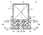
- At least a part of the lead portions 15A and 15B is pulled out from the mounting surface 13S of the mold resin layer 13 and accommodated in the groove portions 13A and 13B provided on the mounting surface 13S.
- the bottom surfaces 13a and 13b of the groove portions 13A and 13B preferably have a predetermined inclination.
- One end portions (hereinafter, also referred to as tip portions) of the rod-like portions 17A and 17B are located in the through holes provided in the sealing member 12.
- the electrolyte component tends to stay near the boundary between the sealing member 12 and the mold resin layer 13.
- the tip portions of the rod-like portions 17A and 17B are located in the through holes of the sealing member 12, the electrolyte components staying near the boundary between the sealing member 12 and the mold resin layer 13 are connected to the in-lead connecting portions 175A and 175B and the lead-out portions. It becomes easy to contact part 15A, 15B. At this time, the in-lead connecting portions 175A and 175B and the lead portions 15A and 15B are corroded by the staying electrolyte component.
- the electrolytic solution enters a wide range of the boundary between the sealing member 12 and the mold resin layer 13, and the electrolytic solution is connected between the in-lead connecting portions 175A and 175B and / or between the lead portions 15A and 15B of the pair of leads 14A and 14B. If the component stays, corrosion of the lead connecting portions 175A and 175B and / or the lead portions 15A and 15B (particularly the anode lead side) is promoted when a voltage is applied between the leads. Furthermore, as shown in FIG.
- An electrolytic capacitor includes a capacitor element including a pair of electrodes, an electrolytic solution interposed between the pair of electrodes, a case containing the capacitor element and the electrolytic solution, a sealing member, and a sealing member
- a pair of leads penetrating the member and a mold resin layer are provided.
- the sealing member seals the opening of the case.
- the pair of leads are electrically connected to the pair of electrodes, respectively.
- the mold resin layer covers at least a part of the outer surface of the sealing member.
- At least one of the pair of leads has a tab portion and a lead portion. The tab portion is connected to the electrode.
- the drawer portion is connected to the tip portion of the tab portion.
- the tip part of the tab part protrudes from the outer surface of the sealing member. Therefore, it is suppressed that the electrolyte solution component which stays contacts the connection part of the front-end
- the tab portion (or the rod-like portion and the flat portion) is originally a part accommodated in the case, and is therefore formed of a material (valve action metal or the like) that is unlikely to cause corrosion due to contact with the electrolyte. .
- the connection part in-lead connection part between the tab part and the lead part and the lead part subsequent thereto include, for example, a corrosive material (transition metal such as Fe or Cu) such as CP wire or Cu wire.
- the in-lead connection portion and the subsequent lead portion are separated from the boundary between the mold resin layer and the sealing member. be able to. As a result, contact between the electrolytic solution component and the in-lead connecting portion and the lead portion is suppressed.
- the lead component When a voltage is applied while both the pair of leads are in contact with the staying electrolyte component, the lead component is electrolyzed and lead corrosion is accelerated. Therefore, if the contact between at least one of the pair of leads and the electrolytic solution component is suppressed, corrosion of the lead is suppressed. In the anode lead and the cathode lead, the corrosion of the anode lead is likely to proceed. Therefore, it is preferable that at least the end portion (or the tip end portion of the rod-like portion) of the anode lead protrudes from the outer surface of the sealing member. However, in order to increase the effect of suppressing lead corrosion, it is desirable to suppress contact between both the pair of leads and the electrolyte component.
- the in-lead connection portion may be embedded in the mold resin layer.
- an adhesive interface between the mold resin layer and the in-lead connecting portion is formed. Since the staying electrolyte component hardly enters the adhesion interface, the effect of suppressing lead corrosion is enhanced.
- the connection part in a lead has a welding trace of a tab part and a drawer
- the end of the tab portion on the drawer portion side may have an exposed portion that is not covered with the mold resin layer. Since the exposed portion does not form an adhesive interface between the mold resin layer and the lead, the electrolyte component does not creep up to the exposed portion due to capillary action. Since the exposed portion is always exposed to the outside air, the exposed portion is not easily wetted with the electrolyte component and is easily dried. Therefore, it is suppressed that a lead contacts an electrolyte solution component.
- the entire tab portion protruding from the outer surface of the sealing member may be exposed without being covered with the mold resin layer.
- a region having no mold resin layer is formed around the through hole through which the lead passes so as to surround the through hole.
- the boundary between the mold resin layer and the sealing member is not formed around the tab portion protruding from the sealing member, and the portion is exposed to the outside. Therefore, the retention of the electrolyte component around the tab portion protruding from the sealing member is further suppressed.
- the end of the tab portion on the drawer portion side may be embedded in the mold resin layer so that the entire welding trace is covered with the mold resin layer.
- a part of the drawer part that follows the end part of the tab part on the drawer part side may be embedded together in the mold resin layer.
- the tab portion is preferably covered with a metal oxide film constituting the tab portion.
- a metal oxide film constituting the tab portion.
- the corrosion by contact with a tab part and electrolyte solution component becomes difficult to occur.
- the tab portion includes a valve action metal such as aluminum
- the tab portion can be anodized to form an oxide film on the tab portion. It is sufficient to form the oxide film only on the anode lead, but an oxide film may be formed on the cathode lead.
- the drawer part is preferably a flexible linear member.
- the linear member preferably includes a core material and a plating layer covering the surface of the core material.
- the core material preferably contains, for example, Cu having excellent conductivity, steel, Fe, or the like as a main component.
- the plating layer is preferably formed of a low melting point metal. Since the lead portion includes the low melting point metal plating layer, it becomes easy to connect the lead portion to a predetermined connected electrode. Specifically, a CP line, a Cu line, or the like can be used for the lead portion.
- the CP wire is a linear member in which a core material is formed of steel or Fe and a plating layer is formed of Sn, Cu, or the like.
- the Cu wire is a linear member in which a core material is formed of Cu and a plating layer is formed of Sn or the like.
- the transition metal When a transition metal is contained in the lead portion, the transition metal is likely to elute into the electrolyte component from the lead portion. In contrast, by causing the end of the tab portion on the drawer portion side to protrude from the outer surface of the sealing member, corrosion of the drawer portion is significantly suppressed.
- the mold resin layer only needs to cover at least a part of the outer surface of the sealing member.
- an area having no mold resin layer may be provided around the through hole for allowing the lead to pass through on the outer surface of the sealing member.
- a region other than the periphery of the through hole in the outer surface of the sealing member is covered with the mold resin layer.
- an area of 50% or more of the outer surface of the sealing member is covered with the mold resin layer.
- the entire area (100%) of the outer surface of the sealing member may be covered with the mold resin layer.
- the mold resin layer covers at least a part of the side surface following the opening of the case in addition to the outer surface of the sealing member. Thereby, the airtightness in a case can further be improved.
- the mold resin layer is preferably in close contact with the case in a region facing the case. Thereby, a mold resin layer can be fixed to a sealing member more firmly.
- An electrolytic capacitor 1A shown in FIG. 1 includes a capacitor element 10, an electrolytic solution (not shown), and a case 11 that accommodates these and has an opening.
- the case 11 is, for example, a bottomed cylindrical shape.
- the opening of the case 11 is sealed with a sealing member 12.
- the entire outer surface of the sealing member 12 facing the opening side of the case 11 is covered with the mold resin layer 13.
- the mold resin layer 13 is provided so as to cover the opening of the case 11 together with the outer surface of the sealing member 12, and further covers at least a part of the side surface following the opening of the case 11.
- the opening of the case 11 is sealed with the sealing member 12 and the mold resin layer 13 after accommodating the capacitor element 10.
- the opening end of the case 11 is drawn to the sealing member 12 side and caulked to the inside.
- the sealing member 12 is fixed to the opening of the case 11, and the case 11 is sealed by the sealing member 12.
- the mold resin layer 13 may be partially bonded to the case 11 in a region facing the case 11, and there may be an unbonded portion.
- the mold resin layer 13 preferably contains a cured product of the curable resin composition.
- the curable resin composition may contain a filler, a curing agent, a polymerization initiator, and / or a catalyst in addition to the curable resin.
- examples of the curable resin include a photocurable resin and a thermosetting resin.
- a curing agent, a polymerization initiator, a catalyst, etc. are suitably selected according to the kind of curable resin.
- the curable resin for example, a compound that is cured or polymerized by the action of heat (for example, a monomer, an oligomer, a prepolymer, or the like) is used.
- a compound (or curable resin) include epoxy resin, phenol resin, urea resin, polyimide, polyamideimide, polyurethane, diallyl phthalate, and unsaturated polyester.
- the curable resin composition may include a plurality of curable resins.
- insulating particles inorganic or organic
- insulating material constituting the filler include insulating compounds (such as oxide) such as silica and alumina, glass, mineral materials (such as talc, mica, and clay).
- the mold resin layer may contain one kind of these fillers, or may contain two or more kinds in combination.
- the content rate of the filler in a mold resin layer is 10 mass% or more and 90 mass% or less, for example.
- the mold resin layer 13 may contain a thermoplastic resin or a composition containing the same.
- a thermoplastic resin for example, polyphenylene sulfide (PPS), polybutylene terephthalate (PBT), or the like can be used.
- the mold resin layer 13 can be formed using a molding technique such as injection molding, insert molding, or compression molding.
- the mold resin layer 13 is formed in a predetermined mold in the mold so as to cover the opening of the case 11 together with the outer surface of the sealing member 12 with a curable resin composition or a thermoplastic resin (composition) using a predetermined mold, for example. It can be formed by filling a portion.
- the capacitor element 10 shown in FIG. 2 is formed by winding an anode 21 and a cathode 22 with a separator 23 interposed therebetween.
- An anode lead 14A and a cathode lead 14B are electrically connected to the anode 21 and the cathode 22, respectively. Each lead passes through the sealing member 12 and is drawn to the outside.
- the anode lead 14A and the cathode lead 14B have tab portions 16A and 16B connected to the anode 21 and the cathode 22, respectively, and lead portions 15A and 15B connected to the tab portions 16A and 16B, respectively.
- the tab portions 16A and 16B include, for example, aluminum.
- the lead portions 15A and 15B are, for example, CP wires and Cu wires containing metals such as iron, copper, nickel, and tin.
- the tab portions 16A and 16B have rod-shaped portions 17A and 17B and flat portions 18A and 18B, respectively.
- the rod-like portions 17A and 17B and the flat portions 18A and 18B may be electrically connected to each other, or may be integrated.
- a flat part is formed by rolling a part of rod-shaped body. The non-rolled region remains as a rod-shaped part. Thereby, tab part 16A, 16B with which the flat part and the rod-shaped part were integrated can be formed.
- the rod-shaped portions 17A and 17B penetrate the sealing member 12, respectively.
- the shape of the rod-like portions 17A and 17B is not particularly limited, and may be a round rod shape (for example, a rod shape having a circular or elliptical cross section) or a square bar shape (for example, a rod shape having a polygonal cross section).
- the rod-like portions 17A and 17B are connected to the capacitor element 10 via flat portions 18A and 18B, respectively. By having the flat portions 18A and 18B, it is easy to connect the leads 14A and 14B to the anode and the cathode.
- the lead portions 15A and 15B are connected to the tip portions of the rod-like portions 17A and 17B by welding or the like, and in-lead connection portions 175A and 175B are formed at the boundaries between the lead portions 15A and 15B and the rod-like portion. At least a part of each of the lead portions 15A and 15B passes through the mold resin layer 13 and is drawn to the outside.
- the shape of the lead portions 15A and 15B is not particularly limited, and may be, for example, a wire shape or a ribbon shape.
- the tip portions of the rod-like portions 17A and 17B protrude from the outer surface of the sealing member 12.
- the distance D between the in-lead connection portions 175A, 175B or the portion of the welding trace closest to the leading portion of the rod-like portions 17A, 17B and the outer surface of the sealing member 12 is the inside of the leading portions 15A, 15B or the leads. From the viewpoint of suppressing contact between the connecting portions 175A and 175B and the electrolytic solution component, it is preferably as large as possible.
- the distance D is preferably 5% or more of the maximum thickness T of the mold resin layer 13. At this time, it is desirable that the tip portions of the rod-like portions 17A and 17B do not protrude from the mounting surface 13S of the mold resin layer 13.
- the maximum thickness T of the mold resin layer 13 is the maximum value of the vertical distance between the mounting surface 13S of the mold resin layer 13 and the outer surface of the sealing member 12.
- the vertical distance refers to the distance in the normal direction of the outer surface of the sealing member
- the in-lead connecting portions 175A and 175B are embedded in the mold resin layer 13.
- the tip portions of the rod-like portions 17A and 17B are entirely covered with the mold resin layer 13, and the bonding interface between the mold resin layer 13 and the tip portions of the rod-like portions 17A and 17B is formed with a sufficiently large area. Due to such an adhesive interface, contact between the in-lead connection portions 175A and 175B or the lead portions 15A and 15B and the electrolyte component is remarkably suppressed.
- the mounting surface 13S of the mold resin layer 13 is provided with elongated grooves 13A and 13B.
- the lead portions 15A and 15B have portions drawn from the mounting surface 13S to the outside.
- the said part is arrange
- the bottom surfaces 13a and 13b are inclined so that the depth of the groove portions 13A and 13B gradually increases from the position where the lead portions 15A and 15B start to be pulled out from the mold resin layer 13 toward the outer periphery of the mounting surface 13S. Yes.
- a restoring force for returning to the original shape acts on the lead portions 15A and 15B.
- the slopes are provided on the bottom surfaces of the grooves 13A and 13B.
- the inclination angle of the bottom surfaces 13a and 13b with respect to the mounting surface 13S is, for example, 3 ° or more and 30 ° or less. Note that the depths of the grooves 13A and 13B may be constant without inclining the bottom surfaces 13a and 13b.
- the sealing member 12 may be an insulating material.
- an elastic body is preferable.
- the sealing member 12 including an elastic body such as rubber high sealing performance can be ensured. From the viewpoint of easily obtaining high heat resistance, silicone rubber, fluorine rubber, ethylene propylene rubber, chlorosulfonated polyethylene rubber (Hypalon (trademark) rubber, etc.), butyl rubber, isoprene rubber and the like are preferable.
- the sealing member 12 has a shape corresponding to the shape of the opening of the case 11 (for example, a disk shape such as a disk shape).
- the sealing member 12 has a through hole for passing the rod-like portions 17A and 17B.
- the shape and size of the through hole may be appropriately determined according to the shape and size of the rod-like portions 17A and 17B.
- the capacitor element 10 includes, for example, a wound body as shown in FIG.
- the wound body includes an anode 21 having a dielectric layer, a cathode 22, and a separator 23 interposed therebetween.
- a lead 14 ⁇ / b> A is connected to the anode 21, and a lead 14 ⁇ / b> B is connected to the cathode 22.
- FIG. 2 has shown the state by which one part was expand
- a metal foil whose surface is roughened is used.
- the kind of metal which comprises metal foil is not specifically limited, From the point that formation of a dielectric material layer is easy, it is preferable to use the alloy which contains valve action metals, such as aluminum, a tantalum, niobium, or a valve action metal.
- the roughening of the metal foil surface can be performed by a known method. By roughening, a plurality of irregularities are formed on the surface of the metal foil.
- the roughening is preferably performed, for example, by etching a metal foil.
- the etching treatment may be performed by, for example, a direct current electrolytic method or an alternating current electrolytic method.
- the dielectric layer is formed on the surface of the anode 21. Specifically, since the dielectric layer is formed on the surface of the roughened metal foil, the dielectric layer is formed along the inner wall surface of the hole or recess (pit) on the surface of the anode 21.
- the formation method of the dielectric layer is not particularly limited, but can be formed by chemical conversion treatment of the metal foil.
- the chemical conversion treatment may be performed, for example, by immersing the metal foil in a chemical conversion solution such as an ammonium adipate solution.
- a voltage may be applied in a state where the metal foil is immersed in the chemical conversion liquid as necessary.
- a metal foil is used for the cathode 22.
- the type of metal is not particularly limited, but it is preferable to use a valve action metal such as aluminum, tantalum, or niobium or an alloy containing the valve action metal.
- the cathode 22 may be subjected to surface roughening and / or chemical conversion treatment as necessary. The roughening and chemical conversion treatment can be performed by, for example, the method described for the anode 21.
- the separator 23 is not particularly limited, and for example, a nonwoven fabric containing fibers of cellulose, polyethylene terephthalate, vinylon, polyamide (for example, aromatic polyamide, aromatic polyamide such as aramid) may be used.
- the wound body can be produced by a known method.
- the leads 14A and 14B may be planted from the wound body by winding while winding the lead as shown in FIG.
- the capacitor element 10 includes an electrolytic solution.
- the electrolytic solution may be a nonaqueous solvent or a mixture of a nonaqueous solvent and an ionic substance (solute, for example, an organic salt) dissolved in the nonaqueous solvent.
- the non-aqueous solvent may be an organic solvent or an ionic liquid.
- the non-aqueous solvent for example, ethylene glycol, propylene glycol, sulfolane, ⁇ -butyrolactone, N-methylacetamide and the like can be used.
- organic salt examples include trimethylamine maleate, triethylamine borodisalicylate, triethylamine phthalate, ethyldimethylamine phthalate, mono 1,2,3,4-tetramethylimidazolinium phthalate, mono 1,3-phthalate And dimethyl-2-ethylimidazolinium.
- the capacitor element 10 may include a solid electrolyte layer that covers at least a part of the surface of the dielectric layer.
- the solid electrolyte layer includes, for example, a manganese compound and a conductive polymer.
- a conductive polymer for example, polypyrrole, polythiophene, polyaniline, and derivatives thereof can be used.
- the solid electrolyte layer can be formed, for example, by subjecting a raw material monomer to chemical polymerization and / or electrolytic polymerization on the dielectric layer.
- the dielectric layer can be formed by applying a solution in which the conductive polymer is dissolved or a dispersion liquid in which the conductive polymer is dispersed to the dielectric layer.
- a metal such as aluminum, stainless steel, copper, iron, brass, or an alloy thereof is used.
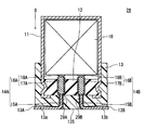
- the electrolytic capacitor 1B shown in FIG. 3 has the same structure as that of the first embodiment except that the tip portions of the rod-like portions 17A and 17B of the tab portions 16A and 16B are not embedded in the mold resin layer 13. Also in this modification, the in-lead connecting portions 175A and 175B and the subsequent lead portions 15A and 15B can be sufficiently separated from the boundary between the sealing member 12 and the mold resin layer 13.
- the mold resin layer 13 covers the entire outer surface of the sealing member 12.
- the end portions of the rod-like portions 17A and 17B and the in-lead connecting portions 175A and 175B are not embedded in the mold resin layer 13 and are exposed to the outside. Capillary phenomenon that promotes scooping up of the electrolyte component does not occur in such an exposed portion.
- the exposed portion is always exposed to the outside air and easily dried. As described above, the electrolytic solution component is further suppressed from staying between the leads.
- the distance D is preferably 5% or more of the maximum thickness T of the mold resin layer 13. At this time, it is desirable to set the distance D so that the tip portions of the rod-like portions 17A and 17B do not protrude from the mounting surface 13S of the mold resin layer 13.
- the depths of the grooves 13A and 13B are increased at the positions where the tips of the rod-shaped portions 17A and 17B protrude from the mold resin layer 13. Is preferred.
- the in-lead connection portions 175A and 175B and the subsequent lead portions 15A and 15B can be accommodated in the groove portions 13A and 13B. Therefore, it can suppress that drawer
- the electrolytic capacitor 1 ⁇ / b> C shown in FIG. 4 the entire portion of the rod-like portions 17 ⁇ / b> A and 17 ⁇ / b> B protruding from the outer surface of the sealing member 12 is exposed without being covered with the mold resin layer 13. Except this point, it has the same structure as the first embodiment.
- the distance D is preferably 5% or more of the maximum thickness T of the mold resin layer 13.
- a region that is not covered with the mold resin layer 13 is formed around the through hole of the sealing member 12 from which the rod-like portions 17A and 17B protrude, so as to surround the through hole.
- the mold resin layer 13 is formed with a cylindrical through hole into which a part of the rod-like portions 17A and 17B is inserted.
- the boundary between the mold resin layer 13 and the sealing member 12 is not formed on at least a part of the periphery of the rod-like portions 17A and 17B protruding from the sealing member 12, and the outer surface of the sealing member 12 is slightly exposed. Therefore, the boundary between the sealing member 12 and the mold resin layer 13 is discontinuous around the rod-like portions 17A and 17B protruding from the sealing member 12.
- the rod-like portions 17A and 17B protruding from the sealing member 12 do not have a capillary phenomenon that promotes the rise of the electrolyte component, and the tip portions of the rod-like portions 17A and 17B are always exposed to the outside air and dried. It becomes easy. As a result, corrosion of the lead due to the electrolyte component is further suppressed to a high degree.
- one of the anode lead and the cathode lead protrudes from the outer surface of the sealing member as shown in FIG. 1, FIG. 3, or FIG. 4, the lead is suppressed from coming into contact with the electrolyte component.
- one of the anode lead and the cathode lead has one of the configurations shown in FIG. 1, FIG. 3, or FIG. 4, and the other has any one of the other configurations shown in FIG. 1, FIG. 3, or FIG. You may have.
- An electrolytic capacitor includes a capacitor element including a pair of electrodes, an electrolytic solution interposed between the pair of electrodes, a storage case for the capacitor element and the electrolytic solution, a sealing member, and a sealing member And a pair of leads penetrating the sealing member and the mold resin layer.
- the case has an opening.
- the sealing member seals the opening of the case.
- the pair of leads are electrically connected to the pair of electrodes, respectively.
- At least one of the pair of leads has an insulating region covered with an electrically insulating layer.
- the electrical insulating layer is provided between at least one of the pair of leads and at least one of the sealing member and the mold resin layer. The electrical insulating layer only needs to be formed in at least a part of a region where the lead penetrates the sealing member and the mold resin layer.
- One of the pair of electrodes is an anode, and the other is a cathode.
- the anode has a dielectric layer on the surface.
- One of the pair of leads is an anode lead that is electrically connected to the anode, and the other is a cathode lead that is electrically connected to the cathode.
- the insulating region electrical insulating layer
- the electrolytic solution means that components (for example, a solvent or a solution in which an electrolyte salt is dissolved) contained in the electrolytic solution are retained.
- the lead may be in contact with the staying electrolytic solution not only in the region penetrating the sealing member but also in the region penetrating the mold resin layer. Therefore, if an electrical insulating layer is formed between the lead and the sealing member and / or the mold resin layer (at least in a region where the lead penetrates the sealing member and the mold resin layer), The effect of suppressing corrosion is obtained.
- the electrolytic solution tends to stay at the boundary between the sealing member and the mold resin layer
- at least one of the pair of leads should not be in contact with the boundary between the sealing member and the mold resin layer. It is preferably provided (that is, the lead does not face the boundary). In this case, the effect of providing the insulating region can be further enhanced. Furthermore, it is more preferable that the electrical insulating layer is provided across the boundary between the sealing member and the mold resin layer.
- the corrosion of the leads proceeds. To do.
- an electrically insulating layer so that at least one of the pair of leads does not contact the boundary between the sealing member and the mold resin layer, the progress of corrosion of the leads is suppressed.
- an insulating region is provided on both of the pair of leads. Further, in such a state, the anode lead easily dissolves the metal (for example, aluminum or tin) constituting the anode lead. Therefore, an insulating region may be provided only on the anode lead.
- the electrical insulating layer is preferably excellent in corrosion resistance against a solvent containing an electrolytic solution or a chlorine component. In this case, the effect of providing the insulating region can be maintained over a long period of time.
- An electrolytic capacitor 2A shown in FIG. 7 includes a capacitor element 10 including an anode foil 21 (see FIG. 2) and a cathode foil 22 (see FIG. 2), and an electrolyte solution (shown) interposed between the anode foil 21 and the cathode foil 22. And a bottomed cylindrical case 11 that accommodates the capacitor element 10 and the electrolytic solution and has an opening. Examples of the material of the case 11 include metals such as aluminum, stainless steel, copper, iron, brass, and alloys thereof.
- the electrolytic capacitor 2 ⁇ / b> A includes a sealing member 12 that seals the opening of the case 11 and a mold resin layer 13 that covers the sealing member 12.
- the mold resin layer 13 is provided so as to cover the opening of the case 11 together with the main surface disposed on the outside of the case 11 of the sealing member 12.
- the opening of case 11 is sealed with sealing member 12 and mold resin layer 13 after accommodating capacitor element 10.
- the vicinity of the opening end of the case 11 is drawn to the sealing member 12 side, and the opening end of the case 11 is crimped inward.
- the sealing member 12 is fixed to the opening of the case 11, and the case 11 is sealed by the sealing member 12.
- the mold resin layer 13 further covers at least a part of the side surface following the opening of the case 11. Thereby, the sealing performance of the electrolytic capacitor can be further enhanced.
- the mold resin layer 13, the case 11, and the sealing member 12 may have portions that are not partially bonded.
- the same configuration and materials as those of the first embodiment can be used.
- the electrolytic capacitor 2A includes a pair of leads 14A and 14B that are electrically connected to the anode foil 21 and the cathode foil 22 included in the capacitor element 10 and penetrate the sealing member 12 and the mold resin layer 13, respectively.
- leads 14A and 14B When the electrolytic capacitor is mounted on the substrate, the capacitor element 10 and the terminal on the substrate are electrically connected via the leads 14A and 14B.
- the leads 14A and 14B have tab portions 16A and 16B connected to the anode foil 21 and the cathode foil 22, respectively, and lead portions 15A and 15B connected to the tab portions 16A and 16B, respectively.
- the lead portions 15A and 15B and the tab portions 16A and 16B are connected by welding or the like.
- the lead portions 15A and 15B include a metal such as iron, copper, nickel, and tin, for example.
- the tab portions 16A and 16B include, for example, aluminum.
- the tab portions 16A and 16B have rod-like portions 17A and 17B and flat portions 18A and 18B, respectively.
- the rod-like portions 17A and 17B and the flat portions 18A and 18B may be electrically connected, or may be integrated.
- a flat part is formed by rolling one end part of a rod-like body, and a tab part in which the flat part and the rod-like part are integrated can be formed by leaving an unrolled region as a rod-like part.
- the rod-like portions 17A and 17B each include a portion disposed in the sealing member 12.
- the lead portions 15A and 15B extend from the tip portions of the rod-like portions 17A and 17B, respectively.
- the rod-like portions 17A and 17B are connected to the capacitor element 10 via flat portions 18A and 18B, respectively. By having the flat portions 18A and 18B, the connection between the leads 14A and 14B and the capacitor element is facilitated.
- the shape of the drawer portions 15A and 15B is not particularly limited, and may be, for example, a wire shape or a ribbon shape.
- the shape of the rod-shaped portions 17A and 17B is not particularly limited, and may be a round rod shape (for example, a rod shape having a circular or elliptical cross section) or a square bar shape (for example, a rod shape having a polygonal cross section). Also good.
- the leads 14A and 14B have insulating regions covered with the electrical insulating layers 19A and 19B.
- the electrically insulating layers 19A and 19B are provided between the leads 14A and 14B and the sealing member 12 and the mold resin layer 13.
- the electrical insulating layers 19A and 19B are provided, the chlorine component contained in the sealing member 12 is dissolved in the electrolytic solution staying in the sealing member 12 or at the boundary between the sealing member 12 and the mold resin layer 13. However, lead corrosion can be suppressed.
- the electrical insulating layers 19 ⁇ / b> A and 19 ⁇ / b> B are preferably provided so that the leads 14 ⁇ / b> A and 14 ⁇ / b> B do not contact the boundary between the sealing member 12 and the mold resin layer 13.
- the electrical insulating layers 19A and 19B it is possible to prevent the leads 14A and 14B from coming into contact with the electrolytic solution staying at the boundary between the sealing member 12 and the mold resin layer 13.
- the progress of corrosion of the leads 14A and 14B (particularly, the anode-side lead 14A) when a voltage is applied to the electrolytic capacitor in a state where the leads 14A and 14B are in contact with the electrolytic solution can be suppressed.
- the electrical insulating layers 19 ⁇ / b> A and 19 ⁇ / b> B are provided across the boundary between the sealing member 12 and the mold resin layer 13. In this case, it is possible to further enhance the effect of suppressing the leads 14A and 14B from coming into contact with the electrolytic solution staying at the boundary between the sealing member 12 and the mold resin layer 13.
- the electrical insulating layers 19A and 19B have excellent corrosion resistance against an electrolyte or a solvent containing a chlorine component. In this case, the effect of providing the insulating region can be maintained over a long period of time.
- the thickness of the electrical insulating layers 19A and 19B is, for example, not less than 0.01 mm and not more than 1.00 mm.
- the lead portions 15A and 15B include a transition metal
- the end portions of the lead portions 15A and 15B and the rod-like portions 17A and 17B are melted when the lead portions 15A and 15B are welded to the rod-like portions 17A and 17B.
- the transition metal is exposed on the surface of the joint. Therefore, when the joining portion comes into contact with the electrolytic solution staying at the boundary between the sealing member 12 and the mold resin layer 13, corrosion easily proceeds at the joining portion (particularly, the joining portion on the anode side), and the lead is easily disconnected at the joining portion. . Therefore, as shown in FIG.
- the joint portions between the tab portions 16A and 16B (rod-like portions 17A and 17B) and the lead portions 15A and 15B are covered with the electrical insulating layers 19A and 19B.
- the insulating region is preferably provided in a region extending from the rod-like portions 17A and 17B of the leads 14A and 14B to the lead portions 15A and 15B.
- At least a part of the joint portion between the tab portions 16 ⁇ / b> A and 16 ⁇ / b> B (rod-like portions 17 ⁇ / b> A and 17 ⁇ / b> B) and the lead portions 15 ⁇ / b> A and 15 ⁇ / b> B is formed between the sealing member 12 and the mold resin layer 13.
- the distances t 1a and t 1b in which the insulating regions extend from the boundary between the sealing member 12 and the mold resin layer 13 toward the mold resin layer 13 are preferably 10% or more of the thickness T 1 of the mold resin layer 13. . In this case, the sealing performance of the electrolytic capacitor can be further improved.
- the distances t 1a and t 1b between the insulating regions are such that the electrically insulating layers 19A and 19B are molded resin from the boundary surface between the sealing member 12 and the mold resin layer 13 along the direction perpendicular to the boundary surface. This is the distance extending to the layer 13 side.
- the thickness T 1 of the mold resin layer 13 is the thickness in the axial direction of the case 11 (X direction in FIG. 1), and the thickness of the region where the groove portions 13A and 13B of the mold resin layer 13 described later are not provided. It is.
- the distances t 2a and t 2b in which the insulating regions extend from the boundary between the sealing member 12 and the mold resin layer 13 toward the sealing member 12 are 10% or more of the thickness T 2 of the sealing member 12. In this case, the sealing performance of the electrolytic capacitor can be further improved.
- the distances t 2a and t 2b between the insulating regions are such that the electrically insulating layers 19A and 19B are sealed along the direction perpendicular to the boundary surface from the boundary surface between the sealing member 12 and the mold resin layer 13. This is the distance extending to the 12 side.
- the thickness T 2 of the sealing member 12 is the thickness in the axial direction of the case 11 (X direction in FIG. 1).
- the insulating region is provided in both the lead 14A and the lead 14B, but an insulating region may be provided in one of the lead 14A and the lead 14B.
- the electrical insulation layers 19A and 19B shown in FIG. 7 are provided, but the electrical insulation layers 29A and 29B shown in FIG. 8 may be provided.
- the electrical insulating layers 29A and 29B By providing the electrical insulating layers 29A and 29B, the contact with the electrolytic solution can be suppressed over the entire region where the leads 14A and 14B penetrate the sealing member 12 and the mold resin layer 13.
- One end of the electrical insulating layers 29A and 29B is exposed from the main surface of the sealing member 12 opposite to the mold resin layer 13 side. In this case, the effect of providing the insulating region can be further enhanced.
- the other end portions of the electrical insulating layers 29A and 29B are exposed from the mounting surface 13S side of the mold resin layer 13. In this case, the effect of providing the insulating region can be further enhanced. However, it is preferable not to provide the electrical insulating layers 29A and 29B in the portion where the leads 14A and 14B are mounted in order to improve mountability.
- the electrical insulating layers 19A, 19B, 29A, and 29B include at least one of an insulating resin layer and an insulating ceramic layer.
- an electrical insulation layer having excellent electrical insulation and corrosion resistance against an electrolytic solution a solvent containing a chlorine component
- the insulating resin layer preferably includes a cured product of a curable resin composition, a thermoplastic resin, or a composition containing the same.
- curable resin what was illustrated as a material which can be used for mold resin layers, such as thermosetting resin, for example can be used.
- the curable resin composition may contain a filler, a curing agent and the like in addition to the curable resin.
- thermosetting resin for example, phenol resin, epoxy resin, melamine resin, urea resin, unsaturated polyester, alkyd resin, polyurethane, thermosetting polyimide and the like can be used.
- the thermosetting resin is preferably a phenol resin, an epoxy resin, or a thermosetting polyimide.
- thermoplastic resin examples include fluorine resin (for example, polytetrafluoroethylene), polyamideimide, polyimide, polyethylene, polypropylene, polyvinyl chloride, polyvinylidene chloride, polystyrene, polyvinyl acetate, ABS resin, AS resin, acrylic resin, and the like. Can be used. Among them, the thermoplastic resin is preferably a fluororesin, polyamideimide, or polyimide.
- the insulating resin layer may be formed by applying a thermosetting resin composition to a predetermined portion of the lead and then curing it, or by applying a thermoplastic resin (composition) to a predetermined portion of the lead. May be.
- the insulating resin layer may be formed by sticking an insulating resin tape to a predetermined portion of the lead.
- the insulating ceramic layer preferably contains silica, metal oxide, carbide, boride, and coupling agent.
- the silica include natural crystalline silica, natural amorphous silica, synthetic crystalline silica, and synthetic amorphous silica.
- a silica contains a synthetic amorphous silica.
- the metal oxide include an oxide containing aluminum, an oxide containing titanium, and an oxide containing tantalum.
- the carbide includes, for example, silicon carbide, titanium carbide, boron carbide and the like.
- borides include aluminum diboride and titanium diboride.
- the coupling agent includes, for example, a silane coupling agent and a titanate coupling agent.
- the insulating ceramic layer is formed, for example, by attaching ceramics to a predetermined portion of the lead by an aerosol deposition method, applying a tape containing ceramics, or applying a paint containing ceramics.
- the electrical insulating layer may be formed before the lead is inserted into the sealing member, or after the lead is inserted into the sealing member.
- FIG. 9 and FIG. 10 show examples of the electrolytic capacitor when the electrical insulating layer is formed before the lead is inserted into the sealing member.
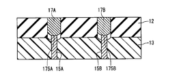
- 9 and 10 are cross-sectional views of the main part showing the vicinity of the boundary between the sealing member and the mold resin layer in the electrolytic capacitor.
- electrically insulating layers 39A and 39B shown in FIG. 9 are provided. Thereafter, the rod-like portions 17A and 17B are inserted into the sealing member 12 so that the joint portions of the lead portions 15A and 15B and the rod-like portions 17A and 17B are located in the holes of the sealing member 12, and then the mold resin layer 13 is formed. To do.
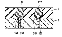
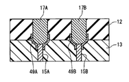
- electrically insulating layers 49A and 49B shown in FIG. 10 are provided. Thereafter, the rod-like portions 17A and 17B are inserted into the sealing member 12 so that the joint portions of the lead portions 15A and 15B and the rod-like portions 17A and 17B are located outside the hole of the sealing member 12, and then the mold resin layer 13 is formed. To do.
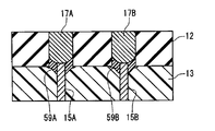
- 11 and 12 show examples of electrolytic capacitors when the electrical insulating layer is formed after the lead is inserted into the sealing member.
- 11 and 12 are cross-sectional views of the main part showing the vicinity of the boundary between the sealing member and the mold resin layer in the electrolytic capacitor.
- the rod-like portions 17A and 17B are inserted into the sealing member 12 so that the joint portions of the lead portions 15A and 15B and the rod-like portions 17A and 17B are positioned in the hole of the sealing member 12. . Thereafter, electrical insulating layers 59A and 59B shown in FIG. 11 are provided, and then a mold resin layer 13 is formed.
- the rod-shaped portions 17A and 17B are inserted into the sealing member 12 so that the joint portions of the lead portions 15A and 15B and the rod-shaped portions 17A and 17B are located outside the hole of the sealing member 12. . Thereafter, electrical insulating layers 69A and 69B shown in FIG. 12 are provided, and then a mold resin layer 13 is formed.
- the electrical insulating layer is not limited to the electrical insulating layer shown in FIGS.
- the electrical insulating layer may be provided between the lead and the sealing member and the mold resin layer (for example, straddling the boundary between the sealing member and the mold resin layer).
- the electrical insulating layer may be provided only between the lead and the sealing member (region where the lead penetrates the sealing member), or between the lead and the mold resin layer (region where the lead penetrates the mold resin). You may provide only.
- the lead portions 15 ⁇ / b> A and 15 ⁇ / b> B have a portion that is drawn out from the mounting surface 13 ⁇ / b> S side of the mold resin layer 13, and the portion is arranged along the mounting surface 13 ⁇ / b> S of the mold resin layer 13.
- elongated grooves 13A and 13B for accommodating portions (leading portions 15A and 15B) drawn out from the molding resin layer 13 of the leads 14A and 14B are formed on the mounting surface 13S of the molding resin layer 13. It may be provided.
- the lead portions 15A and 15B can be stably fixed and arranged near the mounting surface 13S.
- the bottom surfaces 13a and 13b of the groove portions 13A and 13B are formed so that the lead portions 14A and 14B of the groove portions 13A and 13B are gradually extended from one end portion of the groove portions 13A and 13B to the other end portion. Inclined to increase depth.
- the drawer portions 15A and 15B are bent so as to be substantially parallel to the mounting surface 13S, a force is applied to the drawer portions 15A and 15B to return to the original shape.
- the bottom surfaces of the groove portions 13A and 13B are inclined as described above, so that the lead portions 15A and 15B do not excessively jump out of the mounting surface 13S, and the lead portions 15A and 15B are placed in the groove portions 13A and 13B. Can be accommodated.
- the inclination angle of the bottom surfaces of the groove portions 13A and 13B with respect to the mounting surface 13S is, for example, 3 ° or more and 30 ° or less.
- the bottom surfaces of the groove portions 13A and 13B are inclined, but the depths of the groove portions 13A and 13B may be constant without inclining the bottom surfaces of the groove portions 13A and 13B.
- sealing member 12 As the sealing member 12, the same configuration and materials as those of the first embodiment can be used.
- the capacitor element 10 is the same as that of the first embodiment, the description thereof is omitted.
- the conductivity of the electrolytic solution may be low.
- the electrolyte contained in the case may contain a solvent that can dissolve the chlorine component contained in the sealing member. Therefore, even when the amount of the electrolytic solution (solvent) in the case is small, the lead may be corroded. By providing the electrically insulating layer, the effect of suppressing such corrosion of the lead can be obtained.
- the mold resin layer is usually formed in close contact with the sealing member.
- the degree of expansion (linear expansion coefficient) when the temperature rises greatly differs between the mold resin layer and the sealing member. Therefore, stress concentrates in the vicinity of the boundary between the mold resin layer and the sealing member, thereby causing cracks in the mold resin layer and reducing the sealing performance of the electrolytic capacitor.
- An electrolytic capacitor according to a third embodiment of the present disclosure includes a capacitor element that includes a pair of electrodes, a case that houses the capacitor element, a sealing member, a mold resin layer that covers the sealing member, a sealing member, and a mold resin layer.
- the case has an opening.
- the sealing member seals the opening of the case.
- the pair of leads are electrically connected to the pair of electrodes, respectively.
- a gap is provided between the sealing member and the mold resin layer.
- the gap is preferably a minute gap formed when the mold resin layer is not in close contact (adhesion) with the sealing member.
- the small gap is advantageous for miniaturization of the electrolytic capacitor.
- the minute gap can be formed by a method described later.
- the mold resin layer further covers at least a part of the side surface following the opening of the case.
- the sealing performance of the electrolytic capacitor can be further improved.
- the mold resin layer is preferably in close contact with the case in a region facing the case. In this case, the mold resin layer covering the sealing member can be more firmly fixed and provided.
- the electrolytic capacitor has an electrolytic solution
- a film of a component contained in the electrolytic solution is formed on the surface (exposed surface) of the sealing member exposed in the gap. That is, it is preferable that at least a part of the exposed surface is covered with a film of a component contained in the electrolytic solution.
- the film of the component contained in the electrolytic solution is the electrolytic solution accommodated in the case.
- These components may permeate through the sealing member and stay in the gap between the sealing member and the mold resin layer.
- a component for example, a solvent contained in the electrolytic solution is relatively easily transmitted through the sealing member. However, it is difficult to penetrate the mold resin layer.
- the component of the electrolyte that has permeated through the sealing member easily stays in the gap between the sealing member and the mold resin layer. Therefore, a film of the component of the electrolytic solution can be efficiently formed on the exposed surface of the sealing member.
- One of the pair of electrodes is an anode, and the other is a cathode.
- the anode has a dielectric layer on the surface.
- One of the pair of leads is an anode lead that is electrically connected to the anode, and the other is a cathode lead that is electrically connected to the cathode.
- a pair of leads penetrating the sealing member and the mold resin layer is exposed in a gap provided between the sealing member and the mold resin layer. Therefore, it is preferable that at least one of the pair of leads has an insulating region covered with an electrical insulating layer. More preferably, the insulating region is provided across at least the gap. That is, it is more preferable that the insulating region is provided so that the lead passes through the gap from the portion that penetrates the sealing member to the portion that penetrates the mold resin layer.
- the insulating region By providing the insulating region, even when a film of the component contained in the electrolytic solution is formed in the gap between the sealing member and the mold resin layer (the component contained in the electrolytic solution stays), a pair of leads, Contact with the components of the electrolytic solution is suppressed. If a voltage is applied to the electrolytic capacitor in a state where the pair of leads and the components of the electrolytic solution are in contact with each other, corrosion of the leads (particularly, the anode lead) proceeds. Providing the insulating region suppresses the progress of such corrosion.
- both the pair of leads are provided with insulating regions.
- the electrical insulating layer is preferably excellent in resistance to electrolyte. In this case, the effect of providing the insulating region can be maintained over a long period of time.
- the electrical insulating layer preferably includes, for example, at least one of an insulating resin layer and an insulating ceramic layer.
- the electrolytic capacitor may include an electrolytic solution interposed between the pair of electrodes, and the electrolytic solution may be accommodated in the case.
- the electrolytic capacitor may include a solid electrolyte layer that covers at least a part of the surface of the dielectric layer.
- the electrolytic capacitor may include both the electrolytic solution and the solid electrolyte layer.
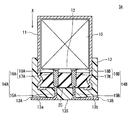
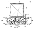
- An electrolytic capacitor 3A shown in FIG. 13 includes a capacitor element 10 including an anode foil 21 (see FIG. 2) and a cathode foil 22 (see FIG. 2), and an electrolyte solution (shown) interposed between the anode foil 21 and the cathode foil 22. And a bottomed cylindrical case 11 that accommodates the capacitor element 10 and the electrolytic solution and has an opening. Examples of the material of the case 11 include metals such as aluminum, stainless steel, copper, iron, brass, and alloys thereof.
- the electrolytic capacitor 3 ⁇ / b> A includes a sealing member 12 that seals the opening of the case 11 and a mold resin layer 13 that covers the sealing member 12.
- the mold resin layer 13 is provided so as to cover the opening of the case 11 together with the main surface disposed on the outside of the case 11 of the sealing member 12.
- the opening of case 11 is sealed with sealing member 12 and mold resin layer 13 after accommodating capacitor element 10.
- the vicinity of the opening end of the case 11 is drawn to the sealing member 12 side, and the opening end of the case 11 is crimped inward. Thereby, the sealing member 12 is fixed to the opening of the case 11, and the case 11 is sealed by the sealing member 12.
- the sealing performance of the electrolytic capacitor 3A is further enhanced.
- the mold resin layer 13 is not bonded to the sealing member 12 in a region facing the sealing member 12, and a minute gap 20 is formed between the mold resin layer 13 and the sealing member 12.
- a minute gap 20 is formed between the mold resin layer 13 and the sealing member 12.
- the mold resin layer 13 further covers at least a part of the side surface following the opening of the case 11. Thereby, the sealing performance of the electrolytic capacitor 3A can be further improved.
- the mold resin layer 13 is bonded to the case 11 in a region facing the case 11. Thereby, the mold resin layer 13 covering the sealing member 12 can be firmly fixed and provided.
- the mold resin layer 13 only needs to be partially bonded to the case 11 in a region facing the case 11, and there may be a portion that is not bonded.
- the same configuration and materials as those of the first embodiment can be used.
- a predetermined region of the sealing member 12 region covered with the mold resin layer 13.
- a release agent may be applied.
- the release agent for example, a silicone-based or fluorine-based release agent is used.
- a film (not shown) of a component contained in the electrolytic solution is formed on the surface (exposed surface) of the sealing member 12 exposed in the gap 20.
- the component of the electrolyte contained in the electrolytic solution may be formed so as to cover at least a part of the exposed surface of the sealing member 12 by retaining the component of the electrolytic solution that has passed through the sealing member 12 in the gap 20. it can.
- the electrolytic capacitor includes a pair of leads 14A and 14B that are electrically connected to the anode foil 21 and the cathode foil 22 included in the capacitor element 10 and penetrate the sealing member 12 and the mold resin layer 13, respectively.
- leads 14A and 14B When the electrolytic capacitor is mounted on the substrate, the capacitor element 10 and the terminal on the substrate are electrically connected via the leads 14A and 14B.
- the leads 14A and 14B have tab portions 16A and 16B connected to the anode foil 21 and the cathode foil 22, respectively, and lead portions 15A and 15B connected to the tab portions 16A and 16B, respectively.
- the lead portions 15A and 15B and the tab portions 16A and 16B are connected by welding or the like.
- the lead portions 15A and 15B include a metal such as iron, copper, nickel, and tin, for example.
- the tab portions 16A and 16B include, for example, aluminum.
- the tab portions 16A and 16B have rod-like portions 17A and 17B and flat portions 18A and 18B, respectively.
- the rod-like portions 17A and 17B and the flat portions 18A and 18B may be electrically connected, or may be integrated.
- a flat part is formed by rolling one end part of a rod-like body, and a tab part in which the flat part and the rod-like part are integrated can be formed by leaving an unrolled region as a rod-like part.
- the rod-shaped portions 17A and 17B each include a portion that penetrates the sealing member 12.
- the shape of the rod-shaped portions 17A and 17B is not particularly limited, and may be a round rod shape (for example, a rod shape having a circular or elliptical cross section) or a square bar shape (for example, a rod shape having a polygonal cross section). Also good.
- the rod-like portions 17A and 17B are connected to the capacitor element 10 via flat portions 18A and 18B, respectively. By having the flat portions 18A and 18B, the connection between the leads 14A and 14B and the capacitor element is facilitated.
- the lead portions 15A and 15B each include a portion penetrating the mold resin layer 13.
- the shape of the lead portions 15A and 15B is not particularly limited, and may be, for example, a wire shape or a ribbon shape.
- the lead portions 15A and 15B extend from the tip portions of the rod-like portions 17A and 17B, respectively.
- FIG. 14 is a cross-sectional view of the main part showing the vicinity of the boundary between the sealing member and the mold resin layer in the electrolytic capacitor.
- the rod-like portions 17A and 17B are inserted into the holes of the sealing member 12 so that the joint portions of the lead portions 15A and 15B and the rod-like portions 17A and 17B are positioned in the holes of the sealing member 12. .
- the tip portions of the rod-like portions 17A and 17B are exposed from the sealing member 12 on the mold resin layer 13 side.
- a gap 30 is provided between the end portions of the rod-like portions 17 ⁇ / b> A and 17 ⁇ / b> B and the sealing member 12 and the mold resin layer 13.
- the gap 30 is formed by the following method, for example.
- the rod-like portions 17A and 17B are inserted into the holes of the sealing member 12 so that the joint portions of the lead portions 15A and 15B and the rod-like portions 17A and 17B are located in the holes of the sealing member 12. Thereafter, when the mold resin layer 13 is formed, a release agent is applied to the tip portions of the rod-like portions 17A and 17B and a predetermined region of the sealing member 12 (region covered with the mold resin layer 13).
- FIG. 15 shows an example of an electrolytic capacitor in the case where a gap is formed in a state where the rod-like portion is inserted into the hole of the sealing member so that the joint portion between the drawer portion and the rod-like portion is located outside the hole of the sealing member. Shown in FIG. 15 is a cross-sectional view of the main part showing the vicinity of the boundary between the sealing member and the mold resin layer in the electrolytic capacitor.
- the rod-like portions 17 ⁇ / b> A and 17 ⁇ / b> B are inserted into the holes of the sealing member 12 so that the joint portions of the drawer portions 15 ⁇ / b> A and 15 ⁇ / b> B and the rod-like portions 17 ⁇ / b> A and 17 ⁇ / b> B are located outside the hole of the sealing member 12. .
- the tip portions of the rod-like portions 17A and 17B are exposed from the sealing member 12 on the mold resin layer 13 side.
- a gap 40 is provided between the end portions of the rod-like portions 17 ⁇ / b> A and 17 ⁇ / b> B and the sealing member 12 and the mold resin layer 13.
- the gap 40 is formed by the following method, for example.
- the rod-like portions 17A and 17B are inserted into the holes of the sealing member 12 so that the joint portions of the lead portions 15A and 15B and the rod-like portions 17A and 17B are located in the holes of the sealing member 12. Thereafter, when the mold resin layer 13 is formed, a release agent is applied to the tip portions of the rod-like portions 17A and 17B and a predetermined region of the sealing member 12 (region covered with the mold resin layer 13).
- the rod-like portions 17A and 17B are disposed between the tip portions of the rod-like portions 17A and 17B and the mold resin layer 13.
- a gap that is continuous with the gap formed between the sealing member 12 and the mold resin layer 13 may be further formed.
- the leads 14A and 14B have insulating regions covered with the electrical insulating layers 19A and 19B.
- the insulating region is preferably provided across at least the gap 20. That is, it is preferable that the insulating region is provided so that the leads 14A and 14B pass through the gap 20 from the portion that penetrates the sealing member 12 to the portion that penetrates the mold resin layer 13.
- an insulating region is provided in both the lead 14A and the lead 14B, but an insulating region may be provided in one of the lead 14A and the lead 14B.
- the lead portions 15A and 15B include a transition metal
- the end portions of the lead portions 15A and 15B and the rod-like portions 17A and 17B are melted when the lead portions 15A and 15B are welded to the rod-like portions 17A and 17B.
- the transition metal is exposed on the surface of the joint. Therefore, when the joint portion comes into contact with the component of the electrolytic solution staying in the gap 20, corrosion tends to proceed at the joint portion (particularly, the joint portion on the anode side), and the lead is easily broken at the joint portion. Therefore, as shown in FIG.
- the joint portions between the tab portions 16A and 16B (rod-like portions 17A and 17B) and the lead portions 15A and 15B are covered with the electrical insulating layers 19A and 19B.
- the insulating region is preferably provided in a region extending from the rod-like portions 17A and 17B of the leads 14A and 14B to the lead portions 15A and 15B.
- the distances t 1a and t 1b in which the insulating regions extend from the boundary between the mold resin layer 13 and the gap 20 to the mold resin layer 13 side are preferably 10% or more of the thickness T 1 of the mold resin layer 13. In this case, the effect of providing the insulating region can be further enhanced.
- the distances t 1a and t 1b between the insulating regions are such that the electrically insulating layers 19A and 19B are molded resin layers along the direction perpendicular to the boundary surface from the boundary surface between the mold resin layer 13 and the gap 20. This is the distance extending to the 13th side.
- the thickness T 1 of the mold resin layer 13 is the thickness of the case 11 in the axial direction (X direction in FIG. 16), and the thickness of the region where the groove portions 13A and 13B of the mold resin layer 13 to be described later are not provided. It is.
- the distances t 2a and t 2b in which the insulating region extends from the boundary between the sealing member 12 and the gap 20 to the sealing member 12 side is preferably 10% or more of the thickness T 2 of the sealing member 12. In this case, the effect of providing the insulating region can be further enhanced.
- the distances t 2a and t 2b between the insulating regions are such that the electrically insulating layers 19A and 19B are on the sealing member 12 side along the direction perpendicular to the boundary surface from the boundary surface between the sealing member 12 and the gap 20. It is the distance extended to.
- the thickness T 2 of the sealing member 12 is the thickness in the axial direction of the case 11 (X direction in FIG. 16).
- the electrical insulating layers 19A and 19B include an insulating resin layer and / or an insulating ceramic layer excellent in electrolytic solution resistance.
- the thickness of the electrical insulating layers 19A and 19B may be, for example, 0.01 mm or more and 1.00 mm or less.
- the insulating resin layer and the insulating ceramic layer As the insulating resin layer and the insulating ceramic layer, the same configuration and materials as those of the second embodiment can be used.
- the insulating ceramic layer is formed, for example, by attaching ceramics to a predetermined portion of the lead by an aerosol deposition method, applying a tape containing ceramics, or applying a paint containing ceramics. .
- the lead portions 15 ⁇ / b> A and 15 ⁇ / b> B have portions drawn out from the mounting surface 13 ⁇ / b> S side of the mold resin layer 13.
- the portion is arranged along the mounting surface 13 ⁇ / b> S of the mold resin layer 13.
- elongated grooves 13A and 13B for accommodating the portions of the leads 14A and 14B drawn from the mold resin layer 13 to the outside are provided on the mounting surface 13S of the mold resin layer 13, as shown in FIG. 13, elongated grooves 13A and 13B for accommodating the portions of the leads 14A and 14B drawn from the mold resin layer 13 to the outside are provided. It may be provided.
- the lead portions 15A and 15B can be stably fixed and arranged near the mounting surface 13S.
- the bottom surfaces 13a and 13b of the groove portions 13A and 13B are formed so that the lead portions 14A and 14B of the groove portions 13A and 13B are gradually extended from one end portion of the groove portions 13A and 13B to the other end portion. Inclined to increase depth.
- a force is applied to the drawer portions 15A and 15B to return to the original shape.
- the lead portions 15A and 15B do not excessively jump out of the mounting surface 13S, and the lead portions 15A and 15B are moved to the groove portions 13A and 13B.
- the inclination angles of the bottom surfaces 13a and 13b of the groove portions 13A and 13B with respect to the mounting surface 13S are, for example, 3 ° or more and 30 ° or less.
- the bottom surfaces of the groove portions 13A and 13B are inclined, but the depths of the groove portions 13A and 13B may be constant without inclining the bottom surfaces of the groove portions 13A and 13B.
- sealing member 12 As the sealing member 12, the same configuration and materials as those of the first embodiment can be used.
- Capacitor element 10 may include an electrolytic solution and a solid electrolyte layer.
- the present disclosure is useful in an electrolytic capacitor including an electrolytic solution in a case and including a sealing member and a mold resin layer.
- Electrolytic capacitor 10 Capacitor element 11: Case 12: Sealing member 13: Mold resin layer 13S: Mounting surface 13A, 13B: Groove 13a, 13b: Bottom surface 14A, 14B: Lead 15A, 15B: Drawer portion 16A, 16B: Tab portion 17A, 17B: Rod-like portion 18A, 18B: Flat portion 19A, 19B, 29A, 29B, 39A, 39B, 49A, 49B, 59A, 59B, 69A, 69B : Electrical insulating layers 20, 30, 40: Crevice 21: Anode, anode foil 22: Cathode, cathode foil 23: Separator 24: Winding tape 175A, 175B: In-lead connection portion
Landscapes
- Engineering & Computer Science (AREA)
- Power Engineering (AREA)
- Microelectronics & Electronic Packaging (AREA)
- Electric Double-Layer Capacitors Or The Like (AREA)
- Fixed Capacitors And Capacitor Manufacturing Machines (AREA)
Priority Applications (3)
| Application Number | Priority Date | Filing Date | Title |
|---|---|---|---|
| JP2018547591A JP7122514B2 (ja) | 2016-10-31 | 2017-10-18 | 電解コンデンサ |
| JP2022112831A JP7340803B2 (ja) | 2016-10-31 | 2022-07-14 | 電解コンデンサ |
| JP2023133060A JP7611537B2 (ja) | 2016-10-31 | 2023-08-17 | 電解コンデンサ |
Applications Claiming Priority (6)
| Application Number | Priority Date | Filing Date | Title |
|---|---|---|---|
| JP2016213725 | 2016-10-31 | ||
| JP2016-213724 | 2016-10-31 | ||
| JP2016-213725 | 2016-10-31 | ||
| JP2016213724 | 2016-10-31 | ||
| JP2016-233480 | 2016-11-30 | ||
| JP2016233480 | 2016-11-30 |
Publications (1)
| Publication Number | Publication Date |
|---|---|
| WO2018079358A1 true WO2018079358A1 (ja) | 2018-05-03 |
Family
ID=62023496
Family Applications (1)
| Application Number | Title | Priority Date | Filing Date |
|---|---|---|---|
| PCT/JP2017/037621 Ceased WO2018079358A1 (ja) | 2016-10-31 | 2017-10-18 | 電解コンデンサ |
Country Status (2)
| Country | Link |
|---|---|
| JP (3) | JP7122514B2 (https=) |
| WO (1) | WO2018079358A1 (https=) |
Cited By (2)
| Publication number | Priority date | Publication date | Assignee | Title |
|---|---|---|---|---|
| WO2021193794A1 (ja) * | 2020-03-26 | 2021-09-30 | 日本ケミコン株式会社 | コンデンサおよびその製造方法 |
| JP2022106262A (ja) * | 2021-01-06 | 2022-07-19 | 豊賓電子(深▲せん▼)有限公司 | 集積コンデンサ |
Citations (10)
| Publication number | Priority date | Publication date | Assignee | Title |
|---|---|---|---|---|
| JPS542344Y1 (https=) * | 1969-09-30 | 1979-01-31 | ||
| JPS61156226U (https=) * | 1985-03-18 | 1986-09-27 | ||
| JPH03261125A (ja) * | 1990-03-09 | 1991-11-21 | Marcon Electron Co Ltd | アルミニウム電解コンデンサ |
| JPH0727143U (ja) * | 1993-10-07 | 1995-05-19 | マルコン電子株式会社 | アルミニウム電解コンデンサ |
| JPH09115785A (ja) * | 1995-10-18 | 1997-05-02 | Nippon Chemicon Corp | 電解コンデンサ |
| JP2001284175A (ja) * | 2000-03-31 | 2001-10-12 | Nippon Chemicon Corp | 固体電解コンデンサとその製造方法 |
| JP2005183575A (ja) * | 2003-12-18 | 2005-07-07 | Matsushita Electric Ind Co Ltd | 面実装型アルミ電解コンデンサ及びその製造方法 |
| JP2007258422A (ja) * | 2006-03-23 | 2007-10-04 | Sanyo Electric Co Ltd | 固体電解コンデンサ及びその製造方法 |
| JP2011077368A (ja) * | 2009-09-30 | 2011-04-14 | Nippon Chemicon Corp | 表面実装型固体電解コンデンサ及びその製造方法 |
| JP2016096364A (ja) * | 2016-02-22 | 2016-05-26 | エルナー株式会社 | アルミニウム電解コンデンサ |
Family Cites Families (19)
| Publication number | Priority date | Publication date | Assignee | Title |
|---|---|---|---|---|
| JPS55132032A (en) * | 1979-03-31 | 1980-10-14 | Nichicon Capacitor Ltd | Electrolytic condenser |
| JPS6032346B2 (ja) * | 1980-01-21 | 1985-07-27 | 三洋電機株式会社 | 電解コンデンサの製造方法 |
| JPS60245113A (ja) * | 1984-05-18 | 1985-12-04 | 松下電器産業株式会社 | 電子部品 |
| JPS60245106A (ja) * | 1984-05-18 | 1985-12-04 | 松下電器産業株式会社 | チツプ形アルミ電解コンデンサ |
| JPS6158227A (ja) * | 1984-08-29 | 1986-03-25 | ニチコン株式会社 | チツプ形電解コンデンサ |
| JPS6159816A (ja) * | 1984-08-31 | 1986-03-27 | 日本ケミコン株式会社 | リ−ドレス型電解コンデンサ |
| JPS6146723U (ja) * | 1984-08-31 | 1986-03-28 | 日本ケミコン株式会社 | 電子部品 |
| JPS62196327U (https=) * | 1986-06-04 | 1987-12-14 | ||
| JP2673991B2 (ja) * | 1989-01-24 | 1997-11-05 | 日本ケミコン株式会社 | チップ型コンデンサおよびその製造方法 |
| JPH02129723U (https=) * | 1989-03-31 | 1990-10-25 | ||
| JPH03183112A (ja) * | 1990-11-29 | 1991-08-09 | Nippon Chemicon Corp | リードレス型電解コンデンサの製造方法 |
| JPH07201679A (ja) * | 1993-12-28 | 1995-08-04 | Matsushita Electric Ind Co Ltd | アルミ電解コンデンサ |
| JP3550232B2 (ja) * | 1995-11-06 | 2004-08-04 | ニチコン株式会社 | 電解コンデンサ用タブ端子の製造方法 |
| JP2001232722A (ja) | 2000-02-23 | 2001-08-28 | Kohoku Kogyo Kk | ゴムを基材とする複合材料及びその製造方法 |
| JP2002299190A (ja) | 2001-03-29 | 2002-10-11 | Nippon Chemicon Corp | 電解コンデンサ |
| JP2003264124A (ja) * | 2002-03-08 | 2003-09-19 | Nippon Chemicon Corp | チップ形コンデンサ |
| CN102523759B (zh) * | 2010-09-10 | 2013-08-14 | 松下电器产业株式会社 | 电子部件及电子部件用导线 |
| JP2016063186A (ja) * | 2014-09-22 | 2016-04-25 | 日本ケミコン株式会社 | 電子部品およびその製造方法 |
| CN113012930B (zh) * | 2016-09-28 | 2022-11-15 | 日本贵弥功株式会社 | 电容器及其制造方法 |
-
2017
- 2017-10-18 WO PCT/JP2017/037621 patent/WO2018079358A1/ja not_active Ceased
- 2017-10-18 JP JP2018547591A patent/JP7122514B2/ja active Active
-
2022
- 2022-07-14 JP JP2022112831A patent/JP7340803B2/ja active Active
-
2023
- 2023-08-17 JP JP2023133060A patent/JP7611537B2/ja active Active
Patent Citations (10)
| Publication number | Priority date | Publication date | Assignee | Title |
|---|---|---|---|---|
| JPS542344Y1 (https=) * | 1969-09-30 | 1979-01-31 | ||
| JPS61156226U (https=) * | 1985-03-18 | 1986-09-27 | ||
| JPH03261125A (ja) * | 1990-03-09 | 1991-11-21 | Marcon Electron Co Ltd | アルミニウム電解コンデンサ |
| JPH0727143U (ja) * | 1993-10-07 | 1995-05-19 | マルコン電子株式会社 | アルミニウム電解コンデンサ |
| JPH09115785A (ja) * | 1995-10-18 | 1997-05-02 | Nippon Chemicon Corp | 電解コンデンサ |
| JP2001284175A (ja) * | 2000-03-31 | 2001-10-12 | Nippon Chemicon Corp | 固体電解コンデンサとその製造方法 |
| JP2005183575A (ja) * | 2003-12-18 | 2005-07-07 | Matsushita Electric Ind Co Ltd | 面実装型アルミ電解コンデンサ及びその製造方法 |
| JP2007258422A (ja) * | 2006-03-23 | 2007-10-04 | Sanyo Electric Co Ltd | 固体電解コンデンサ及びその製造方法 |
| JP2011077368A (ja) * | 2009-09-30 | 2011-04-14 | Nippon Chemicon Corp | 表面実装型固体電解コンデンサ及びその製造方法 |
| JP2016096364A (ja) * | 2016-02-22 | 2016-05-26 | エルナー株式会社 | アルミニウム電解コンデンサ |
Cited By (8)
| Publication number | Priority date | Publication date | Assignee | Title |
|---|---|---|---|---|
| WO2021193794A1 (ja) * | 2020-03-26 | 2021-09-30 | 日本ケミコン株式会社 | コンデンサおよびその製造方法 |
| CN115298781A (zh) * | 2020-03-26 | 2022-11-04 | 日本贵弥功株式会社 | 电容器及其制造方法 |
| JP7494516B2 (ja) | 2020-03-26 | 2024-06-04 | 日本ケミコン株式会社 | コンデンサおよびその製造方法 |
| CN115298781B (zh) * | 2020-03-26 | 2025-02-25 | 日本贵弥功株式会社 | 电容器及其制造方法 |
| US12237116B2 (en) | 2020-03-26 | 2025-02-25 | Nippon Chemi-Con Corporation | Capacitor and method for manufacturing same |
| TWI895389B (zh) * | 2020-03-26 | 2025-09-01 | 日商日本貴彌功股份有限公司 | 電容器及其製造方法 |
| JP2022106262A (ja) * | 2021-01-06 | 2022-07-19 | 豊賓電子(深▲せん▼)有限公司 | 集積コンデンサ |
| JP7175451B2 (ja) | 2021-01-06 | 2022-11-21 | 豊賓電子科技股▲フン▼有限公司 | 集積コンデンサ |
Also Published As
| Publication number | Publication date |
|---|---|
| JP7611537B2 (ja) | 2025-01-10 |
| JP2022141786A (ja) | 2022-09-29 |
| JP7340803B2 (ja) | 2023-09-08 |
| JP7122514B2 (ja) | 2022-08-22 |
| JP2023156462A (ja) | 2023-10-24 |
| JPWO2018079358A1 (ja) | 2019-09-12 |
Similar Documents
| Publication | Publication Date | Title |
|---|---|---|
| US12062502B2 (en) | Electrolytic capacitor and manufacturing method thereof | |
| JP7706069B2 (ja) | 電解コンデンサおよびその製造方法 | |
| JPWO2018020993A1 (ja) | 電解コンデンサ | |
| JP2015142134A (ja) | 固体電解コンデンサ | |
| US8169774B2 (en) | Solid electrolytic capacitor and a method for manufacturing same | |
| JP7611537B2 (ja) | 電解コンデンサ | |
| CN108701547A (zh) | 固体电解电容器及其制造方法 | |
| JP2009182157A (ja) | 固体電解コンデンサ | |
| JP7426591B2 (ja) | 電解コンデンサモジュール | |
| JPWO2018123525A1 (ja) | 電解コンデンサ | |
| CN111048316B (zh) | 固体电解电容器及其制造方法 | |
| JP4946493B2 (ja) | フィルムコンデンサ | |
| JP7382591B2 (ja) | 電解コンデンサおよびその製造方法 | |
| US12027322B2 (en) | Electrolytic capacitor | |
| US20120147530A1 (en) | Solid electrolytic capacitor and method for manufacturing the same | |
| JP2010087241A (ja) | 固体電解コンデンサ | |
| KR101741573B1 (ko) | 커패시터 및 그 제조 방법 | |
| JP4710651B2 (ja) | 電気二重層キャパシタ | |
| JP2019145696A (ja) | 電解コンデンサ | |
| JP2004247418A (ja) | 電解コンデンサ | |
| CN101385103A (zh) | 双电层电容器 | |
| JP2010153690A (ja) | 固体電解コンデンサ及びその製造方法 |
Legal Events
| Date | Code | Title | Description |
|---|---|---|---|
| 121 | Ep: the epo has been informed by wipo that ep was designated in this application |
Ref document number: 17864690 Country of ref document: EP Kind code of ref document: A1 |
|
| ENP | Entry into the national phase |
Ref document number: 2018547591 Country of ref document: JP Kind code of ref document: A |
|
| NENP | Non-entry into the national phase |
Ref country code: DE |
|
| 122 | Ep: pct application non-entry in european phase |
Ref document number: 17864690 Country of ref document: EP Kind code of ref document: A1 |