WO2018078754A1 - 画像形成装置 - Google Patents
画像形成装置 Download PDFInfo
- Publication number
- WO2018078754A1 WO2018078754A1 PCT/JP2016/081794 JP2016081794W WO2018078754A1 WO 2018078754 A1 WO2018078754 A1 WO 2018078754A1 JP 2016081794 W JP2016081794 W JP 2016081794W WO 2018078754 A1 WO2018078754 A1 WO 2018078754A1
- Authority
- WO
- WIPO (PCT)
- Prior art keywords
- image
- document
- recording paper
- unit
- image processing
- Prior art date
- Legal status (The legal status is an assumption and is not a legal conclusion. Google has not performed a legal analysis and makes no representation as to the accuracy of the status listed.)
- Ceased
Links
Images


Classifications
-
- H—ELECTRICITY
- H04—ELECTRIC COMMUNICATION TECHNIQUE
- H04N—PICTORIAL COMMUNICATION, e.g. TELEVISION
- H04N1/00—Scanning, transmission or reproduction of documents or the like, e.g. facsimile transmission; Details thereof
- H04N1/23—Reproducing arrangements
- H04N1/2307—Circuits or arrangements for the control thereof, e.g. using a programmed control device, according to a measured quantity
- H04N1/233—Circuits or arrangements for the control thereof, e.g. using a programmed control device, according to a measured quantity according to characteristics of the data to be reproduced, e.g. number of lines
-
- H—ELECTRICITY
- H04—ELECTRIC COMMUNICATION TECHNIQUE
- H04N—PICTORIAL COMMUNICATION, e.g. TELEVISION
- H04N1/00—Scanning, transmission or reproduction of documents or the like, e.g. facsimile transmission; Details thereof
- H04N1/387—Composing, repositioning or otherwise geometrically modifying originals
- H04N1/3877—Image rotation
-
- B—PERFORMING OPERATIONS; TRANSPORTING
- B41—PRINTING; LINING MACHINES; TYPEWRITERS; STAMPS
- B41J—TYPEWRITERS; SELECTIVE PRINTING MECHANISMS, i.e. MECHANISMS PRINTING OTHERWISE THAN FROM A FORME; CORRECTION OF TYPOGRAPHICAL ERRORS
- B41J21/00—Column, tabular or like printing arrangements; Means for centralising short lines
-
- B—PERFORMING OPERATIONS; TRANSPORTING
- B41—PRINTING; LINING MACHINES; TYPEWRITERS; STAMPS
- B41J—TYPEWRITERS; SELECTIVE PRINTING MECHANISMS, i.e. MECHANISMS PRINTING OTHERWISE THAN FROM A FORME; CORRECTION OF TYPOGRAPHICAL ERRORS
- B41J29/00—Details of, or accessories for, typewriters or selective printing mechanisms not otherwise provided for
- B41J29/42—Scales and indicators, e.g. for determining side margins
-
- G—PHYSICS
- G03—PHOTOGRAPHY; CINEMATOGRAPHY; ANALOGOUS TECHNIQUES USING WAVES OTHER THAN OPTICAL WAVES; ELECTROGRAPHY; HOLOGRAPHY
- G03G—ELECTROGRAPHY; ELECTROPHOTOGRAPHY; MAGNETOGRAPHY
- G03G13/00—Electrographic processes using a charge pattern
- G03G13/34—Editing, i.e. producing a composite image by copying one or more original images or parts thereof
-
- G—PHYSICS
- G03—PHOTOGRAPHY; CINEMATOGRAPHY; ANALOGOUS TECHNIQUES USING WAVES OTHER THAN OPTICAL WAVES; ELECTROGRAPHY; HOLOGRAPHY
- G03G—ELECTROGRAPHY; ELECTROPHOTOGRAPHY; MAGNETOGRAPHY
- G03G15/00—Apparatus for electrographic processes using a charge pattern
- G03G15/22—Apparatus for electrographic processes using a charge pattern involving the combination of more than one step according to groups G03G13/02 - G03G13/20
-
- G—PHYSICS
- G03—PHOTOGRAPHY; CINEMATOGRAPHY; ANALOGOUS TECHNIQUES USING WAVES OTHER THAN OPTICAL WAVES; ELECTROGRAPHY; HOLOGRAPHY
- G03G—ELECTROGRAPHY; ELECTROPHOTOGRAPHY; MAGNETOGRAPHY
- G03G15/00—Apparatus for electrographic processes using a charge pattern
- G03G15/22—Apparatus for electrographic processes using a charge pattern involving the combination of more than one step according to groups G03G13/02 - G03G13/20
- G03G15/23—Apparatus for electrographic processes using a charge pattern involving the combination of more than one step according to groups G03G13/02 - G03G13/20 specially adapted for copying both sides of an original or for copying on both sides of a recording or image-receiving material
- G03G15/231—Arrangements for copying on both sides of a recording or image-receiving material
- G03G15/232—Arrangements for copying on both sides of a recording or image-receiving material using a single reusable electrographic recording member
- G03G15/234—Arrangements for copying on both sides of a recording or image-receiving material using a single reusable electrographic recording member by inverting and refeeding the image receiving material with an image on one face to the recording member to transfer a second image on its second face, e.g. by using a duplex tray; Details of duplex trays or inverters
- G03G15/235—Arrangements for copying on both sides of a recording or image-receiving material using a single reusable electrographic recording member by inverting and refeeding the image receiving material with an image on one face to the recording member to transfer a second image on its second face, e.g. by using a duplex tray; Details of duplex trays or inverters the image receiving member being preconditioned before transferring the second image, e.g. decurled, or the second image being formed with different operating parameters, e.g. a different fixing temperature
-
- G—PHYSICS
- G03—PHOTOGRAPHY; CINEMATOGRAPHY; ANALOGOUS TECHNIQUES USING WAVES OTHER THAN OPTICAL WAVES; ELECTROGRAPHY; HOLOGRAPHY
- G03G—ELECTROGRAPHY; ELECTROPHOTOGRAPHY; MAGNETOGRAPHY
- G03G15/00—Apparatus for electrographic processes using a charge pattern
- G03G15/60—Apparatus which relate to the handling of originals
-
- H—ELECTRICITY
- H04—ELECTRIC COMMUNICATION TECHNIQUE
- H04N—PICTORIAL COMMUNICATION, e.g. TELEVISION
- H04N1/00—Scanning, transmission or reproduction of documents or the like, e.g. facsimile transmission; Details thereof
- H04N1/00002—Diagnosis, testing or measuring; Detecting, analysing or monitoring not otherwise provided for
- H04N1/00026—Methods therefor
- H04N1/00037—Detecting, i.e. determining the occurrence of a predetermined state
-
- H—ELECTRICITY
- H04—ELECTRIC COMMUNICATION TECHNIQUE
- H04N—PICTORIAL COMMUNICATION, e.g. TELEVISION
- H04N1/00—Scanning, transmission or reproduction of documents or the like, e.g. facsimile transmission; Details thereof
- H04N1/0035—User-machine interface; Control console
- H04N1/00352—Input means
-
- H—ELECTRICITY
- H04—ELECTRIC COMMUNICATION TECHNIQUE
- H04N—PICTORIAL COMMUNICATION, e.g. TELEVISION
- H04N1/00—Scanning, transmission or reproduction of documents or the like, e.g. facsimile transmission; Details thereof
- H04N1/00681—Detecting the presence, position or size of a sheet or correcting its position before scanning
- H04N1/00684—Object of the detection
- H04N1/00718—Skew
-
- H—ELECTRICITY
- H04—ELECTRIC COMMUNICATION TECHNIQUE
- H04N—PICTORIAL COMMUNICATION, e.g. TELEVISION
- H04N1/00—Scanning, transmission or reproduction of documents or the like, e.g. facsimile transmission; Details thereof
- H04N1/00681—Detecting the presence, position or size of a sheet or correcting its position before scanning
- H04N1/00742—Detection methods
- H04N1/00748—Detecting edges, e.g. of a stationary sheet
-
- H—ELECTRICITY
- H04—ELECTRIC COMMUNICATION TECHNIQUE
- H04N—PICTORIAL COMMUNICATION, e.g. TELEVISION
- H04N1/00—Scanning, transmission or reproduction of documents or the like, e.g. facsimile transmission; Details thereof
- H04N1/04—Scanning arrangements, i.e. arrangements for the displacement of active reading or reproducing elements relative to the original or reproducing medium, or vice versa
- H04N1/203—Simultaneous scanning of two or more separate pictures, e.g. two sides of the same sheet
- H04N1/2032—Simultaneous scanning of two or more separate pictures, e.g. two sides of the same sheet of two pictures corresponding to two sides of a single medium
-
- H—ELECTRICITY
- H04—ELECTRIC COMMUNICATION TECHNIQUE
- H04N—PICTORIAL COMMUNICATION, e.g. TELEVISION
- H04N1/00—Scanning, transmission or reproduction of documents or the like, e.g. facsimile transmission; Details thereof
- H04N1/387—Composing, repositioning or otherwise geometrically modifying originals
- H04N1/3872—Repositioning or masking
-
- H—ELECTRICITY
- H04—ELECTRIC COMMUNICATION TECHNIQUE
- H04N—PICTORIAL COMMUNICATION, e.g. TELEVISION
- H04N1/00—Scanning, transmission or reproduction of documents or the like, e.g. facsimile transmission; Details thereof
- H04N1/387—Composing, repositioning or otherwise geometrically modifying originals
- H04N1/3872—Repositioning or masking
- H04N1/3873—Repositioning or masking defined only by a limited number of coordinate points or parameters, e.g. corners, centre; for trimming
-
- H—ELECTRICITY
- H04—ELECTRIC COMMUNICATION TECHNIQUE
- H04N—PICTORIAL COMMUNICATION, e.g. TELEVISION
- H04N1/00—Scanning, transmission or reproduction of documents or the like, e.g. facsimile transmission; Details thereof
- H04N1/387—Composing, repositioning or otherwise geometrically modifying originals
- H04N1/3876—Recombination of partial images to recreate the original image
-
- G—PHYSICS
- G03—PHOTOGRAPHY; CINEMATOGRAPHY; ANALOGOUS TECHNIQUES USING WAVES OTHER THAN OPTICAL WAVES; ELECTROGRAPHY; HOLOGRAPHY
- G03G—ELECTROGRAPHY; ELECTROPHOTOGRAPHY; MAGNETOGRAPHY
- G03G2215/00—Apparatus for electrophotographic processes
- G03G2215/00362—Apparatus for electrophotographic processes relating to the copy medium handling
- G03G2215/00443—Copy medium
- G03G2215/00451—Paper
- G03G2215/00464—Non-standard format
- G03G2215/00472—Small sized, e.g. postcards
Definitions
- the present invention relates to an image forming apparatus that records images on the front and back surfaces of recording paper, and more particularly to a technique for aligning the positions of images formed on the front and back surfaces of recording paper.
- the image forming apparatus reads the image on the front side and the back side of the document, records the image on the front side of the document on the front side of the recording paper, and then reverses the front and back sides of the recording paper. There is one that can record an image on the back side. In this case, even if it is desired to align the positions of the images formed on the front and back surfaces of the recording paper, the positions of the images on the front surface and the back surface of the document may be misaligned and may not overlap correctly.
- Patent Document 1 one side of the recording paper included in the image is extracted from the image read by the scanner, and the coordinates of both ends of one side of the recording paper with respect to the origin of the image are obtained. From the coordinates of both ends of one side, the vertical deviation, lateral deviation and inclination of the recording paper are obtained, and the deviation and inclination of the recording paper are corrected by image processing, and further, the image between the front and back sides of the recording paper The position is accurately adjusted to find the deviation.
- the correction patterns printed on the front and back surfaces of the recording medium are read at once by the double-sided reading means, the positions of the respective correction patterns are detected, and the print position deviation is detected from the detected correction patterns on both sides.
- the correction amount is calculated, and based on the calculated correction amount, the displacement of the printing position between the front surface and the back surface during double-sided printing is corrected.
- a front image and a back image of a small document such as a business card or a card are read, and a front image and a back image of the document are formed on the front and back surfaces of the recording paper.
- a utilization method in which an image on the front side and an image on the back side of a document are cut out from a recording sheet, and a small document such as a business card having images formed on both sides is copied.
- it is desirable to simultaneously read the images on the front and back surfaces of a plurality of small documents so that a copy of these documents can be cut out from a single sheet of recording paper.
- Patent Document 2 it is necessary to print a correction pattern on the front and back surfaces of the recording medium, so that it is not possible to create a copy of a general business card or card.
- the present invention has been made in view of the above circumstances, and even for a plurality of small originals, the images on the front and back sides of each original are placed on the front and back sides of one sheet of recording paper.
- the object is to make it possible to form them by overlapping them together.
- An image forming apparatus includes an image reading unit that reads an image of a document, and causes the image reading unit to read an image on the front surface of the document in a first scan, and then the back surface of the document
- a control unit that reads the image of the document in the second scan, and an image on the surface of the document is detected from the entire image of the scan area read in the first scan by the image reading unit, and the image reading unit performs the second time.
- the image on the back side of the original is detected from the entire image of the scan area read by scanning, and the image on the front side of the original or the image on the back side of the original is moved or rotated so that the surface of the original in the whole image of the scan area is detected.
- An image processing unit that performs image processing to move the position of the image or the image on the back side to a position where the front side and the back side of the recording paper coincide and overlap, and under the control of the control unit, the image The entire scan area image read at the first time after the image processing by the processing unit is formed on the surface of the recording paper, and the scan area read at the second time after the image processing by the image processing unit And an image forming unit for forming the entire image on the back surface of the recording paper.
- the front side image and the back side image of each original are formed by superimposing the front and back image positions on the front and back sides of one sheet of recording paper. It becomes possible to do.
- FIG. 1 is a cross-sectional view illustrating an image forming apparatus according to an embodiment of the present invention.
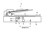
- FIG. 3 is a cross-sectional view illustrating an image reading unit in the image forming apparatus of the present embodiment.
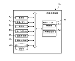
- 1 is a functional block diagram illustrating a configuration of an image forming apparatus according to an exemplary embodiment.
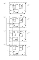
- (A), (c) is a figure which shows the image of the surface of the three originals read by the image reading part, and the image of a back surface
- (b) is the three originals arranged by the image processing part. It is a figure which shows the image of the surface of this, and the image of a back surface.
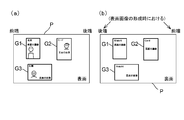
- FIG. (A) is a figure which shows the state which recorded the image of the surface of three originals from the front end side of recording paper
- (b) is the state which recorded the image of the back surface of three originals from the rear end side of recording paper.
- FIG. (A) is a figure which shows the coordinate system corresponding to the recording paper on which the image of the surface of three originals is recorded from the front end side
- (b) is the image of the back side of three originals recorded from the rear end side.
- FIG. 2 is a plan view showing an operation unit and a display unit in the image forming apparatus of the present embodiment.
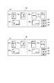
- (A) is a figure which shows the screen of the display part which displayed the image of the surface of three originals read by the image reading part, and the image of a back surface, (b) replaces the position of the image of the back surface of two originals.
- FIG. (A), (b) is the figure used in order to demonstrate the process sequence of the other image processing for correcting the position of the image of the back surface of three originals.
- FIG. 1 is a sectional view showing an image forming apparatus according to an embodiment of the present invention.
- the image forming apparatus 10 according to the present embodiment is an MFP (multifunction peripheral) having a plurality of functions such as a copy function, a printer function, a scanner function, and a facsimile function.
- the image forming apparatus 10 includes an image reading unit 11 and an image forming unit 12.
- the image reading unit 11 includes a scanner that optically reads a document, and generates image data indicating an image of the document.
- the image forming unit 12 prints an image indicated by the image data generated by the image reading unit 11 on a recording sheet.
- the image forming unit 3M for magenta, the image forming unit 3C for cyan, and the image for yellow A forming unit 3Y and an image forming unit 3Bk for black are provided.
- the surface of the photosensitive drum 4 is uniformly charged, the surface of the photosensitive drum 4 is exposed, and an electrostatic latent image is formed on the surface of the photosensitive drum 4.
- the electrostatic latent image on the surface of the photosensitive drum 4 is developed into a toner image, and the toner image on the surface of the photosensitive drum 4 is transferred to the intermediate transfer belt 5.
- a color toner image (image) is formed on the intermediate transfer belt 5.
- This color toner image is secondarily transferred onto the recording paper P conveyed through the first conveyance path 8 from the paper supply unit 7 in the nip region N between the intermediate transfer belt 5 and the secondary transfer roller 6.
- the recording paper P is heated and pressurized by the fixing device 15, the toner image on the recording paper P is fixed by thermocompression bonding, and the recording paper P is discharged to the discharge tray 17 through the discharge roller pair 16.
- the discharge roller pair 16 When recording an image on the back side of the recording paper P, the discharge roller pair 16 is temporarily stopped and then reversely rotated, and the recording paper P is conveyed from the discharge roller pair 16 to the second conveyance path 9.
- the recording paper P is returned to the nip portion N of the first conveyance path 8, whereby the front and back of the recording paper P are reversed, and an image is recorded on the back surface of the recording paper P.
- FIG. 2 is a cross-sectional view showing a mechanical configuration of the image reading unit 11 of the present embodiment.
- the image reading unit 11 includes a document cover 20 and a scanner unit 30.
- a hinge is provided on one side of the upper surface of the scanner unit 30, and the document cover 20 is supported by the hinge so as to be opened and closed, so that the user can open and close the document cover 20.
- the platen glass (document table) 31 of the scanner unit 30 is opened so that the document can be placed on the platen glass 31.
- the document cover 20 is closed, the document cover 20 is closed.
- the scanner unit 30 irradiates the original with light from the light source 32A of the carriage 32 via the platen glass 31 while moving the carriage 32 and the optical system unit 33 in the sub-scanning direction X while maintaining a predetermined speed relationship.
- the light reflected by the document is reflected by the mirror 32C of the carriage 32. Further, this light is reflected by the mirror 33 A and the mirror 33 B of the optical system unit 33 and enters the CCD sensor 35 through the condenser lens 34.
- the condenser lens 34 forms an image of the original on the light receiving surface of the CCD sensor 35, and the CCD sensor 35 repeatedly reads the original image in the main scanning direction Y (direction orthogonal to the sub-scanning direction X).
- FIG. 3 is a functional block diagram showing the main internal configuration of the image forming apparatus 10.
- the image forming apparatus 10 includes a control unit 41, a display unit 42, an image memory 43, an operation unit 44, a touch panel 45, an image reading unit 11, an image forming unit 12, and a storage unit. 46.
- the display unit 42 includes a liquid crystal display (LCD), an organic EL (OLED: Organic Light-Emitting Diode) display, and the like.
- LCD liquid crystal display
- OLED Organic Light-Emitting Diode
- a touch panel 45 is arranged on the screen of the display unit 42.
- the touch panel 45 is a so-called resistive film type or capacitive type touch panel, and detects a touch (touch) of the user's finger or the like with the touch position along with the touch position, and a detection signal indicating the coordinates of the touch position. Is output to a control unit 51 described later of the control unit 41. Accordingly, the touch panel 45 serves as an operation unit to which a user operation on the screen of the display unit 42 is input.
- the image memory 43 temporarily stores image data of a document read by the image reading unit 11.
- the operation unit 44 includes hard keys such as a determination key and a start key.
- the storage unit 46 is a large-capacity storage device such as an HDD (Hard Disk Drive).
- HDD Hard Disk Drive
- the control unit 41 includes a CPU (Central Processing Unit), a RAM (Random Access Memory), a ROM (Read Only Memory), and the like.
- the control unit 41 functions as the control unit 51 and the image processing unit 54 when the program stored in the ROM or the storage unit 46 is executed by the CPU.
- each said structure of the control unit 41 may be comprised by a hard circuit, respectively, not based on the operation
- the control unit 51 controls the overall operation of the image forming apparatus 10.
- the control unit 51 receives a user operation on the touch panel 45 based on the detection signal output from the touch panel 45.
- the control unit 51 accepts user operations on the hard keys of the operation unit 44.
- the control unit 51 controls the display unit 42 to display an input screen for setting items necessary for the image forming process, an information input screen, an operation guidance for the image forming apparatus 10, and the like.
- the image processing unit 54 performs various image processing on the image data in the image memory 43.
- the image forming apparatus 10 has a function for copying a small document such as a business card or a card (hereinafter referred to as an automatic alignment copying function).
- an automatic alignment copying function When the automatic alignment copying function is executed, the image forming apparatus 10 controls a control unit 51 to control a small document such as a business card or a card placed on the platen glass 31 by a user, and a scanner unit 30 to scan the surface of the document. Then, after the user reverses the front and back of the document, the scanner unit 30 reads the image on the back of the document (second scan).
- the image forming unit 12 forms an image on the front side and the back side image of the original on the front side and the back side of the recording paper, and the image on the front side and the back side of the original are recorded on the recording paper.
- the front and back surfaces are overlapped with each other in position. Thereby, the user can cut out a copy of a business card, a card, or the like from one sheet of recording paper. Further, it is possible to simultaneously read images on the front and back surfaces of a plurality of small originals and cut out copies of these originals from a single sheet of recording paper.
- the user places three originals G1, G2, and G3 on the platen glass 31 as shown in FIG.
- the scanner unit 30 reads the entire image of the scan region S including the originals G1, G2, and G3 in the first scan, and reads the entire image of the scan region S (the original images G1, G2, and G3).
- Image data indicating the image of the front surface is stored in the image memory 43.
- the images of the surfaces of the originals G1, G2, and G3 are obtained by using the originals G1, G2, and G3 placed on the platen glass 31 from the inside of the scanner unit 30 as the platen. The state seen through the glass 31 is shown.
- the image processing unit 54 detects each of the four sides forming each document G1, G2, G3 based on the image data indicating the entire image of the scan area S stored in the image memory 43, and separately for each document G1, G2, G3. Then, a rectangular area surrounded by the four sides of the document is detected as an image on the surface of the document.
- the image processing unit 54 uses a known technique to determine each linear boundary where the density difference between the inner side and the outer side is equal to or greater than a preset threshold value based on the image data indicating the entire image of the scan region S. Detected as an edge, and a rectangular area surrounded by four edges (four sides) is detected as an image on the surface of one document.
- the image processing unit 54 has two end sides ma of the end sides (four sides) that divide the image on the surface of each document along the main scanning direction Y.
- the orientation of the image on the surface of each document is changed by rotating the image on the surface of each document so that the other two edges mb are along the sub-scanning direction X.
- the user places the originals G1, G2, and G3 on the platen glass 31 again with their front and back reversed.
- the scanner unit 30 reads the entire image of the scan area S including the originals G1, G2, and G3 by the second scan, and the entire image of the scan area S (respective originals G1, G2, and G3).
- the image memory 43 is stored in the image memory 43.
- the image processing unit 54 detects four sides of each of the originals G1, G2, and G3 based on the image data indicating the entire image of the scan area S stored in the image memory 43. Is detected as an image on the back side of the document.
- the image processing unit 54 has two end sides ma of the end sides (four sides) that define the image on the back side of each document along the main scanning direction Y.
- the image on the back side of each document is rotated so that the other two edges mb are along the sub-scanning direction X, and the orientation of the image on the back side of each document is changed.
- the image processing unit 54 compares the entire image of the scan area S by the first scan shown in FIG. 4A and the entire image of the scan area S by the second scan shown in FIG.
- the images in which the vertical and horizontal sizes of the rectangular areas are the same or close to each other and the closest positions in the entire image of the scan area S are combined as a pair of images forming the front and back surfaces of one document.
- the image processing unit 54 combines the front and back images of the original G1, combines the front and back images of the original G2, and combines the front and back images of the original G3. Combine.
- the “images whose positions are closest to each other” refer to images having the largest image overlapping area between the image on the front side and the image on the back side of the document, for example.
- the image processing unit 54 for each original G1, G2, and G3 is arranged so that the image on the back side of the original coincides with the image on the front side of the original. Rotate or move the back image.
- the image processing unit 54 matches the upper left corner of the image on the front side of the document with the upper left corner of the image on the back side of the document, and the upper side and the left side of the image on the front side of the document are on the upper side and the left side of the image on the back side of the document.
- the image on the back side of the document is rotated or moved so as to match. In this way, the image processing unit 54 arranges the front and back images of the originals G1, G2, and G3 at the same position in the entire image of the scan region S.
- the image processing unit 54 rotates or moves the image on the back side of the document so that it matches the position of the image on the front surface of the document in the entire image of the scan region S.
- the image on the front surface of the document may be rotated or moved so as to coincide with the position of the image on the back surface of the document in the entire image of the scan region S.
- the control unit 51 causes the image forming unit 12 to form an image on the front surface of the recording paper P as described above, and then reverses the front and back of the recording paper P to form an image on the back surface of the recording paper P.
- the image on the back side is the above because of the structure of the image forming apparatus 10 shown in FIG.
- the image is formed from the rear end side of the recording paper P when the front image is formed. That is, after the images on the front surfaces of the originals G1, G2, and G3 shown in FIG.
- FIGS. 5 (a) and 5 (b) the images on the front and back of the originals G1, G2, and G3 are shifted from each other between the front and back surfaces of the recording paper P. Therefore, the front and back images of the originals G1, G2, and G3 cannot be overlapped with each other as they are.
- the image processing unit 54 overlaps the images on the front side and the back side of each of the originals G 1, G 2, G 3 with each other between the front side and the back side of the recording paper P. For this purpose, the images on the back side of the originals G1, G2, and G3 shown in FIG. 4D are moved or rotated.
- the image processing unit 54 sets the front end side and the rear end side of the recording paper P, and the entire image of the scan area S is recorded. A position overlapping the upper corner of the front end of the paper P is set, and this position is set as the origin. At the same time, the image processing unit 54 sets the coordinates at which the entire image of the scan area S overlaps the other three corners of the recording paper P.
- the image processing unit 54 defines a coordinate system A as shown in FIG. 6A for the entire image of the scan region S based on the origin and the three coordinates, and the surface of each document G1, G2, G3. For each image, the coordinates of each corner of the surface image are calculated. It should be noted that the corner coordinates of the image on the surface of the document are the coordinates of the point where the two edges that define the surface image intersect.
- the image processing unit 54 sets the front end side and the rear end side of the recording paper P, and the entire image of the scan area S is displayed. A position overlapping the upper corner of the front edge of the recording paper P is set, and this position is set as the origin. At the same time, the image processing unit 54 sets the coordinates at which the entire image of the scan area S overlaps the other three corners of the recording paper P.
- the image processing unit 54 defines a coordinate system B as shown in FIG. 6B in the entire image of the scan region S based on these origins and three coordinates.
- the image processing unit 54 is based on the coordinates of each corner of the front image in the coordinate system A and the coordinates of each corner of the recording paper P for each image on the back side of each document G1, G2, G3. Then, the coordinates of each corner of the image on the back surface where the image on the front surface and the image on the back surface of the document overlap with each other between the front surface and the back surface of the recording paper P are calculated. Note that the corner coordinates of the image on the back side of the document are the coordinates of the point where the two edges that define the image on the back side intersect.
- the image processing unit 54 sets the coordinates of each corner of the recording paper P to (0, 0), (Xmax, 0), (0, Ymax), (Xmax, Ymax), and the coordinates of each corner of the surface image are (xa1, ya1), (xa2, ya2), (xa3, ya3), (xa4, ya4) for each surface image of each document G1, G2, G3. To do. Further, the image processing unit 54 sets the coordinates of each corner of the recording paper P in the coordinate system B shown in FIG.
- the image processing unit 54 then coordinates (xb1, yb1), (xb2, yb2), (xb3) of each corner of the back image in the coordinate system B based on the following equations (1) to (4). , Yb3), (xb4, yb4).
- Each coordinate value Xmax, Ymax corresponds to the size of the recording paper P.
- the image processing unit 54 sets the coordinates of each corner of the images on the back side of each document G1, G2, G3 in the coordinate system B to (xb1, yb1), (xb2, yb2), (xb3, yb3) and (xb4, yb4) are calculated.
- the image processing unit 54 calculates the coordinates (xb1, yb1), (corners) of the corners of the image on the back surface of each document G1, G2, G3 in the coordinate system B calculated in this way.
- xb2, yb2), (xb3, yb3), (xb4, yb4) are moved to the positions indicated by the images on the back side of the originals G1, G2, G3 in the coordinate system B. That is, the image processing unit 54 matches each corner of the image on the back side of the document with the calculated coordinates of each corner.
- the image processing unit 54 appropriately changes the position and orientation of the image on the back side of each document G1, G2, G3 in the entire image of the scan area S with the front edge of the recording paper P as a reference, thereby forming an image.
- the originals G1, G2, and G3 are formed on the front and back sides of the recording paper P by the unit 12, the originals G1, G2, and G3 are placed between the front and back sides of the recording paper P.
- the front side image and the back side image are made to coincide with each other and overlap.
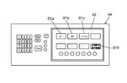
- the control unit 51 causes the display unit 42 to display images of the plurality of touch keys 61a to 61h associated with the respective functions as shown in FIG.
- the user touches the touch key 61h corresponding to the “automatic alignment copying function”.
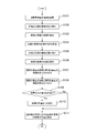
- the control unit 51 activates the automatic alignment copying function (application program) (step S101).
- the control unit 51 causes the scanner unit 30 of the image reading unit 11 to perform the first scan
- the scanner unit 30 reads the images on the surfaces of the originals G1, G2, and G3 on the platen glass 31 (step S102).
- the scanner unit 30 reads the scan area S including the originals G1, G2, and G3 through the platen glass 31, and displays an entire image of the scan area S (including images on the surfaces of the originals G1, G2, and G3). Data is stored in the image memory 43.
- the image processing unit 54 detects four sides of each document G1, G2, and G3 based on the image data indicating the entire image of the scan area S including the image of the surface of each document, and is surrounded by the four sides of the document for each document. A rectangular area is detected as an image on the surface of the document (step S103).
- the image processing unit 54 rotates the image on the surface of the original so that the respective edges defining the image on the surface of the original are along the main scanning direction Y and the sub-scanning direction X for each of the originals G1, G2, and G3.
- the orientation of the image on the surface of the document is corrected (step S104).
- the user places the originals G1, G2, and G3 on the platen glass 31 with their front and back reversed, and operates the start key of the operation unit 44.
- the control unit 51 causes the scanner unit 30 to perform the second scan, and the scanner unit 30 causes the back side of each of the documents G1, G2, and G3 on the platen glass 31.
- image data indicating the entire image of the scan area S is stored in the image memory 43.
- the image processing unit 54 detects four sides of each document G1, G2, and G3 based on image data indicating the entire image of the scan area S including the image on the back side of each document, and is surrounded by the four sides of the document for each document. A rectangular area is detected as an image on the back side of the document (step S106).
- the image processing unit 54 compares the entire image of the scan area S by the first scan shown in FIG. 4A with the entire image of the scan area S by the second scan shown in FIG. In this manner, the front and back images of the original G1 are combined, the front and back images of the original G2 that overlap each other are combined, and the front and back images of the original G3 that overlap each other are combined (step S107). .
- the image processing unit 54 rotates or moves the image on the back side of the document for each of the documents G1, G2, and G3 to superimpose the image on the front surface and the image on the back surface as shown in FIG. (Step S108).
- the image forming apparatus 10 has a function of replacing the images on the back side of the originals G1, G2, and G3 after S108.
- this image replacement process for example, when the user reverses the front and back of each document G1, G2, G3 placed on the platen glass 31, the positions of the documents G1, G2, G3 are erroneously switched. It is done when it is closed.
- the control unit 51 displays images on the front side of the originals G1, G2, and G3 arranged on the platen glass 31 and images on the back side of the originals G1, G2, and G3 on the display unit 42. Display them side by side on the screen.
- the user confirms whether or not the positions of the originals G1, G2, and G3 are erroneously changed by looking at the screen of the display unit 42.
- the user touches the replacement button 62 after touching the images on the back side of the two interchanged originals.
- step S109 When the touch operation on the back image of the two originals and the touch operation on the exchange button 62 are sequentially received by the control unit 51 through the touch panel 45 (“Yes” in step S109), the image processing unit 54 For the image data indicating the entire image of the scan area S including the image, a process of exchanging the positions of the respective images indicating the two touch-operated originals is performed (step S110).
- the image processing unit 54 displays the image in FIG. ),
- the positions of the two originals G1 and G2 in the entire image of the scan area S are interchanged, and for each of the originals G1 and G2, the image on the front surface and the back surface of the original in the entire image of the scan area S are respectively displayed. Match the position of the image.
- step S110 is not performed. In this case, for example, the position of the image on the back surface of each document G1, G2, G3 in the entire image of the scan region S shown in FIG. 9B is maintained without being changed.
- the image on the back side of the document may be turned upside down in the work of inverting the front and back of the document.
- the reverse button 64 is touch-operated.
- the image processing unit 54 touches the image data indicating the entire image of the scan area S. A process of inverting the image on the back side of the operated document is performed.
- the image processing unit 54 sets a coordinate system A as shown in FIG. 6A to obtain the coordinates of each corner of the surface image for each surface image of each document G1, G2, G3.
- a coordinate system B as shown in FIG. 6B is set, and each corner of the image on the back surface is determined for each image on the back surface of each document G1, G2, G3 based on the above equations (1) to (4).
- the coordinates are calculated, and the back image is moved so that the corners of the back image coincide with the coordinates of these corners (step S111). That is, with the front edge of the recording paper P as a reference, the position and orientation of the image on the back surface of each document G1, G2, G3 on the back surface of the recording paper P are appropriately changed.
- each edge of the document is substantially parallel to the main scanning direction Y and the sub-scanning direction X (each edge of the recording paper P), the document can be easily cut out.
- the orientation of the image on the front side of the document is changed, and the image on the back side of the document is combined with the image on the front side of the document, and then based on the above equations (1) to (4), Although the back side image is moved, the image processing unit 54 omits the change of the orientation of the front side image and the superimposition of the back side image on the front side image, and performs the above equations (1) to (4). Based on this, it is also possible to match the image on the front surface of the document with the image on the back surface in the entire image of the scan area S between the front surface and the back surface of the recording paper P only by moving the image on the back surface of the document.
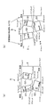
- the image processing unit 54 determines the surface of the original for each of the originals G1, G2, and G3. 10B and the back side image are combined, and in the coordinate system B as shown in FIG. 10B, the back side images of the originals G1, G2, and G3 are classified according to the above formulas (1) to (4). Then, the coordinates of each corner of the image on the back side of the document are calculated so that the image on the front side and the image on the back side of the recording paper P overlap each other in the entire image of the scan area S between the front and back surfaces of the recording paper P. Next, move the image on the back of the document and tilt it.
- pre-scanning by the image reading unit 11 may be performed to detect each edge of the document, and then main scanning by the image reading unit 11 may be performed to read an image of the document.
- the density, contrast, resolution, and the like of the entire image of the scan area S read by the image reading unit 11 may be different.
- FIGS. 1 to 10 are only one embodiment of the present invention, and are not intended to limit the present invention to the configuration and processing.
Landscapes
- Engineering & Computer Science (AREA)
- Multimedia (AREA)
- Signal Processing (AREA)
- Physics & Mathematics (AREA)
- General Physics & Mathematics (AREA)
- Health & Medical Sciences (AREA)
- General Health & Medical Sciences (AREA)
- Biomedical Technology (AREA)
- Editing Of Facsimile Originals (AREA)
- Control Or Security For Electrophotography (AREA)
- Accessory Devices And Overall Control Thereof (AREA)
- Record Information Processing For Printing (AREA)
- Counters In Electrophotography And Two-Sided Copying (AREA)
Abstract
【課題】複数の小さな原稿であっても、各原稿の表面の画像と裏面の画像を、1枚の記録紙の表裏に表裏面の画像位置を合わせた上で重ね合わせて形成可能にする。 【解決手段】本発明の画像形成装置10においては、画像処理部54が、画像読取部11により1回目の走査で読み取られたスキャン領域から原稿の表面の画像を検出し、画像読取部11により2回目の走査で読み取られたスキャン領域から原稿の裏面の画像を検出し、原稿の表面の画像と裏面の画像が記録紙の表面と裏面で一致して重なり合うように、スキャン領域の全体画像における原稿の表面の画像及び裏面の画像を移動又は回転させる。
Description
本発明は、記録紙の表面及び裏面にそれぞれの画像を記録する画像形成装置に関し、特に記録紙の表面及び裏面に形成した画像の位置を合わせる技術に関する。
画像形成装置には、原稿の表面の画像及び裏面の画像を読み取り、記録紙の表面に原稿の表面の画像を記録し、引き続いて記録紙の表裏を反転させて、記録紙の裏面に原稿の裏面の画像を記録することが可能とされたものがある。この場合、記録紙の表面と裏面に形成された各画像の位置を合わせたくても、原稿の表面の画像と裏面の各画像の位置がずれてしまい、正確に重ならない場合がある。
このため、特許文献1では、スキャナーにより読み取られた画像上で、この画像に含まれる記録紙の一辺を抽出して、この画像の原点に対する記録紙の一辺の両端の座標を求め、この記録紙の一辺の両端の座標から、記録紙の縦方向のずれ、横方向のずれ、及び傾きを求めて、画像処理により記録紙のずれや傾きを修正し、更に記録紙の表裏の間での画像のズレを求めて、正確な位置調整を行っている。
また、特許文献2では、記録媒体の表面と裏面に印刷された補正パターンを両面読取り手段で一度に読み取り、それぞれの補正パターンの位置を検出して、検出された両面の補正パターンから印刷位置ずれの補正量を算出し、その算出された補正量に基づいて、両面印刷時における表面と裏面の間での印刷位置のずれを補正している。
ところで、画像形成装置の利用方法として、名刺やカード等の小さな原稿の表面の画像及び裏面の画像を読み取り、この原稿の表面の画像及び裏面の画像を記録紙の表面及び裏面に形成し、この原稿の表面の画像及び裏面の画像を記録紙から切り抜いて、両面に画像が形成された名刺等の小さな原稿を複製するという利用方法がある。この場合も、原稿の表面の画像と裏面の画像を記録紙の表裏で一致させて重ね合わせる必要がある。また、この場合、複数の小さな原稿の表面の画像及び裏面の画像を同時に読み取って、これらの原稿の複製を1枚の記録紙から切り抜くことができるようにするのが望ましい。
しかしながら、特許文献1では、スキャナーにより読み取られた画像の原点を基準として、記録紙のずれや傾きを修正しているため、小さな原稿であっても、同時に画像形成を行うことができず、原稿ごとに画像形成を行うことになる。
また、特許文献2では、記録媒体の表面と裏面に補正パターンを印刷する必要があるので、一般的な名刺やカード等の複製を作成することができない。
本発明は、上記の事情に鑑みなされたものであり、複数の小さな原稿であっても、各原稿の表面の画像と裏面の画像を、1枚の記録紙の表裏に表裏面の画像位置を合わせた上で重ね合わせて形成可能にすることを目的とする。
本発明の一局面に係る画像形成装置は、原稿の画像を読み取る画像読取部と、前記画像読取部に、前記原稿の表面の画像を1回目の走査で読み取らせ、その後に、前記原稿の裏面の画像を2回目の走査で読み取らせる制御部と、前記画像読取部により1回目の走査で読み取られたスキャン領域の全体画像から前記原稿の表面の画像を検出し、前記画像読取部により2回目の走査で読み取られたスキャン領域の全体画像から前記原稿の裏面の画像を検出し、前記原稿の表面の画像又は裏面の画像を移動又は回転させて、前記スキャン領域の全体画像における前記原稿の表面の画像又は裏面の画像の位置を、前記記録紙の表面と裏面とで一致して重なり合う位置に移動させる画像処理を行う画像処理部と、前記制御部による制御の下、前記画像処理部による前記画像処理後の前記1回目で読み取られた前記スキャン領域の全体画像を記録紙の表面に形成し、前記画像処理部による前記画像処理後の前記2回目で読み取られた前記スキャン領域の全体画像を記録紙の裏面に形成する画像形成部と、を備えるものである。
本発明によれば、複数の小さな原稿であっても、各原稿の表面の画像と裏面の画像を、1枚の記録紙の表裏にそれぞれ表裏面の画像位置を合わせた上で重ね合わせて形成することが可能となる。
以下、本発明の実施形態について図面を参照して説明する。
図1は、本発明の実施形態にかかる画像形成装置を示す断面図である。本実施形態の画像形成装置10は、例えば、コピー機能、プリンター機能、スキャナー機能、及びファクシミリ機能のような複数の機能を兼ね備えたMFP(複合機)である。この画像形成装置10は、画像読取部11と、画像形成部12とを備えている。
画像読取部11は、原稿を光学的に読み取るスキャナーを有し、この原稿の画像を示す画像データを生成する。
画像形成部12は、画像読取部11で生成された画像データによって示される画像を記録紙に印刷するものであり、マゼンタ用の画像形成ユニット3M、シアン用の画像形成ユニット3C、イエロー用の画像形成ユニット3Y、及びブラック用の画像形成ユニット3Bkを備えている。各画像形成ユニット3M、3C、3Y、及び3Bkのいずれにおいても、感光体ドラム4の表面を均一帯電させ、感光体ドラム4の表面を露光して、感光体ドラム4の表面に静電潜像を形成し、感光体ドラム4の表面の静電潜像をトナー像に現像して、感光体ドラム4の表面のトナー像を、中間転写ベルト5に転写する。これにより、カラーのトナー像(画像)が中間転写ベルト5上に形成される。このカラーのトナー像は、中間転写ベルト5と2次転写ローラー6の間のニップ域Nにおいて給紙部7から第1搬送路8を通じて搬送されてきた記録紙Pに2次転写させる。
この後、定着装置15で記録紙Pが加熱及び加圧されて、記録紙P上のトナー像が熱圧着により定着され、更に記録紙Pが排出ローラー対16を通じて排出トレイ17に排出される。
また、記録紙Pの裏面にも画像を記録する場合は、排出ローラー対16が一旦停止されてから逆回転され、記録紙Pが排出ローラー対16から第2搬送路9へと搬送されて、記録紙Pが第1搬送路8のニップ部Nに戻され、これにより記録紙Pの表裏が反転されて、記録紙Pの裏面に画像が記録される。
図2は、本実施形態の画像読取部11の機械構成を示す断面図である。図2に示すように、画像読取部11は、原稿カバー20及びスキャナー部30を備えている。スキャナー部30の上面の一辺には、ヒンジが設けられており、このヒンジにより原稿カバー20が開閉可能に支持されて、利用者による原稿カバー20の開閉操作が可能にされている。
原稿カバー20が開かれたときには、スキャナー部30のプラテンガラス(原稿台)31が開放されて、プラテンガラス31上に原稿を載置することができ、原稿カバー20が閉じられると、原稿カバー20によりプラテンガラス31上に載置された原稿が押さえられる。スキャナー部30では、キャリッジ32及び光学系ユニット33を所定の速度関係を維持して副走査方向Xに移動させつつ、キャリッジ32の光源32Aの光を、プラテンガラス31を介して原稿に照射し、原稿で反射された光をキャリッジ32のミラー32Cで反射する。更に、この光は、光学系ユニット33のミラー33A及びミラー33Bで反射されて、集光レンズ34を通じてCCDセンサー35に入射する。このとき、集光レンズ34がCCDセンサー35の受光面に原稿の画像を結像し、CCDセンサー35が原稿の画像を主走査方向Y(副走査方向Xと直交する方向)に繰り返し読取る。
図3は、画像形成装置10の主要内部構成を示す機能ブロック図である。図3に示すように画像形成装置10は、制御ユニット41と、表示部42と、画像メモリー43と、操作部44と、タッチパネル45と、画像読取部11と、画像形成部12と、記憶部46とを備えている。
表示部42は、液晶ディスプレイ(LCD:Liquid Crystal Display)や有機EL(OLED:Organic Light-Emitting Diode)ディスプレイなどから構成される。
表示部42の画面には、タッチパネル45が配置されている。タッチパネル45は、所謂抵抗膜方式や静電容量方式などのタッチパネルであって、タッチパネル45に対するユーザーの指などの接触(タッチ)をその接触位置とともに検知して、その接触位置の座標を示す検知信号を制御ユニット41の後述する制御部51などに出力する。従って、タッチパネル45は、表示部42の画面に対するユーザー操作が入力される操作部としての役割を果たす。
画像メモリー43は、画像読取部11により読取られた原稿の画像データを一時的に記憶する。
操作部44は、決定キー、スタートキーなどのハードキーを備えている。
記憶部46は、HDD(Hard Disk Drive)などの大容量の記憶装置である。
制御ユニット41は、CPU(Central Processing Unit)、RAM(Random Access Memory)、及びROM(Read Only Memory)などから構成される。この制御ユニット41は、上記のROMまたは記憶部46に記憶されたプログラムが上記のCPUで実行されることにより、制御部51、及び画像処理部54として機能する。なお、制御ユニット41の上記の各構成は、プログラムに基づく動作によらず、それぞれハード回路により構成されてもよい。
制御部51は、画像形成装置10の全体的な動作制御を司る。制御部51は、タッチパネル45から出力される検知信号に基づき、タッチパネル45に対するユーザー操作を受け付ける。また、制御部51は、操作部44のハードキーに対するユーザー操作を受け付ける。
制御部51は、表示部42を制御して、画像形成処理に必要な設定項目の入力画面、情報の入力画面、あるいは画像形成装置10の操作ガイダンスなどを表示させる。
画像処理部54は、画像メモリー43内の画像データに対して各種の画像処理を施す。
ここで、画像形成装置10は、名刺やカード等の小さな原稿を複製するための機能(以下、自動整列複写機能と称す)を有する。画像形成装置10は、この自動整列複写機能の実行時には、制御部51の制御により、ユーザーによりプラテンガラス31上に載置された名刺やカード等の小さな原稿を、スキャナー部30により当該原稿の表面の画像を読み取らせ(1回目の走査)、続いてユーザーが原稿の表裏を反転させた後、スキャナー部30に原稿の裏面の画像を読み取らせる(2回目の走査)。この後、制御部51による制御の下、画像形成部12により原稿の表面の画像及び裏面の画像が記録紙の表面及び裏面に形成され、かつ原稿の表面の画像及び裏面の画像が記録紙の表面と裏面の間で互いに位置を合わせて重ね合わされる。これにより、ユーザーは、名刺やカード等の複製を1枚の記録紙から切り抜くことができる。また、複数の小さな原稿の表面の画像及び裏面の画像を同時に読み取って、これらの原稿の複製を1枚の記録紙から切り抜くことまでが可能になる。
例えば、ユーザーは、図4(a)に示すように3つの原稿G1、G2、G3をプラテンガラス31上に載置する。制御部51による制御の下、スキャナー部30は1回目の走査で各原稿G1、G2、G3を含むスキャン領域S全体の画像を読み取り、スキャン領域Sの全体画像(各原稿G1、G2、G3の表面の画像を含む)を示す画像データを画像メモリー43に記憶する。なお、図4(a)~(d)に示す各原稿G1、G2、G3の表面の画像は、スキャナー部30の内部からプラテンガラス31に載置された各原稿G1、G2、G3を、プラテンガラス31を通して見た状態を示す。
画像処理部54は、画像メモリー43に記憶されたスキャン領域Sの全体画像を示す画像データに基づき、各原稿G1、G2、G3をなすそれぞれの四辺を検出し、各原稿G1、G2、G3別に、原稿の四辺で囲まれる矩形領域を原稿の表面の画像として検出する。
プラテンガラス31上に載置された3つの原稿G1、G2、G3の画像を含むスキャン領域Sの全体画像においては、上記キャリッジ32の光源32Aからの照明により、各原稿の各端辺に沿って影が生じ、各原稿の各端辺の内側と外側の濃度差が大きくなる。そこで、画像処理部54は、既知の技術を用いて、スキャン領域Sの全体画像を示す画像データに基づき、内側と外側の濃度差が、予め設定された閾値以上となる直線状の境界を各端辺として検出し、4つの端辺(四辺)で囲まれる矩形領域を一つの原稿の表面の画像として検出する。
そして、画像処理部54は、図4(b)に示すように、各原稿の表面の画像を区画する各端辺(四辺)のうちの2つの端辺maが主走査方向Yに沿うと共に、他の2つの端辺mbが副走査方向Xに沿うように、各原稿の表面の画像を回転させて、各原稿の表面の画像の向きを変更する。
引き続いて、図4(c)に示すように、ユーザーは、各原稿G1、G2、G3を、それらの表裏を反転させてプラテンガラス31上に再び載置する。制御部51による制御の下、スキャナー部30は、2回目の走査により各原稿G1、G2、G3を含むスキャン領域S全体の画像を読み取り、スキャン領域Sの全体画像(各原稿G1、G2、G3の裏面の画像を含む)を示す画像データを画像メモリー43に記憶させる。
画像処理部54は、画像メモリー43に記憶されたスキャン領域Sの全体画像を示す画像データに基づき、上記と同様にして、各原稿G1、G2、G3の四辺を検出して、原稿別に、原稿の四辺で囲まれる矩形領域を原稿の裏面の画像として検出する。
そして、画像処理部54は、図4(d)に示すように、各原稿の裏面の画像を区画する各端辺(四辺)のうちの2つの端辺maが主走査方向Yに沿うと共に、他の2つの端辺mbが副走査方向Xに沿うように、各原稿の裏面の画像を回転させて、各原稿の裏面の画像の向きを変更する。
そして、画像処理部54は、図4(a)に示す1回目の走査によるスキャン領域Sの全体画像と、図4(c)に示す2回目の走査によるスキャン領域Sの全体画像とを比較して、矩形領域の縦横サイズが互いに一致又は一致に近似し、かつ、スキャン領域Sの全体画像における位置が最も近い画像同士を、1つの原稿の表面と裏面をなす一対の画像同士として組み合わせる。このようにして、画像処理部54は、原稿G1の表面の画像と裏面の画像とを組み合わせ、原稿G2の表面の画像と裏面の画像とを組み合わせ、原稿G3の表面の画像と裏面の画像とを組み合わせる。なお、上記「位置が最も近い画像同士」とは、例えば、原稿の表面の画像と裏面の画像との間で、画像位置が重なり合う領域が最も大きい画像同士をいう。
更に、画像処理部54は、各原稿G1、G2、G3別に、図4(d)に示すように、原稿の表面の画像に対して原稿の裏面の画像が一致して重なるように、原稿の裏面の画像を回転又は移動させる。例えば、画像処理部54は、原稿の表面の画像の左上角が原稿の裏面の画像の左上角に一致し、かつ原稿の表面の画像の上辺及び左辺が原稿の裏面の画像の上辺及び左辺に一致するように、原稿の裏面の画像を回転又は移動させる。このようにして、画像処理部54は、スキャン領域Sの全体画像において、各原稿G1、G2、G3の表面の画像と裏面の画像とを、それぞれ同じ位置に配置する。
なお、本実施形態では、画像処理部54は、スキャン領域Sの全体画像における原稿の表面の画像の位置に一致するように、原稿の裏面の画像を回転又は移動させるものとしているが、これに限られず、スキャン領域Sの全体画像における原稿の裏面の画像の位置に一致するように、原稿の表面の画像を回転又は移動させてもよい。
次に制御部51は、画像形成部12に、上記のように記録紙Pの表面に画像を形成させた後、記録紙Pの表裏を反転させて、記録紙Pの裏面にも画像を形成させる。このとき、制御部51は、画像形成部12に、表面の画像を記録紙Pの前端側から画像形成させた場合、図1に示した画像形成装置10の構造上、裏面の画像は、上記表面の画像の形成時の記録紙P後端側から画像形成させることになる。すなわち、図4(b)に示す各原稿G1、G2、G3の表面の画像が記録紙Pの表面に画像形成された後、図4(d)に示す各原稿G1、G2、G3の裏面の画像がそのまま記録紙Pの裏面に画像形成される。この場合、図5(a)、(b)に示すように記録紙Pの表面と裏面の間で、各原稿G1、G2、G3の表面の画像と裏面の画像がずれて配置される。従って、このままでは、各原稿G1、G2、G3の表面の画像と裏面の画像とを表裏一体に重なり合わせることができない。
そこで、画像処理部54は、画像形成部12による画像形成前に、記録紙Pの表面と裏面の間で各原稿G1、G2、G3の表面の画像と裏面の画像を互いに一致して重なり合わせるために、図4(d)に示す各原稿G1、G2、G3の裏面の画像を移動又は回転させる。
例えば、図4(b)に示す1回目の走査によるスキャン領域Sの全体画像において、画像処理部54は、記録紙Pの前端側及び後端側を設定し、スキャン領域Sの全体画像が記録紙Pの前端の上側角に重なる位置を設定し、この位置を原点として設定する。これと共に、画像処理部54は、スキャン領域Sの全体画像が記録紙Pの他の3つの角に重なるそれぞれの座標を設定する。画像処理部54は、これらの原点及び3つの座標に基づき、スキャン領域Sの全体画像に、図6(a)に示すような座標系Aを定義し、各原稿G1、G2、G3の表面の画像別に、表面の画像の各角の座標を算出する。なお、原稿の表面の画像の角の座標は、表面の画像を区画する2つの端辺が交差する点の座標である。
また、図4(d)に示す2回目の走査によるスキャン領域Sの全体画像においても、画像処理部54は、記録紙Pの前端側及び後端側を設定し、スキャン領域Sの全体画像が記録紙Pの前端の上側角に重なる位置を設定し、この位置を原点として設定する。これと共に、画像処理部54は、スキャン領域Sの全体画像が記録紙Pの他の3つの角に重なるそれぞれの座標を設定する。画像処理部54は、これらの原点及び3つの座標に基づき、スキャン領域Sの全体画像に、図6(b)に示すような座標系Bを定義する。
そして、画像処理部54は、この座標系Bにおいて、各原稿G1、G2、G3の裏面の画像別に、座標系Aにおける表面の画像の各角の座標及び記録紙Pの各角の座標に基づき、記録紙Pの表面と裏面の間で原稿の表面の画像と裏面の画像が互いに一致して重なり合う裏面の画像の各角の座標を算出する。なお、原稿の裏面の画像の角の座標は、裏面の画像を区画する2つの端辺が交差する点の座標である。
例えば、画像処理部54は、図6(a)に示す座標系Aにおいて、記録紙Pの各角の座標を(0,0)、(Xmax,0)、(0,Ymax)、(Xmax,Ymax)とし、各原稿G1、G2、G3の表面の画像別に、表面の画像の各角の座標を(xa1,ya1)、(xa2,ya2)、(xa3,ya3)、(xa4,ya4)とする。また、画像処理部54は、図6(b)に示す座標系Bにおいて、記録紙Pの各角の座標を(0,0)、(Xmax,0)、(0,Ymax)、(Xmax,Ymax)とし、各原稿G1、G2、G3の裏面の画像別に、裏面の画像の各角の座標を(xb1,yb1)、(xb2,yb2)、(xb3,yb3)、(xb4,yb4)とする。
そして、画像処理部54は、次のような各式(1)乃至(4)に基づき、座標系Bにおける裏面の画像の各角の座標(xb1,yb1)、(xb2,yb2)、(xb3,yb3)、(xb4,yb4)を求める。なお、各座標値Xmax、Ymaxは、記録紙Pのサイズに対応している。
(xb1,yb1)=((Xmax-xa1),ya1) …(1)
(xb2,yb2)=((Xmax-xa2),ya2) …(2)
(xb3,yb3)=((Xmax-xa3),ya3) …(3)
(xb4,yb4)=((Xmax-xa4),ya4) …(4)
(xb2,yb2)=((Xmax-xa2),ya2) …(2)
(xb3,yb3)=((Xmax-xa3),ya3) …(3)
(xb4,yb4)=((Xmax-xa4),ya4) …(4)
画像処理部54は、このようにして、座標系Bにおける各原稿G1、G2、G3の裏面の画像のそれぞれについて、各角の座標を(xb1,yb1)、(xb2,yb2)、(xb3,yb3)、(xb4,yb4)として算出する。画像処理部54は、図6(b)に示すように、このように算出した、座標系Bにおける各原稿G1、G2、G3の裏面の画像についての各角の座標(xb1,yb1)、(xb2,yb2)、(xb3,yb3)、(xb4,yb4)が示す位置に、座標系Bにおける各原稿G1、G2、G3の裏面の画像の位置を移動させる。すなわち、画像処理部54は、上記算出した各角の座標に、原稿の裏面の画像の各角を一致させる。
このように、画像処理部54は、記録紙Pの前端を基準にして、スキャン領域Sの全体画像における各原稿G1、G2、G3の裏面の画像の位置及び向きを適宜変更して、画像形成部12により各原稿G1、G2、G3の表面の画像及び裏面の画像が記録紙Pの表面及び裏面に形成されたときには、記録紙Pの表面と裏面の間で各原稿G1、G2、G3の表面の画像と裏面の画像とを互いに一致させて重なり合わせる。この結果、記録紙Pに画像形成されている各原稿G1、G2、G3の画像部分を、記録紙Pから切り抜くと、表裏面に画像が形成された名刺やカード等を、1枚の記録紙から作成することが可能になる。
次に、画像形成装置10における、原稿の表面の画像及び裏面の画像を読み取って、原稿の表面の画像と裏面の画像を記録紙の表面と裏面の間で互いに一致させて重ね合わせるまでの処理手順を、図7のフローチャートなどを参照して説明する。
まず、ユーザーは、例えば図4(a)に示すように3つの原稿G1、G2、G3をプラテンガラス31上に載置する。このとき、制御部51は、表示部42に、図8に示すようにそれぞれの機能に対応付けられた複数のタッチキー61a~61hの画像等を表示させる。ユーザーは、上記の「自動整列複写機能」に対応するタッチキー61hをタッチ操作する。このタッチ操作がタッチパネル45を通じて制御部51で受け付けられると、制御部51が、自動整列複写機能(アプリケーションプログラム)を起動させる(ステップS101)。
そして、ユーザーが、操作部44のスタートキーを操作して、この操作が制御部51で受け付けられると、制御部51は、画像読取部11のスキャナー部30に1回目の走査を行わせて、スキャナー部30によりプラテンガラス31上の各原稿G1、G2、G3の表面の画像を読み取らせる(ステップS102)。スキャナー部30は、プラテンガラス31越しに、各原稿G1、G2、G3を含むスキャン領域Sを読み取り、スキャン領域Sの全体画像(各原稿G1、G2、G3の表面の画像を含む)を示す画像データを画像メモリー43に記憶する。
画像処理部54は、各原稿の表面の画像を含むスキャン領域Sの全体画像を示す画像データに基づき、各原稿G1、G2、G3の四辺を検出して、原稿別に、原稿の四辺で囲まれる矩形領域を原稿の表面の画像として検出する(ステップS103)。
そして、画像処理部54は、各原稿G1、G2、G3別に、原稿の表面の画像を区画する各端辺が主走査方向Y及び副走査方向Xに沿うように、原稿の表面の画像を回転させて、原稿の表面の画像の向きを修正する(ステップS104)。
続いて、ユーザーは、例えば図4(c)に示すように各原稿G1、G2、G3を、それらの表裏を反転させてプラテンガラス31上に再び載置し、操作部44のスタートキーを操作する。このスタートキーの操作が制御部51で受け付けられると、制御部51は、スキャナー部30に2回目の走査を行わせて、スキャナー部30によりプラテンガラス31上の各原稿G1、G2、G3の裏面の画像を読み取らせ(ステップS105)、スキャン領域Sの全体画像(各原稿G1、G2、G3の裏面の画像を含む)を示す画像データを画像メモリー43に記憶させる。
画像処理部54は、各原稿の裏面の画像を含むスキャン領域Sの全体画像を示す画像データに基づき、各原稿G1、G2、G3の四辺を検出して、原稿別に、原稿の四辺で囲まれる矩形領域を原稿の裏面の画像として検出する(ステップS106)。
更に画像処理部54は、図4(a)に示す1回目の走査によるスキャン領域Sの全体画像と図4(c)に示す2回目の走査によるスキャン領域Sの全体画像を比較して、上述した手法により、原稿G1の表面の画像と裏面の画像を組み合わせ、互いに重なり合う原稿G2の表面の画像と裏面の画像を組み合わせ、互いに重なり合う原稿G3の表面の画像と裏面の画像を組み合わせる(ステップS107)。
そして、画像処理部54は、各原稿G1、G2、G3別に、図4(d)に示すように原稿の裏面の画像を回転又は移動させて、原稿の表面の画像と裏面の画像を重ね合わせる(ステップS108)。
画像形成装置10は、S108の後に各原稿G1、G2、G3の裏面の画像を入れ替える機能を有する。この画像の入れ替え処理は、例えば、ユーザーがプラテンガラス31上に載置されている各原稿G1、G2、G3の表裏を反転させる作業で該各原稿G1、G2、G3の位置が誤って入れ替わってしまったときに行われる。
制御部51は、例えば図9(a)に示すようにプラテンガラス31に配置された各原稿G1、G2、G3の表面の画像と各原稿G1、G2、G3の裏面の画像を表示部42の画面に並べて表示させる。ユーザーは、この表示部42の画面を見て、各原稿G1、G2、G3の位置が誤って入れ替わっているか否かを確認する。ユーザーは、各原稿G1、G2、G3の位置が入れ替わっていると判断したときは、入れ替わっている2つの原稿の裏面の画像をタッチ操作してから、入れ替えボタン62をタッチ操作する。
この2つの原稿の裏面の画像に対するタッチ操作及び入れ替えボタン62に対するタッチ操作がタッチパネル45を通じて制御部51で順次受け付けられると(ステップS109で「Yes」)、画像処理部54は、各原稿の裏面の画像を含むスキャン領域Sの全体画像を示す画像データに対して、タッチ操作された2つの原稿を示す各画像の位置を入れ替える処理を行う(ステップS110)。
例えば、図9(a)において2つの原稿G1の裏面の画像と原稿G2の裏面の画像がタッチ操作されて、入れ替えボタン62がタッチ操作された場合は、画像処理部54は、図9(b)に示すように、スキャン領域Sの全体画像における2つの原稿G1、G2の位置を入れ替えて、各原稿G1、G2のそれぞれについて、スキャン領域Sの全体画像においての原稿の表面の画像と裏面の画像の位置を一致させる。
また、各原稿G1、G2、G3の位置が入れ替わっておらず、OKボタン63がタッチ操作されて、OKボタン63のタッチ操作がタッチパネル45を通じて制御部51で受け付けられると(ステップS109で「No」)、ステップS110の処理は行われない。この場合は、例えば図9(b)に示す、スキャン領域Sの全体画像における各原稿G1、G2、G3の裏面の画像の位置が変更されることなく維持される。
なお、原稿の表裏を反転させる作業で、該原稿の裏面の画像の上下が逆になることもある。制御部51が表示部42に表示させている、プラテンガラス31に配置された各原稿G1、G2、G3の表面の画像と各原稿G1、G2、G3の裏面の画像のうち、ユーザーは、上下が逆になっている原稿をタッチ操作して選択してから、反転ボタン64をタッチ操作する。この原稿の裏面の画像に対するタッチ操作及び反転ボタン64に対するタッチ操作がタッチパネル45を通じて制御部51で順次受け付けられると、画像処理部54は、スキャン領域Sの全体画像を示す画像データに対して、タッチ操作された原稿の裏面の画像の上下を反転させる処理を行う。
更に、画像処理部54は、図6(a)に示すような座標系Aを設定して、各原稿G1、G2、G3の表面の画像別に、表面の画像の各角の座標を求め、また図6(b)に示すような座標系Bを設定して、各原稿G1、G2、G3の裏面の画像別に、上記各式(1)~(4)に基づき、裏面の画像の各角の座標を算出し、これらの角の座標に裏面の画像の各角が一致するように該裏面の画像を移動させる(ステップS111)。すなわち、記録紙Pの前端を基準にして、該記録紙Pの裏面における各原稿G1、G2、G3の裏面の画像の位置及び向きを適宜変更する。これにより、記録紙Pの表面と裏面の間で各原稿G1、G2、G3の表面の画像と裏面の画像が互いに一致して重なり合い、名刺やカード等の複製として、1枚の記録紙Pから切り抜くことが可能となる。また、本実施形態によれば、原稿の各端辺が主走査方向Y及び副走査方向X(記録紙Pの各端辺)と略平行なため、原稿を容易に切り抜くことができる。
なお、上記実施形態では、原稿の表面の画像の向きを変更し、この原稿の表面の画像に原稿の裏面の画像を組み合わせてから、上記各式(1)~(4)に基づき、原稿の裏面の画像を移動させているが、画像処理部54は、表面の画像の向きの変更及び表面の画像に対する裏面の画像の重ね合わせを省略して、上記各式(1)~(4)に基づき、原稿の裏面の画像を移動させるだけでも、記録紙Pの表面と裏面の間で、スキャン領域Sの全体画像における原稿の表面の画像と裏面の画像を一致させることも可能である。
例えば、図10(a)に示すように座標系Aにおける各原稿G1、G2、G3の表面の画像が傾いていても、画像処理部54は、各原稿G1、G2、G3別に、原稿の表面の画像と裏面の画像を組み合わせた後、図10(b)に示すように座標系Bにおいて、各原稿G1、G2、G3の裏面の画像別に、上記各式(1)~(4)に基づき、原稿の裏面の画像の各角の座標を算出して、記録紙Pの表面と裏面の間で原稿の表面の画像と裏面の画像が、スキャン領域Sの全体画像において互いに一致して重なるように、原稿の裏面の画像を移動させて傾ける。
また、原稿の各端辺を検出するために画像読取部11によるプレスキャンを行い、続いて原稿の画像を読み取るために画像読取部11による本スキャンを行ってもよく、プレスキャンと本スキャンの間で、画像読取部11により読み取られたスキャン領域Sの全体画像の濃度、コントラスト、解像度などを異ならせても構わない。
また、図1乃至図10を用いて説明した構成及び処理は、本発明の一実施形態に過ぎず、本発明を当該構成及び処理に限定する趣旨ではない。
10 画像形成装置
11 画像読取部
12 画像形成部
41 制御ユニット
42 表示部
43 画像メモリー
44 操作部
45 タッチパネル
46 記憶部
51 制御部
54 画像処理部
11 画像読取部
12 画像形成部
41 制御ユニット
42 表示部
43 画像メモリー
44 操作部
45 タッチパネル
46 記憶部
51 制御部
54 画像処理部
Claims (6)
- 原稿の画像を読み取る画像読取部と、
前記画像読取部に、前記原稿の表面の画像を1回目の走査で読み取らせ、その後に、前記原稿の裏面の画像を2回目の走査で読み取らせる制御部と、
前記画像読取部により1回目の走査で読み取られたスキャン領域の全体画像から前記原稿の表面の画像を検出し、前記画像読取部により2回目の走査で読み取られたスキャン領域の全体画像から前記原稿の裏面の画像を検出し、前記原稿の表面の画像又は裏面の画像を移動又は回転させて、前記スキャン領域の全体画像における前記原稿の表面の画像又は裏面の画像の位置を、記録紙の表面と裏面とで一致して重なり合う位置に移動させる画像処理を行う画像処理部と、
前記制御部による制御の下、前記画像処理部による前記画像処理後の前記1回目で読み取られた前記スキャン領域の全体画像を記録紙の表面に形成し、前記画像処理部による前記画像処理後の前記2回目で読み取られた前記スキャン領域の全体画像を記録紙の裏面に形成する画像形成部と、
を備える画像形成装置。 - 前記画像処理部は、前記画像処理時に、前記記録紙の前端を基準にして前記原稿の裏面の画像を移動又は回転させることで、前記原稿の裏面の画像の位置を、前記記録紙の表面の画像に対する位置に一致させ、
前記制御部は、前記画像形成部に、前記原稿の表面の画像を前記記録紙の表面に形成するときには該表面の画像を該記録紙の先端側から形成させ、前記原稿の裏面の画像を前記記録紙の裏面に形成するときには、該裏面の画像を該記録紙の後端側から形成させる請求項1に記載の画像形成装置。 - 前記画像処理部は、前記スキャン領域の全体画像に基づき前記原稿の各端辺を検出して、これらの端辺で囲まれる該原稿の画像を抽出することで、前記原稿の表面及び裏面の画像を検出する請求項1又は請求項2に記載の画像形成装置。
- 前記画像処理部は、前記原稿の各端辺を、前記スキャン領域の全体画像における該各端辺の内側と外側の濃度差に基づき検出する請求項3に記載の画像形成装置。
- ユーザーにより操作される操作部を備え、
前記画像処理部は、前記ユーザーにより前記操作部が操作されて、前記スキャン領域の全体画像における2つの前記原稿の画像の入れ替えが指示されると、当該2つの前記原稿の位置を入れ替える請求項1乃至請求項4のいずれかに記載の画像形成装置。 - ユーザーにより操作される操作部を備え、
前記画像処理部は、前記ユーザーにより前記操作部が操作されて、前記スキャン領域の全体画像における前記原稿の画像の上下反転が指示されると、この上下反転の指示を受けた前記原稿の画像の上下を反転させる請求項1乃至請求項4のいずれかに記載の画像形成装置。
Priority Applications (5)
| Application Number | Priority Date | Filing Date | Title |
|---|---|---|---|
| CN201680090004.0A CN109804317B (zh) | 2016-10-27 | 2016-10-27 | 图像形成装置 |
| JP2018546997A JP6737341B2 (ja) | 2016-10-27 | 2016-10-27 | 画像形成装置 |
| PCT/JP2016/081794 WO2018078754A1 (ja) | 2016-10-27 | 2016-10-27 | 画像形成装置 |
| US16/338,743 US11265440B2 (en) | 2016-10-27 | 2016-10-27 | Image forming apparatus that record respective images on front and back sides of recording paper sheet |
| PH12019500754A PH12019500754A1 (en) | 2016-10-27 | 2019-04-05 | Image forming apparatus |
Applications Claiming Priority (1)
| Application Number | Priority Date | Filing Date | Title |
|---|---|---|---|
| PCT/JP2016/081794 WO2018078754A1 (ja) | 2016-10-27 | 2016-10-27 | 画像形成装置 |
Publications (1)
| Publication Number | Publication Date |
|---|---|
| WO2018078754A1 true WO2018078754A1 (ja) | 2018-05-03 |
Family
ID=62023281
Family Applications (1)
| Application Number | Title | Priority Date | Filing Date |
|---|---|---|---|
| PCT/JP2016/081794 Ceased WO2018078754A1 (ja) | 2016-10-27 | 2016-10-27 | 画像形成装置 |
Country Status (5)
| Country | Link |
|---|---|
| US (1) | US11265440B2 (ja) |
| JP (1) | JP6737341B2 (ja) |
| CN (1) | CN109804317B (ja) |
| PH (1) | PH12019500754A1 (ja) |
| WO (1) | WO2018078754A1 (ja) |
Cited By (1)
| Publication number | Priority date | Publication date | Assignee | Title |
|---|---|---|---|---|
| WO2023013464A1 (ja) * | 2021-08-05 | 2023-02-09 | 京セラドキュメントソリューションズ株式会社 | 画像形成装置 |
Families Citing this family (4)
| Publication number | Priority date | Publication date | Assignee | Title |
|---|---|---|---|---|
| US11381709B2 (en) * | 2020-02-20 | 2022-07-05 | Ricoh Company, Ltd. | Image reading device and image forming apparatus incorporating same |
| JP7512738B2 (ja) * | 2020-07-22 | 2024-07-09 | 富士フイルムビジネスイノベーション株式会社 | 情報処理装置、画像形成装置、及びプログラム |
| US12593001B2 (en) * | 2022-03-04 | 2026-03-31 | Fujifilm Business Innovation Corp. | Information processing apparatus, non-transitory computer readable medium storing program, and information processing method for associating front side and back side of sheet |
| JP2024014608A (ja) * | 2022-07-22 | 2024-02-01 | 富士フイルムビジネスイノベーション株式会社 | 画像処理装置及びプログラム |
Citations (6)
| Publication number | Priority date | Publication date | Assignee | Title |
|---|---|---|---|---|
| JPH1124525A (ja) * | 1997-07-04 | 1999-01-29 | Fuji Xerox Co Ltd | 画像記録装置、画像読取装置並びに画像形成装置 |
| JP2000184134A (ja) * | 1998-12-11 | 2000-06-30 | Fuji Xerox Co Ltd | 画像記録装置、画像読取装置並びに画像形成装置 |
| JP2002214976A (ja) * | 2001-01-23 | 2002-07-31 | Konica Corp | 画像形成装置 |
| JP2004072452A (ja) * | 2002-08-07 | 2004-03-04 | Ricoh Co Ltd | 複写装置 |
| JP2009210886A (ja) * | 2008-03-05 | 2009-09-17 | Kyocera Mita Corp | 画像形成装置 |
| JP2014168193A (ja) * | 2013-02-28 | 2014-09-11 | Brother Ind Ltd | 画像読取装置 |
Family Cites Families (13)
| Publication number | Priority date | Publication date | Assignee | Title |
|---|---|---|---|---|
| JPH09222824A (ja) * | 1996-02-19 | 1997-08-26 | Toshiba Corp | 画像処理装置 |
| CN1329323A (zh) * | 2001-07-31 | 2002-01-02 | 郭根龙 | 证件自动扫描识别与管理方法及其系统 |
| JP4186747B2 (ja) * | 2003-08-06 | 2008-11-26 | 富士ゼロックス株式会社 | 画像処理装置、画像形成装置、画像処理方法及びプログラム |
| JP2005091823A (ja) | 2003-09-18 | 2005-04-07 | Fuji Xerox Co Ltd | 画像位置の調整方法 |
| JP2006044097A (ja) * | 2004-08-05 | 2006-02-16 | Canon Inc | 印刷装置 |
| JP2006339770A (ja) | 2005-05-31 | 2006-12-14 | Canon Inc | 画像処理システムおよびその制御方法 |
| JP2007122254A (ja) * | 2005-10-26 | 2007-05-17 | Seiko Epson Corp | 画像処理装置、画像形成装置及び画像形成システム |
| JP4891102B2 (ja) * | 2007-01-24 | 2012-03-07 | 京セラミタ株式会社 | 画像形成装置,印刷プレビュー用プログラム |
| JP5315887B2 (ja) * | 2008-09-22 | 2013-10-16 | ブラザー工業株式会社 | 印刷装置 |
| JP2010139889A (ja) * | 2008-12-12 | 2010-06-24 | Fuji Xerox Co Ltd | 画像形成装置 |
| JP5463968B2 (ja) | 2010-03-09 | 2014-04-09 | 株式会社リコー | 画像形成装置、画像形成方法、およびプログラム |
| JP2013026839A (ja) * | 2011-07-21 | 2013-02-04 | Shimoda Oa System Corp | 画像処理プログラムおよび画像処理装置 |
| JP2019101326A (ja) * | 2017-12-06 | 2019-06-24 | 株式会社リコー | 画像形成装置、画像形成方法 |
-
2016
- 2016-10-27 WO PCT/JP2016/081794 patent/WO2018078754A1/ja not_active Ceased
- 2016-10-27 CN CN201680090004.0A patent/CN109804317B/zh not_active Expired - Fee Related
- 2016-10-27 JP JP2018546997A patent/JP6737341B2/ja not_active Expired - Fee Related
- 2016-10-27 US US16/338,743 patent/US11265440B2/en not_active Expired - Fee Related
-
2019
- 2019-04-05 PH PH12019500754A patent/PH12019500754A1/en unknown
Patent Citations (6)
| Publication number | Priority date | Publication date | Assignee | Title |
|---|---|---|---|---|
| JPH1124525A (ja) * | 1997-07-04 | 1999-01-29 | Fuji Xerox Co Ltd | 画像記録装置、画像読取装置並びに画像形成装置 |
| JP2000184134A (ja) * | 1998-12-11 | 2000-06-30 | Fuji Xerox Co Ltd | 画像記録装置、画像読取装置並びに画像形成装置 |
| JP2002214976A (ja) * | 2001-01-23 | 2002-07-31 | Konica Corp | 画像形成装置 |
| JP2004072452A (ja) * | 2002-08-07 | 2004-03-04 | Ricoh Co Ltd | 複写装置 |
| JP2009210886A (ja) * | 2008-03-05 | 2009-09-17 | Kyocera Mita Corp | 画像形成装置 |
| JP2014168193A (ja) * | 2013-02-28 | 2014-09-11 | Brother Ind Ltd | 画像読取装置 |
Cited By (1)
| Publication number | Priority date | Publication date | Assignee | Title |
|---|---|---|---|---|
| WO2023013464A1 (ja) * | 2021-08-05 | 2023-02-09 | 京セラドキュメントソリューションズ株式会社 | 画像形成装置 |
Also Published As
| Publication number | Publication date |
|---|---|
| US11265440B2 (en) | 2022-03-01 |
| CN109804317B (zh) | 2021-11-05 |
| JP6737341B2 (ja) | 2020-08-05 |
| CN109804317A (zh) | 2019-05-24 |
| JPWO2018078754A1 (ja) | 2019-08-08 |
| US20210281711A1 (en) | 2021-09-09 |
| PH12019500754A1 (en) | 2019-11-11 |
Similar Documents
| Publication | Publication Date | Title |
|---|---|---|
| JP6737341B2 (ja) | 画像形成装置 | |
| CN103209278B (zh) | 图像读取装置、图像读取方法和图像形成设备 | |
| JP6436380B2 (ja) | 画像形成動作調整用画像データ、画像形成装置および画像形成動作調整方法 | |
| US9025217B2 (en) | Document, image forming apparatus, cover plate, image reading apparatus, image forming method, and image reading method | |
| JP5868445B2 (ja) | 画像形成装置、画像形成システム、及び画像形成方法 | |
| JP6579077B2 (ja) | 画像読取装置及び画像形成装置 | |
| JP6269455B2 (ja) | 画像処理装置、画像処理方法及び画像処理プログラム | |
| JP2009104058A (ja) | 画像形成位置の調整装置、画像形成装置、画像形成位置の調整方法、および画像形成位置の調整プログラム | |
| JP2014139110A (ja) | 画像形成装置及び画像形成方法 | |
| JP5380400B2 (ja) | 画像形成装置 | |
| JP6766537B2 (ja) | 読取装置及び画像形成システム | |
| JP3775590B2 (ja) | 複写機,複写機における複写誤差の修正方法,複写誤差の修正プログラムおよびこのプログラムを記録した記録媒体 | |
| JP2011171992A (ja) | 原稿読取装置及び画像形成装置 | |
| JP7380148B2 (ja) | 画像形成装置および画像形成動作調整方法 | |
| JP2023183827A (ja) | 画像読取装置、画像形成装置、及び画像処理方法 | |
| US12010279B2 (en) | Image reading device and image forming apparatus capable of allowing or disallowing conveyance of original document through curved conveyance path depending on length of original document | |
| JP2002189381A (ja) | 画像形成装置 | |
| US20230156133A1 (en) | Image forming apparatus, post-processing position adjusting method and non-transitory computer-readable medium encoded with post-processing position adjusting program | |
| JP6561952B2 (ja) | 画像形成装置 | |
| WO2018096777A1 (ja) | 画像処理装置及び画像処理装置の原稿印刷レイアウト作成方法 | |
| JP2018207159A (ja) | 画像読取装置、及び画像形成装置 | |
| JP2011097349A (ja) | 画像形成装置 | |
| JP6702252B2 (ja) | 画像形成装置 | |
| JP6805521B2 (ja) | 画像読み取り装置、同装置における読み取り画像の補正方法及び読み取り画像の補正プログラム | |
| JP2013106110A (ja) | 画像処理装置及び画像形成装置 |
Legal Events
| Date | Code | Title | Description |
|---|---|---|---|
| 121 | Ep: the epo has been informed by wipo that ep was designated in this application |
Ref document number: 16920267 Country of ref document: EP Kind code of ref document: A1 |
|
| ENP | Entry into the national phase |
Ref document number: 2018546997 Country of ref document: JP Kind code of ref document: A |
|
| NENP | Non-entry into the national phase |
Ref country code: DE |
|
| 122 | Ep: pct application non-entry in european phase |
Ref document number: 16920267 Country of ref document: EP Kind code of ref document: A1 |