WO2018043695A1 - 溶液、溶液収容体、感活性光線性又は感放射線性樹脂組成物、パターン形成方法、半導体デバイスの製造方法 - Google Patents
溶液、溶液収容体、感活性光線性又は感放射線性樹脂組成物、パターン形成方法、半導体デバイスの製造方法 Download PDFInfo
- Publication number
- WO2018043695A1 WO2018043695A1 PCT/JP2017/031543 JP2017031543W WO2018043695A1 WO 2018043695 A1 WO2018043695 A1 WO 2018043695A1 JP 2017031543 W JP2017031543 W JP 2017031543W WO 2018043695 A1 WO2018043695 A1 WO 2018043695A1
- Authority
- WO
- WIPO (PCT)
- Prior art keywords
- group
- solution
- sensitive
- resin
- organic
- Prior art date
- Legal status (The legal status is an assumption and is not a legal conclusion. Google has not performed a legal analysis and makes no representation as to the accuracy of the status listed.)
- Ceased
Links
Classifications
-
- G—PHYSICS
- G03—PHOTOGRAPHY; CINEMATOGRAPHY; ANALOGOUS TECHNIQUES USING WAVES OTHER THAN OPTICAL WAVES; ELECTROGRAPHY; HOLOGRAPHY
- G03F—PHOTOMECHANICAL PRODUCTION OF TEXTURED OR PATTERNED SURFACES, e.g. FOR PRINTING, FOR PROCESSING OF SEMICONDUCTOR DEVICES; MATERIALS THEREFOR; ORIGINALS THEREFOR; APPARATUS SPECIALLY ADAPTED THEREFOR
- G03F7/00—Photomechanical, e.g. photolithographic, production of textured or patterned surfaces, e.g. printing surfaces; Materials therefor, e.g. comprising photoresists; Apparatus specially adapted therefor
- G03F7/004—Photosensitive materials
-
- G—PHYSICS
- G03—PHOTOGRAPHY; CINEMATOGRAPHY; ANALOGOUS TECHNIQUES USING WAVES OTHER THAN OPTICAL WAVES; ELECTROGRAPHY; HOLOGRAPHY
- G03F—PHOTOMECHANICAL PRODUCTION OF TEXTURED OR PATTERNED SURFACES, e.g. FOR PRINTING, FOR PROCESSING OF SEMICONDUCTOR DEVICES; MATERIALS THEREFOR; ORIGINALS THEREFOR; APPARATUS SPECIALLY ADAPTED THEREFOR
- G03F7/00—Photomechanical, e.g. photolithographic, production of textured or patterned surfaces, e.g. printing surfaces; Materials therefor, e.g. comprising photoresists; Apparatus specially adapted therefor
- G03F7/0012—Processes making use of the tackiness of the photolithographic materials, e.g. for mounting; Packaging for photolithographic material; Packages obtained by processing photolithographic materials
-
- G—PHYSICS
- G03—PHOTOGRAPHY; CINEMATOGRAPHY; ANALOGOUS TECHNIQUES USING WAVES OTHER THAN OPTICAL WAVES; ELECTROGRAPHY; HOLOGRAPHY
- G03F—PHOTOMECHANICAL PRODUCTION OF TEXTURED OR PATTERNED SURFACES, e.g. FOR PRINTING, FOR PROCESSING OF SEMICONDUCTOR DEVICES; MATERIALS THEREFOR; ORIGINALS THEREFOR; APPARATUS SPECIALLY ADAPTED THEREFOR
- G03F7/00—Photomechanical, e.g. photolithographic, production of textured or patterned surfaces, e.g. printing surfaces; Materials therefor, e.g. comprising photoresists; Apparatus specially adapted therefor
- G03F7/004—Photosensitive materials
- G03F7/0042—Photosensitive materials with inorganic or organometallic light-sensitive compounds not otherwise provided for, e.g. inorganic resists
- G03F7/0043—Chalcogenides; Silicon, germanium, arsenic or derivatives thereof; Metals, oxides or alloys thereof
-
- G—PHYSICS
- G03—PHOTOGRAPHY; CINEMATOGRAPHY; ANALOGOUS TECHNIQUES USING WAVES OTHER THAN OPTICAL WAVES; ELECTROGRAPHY; HOLOGRAPHY
- G03F—PHOTOMECHANICAL PRODUCTION OF TEXTURED OR PATTERNED SURFACES, e.g. FOR PRINTING, FOR PROCESSING OF SEMICONDUCTOR DEVICES; MATERIALS THEREFOR; ORIGINALS THEREFOR; APPARATUS SPECIALLY ADAPTED THEREFOR
- G03F7/00—Photomechanical, e.g. photolithographic, production of textured or patterned surfaces, e.g. printing surfaces; Materials therefor, e.g. comprising photoresists; Apparatus specially adapted therefor
- G03F7/004—Photosensitive materials
- G03F7/0042—Photosensitive materials with inorganic or organometallic light-sensitive compounds not otherwise provided for, e.g. inorganic resists
- G03F7/0044—Photosensitive materials with inorganic or organometallic light-sensitive compounds not otherwise provided for, e.g. inorganic resists involving an interaction between the metallic and non-metallic component, e.g. photodope systems
-
- G—PHYSICS
- G03—PHOTOGRAPHY; CINEMATOGRAPHY; ANALOGOUS TECHNIQUES USING WAVES OTHER THAN OPTICAL WAVES; ELECTROGRAPHY; HOLOGRAPHY
- G03F—PHOTOMECHANICAL PRODUCTION OF TEXTURED OR PATTERNED SURFACES, e.g. FOR PRINTING, FOR PROCESSING OF SEMICONDUCTOR DEVICES; MATERIALS THEREFOR; ORIGINALS THEREFOR; APPARATUS SPECIALLY ADAPTED THEREFOR
- G03F7/00—Photomechanical, e.g. photolithographic, production of textured or patterned surfaces, e.g. printing surfaces; Materials therefor, e.g. comprising photoresists; Apparatus specially adapted therefor
- G03F7/004—Photosensitive materials
- G03F7/0045—Photosensitive materials with organic non-macromolecular light-sensitive compounds not otherwise provided for, e.g. dissolution inhibitors
-
- G—PHYSICS
- G03—PHOTOGRAPHY; CINEMATOGRAPHY; ANALOGOUS TECHNIQUES USING WAVES OTHER THAN OPTICAL WAVES; ELECTROGRAPHY; HOLOGRAPHY
- G03F—PHOTOMECHANICAL PRODUCTION OF TEXTURED OR PATTERNED SURFACES, e.g. FOR PRINTING, FOR PROCESSING OF SEMICONDUCTOR DEVICES; MATERIALS THEREFOR; ORIGINALS THEREFOR; APPARATUS SPECIALLY ADAPTED THEREFOR
- G03F7/00—Photomechanical, e.g. photolithographic, production of textured or patterned surfaces, e.g. printing surfaces; Materials therefor, e.g. comprising photoresists; Apparatus specially adapted therefor
- G03F7/004—Photosensitive materials
- G03F7/0046—Photosensitive materials with perfluoro compounds, e.g. for dry lithography
-
- G—PHYSICS
- G03—PHOTOGRAPHY; CINEMATOGRAPHY; ANALOGOUS TECHNIQUES USING WAVES OTHER THAN OPTICAL WAVES; ELECTROGRAPHY; HOLOGRAPHY
- G03F—PHOTOMECHANICAL PRODUCTION OF TEXTURED OR PATTERNED SURFACES, e.g. FOR PRINTING, FOR PROCESSING OF SEMICONDUCTOR DEVICES; MATERIALS THEREFOR; ORIGINALS THEREFOR; APPARATUS SPECIALLY ADAPTED THEREFOR
- G03F7/00—Photomechanical, e.g. photolithographic, production of textured or patterned surfaces, e.g. printing surfaces; Materials therefor, e.g. comprising photoresists; Apparatus specially adapted therefor
- G03F7/004—Photosensitive materials
- G03F7/0048—Photosensitive materials characterised by the solvents or agents facilitating spreading, e.g. tensio-active agents
-
- G—PHYSICS
- G03—PHOTOGRAPHY; CINEMATOGRAPHY; ANALOGOUS TECHNIQUES USING WAVES OTHER THAN OPTICAL WAVES; ELECTROGRAPHY; HOLOGRAPHY
- G03F—PHOTOMECHANICAL PRODUCTION OF TEXTURED OR PATTERNED SURFACES, e.g. FOR PRINTING, FOR PROCESSING OF SEMICONDUCTOR DEVICES; MATERIALS THEREFOR; ORIGINALS THEREFOR; APPARATUS SPECIALLY ADAPTED THEREFOR
- G03F7/00—Photomechanical, e.g. photolithographic, production of textured or patterned surfaces, e.g. printing surfaces; Materials therefor, e.g. comprising photoresists; Apparatus specially adapted therefor
- G03F7/004—Photosensitive materials
- G03F7/038—Macromolecular compounds which are rendered insoluble or differentially wettable
-
- G—PHYSICS
- G03—PHOTOGRAPHY; CINEMATOGRAPHY; ANALOGOUS TECHNIQUES USING WAVES OTHER THAN OPTICAL WAVES; ELECTROGRAPHY; HOLOGRAPHY
- G03F—PHOTOMECHANICAL PRODUCTION OF TEXTURED OR PATTERNED SURFACES, e.g. FOR PRINTING, FOR PROCESSING OF SEMICONDUCTOR DEVICES; MATERIALS THEREFOR; ORIGINALS THEREFOR; APPARATUS SPECIALLY ADAPTED THEREFOR
- G03F7/00—Photomechanical, e.g. photolithographic, production of textured or patterned surfaces, e.g. printing surfaces; Materials therefor, e.g. comprising photoresists; Apparatus specially adapted therefor
- G03F7/004—Photosensitive materials
- G03F7/039—Macromolecular compounds which are photodegradable, e.g. positive electron resists
-
- G—PHYSICS
- G03—PHOTOGRAPHY; CINEMATOGRAPHY; ANALOGOUS TECHNIQUES USING WAVES OTHER THAN OPTICAL WAVES; ELECTROGRAPHY; HOLOGRAPHY
- G03F—PHOTOMECHANICAL PRODUCTION OF TEXTURED OR PATTERNED SURFACES, e.g. FOR PRINTING, FOR PROCESSING OF SEMICONDUCTOR DEVICES; MATERIALS THEREFOR; ORIGINALS THEREFOR; APPARATUS SPECIALLY ADAPTED THEREFOR
- G03F7/00—Photomechanical, e.g. photolithographic, production of textured or patterned surfaces, e.g. printing surfaces; Materials therefor, e.g. comprising photoresists; Apparatus specially adapted therefor
- G03F7/004—Photosensitive materials
- G03F7/039—Macromolecular compounds which are photodegradable, e.g. positive electron resists
- G03F7/0392—Macromolecular compounds which are photodegradable, e.g. positive electron resists the macromolecular compound being present in a chemically amplified positive photoresist composition
-
- G—PHYSICS
- G03—PHOTOGRAPHY; CINEMATOGRAPHY; ANALOGOUS TECHNIQUES USING WAVES OTHER THAN OPTICAL WAVES; ELECTROGRAPHY; HOLOGRAPHY
- G03F—PHOTOMECHANICAL PRODUCTION OF TEXTURED OR PATTERNED SURFACES, e.g. FOR PRINTING, FOR PROCESSING OF SEMICONDUCTOR DEVICES; MATERIALS THEREFOR; ORIGINALS THEREFOR; APPARATUS SPECIALLY ADAPTED THEREFOR
- G03F7/00—Photomechanical, e.g. photolithographic, production of textured or patterned surfaces, e.g. printing surfaces; Materials therefor, e.g. comprising photoresists; Apparatus specially adapted therefor
- G03F7/004—Photosensitive materials
- G03F7/039—Macromolecular compounds which are photodegradable, e.g. positive electron resists
- G03F7/0392—Macromolecular compounds which are photodegradable, e.g. positive electron resists the macromolecular compound being present in a chemically amplified positive photoresist composition
- G03F7/0397—Macromolecular compounds which are photodegradable, e.g. positive electron resists the macromolecular compound being present in a chemically amplified positive photoresist composition the macromolecular compound having an alicyclic moiety in a side chain
-
- G—PHYSICS
- G03—PHOTOGRAPHY; CINEMATOGRAPHY; ANALOGOUS TECHNIQUES USING WAVES OTHER THAN OPTICAL WAVES; ELECTROGRAPHY; HOLOGRAPHY
- G03F—PHOTOMECHANICAL PRODUCTION OF TEXTURED OR PATTERNED SURFACES, e.g. FOR PRINTING, FOR PROCESSING OF SEMICONDUCTOR DEVICES; MATERIALS THEREFOR; ORIGINALS THEREFOR; APPARATUS SPECIALLY ADAPTED THEREFOR
- G03F7/00—Photomechanical, e.g. photolithographic, production of textured or patterned surfaces, e.g. printing surfaces; Materials therefor, e.g. comprising photoresists; Apparatus specially adapted therefor
- G03F7/004—Photosensitive materials
- G03F7/075—Silicon-containing compounds
- G03F7/0757—Macromolecular compounds containing Si-O, Si-C or Si-N bonds
-
- G—PHYSICS
- G03—PHOTOGRAPHY; CINEMATOGRAPHY; ANALOGOUS TECHNIQUES USING WAVES OTHER THAN OPTICAL WAVES; ELECTROGRAPHY; HOLOGRAPHY
- G03F—PHOTOMECHANICAL PRODUCTION OF TEXTURED OR PATTERNED SURFACES, e.g. FOR PRINTING, FOR PROCESSING OF SEMICONDUCTOR DEVICES; MATERIALS THEREFOR; ORIGINALS THEREFOR; APPARATUS SPECIALLY ADAPTED THEREFOR
- G03F7/00—Photomechanical, e.g. photolithographic, production of textured or patterned surfaces, e.g. printing surfaces; Materials therefor, e.g. comprising photoresists; Apparatus specially adapted therefor
- G03F7/16—Coating processes; Apparatus therefor
-
- G—PHYSICS
- G03—PHOTOGRAPHY; CINEMATOGRAPHY; ANALOGOUS TECHNIQUES USING WAVES OTHER THAN OPTICAL WAVES; ELECTROGRAPHY; HOLOGRAPHY
- G03F—PHOTOMECHANICAL PRODUCTION OF TEXTURED OR PATTERNED SURFACES, e.g. FOR PRINTING, FOR PROCESSING OF SEMICONDUCTOR DEVICES; MATERIALS THEREFOR; ORIGINALS THEREFOR; APPARATUS SPECIALLY ADAPTED THEREFOR
- G03F7/00—Photomechanical, e.g. photolithographic, production of textured or patterned surfaces, e.g. printing surfaces; Materials therefor, e.g. comprising photoresists; Apparatus specially adapted therefor
- G03F7/16—Coating processes; Apparatus therefor
- G03F7/162—Coating on a rotating support, e.g. using a whirler or a spinner
-
- G—PHYSICS
- G03—PHOTOGRAPHY; CINEMATOGRAPHY; ANALOGOUS TECHNIQUES USING WAVES OTHER THAN OPTICAL WAVES; ELECTROGRAPHY; HOLOGRAPHY
- G03F—PHOTOMECHANICAL PRODUCTION OF TEXTURED OR PATTERNED SURFACES, e.g. FOR PRINTING, FOR PROCESSING OF SEMICONDUCTOR DEVICES; MATERIALS THEREFOR; ORIGINALS THEREFOR; APPARATUS SPECIALLY ADAPTED THEREFOR
- G03F7/00—Photomechanical, e.g. photolithographic, production of textured or patterned surfaces, e.g. printing surfaces; Materials therefor, e.g. comprising photoresists; Apparatus specially adapted therefor
- G03F7/16—Coating processes; Apparatus therefor
- G03F7/168—Finishing the coated layer, e.g. drying, baking, soaking
-
- G—PHYSICS
- G03—PHOTOGRAPHY; CINEMATOGRAPHY; ANALOGOUS TECHNIQUES USING WAVES OTHER THAN OPTICAL WAVES; ELECTROGRAPHY; HOLOGRAPHY
- G03F—PHOTOMECHANICAL PRODUCTION OF TEXTURED OR PATTERNED SURFACES, e.g. FOR PRINTING, FOR PROCESSING OF SEMICONDUCTOR DEVICES; MATERIALS THEREFOR; ORIGINALS THEREFOR; APPARATUS SPECIALLY ADAPTED THEREFOR
- G03F7/00—Photomechanical, e.g. photolithographic, production of textured or patterned surfaces, e.g. printing surfaces; Materials therefor, e.g. comprising photoresists; Apparatus specially adapted therefor
- G03F7/20—Exposure; Apparatus therefor
-
- G—PHYSICS
- G03—PHOTOGRAPHY; CINEMATOGRAPHY; ANALOGOUS TECHNIQUES USING WAVES OTHER THAN OPTICAL WAVES; ELECTROGRAPHY; HOLOGRAPHY
- G03F—PHOTOMECHANICAL PRODUCTION OF TEXTURED OR PATTERNED SURFACES, e.g. FOR PRINTING, FOR PROCESSING OF SEMICONDUCTOR DEVICES; MATERIALS THEREFOR; ORIGINALS THEREFOR; APPARATUS SPECIALLY ADAPTED THEREFOR
- G03F7/00—Photomechanical, e.g. photolithographic, production of textured or patterned surfaces, e.g. printing surfaces; Materials therefor, e.g. comprising photoresists; Apparatus specially adapted therefor
- G03F7/20—Exposure; Apparatus therefor
- G03F7/2002—Exposure; Apparatus therefor with visible light or UV light, through an original having an opaque pattern on a transparent support, e.g. film printing, projection printing; by reflection of visible or UV light from an original such as a printed image
- G03F7/2004—Exposure; Apparatus therefor with visible light or UV light, through an original having an opaque pattern on a transparent support, e.g. film printing, projection printing; by reflection of visible or UV light from an original such as a printed image characterised by the use of a particular light source, e.g. fluorescent lamps or deep UV light
- G03F7/2006—Exposure; Apparatus therefor with visible light or UV light, through an original having an opaque pattern on a transparent support, e.g. film printing, projection printing; by reflection of visible or UV light from an original such as a printed image characterised by the use of a particular light source, e.g. fluorescent lamps or deep UV light using coherent light; using polarised light
-
- G—PHYSICS
- G03—PHOTOGRAPHY; CINEMATOGRAPHY; ANALOGOUS TECHNIQUES USING WAVES OTHER THAN OPTICAL WAVES; ELECTROGRAPHY; HOLOGRAPHY
- G03F—PHOTOMECHANICAL PRODUCTION OF TEXTURED OR PATTERNED SURFACES, e.g. FOR PRINTING, FOR PROCESSING OF SEMICONDUCTOR DEVICES; MATERIALS THEREFOR; ORIGINALS THEREFOR; APPARATUS SPECIALLY ADAPTED THEREFOR
- G03F7/00—Photomechanical, e.g. photolithographic, production of textured or patterned surfaces, e.g. printing surfaces; Materials therefor, e.g. comprising photoresists; Apparatus specially adapted therefor
- G03F7/20—Exposure; Apparatus therefor
- G03F7/2041—Exposure; Apparatus therefor in the presence of a fluid, e.g. immersion; using fluid cooling means
-
- G—PHYSICS
- G03—PHOTOGRAPHY; CINEMATOGRAPHY; ANALOGOUS TECHNIQUES USING WAVES OTHER THAN OPTICAL WAVES; ELECTROGRAPHY; HOLOGRAPHY
- G03F—PHOTOMECHANICAL PRODUCTION OF TEXTURED OR PATTERNED SURFACES, e.g. FOR PRINTING, FOR PROCESSING OF SEMICONDUCTOR DEVICES; MATERIALS THEREFOR; ORIGINALS THEREFOR; APPARATUS SPECIALLY ADAPTED THEREFOR
- G03F7/00—Photomechanical, e.g. photolithographic, production of textured or patterned surfaces, e.g. printing surfaces; Materials therefor, e.g. comprising photoresists; Apparatus specially adapted therefor
- G03F7/26—Processing photosensitive materials; Apparatus therefor
- G03F7/30—Imagewise removal using liquid means
- G03F7/32—Liquid compositions therefor, e.g. developers
-
- G—PHYSICS
- G03—PHOTOGRAPHY; CINEMATOGRAPHY; ANALOGOUS TECHNIQUES USING WAVES OTHER THAN OPTICAL WAVES; ELECTROGRAPHY; HOLOGRAPHY
- G03F—PHOTOMECHANICAL PRODUCTION OF TEXTURED OR PATTERNED SURFACES, e.g. FOR PRINTING, FOR PROCESSING OF SEMICONDUCTOR DEVICES; MATERIALS THEREFOR; ORIGINALS THEREFOR; APPARATUS SPECIALLY ADAPTED THEREFOR
- G03F7/00—Photomechanical, e.g. photolithographic, production of textured or patterned surfaces, e.g. printing surfaces; Materials therefor, e.g. comprising photoresists; Apparatus specially adapted therefor
- G03F7/26—Processing photosensitive materials; Apparatus therefor
- G03F7/30—Imagewise removal using liquid means
- G03F7/32—Liquid compositions therefor, e.g. developers
- G03F7/325—Non-aqueous compositions
-
- G—PHYSICS
- G03—PHOTOGRAPHY; CINEMATOGRAPHY; ANALOGOUS TECHNIQUES USING WAVES OTHER THAN OPTICAL WAVES; ELECTROGRAPHY; HOLOGRAPHY
- G03F—PHOTOMECHANICAL PRODUCTION OF TEXTURED OR PATTERNED SURFACES, e.g. FOR PRINTING, FOR PROCESSING OF SEMICONDUCTOR DEVICES; MATERIALS THEREFOR; ORIGINALS THEREFOR; APPARATUS SPECIALLY ADAPTED THEREFOR
- G03F7/00—Photomechanical, e.g. photolithographic, production of textured or patterned surfaces, e.g. printing surfaces; Materials therefor, e.g. comprising photoresists; Apparatus specially adapted therefor
- G03F7/26—Processing photosensitive materials; Apparatus therefor
- G03F7/38—Treatment before imagewise removal, e.g. prebaking
-
- H—ELECTRICITY
- H10—SEMICONDUCTOR DEVICES; ELECTRIC SOLID-STATE DEVICES NOT OTHERWISE PROVIDED FOR
- H10P—GENERIC PROCESSES OR APPARATUS FOR THE MANUFACTURE OR TREATMENT OF DEVICES COVERED BY CLASS H10
- H10P76/00—Manufacture or treatment of masks on semiconductor bodies, e.g. by lithography or photolithography
-
- H—ELECTRICITY
- H10—SEMICONDUCTOR DEVICES; ELECTRIC SOLID-STATE DEVICES NOT OTHERWISE PROVIDED FOR
- H10P—GENERIC PROCESSES OR APPARATUS FOR THE MANUFACTURE OR TREATMENT OF DEVICES COVERED BY CLASS H10
- H10P76/00—Manufacture or treatment of masks on semiconductor bodies, e.g. by lithography or photolithography
- H10P76/20—Manufacture or treatment of masks on semiconductor bodies, e.g. by lithography or photolithography of masks comprising organic materials
- H10P76/204—Manufacture or treatment of masks on semiconductor bodies, e.g. by lithography or photolithography of masks comprising organic materials of organic photoresist masks
- H10P76/2041—Photolithographic processes
Definitions
- the present invention relates to a solution containing an organic solvent as a main component (98% by mass or more). Moreover, this invention relates to the solution container which accommodated the said solution, the actinic-light sensitive or radiation sensitive resin composition containing the said solution, the pattern formation method using the said solution, and the manufacturing method of a semiconductor device.
- a film is formed with a photoresist composition (also called an actinic ray-sensitive or radiation-sensitive resin composition or a chemically amplified resist composition), and the resulting film is developed with a developer. Further, the developed film is washed with a rinse solution.
- a pre-wet liquid is also brought into contact with the substrate before the photoresist composition is applied to the substrate.
- the semiconductor device manufacturing process there is a possibility that defective defects of the semiconductor device may occur due to mixing of coarse particles having a size of several microns. For this reason, the raw material or solvent used in the semiconductor device manufacturing process is required to have high purity.
- substrate from a support board Comprising: From the boiling point of the said solvent.
- the stripping composition described in Patent Document 1 is used when removing a support plate that is bonded to a semiconductor wafer via an adhesive for the purpose of improving the strength of the semiconductor wafer during the manufacture of the semiconductor chip. Specifically, the above adhesive is dissolved.
- a composition not containing the high-boiling impurities and a composition containing about 0.01 to 1.07% by mass of the high-boiling impurities are disclosed.
- the present inventor is a composition specifically described in the examples of Patent Document 1, that is, a composition containing no high-boiling impurities (in other words, a composition comprising only an organic solvent), and the above A composition containing about 0.01 to 1.07% by mass of high-boiling impurities (a solution composed of an organic solvent as a main component and high-boiling impurities) and applied to a semiconductor device manufacturing process.
- the defect of the substrate was confirmed, that is, the defect suppression ability came to know that it does not meet the recent required level.
- this invention makes it a subject to provide the solution which contains the organic solvent as a main component (98 mass% or more), and was excellent in defect suppression ability.
- the present invention also provides a solution container containing the solution, an actinic ray-sensitive or radiation-sensitive resin composition containing the solution, and a pattern forming method and a semiconductor device manufacturing method using the solution. The task is to do.
- the present inventor in addition to the organic solvent as the main component, contains a small amount of organic impurities having a boiling point of 250 ° C. or more in a predetermined numerical range.
- the organic impurity includes an organic impurity having a boiling point of 270 ° C. or higher, The solution according to any one of [1] to [7], wherein the content of organic impurities having a boiling point of 270 ° C. or higher is 0.01 to 60 ppm by mass relative to the total mass of the solution.
- the organic impurity includes an organic impurity having a boiling point of 300 ° C.
- the organic impurity includes an organic impurity having a boiling point of 300 ° C. or higher.
- the organic impurity is one or more selected from the group consisting of dioctyl phthalate, diisononyl phthalate, dioctyl adipate, dibutyl phthalate, ethylene propylene rubber, and an addition polymer of 5-ethylidene-2-norbornene.
- [12] In a semiconductor device manufacturing process, [1] to [11] are used for at least one application selected from a prewet liquid, a developer, and a solvent contained in an actinic ray-sensitive or radiation-sensitive resin composition. ] The solution in any one of.
- the organic solvent is propylene glycol monomethyl ether, propylene glycol monoethyl ether, propylene glycol monopropyl ether, propylene glycol monomethyl ether acetate, ethyl lactate, methyl methoxypropionate, cyclopentanone, cyclohexanone, diisoamyl ether, acetic acid
- a pre-wet liquid for a resist film formed from an actinic ray-sensitive or radiation-sensitive resin composition containing a resin P having a repeating unit represented by formula (AI) described later The solution according to any one of [1] to [13], which is used for a developer.
- the solution according to [14], wherein the resin P is a resin represented by the following formula (I).
- An actinic ray-sensitive or radiation-sensitive resin composition containing a resin P having a repeating unit having a phenolic hydroxyl group and having a group that decomposes by the action of an acid to generate a polar group in a semiconductor device manufacturing process
- a solution container comprising a container and the solution according to any one of [1] to [17] housed in the container.
- the solution container according to [18], wherein the liquid contact portion that comes into contact with the solution in the container is formed of a nonmetallic material or stainless steel.
- the non-metallic material is polyethylene resin, polypropylene resin, polyethylene-polypropylene resin, tetrafluoroethylene resin, tetrafluoroethylene-perfluoroalkyl vinyl ether copolymer, tetrafluoroethylene-hexafluoropropylene copolymer. At least selected from the group consisting of a resin, an ethylene tetrafluoride-ethylene copolymer resin, an ethylene trifluoride-ethylene copolymer resin, a vinylidene fluoride resin, an ethylene trifluorochloride copolymer resin, and a vinyl fluoride resin.
- the solution container according to [19] which is one type.
- An actinic ray-sensitive or radiation-sensitive resin comprising the solution according to any one of [1] to [11] and a resin P having a repeating unit represented by the formula (AI) described later Composition.
- a solution according to any one of [1] to [11], and a resin P having a repeating unit having a phenolic hydroxyl group and having a group that decomposes by the action of an acid to generate a polar group An actinic ray-sensitive or radiation-sensitive resin composition.
- a resist film forming step of forming a resist film on a substrate using an actinic ray-sensitive or radiation-sensitive resin composition An exposure step of exposing the resist film; A development step of developing the exposed resist film using a developer, and a pattern forming method comprising: A pattern forming method, wherein the actinic ray-sensitive or radiation-sensitive resin composition contains the solution according to any one of [1] to [11].
- a pre-wet process in which a pre-wet liquid is brought into contact with the substrate;
- a resist film forming step of forming a resist film on the substrate using an actinic ray-sensitive or radiation-sensitive resin composition;
- a development step of developing the exposed resist film using a developer, and a pattern forming method comprising: A pattern forming method using the solution according to any one of [1] to [11] as the pre-wet liquid.
- a resist film forming step of forming a resist film on a substrate using an actinic ray-sensitive or radiation-sensitive resin composition An exposure step of exposing the resist film; A development step of developing the exposed resist film using a developer, and a pattern forming method comprising: A pattern forming method using the solution according to any one of [1] to [11] as the developer.
- the actinic ray-sensitive or radiation-sensitive resin composition according to any one of [25] to [27], containing a resin P having a repeating unit represented by the formula (AI) described below. Pattern forming method.
- the pattern forming method according to [28] wherein the resin P further has a repeating unit Q having a lactone structure in a side chain.
- the actinic ray-sensitive or radiation-sensitive resin composition contains a resin P having a repeating unit having a phenolic hydroxyl group and having a group that decomposes by the action of an acid to generate a polar group.
- a method for manufacturing a semiconductor device comprising the pattern forming method according to any one of [25] to [31].
- a solution container containing the solution, an actinic ray-sensitive or radiation-sensitive resin composition containing the solution, a pattern forming method using the solution, and a semiconductor device manufacturing method can be provided.
- a numerical range expressed using “to” means a range including numerical values described before and after “to” as a lower limit value and an upper limit value.
- “preparation” means that a predetermined material is procured by purchasing in addition to synthesizing or preparing a specific material.
- ppm means “parts-per-million (10 ⁇ 6 )”
- Ppb means “parts-per-billion (10 ⁇ 9 )”
- ppt means “parts-per-trillion (10 ⁇ 12 )”
- ppq means “parts-per-quadrillion” (10 ⁇ 15 ) ”.
- 1 ⁇ corresponds to 0.1 nm.
- the description that does not indicate substitution and non-substitution includes those that have a substituent together with those that do not have a substituent, as long as the effects of the present invention are not impaired. It is included.
- the “hydrocarbon group” includes not only a hydrocarbon group having no substituent (unsubstituted hydrocarbon group) but also a hydrocarbon group having a substituent (substituted hydrocarbon group). .
- the “radiation” in the present invention means, for example, an emission line spectrum of a mercury lamp, far ultraviolet rays represented by an excimer laser, extreme ultraviolet rays (EUV light), X-rays, electron beams, or the like.
- light means actinic rays or radiation.
- exposure means not only exposure by far ultraviolet rays, X-rays or EUV light typified by mercury lamps and excimer lasers, but also drawing by particle beams such as electron beams or ion beams, unless otherwise specified. Include in exposure.
- the solution of the present invention is a solution containing at least one organic solvent having a boiling point of less than 200 ° C. and an organic impurity having a boiling point of 250 ° C. or more,
- the content of the organic solvent is 98% by mass or more based on the total mass of the solution, Content of the said organic impurity is 0.1 mass ppm or more and less than 100 mass ppm with respect to the solution total mass.
- the present inventor applied an organic solvent containing an organic impurity having a boiling point of less than 200 ° C. (in other words, a solution containing an organic solvent having a boiling point of less than 200 ° C. as a main component and an organic impurity) to a semiconductor device manufacturing process.
- organic impurities high-boiling organic impurities having a boiling point of 250 ° C. or more remain without volatilization and are likely to cause defects in the substrate to a significant extent.
- the organic impurities having a boiling point of 250 ° C. or higher were mixed during the production of the organic solvent having a boiling point of less than 200 ° C.
- the organic impurities having a boiling point of 250 ° C. or higher are specifically the resin contained in the filter membrane in the process of manufacturing plastic materials (for example, O-rings) used for manufacturing equipment members and filters.
- a component, a plasticizer, etc. are considered and it is estimated that it eluted in the liquid at any point in the manufacturing process.
- the organic impurities having a boiling point of 250 ° C. or more is 100 mass ppm or more with respect to the total mass of the solution, for example, when the solution is used as a pre-wet liquid and brought into contact with the substrate, the organic impurities It was confirmed that the impurities may not volatilize and remain on the substrate surface, resulting in defective defects. It was also confirmed that the organic impurities remaining on the substrate surface cause defects in the resist film formed on the substrate after the pre-wet process. Moreover, when the said solution was used as a developing solution, it was confirmed that the said organic impurity adheres to the film
- a resist material (resin forming a resist film, a photoacid generator, a photopolymerization initiator, etc.) containing the above solution in a photoresist composition (actinic ray-sensitive or radiation-sensitive resin composition)
- a photoresist composition actinic ray-sensitive or radiation-sensitive resin composition
- the present inventor thought that the defect defect is suppressed as the content of the organic impurities at 250 ° C. or higher is smaller, but the content is less than 0.1 mass ppm with respect to the total mass of the solution. In other words, it has been found that the defect defect may increase remarkably.
- Organic impurities especially dioctyl phthalate (DOP, boiling point 385 ° C.) eluted from the O-ring
- DOP dioctyl phthalate
- eluted from the O-ring are metal particles, metal ions, or other than those mentioned above as impurities in the solution. It is thought that it shows high compatibility with components such as organic impurities (organic impurities below 250 ° C.).
- Organic solvent having a boiling point of less than 200 ° C. is not particularly limited, but includes various organic solvents used in the semiconductor device manufacturing process, or various organic solvents used in the process of manufacturing various materials used in the semiconductor device manufacturing process.
- an organic solvent used as a pre-wet liquid or a developer in a semiconductor device manufacturing process and an organic solvent used as a diluent for a resist material in an actinic ray-sensitive or radiation-sensitive resin composition are preferable.
- the boiling point intends the boiling point under 1 atm.
- ethers are preferably used, and two or more ethers are more preferably used in combination. By using ethers, the occurrence of defects in semiconductor devices can be further reduced.
- a combination (mixed solvent) of propylene glycol monomethyl ether acetate and propylene glycol monomethyl ether is preferable.
- the mixing ratio is preferably in the range of 1/99 to 99/1, more preferably in the range of 10/90 to 90/10, and 20/80 to 60 / A range of 40 is more preferred.
- PGMEA propylene glycol monomethyl ether acetate
- PGM propylene glycol monomethyl ether
- PGMEA, PGME and cyclohexanone PGMEA and PGME and 2 -A combination of heptanone, a combination of PGMEA, cyclohexanone and ⁇ -butyrolactone, a combination of PGMEA, ⁇ -butyrolactone and 2-heptanone, and the like.
- Components used during the production of the solution for example, organic solvents having a boiling point of less than 200 ° C.
- raw materials thereof are high-purity grade products (particularly those having a low content of metal components, water, and organic impurities described below) ) Can be purchased and used. Or you may use, after performing the refinement
- the content of the organic solvent having a boiling point of less than 200 ° C. is 98% by mass or more, preferably 99% by mass or more, more preferably 99.5% by mass or more, and 99.8% by mass or more with respect to the total mass of the solution. Is more preferable. Although an upper limit is not specifically limited, About 99.99 mass% is mentioned.
- the organic solvent whose boiling point is less than 200 degreeC may be used individually by 1 type, or may use 2 or more types together. When using 2 or more types of organic solvents together, it is preferable that total content is in the said range.
- Organic impurities with a boiling point of 250 ° C. or higher is 0.1 mass ppm or more and less than 100 mass ppm with respect to the total mass of the solution.
- the organic impurity means an organic substance other than an organic solvent having a boiling point of less than 200 ° C. constituting the solution (however, water is not included in the organic impurity).
- Examples of the organic impurities include raw material components used in the synthesis of organic solvents having a boiling point of less than 200 ° C., structural isomers of organic solvents having a boiling point of less than 200 ° C., and oxidation of organic solvents having a boiling point of less than 200 ° C.
- organic impurities having a boiling point of 250 ° C. or higher means an organic impurity having a boiling point of 250 ° C. or higher among the organic impurities described above.
- the organic matter eluted from the member of the manufacturing apparatus is specifically the resin component or plastic contained in the plastic material (for example, O-ring) used for the member of the manufacturing apparatus.
- plastic material for example, O-ring
- examples of such components include dioctyl phthalate (DOP, boiling point 385 ° C.), diisononyl phthalate (DINP, boiling point 403 ° C.), dioctyl adipate (DOA, boiling point 335 ° C.), dibutyl phthalate ( DBP, boiling point 340 ° C.), ethylene propylene rubber (EPDM, boiling point 300 to 450 ° C.) and the like have been confirmed.
- DOP dioctyl phthalate
- DIP diisononyl phthalate
- DOA dioctyl adipate
- DBP boiling point 340 ° C.
- EPDM ethylene propylene rubber
- organic impurities include bis (2-ethylhexyl) phthalate (DEHP), bis (2-propylheptyl) phthalate (DPHP), dibutyl phthalate (DBP), benzylbutyl phthalate (BBzP), Diisodecyl phthalate (DIDP), diisooctyl phthalate (DIOP), diethyl phthalate (DEP), diisobutyl phthalate (DIBP), dihexyl phthalate, diisononyl phthalate, tris (2-ethylhexyl) trimellitic acid (TEHTM), tri Mellitic acid tris (n-octyl-n-decyl) (ATM), bis (2-ethylhexyl) adipate (DEHA), monomethyl adipate (MMAD), dioctyl adipate (DOA), dibutyl sebacate (DBS), malein
- the organic impurity is preferably at least one selected from the group consisting of dioctyl phthalate, diisononyl phthalate, dioctyl adipate, dibutyl phthalate, ethylene propylene rubber, and an addition polymer of 5-ethylidene-2-norbornene.
- the solution is superior to the ability to suppress defects. It is preferable that the solution contains dioctyl phthalate as an organic impurity in that the defect suppressing ability is particularly excellent.
- DOP dioctyl phthalate
- DOP since DOP has a coordination property, it is easily coordinated with a metal and exists in the liquid in the form of a complex. Therefore, it has more hydrophilic properties than expected from the structure of DOP. Therefore, when the purified solution containing DOP is used for cleaning the substrate, DOP is less likely to remain on the substrate, so that it is presumed that the occurrence of defects on the substrate can be further suppressed.
- the upper limit of the boiling point of organic impurities having a boiling point of 250 ° C. or higher is not particularly limited, but is preferably 1000 ° C. or lower, more preferably 800 ° C. or lower, and even more preferably 500 ° C. or lower.
- the organic impurity having a boiling point of 250 ° C. or higher contains an organic impurity having a boiling point of 270 ° C. or higher
- the content of the organic impurity having a boiling point of 270 ° C. or higher is based on the total mass of the solution from the viewpoint of better defect suppressing ability. In contrast, 0.01 to 60 ppm by mass is preferable, and 0.1 to 60 ppm by mass is more preferable.
- the organic impurity having a boiling point of 250 ° C. or higher contains an organic impurity having a boiling point of 300 ° C. or higher
- the content of the organic impurity having a boiling point of 300 ° C. or higher is based on the total mass of the solution from the viewpoint of better defect suppressing ability.
- 0.01 to 30 ppm by mass is preferable, and 0.1 to 30 ppm by mass is more preferable.
- the content of organic impurities having a boiling point of 250 ° C. or higher is preferably 0.1 to 8 ppm by mass with respect to the total mass of the solution.
- the organic impurities having a boiling point of 250 ° C. or higher are preferably organic compounds having 8 or more carbon atoms, and more preferably organic compounds having 12 or more carbon atoms.
- the larger the carbon number of the organic impurity the more likely it is that defects are likely to occur.
- the content of the organic impurity having a boiling point of 250 ° C. or higher is a predetermined amount (particularly, 0 .1 to 8 ppm by mass), it has been confirmed that the defect suppressing ability is excellent regardless of the carbon number. That is, the effect by this invention can be acquired notably, so that there are many carbon numbers.
- the content of organic impurities having a boiling point of 250 ° C. or higher in the solution is measured by GC-MS (gas chromatography).
- Examples of the method for bringing the content of organic impurities having a boiling point of 250 ° C. or higher in the solution into the above range include the methods mentioned in the purification step described later.
- Metal component containing an element selected from the group consisting of Fe, Cr, Ni and Pb metal impurity
- the content of the metal component containing an element selected from the group consisting of Fe, Cr, Ni and Pb in the solution is 0.001 to 10 mass ppt with respect to the total mass of the solution. preferable.
- the metal component is present to a certain degree in the organic solvent, and may be mixed into the solution through these. Recently, it has been found that a metal component containing an element selected from the group consisting of Fe, Cr, Ni and Pb contained in a solution has a great influence on defect performance.
- the defect suppressing ability is excellent.
- the content of the metal component containing an element selected from the group consisting of Fe, Cr, Ni and Pb is 0.001 mass ppt or more (preferably 0.1 mass ppt or more) with respect to the total mass of the solution. For example, an excellent effect can be obtained by the defect suppressing ability.
- the total amount preferably satisfies the above range.
- the content of the metal component containing an element selected from the group consisting of Fe, Cr, Ni and Pb is more preferably 0.1 to 10 mass ppt, and 0.1 to 5 mass ppt. Is more preferable.
- the content of metal impurities in the solution is measured by ICP-MS (inductively coupled plasma mass spectrometer). Examples of the method for bringing the content of the metal impurities in the solution into the above range include methods described in the purification step described later (for example, treatment using an ion exchange resin or filtering using a metal adsorbing member). On the other hand, with SP-ICP-MS, the metal particle content is measured.
- the metal ion content in the sample can be calculated.
- an SP-ICP-MS measuring apparatus for example, Agilent 8800 triple quadrupole ICP-MS (inductively coupled plasma mass spectrometry, for semiconductor analysis, option # 200) manufactured by Agilent Technologies is listed.
- NexION 350S manufactured by PerkinElmer, Agilent 8900 manufactured by Agilent Technologies, and the like are also included.
- a solution does not contain a coarse particle substantially.
- the coarse particle means a counter object having a size of 0.1 ⁇ m or more, which is counted by a light scattering type liquid particle counter.
- substantially free of coarse particles means that the solution was measured using a commercially available measuring device (for example, “KS-18F” (manufactured by Rion Co., Ltd.)) in the light scattering type in-liquid particle measurement method. In this case, it means that the number of the objects to be counted in 1 mL of the solution is 100 or less.
- the coarse particles contained in the solution are particles such as dust, dust, organic solids and inorganic solids contained as impurities in the raw material, and dust, dust and organic solids brought in as contaminants during the preparation of the solution. And particles that are not dissolved in a solution and exist as particles.
- the to-be-counted object of this invention will not be specifically limited if it is detected as a size of 0.1 micrometer or more by the light-scattering type particle counter in liquid. Examples of the method for removing coarse particles include processing such as filtering described later.
- the solution may contain water.
- the content of water in the solution is preferably 0.01 to 1.0% by mass with respect to the total mass of the solution.
- the water may be water inevitably contained in the organic solvent constituting the solution, may be water inevitably contained during the production of the organic solvent, or is intentionally added. Also good. If the water content is 1.0 mass% or less with respect to the total mass of the solution, defect defects due to the watermark on the substrate surface can be suppressed. On the other hand, if the content of water is 0.01% by mass or more with respect to the total mass of the solution, an effect of suppressing defect defects due to deposition of metal ions on the substrate surface can be obtained. From the viewpoint of more excellent defect suppressing ability, the water content is more preferably 0.05 to 1.0% by mass.
- the water content in the solution is measured by the method described in the Examples section described later using an apparatus whose measurement principle is the Karl Fischer moisture measurement method (coulometric titration method).
- Karl Fischer moisture measurement method coulometric titration method
- One way to bring the water content in the solution within the above range is to place the solution in a desiccator that has been replaced with nitrogen gas, and keep the solution in the desiccator while maintaining the desiccator at a positive pressure.
- the method of heating is mentioned.
- the water in a solution can be adjusted to a desired range also by the method mentioned at the refinement
- the method for confirming defects caused by impurities in the chemical solution is not particularly limited, but will be described below with examples.
- the method for detecting foreign matter and pattern defects on the wafer is not particularly limited, but an on-wafer surface inspection apparatus (SP-5; manufactured by KLA Tencor) can be used.
- SP-5 on-wafer surface inspection apparatus
- a chemical solution is applied to a semiconductor wafer, and a laser beam is applied to the chemical solution application surface of the wafer. At this time, when the laser beam hits the foreign matter / defect, the light is scattered, and the scattered light is detected by the detector, thereby detecting the foreign matter / defect.
- the coordinate position of the foreign matter / defect can be determined from the rotation angle of the wafer and the radial position of the laser beam.
- a wafer surface inspection apparatus examples include the Surfscan series manufactured by KLA Tencor.
- an on-wafer surface inspection apparatus having a resolution of SP-5 or higher for evaluation of defects related to the manufacture of a fine semiconductor device of 10 nm node or less.
- the use of the solution of the present invention is not particularly limited, it is preferably used in a semiconductor device manufacturing process. In particular, it can be suitably used for a manufacturing process of a semiconductor having a node of 10 nm or less.
- the solution of the present invention can be used in any process for producing a semiconductor device. Specific applications include, for example, a pre-wet liquid and a photoresist composition that are applied on a substrate in order to improve the coating property of the composition before the step of forming a resist film using the photoresist composition. Examples include a developing solution for developing the exposed resist film formed by the above, or a rinsing solution for washing the developed film.
- the solution of the present invention can also be used as a diluted solution of a resist material contained in a photoresist composition.
- the “substrate” in the present invention includes, for example, a single-layer semiconductor substrate and a multi-layer semiconductor substrate.
- the material constituting the semiconductor substrate composed of a single layer is not particularly limited, and is generally preferably composed of a Group III-V compound such as silicon, silicon germanium, GaAs, or any combination thereof.
- the configuration is not particularly limited. For example, an exposed integration of interconnect features such as metal lines and dielectric materials on the above-described semiconductor substrate such as silicon. It may have a circuit structure.
- Metals and alloys used in the interconnect structure include, but are not limited to, aluminum, aluminum alloyed with copper, copper, titanium, tantalum, cobalt, silicon, titanium nitride, tantalum nitride, and tungsten. It is not a thing.
- an interlayer dielectric layer, silicon oxide, silicon nitride, silicon carbide, carbon-doped silicon oxide, or the like may be provided on the semiconductor substrate.
- the solution of the present invention can be suitably used for other uses other than for semiconductor production, and can also be used as a developing solution or a rinsing solution for polyimide, a sensor resist, a lens resist, and the like.
- the solution of the present invention can also be used as a solvent for medical use or cleaning use.
- the solution of the present invention can be suitably used for cleaning containers, piping, substrates (for example, wafers, glass, etc.) and the like.
- the solution of the present invention is preferably subjected to the following purification step in order to bring the contents of metal components, organic impurities having a boiling point of 250 ° C. or higher, and water into desired ranges.
- the purification step means that the components (for example, metal components, organic impurities having a boiling point of 250 ° C. or higher, water, etc.) mixed during the production of the organic solvent having a boiling point of less than 200 ° C. constituting the solution have the desired content described above. It is the process of refine
- the purification step may be performed at any timing. Examples of the purification step include the following purification treatments I to IV. That is, the purification treatment I is a treatment for purifying a raw material used for producing an organic solvent having a boiling point of less than 200 ° C. before producing an organic solvent having a boiling point of less than 200 ° C. constituting the solution.
- purification process II is a process which refine
- purification process III is a process which refine
- the purification treatment IV is a treatment for purifying the mixture after mixing two or more organic solvents having a boiling point of less than 200 ° C. during the production of the solution.
- each of the purification treatments I to IV may be performed only once, or may be performed twice or more.
- the object to be purified in the purification step (for example, an organic solvent having a boiling point of less than 200 ° C. or a mixture of two or more organic solvents having a boiling point of less than 200 ° C.) is simply referred to as “liquid to be purified. ".
- a first ion exchange treatment for performing ion exchange treatment of a liquid to be purified a dehydration treatment for dehydrating the liquid to be purified after the first ion exchange treatment, and distillation for performing distillation of the liquid to be purified after the dehydration treatment.
- the above purification process will be described as an example, but the purification method for preparing the solution of the present invention is not limited to this.
- a dehydration process for dehydrating the liquid to be purified is performed, a distillation process for distilling the liquid to be purified after the dehydration process, a first ion exchange process for performing an ion exchange process on the liquid to be purified, and a second ion
- the aspect which implements the organic impurity removal process which performs the organic impurity removal of the to-be-purified liquid after an exchange process in this order may be sufficient.
- first ion exchange means such as an ion exchange resin
- ion exchange resins include cation exchange resins or anion exchange resins provided in a single bed, cation exchange resins and anion exchange resins provided in multiple beds, and mixed beds of cation exchange resins and anion exchange resins. Any of those provided in (1) may be used.
- the ion exchange resin it is preferable to use a dry resin containing as little water as possible in order to reduce water elution from the ion exchange resin. As such a dry resin, commercially available products can be used. 15JS-HG ⁇ DRY (trade name, dry cation exchange resin, moisture 2% or less) and MSPS2-1 ⁇ DRY (trade name, manufactured by Organo) Mixed bed resin, moisture 10% or less) and the like.
- water in the liquid to be purified can be removed.
- olefins can also be removed in the case of using a zeolite described later in the dehydration process (in particular, a molecular sieve (trade name) manufactured by Union Showa).
- the dehydration means used in the dehydration treatment include a dehydration membrane, a water adsorbent that is insoluble in the liquid to be purified, an aeration apparatus using a dry inert gas, and a heating or vacuum heating apparatus.
- PV pervaporation
- VP vapor permeation
- a dehydration membrane is constituted as a water-permeable membrane module, for example.
- a film made of a polymer material such as polyimide, cellulose, or polyvinyl alcohol, or an inorganic material such as zeolite can be used.
- the water adsorbent is added to the liquid to be purified. Examples of the water adsorbent include zeolite, phosphorus pentoxide, silica gel, calcium chloride, sodium sulfate, magnesium sulfate, anhydrous zinc chloride, fuming sulfuric acid, and soda lime.
- the distillation means is constituted by, for example, a single-stage distillation apparatus. Impurities are concentrated in the distillation apparatus or the like by distillation, but in order to prevent some of the concentrated impurities from flowing out, the distillation means regularly contains a part of the liquid in which the impurities are concentrated, Alternatively, it is preferable to provide means for constantly discharging to the outside.
- the second ion exchange treatment impurities accumulated in the distillation apparatus can be removed when they flow out, and eluate from a pipe such as stainless steel (SUS) used as a liquid feed line can be removed.
- the second ion exchange means include an ion-exchange resin filled in a tower-like container and an ion adsorption film, and an ion adsorption film is preferable from the viewpoint that processing at a high flow rate is possible.
- An example of the ion adsorption film is Neoceptor (trade name, manufactured by Astom).
- each treatment described above is preferably performed in an airtight state and in an inert gas atmosphere where there is a low possibility that water will be mixed into the liquid to be purified.
- each treatment is preferably performed in an inert gas atmosphere having a dew point temperature of ⁇ 70 ° C. or lower in order to suppress the mixing of moisture as much as possible. This is because, under an inert gas atmosphere of ⁇ 70 ° C. or less, the moisture concentration in the gas phase is 2 mass ppm or less, so that the possibility of moisture entering the solution (liquid to be purified) is reduced.
- the organic impurity removal treatment it is possible to remove high-boiling organic impurities and the like (including organic impurities having a boiling point of 250 ° C. or higher) that are contained in the liquid to be purified after the distillation treatment and are difficult to remove by the distillation treatment.
- an organic impurity removal means it can implement by the organic impurity adsorption member provided with the organic impurity adsorption filter which can adsorb
- the organic impurity adsorption member is usually configured to include the organic impurity adsorption filter and a base material on which the impurity adsorption filter is fixed.
- the organic impurity adsorption filter has an organic substance skeleton capable of interacting with organic impurities on the surface (in other words, the surface is modified by an organic substance skeleton capable of interacting with organic impurities). Is preferable).
- having an organic substance skeleton capable of interacting with organic impurities on the surface means that the organic substance skeleton capable of interacting with the organic impurities is provided on the surface of the base material constituting the organic impurity adsorption filter described later. As an example.
- Examples of the organic skeleton capable of interacting with the organic impurities include a chemical structure that can react with the organic impurities and trap the organic impurities in the organic impurity adsorption filter. More specifically, when organic impurities include dioctyl phthalate, diisononyl phthalate, dioctyl adipate, or dibutyl phthalate, the organic skeleton includes a benzene ring skeleton. Further, when ethylene propylene rubber is included as the organic impurity, examples of the organic skeleton include an alkylene skeleton.
- an organic impurity includes n-long chain alkyl alcohol (a structural isomer when 1-long chain alkyl alcohol is used as a solvent)
- the organic skeleton includes an alkyl group.
- the base material (material) constituting the organic impurity adsorption filter include cellulose, diatomaceous earth, nylon, polyethylene, polypropylene, polystyrene, fluororesin and the like supporting activated carbon.
- the organic impurity removal filter a filter in which activated carbon described in JP-A-2002-273123 and JP-A-2013-150979 is fixed to a nonwoven fabric can be used.
- the organic impurity removal treatment is not limited to an embodiment using an organic impurity adsorption filter capable of adsorbing organic impurities as described above, and may be an embodiment in which organic impurities are physically supplemented, for example.
- Organic impurities having a relatively high boiling point of 250 ° C. or higher are often coarse (for example, compounds having 8 or more carbon atoms) and can be physically supplemented by using a filter having a pore size of about 1 nm. It is.
- an organic impurity removal filter having a pore diameter of 1 nm dioctyl phthalate cannot pass through the pores of the filter. That is, since dioctyl phthalate is physically captured by the filter, it is removed from the liquid to be purified. Thus, the removal of organic impurities is possible not only by chemical interaction but also by applying a physical removal method.
- a filter having a pore diameter of 3 nm or more is used as a “filtration member” described later, and a filter having a pore diameter of less than 3 nm is used as an “organic impurity removal filter”.
- 1 ⁇ angstrom
- the purification process of the present invention may further include, for example, a purification process V and a purification process VI described later.
- the purification treatment V and the purification treatment VI may be performed at any timing, for example, after performing the purification step IV.
- the purification process V is a filtering process using a metal ion adsorbing member for the purpose of removing metal ions.
- the purification treatment VI is a filtration treatment for removing coarse particles.
- the purification process V and the purification process VI will be described.
- the metal ion adsorption member has a configuration including at least one metal ion adsorption filter, and may have a configuration in which a plurality of metal ion adsorption filters are stacked in accordance with a target purification level.
- the metal ion adsorption member is usually configured to include the metal ion adsorption filter and a base material on which the metal ion adsorption filter is fixed.
- the metal ion adsorption filter has a function of adsorbing metal ions in the liquid to be purified.
- the metal ion adsorption filter is preferably an ion exchangeable filter.
- the metal ions to be adsorbed are not particularly limited, but are preferably Fe, Cr, Ni, and Pb from the viewpoint of easily causing defects in the semiconductor device.
- the metal ion adsorption filter preferably has an acid group on the surface from the viewpoint of improving the adsorption performance of metal ions. Examples of the acid group include a sulfo group and a carboxy group. Examples of the base material (material) constituting the metal ion adsorption filter include cellulose, diatomaceous earth, nylon, polyethylene, polypropylene, polystyrene, and fluororesin.
- Another example of the means for removing metal ions is filtering using a filter made of a material containing polyimide and / or polyamideimide.
- filtering using a metal ion adsorbing member provided with a polyimide and / or polyamideimide porous membrane described in JP-A-2016-155121 as a metal ion adsorption filter can be mentioned.
- the polyimide and / or polyamideimide porous membrane used in these may have at least one selected from the group consisting of a carboxy group, a salt-type carboxy group, and an —NH— bond. From the viewpoint of solvent resistance, it is preferable to use fluorinated polyimide and / or fluorinated polyamideimide.
- the aspect implemented using the filtration member provided with the filter whose particle removal diameter is 20 nm or less is mentioned as an example as a filtration means.
- the liquid to be purified can remove particulate impurities from the liquid to be purified by adding the filter.
- the “particulate impurities” include particles such as dust, dust, organic solids and inorganic solids contained as impurities in the raw material used during the production of the liquid to be purified, and during purification of the liquid to be purified. Examples thereof include dust, dust, particles of organic solids and inorganic solids that are brought in as contaminants, and finally exist as particles without being dissolved in the liquid to be purified.
- “particulate impurities” include colloidal impurities containing metal atoms. Although it does not specifically limit as a metal atom, From Na, K, Ca, Fe, Cu, Mg, Mn, Li, Al, Cr, Ni, Zn, and Pb (preferably Fe, Cr, Ni, and Pb) When the content of at least one metal atom selected from the group consisting of these is particularly low (for example, when the content of the metal atom in the liquid to be purified is 1000 mass ppt or less, respectively), these metal atoms are contained. Impurities tend to colloid. In the metal ion adsorbing member, removal of colloidal impurities tends to be difficult.
- the colloidal impurities are effectively removed.
- the particulate impurities have a size that can be removed by a filter having a particle removal diameter of 20 nm or less, specifically, particles having a diameter of 20 nm or more.
- particulate impurities may be referred to as “coarse particles”.
- the particle removal diameter of the filter is preferably 1 to 15 nm, and more preferably 1 to 12 nm.
- the particle removal diameter means the minimum particle size that can be removed by the filter.
- the material of the filter include 6-nylon, 6,6-nylon, polyethylene, polypropylene, polystyrene, polyimide and / or polyamideimide, and fluororesin.
- the polyimide and / or polyamideimide may have at least one selected from the group consisting of a carboxy group, a salt-type carboxy group, and an —NH— bond.
- the polyimide and / or polyamideimide may be fluorinated polyimide and / or fluorinated polyamideimide from the viewpoint of solvent resistance.
- the filtration member may further include a filter having a particle removal diameter of 50 nm or more (for example, a microfiltration membrane for removing fine particles having a pore diameter of 50 nm or more).
- a filter having a particle removal diameter of 20 nm or less for example, having a pore size of Prior to filtration using a 20 nm or less microfiltration membrane, the liquid to be purified is filtered using a filter having a particle removal diameter of 50 nm or more (for example, a microfiltration membrane for removing fine particles having a pore diameter of 50 nm or more).
- a filter having a particle removal diameter of 20 nm or less for example, a microfiltration membrane having a pore diameter of 20 nm or less
- the removal performance of coarse particles is further improved.
- the to-be-purified liquid obtained by obtaining each of these treatments can be used for the composition of the solution of the present invention or as the solution of the present invention itself.
- Each said process may be performed independently and may be performed combining the said process in multiple numbers. . Moreover, each said process may be performed once and may be performed in multiple times.
- an organic solvent having a boiling point of less than 200 ° C. constituting the solution It is also possible to store the raw materials of the above or the solution itself in a container with little elution of impurities.
- a method of lining the inner wall of the pipe with a fluorine-based resin so as not to elute the metal from the “pipe” or the like at the time of producing the solution can also be mentioned.
- the solution of the present invention can be stored, transported and used by being filled in an arbitrary container as long as corrosivity and the like are not problematic.
- a container having a high cleanliness in the container and little impurity elution is preferable for semiconductor applications.
- Specific examples of containers that can be used include, but are not limited to, “Clean Bottle” series manufactured by Aicello Chemical Co., Ltd., “Pure Bottle” manufactured by Kodama Resin Co., Ltd., and the like. It is preferable that the inner wall of the container (the wetted part in contact with the solution in the container) is formed of a nonmetallic material.
- Nonmetallic materials include polyethylene resin, polypropylene resin, polyethylene-polypropylene resin, tetrafluoroethylene resin (PTFE), tetrafluoroethylene-perfluoroalkyl vinyl ether copolymer (PFA), tetrafluoroethylene-hexafluoride.
- PTFE tetrafluoroethylene resin
- PFA tetrafluoroethylene-perfluoroalkyl vinyl ether copolymer
- FEP Propylene copolymer resin
- ETFE Tetrafluoroethylene-ethylene copolymer resin
- ECTFE Trifluoroethylene chloride-ethylene copolymer resin
- PVDF Vinylidene fluoride resin
- Trifluoroethylene chloride copolymer At least one selected from the group consisting of a polymerization resin (PCTFE) and a vinyl fluoride resin (PVF) is more preferable.
- a container having an inner wall made of a fluororesin when used, elution of an ethylene or propylene oligomer is used as compared with the case of using a container having an inner wall made of polyethylene resin, polypropylene resin, or polyethylene-polypropylene resin.
- the occurrence of defects can be suppressed.
- a container whose inner wall is made of a fluororesin for example, a FluoroPure PFA composite drum manufactured by Entegris may be mentioned. Also described on page 4 of JP-T-3-502677, page 3 of WO 2004/016526, page 9 and page 16 of WO 99/46309, etc. These containers can also be used.
- it is preferable that the elution to the solution of the organic component in a nonmetallic material is suppressed.
- quartz or metal materials are preferably used for the inner wall of the container.
- the metal material in particular, a metal material used for producing an electropolished metal material
- chromium in an amount of more than 25% by mass with respect to the total mass of the metal material, for example, stainless steel.
- the chromium content in the metal material is more preferably 30% by mass or more with respect to the total mass of the metal material.
- the upper limit is not particularly limited, but is generally preferably 90% by mass or less.
- Stainless steel is not particularly limited, and known stainless steel can be used. Especially, the alloy containing 8 mass% or more of nickel is preferable, and the austenitic stainless steel containing 8 mass% or more of nickel is more preferable.
- austenitic stainless steel for example, SUS (Steel Use Stainless) 304 (Ni content 8 mass%, Cr content 18 mass%), SUS304L (Ni content 9 mass%, Cr content 18 mass%), SUS316 ( Ni content 10 mass%, Cr content 16 mass%), SUS316L (Ni content 12 mass%, Cr content 16 mass%), etc. are mentioned.
- the method for electropolishing the metal material is not particularly limited, and a known method can be used.
- a known method can be used.
- the methods described in paragraphs [0011]-[0014] of JP-A-2015-227501 and paragraphs [0036]-[0042] of JP-A-2008-264929 can be used.
- the metal material is electropolished so that the chromium content in the passive layer on the surface is higher than the chromium content in the parent phase. Therefore, it is presumed that a metal component (metal impurity) -reduced solution can be obtained because the metal component hardly flows out from the inner wall covered with the electropolished metal material.
- the metal material is preferably buffed.
- the buffing method is not particularly limited, and a known method can be used.
- the size of the abrasive grains used for buffing finishing is not particularly limited, but is preferably # 400 or less in that the unevenness on the surface of the metal material tends to be smaller.
- the buffing is preferably performed before the electrolytic polishing. Further, the metal material may be processed by combining one or two or more of buff polishing, acid cleaning, magnetic fluid polishing, and the like performed at different stages such as the size of the abrasive grains. .
- a solution container what has the above-mentioned container and the above-mentioned solution stored in this container may be called a solution container.
- the solution of the present invention may be bottled in a container such as a gallon bottle or a coated bottle after production, and transported and stored.
- the gallon bottle may be one using a glass material or the other.
- the inside of the container may be replaced with an inert gas (such as nitrogen or argon) having a purity of 99.99995 volume% or more.
- an inert gas such as nitrogen or argon
- a gas having a low moisture content is preferable.
- the temperature may be normal temperature, but the temperature may be controlled in the range of ⁇ 20 ° C. to 20 ° C. in order to prevent deterioration.
- the production of the solution of the present invention, the opening and / or washing of the storage container, the handling including the filling of the solution, the processing analysis, and the measurement are preferably all performed in a clean room.
- the clean room preferably meets the 14644-1 clean room criteria. It is preferable to satisfy any of ISO (International Organization for Standardization) class 1, ISO class 2, ISO class 3, and ISO class 4, more preferably ISO class 1 or ISO class 2, and ISO class 1 More preferably.
- the solution of the present invention is filtered in order to bring the content of organic impurities, metal components, and water having a boiling point of 250 ° C. or higher into a desired range, or to remove foreign substances and coarse particles. It is preferable.
- the filter used for filtering can be used without particular limitation as long as it has been conventionally used for filtration.
- the material constituting the filter include fluorine resins such as PTFE (polytetrafluoroethylene), polyamide resins such as nylon, polyethylene resins, and polyolefin resins such as polypropylene (PP) (including high density and ultra high molecular weight). ) And the like.
- polyamide-based resin, PTFE, and polypropylene are preferable, and by using a filter formed of these materials, it is more effective for highly polar foreign matters that easily cause particle defects.
- the amount of metal components (metal impurities) can be reduced more efficiently.
- the critical surface tension of the filter is preferably 70 mN / m or more as the lower limit. As an upper limit, 95 mN / m or less is preferable. Especially, the critical surface tension of the filter is more preferably 75 mN / m or more and 85 mN / m or less. In addition, the value of critical surface tension is a manufacturer's nominal value.
- the filter used for filtering will not be specifically limited if it is conventionally used for the filtration use etc.
- the material constituting the filter include fluorine resins such as PTFE (polytetrafluoroethylene), polyamide resins such as nylon, polyethylene resins, and polyolefin resins such as polypropylene (PP) (including high density and ultra high molecular weight). ) And the like.
- PTFE polytetrafluoroethylene
- polyamide resins such as nylon
- polyethylene resins polyethylene resins
- polyolefin resins such as polypropylene (PP) (including high density and ultra high molecular weight).
- PP polypropylene
- the pore size of the filter is preferably about 0.001 to 1.0 ⁇ m, more preferably about 0.01 to 0.5 ⁇ m, and still more preferably about 0.01 to 0.1 ⁇ m.
- the filtering by the first filter may be performed only once or may be performed twice or more.
- the filters may be of the same type or of different types, but of different types. It is preferable.
- the first filter and the second filter are preferably different in at least one of the hole diameter and the constituent material. It is preferable that the second and subsequent pore diameters are the same or smaller than the first filtering pore diameter.
- the pore diameter here can refer to the nominal value of the filter manufacturer.
- P-nylon filter (pore size 0.02 ⁇ m, critical surface tension 77 mN / m) made of polyamide; (manufactured by Nippon Pole Co., Ltd.), “PE / clean filter (pore size 0.02 ⁇ m)” made of high-density polyethylene; (Manufactured by Nippon Pole Co., Ltd.) and “PE / clean filter (pore diameter 0.01 ⁇ m)” made by high-density polyethylene (made by Nippon Pole Co., Ltd.) can also be used.
- the solution used in one embodiment of the present application and filtering The relationship with the material of the filter to be used is that the interaction radius (R0) in the Hansen solubility parameter (HSP) space that can be derived from the material of the filter used for filtering and the radius of the sphere in the Hansen space (Ra) that can be derived from the liquid contained in the solution. ), A combination satisfying the relational expression of Ra and R0 (Ra / R0) ⁇ 1, and preferably a solution filtered with a filter material satisfying these relational expressions.
- HSP Hansen solubility parameter
- (Ra / R0) ⁇ 0.98 is preferable, and (Ra / R0) ⁇ 0.95 is more preferable.
- the mechanism is not clear, but if it is within this range, the formation of particulate metal or the growth of particulate metal during long-term storage is suppressed. Although it does not specifically limit as a combination of these filters and a solution, The thing of the US2016 / 0089622 gazette is mentioned.
- the second filter a filter formed of the same material as the first filter described above can be used.
- the thing with the same hole diameter as the 1st filter mentioned above can be used.
- the ratio of the second filter hole diameter to the first filter hole diameter Is preferably from 0.01 to 0.99, more preferably from 0.1 to 0.9, and even more preferably from 0.2 to 0.9.
- 1 type or 2 types selected from the group which consists of Na, K, Ca, Fe, Cu, Mg, Mn, Li, Al, Cr, Ni, Pd, and Zn with respect to a solution.
- the content of the above metal elements is particularly low (for example, when the content of the above metal elements is 1000 mass ppt or less with respect to the solution)
- impurities containing these metal elements tend to colloid.
- removal of colloidal impurities tends to be difficult with an ion adsorption film. Therefore, the present inventor has found that the colloidal impurity component can be removed by purification using a microfiltration membrane having a pore size of 20 nm or less.
- a microfiltration membrane having a pore size of 20 nm or less is used. It is preferable to purify by filtering using a microfiltration membrane for removing fine particles having a pore diameter of 50 nm or more before the filtration.
- the solution of the present invention is preferably purified using an ion adsorbing means in addition to the above filter.
- the ion adsorption means the surface of cellulose, diatomaceous earth, nylon, polyethylene, polypropylene, polystyrene, or fluororesin is modified with an anionic group such as a sulfo group or a carboxy group, a cationic group, or both. It is preferable that it is an ion adsorption means.
- the ion adsorbing means modified with an anionic group can remove cations such as Na ions and Ca ions
- the ion adsorbing means modified with a cationic group can remove anions and acid components such as Cl ions. Can be removed.
- the ion adsorbing means may use an anionic group, a cationic group or a combination of both.
- the ion adsorption means may be a filter.
- the above filtration step may be repeated a plurality of times depending on the purpose.
- the filter used before filtering the solution it is preferable to treat the filter used before filtering the solution.
- the liquid used for this process is not specifically limited, The desired effect of this invention will be acquired notably if the solution itself of this invention or what diluted the solution of this invention is obtained.
- the upper limit of the temperature during filtering is preferably room temperature (25 ° C.) or less, more preferably 23 ° C. or less, and even more preferably 20 ° C. or less. Moreover, 0 degreeC or more is preferable, as for the lower limit of the temperature at the time of filtering, 5 degreeC or more is more preferable, and 10 degreeC or more is still more preferable. In the filtering, particulate foreign matters or impurities can be removed. However, when the filtering is performed at the above temperature, the amount of particulate foreign matters or impurities dissolved in the solution is reduced, so that filtering is performed more efficiently.
- metal components metal impurities
- many metal components metal impurities exist in a particulate colloidal state.
- a part of the metal component (metal impurity) floating in the colloidal state aggregates, and this aggregated material is efficiently removed by filtering, so the metal component (metal It is conceivable that the content of (impurities) can be easily adjusted to a predetermined amount.
- the differential pressure before and after passing through each filter (hereinafter also referred to as “filtration differential pressure”) is not particularly limited, but is preferably 250 kPa or less, and preferably 200 kPa or less. Although it does not restrict
- the filtration rate is not particularly limited, from the viewpoint of more excellent effects of the present invention, 1.0 L / min / m 2 or more, more is 0.75 L / min / m 2 or more Preferably, 0.6 L / min / m 2 or more is more preferable.
- the filter is set with a differential pressure resistance that ensures filter performance (the filter is not broken). When this value is large, the filtration speed can be increased by increasing the filtration pressure. In other words, the upper limit of the filtration rate usually depends on the differential pressure resistance of the filter, but is usually preferably 10.0 L / min / m 2 or less.
- the filtration pressure is preferably 0.001 MPa or more and 1.0 MPa or less, more preferably 0.003 MPa or more and 0.5 MPa or less, and more preferably 0.005 MPa or more, from the viewpoint of being excellent due to the effects of the present invention.
- 0.3 MPa or less is particularly preferable.
- the filtration pressure is 0.005 MPa or more and 0.3 MPa or less.
- the filtration speed decreases.
- the filtration area is expanded and the filtration pressure is increased. This makes it possible to compensate for the reduction in filtration rate.
- the filter Prior to using the filter, the filter may be washed. Although it does not restrict
- the cleaning liquid is not particularly limited, and a known cleaning liquid can be used.
- the cleaning liquid is not particularly limited, and examples thereof include water and an organic solvent.
- an organic solvent an organic solvent that can be contained in the solution, for example, alkylene glycol monoalkyl ether carboxylate, alkylene glycol monoalkyl ether, alkyl lactate ester, alkyl alkoxypropionate, cyclic lactone (preferably having 4 to 10 carbon atoms), It may be a monoketone compound (preferably having 4 to 10 carbon atoms) which may have a ring, alkylene carbonate, alkyl alkoxyacetate, alkyl pyruvate or the like.
- examples of the cleaning liquid include propylene glycol monomethyl ether, propylene glycol monomethyl ether acetate, dimethyl sulfoxide, n-methylpyrrolidone, diethylene glycol, ethylene glycol, dipropylene glycol, propylene glycol, ethylene carbonate, propylene carbonate, sulfolane. , Cyclohexane, cyclohexanone, cycloheptanone, cyclopentanone, 2-heptanone, ⁇ -butyrolactone, and mixtures thereof.
- a step of wetting the filter with an organic solvent for example, immersion
- an organic solvent for example, immersion
- the organic solvent used in the wetting step is not particularly limited, and examples thereof include the organic solvents listed in the ⁇ Organic solvent having a boiling point of less than 200 ° C.> column. Moreover, although it does not specifically limit, filtration efficiency will improve that it is an organic solvent whose surface tension is lower than the solution to manufacture.
- the organic solvent and the cleaning liquid are preferably high-purity products with few impurities. It may be the same as the solution to be produced.
- the preparation and purification of the solution of the present invention may further have a static elimination step.
- the static elimination step is a step of reducing the charged potential of the purified product, etc., by neutralizing at least one selected from the group consisting of raw materials, reactants, and purified product (hereinafter referred to as “purified product etc.”).
- the static elimination method is not particularly limited, and a known static elimination method can be used. Examples of the static elimination method include a method of bringing the purified liquid or the like into contact with a conductive material.
- the contact time for contacting the purified liquid or the like with the conductive material is preferably 0.001 to 60 seconds, more preferably 0.001 to 1 second, and still more preferably 0.01 to 0.1 seconds.
- Examples of the conductive material include stainless steel, gold, platinum, diamond, and glassy carbon.
- Examples of the method for bringing the purified liquid or the like into contact with the conductive material include a method in which a grounded mesh made of a conductive material is disposed inside the pipe and the purified liquid or the like is passed therethrough.
- the static elimination step may be performed at any point from the raw material supply to the filling of the purified product, for example, selected from the group consisting of the raw material supply step, the reaction step, the liquid preparation step, the purification step, the filtration step, and the filling step. It is preferably contained before at least one step. In particular, it is preferable to perform the static elimination step before injecting the purified product or the like into the container used in each of the above steps. Thereby, it can suppress that the impurity originating in a container etc. mixes in a refined material.
- the actinic ray-sensitive or radiation-sensitive resin composition of the present invention contains the above-described solution of the present invention.
- the actinic ray-sensitive or radiation-sensitive resin composition is a resist material (resin, photoacid generator, photopolymerization initiator, etc. included in the actinic ray-sensitive or radiation-sensitive resin composition to form a resist film)
- the composition of the present invention is not particularly limited as long as it contains the solution of the present invention as a diluting solution of the solid component), and may be either a negative type or a positive type. A well-known thing can be used for the resist material which an actinic-ray-sensitive or radiation-sensitive resin composition contains.
- the resin is preferably a resin whose polarity is changed by the action of an acid.
- a resin P having a group that decomposes by the action of an acid to generate a polar group is more preferable.
- a resin having a repeating unit represented by the formula (AI) described later which is a resin whose solubility in a developer containing an organic solvent as a main component is reduced by the action of an acid, is more preferable.
- the resin having a repeating unit represented by the following formula (AI) has a group that decomposes by the action of an acid to generate an alkali-soluble group (hereinafter also referred to as “acid-decomposable group”).
- polar groups include alkali-soluble groups.
- alkali-soluble groups include a carboxy group, a fluorinated alcohol group (preferably a hexafluoroisopropanol group), a phenolic hydroxyl group, and a sulfonic acid group.
- the polar group is protected by a group capable of leaving by an acid (acid leaving group).
- the acid leaving group include —C (R 36 ) (R 37 ) (R 38 ), —C (R 36 ) (R 37 ) (OR 39 ), —C (R 01 ) (R 02 ). (OR 39 ) and the like.
- R 36 to R 39 each independently represents an alkyl group, a cycloalkyl group, an aryl group, an aralkyl group or an alkenyl group.
- R 36 and R 37 may be bonded to each other to form a ring.
- R 01 and R 02 each independently represents a hydrogen atom, an alkyl group, a cycloalkyl group, an aryl group, an aralkyl group or an alkenyl group.
- Xa 1 represents a hydrogen atom or an alkyl group which may have a substituent.
- T represents a single bond or a divalent linking group.
- Ra 1 to Ra 3 each independently represents an alkyl group (linear or branched) or a cycloalkyl group (monocyclic or polycyclic). Two of Ra 1 to Ra 3 may combine to form a cycloalkyl group (monocyclic or polycyclic).
- Examples of the alkyl group that may have a substituent represented by Xa 1 include a methyl group and a group represented by —CH 2 —R 11 .
- R 11 represents a halogen atom (fluorine atom or the like), a hydroxyl group, or a monovalent organic group.
- Xa 1 is preferably a hydrogen atom, a methyl group, a trifluoromethyl group or a hydroxymethyl group.
- Examples of the divalent linking group for T include an alkylene group, —COO—Rt— group, —O—Rt— group, and the like.
- Rt represents an alkylene group or a cycloalkylene group.
- T is preferably a single bond or a —COO—Rt— group.
- Rt is preferably an alkylene group having 1 to 5 carbon atoms, more preferably a —CH 2 — group, a — (CH 2 ) 2 — group, or a — (CH 2 ) 3 — group.
- the alkyl group for Ra 1 to Ra 3 is preferably an alkyl group having 1 to 4 carbon atoms.
- Examples of the cycloalkyl group represented by Ra 1 to Ra 3 include a monocyclic cycloalkyl group such as a cyclopentyl group or a cyclohexyl group, or a multicyclic group such as a norbornyl group, a tetracyclodecanyl group, a tetracyclododecanyl group, or an adamantyl group.
- a cyclic cycloalkyl group is preferred.
- the cycloalkyl group formed by combining two of Ra 1 to Ra 3 includes a monocyclic cycloalkyl group such as a cyclopentyl group or a cyclohexyl group, or a norbornyl group, a tetracyclodecanyl group, or a tetracyclododecanyl group. Or a polycyclic cycloalkyl group such as an adamantyl group is preferred. A monocyclic cycloalkyl group having 5 to 6 carbon atoms is more preferable.
- the cycloalkyl group formed by combining two of Ra 1 to Ra 3 is, for example, a group in which one of the methylene groups constituting the ring has a hetero atom such as an oxygen atom or a hetero atom such as a carbonyl group. It may be replaced.
- the repeating unit represented by the formula (AI) preferably has, for example, an embodiment in which Ra 1 is a methyl group or an ethyl group, and Ra 2 and Ra 3 are bonded to form the above-described cycloalkyl group.
- Each of the above groups may have a substituent.
- substituents include an alkyl group (1 to 4 carbon atoms), a halogen atom, a hydroxyl group, an alkoxy group (1 to 4 carbon atoms), a carboxy group, And alkoxycarbonyl groups (having 2 to 6 carbon atoms) and the like, and those having 8 or less carbon atoms are preferred.
- the total content of the repeating units represented by the formula (AI) is preferably 20 to 90 mol%, more preferably 25 to 85 mol%, based on all repeating units in the resin P. 30 to 80 mol% is more preferable.
- repeating unit represented by the formula (AI) are shown below, but are not limited thereto.
- Rx and Xa 1 each independently represent a hydrogen atom, CH 3 , CF 3 , or CH 2 OH.
- Rxa and Rxb each represents an alkyl group having 1 to 4 carbon atoms.
- Z represents a substituent containing a polar group, and when there are a plurality of them, each is independent.
- p represents 0 or a positive integer.
- the substituent containing a polar group represented by Z include, for example, a hydroxyl group, a cyano group, an amino group, an alkylamide group, a sulfonamide group, and a linear or branched alkyl group having these groups or a cycloalkyl group. An alkyl group is mentioned.
- the resin P preferably contains a repeating unit Q having a lactone structure.
- the repeating unit Q having a lactone structure preferably has a lactone structure in the side chain, for example, more preferably a repeating unit derived from a (meth) acrylic acid derivative monomer.
- the repeating unit Q having a lactone structure may be used alone or in combination of two or more, but is preferably used alone.
- the content of the repeating unit Q having a lactone structure with respect to all the repeating units of the resin P is, for example, 3 to 80 mol%, and preferably 3 to 60 mol%.
- the lactone structure preferably has a repeating unit having a lactone structure represented by any of the following formulas (LC1-1) to (LC1-17).
- a lactone structure represented by formula (LC1-1), formula (LC1-4), formula (LC1-5), or formula (LC1-8) is preferable, and represented by formula (LC1-4).
- the lactone structure is more preferable.
- the lactone structure portion may have a substituent (Rb 2 ).
- Preferred substituents (Rb 2 ) include an alkyl group having 1 to 8 carbon atoms, a cycloalkyl group having 4 to 7 carbon atoms, an alkoxy group having 1 to 8 carbon atoms, an alkoxycarbonyl group having 2 to 8 carbon atoms, and a carboxy group.
- n 2 represents an integer of 0 to 4. When n 2 is 2 or more, a plurality of substituents (Rb 2 ) may be the same or different, and a plurality of substituents (Rb 2 ) may be bonded to form a ring. .
- the resin P is preferably a resin represented by the following formula (I).
- the resin represented by formula (I) is a repeating unit represented by formula (a), a repeating unit represented by formula (b), a repeating unit represented by formula (c), or a formula (d) It is resin which consists of a repeating unit selected from the group which consists of the repeating unit represented, and the repeating unit represented by Formula (e).
- R x1 to R x5 each independently represents a hydrogen atom or an optionally substituted alkyl group.
- R 1 to R 4 each represent a monovalent substituent, and p 1 to p 4 each independently represents 0 or a positive integer.
- R a represents a linear or branched alkyl group.
- T 1 to T 5 each represents a single bond or a divalent linking group.
- R 5 represents a monovalent organic group.
- a to e represent mol%, and each independently represents a number included in the range of 0 ⁇ a ⁇ 100, 0 ⁇ b ⁇ 100, 0 ⁇ c ⁇ 100, 0 ⁇ d ⁇ 100, 0 ⁇ e ⁇ 100.
- a + b + c + d + e 100 and a + b ⁇ 0.
- the repeating unit (e) has a structure different from any of the repeating units (a) to (d).
- R x1 to R x5 have the same meaning as Xa 1 in formula (AI) described above, and the preferred embodiments thereof are also the same.
- T 1 to T 5 have the same meaning as T in formula (AI) described above, and the preferred embodiments thereof are also the same.
- R a represents a linear or branched alkyl group. Examples thereof include a methyl group, an ethyl group, and a t-butyl group. Of these, a linear or branched alkyl group having 1 to 4 carbon atoms is preferable.
- R 1 to R 4 each represent a monovalent substituent.
- R 1 to R 4 are not particularly limited, and examples thereof include a hydroxyl group, a cyano group, and a linear or branched alkyl group or cycloalkyl group having a hydroxyl group or a cyano group.
- p 1 to p 4 each independently represents 0 or a positive integer. The upper limit value of p corresponds to the number of hydrogen atoms that can be substituted in each repeating unit.
- R 5 represents a monovalent organic group.
- R 5 is not particularly limited, and examples thereof include a monovalent organic group having a sultone structure and a monovalent organic group having a cyclic ether such as dioxolane.
- the preferred ranges of the content of the repeating unit having an acid-decomposable group and the content of the repeating unit having a lactone structure with respect to all repeating units are as described above.
- the resin P may contain a repeating unit having a sultone structure.
- the resin P may contain a repeating unit having a phenolic hydroxyl group.
- the repeating unit having a phenolic hydroxyl group include repeating units represented by the following general formula (I).
- R 41 , R 42 and R 43 each independently represents a hydrogen atom, an alkyl group, a halogen atom, a cyano group or an alkoxycarbonyl group.
- R 42 may form a ring with Ar 4, R 42 in this case represents a single bond or an alkylene group.
- X 4 represents a single bond, —COO—, or —CONR 64 —, and R 64 represents a hydrogen atom or an alkyl group.
- L 4 represents a single bond or an alkylene group.
- Ar 4 represents an (n + 1) -valent aromatic ring group, and when bonded to R 42 to form a ring, represents an (n + 2) -valent aromatic ring group.
- N represents an integer of 1 to 5.
- alkyl group of R 41 , R 42 and R 43 in the general formula (I) a methyl group, ethyl group, propyl group, isopropyl group, n-butyl group, sec-butyl which may have a substituent Group, hexyl group, 2-ethylhexyl group, octyl group, dodecyl group and the like, preferably an alkyl group having 20 or less carbon atoms, more preferably an alkyl group having 8 or less carbon atoms, and still more preferably an alkyl group having 3 or less carbon atoms.
- the cycloalkyl group of R 41 , R 42 and R 43 in the general formula (I) may be monocyclic or polycyclic.
- the cycloalkyl group is preferably a monocyclic cycloalkyl group having 3 to 8 carbon atoms, such as a cyclopropyl group, a cyclopentyl group and a cyclohexyl group, which may have a substituent.
- Examples of the halogen atom of R 41 , R 42 and R 43 in the general formula (I) include a fluorine atom, a chlorine atom, a bromine atom and an iodine atom, and a fluorine atom is preferable.
- alkyl group contained in the alkoxycarbonyl group of R 41 , R 42 and R 43 in the general formula (I) the same alkyl groups as those described above for R 41 , R 42 and R 43 are preferable.
- each group examples include an alkyl group, a cycloalkyl group, an aryl group, an amino group, an amide group, a ureido group, a urethane group, a hydroxyl group, a carboxyl group, a halogen atom, an alkoxy group, a thioether group, and an acyl group.
- the substituent preferably has 8 or less carbon atoms.
- Ar 4 represents an (n + 1) -valent aromatic ring group.
- the divalent aromatic ring group when n is 1 may have a substituent, for example, an arylene group having 6 to 18 carbon atoms such as a phenylene group, a tolylene group, a naphthylene group and an anthracenylene group, and , Aromatic ring groups containing heterocycles such as thiophene, furan, pyrrole, benzothiophene, benzofuran, benzopyrrole, triazine, imidazole, benzimidazole, triazole, thiadiazole and thiazole.
- n + 1) -valent aromatic ring group in the case where n is an integer of 2 or more include (n-1) arbitrary hydrogen atoms removed from the above-described specific examples of the divalent aromatic ring group.
- the group formed is mentioned.
- the (n + 1) -valent aromatic ring group may further have a substituent.
- Examples of the substituent that the above-described alkyl group, cycloalkyl group, alkoxycarbonyl group, alkylene group, and (n + 1) -valent aromatic ring group may have include R 41 , R 42, and R 43 in the general formula (I).
- R 64 represents a hydrogen atom, an alkyl group
- the alkyl group for R 64 in, which may have a substituent, a methyl group, an ethyl group, a propyl group, Examples thereof include alkyl groups having 20 or less carbon atoms such as isopropyl group, n-butyl group, sec-butyl group, hexyl group, 2-ethylhexyl group, octyl group and dodecyl group, and alkyl groups having 8 or less carbon atoms are more preferable.
- X 4 is preferably a single bond, —COO— or —CONH—, and more preferably a single bond or —COO—.
- the alkylene group for L 4 is preferably an alkylene group having 1 to 8 carbon atoms, such as a methylene group, an ethylene group, a propylene group, a butylene group, a hexylene group and an octylene group, which may have a substituent.
- Ar 4 is preferably an aromatic ring group having 6 to 18 carbon atoms which may have a substituent, and more preferably a benzene ring group, a naphthalene ring group or a biphenylene ring group.
- the repeating unit represented by the general formula (I) preferably has a hydroxystyrene structure. That is, Ar 4 is preferably a benzene ring group.
- the repeating unit having a phenolic hydroxyl group is preferably a repeating unit represented by the following general formula (p1).
- R in the general formula (p1) represents a hydrogen atom, a halogen atom, or a linear or branched alkyl group having 1 to 4 carbon atoms. A plurality of R may be the same or different. R in the general formula (p1) is preferably a hydrogen atom.
- Ar in the general formula (p1) represents an aromatic ring, and for example, an aromatic carbon which may have a substituent having 6 to 18 carbon atoms such as a benzene ring, a naphthalene ring, an anthracene ring, a fluorene ring, and a phenanthrene ring.
- Hydrogen rings, and heterocycles such as thiophene ring, furan ring, pyrrole ring, benzothiophene ring, benzofuran ring, benzopyrrole ring, triazine ring, imidazole ring, benzimidazole ring, triazole ring, thiadiazole ring and thiazole ring.
- the aromatic ring heterocycle which contains is mentioned. Among these, a benzene ring is more preferable.
- M in the general formula (p1) represents an integer of 1 to 5, preferably 1.
- a 1 or 2.
- the content of the repeating unit having a phenolic hydroxyl group is preferably from 0 to 50 mol%, more preferably from 0 to 45 mol%, still more preferably from 0 to 40 mol%, based on all repeating units in the resin P.
- the resin P may further contain a repeating unit containing an organic group having a polar group, particularly a repeating unit having an alicyclic hydrocarbon structure substituted with a polar group. This improves the substrate adhesion and developer compatibility.
- the alicyclic hydrocarbon structure of the alicyclic hydrocarbon structure substituted with a polar group is preferably an adamantyl group, a diamantyl group or a norbornane group.
- As the polar group a hydroxyl group or a cyano group is preferable.
- the content thereof is preferably 1 to 50 mol%, more preferably 1 to 30 mol%, based on all repeating units in the resin P.
- 5 to 25 mol% is more preferable, and 5 to 20 mol% is particularly preferable.
- the resin P may contain a repeating unit having a group that generates an acid upon irradiation with actinic rays or radiation (photoacid generating group).
- the repeating unit having a group capable of generating an acid (photoacid generating group) upon irradiation with actinic rays or radiation include a repeating unit represented by the following general formula (4).
- R 41 represents a hydrogen atom or a methyl group.
- L 41 represents a single bond or a divalent linking group.
- L 42 represents a divalent linking group.
- W represents a structural site that decomposes upon irradiation with actinic rays or radiation to generate an acid in the side chain.
- examples of the repeating unit represented by the general formula (4) include repeating units described in paragraphs [0094] to [0105] of JP-A No. 2014-041327.
- the content of the repeating unit having a photoacid generating group is preferably 1 to 40 mol%, more preferably based on all repeating units in the resin P. It is 5 to 35 mol%, more preferably 5 to 30 mol%.
- Resin P may contain a repeating unit represented by the following general formula (VI).
- R 61 , R 62 and R 63 each independently represents a hydrogen atom, an alkyl group, a cycloalkyl group, a halogen atom, a cyano group or an alkoxycarbonyl group.
- R 62 may be bonded to Ar 6 to form a ring, and R 62 in this case represents a single bond or an alkylene group.
- X 6 represents a single bond, —COO—, or —CONR 64 —.
- R 64 represents a hydrogen atom or an alkyl group.
- L 6 represents a single bond or an alkylene group.
- Ar 6 represents an (n + 1) -valent aromatic ring group, and represents an (n + 2) -valent aromatic ring group when bonded to R 62 to form a ring.
- Y 2 independently represents a hydrogen atom or a group capable of leaving by the action of an acid when n ⁇ 2. However, at least one of Y 2 represents a group capable of leaving by the action of an acid.
- n represents an integer of 1 to 4.
- the group Y 2 leaving by the action of an acid is preferably a structure represented by the following general formula (VI-A).
- L 1 and L 2 each independently represent a hydrogen atom, an alkyl group, a cycloalkyl group, an aryl group, or a group in which an alkylene group and an aryl group are combined.
- M represents a single bond or a divalent linking group.
- Q represents an alkyl group, a cycloalkyl group which may contain a hetero atom, an aryl group which may contain a hetero atom, an amino group, an ammonium group, a mercapto group, a cyano group or an aldehyde group.
- At least two of Q, M, and L 1 may combine to form a ring (preferably a 5-membered or 6-membered ring).
- the repeating unit represented by the general formula (VI) is preferably a repeating unit represented by the following general formula (3).
- Ar 3 represents an aromatic ring group.
- R 3 represents a hydrogen atom, an alkyl group, a cycloalkyl group, an aryl group, an aralkyl group, an alkoxy group, an acyl group, or a heterocyclic group.
- M 3 represents a single bond or a divalent linking group.
- Q 3 represents an alkyl group, a cycloalkyl group, an aryl group or a heterocyclic group. At least two of Q 3 , M 3 and R 3 may be bonded to form a ring.
- the aromatic ring group represented by Ar 3 is the same as Ar 6 in the general formula (VI) when n in the general formula (VI) is 1, more preferably a phenylene group or a naphthylene group, A phenylene group is preferred.
- repeating unit represented by the general formula (VI) are shown below, but the present invention is not limited thereto.
- Resin P may contain a repeating unit represented by the following general formula (4).
- R 41 , R 42 and R 43 each independently represents a hydrogen atom, an alkyl group, a cycloalkyl group, a halogen atom, a cyano group or an alkoxycarbonyl group.
- R 42 may be bonded to L 4 to form a ring, and R 42 in this case represents an alkylene group.
- L 4 represents a single bond or a divalent linking group, and in the case of forming a ring with R 42 , represents a trivalent linking group.
- R 44 and R 45 represent a hydrogen atom, an alkyl group, a cycloalkyl group, an aryl group, an aralkyl group, an alkoxy group, an acyl group, or a heterocyclic group.
- M 4 represents a single bond or a divalent linking group.
- Q 4 represents an alkyl group, a cycloalkyl group, an aryl group, or a heterocyclic group. At least two of Q 4 , M 4 and R 44 may be bonded to form a ring.
- R 41 , R 42 and R 43 have the same meanings as R 51 , R 52 and R 53 in the general formula (V), and preferred ranges are also the same.
- L 4 has the same meaning as L 5 in the general formula (V), and the preferred range is also the same.
- R 44 and R 45 have the same meaning as R 3 in the general formula (3), and the preferred range is also the same.
- M 4 has the same meaning as M 3 in the general formula (3), and the preferred range is also the same.
- Q 4 has the same meaning as Q 3 in the general formula (3), and the preferred range is also the same.
- Examples of the ring formed by combining at least two of Q 4 , M 4 and R 44 include rings formed by combining at least two of Q 3 , M 3 and R 3 , and the preferred range is the same. It is.
- the resin P may contain a repeating unit represented by the following general formula (BZ).
- AR represents an aryl group.
- Rn represents an alkyl group, a cycloalkyl group, or an aryl group.
- Rn and AR may be bonded to each other to form a non-aromatic ring.
- R 1 represents a hydrogen atom, an alkyl group, a cycloalkyl group, a halogen atom, a cyano group or an alkyloxycarbonyl group.
- repeating unit represented by the general formula (BZ) are shown below, but are not limited thereto.
- the content of the repeating unit having an acid-decomposable group in the resin P (when there are a plurality of types) is preferably 5 to 80 mol%, preferably 5 to 75 mol%, based on all repeating units in the resin P. Is more preferably 10 to 65 mol%.
- Resin P may contain a repeating unit represented by the following general formula (V) or the following general formula (VI).
- R 6 and R 7 are each independently a hydrogen atom, a hydroxy group, a linear, branched or cyclic alkyl group having 1 to 10 carbon atoms, an alkoxy group or an acyloxy group, a cyano group, a nitro group, an amino group, It represents a halogen atom, an ester group (—OCOR or —COOR: R is an alkyl group having 1 to 6 carbon atoms or a fluorinated alkyl group), or a carboxyl group.
- n 3 represents an integer of 0 to 6.
- n 4 represents an integer of 0 to 4.
- X 4 is a methylene group, an oxygen atom or a sulfur atom
- repeating unit represented by the general formula (V) or the general formula (VI) are shown below, but are not limited thereto.
- the resin P may further contain a repeating unit having a silicon atom in the side chain.
- the repeating unit having a silicon atom in the side chain include a (meth) acrylate-based repeating unit having a silicon atom and a vinyl-based repeating unit having a silicon atom.
- the repeating unit having a silicon atom in the side chain is typically a repeating unit having a group having a silicon atom in the side chain. Examples of the group having a silicon atom include a trimethylsilyl group, a triethylsilyl group, and triphenyl.
- Silyl group tricyclohexylsilyl group, tristrimethylsiloxysilyl group, tristrimethylsilylsilyl group, methylbistrimethylsilylsilyl group, methylbistrimethylsiloxysilyl group, dimethyltrimethylsilylsilyl group, dimethyltrimethylsiloxysilyl group, and the following cyclic groups
- linear polysiloxane, cage-type, ladder-type, or random-type silsesquioxane structures can be used.
- R and R 1 each independently represents a monovalent substituent. * Represents a bond.
- repeating unit having the above group for example, a repeating unit derived from an acrylate or methacrylate compound having the above group or a repeating unit derived from a compound having the above group and a vinyl group is preferable.
- the repeating unit having a silicon atom is preferably a repeating unit having a silsesquioxane structure, whereby it is ultrafine (for example, a line width of 50 nm or less), and the cross-sectional shape has a high aspect ratio (for example, In the formation of a pattern having a film thickness / line width of 3 or more, a very excellent collapse performance can be exhibited.
- silsesquioxane structure examples include a cage-type silsesquioxane structure, a ladder-type silsesquioxane structure (ladder-type silsesquioxane structure), and a random-type silsesquioxane structure.
- a cage-type silsesquioxane structure is preferable.
- the cage silsesquioxane structure is a silsesquioxane structure having a cage structure.
- the cage silsesquioxane structure may be a complete cage silsesquioxane structure or an incomplete cage silsesquioxane structure, but may be a complete cage silsesquioxane structure. preferable.
- the ladder-type silsesquioxane structure is a silsesquioxane structure having a ladder-like skeleton.
- the random silsesquioxane structure is a silsesquioxane structure having a random skeleton.
- the cage silsesquioxane structure is preferably a siloxane structure represented by the following formula (S).
- R represents a monovalent organic group.
- a plurality of R may be the same or different.
- the organic group is not particularly limited, and specific examples thereof include a hydroxy group, a nitro group, a carboxy group, an alkoxy group, an amino group, a mercapto group, and a blocked mercapto group (for example, a mercapto group blocked (protected) with an acyl group) ), An acyl group, an imide group, a phosphino group, a phosphinyl group, a silyl group, a vinyl group, a hydrocarbon group optionally having a hetero atom, a (meth) acryl group-containing group, and an epoxy group-containing group.
- hetero atom of the hydrocarbon group that may have a hetero atom include an oxygen atom, a nitrogen atom, a sulfur atom, and a phosphorus atom.
- hydrocarbon group of the hydrocarbon group that may have a heteroatom examples include an aliphatic hydrocarbon group, an aromatic hydrocarbon group, or a group combining these.
- the aliphatic hydrocarbon group may be linear, branched or cyclic. Specific examples of the aliphatic hydrocarbon group include a linear or branched alkyl group (particularly 1 to 30 carbon atoms), a linear or branched alkenyl group (particularly 2 to 30 carbon atoms). ), A linear or branched alkynyl group (particularly having 2 to 30 carbon atoms), and the like.
- aromatic hydrocarbon group examples include aromatic hydrocarbon groups having 6 to 18 carbon atoms such as phenyl group, tolyl group, xylyl group and naphthyl group.
- the content thereof is preferably 1 to 30 mol%, more preferably 5 to 25 mol%, based on all repeating units in the resin P. 5 to 20 mol% is more preferable.
- the weight average molecular weight of the resin P is preferably 1,000 to 200,000, more preferably 3,000 to 20,000, and more preferably 5,000 to 15,000 as a polystyrene conversion value by GPC (Gel permeation chromatography) method. Further preferred.
- GPC Gel permeation chromatography
- the degree of dispersion is usually 1 to 5, preferably 1 to 3, more preferably 1.2 to 3.0, and still more preferably 1.2 to 2.0.
- the content of the resin P is preferably 50 to 99.9% by mass and more preferably 60 to 99.0% by mass in the total solid content.
- the resin P may be used alone or in combination.
- actinic ray-sensitive or radiation-sensitive resin composition As for other components (for example, acid generator, basic compound, quencher, hydrophobic resin, surfactant, solvent, etc.) contained in the actinic ray-sensitive or radiation-sensitive resin composition, all are known ones. Can be used.
- examples of the actinic ray-sensitive or radiation-sensitive resin composition include, for example, JP-A-2016-57614, JP-A-2014-219664, JP-A-2016-138219, and JP-A-2015-135379.
- the resist compositions described can be preferably used.
- the pattern formation method of the present invention is a process generally performed in pattern formation, (i) a pre-wet process in which a pre-wet liquid is brought into contact with the substrate, and (ii) a resist film formation that forms a resist film on the substrate.
- the solution of the present invention is used in any one or more of a step and (iii) a developing step of developing the exposed resist film using a developer.
- the first to third embodiments will be described below as an example of the pattern forming method of the present invention.
- the first embodiment of the pattern forming method is: A pre-wet process in which a pre-wet liquid is brought into contact with the substrate; A resist film forming step of forming a resist film on the substrate using an actinic ray-sensitive or radiation-sensitive resin composition; An exposure step of exposing the resist film; A development step of developing the exposed resist film using a developer, and a pattern forming method comprising: The solution of the present invention is used as the pre-wet liquid.
- the second embodiment of the pattern forming method is: A resist film forming step of forming a resist film on a substrate using an actinic ray-sensitive or radiation-sensitive resin composition; An exposure step of exposing the resist film; A development step of developing the exposed resist film using a developer, and a pattern forming method comprising:
- the actinic ray-sensitive or radiation-sensitive resin composition contains the solution of the present invention.
- the third embodiment of the pattern forming method is: A resist film forming step of forming a resist film on a substrate using an actinic ray-sensitive or radiation-sensitive resin composition; An exposure step of exposing the resist film; A development step of developing the exposed resist film using a developer, and a pattern forming method comprising: The solution of the present invention is used as the developer.
- the fourth embodiment of the pattern forming method is: A resist film forming step of forming a resist film on a substrate using an actinic ray-sensitive or radiation-sensitive resin composition; An exposure step of exposing the resist film; A development step of developing the exposed resist film using a developer; A rinsing step of rinsing the formed pattern with a rinsing liquid; A pattern forming method comprising: The solution of the present invention is used as the rinse solution.
- the first to fourth embodiments of the pattern forming method can be performed using known materials and known methods.
- the said 1st Embodiment is not specifically limited except using the solution of this invention as a pre-wet liquid, What is necessary is just to implement about a pre-wet method as well-known.
- the second embodiment is not particularly limited except that the organic solvent used as a diluent in a known actinic ray-sensitive or radiation-sensitive resin composition is the solution of the present invention, and other materials and resist films What is necessary is just to implement about the formation method as well-known.
- the third embodiment is not particularly limited except that the solution of the present invention is used as a developer, and the developing method may be carried out as known.
- the said 4th Embodiment is not specifically limited except using the solution of this invention as a rinse liquid, What is necessary is just to implement about a rinse method as well-known.
- the actinic ray-sensitive or radiation-sensitive resin composition preferably contains the resin P described above. Especially, in 1st Embodiment, 3rd Embodiment, and 4th Embodiment of the said pattern formation method, it is more preferable that actinic-ray-sensitive or radiation-sensitive resin composition contains the said resin P.
- FIG. By using the solution of the present invention as a pre-wet liquid, a developing solution or a rinsing liquid for a resist film formed from the actinic ray-sensitive or radiation-sensitive resin composition containing the resin P, the substrate defect suppressing ability Will be better.
- this invention relates also to the manufacturing method of a semiconductor device containing the pattern formation method of above-described this invention.
- the semiconductor device manufactured by the semiconductor device manufacturing method of the present invention is suitable for electrical and electronic equipment (for example, home appliances, OA (Office Automation) related equipment, media related equipment, optical equipment, communication equipment, etc.). It is to be installed.
- organic impurity having a boiling point of 250 ° C. or more are prepared.
- the evaluation was conducted.
- liquid to be purified The following steps (1) to (5) were performed in this order as a purification step of the above mixed solution (hereinafter referred to as “liquid to be purified”).
- Dehydration treatment for dehydration (volatile removal by overheating) (2) Distillation treatment for distilling the liquid to be purified after dehydration treatment (3)
- Second ion exchange treatment for performing ion exchange treatment of the liquid to be purified after the distillation treatment using a 12 nm PTFE filter manufactured by Entegris (5)
- Particle removal treatment for removing particles using a microfiltration membrane having a pore size of 20 nm or less
- the solution preparation, filling, storage, and analytical measurement were all performed in a clean room satisfying ISO class 2 or lower. Moreover, the container used in the Example was used after washing
- measurement of the content of organic compounds with a boiling point of 250 ° C. or higher (organic impurities with a boiling point of 250 ° C. or higher) and measurement of the content of metal components is below the detection limit in normal measurement.
- the measurement was performed by concentrating the solution to 1/100 in terms of volume, and the content was calculated in terms of the concentration of the solution before concentration.
- nBA Butyl acetate (boiling point 126 ° C)
- PGME Propylene glycol monomethyl ether (boiling point 121 ° C)
- PGEE Propylene glycol monoethyl ether (boiling point 133 ° C)
- PGPE Propylene glycol monopropyl ether (boiling point 149 ° C)
- EL Ethyl lactate (boiling point 155 ° C)
- CyPe cyclopentanone (boiling point 130 ° C.)
- CyHe cyclohexanone (boiling point 155 ° C.)
- PGMEA Propylene glycol monomethyl ether acetate (boiling point 146 ° C)
- MIBC 4-methyl-2-pentanol (boiling point 132 ° C)
- DCP cyclopentadiene addition polymer (the following structural formula: boiling point> 250 ° C., carbon number> 50)
- DOP Dioctyl phthalate (boiling point 385 ° C, carbon number 24)
- HD 1,4-hexadiene addition polymer (the following structural formula: boiling point> 250 ° C., carbon number> 50)
- DIDP Diisodecyl phthalate (boiling point 420 ° C, carbon number 28)
- DPHP Bis (2-propylheptyl) phthalate (boiling point 361 ° C., carbon number 28)
- BBzP benzyl butyl phthalate (boiling point 340 ° C., carbon number 16)
- DIOP Diisooctyl phthalate (boiling point 385 ° C, carbon number 24)
- DEP diethyl phthalate (boiling point 302 ° C, carbon number 12)
- DIBP Diisobutyl phthalate (boiling point: 320 ° C, carbon number: 16)
- TEHTM Trimellitic acid tris (2-ethylhexyl) (boiling point 414 ° C, carbon number 33)
- ATM Trimellitic acid tris (n-octyl-n-decyl) (boil
- ICP-MS uses a PFA coaxial nebulizer (“PFA” is a copolymer of tetrafluoroethylene and perfluoroalkyl vinyl ether), a quartz cyclone spray chamber, and a quartz 1 mm inner diameter torch injector.
- PFA is a copolymer of tetrafluoroethylene and perfluoroalkyl vinyl ether
- quartz cyclone spray chamber a quartz cyclone spray chamber
- quartz 1 mm inner diameter torch injector The liquid to be measured was sucked at about 0.2 mL / min.
- the oxygen addition amount was 0.1 L / min
- the plasma output was 1600 W
- cell purge with ammonia gas was performed. Analysis was performed at a time resolution of 50 ⁇ s.
- the metal element content was measured using the following analysis software attached to the manufacturer. Syngistix for ICP-MS software
- defects evaluation The number of particles having a diameter of 32 nm or more (hereinafter referred to as “defects”) present on the surface of the silicon oxide film substrate having a diameter of 300 mm was measured by an on-wafer surface inspection apparatus (SP-5; manufactured by KLA Tencor). Next, the silicon oxide film substrate was set in a spin ejection apparatus, and while rotating, each solution of the example or the comparative example was ejected onto the surface of the silicon oxide film substrate at a flow rate of 1.5 L / min. Thereafter, the wafer was spin-dried.
- SP-5 on-wafer surface inspection apparatus
- the number of defects existing on the silicon oxide film substrate surface is again measured using the above apparatus (SP-5), and the difference from the initial value (initial value ⁇ measured value) is calculated as the number of defects. It was.
- Table 1 shows the results of evaluating the number of defects obtained based on the following criteria. In the following criteria, if the evaluation is “C” or higher, the defect suppressing ability required as a solution for manufacturing a semiconductor device is achieved. “A”: The number of defects is 500 or less “B”: The number of defects is more than 500 and 1000 or less “C”: The number of defects is more than 1000 and 1500 or less “D”: The number of defects is more than 1500
- the on-wafer surface inspection apparatus detects foreign matter and pattern defects on the wafer and obtains position coordinates (X, Y) of the defects.
- Defects include random defects and systematic defects. Random defects occur mainly due to adhesion of foreign matter, and therefore cannot be predicted where they occur. Therefore, it is the first role of the inspection apparatus to detect a defect on the wafer and specify a location (positional coordinate).
- SP-5 used this time is a bare wafer defect detection apparatus, and is effective in detecting random defects.
- the measurement principle is that a laser beam is applied to a rotating wafer, and the laser beam is irradiated on the entire surface of the wafer by moving in a radial direction (relative).
- the wafer rotates and the laser beam hits the foreign matter and the defect the light is scattered and the scattered light is detected by the detector. Thereby, foreign matters and defects are detected.
- the coordinate positions of the foreign matter and the defect are determined and registered from the rotation angle of the wafer and the radial position of the laser beam.
- an on-wafer surface inspection apparatus having a resolution of SP-5 or higher for evaluation of defects related to the manufacture of a fine semiconductor device of 10 nm node or less.
- the content of the organic solvent having a boiling point of less than 200 ° C. means “remaining part (mass%)”. That is, the content of the organic solvent having a boiling point of less than 200 ° C. is the content of the organic solvent having a boiling point of less than 200 ° C. From the total mass of the solution (100% by mass), the organic impurities having a boiling point of 250 ° C. or more, water, metal The amount excluding the content (mass%) of each of the components and coarse particles is intended. In any of the following examples, the content of the organic solvent corresponds to 98% by mass or more with respect to the total mass of the solution. Moreover, the composition ratio described in the column of “Organic solvent having boiling point less than 200 ° C.” in Example 21 means mass ratio.
- the organic impurity is one selected from the group consisting of dioctyl phthalate, diisononyl phthalate, dioctyl adipate, dibutyl phthalate, ethylene propylene rubber, and 5-ethylidene-2-norbornene addition polymer.
- the organic impurity is one selected from the group consisting of dioctyl phthalate, diisononyl phthalate, dioctyl adipate, dibutyl phthalate, ethylene propylene rubber, and 5-ethylidene-2-norbornene addition polymer.
- actinic ray-sensitive or radiation-sensitive resin compositions 1 to 3 The following were used as the actinic ray-sensitive or radiation-sensitive resin composition.
- the actinic ray-sensitive or radiation-sensitive resin composition was prepared by mixing each component and then filtering with a polyethylene filter having a pore size of 0.03 ⁇ m.
- composition of actinic ray-sensitive or radiation-sensitive resin composition 1 Acid-decomposable resin (resin represented by the following formula (weight average molecular weight (Mw) 7500): the numerical value described in each repeating unit means mol%): 100 parts by mass
- Quencher shown below 5 parts by mass (mass ratio was 0.1: 0.3: 0.3: 0.2 in order from the left).
- the polymer type has a weight average molecular weight (Mw) of 5000, and the numerical value described in each repeating unit means a molar ratio.
- Hydrophobic resin shown below 4 parts by mass (mass ratio is 0.5: 0.5 in order from the left)
- the weight average molecular weight of the hydrophobic resin on the left side ( Mw) is 7000, and the numerical value described in each repeating unit means a molar ratio.
- the weight average molecular weight (Mw) of the hydrophobic resin on the right side is 8000, and the numerical value described in each repeating unit means a molar ratio.
- composition of actinic ray-sensitive or radiation-sensitive resin composition 2 Acid-decomposable resin (resin represented by the following formula (weight average molecular weight (Mw) 8000): the numerical value described in each repeating unit means mol%): 100 parts by mass
- Photo acid generator shown below 12 parts by mass (mass ratio was 0.5: 0.5 in order from the left)
- Quencher shown below 5 parts by mass (mass ratio was 0.3: 0.7 in order from the left)
- Hydrophobic resin shown below 5 parts by mass (mass ratio was 0.8: 0.2 in order from the top)
- the weight average molecular weight of the upper hydrophobic resin ( Mw) is 8000, and the numerical value described in each repeating unit means a molar ratio.
- the weight average molecular weight (Mw) of the hydrophobic resin of a lower stage is 6000, and the numerical value described in each repeating unit means molar ratio.
- composition of actinic ray-sensitive or radiation-sensitive resin composition 3 Acid-decomposable resin (resin represented by the following formula (weight average molecular weight (Mw) 10,000): the numerical value described in each repeating unit means mol%): 100 parts by mass
- Photo acid generator shown below: 20 parts by mass (mass ratio was 0.3: 0.4: 0.3 in order from the top)
- Quencher shown below 10 parts by mass (mass ratio was 0.5: 0.5 in order from the left)
- Hydrophobic resin shown below (weight average molecular weight (Mw) 10,000): 6 parts by mass
- Pre-wet process A pre-wet liquid (as described in Table 2 below) was dropped on the surface of the silicon wafer, and spin coating was performed.
- the obtained wafer was patterned through a halftone mask using an ArF excimer laser immersion scanner (manufactured by ASML; XT1700i, NA1.20, Dipole (outer ⁇ : 0.981 / inner ⁇ : 0.895), Y deflection). Exposed. Ultra pure water was used as the immersion liquid. Ultra pure water was used as the immersion liquid. Then, it heated at 105 degreeC for 60 second (PEB: Post Exposure Bake). Subsequently, it was developed by paddle with a negative developer (as described in Table 2 below) for 30 seconds. Subsequently, a negative resist pattern was formed by rotating the wafer for 30 seconds at a rotational speed of 4000 rpm.
- Defect evaluation was performed on each of the patterns of Examples 74 to 88 obtained above. (Defect assessment) The number of defects on the pattern of the wafer on which the resist pattern was formed was observed with a pattern defect device (for example, multi-purpose SEM-Inspago RS6000 series manufactured by Hitachi High-Technology Corporation). Defect suppression ability was judged for each of the following as evaluation criteria. “A”: The number of defects is 50 or less “B”: The number of defects is more than 50 and less than 100 “C”: The number of defects is more than 100 and less than 150 “D”: The number of defects is more than 150
- reaction solution was cooled to room temperature and dropped into 3 L of hexane to precipitate a polymer.
- the filtered solid was dissolved in 500 mL of acetone, dropped again into 3 L of hexane, and the filtered solid was dried under reduced pressure to obtain 160 g of 4-acetoxystyrene / 1-ethylcyclopentyl methacrylate / monomer 1 copolymer (A-1a). It was.
- the weight average molecular weight (Mw) in terms of standard polystyrene by gel permeation chromatography (GPC) was 11,200, and the molecular weight dispersity (Mw / Mn) was 1.45.
- Resins (A-2) to (A-19) having the structures shown in Table 3 were synthesized in the same manner as in Synthesis Example 1 except that the monomers used were changed.
- the composition ratio (molar ratio) of the resin was calculated by 1 H-NMR (nuclear magnetic resonance) measurement.
- the weight average molecular weight (Mw: polystyrene conversion) and dispersity (Mw / Mn) of the resin were calculated by GPC (solvent: THF) measurement.
- the weight average molecular weight and dispersity were measured by the same method also about other resin shown in an Example.
- Photoacid generator (B) As the photoacid generator, the following were used.
- ⁇ Resist composition> Each component shown in the following Table 5 was dissolved in the solvent shown in the same table. This was filtered using a polyethylene filter having a pore size of 0.03 ⁇ m to obtain a resist composition.
- Pre-wet process A prewetting liquid (as described in Table 6 below) was dropped onto the surface of the silicon wafer, and spin coating was performed.
- the wafer prepared above was subjected to EUV exposure with NA (Numerical Aperture) 0.25 and dipole illumination (Dipole 60x, outer sigma 0.81, inner sigma 0.43). Specifically, the negative resist was subjected to pattern exposure through a halftone mask at an exposure amount of 1 mJ / cm 2 .
- Defect evaluation was implemented about each pattern of the Example obtained above. (Defect assessment) The number of defects on the pattern of the wafer on which the resist pattern was formed was observed with a pattern defect device (for example, multi-purpose SEM-Inspago RS6000 series manufactured by Hitachi High-Technology Corporation). Defect suppression ability was judged for each of the following as evaluation criteria. “A”: The number of defects is 50 or less “B”: The number of defects is more than 50 and less than 100 “C”: The number of defects is more than 100 and less than 150 “D”: The number of defects is more than 150
Landscapes
- Physics & Mathematics (AREA)
- General Physics & Mathematics (AREA)
- Spectroscopy & Molecular Physics (AREA)
- Chemical & Material Sciences (AREA)
- Organic Chemistry (AREA)
- Engineering & Computer Science (AREA)
- Microelectronics & Electronic Packaging (AREA)
- Metallurgy (AREA)
- Materials For Photolithography (AREA)
- Photosensitive Polymer And Photoresist Processing (AREA)
- Exposure And Positioning Against Photoresist Photosensitive Materials (AREA)
Abstract
Description
このようなリソグラフィーにおいては、フォトレジスト組成物(感活性光線性又は感放射線性樹脂組成物、或いは化学増幅型レジスト組成物とも呼ばれる)により膜を形成した後、得られた膜を現像液により現像し、更に、現像後の膜をリンス液で洗浄することが行われている。また、基板に対するフォトレジスト組成物の濡れ性を向上させるため、フォトレジスト組成物を基板に塗布する前に、基板上にプリウェット液を接触させることも行われている。
上記半導体デバイスの製造プロセスにおいては、数ミクロンサイズの粗大粒子等の混入によっても半導体デバイスの欠陥不良が生じる恐れがある。このため、半導体デバイスの製造プロセスに用いられる原料又は溶剤等は、高純度であることが求められる。
特許文献1に記載される剥離用組成物は、半導体チップの製造時に半導体ウエハの強度を向上させる目的で接着剤を介して半導体ウエハに貼り合せられるサポートプレートを取り除く際に用いられるものであり、具体的には上記の接着剤を溶解させるものである。特許文献1の実施例欄には、上記高沸点不純物を含有しない組成物、及び上記高沸点不純物を0.01~1.07質量%程度含有する組成物が開示されている。
また、本発明は、上記溶液を収容した溶液収容体、上記溶液を含有する感活性光線性又は感放射線性樹脂組成物、並びに、上記溶液を用いたパターン形成方法及び半導体デバイスの製造方法を提供することを課題とする。
すなわち、以下の構成により上記目的を達成することができることを見出した。
上記有機溶媒の含有量が、溶液全質量に対して98質量%以上であり、
上記有機不純物の含有量が、溶液全質量に対して0.1質量ppm以上100質量ppm未満である、溶液。
〔2〕 Fe、Cr、Ni及びPbからなる群から選ばれる元素を含有する金属成分の含有量が、溶液全質量に対して0.001~10質量pptである、〔1〕に記載の溶液。
〔3〕 Fe、Cr、Ni及びPbからなる群から選ばれる元素を含有する金属成分の含有量が、溶液全質量に対して0.1~10質量pptである、〔2〕に記載の溶液。
〔4〕 光散乱式液中粒子計数器によって計数される、0.1μm以上のサイズの被計数体の数が、100個/mL以下である、〔1〕~〔3〕のいずれかに記載の溶液。
〔5〕 水の含有量が、溶液全質量に対して0.01~1.0質量%である、〔1〕~〔4〕のいずれかに記載の溶液。
〔6〕 上記有機不純物が、炭素数8以上の有機化合物である、〔1〕~〔5〕のいずれかに記載の溶液。
〔7〕 上記有機不純物が、炭素数12以上の有機化合物である、〔1〕~〔6〕のいずれかに記載の溶液。
〔8〕 上記有機不純物が、沸点が270℃以上の有機不純物を含み、
上記沸点が270℃以上の有機不純物の含有量が、溶液全質量に対して0.01~60質量ppmである、〔1〕~〔7〕のいずれかに記載の溶液。
〔9〕 上記有機不純物が、沸点が300℃以上の有機不純物を含み、
上記沸点が300℃以上の有機不純物の含有量が、溶液全質量に対して0.01~30質量ppmである、〔1〕~〔8〕のいずれかに記載の溶液。
〔10〕 上記有機不純物が、沸点が300℃以上の有機不純物を含み、
上記沸点が300℃以上の有機不純物の含有量が、溶液全質量に対して0.1~30質量ppmである、〔9〕に記載の溶液。
〔11〕 上記有機不純物が、フタル酸ジオクチル、フタル酸ジイソノニル、アジピン酸ジオクチル、フタル酸ジブチル、エチレンプロピレンゴム、及び5-エチリデン-2-ノルボルネンの付加重合体からなる群より選ばれる1種以上である、〔1〕~〔10〕のいずれかに記載の溶液。
〔12〕 半導体デバイス製造プロセスにおいて、プリウェット液、現像液、及び感活性光線性又は感放射線性樹脂組成物に含まれる溶剤から選択される少なくとも1つの用途に用いられる、〔1〕~〔11〕のいずれかに記載の溶液。
〔13〕 上記有機溶媒が、プロピレングリコールモノメチルエーテル、プロピレングリコールモノエチルエーテル、プロピレングリコールモノプロピルエーテル、プロピレングリコールモノメチルエーテルアセテート、乳酸エチル、メトキシプロピオン酸メチル、シクロペンタノン、シクロヘキサノン、ジイソアミルエーテル、酢酸ブチル、酢酸イソアミル、及び、4-メチル-2-ペンタノールからなる群より選ばれる少なくとも1種である、〔1〕~〔12〕のいずれかに記載の溶液。
〔14〕 半導体デバイス製造プロセスにおいて、後述する式(AI)で表される繰り返し単位を有する樹脂Pを含有する感活性光線性又は感放射線性樹脂組成物から形成されるレジスト膜に対するプリウェット液又は現像液の用途に用いられる、〔1〕~〔13〕のいずれかに記載の溶液。
〔15〕 上記樹脂Pが、更に、側鎖にラクトン構造を有する繰り返し単位Qを有する、〔14〕に記載の溶液。
〔16〕 上記樹脂Pが、後述する式(I)で表される樹脂である、〔14〕に記載の溶液。
〔17〕 半導体デバイス製造プロセスにおいて、フェノール性水酸基を有する繰り返し単位を有し、酸の作用により分解して極性基を生じる基を有する樹脂Pを含有する感活性光線性又は感放射線性樹脂組成物から形成されるレジスト膜に対するプリウェット液又は現像液の用途に用いられる、〔1〕~〔13〕のいずれかに記載の溶液。
〔18〕 容器と、上記容器内に収容された〔1〕~〔17〕のいずれかに記載の溶液と、を備えた溶液収容体。
〔19〕 上記容器内の上記溶液と接触する接液部が非金属材料又はステンレス鋼により形成された、〔18〕に記載の溶液収容体。
〔20〕 上記非金属材料が、ポリエチレン樹脂、ポリプロピレン樹脂、ポリエチレン-ポリプロピレン樹脂、四フッ化エチレン樹脂、四フッ化エチレン-パーフルオロアルキルビニルエーテル共重合体、四フッ化エチレン-六フッ化プロピレン共重合樹脂、四フッ化エチレン-エチレン共重合体樹脂、三フッ化塩化エチレン-エチレン共重合樹脂、フッ化ビニリデン樹脂、三フッ化塩化エチレン共重合樹脂、及びフッ化ビニル樹脂からなる群より選ばれる少なくとも1種である、〔19〕に記載の溶液収容体。
〔21〕 〔1〕~〔11〕のいずれかに記載の溶液と、後述する式(AI)で表される繰り返し単位を有する樹脂Pと、を含有する、感活性光線性又は感放射線性樹脂組成物。
〔22〕 上記樹脂Pが、更に、側鎖にラクトン構造を有する繰り返し単位Qを有する、〔21〕に記載の感活性光線性又は感放射線性樹脂組成物。
〔23〕 上記樹脂Pが、後述する式(I)で表される樹脂である、〔21〕に記載の感活性光線性又は感放射線性樹脂組成物。
〔24〕 〔1〕~〔11〕のいずれかに記載の溶液と、フェノール性水酸基を有する繰り返し単位を有し、酸の作用により分解して極性基を生じる基を有する樹脂Pと、を含有する、感活性光線性又は感放射線性樹脂組成物。
〔25〕 感活性光線性又は感放射線性樹脂組成物を用いて、基板上にレジスト膜を形成するレジスト膜形成工程と、
レジスト膜を露光する露光工程と、
露光された上記レジスト膜を、現像液を用いて現像する現像工程と、を有するパターン形成方法であって、
上記感活性光線性又は感放射線性樹脂組成物が、〔1〕~〔11〕のいずれかに記載の溶液を含有する、パターン形成方法。
〔26〕 プリウェット液を基板に接触させるプリウェット工程と、
感活性光線性又は感放射線性樹脂組成物を用いて、上記基板上にレジスト膜を形成するレジスト膜形成工程と、
レジスト膜を露光する露光工程と、
露光された上記レジスト膜を、現像液を用いて現像する現像工程と、を有するパターン形成方法であって、
〔1〕~〔11〕のいずれかに記載の溶液を上記プリウェット液として用いる、パターン形成方法。
〔27〕 感活性光線性又は感放射線性樹脂組成物を用いて、基板上にレジスト膜を形成するレジスト膜形成工程と、
レジスト膜を露光する露光工程と、
露光された上記レジスト膜を、現像液を用いて現像する現像工程と、を有するパターン形成方法であって、
〔1〕~〔11〕のいずれかに記載の溶液を上記現像液として用いる、パターン形成方法。
〔28〕 上記感活性光線性又は感放射線性樹脂組成物が、後述する式(AI)で表される繰り返し単位を有する樹脂Pを含有する、〔25〕~〔27〕のいずれかに記載のパターン形成方法。
〔29〕 上記樹脂Pが、更に、側鎖にラクトン構造を有する繰り返し単位Qを有する、〔28〕に記載のパターン形成方法。
〔30〕 上記樹脂Pが、後述する式(I)で表される樹脂である、〔28〕に記載のパターン形成方法。
〔31〕 上記感活性光線性又は感放射線性樹脂組成物が、フェノール性水酸基を有する繰り返し単位を有し、酸の作用により分解して極性基を生じる基を有する樹脂Pを含有する、〔25〕~〔27〕のいずれかに記載のパターン形成方法。
〔32〕 〔25〕~〔31〕のいずれかに記載のパターン形成方法を含む、半導体デバイスの製造方法。
また、本発明によれば、上記溶液を収容した溶液収容体、上記溶液を含有する感活性光線性又は感放射線性樹脂組成物、並びに、上記溶液を用いたパターン形成方法及び半導体デバイスの製造方法を提供することができる。
以下に記載する構成要件の説明は、本発明の代表的な実施態様に基づいてなされることがあるが、本発明はそのような実施態様に限定されるものではない。
なお、本明細書において、「~」を用いて表される数値範囲は、「~」の前後に記載される数値を下限値及び上限値として含む範囲を意味する。
また、本発明において「準備」というときには、特定の材料を合成ないし調合等して備えることのほか、購入等により所定の物を調達することを含む意味である。
また、本発明において、「ppm」は「parts-per-million(10-6)」を意味し、
「ppb」は「parts-per-billion(10-9)」を意味し、「ppt」は「parts-per-trillion(10-12)」を意味し、「ppq」は「parts-per-quadrillion(10-15)」を意味する。
また、本発明において、1Å(オングストローム)は、0.1nmに相当する。
また、本発明における基(原子群)の表記において、置換及び無置換を記していない表記は、本発明の効果を損ねない範囲で、置換基を有さないものと共に置換基を有するものをも包含するものである。例えば、「炭化水素基」とは、置換基を有さない炭化水素基(無置換炭化水素基)のみならず、置換基を有する炭化水素基(置換炭化水素基)をも包含するものである。このことは、各化合物についても同義である。
また、本発明における「放射線」とは、例えば、水銀灯の輝線スペクトル、エキシマレーザーに代表される遠紫外線、極紫外線(EUV光)、X線、又は、電子線等を意味する。また、本発明において光とは、活性光線又は放射線を意味する。本発明中における「露光」とは、特に断らない限り、水銀灯、エキシマレーザーに代表される遠紫外線、X線又はEUV光等による露光のみならず、電子線又はイオンビーム等の粒子線による描画も露光に含める。
本発明の溶液は、沸点が200℃未満の有機溶媒を少なくとも1種と、沸点が250℃以上の有機不純物と、を含有する溶液であり、
上記有機溶媒の含有量が、溶液全質量に対して98質量%以上であり、
上記有機不純物の含有量が、溶液全質量に対して0.1質量ppm以上100質量ppm未満である。
上記沸点が250℃以上の有機不純物は、溶液中の主成分を構成する沸点が200℃未満の有機溶媒の製造時、又は沸点が200℃未満の有機溶媒を構成する原料成分の製造時に混入した成分であると推測される。特に、上記沸点が250℃以上の有機不純物は、具体的には、製造装置の部材に用いられたプラスチック材料(例えば、O-リング等)やフィルターを製造する工程でフィルターメンブレン中に含まれる樹脂成分又は可塑剤等が考えられ、製造過程のいずれかの時点で液中に溶出したものと推測される。
今般、本発明者の検討の結果、溶液中、上記沸点が250℃以上の有機不純物の含有量が、溶液全質量に対して100質量ppm未満であれば、半導体デバイス製造プロセスに用いた場合に基板の欠陥不良が生じにくい(言い換えると、欠陥抑制能に優れる)ことが確認された。
また、上記溶液を現像液として用いた場合には、上記有機不純物が現像後の膜に付着し、膜の欠陥不良を引き起こすことが確認された。
更に、例えば、上記溶液をフォトレジスト組成物(感活性光線性又は感放射線性樹脂組成物)に含有されるレジスト材料(レジスト膜を形成する樹脂、光酸発生剤、及び光重合開始剤等の固形成分)の希釈液として用いた場合には、上記有機不純物は、露光後のレジスト膜のベーク処理工程を経ても膜中に残存し、膜の欠陥不良を引き起こすことが確認された。
この理由は明らかではないが下記のように推測される。
溶液中において、250℃以上の有機不純物(特に、O-リングから溶出するフタル酸ジオクチル(DOP、沸点385℃)等の成分)は、溶液中に不純物として混在する金属粒子、金属イオン又は上記以外の有機不純物(250℃未満の有機不純物)等の成分に対して高い相溶性を示すと考えられる。溶液中、250℃以上の有機不純物の含有量が溶液全質量に対して0.1質量ppm未満と極僅かである場合、金属粒子、金属イオン又は上記以外の有機不純物が析出しやすくなり、結果として欠陥を悪化させると推定される。
以下、本発明の溶液について詳述する。
沸点が200℃未満の有機溶媒は、特に限定されないが、半導体デバイス製造プロセスに用いられる各種有機溶媒、又は半導体デバイス製造プロセスに用いられる各種材料を製造する過程で用いられる各種有機溶媒が挙げられ、例えば、メタノール、エタノール、1-プロパノール、イソプロパノール、n-プロパノール、2-メチル-1-プロパノール、n-ブタノール、2-ブタノール、tert-ブタノール、1-ペンタノール、2-ペンタノール、3-ペンタノール、n-ヘキサノール、シクロヘキサノール、2-メチル-2-ブタノール、3-メチル-2-ブタノール、2-メチル-1-ブタノール、3-メチル-1-ブタノール、2-メチル-1-ペンタノール、2-メチル-2-ペンタノール、2-メチル-3-ペンタノール、3-メチル-1-ペンタノール、3-メチル-2-ペンタノール、3-メチル-3-ペンタノール、4-メチル-1-ペンタノール、4-メチル-2-ペンタノール、2-エチル-1-ブタノール、2,2-ジメチル-3-ペンタノール、2,3-ジメチル-3-ペンタノール、2,4-ジメチル-3-ペンタノール、4,4-ジメチル-2-ペンタノール、3-エチル-3-ペンタノール、1-ヘプタノール、2-ヘプタノール、3-ヘプタノール、2-メチル-2-ヘキサノール、2-メチル-3-ヘキサノール、5-メチル-1-ヘキサノール、5-メチル-2-ヘキサノール、2-エチル-1-ヘキサノール、メチルシクロヘキサノール、トリメチルシクロヘキサノール、4-メチル-3-ヘプタノール、6-メチル-2-ヘプタノール、1-オクタノール、2-オクタノール、3-オクタノール、2-プロピル-1-ペンタノール、2,6-ジメチル-4-ヘプタノール、2-ノナノール、3,7-ジメチル-3-オクタノール、エチレングリコール、プロピレングリコール、ジエチルエーテル、ジプロピルエーテル、ジイソプロピルエーテル、ブチルメチルエーテル、ブチルエチルエーテル、ブチルプロピルエーテル、ジブチルエーテル、ジイソブチルエーテル、tert-ブチルメチルエーテル、tert-ブチルエチルエーテル、tert-ブチルプロピルエーテル、ジ-tert-ブチルエーテル、ジペンチルエーテル、ジイソアミルエーテル、シクロペンチルメチルエーテル、シクロヘキシルメチルエーテル、ブロモメチルメチルエーテル、α,α-ジクロロメチルメチルエーテル、クロロメチルエチルエーテル,2-クロロエチルメチルエーテル、2-ブロモエチルメチルエーテル、2,2-ジクロロエチルメチルエーテル、2-クロロエチルエチルエーテル、2-ブロモエチルエチルエーテル、(±)-1,2-ジクロロエチルエチルエーテル、2,2,2-トリフルオロエチルエーテル、エチルビニルエーテル、ブチルビニルエーテル、アリルエチルエーテル、アリルプロピルエーテル、アリルブチルエーテル、ジアリルエーテル、2-メトキシプロペン、エチル-1-プロペニルエーテル、cis-1-ブロモ-2-エトキシエチレン、2-クロロエチルビニルエーテル、アリル-1,1,2,2-テトラフルオロエチルエーテル、オクタン、イソオクタン、ノナン、デカン、メチルシクロヘキサン、デカリン、キシレン、エチルベンゼン、ジエチルベンゼン、クメン、第2-ブチルベンゼン、サイメン、ジペンテン、ピルビン酸メチル、プロピレングリコールモノメチルエーテル、プロピレングリコールモノエチルエーテル、プロピレングリコールモノプロピルエーテル、プロピレングリコールモノメチルエーテルアセテート、乳酸エチル、メトキシプロピオン酸メチル、シクロペンタノン、シクロヘキサノン、酢酸ブチル、酢酸イソアミル、クロロホルム、ジクロロメタン、1,4-ジオキサン、及びテトラヒドロフラン等が挙げられる。
なかでも、半導体デバイス製造プロセスにおいてプリウェット液又は現像液として用いられる有機溶媒、及び、感活性光線性又は感放射線性樹脂組成物中においてレジスト材料の希釈液として用いられる有機溶媒であることが好ましく、プロピレングリコールモノメチルエーテル、プロピレングリコールモノエチルエーテル、プロピレングリコールモノプロピルエーテル、プロピレングリコールモノメチルエーテルアセテート、乳酸エチル、メトキシプロピオン酸メチル、シクロペンタノン、シクロヘキサノン、ジイソアミルエーテル、酢酸ブチル、酢酸イソアミル、及び、4-メチル-2-ペンタノールからなる群より選ばれる少なくとも1種がより好ましい。
有機溶媒は、任意の比率で2種以上組み合わせて使用してもよい。組み合わせとしては、特に限定されないが、沸点、溶解度パラメータ、又は比誘電率の異なる有機溶媒を2種以上組み合わせることが好ましい。上記構成とすることにより、半導体デバイスの欠陥の発生をより低減できる。例えば、比誘電率の低い有機溶媒を使用することで、静電気による半導体デバイスの欠陥の発生を低減できる。
なお、本明細書において、沸点とは1気圧下における沸点を意図する。
2種以上のエーテル類を組み合わせる場合には、プロピレングリコールモノメチルエーテルアセテート、プロピレングリコールモノメチルエーテル、ジエチレングリコールモノメチルエーテル、ジエチレングリコールモノエチルエーテル、及びジエチレングリコールモノブチルエーテルからなる群より選ばれる化合物を組み合わせることが好ましい。
これらの中でも、プロピレングリコールモノメチルエーテルアセテートと、プロピレングリコールモノメチルエーテルと、の組み合わせ(混合溶剤)が好ましい。2種の有機溶媒を併用する場合において、その混合比(質量)は、1/99~99/1の範囲が好ましく、10/90~90/10の範囲がより好ましく、20/80~60/40の範囲が更に好ましい。
また、有機溶媒は3種以上を任意の割合で混合してもよい。有機溶媒を3種以上任意の割合で混合することにより、例えば、微妙なレジスト形状調整、及び粘度の調整等の操作を実施することができる。3種以上の有機溶媒を組み合わせとしては、PGMEA(プロピレングリコールモノメチルエーテルアセタート)とPGME(プロピレングリコールモノメチルエーテル)とγ-ブチロラクトンとの組み合わせ、PGMEAとPGMEとシクロヘキサノンとの組み合わせ、PGMEAとPGMEと2-ヘプタノンとの組み合わせ、PGMEAとシクロヘキサノンとγ-ブチロラクトンとの組み合わせ、及び、PGMEAとγ-ブチロラクトンと2-ヘプタノンとの組み合わせ、等が挙げられる。
なお、沸点が200℃未満の有機溶媒は1種を単独で用いても、2種以上を併用してもよい。2種以上の有機溶媒を併用する場合には、合計含有量が上記範囲内であることが好ましい。
溶液中、沸点が250℃以上の有機不純物の含有量は、溶液全質量に対して0.1質量ppm以上100質量ppm未満である。
有機不純物とは、溶液を組成する沸点が200℃未満の有機溶媒以外の有機物を意味する(ただし、水は、有機不純物には含まれない)。上記有機不純物としては、例えば、沸点が200℃未満の有機溶媒の合成の際に用いられた原材料成分、沸点が200℃未満の有機溶媒の構造異性体、沸点が200℃未満の有機溶媒の酸化を防止するための安定化剤(例えば、ジブチルヒドロキシトルエン(BHT、沸点265℃)等)、及び製造装置等の部材から溶出した有機物等が含まれる。沸点が250℃以上の有機不純物とは、上述した有機不純物のうち、沸点が250℃以上のものを意味する。
また、上述したように、製造装置等の部材から溶出した有機物とは、具体的には、製造装置の部材に用いられたプラスチック材料(例えば、O-リング等)中に含まれる樹脂成分又は可塑剤等であり、このような成分として、例えば、フタル酸ジオクチル(DOP、沸点385℃)、フタル酸ジイソノニル(DINP、沸点403℃)、アジピン酸ジオクチル(DOA、沸点335℃)、フタル酸ジブチル(DBP、沸点340℃)、及びエチレンプロピレンゴム(EPDM、沸点300~450℃)等が確認されている。
これらの有機不純物は、精製工程で触れるフィルタ、配管、タンク、O-ring、及び、容器等から混入するものと推定される。特に、アルキルオレフィン以外の化合物の混入は、ブリッジ欠陥を招く為に特に好ましくない。

欠陥抑制能が特に優れる点で、溶液は、有機不純物としてフタル酸ジオクチルを含むことが好ましい。有機不純物としてフタル酸ジオクチル(DOP)を含む溶液の欠陥抑制能が優れている理由の詳細は明らかになっていないが、その理由の1つとしては、次のように考えられる。すなわち、DOPは配位性があるので、金属と配位しやすく、錯体の形態で液中に存在する。そのため、DOPの構造から予測されるよりも、親水的な性質を有する。したがって、DOPが含まれる精製後の溶液を基板の洗浄等に使用した場合、基板上にDOPが残留しにくくなるため、基板の欠陥等の発生がより抑制できると推測される。
溶液中の沸点が250℃以上の有機不純物の含有量を上記範囲内にする方法としては、後述する精製工程で挙げる方法が挙げられる。
本発明では、また、溶液中、Fe、Cr、Ni及びPbからなる群から選ばれる元素を含有する金属成分の含有量が、溶液全質量に対して0.001~10質量pptであることが好ましい。
金属成分は、有機溶媒中に一定程度存在しており、これらを通じて溶液中に混入する場合がある。今般、溶液中に含まれるFe、Cr、Ni及びPbからなる群から選ばれる元素を含有する金属成分が、特に欠陥性能に大きく影響を及ぼすことが分かった。
Fe、Cr、Ni及びPbからなる群から選ばれる元素を含有する金属成分の含有量が溶液全質量に対して10質量ppt以下であれば、欠陥抑制能により優れる。一方、Fe、Cr、Ni及びPbからなる群から選ばれる元素を含有する金属成分の含有量が溶液全質量に対して0.001質量ppt以上(好ましくは、0.1質量ppt以上)であれば、欠陥抑制能により優れる効果が得られる。
Fe、Cr、Ni及びPbからなる群から選ばれる元素を含有する金属成分が複数種含まれる場合、その総量が上記範囲を満たすことが好ましい。
欠陥抑制能により優れる観点から、Fe、Cr、Ni及びPbからなる群から選ばれる元素を含有する金属成分の含有量は、0.1~10質量pptがより好ましく、0.1~5質量pptが更に好ましい。
溶液中の金属不純物の含有量は、ICP-MS(誘導結合プラズマ質量分析計)で測定される。
溶液中の金属不純物の含有量を上記範囲内にする方法としては、後述する精製工程で挙げる方法(例えば、イオン交換樹脂を用いた処理又は金属吸着部材を用いたフィルタリング等)が挙げられる。
一方、上記方法に対してSP-ICP-MSでは、金属粒子含有量が測定される。従って、試料中の金属原子の含有量から、金属粒子の含有量を引くと、試料中の金属イオンの含有量を算出できる。
SP-ICP-MSの測定装置としては、例えば、アジレントテクノロジー社製、Agilent 8800 トリプル四重極ICP-MS(inductively coupled plasma mass spectrometry、半導体分析用、オプション#200)が挙げられる。上記の他に、PerkinElmer社製 NexION350Sのほか、アジレントテクノロジー社製、Agilent 8900も挙げられる。
また、溶液は、粗大粒子を実質的に含有しないことが好ましい。
ここで粗大粒子とは、光散乱式液中粒子計数器によって計数される、0.1μm以上のサイズの被計数体を意味する。
また、粗大粒子を実質的に含有しないとは、光散乱式液中粒子測定方式における市販の測定装置(例えば、「KS-18F」(リオン株式会社製))を用いて溶液の測定を行った際に、溶液1mL中の上記被計数体が100個以下であることをいう。溶液1mL中の上記被計数体が100個以下である場合、欠陥抑制能により優れ、且つ、溶液中の有機溶媒の経時安定性により優れる。
なお、溶液に含まれる粗大粒子とは、原料に不純物として含まれる塵、埃、有機固形物及び無機固形物等の粒子、並びに、溶液の調製中に汚染物として持ち込まれる塵、埃、有機固形物及び無機固形物等の粒子等であり、最終的に溶液中で溶解せずに粒子として存在するものが該当する。
なお、本発明の被計数体は、光散乱式液中粒子計数器によって、0.1μm以上のサイズとして検知されるものであれば特に限定されない。
粗大粒子の除去方法としては、例えば、後述するフィルタリング等の処理が挙げられる。
また、溶液は水を含んでいてもよい。溶液中、水の含有量は、溶液全質量に対して0.01~1.0質量%であることが好ましい。
水は、溶液を組成する有機溶媒に不可避的に含まれる水分であってもよいし、有機溶媒の製造時に不可避的に含まれる水分であってもよいし、意図的に添加したものであってもよい。
水の含有量が溶液全質量に対して1.0質量%以下であれば、基板表面へのウォーターマークによる欠陥不良を抑制できる。一方、水の含有量が溶液全質量に対して0.01質量%以上であれば、基板表面へ金属イオンが析出することによる欠陥不良を抑制する効果が得られる。
欠陥抑制能により優れる観点から、水の含有量は、0.05~1.0質量%がより好ましい。
溶液中の水の含有量は、カールフィッシャー水分測定法(電量滴定法)を測定原理とする装置を用いて、後述する実施例欄に記載の方法で測定される。
溶液中の水の含有量を上記範囲内にする方法の一つとしては、窒素ガスで置換されたデシケータ内に溶液を載置し、デシケータ内を陽圧で保持しながら、溶液をデシケータ内で加温する方法が挙げられる。また、後述する精製工程で挙げる方法によっても、溶液中の水を所望の範囲に調整することができる。
半導体製造工程において、薬液(本発明の溶液等が該当する)中の不純物に起因した欠陥は少ないことが好ましい。
薬液中の不純物に起因した欠陥の確認方法は特に限定はされないが、以下例を挙げて説明する。
ウェハ上の異物やパターン欠陥を検出する方法として、特に限定はされないが、ウェハ上表面検査装置(SP-5;KLA Tencor製)を用いることができる。
薬液を半導体ウェハーに塗布し、上記ウェハの薬液塗布面にレーザー光線を照射する。この際に、異物/欠陥にレーザー光線が当たると光が散乱し、散乱光が検出器で検出されることで、異物/欠陥が検出される。
レーザー光線の照射の際に、ウェハを回転させながら測定することにより、ウェハの回転角度と、レーザー光線の半径位置から、異物/欠陥の座標位置を割り出すことができる。
このようなウェハ上表面検査装置としてはKLA Tencor製のSurfscanシリーズなどが挙げられる。
特に、10nmノード以下の微細な半導体装置の製造に係る欠陥の評価としては、SP-5の分解能以上のウェハ上表面検査装置を用いることが好ましい。
本発明の溶液の用途は特に限定されないが、なかでも半導体デバイス製造プロセスにおいて用いられることが好ましい。特に、10nmノード以下の半導体の製造プロセスに好適に用いることができる。本発明の溶液は、半導体デバイスを製造するためのいずれの工程にも用いることができる。具体的な用途としては、例えば、フォトレジスト組成物を用いてレジスト膜を形成する工程の前に、組成物の塗布性を改良するために基板上に塗布されるプリウェット液、フォトレジスト組成物により形成された露光後のレジスト膜を現像するための現像液、又は現像後の膜を洗浄するためのリンス液が挙げられる。また、本発明の溶液は、フォトレジスト組成物に含有されるレジスト材料の希釈液としても用いることができる。
本発明でいう「基板」には、例えば、単層からなる半導体基板、及び、多層からなる半導体基板が含まれる。
単層からなる半導体基板を構成する材料は特に限定されず、一般的に、シリコン、シリコンゲルマニウム、GaAsのような第III-V族化合物、又はそれらの任意の組み合わせから構成されることが好ましい。
多層からなる半導体基板である場合には、その構成は特に限定されず、例えば、上述のシリコン等の半導体基板上に金属線及び誘電材料のような相互接続構造(interconnect features)等の露出した集積回路構造を有していてもよい。相互接続構造に用いられる金属及び合金としては、アルミニウム、銅と合金化されたアルミニウム、銅、チタン、タンタル、コバルト、シリコン、窒化チタン、窒化タンタル、及びタングステンが挙げられるが、これらに限定されるものではない。また、半導体基板上に、層間誘電体層、酸化シリコン、窒化シリコン、炭化シリコン及び炭素ドープ酸化シリコン等の層を有していてもよい。
本発明の溶液は、金属成分、沸点が250℃以上の有機不純物、及び水の含有量を所望の範囲内にするために、以下の精製工程を実施することが好ましい。
精製工程とは、溶液を組成する沸点が200℃未満の有機溶媒の製造時に混入する成分(例えば、金属成分、沸点が250℃以上の有機不純物、及び水等)が、上述した所望の含有量になるように精製する工程である。
精製工程は、いずれのタイミングで実施されてもよい。精製工程としては、例えば、以下の精製処理I~IVが挙げられる。
すなわち、精製処理Iは、溶液を組成する沸点が200℃未満の有機溶媒の製造前において、沸点が200℃未満の有機溶媒の製造に用いられる原材料に対して精製を行う処理である。
また、精製処理IIは、溶液を組成する沸点が200℃未満の有機溶媒の製造時及び/又は製造後に、これの精製を行う処理である。
また、精製処理IIIは、溶液の製造時において、2種以上の沸点が200℃未満の有機溶媒を混合する前に、成分毎に精製を行う処理である。
また、精製処理IVは、溶液の製造時において、2種以上の沸点が200℃未満の有機溶媒を混合した後に、混合物の精製を行う処理である。
また、沸点が200℃未満の有機溶媒の市販品を用いる場合には、精製処理IIを実施することにより、金属成分、沸点が250℃以上の有機不純物、及び水等の含有量を所定量とすればよい。
精製処理I~IVは、それぞれ、1回のみ実施されてもよいし、2回以上実施されてもよい。
精製工程の一例として、被精製液のイオン交換処理を行う第1イオン交換処理、第1イオン交換処理後の被精製液の脱水を行う脱水処理、脱水処理後の被精製液の蒸留を行う蒸留処理、蒸留処理後の被精製液のイオン交換処理を行う第2イオン交換処理、及び、第2イオン交換処理後の被精製液の有機不純物除去を行う有機不純物除去処理、をこの順に実施する態様が挙げられる。なお、以下においては、上記の精製工程を一例として説明するが、本発明の溶液を調製する際の精製方法はこれに限定されない。例えば、まず、被精製液の脱水を行う脱水処理を実施し、脱水処理後の被精製液の蒸留を行う蒸留処理、被精製液のイオン交換処理を行う第1イオン交換処理、及び第2イオン交換処理後の被精製液の有機不純物除去を行う有機不純物除去処理、をこの順に実施する態様であってもよい。
第1イオン交換処理では、イオン交換樹脂等の第1イオン交換手段が用いられる。イオン交換樹脂としては、カチオン交換樹脂又はアニオン交換樹脂を単床で設けたもの、カチオン交換樹脂とアニオン交換樹脂とを複床で設けたもの、及び、カチオン交換樹脂とアニオン交換樹脂とを混床で設けたものいずれであってもよい。
また、イオン交換樹脂としては、イオン交換樹脂からの水分溶出を低減させるために、極力水分を含まない乾燥樹脂を使用することが好ましい。このような乾燥樹脂としては、市販品を用いることができ、オルガノ社製の15JS-HG・DRY(商品名、乾燥カチオン交換樹脂、水分2%以下)、及びMSPS2-1・DRY(商品名、混床樹脂、水分10%以下)等が挙げられる。
脱水処理に用いられる脱水手段としては、脱水膜、被精製液に不溶である水吸着剤、乾燥した不活性ガスを用いたばっ気置換装置、及び、加熱又は真空加熱装置等が挙げられる。
脱水膜を用いる場合には、浸透気化(PV)又は蒸気透過(VP)による膜脱水を行う。脱水膜は、例えば、透水性膜モジュールとして構成されるものである。脱水膜としては、ポリイミド系、セルロース系及びポリビニルアルコール系等の高分子系又はゼオライト等の無機系の素材からなる膜を用いることができる。
水吸着剤は、被精製液に添加して用いられる。水吸着剤としては、ゼオライト、5酸化2リン、シリカゲル、塩化カルシウム、硫酸ナトリウム、硫酸マグネシウム、無水塩化亜鉛、発煙硫酸及びソーダ石灰等が挙げられる。
蒸留手段は、例えば、単段の蒸留装置によって構成される。蒸留処理によって蒸留装置内等で不純物が濃縮するが、この濃縮された不純物の一部が流出することを防ぐために、蒸留手段には、不純物が濃縮されている液の一部を定期的に、又は、定常的に外部に排出する手段を設けることが好ましい。
第2イオン交換手段としては、塔状の容器内にイオン交換樹脂を充填したもの、及び、イオン吸着膜が挙げられ、高流速での処理が可能である点からイオン吸着膜が好ましい。イオン吸着膜としては、ネオセプタ(商品名、アストム社製)が挙げられる。
また、各処理は、水分の混入を極力抑えるために、露点温度が-70℃以下の不活性ガス雰囲気下で行うことが好ましい。-70℃以下の不活性ガス雰囲気下では、気相中の水分濃度が2質量ppm以下であるため、溶液(被精製液)中に水分が混入する可能性が低くなるためである。
有機不純物除去手段としては、例えば、有機不純物を吸着可能な有機不純物吸着フィルタを備えた有機不純物吸着部材により実施することができる。なお、有機不純物吸着部材は、通常、上記有機不純物吸着フィルタと上記不純物吸着フィルタを固定する基材とを備えて構成される。
有機不純物吸着フィルタは、有機不純物の吸着性能が向上するという観点から、有機不純物と相互作用可能な有機物骨格を表面に有すること(換言すると、有機不純物と相互作用可能な有機物骨格によって表面が修飾されていること)が好ましい。なお、有機不純物と相互作用可能な有機物骨格を表面に有する、とは、後述する有機不純物吸着フィルタを構成する基材の表面に上記有機不純物と相互作用可能な有機物骨格が付与されている形態が一例として挙げられる。
有機不純物と相互作用可能な有機物骨格としては、例えば、有機不純物と反応して有機不純物を有機不純物吸着フィルタに捕捉できるような化学構造が挙げられる。より具体的には、有機不純物としてフタル酸ジオクチル、フタル酸ジイソノニル、アジピン酸ジオクチル、又はフタル酸ジブチルを含む場合には、有機物骨格としては、ベンゼン環骨格が挙げられる。また、有機不純物としてエチレンプロピレンゴムを含む場合には、有機物骨格としては、アルキレン骨格が挙げられる。また、有機不純物としてn-長鎖アルキルアルコール(溶媒として1-長鎖アルキルアルコールを用いた場合の構造異性体)を含む場合には、有機物骨格としては、アルキル基が挙げられる。
有機不純物吸着フィルタを構成する基材(材質)としては、活性炭を担持したセルロース、ケイソウ土、ナイロン、ポリエチレン、ポリプロピレン、ポリスチレン及びフッ素樹脂等が挙げられる。
また、有機不純物除去フィルタには、特開2002-273123号公報及び特開2013-150979号公報に記載の活性炭を不織布に固着したフィルタも使用できる。
例えば、有機不純物としてフタル酸ジオクチルを含む場合、フタル酸ジオクチルの構造は10Å(=1nm)よりも大きい。そのため、孔径が1nmの有機不純物除去フィルタを用いることで、フタル酸ジオクチルはフィルタの孔を通過できない。つまり、フタル酸ジオクチルは、フィルタによって物理的に捕捉されるので、被精製液中から除去される。このように、有機不純物の除去は、化学的な相互作用だけでなく物理的な除去方法を適用することでも可能である。ただし、この場合には、3nm以上の孔径のフィルタが後述する「ろ過部材」として用いられ、3nm未満の孔径のフィルタが「有機不純物除去フィルタ」として用いられる。
本明細書において、1Å(オングストローム)は、0.1nmに相当する。
精製処理Vは、金属イオンを除去する目的で金属イオン吸着部材を用いたフィルタリング処理である。
また、精製処理VIは、粗大な粒子を除去するためのろ過処理である。
以下、精製処理V及び精製処理VIについて説明する。
金属イオン吸着部材は、金属イオン吸着フィルタを少なくとも1つ備えた構成であり、また、目的とする精製レベルに応じて金属イオン吸着フィルタを複数重ねた構成であってもよい。金属イオン吸着部材は、通常、上記金属イオン吸着フィルタと上記金属イオン吸着フィルタを固定する基材とを備えて構成される。
金属イオン吸着フィルタは、被精製液中の金属イオンを吸着する機能を備える。また、金属イオン吸着フィルタは、イオン交換可能なフィルタであることが好ましい。
ここで、吸着対象となる金属イオンとしては、特に限定されないが、半導体デバイスの欠陥の原因になりやすいという点から、Fe、Cr、NiおよびPbであることが好ましい。
金属イオン吸着フィルタは、金属イオンの吸着性能が向上するという観点から、表面に酸基を有することが好ましい。酸基としては、スルホ基およびカルボキシ基などが挙げられる。
金属イオン吸着フィルタを構成する基材(材質)としては、セルロース、ケイソウ土、ナイロン、ポリエチレン、ポリプロピレン、ポリスチレンおよびフッ素樹脂などが挙げられる。
耐溶剤性の観点からは、フッ素化ポリイミド及び/又はフッ素化ポリアミドイミドを用いることが好ましい。
また、「粒子状の不純物」には、金属原子を含有するコロイド化した不純物も含まれる。金属原子としては、特に限定されないが、Na、K、Ca、Fe、Cu、Mg、Mn、Li、Al、Cr、Ni、Zn、および、Pb(好ましくは、Fe、Cr、NiおよびPb)からなる群より選択される少なくとも1種の金属原子の含有量が特に低い場合(例えば、被精製液中の上記金属原子の含有量が各々1000質量ppt以下の場合)、これらの金属原子を含有する不純物がコロイド化しやすい。上記金属イオン吸着部材では、コロイド化した不純物の除去が困難になりやすい。したがって、除粒子径が20nm以下であるフィルタ(例えば、孔径が20nm以下の精密濾過膜)を用いることにより、コロイド化した不純物の除去が効果的に行われる。
粒子状の不純物は、除粒子径が20nm以下であるフィルタで除去されるサイズを有し、具体的にはその直径が20nm以上の粒子である。なお、本明細書において、粒子状の不純物を「粗大粒子」ということがある。
なかでも、上記フィルタの除粒子径は、1~15nmが好ましく、1~12nmがより好ましい。除粒子径が15nm以下であることで、より微細な粒子状の不純物を除去でき、除粒子径が1nm以上であることで、被精製液のろ過効率が向上する。
ここで、除粒子径とは、フィルタが除去可能な粒子の最小サイズを意味する。例えば、フィルタの除粒子径が20nmである場合には、直径20nm以上の粒子を除去可能である。
上記フィルタの材質としては、例えば、6-ナイロン、6、6-ナイロン、ポリエチレン、ポリプロピレン、ポリスチレン、ポリイミド及び/又はポリアミドイミド、並びにフッ素樹脂等が挙げられる。ポリイミド及び/又はポリアミドイミドは、カルボキシ基、塩型カルボキシ基及び-NH-結合からなる群より選択される少なくとも1つを有するものであってもよい。ポリイミド及び/又はポリアミドイミドは、耐溶剤性の観点から、フッ素化ポリイミド及び/又はフッ素化ポリアミドイミドとしてもよい。
なお、上述した精製工程の一例として、各処理が全て行われる場合を示したが、これに限定されず、上記各処理を単独で行ってもよいし、上記処理を複数組み合わせて行ってもよい。また、上記各処理は、1回行われてもよいし、複数回行われてもよい。
本発明の溶液は、腐食性等が問題とならない限り、任意の容器に充填して保管、運搬、そして使用することができる。
容器としては、半導体用途向けに、容器内のクリーン度が高く、不純物の溶出が少ないものが好ましい。
使用可能な容器としては、具体的には、アイセロ化学(株)製の「クリーンボトル」シリーズ、及び、コダマ樹脂工業製の「ピュアボトル」等が挙げられるが、これらに限定されない。この容器の内壁(容器内の溶液と接触する接液部)は、非金属材料により形成されたものであることが好ましい。
非金属材料としては、ポリエチレン樹脂、ポリプロピレン樹脂、ポリエチレン-ポリプロピレン樹脂、四フッ化エチレン樹脂(PTFE)、四フッ化エチレン-パーフルオロアルキルビニルエーテル共重合体(PFA)、四フッ化エチレン-六フッ化プロピレン共重合樹脂(FEP)、四フッ化エチレン-エチレン共重合体樹脂(ETFE)、三フッ化塩化エチレン-エチレン共重合樹脂(ECTFE)、フッ化ビニリデン樹脂(PVDF)、三フッ化塩化エチレン共重合樹脂(PCTFE)、及びフッ化ビニル樹脂(PVF)からなる群より選ばれる少なくとも1種がより好ましい。
特に、上記のなかでも、内壁がフッ素系樹脂である容器を用いる場合、内壁がポリエチレン樹脂、ポリプロピレン樹脂、又はポリエチレン-ポリプロピレン樹脂である容器を用いる場合と比べて、エチレン又はプロピレンのオリゴマーの溶出という不具合の発生を抑制できる。
このような内壁がフッ素系樹脂である容器の具体例としては、例えば、Entegris社製 FluoroPurePFA複合ドラム等が挙げられる。また、特表平3-502677号公報の第4頁等、国際公開第2004/016526号パンフレットの第3頁等、及び、国際公開第99/46309号パンフレットの第9頁及び16頁等に記載の容器も用いることができる。
なお、非金属材料の内壁とする場合、非金属材料中の有機成分の溶液への溶出が抑制されていることが好ましい。
上記金属材料(特に、電解研磨された金属材料の製造に用いられる金属材料)は、クロムを金属材料全質量に対して25質量%超で含有するものが好ましく、例えばステンレス鋼が挙げられる。
金属材料におけるクロムの含有量は、金属材料全質量に対して30質量%以上がより好ましい。また、その上限値としては特に制限されないが、一般的に90質量%以下が好ましい。
なお、金属材料はバフ研磨されていることが好ましい。バフ研磨の方法は特に制限されず、公知の方法を用いることができる。バフ研磨の仕上げに用いられる研磨砥粒のサイズは特に制限されないが、金属材料の表面の凹凸がより小さくなりやすい点で、#400以下が好ましい。
なお、バフ研磨は、電解研磨の前に行われることが好ましい。
また、金属材料は、研磨砥粒のサイズ等の番手を変えて行われる複数段階のバフ研磨、酸洗浄、及び磁性流体研磨等を、1又は2以上組み合わせて処理されたものであってもよい。
本発明の溶液の製造、収容容器の開封及び/又は洗浄、溶液の充填等を含めた取り扱い、処理分析、及び、測定は、全てクリーンルームで行うことが好ましい。クリーンルームは、14644-1クリーンルーム基準を満たすことが好ましい。ISO(国際標準化機構)クラス1、ISOクラス2、ISOクラス3、及び、ISOクラス4のいずれかを満たすことが好ましく、ISOクラス1又はISOクラス2を満たすことがより好ましく、ISOクラス1を満たすことが更に好ましい。
本発明の溶液は、沸点が250℃以上の有機不純物、金属成分、及び水の含有量を所望の範囲内にしたり、異物及び粗大粒子等を除去したりするために、フィルタリングされたものであることが好ましい。
フィルタリングに用いられるフィルタは、従来からろ過用途等に用いられているものであれば特に限定されることなく用いることができる。フィルタを構成する材料としては、例えば、PTFE(ポリテトラフルオロエチレン)等のフッ素樹脂、ナイロン等のポリアミド系樹脂、ポリエチレン、及び、ポリプロピレン(PP)等のポリオレフィン樹脂(高密度、超高分子量を含む)等が挙げられる。これらの中でも、ポリアミド系樹脂、PTFE、及び、ポリプロピレン(高密度ポリプロピレンを含む)が好ましく、これらの素材により形成されたフィルタを使用することで、パーティクル欠陥の原因となり易い極性の高い異物をより効果的に除去できる他、金属成分(金属不純物)の量をより効率的に減らすことができる。
なお、臨界表面張力の値は、製造メーカーの公称値である。臨界表面張力が上記範囲のフィルタを使用することで、パーティクル欠陥の原因となり易い極性の高い異物をより効果的に除去できる他、金属成分(金属不純物)の量をより効率的に減らすことができる。
フィルタの孔径は、0.001~1.0μm程度が好ましく、0.01~0.5μm程度がより好ましく、0.01~0.1μm程度が更に好ましい。フィルタの孔径を上記範囲とすることで、ろ過詰まりを抑えつつ、溶液に含まれる微細な異物を確実に除去することが可能となる。
1回目のフィルタリングの孔径より2回目以降の孔径が同じ、又は、小さい方が好ましい。また、上述した範囲内で異なる孔径の第1のフィルタを組み合わせてもよい。ここでの孔径は、フィルタメーカーの公称値を参照できる。市販のフィルタとしては、例えば、日本ポール株式会社、アドバンテック東洋株式会社、日本インテグリス株式会社(旧日本マイクロリス株式会社)又は株式会社キッツマイクロフィルタ等が提供する各種フィルタの中から選択できる。また、ポリアミド製の「P-ナイロンフィルター(孔径0.02μm、臨界表面張力77mN/m)」;(日本ポール株式会社製)、高密度ポリエチレン製の「PE・クリーンフィルタ(孔径0.02μm)」;(日本ポール株式会社製)、及び高密度ポリエチレン製の「PE・クリーンフィルタ(孔径0.01μm)」;(日本ポール株式会社製)も使用することができる。
これらのフィルタ及び、溶液の組み合わせとしては、特に限定されないが、米国US2016/0089622号公報のものが挙げられる。
フィルタリングでは、粒子性の異物又は不純物が除去できるが、上記温度で行われると、溶液中に溶解している粒子性の異物又は不純物の量が少なくなるため、フィルタリングがより効率的に行われる。
2つ以上のフィルタを用いる場合、それぞれのフィルタに通過させる前後の差圧(以下、「濾過差圧」ともいう。)としては特に制限されないが、250kPa以下が好ましく、200kPa以下が好ましい。下限としては特に制限されないが、50kPa以上が好ましい。濾過差圧が250kPa以下であると、フィルタに過剰な圧が掛かるのを防止できるため溶出物の低減が期待できる。
フィルタにはフィルタ性能(フィルタが壊れない)を保障する耐差圧が設定されており、この値が大きい場合には濾過圧力を高めることで濾過速度を高めることができる。つまり、上記濾過速度上限は、通常、フィルタの耐差圧に依存するが、通常、10.0L/分/m2以下が好ましい。
特に、孔径が小さいフィルタを使用する場合には、濾過の圧力を上げることで溶液中に溶解している粒子状の異物または不純物の量を効率的に低下させることができる。孔径が20nmより小さいフィルタを使用する場合には、濾過の圧力を0.005MPa以上0.3MPa以下とすることが特に好ましい。
フィルタを洗浄することによって、フィルタから抽出される成分の量をコントロールすることが容易となり、結果として、より優れた本発明の効果を有する溶液が得られる。
本発明の溶液の調製及び精製においては、さらに除電工程を有していてもよい。除電工程は、原料、反応物、及び精製物からなる群から選択される少なくとも1種(以下「精製物等」という。)を除電することで、精製物等の帯電電位を低減させる工程である。
除電方法としては特に制限されず、公知の除電方法を用いることができる。除電方法としては、例えば、上記精製液等を導電性材料に接触させる方法が挙げられる。
上記精製液等を導電性材料に接触させる接触時間は、0.001~60秒が好ましく、0.001~1秒がより好ましく、0.01~0.1秒が更に好ましい。導電性材料としては、ステンレス鋼、金、白金、ダイヤモンド、及びグラッシーカーボン等が挙げられる。
精製液等を導電性材料に接触させる方法としては、例えば、導電性材料からなる接地されたメッシュを管路内部に配置し、ここに精製液等を通す方法等が挙げられる。
本発明の感活性光線性又は感放射線性樹脂組成物は、上述の本発明の溶液を含有する。
感活性光線性又は感放射線性樹脂組成物は、レジスト材料(感活性光線性又は感放射線性樹脂組成物中に含まれレジスト膜を形成する、樹脂、光酸発生剤、及び光重合開始剤等の固形成分)の希釈液として本発明の溶液を含有しさえすれば、その組成は特に限定されず、ネガ型及びポジ型のいずれであってもよい。
感活性光線性又は感放射線性樹脂組成物が含有するレジスト材料は、公知のものを使用することができる。
樹脂としては、なかでも、酸の作用により極性が変化する樹脂であることが好ましい。樹脂としては、酸の作用により分解して極性基を生じる基を有する樹脂Pがより好ましい。上記樹脂としては、酸の作用により有機溶媒を主成分とする現像液に対する溶解性が減少する樹脂である、後述する式(AI)で表される繰り返し単位を有する樹脂がより好ましい。下記式(AI)で表される繰り返し単位を有する樹脂は、酸の作用により分解してアルカリ可溶性基を生じる基(以下、「酸分解性基」ともいう)を有する。特にこのタイプのものに対して、本発明の溶液を用いると、レジスト材料に対する溶液の浸透性が増し、現像残りに起因した欠陥が抑制されるため、本発明の所望の効果がより顕著に得られる。
極性基としては、アルカリ可溶性基が挙げられる。アルカリ可溶性基としては、例えば、カルボキシ基、フッ素化アルコール基(好ましくはヘキサフルオロイソプロパノール基)、フェノール性水酸基、及びスルホン酸基が挙げられる。
(式(AI):酸分解性基を有する繰り返し単位)
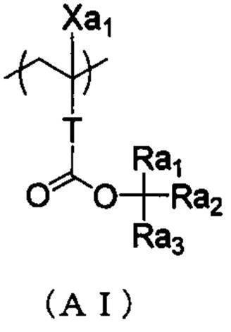
Xa1は、水素原子、又は置換基を有していてもよいアルキル基を表す。
Tは、単結合又は2価の連結基を表す。
Ra1~Ra3は、それぞれ独立に、アルキル基(直鎖状又は分岐鎖状)又はシクロアルキル基(単環又は多環)を表す。
Ra1~Ra3の2つが結合して、シクロアルキル基(単環又は多環)を形成してもよい。
Xa1は、水素原子、メチル基、トリフルオロメチル基又はヒドロキシメチル基が好ましい。
Tは、単結合又は-COO-Rt-基が好ましい。Rtは、炭素数1~5のアルキレン基が好ましく、-CH2-基、-(CH2)2-基、又は、-(CH2)3-基がより好ましい。
Ra1~Ra3の2つが結合して形成されるシクロアルキル基としては、シクロペンチル基、若しくはシクロヘキシル基等の単環のシクロアルキル基、又は、ノルボルニル基、テトラシクロデカニル基、テトラシクロドデカニル基、若しくはアダマンチル基等の多環のシクロアルキル基が好ましい。炭素数5~6の単環のシクロアルキル基がより好ましい。
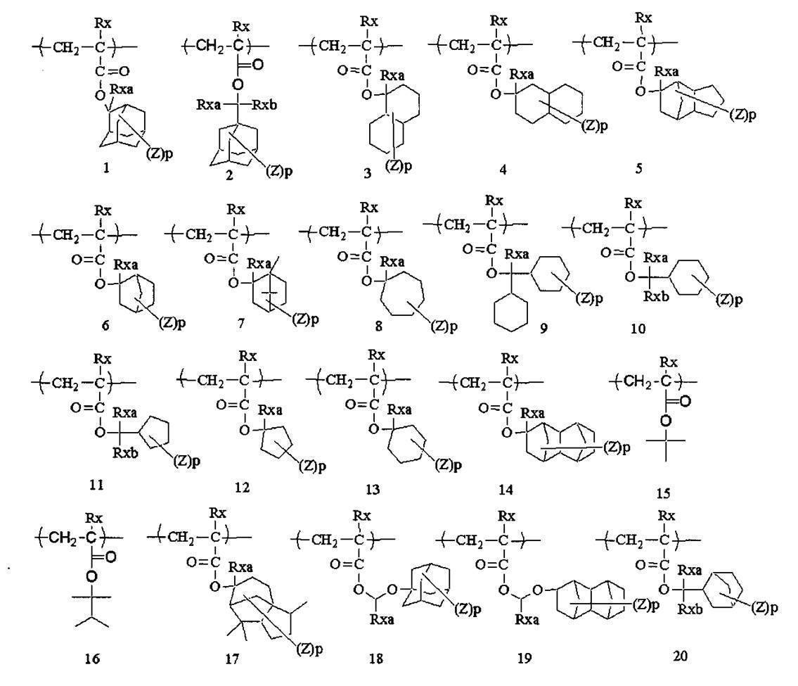
また、樹脂Pは、ラクトン構造を有する繰り返し単位Qを含有することが好ましい。
ラクトン構造を有する繰り返し単位Qは、1種単独で用いてもよく、2種以上を併用していてもよいが、1種単独で用いることが好ましい。
上記樹脂Pの全繰り返し単位に対する、ラクトン構造を有する繰り返し単位Qの含有量は、例えば、3~80モル%が挙げられ、3~60モル%が好ましい。
ラクトン構造としては、下記式(LC1-1)~(LC1-17)のいずれかで表されるラクトン構造を有する繰り返し単位を有することが好ましい。ラクトン構造としては式(LC1-1)、式(LC1-4)、式(LC1-5)、又は式(LC1-8)で表されるラクトン構造が好ましく、式(LC1-4)で表されるラクトン構造がより好ましい。


Rx1~Rx5は、各々独立に、水素原子、又は置換基を有していてもよいアルキル基
を表す。
R1~R4は1価の置換基を表し、p1~p4は、各々独立に0又は正の整数を表す。
Raは、直鎖状又は分岐鎖状のアルキル基を表す。
T1~T5は、単結合又は2価の連結基を表す。
R5は1価の有機基を表す。
a~eは、モル%を表し、各々独立に、0≦a≦100、0≦b≦100、0≦c<100、0≦d<100、0≦e<100の範囲に含まれる数を表す。ただし、a+b+c+d+e=100であり、a+b≠0である。
ただし、式(I)中、繰り返し単位(e)は、繰り返し単位(a)~(d)のいずれとも異なる構造を有する。
式(I)中、T1~T5は、上述した式(AI)中のTと同義であり、その好適態様も同じである。
式(I)中、Raは、直鎖状又は分岐鎖状のアルキル基を表す。例えば、メチル基、エチル基、及びt-ブチル基等が挙げられる。なかでも、炭素数1~4の直鎖状又は分岐鎖状のアルキル基が好ましい。
式(I)中、R1~R4は1価の置換基を表す。R1~R4としては、特に限定されないが、例えば、水酸基、シアノ基、及び、水酸基又はシアノ基等を有する直鎖状若しくは分岐鎖状のアルキル基又はシクロアルキル基が挙げられる。
式(I)中、p1~p4は、各々独立に0又は正の整数を表す。なお、pの上限値は、各繰り返し単位において置換し得る水素原子の数に相当する。
式(I)中、R5は、1価の有機基を表す。R5としては、特に限定されないが、例えば、スルトン構造を有する1価の有機基、及び、ジオキソラン等の環状エーテルを有する1価の有機基が挙げられる。
また、樹脂Pは、フェノール性水酸基を有する繰り返し単位を含有していてもよい。
フェノール性水酸基を有する繰り返し単位としては、例えば、下記一般式(I)で表される繰り返し単位が挙げられる。
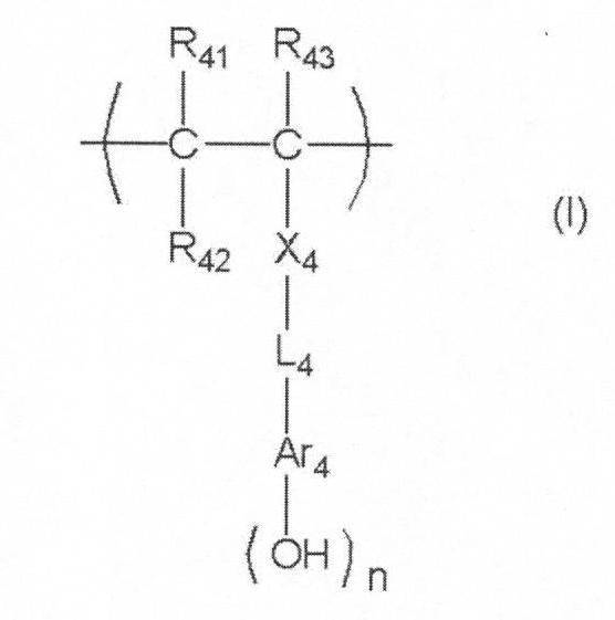
R41、R42及びR43は、各々独立に、水素原子、アルキル基、ハロゲン原子、シアノ基又はアルコキシカルボニル基を表す。但し、R42はAr4と結合して環を形成していてもよく、その場合のR42は単結合又はアルキレン基を表す。
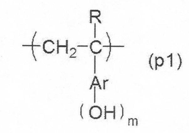


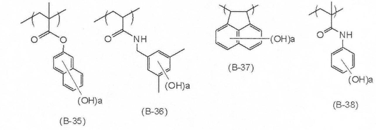
樹脂Pは、極性基を有する有機基を含有する繰り返し単位、特に、極性基で置換された脂環炭化水素構造を有する繰り返し単位を更に含有していてもよい。
これにより基板密着性、現像液親和性が向上する。極性基で置換された脂環炭化水素構造の脂環炭化水素構造としてはアダマンチル基、ジアマンチル基又はノルボルナン基が好ましい。極性基としては、水酸基又はシアノ基が好ましい。
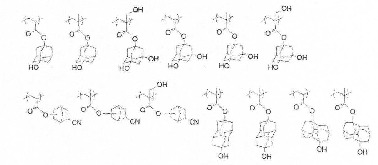
樹脂Pは、活性光線又は放射線の照射により酸を発生する基(光酸発生基)を有する繰り返し単位を含有していてもよい。
活性光線又は放射線の照射により酸を発生する基(光酸発生基)を有する繰り返し単位としては、例えば、下記一般式(4)で表される繰り返し単位が挙げられる。
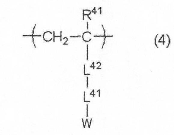
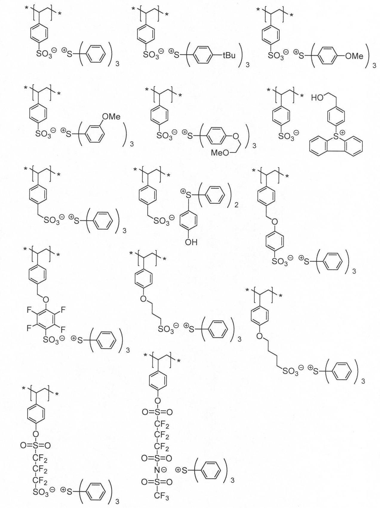
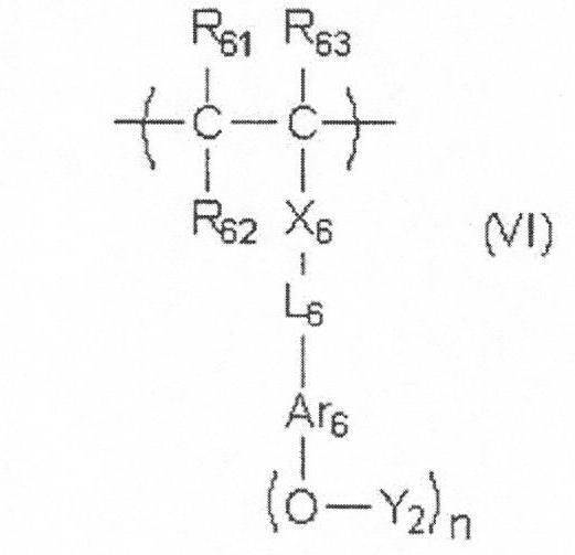
R61、R62及びR63は、各々独立に、水素原子、アルキル基、シクロアルキル基、ハロゲン原子、シアノ基、又はアルコキシカルボニル基を表す。但し、R62はAr6と結合して環を形成していてもよく、その場合のR62は単結合又はアルキレン基を表す。
X6は、単結合、-COO-、又は-CONR64-を表す。R64は、水素原子又はアルキル基を表す。
L6は、単結合又はアルキレン基を表す。
Ar6は、(n+1)価の芳香環基を表し、R62と結合して環を形成する場合には(n+2)価の芳香環基を表す。
Y2は、n≧2の場合には各々独立に、水素原子又は酸の作用により脱離する基を表す。但し、Y2の少なくとも1つは、酸の作用により脱離する基を表す。
nは、1~4の整数を表す。


Ar3は、芳香環基を表す。
R3は、水素原子、アルキル基、シクロアルキル基、アリール基、アラルキル基、アルコキシ基、アシル基又はヘテロ環基を表す。
M3は、単結合又は2価の連結基を表す。
Q3は、アルキル基、シクロアルキル基、アリール基又はヘテロ環基を表す。
Q3、M3及びR3の少なくとも二つが結合して環を形成してもよい。


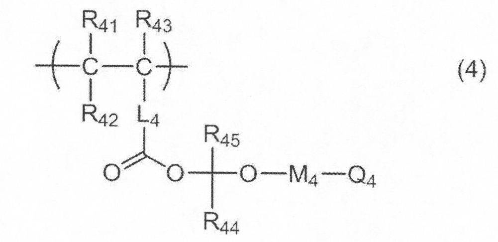
R41、R42及びR43は、各々独立に、水素原子、アルキル基、シクロアルキル基、ハロゲン原子、シアノ基又はアルコキシカルボニル基を表す。R42はL4と結合して環を形成していてもよく、その場合のR42はアルキレン基を表す。
L4は、単結合又は2価の連結基を表し、R42と環を形成する場合には3価の連結基を表す。
R44及びR45は、水素原子、アルキル基、シクロアルキル基、アリール基、アラルキル基、アルコキシ基、アシル基又はヘテロ環基を表す。
M4は、単結合又は2価の連結基を表す。
Q4は、アルキル基、シクロアルキル基、アリール基又はヘテロ環基を表す。
Q4、M4及びR44の少なくとも二つが結合して環を形成してもよい。
L4は、前述の一般式(V)中のL5と同義であり、また好ましい範囲も同様である。
R44及びR45は、前述の一般式(3)中のR3と同義であり、また好ましい範囲も同様である。
M4は、前述の一般式(3)中のM3と同義であり、また好ましい範囲も同様である。
Q4は、前述の一般式(3)中のQ3と同義であり、また好ましい範囲も同様である。

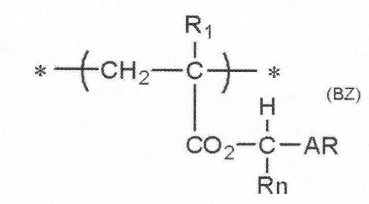
R1は、水素原子、アルキル基、シクロアルキル基、ハロゲン原子、シアノ基又はアルキルオキシカルボニル基を表す。

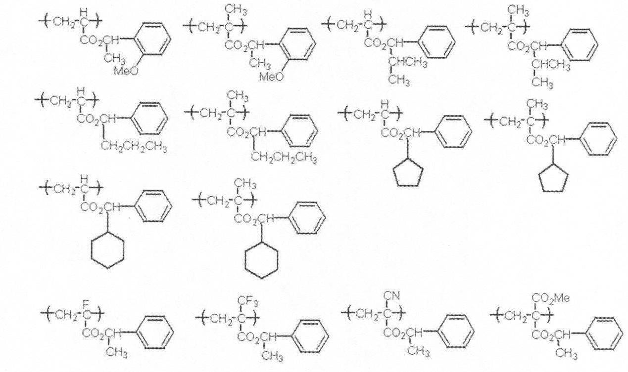

R6及びR7は、それぞれ独立に、水素原子、ヒドロキシ基、炭素数1~10の直鎖状、分岐状又は環状のアルキル基、アルコキシ基又はアシロキシ基、シアノ基、ニトロ基、アミノ基、ハロゲン原子、エステル基(-OCOR又は-COOR:Rは炭素数1~6のアルキル基又はフッ素化アルキル基)、又はカルボキシル基を表す。
n3は0~6の整数を表す。
n4は0~4の整数を表す。
X4はメチレン基、酸素原子又は硫黄原子である

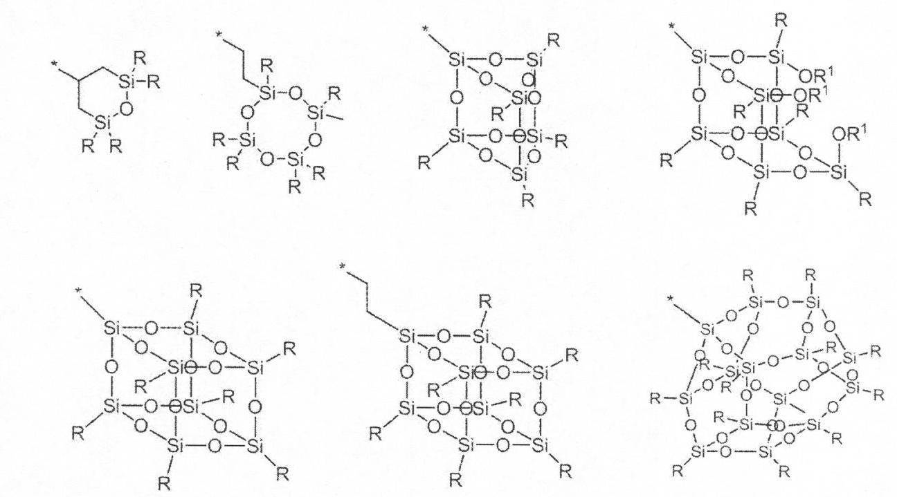
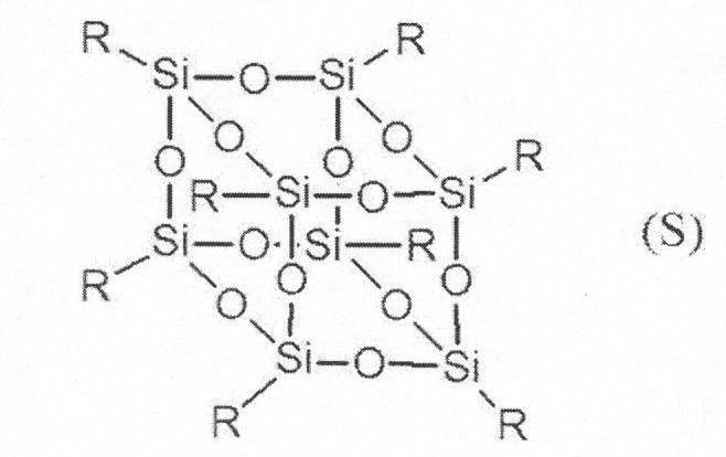
また、感活性光線性又は感放射線性組成物において、樹脂Pは、1種で使用してもよいし、複数併用してもよい。
本発明のパターン形成方法は、パターン形成において一般的に実施される工程である、(i)プリウェット液を基板に接触させるプリウェット工程、(ii)基板上にレジスト膜を形成するレジスト膜形成工程、及び(iii)露光されたレジスト膜を、現像液を用いて現像する現像工程、のいずれか1つ以上の工程において本発明の溶液を使用する。
以下に本発明のパターン形成方法の一例として、第1実施形態~第3実施形態を示す。
パターン形成方法の第1の実施形態は、
プリウェット液を基板に接触させるプリウェット工程と、
感活性光線性又は感放射線性樹脂組成物を用いて、上記基板上にレジスト膜を形成するレジスト膜形成工程と、
レジスト膜を露光する露光工程と、
露光された上記レジスト膜を、現像液を用いて現像する現像工程と、を有するパターン形成方法であって、
本発明の溶液を上記プリウェット液として用いる。
パターン形成方法の第2の実施形態は、
感活性光線性又は感放射線性樹脂組成物を用いて、基板上にレジスト膜を形成するレジスト膜形成工程と、
レジスト膜を露光する露光工程と、
露光された上記レジスト膜を、現像液を用いて現像する現像工程と、を有するパターン形成方法であって、
上記感活性光線性又は感放射線性樹脂組成物が、本発明の溶液を含有する。
パターン形成方法の第3の実施形態は、
感活性光線性又は感放射線性樹脂組成物を用いて、基板上にレジスト膜を形成するレジスト膜形成工程と、
レジスト膜を露光する露光工程と、
露光された上記レジスト膜を、現像液を用いて現像する現像工程と、を有するパターン形成方法であって、
本発明の溶液を上記現像液として用いる。
パターン形成方法の第4の実施形態は、
感活性光線性又は感放射線性樹脂組成物を用いて、基板上にレジスト膜を形成するレジスト膜形成工程と、
レジスト膜を露光する露光工程と、
露光された上記レジスト膜を、現像液を用いて現像する現像工程と、
形成されたパターンを、リンス液を用いてリンスするリンス工程と、
を有するパターン形成方法であって、
本発明の溶液を上記リンス液として用いる。
上記第1実施形態は、プリウェット液として本発明の溶液を用いる以外は特に限定されず、プリウェット方法については公知のとおりに実施すればよい。
また、上記第2実施形態は、公知の感活性光線性又は感放射線性樹脂組成物において希釈液として用いられる有機溶媒を本発明の溶液とする以外は特に限定されず、その他の材料及びレジスト膜形成の手法については公知のとおりに実施すればよい。
また、上記第3実施形態は、現像液として本発明の溶液を用いる以外は特に限定されず、現像方法については公知のとおりに実施すればよい。
また、上記第4実施形態は、リンス液として本発明の溶液を用いる以外は特に限定されず、リンス方法については公知のとおりに実施すればよい。
また、本発明は、上記した本発明のパターン形成方法を含む、半導体デバイスの製造方法にも関する。本発明の半導体デバイスの製造方法により製造された半導体デバイスは、電気電子機器(例えば、家電、OA(Office Automation)関連機器、メディア関連機器、光学用機器、及び、通信機器等)に、好適に搭載されるものである。
〔溶液の調製〕
実施例及び比較例の溶液は、表1に示す沸点が200℃未満の有機溶媒と、沸点が250℃以上の有機化合物と、を混合した混合液に対して下記の精製工程を実施することにより、各々調製した。
なお、表1に挙げる沸点が250℃以上の有機化合物は、溶媒調製時において製造装置等の部材(例えば、Oリング)からの溶出が実際に確認された有機化合物に相当する。つまり、本実施例及び比較例においては、沸点が200℃未満の有機溶媒と、沸点が250℃以上の有機不純物としての上記沸点が250℃以上の有機化合物と、を含有するモデル溶液を各々調製し、その評価を実施した。
ここで、表1に示す沸点が200℃未満の有機溶媒及び沸点が250℃以上の有機化合物には、半導体グレードに分類されるもの、又は、それに準ずる高純度グレードに分類されるものを用いた。
(1)脱水を行う脱水処理(過熱による揮発除去)
(2)脱水処理後の被精製液の蒸留を行う蒸留処理
(3)Entegris社製 15nmIEX(ion-exchange) PTFEフィルタを用いて被精製液のイオン交換処理を行う第1イオン交換処理
(4)Entegris社製 12nm PTFEフィルタを用いて、蒸留処理後の被精製液のイオン交換処理を行う第2イオン交換処理
(5)孔径が20nm以下の精密濾過膜を用いて粒子を除去する粒子除去処理
nBA: 酢酸ブチル(沸点 126℃)
PGME: プロピレングリコールモノメチルエーテル(沸点 121℃)
PGEE: プロピレングリコールモノエチルエーテル(沸点 133℃)
PGPE: プロピレングリコールモノプロピルエーテル(沸点 149℃)
EL: 乳酸エチル(沸点 155℃)
CyPe: シクロペンタノン(沸点 130℃)
CyHe: シクロヘキサノン(沸点 155℃)
PGMEA:プロピレングリコールモノメチルエーテルアセタート(沸点 146℃)
MIBC: 4-メチル-2-ペンタノール(沸点 132℃)
DOP: フタル酸ジオクチル(沸点 385℃、炭素数 24)
DINP: フタル酸ジイソノニル(沸点 403℃、炭素数 26)
DOA: アジピン酸ジオクチル(沸点 335℃、炭素数 22)
DBP: フタル酸ジブチル(沸点 340℃、炭素数 16)
EPDM: エチレンプロピレンゴム(沸点300~450℃、炭素数>12)
フタル酸ジメチル(沸点 283℃、炭素数 10)
p-トルイル酸(沸点 275℃、炭素数 8)
DEHP: フタル酸ビス(2-エチルヘキシル)(沸点 385℃、炭素数 24)
ENB:5-エチリデン-2-ノルボルネンの付加重合体(下記構造式:沸点>250℃、炭素数>50)

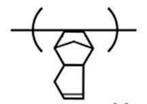
HD:1,4-ヘキサジエンの付加重合体(下記構造式:沸点>250℃、炭素数>50)
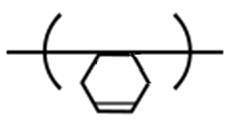
DPHP:フタル酸ビス(2-プロピルヘプチル)(沸点 361℃、炭素数 28)
BBzP:フタル酸ベンジルブチル(沸点 340℃、炭素数 16)
DIOP:フタル酸ジイソオクチル(沸点 385℃、炭素数 24)
DEP:フタル酸ジエチル(沸点 302℃、炭素数 12)
DIBP:フタル酸ジイソブチル(沸点 320℃、炭素数 16)
TEHTM:トリメリット酸トリス(2-エチルヘキシル)(沸点 414℃、炭素数 33)
ATM:トリメリット酸トリス(n-オクチル-n-デシル)(沸点 455℃、炭素数 72)
DEHA:アジピン酸ビス(2-エチルヘキシル)(沸点 335℃、炭素数 22)
MMAD:アジピン酸モノメチル(沸点 265℃、炭素数 7)
DBS:セバシン酸ジブチル(沸点 345℃、炭素数 18)
DBM:マレイン酸ジブチル(沸点 281℃、炭素数 12)
DIBM:マレイン酸ジブチル(沸点 296℃、炭素数 12)
DEHT:ジオクチルテレフタレート(沸点 385℃、炭素数 24)
DINCH:1,2-シクロヘキサンジカルボン酸ジイソノニルエステル(沸点 395℃、炭素数 26)
エポキシ化植物油:沸点>400℃、炭素数>50
HP BSA:N-(2-ヒドロキシプロピル)ベンゼンスルホンアミド(沸点 279℃、炭素数 9)
BBSA-NBBS:N-(n-ブチル)ベンゼンスルホンアミド(沸点 306℃、炭素数 10)
TCP:リン酸トリクレジル(沸点 312℃、炭素数 21)
TBP:リン酸トリブチル(沸点 289℃、炭素数 12)
TEC:クエン酸トリエチル(沸点 294℃、炭素数 12)
ATEC:アセチルクエン酸トリエチル(沸点 300℃、炭素数 14)
TBC:クエン酸トリブチル(沸点 302℃、炭素数 18)
ATBC:アセチルクエン酸トリブチル(沸点 305℃、炭素数 20)
TOC:クエン酸トリオクチル(沸点 320℃、炭素数 30)
ATOC:アセチルクエン酸トリオクチル(沸点 335℃、炭素数 32)
THC:クエン酸トリへキシル(沸点 310℃、炭素数 24)
ATHC:アセチルクエン酸トリへキシル(沸点 305℃、炭素数 26)
ESBO:エポキシ化大豆油(沸点 256℃、炭素数60)
(沸点が250℃以上の有機不純物の含有量の測定)
実施例及び比較例の各溶液を用いて、溶液中の沸点が250℃以上の有機不純物の含有量(溶液全質量に対する含有量)を測定した。測定には、GC-MS(製品名「GCMS-2020」、島津製作所社製)を用いて測定し、面積百分率法により求めた。測定結果を表1に示す。
実施例及び比較例の各溶液を用いて、溶液中の水の含有量(溶液全質量に対する含有量)を測定した。測定には、カールフィッシャー水分計(製品名「MKC-710M」、京都電子工業社製、カールフィッシャー電量滴定式)を用いた。測定結果を表1に示す。
実施例及び比較例の溶液を用いて、溶液中の金属成分(金属不純物)の含有量(溶液全質量に対する含有量)を測定した。具体的には、実施例及び比較例の各溶液を用いて、NexION350S(商品名、PerkinElmer社製)を用いて、ICP-MS法により行った。測定結果を表1に示す。
ICP-MS法による具体的な測定条件は、次の通りである。
なお、濃度既知の標準液に対するピーク強度にて検出量を測定して、金属元素の質量に換算し、測定に使用した溶液中の各金属元素の含有量を算出した。
(ICP-MS法による測定条件)
((標準物質))
清浄なガラス容器内へ超純水を計量投入し、メディアン径50nmの測定対象金属粒子を1質量pptの濃度となるように添加した後、超音波洗浄機で30分間処理した分散液を輸送効率測定用の標準物質として用いた。
((使用したICP-MS装置))
メーカー:PerkinElmer
型式:NexION350S
((ICP-MSの測定条件))
ICP-MSはPFA製同軸型ネブライザ(なお、「PFA」とは、テトラフルオロエチレンとパーフルオロアルキルビニルエーテルの共重合体である。)、石英製サイクロン型スプレーチャンバ、石英製内径1mmトーチインジェクタを用い、測定対象液を約0.2mL/分で吸引した。酸素添加量は0.1L/分、プラズマ出力1600W、アンモニアガスによるセルパージを行った。時間分解能は50μsにて解析を行った。
((ソフトウェア))
金属元素の含有量は、メーカー付属の下記解析ソフトを用いて計測した。
Syngistix for ICP-MS ソフトウェア
実施例及び比較例の各溶液を用いて、溶液中の粗大粒子数を測定した。
なお、上述の溶液については、調製後1日室温で静置した後に、動的光散乱法に基づく、光散乱式液中粒子計数器(リオン株式会社製、型番:KS-18F、光源:半導体レーザ励起固体レーザ(波長532nm、定格出力500mW)、流量:10mL/分)を用いて、1mL中に含まれる0.1μm以上のサイズの被計数体の計数を5回行い、その平均値を計測値とした。
なお、上記光散乱式液中粒子計数器は、PSL(Polystyrene Latex)標準粒子液で校正を行った後に用いた。
ウエハ上表面検査装置(SP-5;KLA Tencor製)により、直径300mmのシリコン酸化膜基板表面に存在する直径32nm以上のパーティクル(以下、これを「欠陥」という。)数を計測した。次いで、このシリコン酸化膜基板をスピン吐出装置にセットし、回転させながら、同シリコン酸化膜基板の表面へ、実施例又は比較例の各溶液を1.5L/分の流速で吐出した。その後、ウエハのスピン乾燥を行った。
得られた乾燥後のウエハについて、再び上記装置(SP-5)を用いてシリコン酸化膜基板表面に存在する欠陥数の計測を行い、初期値との差分(初期値-計測値)を欠陥数とした。
得られた欠陥数を下記基準に基づき評価した結果を表1に示す。下記基準において、評価が「C」以上であれば、半導体デバイス製造用の溶液として要求される欠陥抑制能を達成している。
「A」:欠陥数が500以下
「B」:欠陥数が500超1000以下
「C」:欠陥数が1000超1500個以下
「D」:欠陥数が1500超
特に、今回使用したSP-5は、ベアウェハの欠陥検出の装置であり、ランダム欠陥の検出に有効である。その測定原理は、回転しているウェハにレーザー光線を当て、半径方向に(相対)移動することによって、ウェハ上全面にレーザービームを照射する。この際に、ウェハが回転して、異物及び欠陥にレーザー光線が当たると、光が散乱し、散乱光が検出器で検出される。これによって、異物及び欠陥が検出される。ウェハの回転角度と、レーザー光線の半径位置から、異物及び欠陥の座標位置を割り出して登録される。
特に、10nmノード以下の微細な半導体装置の製造に係る欠陥の評価には、SP-5の分解能以上のウェハ上表面検査装置を用いることが好ましい
また、実施例21の「沸点が200℃未満の有機溶媒」欄に記載される組成比は、質量比を意味する。

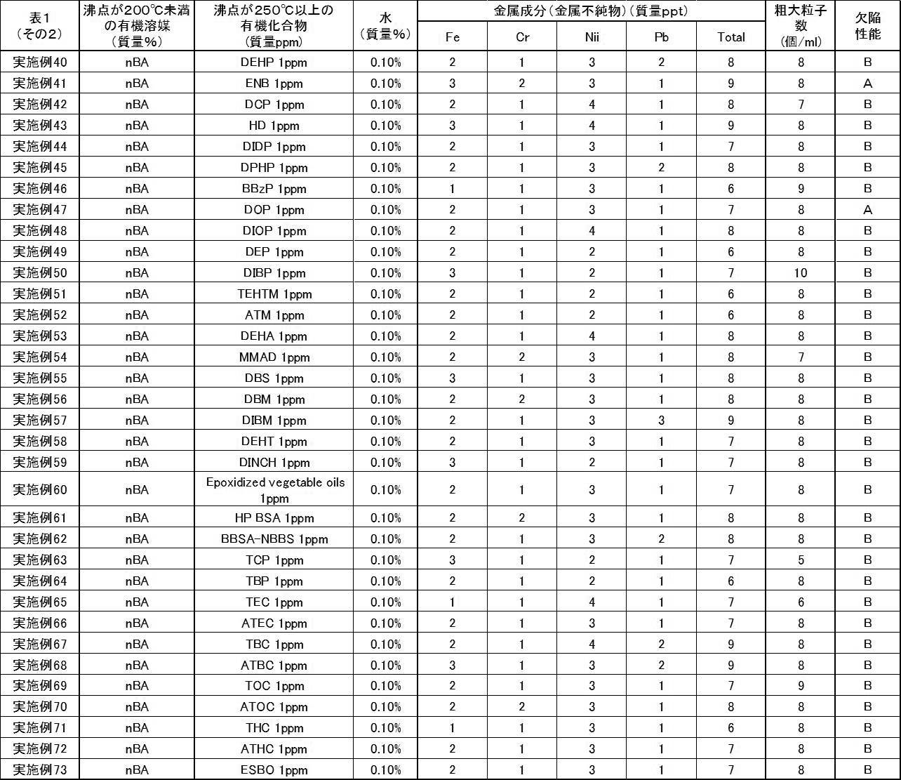
また、沸点が250℃以上の有機化合物(沸点が250℃以上の有機不純物)の含有量が、溶液全質量に対して0.1~8質量ppmである場合、欠陥抑制能により優れることが確認された。
下記に示すフォトレジスト組成物を用い、表2に示すようにパターン形成を実施した。
感活性光線性又は感放射線性樹脂組成物しては下記のものを用いた。なお、感活性光線性又は感放射線性樹脂組成物については、各成分を混合した後、0.03μmのポアサイズを有するポリエチレンフィルターでろ過して調製した。
酸分解性樹脂(下記式で表される樹脂(重量平均分子量(Mw) 7500):各繰り返し単位に記載される数値はモル%を意味する。):100質量部
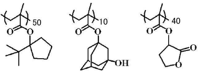
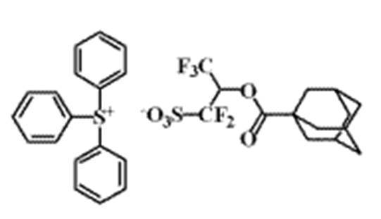

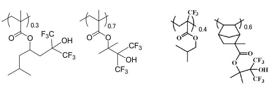
PGMEA(プロピレングリコールモノメチルエーテルアセテート):3質量部
シクロヘキサノン:600質量部
γ-BL(γ-ブチロラクトン):100質量部
酸分解性樹脂(下記式で表される樹脂(重量平均分子量(Mw) 8000):各繰り返し単位に記載される数値はモル%を意味する。):100質量部

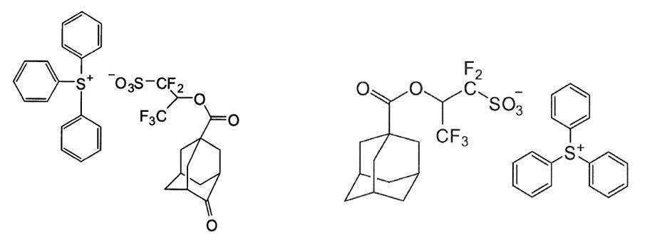
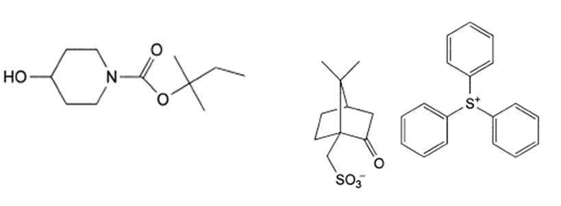


PGMEA(プロピレングリコールモノメチルエーテルアセテート):3質量部
シクロヘキサノン:600質量部
γ-BL(γ-ブチロラクトン):100質量部
酸分解性樹脂(下記式で表される樹脂(重量平均分子量(Mw) 10000):各繰り返し単位に記載される数値はモル%を意味する。):100質量部

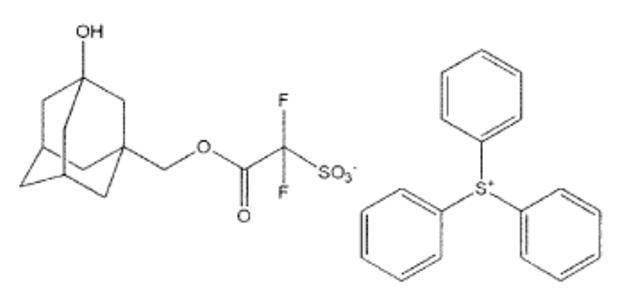


PGMEA(プロピレングリコールモノメチルエーテルアセテート):3質量部
シクロヘキサノン:500質量部
γ-BL(γ-ブチロラクトン):200質量部
<ネガ現像液を使用した(NTIによるパターン現像による)レジスト評価>
(レジストパターンの形成)
以下に示す操作によりレジストパターンを形成した。
シリコンウエハの表面にプリウェット液(下記表2に記載のもの)を滴下し、スピン塗布を実施した。
シリコンウエハ上に有機反射防止膜形成用組成物ARC29SR(日産化学社製)を塗布し、205℃で60秒間ベークを行い、膜厚95nmの反射防止膜を形成した。次いで、得られた反射防止膜上に、調製した感活性光線性又は感放射線性樹脂組成物(下記表2に記載のもの)を塗布し、100℃で、60秒間に亘ってベーク(PB:Prebake)を行い、膜厚90nmのレジスト膜を形成した。
得られたウエハをArFエキシマレーザー液浸スキャナー(ASML社製;XT1700i、NA1.20、Dipole(outerσ:0.981/innerσ:0.895)、Y偏向)を用い、ハーフトーンマスクを介してパターン露光した。液浸液としては超純水を用いた。液浸液としては超純水を用いた。その後、105℃で60秒間加熱(PEB:Post Exposure Bake)した。次いで、ネガ型現像液(下記表2に記載のもの)で30秒間パドルして現像した。続いて、4000rpmの回転数で30秒間ウエハを回転させることにより、ネガ型レジストパターンを形成した。
(欠陥評価)
上記のレジストパターンが形成されたウエハをパターン欠陥装置(例えば、日立ハイテクノロジー社製 マルチパーパスSEM `Inspago` RS6000シリーズ)にて、パターン上の欠陥数を観測した。以下を評価基準としてそれぞれ欠陥抑制能を判断した。
「A」:欠陥数が50以下
「B」:欠陥数が50超100以下
「C」:欠陥数が100超150個以下
「D」:欠陥数が150超

下記に示すレジスト組成物を用い、欠陥の評価試を実施した。
(合成例1)樹脂(A-1)の合成
2Lフラスコにシクロヘキサノン600gを入れ、100mL/minの流量で一時間窒素置換した。その後、重合開始剤V-601(和光純薬工業(株)製)4.60g(0.02mol)を加え、内温が80℃になるまで昇温した。次に、以下のモノマーと重合開始剤V-601(和光純薬工業(株)製)4.60g(0.02mol)とを、シクロヘキサノン200gに溶解し、モノマー溶液を調製した。モノマー溶液を上記80℃に加熱したフラスコ中に6時間かけて滴下した。滴下終了後、更に80℃で2時間反応させた。
4-アセトキシスチレン 48.66g(0.3mol)
1-エチルシクロペンチルメタクリレート 109.4g(0.6mol)
モノマー1 22.2g(0.1mol)
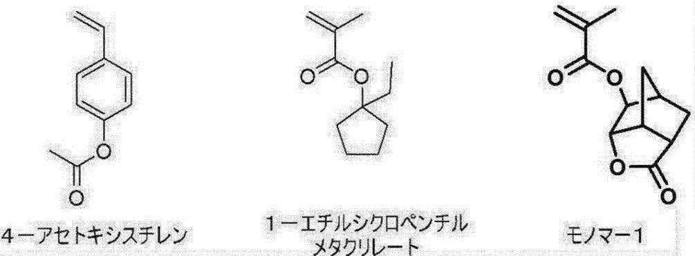
表3において、樹脂の組成比(モル比)は、1H-NMR(核磁気共鳴)測定により算出した。樹脂の重量平均分子量(Mw:ポリスチレン換算)、分散度(Mw/Mn)はGPC(溶媒:THF)測定により算出した。なお、実施例中に示す他の樹脂についても同様の方法により、重量平均分子量、分散度を測定した。
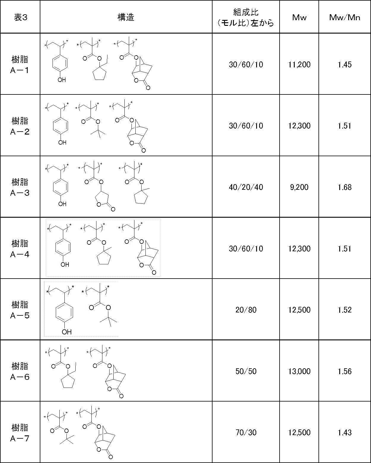
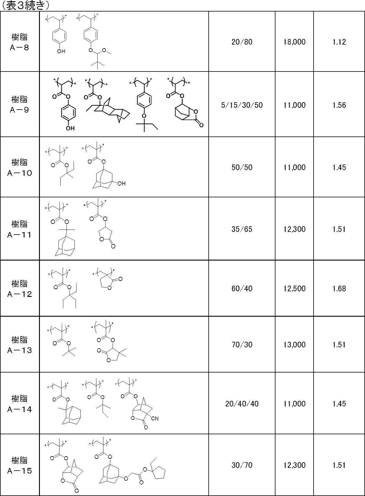

疎水性樹脂としては、以下のものを用いた。

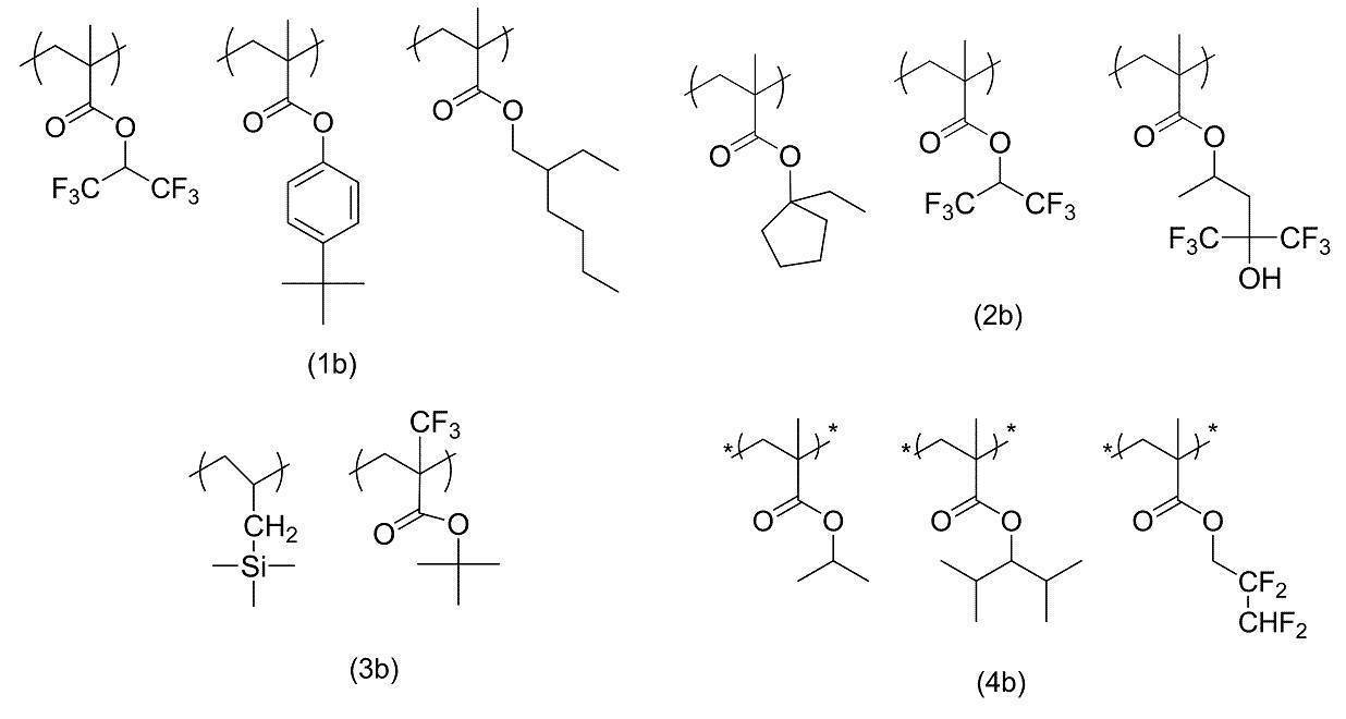

光酸発生剤としては、以下のものを用いた。
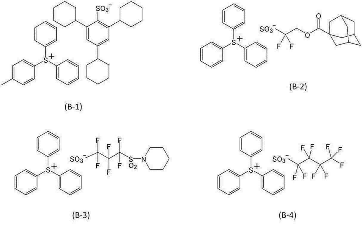
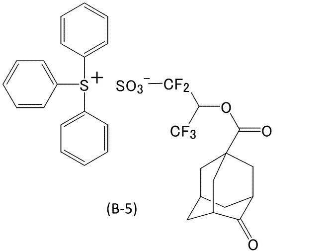

塩基性化合物としては、以下のものを用いた。

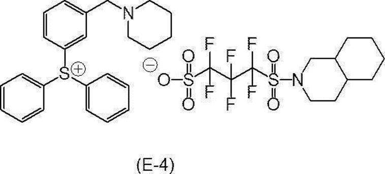
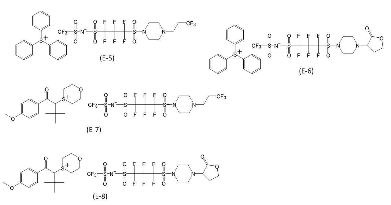
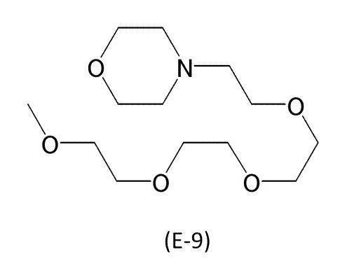
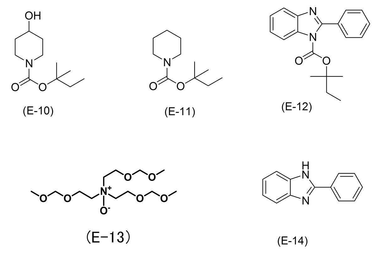
レジスト溶剤としては、以下のものを用いた。
C-1:プロピレングリコールモノメチルエーテルアセテート
C-2:プロピレングリコールモノメチルエーテル
C-3:乳酸エチル
C-4:シクロヘキサノン
下記表5に示す各成分を、同表に示す溶剤に溶解させた。これを0.03μmのポアサイズを有するポリエチレンフィルターを用いてろ過して、レジスト組成物を得た。
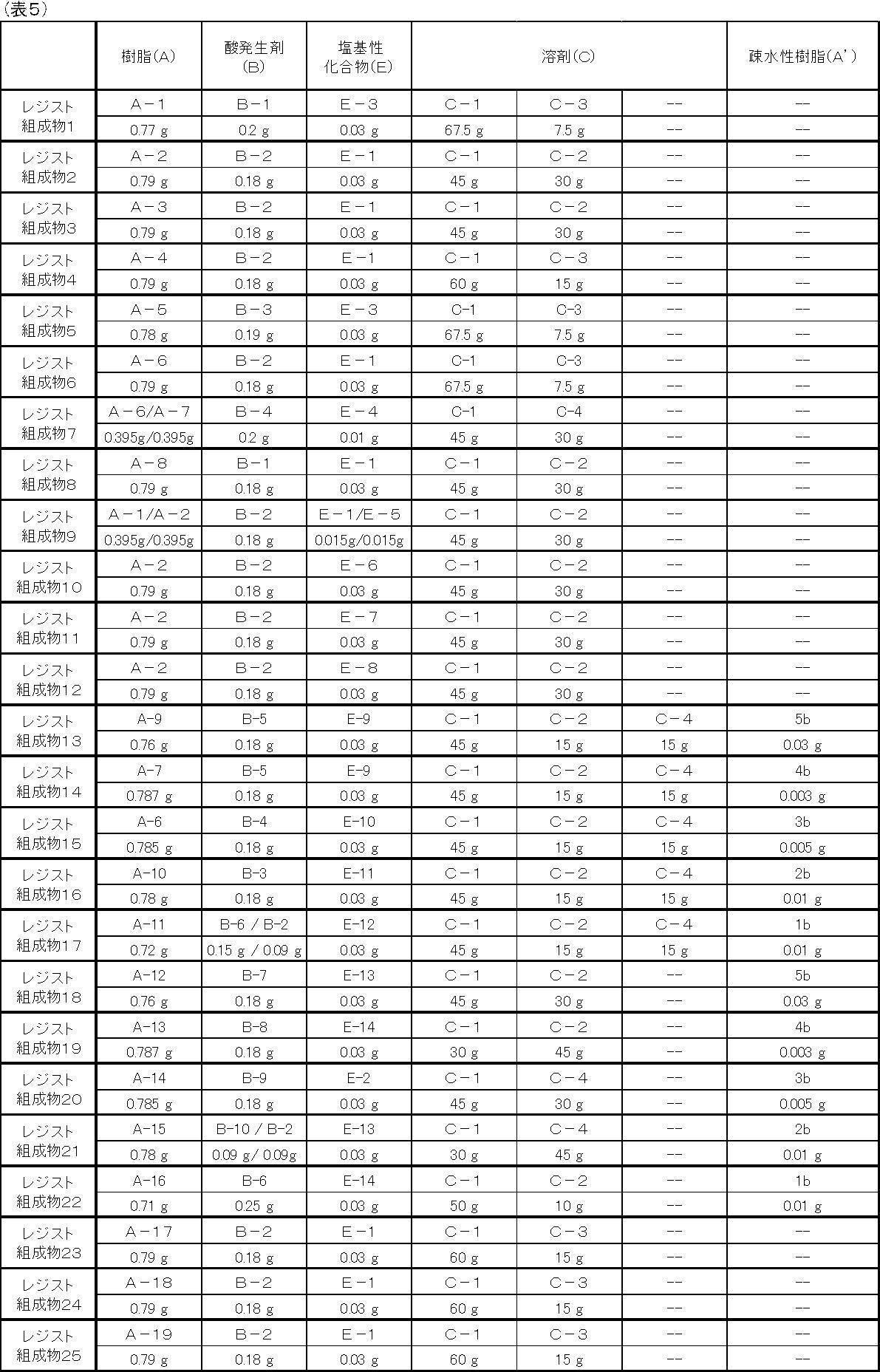
<ネガ現像液を使用した(NTIによるパターン現像による)レジスト評価>
(レジストパターンの形成)
以下に示す操作によりレジストパターンを形成した。
シリコンウエハの表面にプリウェット液(下記表6に記載のもの)を滴下し、スピン塗布を実施した。
12インチシリコンウエハ上に、上記のようにして得られた各レジスト組成物を塗布し、90~180℃の条件で60秒間ベークし、膜厚40nmのレジスト膜を形成した。
上記で作製したウエハに、NA(レンズ開口数、Numerical Aperture)0.25、ダイポール照明(Dipole 60x、アウターシグマ0.81、インナーシグマ0.43)でEUV露光を行った。具体的には、ネガ型のレジストに対しては1mJ/cm2の露光量にてハーフトーンマスクを介してパターン露光した。
照射後、EUV露光装置から取り出したら、ただちに、85~130℃の条件で60秒間ベークした。
その後、シャワー型現像装置(ACTES(株)製ADE3000S)を用いて、50回転(rpm)でウエハを回転しながら、現像液(23℃)を、200mL/分の流量で30秒間スプレー吐出することで、現像を行った。なお、現像液としては、ネガ型現像液(下記表6に記載のもの)を用いた。
(欠陥評価)
上記のレジストパターンが形成されたウエハをパターン欠陥装置(例えば、日立ハイテクノロジー社製 マルチパーパスSEM `Inspago` RS6000シリーズ)にて、パターン上の欠陥数を観測した。以下を評価基準としてそれぞれ欠陥抑制能を判断した。
「A」:欠陥数が50以下
「B」:欠陥数が50超100以下
「C」:欠陥数が100超150個以下
「D」:欠陥数が150超
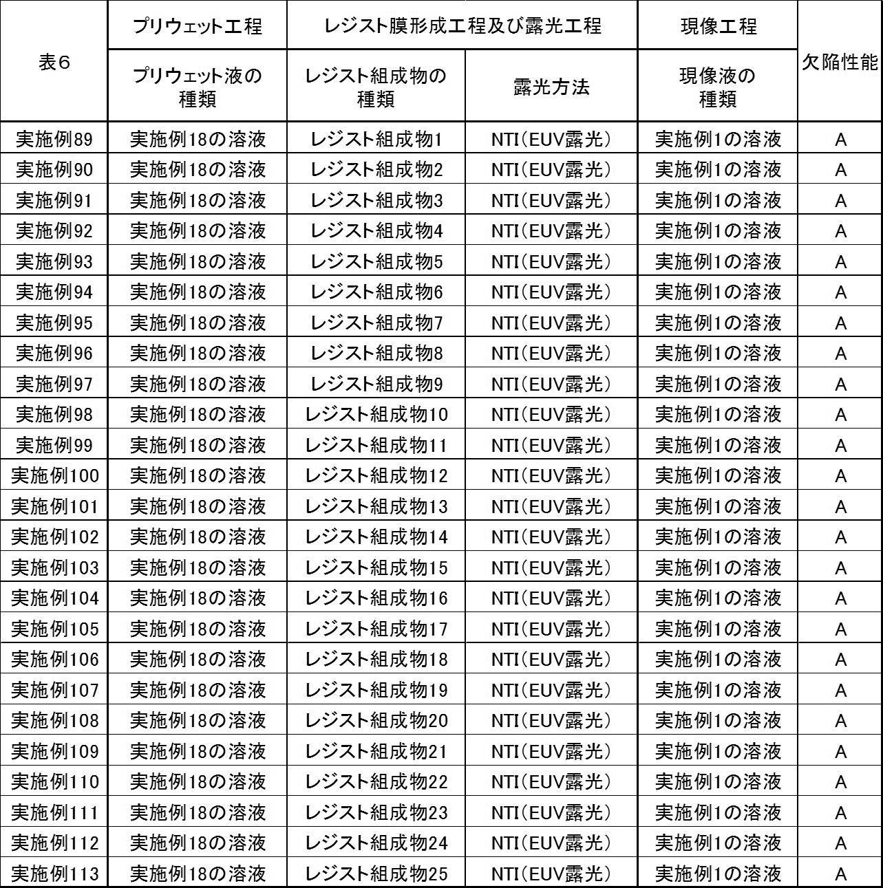
Claims (32)
- 沸点が200℃未満の有機溶媒を少なくとも1種と、沸点が250℃以上の有機不純物と、を含有する溶液であり、
前記有機溶媒の含有量が、溶液全質量に対して98質量%以上であり、
前記有機不純物の含有量が、溶液全質量に対して0.1質量ppm以上100質量ppm未満である、溶液。 - Fe、Cr、Ni及びPbからなる群から選ばれる元素を含有する金属成分の含有量が、溶液全質量に対して0.001~10質量pptである、請求項1に記載の溶液。
- Fe、Cr、Ni及びPbからなる群から選ばれる元素を含有する金属成分の含有量が、溶液全質量に対して0.1~10質量pptである、請求項2に記載の溶液。
- 光散乱式液中粒子計数器によって計数される、0.1μm以上のサイズの被計数体の数が、100個/mL以下である、請求項1~3のいずれか1項に記載の溶液。
- 水の含有量が、溶液全質量に対して0.01~1.0質量%である、請求項1~4のいずれか1項に記載の溶液。
- 前記有機不純物が、炭素数8以上の有機化合物である、請求項1~5のいずれか1項に記載の溶液。
- 前記有機不純物が、炭素数12以上の有機化合物である、請求項1~6のいずれか1項に記載の溶液。
- 前記有機不純物が、沸点が270℃以上の有機不純物を含み、
前記沸点が270℃以上の有機不純物の含有量が、溶液全質量に対して0.01~60質量ppmである、請求項1~7のいずれか1項に記載の溶液。 - 前記有機不純物が、沸点が300℃以上の有機不純物を含み、
前記沸点が300℃以上の有機不純物の含有量が、溶液全質量に対して0.01~30質量ppmである、請求項1~8のいずれか1項に記載の溶液。 - 前記有機不純物が、沸点が300℃以上の有機不純物を含み、
前記沸点が300℃以上の有機不純物の含有量が、溶液全質量に対して0.1~30質量ppmである、請求項9に記載の溶液。 - 前記有機不純物が、フタル酸ジオクチル、フタル酸ジイソノニル、アジピン酸ジオクチル、フタル酸ジブチル、エチレンプロピレンゴム、及び5-エチリデン-2-ノルボルネンの付加重合体からなる群より選ばれる1種以上である、請求項1~10のいずれか1項に記載の溶液。
- 半導体デバイス製造プロセスにおいて、プリウェット液、現像液、及び感活性光線性又は感放射線性樹脂組成物に含まれる溶剤から選択される少なくとも1つの用途に用いられる、請求項1~11のいずれか1項に記載の溶液。
- 前記有機溶媒が、プロピレングリコールモノメチルエーテル、プロピレングリコールモノエチルエーテル、プロピレングリコールモノプロピルエーテル、プロピレングリコールモノメチルエーテルアセテート、乳酸エチル、メトキシプロピオン酸メチル、シクロペンタノン、シクロヘキサノン、ジイソアミルエーテル、酢酸ブチル、酢酸イソアミル、及び、4-メチル-2-ペンタノールからなる群より選ばれる少なくとも1種である、請求項1~12のいずれか1項に記載の溶液。
- 半導体デバイス製造プロセスにおいて、下記式(AI)で表される繰り返し単位を有する樹脂Pを含有する感活性光線性又は感放射線性樹脂組成物から形成されるレジスト膜に対するプリウェット液又は現像液の用途に用いられる、請求項1~13のいずれか1項に記載の溶液。

式(AI)中、
Xa1は、水素原子、又は置換基を有していてもよいアルキル基を表す。
Tは、単結合又は2価の連結基を表す。
Ra1~Ra3は、それぞれ独立に、アルキル基又はシクロアルキル基を表す。
Ra1~Ra3の2つが結合して、シクロアルキル基を形成してもよい。 - 前記樹脂Pが、更に、側鎖にラクトン構造を有する繰り返し単位Qを有する、請求項14に記載の溶液。
- 前記樹脂Pが、下記式(I)で表される樹脂である、請求項14に記載の溶液。

上記式(I)中、
Rx1~Rx5は、各々独立に、水素原子、又は置換基を有していてもよいアルキル基を表す。
R1~R4は1価の置換基を表し、p1~p4は、各々独立に0又は正の整数を表す。
Raは、直鎖状又は分岐鎖状のアルキル基を表す。
T1~T5は、単結合又は2価の連結基を表す。
R5は1価の有機基を表す。
a~eは、モル%を表し、各々独立に、0≦a≦100、0≦b≦100、0≦c<100、0≦d<100、0≦e<100の範囲に含まれる数を表す。ただし、a+b+c+d+e=100であり、a+b≠0である。
ただし、式(I)中、繰り返し単位(e)は、繰り返し単位(a)~(d)のいずれとも異なる構造を有する。 - 半導体デバイス製造プロセスにおいて、フェノール性水酸基を有する繰り返し単位を有し、酸の作用により分解して極性基を生じる基を有する樹脂Pを含有する感活性光線性又は感放射線性樹脂組成物から形成されるレジスト膜に対するプリウェット液又は現像液の用途に用いられる、請求項1~13のいずれか1項に記載の溶液。
- 容器と、前記容器内に収容された請求項1~17のいずれか1項に記載の溶液と、を備えた溶液収容体。
- 前記容器内の前記溶液と接触する接液部が非金属材料又はステンレス鋼により形成された、請求項18に記載の溶液収容体。
- 前記非金属材料が、ポリエチレン樹脂、ポリプロピレン樹脂、ポリエチレン-ポリプロピレン樹脂、四フッ化エチレン樹脂、四フッ化エチレン-パーフルオロアルキルビニルエーテル共重合体、四フッ化エチレン-六フッ化プロピレン共重合樹脂、四フッ化エチレン-エチレン共重合体樹脂、三フッ化塩化エチレン-エチレン共重合樹脂、フッ化ビニリデン樹脂、三フッ化塩化エチレン共重合樹脂、及びフッ化ビニル樹脂からなる群より選ばれる少なくとも1種である、請求項19に記載の溶液収容体。
- 請求項1~11のいずれか1項に記載の溶液と、下記式(AI)で表される繰り返し単位を有する樹脂Pと、を含有する、感活性光線性又は感放射線性樹脂組成物。

式(AI)中、
Xa1は、水素原子、又は置換基を有していてもよいアルキル基を表す。
Tは、単結合又は2価の連結基を表す。
Ra1~Ra3は、それぞれ独立に、アルキル基又はシクロアルキル基を表す。
Ra1~Ra3の2つが結合して、シクロアルキル基を形成してもよい。 - 前記樹脂Pが、更に、側鎖にラクトン構造を有する繰り返し単位Qを有する、請求項21に記載の感活性光線性又は感放射線性樹脂組成物。
- 前記樹脂Pが、式(I)で表される樹脂である、請求項21に記載の感活性光線性又は感放射線性樹脂組成物。
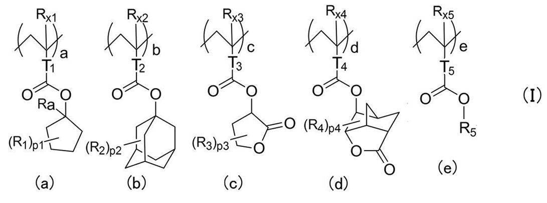
上記式(I)中、
Rx1~Rx5は、各々独立に、水素原子、又は置換基を有していてもよいアルキル基を表す。
R1~R4は1価の置換基を表し、p1~p4は、各々独立に0又は正の整数を表す。
Raは、直鎖状又は分岐鎖状のアルキル基を表す。
T1~T5は、単結合又は2価の連結基を表す。
R5は1価の有機基を表す。
a~eは、モル%を表し、各々独立に、0≦a≦100、0≦b≦100、0≦c<100、0≦d<100、0≦e<100の範囲に含まれる数を表す。ただし、a+b+c+d+e=100であり、a+b≠0である。
ただし、式(I)中、繰り返し単位(e)は、繰り返し単位(a)~(d)のいずれとも異なる構造を有する。 - 請求項1~11のいずれか1項に記載の溶液と、フェノール性水酸基を有する繰り返し単位を有し、酸の作用により分解して極性基を生じる基を有する樹脂Pと、を含有する、感活性光線性又は感放射線性樹脂組成物。
- 感活性光線性又は感放射線性樹脂組成物を用いて、基板上にレジスト膜を形成するレジスト膜形成工程と、
レジスト膜を露光する露光工程と、
露光された前記レジスト膜を、現像液を用いて現像する現像工程と、を有するパターン形成方法であって、
前記感活性光線性又は感放射線性樹脂組成物が、請求項1~11のいずれか1項に記載の溶液を含有する、パターン形成方法。 - プリウェット液を基板に接触させるプリウェット工程と、
感活性光線性又は感放射線性樹脂組成物を用いて、前記基板上にレジスト膜を形成するレジスト膜形成工程と、
レジスト膜を露光する露光工程と、
露光された前記レジスト膜を、現像液を用いて現像する現像工程と、を有するパターン形成方法であって、
請求項1~11のいずれか1項に記載の溶液を前記プリウェット液として用いる、パターン形成方法。 - 感活性光線性又は感放射線性樹脂組成物を用いて、基板上にレジスト膜を形成するレジスト膜形成工程と、
レジスト膜を露光する露光工程と、
露光された前記レジスト膜を、現像液を用いて現像する現像工程と、を有するパターン形成方法であって、
請求項1~11のいずれか1項に記載の溶液を前記現像液として用いる、パターン形成方法。 - 前記感活性光線性又は感放射線性樹脂組成物が、下記式(AI)で表される繰り返し単位を有する樹脂Pを含有する、請求項25~27のいずれか1項に記載のパターン形成方法。
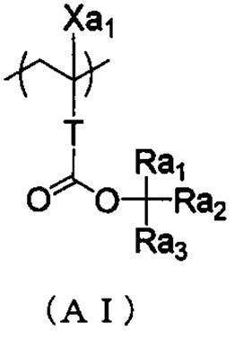
式(AI)中、
Xa1は、水素原子、又は置換基を有していてもよいアルキル基を表す。
Tは、単結合又は2価の連結基を表す。
Ra1~Ra3は、それぞれ独立に、アルキル基又はシクロアルキル基を表す。
Ra1~Ra3の2つが結合して、シクロアルキル基を形成してもよい。 - 前記樹脂Pが、更に、側鎖にラクトン構造を有する繰り返し単位Qを有する、請求項28に記載のパターン形成方法。
- 前記樹脂Pが、下記式(I)で表される樹脂である、請求項28に記載のパターン形成方法。

上記式(I)中、
Rx1~Rx5は、各々独立に、水素原子、又は置換基を有していてもよいアルキル基を表す。
R1~R4は1価の置換基を表し、p1~p4は、各々独立に0又は正の整数を表す。
Raは、直鎖状又は分岐鎖状のアルキル基を表す。
T1~T5は、単結合又は2価の連結基を表す。
R5は1価の有機基を表す。
a~eは、モル%を表し、各々独立に、0≦a≦100、0≦b≦100、0≦c<100、0≦d<100、0≦e<100の範囲に含まれる数を表す。ただし、a+b+c+d+e=100であり、a+b≠0である。
ただし、式(I)中、繰り返し単位(e)は、繰り返し単位(a)~(d)のいずれとも異なる構造を有する。 - 前記感活性光線性又は感放射線性樹脂組成物が、フェノール性水酸基を有する繰り返し単位を有し、酸の作用により分解して極性基を生じる基を有する樹脂Pを含有する、請求項25~27のいずれか1項に記載のパターン形成方法。
- 請求項25~31のいずれか1項に記載のパターン形成方法を含む、半導体デバイスの製造方法。
Priority Applications (5)
| Application Number | Priority Date | Filing Date | Title |
|---|---|---|---|
| JP2018537428A JP6757412B2 (ja) | 2016-09-02 | 2017-09-01 | 溶液、溶液収容体、感活性光線性又は感放射線性樹脂組成物、パターン形成方法、半導体デバイスの製造方法 |
| CN201780053869.4A CN109661615B (zh) | 2016-09-02 | 2017-09-01 | 溶液、溶液收容体、感光化射线性或感放射线性树脂组合物、图案形成方法、半导体装置的制造方法 |
| KR1020197005852A KR102224135B1 (ko) | 2016-09-02 | 2017-09-01 | 용액, 용액 수용체, 감활성 광선성 또는 감방사선성 수지 조성물, 패턴 형성 방법, 반도체 디바이스의 제조 방법 |
| US16/289,813 US11573489B2 (en) | 2016-09-02 | 2019-03-01 | Solution, solution storage body, actinic ray-sensitive or radiation-sensitive resin composition, pattern forming method, and manufacturing method of semiconductor device |
| US18/147,228 US12228857B2 (en) | 2016-09-02 | 2022-12-28 | Solution, solution storage body, actinic ray-sensitive or radiation-sensitive resin composition, pattern forming method, and manufacturing method of semiconductor device |
Applications Claiming Priority (4)
| Application Number | Priority Date | Filing Date | Title |
|---|---|---|---|
| JP2016172239 | 2016-09-02 | ||
| JP2016-172239 | 2016-09-02 | ||
| JP2017-166461 | 2017-08-31 | ||
| JP2017166461 | 2017-08-31 |
Related Child Applications (1)
| Application Number | Title | Priority Date | Filing Date |
|---|---|---|---|
| US16/289,813 Continuation US11573489B2 (en) | 2016-09-02 | 2019-03-01 | Solution, solution storage body, actinic ray-sensitive or radiation-sensitive resin composition, pattern forming method, and manufacturing method of semiconductor device |
Publications (1)
| Publication Number | Publication Date |
|---|---|
| WO2018043695A1 true WO2018043695A1 (ja) | 2018-03-08 |
Family
ID=61300938
Family Applications (1)
| Application Number | Title | Priority Date | Filing Date |
|---|---|---|---|
| PCT/JP2017/031543 Ceased WO2018043695A1 (ja) | 2016-09-02 | 2017-09-01 | 溶液、溶液収容体、感活性光線性又は感放射線性樹脂組成物、パターン形成方法、半導体デバイスの製造方法 |
Country Status (6)
| Country | Link |
|---|---|
| US (2) | US11573489B2 (ja) |
| JP (1) | JP6757412B2 (ja) |
| KR (1) | KR102224135B1 (ja) |
| CN (1) | CN109661615B (ja) |
| TW (1) | TWI742152B (ja) |
| WO (1) | WO2018043695A1 (ja) |
Cited By (5)
| Publication number | Priority date | Publication date | Assignee | Title |
|---|---|---|---|---|
| US20210017343A1 (en) * | 2019-07-16 | 2021-01-21 | Tokyo Ohka Kogyo Co., Ltd. | Method of producing purified product of resin composition for forming a phase-separated structure, purified product of resin composition for forming a phase-separated structure, and method of producing structure containing phase-separated structure |
| CN112384858A (zh) * | 2018-07-13 | 2021-02-19 | 富士胶片株式会社 | 药液、试剂盒、图案形成方法、药液的制造方法及药液收容体 |
| TWI822871B (zh) * | 2018-10-03 | 2023-11-21 | 日商富士軟片股份有限公司 | 藥液及藥液收容體 |
| JP2024003073A (ja) * | 2019-09-27 | 2024-01-11 | 富士フイルム株式会社 | プリウェット液、レジスト膜形成方法、パターン形成方法、キット |
| TWI921038B (zh) | 2018-10-03 | 2026-04-01 | 日商富士軟片股份有限公司 | 藥液及藥液收容體 |
Families Citing this family (4)
| Publication number | Priority date | Publication date | Assignee | Title |
|---|---|---|---|---|
| KR102247281B1 (ko) * | 2016-09-02 | 2021-05-03 | 후지필름 가부시키가이샤 | 용액, 용액 수용체, 감활성 광선성 또는 감방사선성 수지 조성물, 패턴 형성 방법, 반도체 디바이스의 제조 방법 |
| JP6890610B2 (ja) * | 2016-11-18 | 2021-06-18 | 富士フイルム株式会社 | 薬液、薬液収容体、パターン形成方法、及び、キット |
| KR102267799B1 (ko) * | 2016-11-18 | 2021-06-22 | 후지필름 가부시키가이샤 | 약액, 패턴 형성 방법, 및 키트 |
| CN112888750B (zh) * | 2018-09-24 | 2023-09-08 | 地板工业有限公司 | 用于喷墨数字印刷的陶瓷油墨 |
Citations (6)
| Publication number | Priority date | Publication date | Assignee | Title |
|---|---|---|---|---|
| JPS59222435A (ja) * | 1983-06-01 | 1984-12-14 | Mitsui Petrochem Ind Ltd | ジアセトンアルコ−ル安定化組成物 |
| JPH0949000A (ja) * | 1995-08-07 | 1997-02-18 | Murata Mfg Co Ltd | 洗浄剤組成物 |
| WO2007072702A1 (ja) * | 2005-12-21 | 2007-06-28 | Tokyo Ohka Kogyo Co., Ltd. | レジスト組成物およびレジスト組成物の製造方法 |
| JP2013218308A (ja) * | 2012-03-15 | 2013-10-24 | Jsr Corp | 現像液の精製方法、精製現像液、及びレジストパターン形成方法 |
| JP2014112176A (ja) * | 2012-10-31 | 2014-06-19 | Fujifilm Corp | 化学増幅型レジスト膜のパターニング用有機系処理液、及び、化学増幅型レジスト膜のパターニング用有機系処理液の収容容器、並びに、これらを使用したパターン形成方法、電子デバイスの製造方法、及び、電子デバイス |
| JP2016073922A (ja) * | 2014-10-07 | 2016-05-12 | 信越化学工業株式会社 | 有機溶剤の精製装置 |
Family Cites Families (10)
| Publication number | Priority date | Publication date | Assignee | Title |
|---|---|---|---|---|
| JPH0739701A (ja) * | 1993-08-03 | 1995-02-10 | Mitsubishi Chem Corp | 蒸留装置及びそれを用いた有機溶媒の精製方法 |
| WO2010070819A1 (ja) * | 2008-12-19 | 2010-06-24 | 三洋化成工業株式会社 | 電子材料用洗浄剤 |
| JP2011170151A (ja) * | 2010-02-19 | 2011-09-01 | Sumitomo Chemical Co Ltd | レジスト組成物 |
| JP5848869B2 (ja) | 2010-08-25 | 2016-01-27 | 富士フイルム株式会社 | パターン形成方法 |
| JP5838101B2 (ja) * | 2012-02-06 | 2015-12-24 | 富士フイルム株式会社 | パターン形成方法、及びこれらを用いた電子デバイスの製造方法 |
| JP6093187B2 (ja) | 2012-02-08 | 2017-03-08 | 東京応化工業株式会社 | 剥離用組成物、剥離用組成物の製造方法、及びその利用 |
| JP6060012B2 (ja) * | 2013-03-15 | 2017-01-11 | 富士フイルム株式会社 | パターン形成方法、及び、電子デバイスの製造方法 |
| CN106796405B (zh) * | 2014-09-30 | 2020-10-09 | 富士胶片株式会社 | 抗蚀剂膜的图案化用有机系处理液的制造方法 |
| JPWO2016104565A1 (ja) | 2014-12-26 | 2017-09-21 | 富士フイルム株式会社 | 有機系処理液およびパターン形成方法 |
| JP6818037B2 (ja) * | 2016-09-30 | 2021-01-20 | 富士フイルム株式会社 | 半導体チップの製造方法、キット |
-
2017
- 2017-09-01 TW TW106129984A patent/TWI742152B/zh active
- 2017-09-01 WO PCT/JP2017/031543 patent/WO2018043695A1/ja not_active Ceased
- 2017-09-01 CN CN201780053869.4A patent/CN109661615B/zh active Active
- 2017-09-01 KR KR1020197005852A patent/KR102224135B1/ko active Active
- 2017-09-01 JP JP2018537428A patent/JP6757412B2/ja active Active
-
2019
- 2019-03-01 US US16/289,813 patent/US11573489B2/en active Active
-
2022
- 2022-12-28 US US18/147,228 patent/US12228857B2/en active Active
Patent Citations (6)
| Publication number | Priority date | Publication date | Assignee | Title |
|---|---|---|---|---|
| JPS59222435A (ja) * | 1983-06-01 | 1984-12-14 | Mitsui Petrochem Ind Ltd | ジアセトンアルコ−ル安定化組成物 |
| JPH0949000A (ja) * | 1995-08-07 | 1997-02-18 | Murata Mfg Co Ltd | 洗浄剤組成物 |
| WO2007072702A1 (ja) * | 2005-12-21 | 2007-06-28 | Tokyo Ohka Kogyo Co., Ltd. | レジスト組成物およびレジスト組成物の製造方法 |
| JP2013218308A (ja) * | 2012-03-15 | 2013-10-24 | Jsr Corp | 現像液の精製方法、精製現像液、及びレジストパターン形成方法 |
| JP2014112176A (ja) * | 2012-10-31 | 2014-06-19 | Fujifilm Corp | 化学増幅型レジスト膜のパターニング用有機系処理液、及び、化学増幅型レジスト膜のパターニング用有機系処理液の収容容器、並びに、これらを使用したパターン形成方法、電子デバイスの製造方法、及び、電子デバイス |
| JP2016073922A (ja) * | 2014-10-07 | 2016-05-12 | 信越化学工業株式会社 | 有機溶剤の精製装置 |
Non-Patent Citations (1)
| Title |
|---|
| KANTO CHEMICAL CO., INC.: "Kojundo Yobai Primepure Series", January 2016 (2016-01-01) * |
Cited By (12)
| Publication number | Priority date | Publication date | Assignee | Title |
|---|---|---|---|---|
| CN112384858A (zh) * | 2018-07-13 | 2021-02-19 | 富士胶片株式会社 | 药液、试剂盒、图案形成方法、药液的制造方法及药液收容体 |
| KR20210019081A (ko) * | 2018-07-13 | 2021-02-19 | 후지필름 가부시키가이샤 | 약액, 키트, 패턴 형성 방법, 약액의 제조 방법 및 약액 수용체 |
| JP2023052469A (ja) * | 2018-07-13 | 2023-04-11 | 富士フイルム株式会社 | 薬液、キット、パターン形成方法、薬液の製造方法及び薬液収容体 |
| KR102613209B1 (ko) * | 2018-07-13 | 2023-12-13 | 후지필름 가부시키가이샤 | 약액, 키트, 패턴 형성 방법, 약액의 제조 방법 및 약액 수용체 |
| KR20230175315A (ko) * | 2018-07-13 | 2023-12-29 | 후지필름 가부시키가이샤 | 약액, 키트, 패턴 형성 방법, 약액의 제조 방법 및 약액 수용체 |
| JP7453435B2 (ja) | 2018-07-13 | 2024-03-19 | 富士フイルム株式会社 | 薬液、キット、パターン形成方法、薬液の製造方法及び薬液収容体 |
| KR102828756B1 (ko) | 2018-07-13 | 2025-07-03 | 후지필름 가부시키가이샤 | 약액, 키트, 패턴 형성 방법, 약액의 제조 방법 및 약액 수용체 |
| TWI822871B (zh) * | 2018-10-03 | 2023-11-21 | 日商富士軟片股份有限公司 | 藥液及藥液收容體 |
| TWI876617B (zh) * | 2018-10-03 | 2025-03-11 | 日商富士軟片股份有限公司 | 藥液及藥液收容體 |
| TWI921038B (zh) | 2018-10-03 | 2026-04-01 | 日商富士軟片股份有限公司 | 藥液及藥液收容體 |
| US20210017343A1 (en) * | 2019-07-16 | 2021-01-21 | Tokyo Ohka Kogyo Co., Ltd. | Method of producing purified product of resin composition for forming a phase-separated structure, purified product of resin composition for forming a phase-separated structure, and method of producing structure containing phase-separated structure |
| JP2024003073A (ja) * | 2019-09-27 | 2024-01-11 | 富士フイルム株式会社 | プリウェット液、レジスト膜形成方法、パターン形成方法、キット |
Also Published As
| Publication number | Publication date |
|---|---|
| JP6757412B2 (ja) | 2020-09-16 |
| US11573489B2 (en) | 2023-02-07 |
| US20190196327A1 (en) | 2019-06-27 |
| US20230135117A1 (en) | 2023-05-04 |
| CN109661615A (zh) | 2019-04-19 |
| JPWO2018043695A1 (ja) | 2019-06-24 |
| KR102224135B1 (ko) | 2021-03-08 |
| KR20190034611A (ko) | 2019-04-02 |
| US12228857B2 (en) | 2025-02-18 |
| TW201839507A (zh) | 2018-11-01 |
| TWI742152B (zh) | 2021-10-11 |
| CN109661615B (zh) | 2022-08-02 |
Similar Documents
| Publication | Publication Date | Title |
|---|---|---|
| TWI822658B (zh) | 有機溶劑的精製方法及有機溶劑的精製裝置 | |
| KR102407582B1 (ko) | 반도체 칩의 제조 방법 및 패턴 형성 방법 | |
| JP6703124B2 (ja) | パターン形成方法、電子デバイスの製造方法、キット | |
| TWI742152B (zh) | 溶液、溶液收容體、感光化射線性或感放射線性樹脂組成物、圖案形成方法、半導體元件的製造方法 | |
| WO2018043690A1 (ja) | 溶液、溶液収容体、感活性光線性又は感放射線性樹脂組成物、パターン形成方法、半導体デバイスの製造方法 | |
| TWI862482B (zh) | 藥液及藥液的製造方法 |
Legal Events
| Date | Code | Title | Description |
|---|---|---|---|
| 121 | Ep: the epo has been informed by wipo that ep was designated in this application |
Ref document number: 17846698 Country of ref document: EP Kind code of ref document: A1 |
|
| ENP | Entry into the national phase |
Ref document number: 2018537428 Country of ref document: JP Kind code of ref document: A |
|
| ENP | Entry into the national phase |
Ref document number: 20197005852 Country of ref document: KR Kind code of ref document: A |
|
| NENP | Non-entry into the national phase |
Ref country code: DE |
|
| 122 | Ep: pct application non-entry in european phase |
Ref document number: 17846698 Country of ref document: EP Kind code of ref document: A1 |