WO2018043104A1 - ホイールローダおよびホイールローダの制御方法 - Google Patents
ホイールローダおよびホイールローダの制御方法 Download PDFInfo
- Publication number
- WO2018043104A1 WO2018043104A1 PCT/JP2017/029271 JP2017029271W WO2018043104A1 WO 2018043104 A1 WO2018043104 A1 WO 2018043104A1 JP 2017029271 W JP2017029271 W JP 2017029271W WO 2018043104 A1 WO2018043104 A1 WO 2018043104A1
- Authority
- WO
- WIPO (PCT)
- Prior art keywords
- wheel loader
- boom
- sensor
- controller
- bucket
- Prior art date
Links
Images


Classifications
-
- E—FIXED CONSTRUCTIONS
- E02—HYDRAULIC ENGINEERING; FOUNDATIONS; SOIL SHIFTING
- E02F—DREDGING; SOIL-SHIFTING
- E02F3/00—Dredgers; Soil-shifting machines
- E02F3/04—Dredgers; Soil-shifting machines mechanically-driven
- E02F3/28—Dredgers; Soil-shifting machines mechanically-driven with digging tools mounted on a dipper- or bucket-arm, i.e. there is either one arm or a pair of arms, e.g. dippers, buckets
- E02F3/36—Component parts
- E02F3/42—Drives for dippers, buckets, dipper-arms or bucket-arms
- E02F3/422—Drive systems for bucket-arms, front-end loaders, dumpers or the like
-
- E—FIXED CONSTRUCTIONS
- E02—HYDRAULIC ENGINEERING; FOUNDATIONS; SOIL SHIFTING
- E02F—DREDGING; SOIL-SHIFTING
- E02F3/00—Dredgers; Soil-shifting machines
- E02F3/04—Dredgers; Soil-shifting machines mechanically-driven
- E02F3/28—Dredgers; Soil-shifting machines mechanically-driven with digging tools mounted on a dipper- or bucket-arm, i.e. there is either one arm or a pair of arms, e.g. dippers, buckets
- E02F3/36—Component parts
- E02F3/42—Drives for dippers, buckets, dipper-arms or bucket-arms
- E02F3/43—Control of dipper or bucket position; Control of sequence of drive operations
- E02F3/431—Control of dipper or bucket position; Control of sequence of drive operations for bucket-arms, front-end loaders, dumpers or the like
-
- B—PERFORMING OPERATIONS; TRANSPORTING
- B60—VEHICLES IN GENERAL
- B60Q—ARRANGEMENT OF SIGNALLING OR LIGHTING DEVICES, THE MOUNTING OR SUPPORTING THEREOF OR CIRCUITS THEREFOR, FOR VEHICLES IN GENERAL
- B60Q5/00—Arrangement or adaptation of acoustic signal devices
- B60Q5/005—Arrangement or adaptation of acoustic signal devices automatically actuated
-
- B—PERFORMING OPERATIONS; TRANSPORTING
- B60—VEHICLES IN GENERAL
- B60Q—ARRANGEMENT OF SIGNALLING OR LIGHTING DEVICES, THE MOUNTING OR SUPPORTING THEREOF OR CIRCUITS THEREFOR, FOR VEHICLES IN GENERAL
- B60Q9/00—Arrangement or adaptation of signal devices not provided for in one of main groups B60Q1/00 - B60Q7/00, e.g. haptic signalling
- B60Q9/008—Arrangement or adaptation of signal devices not provided for in one of main groups B60Q1/00 - B60Q7/00, e.g. haptic signalling for anti-collision purposes
-
- E—FIXED CONSTRUCTIONS
- E02—HYDRAULIC ENGINEERING; FOUNDATIONS; SOIL SHIFTING
- E02F—DREDGING; SOIL-SHIFTING
- E02F3/00—Dredgers; Soil-shifting machines
- E02F3/04—Dredgers; Soil-shifting machines mechanically-driven
- E02F3/28—Dredgers; Soil-shifting machines mechanically-driven with digging tools mounted on a dipper- or bucket-arm, i.e. there is either one arm or a pair of arms, e.g. dippers, buckets
- E02F3/34—Dredgers; Soil-shifting machines mechanically-driven with digging tools mounted on a dipper- or bucket-arm, i.e. there is either one arm or a pair of arms, e.g. dippers, buckets with bucket-arms, i.e. a pair of arms, e.g. manufacturing processes, form, geometry, material of bucket-arms directly pivoted on the frames of tractors or self-propelled machines
-
- E—FIXED CONSTRUCTIONS
- E02—HYDRAULIC ENGINEERING; FOUNDATIONS; SOIL SHIFTING
- E02F—DREDGING; SOIL-SHIFTING
- E02F3/00—Dredgers; Soil-shifting machines
- E02F3/04—Dredgers; Soil-shifting machines mechanically-driven
- E02F3/28—Dredgers; Soil-shifting machines mechanically-driven with digging tools mounted on a dipper- or bucket-arm, i.e. there is either one arm or a pair of arms, e.g. dippers, buckets
- E02F3/36—Component parts
- E02F3/42—Drives for dippers, buckets, dipper-arms or bucket-arms
- E02F3/43—Control of dipper or bucket position; Control of sequence of drive operations
- E02F3/431—Control of dipper or bucket position; Control of sequence of drive operations for bucket-arms, front-end loaders, dumpers or the like
- E02F3/434—Control of dipper or bucket position; Control of sequence of drive operations for bucket-arms, front-end loaders, dumpers or the like providing automatic sequences of movements, e.g. automatic dumping or loading, automatic return-to-dig
-
- E—FIXED CONSTRUCTIONS
- E02—HYDRAULIC ENGINEERING; FOUNDATIONS; SOIL SHIFTING
- E02F—DREDGING; SOIL-SHIFTING
- E02F9/00—Component parts of dredgers or soil-shifting machines, not restricted to one of the kinds covered by groups E02F3/00 - E02F7/00
- E02F9/08—Superstructures; Supports for superstructures
- E02F9/0858—Arrangement of component parts installed on superstructures not otherwise provided for, e.g. electric components, fenders, air-conditioning units
-
- E—FIXED CONSTRUCTIONS
- E02—HYDRAULIC ENGINEERING; FOUNDATIONS; SOIL SHIFTING
- E02F—DREDGING; SOIL-SHIFTING
- E02F9/00—Component parts of dredgers or soil-shifting machines, not restricted to one of the kinds covered by groups E02F3/00 - E02F7/00
- E02F9/20—Drives; Control devices
- E02F9/2004—Control mechanisms, e.g. control levers
-
- E—FIXED CONSTRUCTIONS
- E02—HYDRAULIC ENGINEERING; FOUNDATIONS; SOIL SHIFTING
- E02F—DREDGING; SOIL-SHIFTING
- E02F9/00—Component parts of dredgers or soil-shifting machines, not restricted to one of the kinds covered by groups E02F3/00 - E02F7/00
- E02F9/20—Drives; Control devices
- E02F9/2025—Particular purposes of control systems not otherwise provided for
- E02F9/2033—Limiting the movement of frames or implements, e.g. to avoid collision between implements and the cabin
-
- E—FIXED CONSTRUCTIONS
- E02—HYDRAULIC ENGINEERING; FOUNDATIONS; SOIL SHIFTING
- E02F—DREDGING; SOIL-SHIFTING
- E02F9/00—Component parts of dredgers or soil-shifting machines, not restricted to one of the kinds covered by groups E02F3/00 - E02F7/00
- E02F9/24—Safety devices, e.g. for preventing overload
-
- E—FIXED CONSTRUCTIONS
- E02—HYDRAULIC ENGINEERING; FOUNDATIONS; SOIL SHIFTING
- E02F—DREDGING; SOIL-SHIFTING
- E02F9/00—Component parts of dredgers or soil-shifting machines, not restricted to one of the kinds covered by groups E02F3/00 - E02F7/00
- E02F9/26—Indicating devices
- E02F9/261—Surveying the work-site to be treated
- E02F9/262—Surveying the work-site to be treated with follow-up actions to control the work tool, e.g. controller
-
- E—FIXED CONSTRUCTIONS
- E02—HYDRAULIC ENGINEERING; FOUNDATIONS; SOIL SHIFTING
- E02F—DREDGING; SOIL-SHIFTING
- E02F9/00—Component parts of dredgers or soil-shifting machines, not restricted to one of the kinds covered by groups E02F3/00 - E02F7/00
- E02F9/26—Indicating devices
- E02F9/264—Sensors and their calibration for indicating the position of the work tool
- E02F9/265—Sensors and their calibration for indicating the position of the work tool with follow-up actions (e.g. control signals sent to actuate the work tool)
Definitions
- the present invention relates to a wheel loader and a wheel loader control method.
- a wheel loader which is a self-propelled working vehicle, includes a traveling device for traveling the vehicle and a work machine for performing various operations such as excavation.
- the traveling device and the work machine are driven by driving force from the engine.
- Patent Document 1 Japanese Patent Laid-Open No. 2008-303574
- a wheel loader is disclosed.
- the wheel loader also includes a display device that displays the image captured by the video camera or the distance measured by the laser distance sensor at a position visible to the operator seated in the driver's seat. Thereby, the operator can monitor the state of the road surface located under the work implement.
- Patent Document 2 discloses an automatic excavator (for example, a wheel loader) provided with a visual sensor composed of two cameras.
- An automatic excavator measures the distance to an excavation object or a dump truck using a visual sensor for automatic excavation.
- the wheel loader operator operates the accelerator pedal and the boom lever at the same time when the earth and sand picked up by the bucket of the work equipment is loaded on the loading platform of the dump truck. As a result, the wheel loader moves forward and performs boom raising. Such loading work is also called “dump approach”.
- the operator In the loading operation, the operator must ensure that the front wheel tip does not collide with the side surface of the dump truck, and that the work implement (particularly the lower end of the boom) is on the side surface of the dump truck (specifically, the upper part of the vessel It is necessary to operate the wheel loader so that it does not collide. Thus, the operator needs to perform the loading operation while simultaneously confirming the upper and lower two locations.
- the present disclosure has been made in view of the above-described problems, and the purpose thereof is a wheel capable of assisting an operator's operation when loading excavated material such as excavated earth and sand onto a loading target (for example, a dump truck). It is to provide a method for controlling a loader and a wheel loader.
- the controller causes the wheel loader to perform a predetermined operation for avoiding a collision when the distance measured by the sensor becomes equal to or less than the threshold value as the wheel loader travels.
- a dump truck will be described as an example of an object to be loaded with excavated material.
- the present invention is not limited to this, and for example, a self-propelled container such as an earth and sand container cannot be used. It may be a loading target.
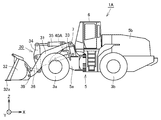
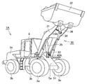
- FIG. 1 is a side view of a wheel loader 1 based on the embodiment.
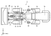
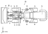
- FIG. 2 is a top view of the wheel loader 1.
- the wheel loader 1 includes a main body 5, a work machine 30, wheels 3 a and 3 b, and a cab 6.
- the wheel loader 1 can be self-propelled when the wheels 3 a and 3 b are rotationally driven, and can perform a desired work using the work machine 30.
- the main body 5 has a front frame 5a and a rear frame 5b.
- the front frame 5a and the rear frame 5b are connected to each other by a center pin 81 so as to be swingable in the left-right direction.
- a pair of steering cylinders 82 are provided across the front frame 5a and the rear frame 5b.
- the steering cylinder 82 is a hydraulic cylinder driven by hydraulic oil from a steering pump (not shown). As the steering cylinder 82 expands and contracts, the front frame 5a swings with respect to the rear frame 5b. Thereby, the advancing direction of the wheel loader 1 is changed.
- the work machine 30 and a pair of front wheels 3a are attached to the front frame 5a.
- the work machine 30 is disposed in front of the main body 5.
- the work machine 30 is driven by hydraulic oil from a hydraulic pump 119 (see FIG. 3).
- the work machine 30 includes a boom 31, a pair of lift cylinders 33, a bucket 32, a bell crank 34, a tilt cylinder 35, and a tilt rod 36 that connects the tip of the bell crank 34 and the bucket 32. ing.
- the boom 31 is rotatably supported by the front frame 5a.
- a base end portion (base end portion) of the boom 31 is swingably attached to the front frame 5 a by a boom pin 7.
- One end of the lift cylinder 33 is attached to the front frame 5a.
- the other end of the lift cylinder 33 is attached to the boom 31.
- the other end of the lift cylinder 33 is preferably attached to the lower end of the boom 31.
- the front frame 5 a and the boom 31 are connected by a lift cylinder 33. As the lift cylinder 33 expands and contracts with the hydraulic oil from the hydraulic pump 119, the boom 31 swings up and down around the boom pin 7.
- FIG. 1 only one of the lift cylinders 33 is shown, and the other is omitted.
- the bucket 32 is rotatably supported at the tip of the boom 31.
- the bucket 32 is instructed by a bucket pin 39 to be swingable at the tip of the boom 31.
- One end of the tilt cylinder 35 is attached to the front frame 5a.
- the other end of the tilt cylinder 35 is attached to the bell crank 34.
- the bell crank 34 and the bucket 32 are connected by a link device (not shown).
- the front frame 5a and the bucket 32 are connected by a tilt cylinder 35, a bell crank 34, and a link device.
- the tilt cylinder 35 expands and contracts with hydraulic oil from the hydraulic pump 119, so that the bucket 32 swings up and down around the bucket pin 39.
- the cab 6 and a pair of rear wheels 3b are attached to the rear frame 5b.
- the cab 6 is mounted on the main body 5.
- the cab 6 is equipped with a seat on which an operator is seated, an operation device to be described later, and the like.
- the wheel loader 1 further includes a sensor 40 for measuring the distance between the dump truck to be loaded and the boom 31.
- the sensor 40 is installed on the boom 31. Therefore, the sensor 40 moves in conjunction with the movement of the boom 31.
- the sensor 40 is installed at a predetermined position of the boom 31 that is closer to the proximal end portion of the boom 31 than the distal end portion of the boom 31.
- the sensor 40 is installed at the lower end of the boom 31.
- the sensor 40 is installed in the vicinity of the boom pin 7.
- the “lower end portion of the boom 31” means the lower half (the half on the ground side) of the boom 31 including the lower surface of the boom 31.
- the sensor 40 measures the distance between the vessel of the dump truck and the boom 31 (hereinafter also referred to as “distance D”).
- the sensor 40 senses the lower end portion of the boom 31.
- the sensor 40 may be any device for measuring a distance, and various devices such as an ultrasonic sensor, a laser sensor, an infrared sensor, and a camera can be used as the sensor 40.
- FIG. 3 is a perspective view of the wheel loader 1.
- the bucket 32 can be raised by raising the boom 31 based on an operator operation. With the excavated material such as earth and sand excavated in the bucket loaded, the operator reduces the tilt angle of the bucket 32 (angle ⁇ in FIG. 14) to load the excavated material on the loading target such as a dump truck. Is possible.
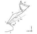
- FIG. 4 is a diagram for explaining the positional relationship between the left boom 31 and the sensor 40.
- the sensor 40 is installed at the lower end 31 a of the boom 31.
- a lens 41 is installed on the tip end side of the boom 31.
- the lens 41 is disposed on the right side of the left boom 31 (closer to the right boom 31), but is not limited thereto.
- the lens 41 may be arranged on the left side of the left boom 31.
- a sensor may be installed on the right boom 31.
- FIG. 5 is a schematic diagram for explaining the sensing range of the sensor 40. As shown in FIG. 5, the sensor 40 is arranged so that the optical axis 48 of the sensor 40 is along the extending direction of the boom 31.
- the sensor 40 senses an area including the lower end 31a of the boom 31. Further, the sensor 40 may sense an area in the lower end portion 31 a of the boom 31 that is closer to the distal end portion than the proximal end portion of the boom 31. In particular, the sensor 40 preferably senses an area from the position where the other end of the lift cylinder 33 is attached to the boom 31 to the tip of the boom 31 at the lower end 31 a of the boom 31. The sensor 40 may sense a part of the area described above.
- the senor 40 can measure the distance between the dump truck as a loading target and the boom 31.
- the information obtained by the sensor 40 is sent to a controller 110 (FIG. 8) described later of the wheel loader 1 for data processing.
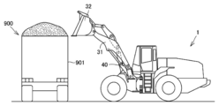
- FIG. 6 is a diagram for explaining a general operator operation during the dump approach.
- the operator performs an accelerator operation in the section Q11. Specifically, the operator steps on an accelerator pedal (not shown). Furthermore, in the section Q11, the operator operates a boom operation lever 122 (FIG. 8) described later in order to raise the boom 31. Thereby, in the section Q11, the wheel loader 1 travels toward the dump truck 900 and the boom raising operation is executed.
- the reason why the operator performs the accelerator operation in the section Q ⁇ b> 11 has a strong meaning for supplying a sufficient amount of oil to the lift cylinder 33 rather than driving the wheel loader 1.
- the engine speed is increased to ensure the output of hydraulic oil from the hydraulic pump. Therefore, even if the operator depresses the brake pedal to decrease the vehicle speed in the section Q11, the operator continues to depress the accelerator pedal.
- the operator stops the accelerator operation and performs the brake operation. Specifically, the operator stops stepping on the accelerator pedal and steps on a brake pedal (not shown). As a result, the operator stops the wheel loader 1 before the dump truck 900. Thereafter, the operator operates a bucket operation lever 123 (FIG. 8) described later to load the earth and sand picked up by the bucket 32 onto the loading platform of the dump truck 900.
- the passing trajectory of the bucket 32 is typically represented as a broken line La.
- FIG. 7 is a diagram illustrating a case where the boom 31 is not raised to a position where the operator can load the excavated material on the vessel 901 of the dump truck 900 during the dump approach.
- FIG. 7A is a diagram showing a dump approach when it is assumed that the output of the sensor 40 is not used.
- FIG. 7B is a diagram showing a dump approach when the output of the sensor 40 is used. As described above, FIG. 7A shows a comparative example for clarifying the feature of FIG.
- the wheel loader 1 (specifically, the controller 110) performs the following control.
- the wheel loader 1 determines whether or not the distance D (the distance between the dump truck 900 and the boom 31) measured by the sensor 40 is equal to or less than a threshold value. When the wheel loader 1 determines that the measured distance D is equal to or less than the threshold value, the wheel loader 1 starts control to raise the boom 31. For example, in the section Q21 in which the measured distance D is not less than or equal to the threshold value, the boom 31 is not raised, but when the wheel loader 1 moves forward to the section Q22 in which the measured distance D is less than or equal to the threshold value, the wheel loader 1 moves the boom 31. Start raising control.
- the wheel loader 1 uses the sensor 40 to measure the distance D between the dump truck 900 and the boom 31.
- the controller 110 of the wheel loader 1 causes the wheel loader to perform a boom raising operation when the distance D measured by the sensor 40 is equal to or less than a threshold value as the wheel loader 1 travels.
- the wheel loader 1 performs the process of moving the boom 31 away from the vessel 901 before the boom 31 collides with the vessel 901 during the dump approach. Therefore, even when the operator has not paid much attention to the position of the front wheel 3a and the confirmation of the position of the boom 31 has been neglected, the boom 31 can be prevented from colliding with the dump truck 900. . Therefore, according to the wheel loader 1, an operator operation at the time of the dump approach can be assisted.
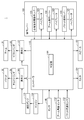
- FIG. 8 is a block diagram showing the system configuration of the wheel loader 1.
- the wheel loader 1 includes a boom 31, a bucket 32, a lift cylinder 33, a tilt cylinder 35, a sensor 40, a controller 110, a boom angle sensor 112, a bucket angle sensor 113, An engine 118, a hydraulic pump 119, an operation lever 120, operation valves 131 and 141, a monitor 151, and a speaker 152 are provided.
- the operation lever 120 includes a forward / reverse switching operation lever 121, a boom operation lever 122, a bucket operation lever 123, and vibrators 124, 125, and 126.
- the controller 110 includes a determination unit 1101.
- the controller 110 controls the overall operation of the wheel loader 1.
- the controller 110 controls the number of revolutions of the engine 118 based on the operation of the accelerator pedal. Further, the controller receives a signal based on an operator operation by the operation lever 120 and causes the wheel loader 1 to execute an operation corresponding to the operation.
- the hydraulic pump 119 is driven by the output of the engine 118.
- the hydraulic pump 119 supplies hydraulic oil to the lift cylinder 33 that drives the boom 31 via the operation valve 131.
- the vertical movement of the boom 31 can be controlled by operating a boom operation lever 122 provided in the cab 6.
- the hydraulic pump 119 supplies hydraulic oil to the tilt cylinder 35 that drives the bucket 32 via the operation valve 141.
- the operation of the bucket 32 can be controlled by operating a bucket operation lever 123 provided in the cab 6.
- the controller 110 sequentially receives sensing results from the sensor 40.
- the determination unit 1101 of the controller 110 determines whether or not the distance D measured by the sensor 40 is equal to or less than the threshold Th during the dump approach. When the determination unit 1101 determines that the distance D is equal to or less than the threshold value Th, the controller 110 starts a process of raising the boom 31.
- the controller 110 receives a signal corresponding to the boom angle from the boom angle sensor 112.
- the controller 110 receives a signal corresponding to the tilt angle from the bucket angle sensor 113.
- a method of using signals (sensing results) output from the boom angle sensor 112 and the bucket angle sensor 113 will be described later.
- the controller 110 displays various images on the monitor 151.
- the controller 110 causes the speaker 152 to output a predetermined sound. A method for using the monitor 151 and the speaker 152 will be described later.
- the vibrator 124 is a device for vibrating the forward / reverse switching operation lever 121.
- Vibrator 125 is a device for vibrating boom operation lever 122.
- Vibrator 126 is a device for vibrating bucket operating lever 123. A method of using the vibrators 124 to 126 will be described later.
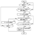
- FIG. 9 is a flowchart for explaining the processing flow of the wheel loader 1.
- the controller 110 determines whether or not the vehicle is moving forward.
- controller 110 determines whether distance D measured by sensor 40 is equal to or smaller than threshold value Th.
- controller 110 determines that the vehicle is not moving forward (NO in step S2), the process returns to step S2.
- step S4 When the controller 110 determines that the distance D is equal to or less than the threshold Th (YES in step S4), the controller 110 starts a process of raising the boom 31 in step S6. When controller 110 determines that distance D is longer than threshold value Th (NO in step S4), the process returns to step S2. In step S8, the controller 110 determines whether or not the distance D measured by the sensor 40 is equal to or less than the threshold value Th.
- controller 110 determines that distance D is longer than threshold value Th (YES in step S8), controller 110 stops the rise of boom 31 in step S14. After step S14, in step S16, the controller 110 determines whether or not the wheel loader 1 is moving forward. If controller 110 determines that the vehicle is moving forward (YES in step S16), the process returns to step S4. When controller 110 determines that the vehicle is not moving forward (NO in step S16), the series of processing ends.
- step S10 the controller 110 determines whether the angle of the boom 31 (boom angle) is the maximum angle. Specifically, the controller 110 determines whether or not the lift cylinder 33 is extended to the stroke end.
- step S10 determines that the angle is the maximum angle (YES in step S10), the controller 110 stops the traveling of the wheel loader 1 in step S12. Typically, the controller 110 applies the brake even when the operator does not perform the brake operation. If controller 110 determines that the angle is not the maximum angle (NO in step S10), the process proceeds to step S8.
- the controller 110 performs control to raise the boom 31 when the distance D is equal to or less than the threshold Th.
- Such control may be forcibly stopped by an operator operation.
- Examples of such an operator operation include an operation of pressing a predetermined button (not shown), an operation of lowering the boom 31 using the boom operation lever 122, and an operation of switching the forward / reverse switching operation lever 121 from the forward movement position to the reverse movement position.
- the operation of switching the forward / reverse switching operation lever 121 from the forward movement position to the reverse movement position is performed even when the wheel loader 1 moves forward (when not stopped).
- the senor 40 is installed at a predetermined position of the boom 31 that is closer to the proximal end portion of the boom 31 than the distal end portion of the boom 31.
- the controller 110 causes the wheel loader 1 to perform an operation of raising the boom 31 as a predetermined operation for avoiding a collision.
- the wheel loader 1 performs a process of moving the boom 31 away from the vessel 901 before the boom 31 collides with the vessel 901 as shown in the section Q22 of FIG. . Therefore, even when the operator fails to confirm the position of the boom 31, it is possible to avoid the boom 31 from colliding with the dump truck 900. Therefore, according to the wheel loader 1, it is possible to assist the operator operation during the dump approach.
- the predetermined position is the lower end 31 a of the boom 31. According to this, it is possible to sense the lower end 31a of the boom 31.
- the sensor 40 senses the lower end 31a of the boom 31. Accordingly, the distance D between the boom 31 and the vessel 901 of the dump truck 900 can be measured.
- the controller 110 stops the traveling of the wheel loader 1 when the angle of the boom 31 reaches the maximum angle. According to this, in a situation where the boom 31 collides with the vessel 901 even if the boom 31 is released as much as possible, it is possible to prevent the boom 31 from colliding with the vessel 901.
- FIG. 10 is a side view of the wheel loader 1A based on the embodiment.
- FIG. 11 is a top view of the wheel loader 1A.
- FIG. 12 is a perspective view of the wheel loader 1A.
- the wheel loader 1 ⁇ / b> A has the same hardware configuration as the wheel loader 1 ⁇ / b> A except that the sensor 40 ⁇ / b> A is provided instead of the sensor 40.
- Sensor 40A is installed on the upper surface of front frame 5a.
- the sensor 40A is installed at a predetermined position closer to the support position of the boom 31 than the front end portion 51 (see FIG. 13) of the front frame 5a. Specifically, it is installed at a position closer to the position of the boom pin 7 than the front end portion of the front frame 5a.
- the sensor 40A is installed between the support position of the left boom 31 and the support position of the tilt cylinder 35 as viewed from above in the Y direction of FIG.
- the sensor 40A may be installed between the support position of the right boom 31 and the support position of the tilt cylinder 35 in the top view.
- the sensor 40A measures the distance D between the dump truck 900 and the boom 31 during the dump approach, similarly to the sensor 40. Specifically, the sensor 40 ⁇ / b> A measures the distance D between the vessel 901 of the dump truck 900 and the boom 31 in the same manner as the sensor 40. Similarly to the sensor 40, the sensor 40A senses the lower end portion of the boom 31 when the boom 31 is raised.
- the sensor 40A may be an apparatus for measuring the distance D, and various devices such as an ultrasonic sensor, a laser sensor, an infrared sensor, and a camera can be used as the sensor 40A.
- FIG. 13 is a schematic diagram for explaining the sensing range of the sensor 40A.
- the sensor 40 ⁇ / b> A is arranged so that the optical axis 49 of the sensor 40 ⁇ / b> A is substantially along the extending direction of the boom 31 when the boom 31 is raised above a predetermined angle.
- the sensing range of the sensor 40A is set in advance assuming a boom angle during the dump approach.
- the sensor 40A senses an area including the lower end 31a of the boom 31. Furthermore, the sensor 40 ⁇ / b> A may sense an area in the lower end portion 31 a of the boom 31 that is closer to the distal end portion than the proximal end portion of the boom 31. In particular, the sensor 40 ⁇ / b> A preferably senses an area from the position where the other end of the lift cylinder 33 is attached to the boom 31 to the tip of the boom 31 at the lower end 31 a of the boom 31. The sensor 40A may sense a part of the area described above.
- the sensor 40A can measure the distance D between the dump truck as the loading target and the boom 31.
- the information obtained by the sensor 40A is sent to the controller 110 of the wheel loader 1A for data processing.
- the same control as the wheel loader 1 is executed. Specifically, when the distance D measured by the sensor 40A is less than or equal to the threshold Th when the wheel loader 1A travels, the controller 110 performs an operation of raising the boom 31 as a predetermined operation for avoiding a collision. To run.
- the wheel loader 1A can move the boom 31 away from the vessel 901 before the boom 31 collides with the vessel 901 during the dump approach. Therefore, even if the operator neglects to confirm the position of the boom 31 by running the wheel loader 1A with the line of sight toward the front wheel 3a, it is possible to avoid the boom 31 from colliding with the dump truck 900. Become.
- Predetermined operation for collision avoidance when the distance D measured by the sensor 40A is less than or equal to the threshold Th when the wheel loader 1A travels, The wheel loader 1 is caused to perform an operation of raising the boom 31 as a predetermined operation.
- the predetermined operation is not limited to the operation of raising the boom 31.
- Controller 110 may output a predetermined notification sound (warning sound) from speaker 152 instead of performing control to raise boom 31.
- the controller 110 may cause the monitor 151 to perform a predetermined warning display. According to these, the operator can notice an abnormality. Specifically, the operator can notice that the wheel loaders 1 and 1A are likely to collide with the dump truck.
- the controller 110 may transmit a command to start vibration to the vibrators 124 to 126.
- the operation levers 121, 122, 123 vibrate due to the vibrations of the vibrators 124-126. This also makes it possible for the operator to notice an abnormality.
- the wheel loader 1, the assembling operation of the boom 31, the output of a predetermined warning sound from the speaker 152, the predetermined warning display on the monitor 151, and the vibrators 124 to 126 are appropriately combined. 1A may be configured.
- FIG. 14 is a diagram for explaining the tilt angle ⁇ of the bucket 32.
- the wheel loader 1 is illustrated.
- the operator makes the tilt angle ⁇ larger than a predetermined angle (hereinafter also referred to as “angle ⁇ 1”).
- angle ⁇ 1 a predetermined angle
- the predetermined operation is not always started, but the predetermined operation is started on the condition that the tilt angle of the bucket 32 is equal to or larger than the predetermined angle ⁇ 1.
- the wheel loaders 1 and 1A may be configured.
- the predetermined operation is executed when the distance D becomes equal to or less than the threshold Th. Is done.
- a predetermined operation is executed even if the distance D is equal to or less than the threshold Th. It will never be done.
- FIG. 15 is a diagram showing the state of unloading.
- the wheel loader 1 is illustrated.
- the operator when the operator loads the excavated material on the vessel 901 of the dump truck 900, the excavated item can be placed in the vessel 901 beyond the height of the vessel 901.
- the operator operates the bucket 32 with the excavated material on the upper side of the vessel 901 by setting the tilt angle of the bucket 32 to a predetermined angle smaller than the angle ⁇ 1 (hereinafter referred to as “angle ⁇ 2”) or less. Drop it on the ground.
- angle ⁇ 2 the angle smaller than the angle ⁇ 1
- the tilt angle ⁇ of the bucket 32 is set to zero degrees (a state where the cutting edge 32a is horizontal to the main body 5), and the earth and sand overflowing from the vessel 901 is transferred to the wheel loader 1, 1A with respect to the dump truck 900. Drop it on the other side of the ground.
- the controller 110 may be configured to stop the execution of the predetermined operation when the wheel loader 1, 1A transitions from the forward state to the reverse state. According to this, it can suppress that unnecessary control is performed.
- a wheel loader for loading excavated material onto a loading object includes a front frame, a bucket, a boom having a tip end connected to the bucket and a base end rotatably supported by the front frame, a loading object, and a boom. And a controller for controlling the operation of the wheel loader. The controller causes the wheel loader to perform a predetermined operation for avoiding a collision when the distance measured by the sensor becomes equal to or less than the threshold value as the wheel loader travels.
- the wheel loader performs a predetermined operation for avoiding the collision before the boom collides with the loading target when moving forward. Therefore, even if the operator fails to confirm the position of the boom, it is possible to avoid colliding with the loading target. Therefore, according to the wheel loader, it is possible to assist the operator's operation when loading the excavated material on the loading object.
- the senor is one of a first position on the boom that is closer to the base end than the front end and a second position on the front frame that is closer to the boom support than the front end of the front frame. Is installed.
- the first position is a lower end portion of the boom.
- the wheel loader can sense the lower end of the boom by the sensor.
- the senor is installed at the first position, and senses an area closer to the tip than the base end at the lower end of the boom.
- the wheel loader can measure the distance between the boom and the loading target.
- the wheel loader further includes a lift cylinder that is attached at one end to the lower end of the boom and drives the boom.
- the sensor is installed at the first position, and senses an area from the position where the lift cylinder is attached to the boom to the tip of the boom at the lower end of the boom.
- the wheel loader can measure the distance between the boom and the loading target.
- the predetermined operation is an operation of raising the boom.
- the wheel loader can move the boom away from the loading target before the boom collides with the loading target during forward movement. Therefore, even when the operator fails to confirm the position of the boom, it is possible to avoid the boom from colliding with the loading target.
- the predetermined operation is an operation for outputting a predetermined notification sound.
- the operator can perform an operation of avoiding the collision with the loading target when the operator hears the notification sound before the boom collides with the loading target.
- an operation lever for operating the wheel loader is further provided.
- the predetermined operation is an operation of vibrating the operation lever.
- the operator can perform an operation of avoiding the collision with the loading target by sensing the vibration of the operation lever before the boom collides with the loading target.
- the controller stops the traveling of the wheel loader when the angle of the boom reaches the maximum angle by a predetermined operation.
- the controller causes the wheel loader to execute a predetermined operation on condition that the bucket tilt angle is equal to or greater than the first value.
- the predetermined operation is an operation of raising the boom.
- the controller stops the operation of raising the boom.
- the wheel loader stops automatic control of raising the boom, so that the operator can unload.
- the controller when the controller receives a predetermined input based on an operator operation, the controller stops execution of the predetermined operation.
- the predetermined operation is an operation of raising the boom.
- the operator operation is an operation for lowering the boom.
- the control for automatically raising the boom can be forcibly stopped by performing the operation of lowering the boom.
- the vehicle further includes a forward / reverse switching lever for switching the wheel loader between forward and reverse.
- the operator operation is an operation in which the forward / reverse switching lever switches from the forward position to the reverse position.
- the controller stops execution of a predetermined operation when the wheel loader transitions from the forward movement state to the reverse movement state.
- the control method is executed in the wheel loader that loads the excavated material on the loading object.
- the control method includes a step of measuring a distance between an object to be loaded and a boom of the wheel loader, a step of determining that the measured distance is equal to or less than a threshold value as the wheel loader travels, And a step of causing the wheel loader to execute a predetermined operation for avoiding a collision when the detected distance is equal to or less than a threshold value.
- the wheel loader performs a predetermined operation for avoiding the collision before the boom collides with the loading target at the time of forward movement. Therefore, even if the operator fails to confirm the position of the boom, it is possible to avoid colliding with the loading target. Therefore, according to the wheel loader, it is possible to assist the operator's operation when loading the excavated material on the loading object.
- 1,1A wheel loader 3a front wheel, 3b rear wheel, 5 main body, 5a front frame, 5b rear frame, 6 cab, 7 boom pin, 30 working machine, 31 boom 31a lower end, 32 bucket, 32a cutting edge, 33 lift cylinder 34 bell crank, 35 tilt cylinder, 36 tilt rod, 39 bucket pin, 40, 40A sensor, 41 lens, 48, 49 optical axis, 900 dump truck, 901 vessel.
Landscapes
- Engineering & Computer Science (AREA)
- Mining & Mineral Resources (AREA)
- Civil Engineering (AREA)
- General Engineering & Computer Science (AREA)
- Structural Engineering (AREA)
- Mechanical Engineering (AREA)
- Physics & Mathematics (AREA)
- Acoustics & Sound (AREA)
- Human Computer Interaction (AREA)
- Operation Control Of Excavators (AREA)
- Component Parts Of Construction Machinery (AREA)
Abstract
Description
<全体構成>
図1は、実施形態に基づくホイールローダ1の側面図である。図2は、ホイールローダ1の上面図である。
図6は、ダンプアプローチ時における一般的なオペレータ操作を説明するための図である。図6に示すように、オペレータは、区間Q11では、アクセル操作を行う。具体的には、オペレータは、図示しないアクセルペダルを踏む。さらに、オペレータは、区間Q11では、ブーム31を上げるために、後述するブーム操作レバー122(図8)を操作する。これにより、区間Q11では、ホイールローダ1がダンプトラック900に向かって走行するとともに、ブーム上げ操作が実行される。
図8は、ホイールローダ1のシステム構成を表したブロック図である。図8に示すように、ホイールローダ1は、ブーム31と、バケット32と、リフトシリンダ33と、チルトシリンダ35と、センサ40と、コントローラ110と、ブーム角度センサ112と、バケット角度センサ113と、エンジン118と、油圧ポンプ119と、操作レバー120と、操作弁131,141と、モニタ151、スピーカ152とを備える。
図9は、ホイールローダ1の処理の流れを説明するためのフローチャートである。図9に示すように、ステップS2において、コントローラ110は、前進中か否かを判断する。コントローラ110は、前進中であると判断した場合(ステップS2においてYES)、ステップS4において、センサ40によって測定された距離Dが閾値Th以下であるか否かを判断する。コントローラ110は、前進中でないと判断した場合(ステップS2においてNO)、処理をステップS2に戻す。
(1)以上のように、センサ40は、ブーム31の先端部よりもブーム31の基端部に近い、ブーム31の所定位置に設置されている。コントローラ110は、ホイールローダ1が走行することによってセンサ40によって測定された距離Dが閾値Th以下になると、衝突回避のための所定の動作としてブーム31を上げる動作をホイールローダ1に実行させる。
本実施の形態に係るホイールローダについて、図面を参照して説明する。なお、実施の形態1のホイールローダ1と異なる構成について説明し、ホイールローダ1と同様な構成については、その説明を繰り返さない。
実施の形態1に係るホイールローダ1および実施の形態2に係るホイールローダ1Aとの変形例については、図面を参照して説明する。
上記の実施の形態1,2においては、コントローラ110は、ホイールローダ1Aが走行することによってセンサ40Aによって測定された距離Dが閾値Th以下になると、所定の動作としてブーム31を上げる動作をホイールローダ1に実行させる。しかしながら、所定の動作は、ブーム31を上昇させる動作に限定されるものではない。
図14は、バケット32のチルト角度θを説明するための図である。なお、図14では、ホイールローダ1を例示している。図14に示すように、ダンプアプローチ時には、土砂等の掘削物がバケット32に積載されているため、オペレータは、チルト角度θを所定の角度(以下、「角度θ1」とも称する)よりも大きくする必要がある。
ホイールローダ1、1Aの後進時には、距離Dが閾値Th以下であっても、ブーム31がベッセル901に衝突することはないため、ブーム31の上昇等の所定の動作を実行させる必要はない。そこで、ホイールローダ1,1Aが前進状態から後進状態に遷移すると、上記所定の動作の実行を停止させるように、コントローラ110を構成してもよい。これによれば、不要な制御が実行されることを抑制できる。
掘削物を積込対象に積み込むホイールローダは、フロントフレームと、バケットと、先端部がバケットに接続され、かつ基端部がフロントフレームに回転可能に支持されたブームと、積込対象とブームとの間の距離を測定するためのセンサと、ホイールローダの動作を制御するコントローラとを備える。コントローラは、ホイールローダが走行することによってセンサによって測定された距離が閾値以下になると、衝突回避のための所定の動作をホイールローダに実行させる。
上記の構成によれば、ホイールローダは、前進時において、ブームが積込対象に衝突する前に、ブームを積込対象から遠ざけることができる。それゆえ、オペレータがブームの位置の確認を怠った場合であっても、ブームが積込対象に衝突してしまうことを回避可能となる。
上記の構成によれば、ブームが積込対象に衝突する前にオペレータが報知音を聞くことにより、オペレータは、積込対象との衝突を回避する操作を行うことが可能となる。
Claims (16)
- 掘削物を積込対象に積み込むホイールローダであって、
フロントフレームと、
バケットと、
先端部が前記バケットに接続され、かつ基端部が前記フロントフレームに回転可能に支持されたブームと、
前記積込対象と前記ブームとの間の距離を測定するためのセンサと、
前記ホイールローダの動作を制御するコントローラとを備え、
前記コントローラは、前記ホイールローダが走行することによって前記センサによって測定された距離が閾値以下になると、衝突回避のための所定の動作を前記ホイールローダに実行させる、ホイールローダ。 - 前記センサは、前記先端部よりも前記基端部に近い、前記ブームにおける第1の位置、および前記フロントフレームの前端部よりも前記ブームの支持位置に近い、前記フロントフレームにおける第2の位置のうちのいずれかに設置されている、請求項1に記載のホイールローダ。
- 前記第1の位置は、前記ブームの下端部である、請求項2に記載のホイールローダ。
- 前記センサは、前記第1の位置に設置されており、かつ前記ブームの下端部における、前記基端部よりも前記先端部に近いエリアをセンシングする、請求項2または3に記載のホイールローダ。
- 一端が前記ブームの下端部に取り付けられ、かつ前記ブームを駆動するリフトシリンダをさらに備え、
前記センサは、前記第1の位置に設置されており、かつ前記ブームの下端部における、前記リフトシリンダが前記ブームに取り付けられる箇所から前記ブームの先端部までのエリアをセンシングする、請求項2または3に記載のホイールローダ。 - 前記所定の動作は、前記ブームを上げる動作である、請求項1から5のいずれか1項に記載のホイールローダ。
- 前記所定の動作は、所定の報知音を出力する動作である、請求項1から5のいずれか1項に記載のホイールローダ。
- 前記ホイールローダを操作するための操作レバーをさらに備え、
前記所定の動作は、前記操作レバーを振動させる動作である、請求項1から5のいずれか1項に記載のホイールローダ。 - 前記コントローラは、前記所定の動作によって前記ブームの角度が最大角となると、前記ホイールローダの走行を停止させる、請求項6に記載のホイールローダ。
- 前記コントローラは、前記バケットのチルト角度が第1の値以上であることを条件に、前記所定の動作を前記ホイールローダに実行させる、請求項1から9のいずれか1項に記載のホイールローダ。
- 前記所定の動作は、前記ブームを上げる動作であって、
前記コントローラは、前記チルト角度が前記第1の値よりも小さい第2の値以下である場合、前記ブームを上げる動作を停止させる、請求項10に記載のホイールローダ。 - 前記コントローラは、オペレータ操作に基づく所定の入力を受け付けた場合には、前記所定の動作の実行を停止させる、請求項1から11のいずれか1項に記載のホイールローダ。
- 前記所定の動作は、前記ブームを上げる動作であって、
前記オペレータ操作は、前記ブームを下げる操作である、請求項12に記載のホイールローダ。 - 前記ホイールローダの前進と後進とを切り替える前後進切替レバーをさらに備え、
前記オペレータ操作は、前記前後進切替レバーが前進位置から後進位置に切り替える操作である、請求項12に記載のホイールローダ。 - 前記コントローラは、前記ホイールローダが前進状態から後進状態に遷移すると、前記所定の動作の実行を停止させる、請求項1から13のいずれか1項に記載のホイールローダ。
- 掘削物を積込対象に積み込むホイールローダの制御方法であって、
前記積込対象と前記ホイールローダのブームとの間の距離を測定するステップと、
前記ホイールローダが走行することによって、測定された前記距離が閾値以下になることを判断するステップと、
測定された前記距離が前記閾値以下になると、衝突回避のための所定の動作を前記ホイールローダに実行させるステップとを備える、ホイールローダの制御方法。
Priority Applications (6)
| Application Number | Priority Date | Filing Date | Title |
|---|---|---|---|
| CN201780016921.9A CN108779628B (zh) | 2016-08-31 | 2017-08-14 | 轮式装载机以及轮式装载机的控制方法 |
| EP17846112.5A EP3412838B1 (en) | 2016-08-31 | 2017-08-14 | Wheel loader and wheel loader control method |
| US16/082,284 US10815640B2 (en) | 2016-08-31 | 2017-08-14 | Wheel loader and method for controlling wheel loader |
| JP2018537098A JP6914943B2 (ja) | 2016-08-31 | 2017-08-14 | ホイールローダおよびホイールローダの制御方法 |
| US17/023,673 US11674285B2 (en) | 2016-08-31 | 2020-09-17 | Wheel loader and method for controlling wheel loader |
| US18/141,646 US20230257960A1 (en) | 2016-08-31 | 2023-05-01 | Wheel loader and method for controlling wheel loader |
Applications Claiming Priority (2)
| Application Number | Priority Date | Filing Date | Title |
|---|---|---|---|
| JP2016169498 | 2016-08-31 | ||
| JP2016-169498 | 2016-08-31 |
Related Child Applications (2)
| Application Number | Title | Priority Date | Filing Date |
|---|---|---|---|
| US16/082,284 A-371-Of-International US10815640B2 (en) | 2016-08-31 | 2017-08-14 | Wheel loader and method for controlling wheel loader |
| US17/023,673 Continuation US11674285B2 (en) | 2016-08-31 | 2020-09-17 | Wheel loader and method for controlling wheel loader |
Publications (1)
| Publication Number | Publication Date |
|---|---|
| WO2018043104A1 true WO2018043104A1 (ja) | 2018-03-08 |
Family
ID=61300572
Family Applications (1)
| Application Number | Title | Priority Date | Filing Date |
|---|---|---|---|
| PCT/JP2017/029271 WO2018043104A1 (ja) | 2016-08-31 | 2017-08-14 | ホイールローダおよびホイールローダの制御方法 |
Country Status (5)
| Country | Link |
|---|---|
| US (3) | US10815640B2 (ja) |
| EP (1) | EP3412838B1 (ja) |
| JP (1) | JP6914943B2 (ja) |
| CN (1) | CN108779628B (ja) |
| WO (1) | WO2018043104A1 (ja) |
Cited By (6)
| Publication number | Priority date | Publication date | Assignee | Title |
|---|---|---|---|---|
| JP2019190238A (ja) * | 2018-04-27 | 2019-10-31 | 株式会社小松製作所 | 積込機械の制御装置及び積込機械の制御方法 |
| WO2019207981A1 (ja) * | 2018-04-27 | 2019-10-31 | 株式会社小松製作所 | 積込機械の制御装置及び積込機械の制御方法 |
| JP2020165108A (ja) * | 2019-03-28 | 2020-10-08 | 日立建機株式会社 | 作業車両 |
| JP2020193503A (ja) * | 2019-05-29 | 2020-12-03 | ナブテスコ株式会社 | 作業機械の操縦支援システム、作業機械の操縦支援方法、操縦支援システムの保守支援方法、建設機械 |
| WO2021059655A1 (ja) * | 2019-09-26 | 2021-04-01 | 日立建機株式会社 | 制御システム |
| WO2022070562A1 (ja) * | 2020-09-30 | 2022-04-07 | 株式会社小松製作所 | 作業機械 |
Families Citing this family (17)
| Publication number | Priority date | Publication date | Assignee | Title |
|---|---|---|---|---|
| US10570582B2 (en) * | 2016-11-23 | 2020-02-25 | Caterpillar Inc. | System and method for operating a material-handling machine |
| DE102017215379A1 (de) * | 2017-09-01 | 2019-03-07 | Robert Bosch Gmbh | Verfahren zur Ermittlung einer Kollisionsgefahr |
| EP3724862B1 (en) * | 2017-12-14 | 2022-10-19 | Volvo Construction Equipment AB | Method for alerting a person near a vehicle when said vehicle performs a movement and vehicle |
| JP7127313B2 (ja) * | 2018-03-19 | 2022-08-30 | コベルコ建機株式会社 | 建設機械 |
| US10883256B2 (en) * | 2018-05-25 | 2021-01-05 | Deere & Company | Object responsive control system for a work machine |
| WO2018199342A1 (ja) * | 2018-06-19 | 2018-11-01 | 株式会社小松製作所 | 作業車両の制御システム及び作業車両の制御方法 |
| CN114174596B (zh) * | 2019-09-18 | 2024-03-08 | 住友重机械工业株式会社 | 挖土机 |
| JP7283332B2 (ja) * | 2019-09-26 | 2023-05-30 | コベルコ建機株式会社 | 容器計測システム |
| JP7306191B2 (ja) * | 2019-09-26 | 2023-07-11 | コベルコ建機株式会社 | 輸送車位置判定装置 |
| US11401684B2 (en) | 2020-03-31 | 2022-08-02 | Caterpillar Inc. | Perception-based alignment system and method for a loading machine |
| AU2020468174A1 (en) * | 2020-09-15 | 2023-03-02 | Sandvik Mining And Construction Oy | Mining machine with a support structure for measurement sensors |
| US11946230B2 (en) | 2020-10-28 | 2024-04-02 | Deere & Company | Container load assist system and method for a work vehicle |
| EP4269704A1 (en) * | 2020-12-23 | 2023-11-01 | Volvo Construction Equipment AB | Excavator and method and device for controlling excavator |
| US11939748B2 (en) | 2021-03-29 | 2024-03-26 | Joy Global Surface Mining Inc | Virtual track model for a mining machine |
| US11987961B2 (en) | 2021-03-29 | 2024-05-21 | Joy Global Surface Mining Inc | Virtual field-based track protection for a mining machine |
| US11879231B2 (en) | 2021-04-19 | 2024-01-23 | Deere & Company | System and method of selective automation of loading operation stages for self-propelled work vehicles |
| US20230064337A1 (en) | 2021-08-26 | 2023-03-02 | Caterpillar Inc. | Methods and systems for implementing a lock-out command on lever machines |
Citations (7)
| Publication number | Priority date | Publication date | Assignee | Title |
|---|---|---|---|---|
| JPH06193098A (ja) * | 1992-12-24 | 1994-07-12 | Komatsu Ltd | 自走式作業車両の制御装置 |
| JPH101968A (ja) * | 1996-06-18 | 1998-01-06 | Hitachi Constr Mach Co Ltd | 油圧建設機械の自動軌跡制御装置 |
| JPH1088625A (ja) * | 1996-09-13 | 1998-04-07 | Komatsu Ltd | 自動掘削機、自動掘削方法および自動積み込み方法 |
| JP2003184131A (ja) * | 2001-12-19 | 2003-07-03 | Hitachi Constr Mach Co Ltd | 建設機械の操作装置 |
| JP2006195877A (ja) * | 2005-01-17 | 2006-07-27 | Hitachi Constr Mach Co Ltd | 作業機械 |
| JP2007023486A (ja) * | 2005-07-12 | 2007-02-01 | Shin Caterpillar Mitsubishi Ltd | 作業機械における接触回避制御装置 |
| JP2008144378A (ja) * | 2006-12-06 | 2008-06-26 | Shin Caterpillar Mitsubishi Ltd | 遠隔操縦作業機の制御装置 |
Family Cites Families (18)
| Publication number | Priority date | Publication date | Assignee | Title |
|---|---|---|---|---|
| JP3537099B2 (ja) * | 1993-07-16 | 2004-06-14 | 株式会社小松製作所 | 産業車両のバケット角制御装置 |
| US5528498A (en) * | 1994-06-20 | 1996-06-18 | Caterpillar Inc. | Laser referenced swing sensor |
| JP2867332B2 (ja) * | 1996-09-03 | 1999-03-08 | 株式会社レンタルのニッケン | 深掘り掘削機の運動規制機構 |
| US6108949A (en) * | 1997-12-19 | 2000-08-29 | Carnegie Mellon University | Method and apparatus for determining an excavation strategy |
| JP4082646B2 (ja) * | 1999-11-19 | 2008-04-30 | 株式会社小松製作所 | 排土板の前方監視装置付き車両 |
| FI115678B (fi) * | 2003-03-25 | 2005-06-15 | Sandvik Tamrock Oy | Järjestely kaivosajoneuvon törmäyksenestoon |
| JP2008303574A (ja) | 2007-06-06 | 2008-12-18 | Hitachi Constr Mach Co Ltd | 作業機械 |
| JP4948493B2 (ja) * | 2008-08-28 | 2012-06-06 | 日立建機株式会社 | 建設機械 |
| JP5920953B2 (ja) * | 2011-09-23 | 2016-05-24 | ボルボ コンストラクション イクイップメント アーベー | バケットを備えた作業機械のアタック姿勢を選択する方法 |
| US9206587B2 (en) * | 2012-03-16 | 2015-12-08 | Harnischfeger Technologies, Inc. | Automated control of dipper swing for a shovel |
| US8768583B2 (en) * | 2012-03-29 | 2014-07-01 | Harnischfeger Technologies, Inc. | Collision detection and mitigation systems and methods for a shovel |
| CN105934686B (zh) * | 2014-01-30 | 2019-07-16 | 西门子工业公司 | 用于确定n+1维环境模型的方法和设备及采矿装置 |
| JP6342705B2 (ja) * | 2014-05-12 | 2018-06-13 | 古河ユニック株式会社 | 作業機用ブーム衝突回避装置 |
| JP2016065422A (ja) * | 2014-09-26 | 2016-04-28 | 株式会社日立製作所 | 外界認識装置および外界認識装置を用いた掘削機械 |
| CN204475392U (zh) * | 2014-12-30 | 2015-07-15 | 阿特拉斯工程机械有限公司 | 挖掘机驾驶室防碰装置 |
| JP6419585B2 (ja) * | 2015-01-13 | 2018-11-07 | 株式会社小松製作所 | 掘削機械、掘削機械の制御方法及び掘削システム |
| US10094093B2 (en) * | 2015-11-16 | 2018-10-09 | Caterpillar Inc. | Machine onboard activity and behavior classification |
| WO2018051511A1 (ja) * | 2016-09-16 | 2018-03-22 | 日立建機株式会社 | 作業機械 |
-
2017
- 2017-08-14 EP EP17846112.5A patent/EP3412838B1/en active Active
- 2017-08-14 US US16/082,284 patent/US10815640B2/en active Active
- 2017-08-14 CN CN201780016921.9A patent/CN108779628B/zh active Active
- 2017-08-14 WO PCT/JP2017/029271 patent/WO2018043104A1/ja active Application Filing
- 2017-08-14 JP JP2018537098A patent/JP6914943B2/ja active Active
-
2020
- 2020-09-17 US US17/023,673 patent/US11674285B2/en active Active
-
2023
- 2023-05-01 US US18/141,646 patent/US20230257960A1/en active Pending
Patent Citations (7)
| Publication number | Priority date | Publication date | Assignee | Title |
|---|---|---|---|---|
| JPH06193098A (ja) * | 1992-12-24 | 1994-07-12 | Komatsu Ltd | 自走式作業車両の制御装置 |
| JPH101968A (ja) * | 1996-06-18 | 1998-01-06 | Hitachi Constr Mach Co Ltd | 油圧建設機械の自動軌跡制御装置 |
| JPH1088625A (ja) * | 1996-09-13 | 1998-04-07 | Komatsu Ltd | 自動掘削機、自動掘削方法および自動積み込み方法 |
| JP2003184131A (ja) * | 2001-12-19 | 2003-07-03 | Hitachi Constr Mach Co Ltd | 建設機械の操作装置 |
| JP2006195877A (ja) * | 2005-01-17 | 2006-07-27 | Hitachi Constr Mach Co Ltd | 作業機械 |
| JP2007023486A (ja) * | 2005-07-12 | 2007-02-01 | Shin Caterpillar Mitsubishi Ltd | 作業機械における接触回避制御装置 |
| JP2008144378A (ja) * | 2006-12-06 | 2008-06-26 | Shin Caterpillar Mitsubishi Ltd | 遠隔操縦作業機の制御装置 |
Cited By (14)
| Publication number | Priority date | Publication date | Assignee | Title |
|---|---|---|---|---|
| JP7121532B2 (ja) | 2018-04-27 | 2022-08-18 | 株式会社小松製作所 | 積込機械の制御装置及び積込機械の制御方法 |
| WO2019207981A1 (ja) * | 2018-04-27 | 2019-10-31 | 株式会社小松製作所 | 積込機械の制御装置及び積込機械の制御方法 |
| JP2019190237A (ja) * | 2018-04-27 | 2019-10-31 | 株式会社小松製作所 | 積込機械の制御装置及び積込機械の制御方法 |
| WO2019207982A1 (ja) * | 2018-04-27 | 2019-10-31 | 株式会社小松製作所 | 積込機械の制御装置及び積込機械の制御方法 |
| JP2019190238A (ja) * | 2018-04-27 | 2019-10-31 | 株式会社小松製作所 | 積込機械の制御装置及び積込機械の制御方法 |
| US11885096B2 (en) | 2018-04-27 | 2024-01-30 | Komatsu Ltd. | Loading machine control device and loading machine control method |
| JP6995687B2 (ja) | 2018-04-27 | 2022-01-17 | 株式会社小松製作所 | 積込機械の制御装置及び積込機械の制御方法 |
| US11821168B2 (en) | 2018-04-27 | 2023-11-21 | Komatsu Ltd. | Control device for loading machine and control method for loading machine |
| JP2020165108A (ja) * | 2019-03-28 | 2020-10-08 | 日立建機株式会社 | 作業車両 |
| JP2020193503A (ja) * | 2019-05-29 | 2020-12-03 | ナブテスコ株式会社 | 作業機械の操縦支援システム、作業機械の操縦支援方法、操縦支援システムの保守支援方法、建設機械 |
| WO2021059655A1 (ja) * | 2019-09-26 | 2021-04-01 | 日立建機株式会社 | 制御システム |
| JP7282644B2 (ja) | 2019-09-26 | 2023-05-29 | 日立建機株式会社 | 制御システム |
| JP2021050575A (ja) * | 2019-09-26 | 2021-04-01 | 日立建機株式会社 | 制御システム |
| WO2022070562A1 (ja) * | 2020-09-30 | 2022-04-07 | 株式会社小松製作所 | 作業機械 |
Also Published As
| Publication number | Publication date |
|---|---|
| EP3412838A4 (en) | 2019-08-28 |
| JPWO2018043104A1 (ja) | 2019-06-24 |
| CN108779628A (zh) | 2018-11-09 |
| US20190093311A1 (en) | 2019-03-28 |
| EP3412838A1 (en) | 2018-12-12 |
| US11674285B2 (en) | 2023-06-13 |
| JP6914943B2 (ja) | 2021-08-04 |
| US10815640B2 (en) | 2020-10-27 |
| CN108779628B (zh) | 2021-06-08 |
| EP3412838B1 (en) | 2020-11-04 |
| US20230257960A1 (en) | 2023-08-17 |
| US20210032837A1 (en) | 2021-02-04 |
Similar Documents
| Publication | Publication Date | Title |
|---|---|---|
| WO2018043104A1 (ja) | ホイールローダおよびホイールローダの制御方法 | |
| WO2018043091A1 (ja) | ホイールローダおよびホイールローダの制御方法 | |
| CN110088035B (zh) | 起重机 | |
| JP7450083B2 (ja) | 周辺監視システム及び周辺監視方法 | |
| EP2924176B1 (en) | Front loader | |
| US8267480B2 (en) | Method and a device for controlling a vehicle comprising a dump body | |
| EP3848516B1 (en) | System and method for controlling construction machinery | |
| JP2012112108A (ja) | 作業機械の周囲監視装置 | |
| WO2018151310A1 (ja) | 作業車両および作業車両の制御方法 | |
| JP7000957B2 (ja) | 作業機械操縦装置 | |
| JP5261832B2 (ja) | 運搬車両の後方視界表示システム | |
| US20220145588A1 (en) | Work machine | |
| WO2022209176A1 (ja) | 作業機械の走行システムおよび作業機械の制御方法 | |
| US11821171B2 (en) | Work machine | |
| JP5778796B2 (ja) | 運搬車両の後方視界表示システム | |
| WO2024043075A1 (ja) | 作業機械、作業機械を含むシステム、および作業機械の制御方法 | |
| JP5462352B2 (ja) | 運搬車両の後方視界表示システム | |
| US20240117604A1 (en) | Automatic mode for object detection range setting | |
| WO2024057961A1 (ja) | 作業機械を含むシステム、作業機械のコントローラ、および作業機械の制御方法 | |
| WO2024057959A1 (ja) | 作業機械を含むシステム、作業機械のコントローラ、および作業機械の制御方法 | |
| WO2024062899A1 (ja) | 作業機械を含むシステム、および作業機械の制御方法 | |
| WO2024043074A1 (ja) | 作業機械、作業機械を含むシステム、および作業機械の制御方法 | |
| JP2019014584A (ja) | クレーン車 |
Legal Events
| Date | Code | Title | Description |
|---|---|---|---|
| WWE | Wipo information: entry into national phase |
Ref document number: 2018537098 Country of ref document: JP |
|
| WWE | Wipo information: entry into national phase |
Ref document number: 2017846112 Country of ref document: EP |
|
| ENP | Entry into the national phase |
Ref document number: 2017846112 Country of ref document: EP Effective date: 20180904 |
|
| 121 | Ep: the epo has been informed by wipo that ep was designated in this application |
Ref document number: 17846112 Country of ref document: EP Kind code of ref document: A1 |
|
| NENP | Non-entry into the national phase |
Ref country code: DE |