EP3412838B1 - Wheel loader and wheel loader control method - Google Patents
Wheel loader and wheel loader control method Download PDFInfo
- Publication number
- EP3412838B1 EP3412838B1 EP17846112.5A EP17846112A EP3412838B1 EP 3412838 B1 EP3412838 B1 EP 3412838B1 EP 17846112 A EP17846112 A EP 17846112A EP 3412838 B1 EP3412838 B1 EP 3412838B1
- Authority
- EP
- European Patent Office
- Prior art keywords
- boom
- wheel loader
- sensor
- controller
- action
- Prior art date
- Legal status (The legal status is an assumption and is not a legal conclusion. Google has not performed a legal analysis and makes no representation as to the accuracy of the status listed.)
- Active
Links
- 238000000034 method Methods 0.000 title claims description 7
- 230000007704 transition Effects 0.000 claims description 3
- 238000013459 approach Methods 0.000 description 20
- 238000012545 processing Methods 0.000 description 9
- 239000010720 hydraulic oil Substances 0.000 description 7
- 239000002689 soil Substances 0.000 description 7
- 230000001133 acceleration Effects 0.000 description 3
- 230000008602 contraction Effects 0.000 description 3
- 238000012986 modification Methods 0.000 description 3
- 230000004048 modification Effects 0.000 description 3
- 230000003287 optical effect Effects 0.000 description 3
- 230000002159 abnormal effect Effects 0.000 description 2
- 238000009412 basement excavation Methods 0.000 description 2
- 230000007423 decrease Effects 0.000 description 2
- 238000010586 diagram Methods 0.000 description 2
- 230000000007 visual effect Effects 0.000 description 2
- 230000000052 comparative effect Effects 0.000 description 1
- 239000000470 constituent Substances 0.000 description 1
- 230000000694 effects Effects 0.000 description 1
- 238000005259 measurement Methods 0.000 description 1
- 239000003921 oil Substances 0.000 description 1
Images


Classifications
-
- E—FIXED CONSTRUCTIONS
- E02—HYDRAULIC ENGINEERING; FOUNDATIONS; SOIL SHIFTING
- E02F—DREDGING; SOIL-SHIFTING
- E02F3/00—Dredgers; Soil-shifting machines
- E02F3/04—Dredgers; Soil-shifting machines mechanically-driven
- E02F3/28—Dredgers; Soil-shifting machines mechanically-driven with digging tools mounted on a dipper- or bucket-arm, i.e. there is either one arm or a pair of arms, e.g. dippers, buckets
- E02F3/36—Component parts
- E02F3/42—Drives for dippers, buckets, dipper-arms or bucket-arms
- E02F3/43—Control of dipper or bucket position; Control of sequence of drive operations
- E02F3/431—Control of dipper or bucket position; Control of sequence of drive operations for bucket-arms, front-end loaders, dumpers or the like
-
- E—FIXED CONSTRUCTIONS
- E02—HYDRAULIC ENGINEERING; FOUNDATIONS; SOIL SHIFTING
- E02F—DREDGING; SOIL-SHIFTING
- E02F3/00—Dredgers; Soil-shifting machines
- E02F3/04—Dredgers; Soil-shifting machines mechanically-driven
- E02F3/28—Dredgers; Soil-shifting machines mechanically-driven with digging tools mounted on a dipper- or bucket-arm, i.e. there is either one arm or a pair of arms, e.g. dippers, buckets
- E02F3/36—Component parts
- E02F3/42—Drives for dippers, buckets, dipper-arms or bucket-arms
- E02F3/422—Drive systems for bucket-arms, front-end loaders, dumpers or the like
-
- B—PERFORMING OPERATIONS; TRANSPORTING
- B60—VEHICLES IN GENERAL
- B60Q—ARRANGEMENT OF SIGNALLING OR LIGHTING DEVICES, THE MOUNTING OR SUPPORTING THEREOF OR CIRCUITS THEREFOR, FOR VEHICLES IN GENERAL
- B60Q5/00—Arrangement or adaptation of acoustic signal devices
- B60Q5/005—Arrangement or adaptation of acoustic signal devices automatically actuated
-
- B—PERFORMING OPERATIONS; TRANSPORTING
- B60—VEHICLES IN GENERAL
- B60Q—ARRANGEMENT OF SIGNALLING OR LIGHTING DEVICES, THE MOUNTING OR SUPPORTING THEREOF OR CIRCUITS THEREFOR, FOR VEHICLES IN GENERAL
- B60Q9/00—Arrangement or adaptation of signal devices not provided for in one of main groups B60Q1/00 - B60Q7/00, e.g. haptic signalling
- B60Q9/008—Arrangement or adaptation of signal devices not provided for in one of main groups B60Q1/00 - B60Q7/00, e.g. haptic signalling for anti-collision purposes
-
- E—FIXED CONSTRUCTIONS
- E02—HYDRAULIC ENGINEERING; FOUNDATIONS; SOIL SHIFTING
- E02F—DREDGING; SOIL-SHIFTING
- E02F3/00—Dredgers; Soil-shifting machines
- E02F3/04—Dredgers; Soil-shifting machines mechanically-driven
- E02F3/28—Dredgers; Soil-shifting machines mechanically-driven with digging tools mounted on a dipper- or bucket-arm, i.e. there is either one arm or a pair of arms, e.g. dippers, buckets
- E02F3/34—Dredgers; Soil-shifting machines mechanically-driven with digging tools mounted on a dipper- or bucket-arm, i.e. there is either one arm or a pair of arms, e.g. dippers, buckets with bucket-arms, i.e. a pair of arms, e.g. manufacturing processes, form, geometry, material of bucket-arms directly pivoted on the frames of tractors or self-propelled machines
-
- E—FIXED CONSTRUCTIONS
- E02—HYDRAULIC ENGINEERING; FOUNDATIONS; SOIL SHIFTING
- E02F—DREDGING; SOIL-SHIFTING
- E02F3/00—Dredgers; Soil-shifting machines
- E02F3/04—Dredgers; Soil-shifting machines mechanically-driven
- E02F3/28—Dredgers; Soil-shifting machines mechanically-driven with digging tools mounted on a dipper- or bucket-arm, i.e. there is either one arm or a pair of arms, e.g. dippers, buckets
- E02F3/36—Component parts
- E02F3/42—Drives for dippers, buckets, dipper-arms or bucket-arms
- E02F3/43—Control of dipper or bucket position; Control of sequence of drive operations
- E02F3/431—Control of dipper or bucket position; Control of sequence of drive operations for bucket-arms, front-end loaders, dumpers or the like
- E02F3/434—Control of dipper or bucket position; Control of sequence of drive operations for bucket-arms, front-end loaders, dumpers or the like providing automatic sequences of movements, e.g. automatic dumping or loading, automatic return-to-dig
-
- E—FIXED CONSTRUCTIONS
- E02—HYDRAULIC ENGINEERING; FOUNDATIONS; SOIL SHIFTING
- E02F—DREDGING; SOIL-SHIFTING
- E02F9/00—Component parts of dredgers or soil-shifting machines, not restricted to one of the kinds covered by groups E02F3/00 - E02F7/00
- E02F9/08—Superstructures; Supports for superstructures
- E02F9/0858—Arrangement of component parts installed on superstructures not otherwise provided for, e.g. electric components, fenders, air-conditioning units
-
- E—FIXED CONSTRUCTIONS
- E02—HYDRAULIC ENGINEERING; FOUNDATIONS; SOIL SHIFTING
- E02F—DREDGING; SOIL-SHIFTING
- E02F9/00—Component parts of dredgers or soil-shifting machines, not restricted to one of the kinds covered by groups E02F3/00 - E02F7/00
- E02F9/20—Drives; Control devices
- E02F9/2004—Control mechanisms, e.g. control levers
-
- E—FIXED CONSTRUCTIONS
- E02—HYDRAULIC ENGINEERING; FOUNDATIONS; SOIL SHIFTING
- E02F—DREDGING; SOIL-SHIFTING
- E02F9/00—Component parts of dredgers or soil-shifting machines, not restricted to one of the kinds covered by groups E02F3/00 - E02F7/00
- E02F9/20—Drives; Control devices
- E02F9/2025—Particular purposes of control systems not otherwise provided for
- E02F9/2033—Limiting the movement of frames or implements, e.g. to avoid collision between implements and the cabin
-
- E—FIXED CONSTRUCTIONS
- E02—HYDRAULIC ENGINEERING; FOUNDATIONS; SOIL SHIFTING
- E02F—DREDGING; SOIL-SHIFTING
- E02F9/00—Component parts of dredgers or soil-shifting machines, not restricted to one of the kinds covered by groups E02F3/00 - E02F7/00
- E02F9/24—Safety devices, e.g. for preventing overload
-
- E—FIXED CONSTRUCTIONS
- E02—HYDRAULIC ENGINEERING; FOUNDATIONS; SOIL SHIFTING
- E02F—DREDGING; SOIL-SHIFTING
- E02F9/00—Component parts of dredgers or soil-shifting machines, not restricted to one of the kinds covered by groups E02F3/00 - E02F7/00
- E02F9/26—Indicating devices
- E02F9/261—Surveying the work-site to be treated
- E02F9/262—Surveying the work-site to be treated with follow-up actions to control the work tool, e.g. controller
-
- E—FIXED CONSTRUCTIONS
- E02—HYDRAULIC ENGINEERING; FOUNDATIONS; SOIL SHIFTING
- E02F—DREDGING; SOIL-SHIFTING
- E02F9/00—Component parts of dredgers or soil-shifting machines, not restricted to one of the kinds covered by groups E02F3/00 - E02F7/00
- E02F9/26—Indicating devices
- E02F9/264—Sensors and their calibration for indicating the position of the work tool
- E02F9/265—Sensors and their calibration for indicating the position of the work tool with follow-up actions (e.g. control signals sent to actuate the work tool)
Definitions
- the present invention relates to a wheel loader and a method for controlling the wheel loader.
- a wheel loader that is an example of self-propelled work vehicles includes a traveling apparatus that causes the vehicle to travel, and a work implement that performs various operations/services including excavation.
- the traveling apparatus and the work implement are each driven by driving force from an engine.
- Japanese Patent Laying-Open No. 2008-303574 discloses a wheel loader including a video camera or a laser distance sensor disposed on a front wheel axle case.
- the video camera is configured to capture an image of a road surface forward of a position of a bucket, through a clearance below the bucket.
- the wheel loader also includes a display apparatus configured to display an image captured by the video camera or a distance measured by the laser distance sensor on a place where an operator on an operator's seat sees the image or the distance The operator thus monitors a status of a road surface below a work implement.
- Japanese Patent Laying-Open No. 10-88625 discloses an automatic excavator (e.g., a wheel loader) including a visual sensor constituted of two cameras.
- the visual sensor measures a distance from the automatic excavator to a target to be excavated or a dump truck, for the sake of automatic excavation.
- An operator of a wheel loader simultaneously actuates an accelerator pedal and a boom lever to load, on a bed of a dump truck, soil scooped by a bucket of a work implement.
- the wheel loader thus simultaneously performs fore traveling and boom-raising.
- Such a loading operation/service is also called "dump approach”.
- an operator needs to operate a wheel loader so as to prevent a leading end of a front wheel from colliding with a lateral side of a dump truck and so as to prevent a work implement (particularly, a lower end of a boom) from colliding with the lateral side of the dump truck (specifically, an upper portion of a vessel).
- a work implement particularly, a lower end of a boom
- the operator needs to implement the loading operation/service while checking on the upper and lower locations at the same time.
- the present disclosure has been made in view of the problem described above.
- the present disclosure provides a wheel loader that assists an operation by an operator in loading an excavated object such as excavated soil onto a loading target (e.g., a dump truck).
- the present disclosure also provides a method for controlling the wheel loader.
- a wheel loader assists an operation by an operator in loading an excavated object onto a loading target.
- a dump truck will be described as an example of a loading target onto which an excavated object is loaded; however, the loading target is not limited thereto, but may be a non-self-propelled loading target such as a soil container.
- Fig. 1 is a side view of a wheel loader 1 according to a first embodiment
- Fig. 2 is a top view of wheel loader 1.
- wheel loader 1 includes a main body 5, a work implement 30, wheels 3a and 3b, and an operator's cab 6. Wheel loader 1 is self-propelled in such a manner that wheels 3a and 3b are rotated. In addition, wheel loader 1 performs desired operations/services using work implement 30.
- Main body 5 includes a front frame 5a and a rear frame 5b. Front frame 5a and rear frame 5b are connected to each other by a center pin 81 so as to be swingable laterally.
- Steering cylinders 82 are provided in a pair so as to extend from front frame 5a to rear frame 5b.
- Each steering cylinder 82 is a hydraulic cylinder to be driven by hydraulic oil from a steering pump (not illustrated).
- Front frame 5a swings relative to rear frame 5b by expansion and contraction of steering cylinders 82. This action changes a traveling direction of wheel loader 1.
- Work implement 30 and a pair of front wheels 3a are mounted to front frame 5a.
- Work implement 30 is disposed forward of main body 5.
- Work implement 30 is driven by hydraulic oil from a hydraulic pump 119 (see Fig. 3 ).
- Work implement 30 includes a boom 31, a pair of lift cylinders 33, a bucket 32, a bell crank 34, a tilt cylinder 35, and a tilt rod 36 connecting a distal end of bell crank 34 to bucket 32.
- Boom 31 is rotatably supported by front frame 5a.
- Boom 31 has a proximal end (proximal end) mounted to front frame 5a by a boom pin 7 such that boom 31 is swingable.
- Each lift cylinder 33 has a first end mounted to front frame 5a.
- Each lift cylinder 33 has a second end mounted to boom 31.
- the second end of each lift cylinder 33 is mounted to a lower end of boom 31.
- Front frame 5a and boom 31 are connected to each other by lift cylinders 33.
- Boom 31 swings upward and downward about boom pin 7 by expansion and contraction of lift cylinders 33 using the hydraulic oil from hydraulic pump 119.
- Fig. 1 illustrates only one of lift cylinders 33.
- Bucket 32 is rotatably supported by a leading end of boom 31. Bucket 32 is swingably directed to a distal end of boom 31 by a bucket pin 39.
- Tilt cylinder 35 has a first end mounted to front frame 5a.
- Tilt cylinder 35 has a second end mounted to bell crank 34.
- Bell crank 34 and bucket 32 are connected to each other by a link apparatus (not illustrated).
- Front frame 5a and bucket 32 are connected to each other by tilt cylinder 35, bell crank 34, and the link apparatus.
- Bucket 32 swings upward and downward about bucket pin 39 by expansion and contraction of tilt cylinder 35 using the hydraulic oil from hydraulic pump 119.
- Operator's cab 6 and a pair of rear wheels 3b are mounted to rear frame 5b.
- Operator's cab 6 is mounted on main body 5.
- Operator's cab 6 includes, for example, a seat in which an operator sits, and devices for operations (to be described later).
- Wheel loader 1 further includes a sensor 40 configured to measure a distance between boom 31 and a dump truck as a loading target. Sensor 40 is disposed on boom 31. Sensor 40 therefore moves together with boom 31.
- sensor 40 is disposed at a predetermined position in boom 31.
- the predetermined position is closer to the proximal end of boom 31 than to the distal end of boom 31.
- Sensor 40 is disposed on the lower end of boom 31.
- Sensor 40 is disposed near boom pin 7.
- the phrase "lower end of boom 31" refers to the lower (ground side) half of boom 31, including a lower face of boom 31.
- sensor 40 measures a distance (hereinafter, also referred to as "distance D") between boom 31 and a vessel of the dump truck. Sensor 40 senses the lower end of boom 31. Sensor 40 may be any device for measuring a distance. Examples of sensor 40 may include various devices such as an ultrasonic sensor, a laser sensor, an infrared sensor, and a camera.
- Fig 3 is a perspective view of wheel loader 1.
- boom 31 is raised based on an operation by the operator, so that bucket 32 is also raised,
- the operator decreases a tilt angle (angle ⁇ in Fig. 14 ) of bucket 32 with an excavated object such as excavated soil loaded on the bucket.
- the excavated object is thus loaded onto the loading target such as the dump truck.
- Figs. 4(A) and 4(B) each illustrate a positional relationship between left boom 31 and sensor 40.
- sensor 40 is disposed on lower end 31a of boom 31.
- Sensor 40 includes a housing, and a lens 41 disposed in the housing at a position near the distal end of boom 31.
- lens 41 is disposed on the right side of left boom 31 (i.e., is disposed on left boom 31 at a position near right boom 31); however, the present disclosure is not limited to this configuration.
- lens 41 may be disposed on the left side of left boom 31.
- the sensor may be disposed on right boom 31.
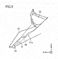
- Fig. 5 schematically illustrates a sensing area of sensor 40. As illustrated in Fig. 5 , sensor 40 is disposed such that an optical axis 48 of sensor 40 extends along boom 31.
- Sensor 40 senses an area covering lower end 31a of boom 31.
- Sensor 40 may sense an area closer to the distal end of boom 31 than to the proximal end of boom 31, in lower end 31a of boom 31.
- sensor 40 senses an area ranging from the position of the second end of each lift cylinder 33 mounted to boom 31 to the distal end of boom 31, in lower end 31a of boom 31.
- sensor 40 may sense a part of each area described above.
- Sensor 40 disposed as described above measures a distance between boom 31 and the dump truck as the loading target.
- Information acquired by sensor 40 is sent to a controller 110 ( Fig. 8 ) of wheel loader 1 and then is subjected to data processing in controller 110 as will be described later.
- Fig. 6 illustrates a typical operation by the operator in dump approach.
- the operator initiates acceleration in a section Q11.
- the operator presses an accelerator pedal (not illustrated)
- the operator actuates a boom control lever 122 ( Fig. 8 ) to raise boom 31 as will be described later.
- wheel loader 1 thus travels toward dump truck 900 while performing boom-raising
- the operator initiates acceleration in section Q11 for the purpose of supplying a satisfactory amount of oil to lift cylinders 33, rather than for the purpose of causing wheel loader 1 to travel.
- Increasing an engine speed ensures an output of hydraulic oil from the hydraulic pump. Accordingly, the operator still presses the accelerator pedal even when he or she presses a brake pedal to decrease a vehicle speed in section Q11.
- a section Q12 subsequent to section Q11 the operator ceases the acceleration and then initiates braking. Specifically, the operator presses the brake pedal (not illustrated) instead of the accelerator pedal. The operator thus brings wheel loader 1 to a stop in front of dump truck 900. Thereafter, the operator actuates a bucket control lever 123 ( Fig. 8 ) to load soil scooped by bucket 32 onto a bed of dump truck 900 as will be described later.
- a broken line La represents a path along which bucket 32 typically moves in the series of operations.
- Figs. 7(A) and 7(B) each illustrate a situation in which the operator does not raise boom 31 to a position where an excavated object is loadable onto vessel 901 of dump truck 900, in the dump approach.
- Fig. 7(A) illustrates the dump approach on the assumption that an output from sensor 40 is not utilized.
- Fig. 7(B) illustrates the dump approach on the assumption that an output from sensor 40 is utilized.
- Fig. 7(A) illustrates a comparative example for clarifying a feature of the damp approach in Fig. 7(B) .
- a broken line Lb represents a path of bucket 32.
- wheel loader 1 (specifically, controller 110) controls boom-raising as illustrated in Fig. 7(B) .
- Wheel loader 1 determines whether distance D to be measured by sensor 40 (i.e., the distance between boom 31 and dump truck 900) takes a value less than or equal to a threshold value. When wheel loader 1 determines that the value of distance D measured is less than or equal to the threshold value, then wheel loader 1 starts to raise boom 31. For example, wheel loader 1 does not raise boom 31 in a section Q21 during which the value of distance D measured is larger than the threshold value. When wheel loader 1 arrives at a section Q22 during which the value of distance D measured is less than or equal to the threshold value, then wheel loader 1 starts to raise boom 31.
- wheel loader 1 includes sensor 40 configured to measure distance D between boom 31 and dump truck 900. Controller 110 of wheel loader 1 causes wheel loader 1 to perform boom-raising on condition that distance D to be measured by sensor 40 when wheel loader 1 travels takes a value less than or equal to the threshold value.
- wheel loader 1 moves boom 31 away from vessel 901 before collision of boom 31 with vessel 901 in the dump approach. Wheel loader 1 accordingly avoids the collision of boom 31 with dump truck 900 even when the operator neglects to confirm the position of boom 31 because he or she pays excessive attention to the position of each front wheel 3a. Wheel loader 1 therefore assists the operation by the operator in the dump approach.
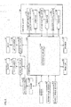
- Fig. 8 is a block diagram of a system configuration of wheel loader 1.
- wheel loader 1 includes boom 31, bucket 32, lift cylinders 33, tilt cylinder 35, sensor 40, controller 110, a boom angle sensor 112, a bucket angle sensor 113, an engine 118, hydraulic pump 119, a control lever 120, control valves 131 and 141, a monitor 151, and a speaker 152.
- Control lever 120 includes a fore/aft traveling switch control lever 121, boom control lever 122, bucket control lever 123, and vibrators 124, 125, and 126.
- Controller 110 includes a determination unit 1101.
- Controller 110 controls the overall actions of wheel loader 1. Controller 110 controls, for example, a rotation speed of engine 118, based on the actuation of the accelerator pedal. In addition, the controller receives a signal based on the actuation of control lever 120 by the operator, and then causes wheel loader 1 to perform an action in accordance with the actuation.
- Hydraulic pump 119 is driven by an output from engine 118. Hydraulic pump 119 supplies the hydraulic oil to lift cylinders 33 via control valve 131 such that boom 31 is driven. Boom 31 is raised or lowered by actuation of boom control lever 122 in operator's cab 6. Hydraulic pump 119 also supplies the hydraulic oil to tilt cylinder 35 via control valve 141 such that bucket 32 is driven. Bucket 32 is acted by actuation of bucket control lever 123 in operator's cab 6.
- Controller 110 successively receives results of sensing from sensor 40.
- determination unit 1101 of controller 110 determines whether distance D to be measured by sensor 40 takes a value less than or equal to threshold value Th.
- controller 110 starts to raise boom 31.
- Controller 110 receives a signal according to a boom angle from boom angle sensor 112. Controller 110 also receives a signal according to a tilt angle from bucket angle sensor 113. A description will be given of how to utilize signals (results of sensing) output from boom angle sensor 112 and bucket angle sensor 113, later.
- Controller 110 causes monitor 151 to display various images. Controller 110 causes speaker 152 to output a predetermined sound. A description will be given of how to utilize monitor 151 and speaker 152, later.
- Vibrator 124 is configured to vibrate fore/aft traveling switch control lever 121.
- Vibrator 125 is configured to vibrate boom control lever 122.
- Vibrator 126 is configured to vibrate bucket control lever 123. A description will be given of how to utilize vibrators 124 to 126, later.
- Fig. 9 is a flowchart of a processing flow in wheel loader 1.
- controller 110 determines whether wheel loader 1 is traveling forward.
- controller 110 determines whether distance D measured by sensor 40 takes a value less than or equal to threshold value Th.
- controller 110 determines that wheel loader 1 is not traveling forward (NO in step S2), the processing goes back to step S2.
- controller 110 determines that the value of distance D is less than or equal to threshold value Th (YES in step S4), then, in step S6, controller 110 starts to raise boom 31.
- controller 110 determines that the value of distance D is larger than threshold value Th (NO in step S4), the processing goes back to step S2.
- controller 110 determines whether distance D measured by sensor 40 takes a value less than or equal to threshold value Th.
- step S14 controller 110 stops boom 31 being raised.
- step S16 controller 110 determines whether wheel loader 1 is traveling forward.
- controller 110 determines that wheel loader 1 is traveling forward (YES in step S16)
- the processing goes back to step S4.
- controller 110 determines that wheel loader 1 is not traveling forward (NO in step S16)
- controller 110 determines whether an angle (a boom angle) of boom 31 is maximum. Specifically, controller 110 determines whether each of lift cylinders 33 has extended to its stroke end.
- controller 110 determines that the boom angle is maximum (YES in step S10), then, in step S12, controller 110 brings wheel loader 1 to a stop. Typically, controller 110 initiates braking even when the operator does not press the braking pedal. When controller 110 determines that the boom angle is not maximum (NO in step S10), the processing goes to step S8.
- controller 110 causes wheel loader 1 to raise boom 31 on condition that distance D takes a value less than or equal to threshold value Th.
- Wheel loader 1 may be configured to allow the operator to forcibly cease the control by controller 110. Examples of such an operation by the operator may include an operation to press down a predetermined button (not illustrated), an operation to actuate boom control lever 122 to lower boom 31, and an operation to shift fore/aft traveling switch control lever 121 from a fore traveling position to an aft traveling position. In wheel loader 1, the operator performs the operation to shift fore/aft traveling switch control lever 121 from the fore traveling position to the aft traveling position even when wheel loader 1 is traveling forward (i.e., is not stopping).
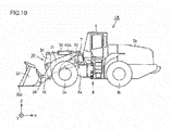
- Fig. 10 is a side view of wheel loader 1A according to the second embodiment.
- Fig. 11 is a top view of wheel loader 1A.
- Fig. 12 is a perspective view of wheel loader 1A.
- wheel loader 1A has a hardware configuration similar to the hardware configuration of wheel loader 1A, except for a sensor 40A provided instead of sensor 40.
- Sensor 40A is disposed on an upper face of a front frame 5a. Sensor 40A is disposed at a predetermined position that is closer to a position where a boom 31 is supported than to a front end 51 (see Fig. 13 ) of front frame 5a. Specifically, sensor 40A is disposed closer to a boom pin 7 than to the front end of front frame 5a.
- Sensor 40A is disposed between a position where left boom 31 is supported and a position where a tilt cylinder 35 is supported, as seen in top view in a Y direction illustrated in Fig 11 .
- Sensor 40A may be disposed between a position where right boom 31 is supported and the position where tilt cylinder 35 is supported, as seen in top view.
- Sensor 40A measures a distance D between boom 31 and dump truck 900 in dump approach, as in a manner similar to that of sensor 40. Specifically, sensor 40A measures distance D between boom 31 and vessel 901 of dump truck 900, as in a manner similar to that of sensor 40. Sensor 40A senses a lower end of boom 31 with boom 31 raised, as in a manner similar to that of sensor 40. Sensor 40A may be any device for measuring distance D. Examples of sensor 40A may include various devices such as an ultrasonic sensor, a laser sensor, an infrared sensor, and a camera.
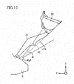
- Fig. 13 schematically illustrates a sensing area of sensor 40A.
- sensor 40A is disposed such that an optical axis 49 of sensor 40A approximately extends along boom 31 with boom 31 raised at an angle greater than or equal to a predetermined angle.
- the sensing area of sensor 40A is set in advance with a boom angle in the dump approach taken into consideration.
- Sensor 40A senses an area covering a lower end 31a of boom 31.
- Sensor 40A may sense an area closer to a distal end of boom 31 than to a proximal end of boom 31, in lower end 31a of boom 31.
- sensor 40A senses an area ranging from a position of a second end of each lift cylinder 33 mounted to boom 31 to the distal end of boom 31, in lower end 31a of boom 31.
- sensor 40A may sense a part of each area described above.
- Sensor 40A disposed as described above measures distance D between boom 31 and the dump truck as the loading target.
- Information acquired by sensor 40A is sent to a controller 110 of wheel loader 1A and then is subjected to data processing in controller 110.
- Controller 110 of wheel loader 1A operates like controller 110 of wheel loader 1. Specifically, controller 110 causes wheel loader 1 to perform a predetermined action for collision avoidance, that is, an action to raise boom 31 on condition that distance D to be measured by sensor 40A when wheel loader 1A travels takes a value less than or equal to a threshold value Th.
- a predetermined action for collision avoidance that is, an action to raise boom 31 on condition that distance D to be measured by sensor 40A when wheel loader 1A travels takes a value less than or equal to a threshold value Th.
- wheel loader 1A moves boom 31 away from vessel 901 before collision of boom 31 with vessel 901 in the dump approach.
- Wheel loader 1A therefore avoids the collision of boom 31 with dump truck 900 even when the operator neglects to confirm the position of boom 31 because he or she operates wheel loader 1A while directing his or her line of sight to front wheels 3a.
- controller 110 causes wheel loader 1 to perform the predetermined action, that is, the action to raise boom 31 on condition that distance D to be measured by sensor 40A when wheel loader 1A travels takes a value less than or equal to threshold value Th.
- the predetermined action is not limited to the action to raise boom 31.
- Controller 110 may cause speaker 152 to output a predetermined audible notification (audible alarm), in place of the control for raising boom 31.
- controller 110 may cause monitor 151 to display a predetermined warning.
- Controller 110 may send a command to each of vibrators 124 to 126 such that vibrators 124 to 126 start to vibrate.
- the vibrations of vibrators 124, 125, and 126 vibrate corresponding control levers 121, 122, and 123. This configuration also makes the operator aware of an abnormal state.
- Wheel loader 1, 1A may be configured to perform the action to raise boom 31, the output of the predetermined audible alarm from speaker 152, the display of the predetermined warning on monitor 151, and the vibrations of vibrators 124 to 126 in appropriate combination.
- Fig. 14 illustrates a tilt angle ⁇ of bucket 32. It should be noted that Fig. 14 illustrates wheel loader 1. As illustrated in Fig. 14 , since an excavated object such as soil is loaded on bucket 32 in the dump approach, the operator needs to set tilt angle ⁇ to be larger than a predetermined angle (hereinafter, also referred to as "angle ⁇ 1").
- wheel loader 1, 1A is not configured to always perform the predetermined action on condition that distance D takes a value less than or equal to threshold value Th, but may be configured to perform the predetermined action on condition that the tilt angle of bucket 32 is greater than or equal to predetermined angle ⁇ 1.
- wheel loader 1, 1A performs the predetermined action on condition that distance D takes a value less than or equal to threshold value Th.
- wheel loader 1, 1A does not perform the predetermined action on condition that the value of distance D is less than or equal to threshold value Th.
- wheel loader 1, 1A approaching dump truck 900 does not perform the predetermined action on condition that no excavated object is loaded on bucket 32.
- Fig. 15 illustrates how to level off an excavated object. It should be noted that Fig. 15 illustrates wheel loader 1. As illustrated in Fig. 15 , when the operator operates wheel loader 1 to load an excavated object onto vessel 901 of dump truck 900, the excavated object can be heaped on vessel 901 beyond the height of vessel 901. In such a case, the operator sets the tilt angle of bucket 32 to be less than or equal to a predetermined angle (hereinafter, referred to as "angle ⁇ 2") that is smaller than angle ⁇ 1. The operator then operates bucket 32 to drop the excavated object heaped beyond the upper side of vessel 901.
- angle ⁇ 2 a predetermined angle
- tilt angle ⁇ of bucket 32 is set at zero (i.e., a state in which a cutting edge 32a is horizontal to main body 5), and then the soil heaped beyond the upper side of vessel 901 is dropped onto the ground opposite from wheel loader 1, 1A across dump truck 900.
- controller 110 causes wheel loader 1 to stop the predetermined action, that is, boom-raising on condition that tilt angle ⁇ is less than or equal to angle ⁇ 2 that is smaller than angle ⁇ 1. This configuration allows the operator to level off the excavated object.
- controller 110 may be configured to cause wheel loader 1, 1A to stop the predetermined action after a transition of wheel loader 1, 1A from a fore traveling state to an aft traveling state. This configuration avoids execution of unnecessary control.
- a wheel loader for loading an excavated object onto a loading target includes: a front frame; a bucket; a boom having a distal end connected to the bucket, and a proximal end rotatably supported by the front frame; a sensor configured to measure a distance between the boom and the loading target, and a controller configured to control an action of the wheel loader.
- the controller causes the wheel loader to perform a predetermined action for collision avoidance on condition that a distance to be measured by the sensor when the wheel loader travels takes a value less than or equal to a threshold value
- the wheel loader traveling forward performs the predetermined action for collision avoidance before collision of the boom with the loading target.
- the wheel loader therefore avoids the collision of the boom with the loading target even when an operator neglects to confirm a position of the boom.
- the wheel loader thus assists an operation by the operator in loading the excavated object onto the loading target.
- the senor is disposed at one of a first position in the boom, the first position being closer to the proximal end of the boom than to the distal end of the boom, and a second position in the front frame, the second position being closer to a position where the boom is supported than to a front end of the front frame.
- the first position corresponds to a lower end of the boom.
- This configuration allows the sensor of the wheel loader to sense the lower end of the boom.
- the senor is disposed at the first position and is configured to sense an area covering a lower end of the boom, the area being closer to the distal end of the boom than to the proximal end of the boom.
- This configuration allows the wheel loader to measure the distance between the boom and the loading target.
- the wheel loader further includes a lift cylinder having one end mounted to a lower end of the boom, the lift cylinder being configured to drive the boom.
- the sensor is disposed at the first position and is configured to sense an area ranging from a position of the lift cylinder mounted to the boom to the distal end of the boom, in the lower end of the boom.
- This configuration allows the wheel loader to measure the distance between the boom and the loading target.
- the predetermined action corresponds to an action to raise the boom.
- This configuration allows the wheel loader traveling forward to move the boom away from the loading target before collision of the boom with the loading target. This configuration therefore allows the wheel loader to avoid the collision of the boom with the loading target even when the operator neglects to confirm the position of the boom.
- the predetermined action corresponds to an action to output a predetermined audible notification.
- This configuration allows the operator to perform an operation to avoid collision of the boom with the loading target in such a manner that the operator listens to the audible notification before the collision of the boom with the loading target.
- the wheel loader further includes a control lever configured to operate the wheel loader.
- the predetermined action corresponds to an action to vibrate the control lever
- This configuration allows the operator to perform the operation to avoid collision of the boom with the loading target in such a manner that the operator feels the vibration of the control lever before the collision of the boom with the loading target.
- the controller brings the wheel loader to a stop on condition that the boom is raised at a maximum angle by the predetermined action.
- This configuration prevents collision of the boom with the loading target in a situation in which the boom collides with the loading target even when the boom is retreated as much as possible.
- the controller causes the wheel loader to perform the predetermined action on condition that a tilt angle of the bucket takes a value greater than or equal to a first value.
- This configuration prevents the wheel loader approaching the loading target from performing the predetermined action for collision avoidance on condition that no excavated object is loaded on the bucket.
- the predetermined action corresponds to an action to raise the boom.
- the controller causes the wheel loader to stop the action to raise the boom on condition that the tilt angle takes a value less than or equal to a second value that is smaller than the first value.
- the controller causes the wheel loader to stop the predetermined action on condition that the controller receives a predetermined input based on an operation by the operator.
- the operator forcibly stops the control for raising the boom on condition that the distance between the boom and the loading target takes a value less than or equal to the threshold value.
- the predetermined action corresponds to an action to raise the boom.
- the operation by the operator corresponds to an operation to lower the boom.
- the wheel loader further includes a fore/aft traveling switch lever configured to switch between fore traveling of the wheel loader and aft traveling of the wheel loader.
- the operation by the operator corresponds to an operation to shift the fore/aft traveling switch lever from a fore traveling position to an aft traveling position.
- the fore/aft traveling switch lever switching operation allows a forcible stop of the control for raising the boom on condition that the distance between the boom and the loading target takes a value less than or equal to the threshold value.
- the controller causes the wheel loader to stop the predetermined action after a transition of the wheel loader from a fore traveling state to an aft traveling state.
- the controller causes the wheel loader in the aft traveling state to stop the action to raise the boom on condition that the distance between the boom and the loading target takes a value less than or equal to the threshold value.
- a method for controlling a wheel loader configured to load an excavated object onto a loading target includes the steps of: measuring a distance between a boom of the wheel loader and the loading target; determining that the distance measured takes a value less than or equal to a threshold value when the wheel loader travels, and causing the wheel loader to perform a predetermined action for collision avoidance on condition that the value of the distance measured is less than or equal to the threshold value.
- the wheel loader traveling forward performs the predetermined action for collision avoidance before collision of the boom with the loading target.
- the wheel loader therefore avoids the collision of the boom with the loading target even when the operator neglects to confirm the position of the boom.
- the wheel loader thus assists an operation by the operator in loading the excavated object onto the loading target.
Landscapes
- Engineering & Computer Science (AREA)
- Mining & Mineral Resources (AREA)
- Civil Engineering (AREA)
- General Engineering & Computer Science (AREA)
- Structural Engineering (AREA)
- Mechanical Engineering (AREA)
- Physics & Mathematics (AREA)
- Acoustics & Sound (AREA)
- Human Computer Interaction (AREA)
- Operation Control Of Excavators (AREA)
- Component Parts Of Construction Machinery (AREA)
Description
- The present invention relates to a wheel loader and a method for controlling the wheel loader.
- A wheel loader that is an example of self-propelled work vehicles includes a traveling apparatus that causes the vehicle to travel, and a work implement that performs various operations/services including excavation. The traveling apparatus and the work implement are each driven by driving force from an engine.
- Japanese Patent Laying-Open No.
2008-303574 - Japanese Patent Laying-Open No.
10-88625 - An operator of a wheel loader simultaneously actuates an accelerator pedal and a boom lever to load, on a bed of a dump truck, soil scooped by a bucket of a work implement. The wheel loader thus simultaneously performs fore traveling and boom-raising. Such a loading operation/service is also called "dump approach".
-
- PTL 1: Japanese Patent Laying-Open No.
2008-303574 - PTL 2: Japanese Patent Laying-Open No.
10-88625 - Further prior art is known from document
JP 2008 144378 A - In a loading operation/service, an operator needs to operate a wheel loader so as to prevent a leading end of a front wheel from colliding with a lateral side of a dump truck and so as to prevent a work implement (particularly, a lower end of a boom) from colliding with the lateral side of the dump truck (specifically, an upper portion of a vessel). As described above, the operator needs to implement the loading operation/service while checking on the upper and lower locations at the same time.
- The present disclosure has been made in view of the problem described above. The present disclosure provides a wheel loader that assists an operation by an operator in loading an excavated object such as excavated soil onto a loading target (e.g., a dump truck). The present disclosure also provides a method for controlling the wheel loader.
- The object is solved by the subject matter of
claims 1 and 15. - A wheel loader according to an aspect of the present disclosure assists an operation by an operator in loading an excavated object onto a loading target.
-
-
Fig. 1 is a side view of a wheel loader. -
Fig. 2 is a top view of the wheel loader. -
Fig. 3 is a perspective view of the wheel loader. -
Figs. 4(A) and 4(B) each illustrate a positional relationship between a left boom and a sensor. -
Fig. 5 schematically illustrates a sensing area of the sensor. -
Fig. 6 illustrates a typical operation by an operator in dump approach. -
Figs. 7(A) and 7(B) each illustrate a situation in which the operator does not raise the boom to a position where an excavated object is loadable onto a vessel of a dump truck, in the dump approach. -
Fig. 8 is a block diagram of a system configuration of the wheel loader. -
Fig. 9 is a flowchart of a processing flow in the wheel loader. -
Fig. 10 is a side view of a wheel loader. -
Fig. 11 is a top view of the wheel loader. -
Fig. 12 is a perspective view of the wheel loader. -
Fig. 13 schematically illustrates a sensing area of a sensor. -
Fig. 14 illustrates a tilt angle of a bucket. -
Fig. 15 illustrates how to level off an excavated object. - Embodiments will be described below with reference to the drawings. It is originally planned to utilize configurations of the embodiments in appropriate combination. In addition, some of constituent elements are not employed occasionally.
- A description will be given of a wheel loader with reference to the drawings. In the following description, the terms "upper", "lower", "front", "rear", "left", and "right" are defined with respect to an operator who sits in an operator's seat.
- A dump truck will be described as an example of a loading target onto which an excavated object is loaded; however, the loading target is not limited thereto, but may be a non-self-propelled loading target such as a soil container.
-
Fig. 1 is a side view of awheel loader 1 according to a first embodiment,Fig. 2 is a top view ofwheel loader 1. - As illustrated in
Figs. 1 and2 ,wheel loader 1 includes amain body 5, a work implement 30,wheels cab 6.Wheel loader 1 is self-propelled in such a manner thatwheels wheel loader 1 performs desired operations/services using work implement 30. -
Main body 5 includes afront frame 5a and arear frame 5b.Front frame 5a andrear frame 5b are connected to each other by acenter pin 81 so as to be swingable laterally. -
Steering cylinders 82 are provided in a pair so as to extend fromfront frame 5a torear frame 5b. Eachsteering cylinder 82 is a hydraulic cylinder to be driven by hydraulic oil from a steering pump (not illustrated).Front frame 5a swings relative torear frame 5b by expansion and contraction ofsteering cylinders 82. This action changes a traveling direction ofwheel loader 1. - Work implement 30 and a pair of
front wheels 3a are mounted tofront frame 5a.Work implement 30 is disposed forward ofmain body 5.Work implement 30 is driven by hydraulic oil from a hydraulic pump 119 (seeFig. 3 ).Work implement 30 includes aboom 31, a pair oflift cylinders 33, abucket 32, abell crank 34, atilt cylinder 35, and atilt rod 36 connecting a distal end ofbell crank 34 tobucket 32. -
Boom 31 is rotatably supported byfront frame 5a.Boom 31 has a proximal end (proximal end) mounted tofront frame 5a by aboom pin 7 such thatboom 31 is swingable. Eachlift cylinder 33 has a first end mounted tofront frame 5a. Eachlift cylinder 33 has a second end mounted to boom 31. Preferably, the second end of eachlift cylinder 33 is mounted to a lower end ofboom 31.Front frame 5a andboom 31 are connected to each other bylift cylinders 33.Boom 31 swings upward and downward aboutboom pin 7 by expansion and contraction oflift cylinders 33 using the hydraulic oil fromhydraulic pump 119. -
Fig. 1 illustrates only one oflift cylinders 33. -
Bucket 32 is rotatably supported by a leading end ofboom 31.Bucket 32 is swingably directed to a distal end ofboom 31 by abucket pin 39.Tilt cylinder 35 has a first end mounted tofront frame 5a.Tilt cylinder 35 has a second end mounted to bell crank 34. Bell crank 34 andbucket 32 are connected to each other by a link apparatus (not illustrated).Front frame 5a andbucket 32 are connected to each other bytilt cylinder 35, bell crank 34, and the link apparatus.Bucket 32 swings upward and downward aboutbucket pin 39 by expansion and contraction oftilt cylinder 35 using the hydraulic oil fromhydraulic pump 119. - Operator's
cab 6 and a pair ofrear wheels 3b are mounted torear frame 5b. Operator'scab 6 is mounted onmain body 5. Operator'scab 6 includes, for example, a seat in which an operator sits, and devices for operations (to be described later). -
Wheel loader 1 further includes asensor 40 configured to measure a distance betweenboom 31 and a dump truck as a loading target.Sensor 40 is disposed onboom 31.Sensor 40 therefore moves together withboom 31. - Specifically,
sensor 40 is disposed at a predetermined position inboom 31. The predetermined position is closer to the proximal end ofboom 31 than to the distal end ofboom 31.Sensor 40 is disposed on the lower end ofboom 31.Sensor 40 is disposed nearboom pin 7. As used herein, the phrase "lower end ofboom 31" refers to the lower (ground side) half ofboom 31, including a lower face ofboom 31. - As will be described later,
sensor 40 measures a distance (hereinafter, also referred to as "distance D") betweenboom 31 and a vessel of the dump truck.Sensor 40 senses the lower end ofboom 31.Sensor 40 may be any device for measuring a distance. Examples ofsensor 40 may include various devices such as an ultrasonic sensor, a laser sensor, an infrared sensor, and a camera. -
Fig 3 is a perspective view ofwheel loader 1. As illustrated inFig. 3 ,boom 31 is raised based on an operation by the operator, so thatbucket 32 is also raised, The operator decreases a tilt angle (angle θ inFig. 14 ) ofbucket 32 with an excavated object such as excavated soil loaded on the bucket. The excavated object is thus loaded onto the loading target such as the dump truck. -
Figs. 4(A) and 4(B) each illustrate a positional relationship betweenleft boom 31 andsensor 40. As illustrated inFigs. 4(A) and 4(B) ,sensor 40 is disposed onlower end 31a ofboom 31.Sensor 40 includes a housing, and alens 41 disposed in the housing at a position near the distal end ofboom 31. - In
wheel loader 1,lens 41 is disposed on the right side of left boom 31 (i.e., is disposed onleft boom 31 at a position near right boom 31); however, the present disclosure is not limited to this configuration. For example,lens 41 may be disposed on the left side ofleft boom 31. Alternatively, the sensor may be disposed onright boom 31. -
Fig. 5 schematically illustrates a sensing area ofsensor 40. As illustrated inFig. 5 ,sensor 40 is disposed such that anoptical axis 48 ofsensor 40 extends alongboom 31. -
Sensor 40 senses an area coveringlower end 31a ofboom 31.Sensor 40 may sense an area closer to the distal end ofboom 31 than to the proximal end ofboom 31, inlower end 31a ofboom 31. Preferably,sensor 40 senses an area ranging from the position of the second end of eachlift cylinder 33 mounted to boom 31 to the distal end ofboom 31, inlower end 31a ofboom 31. Alternatively,sensor 40 may sense a part of each area described above. -
Sensor 40 disposed as described above measures a distance betweenboom 31 and the dump truck as the loading target. Information acquired bysensor 40 is sent to a controller 110 (Fig. 8 ) ofwheel loader 1 and then is subjected to data processing incontroller 110 as will be described later. -
Fig. 6 illustrates a typical operation by the operator in dump approach. As illustrated inFig. 6 , the operator initiates acceleration in a section Q11. Specifically, the operator presses an accelerator pedal (not illustrated) Also in section Q11, the operator actuates a boom control lever 122 (Fig. 8 ) to raiseboom 31 as will be described later. In section Q11,wheel loader 1 thus travels towarddump truck 900 while performing boom-raising - The operator initiates acceleration in section Q11 for the purpose of supplying a satisfactory amount of oil to lift
cylinders 33, rather than for the purpose of causingwheel loader 1 to travel. Increasing an engine speed ensures an output of hydraulic oil from the hydraulic pump. Accordingly, the operator still presses the accelerator pedal even when he or she presses a brake pedal to decrease a vehicle speed in section Q11. - In a section Q12 subsequent to section Q11, the operator ceases the acceleration and then initiates braking. Specifically, the operator presses the brake pedal (not illustrated) instead of the accelerator pedal. The operator thus brings
wheel loader 1 to a stop in front ofdump truck 900. Thereafter, the operator actuates a bucket control lever 123 (Fig. 8 ) to load soil scooped bybucket 32 onto a bed ofdump truck 900 as will be described later. - A broken line La represents a path along which
bucket 32 typically moves in the series of operations. -
Figs. 7(A) and 7(B) each illustrate a situation in which the operator does not raiseboom 31 to a position where an excavated object is loadable ontovessel 901 ofdump truck 900, in the dump approach.Fig. 7(A) illustrates the dump approach on the assumption that an output fromsensor 40 is not utilized.Fig. 7(B) illustrates the dump approach on the assumption that an output fromsensor 40 is utilized.Fig. 7(A) illustrates a comparative example for clarifying a feature of the damp approach inFig. 7(B) . - As illustrated in
Fig. 7(A) , if the operator does not raiseboom 31 to a height illustrated inFig. 6 in section Q11, the following event can occur in section Q12. In order to avoid a leading end of eachfront wheel 3a inwheel loader 1 from colliding with a lateral side ofdump truck 900, the operator causeswheel loader 1 to travel forward while seeingfront wheels 3a. As a result, the lower end ofboom 31 collides with an upper portion ofvessel 901 ofdump truck 900 before eachfront wheel 3a arrives at a position where the operator intends to stopwheel loader 1. According to this embodiment, the use ofsensor 40 enables avoidance of this event. With reference toFig. 7(B) , a description will be given of how to avoid this event. InFig. 7(A) , a broken line Lb represents a path ofbucket 32. - If the operator does not raise
boom 31 to the height illustrated inFig. 6 in section Q11, wheel loader 1 (specifically, controller 110) controls boom-raising as illustrated inFig. 7(B) . -
Wheel loader 1 determines whether distance D to be measured by sensor 40 (i.e., the distance betweenboom 31 and dump truck 900) takes a value less than or equal to a threshold value. Whenwheel loader 1 determines that the value of distance D measured is less than or equal to the threshold value, thenwheel loader 1 starts to raiseboom 31. For example,wheel loader 1 does not raiseboom 31 in a section Q21 during which the value of distance D measured is larger than the threshold value. Whenwheel loader 1 arrives at a section Q22 during which the value of distance D measured is less than or equal to the threshold value, thenwheel loader 1 starts to raiseboom 31. - As described above,
wheel loader 1 includessensor 40 configured to measure distance D betweenboom 31 anddump truck 900.Controller 110 ofwheel loader 1 causeswheel loader 1 to perform boom-raising on condition that distance D to be measured bysensor 40 whenwheel loader 1 travels takes a value less than or equal to the threshold value. - As described above,
wheel loader 1moves boom 31 away fromvessel 901 before collision ofboom 31 withvessel 901 in the dump approach.Wheel loader 1 accordingly avoids the collision ofboom 31 withdump truck 900 even when the operator neglects to confirm the position ofboom 31 because he or she pays excessive attention to the position of eachfront wheel 3a.Wheel loader 1 therefore assists the operation by the operator in the dump approach. -
Fig. 8 is a block diagram of a system configuration ofwheel loader 1. As illustrated inFig. 8 ,wheel loader 1 includesboom 31,bucket 32,lift cylinders 33,tilt cylinder 35,sensor 40,controller 110, aboom angle sensor 112, abucket angle sensor 113, anengine 118,hydraulic pump 119, acontrol lever 120,control valves monitor 151, and aspeaker 152. -
Control lever 120 includes a fore/aft travelingswitch control lever 121,boom control lever 122,bucket control lever 123, andvibrators Controller 110 includes adetermination unit 1101. -
Controller 110 controls the overall actions ofwheel loader 1.Controller 110 controls, for example, a rotation speed ofengine 118, based on the actuation of the accelerator pedal. In addition, the controller receives a signal based on the actuation ofcontrol lever 120 by the operator, and then causeswheel loader 1 to perform an action in accordance with the actuation. -
Hydraulic pump 119 is driven by an output fromengine 118.Hydraulic pump 119 supplies the hydraulic oil to liftcylinders 33 viacontrol valve 131 such thatboom 31 is driven.Boom 31 is raised or lowered by actuation ofboom control lever 122 in operator'scab 6.Hydraulic pump 119 also supplies the hydraulic oil to tiltcylinder 35 viacontrol valve 141 such thatbucket 32 is driven.Bucket 32 is acted by actuation ofbucket control lever 123 in operator'scab 6. -
Controller 110 successively receives results of sensing fromsensor 40. In the dump approach,determination unit 1101 ofcontroller 110 determines whether distance D to be measured bysensor 40 takes a value less than or equal to threshold value Th. Whendetermination unit 1101 determines that the value of distance D is less than or equal to threshold value Th,controller 110 starts to raiseboom 31. -
Controller 110 receives a signal according to a boom angle fromboom angle sensor 112.Controller 110 also receives a signal according to a tilt angle frombucket angle sensor 113. A description will be given of how to utilize signals (results of sensing) output fromboom angle sensor 112 andbucket angle sensor 113, later. -
Controller 110 causes monitor 151 to display various images.Controller 110 causesspeaker 152 to output a predetermined sound. A description will be given of how to utilizemonitor 151 andspeaker 152, later. -
Vibrator 124 is configured to vibrate fore/aft travelingswitch control lever 121.Vibrator 125 is configured to vibrateboom control lever 122.Vibrator 126 is configured to vibratebucket control lever 123. A description will be given of how to utilizevibrators 124 to 126, later. -
Fig. 9 is a flowchart of a processing flow inwheel loader 1. As illustrated inFig. 9 , in step S2,controller 110 determines whetherwheel loader 1 is traveling forward. Whencontroller 110 determines thatwheel loader 1 is traveling forward (YES in step S2), then, in step S4,controller 110 determines whether distance D measured bysensor 40 takes a value less than or equal to threshold value Th. Whencontroller 110 determines thatwheel loader 1 is not traveling forward (NO in step S2), the processing goes back to step S2. - When
controller 110 determines that the value of distance D is less than or equal to threshold value Th (YES in step S4), then, in step S6,controller 110 starts to raiseboom 31. Whencontroller 110 determines that the value of distance D is larger than threshold value Th (NO in step S4), the processing goes back to step S2. In step S8,controller 110 determines whether distance D measured bysensor 40 takes a value less than or equal to threshold value Th. - When
controller 110 determines that the value of distance D is larger than threshold value Th (YES in step S8), then, in step S14,controller 110stops boom 31 being raised. In step S16 subsequent to step S14,controller 110 determines whetherwheel loader 1 is traveling forward. Whencontroller 110 determines thatwheel loader 1 is traveling forward (YES in step S16), the processing goes back to step S4. Whencontroller 110 determines thatwheel loader 1 is not traveling forward (NO in step S16), the processing ends. - When
controller 110 determines that the value of distance D is less than or equal to threshold value Th (NO in step S8), then, in step S10,controller 110 determines whether an angle (a boom angle) ofboom 31 is maximum. Specifically,controller 110 determines whether each oflift cylinders 33 has extended to its stroke end. - When
controller 110 determines that the boom angle is maximum (YES in step S10), then, in step S12,controller 110 bringswheel loader 1 to a stop. Typically,controller 110 initiates braking even when the operator does not press the braking pedal. Whencontroller 110 determines that the boom angle is not maximum (NO in step S10), the processing goes to step S8. - As described above,
controller 110 causeswheel loader 1 to raiseboom 31 on condition that distance D takes a value less than or equal to threshold value Th.Wheel loader 1 may be configured to allow the operator to forcibly cease the control bycontroller 110. Examples of such an operation by the operator may include an operation to press down a predetermined button (not illustrated), an operation to actuateboom control lever 122 tolower boom 31, and an operation to shift fore/aft travelingswitch control lever 121 from a fore traveling position to an aft traveling position. Inwheel loader 1, the operator performs the operation to shift fore/aft travelingswitch control lever 121 from the fore traveling position to the aft traveling position even whenwheel loader 1 is traveling forward (i.e., is not stopping). -
- (1) As described above,
sensor 40 is disposed at the predetermined position inboom 31. The predetermined position is closer to the proximal end ofboom 31 than to the distal end ofboom 31.Controller 110 causeswheel loader 1 to perform the predetermined action for collision avoidance, that is, the action to raiseboom 31 on condition that distance D to be measured bysensor 40 whenwheel loader 1 travels takes a value less than or equal to threshold value Th.
With this configuration,wheel loader 1moves boom 31 away fromvessel 901 as shown with section Q22 inFig. 7(B) before collision ofboom 31 withvessel 901 in the dump approach.Wheel loader 1 therefore avoids the collision ofboom 31 withdump truck 900 even when the operator neglects to confirm the position ofboom 31.Wheel loader 1 thus assists the operation by the operator in the dump approach. - (2) Specifically, the predetermined position corresponds to
lower end 31a ofboom 31. This configuration enables sensing onlower end 31a ofboom 31. - (3)
Sensor 40 senseslower end 31a ofboom 31 This configuration enables measurement of distance D betweenboom 31 andvessel 901 ofdump truck 900. - (4)
Controller 110 bringswheel loader 1 to a stop on condition that the angle ofboom 31 is maximum. This configuration prevents collision ofboom 31 withvessel 901 in a situation in which boom 31 collides withvessel 901 even whenboom 31 is retreated as much as possible. - A description will be given of a wheel loader according to a second embodiment with reference to the drawings. It should be noted that a description will be given of different configurations of the wheel loader according to the second embodiment from those of
wheel loader 1 according to the first embodiment; therefore, no description will be given of similar configurations of the wheel loader according to the second embodiment to those ofwheel loader 1 according to the first embodiment. -
Fig. 10 is a side view ofwheel loader 1A according to the second embodiment.Fig. 11 is a top view ofwheel loader 1A.Fig. 12 is a perspective view ofwheel loader 1A. - As illustrated in
Figs. 10 ,11 , and12 ,wheel loader 1A has a hardware configuration similar to the hardware configuration ofwheel loader 1A, except for asensor 40A provided instead ofsensor 40. -
Sensor 40A is disposed on an upper face of afront frame 5a.Sensor 40A is disposed at a predetermined position that is closer to a position where aboom 31 is supported than to a front end 51 (seeFig. 13 ) offront frame 5a. Specifically,sensor 40A is disposed closer to aboom pin 7 than to the front end offront frame 5a. -
Sensor 40A is disposed between a position whereleft boom 31 is supported and a position where atilt cylinder 35 is supported, as seen in top view in a Y direction illustrated inFig 11 .Sensor 40A may be disposed between a position whereright boom 31 is supported and the position wheretilt cylinder 35 is supported, as seen in top view. -
Sensor 40A measures a distance D betweenboom 31 anddump truck 900 in dump approach, as in a manner similar to that ofsensor 40. Specifically,sensor 40A measures distance D betweenboom 31 andvessel 901 ofdump truck 900, as in a manner similar to that ofsensor 40.Sensor 40A senses a lower end ofboom 31 withboom 31 raised, as in a manner similar to that ofsensor 40.Sensor 40A may be any device for measuring distance D. Examples ofsensor 40A may include various devices such as an ultrasonic sensor, a laser sensor, an infrared sensor, and a camera. -
Fig. 13 schematically illustrates a sensing area ofsensor 40A. As illustrated inFig. 13 ,sensor 40A is disposed such that anoptical axis 49 ofsensor 40A approximately extends alongboom 31 withboom 31 raised at an angle greater than or equal to a predetermined angle. The sensing area ofsensor 40A is set in advance with a boom angle in the dump approach taken into consideration. -
Sensor 40A senses an area covering alower end 31a ofboom 31.Sensor 40A may sense an area closer to a distal end ofboom 31 than to a proximal end ofboom 31, inlower end 31a ofboom 31. Preferably,sensor 40A senses an area ranging from a position of a second end of eachlift cylinder 33 mounted to boom 31 to the distal end ofboom 31, inlower end 31a ofboom 31. Alternatively,sensor 40A may sense a part of each area described above. -
Sensor 40A disposed as described above measures distance D betweenboom 31 and the dump truck as the loading target. Information acquired bysensor 40A is sent to acontroller 110 ofwheel loader 1A and then is subjected to data processing incontroller 110. -
Controller 110 ofwheel loader 1A operates likecontroller 110 ofwheel loader 1. Specifically,controller 110 causeswheel loader 1 to perform a predetermined action for collision avoidance, that is, an action to raiseboom 31 on condition that distance D to be measured bysensor 40A whenwheel loader 1A travels takes a value less than or equal to a threshold value Th. - With this configuration,
wheel loader 1A movesboom 31 away fromvessel 901 before collision ofboom 31 withvessel 901 in the dump approach.Wheel loader 1A therefore avoids the collision ofboom 31 withdump truck 900 even when the operator neglects to confirm the position ofboom 31 because he or she operateswheel loader 1A while directing his or her line of sight tofront wheels 3a. - A description will be given of a modification of
wheel loader 1 according to the first embodiment and a modification ofwheel loader 1A according to the second embodiment with reference to the drawings. - In the first and second embodiments,
controller 110 causeswheel loader 1 to perform the predetermined action, that is, the action to raiseboom 31 on condition that distance D to be measured bysensor 40A whenwheel loader 1A travels takes a value less than or equal to threshold value Th. However, the predetermined action is not limited to the action to raiseboom 31. -
Controller 110 may causespeaker 152 to output a predetermined audible notification (audible alarm), in place of the control for raisingboom 31. Alternatively,controller 110 may cause monitor 151 to display a predetermined warning. These configurations each make the operator aware of an abnormal state. Specifically, the operator is able to recognize thatwheel loader -
Controller 110 may send a command to each ofvibrators 124 to 126 such thatvibrators 124 to 126 start to vibrate. The vibrations ofvibrators -
Wheel loader boom 31, the output of the predetermined audible alarm fromspeaker 152, the display of the predetermined warning onmonitor 151, and the vibrations ofvibrators 124 to 126 in appropriate combination. -
Fig. 14 illustrates a tilt angle θ ofbucket 32. It should be noted thatFig. 14 illustrateswheel loader 1. As illustrated inFig. 14 , since an excavated object such as soil is loaded onbucket 32 in the dump approach, the operator needs to set tilt angle θ to be larger than a predetermined angle (hereinafter, also referred to as "angle θ1"). - Therefore,
wheel loader bucket 32 is greater than or equal to predetermined angle θ1. - With this configuration, in a situation in which
wheel loader dump truck 900 with an excavated object loaded onbucket 32,wheel loader wheel loader dump truck 900 with no excavated object loaded onbucket 32,wheel loader - As described above,
wheel loader dump truck 900 does not perform the predetermined action on condition that no excavated object is loaded onbucket 32. -
Fig. 15 illustrates how to level off an excavated object. It should be noted thatFig. 15 illustrateswheel loader 1. As illustrated inFig. 15 , when the operator operateswheel loader 1 to load an excavated object ontovessel 901 ofdump truck 900, the excavated object can be heaped onvessel 901 beyond the height ofvessel 901. In such a case, the operator sets the tilt angle ofbucket 32 to be less than or equal to a predetermined angle (hereinafter, referred to as "angle θ2") that is smaller than angle θ1. The operator then operatesbucket 32 to drop the excavated object heaped beyond the upper side ofvessel 901. Typically, tilt angle θ ofbucket 32 is set at zero (i.e., a state in which acutting edge 32a is horizontal to main body 5), and then the soil heaped beyond the upper side ofvessel 901 is dropped onto the ground opposite fromwheel loader dump truck 900. - The operator fails to level off the excavated object if
boom 31 is automatically raised since the value of distance D is less than or equal to threshold value Th. Hence,controller 110 causeswheel loader 1 to stop the predetermined action, that is, boom-raising on condition that tilt angle θ is less than or equal to angle θ2 that is smaller than angle θ1. This configuration allows the operator to level off the excavated object. - In aft traveling of
wheel loader boom 31 never collides withvessel 901 even when the value of distance D is less than or equal to threshold value Th.Wheel loader boom 31. Hence,controller 110 may be configured to causewheel loader wheel loader - A wheel loader for loading an excavated object onto a loading target includes: a front frame; a bucket; a boom having a distal end connected to the bucket, and a proximal end rotatably supported by the front frame; a sensor configured to measure a distance between the boom and the loading target, and a controller configured to control an action of the wheel loader. The controller causes the wheel loader to perform a predetermined action for collision avoidance on condition that a distance to be measured by the sensor when the wheel loader travels takes a value less than or equal to a threshold value
- With this configuration, the wheel loader traveling forward performs the predetermined action for collision avoidance before collision of the boom with the loading target. The wheel loader therefore avoids the collision of the boom with the loading target even when an operator neglects to confirm a position of the boom. The wheel loader thus assists an operation by the operator in loading the excavated object onto the loading target.
- Preferably, the sensor is disposed at one of a first position in the boom, the first position being closer to the proximal end of the boom than to the distal end of the boom, and a second position in the front frame, the second position being closer to a position where the boom is supported than to a front end of the front frame. Also preferably, the first position corresponds to a lower end of the boom.
- This configuration allows the sensor of the wheel loader to sense the lower end of the boom.
- Preferably, the sensor is disposed at the first position and is configured to sense an area covering a lower end of the boom, the area being closer to the distal end of the boom than to the proximal end of the boom.
- This configuration allows the wheel loader to measure the distance between the boom and the loading target.
- Preferably, the wheel loader further includes a lift cylinder having one end mounted to a lower end of the boom, the lift cylinder being configured to drive the boom. The sensor is disposed at the first position and is configured to sense an area ranging from a position of the lift cylinder mounted to the boom to the distal end of the boom, in the lower end of the boom.
- This configuration allows the wheel loader to measure the distance between the boom and the loading target.
- Preferably, the predetermined action corresponds to an action to raise the boom.
- This configuration allows the wheel loader traveling forward to move the boom away from the loading target before collision of the boom with the loading target. This configuration therefore allows the wheel loader to avoid the collision of the boom with the loading target even when the operator neglects to confirm the position of the boom.
- Preferably, the predetermined action corresponds to an action to output a predetermined audible notification.
- This configuration allows the operator to perform an operation to avoid collision of the boom with the loading target in such a manner that the operator listens to the audible notification before the collision of the boom with the loading target.
- Preferably, the wheel loader further includes a control lever configured to operate the wheel loader. The predetermined action corresponds to an action to vibrate the control lever
- This configuration allows the operator to perform the operation to avoid collision of the boom with the loading target in such a manner that the operator feels the vibration of the control lever before the collision of the boom with the loading target.
- Preferably, the controller brings the wheel loader to a stop on condition that the boom is raised at a maximum angle by the predetermined action.
- This configuration prevents collision of the boom with the loading target in a situation in which the boom collides with the loading target even when the boom is retreated as much as possible.
- Preferably, the controller causes the wheel loader to perform the predetermined action on condition that a tilt angle of the bucket takes a value greater than or equal to a first value.
- This configuration prevents the wheel loader approaching the loading target from performing the predetermined action for collision avoidance on condition that no excavated object is loaded on the bucket.
- Preferably, the predetermined action corresponds to an action to raise the boom. The controller causes the wheel loader to stop the action to raise the boom on condition that the tilt angle takes a value less than or equal to a second value that is smaller than the first value.
- With this configuration, the operator levels off the excavated object since the wheel loader stops automatic control for boom-raising.
- Preferably, the controller causes the wheel loader to stop the predetermined action on condition that the controller receives a predetermined input based on an operation by the operator.
- With this configuration, the operator forcibly stops the control for raising the boom on condition that the distance between the boom and the loading target takes a value less than or equal to the threshold value.
- Preferably, the predetermined action corresponds to an action to raise the boom. The operation by the operator corresponds to an operation to lower the boom.
- With this configuration, the operator performs the operation to lower the boom when the boom is automatically raised. This operation enables a forcible stop of the control for automatically raising the boom.
- Preferably, the wheel loader further includes a fore/aft traveling switch lever configured to switch between fore traveling of the wheel loader and aft traveling of the wheel loader. The operation by the operator corresponds to an operation to shift the fore/aft traveling switch lever from a fore traveling position to an aft traveling position.
- With this configuration, the fore/aft traveling switch lever switching operation allows a forcible stop of the control for raising the boom on condition that the distance between the boom and the loading target takes a value less than or equal to the threshold value.
- Preferably, the controller causes the wheel loader to stop the predetermined action after a transition of the wheel loader from a fore traveling state to an aft traveling state.
- With this configuration, the controller causes the wheel loader in the aft traveling state to stop the action to raise the boom on condition that the distance between the boom and the loading target takes a value less than or equal to the threshold value.
- A method for controlling a wheel loader configured to load an excavated object onto a loading target includes the steps of: measuring a distance between a boom of the wheel loader and the loading target; determining that the distance measured takes a value less than or equal to a threshold value when the wheel loader travels, and causing the wheel loader to perform a predetermined action for collision avoidance on condition that the value of the distance measured is less than or equal to the threshold value.
- By this method, the wheel loader traveling forward performs the predetermined action for collision avoidance before collision of the boom with the loading target. The wheel loader therefore avoids the collision of the boom with the loading target even when the operator neglects to confirm the position of the boom. The wheel loader thus assists an operation by the operator in loading the excavated object onto the loading target.
- 1, 1A: wheel loader, 3a: front wheel, 3b: rear wheel, 5: main body, 5a: front frame, 5b: rear frame, 6: operator's cab, 7: boom pin, 30: work implement, 31: boom, 31a: lower end, 32: bucket, 32a: cutting edge, 33: lift cylinder, 34: bell crank, 35: tilt cylinder, 36: tilt rod, 39: bucket pin, 40, 40A: sensor, 41: lens, 48, 49: optical axis, 900: dump truck, 901: vessel
Claims (15)
- A wheel loader (1) for loading an excavated object onto a loading target,
the wheel loader (1) comprising:a front frame (5a);a bucket (32);a boom (31) having a distal end connected to the bucket (32), and a proximal end rotatably supported by the front frame (5a);a sensor (40) configured to measure a distance between the boom (31) and the loading target; anda controller (110) configured to control an action of the wheel loader (1),the controller (110) causes the wheel loader (1) to perform a predetermined action for collision avoidance on condition that a distance to be measured by the sensor (40) when the wheel loader (1) travels takes a value less than or equal to a threshold value,characterized in thatthe sensor (40) is disposed at one of a first position in the boom (31), the first position being closer to the proximal end of the boom (31) than to the distal end of the boom (31), and a second position in the front frame (5a), the second position being closer to a position where the boom (31) is supported than to a front end of the front frame (5a). - The wheel loader (1) according to claim 1, wherein
the first position corresponds to a lower end of the boom (31). - The wheel loader (1) according to claim 1 or 2, wherein
the sensor (40) is disposed at the first position and is configured to sense an area covering a lower end of the boom (31), the area being closer to the distal end of the boom (31) than to the proximal end of the boom (31). - The wheel loader (1) according to claim 1 or 2, further comprising:a lift cylinder (33) having one end mounted to a lower end of the boom (31), the lift cylinder (33) being configured to drive the boom (31),whereinthe sensor (40) is disposed at the first position and is configured to sense an area ranging from a position of the lift cylinder (33) mounted to the boom (31) to the distal end of the boom (31), in the lower end of the boom (31).
- The wheel loader (1) according to any one of claims 1 to 4, wherein
the predetermined action corresponds to an action to raise the boom (31). - The wheel loader (1) according to any one of claims 1 to 4, wherein
the predetermined action corresponds to an action to output a predetermined audible notification. - The wheel loader (1) according to any one of claims 1 to 4, further comprising:a control lever (120) configured to operate the wheel loader (1),whereinthe predetermined action corresponds to an action to vibrate the control lever (120).
- The wheel loader (1) according to claim 5, wherein
the controller (110) brings the wheel loader (1) to a stop on condition that the boom (31) is raised at a maximum angle by the predetermined action. - The wheel loader (1) according to any one of claims 1 to 8, wherein
the controller (110) causes the wheel loader (1) to perform the predetermined action on condition that a tilt angle of the bucket (32) takes a value greater than or equal to a first value. - The wheel loader (1) according to claim 9, wherein
the predetermined action corresponds to an action to raise the boom (31), and
the controller (110) causes the wheel loader (1) to stop the action to raise the boom (31) on condition that the tilt angle takes a value less than or equal to a second value that is smaller than the first value. - The wheel loader (1) according to any one of claims 1 to 10, wherein
the controller (110) causes the wheel loader (1) to stop the predetermined action on condition that the controller (110) receives a predetermined input based on an operation by the operator. - The wheel loader (1) according to claim 11, wherein
the predetermined action corresponds to an action to raise the boom (31), and
the operation by the operator corresponds to an operation to lower the boom (31). - The wheel loader (1) according to claim 11, further comprising:a fore/aft traveling switch lever (121) configured to switch between fore traveling of the wheel loader (1) and aft traveling of the wheel loader (1),whereinthe operation by the operator corresponds to an operation to shift the fore/aft traveling switch lever (121) from a fore traveling position to an aft traveling position.
- The wheel loader (1) according to any one of claims 1 to 12, wherein
the controller (110) causes the wheel loader (1) to stop the predetermined action after a transition of the wheel loader (1) from a fore traveling state to an aft traveling state. - A method for controlling a wheel loader (1) configured to load an excavated object onto a loading target,
the method comprising the steps of:disposing a sensor (40) at one of a first position in a boom (31), the first position being closer to a proximal end of the boom (31) than to a distal end of the boom (31), and a second position in a front frame (5a), the second position being closer to a position where the boom (31) is supported than to a front end of the front frame (5a),measuring a distance between the boom (31) of the wheel loader (1) and the loading target;determining that the distance measured takes a value less than or equal to a threshold value when the wheel loader (1) travels; andcausing the wheel loader (1) to perform a predetermined action for collision avoidance on condition that the value of the distance measured is less than or equal to the threshold value.
Applications Claiming Priority (2)
| Application Number | Priority Date | Filing Date | Title |
|---|---|---|---|
| JP2016169498 | 2016-08-31 | ||
| PCT/JP2017/029271 WO2018043104A1 (en) | 2016-08-31 | 2017-08-14 | Wheel loader and wheel loader control method |
Publications (3)
| Publication Number | Publication Date |
|---|---|
| EP3412838A1 EP3412838A1 (en) | 2018-12-12 |
| EP3412838A4 EP3412838A4 (en) | 2019-08-28 |
| EP3412838B1 true EP3412838B1 (en) | 2020-11-04 |
Family
ID=61300572
Family Applications (1)
| Application Number | Title | Priority Date | Filing Date |
|---|---|---|---|
| EP17846112.5A Active EP3412838B1 (en) | 2016-08-31 | 2017-08-14 | Wheel loader and wheel loader control method |
Country Status (5)
| Country | Link |
|---|---|
| US (3) | US10815640B2 (en) |
| EP (1) | EP3412838B1 (en) |
| JP (1) | JP6914943B2 (en) |
| CN (1) | CN108779628B (en) |
| WO (1) | WO2018043104A1 (en) |
Families Citing this family (24)
| Publication number | Priority date | Publication date | Assignee | Title |
|---|---|---|---|---|
| US10570582B2 (en) * | 2016-11-23 | 2020-02-25 | Caterpillar Inc. | System and method for operating a material-handling machine |
| DE102017215379A1 (en) * | 2017-09-01 | 2019-03-07 | Robert Bosch Gmbh | Method for determining a risk of collision |
| US11242233B2 (en) * | 2017-12-14 | 2022-02-08 | Volvo Construction Equipment Ab | Method for alerting a person near a vehicle when said vehicle performs a movement and vehicle |
| JP7127313B2 (en) * | 2018-03-19 | 2022-08-30 | コベルコ建機株式会社 | construction machinery |
| JP7121532B2 (en) * | 2018-04-27 | 2022-08-18 | 株式会社小松製作所 | LOADING MACHINE CONTROL DEVICE AND LOADING MACHINE CONTROL METHOD |
| JP6995687B2 (en) * | 2018-04-27 | 2022-01-17 | 株式会社小松製作所 | Loading machine control device and loading machine control method |
| US10883256B2 (en) * | 2018-05-25 | 2021-01-05 | Deere & Company | Object responsive control system for a work machine |
| WO2018199342A1 (en) * | 2018-06-19 | 2018-11-01 | 株式会社小松製作所 | Control system for work vehicle, and control method for work vehicle |
| JP2020165108A (en) * | 2019-03-28 | 2020-10-08 | 日立建機株式会社 | Work vehicle |
| JP2020193503A (en) * | 2019-05-29 | 2020-12-03 | ナブテスコ株式会社 | Operation support system of work machine, operation support method of work machine, maintenance support method of operation support system, and construction machine |
| CN114174596B (en) * | 2019-09-18 | 2024-03-08 | 住友重机械工业株式会社 | Excavator |
| JP7283332B2 (en) * | 2019-09-26 | 2023-05-30 | コベルコ建機株式会社 | Container measurement system |
| JP7306191B2 (en) * | 2019-09-26 | 2023-07-11 | コベルコ建機株式会社 | Transportation vehicle position determination device |
| JP7282644B2 (en) * | 2019-09-26 | 2023-05-29 | 日立建機株式会社 | control system |
| US11401684B2 (en) * | 2020-03-31 | 2022-08-02 | Caterpillar Inc. | Perception-based alignment system and method for a loading machine |
| WO2022057999A1 (en) * | 2020-09-15 | 2022-03-24 | Sandvik Mining And Construction Oy | Mining machine with a support structure for measurement sensors |
| JP7523305B2 (en) * | 2020-09-30 | 2024-07-26 | 株式会社小松製作所 | Work Machine |
| US11946230B2 (en) | 2020-10-28 | 2024-04-02 | Deere & Company | Container load assist system and method for a work vehicle |
| EP4269704A4 (en) * | 2020-12-23 | 2024-08-28 | Volvo Constr Equip Ab | Excavator and method and device for controlling excavator |
| US11939748B2 (en) | 2021-03-29 | 2024-03-26 | Joy Global Surface Mining Inc | Virtual track model for a mining machine |
| US11987961B2 (en) | 2021-03-29 | 2024-05-21 | Joy Global Surface Mining Inc | Virtual field-based track protection for a mining machine |
| US11879231B2 (en) | 2021-04-19 | 2024-01-23 | Deere & Company | System and method of selective automation of loading operation stages for self-propelled work vehicles |
| US20230064337A1 (en) | 2021-08-26 | 2023-03-02 | Caterpillar Inc. | Methods and systems for implementing a lock-out command on lever machines |
| DE102022213836A1 (en) | 2022-12-19 | 2024-06-20 | Zf Cv Systems Global Gmbh | Mobile work machine and method for controlling a safety function of the mobile work machine |
Family Cites Families (25)
| Publication number | Priority date | Publication date | Assignee | Title |
|---|---|---|---|---|
| JP3154358B2 (en) | 1992-12-24 | 2001-04-09 | 株式会社小松製作所 | Control device for self-propelled work vehicle |
| JP3537099B2 (en) * | 1993-07-16 | 2004-06-14 | 株式会社小松製作所 | Bucket angle control device for industrial vehicles |
| US5528498A (en) * | 1994-06-20 | 1996-06-18 | Caterpillar Inc. | Laser referenced swing sensor |
| JP3441886B2 (en) * | 1996-06-18 | 2003-09-02 | 日立建機株式会社 | Automatic trajectory control device for hydraulic construction machinery |
| JP2867332B2 (en) * | 1996-09-03 | 1999-03-08 | 株式会社レンタルのニッケン | Motion control mechanism of deep excavator |
| JPH1088625A (en) | 1996-09-13 | 1998-04-07 | Komatsu Ltd | Automatic excavation machine and method, and automatic loading method |
| US6108949A (en) * | 1997-12-19 | 2000-08-29 | Carnegie Mellon University | Method and apparatus for determining an excavation strategy |
| JP4082646B2 (en) * | 1999-11-19 | 2008-04-30 | 株式会社小松製作所 | Vehicle with forward monitoring device |
| JP2003184131A (en) | 2001-12-19 | 2003-07-03 | Hitachi Constr Mach Co Ltd | Operation equipment for construction machinery |
| FI115678B (en) * | 2003-03-25 | 2005-06-15 | Sandvik Tamrock Oy | Arrangement for Mining Vehicle Collision Prevention |
| JP2006195877A (en) * | 2005-01-17 | 2006-07-27 | Hitachi Constr Mach Co Ltd | Working machine |
| JP2007023486A (en) * | 2005-07-12 | 2007-02-01 | Shin Caterpillar Mitsubishi Ltd | Contact avoidance controller in working machine |
| JP2008144378A (en) * | 2006-12-06 | 2008-06-26 | Shin Caterpillar Mitsubishi Ltd | Controller for remote controlled working machine |
| JP2008303574A (en) * | 2007-06-06 | 2008-12-18 | Hitachi Constr Mach Co Ltd | Working machine |
| JP4948493B2 (en) * | 2008-08-28 | 2012-06-06 | 日立建機株式会社 | Construction machinery |
| EP2758605B1 (en) * | 2011-09-23 | 2016-12-14 | Volvo Construction Equipment AB | Method for selecting an attack pose for a working machine having a bucket |
| US9206587B2 (en) * | 2012-03-16 | 2015-12-08 | Harnischfeger Technologies, Inc. | Automated control of dipper swing for a shovel |
| US9598836B2 (en) * | 2012-03-29 | 2017-03-21 | Harnischfeger Technologies, Inc. | Overhead view system for a shovel |
| CN105934686B (en) * | 2014-01-30 | 2019-07-16 | 西门子工业公司 | For determining the method and apparatus and mining apparatus of N+1 dimension environmental model |
| JP6342705B2 (en) * | 2014-05-12 | 2018-06-13 | 古河ユニック株式会社 | Boom collision avoidance device for work equipment |
| JP2016065422A (en) * | 2014-09-26 | 2016-04-28 | 株式会社日立製作所 | Environment recognition device and excavator of using environment recognition device |
| CN204475392U (en) * | 2014-12-30 | 2015-07-15 | 阿特拉斯工程机械有限公司 | Excavator cab anticollision device |
| JP6419585B2 (en) * | 2015-01-13 | 2018-11-07 | 株式会社小松製作所 | Excavation machine, excavation machine control method and excavation system |
| US10094093B2 (en) * | 2015-11-16 | 2018-10-09 | Caterpillar Inc. | Machine onboard activity and behavior classification |
| JP6526321B2 (en) * | 2016-09-16 | 2019-06-05 | 日立建機株式会社 | Work machine |
-
2017
- 2017-08-14 EP EP17846112.5A patent/EP3412838B1/en active Active
- 2017-08-14 WO PCT/JP2017/029271 patent/WO2018043104A1/en active Application Filing
- 2017-08-14 US US16/082,284 patent/US10815640B2/en active Active
- 2017-08-14 JP JP2018537098A patent/JP6914943B2/en active Active
- 2017-08-14 CN CN201780016921.9A patent/CN108779628B/en active Active
-
2020
- 2020-09-17 US US17/023,673 patent/US11674285B2/en active Active
-
2023
- 2023-05-01 US US18/141,646 patent/US20230257960A1/en active Pending
Non-Patent Citations (1)
| Title |
|---|
| None * |
Also Published As
| Publication number | Publication date |
|---|---|
| CN108779628A (en) | 2018-11-09 |
| US20190093311A1 (en) | 2019-03-28 |
| EP3412838A1 (en) | 2018-12-12 |
| CN108779628B (en) | 2021-06-08 |
| WO2018043104A1 (en) | 2018-03-08 |
| US10815640B2 (en) | 2020-10-27 |
| JPWO2018043104A1 (en) | 2019-06-24 |
| US11674285B2 (en) | 2023-06-13 |
| US20210032837A1 (en) | 2021-02-04 |
| EP3412838A4 (en) | 2019-08-28 |
| JP6914943B2 (en) | 2021-08-04 |
| US20230257960A1 (en) | 2023-08-17 |
Similar Documents
| Publication | Publication Date | Title |
|---|---|---|
| US11674285B2 (en) | Wheel loader and method for controlling wheel loader | |
| EP3412837B1 (en) | Wheel loader and wheel loader control method | |
| EP3110146B1 (en) | Obstacle detection device for work machine | |
| JP7450083B2 (en) | Surrounding monitoring system and surrounding monitoring method | |
| CN110494613B (en) | Machine tool | |
| US20160200252A1 (en) | Surroundings monitoring device for work machine | |
| CN111954739B (en) | Control device for loading machine and control method for loading machine | |
| JP6757759B2 (en) | Work vehicle | |
| US10442442B2 (en) | Work vehicle periphery monitoring system and work vehicle periphery monitoring method | |
| CN115698437A (en) | Construction machine and control method for construction machine | |
| JP2018114923A (en) | Work vehicle | |
| JP4030051B2 (en) | Work machine control method and work machine control device for work vehicle | |
| US20160236606A1 (en) | Method for controlling hoisting of an articulated machine | |
| JP2020165230A (en) | Wheel loader | |
| WO2020202650A1 (en) | Work vehicle | |
| CN112567103B (en) | Hydraulic excavator | |
| EP4283052A1 (en) | Working machine control system, and working machine control method | |
| JP7572887B2 (en) | System and method for determining abnormality of a work machine | |
| JP2024541420A (en) | Collision Avoidance Systems | |
| WO2023091984A1 (en) | Collision avoidance system | |
| EP4179159A1 (en) | Method for aiding the orientation and adjusting of a work tool and work vehicle for performing the method | |
| CN115315559A (en) | Periphery detection device for construction machine | |
| JP2018114926A (en) | Service car |
Legal Events
| Date | Code | Title | Description |
|---|---|---|---|
| STAA | Information on the status of an ep patent application or granted ep patent |
Free format text: STATUS: THE INTERNATIONAL PUBLICATION HAS BEEN MADE |
|
| PUAI | Public reference made under article 153(3) epc to a published international application that has entered the european phase |
Free format text: ORIGINAL CODE: 0009012 |
|
| STAA | Information on the status of an ep patent application or granted ep patent |
Free format text: STATUS: REQUEST FOR EXAMINATION WAS MADE |
|
| 17P | Request for examination filed |
Effective date: 20180904 |
|
| AK | Designated contracting states |
Kind code of ref document: A1 Designated state(s): AL AT BE BG CH CY CZ DE DK EE ES FI FR GB GR HR HU IE IS IT LI LT LU LV MC MK MT NL NO PL PT RO RS SE SI SK SM TR |
|
| AX | Request for extension of the european patent |
Extension state: BA ME |
|
| A4 | Supplementary search report drawn up and despatched |
Effective date: 20190729 |
|
| RIC1 | Information provided on ipc code assigned before grant |
Ipc: E02F 9/24 20060101AFI20190723BHEP Ipc: E02F 3/43 20060101ALI20190723BHEP Ipc: E02F 9/20 20060101ALI20190723BHEP Ipc: E02F 3/42 20060101ALI20190723BHEP Ipc: E02F 9/08 20060101ALI20190723BHEP Ipc: E02F 9/26 20060101ALI20190723BHEP |
|
| DAV | Request for validation of the european patent (deleted) | ||
| DAX | Request for extension of the european patent (deleted) | ||
| RIC1 | Information provided on ipc code assigned before grant |
Ipc: E02F 3/43 20060101ALI20200713BHEP Ipc: E02F 9/26 20060101ALI20200713BHEP Ipc: E02F 9/20 20060101ALI20200713BHEP Ipc: E02F 3/42 20060101ALI20200713BHEP Ipc: E02F 9/08 20060101ALI20200713BHEP Ipc: E02F 9/24 20060101AFI20200713BHEP |
|
| GRAP | Despatch of communication of intention to grant a patent |
Free format text: ORIGINAL CODE: EPIDOSNIGR1 |
|
| STAA | Information on the status of an ep patent application or granted ep patent |
Free format text: STATUS: GRANT OF PATENT IS INTENDED |
|
| INTG | Intention to grant announced |
Effective date: 20200826 |
|
| GRAS | Grant fee paid |
Free format text: ORIGINAL CODE: EPIDOSNIGR3 |
|
| GRAA | (expected) grant |
Free format text: ORIGINAL CODE: 0009210 |
|
| STAA | Information on the status of an ep patent application or granted ep patent |
Free format text: STATUS: THE PATENT HAS BEEN GRANTED |
|
| AK | Designated contracting states |
Kind code of ref document: B1 Designated state(s): AL AT BE BG CH CY CZ DE DK EE ES FI FR GB GR HR HU IE IS IT LI LT LU LV MC MK MT NL NO PL PT RO RS SE SI SK SM TR |
|
| REG | Reference to a national code |
Ref country code: GB Ref legal event code: FG4D |
|
| REG | Reference to a national code |
Ref country code: CH Ref legal event code: EP |
|
| REG | Reference to a national code |
Ref country code: AT Ref legal event code: REF Ref document number: 1330989 Country of ref document: AT Kind code of ref document: T Effective date: 20201115 |
|
| REG | Reference to a national code |
Ref country code: IE Ref legal event code: FG4D |
|
| REG | Reference to a national code |
Ref country code: DE Ref legal event code: R096 Ref document number: 602017027117 Country of ref document: DE |
|
| REG | Reference to a national code |
Ref country code: SE Ref legal event code: TRGR |
|
| REG | Reference to a national code |
Ref country code: NL Ref legal event code: MP Effective date: 20201104 |
|
| REG | Reference to a national code |
Ref country code: AT Ref legal event code: MK05 Ref document number: 1330989 Country of ref document: AT Kind code of ref document: T Effective date: 20201104 |
|
| PG25 | Lapsed in a contracting state [announced via postgrant information from national office to epo] |
Ref country code: GR Free format text: LAPSE BECAUSE OF FAILURE TO SUBMIT A TRANSLATION OF THE DESCRIPTION OR TO PAY THE FEE WITHIN THE PRESCRIBED TIME-LIMIT Effective date: 20210205 Ref country code: NO Free format text: LAPSE BECAUSE OF FAILURE TO SUBMIT A TRANSLATION OF THE DESCRIPTION OR TO PAY THE FEE WITHIN THE PRESCRIBED TIME-LIMIT Effective date: 20210204 Ref country code: RS Free format text: LAPSE BECAUSE OF FAILURE TO SUBMIT A TRANSLATION OF THE DESCRIPTION OR TO PAY THE FEE WITHIN THE PRESCRIBED TIME-LIMIT Effective date: 20201104 Ref country code: PT Free format text: LAPSE BECAUSE OF FAILURE TO SUBMIT A TRANSLATION OF THE DESCRIPTION OR TO PAY THE FEE WITHIN THE PRESCRIBED TIME-LIMIT Effective date: 20210304 Ref country code: FI Free format text: LAPSE BECAUSE OF FAILURE TO SUBMIT A TRANSLATION OF THE DESCRIPTION OR TO PAY THE FEE WITHIN THE PRESCRIBED TIME-LIMIT Effective date: 20201104 |
|
| PG25 | Lapsed in a contracting state [announced via postgrant information from national office to epo] |
Ref country code: BG Free format text: LAPSE BECAUSE OF FAILURE TO SUBMIT A TRANSLATION OF THE DESCRIPTION OR TO PAY THE FEE WITHIN THE PRESCRIBED TIME-LIMIT Effective date: 20210204 Ref country code: PL Free format text: LAPSE BECAUSE OF FAILURE TO SUBMIT A TRANSLATION OF THE DESCRIPTION OR TO PAY THE FEE WITHIN THE PRESCRIBED TIME-LIMIT Effective date: 20201104 Ref country code: LV Free format text: LAPSE BECAUSE OF FAILURE TO SUBMIT A TRANSLATION OF THE DESCRIPTION OR TO PAY THE FEE WITHIN THE PRESCRIBED TIME-LIMIT Effective date: 20201104 Ref country code: IS Free format text: LAPSE BECAUSE OF FAILURE TO SUBMIT A TRANSLATION OF THE DESCRIPTION OR TO PAY THE FEE WITHIN THE PRESCRIBED TIME-LIMIT Effective date: 20210304 Ref country code: AT Free format text: LAPSE BECAUSE OF FAILURE TO SUBMIT A TRANSLATION OF THE DESCRIPTION OR TO PAY THE FEE WITHIN THE PRESCRIBED TIME-LIMIT Effective date: 20201104 Ref country code: ES Free format text: LAPSE BECAUSE OF FAILURE TO SUBMIT A TRANSLATION OF THE DESCRIPTION OR TO PAY THE FEE WITHIN THE PRESCRIBED TIME-LIMIT Effective date: 20201104 |
|
| REG | Reference to a national code |
Ref country code: LT Ref legal event code: MG9D |
|
| PG25 | Lapsed in a contracting state [announced via postgrant information from national office to epo] |
Ref country code: HR Free format text: LAPSE BECAUSE OF FAILURE TO SUBMIT A TRANSLATION OF THE DESCRIPTION OR TO PAY THE FEE WITHIN THE PRESCRIBED TIME-LIMIT Effective date: 20201104 |
|
| PG25 | Lapsed in a contracting state [announced via postgrant information from national office to epo] |
Ref country code: EE Free format text: LAPSE BECAUSE OF FAILURE TO SUBMIT A TRANSLATION OF THE DESCRIPTION OR TO PAY THE FEE WITHIN THE PRESCRIBED TIME-LIMIT Effective date: 20201104 Ref country code: CZ Free format text: LAPSE BECAUSE OF FAILURE TO SUBMIT A TRANSLATION OF THE DESCRIPTION OR TO PAY THE FEE WITHIN THE PRESCRIBED TIME-LIMIT Effective date: 20201104 Ref country code: LT Free format text: LAPSE BECAUSE OF FAILURE TO SUBMIT A TRANSLATION OF THE DESCRIPTION OR TO PAY THE FEE WITHIN THE PRESCRIBED TIME-LIMIT Effective date: 20201104 Ref country code: SM Free format text: LAPSE BECAUSE OF FAILURE TO SUBMIT A TRANSLATION OF THE DESCRIPTION OR TO PAY THE FEE WITHIN THE PRESCRIBED TIME-LIMIT Effective date: 20201104 Ref country code: SK Free format text: LAPSE BECAUSE OF FAILURE TO SUBMIT A TRANSLATION OF THE DESCRIPTION OR TO PAY THE FEE WITHIN THE PRESCRIBED TIME-LIMIT Effective date: 20201104 Ref country code: RO Free format text: LAPSE BECAUSE OF FAILURE TO SUBMIT A TRANSLATION OF THE DESCRIPTION OR TO PAY THE FEE WITHIN THE PRESCRIBED TIME-LIMIT Effective date: 20201104 |
|
| REG | Reference to a national code |
Ref country code: DE Ref legal event code: R097 Ref document number: 602017027117 Country of ref document: DE |
|
| PG25 | Lapsed in a contracting state [announced via postgrant information from national office to epo] |
Ref country code: DK Free format text: LAPSE BECAUSE OF FAILURE TO SUBMIT A TRANSLATION OF THE DESCRIPTION OR TO PAY THE FEE WITHIN THE PRESCRIBED TIME-LIMIT Effective date: 20201104 |
|
| PLBE | No opposition filed within time limit |
Free format text: ORIGINAL CODE: 0009261 |
|
| STAA | Information on the status of an ep patent application or granted ep patent |
Free format text: STATUS: NO OPPOSITION FILED WITHIN TIME LIMIT |
|
| 26N | No opposition filed |
Effective date: 20210805 |
|
| PG25 | Lapsed in a contracting state [announced via postgrant information from national office to epo] |
Ref country code: NL Free format text: LAPSE BECAUSE OF FAILURE TO SUBMIT A TRANSLATION OF THE DESCRIPTION OR TO PAY THE FEE WITHIN THE PRESCRIBED TIME-LIMIT Effective date: 20201104 Ref country code: AL Free format text: LAPSE BECAUSE OF FAILURE TO SUBMIT A TRANSLATION OF THE DESCRIPTION OR TO PAY THE FEE WITHIN THE PRESCRIBED TIME-LIMIT Effective date: 20201104 Ref country code: IT Free format text: LAPSE BECAUSE OF FAILURE TO SUBMIT A TRANSLATION OF THE DESCRIPTION OR TO PAY THE FEE WITHIN THE PRESCRIBED TIME-LIMIT Effective date: 20201104 |
|
| PG25 | Lapsed in a contracting state [announced via postgrant information from national office to epo] |
Ref country code: SI Free format text: LAPSE BECAUSE OF FAILURE TO SUBMIT A TRANSLATION OF THE DESCRIPTION OR TO PAY THE FEE WITHIN THE PRESCRIBED TIME-LIMIT Effective date: 20201104 |
|
| REG | Reference to a national code |
Ref country code: CH Ref legal event code: PL |
|
| PG25 | Lapsed in a contracting state [announced via postgrant information from national office to epo] |
Ref country code: MC Free format text: LAPSE BECAUSE OF FAILURE TO SUBMIT A TRANSLATION OF THE DESCRIPTION OR TO PAY THE FEE WITHIN THE PRESCRIBED TIME-LIMIT Effective date: 20201104 |
|
| REG | Reference to a national code |
Ref country code: BE Ref legal event code: MM Effective date: 20210831 |
|
| GBPC | Gb: european patent ceased through non-payment of renewal fee |
Effective date: 20210814 |
|
| PG25 | Lapsed in a contracting state [announced via postgrant information from national office to epo] |
Ref country code: LI Free format text: LAPSE BECAUSE OF NON-PAYMENT OF DUE FEES Effective date: 20210831 Ref country code: CH Free format text: LAPSE BECAUSE OF NON-PAYMENT OF DUE FEES Effective date: 20210831 |
|
| PG25 | Lapsed in a contracting state [announced via postgrant information from national office to epo] |
Ref country code: IS Free format text: LAPSE BECAUSE OF FAILURE TO SUBMIT A TRANSLATION OF THE DESCRIPTION OR TO PAY THE FEE WITHIN THE PRESCRIBED TIME-LIMIT Effective date: 20210304 Ref country code: LU Free format text: LAPSE BECAUSE OF NON-PAYMENT OF DUE FEES Effective date: 20210814 |
|
| PG25 | Lapsed in a contracting state [announced via postgrant information from national office to epo] |
Ref country code: IE Free format text: LAPSE BECAUSE OF NON-PAYMENT OF DUE FEES Effective date: 20210814 Ref country code: GB Free format text: LAPSE BECAUSE OF NON-PAYMENT OF DUE FEES Effective date: 20210814 Ref country code: FR Free format text: LAPSE BECAUSE OF NON-PAYMENT OF DUE FEES Effective date: 20210831 Ref country code: BE Free format text: LAPSE BECAUSE OF NON-PAYMENT OF DUE FEES Effective date: 20210831 |
|
| PG25 | Lapsed in a contracting state [announced via postgrant information from national office to epo] |
Ref country code: CY Free format text: LAPSE BECAUSE OF FAILURE TO SUBMIT A TRANSLATION OF THE DESCRIPTION OR TO PAY THE FEE WITHIN THE PRESCRIBED TIME-LIMIT Effective date: 20201104 |
|
| PG25 | Lapsed in a contracting state [announced via postgrant information from national office to epo] |
Ref country code: HU Free format text: LAPSE BECAUSE OF FAILURE TO SUBMIT A TRANSLATION OF THE DESCRIPTION OR TO PAY THE FEE WITHIN THE PRESCRIBED TIME-LIMIT; INVALID AB INITIO Effective date: 20170814 |
|
| PG25 | Lapsed in a contracting state [announced via postgrant information from national office to epo] |
Ref country code: MK Free format text: LAPSE BECAUSE OF FAILURE TO SUBMIT A TRANSLATION OF THE DESCRIPTION OR TO PAY THE FEE WITHIN THE PRESCRIBED TIME-LIMIT Effective date: 20201104 |
|
| PG25 | Lapsed in a contracting state [announced via postgrant information from national office to epo] |
Ref country code: MT Free format text: LAPSE BECAUSE OF FAILURE TO SUBMIT A TRANSLATION OF THE DESCRIPTION OR TO PAY THE FEE WITHIN THE PRESCRIBED TIME-LIMIT Effective date: 20201104 |
|
| PGFP | Annual fee paid to national office [announced via postgrant information from national office to epo] |
Ref country code: DE Payment date: 20240702 Year of fee payment: 8 |
|
| PGFP | Annual fee paid to national office [announced via postgrant information from national office to epo] |
Ref country code: SE Payment date: 20240702 Year of fee payment: 8 |