JP7306191B2 - Transportation vehicle position determination device - Google Patents
Transportation vehicle position determination device Download PDFInfo
- Publication number
- JP7306191B2 JP7306191B2 JP2019176036A JP2019176036A JP7306191B2 JP 7306191 B2 JP7306191 B2 JP 7306191B2 JP 2019176036 A JP2019176036 A JP 2019176036A JP 2019176036 A JP2019176036 A JP 2019176036A JP 7306191 B2 JP7306191 B2 JP 7306191B2
- Authority
- JP
- Japan
- Prior art keywords
- range
- position determination
- determination device
- vehicle position
- loading platform
- Prior art date
- Legal status (The legal status is an assumption and is not a legal conclusion. Google has not performed a legal analysis and makes no representation as to the accuracy of the status listed.)
- Active
Links
Images


Classifications
-
- B—PERFORMING OPERATIONS; TRANSPORTING
- B65—CONVEYING; PACKING; STORING; HANDLING THIN OR FILAMENTARY MATERIAL
- B65G—TRANSPORT OR STORAGE DEVICES, e.g. CONVEYORS FOR LOADING OR TIPPING, SHOP CONVEYOR SYSTEMS OR PNEUMATIC TUBE CONVEYORS
- B65G67/00—Loading or unloading vehicles
- B65G67/02—Loading or unloading land vehicles
- B65G67/04—Loading land vehicles
-
- E—FIXED CONSTRUCTIONS
- E02—HYDRAULIC ENGINEERING; FOUNDATIONS; SOIL SHIFTING
- E02F—DREDGING; SOIL-SHIFTING
- E02F9/00—Component parts of dredgers or soil-shifting machines, not restricted to one of the kinds covered by groups E02F3/00 - E02F7/00
- E02F9/20—Drives; Control devices
- E02F9/2025—Particular purposes of control systems not otherwise provided for
- E02F9/205—Remotely operated machines, e.g. unmanned vehicles
-
- E—FIXED CONSTRUCTIONS
- E02—HYDRAULIC ENGINEERING; FOUNDATIONS; SOIL SHIFTING
- E02F—DREDGING; SOIL-SHIFTING
- E02F3/00—Dredgers; Soil-shifting machines
- E02F3/04—Dredgers; Soil-shifting machines mechanically-driven
- E02F3/28—Dredgers; Soil-shifting machines mechanically-driven with digging tools mounted on a dipper- or bucket-arm, i.e. there is either one arm or a pair of arms, e.g. dippers, buckets
- E02F3/36—Component parts
-
- E—FIXED CONSTRUCTIONS
- E02—HYDRAULIC ENGINEERING; FOUNDATIONS; SOIL SHIFTING
- E02F—DREDGING; SOIL-SHIFTING
- E02F9/00—Component parts of dredgers or soil-shifting machines, not restricted to one of the kinds covered by groups E02F3/00 - E02F7/00
-
- E—FIXED CONSTRUCTIONS
- E02—HYDRAULIC ENGINEERING; FOUNDATIONS; SOIL SHIFTING
- E02F—DREDGING; SOIL-SHIFTING
- E02F9/00—Component parts of dredgers or soil-shifting machines, not restricted to one of the kinds covered by groups E02F3/00 - E02F7/00
- E02F9/08—Superstructures; Supports for superstructures
-
- E—FIXED CONSTRUCTIONS
- E02—HYDRAULIC ENGINEERING; FOUNDATIONS; SOIL SHIFTING
- E02F—DREDGING; SOIL-SHIFTING
- E02F9/00—Component parts of dredgers or soil-shifting machines, not restricted to one of the kinds covered by groups E02F3/00 - E02F7/00
- E02F9/16—Cabins, platforms, or the like, for drivers
-
- E—FIXED CONSTRUCTIONS
- E02—HYDRAULIC ENGINEERING; FOUNDATIONS; SOIL SHIFTING
- E02F—DREDGING; SOIL-SHIFTING
- E02F9/00—Component parts of dredgers or soil-shifting machines, not restricted to one of the kinds covered by groups E02F3/00 - E02F7/00
- E02F9/20—Drives; Control devices
-
- E—FIXED CONSTRUCTIONS
- E02—HYDRAULIC ENGINEERING; FOUNDATIONS; SOIL SHIFTING
- E02F—DREDGING; SOIL-SHIFTING
- E02F9/00—Component parts of dredgers or soil-shifting machines, not restricted to one of the kinds covered by groups E02F3/00 - E02F7/00
- E02F9/26—Indicating devices
-
- E—FIXED CONSTRUCTIONS
- E02—HYDRAULIC ENGINEERING; FOUNDATIONS; SOIL SHIFTING
- E02F—DREDGING; SOIL-SHIFTING
- E02F9/00—Component parts of dredgers or soil-shifting machines, not restricted to one of the kinds covered by groups E02F3/00 - E02F7/00
- E02F9/26—Indicating devices
- E02F9/261—Surveying the work-site to be treated
-
- G—PHYSICS
- G01—MEASURING; TESTING
- G01C—MEASURING DISTANCES, LEVELS OR BEARINGS; SURVEYING; NAVIGATION; GYROSCOPIC INSTRUMENTS; PHOTOGRAMMETRY OR VIDEOGRAMMETRY
- G01C3/00—Measuring distances in line of sight; Optical rangefinders
-
- G—PHYSICS
- G01—MEASURING; TESTING
- G01S—RADIO DIRECTION-FINDING; RADIO NAVIGATION; DETERMINING DISTANCE OR VELOCITY BY USE OF RADIO WAVES; LOCATING OR PRESENCE-DETECTING BY USE OF THE REFLECTION OR RERADIATION OF RADIO WAVES; ANALOGOUS ARRANGEMENTS USING OTHER WAVES
- G01S17/00—Systems using the reflection or reradiation of electromagnetic waves other than radio waves, e.g. lidar systems
- G01S17/02—Systems using the reflection of electromagnetic waves other than radio waves
- G01S17/06—Systems determining position data of a target
- G01S17/08—Systems determining position data of a target for measuring distance only
-
- E—FIXED CONSTRUCTIONS
- E02—HYDRAULIC ENGINEERING; FOUNDATIONS; SOIL SHIFTING
- E02F—DREDGING; SOIL-SHIFTING
- E02F3/00—Dredgers; Soil-shifting machines
- E02F3/04—Dredgers; Soil-shifting machines mechanically-driven
- E02F3/28—Dredgers; Soil-shifting machines mechanically-driven with digging tools mounted on a dipper- or bucket-arm, i.e. there is either one arm or a pair of arms, e.g. dippers, buckets
- E02F3/36—Component parts
- E02F3/42—Drives for dippers, buckets, dipper-arms or bucket-arms
- E02F3/43—Control of dipper or bucket position; Control of sequence of drive operations
- E02F3/435—Control of dipper or bucket position; Control of sequence of drive operations for dipper-arms, backhoes or the like
- E02F3/439—Automatic repositioning of the implement, e.g. automatic dumping, auto-return
Description
本発明は、作業機械に対する輸送車の位置を判定する輸送車位置判定装置に関する。 BACKGROUND OF THE INVENTION 1. Field of the Invention The present invention relates to a transport vehicle position determination device for determining the position of a transport vehicle relative to a work machine.
例えば特許文献1などに、作業機械に対する輸送車の位置を判定する技術が記載されている。同文献に記載の技術では、輸送車の荷台の鳥居面(立設片)とバケット外面との距離(同文献の図3における「L2」)が計測される(同文献の段落0018を参照)。計測された距離と、輸送車や作業機械の既知の寸法とに基づいて、作業機械の下部走行体から輸送車までの距離(同文献の図3における「L5」)が算出される(同文献の段落0019を参照)。そして、下部走行体から輸送車までの距離が、目標とする距離(同文献の図3における「L1」)と比較される(同文献の段落0020を参照)。 For example, Patent Literature 1 and the like describe a technique for determining the position of a transportation vehicle with respect to a work machine. In the technique described in the same document, the distance between the torii surface (upright piece) of the loading platform of the transport vehicle and the outer surface of the bucket ("L2" in FIG. 3 of the same document) is measured (see paragraph 0018 of the same document). . Based on the measured distance and the known dimensions of the transport vehicle and the work machine, the distance from the undercarriage of the work machine to the transport vehicle ("L5" in FIG. 3 of the same document) is calculated (the same document , paragraph 0019). Then, the distance from the undercarriage to the transport vehicle is compared with the target distance (“L1” in FIG. 3 of the same document) (see paragraph 0020 of the same document).
同文献に記載の技術では、輸送車の後端から鳥居面までの長さ(同文献の図3における「L4」)は既知である必要がある。しかし、この長さは輸送車によって異なる。そのため、輸送車の種類が変更されると、作業機械に対する輸送車の位置を判定できない。 In the technique described in the same document, the length from the rear end of the transport vehicle to the torii surface ("L4" in FIG. 3 of the same document) must be known. However, this length varies from transport vehicle to transport vehicle. Therefore, when the type of transport vehicle is changed, the position of the transport vehicle relative to the work machine cannot be determined.
そこで、本発明は、輸送車の種類が変更された場合でも、作業機械に対する輸送車の位置を判定できる、輸送車位置判定装置を提供することを目的とする。 SUMMARY OF THE INVENTION Accordingly, it is an object of the present invention to provide a transport vehicle position determining apparatus capable of determining the position of a transport vehicle relative to a work machine even when the type of transport vehicle is changed.
輸送車位置判定装置は、輸送車の荷台に積み込まれる積込対象物の運搬および解放を行うアタッチメントを有する作業機械に用いられる。輸送車位置判定装置は、距離画像取得部と、演算部と、を備える。距離画像取得部は、前記荷台の距離画像を取得する。前記演算部は、前記距離画像取得部に取得された前記荷台の前記距離画像に基づいて、前記荷台の位置に関する範囲である荷台範囲を設定する。前記演算部は、解放範囲を取得する。前記解放範囲は、前記作業機械が走行することなく前記アタッチメントが作動したときに前記アタッチメントから前記積込対象物を解放可能な領域に関する範囲である。前記演算部は、前記荷台範囲が前記解放範囲に含まれたか否かを判定する。 A transport vehicle position determining apparatus is used on a work machine having attachments for transporting and releasing objects that are loaded onto the platform of the transport vehicle. The transportation vehicle position determination device includes a distance image acquisition unit and a calculation unit. A distance image acquisition unit acquires a distance image of the loading platform. The calculation unit sets a loading platform range, which is a range related to the loading platform position, based on the distance image of the loading platform acquired by the distance image acquiring unit. The computing unit acquires a release range. The release range is a range related to a range in which the loading object can be released from the attachment when the attachment is operated without the working machine traveling. The calculation unit determines whether or not the loading range is included in the release range.
上記構成により、輸送車の種類が変更された場合でも、作業機械に対する輸送車の位置を判定できる。 With the above configuration, even when the type of transport vehicle is changed, the position of the transport vehicle relative to the work machine can be determined.
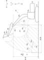
図1~図3を参照して、図1に示す輸送車位置判定装置30、ならびに、輸送車位置判定装置30が用いられる輸送車10および作業機械20について説明する。
1 to 3, the transport vehicle
輸送車10は、荷台12を有する車両である。輸送車10は、作業機械20によって積み込まれた物(積込対象物)を輸送するための車両であり、ダンプカーでもよく、トラックでもよい。輸送車10は、本体部11と、荷台12と、を備える。本体部11は、走行可能であり、荷台12を支持する。本体部11は、運転室11aを備える。
A
荷台12は、積込対象物を収容する。荷台12に収容される積込対象物は、例えば、土砂でもよく、廃棄物でもよい。荷台12は、運転室11aよりも、輸送車10における後側に配置される。以下では、運転室11aから荷台12に向かう側を「輸送車後側」、荷台12から運転室11aに向かう側を「輸送車前側」という。荷台12は、本体部11に対して可動でもよく、本体部11に固定されてもよい。荷台12は、平面部13を備える。
The
平面部13は、荷台12のうち、平面状または略平面状の部分である。平面部13は、床面13aと、後部あおり板面13bと、側部あおり板面13cと、鳥居面13dと、を備える。各平面部13(床面13aなど)は、全体として平面状または略平面状であればよい。各平面部13は、凹凸を有してもよく、緩やかな曲面を有してもよい。床面13aは、荷台12の底面である。後部あおり板面13bは、荷台12の輸送車後側の面であり、床面13aの輸送車後側の部分から上に突出する。側部あおり板面13cは、荷台12の左右の面であり(図3参照)、床面13aの左右の端部から上に突出する。鳥居面13dは、荷台12の輸送車前側の面であり、床面13aの輸送車前側の部分から上に突出する。鳥居面13dは、側部あおり板面13cよりも上に突出し、後部あおり板面13bよりも上に突出する。
The
作業機械20は、荷台12に積込対象物を積み込む作業(積込作業)を行う機械である。作業機械20は、例えば、積込対象物をすくうことが可能でもよく、積込対象物を挟んで掴むことが可能でもよい。作業機械20は、例えば建設作業を行う建設機械であり、例えばショベルなどである。以下では、作業機械20がショベルである場合について説明する。作業機械20は、下部走行体21と、上部旋回体23と、アタッチメント25と、を備える。
The
下部走行体21は、作業機械20を走行させる。下部走行体21は、例えばクローラを備える。上部旋回体23は、下部走行体21に旋回可能に搭載される。上部旋回体23は、キャブ23aを備える。キャブ23aは、作業機械20のオペレータが操作を行うための部分である。なお、作業機械20は、キャブ23a内のオペレータに操作されなくてもよく、作業機械20の外部のオペレータに操作(遠隔操作)されてもよく、コンピュータにより自動操作されてもよい。
The lower traveling
(作業機械20に関する方向)
下部走行体21に対する上部旋回体23の旋回の回転軸が延びる方向を、上下方向Zとする。上下方向Zにおいて、下部走行体21から上部旋回体23に向かう側(向き)を上側Z1とし、その逆側を下側Z2とする。上下方向Zに直交する方向であって、上部旋回体23に対してアタッチメント25が突出する側を前後方向Xの前側X1とし、その逆側を前後方向Xの後側X2とする。上下方向Zおよび前後方向Xのそれぞれに直交する方向を横方向Yとする。
(Direction with respect to work machine 20)
A vertical direction Z is defined as the direction in which the rotating shaft of the upper rotating
アタッチメント25は、積込対象物の運搬(移動)および解放(例えば放土など)を行う部分である。アタッチメント25は、ブーム25aと、アーム25bと、先端アタッチメント25cと、を備える。ブーム25aは、上部旋回体23に起伏可能(上下に回転可能)に取り付けられる。アーム25bは、ブーム25aに回転可能(押し引き可能)に取り付けられる。先端アタッチメント25cは、アタッチメント25の先端部に設けられ、アーム25bに回転可能に取り付けられる。先端アタッチメント25cは、積込対象物(例えば土砂)をすくうバケットでもよく、積込対象物を挟んで掴む装置(グラップルなど)でもよい。
The
輸送車位置判定装置30は、作業機械20に対する輸送車10の位置に関する判定を行う。輸送車位置判定装置30は、作業機械20から輸送車10への積込対象物の積込が可能な位置(積込作業可能な位置)に、輸送車10が配置されているか否かなどを判定する。輸送車位置判定装置30は、距離画像取得部40と、演算部50と、報知部61と、第2報知部62と、を備える。
The transport vehicle
距離画像取得部40は、荷台12の距離画像(荷台12を含む距離画像)を取得する。距離画像は、距離の情報(奥行の情報)を含む画像であり、三次元の情報である。距離画像取得部40は、距離画像取得部40から荷台12の各部(詳細は後述)までの距離を計測する。具体的には例えば、距離画像取得部40は、LiDAR(Light Detection and RangingまたはLaser Imaging Detection and Ranging)を備えてもよく、ステレオカメラを備えてもよく、TOF(Time Of Flight)センサを備えてもよい。
The distance
この距離画像取得部40は、作業機械20に設けられる。距離画像取得部40は、荷台12および荷台12の周辺部の距離画像を取得可能となる位置に配置される。距離画像取得部40は、例えば、キャブ23aの内部に配置(設置)されてもよく、キャブ23aの外部に配置されてもよく、図1に示す例ではキャブ23aの上面に配置される。なお、距離画像取得部40は、作業機械20とは異なる位置(作業機械20から離れた位置)に配置されてもよい(演算部50、報知部61、および第2報知部62についても同様)。
This distance
演算部50は、信号の入出力、判定や算出などの演算、情報の記憶などを行う。演算部50は、距離画像取得部40に取得された荷台12の距離画像を処理し、荷台12の三次元情報を算出する。
The
報知部61は、人に対して報知を行う。報知部61は、音、光、および振動の少なくともいずれかの報知を出力する(詳細は後述)。第2報知部62は、報知部61と同様に、人に対して報知を行う。第2報知部62と報知部61とは、兼用でも別体でもよい
The
(作動)
作業機械20は、以下のように作動するように構成される。
(activation)
(荷台12情報の算出)
演算部50は、距離画像取得部40に取得された距離画像に基づいて、荷台12の三次元情報(以下「荷台12情報」ともいう)を算出する。荷台12情報は、作業機械20に対する荷台12の位置(三次元位置)の情報を含む。荷台12情報は、荷台12の形状(三次元形状)の情報を含んでもよい。荷台12情報は、荷台12の全体の情報を含んでもよく、荷台12の一部のみの情報を含んでもよい。例えば、荷台12情報は、荷台12のうち、後述する荷台範囲Aの算出に必要な部分のみの情報を含んでもよい。
(Calculation of
The
演算部50は、荷台12を含む二次元の情報(二次元画像)と、荷台12の距離画像と、に基づいて荷台12情報を算出してもよい。具体的には例えば、荷台12情報は、次のように算出されてもよい。距離画像取得部40は、荷台12を含む距離画像だけでなく、荷台12を含む二次元画像も取得する。この場合、距離画像取得部40は、二次元画像を取得するセンサ(カメラなど)を備える。次に、演算部50は、画像から特定の形状を抽出するプログラムを利用することで、二次元画像における荷台12の位置を抽出(算出、推定)する。次に、演算部50は、二次元画像における荷台12の位置に基づいて、荷台12および荷台12の周囲の景色を含む距離画像から、荷台12の部分の距離画像を抽出する。ここで、演算部50は、後述する荷台範囲Aの算出に必要な部分についてのみ、二次元画像におけるの位置の抽出、および距離画像の抽出を行ってもよい。そして、演算部50は、抽出した荷台12の距離画像に基づいて、荷台12情報を算出する。なお、演算部50は、二次元画像を利用せずに三次元の荷台12情報を算出することが可能であれば、二次元画像を利用せずに荷台12情報を算出してもよい。
The
(荷台範囲A、解放範囲B、および適切解放範囲Cの概要)
演算部50は、荷台12の位置に関する範囲である荷台範囲Aを設定(算出)する。演算部50は、アタッチメント25から積込対象物を解放可能な領域(解放領域β(図2参照))に関する範囲である解放範囲Bを取得する。好ましくは、演算部50は、アタッチメント25による作業の効率に基づいて決定される適切解放範囲C(図3参照)を取得する。そして、演算部50は、「輸送車位置判定」を行う。具体的には、演算部50は、輸送車位置判定において、荷台範囲Aの少なくとも一部が解放範囲Bに含まれたか否かを判定する。演算部50は、輸送車位置判定において、荷台範囲Aの少なくとも一部が適切解放範囲C(図3参照)に含まれたか否かを判定してもよい。
(Outline of carrier range A, release range B, and appropriate release range C)
The
演算部50は、輸送車位置判定を、前後方向Xの情報に基づいて行ってもよく、前後方向Xおよび上下方向Zの情報に基づいて行ってもよい。演算部50は、輸送車位置判定を、図3に示すように、前後方向Xおよび横方向Yの情報(上下方向Zから見た範囲の情報、平面視における範囲の情報)に基づいて行ってもよい。演算部50は、輸送車位置判定を、前後方向X、横方向Y、および上下方向Zの情報(三次元情報)に基づいて行ってもよい。
The
(荷台範囲Aの設定)
演算部50は、距離画像取得部40に取得された距離画像に基づいて、荷台範囲Aを設定する。荷台範囲Aは、荷台12の位置に関する範囲である。ここで、荷台12の真上の領域を荷台領域αとする(図1、および図3を参照)。荷台領域αは、仮に荷台12を真上に移動させたとしたときの、荷台12の軌跡の領域(三次元の領域)である。なお、演算部50は、荷台領域αを算出してもよく、算出しなくてもよい。荷台範囲Aの詳細は、以下の通りである。
(Setting of loading platform range A)
The
(前後方向Xに関する荷台範囲Axの設定)
前後方向Xの情報に基づいて輸送車位置判定が行われる場合、演算部50は、前後方向Xに関する荷台範囲A(荷台範囲Ax)を、例えば次のように設定する。
(Setting of loading platform range Ax in longitudinal direction X)
When the transport vehicle position is determined based on the information in the longitudinal direction X, the
荷台範囲Axは、荷台領域αの前側X1の端(または略端)から、荷台領域αの後側X2の端(または略端)までの範囲である。さらに詳しくは、荷台範囲Axの前側X1の端(境界)の位置は、上部旋回体23が荷台12を向いたときに、平面部13(荷台12の面)のうち作業機械20から最も遠い面(具体的には鳥居面13d)の位置である。上記「上部旋回体23が荷台12を向いたとき」は、上部旋回体23の前側X1の正面に荷台12が配置されているときを意味する(以下同様)。なお、荷台範囲Axの前側X1の端の位置は、鳥居面13dの位置に基づく位置であって、鳥居面13dの位置とは異なる位置(例えば鳥居面13dの近傍、荷台12内部側の位置など)でもよい(以下の荷台範囲Aと荷台12との関係についても同様)。荷台範囲Axの後側X2の端の位置は、上部旋回体23が荷台12を向いたときに、平面部13のうち作業機械20に最も近い面(具体的には後部あおり板面13b)の位置である。
The bed range Ax is a range from the end (or approximately the end) of the front side X1 of the bed area α to the end (or approximately the end) of the rear side X2 of the bed area α. More specifically, the position of the end (boundary) of the front side X1 of the loading platform range Ax is the plane farthest from the
なお、前後方向Xに対して鳥居面13dが直交しない場合(傾いている場合)は、荷台範囲Axの前側X1の端は、鳥居面13dのうち最も後側X2の位置でもよい。前後方向Xに対して後部あおり板面13bが直交しない場合は、荷台範囲Axの後側X2の端は、後部あおり板面13bのうち最も前側X1の位置でもよい。
If the
(上下方向Zに関する荷台範囲Azの設定)
上下方向Zの情報に基づいて輸送車位置判定が行われる場合、演算部50は、上下方向Zに関する荷台範囲A(荷台範囲Az)を、例えば次のように設定する。荷台範囲Azは、荷台領域αの下側Z2の端よりも上側Z1の範囲である。さらに詳しくは、荷台範囲Azの下側Z2の端の位置は、荷台12に含まれる特定の部位の位置である。具体的には、荷台範囲Azの下側Z2の端の位置は、側部あおり板面13cおよび後部あおり板面13bの上側Z1端部の位置でもよく、床面13aの位置でもよく、鳥居面13dの上側Z1端部の位置でもよい。荷台範囲Azの上側Z1の端の位置は、設定されなくてもよく、例えば荷台12から所定の高さの位置などに設定されてもよい。
(Setting of loading platform range Az in vertical direction Z)
When transport vehicle position determination is performed based on information in the vertical direction Z, the
(前後方向Xおよび上下方向Zに関する荷台範囲Axzの設定)
前後方向Xおよび上下方向Zの情報に基づいて輸送車位置判定が行われる場合、演算部50は、前後方向Xおよび上下方向Zに関する荷台範囲A(荷台範囲Axz)を、例えば次のように設定する。荷台範囲Axzは、横方向Yから見た荷台領域αと同じ(または略同じ)範囲であり、荷台範囲Axかつ荷台範囲Azの範囲である。
(Setting of loading platform range Axz in longitudinal direction X and vertical direction Z)
When the transport vehicle position is determined based on the information in the longitudinal direction X and the vertical direction Z, the
(前後方向Xおよび横方向Yに関する荷台範囲Axyの設定)
図3に示すように、前後方向Xおよび横方向Yの情報に基づいて輸送車位置判定が行われる場合、演算部50(図1参照、以下の演算部50についても同様)は、前後方向Xおよび横方向Yに関する荷台範囲A(荷台範囲Axy)を、例えば次のように設定する。荷台範囲Axyは、上下方向Zから見た(平面視における)荷台領域αと同じ(または略同じ)範囲である。さらに詳しくは、荷台範囲Axyは、上下方向Zから見たとき、荷台12の積込対象物を収容可能な部分の内部の範囲であり、さらに具体的には、後部あおり板面13b、左右の側部あおり板面13c・13c、および鳥居面13dに囲まれた範囲である。荷台範囲Axyは、上下方向Zから見たとき、床面13aと重なる領域である。
(Setting of loading platform range Axy in longitudinal direction X and lateral direction Y)
As shown in FIG. 3, when transport vehicle position determination is performed based on information in the longitudinal direction X and the lateral direction Y, the calculation unit 50 (see FIG. 1; the same applies to the
(三次元の情報に関する荷台範囲Aの設定)
前後方向X、横方向Y、および上下方向Zの情報(三次元情報)に基づいて輸送車位置判定が行われてもよい。この場合、三次元情報である荷台範囲Aは、荷台領域αと同じ範囲である。
(Setting of carrier range A regarding three-dimensional information)
Transport vehicle position determination may be performed based on information in the longitudinal direction X, lateral direction Y, and vertical direction Z (three-dimensional information). In this case, the loading platform range A, which is three-dimensional information, is the same range as the loading platform area α.
(解放範囲Bの取得)
演算部50は、図2に示す解放範囲Bを取得する。解放範囲Bは、先端アタッチメント25cから積込対象物を解放可能な領域(下記の解放領域β)に関する範囲である。演算部50は、予め解放範囲Bを記憶してもよく、解放範囲Bを算出してもよい。
(Acquisition of release range B)
The
下部走行体21が走行することなくアタッチメント25が作動したときに先端アタッチメント25cから積込対象物を解放可能な領域を、解放領域βとする。解放領域βは、略輪状の立体形状である(図2および図3を参照)。上記「アタッチメント25が作動」は、例えば、下記の[例1a]~[例1d]の少なくともいずれかの作動である。[例1a]上部旋回体23に対するブーム25aの回転。[例1b]ブーム25aに対するアーム25bの回転。[例1c]、アーム25bに対する先端アタッチメント25cの回転。[例1d]下部走行体21に対して上部旋回体23が旋回することによる、下部走行体21に対するアタッチメント25の回転(旋回)。
A release area β is defined as an area in which the loading object can be released from the
解放領域βは、アタッチメント25の情報に基づいて決まる。具体的には、解放領域βは、アタッチメント25の各構成要素(ブーム25aなど)の寸法、および、アタッチメント25の各構成要素がとりうる角度範囲(例えば上部旋回体23に対するブーム25aの起伏角度の範囲)の情報に基づいて決まる。なお、演算部50は、解放領域βを算出してもよく、算出しなくてもよい。
The release area β is determined based on the information of the
先端アタッチメント25cが配置され得る位置であっても、先端アタッチメント25cから積込対象物を解放することが想定されない位置は、解放領域βに含まれなくてもよい。具体的には例えば、下部走行体21の下側Z2の端よりも下側Z2の位置は、解放領域βに含まれなくてもよく、含まれてもよい。また、下部走行体21の前側X1端部よりも後側X2の領域は、荷台12(図1参照)を配置不可能(または困難)であるため、解放領域βに含まれなくてもよい。
Even if the
図2に示すように、先端アタッチメント25cがバケットの場合、先端アタッチメント25cがアーム25bに対して回転することで、積込対象物が先端アタッチメント25cから解放される。そのため、先端アタッチメント25cが積込対象物を解放する際の先端アタッチメント25cの軌跡の領域は、解放領域βに含まれなくてもよい。先端アタッチメント25cが積込対象物を挟んで掴む装置である場合は、積込対象物が解放される際に、アーム25bに対して先端アタッチメント25cが回転する必要はない。この場合は、解放領域βは、先端アタッチメント25cの先端部の可動領域β0の範囲内(または略範囲内)でもよい。
As shown in FIG. 2, when the
(前後方向Xに関する解放範囲Bxの取得)
前後方向Xの情報に基づいて輸送車位置判定が行われる場合、演算部50は、前後方向Xに関する解放範囲B(解放範囲Bx)を取得する。例えば、解放範囲Bxの前側X1の端(境界)の位置は、解放領域βの前側X1の端の位置である。すなわち、解放範囲Bxの前側X1の端の位置は、下部走行体21が走行することなくアタッチメント25が作動したときに先端アタッチメント25cから積込対象物を解放可能な領域のうち、最も前側X1の位置である。なお、解放範囲Bxの前側X1の端の位置は、解放領域βの前側X1の端の位置に基づく位置であって、解放領域βの前側X1の端の位置とは異なる位置でもよい(以下の解放範囲Bと解放領域βとの関係についても同様)。解放範囲Bxの後側X2の端の位置は、解放領域βの後側X2の端の位置である。
(Acquisition of Release Range Bx in Front-Back Direction X)
When transport vehicle position determination is performed based on the information in the longitudinal direction X, the
(上下方向Zに関する解放範囲Bzの取得)
上下方向Zの情報に基づいて輸送車位置判定が行われる場合、演算部50は、上下方向Zに関する解放範囲Bzを取得する。例えば、解放範囲Bzの上側Z1の端の位置は、解放領域βの上側Z1の端の位置である。解放範囲Bzの下側Z2の端の位置は、解放領域βの下側Z2の端の位置である。
(Acquisition of release range Bz in vertical direction Z)
When transport vehicle position determination is performed based on the information in the vertical direction Z, the
(前後方向Xおよび上下方向Zに関する解放範囲Bxzの取得)
前後方向Xおよび上下方向Zの情報に基づいて輸送車位置判定が行われる場合、演算部50は、前後方向Xおよび上下方向Zに関する解放範囲Bxzを取得する。解放範囲Bxzは、横方向Yから見た解放領域βの範囲である。
(Acquisition of release range Bxz in front-back direction X and up-down direction Z)
When transport vehicle position determination is performed based on the information in the longitudinal direction X and the vertical direction Z, the
(前後方向Xおよび横方向Yに関する解放範囲Bxyの取得)
図3に示すように、前後方向Xおよび横方向Yの情報に基づいて輸送車位置判定が行われる場合、演算部50は、前後方向Xおよび横方向Yに関する解放範囲Bxyを取得する。解放範囲Bxyは、上下方向Zから見た解放領域βの範囲(リング状の範囲)である。
(Acquisition of Release Range Bxy in Front-Back Direction X and Lateral Direction Y)
As shown in FIG. 3 , when transport vehicle position determination is performed based on information in the longitudinal direction X and lateral direction Y, the
(三次元の情報に関する解放範囲Bの取得)
前後方向X、横方向Y、および上下方向Zの情報(三次元情報)に基づいて輸送車位置判定が行われる場合、演算部50は、三次元情報である解放範囲Bを取得する。三次元情報の解放範囲Bは、解放領域βと同じ範囲である。
(Acquisition of release range B regarding three-dimensional information)
When transport vehicle position determination is performed based on information (three-dimensional information) in the longitudinal direction X, lateral direction Y, and vertical direction Z, the
(適切解放範囲Cの取得)
演算部50は、適切解放範囲Cを取得する。適切解放範囲Cは、解放範囲Bに含まれ、解放範囲Bよりも狭い範囲である。適切解放範囲Cは、アタッチメント25による作業の効率(作業効率)に基づいて決定される。演算部50は、予め適切解放範囲Cを記憶してもよく、適切解放範囲Cを算出してもよい。具体的には例えば、適切解放範囲Cは、次のように設定される。
(Acquisition of appropriate release range C)
The
適切解放範囲Cの前側X1の端(境界)は、解放範囲Bの前側X1の端よりも後側X2に設定されてもよい。その理由の例は次の通りである。[例2a]上部旋回体23の旋回中心から先端アタッチメント25cの前側X1の端までの距離(作業半径)が小さいほど、作業機械20が安定しやすく、作業効率が良い。[例2b]作業半径が小さいほど、下部走行体21に対する上部旋回体23の旋回加速度を大きくでき、作業時間を短縮でき、作業効率が良い。[例2c]作業半径が小さいほど、上部旋回体23の旋回に必要なエネルギーを低減でき、作業効率が良い。[例2d]作業半径が最大値または略最大値のときに比べ、作業半径が小さいときは、アタッチメント25の姿勢の自由度が高いので、作業効率が良い。
The front X1 end (boundary) of the appropriate release range C may be set to the rear X2 of the release range B front X1 end. Examples of the reasons are as follows. [Example 2a] The smaller the distance (working radius) from the turning center of the
[例2e]図3に示す適切解放範囲Cは、先端アタッチメント25cによる積込対象物の運搬を効率良く行えるか否かに基づいて設定されてもよい。具体例は次の通りである。図2に示すように、バケットである先端アタッチメント25cの基端部と先端部とを通る面を、面25cfとする。作業半径が大きい(最大値または略最大値)ときは、アーム25bの長手方向が水平方向または略水平方向となる。このとき、アーム25bに対して先端アタッチメント25cを回転させるシリンダ(図示なし)を伸縮させても、先端アタッチメント25cの面25cfの延びる方向が水平方向(または略水平方向)になることができない。そのため、先端アタッチメント25cが運搬可能な積込対象物の量が制限される。一方、作業半径が最大値または略最大値のときに比べ、作業半径が小さいときは、先端アタッチメント25cの面25cfの延びる方向が水平方向になり得る。よって、先端アタッチメント25cが運搬可能な積込対象物の量が制限されず、作業効率が良い。
[Example 2e] The appropriate release range C shown in FIG. 3 may be set based on whether or not the object to be loaded can be efficiently transported by the
図3に示すように、適切解放範囲Cの後側X2の端(境界)は、解放範囲Bの後側X2の端よりも前側X1に設定されてもよい。その理由の例は次の通りである。[例3a]作業半径が最小値または略最小値よりも大きいときは、先端アタッチメント25cがキャブ23aに接触したり、先端アタッチメント25cがキャブ23aに接触することを防ぐ機能が作動したりする問題が生じない。よって、作業効率が良い。なお、図2に示す例では、先端アタッチメント25cはキャブ23aに接触し得ないが、アタッチメント25の寸法や形状によっては先端アタッチメント25cがキャブ23aに接触する場合がある。[例3b]作業半径が最小値または略最小値のときに比べ、作業半径が大きいときは、アタッチメント25の姿勢の自由度が高いので、作業効率が良い。
As shown in FIG. 3 , the rear X2 end (boundary) of the appropriate release range C may be set further forward X1 than the rear X2 end of the release range B. As shown in FIG. Examples of the reasons are as follows. [Example 3a] When the working radius is larger than the minimum value or approximately the minimum value, there is a problem that the
なお、前後方向Xの情報に基づいて輸送車位置判定が行われる場合、演算部50は、前後方向Xに関する適切解放範囲C(図3参照)を取得してもよい(他の方向についても同様)。適切解放範囲Cは、複数段階(適切な範囲、より適切な範囲、さらに適切な範囲、など)設けられてもよい。
In addition, when transport vehicle position determination is performed based on information in the longitudinal direction X, the
(判定)
演算部50は、図3に示す荷台範囲Aの少なくとも一部が解放範囲Bに含まれたか否かを判定する。例えば、前後方向Xの情報に基づいて輸送車位置判定が行われる場合は、演算部50は、前後方向Xに関する荷台範囲Axの少なくとも一部が、前後方向Xに関する解放範囲Bxに含まれたか否かを判定する(他の方向についても同様)。また、演算部50は、荷台範囲Aの少なくとも一部が適切解放範囲Cに含まれた否かを判定する。演算部50は、荷台範囲Aの全体が解放範囲Bに含まれた否かを判定してもよい。演算部50は、荷台範囲Aの全体が適切解放範囲Cに含まれたか否かを判定してもよい。
(judgement)
The
(判定結果に応じた出力)
演算部50は、判定結果に応じて、信号を出力する。演算部50が出力する信号は、様々に用いることができる。例えば、演算部50が出力する信号は、何らかの制御に用いられてもよく、下記の報知に用いられてもよく、数値などの情報を含んでもよい。
(Output according to judgment result)
The
(報知)
演算部50は、図1に示す荷台範囲Aの少なくとも一部が解放範囲Bに含まれた場合、報知部61に報知を行わせる(報知を行わせるための信号を出力する)。演算部50は、荷台範囲Aが解放範囲Bに含まれない場合、報知部61に報知を行わせない。報知部61は、積込作業が可能な位置に輸送車10が配置されていることを報知する。報知部61は、例えば輸送車10の運転手に対して報知(合図)を出力する。報知部61による報知は、上記のように、音、光、および振動の少なくともいずれかである。具体的には、報知部61は、輸送車10および作業機械20の少なくともいずれかの音声出力部(ホーン、スピーカなど)でもよい。報知部61は、輸送車10および作業機械20の少なくともいずれかの光出力部(画面、ライトなど)でもよく、輸送車10の運転手に接触する振動発生装置でもよい。
(notification)
When at least part of the loading range A shown in FIG. 1 is included in the release range B, the
演算部50は、荷台範囲Aの少なくとも一部が適切解放範囲C(図3参照)に含まれた場合、第2報知部62に報知を行わせる。演算部50は、荷台範囲Aが適切解放範囲C(図3参照)に含まれない場合、第2報知部62に報知を行わせない。第2報知部62は、積込作業を適切に行える位置に輸送車10が配置されていることを報知する。第2報知部62は、例えば輸送車10の運転手に対して報知(合図)を出力する。第2報知部62による報知の具体例は、報知部61による報知の具体例と同様である。第2報知部62による報知と、報知部61による報知とは異なる。例えば、報知部61の報知と第2報知部62の報知とで、音色、音声の内容、光の色、強さ、点滅のパターン、振動のパターンなどが異なる。
The
演算部50は、荷台範囲Aの全体が解放範囲Bに含まれた場合に、報知を行わせてもよい。演算部50は、荷台範囲Aの全体が適切解放範囲Cに含まれた場合に、報知を行わせてもよい。
The
(情報出力)
演算部50は、荷台範囲Aが解放範囲Bに含まれていないときに、荷台範囲Aが解放範囲Bに含まれるまでに輸送車10を移動させる必要のある距離の情報(残り距離)を出力してもよい。同様に、演算部50は、荷台範囲Aが適切解放範囲Cに含まれていないときに、荷台範囲Aが適切解放範囲Cに含まれるまでに輸送車10を移動させる必要のある距離(残り距離)の情報を出力してもよい。残り距離の情報は、例えば輸送車10の運転手に音声や表示などにより通知されてもよい(下記の移動方向の情報も同様)。
(information output)
When the loading range A is not included in the release range B, the
演算部50は、荷台範囲Aが解放範囲Bに含まれていないときに、荷台範囲Aが解放範囲Bに含まれるための輸送車10の移動方向の情報を出力してもよい(適切解放範囲Cについても同様)。さらに詳しくは、演算部50は、距離画像取得部40に取得された距離画像に基づいて、図3に示す角度θを算出および出力する。角度θは、上部旋回体23(作業機械20)に対する荷台12の平面部13の角度(傾き)である。具体的には例えば、角度θは、前後方向Xと、平面部13と、がなす角度である。さらに詳しくは、角度θは、前後方向Xと、荷台12の平面部13のうち上部旋回体23に最も近い面(図3では後部あおり板面13b)と、がなす角度である。なお、演算部50は、荷台範囲Aが解放範囲Bに含まれているときに、角度θの情報を算出および出力してもよい(適切解放範囲Cも同様)。
When the loading range A is not included in the release range B, the
(その他の出力)
演算部50は、荷台範囲Aの少なくとも一部が解放範囲Bに含まれた場合に、その旨(荷台範囲Aが解放範囲Bに含まれたこと)を示す信号を出力してもよい(適切解放範囲Cも同様)。演算部50は、報知部61や第2報知部62による報知以外を目的とした信号を出力してもよい。
(other output)
When at least part of the platform range A is included in the release range B, the
(作業機械20の遠隔または自動操作について)
図1に示す作業機械20のキャブ23a内にオペレータがいる場合、輸送車10の位置が積込作業可能な位置であるか否かを、オペレータが判断できる。そのため、積込作業可能な位置に輸送車10が到達したときに、オペレータが、輸送車10の運転手に報知(具体的には停止の合図)を行える。一方、作業機械20が自動操縦される場合、上記のオペレータによる判断はできない。そのため、輸送車10の位置が積込作業可能な位置であるか否かを自動的に判定できることが望まれる。また、作業機械20が遠隔操作される場合、オペレータは画面を見て作業機械20を操作する。そのため、オペレータは、作業機械20から輸送車10までの距離を把握しにくく、輸送車10の位置が積込作業可能な位置であるか否かを判断するのが難しい。一方、本実施形態の輸送車位置判定装置30では、輸送車10の位置が積込作業可能な位置であるか否かを自動的に判定することができる。なお、本実施形態において、作業機械20が自動操作されなくてもよく、遠隔操作されなくてもよく、キャブ23a内にオペレータがいてもよい。
(Remote or automatic operation of work machine 20)
When the operator is inside the
(効果)
図1に示す輸送車位置判定装置30による効果は、次の通りである。
(effect)
The effects of the transportation vehicle
(第1の発明の効果)
輸送車位置判定装置30は、アタッチメント25を有する作業機械20に用いられる。アタッチメント25は、輸送車10の荷台12に積み込まれる積込対象物の運搬および解放を行う。輸送車位置判定装置30は、距離画像取得部40と、演算部50と、を備える。
(Effect of the first invention)
A transport vehicle
[構成1-1]距離画像取得部40は、荷台12の距離画像を取得する。演算部50は、距離画像取得部40に取得された荷台12の距離画像に基づいて、荷台12の位置に関する範囲である荷台範囲Aを設定する。
[Arrangement 1-1] The distance
[構成1-2]演算部50は、作業機械20が走行することなくアタッチメント25が作動したときにアタッチメント25から積込対象物を解放可能な領域(解放領域β(図2参照))に関する範囲である解放範囲Bを取得する。演算部50は、荷台範囲Aが解放範囲Bに含まれたか否かを判定する。
[Arrangement 1-2] The
上記[構成1-2]により、輸送車10の荷台範囲A(の少なくとも一部)が、作業機械20の解放範囲Bに含まれたか否かが、演算部50に自動的に判定される。よって、荷台範囲Aが解放範囲Bに含まれるような位置に輸送車10が配置されたか否かを、演算部50が自動的に判定することができる。ここで、荷台範囲Aは、上記[構成1-1]のように、荷台12の距離画像に基づいて設定される。よって、荷台12が変更された場合でも、変更後の荷台12の距離画像に基づいて、荷台範囲Aが設定される。よって、輸送車10の種類が変更された場合でも、荷台範囲Aが解放範囲Bに含まれたか否かを自動的に判定することができる。したがって、輸送車10の種類が変更された場合でも、作業機械20に対する輸送車10の位置を判定することができる。
With the above [Configuration 1-2], the
(第2の発明の効果)
作業機械20は、下部走行体21と、下部走行体21に対して旋回可能な上部旋回体23と、を備える。
(Effect of the second invention)
The
[構成2]荷台範囲Axは、上部旋回体23が荷台12を向いたときに、荷台12の面のうち上部旋回体23に最も近い面と、上部旋回体23から最も遠い面との上部旋回体23の前後方向Xにおける間の領域の少なくとも一部に設定される。
[Configuration 2] The loading platform range Ax is defined by the surface of the
上記[構成1]における荷台範囲Aは、「荷台12の位置に関する範囲」であるところ、上記[構成2]では、荷台範囲Axは、荷台12の前後方向Xの両端の2面(例えば後部あおり板面13bおよび鳥居面13d)の間の領域の少なくとも一部に設定される。よって、荷台範囲Axを、荷台12の位置に基づいた適切な範囲に設定することができる。その結果、荷台範囲Aが解放範囲Bに含まれたと判定された場合に(上記[構成1-1]参照)、アタッチメント25から荷台12に積込対象物を積み込める可能性を高くすることができる。
In the above [configuration 1], the loading platform range A is "a range related to the position of the
(第3の発明の効果)
[構成3]荷台範囲Azは、荷台12よりも上側Z1の領域の少なくとも一部に設定される。
(Effect of the third invention)
[Configuration 3] The loading platform range Az is set to at least a part of the area Z1 above the
上記[構成1]における荷台範囲Aは、「荷台12の位置に関する範囲」であるところ、上記[構成3]では、荷台範囲Azは、荷台12よりも上側Z1の領域の少なくとも一部に設定される。よって、荷台範囲Azを、荷台12の位置に基づいた適切な範囲に設定することができる。その結果、荷台範囲Aが解放範囲Bに含まれたと判定された場合に(上記[構成1-1]参照)、アタッチメント25から荷台12に積込対象物を積み込める可能性を高くすることができる。
While the loading platform range A in the above [Configuration 1] is "a range related to the position of the
(第4の発明の効果)
[構成4]図3に示すように、荷台範囲Axyは、平面視において(上側Z1から見たときに)荷台12と重なる領域の少なくとも一部に設定される。
(Effect of the fourth invention)
[Configuration 4] As shown in FIG. 3, the loading platform range Axy is set to at least a portion of the area overlapping the
上記[構成1]における荷台範囲Aは、「荷台12の位置に関する範囲」であるところ、上記[構成4]では、荷台範囲Axyは、平面視において荷台12と重なる領域の少なくとも一部に設定される。よって、荷台範囲Axyを、荷台12の位置に基づいた適切な範囲に設定することができる。その結果、荷台範囲Aが解放範囲Bに含まれたと判定された場合に(上記[構成1-1]参照)、アタッチメント25から荷台12に積込対象物を積み込める可能性を高くすることができる。
While the loading platform range A in the above [Configuration 1] is "a range related to the position of the
(第5の発明の効果)
[構成5]図1に示すように、輸送車位置判定装置30は、報知部61を備える。報知部61は、音、光、および振動の少なくともいずれかの報知を出力する。演算部50は、荷台範囲Aの少なくとも一部が解放範囲Bに含まれた場合、報知部61に報知を行わせる。
(Effect of the fifth invention)
[Arrangement 5] As shown in FIG.
上記[構成5]により、荷台範囲Aの少なくとも一部が解放範囲Bに含まれたことを、人(例えば輸送車10の運転手など)に知らせることができる。 With the above [Configuration 5], it is possible to notify a person (for example, the driver of the transportation vehicle 10) that at least a part of the loading range A is included in the release range B.
(第6の発明の効果)
[構成6]演算部50は、荷台範囲Aが解放範囲Bに含まれていないときに、荷台範囲Aの少なくとも一部が解放範囲Bに含まれるまでに輸送車10を移動させる必要のある距離(残り距離)の情報を出力する。
(Effect of the sixth invention)
[Configuration 6] When the loading range A is not included in the release range B, the
上記[構成6]により、演算部50が、残り距離の情報を出力することで、人(例えば輸送車10の運転手など)やコンピュータなどに残り距離の情報を伝達することができる。
According to the above [configuration 6], the
(第7の発明の効果)
[構成7]演算部50は、図3に示す適切解放範囲Cを取得する。適切解放範囲Cは、解放範囲Bに含まれ、解放範囲Bよりも狭い範囲であり、アタッチメント25による作業の効率に基づいて決定される。演算部50は、荷台範囲Aの少なくとも一部が適切解放範囲Cに含まれたか否かを判定する。
(Effect of the seventh invention)
[Configuration 7] The
上記[構成7]では、適切解放範囲Cが、アタッチメント25による作業(以下、単に「作業」)の効率に基づいて決定される。よって、適切解放範囲Cの外側で作業が行われるよりも、適切解放範囲Cの内側で作業が行われる方が、作業の効率が良くなるように、適切解放範囲Cが設定された場合、かつ、適切解放範囲Cの内側で作業が行われた場合、作業の効率を向上させることができる。
In the above [configuration 7], the appropriate release range C is determined based on the efficiency of the work (hereinafter simply "work") performed by the
(第8の発明の効果)
[構成8]図1に示すように、輸送車位置判定装置30は、第2報知部62を備える。第2報知部62は、音、光、および振動の少なくともいずれかの報知を出力する。演算部50は、図3に示す荷台範囲Aの少なくとも一部が適切解放範囲Cに含まれた場合、第2報知部62(図1参照)に報知を行わせる。
(Effect of the eighth invention)
[Arrangement 8] As shown in FIG. The
上記[構成8]により、荷台範囲Aの少なくとも一部が適切解放範囲Cに含まれたことを、人(例えば輸送車10の運転手など)に知らせることができる。 With the above [Configuration 8], it is possible to notify a person (for example, the driver of the transportation vehicle 10) that at least a part of the loading range A is included in the appropriate release range C.
(第9の発明の効果)
[構成9]演算部50は、荷台範囲Aが適切解放範囲Cに含まれていないときに、荷台範囲Aが適切解放範囲Cに含まれるまでに輸送車10を移動させる必要のある距離(残り距離)の情報を出力する。
(Effect of the ninth invention)
[Configuration 9] When the loading range A is not included in the appropriate release range C, the
上記[構成9]により、演算部50が、残り拒理の情報を出力することで、人(例えば輸送車10の運転手など)やコンピュータなどに残り距離の情報を伝達することができる。
According to the above [configuration 9], the
(第10の発明の効果)
演算部50は、距離画像取得部40(図1参照)に取得された距離画像に基づいて、作業機械20に対する、荷台12の平面部13(面)の角度θを、算出および出力する。
(Effect of the tenth invention)
Based on the distance image acquired by the distance image acquisition unit 40 (see FIG. 1), the
上記[構成10]により、演算部50が角度θを出力することで、人(例えば輸送車10の運転手)やコンピュータなどに角度θを伝達することができる。
According to [Configuration 10] described above, the angle θ can be transmitted to a person (for example, the driver of the transportation vehicle 10), a computer, or the like by outputting the angle θ from the
(変形例)
上記実施形態は様々に変形されてもよい。例えば、上記実施形態の各構成要素の配置や形状が変更されてもよい。例えば、構成要素の数が変更されてもよく、構成要素の一部が設けられなくてもよい。例えば、互いに異なる複数の部材や部分として説明したものが、一つの部材や部分とされてもよい。例えば、一つの部材や部分として説明したものが、互いに異なる複数の部材や部分に分けて設けられてもよい。例えば、荷台領域αや荷台範囲Aは、荷台12に対して一定の領域や範囲でもよく、手動操作により変えられてもよく、何らかの条件に応じて自動的に変えられてもよい(解放領域β、解放範囲B、および適切解放範囲Cも同様)。
(Modification)
The above embodiments may be modified in various ways. For example, the arrangement and shape of each component of the above embodiment may be changed. For example, the number of components may vary and some components may not be provided. For example, what has been described as a plurality of different members or parts may be treated as a single member or part. For example, what has been described as one member or portion may be divided into a plurality of different members or portions. For example, the bed area α and the bed range A may be fixed areas or ranges with respect to the
10 輸送車
12 荷台
13 平面部(面)
20 作業機械
21 下部走行体
23 上部旋回体
25 アタッチメント
30 輸送車位置判定装置
40 距離画像取得部
50 演算部
61 報知部
62 第2報知部
A、Ax、Az、Axz、Axy 荷台範囲
B、Bx、Bz、Bxz、Bxy 解放範囲
C 適切解放範囲
X 前後方向
X1 前側
X2 後側
β 解放領域(積込対象物を解放可能な領域)
10
20 working
X1 front side
X2 rear side
β release area (area where objects can be released)
Claims (12)
前記荷台の三次元情報である距離画像を取得する距離画像取得部と、
演算部と、
を備え、
前記距離画像取得部は、前記距離画像取得部から前記荷台までの距離を計測することで、前記荷台の前記距離画像を取得し、
前記演算部は、
前記距離画像取得部に取得された前記荷台の前記距離画像に基づいて荷台範囲を設定し、
前記作業機械が走行することなく前記アタッチメントが作動したときに前記アタッチメントから前記積込対象物を解放可能な領域に基づいて決定される範囲である解放範囲を取得し、
前記荷台範囲が前記解放範囲に含まれたか否かを判定する、
輸送車位置判定装置。 A transport vehicle position determination device used in a work machine having an attachment for transporting and releasing an object to be loaded on the platform of the transport vehicle,
a distance image acquisition unit that acquires a distance image that is three-dimensional information of the loading platform;
a computing unit;
with
The distance image acquiring unit acquires the distance image of the loading platform by measuring a distance from the distance image acquiring unit to the loading platform,
The calculation unit is
setting a bed range based on the distance image of the bed acquired by the distance image acquisition unit;
acquiring a release range, which is a range determined based on a range in which the object can be released from the attachment when the attachment is operated without the work machine traveling;
determining whether the loading range is included in the release range;
Vehicle position determination device.
前記作業機械は、
下部走行体と、
前記下部走行体に対して旋回可能な上部旋回体と、
を備え、
前記荷台範囲は、前記上部旋回体が前記荷台を向いたときに、前記荷台の面のうち前記上部旋回体から最も遠い面と前記上部旋回体に最も近い面との前記上部旋回体の前後方向における間の領域の少なくとも一部に設定される、
輸送車位置判定装置。 The transport vehicle position determination device of claim 1,
The working machine is
a lower running body;
an upper rotating body capable of rotating with respect to the lower traveling body;
with
The range of the loading platform is defined by the front-rear direction of the upper rotating body between the surface of the loading platform that is farthest from the upper rotating body and the surface that is closest to the upper rotating body when the upper rotating body faces the loading platform. set to at least part of the area between
Vehicle position determination device.
前記荷台範囲は、前記荷台よりも上側の領域の少なくとも一部に設定される、
輸送車位置判定装置。 The transport vehicle position determination device according to claim 1 or 2,
The loading platform range is set to at least part of an area above the loading platform,
Vehicle position determination device.
前記荷台範囲は、平面視において前記荷台と重なる領域の少なくとも一部に設定される、
輸送車位置判定装置。 The transport vehicle position determination device according to any one of claims 1 to 3,
The loading platform range is set to at least part of an area that overlaps with the loading platform in plan view,
Vehicle position determination device.
音、光、および振動の少なくともいずれかの報知を出力する報知部を備え、
前記演算部は、前記荷台範囲の少なくとも一部が前記解放範囲に含まれた場合、前記報知部に報知を行わせる、
輸送車位置判定装置。 The transport vehicle position determination device according to any one of claims 1 to 4,
A notification unit that outputs at least one notification of sound, light, and vibration,
The calculation unit causes the notification unit to perform notification when at least part of the loading range is included in the release range.
Vehicle position determination device.
前記演算部は、前記荷台範囲が前記解放範囲に含まれていないときに、前記荷台範囲の少なくとも一部が前記解放範囲に含まれるまでに前記輸送車を移動させる必要のある距離の情報を出力する、
輸送車位置判定装置。 The transport vehicle position determination device according to any one of claims 1 to 5,
When the loading range is not included in the release range, the computing unit outputs information on the distance that the transportation vehicle needs to be moved until at least part of the loading range is included in the release range. do,
Vehicle position determination device.
前記演算部は、
前記解放範囲に含まれ、前記解放範囲よりも狭い範囲である適切解放範囲を取得し、
前記荷台範囲の少なくとも一部が前記適切解放範囲に含まれたか否かを判定する、
輸送車位置判定装置。 The transport vehicle position determination device according to any one of claims 1 to 6,
The calculation unit is
Acquiring an appropriate release range that is included in the release range and narrower than the release range;
Determining whether at least a portion of the cargo bed range is included in the appropriate release range;
Vehicle position determination device.
前記作業機械の上部旋回体に対して前記アタッチメントが突出する側を前側とし、前側とは逆側を後側としたとき、
前記適切解放範囲の前側の端は、前記解放範囲の前側の端よりも後側に設定される、
輸送車位置判定装置。 A transport vehicle position determination device according to claim 7,
When the side where the attachment protrudes from the upper revolving body of the working machine is defined as the front side, and the side opposite to the front side is defined as the rear side,
The front end of the appropriate release range is set on the rear side of the front end of the release range,
Vehicle position determination device.
前記作業機械の上部旋回体に対して前記アタッチメントが突出する側を前側とし、前側とは逆側を後側としたとき、
前記適切解放範囲の後側の端は、前記解放範囲の後側の端よりも前側に設定される、
輸送車位置判定装置。 A transport vehicle position determination device according to claim 7 or 8,
When the side where the attachment protrudes from the upper revolving body of the working machine is defined as the front side, and the side opposite to the front side is defined as the rear side,
The rear end of the appropriate release range is set forward of the rear end of the release range,
Vehicle position determination device.
音、光、および振動の少なくともいずれかの報知を出力する第2報知部を備え、
前記演算部は、前記荷台範囲の少なくとも一部が前記適切解放範囲に含まれた場合、前記第2報知部に報知を行わせる、
輸送車位置判定装置。 The transport vehicle position determination device according to any one of claims 7 to 9,
A second notification unit that outputs at least one notification of sound, light, and vibration,
The calculation unit causes the second notification unit to perform notification when at least part of the loading range is included in the appropriate release range.
Vehicle position determination device.
前記演算部は、前記荷台範囲が前記適切解放範囲に含まれていないときに、前記荷台範囲が前記適切解放範囲に含まれるまでに前記輸送車を移動させる必要のある距離の情報を出力する、
輸送車位置判定装置。 The transport vehicle position determination device according to any one of claims 7 to 10,
When the loading range is not included in the appropriate release range, the computing unit outputs information on the distance that the transportation vehicle needs to be moved until the loading range is included in the appropriate release range.
Vehicle position determination device.
前記演算部は、前記距離画像取得部に取得された前記距離画像に基づいて、前記作業機械に対する、前記荷台の面の角度を、算出および出力する、
輸送車位置判定装置。 The transport vehicle position determination device according to any one of claims 1 to 11,
The calculation unit calculates and outputs an angle of the surface of the loading platform with respect to the work machine, based on the distance image acquired by the distance image acquisition unit.
Vehicle position determination device.
Priority Applications (5)
| Application Number | Priority Date | Filing Date | Title |
|---|---|---|---|
| JP2019176036A JP7306191B2 (en) | 2019-09-26 | 2019-09-26 | Transportation vehicle position determination device |
| PCT/JP2020/026364 WO2021059658A1 (en) | 2019-09-26 | 2020-07-06 | Device for assessing position of conveyance vehicle |
| CN202080066937.2A CN114450453B (en) | 2019-09-26 | 2020-07-06 | Position determining device for transport vehicle |
| EP20869069.3A EP4023823B1 (en) | 2019-09-26 | 2020-07-06 | Device for assessing position of conveyance vehicle |
| US17/763,092 US20220388791A1 (en) | 2019-09-26 | 2020-07-06 | Device for assessing position of conveyance vehicle |
Applications Claiming Priority (1)
| Application Number | Priority Date | Filing Date | Title |
|---|---|---|---|
| JP2019176036A JP7306191B2 (en) | 2019-09-26 | 2019-09-26 | Transportation vehicle position determination device |
Publications (2)
| Publication Number | Publication Date |
|---|---|
| JP2021055256A JP2021055256A (en) | 2021-04-08 |
| JP7306191B2 true JP7306191B2 (en) | 2023-07-11 |
Family
ID=75166035
Family Applications (1)
| Application Number | Title | Priority Date | Filing Date |
|---|---|---|---|
| JP2019176036A Active JP7306191B2 (en) | 2019-09-26 | 2019-09-26 | Transportation vehicle position determination device |
Country Status (5)
| Country | Link |
|---|---|
| US (1) | US20220388791A1 (en) |
| EP (1) | EP4023823B1 (en) |
| JP (1) | JP7306191B2 (en) |
| CN (1) | CN114450453B (en) |
| WO (1) | WO2021059658A1 (en) |
Families Citing this family (3)
| Publication number | Priority date | Publication date | Assignee | Title |
|---|---|---|---|---|
| JP2023012254A (en) * | 2021-07-13 | 2023-01-25 | コベルコ建機株式会社 | Abnormal operation detection system |
| JP2023046879A (en) * | 2021-09-24 | 2023-04-05 | コベルコ建機株式会社 | Vehicle discrimination system |
| JP2024004776A (en) * | 2022-06-29 | 2024-01-17 | 日立建機株式会社 | Work machine |
Citations (2)
| Publication number | Priority date | Publication date | Assignee | Title |
|---|---|---|---|---|
| JP2000192514A (en) | 1998-12-28 | 2000-07-11 | Hitachi Constr Mach Co Ltd | Automatically operating construction machine and operating method thereof |
| JP2001091345A (en) | 1999-09-17 | 2001-04-06 | Hitachi Constr Mach Co Ltd | Monitoring apparatus of working amount of hydraulic shovel |
Family Cites Families (8)
| Publication number | Priority date | Publication date | Assignee | Title |
|---|---|---|---|---|
| JP2922727B2 (en) | 1992-07-01 | 1999-07-26 | 株式会社フジタ | Travel control system for earth and sand vehicles |
| JP3789218B2 (en) * | 1997-10-22 | 2006-06-21 | 日立建機株式会社 | Automatic operation construction machine and operation method thereof |
| US8768583B2 (en) * | 2012-03-29 | 2014-07-01 | Harnischfeger Technologies, Inc. | Collision detection and mitigation systems and methods for a shovel |
| JP5529241B2 (en) * | 2012-11-20 | 2014-06-25 | 株式会社小松製作所 | Work machine and method for measuring work amount of work machine |
| WO2015087430A1 (en) * | 2013-12-12 | 2015-06-18 | 日立建機株式会社 | Vehicle travel system and vehicle travel control method |
| JP6914943B2 (en) * | 2016-08-31 | 2021-08-04 | 株式会社小松製作所 | Wheel loader and wheel loader control method |
| JP6927821B2 (en) * | 2017-09-15 | 2021-09-01 | 株式会社小松製作所 | Display system and display device |
| JP6898816B2 (en) * | 2017-09-15 | 2021-07-07 | 株式会社小松製作所 | Display system, display method, and display device |
-
2019
- 2019-09-26 JP JP2019176036A patent/JP7306191B2/en active Active
-
2020
- 2020-07-06 EP EP20869069.3A patent/EP4023823B1/en active Active
- 2020-07-06 CN CN202080066937.2A patent/CN114450453B/en active Active
- 2020-07-06 US US17/763,092 patent/US20220388791A1/en active Pending
- 2020-07-06 WO PCT/JP2020/026364 patent/WO2021059658A1/en unknown
Patent Citations (2)
| Publication number | Priority date | Publication date | Assignee | Title |
|---|---|---|---|---|
| JP2000192514A (en) | 1998-12-28 | 2000-07-11 | Hitachi Constr Mach Co Ltd | Automatically operating construction machine and operating method thereof |
| JP2001091345A (en) | 1999-09-17 | 2001-04-06 | Hitachi Constr Mach Co Ltd | Monitoring apparatus of working amount of hydraulic shovel |
Also Published As
| Publication number | Publication date |
|---|---|
| US20220388791A1 (en) | 2022-12-08 |
| EP4023823A1 (en) | 2022-07-06 |
| CN114450453B (en) | 2024-02-06 |
| CN114450453A (en) | 2022-05-06 |
| EP4023823B1 (en) | 2023-09-06 |
| WO2021059658A1 (en) | 2021-04-01 |
| EP4023823A4 (en) | 2022-11-16 |
| JP2021055256A (en) | 2021-04-08 |
Similar Documents
| Publication | Publication Date | Title |
|---|---|---|
| JP7306191B2 (en) | Transportation vehicle position determination device | |
| JP6522441B2 (en) | Work support system for work machine | |
| JP7368536B2 (en) | working machine | |
| CN106029477A (en) | Walking vehicle and control method of same | |
| JP7283332B2 (en) | Container measurement system | |
| WO2019207982A1 (en) | Loading machine control device and loading machine control method | |
| JP7147389B2 (en) | working machine | |
| JP6757759B2 (en) | Work vehicle | |
| JP2020101442A (en) | Obstacle detector of construction machine | |
| JP7374602B2 (en) | work vehicle | |
| JP2020060033A (en) | System and method for controlling work machine of loading material to transport vehicle | |
| WO2022064968A1 (en) | Stop instruction system | |
| WO2022196639A1 (en) | Abnormality determination system for work machine and abnormality determination method for work machine | |
| WO2022196641A1 (en) | Working machine control system, and working machine control method | |
| WO2022149509A1 (en) | Construction machine | |
| WO2023047809A1 (en) | Vehicle determination system | |
| WO2022070728A1 (en) | Automatic leveling system | |
| JP2022160278A (en) | Work system | |
| JP2023074391A (en) | work system | |
| JP2024054695A (en) | Work Machine | |
| JP2022026596A (en) | Work machine and construction support system |
Legal Events
| Date | Code | Title | Description |
|---|---|---|---|
| A621 | Written request for application examination |
Free format text: JAPANESE INTERMEDIATE CODE: A621 Effective date: 20220411 |
|
| A131 | Notification of reasons for refusal |
Free format text: JAPANESE INTERMEDIATE CODE: A131 Effective date: 20221115 |
|
| A521 | Request for written amendment filed |
Free format text: JAPANESE INTERMEDIATE CODE: A523 Effective date: 20230113 |
|
| A02 | Decision of refusal |
Free format text: JAPANESE INTERMEDIATE CODE: A02 Effective date: 20230207 |
|
| A521 | Request for written amendment filed |
Free format text: JAPANESE INTERMEDIATE CODE: A523 Effective date: 20230323 |
|
| C60 | Trial request (containing other claim documents, opposition documents) |
Free format text: JAPANESE INTERMEDIATE CODE: C60 Effective date: 20230323 |
|
| A911 | Transfer to examiner for re-examination before appeal (zenchi) |
Free format text: JAPANESE INTERMEDIATE CODE: A911 Effective date: 20230403 |
|
| C21 | Notice of transfer of a case for reconsideration by examiners before appeal proceedings |
Free format text: JAPANESE INTERMEDIATE CODE: C21 Effective date: 20230404 |
|
| TRDD | Decision of grant or rejection written | ||
| A01 | Written decision to grant a patent or to grant a registration (utility model) |
Free format text: JAPANESE INTERMEDIATE CODE: A01 Effective date: 20230530 |
|
| A61 | First payment of annual fees (during grant procedure) |
Free format text: JAPANESE INTERMEDIATE CODE: A61 Effective date: 20230612 |
|
| R150 | Certificate of patent or registration of utility model |
Ref document number: 7306191 Country of ref document: JP Free format text: JAPANESE INTERMEDIATE CODE: R150 |