JP7121532B2 - LOADING MACHINE CONTROL DEVICE AND LOADING MACHINE CONTROL METHOD - Google Patents
LOADING MACHINE CONTROL DEVICE AND LOADING MACHINE CONTROL METHOD Download PDFInfo
- Publication number
- JP7121532B2 JP7121532B2 JP2018087775A JP2018087775A JP7121532B2 JP 7121532 B2 JP7121532 B2 JP 7121532B2 JP 2018087775 A JP2018087775 A JP 2018087775A JP 2018087775 A JP2018087775 A JP 2018087775A JP 7121532 B2 JP7121532 B2 JP 7121532B2
- Authority
- JP
- Japan
- Prior art keywords
- bucket
- loaded
- measurement data
- machine
- measurement
- Prior art date
- Legal status (The legal status is an assumption and is not a legal conclusion. Google has not performed a legal analysis and makes no representation as to the accuracy of the status listed.)
- Active
Links
Images


Classifications
-
- E—FIXED CONSTRUCTIONS
- E02—HYDRAULIC ENGINEERING; FOUNDATIONS; SOIL SHIFTING
- E02F—DREDGING; SOIL-SHIFTING
- E02F3/00—Dredgers; Soil-shifting machines
- E02F3/04—Dredgers; Soil-shifting machines mechanically-driven
- E02F3/28—Dredgers; Soil-shifting machines mechanically-driven with digging tools mounted on a dipper- or bucket-arm, i.e. there is either one arm or a pair of arms, e.g. dippers, buckets
- E02F3/36—Component parts
- E02F3/42—Drives for dippers, buckets, dipper-arms or bucket-arms
- E02F3/43—Control of dipper or bucket position; Control of sequence of drive operations
- E02F3/431—Control of dipper or bucket position; Control of sequence of drive operations for bucket-arms, front-end loaders, dumpers or the like
-
- E—FIXED CONSTRUCTIONS
- E02—HYDRAULIC ENGINEERING; FOUNDATIONS; SOIL SHIFTING
- E02F—DREDGING; SOIL-SHIFTING
- E02F9/00—Component parts of dredgers or soil-shifting machines, not restricted to one of the kinds covered by groups E02F3/00 - E02F7/00
- E02F9/26—Indicating devices
- E02F9/261—Surveying the work-site to be treated
- E02F9/262—Surveying the work-site to be treated with follow-up actions to control the work tool, e.g. controller
-
- E—FIXED CONSTRUCTIONS
- E02—HYDRAULIC ENGINEERING; FOUNDATIONS; SOIL SHIFTING
- E02F—DREDGING; SOIL-SHIFTING
- E02F3/00—Dredgers; Soil-shifting machines
- E02F3/04—Dredgers; Soil-shifting machines mechanically-driven
- E02F3/28—Dredgers; Soil-shifting machines mechanically-driven with digging tools mounted on a dipper- or bucket-arm, i.e. there is either one arm or a pair of arms, e.g. dippers, buckets
- E02F3/36—Component parts
- E02F3/42—Drives for dippers, buckets, dipper-arms or bucket-arms
- E02F3/43—Control of dipper or bucket position; Control of sequence of drive operations
- E02F3/431—Control of dipper or bucket position; Control of sequence of drive operations for bucket-arms, front-end loaders, dumpers or the like
- E02F3/434—Control of dipper or bucket position; Control of sequence of drive operations for bucket-arms, front-end loaders, dumpers or the like providing automatic sequences of movements, e.g. automatic dumping or loading, automatic return-to-dig
-
- E—FIXED CONSTRUCTIONS
- E02—HYDRAULIC ENGINEERING; FOUNDATIONS; SOIL SHIFTING
- E02F—DREDGING; SOIL-SHIFTING
- E02F9/00—Component parts of dredgers or soil-shifting machines, not restricted to one of the kinds covered by groups E02F3/00 - E02F7/00
- E02F9/20—Drives; Control devices
- E02F9/2025—Particular purposes of control systems not otherwise provided for
- E02F9/2033—Limiting the movement of frames or implements, e.g. to avoid collision between implements and the cabin
-
- E—FIXED CONSTRUCTIONS
- E02—HYDRAULIC ENGINEERING; FOUNDATIONS; SOIL SHIFTING
- E02F—DREDGING; SOIL-SHIFTING
- E02F9/00—Component parts of dredgers or soil-shifting machines, not restricted to one of the kinds covered by groups E02F3/00 - E02F7/00
- E02F9/26—Indicating devices
- E02F9/264—Sensors and their calibration for indicating the position of the work tool
- E02F9/265—Sensors and their calibration for indicating the position of the work tool with follow-up actions (e.g. control signals sent to actuate the work tool)
Description
本発明は、積込機械の制御装置及び積込機械の制御方法に関する。 The present invention relates to a loading machine control device and a loading machine control method.
作業現場において積込機械が使用される。掘削対象物及び積み込み対象までの距離を求めるための計測器を備える自動掘削機の一例が特許文献1に開示されている。
Loading machines are used at work sites.
積込機械による積込作業の自動化を実現する場合、積込機械と積込対象との相対位置を良好に計測できる技術が要望される。 In the case of automating the loading operation by the loading machine, there is a demand for a technique capable of measuring the relative position between the loading machine and the object to be loaded.
本発明の態様は、積込機械と積込対象との相対位置を良好に計測することを目的とする。 An object of the present invention is to satisfactorily measure the relative position between the loading machine and the object to be loaded.
本発明の態様に従えば、作業機を有する積込機械に搭載された計測装置の計測データを取得する計測データ取得部と、前記計測データに基づいて、前記作業機のバケットにより掘削された掘削物が積み込まれる積込対象の上端部の位置を算出する対象算出部と、前記バケットの位置データを算出するバケット算出部と、前記計測データ上の前記積込対象の上端部と前記バケットとが重複しているか否かを判定する重複判定部と、前記重複していないと判定されたときに、計測された前記積込対象の上端部の位置に基づいて、前記作業機を制御する作業機制御部と、を備える積込機械の制御装置が提供される。 According to an aspect of the present invention, a measurement data acquisition unit that acquires measurement data of a measuring device mounted on a loading machine having a work machine; A target calculation unit that calculates the position of the upper end of the object to be loaded, a bucket calculation unit that calculates the position data of the bucket, and the upper end of the object to be loaded on the measurement data and the bucket. and a work machine that controls the work machine based on the measured position of the upper end of the object to be loaded when it is determined that there is no overlap. A controller for a loading machine is provided, comprising: a controller;
本発明の態様によれば、積込機械と積込対象との相対位置を良好に計測することができる。 ADVANTAGE OF THE INVENTION According to the aspect of this invention, the relative position of a loading machine and a loading object can be measured satisfactorily.
以下、本発明に係る実施形態について図面を参照しながら説明するが、本発明はこれに限定されない。以下で説明する実施形態の構成要素は、適宜組み合わせることができる。また、一部の構成要素を用いない場合もある。 Embodiments of the present invention will be described below with reference to the drawings, but the present invention is not limited thereto. The constituent elements of the embodiments described below can be combined as appropriate. Also, some components may not be used.
[ホイールローダ]
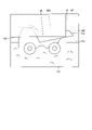
図1は、本実施形態に係る積込機械1の一例を示す側面図である。積込機械1は、作業現場において所定の作業を実施する。本実施形態においては、積込機械1がアーティキュレート積込機械の一種であるホイールローダ1であることとする。所定の作業は、掘削作業及び積込作業を含む。作業対象は、掘削対象及び積込対象を含む。ホイールローダ1は、掘削対象を掘削する掘削作業、及び掘削作業により掘削した掘削物を積込対象に積み込む積込作業を実施する。積込作業は、掘削物を排出対象に排出する排出作業を含む概念である。掘削対象として、地山、岩山、石炭、及び壁面の少なくとも一つが例示される。地山は、土砂により構成される山である。岩山は、岩又は石により構成される山である。積込対象として、運搬車両、作業現場の所定エリア、ホッパ、ベルトコンベヤ、及びクラッシャの少なくとも一つが例示される。
[Wheel loader]
FIG. 1 is a side view showing an example of a
図1に示すように、ホイールローダ1は、車体2と、運転席が設けられる運転台3と、車体2を支持する走行装置4と、車体2に支持される作業機10と、作業機10の角度を検出する角度センサ50と、トランスミッション装置30と、車体2よりも前方の計測対象を計測する三次元計測装置20と、制御装置80とを備える。
As shown in FIG. 1, the
車体2は、車体前部2Fと車体後部2Rとを含む。車体前部2Fと車体後部2Rとは、関節機構9を介して屈曲可能に連結される。
The
運転台3は、車体2に支持される。ホイールローダ1の少なくとも一部は、運転台3に搭乗した運転者によって操作される。
A
走行装置4は、車体2を支持する。走行装置4は、車輪5を有する。車輪5は、車体2に搭載されているエンジンが発生する駆動力により回転する。タイヤ6が車輪5に装着される。車輪5は、車体前部2Fに装着される2つの前輪5Fと、車体後部2Rに装着される2つの後輪5Rとを含む。タイヤ6は、前輪5Fに装着される前タイヤ6Fと、後輪5Rに装着される後タイヤ6Rとを含む。走行装置4は、地面RSを走行可能である。
The
前輪5F及び前タイヤ6Fは、回転軸FXを中心に回転可能である。後輪5R及び後タイヤ6Rは、回転軸RXを中心に回転可能である。
The
以下の説明においては、前輪5Fの回転軸FXと平行な方向を適宜、車幅方向、と称し、地面RSと接触する前タイヤ6Fの接地面と直交する方向を適宜、上下方向、と称し、車幅方向及び上下方向の両方と直交する方向を適宜、前後方向、と称する。ホイールローダ1の車体2が直進状態で走行するとき、回転軸FXと回転軸RXとは平行である。
In the following description, the direction parallel to the rotation axis FX of the
走行装置4は、駆動装置4Aと、ブレーキ装置4Bと、操舵装置4Cとを有する。駆動装置4Aは、ホイールローダ1を加速させるための駆動力を発生する。駆動装置4Aは、ディーゼルエンジンのような内燃機関を含む。駆動装置4Aで発生した駆動力がトランスミッション装置30を介して車輪5に伝達され、車輪5が回転する。ブレーキ装置4Bは、ホイールローダ1を減速又は停止させるための制動力を発生する。操舵装置4Cは、ホイールローダ1の走行方向を調整可能である。ホイールローダ1の走行方向は、車体前部2Fの向きを含む。操舵装置4Cは、油圧シリンダによって車体前部2Fを屈曲させることによって、ホイールローダ1の走行方向を調整する。
The
本実施形態において、走行装置4は、運転台3に搭乗した運転者によって操作される。作業機10は、制御装置80に制御される。走行装置4を操作する走行操作装置40が運転台3に配置される。運転者は、走行操作装置40を操作して、走行装置4を作動させる。走行操作装置40は、アクセルペダル、ブレーキペダル、ステアリングレバー、及び前後進を切り換えるためのシフトレバー41を含む。アクセルペダルが操作されることにより、ホイールローダ1の走行速度が増大する。ブレーキペダルが操作されることにより、ホイールローダ1の走行速度が減少したり走行が停止したりする。ステアリングレバーが操作されることにより、ホイールローダ1が旋回する。シフトレバー41が操作されることにより、ホイールローダ1の前進又は後進が切り換えられる。
In the present embodiment, the
トランスミッション装置30は、駆動装置4Aで発生した駆動力を車輪5に伝達する。
The
作業機10は、車体前部2Fに回動可能に連結されるブーム11と、ブーム11に回動可能に連結されるバケット12と、ベルクランク15と、リンク16とを有する。
The
ブーム11は、ブームシリンダ13が発生する動力によって作動する。ブームシリンダ13が伸縮することにより、ブーム11は上げ動作又は下げ動作する。
The
バケット12は、刃先を含む先端部12Bを有する作業部材である。バケット12は、前輪5Fよりも前方に配置される。バケット12は、ブーム11の先端部に連結される。バケット12は、バケットシリンダ14が発生する動力によって作動する。バケットシリンダ14が伸縮することにより、バケット12はダンプ動作又はチルト動作する。
バケット12のダンプ動作が実施されることにより、バケット12ですくい上げられた掘削物がバケット12から排出される。バケット12のチルト動作が実施されることにより、バケット12は掘削物をすくい取る。
The excavated material scooped up by the
角度センサ50は、作業機10の角度を検出する。角度センサ50は、ブーム11の角度を検出するブーム角度センサ51と、バケット12の角度を検出するバケット角度センサ52とを含む。ブーム角度センサ51は、例えば車体前部2Fに規定された車体座標系の基準軸に対するブーム11の角度を検出する。バケット角度センサ52は、ブーム11に対するバケット21の角度を検出する。角度センサ50は、ポテンショメータでもよいし、油圧シリンダのストロークを検出するストロークセンサでもよい。
[三次元計測装置]
三次元計測装置20は、ホイールローダ1に搭載される。三次元計測装置20は、ハウジング17に支持される。三次元計測装置20は、車体前部2Fよりも前方の計測対象を計測する。計測対象は、作業機10により掘削された掘削物が積み込まれる積込対象を含む。三次元計測装置20は、計測対象の三次元形状を計測する。三次元計測装置20は、三次元計測装置20から計測対象の表面の複数の各計測点までの相対位置を計測して、計測対象の三次元形状を計測する。制御装置80は、計測された積込対象の三次元形状に基づいて、積込対象に関するパラメータを算出する。積込対象に関するパラメータは、積込対象までの距離、積込対象の上端部の位置、及び積込対象の高さの少なくとも一つを含む。
[Three-dimensional measuring device]
A three-
ホイールローダ1と計測対象との相対位置は、ホイールローダ1と計測対象との相対距離(三次元距離)を含む。三次元計測装置20は、計測対象の表面の複数の計測点のそれぞれとの距離を計測することによって、計測対象の三次元形状及び計測対象との相対位置を計測することができる。
The relative position between the
三次元計測装置20は、レーザ計測装置の一種であるレーザレーダ21と、写真計測装置の一種であるステレオカメラ22とを含む。
The three-
レーザレーダ21で取得された計測データは、制御装置80に出力される。制御装置80は、レーザレーダ21による計測データに基づいて、計測対象の三次元形状を計測する。
Measurement data acquired by the
ステレオカメラ22は、計測対象を撮像して、計測対象を計測する。ステレオカメラ22は、第1カメラ22Aと第2カメラ22Bとを有する。第1カメラ22Aに取得された画像データ及び第2カメラ22Bに取得された画像データは、制御装置80に出力される。制御装置80は、第1カメラ22Aに取得された画像データと第2カメラ22Bに取得された画像データとに基づいてステレオ処理を実施して、計測対象の三次元形状を計測する。画像データは、計測データの一例である。
The stereo camera 22 captures an image of the measurement target and measures the measurement target. The stereo camera 22 has a first camera 22A and a second camera 22B. The image data acquired by the first camera 22A and the image data acquired by the second camera 22B are output to the
[動作]
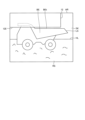
図2は、本実施形態に係るホイールローダ1の動作を示す模式図である。ホイールローダ1は、複数の作業モードで作業する。作業モードは、作業機10のバケット12で掘削対象を掘削する掘削作業モードと、掘削作業モードによりバケット12ですくい取った掘削物を積込対象に積み込む積込作業モードとを含む。掘削対象として、地面RSに置かれた地山DSが例示される。積込対象として、地面を走行可能な運搬車両LSのベッセルBEが例示される。運搬車両LSとして、ダンプトラックが例示される。
[motion]
FIG. 2 is a schematic diagram showing the operation of the
掘削作業モードにおいて、ホイールローダ1は、作業機10のバケット12に掘削物が保持されていない状態で、作業機10のバケット12で地山DSを掘削するために地山DSに向かって前進する。ホイールローダ1の運転者は、走行操作装置40を操作して、図2の矢印M1で示すように、ホイールローダ1を前進させて地山DSに接近させる。制御装置80は、バケット12で地山DSが掘削されるように、作業機10を制御する。
In the excavation work mode, the
地山DSがバケット12により掘削され、掘削物がバケット12にすくい取られた後、ホイールローダ1は、作業機10のバケット12に掘削物が保持されている状態で、地山DSから離れるように後進する。ホイールローダ1の運転者は、走行操作装置40を操作して、図2の矢印M2で示すように、ホイールローダ1を後進させて地山DSから離間させる。
After the ground DS is excavated by the
次に、積込作業モードが実施される。積込作業モードにおいて、ホイールローダ1は、作業機10のバケット12に掘削物が保持されている状態で、作業機10のバケット12により掘削された掘削物を積み込むために運搬車両LSに向かって前進する。ホイールローダ1の運転者は、走行操作装置40を操作して、図2の矢印M3で示すように、ホイールローダ1を旋回させながら前進させて運搬車両LSに接近させる。ホイールローダ1に搭載されている三次元計測装置20は、運搬車両LSを計測する。制御装置80は、三次元計測装置20の計測データに基づいて、バケット12に保持されている掘削物が運搬車両LSのベッセルBEに積み込まれるように、作業機10を制御する。すなわち、制御装置80は、ホイールローダ1が運搬車両LSに接近するように前進している状態で、ブーム11が上げ動作するように、作業機10を制御する。ブーム11が上げ動作し、バケット12がベッセルBEの上方に配置された後、制御装置80は、バケット12がチルト動作するように、作業機10を制御する。これにより、バケット12から掘削物が排出され、ベッセルBEに積み込まれる。
Next, the loading operation mode is performed. In the loading operation mode, the
バケット12から掘削物が排出され、ベッセルBEに積み込まれた後、ホイールローダ1は、作業機10のバケット12に掘削物が保持されていない状態で、運搬車両LSから離れるように後進する。運転者は、走行操作装置40を操作して、図2の矢印M4で示すように、ホイールローダ1を後進させて運搬車両LSから離間させる。
After the excavated material is discharged from the
運転者及び制御装置80は、ベッセルBEに掘削物が満載されるまで、上述の動作を繰り返す。
The operator and
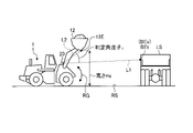
図3は、本実施形態に係るホイールローダ1の積込作業モードを示す模式図である。ホイールローダ1の運転者は、走行操作装置40を操作して、ホイールローダ1を前進させて運搬車両LSに接近させる。図3(A)に示すように、ホイールローダ1に搭載されている三次元計測装置20は、運搬車両LSの三次元形状を計測する。制御装置80は、三次元計測装置20の計測データに基づいて、ホイールローダ1と運搬車両LSとの距離及びベッセルBEの上端部の高さを検出する。ホイールローダ1から運搬車両LSまでの距離は、バケット12の先端部12Bから運搬車両LSまでの距離、バケット12の任意の点から運搬車両LSまでの距離、ホイールローダ1本体の任意の点から運搬車両LSまでの距離、及び三次元計測装置20から運搬車両LSまでの距離を含む。バケット12の先端部12Bからの距離は、先端部12Bの中央部からの距離、及び先端部12Bの両端のいずれかの点からの距離を含む。ホイールローダ1から運搬車両LSまでの距離は、バケット12の先端部12Bから車体前部2Fの進行方向に延ばして運搬車両LSと交差した点までの距離、及びバケット12の先端部12Bから運搬車両LSまでの最短距離を含む。ホイールローダ1から運搬車両LSまでの距離は、水平距離、及び地面RSと平行な方向の距離を含む。また、運搬車両LSまでの距離は、運搬車両LSの最近接点、すなわち運搬車両LSにおけるホイールローダ1側で最も近接した点までの距離を含む。
FIG. 3 is a schematic diagram showing the loading operation mode of the
図3(B)に示すように、制御装置80は、ホイールローダ1が運搬車両LSに接近するように前進している状態で、三次元計測装置20の計測データに基づいて、バケット12がベッセルBEの上端部よりも上方に配置されるように、且つ、バケット12に保持されている掘削物がバケット12からこぼれないように、バケット12の角度を制御しながら、ブーム11を上げ動作させる。
As shown in FIG. 3B, the
図3(C)に示すように、ブーム11が上げ動作し、バケット12がベッセルBEの上方に配置された後、制御装置80は、バケット12がチルト動作するように、作業機10を制御する。これにより、バケット12から掘削物が排出され、ベッセルBEに積み込まれる。
As shown in FIG. 3C, after the
[制御装置]
図4は、本実施形態に係るホイールローダ1の制御装置80を示す機能ブロック図である。制御装置80は、コンピュータシステムを含む。
[Control device]
FIG. 4 is a functional block diagram showing the
制御装置80に、作業機10、トランスミッション装置30、走行装置4、三次元計測装置20、角度センサ50、及び走行操作装置40が接続される。
The
制御装置80は、計測データ取得部81と、記憶部82と、バケット算出部83と、対象算出部86と、重複判定部84と、作業機制御部87とを有する。
The
計測データ取得部81は、三次元計測装置20の計測データを三次元計測装置20から取得する。三次元計測装置20は、計測データを制御装置80に出力する。
The measurement
また、記憶部82は、作業機データを記憶する。作業機データは、作業機10の設計データ又は諸元データを含む。作業機10の設計データは、例えば作業機10のCAD(Computer Aided Design)データを含む。作業機データは、作業機10の外形データを含む。作業機10の外形データは、作業機10の寸法データを含む。本実施形態において、作業機データは、ブーム長さ、バケット長さ、及びバケット外形を含む。ブーム長さとは、ブーム回転軸とバケット回転軸との距離をいう。バケット長さとは、バケット回転軸とバケット12の先端部12Bとの距離をいう。ブーム回転軸とは、車体前部2Fに対するブーム11の回転軸をいい、車体前部2Fとブーム11とを連結する連結ピンを含む。バケット回転軸とは、ブーム11に対するバケット12の回転軸をいい、ブーム11とバケット12とを連結する連結ピンを含む。バケット外形は、バケット12の形状及び寸法を含む。バケット12の寸法は、バケット12の左端と右端との距離を示すバケット幅、バケット12の開口部の高さ、及びバケット底面の長さなどを含む。
バケット算出部83は、角度センサ50により検出された作業機10の角度データと、記憶部82に記憶されている作業機10の作業機データとに基づいて、作業機10の位置データを算出する。バケット算出部83は、例えば車体座標系におけるバケット12の位置データを算出する。バケット算出部83は、少なくともバケット12の先端部12Bの位置、バケット12の下端部12Eの位置および高さを算出する。
対象算出部86は、計測データ取得部81により取得された計測データに基づいて、三次元計測装置20により計測されたベッセルBEを含む運搬車両LSの三次元データを算出する。運搬車両LSの三次元データは、運搬車両LSの三次元形状を示す。
The
対象算出部86は、運搬車両LSの三次元データに基づいて、運搬車両LSに関するパラメータを算出する。運搬車両LSに関するパラメータは、ホイールローダ1から運搬車両LSまでの距離、及びベッセルBEの上端部BEtの高さの少なくとも一つを含む。ベッセルBEの上端部BEtの高さは、積込対象の上端部の位置、積込対象の高さ、運搬車両LSの上端部の位置、及び運搬車両LSの高さの一例である。
The
重複判定部84は、計測データにおいてベッセル上端部BEtとバケット12とが重複しているか否かを判定する。
The overlap determination unit 84 determines whether or not the vessel upper end BEt and the
重複判定部84は、三次元計測装置20の位置と、ベッセルBEの上端部BEtの位置と、バケット12との相対位置に基づいて、ベッセル上端部BEtとバケット12とが重複しているか否かを判定する。
The overlap determination unit 84 determines whether the vessel top end BEt and the
対象算出部86は、重複判定部84においてベッセル上端部BEtとバケット12とが重複していないと判定されたときに、ベッセルBEの上端部BEtの高さを算出する。
The
本実施形態において、バケット算出部83は、ホイールローダ1の車体座標系におけるバケット12の位置を算出する。対象算出部86は、三次元計測装置20の位置と、ベッセルBEの上端部BEtの位置と、バケット12の下端部の位置とに基づいて規定される角度が所定角度以上のときに、ベッセル上端部BEtの位置を算出する。
In this embodiment, the
作業機制御部87は、対象算出部86により算出された運搬車両LSまでの距離及びベッセルBEの上端部BEtの高さに基づいて、ベッセルBEに掘削物を積み込む作業機10の動作を制御する。作業機制御部87は、重複判定部84においてベッセル上端部BEtとバケット12とが重複していないと判定されたときに、ベッセル上端部BEtの位置に基づいて、作業機10を制御する。
The work
作業機10の動作の制御は、ブームシリンダ13及びバケットシリンダ14の少なくとも一方の動作の制御を含む。ホイールローダ1は、油圧ポンプと、油圧ポンプからブームシリンダ13に供給される作動油の流量及び方向を制御するブーム制御弁と、油圧ポンプからバケットシリンダ14に供給される作動油の流量及び方向を制御するバケット制御弁とを有する。作業機制御部87は、ブーム制御弁及びバケット制御弁に制御信号を出力して、ブームシリンダ13及びバケットシリンダ14に供給される作動油の流量及び方向を制御して、ブーム11の上げ下げ動作及びバケット12の上げ下げ動作を制御することができる。
Controlling the operation of work implement 10 includes controlling the operation of at least one of
本実施形態において、対象算出部86は、バケット算出部83により算出された作業機10の位置データに基づいて、計測データから作業機10の少なくとも一部を示す部分データを除去し、部分データが除去された計測データに基づいて、ベッセル上端部BEtの高さデータ及び運搬車両LSまでの距離データを算出する。
In the present embodiment, the
本実施形態において、ホイールローダ1は、トランスミッション制御部88と、走行制御部89とを有する。
In this embodiment, the
トランスミッション制御部88は、ホイールローダ1の運転者による走行操作装置40の操作に基づいて、トランスミッション装置30の動作を制御する。トランスミッション装置30の動作の制御は、シフトチェンジの制御を含む。
The transmission control unit 88 controls the operation of the
走行制御部89は、ホイールローダ1の運転者による走行操作装置40の操作に基づいて、走行装置4の動作を制御する。走行制御部89は、駆動装置4Aを作動するためのアクセル指令、ブレーキ装置4Bを作動するためのブレーキ指令、及び操舵装置4Cを作動するためのステアリング指令を含む運転指令を出力する。
The
[作業機制御部の処理]
本実施形態において、作業機制御部87は、対象算出部86により算出されたベッセルBEの上端部の位置と、バケット算出部83により算出されたバケット12の下端部との位置とに基づいて、ベッセルBEの上端部とバケット12の下端部との相対位置が規定条件を満足するか否かを判定する。
[Processing of work machine control section]
In the present embodiment, the work implement
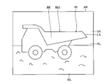
図5、図6、及び図7は、三次元計測装置20の計測範囲ARの一例として、ステレオカメラ22における計測範囲を示す図である。三次元計測装置20で計測対象を計測するとき、作業機10の少なくとも一部が三次元計測装置20の計測範囲ARに配置されてしまう可能性がある。三次元計測装置20がステレオカメラ22である場合、三次元計測装置20の計測範囲は、ステレオカメラ22の撮像範囲(ステレオカメラ22の光学系の視野領域)を含む。三次元計測装置20がレーザレーダ21である場合、三次元計測装置20の計測範囲は、レーザレーダ21から射出されるレーザ光の照射範囲を含む。
5, 6, and 7 are diagrams showing the measurement range of the stereo camera 22 as an example of the measurement range AR of the three-
規定条件は、ベッセルBEの上端部が作業機10のバケット12に遮られずに三次元計測装置20の計測範囲ARに配置される条件を含む。
The specified conditions include a condition that the upper end of vessel BE is arranged within measurement range AR of three-
図5は、バケット12が三次元計測装置20の計測範囲ARに配置され、バケット12の下端部12EがベッセルBEの上端部よりも下方に配置されている例を示す。図6に示すように、ベッセルBEの上端部とバケット12の下端部12Eとの相対位置によっては、ベッセルBEの上端部がバケット12によって隠れてしまう場合がある。
FIG. 5 shows an example in which the
図6は、バケット12が三次元計測装置20の計測範囲ARに配置されているものの、バケット12の下端部12EがベッセルBEの上端部よりも上方に配置されている例を示す。図6に示すように、ベッセルBEの上端部とバケット12の下端部12Eとの相対位置によっては、ベッセルBEの上端部がバケット12によって隠れることなく、計測範囲ARに現れる場合がある。
FIG. 6 shows an example in which the
図7は、バケット12が三次元計測装置20の計測範囲ARに配置され、バケット12の上端部12TがベッセルBEの上端部よりも下方に配置されている例を示す。図7に示すように、ベッセルBEの上端部とバケット12の上端部12Tとの相対位置によっては、ベッセルBEの上端部がバケット12によって隠れることなく、計測範囲ARに現れる場合がある。
FIG. 7 shows an example in which the
図5に示す状態の場合、作業機制御部87は、ベッセルBEの上端部とバケット12の下端部との相対位置が規定条件を満足しないと判定する。作業機制御部87は、規定条件を満足しないと判定したとき、例えば、水平方向においてホイールローダ1に最も近い運搬車両LSの部位を示す最近接点との距離に基づいて、作業機10の動作を制御する。なお、作業機制御部87は、三次元計測装置20と運搬車両LSの最近接点との距離に基づいて、ブーム11を所定の上昇速度で上昇させてもよい。
In the state shown in FIG. 5, the work implement
図6に示す状態の場合、作業機制御部87は、ベッセルBEの上端部とバケット12の下端部との相対位置が規定条件を満足すると判定する。作業機制御部87は、規定条件を満足すると判定したとき、例えばベッセルBEの上端部の高さ及びホイールローダ1と運搬車両LSの最近接点との距離に基づいて、作業機10の動作を制御する。
In the state shown in FIG. 6, the work implement
図7に示す状態の場合、作業機制御部87は、ベッセルBEの上端部とバケット12の下端部との相対位置が規定条件を満足すると判定する。作業機制御部87は、規定条件を満足すると判定したとき、例えばベッセルBEの上端部の高さ及びホイールローダ1と運搬車両LSの最近接点との距離に基づいて、作業機10の動作を制御する。
In the state shown in FIG. 7, the work implement
[規定条件の判定方法]
図8は、本実施形態に係るホイールローダ1の制御方法を示すフローチャートであって、規定条件の判定方法を含むフローチャートである。図9、図10、及び図11は、規定条件の判定方法を説明するための図である。
[Determination method of prescribed conditions]
FIG. 8 is a flowchart showing a method for controlling the
ホイールローダ1が作業機10により掘削された掘削物を積み込むために運搬車両LSに向かって前進する積込作業モードにおいて、三次元計測装置20は、少なくとも運搬車両LSを含む計測対象を計測する。三次元計測装置20の計測データは、制御装置80に出力される。計測データ取得部81は、三次元計測装置20から計測データを取得する(ステップS10)。
In a loading work mode in which the
対象算出部86は、計測データ取得部81により取得された計測データ及びバケットの位置データに基づいて、バケット先端部12Bと運搬車両LSとの距離Dbを算出する(ステップS20)。バケットの位置データであるバケット12の刃先12Bの位置は、バケット12の作業機データ及び作業機の角度データを用いて求めることができる。作業機の角度データは、角度センサ50によって検出される。作業機10の角度は、ブーム角度センサ51によって検出されるブーム11の角度と、バケット角度センサ52によって検出されるバケット12の角度とを含む。作業機10の角度を示す角度データは、バケット算出部83に出力される。
The
バケット算出部83は、作業機10の角度データと、記憶部82に記憶されている作業機10の作業機データとに基づいて、バケット12の下端部12Eの位置を算出する。バケット12の下端部12Eの位置は、例えばホイールローダ1の車体座標系において規定される(ステップS30)。バケット12の下端部12Eの位置は、予め定められている位置ではなく、三次元計測装置20から見たバケット外形の下端部の位置から特定される。
例えば図9に示すように、バケット12の下端部12EがベッセルBEの上端部BEtよりも下方に配置されている場合、図5を参照して説明したように、ベッセルBEの上端部BEtがバケット12によって隠れ、三次元計測装置20の計測範囲ARにベッセルBEの上端部BEtが配置されない。この状態では、図9における計測データ上のベッセルBEの上端部BEsがベッセル12の上端部と判断されることになるが、図9が示す通り、計測データ上のベッセルBEの上端部BEsの位置は真のベッセルBEの上端部BEtとは一致しないため、、この判断は誤りとなる。そのため、図5及び図9に示す状態の場合、作業機制御部87は、ベッセルBEの上端部BEtの位置を算出できないと判定する。
For example, as shown in FIG. 9, when the
重複判定部84は、真のベッセルBEの上端部BEtとバケット12とが重複していないか判定する。両者が重複していないと判定された場合、図10のように、計測データ上のベッセルBEの上端部BEsの位置は真のベッセルBEの上端部BEtと一致するため、計測データ上のベッセルBEの上端部BEsの高さが真のベッセルBEの上端部BEtの高さであると判定することができる。
The overlap determination unit 84 determines whether the upper end BEt of the true Bessel BE and the
例えば図10に示すように、三次元計測装置20と計測データ上のベッセルBEの上端部BEsとを結ぶ仮想線L1と、三次元計測装置20とバケットBEの下端部12Eとを結ぶ仮想線L2とがなす角度θ1が所定角度以上の場合、図6を参照して説明したように、ベッセルBEの上端部BEtは現れ、三次元計測装置20の計測範囲ARにベッセルBEの上端部BEtが配置される。図6及び図10に示す状態の場合、重複判定部84は、バケット12と運搬車両LSとが重複していないと判定することができる。一方、図9のように、角度θ1がほぼ0度である場合、真の上端部BEtがバケット12に重複している可能性が高い。この場合、重複判定部84は、真の上端部BEtを算出できないと判断する。
For example, as shown in FIG. 10, a virtual line L1 connecting the three-
対象算出部86は、計測データ取得部81により取得された計測データに基づいて、計測データ上の上端部BEsの位置を算出する。ベッセルBEの上端部BEsの位置は、例えばホイールローダ1の車体座標系において規定される(ステップS60)。
The
算出されたバケット12の下端部12Eの位置、算出された計測データ上のベッセルBEの上端部BEsの位置、及び三次元計測装置20の車体座標系における位置に基づいて、作業機制御部87は、判定角度θ1を算出する(ステップS70)。車体座標系における三次元計測装置20の位置は既知であり記憶部82に記憶されている。また、バケット12の下端部12Eの位置及び計測データ上のベッセルBEの上端部BEsの位置は、車体座標系において規定される。したがって、作業機制御部87は、判定角度θ1を算出することができる。
Based on the calculated position of the
作業機制御部87は、判定角度θが予め定められている閾値以上か否かを判定する(ステップS80)。閾値は、0[°]よりも大きい角度である。本実施形態において、閾値は、例えば5[°]である。仮想線L1と仮想線L2とがある程度離れていないと、計測データ上のベッセルBEの上端部BEsが真のベッセルBEの上端部BEtであるか判別できないためである。
The work implement
ステップS80において、判定角度θ1が閾値以上ではないと判定した場合(ステップS80:No)、作業機制御部87は、ホイールローダ1から運搬車両LSまでの距離Dbに基づいて、作業機10の動作を制御する(ステップS50)。
When it is determined in step S80 that the determination angle θ1 is not equal to or greater than the threshold value (step S80: No), the work implement
ステップS80において、判定角度θが閾値以上であると判定した場合(ステップS80:Yes)、対象算出部86は、ベッセルBEの上端部の位置に基づいて、地面RSからのベッセルBEの上端部BEtの高さHbを算出する(ステップS85)。
When it is determined in step S80 that the determination angle θ is equal to or greater than the threshold (step S80: Yes), the
作業機制御部87は、ベッセルBEの上端部の高さHb及びホイールローダ1から運搬車両LSまでの距離Dbに基づいて、作業機10の動作を制御する(ステップS90)。
The work
すなわち、図3を参照して説明したように、作業機制御部87は、ホイールローダ1が運搬車両LSに接近するように前進している状態で、対象算出部86により算出されたベッセルBEの上端部の高さ及び運搬車両LSまでの距離に基づいて、バケット12がベッセルBEの上端部よりも上方に配置されるように、且つ、バケット12に保持されている掘削物がバケット12からこぼれないように、バケット12の角度を制御しながら、ブーム11を上げ動作させる。ブーム11が上げ動作し、バケット12がベッセルBEの上方に配置された後、作業機制御部87は、バケット12がチルト動作するように、作業機10を制御する。これにより、バケット12から掘削物が排出され、ベッセルBEに積み込まれる。
That is, as described with reference to FIG. 3, the work implement
また、ホイールローダ1の走行速度及び現時点でのバケット高さも考慮してもよい。これにより、刃先12Bが運搬車両LSの最近接点に到達する直前に刃先12Bの位置がベッセルBEの上端部BEtよりも高い位置になるよう作業機10を最適な上昇速度で制御することができる。
Also, the travel speed of the
本実施形態においては、計測範囲ARにベッセルBEの上端部が現れたとしても、判定角度θ1が閾値以上になったと判定されるまで、作業機制御部87は、ベッセルBEの上端部の高さを参照せずに、ベッセルBEまでの距離のみに基づいて、作業機10を制御する。
In the present embodiment, even if the upper end of the vessel BE appears in the measurement range AR, the work implement
なお、本実施形態においては、判定角度θ1に基づいて、規定条件を満足するか否かを判定することとした。図11に示すように、バケット12が下方に位置する場合、三次元計測装置20とベッセル上端部BEtとを結ぶ仮想線L1と、三次元計測装置20とバケット上端部12Tとを結ぶ仮想線L2とのなす角度θ2が所定角度(θ1とは逆方向)以上である場合に、真のバケット上端部BEtを算出できると判定してもよい。また、バケット12が下方に位置する場合、少しでもベッセルBEが検出された場合には、図11に示されるように、計測データ上のベッセル上端BEsの位置は、真のベッセル上端部BEtと一致するため、真のバケット上端部BEtを算出できると判定してもよい。
In this embodiment, it is determined whether or not the specified condition is satisfied based on the determination angle θ1. As shown in FIG. 11, when the
重複判定部84は、計測データ上のバケット上端部BEsにおけるすべての領域がバケットと重なっている場合に重複していると判定する場合に限られず、例えば計測データ上のバケット上端部BEsにおける所定割合の領域がバケットと重なっている場合に重複していると判定してもよい。 The overlap determination unit 84 is not limited to the case where the overlap is determined when all the regions in the bucket upper end BEs on the measurement data overlap with the bucket. overlaps with the bucket, it may be determined that there is an overlap.
なお、地面RSを基準とするバケット下端部12Eの地面RSからの高さHeに基づいて、規定条件を満足するか否かが判定されてもよい。例えば、バケット下端部12Eの高さHeが、計測データ上のベッセル上端部BEsの高さよりも所定距離以上高い場合に計測データ上のベッセル上端部BEsの高さを求めるようにしてもよい。地面RSは、例えばタイヤ6の接地面に基づいて規定されてもよい。タイヤ6の接地面の位置は、例えば車体座標系において規定される既知データである。
It may be determined whether or not the specified condition is satisfied based on the height He of the bucket
なお、ホイールローダ1に慣性計測装置(IMU:Inertial Measurement Unit)又は傾斜センサが設けられている場合、慣性計測装置又は傾斜センサの検出データに基づいて、地面RSの位置が特定されてもよい。
In addition, when the
[ステレオカメラの計測データに基づくベッセルの上端部の位置の算出方法]
次に、ステレオカメラ22の計測データ上のベッセル上端部BEsの位置の算出方法について説明する。
[Method of calculating the position of the upper end of the vessel based on the measurement data of the stereo camera]
Next, a method of calculating the position of the upper end BEs of the vessel on the measurement data of the stereo camera 22 will be described.
ホイールローダ1が作業機10による掘削された掘削物を積み込むために運搬車両LSに向かって前進する積込作業モードにおいて、ステレオカメラ22は、運搬車両LSを計測する。計測データ取得部81は、ステレオカメラ22から、運搬車両LSを計測したステレオカメラ22の計測データを取得する。
In a loading operation mode in which the
ステレオカメラ22は、運搬車両LSの表面の複数の計測点PIのそれぞれとの距離を計測する。 The stereo camera 22 measures the distance to each of the plurality of measurement points PI on the surface of the transport vehicle LS.
図12は、本実施形態に係るステレオカメラ22により取得された運搬車両LSを含む画像データの一例を示す図である。図12において、バケット12を示す画像は省略する。なお、図12においては、計測点PI(点データ)を1つしか記載されていないが、図12に示す画像データの画素ごとに計測点PIが設定される。ステレオカメラ22は、画像データに対してステレオ処理を行うことにより各画素毎に対応する点群データ、すなわち三次元データを得ることができる。
FIG. 12 is a diagram showing an example of image data including the transportation vehicle LS acquired by the stereo camera 22 according to this embodiment. In FIG. 12, the image showing the
対象算出部86は、ステレオカメラ22の計測データである画像データに基づいて、車体座標系におけるステレオカメラ22から各画素に写る運搬車両LSの表面における複数の計測点PIまでの距離を算出する。算出部86は、運搬車両LSの表面の複数の計測点PIのそれぞれまでの距離に基づいて、運搬車両LSの三次元形状を算出する。
The
次に、対象算出部86は、ステレオカメラ22からの距離と、その距離を示す計測点PIのデータ数との関係を示すヒストグラムを作成する。
Next, the
図13は、ステレオカメラ22から計測点PIまでの距離と、各距離に存在する計測点PIのデータ数との関係を示すヒストグラムを示す模式図である。各距離は一定の距離は場を有するものである。 FIG. 13 is a schematic diagram showing a histogram showing the relationship between the distance from the stereo camera 22 to the measurement points PI and the number of data of the measurement points PI present at each distance. Each distance has a constant distance field.
図12に示す画像データにおいては、例えば地面のような運搬車両LS以外の計測対象が含まれているため、図13に示すように、幅広い距離においてヒストグラムのデータが存在する。一方、図12に示す画像データにおいては、運搬車両LSの側面領域が占める割合が大きい。また、運搬車両LSの側面は地面からほぼ垂直に立っており、ステレオカメラ22から運搬車両LSの側面の各計測点までの距離はほぼ一定である。そのため、ヒストグラムにおいて、ステレオカメラ22から運搬車両LSの計測点PIまでの距離において多くのデータがカウントされる。対象算出部86は、多くのデータがカウントされた距離幅に入っている三次元データを運搬車両LSの計測データと判断する。そして、運搬車両LSの計測データと判断された三次元データとバケット12の位置データとに基づき、ホイールローダ1から運搬車両LSまでの距離Dbを算出する。また、運搬車両LSの計測データと判断された三次元データに基づいて、計測データ上のバケット上端BEsの高さを算出する。
Since the image data shown in FIG. 12 includes measurement targets other than the transport vehicle LS, such as the ground, histogram data exists over a wide range of distances, as shown in FIG. On the other hand, in the image data shown in FIG. 12, the side area of the transport vehicle LS occupies a large proportion. Moreover, the side surface of the transport vehicle LS is almost perpendicular to the ground, and the distances from the stereo camera 22 to each measurement point on the side surface of the transport vehicle LS are substantially constant. Therefore, in the histogram, much data is counted in the distance from the stereo camera 22 to the measurement point PI of the transportation vehicle LS. The
作業機制御部87は、対象算出部86により算出されたベッセルBEの上端部の高さHb及び運搬車両LSまでの距離Dbに基づいて、作業機10を制御する。
The work implement
[レーザレーダの計測データに基づくベッセルの上端部の位置の算出方法]
次に、レーザレーダ21の計測データに基づくベッセルBEの上端部の位置の算出方法について説明する。
[Method of calculating the position of the upper end of the vessel based on the measurement data of the laser radar]
Next, a method of calculating the position of the upper end of the vessel BE based on the measurement data of the
図14は、レーザレーダ21による計測方法を模式的に示す。なお、図14においてバケット12を示す図は省略する。図14に示すように、レーザレーダ21は、運搬車両LSの表面の複数の照射点PJのそれぞれとの距離を計測する。計測データ取得部81は、各照射点PJの位置データからなる三次元データを取得する。対象算出部86は、計測された三次元データを地面グループと運搬車両グループとに分割する。
FIG. 14 schematically shows a measurement method using the
対象算出部86は、運搬車両グループにおける三次元データと作業機の位置データとから、ホイールローダ1から運搬車両LSまでの距離Dbを算出する。
The
対象算出部86は、運搬車両グループにおける三次元データのうち最も高い位置に存在する照射点PJを抽出し、この照射点PJに基づいて、ベッセル上端部BEtの高さHbを算出する。
The
[効果]
以上説明したように、本実施形態によれば、ベッセルBEの上端部とバケット12の下端部との相対位置が規定条件を満足するときに、作業機制御部87は、ベッセルBEの上端部の位置およびホイールローダ1から運搬車両LSまでの距離に基づいて、作業機10を制御する。ベッセルBEの上端部がバケット12に隠れてしまっている状態においては、対象算出部86によって算出される計測データ上のベッセル上端部BEsの位置は、真のベッセル上端部BEtと一致していない可能性が高い。本実施形態においては、作業機制御部87は、ベッセルBEの上端部がバケット12に遮られずに三次元計測装置20の計測範囲ARに配置される規定条件を満足するときに、対象算出部86により算出されたベッセルBEの上端部の位置に基づいて、作業機10を制御する。これにより、作業機制御部87は、高精度に算出されたベッセルBEの上端部の位置に基づいて、作業機10を制御することができる。また、作業機制御部87は、規定条件を満足しないときに、ベッセルBEの上端部の位置を参照することなく、作業機10を制御する。これにより、作業機制御部87は、不正確な計測データに基づいて、作業機10を制御することを防ぐことができる。
[effect]
As described above, according to the present embodiment, when the relative position between the upper end of the vessel BE and the lower end of the
[コンピュータシステム]
図15は、コンピュータシステム1000の一例を示すブロック図である。上述の制御装置80は、コンピュータシステム1000によって構成される。コンピュータシステム1000は、CPU(Central Processing Unit)のようなプロセッサ1001と、ROM(Read Only Memory)のような不揮発性メモリ及びRAM(Random Access Memory)のような揮発性メモリを含むメインメモリ1002と、ストレージ1003と、入出力回路を含むインターフェース1004とを有する。上述の制御装置80の機能は、プログラムとしてストレージ1003に記憶されている。プロセッサ1001は、プログラムをストレージ1003から読み出してメインメモリ1002に展開し、プログラムに従って上述の処理を実行する。なお、プログラムは、ネットワークを介してコンピュータシステム1000に配信されてもよい。
[Computer system]
FIG. 15 is a block diagram showing an example of a
[その他の実施形態]
なお、上述の実施形態においては、三次元計測装置20としてレーザレーダ21及びステレオカメラ22の両方がホイールローダ1に設けられることとした。レーザレーダ21及びステレオカメラ22の一方がホイールローダ1に設けられてもよい。また、三次元計測装置20は、作業対象の三次元形状及び作業対象との相対位置を計測できればよく、レーザレーダ21及びステレオカメラ22に限定されない。
[Other embodiments]
In the above-described embodiment, the
上述の実施形態において、三次元計測装置20に代えて、計測装置としての撮像装置を用いて計測対象の画像を取得して、人工知能(AI:Artificial Intelligence)などの画像認識によりバケット12がベッセルBEの上端部に重なっているか否かが判定されてもよい。また、三次元計測装置20によって計測された三次元データに基づいて、AIなどによる解析によって、バケット12とベッセルBEの上端部との重なりを判定してもよい。
In the above-described embodiment, instead of the three-
上述の実施形態において、計測データ上のベッセル上端部BEsがバケット12によって隠れているか否かを判定したが、その形態に限られず、例えば計測データ上の運搬車両LS全体がバケット12によって隠れているか否かを判定し、例えば計測データ上の運搬車両LS全体の領域に対して所定割合よりも大きい領域がバケット12によって重複している場合に、作業機制御部87が作業機の制御を行わず、運搬車両LS全体の領域に対して、所定割合以下の領域だけバケットと重複していると判定されたときに、計測された前記積込対象の位置に基づいて、前記作業機を制御する、としてもよい。
In the above-described embodiment, it is determined whether or not the vessel upper end BEs on the measurement data is hidden by the
上述の実施形態において、計測データ上のベッセル上端部BEsがバケット12によって隠れていると判定された場合に、運搬車両LSまでの距離Dbに基づいて作業機10を制御するようにしたが、その形態に限られず、例えば計測データ上のベッセル上端部BEsがバケット12によって隠れていると判定された場合に、作業機の制御を行わない、または所定の上昇速度で作業来10を上昇するよう制御するようにしてもよい。
In the above embodiment, when it is determined that the vessel upper end BEs on the measurement data is hidden by the
または、対象算出部86は、図11のような状態において計測されたベッセル上端部BEtの高さHbを記憶部82に記憶させておき、図9のような状態においてベッセル上端部BEtがバケット12によって隠れていると判定された場合であっても、記憶されたベッセル上端部BEtの高さHbに基づいて、作業機10を制御するようにしてもよい。
Alternatively, the
なお、上述の各実施形態において、ホイールローダ1が作業を実施する作業現場は、鉱山の採掘現場でもよいし、施工現場又は建設現場でもよい。
In each of the above-described embodiments, the work site where the
なお、ホイールローダ1は、除雪作業に使用されてもよいし、農畜産業における作業に使用されてもよいし、林業における作業に使用されてもよい。
Note that the
なお、上述の実施形態において、バケット12は、複数の刃を有してもよいし、ストレート状の刃先を有してもよい。
In addition, in the above-described embodiment, the
なお、ブーム11の先端部に連結される作業部材は、バケット12でなくてもよく、除雪作業に使用されるスノープラウ又はスノーバケットでもよいし、農畜産業の作業において使用されるベールグラブ又はフォークでもよいし、林業の作業において使用されるフォーク又はバケットでもよい。
The work member connected to the tip of the
なお、作業機械は、ホイールローダに限定されず、例えば油圧ショベル又はブルドーザのような作業機を有する作業機械に上述の実施形態で説明した制御装置80及び制御方法を適用することができる。
The working machine is not limited to a wheel loader, and the
1…ホイールローダ(積込機械)、2…車体、2F…車体前部、2R…車体後部、3…運転台、4…走行装置、4A…駆動装置、4B…ブレーキ装置、4C…操舵装置、5…車輪、5F…前輪、5R…後輪、6…タイヤ、6F…前タイヤ、6R…後タイヤ、7…フロントフェンダ、7A…第1部材、7B…第2部材、8…前照灯、9…関節機構、10…作業機、11…ブーム、12…バケット、12B…先端部、12E…下端部、13…ブームシリンダ、14…バケットシリンダ、15…ベルクランク、16…リンク、20…三次元計測装置、21…レーザレーダ、22…ステレオカメラ、22A…第1カメラ、22B…第2カメラ、30…トランスミッション装置、40…走行操作装置、50…角度センサ、51…ブーム角度センサ、52…バケット角度センサ、80…制御装置、81…計測データ取得部、82…記憶部、83…バケット算出部、86…対象算出部、87…作業機制御部、88…トランスミッション制御部、89…走行制御部、AR…計測範囲、BE…ベッセル(積込対象)、DA…分割データ、DS…地山(掘削対象)、FX…回転軸、LS…運搬車両、PJ…照射点、RX…回転軸、RS…地面、SH…閾値。
DESCRIPTION OF
Claims (8)
前記計測データに基づいて、前記車体よりも前方の前記作業機のバケットにより掘削された掘削物が積み込まれる積込対象の上端部の位置を算出する対象算出部と、
前記バケットの位置データを算出するバケット算出部と、
側面から見た真の積込対象の上端部と前記バケットとが重複しているか否かを判定する重複判定部と、
前記重複せずに前記積込対象の上端部が前記バケットに遮られずに前記計測装置の計測範囲に配置される規定条件を満足するときに、前記対象算出部により算出された前記積込対象の上端部の位置に基づいて、前記作業機を制御し、前記重複して前記規定条件を満足しないときに、前記積込対象の上端部の位置を参照することなく前記作業機を制御する又は前記作業機を制御しない作業機制御部と、を備える
積込機械の制御装置。 a measurement data acquisition unit that acquires measurement data of a measurement device that is supported by a front portion of a vehicle body of a loading machine having a working machine and that measures an object to be measured in front of the vehicle body ;
an object calculation unit that calculates, based on the measurement data, a position of an upper end of an object to be loaded onto which an excavated object excavated by the bucket of the working machine is loaded ahead of the vehicle body ;
a bucket calculation unit that calculates position data of the bucket;
an overlap determination unit that determines whether or not the bucket overlaps with the upper end of the true loading target viewed from the side ;
The object to be loaded calculated by the object calculating unit when satisfying a prescribed condition that the upper end of the object to be loaded is arranged in the measurement range of the measuring device without being blocked by the bucket without overlapping. controlling the working machine based on the position of the upper end of the object, and controlling the working machine without referring to the position of the upper end of the object to be loaded when the prescribed condition is not satisfied in duplicate, or and a work machine control unit that does not control the work machine.
前記対象算出部は、前記計測装置と、前記積込対象の上端部と、前記バケットの下端部とに基づいて規定される角度が所定角度以上のときに、前記積込対象の上端部の位置を算出する、
請求項1に記載の積込機械の制御装置。 The bucket calculator calculates the position of the lower end of the bucket,
The object calculation unit determines the position of the upper end of the object to be loaded when an angle defined based on the measuring device, the upper end of the object to be loaded, and the lower end of the bucket is equal to or greater than a predetermined angle. to calculate
A control device for a loading machine according to claim 1 .
前記作業機制御部は、前記真の積込対象の上端部と前記バケットとが重複していないと判定された場合に、前記積込対象の上端部の位置及び前記距離に基づいて、前記作業機を制御し、前記真の積込対象の上端部と前記バケットとが重複していると判定された場合に、前記距離に基づいて、前記作業機を制御する、
請求項1又は請求項2に記載の積込機械の制御装置。 The object calculation unit calculates a distance from the loading machine to the object to be loaded based on the measurement data and the position data of the bucket,
When it is determined that the upper end of the true object to be loaded and the bucket do not overlap, the work machine control unit controls the work machine based on the position and the distance of the upper end of the object to be loaded. and controlling the working machine based on the distance when it is determined that the upper end of the true loading target and the bucket overlap,
A control device for a loading machine according to claim 1 or 2 .
前記計測データは、画像データを含み、
前記重複判定部は、前記画像データに基づく画像解析により前記重複しているか否かを判定する、
請求項1から請求項3のいずれか一項に記載の積込機械の制御装置。 The measurement device includes an imaging device,
The measurement data includes image data,
The overlap determination unit determines whether or not there is an overlap by image analysis based on the image data.
A control device for a loading machine according to any one of claims 1 to 3 .
前記計測データに基づいて、前記車体よりも前方の前記作業機のバケットにより掘削された掘削物が積み込まれる積込対象の位置を算出する対象算出部と、
前記バケットの位置データを算出するバケット算出部と、
側面から見た前記計測データにおいて前記積込対象と前記バケットとが重複しているか否かを判定する重複判定部と、
前記計測データ上の前記積込対象の全体の領域に対して、所定割合よりも大きくバケットと重複していると判定されたときに、前記作業機を制御せず、前記計測データ上の前記積込対象の全体の領域に対して、所定割合未満だけバケットと重複していると判定されたときに、前記対象算出部により算出された前記積込対象の位置に基づいて、前記作業機を制御する作業機制御部と、を備える
積込機械の制御装置。 a measurement data acquisition unit that acquires measurement data of a measurement device that is supported by a front portion of a vehicle body of a loading machine having a working machine and that measures an object to be measured in front of the vehicle body ;
a target calculation unit that calculates, based on the measurement data, a position of a loading target on which an excavated material excavated by the bucket of the working machine ahead of the vehicle body is loaded;
a bucket calculation unit that calculates position data of the bucket;
an overlap determination unit that determines whether or not the object to be loaded and the bucket overlap in the measurement data viewed from the side ;
When it is determined that the bucket overlaps with the entire area of the object to be loaded on the measurement data by more than a predetermined ratio, the work machine is not controlled, and the load on the measurement data is not controlled. The work machine is controlled based on the position of the object to be loaded calculated by the object calculation unit when it is determined that the entire region to be loaded overlaps the bucket by less than a predetermined ratio. and a work machine control unit that controls the loading machine.
前記計測データに基づいて、前記車体よりも前方の前記作業機のバケットにより掘削された掘削物が積み込まれる積込対象の上端部の位置を算出する対象算出部と、
前記バケットの位置データを算出するバケット算出部と、
側面から見た真の積込対象の上端部と前記バケットとが重複しているか否かを判定する重複判定部と、
前記重複せずに前記積込対象の上端部が前記バケットに遮られずに前記計測装置の計測範囲に配置される規定条件を満足するときに、前記対象算出部により算出された前記積込対象の上端部の位置に基づいて、前記作業機を制御し、前記重複して前記規定条件を満足しないときに、前記積込対象の上端部の位置を参照することなく前記作業機を制御する又は前記作業機を制御しない作業機制御部と、を備え、
前記対象算出部は、前記真の積込対象の上端部と前記バケットとが重複していないと判定された場合に、前記積込対象の上端部の位置を記憶し、
前記作業機制御部は、真の前記積込対象の上端部と前記バケットとが重複していると判定された場合に、記憶された前記積込対象の上端部の位置に基づいて、前記作業機を制御する、
積込機械の制御装置。 a measurement data acquisition unit that acquires measurement data of a measurement device that is supported by a front portion of a vehicle body of a loading machine having a working machine and that measures an object to be measured in front of the vehicle body ;
an object calculation unit that calculates, based on the measurement data, a position of an upper end of an object to be loaded onto which an excavated object excavated by the bucket of the working machine is loaded ahead of the vehicle body ;
a bucket calculation unit that calculates position data of the bucket;
an overlap determination unit that determines whether or not the bucket overlaps with the upper end of the true loading target viewed from the side ;
The object to be loaded calculated by the object calculating unit when satisfying a specified condition that the upper end of the object to be loaded is arranged in the measurement range of the measuring device without being blocked by the bucket without overlapping. controlling the working machine based on the position of the upper end of the object, and controlling the working machine without referring to the position of the upper end of the object to be loaded when the specified condition is not satisfied in duplicate, or a work machine control unit that does not control the work machine,
The object calculation unit stores the position of the upper end of the object to be loaded when it is determined that the upper end of the true object to be loaded and the bucket do not overlap,
When it is determined that the bucket overlaps with the true upper end of the object to be loaded, the work machine control unit controls the work machine based on the stored position of the upper end of the object to be loaded. to control the machine,
Control device for the loading machine.
前記計測データに基づいて、前記車体よりも前方の前記作業機のバケットにより掘削された掘削物が積み込まれる積込対象の上端部の位置を算出することと、
前記バケットの位置データを算出することと、
側面から見た真の積込対象の上端部と前記バケットとが重複しているか否かを判定することと、
前記重複せずに前記積込対象の上端部が前記バケットに遮られずに前記計測装置の計測範囲に配置される規定条件を満足するときに、前記算出された前記積込対象の上端部の位置に基づいて、前記作業機を制御し、前記重複して前記規定条件を満足しないときに、前記積込対象の上端部の位置を参照することなく前記作業機を制御する又は前記作業機を制御しないことと、を含む
積込機械の制御方法。 Acquiring measurement data of a measuring device supported by a front portion of a vehicle body of a loading machine having a working machine and mounted on a measuring object to be measured in front of the vehicle body ;
calculating, based on the measurement data, a position of an upper end portion of an object to be loaded onto which an excavated material excavated by the bucket of the working machine ahead of the vehicle body is loaded;
calculating position data for the bucket;
Determining whether or not the bucket overlaps with the upper end of the real object to be loaded when viewed from the side ;
When the specified condition is satisfied that the upper end of the object to be loaded does not overlap and is arranged in the measurement range of the measuring device without being blocked by the bucket, the calculated upper end of the object to be loaded controlling the work machine based on the position, and controlling the work machine without referring to the position of the upper end of the object to be loaded when the specified condition is not satisfied by the duplication; A method of controlling a loading machine, including non -controlling.
請求項7に記載の積込機械の制御方法。 Determining whether or not the upper end of the true loading target viewed from the side and the bucket overlap;
A method of controlling a loading machine according to claim 7 .
Priority Applications (5)
| Application Number | Priority Date | Filing Date | Title |
|---|---|---|---|
| JP2018087775A JP7121532B2 (en) | 2018-04-27 | 2018-04-27 | LOADING MACHINE CONTROL DEVICE AND LOADING MACHINE CONTROL METHOD |
| CN201980023870.1A CN111954739B (en) | 2018-04-27 | 2019-03-11 | Control device for loading machine and control method for loading machine |
| PCT/JP2019/009791 WO2019207982A1 (en) | 2018-04-27 | 2019-03-11 | Loading machine control device and loading machine control method |
| US17/043,002 US11885096B2 (en) | 2018-04-27 | 2019-03-11 | Loading machine control device and loading machine control method |
| EP19792698.3A EP3760794A4 (en) | 2018-04-27 | 2019-03-11 | Loading machine control device and loading machine control method |
Applications Claiming Priority (1)
| Application Number | Priority Date | Filing Date | Title |
|---|---|---|---|
| JP2018087775A JP7121532B2 (en) | 2018-04-27 | 2018-04-27 | LOADING MACHINE CONTROL DEVICE AND LOADING MACHINE CONTROL METHOD |
Publications (2)
| Publication Number | Publication Date |
|---|---|
| JP2019190238A JP2019190238A (en) | 2019-10-31 |
| JP7121532B2 true JP7121532B2 (en) | 2022-08-18 |
Family
ID=68293853
Family Applications (1)
| Application Number | Title | Priority Date | Filing Date |
|---|---|---|---|
| JP2018087775A Active JP7121532B2 (en) | 2018-04-27 | 2018-04-27 | LOADING MACHINE CONTROL DEVICE AND LOADING MACHINE CONTROL METHOD |
Country Status (5)
| Country | Link |
|---|---|
| US (1) | US11885096B2 (en) |
| EP (1) | EP3760794A4 (en) |
| JP (1) | JP7121532B2 (en) |
| CN (1) | CN111954739B (en) |
| WO (1) | WO2019207982A1 (en) |
Families Citing this family (5)
| Publication number | Priority date | Publication date | Assignee | Title |
|---|---|---|---|---|
| JP7374142B2 (en) * | 2021-03-01 | 2023-11-06 | 日立建機株式会社 | wheel loader |
| CN113737886B (en) * | 2021-09-26 | 2023-02-17 | 广西柳工机械股份有限公司 | Unloading auxiliary system and method for remote control loader |
| CN113985873A (en) * | 2021-10-26 | 2022-01-28 | 吉林大学 | Planning method for shovel points of autonomous digging operation of loader |
| JP2024030581A (en) * | 2022-08-24 | 2024-03-07 | 株式会社小松製作所 | Work machines, systems including work machines, and control methods for work machines |
| JP2024030582A (en) * | 2022-08-24 | 2024-03-07 | 株式会社小松製作所 | Work machines, systems including work machines, and control methods for work machines |
Citations (8)
| Publication number | Priority date | Publication date | Assignee | Title |
|---|---|---|---|---|
| JP2000136549A (en) | 1998-10-09 | 2000-05-16 | Carnegie Mellon Univ | Autonomous excavation and truck loading system |
| JP2008248523A (en) | 2007-03-29 | 2008-10-16 | Komatsu Ltd | Working vehicle |
| WO2010104138A1 (en) | 2009-03-12 | 2010-09-16 | 株式会社小松製作所 | Construction vehicle provided with operating machine |
| WO2011074583A1 (en) | 2009-12-14 | 2011-06-23 | 日立建機株式会社 | Gear shifting control device for operation vehicle |
| WO2018043091A1 (en) | 2016-08-31 | 2018-03-08 | 株式会社小松製作所 | Wheel loader and wheel loader control method |
| WO2018043104A1 (en) | 2016-08-31 | 2018-03-08 | 株式会社小松製作所 | Wheel loader and wheel loader control method |
| US20180080193A1 (en) | 2016-09-21 | 2018-03-22 | Deere & Company | System and method for automatic dump control |
| WO2018146782A1 (en) | 2017-02-09 | 2018-08-16 | 株式会社小松製作所 | Work vehicle and display device |
Family Cites Families (17)
| Publication number | Priority date | Publication date | Assignee | Title |
|---|---|---|---|---|
| JPH1088625A (en) | 1996-09-13 | 1998-04-07 | Komatsu Ltd | Automatic excavation machine and method, and automatic loading method |
| GB2332415B (en) | 1997-12-19 | 2001-11-21 | Univ Carnegie Mellon | Sensor configuration for an earthmoving machine |
| JPH11350534A (en) * | 1997-12-19 | 1999-12-21 | Carnegie Mellon Univ | Scanning sensor equipment for earthmoving machine |
| AU9702798A (en) * | 1997-12-19 | 1999-07-08 | Carnegie Wave Energy Limited | Method and apparatus for receiving, storing, and distributing three- dimensional range data in an earthmoving environment |
| JPH11296229A (en) * | 1998-02-13 | 1999-10-29 | Komatsu Ltd | Vehicle guide device |
| WO2003033829A1 (en) * | 2001-10-18 | 2003-04-24 | Hitachi Construction Machinery Co., Ltd. | Hydraulic shovel work amount detection apparatus, work amount detection method, work amount detection result display apparatus |
| AU2012233861B2 (en) * | 2011-03-31 | 2015-03-19 | Hitachi Construction Machinery Co., Ltd. | Position adjustment assistance system for transportation machine |
| US8583361B2 (en) * | 2011-08-24 | 2013-11-12 | Modular Mining Systems, Inc. | Guided maneuvering of a mining vehicle to a target destination |
| US9823082B2 (en) * | 2011-08-24 | 2017-11-21 | Modular Mining Systems, Inc. | Driver guidance for guided maneuvering |
| US9052716B2 (en) * | 2011-10-17 | 2015-06-09 | Hitachi Construction Machinery Co., Ltd. | System for indicating parking position and direction of dump truck and hauling system |
| CN103857851B (en) | 2011-10-19 | 2016-03-09 | 住友重机械工业株式会社 | The control method of revolution Work machine and revolution Work machine |
| CN104024541A (en) * | 2011-12-26 | 2014-09-03 | 住友重机械工业株式会社 | Image display apparatus for shovel |
| US20140338235A1 (en) * | 2013-05-16 | 2014-11-20 | Caterpillar Global Mining Llc | Load release height control system for excavators |
| CN106795705B (en) | 2014-10-13 | 2019-05-28 | 山特维克矿山工程机械有限公司 | For controlling the arrangement of work mechanism |
| JP6345080B2 (en) * | 2014-10-30 | 2018-06-20 | 日立建機株式会社 | Work machine turning support device |
| JP6428928B2 (en) | 2015-04-23 | 2018-11-28 | 日産自動車株式会社 | Occlusion controller |
| CN107532410B (en) * | 2015-08-24 | 2020-10-13 | 株式会社小松制作所 | Control system of wheel loader and control method thereof |
-
2018
- 2018-04-27 JP JP2018087775A patent/JP7121532B2/en active Active
-
2019
- 2019-03-11 US US17/043,002 patent/US11885096B2/en active Active
- 2019-03-11 EP EP19792698.3A patent/EP3760794A4/en active Pending
- 2019-03-11 CN CN201980023870.1A patent/CN111954739B/en active Active
- 2019-03-11 WO PCT/JP2019/009791 patent/WO2019207982A1/en unknown
Patent Citations (8)
| Publication number | Priority date | Publication date | Assignee | Title |
|---|---|---|---|---|
| JP2000136549A (en) | 1998-10-09 | 2000-05-16 | Carnegie Mellon Univ | Autonomous excavation and truck loading system |
| JP2008248523A (en) | 2007-03-29 | 2008-10-16 | Komatsu Ltd | Working vehicle |
| WO2010104138A1 (en) | 2009-03-12 | 2010-09-16 | 株式会社小松製作所 | Construction vehicle provided with operating machine |
| WO2011074583A1 (en) | 2009-12-14 | 2011-06-23 | 日立建機株式会社 | Gear shifting control device for operation vehicle |
| WO2018043091A1 (en) | 2016-08-31 | 2018-03-08 | 株式会社小松製作所 | Wheel loader and wheel loader control method |
| WO2018043104A1 (en) | 2016-08-31 | 2018-03-08 | 株式会社小松製作所 | Wheel loader and wheel loader control method |
| US20180080193A1 (en) | 2016-09-21 | 2018-03-22 | Deere & Company | System and method for automatic dump control |
| WO2018146782A1 (en) | 2017-02-09 | 2018-08-16 | 株式会社小松製作所 | Work vehicle and display device |
Also Published As
| Publication number | Publication date |
|---|---|
| EP3760794A1 (en) | 2021-01-06 |
| EP3760794A4 (en) | 2021-11-10 |
| WO2019207982A1 (en) | 2019-10-31 |
| JP2019190238A (en) | 2019-10-31 |
| CN111954739B (en) | 2022-09-27 |
| US11885096B2 (en) | 2024-01-30 |
| CN111954739A (en) | 2020-11-17 |
| US20210010225A1 (en) | 2021-01-14 |
Similar Documents
| Publication | Publication Date | Title |
|---|---|---|
| JP7121532B2 (en) | LOADING MACHINE CONTROL DEVICE AND LOADING MACHINE CONTROL METHOD | |
| JP7154026B2 (en) | Working machine control device, excavating machine control device, and working machine control method | |
| JP7368536B2 (en) | working machine | |
| JP7141843B2 (en) | WORKING MACHINE CONTROL DEVICE AND WORKING MACHINE CONTROL METHOD | |
| CN112424427B (en) | Control device and control method for working machine | |
| US11821168B2 (en) | Control device for loading machine and control method for loading machine | |
| WO2022196639A1 (en) | Abnormality determination system for work machine and abnormality determination method for work machine | |
| WO2022196641A1 (en) | Working machine control system, and working machine control method |
Legal Events
| Date | Code | Title | Description |
|---|---|---|---|
| A621 | Written request for application examination |
Free format text: JAPANESE INTERMEDIATE CODE: A621 Effective date: 20210301 |
|
| A131 | Notification of reasons for refusal |
Free format text: JAPANESE INTERMEDIATE CODE: A131 Effective date: 20210831 |
|
| A521 | Request for written amendment filed |
Free format text: JAPANESE INTERMEDIATE CODE: A523 Effective date: 20211029 |
|
| A02 | Decision of refusal |
Free format text: JAPANESE INTERMEDIATE CODE: A02 Effective date: 20220125 |
|
| A521 | Request for written amendment filed |
Free format text: JAPANESE INTERMEDIATE CODE: A523 Effective date: 20220421 |
|
| C60 | Trial request (containing other claim documents, opposition documents) |
Free format text: JAPANESE INTERMEDIATE CODE: C60 Effective date: 20220421 |
|
| A911 | Transfer to examiner for re-examination before appeal (zenchi) |
Free format text: JAPANESE INTERMEDIATE CODE: A911 Effective date: 20220509 |
|
| C21 | Notice of transfer of a case for reconsideration by examiners before appeal proceedings |
Free format text: JAPANESE INTERMEDIATE CODE: C21 Effective date: 20220510 |
|
| TRDD | Decision of grant or rejection written | ||
| A01 | Written decision to grant a patent or to grant a registration (utility model) |
Free format text: JAPANESE INTERMEDIATE CODE: A01 Effective date: 20220712 |
|
| A61 | First payment of annual fees (during grant procedure) |
Free format text: JAPANESE INTERMEDIATE CODE: A61 Effective date: 20220805 |
|
| R150 | Certificate of patent or registration of utility model |
Ref document number: 7121532 Country of ref document: JP Free format text: JAPANESE INTERMEDIATE CODE: R150 |