WO2018042796A1 - レーザ照射装置、レーザ照射方法、及び半導体装置の製造方法 - Google Patents
レーザ照射装置、レーザ照射方法、及び半導体装置の製造方法 Download PDFInfo
- Publication number
- WO2018042796A1 WO2018042796A1 PCT/JP2017/020640 JP2017020640W WO2018042796A1 WO 2018042796 A1 WO2018042796 A1 WO 2018042796A1 JP 2017020640 W JP2017020640 W JP 2017020640W WO 2018042796 A1 WO2018042796 A1 WO 2018042796A1
- Authority
- WO
- WIPO (PCT)
- Prior art keywords
- processed
- region
- levitation
- gas
- laser irradiation
- Prior art date
- Legal status (The legal status is an assumption and is not a legal conclusion. Google has not performed a legal analysis and makes no representation as to the accuracy of the status listed.)
- Ceased
Links
Images









Classifications
-
- H—ELECTRICITY
- H10—SEMICONDUCTOR DEVICES; ELECTRIC SOLID-STATE DEVICES NOT OTHERWISE PROVIDED FOR
- H10P—GENERIC PROCESSES OR APPARATUS FOR THE MANUFACTURE OR TREATMENT OF DEVICES COVERED BY CLASS H10
- H10P34/00—Irradiation with electromagnetic or particle radiation of wafers, substrates or parts of devices
- H10P34/40—Irradiation with electromagnetic or particle radiation of wafers, substrates or parts of devices with high-energy radiation
- H10P34/42—Irradiation with electromagnetic or particle radiation of wafers, substrates or parts of devices with high-energy radiation with electromagnetic radiation, e.g. laser annealing
-
- H—ELECTRICITY
- H10—SEMICONDUCTOR DEVICES; ELECTRIC SOLID-STATE DEVICES NOT OTHERWISE PROVIDED FOR
- H10P—GENERIC PROCESSES OR APPARATUS FOR THE MANUFACTURE OR TREATMENT OF DEVICES COVERED BY CLASS H10
- H10P72/00—Handling or holding of wafers, substrates or devices during manufacture or treatment thereof
- H10P72/04—Apparatus for manufacture or treatment
- H10P72/0428—Apparatus for mechanical treatment or grinding or cutting
-
- B—PERFORMING OPERATIONS; TRANSPORTING
- B23—MACHINE TOOLS; METAL-WORKING NOT OTHERWISE PROVIDED FOR
- B23K—SOLDERING OR UNSOLDERING; WELDING; CLADDING OR PLATING BY SOLDERING OR WELDING; CUTTING BY APPLYING HEAT LOCALLY, e.g. FLAME CUTTING; WORKING BY LASER BEAM
- B23K26/00—Working by laser beam, e.g. welding, cutting or boring
- B23K26/08—Devices involving relative movement between laser beam and workpiece
- B23K26/10—Devices involving relative movement between laser beam and workpiece using a fixed support, i.e. involving moving the laser beam
-
- B—PERFORMING OPERATIONS; TRANSPORTING
- B23—MACHINE TOOLS; METAL-WORKING NOT OTHERWISE PROVIDED FOR
- B23K—SOLDERING OR UNSOLDERING; WELDING; CLADDING OR PLATING BY SOLDERING OR WELDING; CUTTING BY APPLYING HEAT LOCALLY, e.g. FLAME CUTTING; WORKING BY LASER BEAM
- B23K26/00—Working by laser beam, e.g. welding, cutting or boring
- B23K26/02—Positioning or observing the workpiece, e.g. with respect to the point of impact; Aligning, aiming or focusing the laser beam
- B23K26/06—Shaping the laser beam, e.g. by masks or multi-focusing
- B23K26/073—Shaping the laser spot
- B23K26/0738—Shaping the laser spot into a linear shape
-
- B—PERFORMING OPERATIONS; TRANSPORTING
- B23—MACHINE TOOLS; METAL-WORKING NOT OTHERWISE PROVIDED FOR
- B23K—SOLDERING OR UNSOLDERING; WELDING; CLADDING OR PLATING BY SOLDERING OR WELDING; CUTTING BY APPLYING HEAT LOCALLY, e.g. FLAME CUTTING; WORKING BY LASER BEAM
- B23K26/00—Working by laser beam, e.g. welding, cutting or boring
- B23K26/08—Devices involving relative movement between laser beam and workpiece
- B23K26/083—Devices involving movement of the workpiece in at least one axial direction
- B23K26/0838—Devices involving movement of the workpiece in at least one axial direction by using an endless conveyor belt
-
- B—PERFORMING OPERATIONS; TRANSPORTING
- B23—MACHINE TOOLS; METAL-WORKING NOT OTHERWISE PROVIDED FOR
- B23K—SOLDERING OR UNSOLDERING; WELDING; CLADDING OR PLATING BY SOLDERING OR WELDING; CUTTING BY APPLYING HEAT LOCALLY, e.g. FLAME CUTTING; WORKING BY LASER BEAM
- B23K26/00—Working by laser beam, e.g. welding, cutting or boring
- B23K26/36—Removing material
- B23K26/38—Removing material by boring or cutting
-
- B—PERFORMING OPERATIONS; TRANSPORTING
- B23—MACHINE TOOLS; METAL-WORKING NOT OTHERWISE PROVIDED FOR
- B23K—SOLDERING OR UNSOLDERING; WELDING; CLADDING OR PLATING BY SOLDERING OR WELDING; CUTTING BY APPLYING HEAT LOCALLY, e.g. FLAME CUTTING; WORKING BY LASER BEAM
- B23K26/00—Working by laser beam, e.g. welding, cutting or boring
- B23K26/70—Auxiliary operations or equipment
- B23K26/702—Auxiliary equipment
-
- B—PERFORMING OPERATIONS; TRANSPORTING
- B23—MACHINE TOOLS; METAL-WORKING NOT OTHERWISE PROVIDED FOR
- B23K—SOLDERING OR UNSOLDERING; WELDING; CLADDING OR PLATING BY SOLDERING OR WELDING; CUTTING BY APPLYING HEAT LOCALLY, e.g. FLAME CUTTING; WORKING BY LASER BEAM
- B23K37/00—Auxiliary devices or processes, not specially adapted for a procedure covered by only one of the other main groups of this subclass
- B23K37/04—Auxiliary devices or processes, not specially adapted for a procedure covered by only one of the other main groups of this subclass for holding or positioning work
- B23K37/0408—Auxiliary devices or processes, not specially adapted for a procedure covered by only one of the other main groups of this subclass for holding or positioning work for planar work
-
- H—ELECTRICITY
- H10—SEMICONDUCTOR DEVICES; ELECTRIC SOLID-STATE DEVICES NOT OTHERWISE PROVIDED FOR
- H10P—GENERIC PROCESSES OR APPARATUS FOR THE MANUFACTURE OR TREATMENT OF DEVICES COVERED BY CLASS H10
- H10P14/00—Formation of materials, e.g. in the shape of layers or pillars
- H10P14/20—Formation of materials, e.g. in the shape of layers or pillars of semiconductor materials
-
- H—ELECTRICITY
- H10—SEMICONDUCTOR DEVICES; ELECTRIC SOLID-STATE DEVICES NOT OTHERWISE PROVIDED FOR
- H10P—GENERIC PROCESSES OR APPARATUS FOR THE MANUFACTURE OR TREATMENT OF DEVICES COVERED BY CLASS H10
- H10P72/00—Handling or holding of wafers, substrates or devices during manufacture or treatment thereof
- H10P72/04—Apparatus for manufacture or treatment
- H10P72/0402—Apparatus for fluid treatment
-
- H—ELECTRICITY
- H10—SEMICONDUCTOR DEVICES; ELECTRIC SOLID-STATE DEVICES NOT OTHERWISE PROVIDED FOR
- H10P—GENERIC PROCESSES OR APPARATUS FOR THE MANUFACTURE OR TREATMENT OF DEVICES COVERED BY CLASS H10
- H10P72/00—Handling or holding of wafers, substrates or devices during manufacture or treatment thereof
- H10P72/04—Apparatus for manufacture or treatment
- H10P72/0431—Apparatus for thermal treatment
-
- H—ELECTRICITY
- H10—SEMICONDUCTOR DEVICES; ELECTRIC SOLID-STATE DEVICES NOT OTHERWISE PROVIDED FOR
- H10P—GENERIC PROCESSES OR APPARATUS FOR THE MANUFACTURE OR TREATMENT OF DEVICES COVERED BY CLASS H10
- H10P72/00—Handling or holding of wafers, substrates or devices during manufacture or treatment thereof
- H10P72/04—Apparatus for manufacture or treatment
- H10P72/0431—Apparatus for thermal treatment
- H10P72/0436—Apparatus for thermal treatment mainly by radiation
-
- H—ELECTRICITY
- H10—SEMICONDUCTOR DEVICES; ELECTRIC SOLID-STATE DEVICES NOT OTHERWISE PROVIDED FOR
- H10P—GENERIC PROCESSES OR APPARATUS FOR THE MANUFACTURE OR TREATMENT OF DEVICES COVERED BY CLASS H10
- H10P72/00—Handling or holding of wafers, substrates or devices during manufacture or treatment thereof
- H10P72/30—Handling or holding of wafers, substrates or devices during manufacture or treatment thereof for conveying, e.g. between different workstations
- H10P72/32—Handling or holding of wafers, substrates or devices during manufacture or treatment thereof for conveying, e.g. between different workstations between different workstations
- H10P72/3208—Changing the direction of the conveying path
-
- H—ELECTRICITY
- H10—SEMICONDUCTOR DEVICES; ELECTRIC SOLID-STATE DEVICES NOT OTHERWISE PROVIDED FOR
- H10P—GENERIC PROCESSES OR APPARATUS FOR THE MANUFACTURE OR TREATMENT OF DEVICES COVERED BY CLASS H10
- H10P72/00—Handling or holding of wafers, substrates or devices during manufacture or treatment thereof
- H10P72/30—Handling or holding of wafers, substrates or devices during manufacture or treatment thereof for conveying, e.g. between different workstations
- H10P72/33—Handling or holding of wafers, substrates or devices during manufacture or treatment thereof for conveying, e.g. between different workstations into and out of processing chamber
- H10P72/3302—Mechanical parts of transfer devices
-
- H—ELECTRICITY
- H10—SEMICONDUCTOR DEVICES; ELECTRIC SOLID-STATE DEVICES NOT OTHERWISE PROVIDED FOR
- H10P—GENERIC PROCESSES OR APPARATUS FOR THE MANUFACTURE OR TREATMENT OF DEVICES COVERED BY CLASS H10
- H10P72/00—Handling or holding of wafers, substrates or devices during manufacture or treatment thereof
- H10P72/30—Handling or holding of wafers, substrates or devices during manufacture or treatment thereof for conveying, e.g. between different workstations
- H10P72/33—Handling or holding of wafers, substrates or devices during manufacture or treatment thereof for conveying, e.g. between different workstations into and out of processing chamber
- H10P72/3314—Continuous loading and unloading into and out of a processing chamber, e.g. transporting belts within processing chambers
-
- H—ELECTRICITY
- H10—SEMICONDUCTOR DEVICES; ELECTRIC SOLID-STATE DEVICES NOT OTHERWISE PROVIDED FOR
- H10P—GENERIC PROCESSES OR APPARATUS FOR THE MANUFACTURE OR TREATMENT OF DEVICES COVERED BY CLASS H10
- H10P72/00—Handling or holding of wafers, substrates or devices during manufacture or treatment thereof
- H10P72/30—Handling or holding of wafers, substrates or devices during manufacture or treatment thereof for conveying, e.g. between different workstations
- H10P72/36—Handling or holding of wafers, substrates or devices during manufacture or treatment thereof for conveying, e.g. between different workstations using air tracks
-
- H—ELECTRICITY
- H10—SEMICONDUCTOR DEVICES; ELECTRIC SOLID-STATE DEVICES NOT OTHERWISE PROVIDED FOR
- H10P—GENERIC PROCESSES OR APPARATUS FOR THE MANUFACTURE OR TREATMENT OF DEVICES COVERED BY CLASS H10
- H10P72/00—Handling or holding of wafers, substrates or devices during manufacture or treatment thereof
- H10P72/70—Handling or holding of wafers, substrates or devices during manufacture or treatment thereof for supporting or gripping
-
- H—ELECTRICITY
- H10—SEMICONDUCTOR DEVICES; ELECTRIC SOLID-STATE DEVICES NOT OTHERWISE PROVIDED FOR
- H10P—GENERIC PROCESSES OR APPARATUS FOR THE MANUFACTURE OR TREATMENT OF DEVICES COVERED BY CLASS H10
- H10P72/00—Handling or holding of wafers, substrates or devices during manufacture or treatment thereof
- H10P72/70—Handling or holding of wafers, substrates or devices during manufacture or treatment thereof for supporting or gripping
- H10P72/76—Handling or holding of wafers, substrates or devices during manufacture or treatment thereof for supporting or gripping using mechanical means, e.g. clamps or pinches
- H10P72/7604—Handling or holding of wafers, substrates or devices during manufacture or treatment thereof for supporting or gripping using mechanical means, e.g. clamps or pinches the wafers being placed on a susceptor, stage or support
- H10P72/7612—Handling or holding of wafers, substrates or devices during manufacture or treatment thereof for supporting or gripping using mechanical means, e.g. clamps or pinches the wafers being placed on a susceptor, stage or support characterised by lifting arrangements, e.g. lift pins
-
- B—PERFORMING OPERATIONS; TRANSPORTING
- B23—MACHINE TOOLS; METAL-WORKING NOT OTHERWISE PROVIDED FOR
- B23K—SOLDERING OR UNSOLDERING; WELDING; CLADDING OR PLATING BY SOLDERING OR WELDING; CUTTING BY APPLYING HEAT LOCALLY, e.g. FLAME CUTTING; WORKING BY LASER BEAM
- B23K2101/00—Articles made by soldering, welding or cutting
- B23K2101/18—Sheet panels
-
- B—PERFORMING OPERATIONS; TRANSPORTING
- B23—MACHINE TOOLS; METAL-WORKING NOT OTHERWISE PROVIDED FOR
- B23K—SOLDERING OR UNSOLDERING; WELDING; CLADDING OR PLATING BY SOLDERING OR WELDING; CUTTING BY APPLYING HEAT LOCALLY, e.g. FLAME CUTTING; WORKING BY LASER BEAM
- B23K2101/00—Articles made by soldering, welding or cutting
- B23K2101/36—Electric or electronic devices
- B23K2101/40—Semiconductor devices
-
- B—PERFORMING OPERATIONS; TRANSPORTING
- B23—MACHINE TOOLS; METAL-WORKING NOT OTHERWISE PROVIDED FOR
- B23K—SOLDERING OR UNSOLDERING; WELDING; CLADDING OR PLATING BY SOLDERING OR WELDING; CUTTING BY APPLYING HEAT LOCALLY, e.g. FLAME CUTTING; WORKING BY LASER BEAM
- B23K2103/00—Materials to be soldered, welded or cut
- B23K2103/16—Composite materials
- B23K2103/166—Multilayered materials
- B23K2103/172—Multilayered materials wherein at least one of the layers is non-metallic
-
- B—PERFORMING OPERATIONS; TRANSPORTING
- B23—MACHINE TOOLS; METAL-WORKING NOT OTHERWISE PROVIDED FOR
- B23K—SOLDERING OR UNSOLDERING; WELDING; CLADDING OR PLATING BY SOLDERING OR WELDING; CUTTING BY APPLYING HEAT LOCALLY, e.g. FLAME CUTTING; WORKING BY LASER BEAM
- B23K2103/00—Materials to be soldered, welded or cut
- B23K2103/50—Inorganic materials other than metals or composite materials
-
- B—PERFORMING OPERATIONS; TRANSPORTING
- B65—CONVEYING; PACKING; STORING; HANDLING THIN OR FILAMENTARY MATERIAL
- B65G—TRANSPORT OR STORAGE DEVICES, e.g. CONVEYORS FOR LOADING OR TIPPING, SHOP CONVEYOR SYSTEMS OR PNEUMATIC TUBE CONVEYORS
- B65G51/00—Conveying articles through pipes or tubes by fluid flow or pressure; Conveying articles over a flat surface, e.g. the base of a trough, by jets located in the surface
- B65G51/02—Directly conveying the articles, e.g. slips, sheets, stockings, containers or workpieces, by flowing gases
- B65G51/03—Directly conveying the articles, e.g. slips, sheets, stockings, containers or workpieces, by flowing gases over a flat surface or in troughs
Definitions
- the present invention relates to a laser irradiation apparatus, a laser irradiation method, and a semiconductor device manufacturing method, and more particularly, to a laser irradiation apparatus, a laser irradiation method, and a semiconductor device manufacturing method including a floating unit that floats and conveys an object to be processed.
- Patent Document 1 discloses a laser annealing apparatus that irradiates a laser beam while floating and transporting a substrate using a gas levitation apparatus.
- the laser irradiation apparatus includes a levitation unit including a first region and a second region.
- the first region is configured to float the object to be processed using gas ejection and suction
- the second region is configured to cause the object to be treated using gas ejection without using gas suction. It is configured to float.
- a workpiece when transported using a levitation unit including a first region and a second region, gas is ejected and sucked in the first region.
- the processing object is lifted and transported, and the object to be processed is lifted and transported using gas ejection without using gas suction in the second region.
- a method of manufacturing a semiconductor device includes: (a) forming an amorphous film on a substrate; and (b) irradiating the amorphous film with laser light to form the amorphous film.
- a laser irradiation apparatus capable of reducing the deflection of the object to be processed during conveyance.
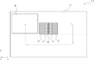
- FIG. 1 is a plan view for explaining a laser irradiation apparatus according to a first embodiment
- FIG. 2 is a cross-sectional view taken along a cutting line II-II of the laser irradiation apparatus shown in FIG. It is sectional drawing for demonstrating the relationship between the flatness of a floating unit, and the bending of a to-be-processed object. It is sectional drawing for demonstrating the state which has conveyed the to-be-processed object using the laser irradiation apparatus concerning Embodiment 1.
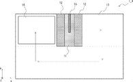
- FIG. FIG. 6 is a plan view for explaining a laser irradiation apparatus according to a second exemplary embodiment.
- FIG. 6 is a cross-sectional view taken along a cutting line VV of the laser irradiation apparatus shown in FIG. It is sectional drawing for demonstrating the structural example of a precision levitation unit. It is a top view for demonstrating the structural example of a precision levitation unit. It is sectional drawing for demonstrating the state which is conveying the to-be-processed object using a precision floating unit. It is sectional drawing for demonstrating the structural example of a rough floating unit. It is a top view for demonstrating the structural example of a rough levitation unit. It is sectional drawing for demonstrating the state which is conveying the to-be-processed object using a rough floating unit.
- FIG. 1 It is a block diagram for demonstrating an example of the piping system (air supply system) of a rough levitation unit. It is a block diagram for demonstrating an example of the piping system (air supply system) of a precision levitation unit and a semi-precision levitation unit. It is a block diagram for demonstrating an example of the piping system (exhaust system) of a precision levitation unit and a semi-precision levitation unit. It is sectional drawing for demonstrating the state which is conveying the to-be-processed object using the laser irradiation apparatus concerning Embodiment 2.
- FIG. 1 It is a block diagram for demonstrating an example of the piping system (air supply system) of a rough levitation unit. It is a block diagram for demonstrating an example of the piping system (air supply system) of a precision levitation unit and a semi-precision levitation unit. It is a block diagram for demonstrating an example of the piping system (exhaust system) of
- FIG. 1 is a plan view for explaining the laser irradiation apparatus according to the first embodiment.
- 2 is a cross-sectional view of the laser irradiation apparatus shown in FIG. 1 taken along a cutting line II-II.
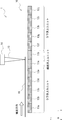
- the laser irradiation apparatus 1 includes a levitation unit 10.
- the levitation unit 10 conveys the workpiece 16 while levitation. Specifically, the laser irradiation apparatus 1 grips the workpiece 16 using the gripping unit 18 (see FIG. 1) and lifts the workpiece 16 using the levitation unit 10 to move in the transport direction (x-axis). The workpiece 16 is conveyed in the direction). When the workpiece 16 is conveyed, the levitation unit 10 adjusts the flying height so that the workpiece 16 does not come into contact with another mechanism (not shown) disposed above the workpiece 16.
- a suction cup type vacuum suction mechanism or a vacuum suction mechanism including a porous body can be used for the gripping part 18.
- the grip 18 is connected to an exhaust port (not shown), and the exhaust port is connected to an ejector, a vacuum pump, or the like. Therefore, a negative pressure for sucking gas acts on the intake port.
- the vacuum suction mechanism of the gripping part 18 is attracted to the workpiece 16.
- the gripping part 18 is conveyed by the drive mechanism of the gripping part 18 while gripping the workpiece 16. Thereby, the to-be-processed object 16 is conveyed.
- the conveyance speed of the workpiece 16 can be controlled by adjusting the conveyance speed of the drive mechanism of the grip portion 18. For example, the workpiece 16 is transported at a constant speed in a state where it is levitated above the levitation unit 10. Therefore, the workpiece 16 passes through the irradiation position of the laser light at a constant speed.
- the object 16 is irradiated with a laser beam 15 (hereinafter, the irradiation position of the laser beam is also indicated by reference numeral 15).
- the laser irradiation apparatus is a laser annealing apparatus.
- an excimer laser or the like can be used for the laser generation apparatus 14.
- the laser light supplied from the laser generator 14 becomes a line shape in an optical system (not shown), and a laser beam 15 (line beam) whose line 16 is formed on the object 16 to be processed, specifically, the focal point extends in the y-axis direction. Is irradiated.
- the object to be processed is, for example, an amorphous film formed on a substrate, and the amorphous film can be crystallized by irradiating the amorphous film with laser light 15 and annealing. it can.
- the levitation unit 10 is configured by using precision levitation units 11a and 11b and rough levitation units 13a to 13j.
- the area formed using the precision levitation units 11a and 11b is referred to as the precision levitation area 11a and 11b
- the area configured using the rough levitation units 13a to 13j is defined as the rough levitation area 13a to 11b. Also described as 13j.
- the precision levitation units 11a and 11b are arranged in a region (precision levitation region) including a laser beam irradiation position 15. Further, the rough levitation units 13a to 13e are arranged on the upstream side in the transport direction of the workpiece 16 (the negative side in the x-axis direction) with respect to the precision levitation units 11a and 11b. Further, the rough levitation units 13f to 13j are arranged on the downstream side in the transport direction of the workpiece 16 (the positive side in the x-axis direction) with respect to the precision levitation units 11a and 11b. As shown in FIGS.
- each of the precision levitation units 11a and 11b and the rough levitation units 13a to 13j is, for example, a rectangular unit extending in the y-axis direction. (Axial direction).
- the workpiece 16 is transported through the rough levitation units 13a to 13e, the precision levitation units 11a and 11b, and the rough levitation units 13f to 13j in this order.
- the shape of each floating unit is not limited to a rectangular shape.
- each floating unit may have a square shape.
- the precision levitation units 11a and 11b are arranged so that the focal point of the laser beam 15 (corresponding to the irradiation position 15 of the laser beam, the same applies hereinafter) and the precise levitation regions 11a and 11b overlap when viewed in plan.
- the rough levitation units 13a to 13j are arranged so that the focal point of the laser beam 15 and the rough levitation regions 13a to 13j do not overlap.
- the plan view means the case where the levitation unit 10 is viewed from the z-axis direction side as shown in FIG.
- the precision levitation units 11a and 11b are units that precisely lift and transport the object 16 to be processed, and can be transported while reducing the amount of deflection of the object 16 during transport.
- the precision levitation units 11a and 111b for example, precisely control the amount of gas ejected to levitate the object 16 to be processed.
- the precise levitation regions (precise levitation units) 11a and 11b are configured to levitate the workpiece 16 using gas ejection and suction.
- the detailed structure of the precision levitation units 11a and 11b has been specifically described with reference to FIGS.
- the rough levitation units 13a to 13j are units that levitate and convey the object 16 to be processed, and the object 16 does not need to come into contact with the rough levitation units 13a to 13j during conveyance.
- the amount of gas ejected is not controlled as precisely as the precision levitation units 11a and 11b. For this reason, the amount of deflection of the object to be processed 16 when passing through the rough levitation units 13a to 13j is larger than the amount of deflection of the object to be processed 16 when passing through the precision levitation units 11a and 11b.
- the rough levitation regions (rough levitation units) 13a to 13j are configured to levitate the object 16 using gas ejection without using gas suction. The detailed structure of the rough levitation units 13a to 13j is specifically described with reference to FIGS.
- the precision levitation units 11a and 11b are configured so that they can be conveyed while reducing the amount of deflection of the workpiece 16 during conveyance. Therefore, the precision levitation units 11a and 11b are expensive units because they have a more precise structure than the rough levitation units 13a to 13j configured to simply eject gas and transport the object 16 to be processed. For this reason, in the laser irradiation apparatus 10 according to the first embodiment, the precision levitation units 11a and 11b are arranged only in the area including the laser beam irradiation position 15, and the other areas are less expensive than the precision levitation unit. Arrangeable rough levitation units 13a to 13j are arranged.
- the flatness of the surfaces of the precision levitation units 11a and 11b facing the object to be processed 16 is smaller than the flatness of the surfaces of the rough levitation units 13a to 13j facing the object to be processed 16. It is configured as follows. As an example, the flatness of the precision levitation units 11a and 11b is 20 ⁇ m or less, and the flatness of the rough levitation units 13a to 13j is 75 ⁇ m or less.
- the precise levitation units 11a and 11b may be referred to as the precise levitation unit 11
- the rough levitation units 13a to 13j may be referred to as the rough levitation unit 13.
- the flatness of the precision levitation unit 11 can be determined by using the flying height (the flying height) of the workpiece 16 that floats on the precision levitation unit 11 and the deflection amount of the workpiece 16. It is considered that the deflection of the workpiece 16 is affected by the flying height of the workpiece 16 and the flatness of the surface of the flying unit. Here, it is considered that the flying height of the workpiece 16 is influenced by the pressure acting on the gas existing between the workpiece 16 and the floating unit.
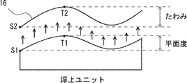
- FIG. 3 is a cross-sectional view for explaining the relationship between the flatness of the levitation unit and the deflection of the object to be processed.
- the flatness of the flying unit can be defined by the distance between the reference point S1 that is the lowest part of the flying unit and T1 that is the highest part of the flying unit.
- the deflection of the workpiece 16 can be defined by the distance between the reference point S2 that is the lowest portion of the workpiece 16 and T2 that is the highest portion of the workpiece 16.
- the object 16 is levitated so as not to collide with the levitating unit.
- the levitating amount of the object 16 is the height with the surface of the levitating unit as the zero point.
- the flatness of the surface is not reduced, the two may collide. That is, as shown in FIG. 3, it is necessary to reduce the flatness of the surface of the rough levitation unit to some extent so that the highest portion T1 of the levitation unit does not collide with the lowest portion S2 of the workpiece 16.
- the flying height of the object to be processed 16 is smaller than that of the rough levitation unit 13, and the flying height at the end of the object to be processed 16 is the lowest, so that collision with the levitation unit is avoided. Ingenuity is required. For example, if the deflection or the flying height of the workpiece 16 changes suddenly as in the vicinity of the boundary between the rough flying unit 13e and the precision flying unit 11a in FIG. 4B, the influence on the laser irradiation unit increases. Therefore, even when the precision levitation unit 11 does not have sufficient flatness, there is a possibility that the laser irradiation may be adversely affected due to the deflection of the workpiece 16. For this reason, it is necessary to reduce the flatness of the precision levitation unit 11.
- the area of the upper surface of each precision levitation unit 11. is preferably smaller than the area of the upper surface of the rough levitation unit.
- the rough levitation unit 13 levitates and conveys the workpiece 16 without colliding with the levitation unit. Therefore, the surface area of the rough levitation unit 13 can be increased as compared with the precision levitation unit 11.
- the area of the upper surface of each levitation unit has been described.
- the areas of the upper surfaces of the precision levitation units 11a and 11b and the rough levitation units 13a to 13j may be the same.
- the area of the upper surface of each levitation unit is the same in order to simplify the description.
- FIG. 4 is a cross-sectional view for explaining a state in which the workpiece 16 is being transported using the laser irradiation apparatus 1.
- FIG. 4A when the object 16 passes over the rough levitation units 13a to 13e, the amount of deflection of the object 16 increases. This is because when the object to be processed 16 is transported using the rough levitation units 13a to 13e, the object to be processed 16 does not have to come into contact with the rough levitation units 13a to 13e. This is because it is not controlled.
- the amount of deflection of the object 16 increases. This is because when the object to be processed 16 is transported using the rough levitation units 13f to 13j, it is sufficient that the object to be processed 16 does not come into contact with the rough levitation units 13f to 13j. This is because it is not controlled.
- the precision levitation units 11a and 11b are arranged in the region including the laser beam irradiation position 15 so that the amount of deflection of the workpiece 16 is reduced. . Therefore, it can suppress that it remove
- DOE focus depth
- the precision levitation units 11a and 11b are arranged only in the area including the laser light irradiation position 15, and the other areas are less expensive than the precision levitation unit.
- Arrangeable rough levitation units 13a to 13j are arranged. Therefore, the cost of the laser irradiation apparatus 1 can be reduced.
- control of the laser irradiation apparatus 1 can be simplified.
- FIG. 5 is a plan view for explaining the laser irradiation apparatus according to the second embodiment.
- 6 is a cross-sectional view of the laser irradiation apparatus shown in FIG. 5 taken along the cutting line VV.
- the laser irradiation apparatus 1 is an apparatus that irradiates the object to be processed 16 with the laser beam 15 while the object to be processed 16 is levitated using the levitation unit 10 and conveyed.
- the laser irradiation apparatus 1 includes a levitation unit 10.
- the levitation unit 10 conveys the workpiece 16 while levitation.
- the laser irradiation apparatus 1 uses the gripping unit 18 (see FIG. 5) to grip the workpiece 16 while floating the workpiece 16 using the levitation unit 10, and the conveyance direction (x-axis).
- the workpiece 16 is conveyed in the direction).
- the levitation unit 10 adjusts the flying height so that the workpiece 16 does not come into contact with another mechanism (not shown) disposed above the workpiece 16.
- a suction cup type vacuum suction mechanism or a vacuum suction mechanism including a porous body can be used for the gripping part 18.
- the grip 18 is connected to an exhaust port (not shown), and the exhaust port is connected to an ejector, a vacuum pump, or the like. Therefore, a negative pressure for sucking gas acts on the intake port.
- the vacuum suction mechanism of the gripping part 18 is attracted to the workpiece 16.
- the gripping part 18 is conveyed by the drive mechanism of the gripping part 18 while gripping the workpiece 16. Thereby, the to-be-processed object 16 is conveyed.
- the conveyance speed of the workpiece 16 can be controlled by adjusting the conveyance speed of the drive mechanism of the grip portion 18. For example, the workpiece 16 is transported at a constant speed in a state where it is levitated above the levitation unit 10. Therefore, the workpiece 16 passes through the irradiation position of the laser light at a constant speed.
- the object 16 is irradiated with a laser beam 15 (hereinafter, the irradiation position of the laser beam is also indicated by reference numeral 15).
- the laser irradiation apparatus is a laser annealing apparatus.
- an excimer laser or the like can be used for the laser generation apparatus 14.
- the laser light supplied from the laser generator 14 becomes a line shape in an optical system (not shown), and a laser beam 15 (line beam) whose line 16 is formed on the object 16 to be processed, specifically, the focal point extends in the y-axis direction. Is irradiated.
- the object to be processed is, for example, an amorphous film formed on a substrate, and the amorphous film can be crystallized by irradiating the amorphous film with laser light 15 and annealing. it can.
- the levitation unit 10 is configured using precision levitation units 11a and 11b, semi-precision levitation units 12a to 12d, and rough levitation units 13a to 13f.
- the areas formed using the precision levitation units 11a and 11b are the precision levitation areas 11a and 11b
- the areas formed using the quasi-precision levitation units 12a to 12d are quasi-precision levitation areas 12a to 12b.
- 12d, and regions formed using the rough levitation units 13a to 13f are also referred to as rough levitation regions 13a to 13f.
- the precision levitation units 11a and 11b are arranged in a region (precision levitation region) including a laser beam irradiation position 15.
- the semi-precision levitation units 12a and 12b are disposed adjacent to the precision levitation units 11a and 11b, and are upstream of the workpiece 16 in the transport direction (minus side in the x-axis direction) with respect to the precision levitation units 11a and 11b. ).
- the rough levitation units 13a to 13c are arranged so as to be adjacent to the semi-precision levitation units 12a and 12b. Side).
- the semi-precision levitation units 12c and 12d are disposed adjacent to the precision levitation units 11a and 11b, and are downstream of the workpiece 16 in the transport direction (x-axis direction) with respect to the precision levitation units 11a and 11b.
- the rough levitation units 13d to 13f are arranged so as to be adjacent to the semi-precision levitation units 12c and 12d. Side).
- the precision levitation units 11a and 11b are arranged so that the focal point of the laser beam 15 and the precision levitation regions 11a and 11b overlap when viewed in plan.
- the rough levitation units 13a to 13f are arranged so that the focal point of the laser beam 15 and the rough levitation regions 13a to 13f do not overlap.
- the plan view means the case where the levitation unit 10 is viewed from the z-axis direction side as shown in FIG.
- the semi-precise levitation units 12a and 12b are disposed between the precise levitation areas 11a and 11b and the rough levitation areas 13a to 13c.
- the semi-precise levitation units 12c and 12d are arranged between the precise levitation areas 11a and 11b and the rough levitation areas 13d to 13f.
- each of the precision levitation units 11a and 11b, the semi-precise levitation units 12a to 12d, and the rough levitation units 13a to 13f are, for example, rectangular units extending in the y-axis direction. Are arranged so as to be aligned along the transport direction (x-axis direction).
- the workpiece 16 passes through the rough levitation units 13a to 13c, the semi-precision levitation units 12a and 12b, the precision levitation units 11a and 11b, the semi-precision levitation units 12c and 12d, and the rough levitation units 13d to 13f in this order.
- the shape of each floating unit is not limited to a rectangular shape.
- each floating unit may have a square shape.
- the precision levitation units 11a and 11b are units that precisely lift and transport the object 16 to be processed, and can be transported while reducing the amount of deflection of the object 16 during transport.
- the precision levitation units 11a and 11b for example, precisely control the amount of gas ejected to levitate the object 16 to be processed.
- the precise levitation regions (precise levitation units) 11a and 11b are configured to levitate the workpiece 16 using gas ejection and suction.
- the rough levitation units 13a to 13f are units that float and convey the object 16 to be processed, and the object 16 does not need to come into contact with the rough levitation units 13a to 13f during conveyance.
- the amount of gas ejected is not controlled as precisely as the precision levitation units 11a and 11b. For this reason, the amount of deflection of the object to be processed 16 when passing through the rough levitation units 13a to 13f is larger than the amount of deflection of the object to be processed 16 when passing through the precision levitation units 11a and 11b.
- the rough levitation regions (rough levitation units) 13a to 13f are configured to levitate the object 16 using gas ejection without using gas suction.
- the semi-precision levitation units 12a and 12b are processed so that the amount of deflection of the object 16 changes smoothly when the object 16 is transported from the rough levitation units 13a to 13c to the precision levitation units 11a and 11b.
- the body 16 can be transported.
- the semi-precise levitation units 12c and 12d are configured so that the amount of deflection of the workpiece 16 changes smoothly when the workpiece 16 is transported from the precision levitation units 11a and 11b to the rough levitation units 13d to 13f.
- the workpiece 16 can be transported.
- the semi-precise levitation units 12a to 12d are between the accuracy when the precision levitation units 11a and 11b levitate the object 16 and the accuracy when the rough levitation units 13a to 13f levitate the object 16.
- the workpiece 16 is configured to float with accuracy.
- the semi-precise levitation regions (precise levitation units) 12a to 12d are configured to levitate the object 16 using gas ejection and suction.
- the amount of deflection of the object to be processed 16 when the object to be processed 16 passes over the precision levitation units 11a and 11b is the object to be processed when the object to be processed 16 passes over the rough levitation units 13a to 13c.
- the deflection amount of 16 is 1/10 to 1/20.
- the semi-precise levitation units 12a and 12b are arranged so that when the workpiece 16 is transported from the rough levitation units 13a to 13c to the precision levitation units 11a and 11b, the amount of deflection of the workpiece 16 changes smoothly. Then, the workpiece 16 is transported so as to absorb the difference between the deflection amount of the workpiece 16 in the rough levitation units 13a to 13c and the deflection amount of the workpiece 16 in the precision levitation units 11a and 11b.
- the amount of deflection of the object to be processed 16 when the object to be processed 16 passes over the precision levitation units 11a and 11b is the amount of deflection when the object to be processed 16 passes over the rough levitation units 13d to 13f. This is 1/10 to 1/20 of the deflection amount of the workpiece 16.
- the semi-precise levitation units 12c and 12d are arranged so that when the workpiece 16 is transported from the precision levitation units 11a and 11b to the rough levitation units 13d to 13f, the deflection amount of the workpiece 16 changes smoothly. Then, the workpiece 16 is transported so as to absorb the difference between the deflection amount of the workpiece 16 in the precision levitation units 11a and 11b and the deflection amount of the workpiece 16 in the rough levitation units 13d to 13f.
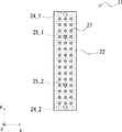
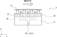
- (Configuration example of precision levitation unit) 7 and 8 are a cross-sectional view and a plan view, respectively, for explaining a configuration example of the precision levitation unit 11.
- the precision levitation units 11a and 11b are collectively referred to as the precision levitation unit 11 as well.
- a configuration example of the precision levitation unit 11 will be described, but the configuration of the semi-precision levitation unit 12 is basically the same as that of the precision levitation unit 11.
- the precision levitation unit 11 includes a pedestal 21 and a porous body 22.
- the porous body 22 is provided on the upper side of the pedestal 21 and functions as a gas ejection part.
- the porous body 22 is connected to the air supply ports 24_1 and 24_2, and the compressed gas is supplied to the porous body 22 through the air supply ports 24_1 and 24_2.
- the air supply ports 24_1 and 24_2 are provided in the lower part of the precision levitation unit 11.
- a plurality of intake holes 27 are formed in the porous body 22.
- the intake hole 27 can be formed by making a through hole in the porous body 22. As shown in FIG. 8, the intake holes 27 are uniformly arranged on the upper surface of the porous body 22 (that is, the surface facing the object to be processed 16).
- the suction hole 27 sucks the gas existing between the workpiece 16 and the precision levitation unit 11 (see FIG. 9).
- the intake hole 27 is connected to the exhaust ports 25_1 and 25_2 via the flow path 26.
- the exhaust ports 25_1 and 25_2 are provided below the precision levitation unit 11.
- An ejector, a vacuum pump, or the like is connected to the exhaust ports 25_1, 25_2, and the exhaust port 25_1, 25_2 is sucked (that is, made into a negative pressure) by using the ejector, the vacuum pump, etc.
- the gas present in the air can be sucked from the intake hole 27.
- FIG. 9 is a cross-sectional view for explaining a state in which the workpiece 16 is being transported using the precision levitation unit 11.
- the gas is ejected upward from the porous body 22, so that when the object 16 is transported onto the precision levitation unit 11, this gas is The workpiece 16 is lifted by colliding with the lower surface of the workpiece 16. Therefore, the precision levitation unit 11 and the workpiece 16 are not in contact with each other.
- the gap between the object to be processed 16 and the precision levitation unit 11, that is, the flying height of the object to be processed 16 is the amount of gas supplied to the air supply ports 24 ⁇ / b> _ ⁇ b> 1 and 24 ⁇ / b> _ ⁇ b> 2. It can be controlled by adjusting the amount of gas.
- the gas existing between the object to be processed 16 and the precision levitation unit 11 (that is, the gas reservoir (see reference numeral 35 in FIG. 12)) is sucked from the intake hole 27, thereby reducing the deflection of the object to be processed 16. can do.
- the workpiece 16 can be flattened.
- the amount of deflection of the workpiece 16 can be controlled by adjusting the balance between the amount of gas supplied to the air supply ports 24_1 and 24_2 and the amount of gas exhausted from the exhaust ports 25_1 and 25_2.
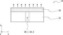
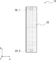
- FIGS. 10 and 11 are a cross-sectional view and a plan view for explaining a configuration example of the rough levitation unit 13, respectively.
- the rough levitation unit 13 includes a pedestal 31 and a porous body 32.
- the porous body 32 is provided on the upper side of the pedestal 31 and functions as a gas ejection part.
- the porous body 32 is connected to the air supply ports 34_1 and 34_2, and the compressed gas is supplied to the porous body 32 through the air supply ports 34_1 and 34_2.
- the air supply ports 34_1 and 34_2 are provided in the lower part of the rough levitation unit 13.
- the compressed gas supplied to the porous body 32 passes through the inside of the porous body 32 and then jets upward from the upper surface of the porous body 32. Thereby, the to-be-processed object 16 floats.
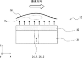
- FIG. 12 is a cross-sectional view for explaining a state in which the workpiece 16 is being transported using the rough levitation unit 13.
- the gas is ejected upward from the porous body 32. Therefore, when the workpiece 16 is conveyed onto the rough levitation unit 13, the gas is covered. The workpiece 16 is lifted by colliding with the lower surface of the workpiece 16. Therefore, the rough levitation unit 13 and the workpiece 16 are not in contact with each other. At this time, a gas reservoir 35 is formed between the workpiece 16 and the rough levitation unit 13. For this reason, in the rough levitation unit 13, the amount of deflection of the workpiece 16 increases.
- the clearance between the object 16 and the rough levitation unit 13, that is, the amount of levitation of the object 16 is the amount of gas supplied to the air supply ports 34_1 and 34_2, in other words, the porous body. It is possible to control by adjusting the amount of gas ejected from 32.
- the amount of gas supplied to the air supply ports 34_1 and 34_2 may not be precisely controlled as compared with the precision levitation unit 11 and the semi-precision levitation unit 12.
- the flatness of the surfaces of the precision levitation units 11a and 11b facing the object to be processed 16 is smaller than the flatness of the surfaces of the rough levitation units 13a to 13f facing the object to be processed 16. It is configured as follows. Further, the flatness of the surfaces of the semi-precise levitation units 12a to 12d facing the object to be processed 16 is larger than the flatness of the surfaces of the precision levitation units 11a and 11b facing the object to be processed 16, and the rough levitation units 13a to 13d. It is configured to be smaller than the flatness of the surface facing the object 16 to be processed 13f. For example, the flatness of the precision levitation unit 11, the semi-precise levitation unit 12, and the rough levitation unit 13 is the flatness of the upper surface of the porous body of each levitation unit.
- the flatness of the precision levitation unit 11 can be determined by using the flying height (the flying height) of the workpiece 16 that floats on the precision levitation unit 11 and the deflection amount of the workpiece 16. Since the method for determining the flatness of the levitation unit is the same as that described in the first embodiment, a duplicate description is omitted.
- FIG. 13 is a block diagram for explaining an example of a piping system (air supply system) of the rough levitation units 13a to 13f.
- the compressed gas supplied from the gas supply source 41 to the piping is branched into two systems and supplied to the filter 42_1 and the filter 42_2, respectively.
- compressed inert gas compressed nitrogen gas or the like
- compressed air can be used as the compressed gas.
- the filter 42_1 removes moisture and impurities contained in the compressed gas supplied from the gas supply source 41.
- the compressed gas after passing through the filter 42_1 is branched into three systems and supplied to speed controllers (speakers) 43_1 to 43_3, respectively.
- Each speed controller 43_1 to 43_3 adjusts the flow rate of the compressed gas flowing through each speed controller 43_1 to 43_3.
- the compressed gas after adjustment is supplied to the air supply ports 34_1 and 34_2 (see FIG. 11) of the rough levitation units 13a to 13c via the flow sensors 44_1 to 44_3.
- the flow sensors 44_1 to 44_3 display the flow rate of the compressed gas supplied to the rough levitation units 13a to 13c.
- the filter 42_2 removes moisture and impurities contained in the compressed gas supplied from the gas supply source 41.
- the compressed gas after passing through the filter 42_2 is branched into three systems and supplied to the speed controllers 43_4 to 43_6, respectively.
- Each speed controller 43_4 to 43_6 adjusts the flow rate of the compressed gas flowing through each speed controller 43_4 to 43_6.
- the compressed gas after adjustment is supplied to the air supply ports 34_1 and 34_2 (see FIG. 11) of the rough levitation units 13d to 13f via the flow sensors 44_4 to 44_6.
- the flow sensors 44_4 to 44_6 display the flow rate of the compressed gas supplied to the rough levitation units 13d to 13f.
- FIG. 14 is a block diagram for explaining an example of the piping system (supply system) of the precision levitation units 11a and 11b and the semi-precision levitation units 12a to 12d.
- the compressed gas supplied from the gas supply source 51 to the pipe is supplied to the filter 52.
- compressed inert gas compressed nitrogen gas or the like
- compressed air can be used as the compressed gas.
- the filter 52 removes moisture and impurities contained in the compressed gas supplied from the gas supply source 51.
- the compressed gas after passing through the filter 52 is branched into eight systems and supplied to the flow controllers 53_1 to 53_8, respectively.
- Each flow controller 53_1 to 53_8 adjusts the flow rate of the compressed gas flowing through each flow controller 53_1 to 53_8.
- the flow controllers 53_1 to 53_8 can be flow sensors with flow rate adjusting throttle valves.
- the compressed gas after adjustment is supplied to each precision levitation unit 11a, 11b and each semi-precision levitation unit 12a-12d.
- the compressed gas whose flow rate is controlled by the flow controller 53_1 is supplied to the air supply port 1 of the precision levitation unit 11a (corresponding to the air supply port 24_1 in FIG. 8, the same applies hereinafter).
- the compressed gas whose flow rate is controlled by the flow controller 53_2 is supplied to the air supply port 2 of the precision levitation unit 11a (corresponding to the air supply port 24_2 in FIG. 8, the same applies hereinafter).
- the compressed gas whose flow rate is controlled by the flow controller 53_3 is supplied to the air supply port 1 of the precision levitation unit 11b.
- the compressed gas whose flow rate is controlled by the flow controller 53_4 is supplied to the air supply port 2 of the precision levitation unit 11b.
- the compressed gas whose flow rate is controlled by the flow controller 53_5 is supplied to the two air supply ports 1 and 2 (corresponding to the air supply ports 24_1 and 24_2 in FIG. 8; the same applies hereinafter) of the semi-precise levitation unit 12a.
- the compressed gas whose flow rate is controlled by the flow controller 53_6 is supplied to the two air supply ports 1 and 2 of the semi-precise levitation unit 12b.
- the compressed gas whose flow rate is controlled by the flow controller 53_7 is supplied to the two air supply ports 1 and 2 of the semi-precise levitation unit 12c.
- the compressed gas whose flow rate is controlled by the flow controller 53_8 is supplied to the two air supply ports 1 and 2 of the semi-precise levitation unit 12d.
- the compressed gas flowing to one semi-precise levitation unit (having two air supply ports) is controlled using one flow controller.
- the precision levitation units 11a and 11b the compressed gas flowing through one precision levitation unit is controlled using two flow controllers. In other words, the compressed gas flowing to one air supply port of the precision levitation unit is controlled using one flow controller. Therefore, the precision levitation units 11a and 11b can control the flow rate of the compressed gas more precisely than the semi-precision levitation units 12a to 12d.
- FIG. 15 is a block diagram for explaining an example of a piping system (exhaust system) of the precision levitation units 11a and 11b and the semi-precision levitation units 12a to 12d.
- the compressed gas supplied from the gas supply source 61 to the pipe is supplied to the regulator 62_1 and the regulator 62_2, respectively.
- compressed air or compressed inert gas such as compressed nitrogen gas
- compressed nitrogen gas can be used as the compressed gas.
- the regulator 62_1 is provided in the system on the precision levitation unit 11a, 11b side, and adjusts the pressure of the compressed gas supplied from the gas supply source 61.
- the compressed gas after passing through the regulator 62_1 is supplied to the speed controller 63_1.
- the speed controller 63_1 adjusts the flow rate of the compressed gas flowing through the speed controller 63_1.
- the compressed gas after adjustment flows to the exhaust line via the ejector 64_1. Thereby, a negative pressure is generated in the pipe to which the ejector 64_1 and the flow controller 65_1 are connected.
- the gas flow in the vicinity of the ejectors 64_1 to 64_4 is indicated by arrows.
- a flow controller 65_1 and a filter 66_1 are provided between the ejector 64_1 and the exhaust port 1 of the precision levitation unit 11a (corresponding to the exhaust port 35_1 in FIG. 8), and the exhaust amount at the exhaust port 1 of the precision levitation unit 11a. Can be adjusted using the flow controller 65_1.
- the regulator 62_2 is provided in the system on the semi-precise levitation units 12a to 12d side, and adjusts the pressure of the compressed gas supplied from the gas supply source 61.
- the configuration on the quasi-precise levitation unit 12a to 12d side is the same as the configuration of the precision levitation unit 11a described above, and a duplicate description is omitted. Although not shown in FIG. 15, the same applies to the piping systems of the semi-precise levitation units 12b to 12d.
- the gas supply amount supplied to the air supply ports of the precision levitation units 11a and 11b and the gas supply amount supplied to the semi-precise levitation units 12a to 12d can be controlled independently.
- the gas suction amount (exhaust amount at the exhaust port) of the precision levitation units 11a and 11b and the gas suction amount (exhaust amount at the exhaust port) of the semi-precision levitation units 12a to 12d can be controlled independently. It is configured.
- FIG. 16 is a cross-sectional view for explaining a state in which the workpiece 16 is being transported using the laser irradiation apparatus 1 according to the present embodiment.
- FIG. 16A when the object 16 passes over the rough levitation units 13a to 13c, the amount of deflection of the object 16 increases.
- FIG. 12 when the workpiece 16 passes over the rough levitation units 13a to 13c, the gas reservoir 35 is placed between the workpiece 16 and the rough levitation units 13a to 13c. Is formed.
- the workpiece 16 is transported, and when the workpiece 16 passes over the semi-precise levitation units 12a and 12b, as shown in FIG. Becomes smaller than the amount of deflection when passing over the rough levitation units 13a to 13c. This is because the gas (that is, the gas reservoir 35 (see FIG. 12)) existing between the workpiece 16 and the semi-precise levitation units 12a and 12b is sucked from the intake hole 27 (see FIG. 9). This is because the deflection of the processing body 16 can be reduced.
- the gas that is, the gas reservoir 35 (see FIG. 12)
- the amount of deflection of the workpiece 16 is determined as follows. Is smaller than the amount of deflection when passing over the semi-precise levitation units 12a and 12b. This is because the gas (that is, the gas reservoir 35 (see FIG. 12)) existing between the workpiece 16 and the precision levitation units 11a and 11b is sucked from the intake hole 27 (see FIG. 9). This is because the deflection of the body 16 can be reduced.
- the semi-precise levitation units 12a and 12b when the workpiece 16 is transported from the rough levitation units 13a to 13c to the precision levitation units 11a and 11b, the amount of deflection of the workpiece 16 changes smoothly. It is because it can be made to do.
- the laser beam 15 is irradiated to the object 16 to be processed.
- the workpiece 16 is further conveyed, and when the workpiece 16 passes over the semi-precise floating units 12c and 12d and the rough floating units 13d to 13f as shown in FIG.
- the amount of deflection of the body 16 is as follows. That is, when the object 16 passes over the rough levitation units 13d to 13f, the amount of deflection of the object 16 increases. As shown in FIG. 12, when the object 16 passes over the rough levitation units 13d to 13f, the gas reservoir 35 is placed between the object 16 and the rough levitation units 13d to 13f. Is formed.
- the deflection amount of the workpiece 16 is such that the workpiece 16 passes over the rough levitation units 13d to 13f. It becomes smaller than the amount of deflection when it is. This is because the gas (that is, the gas reservoir 35 (see FIG. 12)) existing between the workpiece 16 and the semi-precise levitation units 12c and 12d is sucked from the intake hole 27 (see FIG. 9). This is because the deflection of the processing body 16 can be reduced.
- the semi-precise levitation units 12a and 12b are provided between the rough levitation units 13a to 13c and the precision levitation units 11a and 11b. Therefore, when the workpiece 16 is transported from the rough levitation units 13a to 13c to the precision levitation units 11a and 11b, the amount of deflection of the workpiece 16 can be changed smoothly.
- the distance d1 between the position 19a where the deflection of the workpiece 16 is large and the laser irradiation position 15 can be separated, so the laser irradiation apparatus according to the first embodiment.
- the bending of the to-be-processed object 16 in the laser irradiation position 15 can be reduced.
- semi-precise levitation units 12c and 12d are provided between the precision levitation units 11a and 11b and the rough levitation units 13d to 13f. Therefore, when the workpiece 16 is transported from the precision levitation units 11a and 11b to the rough levitation units 13d to 13f, the amount of deflection of the workpiece 16 can be changed smoothly.
- the distance d2 between the position 19b where the workpiece 16 is largely deflected and the laser irradiation position 15 can be separated, so the laser irradiation apparatus according to the first embodiment.
- the bending of the to-be-processed object 16 in the laser irradiation position 15 can be reduced.
- the deflection of the workpiece 16 at the laser irradiation position 15 can be reduced, so that the laser irradiation position 15 deviates from the focal depth (DOF) of the laser beam. Can be suppressed.
- DOE focal depth
- the precision levitation region is formed using two precision levitation units 11a and 11b, and the quasi-precision levitation region is formed using four quasi-precision levitation units 12a to 12d.
- the case where the rough levitation region is formed by using the individual rough levitation units 13a to 13f is shown.
- the number of precision levitation units 11 constituting the precise levitation area, the number of quasi-precise levitation units 12 constituting the quasi-precision levitation area, and the rough levitation areas constituting the rough levitation area can be determined arbitrarily.
- each levitation unit may have a configuration other than that described above.
- the rough levitation unit 13 is not required to have ascending precision as the precision levitation unit 11, so that the area per unit of the rough levitation unit may be larger than the area per unit of the precision levitation unit. Good.
- the structure which does not provide an intake hole in the rough levitation unit was demonstrated above, you may provide an intake hole in a rough levitation unit in this Embodiment.
- the semi-precision levitation unit 12 may be provided on at least one of the upstream side and the downstream side in the transport direction of the workpiece 16 with respect to the precision levitation units 11a and 11b.
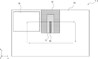
- FIGS. 17 to 21 are plan views for explaining an arrangement example of the precision levitation unit (precision levitation area) 11, the semi-precision levitation unit (semi-precision levitation area) 12, and the rough levitation unit (rough levitation area) 13. is there.
- a precision levitation unit 11, a semi-precise levitation unit 12, and a rough levitation unit 13 are arranged on the stages of the laser irradiation apparatuses 1_1 to 1_5 shown in FIGS. Then, the object to be processed 16 is floated on the stage, and the object to be processed 16 is processed by conveying the object 16 in the direction of the arrow on the stage using a gripping part (not shown).
- the laser irradiation position 15 is arranged from the center of the stage to the end of the stage in the y-axis direction. In other words, the laser irradiation position 15 is approximately the same as the length of the workpiece 16 in the y-axis direction.
- the precision levitation unit 11 is disposed so as to include the laser irradiation position 15.
- the length of the precision levitation unit 11 in the y-axis direction is approximately the same as the length of the laser irradiation position 15 in the y-axis direction.
- the semi-precision levitation unit 12 is disposed on both sides of the precision levitation unit 11 in the x-axis direction.
- the rough levitation unit 13 is disposed at a location other than the location where the precision levitation unit 11 and the semi-precise levitation unit 12 are disposed.
- the object to be processed 16 is staged so as to pass through the laser irradiation position 15 a plurality of times, that is, so that the same portion of the object to be processed 16 is irradiated with the laser light a plurality of times.
- the top may be conveyed.
- the length of the laser irradiation position 15 in the y-axis direction is about half the length of the workpiece 16 in the y-axis direction.
- the laser irradiation position 15 is arranged on the central portion side of the stage, and when the object 16 passes through the laser irradiation position 15, the laser beam is irradiated to a half region in the y-axis direction of the object 16.
- the precision levitation unit 11 is disposed so as to include the laser irradiation position 15.
- the semi-precise levitation unit 12 is disposed so as to surround the precision levitation unit 11 except for the central portion of the stage.
- the rough levitation unit 13 is disposed at a location other than the location where the precision levitation unit 11 and the semi-precise levitation unit 12 are disposed.
- the object to be processed 16 is staged so as to pass through the laser irradiation position 15 a plurality of times, that is, so that the same spot of the object to be processed 16 is irradiated a plurality of times.
- the top may be conveyed.
- the length of the laser irradiation position 15 in the y-axis direction is about half the length of the workpiece 16 in the y-axis direction.
- the laser irradiation position 15 is arranged on the central portion side of the stage, and when the object 16 passes through the laser irradiation position 15, the laser beam is irradiated to a half region in the y-axis direction of the object 16.
- the precision levitation unit 11 is disposed so as to include the laser irradiation position 15.
- the length of the precision levitation unit 11 in the y-axis direction is approximately the same as the length of the laser irradiation position 15 in the y-axis direction.
- the semi-precision levitation unit 12 is disposed on both sides of the precision levitation unit 11 in the x-axis direction.
- the rough levitation unit 13 is disposed at a location other than the location where the precision levitation unit 11 and the semi-precise levitation unit 12 are disposed. In the laser irradiation apparatus 1_3 shown in FIG.
- the object to be processed 16 is staged so as to pass through the laser irradiation position 15 a plurality of times, that is, so that the same spot of the object to be processed 16 is irradiated with the laser light a plurality of times.
- the top may be conveyed.
- the length of the laser irradiation position 15 in the y-axis direction is about half the length of the workpiece 16 in the y-axis direction.
- the laser irradiation position 15 is arranged on the end side of the stage, and when the object 16 passes through the laser irradiation position 15, the laser beam is irradiated to a half region in the y-axis direction of the object 16.
- the precision levitation unit 11 is disposed so as to include the laser irradiation position 15.
- the length of the precision levitation unit 11 in the y-axis direction is longer than the length of the laser irradiation position 15 in the y-axis direction. That is, the precision levitation unit 11 is disposed from the center of the stage to the end of the stage in the y-axis direction.
- the semi-precision levitation unit 12 is disposed on both sides of the precision levitation unit 11 in the x-axis direction.
- the rough levitation unit 13 is disposed at a location other than the location where the precision levitation unit 11 and the semi-precise levitation unit 12 are disposed.
- the object to be processed 16 is staged so as to pass the laser irradiation position 15 a plurality of times, that is, so that the same spot of the object to be processed 16 is irradiated with the laser light a plurality of times.
- the top may be conveyed.
- the length of the laser irradiation position 15 in the y-axis direction is about half the length of the workpiece 16 in the y-axis direction.
- the laser irradiation position 15 is arranged on the end side of the stage, and when the object 16 passes through the laser irradiation position 15, the laser beam is irradiated to a half region in the y-axis direction of the object 16.
- the precision levitation unit 11 is disposed so as to include the laser irradiation position 15.
- the length of the precision levitation unit 11 in the y-axis direction is approximately the same as the length of the laser irradiation position 15 in the y-axis direction.
- the semi-precision levitation unit 12 is disposed on both sides of the precision levitation unit 11 in the x-axis direction.
- the rough levitation unit 13 is disposed at a location other than the location where the precision levitation unit 11 and the semi-precise levitation unit 12 are disposed. In the laser irradiation apparatus 1_5 shown in FIG.
- the object to be processed 16 is staged so as to pass through the laser irradiation position 15 a plurality of times, that is, so that the same spot of the object to be processed 16 is irradiated with the laser light a plurality of times.
- the top may be conveyed.
- the relatively expensive precision levitation unit 11 and the semi-precise levitation unit 12 are arranged only near the laser beam irradiation position 15, and the rough area that can be constructed at low cost in other areas.
- a levitation unit 13 is arranged. That is, since most of the levitation unit is constituted by the inexpensive rough levitation unit 13, the cost of the laser irradiation apparatus can be reduced. Moreover, since the area
- FIG. 22 is a plan view for explaining another configuration example of the semi-precision levitation unit.
- the rough levitation unit 13, the semi-precise levitation unit 70, and the precision levitation unit 11 are arranged to be aligned in the transport direction.
- a porous body is formed on the upper surfaces of the rough levitation unit 13, the semi-precise levitation unit 70, and the precision levitation unit 11, that is, on the side facing the object 16.
- the to-be-processed object 16 floats.
- the semi-precision unit 70 and the precision levitation unit 11 are provided with a plurality of intake holes 71 and 27 for sucking gas existing between the object 16 and the object to be processed 16.
- the plurality of intake holes 71 are arranged to be denser on the precision levitation unit 11 side than on the rough levitation unit 13 side.
- the intake holes 27 are densely arranged in the same manner as the intake holes 71 on the precision levitation unit 11 side of the semi-precise levitation unit 70.
- the arrangement of the intake holes 71 of the semi-precise levitation unit 70 is arranged so that the density of the intake holes 71 gradually increases from the rough levitation unit 13 side to the precision levitation unit 11 side.
- the amount of deflection of the object 16 can be changed more smoothly.
- FIG. 23 is a cross-sectional view for explaining another configuration example of the precision levitation unit.
- the precision levitation unit shown in FIG. 23 is configured using lower units 81a and 81b and upper units 81c and 81d.
- the lower units 81a and 81b and the upper units 81c and 81d are also collectively referred to as precision levitation units 81a to 81d.
- the lower units 81a and 81b correspond to the precision levitation units 11a and 11b described above, and gas is ejected upward from the porous body disposed on the upper surfaces of the lower units 81a and 81b, so that the workpiece 16 is processed. To surface. Further, the gas existing between the object to be processed 16 and the lower units 81a and 81b is sucked using a plurality of intake holes formed on the upper surfaces of the lower units 81a and 81b, so that the bending of the object to be processed 16 occurs. Reduce.
- the upper units 81c and 81d are arranged above the lower units 81a and 81b. In other words, the upper units 81c and 81d are arranged at positions facing the lower units 81a and 81b with the workpiece 16 interposed therebetween.
- the upper units 81 c and 81 d spray gas onto the upper surface of the workpiece 16 when the workpiece 16 is transported. Thereby, the deflection of the workpiece 16 can be further reduced.
- a gap is formed between the upper unit 81c and the upper unit 81d, and the seal gas 85 is supplied to the surface of the workpiece 16 from this gap.
- the seal gas 85 is an inert gas such as nitrogen
- the gas blown from the upper units 81c and 81d is also an inert gas such as nitrogen. Therefore, the surface of the irradiation position of the laser beam 15 on the workpiece 16 can be locally sealed with an inert gas such as nitrogen gas.
- a laser displacement meter is provided on the upper side of the upper units 81c and 81d so that the laser for measuring the laser displacement meter passes through the gap between the upper unit 81c and the upper unit 81d.
- the displacement (deflection amount) in the z-axis direction at the irradiation position of the laser beam 15 can be measured in real time.
- the gas ejection amount and the suction amount of the precision levitation units 81a to 81d and the semi-precise levitation unit 12 may be feedback-controlled.
- upper units 86a and 86b as shown in FIG. 24 may be provided instead of the upper units 81c and 81d shown in FIG.
- the upper units 86a and 86b shown in FIG. 24 are disposed above the lower units 81a and 81b.
- the upper units 86a and 86b are arranged at positions facing the lower units 81a and 81b with the workpiece 16 interposed therebetween.
- the upper units 86a and 86b shown in FIG. 24 have a configuration in which no gas is blown onto the upper surface of the object 16 when the object 16 is transported.
- the precision levitation unit shown in FIG. 24 conveys the workpiece 16 using the lower units 81a and 81b.
- a gap is formed between the upper unit 86a and the upper unit 86b, and the seal gas 85 is supplied to the surface of the workpiece 16 from this gap.
- the seal gas 85 is an inert gas such as nitrogen. Therefore, the surface of the irradiation position of the laser beam 15 on the workpiece 16 can be locally sealed with an inert gas such as nitrogen gas.
- a plate-like member 87a is provided on the upstream side of the upper unit 86a, and a plate-like member 87b is provided on the downstream side of the upper unit 86b.
- the sealing effect by the seal gas 85 can be enhanced.
- the upper units 86a and 86b and the plate-like members 87a and 87b can be configured using aluminum plates.
- FIG. 25 is a cross-sectional view for explaining another configuration example of each levitation unit provided in the laser irradiation apparatus 2.
- the precision levitation unit is configured using lower units 91a and 91b and upper units 91c and 91d.
- the lower units 91a and 91b and the upper units 91c and 91d are also collectively referred to as precision levitation units 91a to 91d.
- the lower units 91a and 91b jet the gas upward from the porous body disposed on the upper surfaces of the lower units 91a and 91b to float the object 16 to be processed.
- the lower units 91a and 91b do not include an intake hole (see FIG. 9) for sucking the gas existing between the workpiece 16 and the lower units 91a and 91b.
- the upper units 91c and 91d are arranged above the lower units 91a and 91b. In other words, the upper units 91c and 91d are arranged at positions facing the lower units 91a and 91b with the workpiece 16 interposed therebetween.
- the upper units 91 c and 91 d spray gas onto the upper surface of the object to be processed 16 when the object to be processed 16 is transported. As described above, the object 16 is sandwiched between the lower units 91a and 91b and the upper units 91c and 91d, and the gas is blown from the vertical direction of the object 16 so that the object 16 can be transported when the object 16 is transported. Deflection can be reduced.
- the gas blown from the upper units 91c and 91d is an inert gas such as nitrogen. Therefore, the surface of the irradiation position of the laser beam 15 on the workpiece 16 can be locally sealed with an inert gas such as nitrogen gas.
- an inert gas such as nitrogen gas.
- sealing gas in the laser irradiation apparatus 2 shown in FIG. 25, a gap is formed between the upper unit 91c and the upper unit 91d. Therefore, sealing gas (inert gas such as nitrogen) may be supplied to the surface of the object 16 from this gap.
- the semi-precise levitation units 92a and 92b jet the gas from above the semi-precise levitation units 92a and 92b, and the object 16 is levitated.
- the semi-precision levitation units 92a and 92b have intake holes (see FIG. 9) for sucking the gas existing between the workpiece 16 and the quasi-precision levitation units 92a and 92b. Not prepared.
- the rough levitation units 93a and 93b jet the gas from above the rough levitation units 93a and 93b to float the object 16 to be processed.
- the rough levitation units 93a and 93b have the same configuration as that of the laser irradiation apparatus 1 shown in FIGS.
- each floating unit 91a, 91b, 92a, 92b, 93a, 93b arranged at the lower part of the workpiece 16 is used by a unit that ejects gas only in the upward direction. It is composed.
- upper units 91 c and 91 d are provided in the precision levitation region, and gas is blown onto the upper surface of the object to be processed 16 when the object to be processed 16 is transported.
- the semi-precise levitation units 92a and 92b are configured to be able to control the gas ejection amount more precisely than the rough levitation units 93a and 93b.
- the semi-precise levitation unit 92a is configured so that the amount of deflection of the workpiece 16 changes smoothly when the workpiece 16 is transported from the rough levitation unit 93a to the precision levitation units 91a to 91d. Can be transported.
- the semi-precise levitation unit 92b is configured so that the amount of deflection of the workpiece 16 changes smoothly when the workpiece 16 is transported from the precision levitation units 91a to 91d to the rough levitation unit 93b. Can be transported.
- a laser displacement meter is provided above the upper units 91c and 91d, and a laser for measuring the laser displacement meter passes through a gap between the upper unit 91c and the upper unit 91d.
- the displacement (deflection amount) in the z-axis direction at the irradiation position of the laser beam 15 on the object 16 can be measured in real time.
- the gas ejection amount of the precision levitation units 91a to 91d and the semi-precision levitation units 92a and 92b may be feedback-controlled.
- the amorphous film formed over the substrate can be irradiated with laser light to crystallize the amorphous film.
- the semiconductor device is a semiconductor device including a TFT (Thin Film Transistor).
- the amorphous silicon film can be irradiated with laser light to be crystallized to form a polysilicon film.
- FIG. 26 is a cross-sectional view for explaining an example of a method for manufacturing a semiconductor device.
- the laser irradiation apparatus according to the present embodiment described above is suitable for manufacturing a TFT array substrate.
- a method for manufacturing a semiconductor device having a TFT will be described.
- the gate electrode 202 is formed on the glass substrate 201.
- a metal thin film containing aluminum or the like can be used for the gate electrode 202.
- a gate insulating film 203 is formed on the gate electrode 202.
- the gate insulating film 203 is formed so as to cover the gate electrode 202.
- an amorphous silicon film 204 is formed on the gate insulating film 203 as shown in Step C of FIG.
- the amorphous silicon film 204 is disposed so as to overlap the gate electrode 202 with the gate insulating film 203 interposed therebetween.
- the gate insulating film 203 is a silicon nitride film (SiN x ), a silicon oxide film (SiO 2 film), or a laminated film thereof. Specifically, the gate insulating film 203 and the amorphous silicon film 204 are continuously formed by a CVD (Chemical Vapor Deposition) method.
- CVD Chemical Vapor Deposition
- Step D of FIG. 26 the amorphous silicon film 204 is crystallized by irradiating the amorphous silicon film 204 with laser light using the laser irradiation apparatus described above, thereby forming a polysilicon film 205. .
- a polysilicon film 205 in which silicon is crystallized is formed on the gate insulating film 203.
- the deflection of the substrate 201 can be reduced when the substrate 201 (object to be processed) is transported, and the amorphous silicon film 204 is irradiated. It can suppress that it remove
- DOE focal depth
- an interlayer insulating film 206, a source electrode 207a, and a drain electrode 207b are formed on the polysilicon film 205.
- the interlayer insulating film 206, the source electrode 207a, and the drain electrode 207b can be formed using a general photolithography method or a film formation method.
- a semiconductor device including a TFT can be manufactured.
- description is abbreviate
- FIG. 27 is a cross-sectional view for explaining the outline of the organic EL display, and shows a simplified pixel circuit of the organic EL display.
- An organic EL display 300 shown in FIG. 27 is an active matrix display device in which a TFT is disposed in each pixel PX.
- the organic EL display 300 includes a substrate 310, a TFT layer 311, an organic layer 312, a color filter layer 313, and a sealing substrate 314.
- FIG. 27 shows a top emission type organic EL display in which the sealing substrate 314 side is the viewing side.
- the following description shows one configuration example of the organic EL display, and the present embodiment is not limited to the configuration described below.
- the semiconductor device according to the present embodiment may be used in a bottom emission type organic EL display.
- the substrate 310 is a glass substrate or a metal substrate.
- a TFT layer 311 is provided on the substrate 310.
- the TFT layer 311 includes a TFT 311a disposed in each pixel PX. Further, the TFT layer 311 includes a wiring connected to the TFT 311a.
- the TFT 311a, wiring, and the like constitute a pixel circuit. Note that the TFT layer 311 corresponds to the TFT described with reference to FIG. 26, and includes a gate electrode 202, a gate insulating film 203, a polysilicon film 205, an interlayer insulating film 206, a source electrode 207a, and a drain electrode 207b.
- the organic layer 312 has an organic EL light emitting element 312a arranged for each pixel PX.
- the organic EL light emitting element 312a has, for example, a stacked structure in which an anode, a hole injection layer, a hole transport layer, a light emitting layer, an electron transport layer, an electron injection layer, and a cathode are stacked.
- the anode is a metal electrode
- the cathode is a transparent conductive film such as ITO (Indium Tin Oxide).
- the organic layer 312 is provided with a partition 312b for separating the organic EL light emitting element 312a between the pixels PX.
- a color filter layer 313 is provided on the organic layer 312.
- the color filter layer 313 is provided with a color filter 313a for performing color display. That is, each pixel PX is provided with a resin layer colored in R (red), G (green), or B (blue) as the color filter 313a.
- R red
- G green
- B blue
- the color filter layer 313 may be omitted in the case of a three-color system in which the organic layer 312 is provided with organic EL light-emitting elements that emit RGB colors.
- the sealing substrate 314 is a transparent substrate such as a glass substrate, and is provided to prevent deterioration of the organic EL light emitting element of the organic layer 312.
- the current flowing through the organic EL light emitting element 312a of the organic layer 312 varies depending on the display signal supplied to the pixel circuit. Therefore, the amount of light emitted from each pixel PX can be controlled by supplying a display signal corresponding to the display image to each pixel PX. Thereby, a desired image can be displayed.
- an organic EL display has been described as an example of a device using a semiconductor device including a TFT.
- the semiconductor device including a TFT may be a liquid crystal display, for example.
- the laser irradiation apparatus concerning this Embodiment was applied to the laser annealing apparatus was demonstrated above.
- the laser irradiation apparatus according to this embodiment can be applied to apparatuses other than the laser annealing apparatus.
Landscapes
- Physics & Mathematics (AREA)
- Optics & Photonics (AREA)
- Engineering & Computer Science (AREA)
- Mechanical Engineering (AREA)
- Plasma & Fusion (AREA)
- Fluid Mechanics (AREA)
- Container, Conveyance, Adherence, Positioning, Of Wafer (AREA)
- Laser Beam Processing (AREA)
- Recrystallisation Techniques (AREA)
- Electromagnetism (AREA)
- Cleaning Or Drying Semiconductors (AREA)
- Toxicology (AREA)
- Health & Medical Sciences (AREA)
- Robotics (AREA)
Abstract
一実施の形態にかかるレーザ照射装置(1)は、被処理体(16)を浮上ユニット(10)を用いて浮上させて搬送しながら被処理体(16)にレーザ光(15)を照射する。浮上ユニット(10)は、精密浮上領域(11a、11b)、及びラフ浮上領域(13a~13j)を備える。精密浮上領域(11a、11b)は、ガスの噴出および吸引を用いて被処理体(16)を浮上させるように構成されており、ラフ浮上領域は、ガスの吸引を用いず、ガスの噴出を用いて被処理体(16)を浮上させるように構成されている。
Description
本発明はレーザ照射装置、レーザ照射方法、及び半導体装置の製造方法に関し、例えば被処理体を浮上させて搬送する浮上ユニットを備えるレーザ照射装置、レーザ照射方法、及び半導体装置の製造方法に関する。
シリコン基板やガラス基板などに形成された非晶質膜にレーザ光を照射して非晶質膜を結晶化させるレーザアニール装置が知られている。特許文献1には、ガス浮上装置を用いて基板を浮上させて搬送しながらレーザ光を照射するレーザアニール装置が開示されている。
特許文献1に開示されているレーザアニール装置のように、基板にガスを吹き付けて被処理体を浮上させて搬送するレーザアニール装置では、被処理体に吹き付けられるガスが不均一になると搬送時に被処理体のたわみ量が大きくなり、被処理体におけるレーザ光の焦点深度(DOF:Depth of Focus)から外れてしまうという問題がある。
その他の課題と新規な特徴は、本明細書の記述および添付図面から明らかになるであろう。
一実施の形態にかかるレーザ照射装置は、第1の領域と第2の領域とを備える浮上ユニットを有する。第1の領域は、ガスの噴出および吸引を用いて被処理体を浮上させるように構成されており、第2の領域は、ガスの吸引を用いず、ガスの噴出を用いて被処理体を浮上させるように構成されている。
一実施の形態にかかるレーザ照射方法は、第1の領域と第2の領域とを備える浮上ユニットを用いて被処理体を搬送する際、第1の領域においてガスの噴出および吸引を用いて被処理体を浮上させて搬送し、第2の領域においてガスの吸引を用いず、ガスの噴出を用いて被処理体を浮上させて搬送する。
一実施の形態にかかる半導体装置の製造方法は、(a)基板上に非晶質膜を形成するステップと、(b)前記非晶質膜にレーザ光を照射して前記非晶質膜を結晶化させるステップと、を含む半導体装置の製造方法であって、(b)のステップにおいて、第1の領域と第2の領域とを備える浮上ユニットを用いて被処理体を搬送する際、第1の領域においてガスの噴出および吸引を用いて被処理体を浮上させて搬送し、第2の領域においてガスの吸引を用いず、ガスの噴出を用いて被処理体を浮上させて搬送する。
前記一実施の形態によれば、搬送時に被処理体のたわみを低減させることが可能なレーザ照射装置、レーザ照射方法、及び半導体装置の製造方法を提供することができる。
<実施の形態1>
以下、図面を用いて実施の形態1にかかるレーザ照射装置について説明する。図1は、実施の形態1にかかるレーザ照射装置を説明するための平面図である。図2は、図1に示すレーザ照射装置の切断線II-IIにおける断面図である。
(レーザ照射装置の構成)
図1、図2に示すように、レーザ照射装置1は、浮上ユニット10を備える。浮上ユニット10は、被処理体16を浮上させながら搬送する。具体的には、レーザ照射装置1は、浮上ユニット10を用いて被処理体16を浮上させながら、把持部18(図1参照)を用いて被処理体16を把持して搬送方向(x軸方向)に被処理体16を搬送する。被処理体16が搬送される際、浮上ユニット10は被処理体16の上側に配置されている他の機構(不図示)に被処理体16が接触しないように浮上量を調整している。
図1、図2に示すように、レーザ照射装置1は、浮上ユニット10を備える。浮上ユニット10は、被処理体16を浮上させながら搬送する。具体的には、レーザ照射装置1は、浮上ユニット10を用いて被処理体16を浮上させながら、把持部18(図1参照)を用いて被処理体16を把持して搬送方向(x軸方向)に被処理体16を搬送する。被処理体16が搬送される際、浮上ユニット10は被処理体16の上側に配置されている他の機構(不図示)に被処理体16が接触しないように浮上量を調整している。
把持部18には、例えば吸盤型の真空吸着機構や多孔質体を備える真空吸着機構を用いることができる。把持部18は、排気ポート(不図示)と接続されており、排気ポートはエジェクタや真空ポンプなどと接続されている。よって、吸気ポートには、ガスを吸引するための負圧が作用する。これにより把持部18の真空吸着機構が被処理体16に吸着する。把持部18は、被処理体16を把持しながら、把持部18の駆動機構によって搬送される。これにより、被処理体16が搬送される。なお、被処理体16の搬送速度は、把持部18の駆動機構の搬送速度を調整することで制御することができる。例えば、被処理体16は、浮上ユニット10の上を浮上した状態で等速に搬送される。よって、被処理体16はレーザ光の照射位置を一定の速度で通過する。
被処理体16にはレーザ光15(以下、レーザ光の照射位置も符号15で示す)が照射される。例えば、レーザ照射装置はレーザアニール装置であり、この場合はレーザ発生装置14にエキシマレーザ等を用いることができる。レーザ発生装置14から供給されたレーザ光は、光学系(不図示)においてライン状となり、被処理体16にはライン状、具体的には焦点がy軸方向に伸びるレーザ光15(ラインビーム)が照射される。また、被処理体は、例えば基板上に形成された非晶質膜であり、この非晶質膜にレーザ光15を照射してアニール処理することで、非晶質膜を結晶化させることができる。
図1、図2に示すように、浮上ユニット10は、精密浮上ユニット11a、11b、及びラフ浮上ユニット13a~13jを用いて構成されている。なお、以下では、精密浮上ユニット11a、11bを用いて構成されている領域を精密浮上領域11a、11bと、また、ラフ浮上ユニット13a~13jを用いて構成されている領域をラフ浮上領域13a~13jとも記載する。
精密浮上ユニット11a、11bは、レーザ光の照射位置15を含む領域(精密浮上領域)に配置されている。また、ラフ浮上ユニット13a~13eは、精密浮上ユニット11a、11bに対して、被処理体16の搬送方向上流側(x軸方向マイナス側)に配置されている。また、ラフ浮上ユニット13f~13jは、精密浮上ユニット11a、11bに対して、被処理体16の搬送方向下流側(x軸方向プラス側)に配置されている。図1、図2に示すように、精密浮上ユニット11a、11b、及びラフ浮上ユニット13a~13jの各々は、例えばy軸方向に伸びる矩形状のユニットであり、これらの浮上ユニットが搬送方向(x軸方向)に並ぶように配置されている。被処理体16は、ラフ浮上ユニット13a~13e、精密浮上ユニット11a、11b、ラフ浮上ユニット13f~13jの順に通過して搬送される。なお、各々の浮上ユニットの形状は矩形状に限定されることはない。例えば、各々の浮上ユニットの形状は正方形であってもよい。
換言すると、精密浮上ユニット11a、11bは、平面視した際にレーザ光15の焦点(レーザ光の照射位置15に対応。以下、同様。)と精密浮上領域11a、11bとが重畳するように配置されている。また、ラフ浮上ユニット13a~13jは、レーザ光15の焦点とラフ浮上領域13a~13jとが重畳しないように配置されている。ここで、平面視した場合とは、図1に示すように、浮上ユニット10をz軸方向側からみた場合を意味する。
精密浮上ユニット11a、11bは、被処理体16を精密に浮上させて搬送するユニットであり、搬送時の被処理体16のたわみ量を小さくしながら搬送することができるように構成されている。精密浮上ユニット11a、111bは、例えば、被処理体16を浮上させるためのガスの噴出量を精密に制御している。例えば、精密浮上領域(精密浮上ユニット)11a、11bは、ガスの噴出および吸引を用いて被処理体16を浮上させるように構成されている。なお、精密浮上ユニット11a、11bの詳細な構成については、図7~図9を用いて具体的に説明している。
ラフ浮上ユニット13a~13jは、被処理体16を浮上させて搬送するユニットであり、搬送時に被処理体16がラフ浮上ユニット13a~13jに接触しなければよいため、被処理体16を浮上させるためのガスの噴出量は、精密浮上ユニット11a、11bほど精密に制御していない。このため、ラフ浮上ユニット13a~13jを通過する際の被処理体16のたわみ量は、精密浮上ユニット11a、11bを通過する際の被処理体16のたわみ量よりも大きい。例えば、ラフ浮上領域(ラフ浮上ユニット)13a~13jは、ガスの吸引を用いず、ガスの噴出を用いて被処理体16を浮上させるように構成されている。なお、ラフ浮上ユニット13a~13jの詳細な構成については、図10~図12を用いて具体的に説明している。
ここで、精密浮上ユニット11a、11bは、搬送時の被処理体16のたわみ量を小さくしながら搬送することができるように構成されている。よって、精密浮上ユニット11a、11bは、単にガスを噴出して被処理体16を搬送する構成のラフ浮上ユニット13a~13jと比べて精密な構造を備えるため、高価なユニットである。このため、実施の形態1にかかるレーザ照射装置10では、レーザ光の照射位置15を含む領域にのみ精密浮上ユニット11a、11bを配置し、これ以外の領域には精密浮上ユニットと比べて安価に構成できるラフ浮上ユニット13a~13jを配置している。
また、本実施の形態では、精密浮上ユニット11a、11bの被処理体16と対向する面の平面度は、ラフ浮上ユニット13a~13jの被処理体16と対向する面の平面度よりも小さくなるように構成している。一例を挙げると、精密浮上ユニット11a、11bの平面度は20μm以下であり、ラフ浮上ユニット13a~13jの平面度は75μm以下である。なお、以下では、精密浮上ユニット11a、11bを精密浮上ユニット11と記載し、ラフ浮上ユニット13a~13jをラフ浮上ユニット13と記載する場合もある。
例えば、精密浮上ユニット11の平面度は、精密浮上ユニット11の上を浮上する被処理体16の浮上量(浮上高さ)と被処理体16のたわみ量とを用いて定めることができる。被処理体16のたわみは、被処理体16の浮上量と浮上ユニットの表面の平面度が影響を与えていると考えられる。ここで、被処理体16の浮上量は、被処理体16と浮上ユニットとの間に存在するガスにより作用する圧力が影響を与えていると考えられる。
図3は、浮上ユニットの平面度と被処理体のたわみとの関係を説明するための断面図である。図3に示すように、浮上ユニットの平面度は、浮上ユニットの最も低い部分である基準点S1と浮上ユニットの最も高い部分であるT1との距離で定義することができる。また、被処理体16のたわみは、被処理体16の最も低い部分である基準点S2と被処理体16の最も高い部分であるT2との距離で定義することができる。
ラフ浮上ユニット13では被処理体16の端部の浮上量が最も低くなるため、ラフ浮上ユニット13との衝突を避けるために、ラフ浮上ユニット13の表面の平面度をある程度小さくする必要がある。図3に示すように、被処理体16は浮上ユニットに衝突しないように浮上するが、被処理体16の浮上量は浮上ユニットの表面をゼロ点とした高さになるため、ラフ浮上ユニット側も表面の平面度を小さくしなければ両者は衝突する恐れがある。つまり、図3に示すように、ラフ浮上ユニットの表面の平面度をある程度小さくして、浮上ユニットの最も高い部分T1が被処理体16の最も低い部分S2と衝突しないようにする必要がある。
精密浮上ユニット11では、ラフ浮上ユニット13と比較すると被処理体16の浮上量を小さくしており、また被処理体16の端部の浮上量が最も低くなるため、浮上ユニットとの衝突を避ける工夫が必要となる。例えば、図4Bのラフ浮上ユニット13eと精密浮上ユニット11aとの境界付近のように、被処理体16のたわみや浮上量が急激に変化すると、レーザ照射部への影響が大きくなる。よって、精密浮上ユニット11でも平面度が充分に確保できていない場合は被処理体16のたわみの変動によりレーザ照射に悪影響を及ぼす恐れがある。このような理由から、精密浮上ユニット11の平面度を小さくする必要がある。
また、精密浮上ユニット11の平面度は、ラフ浮上ユニット13の平面度よりも小さくする必要があるため、精密浮上ユニット11の平面度を維持するためには、各々の精密浮上ユニットの上面の面積を、ラフ浮上ユニットの上面の面積よりも小さくすることが好ましい。一方、ラフ浮上ユニット13は、被処理体16を浮上ユニットに衝突させることなく浮上・搬送させるため、精密浮上ユニット11と比べて上面の面積を大きくすることができる。
なお、上記では、各々の浮上ユニットの上面の面積の一例について説明したが、精密浮上ユニット11a、11bおよびラフ浮上ユニット13a~13jの上面の面積は同一としてもよい。本実施の形態(図1参照)では、説明を簡略化するために各々の浮上ユニットの上面の面積を同一としている。
図4は、レーザ照射装置1を用いて被処理体16を搬送している状態を説明するための断面図である。図4Aに示すように、被処理体16がラフ浮上ユニット13a~13eの上を通過している際は、被処理体16のたわみ量は大きくなる。これは、ラフ浮上ユニット13a~13eを用いて被処理体16を搬送する場合は、被処理体16がラフ浮上ユニット13a~13eと接触しなければよく、このため、ガスの噴出量を精密に制御していないためである。
その後、被処理体16が搬送され、図4Bに示すように、被処理体16が精密浮上ユニット11a、11bの上を通過している際は、被処理体16のたわみ量は、被処理体16がラフ浮上ユニット13a~13eの上を通過している際のたわみ量よりも小さくなる。よって、たわみの少ない被処理体16にレーザ光15を照射することができる。
その後、被処理体16が搬送されて、図4Cに示すように、被処理体16がラフ浮上ユニット13f~13jの上を通過している際は、被処理体16のたわみ量は大きくなる。これは、ラフ浮上ユニット13f~13jを用いて被処理体16を搬送する場合は、被処理体16がラフ浮上ユニット13f~13jと接触しなければよく、このため、ガスの噴出量を精密に制御していないためである。
このように、実施の形態1にかかるレーザ照射装置1では、レーザ光の照射位置15を含む領域に精密浮上ユニット11a、11bを配置し、被処理体16のたわみ量が小さくなるようにしている。よって、被処理体16に照射されるレーザ光の焦点深度(DOF)から外れてしまうことを抑制することができる。
また、実施の形態1にかかるレーザ照射装置1では、レーザ光の照射位置15を含む領域にのみ精密浮上ユニット11a、11bを配置し、これ以外の領域には精密浮上ユニットと比較して安価に構成できるラフ浮上ユニット13a~13jを配置している。よって、レーザ照射装置1のコストを低減させることができる。また、精密な制御が必要な領域を精密浮上ユニット11a、11bが配置されている領域に限定することができるので、レーザ照射装置1の制御を簡便にすることができる。
<実施の形態2>
次に、実施の形態2にかかるレーザ照射装置について説明する。図5は、実施の形態2にかかるレーザ照射装置を説明するための平面図である。図6は、図5に示すレーザ照射装置の切断線V-Vにおける断面図である。レーザ照射装置1は、被処理体16を浮上ユニット10を用いて浮上させて搬送しながら被処理体16にレーザ光15を照射する装置である。
次に、実施の形態2にかかるレーザ照射装置について説明する。図5は、実施の形態2にかかるレーザ照射装置を説明するための平面図である。図6は、図5に示すレーザ照射装置の切断線V-Vにおける断面図である。レーザ照射装置1は、被処理体16を浮上ユニット10を用いて浮上させて搬送しながら被処理体16にレーザ光15を照射する装置である。
(レーザ照射装置の構成)
図5、図6に示すように、レーザ照射装置1は、浮上ユニット10を備える。浮上ユニット10は、被処理体16を浮上させながら搬送する。具体的には、レーザ照射装置1は、浮上ユニット10を用いて被処理体16を浮上させながら、把持部18(図5参照)を用いて被処理体16を把持して搬送方向(x軸方向)に被処理体16を搬送する。被処理体16が搬送される際、浮上ユニット10は被処理体16の上側に配置されている他の機構(不図示)に被処理体16が接触しないように浮上量を調整している。
図5、図6に示すように、レーザ照射装置1は、浮上ユニット10を備える。浮上ユニット10は、被処理体16を浮上させながら搬送する。具体的には、レーザ照射装置1は、浮上ユニット10を用いて被処理体16を浮上させながら、把持部18(図5参照)を用いて被処理体16を把持して搬送方向(x軸方向)に被処理体16を搬送する。被処理体16が搬送される際、浮上ユニット10は被処理体16の上側に配置されている他の機構(不図示)に被処理体16が接触しないように浮上量を調整している。
把持部18には、例えば吸盤型の真空吸着機構や多孔質体を備える真空吸着機構を用いることができる。把持部18は、排気ポート(不図示)と接続されており、排気ポートはエジェクタや真空ポンプなどと接続されている。よって、吸気ポートには、ガスを吸引するための負圧が作用する。これにより把持部18の真空吸着機構が被処理体16に吸着する。把持部18は、被処理体16を把持しながら、把持部18の駆動機構によって搬送される。これにより、被処理体16が搬送される。なお、被処理体16の搬送速度は、把持部18の駆動機構の搬送速度を調整することで制御することができる。例えば、被処理体16は、浮上ユニット10の上を浮上した状態で等速に搬送される。よって、被処理体16はレーザ光の照射位置を一定の速度で通過する。
被処理体16にはレーザ光15(以下、レーザ光の照射位置も符号15で示す)が照射される。例えば、レーザ照射装置はレーザアニール装置であり、この場合はレーザ発生装置14にエキシマレーザ等を用いることができる。レーザ発生装置14から供給されたレーザ光は、光学系(不図示)においてライン状となり、被処理体16にはライン状、具体的には焦点がy軸方向に伸びるレーザ光15(ラインビーム)が照射される。また、被処理体は、例えば基板上に形成された非晶質膜であり、この非晶質膜にレーザ光15を照射してアニール処理することで、非晶質膜を結晶化させることができる。
図5、図6に示すように、浮上ユニット10は、精密浮上ユニット11a、11b、準精密浮上ユニット12a~12d、及びラフ浮上ユニット13a~13fを用いて構成されている。なお、以下では、精密浮上ユニット11a、11bを用いて構成されている領域を精密浮上領域11a、11bと、準精密浮上ユニット12a~12dを用いて構成されている領域を準精密浮上領域12a~12dと、また、ラフ浮上ユニット13a~13fを用いて構成されている領域をラフ浮上領域13a~13fとも記載する。
精密浮上ユニット11a、11bは、レーザ光の照射位置15を含む領域(精密浮上領域)に配置されている。準精密浮上ユニット12a、12bは、精密浮上ユニット11a、11bと隣接するように配置されており、精密浮上ユニット11a、11bに対して、被処理体16の搬送方向上流側(x軸方向マイナス側)に配置されている。ラフ浮上ユニット13a~13cは、準精密浮上ユニット12a、12bと隣接するように配置されており、準精密浮上ユニット12a、12bに対して、被処理体16の搬送方向上流側(x軸方向マイナス側)に配置されている。
また、準精密浮上ユニット12c、12dは、精密浮上ユニット11a、11bと隣接するように配置されており、精密浮上ユニット11a、11bに対して、被処理体16の搬送方向下流側(x軸方向プラス側)に配置されている。ラフ浮上ユニット13d~13fは、準精密浮上ユニット12c、12dと隣接するように配置されており、準精密浮上ユニット12c、12dに対して、被処理体16の搬送方向下流側(x軸方向プラス側)に配置されている。
換言すると、精密浮上ユニット11a、11bは、平面視した際にレーザ光15の焦点と精密浮上領域11a、11bとが重畳するように配置されている。また、ラフ浮上ユニット13a~13fは、レーザ光15の焦点とラフ浮上領域13a~13fとが重畳しないように配置されている。ここで、平面視した場合とは、図5に示すように、浮上ユニット10をz軸方向側からみた場合を意味する。準精密浮上ユニット12a、12bは、精密浮上領域11a、11bとラフ浮上領域13a~13cとの間に配置されている。また、準精密浮上ユニット12c、12dは、精密浮上領域11a、11bとラフ浮上領域13d~13fとの間に配置されている。
図5、図6に示すように、精密浮上ユニット11a、11b、準精密浮上ユニット12a~12d、及びラフ浮上ユニット13a~13fの各々は、例えばy軸方向に伸びる矩形状のユニットであり、これらの浮上ユニットが搬送方向(x軸方向)に沿って並ぶように配置されている。被処理体16は、ラフ浮上ユニット13a~13c、準精密浮上ユニット12a、12b、精密浮上ユニット11a、11b、準精密浮上ユニット12c、12d、ラフ浮上ユニット13d~13fの順に通過して搬送される。なお、各々の浮上ユニットの形状は矩形状に限定されることはない。例えば、各々の浮上ユニットの形状は正方形であってもよい。
精密浮上ユニット11a、11bは、被処理体16を精密に浮上させて搬送するユニットであり、搬送時の被処理体16のたわみ量を小さくしながら搬送することができるように構成されている。精密浮上ユニット11a、11bは、例えば、被処理体16を浮上させるためのガスの噴出量を精密に制御している。例えば、精密浮上領域(精密浮上ユニット)11a、11bは、ガスの噴出および吸引を用いて被処理体16を浮上させるように構成されている。
ラフ浮上ユニット13a~13fは、被処理体16を浮上させて搬送するユニットであり、搬送時に被処理体16がラフ浮上ユニット13a~13fと接触しなければよいため、被処理体16を浮上させるためのガスの噴出量は、精密浮上ユニット11a、11bほど精密に制御していない。このため、ラフ浮上ユニット13a~13fを通過する際の被処理体16のたわみ量は、精密浮上ユニット11a、11bを通過する際の被処理体16のたわみ量よりも大きい。例えば、ラフ浮上領域(ラフ浮上ユニット)13a~13fは、ガスの吸引を用いず、ガスの噴出を用いて被処理体16を浮上させるように構成されている。
準精密浮上ユニット12a、12bは、ラフ浮上ユニット13a~13cから精密浮上ユニット11a、11bに被処理体16が搬送される際に、被処理体16のたわみ量が滑らかに変化するように被処理体16を搬送可能に構成されている。また、準精密浮上ユニット12c、12dは、精密浮上ユニット11a、11bからラフ浮上ユニット13d~13fに被処理体16が搬送される際に、被処理体16のたわみ量が滑らかに変化するように被処理体16を搬送可能に構成されている。例えば、準精密浮上ユニット12a~12dは、精密浮上ユニット11a、11bが被処理体16を浮上させる際の精度とラフ浮上ユニット13a~13fが被処理体16を浮上させる際の精度との間の精度で被処理体16を浮上させるように構成されている。準精密浮上領域(精密浮上ユニット)12a~12dは、ガスの噴出および吸引を用いて被処理体16を浮上させるように構成されている。
例えば、精密浮上ユニット11a、11bの上を被処理体16が通過する際の被処理体16のたわみ量は、ラフ浮上ユニット13a~13cの上を被処理体16が通過する際の被処理体16のたわみ量の1/10~1/20である。準精密浮上ユニット12a、12bは、ラフ浮上ユニット13a~13cから精密浮上ユニット11a、11bに被処理体16が搬送される際に、被処理体16のたわみ量が滑らかに変化するように、換言すると、ラフ浮上ユニット13a~13cにおける被処理体16のたわみ量と精密浮上ユニット11a、11bにおける被処理体16のたわみ量との差分を吸収するように、被処理体16を搬送する。
同様に、例えば、精密浮上ユニット11a、11bの上を被処理体16が通過する際の被処理体16のたわみ量は、ラフ浮上ユニット13d~13fの上を被処理体16が通過する際の被処理体16のたわみ量の1/10~1/20である。準精密浮上ユニット12c、12dは、精密浮上ユニット11a、11bからラフ浮上ユニット13d~13fに被処理体16が搬送される際に、被処理体16のたわみ量が滑らかに変化するように、換言すると、精密浮上ユニット11a、11bにおける被処理体16のたわみ量とラフ浮上ユニット13d~13fにおける被処理体16のたわみ量との差分を吸収するように、被処理体16を搬送する。
(精密浮上ユニットの構成例)
図7、図8はそれぞれ、精密浮上ユニット11の構成例を説明するための断面図、及び平面図である。なお、以下では精密浮上ユニット11a、11bを総称して精密浮上ユニット11とも記載する。準精密浮上ユニット12、及びラフ浮上ユニット13についても同様である。また、以下では、精密浮上ユニット11の構成例について説明するが、準精密浮上ユニット12の構成についても精密浮上ユニット11の構成と基本的に同様である。
図7、図8はそれぞれ、精密浮上ユニット11の構成例を説明するための断面図、及び平面図である。なお、以下では精密浮上ユニット11a、11bを総称して精密浮上ユニット11とも記載する。準精密浮上ユニット12、及びラフ浮上ユニット13についても同様である。また、以下では、精密浮上ユニット11の構成例について説明するが、準精密浮上ユニット12の構成についても精密浮上ユニット11の構成と基本的に同様である。
図7に示すように、精密浮上ユニット11は、台座21および多孔質体22を備える。多孔質体22は台座21の上側に設けられており、ガス噴出部として機能する。図8の平面図に示すように、多孔質体22は給気ポート24_1、24_2に接続されており、圧縮されたガスが給気ポート24_1、24_2を介して多孔質体22に供給される。例えば、給気ポート24_1、24_2は精密浮上ユニット11の下部に設けられている。なお、図7に示す断面図では、給気ポート24_1、24_2の配置と排気ポート25_1、25_2の配置とが重なるため、給気ポート24_1、24_2の図示を省略している。多孔質体22に供給された圧縮ガスは、多孔質体22の内部を通過した後、多孔質体22の上面から上方に噴出する。これにより、被処理体16が浮上する。
また、多孔質体22には複数の吸気孔27が形成されている。吸気孔27は、多孔質体22に貫通穴を空けることで形成することができる。図8に示すように、吸気孔27は、多孔質体22の上面(つまり、被処理体16と対向する面)において均一に配置されている。吸気孔27は、被処理体16と精密浮上ユニット11との間に存在するガスを吸引する(図9参照)。吸気孔27は流路26を介して排気ポート25_1、25_2に接続されている。例えば、排気ポート25_1、25_2は精密浮上ユニット11の下部に設けられている。排気ポート25_1、25_2にはエジェクタや真空ポンプなどが接続されており、エジェクタや真空ポンプなどを用いて排気ポート25_1、25_2を吸引する(つまり負圧にする)ことで、精密浮上ユニット11の上面に存在するガスを吸気孔27をから吸引することができる。
図9は、精密浮上ユニット11を用いて被処理体16を搬送している状態を説明するための断面図である。図9に示すように、精密浮上ユニット11では、多孔質体22から上方にガスが噴出しているので、精密浮上ユニット11の上に被処理体16が搬送されてくると、このガスが被処理体16の下面に衝突して被処理体16が浮上する。よって、精密浮上ユニット11と被処理体16とが非接触の状態となる。このとき、被処理体16と精密浮上ユニット11との隙間、つまり被処理体16の浮上量は、給気ポート24_1、24_2に供給されるガスの量、換言すると、多孔質体22から噴出するガスの量を調整することで制御することができる。
また、被処理体16と精密浮上ユニット11との間に存在するガス(つまり、ガス溜まり(図12の符号35参照))を吸気孔27から吸引することで、被処理体16のたわみを低減することができる。換言すると、被処理体16を平坦にすることができる。被処理体16のたわみ量は、給気ポート24_1、24_2に供給されるガスの量と排気ポート25_1、25_2から排気するガスの量とのバランスを調整することで制御することができる。
(ラフ浮上ユニットの構成例)
次に、ラフ浮上ユニット13a~13fの構成例について説明する。図10、図11はそれぞれ、ラフ浮上ユニット13の構成例を説明するための断面図、及び平面図である。図10に示すように、ラフ浮上ユニット13は、台座31および多孔質体32を備える。多孔質体32は台座31の上側に設けられており、ガス噴出部として機能する。多孔質体32は給気ポート34_1、34_2に接続されており、圧縮されたガスが給気ポート34_1、34_2を介して多孔質体32に供給される。例えば、給気ポート34_1、34_2はラフ浮上ユニット13の下部に設けられている。多孔質体32に供給された圧縮ガスは、多孔質体32の内部を通過した後、多孔質体32の上面から上方に噴出する。これにより、被処理体16が浮上する。
次に、ラフ浮上ユニット13a~13fの構成例について説明する。図10、図11はそれぞれ、ラフ浮上ユニット13の構成例を説明するための断面図、及び平面図である。図10に示すように、ラフ浮上ユニット13は、台座31および多孔質体32を備える。多孔質体32は台座31の上側に設けられており、ガス噴出部として機能する。多孔質体32は給気ポート34_1、34_2に接続されており、圧縮されたガスが給気ポート34_1、34_2を介して多孔質体32に供給される。例えば、給気ポート34_1、34_2はラフ浮上ユニット13の下部に設けられている。多孔質体32に供給された圧縮ガスは、多孔質体32の内部を通過した後、多孔質体32の上面から上方に噴出する。これにより、被処理体16が浮上する。
図12は、ラフ浮上ユニット13を用いて被処理体16を搬送している状態を説明するための断面図である。図12に示すように、ラフ浮上ユニット13では、多孔質体32から上方にガスが噴出しているので、ラフ浮上ユニット13の上に被処理体16が搬送されてくると、このガスが被処理体16の下面に衝突して被処理体16が浮上する。よって、ラフ浮上ユニット13と被処理体16とが非接触の状態となる。このとき、被処理体16とラフ浮上ユニット13との間にはガス溜まり35が形成される。このため、ラフ浮上ユニット13では被処理体16のたわみ量が大きくなる。
一方、上記で説明した精密浮上ユニット11では、被処理体16と精密浮上ユニット11との間に存在するガス溜まりを吸気孔27から吸引しているので、被処理体16のたわみ量を低減させることができる。
ラフ浮上ユニット13においても、被処理体16とラフ浮上ユニット13との隙間、つまり被処理体16の浮上量は、給気ポート34_1、34_2に供給されるガスの量、換言すると、多孔質体32から噴出するガスの量を調整することで制御することができる。なお、ラフ浮上ユニット13では、被処理体16がラフ浮上ユニット13に衝突しないように搬送できればよいので、搬送時における被処理体16のたわみ量は重要ではない。つまり、ラフ浮上ユニット13では、精密浮上ユニット11や準精密浮上ユニット12と比べて、給気ポート34_1、34_2に供給されるガスの量は精密に制御しなくてもよい。
また、本実施の形態では、精密浮上ユニット11a、11bの被処理体16と対向する面の平面度は、ラフ浮上ユニット13a~13fの被処理体16と対向する面の平面度よりも小さくなるように構成している。また、準精密浮上ユニット12a~12dの被処理体16と対向する面の平面度は、精密浮上ユニット11a、11bの被処理体16と対向する面の平面度よりも大きく、ラフ浮上ユニット13a~13fの被処理体16と対向する面の平面度よりも小さくなるように構成している。例えば、精密浮上ユニット11、準精密浮上ユニット12、及びラフ浮上ユニット13の平面度とは、各々の浮上ユニットの多孔質体の上面の平面度である。
例えば、精密浮上ユニット11の平面度は、精密浮上ユニット11の上を浮上する被処理体16の浮上量(浮上高さ)と被処理体16のたわみ量とを用いて定めることができる。なお、浮上ユニットの平面度の決定方法については実施の形態1で説明した場合と同様であるので重複した説明は省略する。
(ラフ浮上ユニットの配管系統の説明)
図13は、ラフ浮上ユニット13a~13fの配管系統(給気系統)の一例を説明するためのブロック図である。図13に示すように、ガス供給源41から配管に供給された圧縮ガスは2系統に分岐されて、フィルタ42_1およびフィルタ42_2にそれぞれ供給される。例えば、圧縮ガスには、圧縮された不活性ガス(圧縮された窒素ガス等)や圧縮空気を用いることができる。
図13は、ラフ浮上ユニット13a~13fの配管系統(給気系統)の一例を説明するためのブロック図である。図13に示すように、ガス供給源41から配管に供給された圧縮ガスは2系統に分岐されて、フィルタ42_1およびフィルタ42_2にそれぞれ供給される。例えば、圧縮ガスには、圧縮された不活性ガス(圧縮された窒素ガス等)や圧縮空気を用いることができる。
フィルタ42_1はガス供給源41から供給された圧縮ガスに含まれる水分や不純物を除去する。フィルタ42_1を通過した後の圧縮ガスは3系統に分岐されて、スピードコントローラ(スピコン)43_1~43_3にそれぞれ供給される。各々のスピードコントローラ43_1~43_3は、各々のスピードコントローラ43_1~43_3を流れる圧縮ガスの流量を調整する。調整された後の圧縮ガスは、フローセンサ44_1~44_3を経由して各々のラフ浮上ユニット13a~13cの給気ポート34_1、34_2(図11参照)に供給される。フローセンサ44_1~44_3は、各々のラフ浮上ユニット13a~13cに供給される圧縮ガスの流量を表示する。
フィルタ42_2はガス供給源41から供給された圧縮ガスに含まれる水分や不純物を除去する。フィルタ42_2を通過した後の圧縮ガスは3系統に分岐されて、スピードコントローラ43_4~43_6にそれぞれ供給される。各々のスピードコントローラ43_4~43_6は、各々のスピードコントローラ43_4~43_6を流れる圧縮ガスの流量を調整する。調整された後の圧縮ガスは、フローセンサ44_4~44_6を経由して各々のラフ浮上ユニット13d~13fの給気ポート34_1、34_2(図11参照)に供給される。フローセンサ44_4~44_6は、各々のラフ浮上ユニット13d~13fに供給される圧縮ガスの流量を表示する。
図13に示した配管系統の一例では、1つのラフ浮上ユニットに供給される圧縮ガスを1つのスピードコントローラを用いて制御している場合について示した。しかし、ラフ浮上ユニット13a~13fは、被処理体16がラフ浮上ユニット13a~13fに衝突しないように搬送できればよいので、必ずしも各々のラフ浮上ユニット13a~13fを独立に制御する必要はない。例えば、本実施の形態では、2つのラフ浮上ユニットに供給される圧縮ガスを1つのスピードコントローラを用いて制御するように構成してもよい。
(精密浮上ユニット及び準精密浮上ユニットの配管系統(給気系統)の説明)
図14は、精密浮上ユニット11a、11b及び準精密浮上ユニット12a~12dの配管系統(給気系統)の一例を説明するためのブロック図である。図14に示すように、ガス供給源51から配管に供給された圧縮ガスはフィルタ52に供給される。例えば、圧縮ガスには、圧縮された不活性ガス(圧縮された窒素ガス等)や圧縮空気を用いることができる。
図14は、精密浮上ユニット11a、11b及び準精密浮上ユニット12a~12dの配管系統(給気系統)の一例を説明するためのブロック図である。図14に示すように、ガス供給源51から配管に供給された圧縮ガスはフィルタ52に供給される。例えば、圧縮ガスには、圧縮された不活性ガス(圧縮された窒素ガス等)や圧縮空気を用いることができる。
フィルタ52はガス供給源51から供給された圧縮ガスに含まれる水分や不純物を除去する。フィルタ52を通過した後の圧縮ガスは8系統に分岐されて、フローコントローラ53_1~53_8にそれぞれ供給される。各々のフローコントローラ53_1~53_8は、各々のフローコントローラ53_1~53_8を流れる圧縮ガスの流量を調整する。例えば、フローコントローラ53_1~53_8には、流量調整用の絞り弁が付いたフローセンサを用いることができる。調整された後の圧縮ガスは、各々の精密浮上ユニット11a、11b、及び各々の準精密浮上ユニット12a~12dに供給される。
具体的には、フローコントローラ53_1で流量を制御された圧縮ガスは、精密浮上ユニット11aの給気ポート1(図8の給気ポート24_1に対応。以下、同様。)に供給される。フローコントローラ53_2で流量を制御された圧縮ガスは、精密浮上ユニット11aの給気ポート2(図8の給気ポート24_2に対応。以下、同様。)に供給される。フローコントローラ53_3で流量を制御された圧縮ガスは、精密浮上ユニット11bの給気ポート1に供給される。フローコントローラ53_4で流量を制御された圧縮ガスは、精密浮上ユニット11bの給気ポート2に供給される。
また、フローコントローラ53_5で流量を制御された圧縮ガスは、準精密浮上ユニット12aの2つの給気ポート1、2(図8の給気ポート24_1、24_2に対応。以下、同様。)に供給される。フローコントローラ53_6で流量を制御された圧縮ガスは、準精密浮上ユニット12bの2つの給気ポート1、2に供給される。フローコントローラ53_7で流量を制御された圧縮ガスは、準精密浮上ユニット12cの2つの給気ポート1、2に供給される。フローコントローラ53_8で流量を制御された圧縮ガスは、準精密浮上ユニット12dの2つの給気ポート1、2に供給される。
このように、準精密浮上ユニット12a~12dでは、1つの準精密浮上ユニット(2つの給気ポートを備える)に流れる圧縮ガスを1つのフローコントローラを用いて制御している。これに対して精密浮上ユニット11a、11bでは、1つの精密浮上ユニットに流れる圧縮ガスを2つのフローコントローラを用いて制御している。換言すると、精密浮上ユニットの1つの給気ポートに流れる圧縮ガスを1つのフローコントローラを用いて制御している。よって、精密浮上ユニット11a、11bでは、準精密浮上ユニット12a~12dと比べて、圧縮ガスの流量をより精密に制御することができる。
(精密浮上ユニット及び準精密浮上ユニットの配管系統(排気系統)の説明)
図15は、精密浮上ユニット11a、11b及び準精密浮上ユニット12a~12dの配管系統(排気系統)の一例を説明するためのブロック図である。図15に示すように、ガス供給源61から配管に供給された圧縮ガスはレギュレータ62_1及びレギュレータ62_2にそれぞれ供給される。例えば、圧縮ガスには、圧縮空気や圧縮された不活性ガス(圧縮された窒素ガス等)を用いることができる。
図15は、精密浮上ユニット11a、11b及び準精密浮上ユニット12a~12dの配管系統(排気系統)の一例を説明するためのブロック図である。図15に示すように、ガス供給源61から配管に供給された圧縮ガスはレギュレータ62_1及びレギュレータ62_2にそれぞれ供給される。例えば、圧縮ガスには、圧縮空気や圧縮された不活性ガス(圧縮された窒素ガス等)を用いることができる。
レギュレータ62_1は精密浮上ユニット11a、11b側の系統に設けられており、ガス供給源61から供給された圧縮ガスの圧力を調整する。レギュレータ62_1を通過した後の圧縮ガスは、スピードコントローラ63_1に供給される。スピードコントローラ63_1は、スピードコントローラ63_1を流れる圧縮ガスの流量を調整する。調整された後の圧縮ガスは、エジェクタ64_1を経由して排気ラインに流れる。これにより、エジェクタ64_1とフローコントローラ65_1とが接続されている配管には負圧が発生する。なお、図15において、エジェクタ64_1~64_4付近のガスの流れを矢印で示している。エジェクタ64_1と精密浮上ユニット11aの排気ポート1(図8の排気ポート35_1に対応)との間にはフローコントローラ65_1とフィルタ66_1とが設けられており、精密浮上ユニット11aの排気ポート1における排気量はフローコントローラ65_1を用いて調整することができる。
スピードコントローラ63_2、エジェクタ64_2、フローコントローラ65_2、及びフィルタ66_2が設けられている系統についても同様であり、精密浮上ユニット11aの排気ポート2(図8の排気ポート35_2に対応)における排気量はフローコントローラ65_2を用いて調整することができる。図15では図示を省略しているが、精密浮上ユニット11bの配管系統についても同様である。
レギュレータ62_2は準精密浮上ユニット12a~12d側の系統に設けられており、ガス供給源61から供給された圧縮ガスの圧力を調整する。なお、準精密浮上ユニット12a~12d側の構成についても、上記で説明した精密浮上ユニット11aの構成と同様であるので重複した説明は省略する。また、図15では図示を省略しているが、準精密浮上ユニット12b~12dの配管系統についても同様である。
図15に示した精密浮上ユニット11a、11b及び準精密浮上ユニット12a~12dの配管系統(排気系統)の一例では、精密浮上ユニット11a、11b及び準精密浮上ユニット12a~12dがそれぞれ備える2つの排気ポートの排気量をそれぞれ独立に調整可能に構成されている。よって、各々の浮上ユニットにおける排気量を精密に調整することができる。
以上で説明したように、本実施の形態にかかるレーザ照射装置では、精密浮上ユニット11a、11bの給気ポートに供給されるガス供給量と準精密浮上ユニット12a~12dに供給されるガス供給量とを独立に制御可能に構成されている。また、精密浮上ユニット11a、11bの吸気孔のガス吸引量(排気ポートにおける排気量)と準精密浮上ユニット12a~12dの吸気孔のガス吸引量(排気ポートにおける排気量)とを独立に制御可能に構成されている。
(被処理体を搬送している状態の説明)
図16は、本実施の形態にかかるレーザ照射装置1を用いて被処理体16を搬送している状態を説明するための断面図である。図16Aに示すように、被処理体16がラフ浮上ユニット13a~13cの上を通過する際は、被処理体16のたわみ量は大きくなる。これは、図12に示したように、ラフ浮上ユニット13a~13cの上を被処理体16が通過している際は、被処理体16とラフ浮上ユニット13a~13cとの間にガス溜まり35が形成されるためである。
図16は、本実施の形態にかかるレーザ照射装置1を用いて被処理体16を搬送している状態を説明するための断面図である。図16Aに示すように、被処理体16がラフ浮上ユニット13a~13cの上を通過する際は、被処理体16のたわみ量は大きくなる。これは、図12に示したように、ラフ浮上ユニット13a~13cの上を被処理体16が通過している際は、被処理体16とラフ浮上ユニット13a~13cとの間にガス溜まり35が形成されるためである。
その後、被処理体16が搬送され、図16Bに示すように、被処理体16が準精密浮上ユニット12a、12bの上を通過する際は、被処理体16のたわみ量は、被処理体16がラフ浮上ユニット13a~13cの上を通過している際のたわみ量よりも小さくなる。これは、被処理体16と準精密浮上ユニット12a、12bとの間に存在するガス(つまり、ガス溜まり35(図12参照))を吸気孔27(図9参照)から吸引することで、被処理体16のたわみを低減することができるからである。
その後、被処理体16が更に搬送され、図16Cに示すように、被処理体16が精密浮上ユニット11a、11bの上を通過する際は、被処理体16のたわみ量は、被処理体16が準精密浮上ユニット12a、12bの上を通過している際のたわみ量よりも小さくなる。これは、被処理体16と精密浮上ユニット11a、11bとの間に存在するガス(つまり、ガス溜まり35(図12参照))を吸気孔27(図9参照)から吸引することで、被処理体16のたわみを低減することができるからである。また、準精密浮上ユニット12a、12bを設けることで、ラフ浮上ユニット13a~13cから精密浮上ユニット11a、11bに被処理体16が搬送される際に、被処理体16のたわみ量が滑らかに変化するようにすることができるからである。精密浮上ユニット11a、11bの上を通過する際、被処理体16にレーザ光15が照射される。
その後、被処理体16が更に搬送され、図16Dに示すように、被処理体16が準精密浮上ユニット12c、12d、及びラフ浮上ユニット13d~13fの上を通過している際は、被処理体16のたわみ量は次のようになる。すなわち、被処理体16がラフ浮上ユニット13d~13fの上を通過する際は、被処理体16のたわみ量は大きくなる。これは、図12に示したように、ラフ浮上ユニット13d~13fの上を被処理体16が通過している際は、被処理体16とラフ浮上ユニット13d~13fとの間にガス溜まり35が形成されるためである。
また、被処理体16が準精密浮上ユニット12c、12dの上を通過している際は、被処理体16のたわみ量は、被処理体16がラフ浮上ユニット13d~13fの上を通過している際のたわみ量よりも小さくなる。これは、被処理体16と準精密浮上ユニット12c、12dとの間に存在するガス(つまり、ガス溜まり35(図12参照))を吸気孔27(図9参照)から吸引することで、被処理体16のたわみを低減することができるからである。そして、この場合も、準精密浮上ユニット12c、12dを設けることで、精密浮上ユニット11a、11bからラフ浮上ユニット13d~13fに被処理体16が搬送される際に、被処理体16のたわみ量が滑らかに変化するようにすることができる。
このように、本実施の形態にかかるレーザ照射装置1では、ラフ浮上ユニット13a~13cと精密浮上ユニット11a、11bとの間に準精密浮上ユニット12a、12bを設けている。よって、ラフ浮上ユニット13a~13cから精密浮上ユニット11a、11bに被処理体16が搬送される際に、被処理体16のたわみ量が滑らかに変化するようにすることができる。
すなわち、図16Cに示すように、被処理体16がラフ浮上ユニット13cから準精密浮上ユニット12aに搬送される際、位置19aにおいて被処理体16のたわみ量が急激に変化する。しかし、本実施の形態にかかるレーザ照射装置1では、準精密浮上ユニット12a、12bを用いて被処理体16のたわみ量が滑らかに変化するように被処理体16を搬送している。よって、位置19aにおける被処理体16のたわみが、レーザ照射位置15を通過している被処理体16に影響することを抑制することができる。換言すると、準精密浮上ユニット12a、12bを設けることで、被処理体16のたわみが大きい位置19aとレーザ照射位置15との距離d1を離すことができるので、実施の形態1にかかるレーザ照射装置(図4参照)と比べて、レーザ照射位置15における被処理体16のたわみを低減させることができる。
また、本実施の形態にかかるレーザ照射装置1では、精密浮上ユニット11a、11bとラフ浮上ユニット13d~13fとの間に準精密浮上ユニット12c、12dを設けている。よって、精密浮上ユニット11a、11bからラフ浮上ユニット13d~13fに被処理体16が搬送される際に、被処理体16のたわみ量が滑らかに変化するようにすることができる。
すなわち、図16Dに示すように、被処理体16が準精密浮上ユニット12dからラフ浮上ユニット13dに搬送される際、位置19bにおいて被処理体16のたわみ量が急激に変化する。しかし、本実施の形態にかかるレーザ照射装置1では、準精密浮上ユニット12c、12dを用いて被処理体16のたわみ量が滑らかに変化するように被処理体16を搬送している。よって、位置19bにおける被処理体16のたわみが、レーザ照射位置15を通過している被処理体16に影響することを抑制することができる。換言すると、準精密浮上ユニット12c、12dを設けることで、被処理体16のたわみが大きい位置19bとレーザ照射位置15との距離d2を離すことができるので、実施の形態1にかかるレーザ照射装置(図4参照)と比べて、レーザ照射位置15における被処理体16のたわみを低減させることができる。
このように、本実施の形態にかかるレーザ照射装置1では、レーザ照射位置15における被処理体16のたわみを低減させることができるので、レーザ照射位置15においてレーザ光の焦点深度(DOF)から外れてしまうことを抑制することができる。
なお、図5、図6では、2個の精密浮上ユニット11a、11bを用いて精密浮上領域を形成し、4個の準精密浮上ユニット12a~12dを用いて準精密浮上領域を形成し、6個のラフ浮上ユニット13a~13fを用いてラフ浮上領域を形成している場合を示した。しかし、本実施の形態にかかるレーザ照射装置1では、精密浮上領域を構成する精密浮上ユニット11の数、準精密浮上領域を構成する準精密浮上ユニット12の数、及びラフ浮上領域を構成するラフ浮上ユニット13の数は、任意に決定することができる。また、上記で説明した精密浮上ユニット11、準精密浮上ユニット12、及びラフ浮上ユニット13の構成は一例であり、本実施の形態では各浮上ユニットが上記で説明した以外の構成を備えていてもよい。例えば、ラフ浮上ユニット13は、精密浮上ユニット11ほど浮上精度が求められないので、ラフ浮上ユニットの1ユニット当たりの面積が精密浮上ユニットの1ユニット当たりの面積よりも大きくなるように構成してもよい。また、上記ではラフ浮上ユニットに吸気孔を設けない構成について説明したが、本実施の形態ではラフ浮上ユニットに吸気孔を設けてもよい。
また、上記で説明した構成では、精密浮上ユニット11a、11bの両側に準精密浮上ユニット12a、12b及び準精密浮上ユニット12c、12dをそれぞれ設けた構成を示した。しかし本実施の形態にかかるレーザ照射装置1では、精密浮上ユニット11a、11bに対して被処理体16の搬送方向上流側および下流側の少なくとも一方に準精密浮上ユニット12を設ければよい。
(各々の浮上ユニットの配置例)
図17~図21は、精密浮上ユニット(精密浮上領域)11、準精密浮上ユニット(準精密浮上領域)12、及びラフ浮上ユニット(ラフ浮上領域)13の配置例を説明するための平面図である。図17~図21に示すレーザ照射装置1_1~1_5のステージ上には、精密浮上ユニット11、準精密浮上ユニット12、及びラフ浮上ユニット13がそれぞれ配置されている。そして、ステージ上において被処理体16を浮上させ、把持部(不図示)を用いて被処理体16をステージ上の矢印の方向に搬送して被処理体16を処理する。
図17~図21は、精密浮上ユニット(精密浮上領域)11、準精密浮上ユニット(準精密浮上領域)12、及びラフ浮上ユニット(ラフ浮上領域)13の配置例を説明するための平面図である。図17~図21に示すレーザ照射装置1_1~1_5のステージ上には、精密浮上ユニット11、準精密浮上ユニット12、及びラフ浮上ユニット13がそれぞれ配置されている。そして、ステージ上において被処理体16を浮上させ、把持部(不図示)を用いて被処理体16をステージ上の矢印の方向に搬送して被処理体16を処理する。
図17に示すレーザ照射装置1_1では、レーザ照射位置15がステージの中央部からステージのy軸方向の端部に渡って配置されている。換言すると、レーザ照射位置15は、被処理体16のy軸方向における長さと同程度であり、被処理体16を搬送した際に、被処理体16のy軸方向の全面にレーザ光が照射される。精密浮上ユニット11は、レーザ照射位置15を含むように配置されている。精密浮上ユニット11のy軸方向における長さは、レーザ照射位置15のy軸方向における長さと同程度である。準精密浮上ユニット12は、精密浮上ユニット11のx軸方向の両側に配置されている。ラフ浮上ユニット13は、精密浮上ユニット11と準精密浮上ユニット12とが配置されている箇所以外の箇所に配置されている。なお、図17に示すレーザ照射装置1_1において、被処理体16は、レーザ照射位置15を複数回通過するように、つまり被処理体16の同一箇所に複数回レーザ光が照射されるようにステージ上を搬送されてもよい。
図18に示すレーザ照射装置1_2では、レーザ照射位置15のy軸方向における長さは、被処理体16のy軸方向における長さの半分程度の長さである。レーザ照射位置15は、ステージの中央部側に配置されており、被処理体16がレーザ照射位置15を通過した際に、被処理体16のy軸方向の半分の領域にレーザ光が照射される。図18に示すレーザ照射装置1_2では、被処理体16をステージ上の矢印の方向に搬送し、複数回に分けて被処理体16にレーザ光を照射することで、被処理体16の全面を処理することができる。精密浮上ユニット11は、レーザ照射位置15を含むように配置されている。準精密浮上ユニット12は、精密浮上ユニット11の周りをステージの中央部を除いて取り囲むように配置されている。ラフ浮上ユニット13は、精密浮上ユニット11と準精密浮上ユニット12とが配置されている箇所以外の箇所に配置されている。なお、図18に示すレーザ照射装置1_2において、被処理体16は、レーザ照射位置15を複数回通過するように、つまり被処理体16の同一箇所に複数回レーザ光が照射されるようにステージ上を搬送されてもよい。
図19に示すレーザ照射装置1_3では、レーザ照射位置15のy軸方向における長さは、被処理体16のy軸方向における長さの半分程度の長さである。レーザ照射位置15は、ステージの中央部側に配置されており、被処理体16がレーザ照射位置15を通過した際に、被処理体16のy軸方向の半分の領域にレーザ光が照射される。図19に示すレーザ照射装置1_3では、被処理体16をステージ上の矢印の方向に搬送し、複数回に分けて被処理体16にレーザ光を照射することで、被処理体16の全面を処理することができる。精密浮上ユニット11は、レーザ照射位置15を含むように配置されている。精密浮上ユニット11のy軸方向における長さは、レーザ照射位置15のy軸方向における長さと同程度である。準精密浮上ユニット12は、精密浮上ユニット11のx軸方向の両側に配置されている。ラフ浮上ユニット13は、精密浮上ユニット11と準精密浮上ユニット12とが配置されている箇所以外の箇所に配置されている。なお、図19に示すレーザ照射装置1_3において、被処理体16は、レーザ照射位置15を複数回通過するように、つまり被処理体16の同一箇所に複数回レーザ光が照射されるようにステージ上を搬送されてもよい。
図20に示すレーザ照射装置1_4では、レーザ照射位置15のy軸方向における長さは、被処理体16のy軸方向における長さの半分程度の長さである。レーザ照射位置15は、ステージの端部側に配置されており、被処理体16がレーザ照射位置15を通過した際に、被処理体16のy軸方向の半分の領域にレーザ光が照射される。図20に示すレーザ照射装置1_4では、被処理体16をステージ上の矢印の方向に搬送し、複数回に分けて被処理体16にレーザ光を照射することで、被処理体16の全面を処理することができる。精密浮上ユニット11は、レーザ照射位置15を含むように配置されている。精密浮上ユニット11のy軸方向における長さは、レーザ照射位置15のy軸方向における長さよりも長い。つまり、精密浮上ユニット11は、ステージの中央部からステージのy軸方向の端部に渡って配置されている。準精密浮上ユニット12は、精密浮上ユニット11のx軸方向の両側に配置されている。ラフ浮上ユニット13は、精密浮上ユニット11と準精密浮上ユニット12とが配置されている箇所以外の箇所に配置されている。なお、図20に示すレーザ照射装置1_4において、被処理体16は、レーザ照射位置15を複数回通過するように、つまり被処理体16の同一箇所に複数回レーザ光が照射されるようにステージ上を搬送されてもよい。
図21に示すレーザ照射装置1_5では、レーザ照射位置15のy軸方向における長さは、被処理体16のy軸方向における長さの半分程度の長さである。レーザ照射位置15は、ステージの端部側に配置されており、被処理体16がレーザ照射位置15を通過した際に、被処理体16のy軸方向の半分の領域にレーザ光が照射される。図21に示すレーザ照射装置1_5では、被処理体16をステージ上の矢印の方向に搬送し、複数回に分けて被処理体16にレーザ光を照射することで、被処理体16の全面を処理することができる。精密浮上ユニット11は、レーザ照射位置15を含むように配置されている。精密浮上ユニット11のy軸方向における長さは、レーザ照射位置15のy軸方向における長さと同程度である。準精密浮上ユニット12は、精密浮上ユニット11のx軸方向の両側に配置されている。ラフ浮上ユニット13は、精密浮上ユニット11と準精密浮上ユニット12とが配置されている箇所以外の箇所に配置されている。なお、図21に示すレーザ照射装置1_5において、被処理体16は、レーザ照射位置15を複数回通過するように、つまり被処理体16の同一箇所に複数回レーザ光が照射されるようにステージ上を搬送されてもよい。
図17~図21に示した配置例では、レーザ光の照射位置15付近にのみ比較的高価な精密浮上ユニット11および準精密浮上ユニット12を配置し、これ以外の領域には安価に構成できるラフ浮上ユニット13を配置している。つまり、浮上ユニットの大部分を安価なラフ浮上ユニット13で構成しているので、レーザ照射装置のコストを低減させることができる。また、精密な制御が必要な領域を精密浮上ユニット11および準精密浮上ユニット12が配置されている領域に限定することができるので、レーザ照射装置の制御を簡便にすることができる。
(準精密浮上ユニットの他の構成例)
次に、準精密浮上ユニットの他の構成例について説明する。図22は、準精密浮上ユニットの他の構成例を説明するための平面図である。図22に示す構成例では、ラフ浮上ユニット13、準精密浮上ユニット70、及び精密浮上ユニット11が搬送方向に並ぶように配置されている。ラフ浮上ユニット13、準精密浮上ユニット70、及び精密浮上ユニット11の上面、つまり被処理体16と対向する面側には多孔質体が形成されている。図22に示すラフ浮上ユニット13、準精密浮上ユニット70、及び精密浮上ユニット11においても、多孔質体の上面から上方に圧縮ガスが噴出する。これにより、被処理体16が浮上する。
次に、準精密浮上ユニットの他の構成例について説明する。図22は、準精密浮上ユニットの他の構成例を説明するための平面図である。図22に示す構成例では、ラフ浮上ユニット13、準精密浮上ユニット70、及び精密浮上ユニット11が搬送方向に並ぶように配置されている。ラフ浮上ユニット13、準精密浮上ユニット70、及び精密浮上ユニット11の上面、つまり被処理体16と対向する面側には多孔質体が形成されている。図22に示すラフ浮上ユニット13、準精密浮上ユニット70、及び精密浮上ユニット11においても、多孔質体の上面から上方に圧縮ガスが噴出する。これにより、被処理体16が浮上する。
また、準精密ユニット70および精密浮上ユニット11は、被処理体16との間に存在するガスを吸引する複数の吸気孔71、27を備える。図22に示す準精密ユニット70では、複数の吸気孔71は、ラフ浮上ユニット13側よりも精密浮上ユニット11側において密になるように配置されている。また、精密浮上ユニット11では、準精密浮上ユニット70の精密浮上ユニット11側における吸気孔71と同様に、吸気孔27が密に配置されている。
よって、図22に示すように、準精密浮上ユニット70の吸気孔71の配置を、ラフ浮上ユニット13側から精密浮上ユニット11側に行くにしたがって吸気孔71の密度が次第に密になるように配置することで、ラフ浮上ユニット13側から精密浮上ユニット11側に被処理体16を搬送する際に、被処理体16のたわみ量がより滑らかに変化するようにすることができる。
(精密浮上ユニットの他の構成例)
図23は、精密浮上ユニットの他の構成例を説明するための断面図である。図23に示す精密浮上ユニットは、下部ユニット81a、81b、及び上部ユニット81c、81dを用いて構成されている。なお、下部ユニット81a、81b、及び上部ユニット81c、81dを総称して精密浮上ユニット81a~81dとも記載する。
図23は、精密浮上ユニットの他の構成例を説明するための断面図である。図23に示す精密浮上ユニットは、下部ユニット81a、81b、及び上部ユニット81c、81dを用いて構成されている。なお、下部ユニット81a、81b、及び上部ユニット81c、81dを総称して精密浮上ユニット81a~81dとも記載する。
下部ユニット81a、81bは、上記で説明した精密浮上ユニット11a、11bと対応しており、下部ユニット81a、81bの上面に配置されている多孔質体から上方にガスを噴出して被処理体16を浮上させる。また、下部ユニット81a、81bの上面に形成されている複数の吸気孔を用いて、被処理体16と下部ユニット81a、81bとの間に存在するガスを吸引して、被処理体16のたわみを低減させる。
上部ユニット81c、81dは、下部ユニット81a、81bの上部に配置されている。換言すると、上部ユニット81c、81dは、被処理体16を挟んで下部ユニット81a、81bと対向する位置に配置されている。上部ユニット81c、81dは、被処理体16の搬送時に被処理体16の上面にガスを吹き付ける。これにより、被処理体16のたわみを更に低減させることができる。また、上部ユニット81cと上部ユニット81dとの間には隙間が形成されており、この隙間から被処理体16の表面にシールガス85が供給される。ここで、シールガス85は窒素などの不活性ガスであり、また上部ユニット81c、81dから吹き付けるガスも窒素などの不活性ガスである。よって、被処理体16のレーザ光15の照射位置の表面を局所的に窒素ガス等の不活性ガスでシールすることができる。
また、上部ユニット81c、81dの上側にレーザ変位計を設け、レーザ変位計の計測用のレーザが上部ユニット81cと上部ユニット81dとの間の隙間を通るようにすることで、被処理体16のレーザ光15の照射位置におけるz軸方向の変位(たわみ量)をリアルタイムに測定することができる。このレーザ変位計の測定値を用いて、精密浮上ユニット81a~81dや準精密浮上ユニット12のガス噴出量や吸引量をフィードバック制御するようにしてもよい。
また、本実施の形態では、図23に示した上部ユニット81c、81dの代わりに、図24に示すような上部ユニット86a、86bを設けてもよい。図24に示す上部ユニット86a、86bは、下部ユニット81a、81bの上部に配置されている。換言すると、上部ユニット86a、86bは、被処理体16を挟んで下部ユニット81a、81bと対向する位置に配置されている。図24に示す上部ユニット86a、86bは、被処理体16の搬送時に被処理体16の上面にガスを吹き付けない構成である。図24に示す精密浮上ユニットは、下部ユニット81a、81bを用いて被処理体16を搬送する。
また、上部ユニット86aと上部ユニット86bとの間には隙間が形成されており、この隙間から被処理体16の表面にシールガス85が供給される。ここで、シールガス85は窒素などの不活性ガスである。よって、被処理体16のレーザ光15の照射位置の表面を局所的に窒素ガス等の不活性ガスでシールすることができる。また、図24に示す精密浮上ユニットでは、上部ユニット86aの上流側に板状部材87aを設け、上部ユニット86bの下流側に板状部材87bを設けている。このように、上部ユニット86a、86bに加えて板状部材87a、87bを下部ユニット81a、81bの上部に設けることで、シールガス85によるシール効果を高めることができる。例えば、上部ユニット86a、86b、及び板状部材87a、87bは、アルミニウム板を用いて構成することができる。
(各々の浮上ユニットの他の構成例)
図25は、レーザ照射装置2が備える各々の浮上ユニットの他の構成例を説明するための断面図である。図25に示すレーザ照射装置2では、精密浮上ユニットは、下部ユニット91a、91b、及び上部ユニット91c、91dを用いて構成されている。なお、下部ユニット91a、91b、及び上部ユニット91c、91dを総称して精密浮上ユニット91a~91dとも記載する。
図25は、レーザ照射装置2が備える各々の浮上ユニットの他の構成例を説明するための断面図である。図25に示すレーザ照射装置2では、精密浮上ユニットは、下部ユニット91a、91b、及び上部ユニット91c、91dを用いて構成されている。なお、下部ユニット91a、91b、及び上部ユニット91c、91dを総称して精密浮上ユニット91a~91dとも記載する。
下部ユニット91a、91bは、下部ユニット91a、91bの上面に配置されている多孔質体から上方にガスを噴出して被処理体16を浮上させる。図25に示すレーザ照射装置では、下部ユニット91a、91bは被処理体16と下部ユニット91a、91bとの間に存在するガスを吸引する吸気孔(図9参照)を備えていない。
上部ユニット91c、91dは、下部ユニット91a、91bの上部に配置されている。換言すると、上部ユニット91c、91dは、被処理体16を挟んで下部ユニット91a、91bと対向する位置に配置されている。上部ユニット91c、91dは、被処理体16の搬送時に被処理体16の上面にガスを吹き付ける。このように、下部ユニット91a、91bと上部ユニット91c、91dとで被処理体16を挟み込み、被処理体16の上下方向からガスを吹き付けることで、被処理体16の搬送時に被処理体16のたわみを低減させることができる。
上部ユニット91c、91dから吹き付けるガスは窒素などの不活性ガスである。よって、被処理体16のレーザ光15の照射位置の表面を局所的に窒素ガス等の不活性ガスでシールすることができる。なお、図25に示すレーザ照射装置2においても、上部ユニット91cと上部ユニット91dとの間には隙間が形成されている。よって、この隙間から被処理体16の表面にシールガス(窒素などの不活性ガス)を供給してもよい。
また、準精密浮上ユニット92a、92bは、準精密浮上ユニット92a、92bの上方からガスを噴出して被処理体16を浮上させる。なお、図25に示すレーザ照射装置2では、準精密浮上ユニット92a、92bは被処理体16と準精密浮上ユニット92a、92bとの間に存在するガスを吸引する吸気孔(図9参照)を備えていない。
また、ラフ浮上ユニット93a、93bは、ラフ浮上ユニット93a、93bの上方からガスを噴出して被処理体16を浮上させる。ラフ浮上ユニット93a、93bについては、図5、5に示したレーザ照射装置1の場合と同様の構成である。
なお、図25に示すレーザ照射装置2では、各々の浮上ユニットの間に隙間を設けて配置した構成を示したが、各々の浮上ユニットの間には隙間を設けないように構成してもよい。
図25に示すレーザ照射装置2では、被処理体16の下部に配置されている各々の浮上ユニット91a、91b、92a、92b、93a、93bを、上方向にのみガスを噴出するユニットを用いて構成している。また、精密浮上領域に上部ユニット91c、91dを設け、被処理体16の搬送時に被処理体16の上面にガスを吹き付けるように構成している。また、準精密浮上ユニット92a、92bは、ラフ浮上ユニット93a、93bと比べてガスの噴出量を精密に制御することができるように構成されている。
よって、準精密浮上ユニット92aは、ラフ浮上ユニット93aから精密浮上ユニット91a~91dに被処理体16が搬送される際に、被処理体16のたわみ量が滑らかに変化するように被処理体16を搬送することができる。また、準精密浮上ユニット92bは、精密浮上ユニット91a~91dからラフ浮上ユニット93bに被処理体16が搬送される際に、被処理体16のたわみ量が滑らかに変化するように被処理体16を搬送することができる。
なお、図25に示すレーザ照射装置2においても、上部ユニット91c、91dの上側にレーザ変位計を設け、レーザ変位計の計測用のレーザが上部ユニット91cと上部ユニット91dとの間の隙間を通るようにすることで、被処理体16のレーザ光15の照射位置におけるz軸方向の変位(たわみ量)をリアルタイムに測定することができる。このレーザ変位計の測定値を用いて、精密浮上ユニット91a~91dや準精密浮上ユニット92a、92bのガス噴出量をフィードバック制御するようにしてもよい。
(半導体装置の製造方法)
次に、上記で説明したレーザ照射装置を用いた半導体装置の製造方法について説明する。本実施の形態では、レーザ照射装置としてレーザアニール装置を用いることで、基板上に形成した非晶質膜にレーザ光を照射して非晶質膜を結晶化させることができる。例えば、半導体装置はTFT(Thin Film transistor)を備える半導体装置であり、この場合はアモルファスシリコン膜にレーザ光を照射して結晶化させてポリシリコン膜を形成することができる。
次に、上記で説明したレーザ照射装置を用いた半導体装置の製造方法について説明する。本実施の形態では、レーザ照射装置としてレーザアニール装置を用いることで、基板上に形成した非晶質膜にレーザ光を照射して非晶質膜を結晶化させることができる。例えば、半導体装置はTFT(Thin Film transistor)を備える半導体装置であり、この場合はアモルファスシリコン膜にレーザ光を照射して結晶化させてポリシリコン膜を形成することができる。
図26は、半導体装置の製造方法の一例を説明するための断面図である。上記で説明した本実施の形態にかかるレーザ照射装置は、TFTアレイ基板の製造に好適である。以下、TFTを有する半導体装置の製造方法について説明する。
まず、図26のステップAに示すように、ガラス基板201上に、ゲート電極202を形成する。ゲート電極202は、例えば、アルミニウムなどを含む金属薄膜を用いることができる。次に、図26のステップBに示すように、ゲート電極202の上に、ゲート絶縁膜203を形成する。ゲート絶縁膜203は、ゲート電極202を覆うように形成される。その後、図26のステップCに示すように、ゲート絶縁膜203の上に、アモルファスシリコン膜204を形成する。アモルファスシリコン膜204は、ゲート絶縁膜203を介して、ゲート電極202と重複するように配置されている。
ゲート絶縁膜203は、窒化シリコン膜(SiNx)、酸化シリコン膜(SiO2膜)、又はこれらの積層膜等などである。具体的には、CVD(Chemical Vapor Deposition)法により、ゲート絶縁膜203とアモルファスシリコン膜204とを連続成膜する。
そして、図26のステップDに示すように、上記で説明したレーザ照射装置を用いてアモルファスシリコン膜204にレーザ光を照射してアモルファスシリコン膜204を結晶化させて、ポリシリコン膜205を形成する。これにより、シリコンが結晶化したポリシリコン膜205がゲート絶縁膜203上に形成される。
このとき、上記で説明した本実施の形態にかかるレーザ照射装置を用いることで、基板201(被処理体)の搬送時に基板201のたわみを低減させることができ、アモルファスシリコン膜204に照射されるレーザ光の焦点深度(DOF)から外れてしまうことを抑制することができる。よって、均一に結晶化されたポリシリコン膜205を形成することができる。
その後、図26のステップEに示すように、ポリシリコン膜205の上に層間絶縁膜206、ソース電極207a、及びドレイン電極207bを形成する。層間絶縁膜206、ソース電極207a、及びドレイン電極207bは、一般的なフォトリソグラフィー法や成膜法を用いて形成することができる。
上記で説明した半導体装置の製造方法を用いることで、TFTを備える半導体装置を製造することができる。なお、これ以降の製造工程については、最終的に製造するデバイスによって異なるので説明を省略する。
(有機ELディスプレイ)
次に、TFTを備える半導体装置を用いたデバイスの一例として、有機ELディスプレイについて説明する。図27は、有機ELディスプレイの概要を説明するための断面図であり、有機ELディスプレイの画素回路を簡略化して示している。図27に示す有機ELディスプレイ300は、各画素PXにTFTが配置されたアクティブマトリクス型の表示装置である。
次に、TFTを備える半導体装置を用いたデバイスの一例として、有機ELディスプレイについて説明する。図27は、有機ELディスプレイの概要を説明するための断面図であり、有機ELディスプレイの画素回路を簡略化して示している。図27に示す有機ELディスプレイ300は、各画素PXにTFTが配置されたアクティブマトリクス型の表示装置である。
有機ELディスプレイ300は、基板310、TFT層311、有機層312、カラーフィルタ層313、及び封止基板314を備えている。図27では、封止基板314側が視認側となるトップエミッション方式の有機ELディスプレイを示している。なお、以下の説明は、有機ELディスプレイの一構成例を示すものであり、本実施の形態は、以下に説明される構成に限られるものではない。例えば、本実施の形態にかかる半導体装置は、ボトムエミッション方式の有機ELディスプレイに用いられていてもよい。
基板310は、ガラス基板又は金属基板である。基板310の上には、TFT層311が設けられている。TFT層311は、各画素PXに配置されたTFT311aを有している。さらに、TFT層311は、TFT311aに接続される配線等を有している。TFT311a、及び配線等が画素回路を構成する。なお、TFT層311は、図26で説明したTFTに対応しており、ゲート電極202、ゲート絶縁膜203、ポリシリコン膜205、層間絶縁膜206、ソース電極207a、及びドレイン電極207bを有する。
TFT層311の上には、有機層312が設けられている。有機層312は、画素PXごとに配置された有機EL発光素子312aを有している。有機EL発光素子312aは、例えば、陽極、正孔注入層、正孔輸送層、発光層、電子輸送層、電子注入層、及び陰極が積層された積層構造を有している。トップエミッション方式の場合、陽極は金属電極であり、陰極はITO(Indium Tin Oxide)等の透明導電膜である。さらに、有機層312には、画素PX間において、有機EL発光素子312aを分離するための隔壁312bが設けられている。
有機層312の上には、カラーフィルタ層313が設けられている。カラーフィルタ層313は、カラー表示を行うためのカラーフィルタ313aが設けられている。すなわち、各画素PXには、R(赤色)、G(緑色)、又はB(青色)に着色された樹脂層がカラーフィルタ313aとして設けられている。有機層312から放出された白色光は、カラーフィルタ313aを通過すると、RGBの色の光に変換される。なお、有機層312に、RGBの各色を発光する有機EL発光素子が設けられている3色方式の場合、カラーフィルタ層313を省略してもよい。
カラーフィルタ層313の上には、封止基板314が設けられている。封止基板314は、ガラス基板などの透明基板であり、有機層312の有機EL発光素子の劣化を防ぐために設けられている。
有機層312の有機EL発光素子312aに流れる電流は、画素回路に供給される表示信号によって変化する。よって、表示画像に応じた表示信号を各画素PXに供給することで、各画素PXでの発光量を制御することができる。これにより、所望の画像を表示することができる。
なお、上記では、TFTを備える半導体装置を用いたデバイスの一例として、有機ELディスプレイについて説明したが、TFTを備える半導体装置は、例えば液晶ディスプレイであってもよい。また、上記では、本実施の形態にかかるレーザ照射装置をレーザアニール装置に適用した場合について説明した。しかし、本実施の形態にかかるレーザ照射装置は、レーザアニール装置以外の装置にも適用することができる。
以上、本発明者によってなされた発明を実施の形態に基づき具体的に説明したが、本発明は前記実施の形態に限定されるものではなく、その要旨を逸脱しない範囲で種々変更可能であることはいうまでもない。
この出願は、2016年8月29日に出願された日本出願特願2016-166465を基礎とする優先権を主張し、その開示の全てをここに取り込む。
1、2 レーザ照射装置
10 浮上ユニット
11、11a、11b 精密浮上ユニット
12、12a~12d 準精密浮上ユニット
13、13a~13f ラフ浮上ユニット
15 レーザ光、レーザ照射位置
16 被処理体
18 把持部
21 台座
22 多孔質体
24_1、24_2 給気ポート
25_1、25_2 排気ポート
26 流路
27 吸気孔
31 台座
32 多孔質体
34_1、34_2 給気ポート
10 浮上ユニット
11、11a、11b 精密浮上ユニット
12、12a~12d 準精密浮上ユニット
13、13a~13f ラフ浮上ユニット
15 レーザ光、レーザ照射位置
16 被処理体
18 把持部
21 台座
22 多孔質体
24_1、24_2 給気ポート
25_1、25_2 排気ポート
26 流路
27 吸気孔
31 台座
32 多孔質体
34_1、34_2 給気ポート
Claims (18)
- レーザ光を発生させるレーザ発生装置と、
前記レーザ光が照射される被処理体を浮上させる浮上ユニットと、を備え、
前記浮上ユニットは、第1の領域と第2の領域とを備え、
前記第1の領域および前記第2の領域は、平面視した際に前記レーザ光の焦点と前記第1の領域とが重畳し、前記レーザ光の焦点と前記第2の領域とが重畳しないように配置されており、
前記第1の領域は、ガスの噴出および吸引を用いて前記被処理体を浮上させるように構成されており、
前記第2の領域は、ガスの吸引を用いず、ガスの噴出を用いて前記被処理体を浮上させるように構成されている、
レーザ照射装置。 - 前記浮上ユニットは更に、前記第1の領域と前記第2の領域との間に配置された第3の領域を備え、
前記第3の領域は、ガスの噴出および吸引を用いて前記被処理体を浮上させるように構成されており、
前記第1の領域および前記第3の領域は、前記第1の領域における前記ガスの制御と前記第3の領域における前記ガスの制御とが前記第1の領域および前記第3の領域においてそれぞれ独立に制御可能に構成されている、
請求項1に記載のレーザ照射装置。 - 前記第1の領域は、
ガスを上方に噴出して前記被処理体を浮上させる第1のガス噴出部と、
前記被処理体と前記第1の領域との間に存在するガスを吸引する複数の第1の吸気孔と、を備える、
請求項2に記載のレーザ照射装置。 - 前記第1のガス噴出部は多孔質体を用いて構成されており、
前記複数の第1の吸気孔は、前記多孔質体の前記被処理体と対向する面において均一に配置されている、
請求項3に記載のレーザ照射装置。 - 前記第3の領域は、
ガスを上方に噴出して前記被処理体を浮上させる第2のガス噴出部と、
前記被処理体と前記第3の領域との間に存在するガスを吸引する複数の第2の吸気孔と、を備える、
請求項3に記載のレーザ照射装置。 - 前記第2のガス噴出部は多孔質体を用いて構成されており、
前記複数の第2の吸気孔は、前記多孔質体の前記被処理体と対向する面において、前記第2の領域側よりも前記第1の領域側において密になるように配置されている、
請求項5に記載のレーザ照射装置。 - 前記第2の領域は、ガスを上方に噴出して前記被処理体を浮上させる第3のガス噴出部を備える、請求項5に記載のレーザ照射装置。
- 前記第1のガス噴出部に供給されるガス供給量と前記第2のガス噴出部に供給されるガス供給量とが独立に制御可能に構成されており、
前記第1の吸気孔のガス吸引量と前記第2の吸気孔のガス吸引量とが独立に制御可能に構成されている、
請求項5に記載のレーザ照射装置。 - 前記第1の領域には、
前記被処理体の搬送路の下部側に配置され、ガスを上方に噴出して前記被処理体を浮上させるガス噴出部と、前記被処理体との間に存在するガスを吸引する複数の吸気孔とを備える下部ユニットと、
前記被処理体の搬送路の上部側に配置され、前記被処理体の上面にガスを吹き付ける上部ユニットと、が配置されている、
請求項1または2に記載のレーザ照射装置。 - 前記上部ユニットには前記レーザ光が通過する隙間が形成されており、当該隙間から前記被処理体の前記レーザ光の照射領域にシールドガスが供給される、請求項9に記載のレーザ照射装置。
- レーザ光を発生させるレーザ発生装置と、
前記レーザ光が照射される被処理体を浮上させる浮上ユニットと、を備え、
前記浮上ユニットは、第1の領域と第2の領域とを備え、
前記第1の領域および前記第2の領域は、平面視した際に前記レーザ光の焦点と前記第1の領域とが重畳し、前記レーザ光の焦点と前記第2の領域とが重畳しないように配置されており、
前記第1の領域は、ガスの噴出および吸引を用いて前記被処理体を浮上させるように構成されており、
前記第2の領域は、ガスの噴出を用いて前記被処理体を浮上させるように構成されており、
前記第1の領域の前記被処理体と対向する面の平面度は、前記第2の領域の前記被処理体と対向する面の平面度よりも小さい、
レーザ照射装置。 - 前記浮上ユニットは更に、前記第1の領域と前記第2の領域との間に配置された第3の領域を備え、
前記第3の領域は、ガスの噴出および吸引を用いて前記被処理体を浮上させるように構成されており、
前記第3の領域の前記被処理体と対向する面の平面度は、前記第1の領域の前記被処理体と対向する面の平面度よりも大きく、前記第2の領域の前記被処理体と対向する面の平面度よりも小さい、
請求項11に記載のレーザ照射装置。 - レーザ光を発生させるレーザ発生装置と、
前記レーザ光が照射される被処理体を浮上させる浮上ユニットと、を備え、
前記浮上ユニットは、第1の領域と第2の領域とを備え、
前記第1の領域および前記第2の領域は、平面視した際に前記レーザ光の焦点と前記第1の領域とが重畳し、前記レーザ光の焦点と前記第2の領域とが重畳しないように配置されており、
前記第1の領域は、ガスの噴出および吸引を用いて前記被処理体を浮上させるように構成されており、
前記第2の領域は、ガスの噴出を用いて前記被処理体を浮上させるように構成されており、
前記第1の領域を前記被処理体が通過する際の前記被処理体のたわみ量は、前記第2の領域を前記被処理体が通過する際の前記被処理体のたわみ量よりも小さい、
レーザ照射装置。 - 前記浮上ユニットは更に、前記第1の領域と前記第2の領域との間に配置された第3の領域を備え、
前記第3の領域は、ガスの噴出および吸引を用いて前記被処理体を浮上させるように構成されており、
前記第3の領域における前記浮上ユニットは、前記第2の領域から前記第1の領域に前記被処理体が搬送される際に、前記被処理体のたわみ量が滑らかに変化するように前記被処理体を搬送する、
請求項13に記載のレーザ照射装置。 - 被処理体を浮上ユニットを用いて浮上させて搬送しながら前記被処理体にレーザ光を照射するレーザ照射方法であって、
前記浮上ユニットは、平面視した際に前記レーザ光の焦点と重畳する第1の領域と、前記レーザ光の焦点と重畳しない第2の領域と、を備え、
前記浮上ユニットを用いて前記被処理体を搬送する際、
前記第1の領域はガスの噴出および吸引を用いて前記被処理体を浮上させて搬送し、
前記第2の領域はガスの吸引を用いず、ガスの噴出を用いて前記被処理体を浮上させて搬送する、
レーザ照射方法。 - (a)基板上に非晶質膜を形成するステップと、
(b)前記非晶質膜にレーザ光を照射して前記非晶質膜を結晶化させるステップと、を含む半導体装置の製造方法であって、
前記(b)のステップは、前記基板を浮上ユニットを用いて浮上させて搬送しながら前記非晶質膜にレーザ光を照射するステップであり、
前記浮上ユニットは、平面視した際に前記レーザ光の焦点と重畳する第1の領域と、前記レーザ光の焦点と重畳しない第2の領域と、を備え、
前記浮上ユニットを用いて前記基板を搬送する際、
前記第1の領域はガスの噴出および吸引を用いて前記基板を浮上させて搬送し、
前記第2の領域はガスの吸引を用いず、ガスの噴出を用いて前記基板を浮上させて搬送する、
半導体装置の製造方法。 - 被処理体を浮上ユニットを用いて浮上させて搬送しながら前記被処理体にレーザ光を照射するレーザ照射方法であって、
前記浮上ユニットは、平面視した際に前記レーザ光の焦点と重畳する第1の領域と、前記レーザ光の焦点と重畳しない第2の領域と、を備え、
前記浮上ユニットを用いて前記被処理体を搬送する際、
前記第1の領域はガスの噴出および吸引を用いて前記被処理体を浮上させて搬送し、
前記第2の領域はガスの噴出を用いて前記被処理体を浮上させて搬送し、
前記第1の領域を前記被処理体が通過する際の前記被処理体のたわみ量は、前記第2の領域を前記被処理体が通過する際の前記被処理体のたわみ量よりも小さい、
レーザ照射方法。 - (a)基板上に非晶質膜を形成するステップと、
(b)前記非晶質膜にレーザ光を照射して前記非晶質膜を結晶化させるステップと、を含む半導体装置の製造方法であって、
前記(b)のステップは、前記基板を浮上ユニットを用いて浮上させて搬送しながら前記非晶質膜にレーザ光を照射するステップであり、
前記浮上ユニットは、平面視した際に前記レーザ光の焦点と重畳する第1の領域と、前記レーザ光の焦点と重畳しない第2の領域と、を備え、
前記浮上ユニットを用いて前記基板を搬送する際、
前記第1の領域はガスの噴出および吸引を用いて前記基板を浮上させて搬送し、
前記第2の領域はガスの噴出を用いて前記被処理体を浮上させて搬送し、
前記第1の領域を前記被処理体が通過する際の前記被処理体のたわみ量は、前記第2の領域を前記被処理体が通過する際の前記被処理体のたわみ量よりも小さい、
半導体装置の製造方法。
Priority Applications (4)
| Application Number | Priority Date | Filing Date | Title |
|---|---|---|---|
| KR1020197007584A KR20190042619A (ko) | 2016-08-29 | 2017-06-02 | 레이저 조사 장치, 레이저 조사 방법, 및 반도체 장치의 제조 방법 |
| US16/323,323 US11446762B2 (en) | 2016-08-29 | 2017-06-02 | Laser irradiation apparatus, laser irradiation method, and method of manufacturing semiconductor device |
| CN201780053043.8A CN109643649B (zh) | 2016-08-29 | 2017-06-02 | 激光照射装置、激光照射方法以及半导体器件制造方法 |
| SG11201900881YA SG11201900881YA (en) | 2016-08-29 | 2017-06-02 | Laser irradiation device, laser irradiation method, and semiconductor device manufacturing method |
Applications Claiming Priority (2)
| Application Number | Priority Date | Filing Date | Title |
|---|---|---|---|
| JP2016-166465 | 2016-08-29 | ||
| JP2016166465A JP6854605B2 (ja) | 2016-08-29 | 2016-08-29 | レーザ照射装置、レーザ照射方法、及び半導体装置の製造方法 |
Publications (1)
| Publication Number | Publication Date |
|---|---|
| WO2018042796A1 true WO2018042796A1 (ja) | 2018-03-08 |
Family
ID=61301752
Family Applications (1)
| Application Number | Title | Priority Date | Filing Date |
|---|---|---|---|
| PCT/JP2017/020640 Ceased WO2018042796A1 (ja) | 2016-08-29 | 2017-06-02 | レーザ照射装置、レーザ照射方法、及び半導体装置の製造方法 |
Country Status (7)
| Country | Link |
|---|---|
| US (1) | US11446762B2 (ja) |
| JP (1) | JP6854605B2 (ja) |
| KR (1) | KR20190042619A (ja) |
| CN (1) | CN109643649B (ja) |
| SG (1) | SG11201900881YA (ja) |
| TW (1) | TW201820476A (ja) |
| WO (1) | WO2018042796A1 (ja) |
Cited By (3)
| Publication number | Priority date | Publication date | Assignee | Title |
|---|---|---|---|---|
| WO2019038953A1 (ja) * | 2017-08-25 | 2019-02-28 | 株式会社日本製鋼所 | レーザ照射装置、レーザ照射方法、及び半導体装置の製造方法 |
| US20210262791A1 (en) * | 2020-02-26 | 2021-08-26 | Core Flow Ltd. | System and method of measuring warpage of a workpiece on a noncontact support platform |
| US20210343957A1 (en) * | 2018-05-09 | 2021-11-04 | Sakai Display Products Corporation | Method and apparatus for manufacturing flexible light-emitting device |
Families Citing this family (11)
| Publication number | Priority date | Publication date | Assignee | Title |
|---|---|---|---|---|
| JP6887234B2 (ja) * | 2016-09-21 | 2021-06-16 | 株式会社日本製鋼所 | レーザ照射装置、レーザ照射方法、及び半導体装置の製造方法 |
| KR102081056B1 (ko) * | 2018-04-04 | 2020-02-25 | 세메스 주식회사 | 기판 처리 장치 |
| JP7034817B2 (ja) * | 2018-04-19 | 2022-03-14 | 株式会社日本製鋼所 | レーザ処理装置及び半導体装置の製造方法 |
| JP7202907B2 (ja) * | 2019-01-28 | 2023-01-12 | Jswアクティナシステム株式会社 | レーザ処理装置および表示装置の製造方法 |
| JP7306860B2 (ja) * | 2019-04-11 | 2023-07-11 | Jswアクティナシステム株式会社 | レーザ処理装置 |
| JP7437187B2 (ja) * | 2020-02-26 | 2024-02-22 | Jswアクティナシステム株式会社 | 浮上搬送装置、及びレーザ処理装置 |
| KR102605703B1 (ko) * | 2021-03-18 | 2023-11-29 | (주)이오테크닉스 | 전극 제조 장치 |
| JP7616792B2 (ja) * | 2021-05-27 | 2025-01-17 | ビアメカニクス株式会社 | レーザ加工装置 |
| KR102725001B1 (ko) * | 2022-06-08 | 2024-11-01 | 에이피시스템 주식회사 | 레이저 처리장치 |
| DE102022116332B3 (de) * | 2022-06-30 | 2023-07-06 | Fujitsu Client Computing Limited | Computersystem und Konfigurationssoftware für einen Monitor |
| KR102766053B1 (ko) * | 2022-09-19 | 2025-02-13 | 세메스 주식회사 | 기판 처리 장치 및 방법 |
Citations (6)
| Publication number | Priority date | Publication date | Assignee | Title |
|---|---|---|---|---|
| JP2002231654A (ja) * | 2001-01-30 | 2002-08-16 | Ishikawajima Harima Heavy Ind Co Ltd | レーザアニール方法及び装置 |
| JP2002280321A (ja) * | 2001-03-21 | 2002-09-27 | Ishikawajima Harima Heavy Ind Co Ltd | レーザアニール装置 |
| JP2004179653A (ja) * | 2002-11-15 | 2004-06-24 | Semiconductor Energy Lab Co Ltd | 半導体膜の作製方法及び半導体装置の作製方法、並びにレーザー処理装置 |
| JP2007027495A (ja) * | 2005-07-19 | 2007-02-01 | Tokyo Electron Ltd | 浮上式基板搬送処理装置 |
| JP2009194370A (ja) * | 2008-01-16 | 2009-08-27 | Semiconductor Energy Lab Co Ltd | レーザ処理装置、および半導体基板の作製方法 |
| JP2010225602A (ja) * | 2009-03-19 | 2010-10-07 | Japan Steel Works Ltd:The | レーザ処理装置 |
Family Cites Families (7)
| Publication number | Priority date | Publication date | Assignee | Title |
|---|---|---|---|---|
| JP4439789B2 (ja) * | 2001-04-20 | 2010-03-24 | 株式会社半導体エネルギー研究所 | レーザ照射装置、並びに半導体装置の作製方法 |
| US7232715B2 (en) | 2002-11-15 | 2007-06-19 | Semiconductor Energy Laboratory Co., Ltd. | Method for fabricating semiconductor film and semiconductor device and laser processing apparatus |
| JP4467632B2 (ja) * | 2008-03-24 | 2010-05-26 | 丸文株式会社 | ビーム加工装置、ビーム加工方法およびビーム加工基板 |
| US20120031147A1 (en) * | 2009-03-03 | 2012-02-09 | Hitachi Via Mechanics, Ltd. | Method and Apparatus for Machining Thin-Film Layer of Workpiece |
| JP2010203944A (ja) * | 2009-03-04 | 2010-09-16 | Toppan Printing Co Ltd | 基板検査装置 |
| JP2013044578A (ja) * | 2011-08-22 | 2013-03-04 | Hitachi High-Technologies Corp | 基板検査方法及び装置 |
| JP5454971B2 (ja) * | 2012-04-13 | 2014-03-26 | 株式会社日本製鋼所 | 移動ステージ |
-
2016
- 2016-08-29 JP JP2016166465A patent/JP6854605B2/ja active Active
-
2017
- 2017-06-02 US US16/323,323 patent/US11446762B2/en active Active
- 2017-06-02 CN CN201780053043.8A patent/CN109643649B/zh active Active
- 2017-06-02 KR KR1020197007584A patent/KR20190042619A/ko not_active Withdrawn
- 2017-06-02 WO PCT/JP2017/020640 patent/WO2018042796A1/ja not_active Ceased
- 2017-06-02 SG SG11201900881YA patent/SG11201900881YA/en unknown
- 2017-07-21 TW TW106124560A patent/TW201820476A/zh unknown
Patent Citations (6)
| Publication number | Priority date | Publication date | Assignee | Title |
|---|---|---|---|---|
| JP2002231654A (ja) * | 2001-01-30 | 2002-08-16 | Ishikawajima Harima Heavy Ind Co Ltd | レーザアニール方法及び装置 |
| JP2002280321A (ja) * | 2001-03-21 | 2002-09-27 | Ishikawajima Harima Heavy Ind Co Ltd | レーザアニール装置 |
| JP2004179653A (ja) * | 2002-11-15 | 2004-06-24 | Semiconductor Energy Lab Co Ltd | 半導体膜の作製方法及び半導体装置の作製方法、並びにレーザー処理装置 |
| JP2007027495A (ja) * | 2005-07-19 | 2007-02-01 | Tokyo Electron Ltd | 浮上式基板搬送処理装置 |
| JP2009194370A (ja) * | 2008-01-16 | 2009-08-27 | Semiconductor Energy Lab Co Ltd | レーザ処理装置、および半導体基板の作製方法 |
| JP2010225602A (ja) * | 2009-03-19 | 2010-10-07 | Japan Steel Works Ltd:The | レーザ処理装置 |
Cited By (5)
| Publication number | Priority date | Publication date | Assignee | Title |
|---|---|---|---|---|
| WO2019038953A1 (ja) * | 2017-08-25 | 2019-02-28 | 株式会社日本製鋼所 | レーザ照射装置、レーザ照射方法、及び半導体装置の製造方法 |
| US11348787B2 (en) | 2017-08-25 | 2022-05-31 | Jsw Aktina System Co., Ltd. | Laser irradiation apparatus, laser irradiation method, and method for manufacturing semiconductor device |
| US20210343957A1 (en) * | 2018-05-09 | 2021-11-04 | Sakai Display Products Corporation | Method and apparatus for manufacturing flexible light-emitting device |
| US20210262791A1 (en) * | 2020-02-26 | 2021-08-26 | Core Flow Ltd. | System and method of measuring warpage of a workpiece on a noncontact support platform |
| US20220082375A1 (en) * | 2020-02-26 | 2022-03-17 | Core Flow Ltd. | System and method of measuring warpage of a workpiece on a noncontact support platform |
Also Published As
| Publication number | Publication date |
|---|---|
| US11446762B2 (en) | 2022-09-20 |
| TW201820476A (zh) | 2018-06-01 |
| JP6854605B2 (ja) | 2021-04-07 |
| JP2018037431A (ja) | 2018-03-08 |
| KR20190042619A (ko) | 2019-04-24 |
| CN109643649A (zh) | 2019-04-16 |
| CN109643649B (zh) | 2023-07-14 |
| SG11201900881YA (en) | 2019-03-28 |
| US20190193200A1 (en) | 2019-06-27 |
Similar Documents
| Publication | Publication Date | Title |
|---|---|---|
| JP6854605B2 (ja) | レーザ照射装置、レーザ照射方法、及び半導体装置の製造方法 | |
| JP6983578B2 (ja) | レーザ照射装置、レーザ照射方法、及び半導体装置の製造方法 | |
| JP7034817B2 (ja) | レーザ処理装置及び半導体装置の製造方法 | |
| WO2018055840A1 (ja) | レーザ照射装置、レーザ照射方法、及び半導体装置の製造方法 | |
| JP2018064048A (ja) | レーザ照射装置、レーザ照射方法、及び半導体装置の製造方法 | |
| WO2018168002A1 (ja) | レーザ照射装置、レーザ照射方法、及び半導体装置の製造方法 | |
| JP6764305B2 (ja) | レーザ照射装置、半導体装置の製造方法、及び、レーザ照射装置の動作方法 | |
| JP2018024014A (ja) | レーザ剥離装置、レーザ剥離方法、及び有機elディスプレイの製造方法 | |
| JP2020202388A (ja) | レーザ照射装置、レーザ照射方法、及び半導体装置の製造方法 | |
| JP6917691B2 (ja) | レーザ照射装置、レーザ照射方法、及び半導体装置の製造方法 | |
| JP7763792B2 (ja) | 搬送装置、搬送方法、及び半導体装置の製造方法 | |
| WO2018097087A1 (ja) | レーザアニール装置 | |
| JP7412111B2 (ja) | レーザ処理装置及び半導体装置の製造方法 | |
| WO2024009470A1 (ja) | 搬送装置、搬送方法、及び半導体装置の製造方法 |
Legal Events
| Date | Code | Title | Description |
|---|---|---|---|
| 121 | Ep: the epo has been informed by wipo that ep was designated in this application |
Ref document number: 17845807 Country of ref document: EP Kind code of ref document: A1 |
|
| NENP | Non-entry into the national phase |
Ref country code: DE |
|
| ENP | Entry into the national phase |
Ref document number: 20197007584 Country of ref document: KR Kind code of ref document: A |
|
| 122 | Ep: pct application non-entry in european phase |
Ref document number: 17845807 Country of ref document: EP Kind code of ref document: A1 |