WO2018021507A1 - バルクマグネット構造体、これを用いたnmr用マグネットシステム、およびバルクマグネット構造体の着磁方法 - Google Patents
バルクマグネット構造体、これを用いたnmr用マグネットシステム、およびバルクマグネット構造体の着磁方法 Download PDFInfo
- Publication number
- WO2018021507A1 WO2018021507A1 PCT/JP2017/027348 JP2017027348W WO2018021507A1 WO 2018021507 A1 WO2018021507 A1 WO 2018021507A1 JP 2017027348 W JP2017027348 W JP 2017027348W WO 2018021507 A1 WO2018021507 A1 WO 2018021507A1
- Authority
- WO
- WIPO (PCT)
- Prior art keywords
- ring
- bulk
- magnetic field
- magnet structure
- oxide superconducting
- Prior art date
Links
Images


Classifications
-
- G—PHYSICS
- G01—MEASURING; TESTING
- G01R—MEASURING ELECTRIC VARIABLES; MEASURING MAGNETIC VARIABLES
- G01R33/00—Arrangements or instruments for measuring magnetic variables
- G01R33/20—Arrangements or instruments for measuring magnetic variables involving magnetic resonance
- G01R33/28—Details of apparatus provided for in groups G01R33/44 - G01R33/64
- G01R33/38—Systems for generation, homogenisation or stabilisation of the main or gradient magnetic field
- G01R33/381—Systems for generation, homogenisation or stabilisation of the main or gradient magnetic field using electromagnets
- G01R33/3815—Systems for generation, homogenisation or stabilisation of the main or gradient magnetic field using electromagnets with superconducting coils, e.g. power supply therefor
-
- G—PHYSICS
- G01—MEASURING; TESTING
- G01R—MEASURING ELECTRIC VARIABLES; MEASURING MAGNETIC VARIABLES
- G01R33/00—Arrangements or instruments for measuring magnetic variables
- G01R33/20—Arrangements or instruments for measuring magnetic variables involving magnetic resonance
- G01R33/28—Details of apparatus provided for in groups G01R33/44 - G01R33/64
- G01R33/38—Systems for generation, homogenisation or stabilisation of the main or gradient magnetic field
- G01R33/3804—Additional hardware for cooling or heating of the magnet assembly, for housing a cooled or heated part of the magnet assembly or for temperature control of the magnet assembly
-
- H—ELECTRICITY
- H01—ELECTRIC ELEMENTS
- H01F—MAGNETS; INDUCTANCES; TRANSFORMERS; SELECTION OF MATERIALS FOR THEIR MAGNETIC PROPERTIES
- H01F13/00—Apparatus or processes for magnetising or demagnetising
-
- H—ELECTRICITY
- H01—ELECTRIC ELEMENTS
- H01F—MAGNETS; INDUCTANCES; TRANSFORMERS; SELECTION OF MATERIALS FOR THEIR MAGNETIC PROPERTIES
- H01F6/00—Superconducting magnets; Superconducting coils
-
- H—ELECTRICITY
- H01—ELECTRIC ELEMENTS
- H01F—MAGNETS; INDUCTANCES; TRANSFORMERS; SELECTION OF MATERIALS FOR THEIR MAGNETIC PROPERTIES
- H01F6/00—Superconducting magnets; Superconducting coils
- H01F6/04—Cooling
-
- G—PHYSICS
- G01—MEASURING; TESTING
- G01R—MEASURING ELECTRIC VARIABLES; MEASURING MAGNETIC VARIABLES
- G01R33/00—Arrangements or instruments for measuring magnetic variables
- G01R33/20—Arrangements or instruments for measuring magnetic variables involving magnetic resonance
- G01R33/28—Details of apparatus provided for in groups G01R33/44 - G01R33/64
- G01R33/38—Systems for generation, homogenisation or stabilisation of the main or gradient magnetic field
- G01R33/387—Compensation of inhomogeneities
Definitions
- the present invention relates to a bulk magnet structure and a magnetization method thereof, and more specifically, a bulk magnet structure that is magnetized using a non-uniform static magnetic field to obtain a more uniform magnetic field, and an NMR magnet using the bulk magnet structure
- the present invention relates to a system and a method for magnetizing a bulk magnet structure.
- An oxide superconducting bulk body (so-called QMG (registered trademark) bulk body) in which a RE 2 BaCuO 5 phase is dispersed in a single-crystal REBa 2 Cu 3 O 7-x (RE is a rare earth element) phase has a high critical current. Since it has a density (hereinafter also referred to as “J c ”), it can be used as a superconducting bulk magnet that can be excited by cooling in a magnetic field or pulsed magnetization to generate a strong magnetic field.
- Application fields that require a strong magnetic field include, for example, NMR (Nuclear Magnetic Resonance) and MRI (Magnetic Resonance Imaging).
- NMR Nuclear Magnetic Resonance
- MRI Magnetic Resonance Imaging
- the superconducting bulk magnet used in any case requires a strong magnetic field of several T and high uniformity on the order of ppm.
- NMR superconducting magnets used as magnetizing magnets use superconducting wires, are relatively large, have high uniformity on the order of ppm, and can generate a high-strength magnetic field.
- a bulk magnet structure formed by laminating a plurality of ring-shaped oxide superconducting bulk bodies is disposed inside a room temperature bore of a conventional NMR superconducting magnet. The bulk magnet structure is cooled to a superconducting state in a highly uniform magnetic field, and the applied magnetic field is removed, whereby the uniform magnetic field generated by the conventional NMR superconducting magnet is copied (copied) to the bulk magnet structure.
- a wide bore (room temperature bore diameter 89 mm) NMR superconducting magnet is usually used.
- a ring-shaped oxide superconducting bulk body having an outer diameter of about 60 mm and an inner diameter of about 30 mm is used in combination.
- the magnetization temperature at this time is as low as about 40K, and the magnetization is performed under the condition that a sufficiently high critical current density (Jc) can be obtained.
- Patent Document 1 discloses pulse magnetization in an NMR system having a bulk magnet in which ring-shaped oxide superconducting bulk bodies are stacked.
- a magnetizing method using magnetism or static magnetic field magnetization is disclosed.
- Patent Document 2 in an NMR system having a bulk magnet in which a ring-shaped oxide superconducting bulk body is laminated, the magnetic field strength distribution at the center portion is set so as to have either a convex magnetic field distribution or a convex magnetic field distribution.
- a magnetizing method for magnetizing is disclosed. When the magnetic field distribution is convex upward, the magnetic field strength has a peak at its apex, and when the magnetic field distribution is convex downward, the magnetic field strength is minimal at the apex.
- Patent Document 3 and Non-Patent Document 1 describe a magnetization method in which a uniform magnetostatic force is applied and magnetized.
- This magnetizing method generates a superconducting magnetic field having a cylindrical superconductor formed by coaxially arranging a cylindrical superconducting bulk having a low magnetic susceptibility on both end faces of a cylindrical superconducting bulk having a high magnetic susceptibility.
- the device is used.
- a trapped magnetic field having a uniform magnetic field strength in the axial direction of the superconductor can be obtained by designing the susceptibility and shape of the superconducting bulk so as to satisfy certain conditions. It can be formed in the bore of a superconductor.
- Patent Document 4 discloses a superconducting magnetic field generator having a correction coil arranged around a superconductor composed of a cylindrical superconducting bulk. According to such a superconducting magnetic field generator, when a magnetic field is applied to the superconductor and magnetized, the applied magnetic field is corrected by the correction coil, thereby obtaining a captured magnetic field having a uniform magnetic field strength in the axial direction of the superconductor. It can be formed in the bore.
- Patent Document 5 discloses a superconducting magnetic field generating device having a superconductor formed in a cylindrical shape so that the inner diameter of the central portion in the axial direction is larger than the inner diameter of the end portion. According to such a superconducting magnetic field generator, the inner diameter of the central portion in the axial direction of the cylindrical superconductor is made larger than the inner diameter of the end portion, thereby canceling the nonuniform magnetic field generated by the magnetization of the superconductor. Flows into the bore of the superconductor.
- Patent Document 5 it is assumed that a trapping magnetic field having a uniform magnetic field strength in the axial direction of the superconductor can be formed in the bore of the superconductor by removing the non-uniform magnetic field in this way. Magnetization in Patent Document 5 is performed by inserting a high-temperature superconductor in a uniform magnetic field, cooling it to a superconducting transition temperature or lower, and allowing the high-temperature superconductor to capture the magnetic field. Further, Patent Document 5 discloses that it is difficult to obtain a uniform magnetic field only with a high-temperature superconductor, and it is necessary to arrange a correction coil in a space inside the cylinder of the high-temperature superconductor.
- Patent Document 6 and Non-Patent Document 2 an axial direction is inserted by inserting a tube in which a tape wire having a high critical current density Jc is spirally wound inside a bulk magnet in which a ring-shaped oxide superconducting bulk body is laminated.
- a magnetization method is disclosed in which a perpendicular magnetic field component is canceled to obtain a uniform magnetic field.
- Patent Document 7 discloses that a superconducting bulk magnet is constituted by a cylindrical superconducting bulk body and a metal ring surrounding the superconducting bulk body. .
- a superconducting bulk magnet is constituted by a cylindrical superconducting bulk body and a metal ring surrounding the superconducting bulk body.
- Patent Document 8 discloses an oxide superconducting bulk magnet in which ring-shaped bulk superconductors having a crystal axis thickness in the c-axis direction of 0.3 to 15 mm are stacked.
- Patent Document 10 discloses a superconducting bulk magnet in which a plurality of ring-shaped superconductors whose outer periphery and inner periphery are reinforced are laminated.
- Patent Document 11 discloses a superconducting bulk magnet in which superconductors having a multiple ring structure are stacked in the radial direction.
- Patent Document 12 discloses a bulk magnet in which the outer periphery and upper and lower surfaces of one bulk body are reinforced.
- Patent Documents 1 to 12 and Non-Patent Documents 1 and 2 do not describe a bulk magnet structure that can magnetize a non-uniform static magnetic field and can be uniformly magnetized, and a magnetization method thereof.
- an object of the present invention is to provide a bulk magnet structure capable of magnetizing a more uniform magnetic field even when a non-uniform applied magnetic field is used. And a magnetizing method thereof.
- a bulk magnet structure that can prevent the superconducting bulk body from being damaged even under the structure required for this magnetization method and high magnetic field strength, and further, the magnetic field uniformity for NMR can be improved.
- An object of the present invention is to provide an NMR magnet system.
- the inventors It was found that the magnetic field after magnetization can be made uniform by changing the inner diameter of the bulk magnet structure in the axial direction in response to the non-uniform static magnetic field. Since a bulk magnet structure is generally formed by superposing ring-shaped oxide superconducting bulk bodies, a bulk magnet structure having an axial distribution of appropriate inner diameters by combining ring-shaped oxide superconducting bulk bodies having different inner diameters. You can get a body.
- the change in the axial direction of the inner diameter of the bulk magnet structure indicates that the inner peripheral diameter of at least one of the ring-shaped oxide superconducting bulk bodies is the inner peripheral diameter of the ring-shaped oxide superconducting bulk body adjacent to the oxide superconducting bulk body.
- a plurality of ring-shaped oxide superconducting bulk bodies and a plurality of stacked ring-shaped oxide superconducting bulk bodies are fitted so as to cover the outer peripheral surface.
- the inner peripheral diameter of the central oxide superconducting bulk body located at the center in the stacking direction is the inner peripheral diameter of the ring-shaped oxide superconducting bulk body adjacent to the central oxide superconducting bulk body. May be larger.
- the stacking direction (Z-axis direction) height of the ring-shaped oxide superconducting bulk body larger than the inner peripheral diameter of the adjacent ring-shaped oxide superconducting bulk body may be 10 mm to 30 mm.
- a columnar oxide superconducting bulk body may be further laminated on the bulk magnet structure.
- a columnar oxide superconducting bulk body may be disposed on either one of the end portions in the stacking direction of the bulk magnet structure.
- a plurality of ring-shaped oxide superconducting bulk bodies and a plurality of stacked ring-shaped oxide superconducting bulk bodies are fitted so as to cover the outer peripheral surface.
- at least one ring-shaped oxide superconducting bulk body comprising a laminate in which ring-shaped oxide superconducting bulk bodies and first planar rings are alternately arranged.
- a bulk magnet structure is provided.
- the inner circumferential diameter of at least one ring-shaped oxide superconducting bulk body may be larger than the inner circumferential diameter of the ring-shaped oxide superconducting bulk body adjacent to the oxide superconducting bulk body.
- the inner peripheral diameter of the central oxide superconducting bulk body located at the center in the stacking direction is the inner peripheral diameter of the ring-shaped oxide superconducting bulk body adjacent to the central oxide superconducting bulk body. May be larger.
- the stacking direction (Z-axis direction) height of the ring-shaped oxide superconducting bulk body larger than the inner peripheral diameter of the adjacent ring-shaped oxide superconducting bulk body may be 10 mm to 30 mm.
- a columnar oxide superconducting bulk body may be further laminated on the bulk magnet structure.
- a columnar oxide superconducting bulk body may be disposed on either one of the end portions in the stacking direction of the bulk magnet structure.
- the thickness of the ring-shaped oxide superconducting bulk material constituting the first planar ring and the laminate is preferably 5 mm or less.
- a plurality of oxide superconducting bulk bodies and at least fitted to cover the outer peripheral surface of a plurality of stacked oxide superconducting bulk bodies are provided.
- a plurality of oxide superconducting bulk bodies including at least one ring-shaped oxide superconducting bulk body, and comprising the ring-shaped oxide superconducting bulk body or the columnar oxide superconducting bulk body.
- At least one of the oxide superconducting bulk bodies configured by stacking and constituting the bulk magnet structure is composed of a stacked body in which ring-shaped oxide superconducting bulk bodies and second planar rings are alternately arranged.
- the biplanar ring is provided with a bulk magnet structure formed from metal.
- the inner circumferential diameter of at least one ring-shaped oxide superconducting bulk body may be larger than the inner circumferential diameter of the ring-shaped oxide superconducting bulk body adjacent to the oxide superconducting bulk body.
- the inner peripheral diameter of the central oxide superconducting bulk body located at the center in the stacking direction is the inner peripheral diameter of the ring-shaped oxide superconducting bulk body adjacent to the central oxide superconducting bulk body. May be larger.
- the stacking direction (Z-axis direction) height of the ring-shaped oxide superconducting bulk body larger than the inner peripheral diameter of the adjacent ring-shaped oxide superconducting bulk body may be 10 mm to 30 mm.
- a columnar oxide superconducting bulk body may be further laminated on the bulk magnet structure.
- a columnar oxide superconducting bulk body may be disposed on either one of the end portions in the stacking direction of the bulk magnet structure.
- the thickness of the ring-shaped oxide superconducting bulk body constituting the second planar ring and the laminate is preferably 10 mm or less.
- a second outer peripheral reinforcing ring may be provided between the oxide superconducting bulk body and the outer peripheral reinforcing ring.
- the ring-shaped oxide superconducting bulk body may include an inner peripheral reinforcing ring inside.
- a second inner peripheral reinforcing ring may be provided between the ring-shaped oxide superconducting bulk body and the inner peripheral reinforcing ring.
- At least one of the second planar ring, the outer peripheral reinforcing ring, the second outer peripheral reinforcing ring, the inner peripheral reinforcing ring, and the second inner peripheral reinforcing ring has a thermal conductivity of 20 W / (m ⁇ K) or more, or You may form from the material whose tensile strength in room temperature is 80 Mpa or more.
- the ring-shaped oxide superconducting bulk body or the columnar oxide superconducting bulk body has the c-axis direction of the crystal axis substantially coincides with the inner peripheral axis of the ring-shaped oxide superconducting bulk body or the columnar oxide superconducting bulk body, and
- the a-axis direction of the crystal axes may be laminated with a ring-shaped oxide superconducting bulk body or a columnar oxide superconducting bulk body being shifted within a predetermined angle range.
- At least one ring-shaped oxide superconducting bulk body or columnar oxide superconducting bulk body may have a multiple ring structure with the same inner peripheral axis. .
- the at least one ring-shaped oxide superconducting bulk body may be a stacked body in which the ring-shaped oxide superconducting bulk body and the first planar ring are alternately arranged.
- the oxide superconducting bulk is composed of RE 2 BaCuO 5 (RE is one or more elements selected from rare earth elements, 6.8 ⁇ y ⁇ 7.1) in single-crystal REBa 2 Cu 3 O y. May contain an oxide having a dispersed structure.
- RE is one or more elements selected from rare earth elements, 6.8 ⁇ y ⁇ 7.1
- any one of the above-described bulk magnet structures housed in a vacuum vessel, a cooling device for cooling the bulk magnet structure, and a bulk there is provided an NMR magnet system including a temperature control device for adjusting the temperature of the magnet structure.
- a method for magnetizing a bulk magnet structure the bulk magnet structure having at least one ring-shaped oxide superconducting bulk body, and A temperature control device that adjusts the temperature of the bulk magnet structure and a magnetic field generator that applies a magnetic field to the bulk magnet structure, and is formed by stacking a ring-shaped oxide superconducting bulk body or a columnar oxide superconducting bulk body, A basic magnetizing step for reducing the strength of the applied magnetic field applied to the bulk magnet structure by the magnetic field generator while the superconducting state of the bulk magnet structure is maintained.
- the bulk magnet Magnetic field homogenization region where the magnetic field distribution in at least a part of the region in the axial direction of the structure is more uniform than the applied magnetic field distribution before magnetization So that, by controlling at least any one of the temperature control device or a magnetic field generating device, magnetizing bulk magnet structure, method of magnetizing bulk magnet structure it is provided.
- the ratio of the difference between the maximum magnetic field strength and the minimum magnetic field strength with respect to the average magnetic field strength in the region obtained from the magnetic field distribution of an arbitrary region having a predetermined interval in the axial direction of the bulk magnet structure represents the magnetic field uniformity.
- the uniformity evaluation index of the applied magnetic field distribution before magnetization in the magnetic field homogenization region may be 100 ppm or more.
- the ratio of the difference between the maximum magnetic field strength and the minimum magnetic field strength with respect to the average magnetic field strength in the region obtained from the magnetic field distribution of an arbitrary region having a predetermined interval in the axial direction of the bulk magnet structure represents the magnetic field uniformity.
- the uniformity evaluation index of the applied magnetic field distribution before magnetization in the magnetic field homogenization region is 100 ppm or more, and the uniformity evaluation of the magnetic field distribution of the bulk magnet structure corresponding to the region after magnetization is performed.
- the index may be smaller than the uniformity evaluation index of the applied magnetic field distribution before magnetization and less than 100 ppm. The smaller the uniformity evaluation index, the higher the uniformity. Therefore, the lower the lower limit value, the better.
- the uniformity evaluation index (lower limit value) may be adjusted according to the practical use and its cost effectiveness. For example, 2 ppm or more, 4 ppm or more, 6 ppm or more, 10 ppm or more, 15 ppm or more, 20 ppm or more, 25 ppm or more 30 ppm or more, 35 ppm or more, 40 ppm or more, 45 ppm or more, or 50 ppm or more.
- the bulk magnet structure magnetizing method maintains the temperature of the bulk magnet structure after the basic magnetizing step or raises the temperature to a predetermined temperature to improve the uniformity of the magnetic field distribution in the magnetic field homogenizing region.
- a first temperature adjustment step and a second temperature adjustment step for lowering the temperature of the bulk magnet structure may be included after the first temperature adjustment step.
- the applied magnetic field distribution in the axial direction of the bulk magnet structure before magnetization by the magnetic field generator is convex upward or downward at the magnetic field center, and at least in the first temperature adjustment step, at least the bulk magnet structure.
- the superconducting current distribution of the ring-shaped oxide superconducting bulk body arranged in the central part of the ring is changed.
- the ring-shaped oxide superconducting bulk body disposed in the central portion of the bulk magnet structure is brought into a fully magnetized state in which a superconducting current flows through the entire ring-shaped oxide superconducting bulk body.
- the applied magnetic field distribution in the axial direction of the bulk magnet structure before magnetization by the magnetic field generator is convex upward or downward at the center of the magnetic field, and a ring-shaped oxidation is formed in the central part of the bulk magnet structure.
- a laminated body in which the physical superconducting bulk body and the first planar ring are alternately laminated may be disposed.
- the thickness of the ring-shaped oxide superconducting bulk material constituting the first planar ring and the laminate may be 5 mm or less.
- At least one of the oxide superconducting bulk bodies constituting the electrode may be a laminate of a ring-shaped oxide superconducting bulk body and a second planar ring, and the second planar ring may be formed of a metal.
- the thickness of the ring-shaped oxide superconducting bulk material constituting the second planar ring and the laminate may be 10 mm or less.
- the bulk magnet structure may be an NMR magnet.
- the bulk magnet structure magnetized by the method of magnetizing the bulk magnet structure may be any of the bulk magnet structures described above.
- a bulk magnet structure capable of magnetizing a highly uniform magnetic field even when a non-uniform applied magnetic field is used, and a magnetization method therefor can be obtained.
- An example of a non-uniform magnetic field distribution applied to a bulk magnet structure, and a uniform magnetic field in the bulk magnet structure after magnetization, relating to a method for magnetizing a bulk magnet structure according to an embodiment of the present invention It is explanatory drawing which shows an example of distribution. It is explanatory drawing which shows an example of the magnetization method used for the magnetization of the conventional bulk magnet structure for small NMR. It is explanatory drawing which shows the magnetization method of the bulk magnet structure which concerns on one Embodiment of this invention.
- FIG. 11A It is a schematic sectional drawing which shows the other structural example of the bulk magnet structure which concerns on the same embodiment. It is a schematic sectional drawing which shows the other structural example of the bulk magnet structure which concerns on the same embodiment. It is a schematic exploded perspective view which shows an example of the laminated body which consists of a ring-shaped bulk body and a 1st plane ring which concern on a 1st form. It is a schematic exploded perspective view which shows an example of the laminated body which consists of a ring-shaped bulk body and a 1st plane ring which concern on a 2nd form. It is a fragmentary sectional view of the bulk magnet shown to FIG. 11A.
- disconnects along the center axis line of a bulk magnet is shown. It is another modification of the laminated body which consists of a ring-shaped bulk body and a 1st plane ring which concern on the same form, Comprising: The fragmentary sectional view when cut
- FIG. 1 It is a schematic exploded perspective view which shows an example of the laminated body which consists of a ring-shaped bulk body and a 1st plane ring which concern on a 4th form.
- FIG. 1 schematic disassembled perspective view which shows an example of the laminated body which consists of a ring-shaped bulk body concerning a 5th form, and a 1st plane ring.
- disconnects along the center axis line of a bulk magnet is shown.
- the laminated body which consists of a ring-shaped bulk body and a 1st plane ring which concern on a 1st form
- ring-shaped bulk body of the laminated body which consists of the ring-shaped bulk body and 1st plane ring which concern on the same form
- Comprising: The top view of a ring-shaped bulk body is shown.
- It is another structural example of the ring-shaped bulk body of the laminated body which consists of the ring-shaped bulk body and 1st plane ring which concern on the same form
- Comprising: The top view of a ring-shaped bulk body is shown.
- ring-shaped bulk body of the laminated body which consists of the ring-shaped bulk body and 1st plane ring which concern on the same form
- Comprising: The top view of a ring-shaped bulk body is shown.
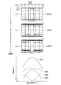
- Example 1 it is explanatory drawing which shows the measurement result of the magnetic field distribution on the central axis of the bulk magnet structure in each process of magnetization. It is a schematic sectional drawing which shows the structure of the bulk magnet structure made into the magnetization object in Example 3.
- FIG. It is a schematic sectional drawing which shows the structure of the bulk magnet structure made into the magnetization object in Example 4.
- FIG. In Example 4, it is a schematic sectional drawing which shows the structure of the two bulk magnets arrange
- FIG. In Example 5 it is a schematic sectional drawing which shows the structure of the disk shaped bulk magnet provided in one end side. It is explanatory drawing which shows schematic structure of the magnetization system for magnetizing the bulk magnet structure shown to FIG. 21A.
- the oxide superconducting bulk body used in the embodiment of the present invention has a structure in which a non-superconducting phase typified by a RE 2 BaCuO 5 phase (211 phase) or the like is finely dispersed in a single crystalline REBa 2 Cu 3 O 7-x. It may be a thing (so-called QMG (registered trademark) material).
- QMG registered trademark
- single crystal means that it is not a perfect single crystal, but also includes those having defects that may impede practical use, such as a low-angle grain boundary.
- the RE in the REBa 2 Cu 3 O 7-x phase (123 phase) and the RE 2 BaCuO 5 phase (211 phase) is Y, La, Nd, Sm, Eu, Gd, Dy, Ho, Er, Tm, Yb, Lu.
- the 123 phase containing La, Nd, Sm, Eu, and Gd is out of the 1: 2: 3 stoichiometric composition, and Ba is partially substituted at the RE site.
- the 211 phase which is a non-superconducting phase La and Nd are somewhat different from Y, Sm, Eu, Gd, Dy, Ho, Er, Tm, Yb and Lu, and the ratio of metal elements is non-stoichiometric. It is known that it has a theoretical composition or a different crystal structure.
- substitution of the Ba element described above tends to lower the critical temperature. Further, in an environment with a lower oxygen partial pressure, substitution of Ba element tends to be suppressed.
- the 123 phase is a peritectic reaction between the 211 phase and a liquid phase composed of a composite oxide of Ba and Cu.
- the temperature at which the 123 phase is formed by this peritectic reaction (Tf: 123 phase formation temperature) is substantially related to the ionic radius of the RE element, and Tf also decreases as the ionic radius decreases. Further, Tf tends to decrease with the addition of a low oxygen atmosphere and Ag.
- a material in which the 211 phase is finely dispersed in the single-crystal 123 phase can be formed because 211 unreacted grains are left in the 123 phase when the 123 phase is crystal-grown. That is, the oxide superconducting bulk is 211 phase + liquid phase (complex oxide of Ba and Cu) ⁇ It can be performed by the reaction shown by 123 phase + 211 phase.
- Fine dispersion of the 211 phase in the oxide superconducting bulk material is extremely important from the viewpoint of improving Jc.
- a trace amount of at least one of Pt, Rh or Ce the grain growth of the 211 phase in the semi-molten state (a state consisting of the 211 phase and the liquid phase) is suppressed, and as a result, the 211 phase in the material is reduced to about The size is reduced to about 1 ⁇ m.
- the addition amount is 0.2 to 2.0% by mass for Pt, 0.01 to 0.5% by mass for Rh, and 0.5 to 2.0% for Ce from the viewpoint of the amount of the effect of miniaturization and material cost. The mass% is desirable.
- the added Pt, Rh, and Ce partially dissolve in the 123 phase.
- elements that could not be dissolved form a composite oxide with Ba and Cu and are scattered in the material.
- the bulk oxide superconductor constituting the magnet needs to have a high critical current density (Jc) even in a magnetic field.
- Jc critical current density
- the phase is a single-crystal 123 phase that does not include large-angle grain boundaries that are superconductively weakly coupled.
- a pinning center for stopping the movement of magnetic flux is required. What functions as the pinning center is a finely dispersed 211 phase, and it is desirable that many finely dispersed.
- Pt, Rh, and Ce have a function of promoting the refinement of the 211 phase.
- the non-superconducting phase such as the 211 phase has an important function of mechanically strengthening the superconductor by being finely dispersed in the 123 phase that is easy to cleave, and as a bulk material.
- the ratio of the 211 phase in the 123 phase is preferably 5 to 35% by volume from the viewpoint of Jc characteristics and mechanical strength.
- the material generally contains 5 to 20% by volume of voids (bubbles) of about 50 to 500 ⁇ m.
- voids bubbles
- the oxygen deficiency (x) of the material after crystal growth is about 0.5, indicating a temperature change in semiconductor resistivity. This is annealed in an oxygen atmosphere at 350 ° C. to 600 ° C. for about 100 hours by each RE system, so that oxygen is taken into the material, and the amount of oxygen deficiency (x) is 0.2 or less, resulting in excellent superconducting characteristics. Show. At this time, a twin structure is formed in the superconducting phase. However, including this point, it is referred to as a single crystal here.
- FIG. 1 is an explanatory diagram showing a schematic configuration of a magnetization system 1 for magnetizing a bulk magnet structure according to this embodiment.
- the magnetization system 1 according to the present embodiment includes a magnetic field generator 5, a vacuum heat insulating container 10 in which a bulk magnet structure 100 is accommodated, a cooling device 20, and a temperature control device 30. It is comprised including.
- the magnetic field generator 5 is an apparatus that generates an applied magnetic field (external magnetic field) for applying a magnetic field to the bulk magnet structure 50.
- a cylindrical superconducting magnet 7 is accommodated in the magnetic field generator 5, and a vacuum heat insulating container 10 can be disposed in the hollow portion.
- a bulk magnet structure 50 is accommodated in the vacuum heat insulating container 10.
- the bulk magnet structure 50 is placed in the vacuum heat insulating container 10 while being placed on the cold head 21 of the cooling device 20.
- the bulk magnet structure 50 is thermally connected to the cooling device 20 and can be cooled by the cooling device 20.
- the cold head 21 is provided with a heater 23 for increasing the temperature of the bulk magnet structure 50.
- the temperature sensor may be installed near the upper part of the vacuum heat insulating container 10 or near the cold head 21 on which the bulk magnet structure 50 is placed.
- the cooling device 20 is a device that cools the bulk magnet structure 50.
- a refrigerant such as liquid helium or liquid neon, a GM refrigerator (Gifford-McMahonercooler), a pulse tube refrigerator, or the like can be used.
- the cooling device 20 is controlled and driven by the temperature control device 30.
- the temperature control device 30 controls the cooling device 20 so that the temperature of the bulk magnet structure 50 becomes a desired temperature according to each step of magnetization.
- a magnetic field distribution uniformity evaluation index a ratio of the difference between the maximum magnetic field strength and the minimum magnetic field strength with respect to the average magnetic field strength in a certain region is displayed in ppm.
- a high magnetic field uniformity of about ppm order is often required as an index for evaluating the uniformity of the applied magnetic field distribution.
- the uniformity of the magnetic field that can be generated by a magnetic field generator that is not mainly intended to generate a magnetic field with high uniformity of NMR or MRI is relatively non-uniform, and is required in the magnetic field homogenization region.
- the magnetization method of the present invention is applied using a relatively inexpensive magnetic field generator in which the uniformity evaluation index of the applied magnetic field distribution before magnetization in the magnetic field homogenization region is 100 ppm or more, the merit is Large and preferred.
- the uniformity evaluation index of the magnetic field distribution of the magnetized bulk magnet structure is more preferably less than 100 ppm, and even more preferably 50 ppm or less.
- this magnetization method exhibits high effectiveness. Needless to say.
- the magnetic field strength at a certain point can be roughly obtained based on the Hall element, a highly sensitive magnetic field measuring device (for example, Teslameter (manufactured by Metrolab)), the half width of the NMR signal, or the like.
- the maximum magnetic field strength and the minimum magnetic field strength are the highest magnetic field strength value and the lowest magnetic field strength value in a certain region, and the average magnetic field strength is an average value of the maximum magnetic field strength and the minimum magnetic field strength.
- the distribution of the applied magnetic field generated by the external magnetic field generator 5 is not changed, and the bulk magnet structure is magnetized using a non-uniform static magnetic field,
- the purpose is to obtain a uniform magnetic field.
- the peak of the magnetic field distribution in the bulk magnet structure magnetized by the applied magnetic field is made smaller than the peak of the applied magnetic field (for example, about 1/5 or less), so that the axial direction
- the magnetic field distribution of the bulk magnet structure within a predetermined range is made uniform.
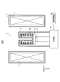
- FIG. 3A is an explanatory diagram showing an example of a magnetization method used for magnetization of a conventional bulk NMR magnetic compact structure.
- FIG. 3B is an explanatory diagram showing a method for magnetizing a bulk magnet structure according to an embodiment of the present invention.
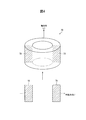
- FIG. 4 is an explanatory view showing an external view and a cross-sectional view of the ring-shaped oxide superconducting bulk body.
- 5A to 5C are conceptual diagrams of current distribution and magnetic field distribution of the oxide superconducting bulk body under the magnetization conditions 1 to 3.
- the ring-shaped oxide superconducting bulk body is also referred to as a “ring-shaped bulk body”.
- the solid line indicates the temperature of the bulk magnet structure controlled by the temperature controller
- the broken line indicates the magnetic field strength of the applied magnetic field generated by the magnetic field generator.
- the conventional method of magnetizing a bulk magnet structure first generates an applied magnetic field to be applied to the bulk magnet structure by a magnetic field generator as a pre-magnetization step, thereby obtaining a predetermined magnetic field strength. Increase the magnetic field strength.
- the temperature control device starts cooling the bulk magnet structure so that the temperature becomes a predetermined temperature (magnetization temperature) equal to or lower than the superconducting transition temperature (Tc). And if it cools to the magnetization temperature, a magnetic field generator will reduce an applied magnetic field gradually and will perform the magnetization process of a bulk magnet structure.
- the state until the demagnetization (that is, the magnetization process of the bulk magnet structure) by the magnetic field generator is started as a pre-magnetization state.
- temperature control is performed to suppress flux creep that reduces the magnetic flux trapped in the bulk magnet structure.
- the temperature is further lowered from the magnetization temperature to a predetermined temperature, and the magnetic field distribution copied to the bulk magnet structure is stabilized.
- the state after the temperature is lowered to a predetermined temperature in order to suppress flux creep is defined as a post-magnetization state.
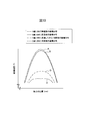
- the magnetization method shown in FIG. 3A when an applied magnetic field as shown on the left side of FIG. 2 is applied to the bulk magnet structure, the same magnetic field distribution is copied to the bulk magnet structure, resulting in a non-uniform magnetic field distribution. Therefore, in the magnetization method according to the present embodiment, as shown in FIG. 3B, after the demagnetization, the bulk magnet structure is once heated or a step of holding a predetermined temperature higher than the target magnetization temperature is performed. Thereafter, a cooling process for suppressing flux creep is performed to uniform the magnetic field distribution in at least a part of the axial range of the bulk magnet structure.
- FIGS. 4 and 5A to 5C are basic magnetization steps in which the magnetic field applied to the bulk magnet structure in the normal state is cooled after being brought into the superconducting state under the respective magnetization conditions, and then the applied magnetic field is removed.
- the magnetized state in the bulk magnet structure is shown.
- 5A to 5C show a region 72a in which no superconducting current flows and a region 72b in which superconducting current flows, using the cross section 72 of the oxide superconducting bulk body 70 in the axial and radial directions shown in FIG. The critical current density distribution and the magnetic field distribution in the cross section are also shown.
- FIG. 5A shows the distribution of the superconducting current and the magnetic field distribution in the oxide superconducting bulk at this time. State A is a state before demagnetization, and no superconducting current flows in the oxide superconducting bulk body.
- the applied magnetic field is identical to the magnetization condition 1 and a temperature T h higher than the temperature T S at the magnetizing conditions 1 oxide superconducting bulk body.
- the oxide superconductivity is similar to the magnetization condition 1 in the state A before demagnetization. There is no superconducting current in the bulk.
- the magnetic flux density gradient is proportional to the critical current density Jc.
- the critical current density Jc is shown to be constant (that is, does not change) with respect to the temperature, and the three magnetization conditions are shown.
- the critical current density Jc decreases logarithmically with time. Therefore, the magnetic flux trapped in the ring-shaped oxide superconducting bulk decreases with time. Such a phenomenon that gradually decreases with time is called creep.
- FIGS. 5A to 5C a conceptual diagram of a ring-shaped oxide superconducting bulk body that is sufficiently long in the axial direction is shown, but since the actual length is finite, the bulk magnet located at the end in the axial direction On the other hand, there is no adjacent bulk magnet. For this reason, the magnetic field suddenly decreases and the magnetic field gradient increases, so that a large critical current flows, and accordingly, a region where the critical current flows flows toward the inner periphery. As a result, the critical current density Jc distribution in the cross section of the oxide superconducting bulk body becomes a distribution that penetrates more inside at the upper and lower ends, and the magnetic field strength captured at the upper and lower ends also decreases.
- the axis of the bulk magnet structure is used. Control at least one of the temperature control device or the magnetic field generator so that the magnetic field distribution of at least a part of the region in the direction becomes a magnetic field homogenization region that is more uniform than the applied magnetic field distribution before magnetization, Magnetize the bulk magnet structure.
- magnetization is a process in which a superconducting bulk body is magnetized by a superconducting current induced by changing an applied magnetic field in a superconducting state, and the superconducting bulk body functions as a magnet. It is.
- this magnetization process is called a basic magnetization process.
- the non-uniform applied magnetic field distribution that magnetizes the oxide superconducting bulk body has, for example, a peak of the applied magnetic field distribution at the center in the axial direction, as shown on the left side of FIG. In the 10 mm range, there is a difference in magnetic field strength of about 500 ppm.
- the distribution of the applied magnetic field is a distribution on the symmetry axis (Z axis) of the winding wound in a substantially concentric cylindrical shape.
- the applied magnetic field is generally generated by a magnet of a superconducting magnet (such as for general-purpose experiments) other than the superconducting magnet for NMR that requires high uniformity.
- the bulk magnet structure was magnetized in an applied magnetic field of uniformity on the order of ppm by a superconducting magnet for NMR. Accordingly, a highly uniform applied magnetic field (generally on the order of ppm) is copied into the bulk magnet structure.
- at least one of the temperature control device and the magnetic field generation device is controlled in the non-uniform applied magnetic field distribution, and at least a part of the region in the axial direction of the bulk magnet structure is controlled.
- the magnetic field distribution can be made more uniform than the applied magnetic field distribution before magnetization. For example, as shown on the right side of FIG.
- the peak of the magnetic field strength at the central portion in the axial direction becomes small, and the magnetic field uniformity can be greatly improved.
- a magnetic field distribution in a bulk magnet structure after magnetization can be greatly improved with respect to a non-uniform applied magnetic field distribution before magnetization, and a method for magnetization thereof. Is the essence of the present invention.
- a magnet for generating a desired magnetic field space for example, a magnet for experiment, NMR, MRI, etc.
- the magnetic field strength, the spatial uniformity of the magnetic field, and the volume of the magnetic field uniform space are important indicators.
- Magnets for NMR and MRI are required to have high magnetic field uniformity compared to general experimental magnets.
- the MRI magnet is larger in size than the NMR magnet, so that a wide magnetic field uniform space is required.
- the degree of uniformity may be about an order of magnitude lower due to the difference in measurement technique.
- general-purpose experimental magnets are inexpensive because they do not require high uniformity.
- a magnet designed based on such a concept generally has a structure in which a coil is concentrically wound and the symmetry (axial symmetry, symmetry of the shaft in two directions) is enhanced as much as possible.
- the inner diameter of the ring-shaped bulk body corresponding to the region where the magnetic field distribution is desired to be uniform (magnetic field homogenization region) It is configured to be larger than the inner diameter of the other ring-shaped bulk body.
- the ring-shaped bulk body corresponding to the region where the magnetic field distribution is desired to be uniformed may be located at the central portion of the bulk magnet structure in the stacking direction.
- the central portion in the stacking direction of the ring-shaped oxide superconducting bulk body may be read as the portion corresponding to the measurement portion of the ring-shaped oxide superconducting bulk body.
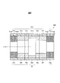
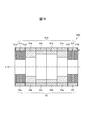
- a bulk magnet structure 50A shown in FIG. 6 has a plurality of ring-shaped bulk bodies 51A to 51g and a plurality of ring-shaped bulk bodies 51A to 51g and a plurality of ring-shaped bulk bodies 51a to 51g fitted on the outer periphery. And an outer peripheral reinforcing ring portion 53 including outer peripheral reinforcing rings 53a to 53g.
- the bulk magnet structure 50A is configured by laminating the ring-shaped bulk bodies 51a to 51g with the central axes thereof aligned.
- the ring-shaped bulk bodies 51a to 51g have the same outer diameter, but are stacked so that the inner diameter increases toward the center in the axial direction (that is, the radial thickness decreases).
- the inner diameters of the ring-shaped bulk bodies 51a and 51g located at both ends in the axial direction are the smallest, and the inner diameter of the ring-shaped bulk body 51d at the center is the largest.
- the inner diameters of the ring-shaped bulk bodies 51b, 51c, 51e, 51f are set to be smaller than the maximum inner diameter and larger than the minimum inner diameter.
- a large electromagnetic force can act on the ring-shaped bulk body.
- a stress that causes breakage occurs in the ring-shaped bulk body, such as a circumferential pulling force (hoop force) to inflate the ring-shaped bulk body.
- the bulk magnet structure according to an aspect of the present invention includes an outer peripheral reinforcing ring.
- an outer peripheral reinforcing ring By providing the outer peripheral reinforcing ring, even when a large electromagnetic force (stress) is applied to the ring-shaped bulk body, the ring-shaped bulk body can be prevented from being broken.
- the bulk magnet structure 50A shown in FIG. 6 magnetization is performed in the process shown in FIG. 3B so as to make the magnetic field distribution uniform in the vicinity of the ring-shaped bulk body 51d having the maximum inner diameter. Is called. That is, the bulk magnet structure 50A including the ring-shaped bulk body portion 51A composed of the plurality of ring-shaped bulk bodies 51a to 51g shown in FIG. 6 is placed on the cold head in the heat insulating vacuum vessel. To make a non-full magnetization state in which the magnetic field distribution of the entire bulk magnet structure hardly changes.
- the temperature of the bulk magnet structure is gradually raised, and at least only the central ring-shaped bulk body 51d having a small thickness in the radial direction is fully magnetized, and then cooling for suppressing flux creep is performed.
- the magnetic flux density which is too high in the ring-shaped bulk body in the axially central portion in the fully magnetized state can be reduced and the magnetic flux density can be made uniform.
- the inner diameter of 51d shown in FIG. 6 is the same as 51b, 51c, 51e, 51f (that is, the axial height from 51b to 51f is 80 mm), state D in FIG.
- the homogenization of the magnetic field does not occur.
- the thickness (height) of 51d in the Z-axis direction at which uniformization occurs as in state B depends on the shape of the magnetic field distribution to be applied.
- the thickness (height) in the Z-axis direction of each ring-shaped bulk body such as 51d may be 10 mm to 30 mm. Within this range, it is possible to easily obtain a uniform magnetic field according to the present invention.
- the axial length of the sample tube used for NMR spectroscopy is generally about 20 mm, and the uniformity of the magnetic field in this region is important.
- the thickness of each ring-shaped bulk body such as 51d in the Z-axis direction is important. When the thickness is 10 mm to 30 mm, uniformization can be achieved more effectively.
- the difference between the inner diameter of 51d in FIG. 6 and the inner diameters of the adjacent 51c and 51e is preferably 1 mm or more from the viewpoint of dimensional accuracy.
- Patent Document 5 is a superconductor having a cylindrical shape with an inner space part of a coaxial core and an axial core having a cylindrical shape,
- the inner space portion includes a central space portion positioned in the center in the direction along the axis, and end space portions positioned on both sides of the central space portion in the direction along the axis.
- the inner dimension of the central space portion in the direction perpendicular to the axis is greater than the inner dimension of the end space portion in the direction perpendicular to the axis.
- the inner space portion has a first angle at which a first surface and a second surface intersect with each other in a posture orthogonal to the axis of the central space portion and a side surface of the two end space portions along the direction of the axis. And a second corner portion where the first surface and the second surface intersect the side surface along the axial direction of the central space portion,
- the second corner portion is a superconductor located in a region where the superconducting current does not flow inside the region where the superconducting current flows inside the superconductor. Is disclosed. In this superconductor, the entire superconductor is in a non-full magnetized state, and there is no ring-shaped bulk body in a fully magnetized state.
- the second corner portion of Patent Document 5 corresponds to the inner peripheral corner portion of 51d in FIG. 6 according to the present invention, but the inner peripheral corner portion of 51d is in a fully magnetized state, that is, a region where a superconducting current flows. is there.
- the second corner is a boundary (outside) of a region where the superconducting current flows inside the superconductor, and is located in a region (boundary) where the superconducting current flows. Is obtained.
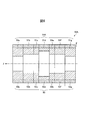
- FIG. 7 shows an example of the magnetic field distribution when the temperature after the basic magnetization process of the bulk magnet structure 50A of FIG. 6 is increased.
- the temperature is raised to a higher temperature in the order of state A, state B, and state C.
- the state A of FIG. 7 there is a region 72a where no superconducting current flows in all of the ring-shaped bulk bodies 51a to 51g.
- the state B first, the most radial direction
- the ring-shaped bulk body 51d having a small thickness becomes a region 72b through which the superconducting current flows, and becomes fully magnetized.
- the ring-shaped bulk bodies 51b, 51c, 51e, and 51f having the smallest radial thickness after the ring-shaped bulk body 51d are fully magnetized.
- the magnetic field strength distribution in a predetermined region in the axial direction can be obtained by raising the temperature from the magnetization temperature to a predetermined temperature.
- the inner diameter of 51d shown in FIG. 6 is the same as 51b, 51c, 51e, 51f, and the axial height from 51b to 51f is 80 mm. In this case, the homogenization of the magnetic field does not occur.
- a ring-shaped bulk body having a small radial thickness is disposed in the region in order to reduce an excessively high magnetic flux density in the central portion in the axial direction of the bulk magnet structure 50 ⁇ / b> A.
- the ring-shaped bulk body in the central portion in the axial direction is configured by alternately stacking the ring-shaped bulk body having a small axial thickness and the first planar ring, thereby reducing the magnetic flux in the central portion.
- the first planar ring may be adopted as a ring-shaped bulk body at the center in the stacking direction axial direction of the bulk magnet structure.
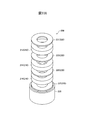
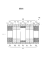
- the bulk magnet structure 50B includes a plurality of ring-shaped bulk bodies 51a to 51c, 51e to 51g, and a laminated body (hereinafter, referred to as a ring-shaped bulk body and a first planar ring). It is also simply referred to as “laminated body.”)
- an outer peripheral reinforcing ring portion 53 of 53 g an outer peripheral reinforcing ring portion 53 of 53 g.
- the bulk magnet structure 50B is configured by laminating the ring-shaped bulk bodies 51a to 51c, 51e to 51g and the laminated body 51d with the central axes thereof aligned.
- Each of the ring-shaped bulk bodies 51a to 51c, 51e to 51g, and the laminated body 51d has the same outer diameter, but the inner diameter increases toward the axial center (that is, the radial thickness decreases). ) Are stacked. Specifically, the inner diameters of the ring-shaped bulk bodies 51a and 51g located at both ends in the axial direction are the smallest, and the inner diameter of the laminated body 51d at the center is the largest. In FIG. 8, the inner diameters of the ring-shaped bulk bodies 51b, 51c, 51e, 51f are set smaller than the maximum inner diameter and larger than the minimum inner diameter.
- the laminated body 51d is configured by alternately laminating ring-shaped bulk bodies 51d1 and first planar rings 51d2 having a small axial thickness. At this time, the ring-shaped bulk body 51d1 is positioned at both axial ends of the multilayer body 51d.
- a superconducting current flows in the cross section of the ring-shaped bulk body 51d1 in an attempt to maintain the magnetic flux density in the central portion, but the amount of current that can maintain the magnetic field in the central portion is equivalent to the presence of the first planar ring 51d2. Less. For this reason, when the temperature rises, the fully magnetized state is reached at an early stage as compared with the ring-shaped bulk body adjacent to the stacked body 51d. Therefore, by gradually raising the temperature, it is possible to reduce the magnetic flux density that is too high in the center and make the magnetic flux density uniform.
- the laminated structure is substantially reduced. It is possible to reduce the average critical current of the bulk magnet structure 50 ⁇ / b> B having, and reach a full magnetization state at an earlier stage than the surrounding bulk magnet. In order to form a region with excellent uniformity in the axial center of the bulk magnet structure 50B, a thin ring-shaped bulk body and a first planar ring are stacked, and a critical current of 51d including these is obtained.
- the thickness of the ring-shaped bulk body and the first planar ring is thinner from the viewpoint of the uniformity of current distribution.
- the thickness of the first planar ring is relatively easy to adjust compared to the ring-shaped bulk body, but the ring-shaped bulk body depends on the diameter (outer diameter) from the viewpoint of processing yield and workability.
- the thickness of the ring-shaped bulk body 51d1 is desirably 5 mm or less, more desirably 2 mm or less, and 0.3 mm or more. This is because when the thickness of the ring-shaped bulk body 51d1 is 0.3 mm or less, cracking easily occurs, and non-uniform characteristics of the ring-shaped bulk body easily occur.
- the first planar ring adjusts the ratio between the ring-shaped bulk body in the bulk magnet including the first planar ring and the first planar ring, and adjusts the cross-sectional area of the superconductor of the bulk magnet. Therefore, the thickness is desirably 5 mm or less, more desirably 2 mm or less, corresponding to the thickness of the ring-shaped bulk body. Further, the first planar ring may be made of a material that is not a superconductor, and may adopt the same configuration as the second planar ring described later.
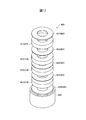
- the bulk magnet structure 50C includes a ring-shaped bulk body 51C composed of a plurality of ring-shaped bulk bodies 51b to 51f and stacked bodies 51a and 51g, and each ring-shaped bulk body 51b to 51f and stacked layers. And an outer peripheral reinforcing ring portion 53 including a plurality of outer peripheral reinforcing rings 53a to 53g fitted to the outer periphery of each of the bodies 51a and 51g.
- the bulk magnet structure 50C is formed by aligning the central axes of the ring-shaped bulk bodies 51b to 51f and the stacked bodies 51a and 51g.
- the ring-shaped bulk bodies 51b to 51f and the stacked bodies 51a and 51g have the same outer diameter, but are stacked so that the inner diameter increases toward the axial center (that is, the radial thickness decreases).
- the inner diameters of the laminated bodies 51a and 51g located at both ends in the axial direction are the smallest, and the inner diameter of the ring-shaped bulk body 51d at the center is the largest.
- the inner diameters of the ring-shaped bulk bodies 51b, 51c, 51e, 51f are set smaller than the maximum inner diameter and larger than the minimum inner diameter.
- the laminated bodies 51a and 51g are configured by alternately laminating ring-shaped bulk bodies 51a1 and 51g1 having a small axial thickness and second planar rings 51a2 and 51g2. At this time, the ring-shaped bulk bodies 51a1 and 51g1 are positioned at both axial ends of the stacked bodies 51a and 51g. This is because both ends in the axial direction of the bulk magnet structure 50C where the stacked bodies 51a and 51g are disposed are the portions where the greatest stress acts, and in particular, the inner surface portion and the vicinity of both end surfaces in the axial direction. Large stress acts. For this reason, it is desirable that the bulk magnet disposed at least at the end of the bulk magnet structure has sufficient mechanical strength.
- the ring-shaped bulk bodies 51a1 and 51g1 are positioned at both axial ends of the stacked bodies 51a and 51g.
- the ring-shaped bulk body disposed other than at both ends in the axial direction is also a laminated body in which the ring-shaped bulk body having a small axial thickness and the second planar ring are alternately stacked. It is desirable to use
- the laminated bodies 51a and 51g constituting the bulk magnet structure 50C shown in FIG. 9 and any one of the ring-shaped bulk bodies 51b to 51f are combined with a ring-shaped bulk body having a small axial thickness and a second planar ring.
- a specific configuration example of the laminated body when alternately arranged will be described with reference to FIGS. 10 to 17D.
- FIG. 10 is a schematic exploded perspective view showing an example of a laminated body according to the first embodiment.
- the bulk magnet 100 includes a ring-shaped bulk body 110 having a through hole in the central portion of the disc, a ring-shaped second flat ring 120 having a through hole in the central portion of the disc, and an outer peripheral reinforcing ring. 130.
- three ring-shaped bulk bodies 112, 114, and 116 are provided as the ring-shaped bulk body 110, and two second planar rings 122 and 124 are provided as the second planar ring 120.
- the ring-shaped bulk body 110 and the second planar ring 120 are alternately stacked in the direction of the central axis of the bulk magnet ring.
- the second planar ring 122 is disposed between the superconducting bulk bodies 112 and 114, and the second planar ring 124 is disposed between the ring-shaped bulk bodies 114 and 116.
- the laminated ring-shaped bulk body 110 and the second planar ring 120 are bonded or bonded, and a hollow metal outer peripheral reinforcing ring 130 is fitted to the outer periphery thereof. In this way, a bulk magnet having a center penetrated is formed.
- Bonding or adhesion between the ring-shaped bulk body 110 and the second planar ring 120 laminated in the central axis direction may be performed by, for example, resin or grease, and more preferably, soldering that provides a stronger bonding force. It is better to do it.
- soldering it is desirable that an Ag thin film is formed on the surface of the ring-shaped bulk body 110 by sputtering or the like, and further annealed at 100 ° C. to 500 ° C. Thereby, the Ag thin film and the ring-shaped bulk body surface are well adapted. Since the solder itself also has a function of improving the thermal conductivity, the soldering process is desirable from the viewpoint of improving the thermal conductivity and making the temperature of the entire bulk magnet uniform.
- the second planar ring 120 is desirably a solderable metal such as an aluminum alloy, a Ni-based alloy, nichrome, or stainless steel. Further, it is more desirable to use nichrome that has a linear expansion coefficient relatively close to that of the ring-shaped bulk body 110 and slightly applies a compressive stress to the ring-shaped bulk body 110 during cooling from room temperature.
- the second planar ring 120 is preferably made of a metal such as copper, copper alloy, aluminum, aluminum alloy, silver, or silver alloy having high thermal conductivity and high electrical conductivity. These metals can be soldered.
- oxygen-free copper, aluminum, and silver are desirable from the viewpoint of thermal conductivity and electrical conductivity. Further, when bonding with solder or the like, it is effective to use the second planar ring 120 having pores in order to suppress entrainment of air bubbles and allow the solder to penetrate uniformly.
- the reinforcement by the second planar ring 120 made of such a metal increases the thermal stability as a whole, thereby increasing the thermal stability as a bulk magnet, making it difficult for quenching to occur, and lower temperature region, that is, high critical current density. High magnetic field magnetization in the Jc region is possible.
- Metals such as copper, aluminum, and silver have high electrical conductivity, so when fluctuations that locally degrade the superconducting properties occur, it can be expected to have a detouring effect on the superconducting current, which is thought to have a quench suppression effect. .
- the contact resistance at the interface between the ring-shaped bulk body and the second plane ring with high electrical conductivity is small, and a silver film is formed on the surface of the ring-shaped bulk body After that, it is desirable to join with solder or the like.
- the proportion of the superconducting material decreases by inserting the second planar ring 120 made of metal, so the proportion of the second planar ring 120 can be determined according to the intended use conditions. That's fine. Further, from the above viewpoint, it is desirable that the second planar ring 120 is formed by combining a plurality of metals having high strength and metals having high thermal conductivity at respective ratios.
- the room temperature tensile strength of the ring-shaped bulk body 110 is about 60 MPa, and the room temperature tensile strength of the solder for attaching the second planar ring 120 to the ring-shaped bulk body 110 is usually less than 80 MPa.
- the 2nd plane ring 120 whose normal temperature tensile strength is 80 Mpa or more is effective as a reinforcement member. Therefore, the second flat ring 120 preferably has a normal temperature tensile strength of 80 MPa or more.
- the thermal conductivity of a metal having high thermal conductivity is preferably 20 W / (m ⁇ K) or more in the temperature range of 20 K to 70 K, and more preferably from the viewpoint of transmission and absorption of heat generated in the superconducting material.
- the outer peripheral reinforcing ring 130 may be formed of a material having a high thermal conductivity in order to enhance the quench suppression effect.
- a material containing a metal such as copper, aluminum or silver having a high thermal conductivity as a main component can be used for the outer periphery reinforcing ring 130.
- the thermal conductivity of the outer peripheral reinforcing ring 130 having a high thermal conductivity is a temperature range of 20K to 70K in which a strong magnetic field can be stably generated by cooling the refrigerator from the viewpoint of transmission and absorption of heat generated in the superconducting material. Is preferably 20 W / (m ⁇ K) or more, and more preferably 100 W / (m ⁇ K) or more.
- the outer peripheral reinforcing ring 130 can be configured by arranging a plurality of rings concentrically. That is, one outer peripheral reinforcing ring is configured as a whole so that the peripheral surfaces of the opposing rings are in contact with each other. In this case, at least one of the rings constituting the outer peripheral reinforcing ring only needs to have a thermal conductivity of 20 W / (m ⁇ K) or more.
- the processing of the second flat ring 120 and the peripheral reinforcing ring 130 is performed by a general machining method.
- the central axes of the inner and outer circumferences of each ring-shaped ring-shaped bulk body 110 are necessary for improving the generated magnetic field strength and improving the uniformity (or symmetry).
- the diameter of the outer periphery of each ring-shaped bulk body 110 and the diameter of an inner periphery are design matters, and do not necessarily need to correspond. For example, in the case of a bulk magnet for NMR or MRI, it may be necessary to arrange a shim coil or the like for improving the magnetic field uniformity near the center.
- the diameter of the outer periphery it is effective to adjust the target magnetic field strength and uniformity by changing the diameter of the outer peripheral portion in order to increase the magnetic field strength at the center and improve the uniformity.
- FIG. 10 shows an example of a bulk magnet composed of three ring-shaped bulk bodies.
- the gist of the present invention is that a ring-shaped bulk body having a relatively low strength and a second flat ring having a relatively high strength. Therefore, the effect of compounding can be achieved by increasing the number of layers.
- the thickness of the ring-shaped bulk body depends on the diameter (outer diameter), but is desirably 10 mm or less, more desirably 6 mm or less, and 1 mm or more.
- the thickness of the bulk magnet disposed at the end of the bulk magnet structure is approximately 30 mm or less, and when the thickness of the ring-shaped bulk body is 1 mm or less, superconductivity is caused by the crystallinity fluctuation of the oxide superconductor. Degradation of characteristics occurs. Further, the thickness of the bulk magnet disposed at the end in the bulk magnet structure is approximately 30 mm or less, and the thickness of the ring-shaped bulk body used is 3 or more. It is desirable that the number is 5 or more.
- the second planar ring adjusts the ratio between the second planar ring and the ring-shaped bulk body in the bulk magnet including the second planar ring, and adjusts the strength of the bulk magnet. Accordingly, the thickness may be adjusted according to the required strength, and is preferably 2 mm or less, and more preferably 1 mm or less.
- the 2nd plane ring 120 is arrange
- the strength can be increased by alternately laminating the ring-shaped bulk body 110 and the second planar ring 120 having relatively low strength against tensile stress to form a composite material.
- the occurrence of quenching can be suppressed by using a material having high thermal conductivity as the second planar ring 120 and the outer peripheral reinforcing ring 130. Thereby, it is possible to prevent the ring-shaped bulk body 110 from being damaged even under high magnetic field strength conditions, to obtain a sufficient amount of total magnetic flux inside the bulk magnet, and further to a bulk magnet with excellent magnetic field uniformity.
- a structure can be provided.
- FIG. 11A is a schematic exploded perspective view showing an example of a laminate according to the second embodiment.
- FIG. 11B is a partial cross-sectional view of the bulk magnet 200 shown in FIG. 11A.
- FIG. 11C is a modification of the second stacked body, and shows a partial cross-sectional view when cut along the central axis of the bulk magnet 200.
- the second laminated body 200 is different from the first laminated body in that a second planar ring 220 is provided at the end in the central axis direction.
- the bulk magnet 200 includes a ring-shaped bulk body 210, a second planar ring 220, and an outer peripheral reinforcing ring 230.
- three ring-shaped bulk bodies 212, 214, and 216 are provided as the ring-shaped bulk body 210, and four second planar rings 221, 223, 225, and 227 are provided as the second planar ring 220.
- the ring-shaped bulk body 210 and the second planar ring 220 are alternately stacked in the center axis direction of the ring.
- the second planar ring 223 is disposed between the ring-shaped bulk bodies 212 and 214
- the second planar ring 225 is disposed between the ring-shaped bulk bodies 214 and 216.
- the ring-shaped bulk body 212 is provided with a second planar ring 221 on the surface opposite to the side where the second planar ring 223 is disposed.
- the ring-shaped bulk body 216 is provided with a second planar ring 227 on the surface opposite to the side where the second planar ring 225 is disposed.
- the positional relationship between the second planar ring 221 at the endmost part, the second planar ring 227 at the other endmost part, and the outer peripheral reinforcing ring 230 is the second planar ring 221, 227 may fit within the outer peripheral reinforcing ring 230.
- FIG. 11B the positional relationship between the second planar ring 221 at the endmost part, the second planar ring 227 at the other endmost part, and the outer peripheral reinforcing ring 230 is the second planar ring 221, 227 may fit within the outer peripheral reinforcing ring 230.
- FIG. 11B the positional relationship between the second planar ring 2
- the outer diameters of the second planar rings 221 and 227 are made substantially the same as the outer diameter of the outer circumferential reinforcing ring 230, and the end surfaces of the outer circumferential reinforcing ring 230 are covered with the second planar rings 221 and 227. May be.
- the laminated ring-shaped bulk body 210 and the second flat ring 220 are bonded or bonded, and a hollow metal outer peripheral reinforcing ring 230 is fitted to the outer periphery thereof. In this way, a bulk magnet having a center penetrated is formed.
- FIG. 11A to 11C show an example in which the second planar rings 221 and 227 are provided at both ends in the central axis direction of the bulk magnet 200.
- the second planar rings 221 and 227 are not necessarily disposed at both ends. There is no need.
- a bulk magnet having a reinforcing member 227 disposed only on the bottom surface of FIG. 11A under the bulk magnet having the second planar ring 221 disposed only on the top surface of FIG. 11A, the top surface and bottom surface as a whole.
- the 2nd plane ring 220 is arrange
- Such a ring-shaped bulk body 210 and the second planar ring 220 are alternately laminated to form a composite material, whereby the strength can be increased.
- by using a material having high thermal conductivity as the second planar ring 220 and the outer peripheral reinforcing ring 230 it is possible to suppress the occurrence of quenching. Thereby, even under high magnetic field strength conditions, damage to the ring-shaped bulk body 210 can be prevented, a sufficient amount of total magnetic flux can be obtained inside the bulk magnet, and the bulk magnet with excellent magnetic field uniformity.
- a structure 200 can be provided.
- FIG. 11A to 11C show the case where one outer peripheral reinforcing ring 230 is provided, the present invention is not limited to such an example.
- three ring-shaped bulk bodies 212, Three outer peripheral reinforcing rings 321, 232, and 233 divided corresponding to 214 and 216 may be provided.
- the second planar rings 221, 223, 225, and 227 extend in the radial direction from the ring-shaped bulk bodies 212, 214, and 216 so that the outer diameters thereof are aligned with the outer peripheral reinforcing rings 321, 232, and 233.
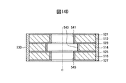
- FIG. 12 is a schematic exploded perspective view showing an example of a laminate according to the third embodiment.
- a bulk magnet 300 that is a laminate according to the third embodiment includes a ring-shaped bulk body 310, a second planar ring 320, and an outer peripheral reinforcing ring 330, as shown in FIG.
- three ring-shaped bulk bodies 312, 314, and 316 are provided as the ring-shaped bulk body 310, and four second planar rings 321, 323, 325, and 327 are provided as the second planar ring 320. Is provided.
- the ring-shaped bulk body 310 and the second planar ring 320 are alternately stacked in the central axis direction of the ring.
- the second planar ring 323 is disposed between the ring-shaped bulk bodies 312 and 314, and the second planar ring 325 is disposed between the ring-shaped bulk bodies 314 and 316.
- the ring-shaped bulk body 312 is provided with a second planar ring 321 on the surface opposite to the side where the second planar ring 323 is disposed.
- the ring-shaped bulk body 316 is provided with a second planar ring 327 on the surface opposite to the side where the second planar ring 325 is disposed.
- the bulk magnet 300 according to the present embodiment has a thickness of at least one of the second flat rings 321 and 327 on the uppermost surface or the lowermost surface of FIG. It is thicker than the thickness of the second planar rings 323 and 325. This is because maximum stress is applied to the upper and lower surfaces of the bulk magnet 300 during the magnetization process, and it is necessary to sufficiently reinforce this portion. Like the bulk magnet 300 according to this embodiment, by increasing the thickness of the reinforcing members 321 and 327 on the uppermost surface or the lowermost surface of the bulk magnet 300, it is possible to ensure sufficient strength to withstand the maximum stress.
- a bulk magnet in which the second planar ring 321 is disposed only on the uppermost surface in FIG. 12 and a bulk magnet in which the reinforcing member 327 is disposed only on the lowermost surface in FIG. By arranging in the structure, a bulk magnet structure in which the second planar rings 321 and 327 are arranged on both the uppermost surface and the lowermost surface of the bulk magnet structure as a whole may be configured.
- FIG. 13 is a schematic exploded perspective view showing an example of a laminated body according to the fourth embodiment.
- a bulk magnet 400 that is a laminate according to the fourth embodiment includes a ring-shaped bulk body 410, a second planar ring 420, and an outer peripheral reinforcing ring 430.
- a ring-shaped bulk body 410 In the fourth stacked body, four ring-shaped bulk bodies 412, 414, 416, 418 are provided as the ring-shaped bulk body 410, and five second planar rings 421, 423, 425, 427, and 429 are provided.
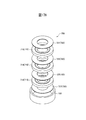
- the inner diameter of the second planar ring 420 is smaller than the inner diameter of the ring-shaped bulk body 410 as compared with the first to third laminated bodies.
- the inner peripheral surface of the ring-shaped bulk body 410 is a portion where stress is concentrated in the magnetization process. When a crack occurs in the bulk magnet 400, it often occurs from this portion.
- the inner diameter of the second flat ring 420 needs to be smaller than the smaller inner diameter when the inner diameters of the upper and lower ring-shaped bulk bodies 410 are different.
- the starting point of the crack in the ring-shaped bulk body 410 is on the inner peripheral surface, and it is desirable to reinforce the intersection line portion between the upper surface or the lower surface and the inner peripheral surface. Therefore, the ring-shaped bulk body 410 having a smaller inner diameter can be reinforced by making the inner diameter of the second planar ring 420 smaller than the ring-shaped bulk body 410 having a smaller inner diameter. Furthermore, by using a material having high thermal conductivity as the second planar ring 420 and the outer peripheral reinforcing ring 430, occurrence of quench can be suppressed.
- FIG. 14A is a schematic exploded perspective view showing an example of a laminate according to the fifth embodiment.
- 14B to 14E are modification examples of the multilayer body according to the fifth embodiment, and show partial sectional views when cut along the central axis of the bulk magnet 500.
- the bulk magnet 500 which is the fifth laminate includes a ring-shaped bulk body 510, a second flat ring 520, an outer peripheral reinforcing ring 530, and an inner peripheral reinforcing ring 540.
- a ring-shaped bulk body 510 two ring-shaped bulk bodies 512 and 514 are provided as the ring-shaped bulk body 510, and three second planar rings 521, 523, and 525 are provided as the second planar ring 520.
- two inner peripheral reinforcing ring 540 two inner peripheral reinforcing rings 542 and 544 are provided.
- the bulk magnet 500 which is the fifth stacked body includes an inner peripheral reinforcing ring 540 for reinforcing the inner peripheral surface of the ring-shaped bulk body 510.
- the difference is that it is bonded or adhered to the inner peripheral surface of 510.
- the inner peripheral reinforcing ring 540 is also bonded or bonded to the second planar ring 520, the ring-shaped bulk body 510 and the second planar ring 520 can be used even when the linear expansion coefficient is larger than that of the ring-shaped bulk body 510. It can be firmly bonded to the inner peripheral surface of the. Therefore, these inner peripheral surfaces can be reinforced and have an effect of suppressing cracking.
- the 2nd plane ring 520 and the outer periphery reinforcement ring 530 can be comprised similarly to the said 1st laminated body.
- a material containing a metal such as copper, aluminum, silver, etc. having high thermal conductivity as a main component can be used for the inner peripheral reinforcement ring 540.
- the thermal conductivity of the inner peripheral reinforcing ring 540 having high thermal conductivity is a temperature of 20K to 70K that can generate a strong magnetic field stably by cooling the refrigerator, etc. from the viewpoint of transmission and absorption of heat generated in the superconducting material.
- 20 W / (m ⁇ K) or more is desirable in the region, and more desirably 100 W / (m ⁇ K) or more.
- the inner peripheral reinforcing ring 540 can be configured by arranging a plurality of rings concentrically. That is, one inner peripheral reinforcement ring is configured as a whole so that the peripheral surfaces of the opposing rings are in contact with each other. In this case, at least one of the rings constituting the inner peripheral reinforcing ring only needs to have a thermal conductivity of 20 W / (m ⁇ K) or more.
- the inner peripheral surface of the ring-shaped bulk body 510 and the outer peripheral surface of the inner peripheral reinforcing ring 540 are brought into close contact with each other.
- the inner diameters of the ring-shaped bulk body 510 and the second planar ring 520 are the same.
- Two inner peripheral reinforcing rings 541 may be provided.
- the inner diameter of the second flat ring 520 is made slightly smaller than the inner diameter of the ring-shaped bulk body 510, and the inner peripheral surface of each of the ring-shaped bulk bodies 512, 514, 516 is reinforced. Rings 541, 543, and 545 may be provided, and the inner diameters of the second planar rings 521, 523, and 525 may be the same as the inner diameters of the inner peripheral reinforcing rings 541, 543, and 545.
- the thickness of the inner peripheral reinforcing ring 540 is larger than the thickness of the second planar ring 520, the configuration shown in FIG. 14C is desirable from the viewpoint of strength.
- the contact area of the inner periphery reinforcement ring 540 and the 2nd plane ring 520 can be enlarged, and the intensity
- the inner peripheral reinforcing ring 540 is divided into inner peripheral reinforcing rings 541, 543, and 545 as shown in FIG. 14D from the viewpoint of workability. It is desirable to be.
- FIG. 14E show the case where one outer peripheral reinforcing ring 530 is provided, but the present invention is not limited to such an example.
- three ring-shaped bulk bodies 512, Three outer peripheral reinforcing rings 531, 532, and 533 divided corresponding to 514 and 516 may be provided.
- the second flat rings 521, 523, 525, and 527 extend in the radial direction from the ring-shaped bulk bodies 512, 514, and 516 so that the outer diameters of the second flat rings 521, 523, 525, and 527 are aligned with the outer peripheral reinforcing rings 531, 532, 533.
- 15A to 15C are partial cross-sectional views taken along the central axis of the multilayer body 600 according to the sixth embodiment.
- a bulk magnet 600 that is a laminate according to the sixth embodiment includes a ring-shaped bulk body 610, a second planar ring 620, an outer peripheral reinforcing ring 6300, a second outer peripheral reinforcing ring 6310, an inner peripheral reinforcing ring 6400, It consists of a second inner periphery reinforcing ring 6410.
- five ring-shaped bulk bodies 611 to 615 are provided as the ring-shaped bulk body 610
- six second planar rings 621 to 626 are provided as the second planar ring 620.
- the outer peripheral end of the second planar ring 620 is coupled with the second outer peripheral reinforcing ring and the outer peripheral reinforcing ring as compared with the first to fifth laminated bodies.
- the second outer peripheral reinforcing ring, the outer peripheral reinforcing ring, the second inner peripheral reinforcing ring, and the inner peripheral reinforcing ring can use metal, they can be firmly connected to the second flat metal ring by solder or the like. is there.
- the ring-shaped bulk bodies 611 to 615 are firmly coupled from the two directions of the side surface and the upper and lower surfaces by the second inner peripheral reinforcing ring, the inner peripheral reinforcing ring, the second outer peripheral reinforcing ring, and the outer peripheral reinforcing ring having a double structure. Can do. Due to this effect, the ring-shaped bulk body 610 can be firmly coupled to the surrounding second flat ring, the second inner peripheral reinforcing ring, and the second outer peripheral reinforcing ring, and has a remarkable effect of suppressing cracking.
- the second planar ring 620, the outer peripheral reinforcing ring 6300, and the second outer peripheral reinforcing ring 6310 can be configured in the same manner as the first laminate.
- the second inner peripheral reinforcing ring 6410 and the inner peripheral reinforcing ring 6400 for example, a material containing, as a main component, a metal such as copper, aluminum, silver or the like having high thermal conductivity is used in order to enhance the quench suppression effect. be able to.
- the thermal conductivity of the second inner circumferential reinforcing ring 6410 and the inner circumferential reinforcing ring 6400 having high thermal conductivity is stable and strong magnetic field by cooling the refrigerator, etc. from the viewpoint of transmission and absorption of heat generated in the superconducting material. 20 W / (m ⁇ K) or more is desirable in the temperature range of 20 K to 70 K where it is possible to generate the pressure, and more desirably 100 W / (m ⁇ K) or more.
- the second inner peripheral reinforcing ring 6410 and the inner peripheral reinforcing ring 6400 can be configured by arranging a plurality of rings concentrically. That is, one second inner peripheral reinforcing ring 6410 and one inner peripheral reinforcing ring 6400 are configured as a whole so that the peripheral surfaces of the opposing rings are in contact with each other. In this case, at least one of the materials constituting the second inner peripheral reinforcing ring 6410 and the inner peripheral reinforcing ring 6400 only needs to have a thermal conductivity of 20 W / (m ⁇ K) or more.
- FIG. 15B shows an example of a modification of FIG. 15A in which only the outer periphery is coupled from the side surface and the upper and lower surfaces of the outer peripheral end portion of the second flat ring having a double ring structure. This is because the inner peripheral end of the second flat ring may be coupled only from the upper and lower surfaces in the inner peripheral reinforcing ring, for example, when it is necessary to ensure the inner diameter.
- FIG. 15C shows an example of a case where only the inner periphery is coupled from the side surface and the upper and lower surfaces of the inner periphery end portion of the second planar ring having the double ring structure. This is because the outer peripheral end of the second flat ring may be coupled only from the upper and lower surfaces by the outer peripheral reinforcing ring, such as when the outer diameter is restricted by design.
- FIG. 16 is an explanatory diagram showing fluctuations in crystallographic orientation of the ring-shaped bulk body 610.
- the ring-shaped bulk body 610 is a single crystal material, the crystal orientation anisotropy appears as disturbance of the trapped magnetic flux density distribution (deviation from axial symmetry).
- the ring-shaped bulk body 610 may be stacked while shifting the crystal orientation of the ring-shaped bulk body 610.
- Ring bulk body 610 RE 2 BaCuO 5 in the single crystalline RE 1 Ba 2 Cu 3 O y is finely dispersed, generally have a fluctuation in the crystal orientation of the single crystalline RE 1 Ba 2 Cu 3 O y is doing.
- the magnitude of the fluctuation in the c-axis direction is about ⁇ 15 °, and that the c-axis direction here substantially coincides with the inner peripheral axis of each ring means that the deviation of the single direction is about ⁇ 15 °.
- the angle at which the a-axis is shifted depends on the number of stacked layers, but is preferably an angle that is not four-fold symmetrical, such as 180 ° or 90 °.
- the anisotropy of the crystal orientation can be averaged.
- FIG. 17A is a schematic exploded perspective view showing an example of a laminate according to the eighth embodiment.
- FIGS. 17B to 17D are structural examples of the ring-shaped bulk body 710 of the laminated body according to the eighth embodiment, and show plan views of the ring-shaped bulk body 710.
- the bulk magnet 700 which is a laminated body according to the eighth embodiment is different from the first to seventh laminated bodies in that the oxide superconducting bulk body 710 has a multiple ring structure in the radial direction.
- the multiple ring structure refers to a structure in which a plurality of rings are concentrically arranged instead of a single ring in the radial direction.
- a ring-shaped bulk body 710 includes ring-shaped bulk bodies 710a to 710e having different inner diameters and outer diameters and having substantially the same radial width, and a predetermined gap 713 in the radial direction. It is good also as a quintuple ring structure arrange
- a ring-shaped bulk body 710 is a quadruple ring in which ring-shaped bulk bodies 710a to 710c having different inner and outer diameters are arranged concentrically with a predetermined gap 713 in the radial direction. It is good also as a structure.
- the radial width of the ring-shaped bulk body 710c may be larger than the radial widths of the other ring-shaped bulk bodies 710a and 710b.
- the width of each ring is a matter of design.
- the ring-shaped bulk body 710 By laminating the ring-shaped bulk body 710 having such a multi-ring structure, the ring-shaped bulk body 710 tends to reflect the 4-fold symmetry slightly in the superconducting current distribution due to crystal growth accompanied by the 4-fold symmetry.
- the concentric multiple ring shape has the effect of bringing the flow path of the superconducting current induced by magnetization close to axial symmetry. This effect improves the uniformity of the captured magnetic field.
- the bulk magnet 700 having such characteristics is particularly suitable for NMR and MRI applications that require high magnetic field uniformity.
- the ring-shaped bulk body 710 forms concentric circular arc-shaped gaps 713 in one ring, and a plurality of seams 715 in the circumferential direction of the gaps 713 on the same circumference. You may make it provide. Thereby, the assembly work of the bulk magnet 700 can be simplified.
- (Configuration D) As another configuration of the bulk magnet structure according to the present invention, for example, among the bulk magnet structures of the configuration C shown in FIG. 9, at least a ring-shaped bulk body on one end side and a second planar ring are alternately stacked.
- the body may be formed in a columnar shape instead of a ring shape. That is, a laminated body in which cylindrical oxide superconducting bulk bodies and cylindrical planar reinforcing plates are alternately laminated is configured. Thereby, higher mechanical strength can be obtained.
- what is manufactured in a columnar shape is not limited to a laminated body on one end side, and one or a plurality of bulk bodies on the laminated body side may be formed in a cylindrical shape.
- the bulk body corresponding to the region where the magnetic field distribution is desired to be uniform is a ring-shaped bulk body.
- the member on one end side to be manufactured in a columnar shape may be a laminate in which a columnar oxide superconducting bulk body and a columnar planar reinforcing plate are alternately stacked, and only the columnar oxide superconducting bulk body. You may comprise.
- Such a bulk magnet structure can be configured as shown in FIG.
- Example 1 the bulk magnet structure 50A shown in FIG. 6 was magnetized by the method for magnetizing the bulk magnet structure according to one embodiment of the present invention described above. Specifically, as a magnetic field generator, a superconducting magnet having a room temperature bore diameter of 150 mm (JASTEC 10T150) was excited to about 5T to obtain an applied magnetic field for magnetization. The distribution of the applied magnetic field at this time had a shape as shown on the left side of FIG. That is, it was confirmed that the magnetic field intensity of the applied magnetic field has a non-uniform magnetic field distribution of about 500 ppm in a section of about 10 mm on both sides centering on the position where the magnetic field strength is a peak.
- JASTEC 10T150 superconducting magnet having a room temperature bore diameter of 150 mm
- a ring-shaped bulk body having an outer diameter of 60 mm, an inner diameter of 28 mm, and a thickness of 20 mm in which Gd 2 BaCuO 5 was finely dispersed in single-crystal GdBa 2 Cu 3 O y was produced.
- two ring-shaped bulk bodies having an outer diameter of 60 mm, an inner diameter of 36 mm, and a thickness of 20 mm two ring-shaped bulk bodies having an outer diameter of 60 mm, an inner diameter of 36 mm, and a thickness of 10 mm, an outer diameter of 60 mm, an inner diameter of the same structure.
- One ring-shaped bulk body having a thickness of 44 mm and a thickness of 20 mm is prepared, and an outer peripheral reinforcing ring made of aluminum alloy (A5104) with an outer diameter of 80 mm and an inner diameter of 60 mm is fitted into each ring-shaped bulk body, and laminated as shown in FIG. Thus, a bulk magnet structure was produced. At this time, grease was put in the gap between the aluminum outer peripheral reinforcing ring and the ring-shaped bulk body, and these were adhered.
- the obtained bulk magnet structure was fixed on a cold head of a cooling device, and after being fitted with a cover of a vacuum heat insulating container, it was cooled to 100K. Then, the cold head portion of the cooling device was inserted into the room temperature bore of the superconducting magnet so that the center of the bulk magnet structure coincided with the center position of the applied magnetic field shown on the left side of FIG. Thereafter, the superconducting magnet was energized so that the central magnetic field of the superconducting magnet was about 5 T, and the superconducting magnet was excited.
- the bulk magnet structure was cooled to 30K, and after the temperature was stabilized, the applied magnetic field of the superconducting magnet was demagnetized to zero magnetic field at 0.05 T / min, and magnetized. Magnetic process). After magnetization, the cold head portion of the cooling device to which the bulk magnet structure was fixed was pulled out from the magnet bore, and the magnetic field distribution on the central axis of the bulk magnet structure was measured. The result is shown by line A in FIG. It can be confirmed that the magnetic field distribution indicated by the A line agrees very well with the applied magnetic field distribution shown on the left side of FIG.
- a bulk magnet structure having a structure in which a plurality of ring-shaped bulk bodies in which Gd 2 BaCuO 5 is finely dispersed in single-crystal Gd 1 Ba 2 Cu 3 O y is laminated.
- the magnetic field strength difference in the same section in the bulk magnet structure can be made uniform within 110 ppm by magnetizing in the external magnetic part distribution having a uniformity of 500 ppm in the section of about 10 mm on both sides of the center of the applied magnetic field.
- Example 2 the bulk magnet structure 50B shown in FIG. 8 was magnetized by the method for magnetizing the bulk magnet structure according to one embodiment of the present invention described above. Specifically, as a magnetic field generator, a superconducting magnet having a room temperature bore diameter of 150 mm (JASTEC 10T150) was excited to about 5T to obtain an applied magnetic field for magnetization. The distribution of the applied magnetic field at this time was a shape as shown on the left side of FIG.
- two ring-shaped bulk bodies having an outer diameter of 60 mm, an inner diameter of 28 mm, and a thickness of 20 mm in which Gd 2 BaCuO 5 was finely dispersed in single-crystal GdBa 2 Cu 3 O y were produced.
- two ring-shaped bulk bodies having an outer diameter of 60 mm, an inner diameter of 36 mm, and a thickness of 20 mm, and two ring-shaped bulk bodies having an outer diameter of 60 mm, an inner diameter of 36 mm, and a thickness of 10 mm having the same structure are produced.
- a silver film was formed on the surface of the bulk body.
- each ring-shaped bulk body was soldered into an outer peripheral reinforcing ring having an outer diameter of 80 mm, an inner diameter of 60 mm, a height of 20 mm, or 10 mm made of an aluminum alloy (A5104), and the ring-shaped bulk body was fitted.
- the ring plate was alternately laminated with a ring-shaped bulk body as a first flat ring and placed in an outer peripheral reinforcing ring made of an aluminum alloy (A5104) having an outer diameter of 80 mm, an inner diameter of 60 mm, and a height of 20 mm. At this time, the outer peripheral reinforcing ring made of aluminum alloy, the ring-shaped bulk body, and the first flat ring made of NiCr were bonded by solder.
- the bulk magnet structure obtained by stacking was fixed on the cold head of the cooling device, and after mounting the cover of the vacuum heat insulating container, it was cooled to 100K. Then, the cold head portion of the cooling device was inserted into the room temperature bore of the magnet so that the center of the bulk magnet structure coincided with the center position of the applied magnetic field. Thereafter, energization was performed so that the central magnetic field of the magnet was about 5 T, and the magnet was excited.
- the bulk magnet structure was cooled to 25K, and after the temperature was stabilized, the applied magnetic field of the magnet was demagnetized to zero magnetic field at 0.05 T / min, and magnetization was performed (basic magnetization process) ). After magnetization, the cold head portion of the cooling device was pulled out from the bore of the magnet, and the magnetic field distribution on the central axis of the bulk magnet structure was measured. As a result, it was found that the degree of the magnetic field intensity having a peak at the central portion of the magnetic field slightly decreased with respect to the applied magnetic field distribution, and was made slightly uniform by magnetization.
- the bulk magnet structure was heated to 56K, and the magnetic field distribution on the central axis was measured while the temperature was stable.
- the magnetic field strength was slightly lowered, and when measured again about 1 hour later, the magnetic field strength was lowered and the magnetic field distribution was made uniform at the center of the magnetic field due to the effect of flux creep. . Therefore, in order to prevent a decrease in magnetic field strength due to flux creep, the magnetic field distribution in the axial center was measured again in a state where the temperature was quickly cooled to 30K and the temperature was stable at 30K. As a result, it was confirmed that the difference in magnetic field strength in the section of about 10 mm on both sides of the center of the applied magnetic field was uniformized to within 85 ppm.
- Such a magnetization method has a structure in which a plurality of ring-shaped bulk bodies in which Gd 2 BaCuO 5 is finely dispersed in single-crystal Gd 1 Ba 2 Cu 3 O y are laminated, and By magnetizing a bulk magnet structure having a bulk magnet stacked via a single plane ring in an external magnetic part distribution having a uniformity of 500 ppm in a section of about 10 mm on both sides of the center of the applied magnetic field, It was confirmed that the difference in magnetic field strength in the same section in the structure could be made uniform within 85 ppm.
- Example 3 the bulk magnet structure 50D having the ring-shaped bulk body portion 51D shown in FIG. 19 was magnetized by the method for magnetizing the bulk magnet structure according to one embodiment of the present invention described above. Specifically, as a magnetic field generator, a superconducting magnet having a room temperature bore diameter of 150 mm (JASTEC 10T150) was excited to about 6T to obtain an applied magnetic field for magnetization. The distribution of the applied magnetic field at this time was a shape as shown on the left side of FIG.
- a reinforced bulk magnet was produced using a ring-shaped bulk body having an outer diameter of 60 mm, an inner diameter of 28 mm, and a thickness of 2 mm.
- 12 SUS316L plates having an outer diameter of 60 mm, an inner diameter of 27.8 mm, and a thickness of 0.6 mm, an outer diameter of 80 mm, an inner diameter of 27.8 mm, Four SUS316L plates having a thickness of 0.8 mm were produced.
- two types of 2nd plane rings from which an outer diameter differs are represented by the same shape, and are shown as 2nd plane rings 51a2 and 51f2.
- two outer peripheral reinforcing rings made of an aluminum alloy (A5104) having an outer diameter of 80 mm, an inner diameter of 60 mm, and a height of 18.5 mm are produced, and ring-shaped bulk bodies 51a1 and 51f1 having a thickness of 2.0 mm are formed in the outer peripheral reinforcing ring.
- two second flat rings 51a2, 51f2 having an outer diameter of 60 mm are alternately laminated, and further, a second flat ring made of a SUS316L plate having an outer diameter of 80 mm, an inner diameter of 27.8 mm, and a thickness of 0.8 mm. Were placed at both ends to produce two sets of laminates 51a and 51f.
- the outer peripheral reinforcing ring corresponds to the outer peripheral reinforcing rings 53a and 53f in FIG.
- the second flat ring having an outer diameter of 80 mm was arranged so as to cover both end faces of the outer peripheral reinforcing rings 53a and 53f.
- the ring-shaped bulk body in the outer periphery reinforcement ring made from one aluminum alloy (A5104) and the 2nd plane ring made from SUS316L were adhere
- the six bulk magnets thus obtained were stacked as shown in FIG. 19 to produce a bulk magnet structure 50D having a ring-shaped bulk body portion 51D.
- the bulk magnet structure 50D obtained by laminating was fixed on the cold head of the cooling device, and after mounting the cover of the vacuum heat insulating container, it was cooled to 100K.
- the cold head portion of the cooling device was inserted into the room temperature bore of the magnet so that the center of the bulk magnet structure 50D coincided with the center position of the applied magnetic field. Thereafter, energization was performed so that the central magnetic field of the magnet was about 6 T, and the magnet was excited.
- the bulk magnet structure 50D was cooled to 25K, and after the temperature was stabilized, the applied magnetic field of the magnet was demagnetized to a zero magnetic field at 0.05 T / min, and magnetized.
- the cold head portion of the cooling device was pulled out from the bore of the magnet, and the magnetic field distribution on the central axis of the bulk magnet structure 50D was measured. As a result, it was found that a magnetic field distribution of almost the same level as the applied magnetic field distribution was obtained.
- the bulk magnet structure 50D was heated to 52K, and the magnetic field distribution on the central axis was measured while the temperature was stable. As a result, it was confirmed that the magnetic field strength was slightly lowered. When measured again about 1 hour later, the magnetic field strength was lowered at the center of the magnetic field due to the effect of flux creep, and the magnetic field distribution was made uniform. It was. Therefore, in order to prevent a decrease in magnetic field strength due to flux creep, the magnetic field distribution in the axial center was measured again in a state where the temperature was quickly cooled to 30K and the temperature was stable at 30K. As a result, it was confirmed that the difference in magnetic field strength in the section of about 10 mm on both sides of the center of the applied magnetic field was uniformized within 45 ppm.
- Such a magnetization method has a structure in which a plurality of ring-shaped bulk bodies in which Gd 2 BaCuO 5 is finely dispersed in single-crystal Gd 1 Ba 2 Cu 3 O y are stacked, By arranging a bulk magnet reinforced with a second planar ring at the end of the magnet structure 50D, 500 ppm in a section of about 10 mm on both sides of the center of the applied magnetic field without breaking even in 6T strong magnetism. It was confirmed that the difference in the magnetic field strength in the same section in the bulk magnet structure 50D can be made uniform to 45 ppm by magnetizing in the distribution of the external magnetic part having the above uniformity.
- Example 4 the bulk magnet structure 50E shown in FIG. 20A was magnetized by the method for magnetizing the bulk magnet structure according to one embodiment of the present invention described above. Specifically, as a magnetic field generator, a superconducting magnet having a room temperature bore diameter of 150 mm (JASTEC 10T150) was excited to about 7 T to obtain an applied magnetic field for magnetization. The distribution of the applied magnetic field at this time was a shape as shown on the left side of FIG.
- ring-shaped bulk bodies having an outer diameter of 60 mm, an inner diameter of 29 mm, and a thickness of 2 mm in which Eu 2 BaCuO 5 was finely dispersed in single-crystal EuBa 2 Cu 3 O y were produced.
- four ring-shaped bulk bodies having an outer diameter of 60 mm, an inner diameter of 35 mm, and a thickness of 15 mm, and eight ring-shaped bulk bodies having an outer diameter of 60 mm, an inner diameter of 44 mm, and a thickness of 2 mm having the same structure are prepared.
- a silver film was formed on the surface of the ring-shaped bulk body.
- a reinforced bulk magnet was manufactured using a ring-shaped bulk body having an outer diameter of 60 mm, an inner diameter of 29 mm, and a thickness of 2 mm.
- 16 SUS316L plates having an outer diameter of 64 mm, an inner diameter of 26 mm, and a thickness of 0.5 mm were produced as the second planar ring.
- two SUS316L rings with an outer diameter of 80 mm, an inner diameter of 64 mm, and a height of 19 mm were prepared as outer peripheral reinforcing rings, and a Cu ring with an outer diameter of 64 mm, an inner diameter of 60 mm, and a height of 2 mm was prepared as the second outer peripheral reinforcing ring. 14 pieces were produced.
- Each of the inner peripheral reinforcing rings made by bonding was bonded with solder.
- the two bulk magnets 800 arranged at the end of the bulk magnet structure 50E shown in FIG. 20B are the bulk magnet composed of the laminate 51a and the outer peripheral reinforcement ring 53a of FIG. 20A, and the laminate 51g and the outer peripheral reinforcement ring.
- the bulk magnet which consists of 53g is shown in detail.
- the bulk magnet 800 includes a ring-shaped bulk body 810 having an outer diameter of 60 mm, an inner diameter of 29 mm, and a thickness of 2 mm, second planar rings 820 and 830, an outer peripheral reinforcing ring 841, a second outer peripheral reinforcing ring 843, an inner peripheral reinforcing ring 851, and The second inner periphery reinforcing ring 853 is used.
- a silver film is formed on the surface, and nine sheets of an outer diameter of 60 mm, an inner diameter of 43.5 mm, a thickness of 0.
- a 45 mm NiCr ring plate is alternately laminated with the first planar ring 51d2 to form a ring-shaped bulk body 51d, which is arranged in an outer peripheral reinforcing ring 53d made of an aluminum alloy (A5104) having an outer diameter of 80 mm, an inner diameter of 60 mm, and a height of 20 mm.
- the ring 51d1, the NiCr first flat ring, the aluminum alloy outer peripheral reinforcing ring 53d, and the ring-shaped bulk body 51d were bonded together by solder.
- the four ring-shaped bulk bodies 51b, 51c, 51e, 51f having an outer diameter of 60 mm, an inner diameter of 35 mm, and a thickness of 15 mm are each made of an aluminum alloy (A5104) having an outer diameter of 80 mm, an inner diameter of 60 mm, and a height of 15.0 mm.
- the outer peripheral reinforcing rings 53b, 53c, 53e, and 53f were arranged by solder bonding to produce four bulk magnets.
- the seven bulk magnets thus obtained were stacked as shown in FIG. 20A to produce a bulk magnet structure 50E.
- the bulk magnet structure 50E obtained by stacking was fixed on the cold head of the cooling device, and was cooled to 100K after mounting the cover of the vacuum heat insulating container.
- the cold head portion of the cooling device was inserted into the room temperature bore of the magnet so that the center of the bulk magnet structure 50E coincided with the center position of the applied magnetic field. Thereafter, energization was performed so that the central magnetic field of the magnet was about 7 T, and the magnet was excited.
- the bulk magnet structure 50E was cooled to 25K, and after the temperature was stabilized, the applied magnetic field of the magnet was demagnetized to a zero magnetic field at 0.05 T / min and magnetized.
- the cold head portion of the cooling device was pulled out from the bore of the magnet, and the magnetic field distribution on the central axis of the bulk magnet structure 50E was measured. As a result, it was found that a magnetic field distribution of almost the same level as the applied magnetic field distribution was obtained.
- the bulk magnet structure 50E was heated to 51K, and the magnetic field distribution on the central axis was measured while the temperature was stable. As a result, it was confirmed that the magnetic field strength was slightly lowered. When measured again about 1 hour later, the magnetic field strength was lowered at the center of the magnetic field due to the effect of flux creep, and the magnetic field distribution was made uniform. It was. Therefore, in order to prevent a decrease in magnetic field strength due to flux creep, the magnetic field distribution at the axial center was measured again in a state where the temperature was quickly cooled to 35K and the temperature was stabilized at 35K. As a result, it was confirmed that the difference in magnetic field strength in the section of about 10 mm on both sides of the center of the applied magnetic field was uniformized to within 50 ppm.
- Such a magnetization method has a structure in which a plurality of ring-shaped bulk bodies in which Eu 2 BaCuO 5 is finely dispersed in single-crystal Eu 1 Ba 2 Cu 3 O y are laminated, and the bulk
- a bulk magnet reinforced with a second planar ring at the end of the magnet structure 50E 500 ppm in a section of about 10 mm on both sides of the center of the applied magnetic field without breaking even in 7T strong magnetism. It was confirmed that the difference in magnetic field strength in the same section in the bulk magnet structure 50E can be made uniform to 50 ppm by magnetizing in the distribution of the external magnetic part having the above uniformity.
- Example 5 the bulk magnet structure 50F shown in FIG. 21A was magnetized by the method for magnetizing a bulk magnet structure according to one embodiment of the present invention described above. Specifically, as shown in FIG. 21C, the magnetic field generator 5, the vacuum heat insulating container 10 ⁇ / b> B in which the bulk magnet structure 50 ⁇ / b> F is accommodated, the cooling device 20, and the temperature control device 30 are configured. Magnetization was performed using the magnetizing system 1B.
- the magnetization system 1B shown in FIG. 21C has the same configuration as the magnetization system 1 shown in FIG. As shown in FIG. 21C, the bulk magnet structure 50 ⁇ / b> F is placed so that the cylindrical bulk magnet side is in contact with the cold head 21.
- a superconducting magnet having a room temperature bore diameter of 150 mm (JASTEC 10T150) was excited to about 6T to obtain an applied magnetic field for magnetization.
- the distribution of the applied magnetic field at this time was a shape as shown on the left side of FIG.
- Seven ring-shaped bulk bodies having an outer diameter of 60 mm, an inner diameter of 29 mm, and a thickness of 2 mm, in which Gd 2 BaCuO 5 was finely dispersed in single-crystal GdBa 2 Cu 3 O y were produced.
- one ring-shaped bulk body having an outer diameter of 60 mm, an inner diameter of 35 mm, and a thickness of 10 mm having the same structure and two ring-shaped bulk bodies having an outer diameter of 60 mm, an inner diameter of 35 mm, and a thickness of 20 mm having the same structure.
- one cylindrical oxide superconducting bulk body having the same structure and an outer diameter of 60 mm and a thickness of 10 mm was produced.
- ring-shaped bulk bodies having an outer diameter of 60 mm, an inner diameter of 44 mm, and a thickness of 2 mm were produced, and a silver film was formed on the surface of each ring-shaped bulk body. Furthermore, seven cylindrical oxide superconducting bulk bodies having the same structure and an outer diameter of 60 mm and a thickness of 2 mm were produced.
- a reinforced bulk magnet was manufactured using a ring-shaped bulk body having an outer diameter of 60 mm, an inner diameter of 29 mm, and a thickness of 2 mm.
- eight SUS314 plates having an outer diameter of 64 mm, an inner diameter of 26 mm, and a thickness of 0.5 mm were produced as the second planar ring.
- one SUS314 ring having an outer diameter of 80 mm, an inner diameter of 64 mm, and a height of 19 mm is manufactured as an outer peripheral reinforcing ring
- a Cu ring having an outer diameter of 64 mm, an inner diameter of 60 mm, and a height of 2 mm is prepared as the second outer peripheral reinforcing ring. Seven were produced.
- Each of the inner peripheral reinforcing rings was bonded with solder.
- one bulk magnet arranged at the end of the bulk magnet structure was produced.
- a reinforced bulk magnet was produced using a columnar oxide superconducting bulk body having an outer diameter of 60 mm and a thickness of 2 mm.
- eight SUS314 plates having an outer diameter of 64 mm and a thickness of 0.5 mm were produced as planar reinforcing plates.
- seven Cu rings having an outer diameter of 64 mm, an inner diameter of 60 mm, and a height of 2 mm were produced as the second outer peripheral reinforcing ring.
- a columnar bulk magnet 900 disposed at one end of the bulk magnet structure shown in FIG. 21B shows in detail a bulk magnet composed of the laminated body 51a and the outer peripheral reinforcing ring 53a shown in FIG. 21A.
- the bulk magnet 900 includes a columnar oxide superconducting bulk body 910 having an outer diameter of 60 mm and a thickness of 2 mm, a flat reinforcing plate 920, an outer peripheral reinforcing ring 931, and a second outer peripheral reinforcing ring 933.
- a silver film is formed on the surface, and nine sheets of an outer diameter of 60 mm, an inner diameter of 43.5 mm, a thickness of 0.
- a 45 mm SUS316 ring plate is alternately laminated with the first flat ring 51d2 to form a ring-shaped bulk body 51d, which is arranged in an outer peripheral reinforcing ring 53d made of an aluminum alloy (A5104) having an outer diameter of 80 mm, an inner diameter of 60 mm, and a height of 20 mm.
- the ring 51d1 and the first flat ring 51d2 made of NiCr, the outer peripheral reinforcing ring 53d made of aluminum alloy, and the ring-shaped bulk body 51d were bonded by solder.
- the seven bulk magnets thus obtained were laminated as shown in FIG. 21A to produce a bulk magnet structure 50F.
- the bulk magnet structure 50F obtained by stacking was fixed on the cold head 21 of the cooling device 20 shown in FIG. 21C, and after cooling the vacuum heat insulating container 10B, the bulk magnet structure 50F was cooled to 100K.
- the cold head 21 part of the cooling device 20 was inserted into the room temperature bore of the magnet so that the center of the bulk magnet structure 50F coincided with the center position of the applied magnetic field. Thereafter, energization was performed so that the central magnetic field of the magnet was about 6 T, and the magnet was excited. After completion of magnet excitation, the bulk magnet structure 50F was cooled to 25K and after the temperature was stabilized, the applied magnetic field of the magnet was demagnetized to a zero magnetic field at 0.05 T / min, and magnetized.
- the cold head portion of the cooling device was pulled out from the bore of the magnet, and the magnetic field distribution on the central axis of the bulk magnet structure 50F was measured. As a result, it was found that a magnetic field distribution of almost the same level as the applied magnetic field distribution was obtained.
- the bulk magnet structure 50F was heated to 53K, and the magnetic field distribution on the central axis was measured while the temperature was stable. As a result, it was confirmed that the magnetic field strength was slightly lowered. When measured again about 1 hour later, the magnetic field strength was lowered at the center of the magnetic field due to the effect of flux creep, and the magnetic field distribution was made uniform. It was. Therefore, in order to prevent a decrease in magnetic field strength due to flux creep, the magnetic field distribution in the axial center was measured again in a state where the temperature was quickly cooled to 30K and the temperature was stable at 30K. As a result, it was confirmed that the difference in magnetic field strength in the section of about 10 mm on both sides of the center of the applied magnetic field was uniformized to within 80 ppm.
- a plurality of ring-shaped bulk bodies and columnar oxide superconducting bulk bodies in which Gd 2 BaCuO 5 is finely dispersed in single-crystal Gd 1 Ba 2 Cu 3 O y are laminated.
- a bulk magnet having a structure and reinforced with a second planar ring at the end of the bulk magnet structure 50F, the center of the applied magnetic field can be obtained without breaking even in 6T strong magnetism. It was confirmed that the difference in magnetic field strength in the same section in the bulk magnet structure 50F can be uniformized to 80 ppm by magnetizing in the outer magnetic part distribution having a uniformity of 500 ppm in the section of about 10 mm on both sides of .
- the bulk magnet structure 50F of Example 5 illustrated in FIG. 21A includes the magnetic field generator 5 as illustrated in FIG. 21C and the vacuum heat insulating container 10B in which the bulk magnet structure 100 is accommodated. And the magnetizing system 1 ⁇ / b> B including the cooling device 20 and the temperature control device 30. At this time, the bulk magnet structure 50 ⁇ / b> F is disposed on the cold head 21 so that a reinforced bulk magnet configured using a columnar oxide superconducting bulk body is in contact therewith. Further, in the present invention, the position of the columnar oxide superconducting bulk body is not particularly limited. However, when used in NMR or the like, as shown in FIG. It is preferable to arrange a columnar oxide superconducting bulk body on the cold head 21 side.
- Example 1 Magnetization was performed under the same conditions as in Example 1 except that the bulk magnet structure was configured without using the peripheral reinforcing ring, and the magnetic field distribution was measured. As a result, cracks occurred at least in the central portion 51d, and the trapped magnetic flux density in the central portion decreased to about 2T. From this result, it was confirmed that even without a peripheral reinforcing ring, it was difficult to capture a strong magnetic field of 5T level.
- Example 2 Magnetization was performed under the same conditions as in Example 1 except that the inner diameter of 51d at the center in FIG. 6 was made the same as 51c and 51e, and the magnetic field distribution was measured. As a result, the magnetic field uniformity was 500 ppm in a space within a range of 10 mm in the axial direction from the center in the stacking direction of the magnet structure, and no uniform magnetic field was observed in the central portion.
Abstract
不均一な印加磁場によりバルクマグネット構造体に対して均一性の高い磁場を着磁する。 少なくとも1つのリング状酸化物超電導バルク体を有し、かつ、リング状酸化物超電導バルク体または円柱状酸化物超電導バルク体を積層して構成され、当該バルクマグネット構造体の外周面を覆う少なくとも1つの外周補強リングが嵌合されたバルクマグネット構造体を、温度制御装置により超電導状態を維持した状態で、バルクマグネット構造体への印加磁場の強度を減じる基本着磁工程を含み、基本着磁工程の後、バルクマグネット構造体の軸方向における少なくとも一部の領域の磁場分布が着磁前の印加磁場分布よりも均一となる磁場均一化領域となるように温度制御装置または磁場発生装置のうち少なくともいずれか一方を制御して、バルクマグネット構造体を着磁する。
Description
本発明は、バルクマグネット構造体およびその着磁方法に関し、より詳細には、不均一な静磁場を用いて着磁し、より均一な磁場を得るバルクマグネット構造体、これを用いたNMR用マグネットシステム、およびバルクマグネット構造体の着磁方法に関する。
単結晶状のREBa2Cu3O7-x(REは、希土類元素)相中にRE2BaCuO5相が分散した酸化物超電導バルク体(所謂QMG(登録商標)バルク体)は、高い臨界電流密度(以下、「Jc」と示すこともある。)を有するために、磁場中の冷却やパルス着磁により励磁され、強力な磁場を発生できる超電導バルクマグネットとして使用可能である。
強磁場を必要とする応用分野として、例えばNMR(Nuclear Magnetic Resonance)、MRI(Magnetic Resonance Imaging)がある。いずれに使用される超電導バルクマグネットにも数Tの強磁場とppmオーダーの高い均一性とが必要とされる。
酸化物超電導バルク体を用いたNMR応用に関しては、例えば特許文献1~6および非特許文献1、2に記載された小型(例えば卓上)NMRへの応用が挙げられる。これらの小型NMR応用の基本的な技術思想は、次のようなものである。着磁用マグネットとして使用される従来のNMR用超電導マグネットは、超電導線材を使用し、比較的大型であり、ppmオーダーの高均一性を有し、かつ、高強度の磁場を発生することができる。従来のNMR用超電導マグネットの室温ボアの内部には複数個のリング状酸化物超電導バルク体が積層されてなるバルクマグネット構造体が配置される。このバルクマグネット構造体を高均一磁場中で超電導状態に冷却し、印加磁場を取り除くことにより、従来のNMR用超電導マグネットにより発生した均一磁場がバルクマグネット構造体に複写(コピー)される。
このような小型NMRへの応用では、通常、ワイドボア(室温ボア径89mm)のNMR用超電導マグネットが用いられる。これに合わせて、外径60mm程度、内径30mm程度のリング状酸化物超電導バルク体が組み合わせられて使用される。このときの着磁温度は、40K程度とかなり低温で、十分に高い臨界電流密度(Jc)が得られる条件で着磁が行われている。これは、リング状酸化物超電導バルク体の断面内の超電導電流が断面全体を流れる状態(フル着磁状態)ではなく、部分的にしか超電導電流が流れていない状態(非フル着磁状態)とすることで、余裕をもってNMR用超電導マグネット内の強磁場をコピーできるようにしている。さらに、着磁後は、リング状酸化物超電導バルク体内にコピーした磁場の時間的な安定性を確保するために、着磁温度からさらに冷却して小型NMR用のマグネットとしている。
ここで、特許文献1~6および非特許文献1、2の着磁方法に着目すると、例えば特許文献1には、リング状酸化物超電導バルク体を積層したバルクマグネットを有するNMRシステムにおける、パルス着磁または静磁場着磁による着磁方法が開示されている。特許文献2には、リング状酸化物超電導バルク体を積層したバルクマグネットを有するNMRシステムにおいて、中央部分の磁場強度分布が上に凸または下に凸のいずれかの磁場分布を有するようにして着磁する着磁方法が開示されている。磁場分布が上に凸の場合、その頂点で磁場強度はピークとなり、磁場分布が下に凸の場合、その頂点で磁場強度は極小となる。
また、特許文献3および非特許文献1には、均一な静磁を印加し着磁する着磁方法が記載されている。かかる着磁方法では、円筒形状で磁化率の大きい超電導バルクの両端面に円筒形状で磁化率の小さい超電導バルクを同軸状に配設することにより構成された円筒形状の超電導体を有する超電導磁場発生装置を用いている。例えば特許文献3に開示された超電導磁場発生装置によれば、超電導バルクの磁化率と形状を一定の条件を満たすように設計することにより、超電導体の軸方向における磁場強度が均一な捕捉磁場を、超電導体のボア内に形成することができるとされている。
特許文献4には、円筒形状の超電導バルクからなる超電導体の周囲に配置された補正コイルを有する超電導磁場発生装置が開示されている。かかる超電導磁場発生装置によれば、超電導体に磁場を印加して着磁する際に補正コイルで印加磁場を補正することにより、超電導体の軸方向における磁場強度が均一な捕捉磁場を、超電導体のボア内に形成することができるとされている。
特許文献5には、円筒形状であって軸方向における中央部分の内径が端部分の内径よりも大きくなるように形成された超電導体を有する超電導磁場発生装置が開示されている。かかる超電導磁場発生装置によれば、円筒形状の超電導体の軸方向における中央部分の内径を端部分の内径よりも大きくしたことにより、超電導体の磁化により生じる不均一な磁場を相殺するような磁場が超電導体のボア内に流れる。特許文献5では、こうして不均一な磁場が除去されることにより、超電導体の軸方向における磁場強度が均一な捕捉磁場を超電導体のボア内に形成することができるとされている。特許文献5での着磁は、均一な磁場中に高温超伝導体を挿入し、超伝導転移温度以下に冷却して高温超伝導体に磁場を捕捉させることにより行われる。また、特許文献5は、高温超伝導体だけでは均一な磁場を得ることは難しく、高温超伝導体の円筒内の空間に補正コイルを配置する必要がある、と開示している。
特許文献6および非特許文献2には、リング状酸化物超電導バルク体を積層したバルクマグネットの内側に高い臨界電流密度Jcを有するテープ線材を螺旋状に巻き付けた筒を挿入することで、軸方向に対して垂直な磁場成分を打ち消し均一な磁場を得る着磁方法が開示されている。
一方、小型NMRへの応用においては、バルクマグネット構造体のコンパクトな空間に非常に強力な磁場を閉じ込めることになる。このため、超電導バルク体内部に大きな電磁応力が作用することになる。この電磁応力は、閉じ込められた磁場が広がるように作用するのでフープ応力とも呼ばれる。5~10T級の強磁場の場合には、電磁応力が超電導バルク体の自身の材料機械強度を超えることもあり、その結果、超電導バルク体が破損するおそれがある。超電導バルク体が破損すると、超電導バルク体は強磁場を発生することができなくなる。
このような電磁力による超電導バルク体の破損を防止するために、例えば特許文献7には、超電導バルクマグネットを、円柱状の超電導バルク体とこれを囲む金属リングにより構成することが開示されている。このような構成にすることにより、冷却時に金属リングによる圧縮応力が超電導バルク体に加わり、その圧縮応力が電磁応力を軽減する効果を有するため、超電導バルク体の割れを抑制することができる。このように、特許文献7には、円柱状の超電導バルク体の破損が防止できることが示されている。
また、超電導バルク体の破損を防止するための超電導バルク体の他の構成例として、例えば特許文献8には、六角形の超電導バルク体を7個組み合わせて、その周囲に繊維強化樹脂等からなる補強部材配置し、さらにその外周にはステンレスやアルミ等の金属からなる支持部材が配置された超電導磁場発生素子が開示されている。特許文献9には、結晶軸のc軸方向の厚さが0.3~15mmのリング状バルク超電導体を積層した酸化物超電導バルクマグネットが開示されている。特許文献10には、外周および内周が補強された複数のリング状超電導体を積層した超電導バルク磁石が開示されている。特許文献11には、半径方向に多重リング構造を有する超電導体を積層した超電導バルク磁石が開示されている。特許文献12には、一つのバルク体の外周および上下面が補強されたバルク磁石が開示されている。
仲村高志等:低温工学 46巻3号 2011年
Hiroyuki Fujishiro et al; Supercond. Sci. Technol. 28(2015)095018
しかし、これらの特許文献1~12および非特許文献1、2には、不均一な静磁場を着磁し均一に着磁できるバルクマグネット構造体およびその着磁方法は記載されていない。
そこで、本発明は、上記問題に鑑みてなされたものであり、本発明の目的とするところは、不均一な印加磁場を用いてもより均一性の高い磁場を着磁可能なバルクマグネット構造体およびその着磁方法を提供する。この着磁方法に必要な構造および高い磁場強度条件下でも、超電導バルク体の破損を防止できるバルクマグネット構造体、さらに、これによりNMR用の磁場の均一性がバルクマグネット構造体、およびこれを用いたNMR用マグネットシステムを提供することを目的とする。
発明者らは鋭意検討の結果、
不均一な静磁場に応じて、バルクマグネット構造体の内径を軸方向に変化させれば、着磁後の磁場を均一にできることを見出した。バルクマグネット構造体は、一般にリング状酸化物超電導バルク体を重ねて構成されるため、異なる内径のリング状酸化物超電導バルク体を組み合わせることで、適切な内径の軸方向の分布を有するバルクマグネット構造体を得ることができる。
バルクマグネット構造体の内径の軸方向の変化は少なくとも一つの前記リング状酸化物超電導バルク体の内周径を、当該酸化物超電導バルク体に隣接する前記リング状酸化物超電導バルク体の内周径よりも大きくすることで実現できる。
また、上記課題を解決するために、本発明の別の観点によれば、複数のリング状酸化物超電導バルク体と、複数積層されたリング状酸化物超電導バルク体の外周面を覆うように嵌合された少なくとも1つの外周補強リングと、を備え、少なくとも一つのリング状酸化物超電導バルク体の内周径は、当該酸化物超電導バルク体に隣接するリング状酸化物超電導バルク体の内周径よりも大きい、バルクマグネット構造体が提供される。
リング状酸化物超電導バルク体のうち積層方向中央部に位置する中央酸化物超電導バルク体の内周径は、当該中央酸化物超電導バルク体に隣接する前記リング状酸化物超電導バルク体の内周径よりも大きくてもよい。
隣接するリング状酸化物超電導バルク体の内周径よりも大きいリング状酸化物超電導バルク体の積層方向(Z軸方向)高さが10mmから30mmであってもよい。
バルクマグネット構造体には、さらに円柱状酸化物超電導バルク体を積層させてもよい。
バルクマグネット構造体の積層方向端部のうちいずれか一方には、円柱状酸化物超電導バルク体が配置されてもよい。
さらに、上記課題を解決するために、本発明の別の観点によれば、複数のリング状酸化物超電導バルク体と、複数積層されたリング状酸化物超電導バルク体の外周面を覆うように嵌合された少なくとも1つの外周補強リングと、を備え、少なくとも一つのリング状酸化物超電導バルク体は、リング状酸化物超電導バルク体と第1平面リングとが交互に配置された積層体からなる、バルクマグネット構造体が提供される。
少なくとも一つのリング状酸化物超電導バルク体の内周径は、当該酸化物超電導バルク体に隣接するリング状酸化物超電導バルク体の内周径よりも大きくてもよい。
リング状酸化物超電導バルク体のうち積層方向中央部に位置する中央酸化物超電導バルク体の内周径は、当該中央酸化物超電導バルク体に隣接する前記リング状酸化物超電導バルク体の内周径よりも大きくてもよい。
隣接するリング状酸化物超電導バルク体の内周径よりも大きいリング状酸化物超電導バルク体の積層方向(Z軸方向)高さが10mmから30mmであってもよい。
バルクマグネット構造体には、さらに円柱状酸化物超電導バルク体を積層させてもよい。
バルクマグネット構造体の積層方向端部のうちいずれか一方には、円柱状酸化物超電導バルク体が配置されてもよい。
第1平面リングと積層体を構成するリング状酸化物超電導バルク体の厚さは5mm以下とするのがよい。
また、上記課題を解決するために、本発明の別の観点によれば、複数の酸化物超電導バルク体と、複数積層された酸化物超電導バルク体の外周面を覆うように嵌合された少なくとも1つの外周補強リングと、を備え、複数の酸化物超電導バルク体は、少なくとも1つのリング状酸化物超電導バルク体を含み、かつ、リング状酸化物超電導バルク体または円柱状酸化物超電導バルク体を積層して構成され、バルクマグネット構造体を構成する酸化物超電導バルク体のうち少なくとも1つは、リング状酸化物超電導バルク体と第2平面リングとが交互に配置された積層体からなり、第2平面リングは金属から形成されるバルクマグネット構造体が提供される。
少なくとも一つのリング状酸化物超電導バルク体の内周径は、当該酸化物超電導バルク体に隣接するリング状酸化物超電導バルク体の内周径よりも大きくてもよい。
リング状酸化物超電導バルク体のうち積層方向中央部に位置する中央酸化物超電導バルク体の内周径は、当該中央酸化物超電導バルク体に隣接する前記リング状酸化物超電導バルク体の内周径よりも大きくてもよい。
隣接するリング状酸化物超電導バルク体の内周径よりも大きいリング状酸化物超電導バルク体の積層方向(Z軸方向)高さが10mmから30mmであってもよい。
バルクマグネット構造体には、さらに円柱状酸化物超電導バルク体を積層させてもよい。
バルクマグネット構造体の積層方向端部のうちいずれか一方には、円柱状酸化物超電導バルク体が配置されてもよい。
ここで、第2平面リングと積層体を構成するリング状酸化物超電導バルク体の厚さは10mm以下とするのがよい。
また、酸化物超電導バルク体と外周補強リングとの間に、第2外周補強リングを備えてもよい。
リング状酸化物超電導バルク体は、内部に内周補強リングを備えてもよい。
リング状酸化物超電導バルク体と内周補強リングとの間に、第2内周補強リングを備えてもよい。
第2平面リング、外周補強リング、第2外周補強リング、内周補強リング及び第2内周補強リングのうち少なくともいずれか1つは、熱伝導率が20W/(m・K)以上、または、室温での引っ張り強度が80MPa以上の材質から形成してもよい。
リング状酸化物超電導バルク体または円柱状酸化物超電導バルク体は、結晶軸のc軸方向がリング状酸化物超電導バルク体または円柱状酸化物超電導バルク体の内周軸に略一致し、かつ、結晶軸のa軸方向がリング状酸化物超電導バルク体または円柱状酸化物超電導バルク体同士で所定の角度範囲内でずらして積層されてもよい。
バルクマグネット構造体を構成する酸化物超電導バルク体のうち、少なくとも1つのリング状酸化物超電導バルク体または円柱状酸化物超電導バルク体は、内周軸が一致する多重リング構造を有してもよい。
少なくとも一つの前記リング状酸化物超電導バルク体は、前記リング状酸化物超電導バルク体と第1平面リングとが交互に配置された積層体からなっていてもよい。
酸化物超電導バルク体は、単結晶状のREBa2Cu3Oy中にRE2BaCuO5(REは希土類元素から選ばれる1種又は2種以上の元素。6.8≦y≦7.1)が分散された組織を有する酸化物を含んでもよい。
なお、上記のバルクマグネット構造体に関する特定事項は、本発明の種々の観点において、特に不都合の生じない範囲で適宜組み合わせてもよい。
さらに、上記課題を解決するために、本発明の別の観点によれば、真空容器内に収容された上述のいずれかのバルクマグネット構造体と、バルクマグネット構造体を冷却する冷却装置と、バルクマグネット構造体の温度を調整する温度制御装置と、を含む、NMR用マグネットシステムが提供される。
上記課題を解決するために、本発明のある観点によれば、バルクマグネット構造体の着磁方法であって、バルクマグネット構造体は、少なくとも1つのリング状酸化物超電導バルク体を有し、かつ、リング状酸化物超電導バルク体または円柱状酸化物超電導バルク体を積層して構成され、バルクマグネット構造体の温度を調整する温度制御装置およびバルクマグネット構造体に磁場を印加する磁場発生装置により、バルクマグネット構造体の超電導状態が維持されている状態で、磁場発生装置により、バルクマグネット構造体に印加される印加磁場の強度を減じる基本着磁工程を含み、基本着磁工程の後、バルクマグネット構造体の軸方向における少なくとも一部の領域の磁場分布が着磁前の印加磁場分布よりも均一となる磁場均一化領域となるように、温度制御装置または磁場発生装置のうち少なくともいずれか一方を制御して、バルクマグネット構造体を着磁する、バルクマグネット構造体の着磁方法が提供される。
バルクマグネット構造体の軸方向において所定の間隔を有する任意の領域の磁場分布より得られる、当該領域における平均磁場強度に対する最大磁場強度と最小磁場強度との差分の割合を、磁場の均一性を表す均一性評価指標としたとき、磁場均一化領域における着磁前の印加磁場分布の均一性評価指標は100ppm以上としてもよい。
バルクマグネット構造体の軸方向において所定の間隔を有する任意の領域の磁場分布より得られる、当該領域における平均磁場強度に対する最大磁場強度と最小磁場強度との差分の割合を、磁場の均一性を表す均一性評価指標としたとき、磁場均一化領域における着磁前の印加磁場分布の均一性評価指標は100ppm以上であり、着磁後の領域に対応するバルクマグネット構造体の磁場分布の均一性評価指標は、着磁前の印加磁場分布の均一性評価指標よりも小さく、かつ、100ppm未満としてもよい。均一性評価指標は小さいほど均一性が高いため、下限値は小さいほど好ましい。ただし、均一性評価指標を0にするには、非常に高精度の設計、施工、操作が必要となる。現実的な用途およびその費用対効果に応じて、均一性評価指標(下限値)を調整してもよく、例えば、2ppm以上、4ppm以上、6ppm以上、10ppm以上、15ppm以上、20ppm以上、25ppm以上、30ppm以上、35ppm以上、40ppm以上、45ppm以上、50ppm以上としてもよい。
また、上記バルクマグネット構造体の着磁方法は、基本着磁工程の後、バルクマグネット構造体の温度を保持または所定の温度まで昇温し、磁場均一化領域の磁場分布の均一性を向上させる第1温度調整工程と、第1温度調整工程の後、バルクマグネット構造体を降温する第2温度調整工程と、を含んでもよい。
ここで、磁場発生装置による着磁前のバルクマグネット構造体の軸方向における印加磁場分布は、磁場中心部で上に凸または下に凸であり、第1温度調整工程において、少なくともバルクマグネット構造体の中央部分に配置されたリング状酸化物超電導バルク体の超電導電流分布を変化させる。
第1温度調整工程において、バルクマグネット構造体の中央部分に配置されたリング状酸化物超電導バルク体を、当該リング状酸化物超電導バルク体全体に超電導電流が流れるフル着磁状態にする。
また、磁場発生装置による着磁前のバルクマグネット構造体の軸方向における印加磁場分布は、磁場中心部で上に凸または下に凸であり、バルクマグネット構造体の中央部分には、リング状酸化物超電導バルク体と第1平面リングとが交互に積層された積層体が配置されてもよい。
ここで、第1平面リングと積層体を構成するリング状酸化物超電導バルク体の厚さは5mm以下であってもよい。
また、磁場発生装置による着磁前のバルクマグネット構造体の軸方向における印加磁場分布は、磁場中心部または磁場中心部を挟む中心隣接部で上に凸または下に凸であり、バルクマグネット構造体を構成する酸化物超電導バルク体のうち少なくとも1つは、リング状酸化物超電導バルク体と第2平面リングとの積層体からなり、第2平面リングは金属から形成してもよい。
ここで、第2平面リングと積層体を構成するリング状酸化物超電導バルク体の厚さは10mm以下であってもよい。
上記バルクマグネット構造体はNMR用マグネットであってもよい。
上記バルクマグネット構造体の着磁方法で着磁するバルクマグネット構造体が上述のいずれかに記載のバルクマグネット構造体であってもよい。
以上説明したように本発明によれば、不均一な印加磁場を用いても均一性の高い磁場を着磁することができるバルクマグネット構造体、及び、その着磁方法が得られる。
以下に添付図面を参照しながら、本発明の好適な実施の形態について詳細に説明する。なお、本明細書及び図面において、実質的に同一の機能構成を有する構成要素については、同一の符号を付することにより重複説明を省略する。
まず、本発明の実施形態で用いる酸化物超電導バルク体に関して説明する。本実施形態で用いる酸化物超電導バルク体は、単結晶状のREBa2Cu3O7-x中にRE2BaCuO5相(211相)等に代表される非超電導相が微細分散した組織を有するもの(所謂QMG(登録商標)材料)であってもよい。ここで、単結晶状というのは、完璧な単結晶でなく、小傾角粒界等の実用に差し支えない欠陥を有するものも包含するという意味である。REBa2Cu3O7-x相(123相)及びRE2BaCuO5相(211相)におけるREは、Y、La、Nd、Sm、Eu、Gd、Dy、Ho、Er、Tm、Yb、Luからなる希土類元素及びそれらの組み合わせで、La、Nd、Sm、Eu、Gdを含む123相は1:2:3の化学量論組成から外れ、REのサイトにBaが一部置換した状態になることもある。また、非超電導相である211相においても、La、Ndは、Y、Sm、Eu、Gd、Dy、Ho、Er、Tm、Yb、Luとは幾分異なり、金属元素の比が非化学量論的組成であったり、結晶構造が異なっていることが知られている。
前述のBa元素の置換は、臨界温度を低下させる傾向がある。また、より酸素分圧の小さい環境においては、Ba元素の置換が抑制される傾向にある。
123相は、211相とBaとCuとの複合酸化物からなる液相との包晶反応、
211相+液相(BaとCuの複合酸化物) → 123相
によりできる。そして、この包晶反応により、123相ができる温度(Tf:123相生成温度)は、ほぼRE元素のイオン半径に関連し、イオン半径の減少に伴いTfも低くなる。また、低酸素雰囲気及びAg添加に伴い、Tfは低下する傾向にある。
211相+液相(BaとCuの複合酸化物) → 123相
によりできる。そして、この包晶反応により、123相ができる温度(Tf:123相生成温度)は、ほぼRE元素のイオン半径に関連し、イオン半径の減少に伴いTfも低くなる。また、低酸素雰囲気及びAg添加に伴い、Tfは低下する傾向にある。
単結晶状の123相中に211相が微細分散した材料は、123相が結晶成長する際、未反応の211粒が123相中に取り残されるためにできる。すなわち、酸化物超電導バルク体は、
211相+液相(BaとCuの複合酸化物) → 123相+211相
で示される反応によりできる。
211相+液相(BaとCuの複合酸化物) → 123相+211相
で示される反応によりできる。
酸化物超電導バルク体中の211相の微細分散は、Jc向上の観点から極めて重要である。Pt、Rh又はCeの少なくとも一つを微量添加することで、半溶融状態(211相と液相からなる状態)での211相の粒成長を抑制し、結果的に材料中の211相が約1μm程度に微細化される。添加量は、微細化効果が現れる量及び材料コストの観点から、Ptで0.2~2.0質量%、Rhで0.01~0.5質量%、Ceで0.5~2.0質量%が望ましい。添加されたPt、Rh、Ceは123相中に一部固溶する。また、固溶できなかった元素は、BaやCuとの複合酸化物を形成し、材料中に点在することになる。
また、マグネットを構成するバルク酸化物超電導体は、磁場中においても高い臨界電流密度(Jc)を有する必要がある。この条件を満たすには、超電導的に弱結合となる大傾角粒界を含まない単結晶状の123相である必要がある。さらに高いJc特性を有するためには、磁束の動きを止めるためのピンニングセンターが必要となる。このピンニングセンターとして機能するものが微細分散した211相であり、より細かく多数分散していることが望ましい。先に述べたように、Pt、RhやCeは、この211相の微細化を促進する働きがある。また、ピンニングサイトとして、BaCeO3、BaSiO3、BaGeO3、BaSnO3等の可能性が知られている。また、211相等の非超電導相は、劈開し易い123相中に微細分散することによって、超電導体を機械的に強化し、バルク材料として成り立たす重要な働きをも担っている。
123相中の211相の割合は、Jc特性及び機械強度の観点から、5~35体積%が望ましい。また、材料中には、50~500μm程度のボイド(気泡)を5~20体積%含むことが一般的であり、さらにAg添加した場合、添加量によって1~500μm程度のAg又はAg化合物を0体積%超25体積%以下含む。
また、結晶成長後の材料の酸素欠損量(x)は、0.5程度で半導体的な抵抗率の温度変化を示す。これを各RE系により350℃~600℃で100時間程度、酸素雰囲気中においてアニールすることにより酸素が材料中に取り込まれ、酸素欠損量(x)は0.2以下となり、良好な超電導特性を示す。この時、超電導相中には双晶構造ができる。しかしながら、この点を含めここでは単結晶状と呼ぶことにする。
次に、本実施形態に係るバルクマグネット構造体を着磁するための装置と着磁方法についての概念を説明する。
[着磁システム構成]
図1は、本実施形態に係るバルクマグネット構造体を着磁するための着磁システム1の概略構成を示す説明図である。本実施形態に係る着磁システム1は、図1に示すように、磁場発生装置5と、内部にバルクマグネット構造体100が収容される真空断熱容器10と、冷却装置20と、温度制御装置30とを含んで構成される。
図1は、本実施形態に係るバルクマグネット構造体を着磁するための着磁システム1の概略構成を示す説明図である。本実施形態に係る着磁システム1は、図1に示すように、磁場発生装置5と、内部にバルクマグネット構造体100が収容される真空断熱容器10と、冷却装置20と、温度制御装置30とを含んで構成される。
磁場発生装置5は、バルクマグネット構造体50に磁場を与えるための印加磁場(外部磁場)を発生する装置である。磁場発生装置5には筒状の超電導マグネット7が収容されており、その中空部分に真空断熱容器10を配置可能となっている。真空断熱容器10には、バルクマグネット構造体50が収容される。
バルクマグネット構造体50は、冷却装置20のコールドヘッド21上に載置された状態で、真空断熱容器10内に配置されている。これにより、バルクマグネット構造体50は、冷却装置20と熱的に接続され、冷却装置20により冷却可能な状態とされている。また、コールドヘッド21には、バルクマグネット構造体50の温度を上昇させるためのヒーター23が設けられている。さらに、真空断熱容器10内には、容器内温度を測定する1または複数の温度センサ(図示せず。)を設置してもよい。温度センサは、例えば、真空断熱容器10上部や、バルクマグネット構造体50が載置されるコールドヘッド21付近に設置してもよい。
冷却装置20は、バルクマグネット構造体50を冷却する装置である。冷却装置20としては、例えば液体ヘリウムまたは液体ネオン等の冷媒や、GM冷凍機(Gifford-McMahon cooler)、パルスチューブ冷凍機等を用いることができる。冷却装置20は、温度制御装置30により制御され駆動する。温度制御装置30は、着磁の各工程に応じてバルクマグネット構造体50の温度が所望の温度となるように冷却装置20を制御する。
[着磁方法の概要]
図1に示した着磁システム1を用いてバルクマグネット構造体を着磁するにあたり、例えばNMR、MRIへ適用するバルクマグネット構造体には、数Tの強磁場とppmオーダーの高い均一性とが必要とされる。しかし、従来のNMR/MRI用のマグネットではない比較的安価で一般的な磁場発生装置5によってバルクマグネット構造体に印加される印加磁場の分布は、図2左側に示すように、バルクマグネット構造体の軸方向(Z方向)において均一ではない。例えば、磁場強度のピークを中心として当該ピークを含む軸方向10mmの範囲内において、磁場強度に500ppm程度のずれがある場合もある。このような印加磁場によってバルクマグネット構造体を従来の着磁方法により着磁すると、バルクマグネット構造体の磁場分布も同様の分布となり、不均一な磁場がバルクマグネット構造体に複写されてしまうことになる。
図1に示した着磁システム1を用いてバルクマグネット構造体を着磁するにあたり、例えばNMR、MRIへ適用するバルクマグネット構造体には、数Tの強磁場とppmオーダーの高い均一性とが必要とされる。しかし、従来のNMR/MRI用のマグネットではない比較的安価で一般的な磁場発生装置5によってバルクマグネット構造体に印加される印加磁場の分布は、図2左側に示すように、バルクマグネット構造体の軸方向(Z方向)において均一ではない。例えば、磁場強度のピークを中心として当該ピークを含む軸方向10mmの範囲内において、磁場強度に500ppm程度のずれがある場合もある。このような印加磁場によってバルクマグネット構造体を従来の着磁方法により着磁すると、バルクマグネット構造体の磁場分布も同様の分布となり、不均一な磁場がバルクマグネット構造体に複写されてしまうことになる。
ここで、磁場分布の均一性評価指標としては、ある領域における平均磁場強度に対する最大磁場強度と最小磁場強度との差分の割合を、ppmで表示したものを用いる。MRI用マグネットでは、磁場分布を均一化したい領域(すなわち、磁場均一化領域)において、印加磁場分布の均一性評価指標としてppmオーダー程度と高い磁場均一度を要求されることが多い。これに対して、NMRやMRIの高均一度の磁場発生を主な目的としない磁場発生装置が発生可能な磁場の均一度は比較的不均一であり、磁場均一化領域において要求される磁場均一度は、印加磁場分布の均一性評価指標として100ppm以上であることが多い。そのため、上記磁場均一化領域における着磁前の印加磁場分布の均一性評価指標が100ppm以上となるような比較的安価な磁場発生装置を用いて本発明の着磁方法を適用した場合にメリットは大きく、好ましい。さらに、このような比較的安価な磁場発生装置を用いて、着磁後のバルクマグネット構造体の磁場分布の均一性評価指標を100ppm未満とするとより好ましく、50ppm以下とするとさらにより好ましい。しかしながら、100ppm以下の高い均一度を有する印加磁場分布で着磁した場合においても、より高い均一度を得るための着磁方法であるため、本着磁方法は、高い有効性を発揮することは言うまでもない。
なお、ある点の磁場強度は、ホール素子、または、高感度の磁場測定装置(例えば、テスラメーター(Metrolab社製))、及びNMR信号の半値幅等に基づき、概ね求めることができる。また、最大磁場強度及び最小磁場強度は、ある領域における最も高い磁場強度値、及び、最も低い磁場強度値であり、平均磁場強度は、最大磁場強度と最小磁場強度の平均値である。
本発明に係るバルクマグネット構造体の着磁方法では、外部の磁場発生装置5により発生する印加磁場の分布は変更することなく不均一な静磁場を用いてバルクマグネット構造体を着磁し、より均一な磁場を得ることを目的とする。例えば図2右側に示すように、印加磁場により着磁されたバルクマグネット構造体内の磁場分布のピークを印加磁場のピークよりも小さくする(例えば、1/5程度以下とする)ことで、軸方向における所定の範囲内でのバルクマグネット構造体の磁場分布を均一にする。
本実施形態に係るバルクマグネット構造体の着磁方法について、図3A~図5Cに基づき、以下、より具体的に説明する。ここで、図3Aは、従来の小型NMR用のバルクマグネット構造体の着磁に用いられる着磁方法の一例を示す説明図である。図3Bは、本発明の一実施形態に係るバルクマグネット構造体の着磁方法を示す説明図である。図4は、リング状酸化物超電導バルク体の外観図および断面図を示す説明図である。図5A~図5Cは、着磁条件1~3での酸化物超電導バルク体の電流分布及び磁場分布の概念図である。なお、以下においては、リング状酸化物超電導バルク体を、「リング状バルク体」ともいう。
まず、図3A及び図3Bに基づき、従来のバルクマグネット構造体の着磁方法と本発明の一実施形態に係るバルクマグネット構造体の着磁方法とを比較して説明する。なお、図3A及び図3Bにおいて、実線は温度制御装置により制御されるバルクマグネット構造体の温度を示し、破線は磁場発生装置により発生する印加磁場の磁場強度を示す。
従来のバルクマグネット構造体の着磁方法は、図3Aに示すように、まず、着磁前工程として、磁場発生装置によりバルクマグネット構造体に印加する印加磁場を発生させ、所定の磁場強度となるまで磁場強度を高めていく。そして、所定の印加磁場が形成されると、温度制御装置は、バルクマグネット構造体の冷却を開始し、超電導転移温度(Tc)以下の所定の温度(着磁温度)となるようにする。そして、着磁温度まで冷却されると、磁場発生装置は印加磁場を徐々に減らし、バルクマグネット構造体の着磁処理を行う。この磁場発生装置による減磁(すなわち、バルクマグネット構造体の着磁処理)が開始されるまでの状態を着磁前状態とする。
印加磁場を減磁してバルクマグネット構造体に超電導電流が流れる領域を増大させる着磁工程の終了前には、バルクマグネット構造体内に捕捉された磁束が低下するフラックスクリープを抑制するため、温度制御装置により、着磁温度からさらに所定の温度まで温度を下げて、バルクマグネット構造体に複写された磁場分布を安定化させる。フラックスクリープ抑制のために所定の温度まで温度を下げた以降の状態を着磁後状態とする。
図3Aに示した着磁方法において、バルクマグネット構造体に図2左側のような印加磁場を印加すると、同様の磁場分布がバルクマグネット構造体に複写され、不均一な磁場分布となる。そこで、本実施形態に係る着磁方法では、図3Bに示すように、減磁後にバルクマグネット構造体を一旦昇温あるいは目標とする着磁温度よりも高い所定の温度を保持する工程を行い、その後、フラックスクリープ抑制のための冷却工程を実施することで、バルクマグネット構造体の少なくとも一部の軸方向範囲の磁場分布を均一化する。
ここで、本実施形態に係る着磁方法における着磁状態について、図4及び図5A~図5Cを用いて説明する。ここでは、例えば図4に示すようなリング状の酸化物超電導バルク体70についての着磁状態を、いくつかの着磁条件で考える。図5A~図5Cは、それぞれの着磁条件において、常伝導状態のバルクマグネット構造体に印加されていた磁場を超電導状態とした後冷却し、その後、印加磁場を取り除く基本的な着磁工程でのバルクマグネット構造体内の着磁状態を示している。図5A~図5Cには、図4に示した軸方向及び半径方向での酸化物超電導バルク体70の断面72を用いて、超電導電流が流れていない領域72aと超電導電流が流れている領域72bとを示しており、合わせてその断面での臨界電流密度分布及び磁場分布を示している。
(着磁条件1:T=TS、Ba=B1)
まず、着磁条件1として、常伝導状態のリング状酸化物超電導バルク体を磁場B1中に置き、超電導転移温度(Tc)以下の温度Tsに冷却した後、印加磁場を徐々に減らすようにした。このときの酸化物超電導バルク体内の超電導電流の分布および磁場分布を図5Aに示す。状態Aは減磁前の状態であり、酸化物超電導バルク体内には超電導電流は流れていない。印加磁場を徐々に低下させると、状態Bに示すように、リング状酸化物超電導バルク体内には、臨界電流密度Jc(Ts)の値を有する超電導電流が流れる領域72bが外周部分から現れる。さらに印加磁場を低下させた後、印加磁場をゼロとすると、状態Cに示すように、臨界電流密度Jc(Ts)値を有する超電導電流が流れる領域72bがさらに内側に広がる。着磁条件1では、状態Cに示すように、印加磁場がゼロになったときにも酸化物超電導バルク体断面の内側に超電導電流が流れていない領域72aが存在する。このような状態を、以下、「非フル着磁状態」と称する。
まず、着磁条件1として、常伝導状態のリング状酸化物超電導バルク体を磁場B1中に置き、超電導転移温度(Tc)以下の温度Tsに冷却した後、印加磁場を徐々に減らすようにした。このときの酸化物超電導バルク体内の超電導電流の分布および磁場分布を図5Aに示す。状態Aは減磁前の状態であり、酸化物超電導バルク体内には超電導電流は流れていない。印加磁場を徐々に低下させると、状態Bに示すように、リング状酸化物超電導バルク体内には、臨界電流密度Jc(Ts)の値を有する超電導電流が流れる領域72bが外周部分から現れる。さらに印加磁場を低下させた後、印加磁場をゼロとすると、状態Cに示すように、臨界電流密度Jc(Ts)値を有する超電導電流が流れる領域72bがさらに内側に広がる。着磁条件1では、状態Cに示すように、印加磁場がゼロになったときにも酸化物超電導バルク体断面の内側に超電導電流が流れていない領域72aが存在する。このような状態を、以下、「非フル着磁状態」と称する。
(着磁条件2:T=Th(Th>TS)、Ba=B1)
次に、着磁条件2は、印加磁場は着磁条件1と同一であるが、酸化物超電導バルク体を着磁条件1での温度TSよりも高い温度Thとした。着磁条件1に対し温度が高く、臨界電流密度Jcが低い着磁条件2では、図5Bに示すように、減磁前の状態である状態Aでは、着磁条件1と同様、酸化物超電導バルク体内には超電導電流は流れていない。印加磁場を徐々に低下させると、状態Bに示すように、リング状酸化物超電導バルク体内には、臨界電流密度Jc(Ts)の値を有する超電導電流が流れる領域72bが外周部分から現れる。このとき、着磁条件1よりも早く内側まで超電導電流が流れる領域72bが現れる。そして、さらに印加磁場を低下させた後、印加磁場をゼロとした状態Cでは、酸化物超電導バルク体の断面全体に超電導電流が流れるようになる。このような状態を、以下、「フル着磁状態」と称する。
次に、着磁条件2は、印加磁場は着磁条件1と同一であるが、酸化物超電導バルク体を着磁条件1での温度TSよりも高い温度Thとした。着磁条件1に対し温度が高く、臨界電流密度Jcが低い着磁条件2では、図5Bに示すように、減磁前の状態である状態Aでは、着磁条件1と同様、酸化物超電導バルク体内には超電導電流は流れていない。印加磁場を徐々に低下させると、状態Bに示すように、リング状酸化物超電導バルク体内には、臨界電流密度Jc(Ts)の値を有する超電導電流が流れる領域72bが外周部分から現れる。このとき、着磁条件1よりも早く内側まで超電導電流が流れる領域72bが現れる。そして、さらに印加磁場を低下させた後、印加磁場をゼロとした状態Cでは、酸化物超電導バルク体の断面全体に超電導電流が流れるようになる。このような状態を、以下、「フル着磁状態」と称する。
(着磁条件3:T=TS、Ba=B2(B2>B1))
一方、着磁条件3は、着磁温度は着磁条件1と同一であるが、印加磁場を着磁条件1よりも高くした。このような着磁条件では、図5Cに示すように、減磁前の状態である状態Aでは、着磁条件1、2と同様、酸化物超電導バルク体内には超電導電流は流れていない。印加磁場を徐々に低下させると、状態Bに示すように、リング状酸化物超電導バルク体内には、臨界電流密度Jc(Ts)の値を有する超電導電流が流れる領域72bが外周部分から現れる。このとき、着磁条件2と同様、着磁条件1よりも早く内側まで超電導電流が流れる領域72bが現れる。そして、さらに印加磁場を低下させた後、印加磁場をゼロとした状態Cでは、酸化物超電導バルク体の断面全体に超電導電流が流れ、フル着磁状態となっている。
一方、着磁条件3は、着磁温度は着磁条件1と同一であるが、印加磁場を着磁条件1よりも高くした。このような着磁条件では、図5Cに示すように、減磁前の状態である状態Aでは、着磁条件1、2と同様、酸化物超電導バルク体内には超電導電流は流れていない。印加磁場を徐々に低下させると、状態Bに示すように、リング状酸化物超電導バルク体内には、臨界電流密度Jc(Ts)の値を有する超電導電流が流れる領域72bが外周部分から現れる。このとき、着磁条件2と同様、着磁条件1よりも早く内側まで超電導電流が流れる領域72bが現れる。そして、さらに印加磁場を低下させた後、印加磁場をゼロとした状態Cでは、酸化物超電導バルク体の断面全体に超電導電流が流れ、フル着磁状態となっている。
また、酸化物超電導バルク体断面内の磁束密度の勾配に着目すると、図5B及び図5Cより、磁束密度の勾配は臨界電流密度Jcに比例することがわかる。図5A~図5Cでは、臨界電流密度Jcは温度に対し一定(すなわち、変化しない)ものとして3つの着磁条件を示したが、実際には、対数的に時間と共に低下する。そのため、リング状酸化物超電導バルク体内に捕捉された磁束は、時間と共に低下することになる。このように時間と共に徐々に低下する現象はクリープと呼ばれている。しかしながら、着磁条件1のように非フル着磁状態になっている場合は、クリープにより臨界電流密度Jcが低下していく場合においても、臨界電流密度Jcが低下する分、まだ超電導電流が流れていない領域に超電導電流が流れるようになる。そのため、酸化物超電導バルク体内部の磁束は、電流分布が変化する分、極僅かに低下するに留まる。一方、着磁条件2、3の場合では、クリープによって臨界電流密度Jcが低下した分がすべて酸化物超電導バルク体内の磁束密度の変化に繋がり、磁場のクリープが大きく表れる。
さらに、図5A~図5Cでは、軸方向に十分に長いリング状酸化物超電導バルク体の概念図を示したが、実際の長さは有限であるため、軸方向の端部に位置するバルクマグネットの一方は、隣接するバルクマグネットが存在しない。このため、急激に磁場が低下するとともに、磁場勾配が大きくなるため、大きな臨界電流が流れ、その分、臨界電流が流れる領域が内周側に流れるようになる。その結果、酸化物超電導バルク体断面内の臨界電流密度Jc分布は上下の端部でより内側に入り込んだ分布になり、また、上下の端部で捕捉された磁場強度も低下する。
そこで、上述の知見に鑑み、本実施形態に係るバルクマグネット構造体の着磁方法では、不均一な印加磁場分布を用いて酸化物超電導バルク体を着磁する際に、バルクマグネット構造体の軸方向における少なくとも一部の領域の磁場分布が着磁前の印加磁場分布よりも均一となる磁場均一化領域となるように、温度制御装置または磁場発生装置のうち少なくともいずれか一方を制御して、バルクマグネット構造体を着磁する。上述のように、着磁は、超電導状態において印加磁場を変化させることによって誘導された超電導電流により超電導バルク体が磁化されることであり、超電導バルク体を磁石(マグネット)として機能させるための工程である。ここでは、この着磁工程を基本着磁工程と呼ぶことにする。
酸化物超電導バルク体を着磁する不均一な印加磁場分布は、例えば、図2左側に示したように、軸方向中心部に印加磁場分布のピークを有し、ピーク位置を中心に挟んだ約10mmの範囲において、約500ppmの磁場強度の差がある。なお、この印加磁場分布は、概ね同心円筒状に巻かれた巻線の対称軸(Z軸)上の分布である。印加磁場は、一般に、高均一性を必要とするNMR用の超電導マグネット以外の超電導マグネット(汎用実験用等)のマグネットによって発生される。
一方、従来の小型NMRへの応用においては、NMR用の超電導マグネットによるppmオーダーの均一性の印加磁場中でバルクマグネット構造体は着磁されていた。したがって、高均一性の印加磁場(概ねppmオーダーの均一性の磁場)が、バルクマグネット構造体中にコピーされる。しかし、本実施形態によれば、不均一な印加磁場分布中において、温度制御装置または磁場発生装置のうち少なくともいずれか一方を制御して、バルクマグネット構造体の軸方向における少なくとも一部の領域の磁場分布を、着磁前の印加磁場分布よりも均一とすることができる。例えば図2右側に示すように、軸方向中心部の磁場強度のピークが小さくなり、磁場均一性を大幅に改善することが可能である。このように、着磁前の不均一な印加磁場分布に対し、着磁後のバルクマグネット構造体内の磁場分布が大きく改善することが可能となるバルクマグネット構造体およびその着磁方法を提供することが本発明の本質である。
一般に、所望の磁場空間を発生させるためのマグネット(例えば、実験用、NMR用、MRI用等のマグネット)は、磁場強度、磁場の空間均一度及び磁場均一空間の体積が重要な指標となる。NMR用やMRI用のマグネットは、一般的な実験用マグネットに比べ、高い磁場均一性が要求される。また、一般にMRI用マグネットは、NMR用マグネットに比べ、測定対象が大型になるため広い磁場均一空間が求められるが、測定手法の違いから、均一度は一桁程度低い値でもよい。一般に汎用の実験用のマグネットは、高い均一度を要求されない分、安価になる。
これらのマグネットはいずれも極力、高磁場、高均一度、大空間の磁場が得られるように設計される。このような思想で設計されるマグネットは、一般に同心円状にコイルを巻き極力、対称性(軸対称性、軸の二方向に対する対称性)を高めた構造を取る。このような構造とした場合、軸方向をx方向、半径方向をy方向として表される磁場分布y=f(x)は、マグネットの中心位置において、基本的に微分値(dy/dx)がゼロとなる極値を持つ。すなわち、有限の体積を有するマグネットは、上に凸または下に凸のいずれかの磁場分布を有する。磁場分布が上に凸の場合、磁場強度はピークとなり、磁場分布が下に凸の場合、磁場強度は極小値をとる。
ここで、本発明では、バルクマグネット構造体に転写される着磁前の不均一な印加磁場分布を均一な磁場分布に変化させる必要がある。そのため、本発明では、バルクマグネット構造体を、例えば図6、図8及び図9に示すように、磁場分布を均一化したい領域(磁場均一化領域)に対応するリング状バルク体の内径が、他のリング状バルク体の内径よりも大きくなるように構成する。この磁場分布を均一化したい領域(磁場均一化領域)に対応するリング状バルク体は、バルクマグネット構造体の積層方向中央部分に位置してもよい。なお、本明細書にて、リング状酸化物超電導バルク体のうち積層方向中央部とはリング状酸化物超電導バルク体のうち測定部に相当する部位と読み替えてもよい。
(構成A)
例えば、図6に示すバルクマグネット構造体50Aは、複数のリング状バルク体51a~51gからなるリング状バルク体部51Aと、各リング状バルク体51a~51gの外周にそれぞれ嵌合された複数の外周補強リング53a~53gからなる外周補強リング部53とを含んでなる。バルクマグネット構造体50Aは、各リング状バルク体51a~51gの中心軸を揃えて積層し構成されている。各リング状バルク体51a~51gは、外径は同一であるが、内径は軸方向中心に向かうほど大きくなるように(すなわち、半径方向の厚みが小さくなるように)積層されている。具体的には、軸方向の両端に位置するリング状バルク体51a、51gの内径が最小であり、中央部のリング状バルク体51dの内径が最大となっている。図6においては、リング状バルク体51b、51c、51e、51fの内径は、最大内径よりも小さく、最小内径より大きく設定されている。本発明の一態様による着磁方法においては、リング状バルク体に大きな電磁気力が作用し得る。例えば、リング状バルク体を膨らませようとする周方向への引っ張り力(フープ力)等のリング状バルク体に破壊をもたらす応力が働く。そのため、本発明の一態様によるバルクマグネット構造体は、外周補強リングを備える。外周補強リングを備えることにより、リング状バルク体に大きな電磁気力(応力)が作用した場合でも、リング状バルク体が破壊することを防ぐことができる。
例えば、図6に示すバルクマグネット構造体50Aは、複数のリング状バルク体51a~51gからなるリング状バルク体部51Aと、各リング状バルク体51a~51gの外周にそれぞれ嵌合された複数の外周補強リング53a~53gからなる外周補強リング部53とを含んでなる。バルクマグネット構造体50Aは、各リング状バルク体51a~51gの中心軸を揃えて積層し構成されている。各リング状バルク体51a~51gは、外径は同一であるが、内径は軸方向中心に向かうほど大きくなるように(すなわち、半径方向の厚みが小さくなるように)積層されている。具体的には、軸方向の両端に位置するリング状バルク体51a、51gの内径が最小であり、中央部のリング状バルク体51dの内径が最大となっている。図6においては、リング状バルク体51b、51c、51e、51fの内径は、最大内径よりも小さく、最小内径より大きく設定されている。本発明の一態様による着磁方法においては、リング状バルク体に大きな電磁気力が作用し得る。例えば、リング状バルク体を膨らませようとする周方向への引っ張り力(フープ力)等のリング状バルク体に破壊をもたらす応力が働く。そのため、本発明の一態様によるバルクマグネット構造体は、外周補強リングを備える。外周補強リングを備えることにより、リング状バルク体に大きな電磁気力(応力)が作用した場合でも、リング状バルク体が破壊することを防ぐことができる。
このような図6に示すバルクマグネット構造体50Aでは、内径が最大の中央部のリング状バルク体51d付近で磁場分布を均一にするように、図3Bに示したような工程で着磁が行われる。すなわち、図6に示した複数のリング状バルク体51a~51gからなるリング状バルク体部51Aを含むバルクマグネット構造体50Aを断熱真空容器内のコールドヘッド上に載置し、まず、十分に低温で着磁し、バルクマグネット構造体全体の磁場分布がほとんど変化しない非フル着磁状態にする。次に、バルクマグネット構造体を徐々に昇温し、少なくとも半径方向の厚みが小さい中央部のリング状バルク体51dだけをフル着磁状態にし、その後、フラックスクリープ抑制する冷却を実施する。これにより、フル着磁状態とされた軸方向中央部のリング状バルク体の高すぎる磁束密度を低下させ、磁束密度を均一化することができる。ここで、もし、図6に示す51dの内径が、51b、51c、51e、51fと同じであった場合(すなわち、51bから51fまでの軸方向の高さが80mm)では、図7の状態Dとなり、磁場の均一化は起こらない。状態Bのようにうまく均一化が起こる51dのZ軸方向の厚さ(高さ)は、印加する磁場分布の形状に依存する。51d等の各リング状バルク体のZ軸方向の厚さ(高さ)は、10mmから30mmであってもよい。この範囲であれば本発明により容易に均一磁場を得ることが可能である。
NMR分光に用いられる試料管の軸方向の長さは、20mm程度が一般的であり、この領域の磁場の均一度が重要であり、51d等の各リング状バルク体のZ軸方向の厚さが10mmから30mmの場合、より、効果的に均一化できる。また、例として、図6の51dの内径とその両隣の51c、および51eとの内径の差は、寸法精度の観点から、1mm以上であることが望ましい。
NMR分光に用いられる試料管の軸方向の長さは、20mm程度が一般的であり、この領域の磁場の均一度が重要であり、51d等の各リング状バルク体のZ軸方向の厚さが10mmから30mmの場合、より、効果的に均一化できる。また、例として、図6の51dの内径とその両隣の51c、および51eとの内径の差は、寸法精度の観点から、1mm以上であることが望ましい。
なお、特許文献5の対応特許(特許第6090557号)公報では、
「円柱形状となる外形の軸芯と同軸芯の内側空間部を備えた筒形状を有する超電導体であって、
前記内側空間部は、前記軸芯に沿った方向で中央に位置する中央空間部分と、前記軸芯に沿った方向で前記中央空間部分の両側に位置する端空間部分とを含み、
前記中央空間部分の前記軸芯に垂直な方向の内側寸法は前記端空間部分の前記軸芯に垂直な方向の内側寸法よりも大きい、構成であり、
前記内側空間部は、前記中央空間部分の前記軸芯に直交する姿勢で交差する第1面及び第2面と2つの前記端空間部分の前記軸芯の方向に沿う側面とが交わる第1角部と、前記第1面及び前記第2面と前記中央空間部分の前記軸芯の方向に沿う側面とが交わる第2角部を有し、
前記第2角部は、前記超電導体の内部で超電導電流が流れる領域より内側で、超電導電流が流れない領域に位置している超電導体。」が開示されている。この超電導体では、超電導体の全体で、非フル着磁の状態であって、フル着磁状態のリング状バルク体が存在していない。
特許文献5の第2角部は、本発明に係る図6の51dの内周角部に相当するが、51dの内周角部は、フル着磁状態であり、すなわち超電導電流が流れる領域である。言い換えると、本願発明の一態様では「前記第2角部は、前記超電導体の内部で超電導電流が流れる領域の境界(外側)で、超電導電流が流れる領域(境界)に位置している超電導体」が得られる。
例えば、図6のバルクマグネット構造体50Aの基本着磁工程後の温度を上昇させたときの磁場分布の一例を図7に示す。図7では、状態A、状態B、状態Cの順により高い温度まで昇温させている。図7の状態Aでは、すべてのリング状バルク体51a~51gにおいて超電導電流が流れていない領域72aが存在していたが、さらに昇温すると、状態Bに示すように、まず、最も半径方向の厚みの小さいリング状バルク体51dが全体に超電導電流が流れる領域72bとなり、フル着磁状態となる。そして、さらに昇温すると、状態Cに示すように、リング状バルク体51dの次に半径方向の厚みの小さいリング状バルク体51b、51c、51e、51fまでフル着磁状態となる。
図7の状態A~Cの中央領域(ここではリング状バルク体51c~51eの軸方向領域とする。)における磁場強度の分布をみると、図7下側に示すように、状態A、状態B、状態Cの順に磁場強度のピークが下がり、当該領域において磁場分布が均一化されるようになっている。このように、基本着磁工程の後、着磁温度から所定の温度まで昇温することで、軸方向の所定の領域における磁場強度分布にすることができる。なお、図7の状態Dは、上述のとおり、図6に示す51dの内径が、51b、51c、51e、51fと同じであり、51bから51fまでの軸方向の高さが80mmであった場合であり、この場合では磁場の均一化は起こらない。
(構成B)
図6に示した構成Aでは、バルクマグネット構造体50Aの軸方向中央部の高すぎる磁束密度を低下させるために、当該領域に半径方向の厚みの小さいリング状バルク体を配置したが、他の構成として、例えば軸方向中央部のリング状バルク体を、軸方向の厚みが小さいリング状バルク体と第1平面リングとを交互に積層して構成することで、中央部分の磁束を低下させることもできる。つまり、第1平面リングは、バルクマグネット構造体の積層方向軸方向中央部のリング状バルク体に採用してもよい。
図6に示した構成Aでは、バルクマグネット構造体50Aの軸方向中央部の高すぎる磁束密度を低下させるために、当該領域に半径方向の厚みの小さいリング状バルク体を配置したが、他の構成として、例えば軸方向中央部のリング状バルク体を、軸方向の厚みが小さいリング状バルク体と第1平面リングとを交互に積層して構成することで、中央部分の磁束を低下させることもできる。つまり、第1平面リングは、バルクマグネット構造体の積層方向軸方向中央部のリング状バルク体に採用してもよい。
具体的には、図8に示すように、バルクマグネット構造体50Bは、複数のリング状バルク体51a~51c、51e~51g及びリング状バルク体と第1平面リングとからなる積層体(以下、単に「積層体」ともいう。)51dからなるリング状バルク体部51Bと、各リング状バルク体51a~51c、51e~51g及び積層体51dの外周にそれぞれ嵌合された複数の外周補強リング53a~53gからなる外周補強リング部53とを含んでなる。バルクマグネット構造体50Bは、各リング状バルク体51a~51c、51e~51g及び積層体51dの中心軸を揃えて積層し構成されている。各リング状バルク体51a~51c、51e~51g及び積層体51dは、外径は同一であるが、内径は軸方向中心に向かうほど大きくなるように(すなわち、半径方向の厚みが小さくなるように)積層されている。具体的には、軸方向の両端に位置するリング状バルク体51a、51gの内径が最小であり、中央部の積層体51dの内径が最大となっている。図8においては、リング状バルク体51b、51c、51e、51fの内径は、最大内径よりも小さく、最小内径より大きく設定されている。
積層体51dは、軸方向の厚みが小さいリング状バルク体51d1と第1平面リング51d2とが交互に積層して構成されている。このとき、積層体51dの軸方向両端にはリング状バルク体51d1が位置するようにする。積層体51dには、中央部分の磁束密度を維持しようとして超電導電流がリング状バルク体51d1の断面内に流れるが、第1平面リング51d2が存在する分、中央部分の磁場を維持できる電流量が少なくなる。このため、昇温時、積層体51dに隣接するリング状バルク体に比べて、早い段階でフル着磁状態に達する。したがって、徐々に昇温することによって、中央部の高すぎる磁束密度を低下させ磁束密度を均一化することが可能になる。
すなわち、バルクマグネット構造体50Bの軸方向の少なくとも一部に、比較的薄いリング状バルク体51d1と第1平面リング51d2とを交互に積層した積層体51dを設けることにより、実質的に当該積層構造を有するバルクマグネット構造体50Bの平均的な臨界電流を低下させ、周辺のバルクマグネットに比べて早い段階でフル着磁状態に達するようにすることができる。なお、バルクマグネット構造体50Bの軸方向中心部に均一性が優れた領域を形成するためには、薄いリング状バルク体と第1平面リングとを積層して、これらを含む51dの臨界電流を制御する場合、リング状バルク体と第1平面リングとの厚さは、電流分布の均一性の観点から、それぞれ薄い方が望ましい。第1平面リングの厚さは、リング状バルク体に比べ比較的調整が容易であるが、リング状バルク体に関しては、加工歩留まり及び加工性の観点から、直径(外径)にも依存するが、リング状バルク体51d1の厚さは5mm以下が望ましく、さらに望ましくは2mm以下であり0.3mm以上である。リング状バルク体51d1の厚さが0.3mm以下となると割れやすくなり、リング状バルク体の特性の不均一が起きやすくなるためである。第1平面リングは、第1平面リングを含むバルクマグネット中のリング状バルク体と第1平面リングとの割合を調整し、このバルクマグネットの超電導体の断面積を調整するものである。このため、リング状バルク体の厚さに対応して厚さは5mm以下が望ましく、さらに望ましくは2mm以下である。また、第1平面リングは超電導体ではない材料から構成されてもよく、後述する第2平面リングと同様の構成を採用してもよい。
(構成C)
また、均一な強磁場を必要とするNMRおよびMRIへ応用する場合には、リング状バルク体に大きな電磁気力が作用する。例えば、リング状バルク体を膨らませようとする周方向への引っ張り力(フープ力)等のリング状バルク体に破壊をもたらす応力が働く。そのため、従来の外周補強リングでの補強では、不十分な場合がある。そこで、バルクマグネット構造体において最も大きな応力が作用する軸方向両端のリング状バルク体を、軸方向の厚みが小さいリング状バルク体と第2平面リングとを交互に積層して構成し補強してもよい。つまり、第2平面リングは、バルクマグネット構造体の積層方向軸方向の両端のリング状バルク体に採用してもよい。
また、均一な強磁場を必要とするNMRおよびMRIへ応用する場合には、リング状バルク体に大きな電磁気力が作用する。例えば、リング状バルク体を膨らませようとする周方向への引っ張り力(フープ力)等のリング状バルク体に破壊をもたらす応力が働く。そのため、従来の外周補強リングでの補強では、不十分な場合がある。そこで、バルクマグネット構造体において最も大きな応力が作用する軸方向両端のリング状バルク体を、軸方向の厚みが小さいリング状バルク体と第2平面リングとを交互に積層して構成し補強してもよい。つまり、第2平面リングは、バルクマグネット構造体の積層方向軸方向の両端のリング状バルク体に採用してもよい。
例えば図9に示すように、バルクマグネット構造体50Cは、複数のリング状バルク体51b~51f及び積層体51a、51gからなるリング状バルク体部51Cと、各リング状バルク体51b~51f及び積層体51a、51gの外周にそれぞれ嵌合された複数の外周補強リング53a~53gからなる外周補強リング部53とを含んでなる。バルクマグネット構造体50Cは、リング状バルク体51b~51f及び積層体51a、51gの中心軸を揃えて積層し構成されている。各リング状バルク体51b~51f及び積層体51a、51gは、外径は同一であるが、内径は軸方向中心に向かうほど大きくなるように(すなわち、半径方向の厚みが小さくなるように)積層されている。具体的には、軸方向の両端に位置する積層体51a、51gの内径が最小であり、中央部のリング状バルク体51dの内径が最大となっている。図9においては、リング状バルク体51b、51c、51e、51fの内径は、最大内径よりも小さく、最小内径より大きく設定されている。
積層体51a、51gは、軸方向の厚みが小さいリング状バルク体51a1、51g1と第2平面リング51a2、51g2とが交互に積層して構成されている。このとき、積層体51a、51gの軸方向両端にはリング状バルク体51a1、51g1が位置するようにする。これは、積層体51a、51gが配置されるバルクマグネット構造体50Cの軸方向両端は、最も大きな応力が作用する部分であり、この中でも、特に、これらの内表面部分及び軸方向両端表面付近に大きな応力が作用する。このため、少なくともバルクマグネット構造体の端部に配置するバルクマグネットは十分な機械的強度を有することが望ましい。そこで、積層体51a、51gの軸方向両端にはリング状バルク体51a1、51g1が位置することが望ましい。また、さらに高い機械強度を得るために、軸方向両端に以外に配置されているリング状バルク体も、軸方向の厚みが小さいリング状バルク体と第2平面リングが交互に積層された積層体を用いることが望ましい。
以下、図9に示したバルクマグネット構造体50Cを構成する積層体51a、51g、さらにリング状バルク体51b~51fのいずれかを軸方向の厚みが小さいリング状バルク体と第2平面リングとを交互に配置したときの積層体の具体的構成例を、図10~図17Dに基づき説明する。
(第1の形態)
まず、図10に基づいて、積層体の第1の形態を説明する。図10は、第1の形態に係る積層体の一例を示す概略分解斜視図である。
まず、図10に基づいて、積層体の第1の形態を説明する。図10は、第1の形態に係る積層体の一例を示す概略分解斜視図である。
本実施形態に係るバルクマグネット100は、円板の中央部に貫通孔を有するリング状バルク体110と、円板の中央部に貫通孔を有するリング形状の第2平面リング120と、外周補強リング130とからなる。本実施形態では、リング状バルク体110として、3つのリング状バルク体112、114、116が設けられており、第2平面リング120として、2つの第2平面リング122、124が設けられている。リング状バルク体110と第2平面リング120とは、バルクマグネットのリングの中心軸線方向に、交互に積層される。例えば、超電導バルク体112、114の間に第2平面リング122が配置され、リング状バルク体114、116の間に第2平面リング124が配置されている。積層されたリング状バルク体110と第2平面リング120とは結合または接着され、その外周に中空の金属製の外周補強リング130が嵌合される。こうして中央が貫通した、バルクマグネットが形成される。
中心軸線方向に積層されたリング状バルク体110と第2平面リング120との結合または接着は、例えば樹脂またはグリース等で行ってもよく、より望ましくは、より強固な結合力が得られる半田付けで行うのがよい。半田付けの場合、リング状バルク体110の表面にAg薄膜をスパッタ処理等により製膜し、さらに100℃~500℃でアニール処理することが望ましい。これにより、Ag薄膜とリング状バルク体表面とがよくなじむ。半田自身にも熱伝導性を向上さる働きがあるため、半田付け処理は、熱伝導性を向上させバルクマグネット全体の温度を均一化させる観点からも望ましい。
また、このとき、電磁気的な応力に対しての補強方法として、第2平面リング120としては、半田付けが可能なアルミ合金、Ni基合金、ニクロム、ステンレス等の金属が望ましい。さらには、線膨脹係数がリング状バルク体110と比較的近く、室温からの冷却の際に僅かにリング状バルク体110に圧縮応力を作用させるニクロムがさらに望ましい。一方、クエンチによる破壊防止の観点からは、第2平面リング120として、高熱伝導度および高電気伝導度を有する銅、銅合金、アルミニウム、アルミ合金、銀、銀合金等の金属が望ましい。なおこれらの金属は半田付けが可能である。さらには、無酸素銅、アルミニウム、銀が熱伝導度および電気伝導度の観点から望ましい。また、半田等で結合する際、気泡の巻き込み等を抑制し半田を均一に浸透させるため、細孔を有する第2平面リング120を用いることは有効である。
このような金属からなる第2平面リング120による補強により、全体としての熱伝導率化により、バルクマグネットとしての熱的安定性が増し、クエンチが発生しにくくなり、より低温領域すなわち高臨界電流密度Jc領域での高磁場着磁が可能となる。銅、アルミニウム、銀等の金属は、電気伝導度も高いことから、局所的に超電導特性を劣化させる揺籃が発生した場合、超電導電流を迂回させる作用が期待でき、クエンチ抑制効果があると考えられる。また、このとき、クエンチ抑制効果を高めるためには、リング状バルク体と高電気伝導の第2平面リングとの界面の接触抵抗が小さいことが望ましく、リング状バルク体の表面に銀皮膜を形成した後、半田等で接合することが望ましい。
バルクマグネットの実際上の設計では、金属からなる第2平面リング120を挿入する分、超電導材料の割合が減少するため、目的とする使用条件に合わせて、第2平面リング120の割合を決定すればよい。また、上記の観点から、第2平面リング120を、強度が高い金属と熱伝導率が高い金属とを複数それぞれの割合を決めて、組み合わせて構成することが望ましい。
また、リング状バルク体110の常温引っ張り強度は60MPa程度であり、また、第2平面リング120をリング状バルク体110に貼り付けるための半田の常温引っ張り強度は、通常80MPa未満である。このことから、常温引っ張り強度が80MPa以上の第2平面リング120は、補強部材として有効である。そのため、第2平面リング120の強度は、常温引っ張り強度が80MPa以上であることが好ましい。さらに、熱伝導度が高い金属の熱伝導率としては、超電導材料内で発生した熱の伝達、吸収の観点から、20K~70Kの温度領域で20W/(m・K)以上が望ましく、さらに望ましくは、100W/(m・K)以上が望ましい。また、第2平面リング120として、複数の種類の第2平面リングがリング状バルク体110の間に配置されている場合、当該第2平面リングのうち少なくとも1つが20W/(m・K)以上の熱伝導率を有していればよい。
また、外周補強リング130についても、クエンチ抑制効果を高めるために、高い熱伝導率を有する材質から形成してもよい。この場合、外周補強リング130には、例えば、高い熱伝導率を有する銅、アルミニウム、銀等の金属を主成分として含む材質を用いることができる。高い熱伝導率を有する外周補強リング130の熱伝導率は、超電導材料内で発生した熱の伝達・吸収の観点から、冷凍機冷却等により安定して強磁場を発生できる20K~70Kの温度領域で20W/(m・K)以上が望ましく、さらに望ましくは、100W/(m・K)以上が望ましい。
また、外周補強リング130は、同心円状に複数のリングを配置して構成することも可能である。すなわち、対向するリングの周面同士を接するようにして全体として1つの外周補強リングを構成する。この場合、外周補強リングを構成するリングのうち少なくとも1つが20W/(m・K)以上の熱伝導率を有していればよい。
第2平面リング120および外周補強リング130の加工は、一般的な機械加工法で加工される。各リング形状のリング状バルク体110の内外周の中心軸は、発生磁場強度向上および均一性(または対称性)向上のため必要である。また、各リング状バルク体110の外周の直径および内周の直径は、設計事項であり、必ずしも一致させる必要はない。例えば、NMRまたはMRI用のバルクマグネットの場合、中心付近に磁場均一性を高めるためのシムコイル等を配置する必要が生じる場合がある。その際には、中心付近の内径を大きくし、シムコイル等を配置し易くすることが望ましい。また、外周の直径に関しても、中心部の磁場強度を増したり、均一性を向上させるため、外周部の直径を変化させ目的とする磁場強度や均一性を調整することは、有効である。
外周補強リング130の形状(外周および内周)は、リング状バルク体110の外周面が外周補強リング130の内周面に密着していればよい。また、図10には3枚のリング状バルク体からなるバルクマグネットの例を示したが、本発明の要旨は、比較的強度が低いリング状バルク体と相対的に高強度の第2平面リングとの複合材料化による高強度化であるため、より多く多層化することで複合化の効果が発揮される。リング状バルク体の厚さは、直径(外径)にも依存するが、10mm以下が望ましく、さらに望ましくは6mm以下であり、1mm以上である。バルクマグネット構造体中の端部に配置されるバルクマグネットの厚さとしては、概ね30mm以下であり、リング状バルク体の厚さが1mm以下となると、酸化物超電導体の結晶性の揺らぎによる超電導特性の劣化が起こる。また、バルクマグネット構造体中の端部に配置されるバルクマグネットの厚さとしては、概ね30mm以下であり、使用されるリング状バルク体の厚さはリング状バルク体の枚数は、3枚以上が望ましく、さらに望ましくは5枚以上である。第2平面リングは、第2平面リングを含むバルクマグネット中の第2平面リングとリング状バルク体との割合を調整し、このバルクマグネットの強度を調整するものである。これより、必要とされる強度に応じて厚さを調整すればよく、2mm以下が望ましく、さらに望ましくは1mm以下である。
以上、本実施形態に係る第1の積層体について説明した。本実施形態によれば、少なくとも積層されたリング状バルク体110の間に、第2平面リング120が配置される。特に引っ張り応力に対し、比較的低強度であるリング状バルク体110と第2平面リング120とを交互に積層させて複合材料化することで、その強度を高めることができる。さらに、第2平面リング120および外周補強リング130として熱伝導率の高い材料を用いることで、クエンチの発生も抑制できる。これにより、高い磁場強度条件下でも、リング状バルク体110の破損を防止することができ、バルクマグネット内部において十分な総磁束量を得ることができ、さらに、磁場の均一性が優れたバルクマグネット構造体を提供することができる。
(第2の形態)
次に、図11A~図11Cに基づいて、第2の形態に係るvを説明する。図11Aは、第2の形態に係る積層体の一例を示す概略分解斜視図である。図11Bは、図11Aに示すバルクマグネット200の部分断面図である。図11Cは、第2の積層体の変形例であって、バルクマグネット200の中心軸線に沿って切断したときの部分断面図を示す。
次に、図11A~図11Cに基づいて、第2の形態に係るvを説明する。図11Aは、第2の形態に係る積層体の一例を示す概略分解斜視図である。図11Bは、図11Aに示すバルクマグネット200の部分断面図である。図11Cは、第2の積層体の変形例であって、バルクマグネット200の中心軸線に沿って切断したときの部分断面図を示す。
第2の積層体200は、第1の積層体と比較して、中心軸線方向の端部に、第2平面リング220が設けられる点で相違する。図11Aに示すように、バルクマグネット200は、リング状バルク体210と、第2平面リング220と、外周補強リング230とからなる。本実施形態では、リング状バルク体210として、3つのリング状バルク体212、214、216が設けられており、第2平面リング220として、4つの第2平面リング221、223、225、227が設けられている。リング状バルク体210と第2平面リング220とは、リングの中心軸線方向に、交互に積層される。例えば図11Aに示すように、リング状バルク体212、214の間に第2平面リング223が配置され、リング状バルク体214、216の間に第2平面リング225が配置されている。
また、リング状バルク体212には、第2平面リング223が配置された側と反対側の面に第2平面リング221が設けられる。同様に、リング状バルク体216には、第2平面リング225が配置された側と反対側の面に第2平面リング227が設けられる。このとき、最端部の第2平面リング221およびもう一方の最端部の第2平面リング227と、外周補強リング230との位置関係は、図11Bに示すように、第2平面リング221、227が外周補強リング230内に収まるようにしてもよい。あるいは、図11Cに示すように、第2平面リング221、227の外径を外周補強リング230の外径と略同一として、外周補強リング230の端面を第2平面リング221、227で覆うようにしてもよい。
積層されたリング状バルク体210と第2平面リング220とは結合または接着され、その外周に中空の金属製の外周補強リング230が嵌合される。こうして中央が貫通したバルクマグネットが形成される。なお、中心軸線方向に積層されたリング状バルク体210と第2平面リング220との結合または接着は、第1の積層体の場合と同様に行ってもよい。
また、図11A~図11Cでは、バルクマグネット200の中心軸線方向の両端部に、第2平面リング221、227を設ける例を示したが、必ずしも両端部に第2平面リング221、227を配置する必要はない。例えば図11Aの最上面にのみ第2平面リング221を配置したバルクマグネットの下に、図11Aの最下面にのみ補強部材227を配置したバルクマグネットを配置することによって、全体として最上面および最下面の両方に第2平面リング221、227を配置したバルクマグネットを構成してもよい。
以上、積層体の第2の形態について説明した。本実施形態によれば、積層されたリング状バルク体210の間および中心軸線方向の端部に、第2平面リング220が配置される。このようなリング状バルク体210と第2平面リング220とを交互に積層させて複合材料化することで、その強度を高めることができる。さらに、第2平面リング220および外周補強リング230として熱伝導度の高い材料を用いることで、クエンチの発生も抑制できる。これにより、高い磁場強度条件下でも、リング状バルク体210の破損を防止することができ、バルクマグネット内部において十分な総磁束量を得ることができ、さらに、磁場の均一性が優れたバルクマグネット構造体200を提供することができる。
なお、図11A~図11Cでは、1つの外周補強リング230を設けた場合を示したが、本発明はかかる例に限定されず、例えば図11Dに示すように、3つのリング状バルク体212、214、216に対応して分割された3つの外周補強リング321、232、233を設けてもよい。このとき第2平面リング221、223、225、227は、外周補強リング321、232、233と外径が揃うように、リング状バルク体212、214、216よりも半径方向に延設される。
(第3の形態)
次に、図12に基づいて、第3の形態に係る積層体を説明する。図12は、第3の形態に係る積層体の一例を示す概略分解斜視図である。
次に、図12に基づいて、第3の形態に係る積層体を説明する。図12は、第3の形態に係る積層体の一例を示す概略分解斜視図である。
第3の形態に係る積層体であるバルクマグネット300は、図12に示すように、リング状バルク体310と、第2平面リング320と、外周補強リング330とからなる。本実施形態では、リング状バルク体310として、3つのリング状バルク体312、314、316が設けられており、第2平面リング320として、4つの第2平面リング321、323、325、327が設けられている。
リング状バルク体310と第2平面リング320とは、リングの中心軸線方向に、交互に積層される。例えば図12に示すように、リング状バルク体312、314の間に第2平面リング323が配置され、リング状バルク体314、316の間に第2平面リング325が配置されている。また、リング状バルク体312には、第2平面リング323が配置された側と反対側の面に第2平面リング321が設けられる。同様に、リング状バルク体316には、第2平面リング325が配置された側と反対側の面に第2平面リング327が設けられる。なお、中心軸線方向に積層されたリング状バルク体310と第2平面リング320との結合または接着は、第1の形態に係る積層体と同様に行ってもよい。
本実施形態に係るバルクマグネット300は、第2の形態に係る積層体と比較して、図12の最上面または最下面の第2平面リング321、327のうち少なくともいずれか一方の厚みが、他の第2平面リング323、325の厚さに比べ厚くなっている。これは、着磁過程においてバルクマグネット300の上面および下面の表面に最大応力がかかるためであり、この部分を十分に補強する必要がある。本実施形態に係るバルクマグネット300のように、バルクマグネット300の最上面または最下面の補強部材321、327の厚みを大きくすることで、最大応力に耐え得る十分な強度を確保することができる。
なお、第2の形態に係る積層体と同様、例えば図12の最上面にのみ第2平面リング321を配置したバルクマグネットおよび図12の最下面にのみ補強部材327を配置したバルクマグネットをバルクマグネット構造体に配置することによって、バルクマグネット構造体全体として最上面および最下面の両方に第2平面リング321、327を配置したバルクマグネット構造体を構成してもよい。
(第4の形態)
次に、図13に基づいて、第4の形態に係る積層体を説明する。図13は、第4の形態に係る積層体の一例を示す概略分解斜視図である。
次に、図13に基づいて、第4の形態に係る積層体を説明する。図13は、第4の形態に係る積層体の一例を示す概略分解斜視図である。
第4の形態に係る積層体であるバルクマグネット400は、リング状バルク体410と、第2平面リング420と、外周補強リング430とからなる。第4の積層体では、リング状バルク体410として、4つのリング状バルク体412、414、416、418が設けられており、第2平面リング420として、5つの第2平面リング421、423、425、427、429が設けられている。
第4の積層体であるバルクマグネット400は、第1~第3の積層体と比較して、第2平面リング420の内径がリング状バルク体410の内径より小さくなっている。リング状バルク体410の内周面は、着磁過程において応力が集中する部分である。バルクマグネット400に割れが発生する場合、この部分から発生することが多い。第2平面リング420の内径を小さくすることにより、リング状バルク体410の内周面からの亀裂の発生を抑制する効果を高めることができる。また、第2平面リング420の内径は、その上下の各リング状バルク体410の内径が異なる場合は、より小さい方の内径より小さくする必要がある。亀裂の起点となる部分を補強することによって亀裂に対する補強効果を高めることができる。リング状バルク体410の亀裂の起点は内周面にあり、特に上面あるいは下面と内周面との交点線部分を補強することが望ましい。したがって、第2平面リング420の内径を、内径が小さい方のリング状バルク体410より小さくすることで、内径が小さいリング状バルク体410を補強することができる。さらに、第2平面リング420および外周補強リング430として熱伝導度の高い材料を用いることで、クエンチの発生も抑制できる。
(第5の形態)
次に、図14A~図14Eに基づいて、第5の形態に係る積層体を説明する。図14Aは、第5の形態に係る積層体の一例を示す概略分解斜視図である。図14B~図14Eは、第5の形態に係る積層体の変形例であって、バルクマグネット500の中心軸線に沿って切断したときの部分断面図を示す。
次に、図14A~図14Eに基づいて、第5の形態に係る積層体を説明する。図14Aは、第5の形態に係る積層体の一例を示す概略分解斜視図である。図14B~図14Eは、第5の形態に係る積層体の変形例であって、バルクマグネット500の中心軸線に沿って切断したときの部分断面図を示す。
第5の積層体であるバルクマグネット500は、リング状バルク体510と、第2平面リング520と、外周補強リング530と、内周補強リング540とからなる。図14Aに示す例では、リング状バルク体510として、2つのリング状バルク体512、514が設けられており、第2平面リング520として、3つの第2平面リング521、523、525が設けられている。また、内周補強リング540として、2つの内周補強リング542、544が設けられている。
第5の積層体であるバルクマグネット500は、第1~第4の積層体と比較して、リング状バルク体510の内周面を補強するための内周補強リング540が、リング状バルク体510の内周面に結合または接着されている点で相違する。内周補強リング540は、第2平面リング520とも結合または接着しているため、線膨脹係数がリング状バルク体510より大きな素材である場合にも、リング状バルク体510および第2平面リング520の内周面と強固に結合することができる。したがって、これらの内周面を補強することができ、割れを抑制する効果を有する。
さらに、第2平面リング520、内周補強リング540および外周補強リング530として熱伝導度の高い材料を用いることで、クエンチの発生も抑制できる。このとき、第2平面リング520および外周補強リング530は、上記第1の積層体と同様に構成することができる。また、内周補強リング540についても、クエンチ抑制効果を高めるために、例えば、高い熱伝導率を有する銅、アルミニウム、銀等の金属を主成分として含む材質を用いることができる。高い熱伝導率を有する内周補強リング540の熱伝導率は、超電導材料内で発生した熱の伝達・吸収の観点から、冷凍機冷却等により安定して強磁場を発生できる20K~70Kの温度領域で20W/(m・K)以上が望ましく、さらに望ましくは、100W/(m・K)以上が望ましい。また、内周補強リング540は、同心円状に複数のリングを配置して構成することも可能である。すなわち、対向するリングの周面同士を接するようにして全体として1つの内周補強リングを構成する。この場合、内周補強リングを構成するリングのうち少なくとも1つが20W/(m・K)以上の熱伝導率を有していればよい。
また、このとき、リング状バルク体510の内周面と内周補強リング540の外周面とを密着させることが望ましい。また、内周補強リング540と第2平面リング520との基本的な位置関係としては、例えば図14Bに示すように、リング状バルク体510および第2平面リング520の内径を同一にして、1つの内周補強リング541を設けてもよい。
あるいは、図14Cに示すように、第2平面リング520の内径をリング状バルク体510の内径よりも僅かに小さくし、各リング状バルク体512、514、516の内周面にそれぞれ内周補強リング541、543、545を設け、各第2平面リング521、523、525の内径と内周補強リング541、543、545の内径とを同一とするようにしてもよい。内周補強リング540の肉厚が第2平面リング520の肉厚に対して大きい場合には、強度の観点から図14Cに示す構成であることが望ましい。これにより、内周補強リング540と第2平面リング520との接触面積を大きくすることができ、内周補強リング540と第2平面リング520との接続部分の強度を高めることができる。また、リング状バルク体510の内周径が異なる場合には、作業性の観点から、図14Dに示すように内周補強リング540が内周補強リング541、543、545のように分割されている方が望ましい。
なお、図14A~図14Dでは、1つの外周補強リング530を設けた場合を示したが、本発明はかかる例に限定されず、例えば図14Eに示すように、3つのリング状バルク体512、514、516に対応して分割された3つの外周補強リング531、532、533を設けてもよい。このとき第2平面リング521、523、525、527は、外周補強リング531、532、533と外径が揃うように、リング状バルク体512、514、516よりも半径方向に延設される。
(第6の形態)
次に、図15A~図15Cに基づいて、第6の形態に係る積層体を説明する。図15A~図15Cは、第6の形態に係る積層体600の中心軸線に沿って切断したときの部分断面図を示す。
次に、図15A~図15Cに基づいて、第6の形態に係る積層体を説明する。図15A~図15Cは、第6の形態に係る積層体600の中心軸線に沿って切断したときの部分断面図を示す。
第6の形態に係る積層体であるバルクマグネット600は、リング状バルク体610と、第2平面リング620と、外周補強リング6300と、第2外周補強リング6310と、内周補強リング6400と、第2内周補強リング6410とからなる。図15Aに示す例では、リング状バルク体610として、5つのリング状バルク体611~615が設けられており、第2平面リング620として、6つの第2平面リング621~626が設けられている。
第6の積層体であるバルクマグネット600は、第1~第5の積層体と比較して、第2平面リング620の外周端部が第2外周補強リングと外周補強リングとで結合されている点、及び、第2平面リング620の内周端部が第2内周補強リングと内周補強リングとで結合されている点で相違する。ここで、第2外周補強リング、外周補強リング、第2内周補強リング及び内周補強リングは、金属を使用できるため、金属の第2平面リングと半田等により強固に接続することが可能である。したがって、二重構造を有する第2内周補強リング、内周補強リング、第2外周補強リング、外周補強リングにより側面および上下面の二方向からリング状バルク体611~615を強固に結合することができる。この効果によりリング状バルク体610は、周囲の第2平面リング、第2内周補強リング、第2外周補強リングと強固に結合することができ、割れを抑制する顕著な効果を有する。
さらに、第2平面リング620、二重構造の第2内周補強リング6410、内周補強リング6400および二重構造の外周補強リング6300、第2外周補強リング6310として熱伝導度の高い材料を用いることで、クエンチの発生も抑制できる。このとき、第2平面リング620および外周補強リング6300、第2外周補強リング6310は、上記第1の積層体と同様に構成することができる。また、第2内周補強リング6410、内周補強リング6400についても、クエンチ抑制効果を高めるために、例えば、高い熱伝導率を有する銅、アルミニウム、銀等の金属を主成分として含む材質を用いることができる。高い熱伝導率を有する第2内周補強リング6410、内周補強リング6400の熱伝導率は、超電導材料内で発生した熱の伝達・吸収の観点から、冷凍機冷却等により安定して強磁場を発生できる20K~70Kの温度領域で20W/(m・K)以上が望ましく、さらに望ましくは、100W/(m・K)以上が望ましい。
また、第2内周補強リング6410、内周補強リング6400は、同心円状に複数のリングを配置して構成することも可能である。すなわち、対向するリングの周面同士を接するようにして全体として1つの第2内周補強リング6410、内周補強リング6400を構成する。この場合、第2内周補強リング6410、内周補強リング6400を構成する素材のうち少なくとも1つが20W/(m・K)以上の熱伝導率を有していればよい。
図15Bに、図15Aの変形例として、外周のみ二重リング構造による第2平面リングの外周端部の側面および上下面からの結合した場合の一例を示す。設計上、内径を確保する必要がある場合等、第2平面リングの内周端部は内周補強リング内による上下面からのみ結合する場合も考えられるためである。また、同様に、図15Cに内周のみ二重リング構造による第2平面リングの内周端部の側面および上下面からの結合した場合の一例を示す。設計上、外径の制約をある場合等、第2平面リングの外周端部は外周補強リングによる上下面からのみ結合する場合も考えられるためである。
(第7の形態)
次に、図16に基づいて、第7の形態に係る積層体を説明する。図16は、リング状バルク体610の結晶学的方位の揺らぎを示す説明図である。
次に、図16に基づいて、第7の形態に係る積層体を説明する。図16は、リング状バルク体610の結晶学的方位の揺らぎを示す説明図である。
リング状バルク体610は単結晶材料であることから、結晶方位の異方性が捕捉磁束密度分布の乱れ(軸対称性からのズレ)として現れる。この結晶方位の異方性を平均化するために、リング状バルク体610の結晶方位をずらしながらリング状バルク体610を積層してもよい。
複数のリング状バルク体610を積層する際、相対的な結晶軸に関し、c軸方向が各リングの内周軸と略一致するように配置すると同時にa軸の方位をずらすことが望ましい。単結晶状のRE1Ba2Cu3Oy中にRE2BaCuO5が微細分散されたリング状バルク体610は、一般に単結晶状のRE1Ba2Cu3Oyの結晶方位に揺らぎを有している。c軸方向の揺らぎの大きさは、±15°程度あり、ここでいうc軸方向が各リングの内周軸と略一致するとは、単結方位のずれが±15°程度あることを意味する。a軸をずらす角度は積層枚数にもよるが、180°、90°等、4回対称にならない角度が望ましい。
このように、リング状バルク体610の結晶方位をずらしながらリング状バルク体610を積層することで、結晶方位の異方性を平均化することができる。
(第8の形態)
次に、図17A~図17Dに基づいて、第8の形態に係る積層体を説明する。図17Aは、第8の形態に係る積層体の一例を示す概略分解斜視図である。図17B~図17Dは、第8の形態に係る積層体のリング状バルク体710の一構成例であって、リング状バルク体710の平面図を示す。
次に、図17A~図17Dに基づいて、第8の形態に係る積層体を説明する。図17Aは、第8の形態に係る積層体の一例を示す概略分解斜視図である。図17B~図17Dは、第8の形態に係る積層体のリング状バルク体710の一構成例であって、リング状バルク体710の平面図を示す。
第8の形態に係る積層体であるバルクマグネット700は、第1~第7の積層体と比較して、酸化物超電導バルク体710が径方向に多重リング構造を有する点で相違する。多重リング構造とは、径方向に単一のリングではなく、複数のリングが同心円状に配置された構造をいう。例えば図17Bに示すように、リング状バルク体710は、内径および外径の異なる、径方向の幅が略同一であるリング状バルク体710a~710eを、径方向に所定の隙間713を設けて同心円状に配置した五重リング構造としてもよい。
また、例えば図17Cに示すように、リング状バルク体710は、内径および外径の異なるリング状バルク体710a~710cを、径方向に所定の隙間713を設けて同心円状に配置した四重リング構造としてもよい。このとき、リング状バルク体710cの径方向の幅が、他のリング状バルク体710a、710bの径方向の幅よりも大きくともよい。各リングの幅は設計事項である。
このような多重リング構造のリング状バルク体710を積層することによって、リング状バルク体710は、4回対称性を伴う結晶成長により超電導電流分布にも4回対称性が僅かに反映される傾向があるが、同心円の多重リング形状とすることで、着磁によって誘起される超電導電流の流路を軸対称に近づけるという作用が生ずる。この効果により、捕捉した磁場の均一性が向上する。このような特性を有するバルクマグネット700は、特に高い磁場均一性が求められるNMRやMRI応用に適している。
また、リング状バルク体710は、例えば図17Dに示すように、1つのリングに、同心円の円弧形状の隙間713を形成し、同一円周上にある隙間713の周方向に複数の継ぎ目715を設けるようにしてもよい。これにより、バルクマグネット700の組み立て作業を簡便にすることができる。
(構成D)
本発明に係るバルクマグネット構造体の他の構成として、例えば図9に示した構成Cのバルクマグネット構造体のうち、少なくとも一端側のリング状バルク体と第2平面リングが交互に積層された積層体をリング状ではなく、円柱状に形成してもよい。すなわち、円柱状酸化物超電導バルク体と円柱状の平面補強板とを交互に積層させた積層体を構成する。これにより、より高い機械強度を得ることが可能となる。
本発明に係るバルクマグネット構造体の他の構成として、例えば図9に示した構成Cのバルクマグネット構造体のうち、少なくとも一端側のリング状バルク体と第2平面リングが交互に積層された積層体をリング状ではなく、円柱状に形成してもよい。すなわち、円柱状酸化物超電導バルク体と円柱状の平面補強板とを交互に積層させた積層体を構成する。これにより、より高い機械強度を得ることが可能となる。
なお、円柱状に製造するのは一端側の積層体だけでなく、当該積層体側の1または複数のバルク体も円柱状としてもよい。ただし、磁場分布を均一化したい領域(磁場均一化領域)に対応するバルク体についてはリング状バルク体とする。また、円柱状に製造する一端側の部材は、円柱状酸化物超電導バルク体と円柱状の平面補強板とを交互に積層させた積層体であってもよく、円柱状酸化物超電導バルク体のみから構成してもよい。このようなバルクマグネット構造体は、例えば後述する図21Aに示すように構成することができる。
(実施例1)
実施例1では、上述した本発明の一実施形態に係るバルクマグネット構造体の着磁方法により、図6に示したバルクマグネット構造体50Aを着磁した。具体的には、磁場発生装置として、室温ボア径150mmの超電導マグネット(JASTEC製 10T150)を約5Tに励磁し、着磁のための印加磁場とした。このときの印加磁場の分布は図2左側に示すような形状であった。すなわち、印加磁場の磁場強度がピークとなる位置を中心として、両側約10mmの区間で、500ppm程度の不均一な磁場分布を有していることが確認された。
実施例1では、上述した本発明の一実施形態に係るバルクマグネット構造体の着磁方法により、図6に示したバルクマグネット構造体50Aを着磁した。具体的には、磁場発生装置として、室温ボア径150mmの超電導マグネット(JASTEC製 10T150)を約5Tに励磁し、着磁のための印加磁場とした。このときの印加磁場の分布は図2左側に示すような形状であった。すなわち、印加磁場の磁場強度がピークとなる位置を中心として、両側約10mmの区間で、500ppm程度の不均一な磁場分布を有していることが確認された。
一方、単結晶状のGdBa2Cu3Oy中にGd2BaCuO5が微細分散された外径60mm、内径28mm、厚さ20mmのリング状バルク体を作製した。また、同様の組織を有する外径60mm、内径36mm、厚さ20mmのリング状バルク体を2個、外径60mm、内径36mm、厚さ10mmのリング状バルク体を2個、外径60mm、内径44mm、厚さ20mmのリング状バルク体を1個作製し、各リング状バルク体にアルミ合金(A5104)製の外径80mm、内径60mmの外周補強リングを嵌め込み、図6に示すように積層してバルクマグネット構造体を作製した。このとき、アルミ製の外周補強リングとリング状バルク体との隙間にグリースを入れ、これらを接着した。
得られたバルクマグネット構造体は、冷却装置のコールドヘッド上に固定され、真空断熱容器のカバーを装着した後、100Kに冷却した。そして、バルクマグネット構造体の中心が図2左側に示した印加磁場の中心位置に一致するように、冷却装置のコールドヘッド部分を超電導マグネットの室温ボアに挿入した。その後、超電導マグネットの中心磁場が約5Tとなるよう通電し、超電導マグネットを励磁した。
超電導マグネットの励磁完了後、バルクマグネット構造体を30Kに冷却し、温度が安定した後、超電導マグネットの印加磁場を0.05T/分でゼロ磁場まで減磁し、着磁を行った(基本着磁工程)。着磁後、バルクマグネット構造体が固定された冷却装置のコールドヘッド部分をマグネットのボアから引き抜き、バルクマグネット構造体の中心軸上の磁場分布を測定した。その結果を図18にA線で示す。A線で示す磁場分布は、図2左側に示した印加磁場分布と極めてよく一致していることが確認できる。
次に、冷却装置の温度制御を行う温度制御装置を用い、バルクマグネット構造体を60Kに昇温し、温度が安定した状態で、中心軸上の磁場分布を測定した。その結果を図18にB線で示している。測定結果より、僅かに磁場強度が低下している様子が確認されたので、約1時間後に再度測定したところ、図18にC線で示すように、磁場分布の中心にあった磁場強度のピークがなくなり、磁場分布は均一化されていた。これはフラックスクリープの影響によるものと考える。当該結果から、フラックスクリープによる磁場強度の低下を防止するため、素早く30Kにまで冷却し、温度が30Kで安定した状態で再度軸方向中心部の磁場分布を測定した。その結果を図18にD線で示す。図18より、印加磁場の中心の両側約10mmの区間における磁場強度の差が110ppm以内にまで均一化していることが確認できた。
このような着磁方法により、単結晶状のGd1Ba2Cu3Oy中にGd2BaCuO5が微細分散されたリング状バルク体を複数個が積層された構造を有するバルクマグネット構造体を、印加磁場の中心の両側約10mmの区間において500ppmの均一性を有する外部磁部分布中で着磁することによって、バルクマグネット構造体内の同区間における磁場強度の差を110ppm以内にまで均一化できることが確認できた。
(実施例2)
実施例2では、上述した本発明の一実施形態に係るバルクマグネット構造体の着磁方法により、図8に示したバルクマグネット構造体50Bを着磁した。具体的には、磁場発生装置として、室温ボア径150mmの超電導マグネット(JASTEC製 10T150)を約5Tに励磁し、着磁のための印加磁場とした。このときの印加磁場の分布は、実施例1と同様、図2左側に示すような形状であった。
実施例2では、上述した本発明の一実施形態に係るバルクマグネット構造体の着磁方法により、図8に示したバルクマグネット構造体50Bを着磁した。具体的には、磁場発生装置として、室温ボア径150mmの超電導マグネット(JASTEC製 10T150)を約5Tに励磁し、着磁のための印加磁場とした。このときの印加磁場の分布は、実施例1と同様、図2左側に示すような形状であった。
一方、単結晶状のGdBa2Cu3Oy中にGd2BaCuO5が微細分散された外径60mm、内径28mm、厚さ20mmのリング状バルク体を2個作製した。また、同様の組織を有する外径60mm、内径36mm、厚さ20mmのリング状バルク体を2個、外径60mm、内径36mm、厚さ10mmのリング状バルク体を2個作製し、各リング状バルク体の表面に銀成膜処理を行った。そして、各リング状バルク体にアルミ合金(A5104)製の外径80mm、内径60mm、高さ20mmまたは10mmの外周補強リング中に半田接合し、リング状バルク体を嵌め込んだ。
さらに、同様に作製した外径60mm、内径44mm、厚さ2mmのリングを8枚作製し、表面に銀成膜処理を行い、7枚の外径60mm、内径44mm、厚さ0.5mmのNiCrリング板を第1平面リングとしてリング状バルク体と交互に積層し、外径80mm、内径60mm、高さ20mmのアルミ合金(A5104)製の外周補強リング中に配置した。このとき、アルミ合金製外周補強リング、リング状バルク体、NiCr製の第1平面リングとは、半田によりそれぞれ接着した。
これらのアルミ合金製外周補強リングを用い半田接続した各バルクマグネットを図8に示すように積層し、バルクマグネット構造体を作製した。
積層して得られたバルクマグネット構造体は、冷却装置のコールドヘッド上に固定され、真空断熱容器のカバーを装着した後、100Kに冷却した。そして、バルクマグネット構造体の中心が印加磁場の中心位置に一致するように、冷却装置のコールドヘッド部分をマグネットの室温ボアに挿入した。その後、マグネットの中心磁場が約5Tとなるよう通電し、マグネットを励磁した。
マグネットの励磁完了後、バルクマグネット構造体を25Kに冷却し、温度が安定した後、マグネットの印加磁場を0.05T/分でゼロ磁場まで減磁し、着磁を行った(基本着磁工程)。着磁後、冷却装置のコールドヘッド部分をマグネットのボアから引き抜き、バルクマグネット構造体の中心軸上の磁場分布を測定した。その結果、印加磁場分布に対し、僅かに磁場中心部で磁場強度がピークを有する度合いが低くなり、着磁によって極僅かに均一化していることがわかった。
次に冷却装置の温度制御を行う温度制御装置を用い、バルクマグネット構造体を56Kに昇温し、温度が安定した状態で、中心軸上の磁場分布を測定した。その結果、僅かに磁場強度が低下している様子が確認できたので、約1時間後に再度測定したところ、フラックスクリープの影響により、磁場中心部で磁場強度が低下し磁場分布が均一化していた。そこで、フラックスクリープによる磁場強度の低下を防止するため、素早く30Kにまで冷却し、温度が30Kで安定した状態で再度軸方向中心部の磁場分布を測定した。その結果、印加磁場の中心の両側約10mmの区間における磁場強度の差が85ppm以内にまで均一化していることが確認できた。
このような着磁方法により、単結晶状のGd1Ba2Cu3Oy中にGd2BaCuO5が微細分散されたリング状バルク体を複数個が積層された構造を有し、かつ、第1平面リングを介して積層されたバルクマグネットを有するバルクマグネット構造体を、印加磁場の中心の両側約10mmの区間において500ppmの均一性を有する外部磁部分布中で着磁することによって、バルクマグネット構造体内の同区間における磁場強度の差を85ppm以内にまで均一化できることが確認できた。
(実施例3)
実施例3では、上述した本発明の一実施形態に係るバルクマグネット構造体の着磁方法により、図19に示すリング状バルク体部51Dを有するバルクマグネット構造体50Dを着磁した。具体的には、磁場発生装置として、室温ボア径150mmの超電導マグネット(JASTEC製 10T150)を約6Tに励磁し、着磁のための印加磁場とした。このときの印加磁場の分布は、実施例1と同様、図2左側に示すような形状であった。
実施例3では、上述した本発明の一実施形態に係るバルクマグネット構造体の着磁方法により、図19に示すリング状バルク体部51Dを有するバルクマグネット構造体50Dを着磁した。具体的には、磁場発生装置として、室温ボア径150mmの超電導マグネット(JASTEC製 10T150)を約6Tに励磁し、着磁のための印加磁場とした。このときの印加磁場の分布は、実施例1と同様、図2左側に示すような形状であった。
図19に示すリング状バルク体部51Dの作製にあたり、単結晶状のGdBa2Cu3Oy中にGd2BaCuO5が微細分散された外径60mm、内径28mm、厚さ2mmのリング状バルク体を14枚作製した。これらは、図19のリング状バルク体51a1、51f1に相当する。また、同様の組織を有する外径60mm、内径36mm、厚さ20mmのリング状バルク体を2個、外径60mm、内径44mm、厚さ20mmのリング状バルク体を2個作製した。これらは、図19のリング状バルク体51b、51e、及び、中央部のリング状バルク体51c、51dにそれぞれ相当する。また、それぞれのリング状バルク体の表面に銀成膜処理を行った。
次に、外径60mm、内径28mm、厚さ2mmのリング状バルク体を用いて、補強されたバルクマグネットを作製した。バルクマグネットの作製にあたり、外径が異なる2種類の第2平面リングとして、外径60mm、内径27.8mm、厚さ0.6mmのSUS316L板を12枚と、外径80mm、内径27.8mm、厚さ0.8mmのSUS316L板を4枚作製した。なお、図19においては、概略を示しているため、外径の異なる2種類の第2平面リングは同一形状で表され、第2平面リング51a2、51f2として示している。
また、外径80mm、内径60mm、高さ18.5mmのアルミ合金(A5104)製の外周補強リングを2個作製し、この外周補強リング中に厚さ2.0mmのリング状バルク体51a1、51f1を7枚と、外径60mmの第2平面リング51a2、51f2を6枚とを交互に積層し、さらに外径80mm、内径27.8mm、厚さ0.8mmのSUS316L板からなる第2平面リングをこれらの両端に配置することで、2組の積層体51a、51fを作製した。外周補強リングは、図19の外周補強リング53a、53fに相当する。外径80mmの第2平面リングは、外周補強リング53a、53fの両端面も覆うように配置した。そして、一つのアルミ合金(A5104)製の外周補強リング中のリング状バルク体とSUS316L製の第2平面リングとを半田により接着した。このようにしてバルクマグネット構造体50Dの両端部に配置するバルクマグネットを2個作製した。
一方、外径60mm、内径36mm、厚さ20mmの2個のリング状バルク体51b、51eおよび、外径60mm、内径44mm、厚さ20mmの2個のリング状バルク体51c、51dについては、それぞれ外径80mm、内径60mm、高さ20.0mmのアルミ合金(A5104)製の外周補強リング53b、53c、53d、53e中に半田接合により配置し、4個のバルクマグネットを作製した。
このようにして得られた6個のバルクマグネットを、図19に示すように積層して、リング状バルク体部51Dを有するバルクマグネット構造体50Dを作製した。
積層して得られたバルクマグネット構造体50Dは、冷却装置のコールドヘッド上に固定され、真空断熱容器のカバーを装着した後、100Kに冷却した。バルクマグネット構造体50Dの中心が印加磁場の中心位置に一致するように、冷却装置のコールドヘッド部分をマグネットの室温ボアに挿入した。その後、マグネットの中心磁場が約6Tとなるよう通電し、マグネットを励磁した。マグネットの励磁完了後、バルクマグネット構造体50Dを25Kに冷却し、温度が安定した後、マグネットの印加磁場を0.05T/分でゼロ磁場まで減磁し、着磁を行った。着磁後、冷却装置のコールドヘッド部分をマグネットのボアから引き抜き、バルクマグネット構造体50Dの中心軸上の磁場分布を測定した。その結果、印加磁場分布に対し、ほぼ同レベルの磁場分布が得られていることが分かった。
次に冷却装置の温度制御を行う温度制御装置30を用い、バルクマグネット構造体50Dを52Kに昇温し、温度が安定した状態で、中心軸上の磁場分布を測定した。その結果、僅かに磁場強度が低下している様子が確認できたので、約1時間後に再度測定したところ、フラックスクリープの影響により、磁場中心部で磁場強度が低下し、磁場分布が均一化していた。そこで、フラックスクリープによる磁場強度の低下を防止するため、素早く30Kにまで冷却し、温度が30Kで安定した状態で再度軸方向中心部の磁場分布を測定した。その結果、印加磁場の中心の両側約10mmの区間における磁場強度の差が45ppm以内にまで均一化していることが確認できた。
このような着磁方法により、単結晶状のGd1Ba2Cu3Oy中にGd2BaCuO5が微細分散されたリング状バルク体を複数個が積層された構造を有し、かつ、バルクマグネット構造体50Dの端部に第2平面リングを用いて補強されたバルクマグネットを配置することによって、6Tの強磁中においても、割れることなく、印加磁場の中心の両側約10mmの区間において500ppmの均一性を有する外部磁部分布中で着磁することによって、バルクマグネット構造体50D内の同区間における磁場強度の差を45ppmにまで均一化できることが確認できた。
(実施例4)
実施例4では、上述した本発明の一実施形態に係るバルクマグネット構造体の着磁方法により、図20Aに示したバルクマグネット構造体50Eを着磁した。具体的には、磁場発生装置として、室温ボア径150mmの超電導マグネット(JASTEC製 10T150)を約7Tに励磁し、着磁のための印加磁場とした。このときの印加磁場の分布は、実施例1と同様、図2左側に示すような形状であった。
実施例4では、上述した本発明の一実施形態に係るバルクマグネット構造体の着磁方法により、図20Aに示したバルクマグネット構造体50Eを着磁した。具体的には、磁場発生装置として、室温ボア径150mmの超電導マグネット(JASTEC製 10T150)を約7Tに励磁し、着磁のための印加磁場とした。このときの印加磁場の分布は、実施例1と同様、図2左側に示すような形状であった。
単結晶状のEuBa2Cu3Oy中にEu2BaCuO5が微細分散された外径60mm、内径29mm、厚さ2mmのリング状バルク体を14枚作製した。また、同様の組織を有する外径60mm、内径35mm、厚さ15mmのリング状バルク体を4個、外径60mm、内径44mm、厚さ2mmのリング状バルク体を8枚作製し、また、それぞれのリング状バルク体の表面に銀成膜処理を行った。
次に、外径60mm、内径29mm、厚さ2mmのリング状バルク体を用いて、補強されたバルクマグネットを作製した。バルクマグネットの作製にあたり、第2平面リングとして、外径64mm、内径26mm、厚さ0.5mmのSUS316L板を16枚作製した。また、外周補強リングとして外径80mm、内径64mm、高さ19mmのSUS316L製のリングを2個作製し、第2外周補強リングとして、外径64mm、内径60mm、高さ2mmのCu製のリングを14個作製した。さらに、第2内周補強リングとして、外径29mm、内径26mm、高さ2mmのSUS316L製のリングを14個作製し、内周補強リングとして、外径26mm、内径24mm、高さ19mmのアルミ合金(A5104)製のリングを2個作製した。このとき、1つのSUS316L製の外周補強リング中のCu製の第2外周補強リング、リング状バルク体、SUS316L製の第2平面リング、SUS316L製の第2内周補強リング、アルミ合金(A5104)製の内周補強リングを、半田によりそれぞれ接着した。
これらを図20Aのように配置することで、バルクマグネット構造体50Eの端部に配置する2個のバルクマグネットを作製した。図20Bに示したバルクマグネット構造体50Eの端部に配置する2個のバルクマグネット800は、図20Aの積層体51aと外周補強リング53aとからなるバルクマグネット、及び、積層体51gと外周補強リング53gとからなるバルクマグネットを詳細に示したものである。かかるバルクマグネット800は、外径60mm、内径29mm、厚さ2mmのリング状バルク体810、第2平面リング820、830、外周補強リング841、第2外周補強リング843、内周補強リング851、及び、第2内周補強リング853から構成されている。
さらに、図20Aに示す外径60mm、内径44mm、厚さ2mmのリング51d1の8枚に関しては、表面に銀成膜処理を行い、9枚の外径60mm、内径43.5mm、厚さ0.45mmのNiCrリング板を第1平面リング51d2と交互に積層してリング状バルク体51dとし、外径80mm、内径60mm、高さ20mmのアルミ合金(A5104)製の外周補強リング53d中に配置した。このとき、リング51d1とNiCr製の第1平面リング、アルミ合金製外周補強リング53dとリング状バルク体51dとは、半田によりそれぞれ接着した。
また、外径60mm、内径35mm、厚さ15mmの4個のリング状バルク体51b、51c、51e、51fについては、それぞれ外径80mm、内径60mm、高さ15.0mmのアルミ合金(A5104)製の外周補強リング53b、53c、53e、53f中に半田接合により配置し、4個のバルクマグネットを作製した。
このようにして得られた7個のバルクマグネットを、図20Aに示すように積層し、バルクマグネット構造体50Eを作製した。
積層して得られたバルクマグネット構造体50Eは、冷却装置のコールドヘッド上に固定され、真空断熱容器のカバーを装着した後、100Kに冷却した。バルクマグネット構造体50Eの中心が印加磁場の中心位置に一致するように、冷却装置のコールドヘッド部分をマグネットの室温ボアに挿入した。その後、マグネットの中心磁場が約7Tとなるよう通電し、マグネットを励磁した。マグネットの励磁完了後、バルクマグネット構造体50Eを25Kに冷却し、温度が安定した後、マグネットの印加磁場を0.05T/分でゼロ磁場まで減磁し、着磁を行った。着磁後、冷却装置のコールドヘッド部分をマグネットのボアから引き抜き、バルクマグネット構造体50Eの中心軸上の磁場分布を測定した。その結果、印加磁場分布に対し、ほぼ同レベルの磁場分布が得られていることが分かった。
次に冷却装置の温度制御を行う温度制御装置を用い、バルクマグネット構造体50Eを51Kに昇温し、温度が安定した状態で、中心軸上の磁場分布を測定した。その結果、僅かに磁場強度が低下している様子が確認できたので、約1時間後に再度測定したところ、フラックスクリープの影響により、磁場中心部で磁場強度が低下し、磁場分布が均一化していた。そこで、フラックスクリープによる磁場強度の低下を防止するため、素早く35Kにまで冷却し、温度が35Kで安定した状態で再度軸方向中心部の磁場分布を測定した。その結果、印加磁場の中心の両側約10mmの区間における磁場強度の差が50ppm以内にまで均一化していることが確認できた。
このような着磁方法により、単結晶状のEu1Ba2Cu3Oy中にEu2BaCuO5が微細分散されたリング状バルク体を複数個が積層された構造を有し、かつ、バルクマグネット構造体50Eの端部に第2平面リングを用いて補強されたバルクマグネットを配置することによって、7Tの強磁中においても、割れることなく、印加磁場の中心の両側約10mmの区間において500ppmの均一性を有する外部磁部分布中で着磁することによって、バルクマグネット構造体50E内の同区間における磁場強度の差を50ppmにまで均一化できることが確認できた。
(実施例5)
実施例5では、上述した本発明の一実施形態に係るバルクマグネット構造体の着磁方法により、図21Aに示すバルクマグネット構造体50Fを着磁した。具体的には、図21Cに示すような、磁場発生装置5と、内部にバルクマグネット構造体50Fが収容される真空断熱容器10Bと、冷却装置20と、温度制御装置30とを含んで構成される着磁システム1Bを用いて着磁を行った。図21Cに示す着磁システム1Bは、図1に示した着磁システム1と構成は同一である。バルクマグネット構造体50Fは、図21Cに示すように、円柱状のバルクマグネット側がコールドヘッド21と接触するように載置される。磁場発生装置として、室温ボア径150mmの超電導マグネット(JASTEC製 10T150)を約6Tに励磁し、着磁のための印加磁場とした。このときの印加磁場の分布は、実施例1と同様、図2左側に示すような形状であった。
実施例5では、上述した本発明の一実施形態に係るバルクマグネット構造体の着磁方法により、図21Aに示すバルクマグネット構造体50Fを着磁した。具体的には、図21Cに示すような、磁場発生装置5と、内部にバルクマグネット構造体50Fが収容される真空断熱容器10Bと、冷却装置20と、温度制御装置30とを含んで構成される着磁システム1Bを用いて着磁を行った。図21Cに示す着磁システム1Bは、図1に示した着磁システム1と構成は同一である。バルクマグネット構造体50Fは、図21Cに示すように、円柱状のバルクマグネット側がコールドヘッド21と接触するように載置される。磁場発生装置として、室温ボア径150mmの超電導マグネット(JASTEC製 10T150)を約6Tに励磁し、着磁のための印加磁場とした。このときの印加磁場の分布は、実施例1と同様、図2左側に示すような形状であった。
単結晶状のGdBa2Cu3Oy中にGd2BaCuO5が微細分散された外径60mm、内径29mm、厚さ2mmのリング状バルク体を7枚作製した。また、同様の組織を有する外径60mm、内径35mm、厚さ10mmのリング状バルク体を1個、また、同様の組織を有する外径60mm、内径35mm、厚さ20mmのリング状バルク体を2個作製した。さらに、同様の組織を有する外径60mm、厚さ10mmの円柱状酸化物超電導バルク体を1個作製した。
また、外径60mm、内径44mm、厚さ2mmのリング状バルク体を8枚作製し、また、それぞれのリング状バルク体の表面に銀成膜処理を行った。さらに同様の組織を有する外径60mm、厚さ2mmの円柱状酸化物超電導バルク体を7枚作製した。
次に、外径60mm、内径29mm、厚さ2mmのリング状バルク体を用いて、補強されたバルクマグネットを作製した。バルクマグネットの作製にあたり、第2平面リングとして、外径64mm、内径26mm、厚さ0.5mmのSUS314板を8枚作製した。また、外周補強リングとして外径80mm、内径64mm、高さ19mmのSUS314製のリングを1個作製し、第2外周補強リングとして、外径64mm、内径60mm、高さ2mmのCu製のリングを7個作製した。さらに、第2内周補強リングとして、外径29mm、内径26mm、高さ2mmのSUS314製のリングを7個作製し、内周補強リングとして、外径26mm、内径24mm、高さ19mmのアルミ合金(A5104)製のリングを1個作製した。このとき、1つのSUS314製の外周補強リング中のCu製の第2外周補強リング、リング状バルク体、SUS314製の第2平面リング、SUS314製の第2内周補強リング、アルミ合金(A5104)製の内周補強リングを半田によりそれぞれ接着した。このようにバルクマグネット構造体の端部に配置する1個のバルクマグネットを作製した。
また、外径60mm、厚さ2mmの円柱状酸化物超電導バルク体を用いて、補強されたバルクマグネットを作製した。バルクマグネットの作製にあたり、平面補強板として、外径64mm、厚さ0.5mmのSUS314板を8枚作製した。また、外周補強リングとして外径80mm、内径64mm、高さ19mmのSUS314製のリングを1個作製した。また、第2外周補強リングとして、外径64mm、内径60mm、高さ2mmのCu製のリングを7個作製した。
これらを図21Bのように配置することで、バルクマグネット構造体の端部に配置する1個の円柱状のバルクマグネットを作製した。図21Bに示したバルクマグネット構造体の一側の端部に配置する円柱状のバルクマグネット900は、図21Aの積層体51aと外周補強リング53aとからなるバルクマグネットを詳細に示したものである。かかるバルクマグネット900は、外径60mm、厚さ2mmの円柱状酸化物超電導バルク体910、平面補強板920、外周補強リング931、第2外周補強リング933から構成されている。
さらに、図21Aに示す外径60mm、内径42mm、厚さ2mmのリング51d1の8枚に関しては、表面に銀成膜処理を行い、9枚の外径60mm、内径43.5mm、厚さ0.45mmのSUS316リング板を第1平面リング51d2と交互に積層してリング状バルク体51dとし、外径80mm、内径60mm、高さ20mmのアルミ合金(A5104)製の外周補強リング53d中に配置した。このとき、リング51d1とNiCr製の第1平面リング51d2、アルミ合金製の外周補強リング53dとリング状バルク体51dとは、半田によりそれぞれ接着した。
このようにして得られた7個のバルクマグネットを、図21Aに示すように積層し、バルクマグネット構造体50Fを作製した。
積層して得られたバルクマグネット構造体50Fは、図21Cに示した冷却装置20のコールドヘッド21上に固定され、真空断熱容器10Bのカバーを装着した後、100Kに冷却した。バルクマグネット構造体50Fの中心が印加磁場の中心位置に一致するように、冷却装置20のコールドヘッド21部分をマグネットの室温ボアに挿入した。その後、マグネットの中心磁場が約6Tとなるよう通電し、マグネットを励磁した。マグネットの励磁完了後、バルクマグネット構造体50Fを25Kに冷却し、温度が安定した後、マグネットの印加磁場を0.05T/分でゼロ磁場まで減磁し、着磁を行った。着磁後、冷却装置のコールドヘッド部分をマグネットのボアから引き抜き、バルクマグネット構造体50Fの中心軸上の磁場分布を測定した。その結果、印加磁場分布に対し、ほぼ同レベルの磁場分布が得られていることが分かった。
次に冷却装置20の温度制御を行う温度制御装置30を用い、バルクマグネット構造体50Fを53Kに昇温し、温度が安定した状態で、中心軸上の磁場分布を測定した。その結果、僅かに磁場強度が低下している様子が確認できたので、約1時間後に再度測定したところ、フラックスクリープの影響により、磁場中心部で磁場強度が低下し、磁場分布が均一化していた。そこで、フラックスクリープによる磁場強度の低下を防止するため、素早く30Kにまで冷却し、温度が30Kで安定した状態で再度軸方向中心部の磁場分布を測定した。その結果、印加磁場の中心の両側約10mmの区間における磁場強度の差が80ppm以内にまで均一化していることが確認できた。
このような着磁方法により、単結晶状のGd1Ba2Cu3Oy中にGd2BaCuO5が微細分散されたリング状バルク体および円柱状酸化物超電導バルク体を複数個が積層された構造を有し、かつ、バルクマグネット構造体50Fの端部に第2平面リングを用いて補強されたバルクマグネットを配置することによって、6Tの強磁中においても、割れることなく、印加磁場の中心の両側約10mmの区間において500ppmの均一性を有する外部磁部分布中で着磁することによって、バルクマグネット構造体50F内の同区間における磁場強度の差を80ppmにまで均一化できることが確認できた。
なお、図21Aに示した実施例5のバルクマグネット構造体50Fは、上述したように、図21Cに示すような磁場発生装置5と、内部にバルクマグネット構造体100が収容される真空断熱容器10Bと、冷却装置20と、温度制御装置30とを含んで構成される着磁システム1Bにより着磁される。この際、コールドヘッド21上には、円柱状酸化物超電導バルク体を用いて構成された補強されたバルクマグネットが接触するようにバルクマグネット構造体50Fは配置される。また、本発明において円柱状酸化物超電導バルク体の位置は特に限定されないが、NMR等にて使用する際には、図21Cに示すように、試料挿入側はリング状バルク体とし、これと反対側のコールドヘッド21側に円柱状酸化物超電導バルク体を配置するのが好ましい。
(比較例1)
外周補強リングを用いずにバルクマグネット構造体を構成した点を除いて、実施例1と同様の条件で、着磁し、磁場分布を測定した。その結果、少なくとも中央部の51dに割れが発生し、中央部の捕捉磁束密度は、2T程度にまでで低下した。この結果から外周補強リングなしでは、5Tレベルの強磁場を捕捉することすら困難であることが確かめられた。
外周補強リングを用いずにバルクマグネット構造体を構成した点を除いて、実施例1と同様の条件で、着磁し、磁場分布を測定した。その結果、少なくとも中央部の51dに割れが発生し、中央部の捕捉磁束密度は、2T程度にまでで低下した。この結果から外周補強リングなしでは、5Tレベルの強磁場を捕捉することすら困難であることが確かめられた。
(比較例2)
図6の中央の51dの内径を51cおよび51eと同一にした点を除いて、実施例1と同様の条件で、着磁し、磁場分布を測定した。その結果、マグネット構造体の積層方向の中心から軸方向に10mmの範囲内の空間で、磁場均一性は500ppmであり、中心部分での磁場の均一化は見られなかった。
図6の中央の51dの内径を51cおよび51eと同一にした点を除いて、実施例1と同様の条件で、着磁し、磁場分布を測定した。その結果、マグネット構造体の積層方向の中心から軸方向に10mmの範囲内の空間で、磁場均一性は500ppmであり、中心部分での磁場の均一化は見られなかった。
以上、添付図面を参照しながら本発明の好適な実施形態について詳細に説明したが、本発明はかかる例に限定されない。本発明の属する技術の分野における通常の知識を有する者であれば、特許請求の範囲に記載された技術的思想の範疇内において、各種の変更例または修正例に想到し得ることは明らかであり、これらについても、当然に本発明の技術的範囲に属するものと了解される。
50A、50B、50C、50D、50E、50F バルクマグネット構造体
51d 積層体
51d2 第1平面リング
100、200、300、400、500、600、700 バルクマグネット
110、210、310、410、510、610、710 リング状酸化物超電導バルク体
120、220、320、420、520、620 第2平面リング
130、230、330、430、530、6300 外周補強リング
540、6400 内周補強リング
6310 第2外周補強リング
6410 第2内周補強リング
910 円柱状酸化物超電導バルク体
920 平面補強板
51d 積層体
51d2 第1平面リング
100、200、300、400、500、600、700 バルクマグネット
110、210、310、410、510、610、710 リング状酸化物超電導バルク体
120、220、320、420、520、620 第2平面リング
130、230、330、430、530、6300 外周補強リング
540、6400 内周補強リング
6310 第2外周補強リング
6410 第2内周補強リング
910 円柱状酸化物超電導バルク体
920 平面補強板
Claims (15)
- 複数のリング状酸化物超電導バルク体と、
複数積層された前記リング状酸化物超電導バルク体の外周面を覆うように嵌合された少なくとも1つの外周補強リングと、
を備え、
少なくとも一つの前記リング状酸化物超電導バルク体の内周径は、当該酸化物超電導バルク体に隣接する前記リング状酸化物超電導バルク体の内周径よりも大きい、バルクマグネット構造体。 - 複数のリング状酸化物超電導バルク体と、
複数積層された前記リング状酸化物超電導バルク体の外周面を覆うように嵌合された少なくとも1つの外周補強リングと、
を備え、
少なくとも一つの前記リング状酸化物超電導バルク体は、前記リング状酸化物超電導バルク体と第1平面リングとが交互に配置された積層体からなる、バルクマグネット構造体。 - 複数の酸化物超電導バルク体と、
複数積層された前記酸化物超電導バルク体の外周面を覆うように嵌合された少なくとも1つの外周補強リングと、
を備え、
複数の前記酸化物超電導バルク体は、少なくとも1つのリング状酸化物超電導バルク体を含み、かつ、前記リング状酸化物超電導バルク体または円柱状酸化物超電導バルク体を積層して構成され、
バルクマグネット構造体を構成する前記酸化物超電導バルク体のうち少なくとも1つは、前記リング状酸化物超電導バルク体と第2平面リングとが交互に配置された積層体からなり、
前記第2平面リングは、金属からなる、バルクマグネット構造体。 - 前記リング状酸化物超電導バルク体のうち積層方向中央部に位置する中央酸化物超電導バルク体の内周径は、当該中央酸化物超電導バルク体に隣接する前記リング状酸化物超電導バルク体の内周径よりも大きい、請求項1~3のいずれか1項に記載のバルクマグネット構造体。
- 前記隣接するリング状酸化物超電導バルク体の内周径よりも大きいリング状酸化物超電導バルク体の積層方向(Z軸方向)高さが10mmから30mmであることを特徴とする、請求項請求項1~4のいずれか1項に記載のバルクマグネット構造体。
- バルクマグネット構造体の積層方向端部のうちいずれか一方には、円柱状酸化物超電導バルク体が配置される、請求項1~5のいずれか1項に記載のバルクマグネット構造体。
- 前記第2平面リングと積層体を構成する前記リング状酸化物超電導バルク体の厚さは10mm以下である、請求項3~6のいずれか1項に記載のバルクマグネット構造体。
- 前記酸化物超電導バルク体と前記外周補強リングとの間に、第2外周補強リングを備える、請求項3~7のいずれか1項に記載のバルクマグネット構造体。
- 前記リング状酸化物超電導バルク体は、内部に内周補強リングを備え、前記リング状酸化物超電導バルク体と前記内周補強リングとの間に、第2内周補強リングを備える請求項3~8のいずれか1項に記載のバルクマグネット構造体。
- 前記酸化物超電導バルク体は、単結晶状のREBa2Cu3Oy中にRE2BaCuO5(REは希土類元素から選ばれる1種又は2種以上の元素。6.8≦y≦7.1)が分散された組織を有する酸化物を含んでなる、請求項1~9のいずれか1項に記載のバルクマグネット構造体。
- バルクマグネット構造体の着磁方法であって、
前記バルクマグネット構造体は、少なくとも1つのリング状酸化物超電導バルク体を有し、かつ、前記リング状酸化物超電導バルク体または円柱状酸化物超電導バルク体を積層して構成され、
前記バルクマグネット構造体の温度を調整する温度制御装置および前記バルクマグネット構造体に磁場を印加する磁場発生装置により、前記バルクマグネット構造体の超電導状態が維持されている状態で、前記磁場発生装置により、前記バルクマグネット構造体に印加される印加磁場の強度を減じる基本着磁工程を含み、
当該基本着磁工程の後、前記バルクマグネット構造体の軸方向における少なくとも一部の領域の磁場分布が着磁前の印加磁場分布よりも均一となる磁場均一化領域となるように、前記温度制御装置または前記磁場発生装置のうち少なくともいずれか一方を制御して、前記バルクマグネット構造体を着磁する、バルクマグネット構造体の着磁方法。 - 前記基本着磁工程の後、前記バルクマグネット構造体の温度を保持または所定の温度まで昇温し、前記磁場均一化領域の磁場分布の均一性を向上させる第1温度調整工程と、
前記第1温度調整工程の後、前記バルクマグネット構造体を降温する第2温度調整工程と、
を含む、請求項11に記載のバルクマグネット構造体の着磁方法。 - 前記磁場発生装置による着磁前の前記バルクマグネット構造体の軸方向における印加磁場分布は、磁場中心部で上に凸または下に凸であり、
前記第1温度調整工程において、少なくとも前記バルクマグネット構造体の中央部分に配置された前記リング状酸化物超電導バルク体の超電導電流分布を変化させる、請求項12に記載のバルクマグネット構造体の着磁方法。 - 前記第1温度調整工程において、前記バルクマグネット構造体の中央部分に配置された前記リング状酸化物超電導バルク体を、当該リング状酸化物超電導バルク体全体に超電導電流が流れるフル着磁状態にする、請求項13に記載のバルクマグネット構造体の着磁方法。
- 真空容器内に収容された前記請求項1~10のいずれか1項に記載のバルクマグネット構造体と、
前記バルクマグネット構造体を冷却する冷却装置と、
前記バルクマグネット構造体の温度を調整する温度制御装置と、
を含む、NMR用マグネットシステム。
Priority Applications (4)
| Application Number | Priority Date | Filing Date | Title |
|---|---|---|---|
| US16/320,975 US20190178961A1 (en) | 2016-07-27 | 2017-07-27 | Bulk magnet structure, magnet system for nmr using said bulk magnetic structure and magnetization method for bulk magnet structure |
| EP17834509.6A EP3492941A4 (en) | 2016-07-27 | 2017-07-27 | MACROSCOPIC MAGNET STRUCTURE, NMR MAGNET SYSTEM USING THE SAME MACROSCOPIC MAGNET STRUCTURE, AND MAGNETIZATION METHOD OF MACROSCOPIC MAGNET STRUCTURE |
| JP2018530407A JP6822477B2 (ja) | 2016-07-27 | 2017-07-27 | バルクマグネット構造体、これを用いたnmr用マグネットシステム、およびバルクマグネット構造体の着磁方法 |
| CN201780046300.5A CN109477876A (zh) | 2016-07-27 | 2017-07-27 | 块磁结构体、采用其的nmr用磁体系统及块磁结构体的磁化方法 |
Applications Claiming Priority (2)
| Application Number | Priority Date | Filing Date | Title |
|---|---|---|---|
| JP2016-147154 | 2016-07-27 | ||
| JP2016147154 | 2016-07-27 |
Publications (1)
| Publication Number | Publication Date |
|---|---|
| WO2018021507A1 true WO2018021507A1 (ja) | 2018-02-01 |
Family
ID=61016078
Family Applications (1)
| Application Number | Title | Priority Date | Filing Date |
|---|---|---|---|
| PCT/JP2017/027348 WO2018021507A1 (ja) | 2016-07-27 | 2017-07-27 | バルクマグネット構造体、これを用いたnmr用マグネットシステム、およびバルクマグネット構造体の着磁方法 |
Country Status (5)
| Country | Link |
|---|---|
| US (1) | US20190178961A1 (ja) |
| EP (1) | EP3492941A4 (ja) |
| JP (2) | JP6822477B2 (ja) |
| CN (1) | CN109477876A (ja) |
| WO (1) | WO2018021507A1 (ja) |
Cited By (5)
| Publication number | Priority date | Publication date | Assignee | Title |
|---|---|---|---|---|
| JP2019204872A (ja) * | 2018-05-23 | 2019-11-28 | 株式会社東芝 | 超電導磁石装置の運転方法および超電導磁石装置 |
| JP2019207916A (ja) * | 2018-05-28 | 2019-12-05 | 住友電気工業株式会社 | 超電導コイル体および超電導機器 |
| WO2020067458A1 (ja) * | 2018-09-28 | 2020-04-02 | 日本製鉄株式会社 | 核磁気共鳴用磁石ユニット及び核磁気共鳴用磁場発生装置 |
| JP2022003681A (ja) * | 2020-05-14 | 2022-01-11 | ブルーカー スウィッツァーランド アー・ゲーBruker Switzerland AG | 軸方向積層バルク副磁石の個々の温度制御を伴う超伝導磁石システム |
| EP3798625A4 (en) * | 2018-05-23 | 2022-03-23 | Nippon Steel Corporation | MAGNETIC FIELD GENERATION DEVICE AND METHOD OF MAGNETIZING A MAGNETIC FIELD GENERATION DEVICE |
Families Citing this family (6)
| Publication number | Priority date | Publication date | Assignee | Title |
|---|---|---|---|---|
| EP3822992B1 (en) | 2019-11-14 | 2023-09-06 | Bruker Switzerland AG | Method for charging a superconductor magnet system, with a main superconductor bulk magnet and a shield superconductor bulk magnet |
| EP4227817A4 (en) | 2020-10-09 | 2024-03-20 | Sony Semiconductor Solutions Corp | INFORMATION PROCESSING DEVICE, MOBILE DEVICE AND COMMUNICATION SYSTEM |
| EP4053860B1 (en) | 2021-03-05 | 2023-06-21 | Bruker Switzerland AG | A method for charging a superconductor bulk magnet by field-cooling, with at least one non-homogeneous magnetic field component of the applied charger magnetic field |
| JP2022161154A (ja) * | 2021-04-08 | 2022-10-21 | 住友重機械工業株式会社 | 超伝導磁石装置およびサイクロトロン |
| EP4080527B1 (en) * | 2021-04-20 | 2023-06-21 | Bruker Switzerland AG | Method for charging a superconductor magnet system, with sequential cooling of superconductor bulk sub-magnets |
| EP4177624A1 (en) | 2021-11-09 | 2023-05-10 | Bruker Switzerland AG | A method for homogenizing a magnetic field profile of a superconductor magnet system, in particular with feedback by a measured magnetic field profile |
Citations (6)
| Publication number | Priority date | Publication date | Assignee | Title |
|---|---|---|---|---|
| JP2002006021A (ja) * | 2000-06-26 | 2002-01-09 | Inst Of Physical & Chemical Res | 核磁気共鳴装置 |
| JP2002008917A (ja) * | 2000-06-26 | 2002-01-11 | Inst Of Physical & Chemical Res | 超伝導体磁場応用装置の制御方法とこの方法を用いた核磁気共鳴装置と超伝導磁石装置 |
| JP2009156719A (ja) * | 2007-12-27 | 2009-07-16 | Imura Zairyo Kaihatsu Kenkyusho:Kk | 超電導磁場発生装置、超電導磁場発生装置の着磁方法および核磁気共鳴装置 |
| US20100219833A1 (en) * | 2007-07-26 | 2010-09-02 | Emscan Limited | Magnet assembly |
| JP2012023160A (ja) * | 2010-07-14 | 2012-02-02 | Railway Technical Research Institute | 強磁場小型超電導マグネット |
| JP2014053479A (ja) * | 2012-09-07 | 2014-03-20 | Aisin Seiki Co Ltd | 超電導体、超電導磁石、超電導磁場発生装置及び核磁気共鳴装置 |
Family Cites Families (4)
| Publication number | Priority date | Publication date | Assignee | Title |
|---|---|---|---|---|
| JP5143006B2 (ja) * | 2005-10-03 | 2013-02-13 | マサチューセッツ インスティテュート オブ テクノロジー | 磁気の共鳴スペクトルを得るための輪状磁石を使ったシステム |
| JP4806742B2 (ja) | 2005-11-07 | 2011-11-02 | アイシン精機株式会社 | 磁場発生装置及び核磁気共鳴装置 |
| US20160155554A1 (en) * | 2013-05-22 | 2016-06-02 | Nippon Steel & Sumitomo Metal Corporation | Oxide superconducting bulk magnet |
| JP6402501B2 (ja) * | 2014-06-20 | 2018-10-10 | アイシン精機株式会社 | 超電導磁場発生装置、超電導磁場発生方法及び核磁気共鳴装置 |
-
2017
- 2017-07-27 CN CN201780046300.5A patent/CN109477876A/zh not_active Withdrawn
- 2017-07-27 WO PCT/JP2017/027348 patent/WO2018021507A1/ja unknown
- 2017-07-27 US US16/320,975 patent/US20190178961A1/en not_active Abandoned
- 2017-07-27 EP EP17834509.6A patent/EP3492941A4/en active Pending
- 2017-07-27 JP JP2018530407A patent/JP6822477B2/ja active Active
-
2020
- 2020-04-27 JP JP2020078656A patent/JP7060034B2/ja active Active
Patent Citations (6)
| Publication number | Priority date | Publication date | Assignee | Title |
|---|---|---|---|---|
| JP2002006021A (ja) * | 2000-06-26 | 2002-01-09 | Inst Of Physical & Chemical Res | 核磁気共鳴装置 |
| JP2002008917A (ja) * | 2000-06-26 | 2002-01-11 | Inst Of Physical & Chemical Res | 超伝導体磁場応用装置の制御方法とこの方法を用いた核磁気共鳴装置と超伝導磁石装置 |
| US20100219833A1 (en) * | 2007-07-26 | 2010-09-02 | Emscan Limited | Magnet assembly |
| JP2009156719A (ja) * | 2007-12-27 | 2009-07-16 | Imura Zairyo Kaihatsu Kenkyusho:Kk | 超電導磁場発生装置、超電導磁場発生装置の着磁方法および核磁気共鳴装置 |
| JP2012023160A (ja) * | 2010-07-14 | 2012-02-02 | Railway Technical Research Institute | 強磁場小型超電導マグネット |
| JP2014053479A (ja) * | 2012-09-07 | 2014-03-20 | Aisin Seiki Co Ltd | 超電導体、超電導磁石、超電導磁場発生装置及び核磁気共鳴装置 |
Non-Patent Citations (1)
| Title |
|---|
| See also references of EP3492941A4 * |
Cited By (11)
| Publication number | Priority date | Publication date | Assignee | Title |
|---|---|---|---|---|
| JP2019204872A (ja) * | 2018-05-23 | 2019-11-28 | 株式会社東芝 | 超電導磁石装置の運転方法および超電導磁石装置 |
| EP3798625A4 (en) * | 2018-05-23 | 2022-03-23 | Nippon Steel Corporation | MAGNETIC FIELD GENERATION DEVICE AND METHOD OF MAGNETIZING A MAGNETIC FIELD GENERATION DEVICE |
| JP7048413B2 (ja) | 2018-05-23 | 2022-04-05 | 株式会社東芝 | 超電導磁石装置の運転方法および超電導磁石装置 |
| JP2019207916A (ja) * | 2018-05-28 | 2019-12-05 | 住友電気工業株式会社 | 超電導コイル体および超電導機器 |
| JP7151173B2 (ja) | 2018-05-28 | 2022-10-12 | 住友電気工業株式会社 | 超電導コイル体および超電導機器 |
| WO2020067458A1 (ja) * | 2018-09-28 | 2020-04-02 | 日本製鉄株式会社 | 核磁気共鳴用磁石ユニット及び核磁気共鳴用磁場発生装置 |
| JPWO2020067458A1 (ja) * | 2018-09-28 | 2021-08-30 | 日本製鉄株式会社 | 核磁気共鳴用磁石ユニット及び核磁気共鳴用磁場発生装置 |
| JP7205545B2 (ja) | 2018-09-28 | 2023-01-17 | 日本製鉄株式会社 | 酸化物超電導バルク体を用いた核磁気共鳴用磁石ユニット及び核磁気共鳴用磁場発生装置 |
| JP2022003681A (ja) * | 2020-05-14 | 2022-01-11 | ブルーカー スウィッツァーランド アー・ゲーBruker Switzerland AG | 軸方向積層バルク副磁石の個々の温度制御を伴う超伝導磁石システム |
| JP7245283B2 (ja) | 2020-05-14 | 2023-03-23 | ブルーカー スウィッツァーランド アー・ゲー | 軸方向積層バルク副磁石の個々の温度制御を伴う超伝導磁石システム |
| US11798720B2 (en) | 2020-05-14 | 2023-10-24 | Bruker Switzerland Ag | Superconductor magnet system, with individual temperature control of axially stacked bulk sub-magnets |
Also Published As
| Publication number | Publication date |
|---|---|
| JPWO2018021507A1 (ja) | 2019-06-27 |
| JP7060034B2 (ja) | 2022-04-26 |
| JP6822477B2 (ja) | 2021-01-27 |
| JP2020129685A (ja) | 2020-08-27 |
| EP3492941A1 (en) | 2019-06-05 |
| US20190178961A1 (en) | 2019-06-13 |
| CN109477876A (zh) | 2019-03-15 |
| EP3492941A4 (en) | 2020-04-01 |
Similar Documents
| Publication | Publication Date | Title |
|---|---|---|
| JP7060034B2 (ja) | バルクマグネット構造体の着磁方法、これを用いたnmr用マグネットシステム | |
| JP6610790B2 (ja) | バルクマグネット構造体及びnmr用バルクマグネットシステム | |
| JP6493419B2 (ja) | 酸化物超電導バルクマグネット | |
| JP6119851B2 (ja) | 酸化物超電導バルクマグネット | |
| JP4653555B2 (ja) | 酸化物超伝導磁石材料及び酸化物超伝導磁石システム | |
| JP4719308B1 (ja) | 酸化物超伝導バルク磁石部材 | |
| JP4865081B2 (ja) | 酸化物超伝導バルク磁石部材 | |
| JP6658384B2 (ja) | バルクマグネット構造体及びnmr用バルクマグネットシステム | |
| JP7205545B2 (ja) | 酸化物超電導バルク体を用いた核磁気共鳴用磁石ユニット及び核磁気共鳴用磁場発生装置 | |
| JP6493547B2 (ja) | 酸化物超電導バルクマグネット | |
| WO2015133537A1 (ja) | 酸化物超電導バルクマグネット | |
| JP2020056791A (ja) | 核磁気共鳴用磁場発生装置及び核磁気共鳴用磁場発生装置の製造方法 |
Legal Events
| Date | Code | Title | Description |
|---|---|---|---|
| 121 | Ep: the epo has been informed by wipo that ep was designated in this application |
Ref document number: 17834509 Country of ref document: EP Kind code of ref document: A1 |
|
| ENP | Entry into the national phase |
Ref document number: 2018530407 Country of ref document: JP Kind code of ref document: A |
|
| NENP | Non-entry into the national phase |
Ref country code: DE |
|
| ENP | Entry into the national phase |
Ref document number: 2017834509 Country of ref document: EP Effective date: 20190227 |