WO2018020949A1 - ガス分離膜、ガス分離膜モジュールおよびガス分離装置 - Google Patents
ガス分離膜、ガス分離膜モジュールおよびガス分離装置 Download PDFInfo
- Publication number
- WO2018020949A1 WO2018020949A1 PCT/JP2017/023880 JP2017023880W WO2018020949A1 WO 2018020949 A1 WO2018020949 A1 WO 2018020949A1 JP 2017023880 W JP2017023880 W JP 2017023880W WO 2018020949 A1 WO2018020949 A1 WO 2018020949A1
- Authority
- WO
- WIPO (PCT)
- Prior art keywords
- layer
- gas
- gas separation
- separation layer
- separation
- Prior art date
- Legal status (The legal status is an assumption and is not a legal conclusion. Google has not performed a legal analysis and makes no representation as to the accuracy of the status listed.)
- Ceased
Links
Images

Classifications
-
- B—PERFORMING OPERATIONS; TRANSPORTING
- B01—PHYSICAL OR CHEMICAL PROCESSES OR APPARATUS IN GENERAL
- B01D—SEPARATION
- B01D53/00—Separation of gases or vapours; Recovering vapours of volatile solvents from gases; Chemical or biological purification of waste gases, e.g. engine exhaust gases, smoke, fumes, flue gases, aerosols
- B01D53/22—Separation of gases or vapours; Recovering vapours of volatile solvents from gases; Chemical or biological purification of waste gases, e.g. engine exhaust gases, smoke, fumes, flue gases, aerosols by diffusion
-
- B—PERFORMING OPERATIONS; TRANSPORTING
- B01—PHYSICAL OR CHEMICAL PROCESSES OR APPARATUS IN GENERAL
- B01D—SEPARATION
- B01D53/00—Separation of gases or vapours; Recovering vapours of volatile solvents from gases; Chemical or biological purification of waste gases, e.g. engine exhaust gases, smoke, fumes, flue gases, aerosols
- B01D53/22—Separation of gases or vapours; Recovering vapours of volatile solvents from gases; Chemical or biological purification of waste gases, e.g. engine exhaust gases, smoke, fumes, flue gases, aerosols by diffusion
- B01D53/228—Separation of gases or vapours; Recovering vapours of volatile solvents from gases; Chemical or biological purification of waste gases, e.g. engine exhaust gases, smoke, fumes, flue gases, aerosols by diffusion characterised by specific membranes
-
- B—PERFORMING OPERATIONS; TRANSPORTING
- B01—PHYSICAL OR CHEMICAL PROCESSES OR APPARATUS IN GENERAL
- B01D—SEPARATION
- B01D69/00—Semi-permeable membranes for separation processes or apparatus characterised by their form, structure or properties; Manufacturing processes specially adapted therefor
- B01D69/12—Composite membranes; Ultra-thin membranes
-
- B—PERFORMING OPERATIONS; TRANSPORTING
- B01—PHYSICAL OR CHEMICAL PROCESSES OR APPARATUS IN GENERAL
- B01D—SEPARATION
- B01D71/00—Semi-permeable membranes for separation processes or apparatus characterised by the material; Manufacturing processes specially adapted therefor
- B01D71/06—Organic material
- B01D71/40—Polymers of unsaturated acids or derivatives thereof, e.g. salts, amides, imides, nitriles, anhydrides, esters
-
- B—PERFORMING OPERATIONS; TRANSPORTING
- B01—PHYSICAL OR CHEMICAL PROCESSES OR APPARATUS IN GENERAL
- B01D—SEPARATION
- B01D71/00—Semi-permeable membranes for separation processes or apparatus characterised by the material; Manufacturing processes specially adapted therefor
- B01D71/06—Organic material
- B01D71/58—Other polymers having nitrogen in the main chain, with or without oxygen or carbon only
- B01D71/62—Polycondensates having nitrogen-containing heterocyclic rings in the main chain
- B01D71/64—Polyimides; Polyamide-imides; Polyester-imides; Polyamide acids or similar polyimide precursors
-
- B—PERFORMING OPERATIONS; TRANSPORTING
- B01—PHYSICAL OR CHEMICAL PROCESSES OR APPARATUS IN GENERAL
- B01D—SEPARATION
- B01D71/00—Semi-permeable membranes for separation processes or apparatus characterised by the material; Manufacturing processes specially adapted therefor
- B01D71/06—Organic material
- B01D71/70—Polymers having silicon in the main chain, with or without sulfur, nitrogen, oxygen or carbon only
-
- B—PERFORMING OPERATIONS; TRANSPORTING
- B01—PHYSICAL OR CHEMICAL PROCESSES OR APPARATUS IN GENERAL
- B01D—SEPARATION
- B01D2256/00—Main component in the product gas stream after treatment
- B01D2256/10—Nitrogen
-
- B—PERFORMING OPERATIONS; TRANSPORTING
- B01—PHYSICAL OR CHEMICAL PROCESSES OR APPARATUS IN GENERAL
- B01D—SEPARATION
- B01D2256/00—Main component in the product gas stream after treatment
- B01D2256/12—Oxygen
-
- B—PERFORMING OPERATIONS; TRANSPORTING
- B01—PHYSICAL OR CHEMICAL PROCESSES OR APPARATUS IN GENERAL
- B01D—SEPARATION
- B01D2256/00—Main component in the product gas stream after treatment
- B01D2256/16—Hydrogen
-
- B—PERFORMING OPERATIONS; TRANSPORTING
- B01—PHYSICAL OR CHEMICAL PROCESSES OR APPARATUS IN GENERAL
- B01D—SEPARATION
- B01D2256/00—Main component in the product gas stream after treatment
- B01D2256/18—Noble gases
-
- B—PERFORMING OPERATIONS; TRANSPORTING
- B01—PHYSICAL OR CHEMICAL PROCESSES OR APPARATUS IN GENERAL
- B01D—SEPARATION
- B01D2256/00—Main component in the product gas stream after treatment
- B01D2256/20—Carbon monoxide
-
- B—PERFORMING OPERATIONS; TRANSPORTING
- B01—PHYSICAL OR CHEMICAL PROCESSES OR APPARATUS IN GENERAL
- B01D—SEPARATION
- B01D2256/00—Main component in the product gas stream after treatment
- B01D2256/24—Hydrocarbons
-
- B—PERFORMING OPERATIONS; TRANSPORTING
- B01—PHYSICAL OR CHEMICAL PROCESSES OR APPARATUS IN GENERAL
- B01D—SEPARATION
- B01D2256/00—Main component in the product gas stream after treatment
- B01D2256/24—Hydrocarbons
- B01D2256/245—Methane
-
- B—PERFORMING OPERATIONS; TRANSPORTING
- B01—PHYSICAL OR CHEMICAL PROCESSES OR APPARATUS IN GENERAL
- B01D—SEPARATION
- B01D2257/00—Components to be removed
- B01D2257/30—Sulfur compounds
- B01D2257/302—Sulfur oxides
-
- B—PERFORMING OPERATIONS; TRANSPORTING
- B01—PHYSICAL OR CHEMICAL PROCESSES OR APPARATUS IN GENERAL
- B01D—SEPARATION
- B01D2257/00—Components to be removed
- B01D2257/30—Sulfur compounds
- B01D2257/304—Hydrogen sulfide
-
- B—PERFORMING OPERATIONS; TRANSPORTING
- B01—PHYSICAL OR CHEMICAL PROCESSES OR APPARATUS IN GENERAL
- B01D—SEPARATION
- B01D2257/00—Components to be removed
- B01D2257/30—Sulfur compounds
- B01D2257/308—Carbonoxysulfide COS
-
- B—PERFORMING OPERATIONS; TRANSPORTING
- B01—PHYSICAL OR CHEMICAL PROCESSES OR APPARATUS IN GENERAL
- B01D—SEPARATION
- B01D2257/00—Components to be removed
- B01D2257/40—Nitrogen compounds
- B01D2257/404—Nitrogen oxides other than dinitrogen oxide
-
- B—PERFORMING OPERATIONS; TRANSPORTING
- B01—PHYSICAL OR CHEMICAL PROCESSES OR APPARATUS IN GENERAL
- B01D—SEPARATION
- B01D2257/00—Components to be removed
- B01D2257/50—Carbon oxides
- B01D2257/504—Carbon dioxide
-
- B—PERFORMING OPERATIONS; TRANSPORTING
- B01—PHYSICAL OR CHEMICAL PROCESSES OR APPARATUS IN GENERAL
- B01D—SEPARATION
- B01D2325/00—Details relating to properties of membranes
- B01D2325/04—Characteristic thickness
-
- B—PERFORMING OPERATIONS; TRANSPORTING
- B01—PHYSICAL OR CHEMICAL PROCESSES OR APPARATUS IN GENERAL
- B01D—SEPARATION
- B01D69/00—Semi-permeable membranes for separation processes or apparatus characterised by their form, structure or properties; Manufacturing processes specially adapted therefor
- B01D69/02—Semi-permeable membranes for separation processes or apparatus characterised by their form, structure or properties; Manufacturing processes specially adapted therefor characterised by their properties
-
- B—PERFORMING OPERATIONS; TRANSPORTING
- B01—PHYSICAL OR CHEMICAL PROCESSES OR APPARATUS IN GENERAL
- B01D—SEPARATION
- B01D71/00—Semi-permeable membranes for separation processes or apparatus characterised by the material; Manufacturing processes specially adapted therefor
- B01D71/06—Organic material
- B01D71/08—Polysaccharides
- B01D71/10—Cellulose; Modified cellulose
-
- B—PERFORMING OPERATIONS; TRANSPORTING
- B01—PHYSICAL OR CHEMICAL PROCESSES OR APPARATUS IN GENERAL
- B01D—SEPARATION
- B01D71/00—Semi-permeable membranes for separation processes or apparatus characterised by the material; Manufacturing processes specially adapted therefor
- B01D71/06—Organic material
- B01D71/30—Polyalkenyl halides
- B01D71/32—Polyalkenyl halides containing fluorine atoms
-
- Y—GENERAL TAGGING OF NEW TECHNOLOGICAL DEVELOPMENTS; GENERAL TAGGING OF CROSS-SECTIONAL TECHNOLOGIES SPANNING OVER SEVERAL SECTIONS OF THE IPC; TECHNICAL SUBJECTS COVERED BY FORMER USPC CROSS-REFERENCE ART COLLECTIONS [XRACs] AND DIGESTS
- Y02—TECHNOLOGIES OR APPLICATIONS FOR MITIGATION OR ADAPTATION AGAINST CLIMATE CHANGE
- Y02C—CAPTURE, STORAGE, SEQUESTRATION OR DISPOSAL OF GREENHOUSE GASES [GHG]
- Y02C20/00—Capture or disposal of greenhouse gases
- Y02C20/40—Capture or disposal of greenhouse gases of CO2
Definitions
- the present invention relates to a gas separation membrane, a gas separation membrane module, and a gas separation device.
- a material made of a polymer compound has a gas permeability unique to each material. Based on the property, a desired gas component can be selectively permeated and separated by a membrane composed of a specific polymer compound. As an industrial application of this gas separation membrane, it is related to the problem of global warming, and it is considered to separate and recover it from large-scale carbon dioxide generation sources in thermal power plants, cement plants, steelworks blast furnaces, etc. Has been.
- This membrane separation technology is attracting attention as a means to solve environmental problems with relatively small energy, and mainly contains natural gas and biogas containing methane and carbon dioxide (biological wastes, organic fertilizers, biodegradable substances, It is used as a means for removing carbon dioxide from gas generated by fermentation and anaerobic digestion of sewage, garbage and energy crops.
- the following methods are known in order to secure gas permeability and gas separation selectivity by making a portion contributing to gas separation into a thin layer in order to obtain a practical gas separation membrane.
- a method of making a portion contributing to separation as an asymmetric membrane (a skin layer) a thin layer called a skin layer, or a thin film layer (selective layer) contributing to gas separation is provided on a support having mechanical strength
- a method using a thin film composite (Thin Film composite) or a method using a hollow fiber including a high-density layer contributing to gas separation is known.
- Patent Document 1 discloses a composite separation membrane composed of two types of polyimide resin layers having different types of molecular structures with different solubility in organic solvents, and the two layers are laminated substantially independently or via a mixed layer.
- the first polyimide resin layer is composed of a porous polyimide support film having a nitrogen gas permeation flux at 25 ° C. of at least 2 Nm 3 / m 2 / h / atm, and the second polyimide resin layer is gas-separated.
- Patent Document 2 includes a porous support (A) and a fluorine-containing permselective layer (C) that is a copolymer, the layer (C) having a thickness of 10 to 500 nm, and the copolymer of the layer (C) Describes a composite membrane comprising 10 to 80 mol% of vinyl ester monomer units, 5 to 50 mol% of hydroxyl group-containing monomer units, and (c) at least 10 mol% of a fluoroolefin, wherein the hydroxyl-containing chains are crosslinked to each other.
- Patent Document 3 describes a resin membrane for gas separation that selectively permeates carbon dioxide and / or hydrogen sulfide, which is made of a fluorine-based copolymer having a sulfonamide group.
- Patent Document 4 describes a gas separation membrane comprising a fluorine-containing acrylic acid derivative polymer or a crosslinked product thereof.
- Patent Document 5 discloses a fluorinated ethylene-propylene copolymer containing 10 to 99 mol% of 2,3,3,3-tetrafluoropropene-based structural unit and 1 to 90 mol% of vinylidene fluoride-based structural unit, and fluorine.
- a polymer blend membrane is described that includes a second polymer that is different from the ethylene-propylene copolymer.
- a typical performance of the gas separation membrane is gas separation selectivity when a desired gas is obtained from a mixed gas.
- the present inventors examined the performance of a conventional gas separation membrane having a membrane containing fluorine atoms, it was found that further improvement in gas separation selectivity was required.
- gas separation membranes made of polyimide, gas separation membranes made of cellulose, and the like are known as gas separation membranes with high gas separation selectivity.
- Patent Document 6 describes that a gas separation membrane having high gas separation performance with respect to a mixed gas of carbon dioxide gas and methane gas can be obtained by a gas separation membrane formed of a specific aromatic polyimide. ing.
- a separation layer having a high gas separation selectivity may be plasticized by higher-order hydrocarbon gases such as BTX (benzene, toluene, xylene), propane, butane, hexane, and the performance may deteriorate.
- BTX benzene, toluene, xylene
- propane propane
- butane hexane
- hexane propane
- hexane propane
- the problem to be solved by the present invention is to provide a gas separation membrane having a high gas separation selectivity and a reduction in gas separation selectivity after exposure to an impurity gas. Moreover, the problem to be solved by the present invention is to provide a gas separation membrane module having a gas separation membrane having a high gas separation selectivity and suppressing a decrease in gas separation selectivity after exposure to an impurity gas. is there. Further, the problem to be solved by the present invention is a gas separation apparatus having a gas separation membrane module having a gas separation membrane having high gas separation selectivity and suppressed gas separation selectivity deterioration after exposure to impurity gas. Is to provide.
- Patent Documents 1 to 5 do not describe that a film containing fluorine atoms is used as a separation layer and is laminated with other separation layers to form two or more separation layers.
- the present invention which is a specific means for solving the above problems, and preferred embodiments of the present invention are as follows.
- [1] including a first separation layer and a second separation layer
- the first separation layer has a Si / C ratio of 0.3 or less, which is a ratio of the number of silicon atoms to the number of carbon atoms at the interface of the first separation layer on the second separation layer side
- the maximum value of the F / C ratio which is the ratio of the number of fluorine atoms to the number of carbon atoms, is 0.20 or more
- a gas separation membrane having a C ratio of 0.3 or less.
- the gas separation membrane according to [1] is preferably arranged in the order of the second separation layer and the first separation layer from the gas supply side.
- the thickness of the second separation layer is preferably 20 to 200 nm.
- the free volume diameter of the second separation layer is preferably 0.6 nm or more.
- the second separation layer is insoluble in an organic solvent composed of toluene and heptane having a mass ratio of 1: 1.
- the second separation layer contains a resin, It is preferable that at least one of a fluoro (meth) acrylate polymer and a fluoroolefin polymer is included as the resin of the second separation layer.
- the second separation layer contains a resin, It is preferable that the resin of the second separation layer contains at least one of an acrylate bond, a methacrylate bond, a urethane bond, and an ether bond.
- the second separation layer preferably contains a fluorine-containing surfactant.
- the first separation layer contains a resin
- the resin of the first separation layer is preferably celluloses or polyimide.
- the gas separation membrane according to [9] is preferably a polyimide containing a structure in which the resin of the first separation layer is derived from 4,4 ′-(hexafluoroisopropylidene) diphthalic anhydride.
- the resin of the first separation layer is preferably a polyimide containing a sulfonamide group.
- the gas separation membrane according to any one of [1] to [11] further includes a protective layer,
- the protective layer preferably contains a compound having a siloxane bond.
- the protective layer is in direct contact with the second separation layer, It is preferable that the protective layer and the second separation layer are arranged in this order from the gas supply side.
- a gas separation membrane module having the gas separation membrane according to any one of [1] to [13].
- a gas separation device having the gas separation membrane module according to [14].
- the present invention it is possible to provide a gas separation membrane having a high gas separation selectivity and suppressing a decrease in gas separation selectivity after exposure to an impurity gas.
- a numerical range expressed using “to” means a range including numerical values described before and after “to” as a lower limit value and an upper limit value.
- substituents when there are a plurality of substituents, linking groups, and the like (hereinafter referred to as substituents) indicated by specific symbols, or when a plurality of substituents are specified simultaneously or alternatively, It means that a substituent etc. may mutually be same or different. Even when not specifically stated, when a plurality of substituents and the like are close to each other, they may be connected to each other or condensed to form a ring.
- the gas separation membrane of the present invention includes a first separation layer and a second separation layer,
- the first separation layer has a Si / C ratio of 0.3 or less, which is a ratio of the number of silicon atoms to the number of carbon atoms at the interface of the first separation layer on the second separation layer side,
- the maximum value of the F / C ratio which is the ratio of the number of fluorine atoms to the number of carbon atoms, is 0.20 or more, and Si / in the portion where the F / C ratio takes the maximum value.
- C ratio is 0.3 or less.
- the impurity gas is not particularly limited, but representative examples are higher-order hydrocarbon gases such as BTX (benzene, toluene, xylene), propane, butane, and hexane. Among them, it is preferable to suppress a decrease in gas separation selectivity after exposure to BTX (particularly toluene).
- Examples of the separation layer having a Si / C ratio of 0.3 or less, which is a ratio of the number of silicon atoms to the number of carbon atoms include a separation layer containing polyimide and a separation layer containing celluloses.
- the separation layer having a low Si / C ratio which is the ratio of the number of silicon atoms to the number of carbon atoms
- the gas separation selectivity after exposure to the impurity gas may not be much reduced in the first place.
- the gas separation selectivity of the separation layer with high gas separation selectivity is maintained, while plasticization of the separation layer with high gas separation selectivity is suppressed, and the gas separation selectivity after exposure to impurity gas It is predicted that the decline can be suppressed.
- the gas separation membrane also has high abrasion resistance (membrane strength). Furthermore, in a preferred embodiment of the gas separation membrane of the present invention, the gas separation membrane preferably has a high gas permeability (CO 2 permeability). Furthermore, in a preferred embodiment of the gas separation membrane of the present invention, it is preferable that the high-order hydrocarbon gas selectivity after aging is also high.
- the separation layer means a layer having separation selectivity.
- the layer having separation selectivity is a film having a thickness of 0.05 to 30 ⁇ m, and the total pressure on the gas supply side is 0.5 MPa at a temperature of 40 ° C. with respect to the obtained film.
- CO 2 carbon dioxide permeability coefficient
- CH4 methane permeability coefficient
- the gas separation membrane of the present invention is preferably a thin layer composite membrane (sometimes referred to as a gas separation composite membrane), an asymmetric membrane or a hollow fiber, and more preferably a thin layer composite membrane.
- a thin layer composite membrane sometimes referred to as a gas separation composite membrane
- an asymmetric membrane or a hollow fiber and more preferably a thin layer composite membrane.
- the gas separation membrane is a thin layer composite membrane
- the gas separation membrane of the present invention is not limited to the thin layer composite membrane.
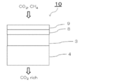
- FIG. 1 An example of the gas separation membrane 10 of the present invention shown in FIG. 1 is a thin-layer composite membrane, and has a support 4, a first separation layer 3, and a second separation layer 8 in this order. This is the separation membrane 10.
- FIG. 2 Another example of the gas separation membrane 10 of the present invention shown in FIG. 2 is a gas separation having a support 4, a first separation layer 3, a second separation layer 8, and a protective layer 9 in this order. It is the membrane 10.
- “on the support” means that another layer may be interposed between the support and the layer having separation selectivity.
- the direction in which the gas to be separated is supplied is “up” and the direction in which the separated gas is emitted is “down” as shown in FIG. .
- the second separation layer may be arranged in the order of the second separation layer and the first separation layer from the gas supply side.
- the protective layer 9 is in direct contact with the separation layer, and the protective layer is arranged in the order of the protective layer and the second separation layer from the gas supply side. Is preferred.
- the gas separation membrane of the present invention preferably further has a support on the side opposite to the protective layer of the first separation layer (the side opposite to the side in contact with the protective layer), and the first separation layer is the support. More preferably it is formed on top.
- the support is preferably a thin and porous material in order to ensure sufficient gas permeability.
- the first separation layer 3 may be formed or disposed on the surface or inner surface of the porous support, and by forming it on the surface, a thin-layer composite membrane can be easily formed. be able to.
- a gas separation membrane having the advantages of having both high gas separation selectivity, high gas permeability and high mechanical strength is obtained. Can do.
- the gas separation membrane of the present invention is a thin-layer composite membrane
- the thin-layer composite membrane is coated with the coating liquid (dope) forming the first separation layer 3 on the surface of the porous support (this specification)
- the term “coating” means to include an aspect of being attached to the surface by dipping).
- a resin layer may be formed on a porous support, and a first selective layer may be formed on the resin layer.
- the support preferably has a porous layer (Porous Layer) on the first separation layer 3 side, and a porous layer and a nonwoven fabric (Non-Woven) arranged on the first separation layer 3 side. ) Is more preferable.
- the porous layer preferably applied to the support is not particularly limited as long as it has the purpose of meeting high mechanical strength and high gas permeability.
- an organic polymer porous film is preferable.
- the thickness of the porous layer is usually 1 to 3000 ⁇ m, preferably 5 to 500 ⁇ m, more preferably 5 to 150 ⁇ m.
- the porous structure of this porous layer usually has an average pore diameter of 10 ⁇ m or less, preferably 0.5 ⁇ m or less, more preferably 0.2 ⁇ m or less, and a porosity of preferably 20 to 90%. Preferably, it is 30 to 80%.
- the molecular weight cutoff of the porous layer is preferably 100,000 or less, and the gas permeability is 3 ⁇ 10 ⁇ 5 cm 3 (STP; STP is an abbreviation for Standard Temperature and Pressure). ) / Cm 2 ⁇ cm ⁇ sec ⁇ cmHg (30 GPU; GPU is an abbreviation for Gas Permeation Unit).
- the material for the porous layer include conventionally known polymers such as polyolefin resins such as polyethylene and polypropylene, fluorine-containing resins such as polytetrafluoroethylene, polyvinyl fluoride, and polyvinylidene fluoride, polystyrene, cellulose acetate, and polyurethane.
- the shape of the porous layer can be any shape such as a flat plate type, a spiral type, a tube type, and a hollow fiber type.
- a woven fabric, a nonwoven fabric, a net or the like is preferably provided in order to impart mechanical strength to the lower portion of the porous layer disposed on the first separation layer 3 side.
- Nonwoven fabrics are preferably used from the viewpoint of cost.
- the nonwoven fabric fibers made of polyester, polypropylene, polyacrylonitrile, polyethylene, polyamide or the like may be used alone or in combination.
- the nonwoven fabric can be produced, for example, by making a main fiber and a binder fiber uniformly dispersed in water using a circular net or a long net, and drying with a dryer.
- the gas separation membrane of the present invention includes a first separation layer,
- the first separation layer is a ratio of the number of silicon atoms to the number of carbon atoms at the interface of the first separation layer on the second separation layer side (interface on the side in contact with the second separation layer). The ratio is 0.3 or less.
- the thickness of the first separation layer is preferably a thin film as much as possible under the condition of imparting high gas permeability while maintaining mechanical strength and gas separation selectivity. From the viewpoint of enhancing gas permeability, the first separation layer is preferably a thin layer.
- the thickness of the first separation layer is preferably 3 ⁇ m or less, more preferably 1 ⁇ m or less, particularly preferably 200 nm or less, and particularly preferably 100 nm or less.
- the thickness of the first separation layer is usually 10 nm or more, and is practically preferably 30 nm or more, more preferably 50 nm or more from the viewpoint of film formation.
- the first separation layer has a Si / C ratio of 0.3 or less, which is a ratio of the number of silicon atoms to the number of carbon atoms at the interface of the first separation layer on the second separation layer side, and gas separation selection From the viewpoint of properties, it is preferably 0.2 or less, more preferably 0.1 or less, and particularly preferably 0.
- the layer can be specified and the interface can be specified by utilizing the difference in the atomic content (composition ratio) of any of the atoms constituting each layer.
- the interface between the two layers in contact with each other was prepared by measuring the composition in the thickness direction by ESCA and etching, and making the horizontal axis the length in the layer thickness direction and the vertical axis the atomic content of any atom. In this case, the midpoint of the length in the thickness direction of the layer in the region where the inclination of the graph exists.
- the atoms to be noted when specifying the layer and specifying the interface between the two layers are the priorities of fluorine atom, carbon atom, oxygen atom and nitrogen atom. First, focusing on atoms with high priority, the layer is specified and the interface between the two layers is specified.
- the first separation layer preferably contains a resin.
- the resin for the first separation layer include, but are not limited to, the following. Specifically, polyimide, polyamides, celluloses, polyethylene glycols, and polybenzoxazoles are preferable.
- the resin of the first separation layer is preferably celluloses or polyimide.
- the resin of the first separation layer is more preferably polyimide.
- the polyimide is preferably a polyimide having a reactive group.
- the resin of the first separation layer is preferably a polyimide containing a sulfonamide group.
- the resin of the first separation layer is a polyimide having a reactive group
- the resin of the first separation layer is a polyimide having a reactive group
- the polyimide having a reactive group is a polymer having a reactive group, a polyimide unit and a reactive group (preferably a nucleophilic reactive group in the side chain, more preferably a carboxyl group, an amino group).
- the polymer having a reactive group is a polyimide described in ⁇ 0040> to ⁇ 0068> of JP-A-2015-160201, or a repeating unit represented by the following formula (I): It is preferable that it is a polyimide containing at least.
- the resin of the first separation layer is more preferably a polyimide containing at least a repeating unit represented by the following formula (I), particularly preferably a polyimide containing a sulfonamide group. .
- R I represents a hydrogen atom, an alkyl group, or a halogen atom.
- X a represents a polar group selected from a sulfonamide group, an alkoxysulfonyl group, a carboxyl group, a hydroxyl group, an acyloxy group, and a halogen atom.
- R represents a group having a structure represented by any one of the following formulas (I-1) to (I-28).
- X 1 to X 3 represent a single bond or a divalent linking group
- L represents —CH ⁇ CH— or —CH 2 —
- R 1 and R 2 represent a hydrogen atom or a substituent
- * represents a formula ( The bonding site
- R is preferably a group represented by the formula (I-1), (I-2) or (I-4), and is a group represented by (I-1) or (I-4). Is more preferable, and a group represented by (I-1) is particularly preferable.
- X 1 to X 3 represent a single bond or a divalent linking group.
- the divalent linking group —C (R x ) 2 — (R x represents a hydrogen atom or a substituent. When R x is a substituent, they may be linked to each other to form a ring), —O—, —SO 2 —, —C ( ⁇ O) —, —S—, —NR Y — (R Y is a hydrogen atom, an alkyl group (preferably a methyl group or an ethyl group) or an aryl group (preferably phenyl).
- R x represents a substituent
- specific examples thereof include groups selected from the substituent group Z described in ⁇ 0055> to ⁇ 0060> of JP-A-2015-160201.
- an alkyl group preferably The range is preferably the same as the alkyl group shown in the substituent group Z described in ⁇ 0055> to ⁇ 0060> of JP-A-2015-160201
- Trifluoromethyl is particularly preferred.
- X 3 is either one of the two carbon atoms described on the left side of X 3 (left side of the paper; the same applies to the left and right sides) and the right side of X 3 It is connected to one of the two carbon atoms described in the above.
- L represents —CH ⁇ CH— or —CH 2. -Is shown.
- the plurality of L in (I-23) may be the same or different.
- R 1 and R 2 represent a hydrogen atom or a substituent.
- substituents include groups selected from the substituent group Z described in ⁇ 0055> to ⁇ 0060> of JP-A-2015-160201.
- R 1 and R 2 may be bonded to each other to form a ring.
- R 1 and R 2 are preferably a hydrogen atom or an alkyl group, more preferably a hydrogen atom, a methyl group or an ethyl group, and even more preferably a hydrogen atom.
- a substituent may be added to the carbon atom shown in the formulas (I-1) to (I-28).
- Specific examples of this substituent include groups selected from the substituent group Z described in ⁇ 0055> to ⁇ 0060> of JP-A-2015-160201, and among them, an alkyl group or an aryl group is preferable.
- R I represents a hydrogen atom, an alkyl group or a halogen atom.
- This alkyl group may be linear or branched.
- the alkyl group that can be taken as R I preferably has 1 to 5 carbon atoms, more preferably 1 to 3 carbon atoms, and still more preferably 1 or 2.
- the alkyl group which can be taken as R I may have a hetero atom (preferably an oxygen atom or a sulfur atom) in the chain.
- R I are mentioned a methyl group or an ethyl group, more preferably a methyl group.
- R I examples include a bromine atom, a chlorine atom, an iodine atom, and a fluorine atom, and a bromine atom is more preferable.
- R I is more preferably a hydrogen atom, a methyl group or a bromine atom, still more preferably a hydrogen atom or a methyl group, still more preferably a hydrogen atom.
- X a is a sulfonamide group, alkoxysulfonyl group, a carboxyl group, a hydroxyl group, the polar group selected from an acyloxy group and a halogen atom.
- the sulfonamide group that can be adopted as X a may be unsubstituted or may have a substituent.
- the sulfonamide group that can be taken as X a is preferably unsubstituted, monoalkyl-substituted or dialkyl-substituted, unsubstituted, or more preferably monoalkyl-substituted, It is particularly preferred that it is unsubstituted.
- the substituent is preferably an alkyl group.
- the alkyl group may be linear or branched, and the carbon number thereof is preferably 1 to 10, more preferably 1 to 5, and more preferably 1 to 3.
- the alkyl group preferably has a halogen atom as a substituent, and more preferably has a fluorine atom as a substituent.
- Preferable specific examples of the alkyl group that the sulfonamide group has include methyl group, ethyl group, n-propyl group, —CH 2 CF 2 CF 2 CF 3 , —CH 2 CF 2 CF 3, and —CH 2 CF 3.
- this alkyl group is preferably a methyl group or an alkyl group having a fluorine atom as a substituent, more preferably a methyl group, —CH 2 CF 2 CF 2 CF 3 or —CH 2 CF 3 .
- this alkyl group is preferably a methyl group.
- sulfonamide group which can be taken as X a preferably contains a cycloalkyl group as a substituent.
- the cycloalkyl group preferably has 3 to 15 carbon atoms, and more preferably 6 to 10 carbon atoms. Of these, the cycloalkyl group is preferably an adamantyl group.
- the number of the cycloalkyl groups that the sulfonamide group has is preferably one. That is, the sulfonamide group is preferably a mono-substituted product.
- the sulfonamide group that can be taken as X a is unsubstituted.
- the alkoxysulfonyl group that can be taken as X a preferably has 1 to 5 carbon atoms, and more preferably 1 to 3 carbon atoms.
- the alkoxy group in the alkoxysulfonyl group that can be taken as X a is preferably a methoxy group or an ethoxy group, and more preferably a methoxy group.
- Acyloxy group which may take as X a are preferably the number of carbon atoms thereof is 2 to 5, more preferably 2 or 3, among which acetoxy group is particularly preferable.
- halogen atom examples include a bromine atom, a chlorine atom, an iodine atom, and a fluorine atom, and a bromine atom is preferable.
- X a is preferably a sulfonamido group, an alkoxysulfonyl group, a carboxyl group, a hydroxyl group and an acyloxy group, more preferably a sulfonamido group, an alkoxysulfonyl group, a carboxyl group and a hydroxyl group, particularly preferably a sulfonamido group and a carboxyl group. And a hydroxyl group, more preferably a sulfonamide group.
- the repeating unit represented by formula (I) has three CR I 3 in the diamine component, flatness or packing of polyimide is moderately suppressed, the free volume fraction It is estimated that the gas permeability is improved.
- the repeating unit represented by the formula (I) has a specific polar group as Xa, the polyimide is appropriately densified and its mobility is lowered. It is estimated that the permeability can be effectively suppressed and the gas separation selectivity can be further improved.
- the polyimide having the repeating unit of the above formula (I) has a diamine component having three CR I 3 groups.
- the polyimide which has many alkyl groups has low polarity, there exists a tendency for affinity with low polarity impurities, such as toluene, to increase, and to be inferior to plasticization tolerance.
- polyimide having recurring units of the formula (I) is in the diamine component, with a particular site specific polar group X a in addition to the three CR I 3 groups.
- a gas separation membrane exhibiting high gas permeability and gas separation selectivity, and having a polar group that suppresses affinity with impurities and has excellent plasticization resistance can be produced. .
- the polyimide may be in a form crosslinked with a crosslinking agent.
- a crosslinking agent such as tetraisopropyl orthotitanate
- a metal alkoxide such as tetraisopropyl orthotitanate
- it can be used as an agent.
- the CR I 3 has a halogen atom, for the purpose of nucleophilic addition reaction, it can be used cross-linking agents such as dimethyl amino propyl triethoxy silane and tetramethylethylenediamine.
- the polyimide used in the present invention contains a repeating unit represented by the formula (II-a) or (II-b) described later, the polyimide has a group capable of reacting with a functional group contained in these repeating units. It may be in a form crosslinked with a crosslinking agent.
- the repeating unit represented by the above formula (I) is preferably a repeating unit represented by the following formula (Ia).
- R and X a have the same meanings as R and X a in formula (I), respectively, and preferred forms are also the same.
- the repeating unit represented by the above formula (Ia) is preferably a repeating unit represented by the following formula (Ib).
- R has the same meaning as R in the formula (Ia), and preferred forms are also the same.
- R II represents a hydrogen atom or a substituent. Of the two R II s , at least one R II is preferably a hydrogen atom, more preferably two R IIs are both hydrogen atoms.
- R II is a substituent, a group selected from the substituent group Z described in ⁇ 0055> to ⁇ 0060> of JP-A-2015-160201 is preferable, and an alkyl group or a cycloalkyl group is more preferable.
- the alkyl group that can be taken as R II may be linear or branched, and the carbon number thereof is preferably 1 to 10, more preferably 1 to 5, and particularly preferably 1 to 3.
- the alkyl group preferably has a halogen atom as a substituent, and more preferably has a fluorine atom as a substituent.
- R II is an alkyl group
- R II is an alkyl group
- the alkyl group is preferably a methyl group or an alkyl group having a fluorine atom as a substituent, more preferably a methyl group.
- the alkyl group is preferably a methyl group.
- the cycloalkyl group that can be employed as R II preferably has 3 to 15 carbon atoms, and more preferably 6 to 10 carbon atoms.
- R II is a cycloalkyl group, it is preferably an adamantyl group.
- one of the two R II is a cycloalkyl group, the other is preferably a hydrogen atom.
- the repeating unit represented by the above formula (Ib) is preferably a repeating unit represented by the following formula (Ic).
- R has the same meaning as R in the formula (Ib), and preferred forms are also the same.
- the polyimide used in the present invention may have a repeating unit represented by the following formula (II-a) or (II-b) in addition to the repeating unit represented by the above formula (I).
- R has the same meaning as R in formula (I), and the preferred range is also the same.
- R 4 to R 6 represent a substituent. Examples of the substituent include groups selected from the substituent group Z described in ⁇ 0055> to ⁇ 0060> of JP-A-2015-160201.
- R 4 is preferably an alkyl group, a carboxyl group, or a halogen atom.
- L1 indicating the number of R 4 is an integer of 0 to 4.
- R 4 is an alkyl group, preferably l1 is 1-4, more preferably 2-4, particularly preferably 3 or 4.
- R 4 is a carboxyl group, l1 is preferably 1 to 2, more preferably 1.
- R 4 is an alkyl group
- the alkyl group preferably has 1 to 10 carbon atoms, more preferably 1 to 5 carbon atoms, and particularly preferably 1 to 3 carbon atoms.
- R 4 is an alkyl group, it is particularly preferably a methyl group, an ethyl group or a trifluoromethyl group.
- the two linking sites are preferably located at the meta position or the para position relative to each other. It is more preferable that it is located in.
- the structure represented by the formula (II-a) does not include the structure represented by the formula (I).
- R 5 and R 6 preferably represent an alkyl group or a halogen atom, or represent a group which forms a ring together with X 4 by being linked to each other. Further, a form in which two R 5 are connected to form a ring and a form in which two R 6 are connected to form a ring are also preferred.
- the structure in which R 5 and R 6 are linked is not particularly limited, but a single bond, —O— or —S— is preferable.
- M1 and n1 representing the number of R 5 and R 6 are integers of 0 to 4, preferably 1 to 4, more preferably 2 to 4, particularly preferably 3 or 4.
- the alkyl group preferably has 1 to 10 carbon atoms, more preferably 1 to 5 carbon atoms, and particularly preferably 1 to 3 carbon atoms.
- R 5 and R 6 are alkyl groups, a methyl group, an ethyl group, or a trifluoromethyl group is particularly preferable.
- X 4 has the same meaning as X 1 in formula (I-1), and the preferred range is also the same.
- the repeating unit represented by the above formula (I), the repeating unit represented by the above formula (II-a), and the repeating unit represented by the above formula (II-b) are combined.
- the proportion of the molar amount of the repeating unit represented by the formula (I) in the molar amount is preferably 50 to 100 mol%, more preferably 70 to 100 mol%, particularly preferably 80 to 100 mol%. 90 to 100 mol% is more particularly preferable.
- the repeating unit represented by the above formula (I), the repeating unit represented by the above formula (II-a), and the repeating unit represented by the above formula (II-b) account for the total molar amount.
- the ratio of the molar amount of the repeating unit represented by the formula (I) is 100 mol% means that the polyimide has a repeating unit represented by the above formula (II-a) and the above formula (II-b). Means that none of the repeating units represented by
- the polyimide consists of a repeating unit represented by the above formula (I) or may have a repeating unit other than the repeating unit represented by the above formula (I).
- the remainder other than the repeating unit represented by the above formula (I) is the above formula (II-a) or the above formula (II- It is preferable to consist of the repeating unit represented by b).
- repeating unit represented by the above formula (II-a) or (II-b) means an embodiment comprising the repeating unit represented by the above formula (II-a), the above formula 3 of an embodiment comprising a repeating unit represented by (II-b) and an embodiment comprising a repeating unit represented by the above formula (II-a) and a repeating unit represented by the above formula (II-b) It is meant to include one embodiment.
- the gas separation membrane of the present invention has a structure in which the resin of the first separation layer is derived from 4,4 ′-(hexafluoroisopropylidene) diphthalic anhydride (6FDA) from the viewpoint of separation selectivity and gas permeability. It is preferable that it is a polyimide containing. That is, the mother nucleus R is a group represented by the formula (I-1), X 1 is preferably —C (R x ) 2 —, and R x is preferably trifluoromethyl.
- R is a group represented by the formula (I-1)
- X 1 is preferably —C (R x ) 2 —
- R x is preferably trifluoromethyl.
- the substituent group Z described in ⁇ 0055> to ⁇ 0060> of JP-A-2015-160201 may be further substituted with any one or more substituents selected from the substituent group Z.
- substituents selected from the substituent group Z when one structural site has a plurality of substituents, these substituents are connected to each other to form a ring, or condensed with a part or all of the above structural sites to form an aromatic group.
- a ring or an unsaturated heterocyclic ring may be formed.
- a compound or a substituent when a compound or a substituent includes an alkyl group, an alkenyl group, etc., these may be linear or branched, and may be substituted or unsubstituted. When an aryl group, a heterocyclic group, or the like is included, they may be monocyclic or condensed, and may be substituted or unsubstituted.
- substituent group Z when only the names of the respective groups are described (for example, when only “alkyl group” is described), preferred ranges and / or specifics of the corresponding groups in the substituent group Z are described. Examples apply.
- the molecular weight of the polyimide that can be used in the present invention is preferably 10,000 to 1,000,000 as a weight average molecular weight, more preferably 15,000 to 500,000, and still more preferably 20,000. ⁇ 200,000.
- the molecular weight and the degree of dispersion are values measured using a gel permeation chromatography (GPC) method, and the molecular weight is a weight average molecular weight in terms of polystyrene.
- the gel packed in the column used in the GPC method is preferably a gel having an aromatic compound as a repeating unit, and examples thereof include a gel made of a styrene-divinylbenzene copolymer. Two to six columns are preferably connected and used.
- the solvent used include ether solvents such as tetrahydrofuran and amide solvents such as N-methylpyrrolidinone.
- the measurement is preferably performed at a solvent flow rate in the range of 0.1 to 2 mL / min, and most preferably in the range of 0.5 to 1.5 mL / min. By performing the measurement within this range, the apparatus is not loaded and the measurement can be performed more efficiently.
- the measurement temperature is preferably 10 to 50 ° C., more preferably 20 to 40 ° C.
- the column and solvent to be used can be suitably selected according to the physical property of the high molecular compound used as measurement symmetry.
- the polyimide having a reactive group that can be used in the present invention can be synthesized by condensation polymerization of a specific bifunctional acid anhydride (tetracarboxylic dianhydride) and a specific diamine.
- tetracarboxylic dianhydride tetracarboxylic dianhydride
- a specific diamine tetracarboxylic dianhydride
- it is a general book (eg, Ikuo Imai, edited by Rikio Yokota, “Latest Polyimide: Fundamentals and Applications”, published by NTS Inc., August 25, 2010, pages 3-49. Etc.) can be appropriately selected.
- At least one tetracarboxylic dianhydride as one raw material is represented by the following formula (IV). It is more preferable that all tetracarboxylic dianhydrides used as raw materials are represented by the following formula (IV).
- R has the same meaning as R in the formula (I).
- tetracarboxylic dianhydrides that can be used in the present invention include the following.
- At least one diamine compound as the other raw material is represented by the following formula (V).
- R I and X a have the same meanings as R I and X a in formula (I), respectively.
- diamine compound represented by the formula (V) examples include, for example, those shown below, but the present invention is not limited thereto.
- Me means methyl and Et means ethyl.
- R 4 and l1 are each synonymous with R 4 and l1 in the above formula (II-a).
- the diamine compound represented by the formula (VII-a) does not include the diamine compound represented by the formula (V).
- R 5 , R 6, X 4, m1 and n1 are the same meanings as R 5, R 6, X 4 , m1 and n1 in the formula (II-b).
- the monomer represented by the above formula (IV) and the monomer represented by the above formula (V), (VII-a) or (VII-b) may be used in advance as an oligomer or a prepolymer.
- the polyimide used in the present invention may be any of a block copolymer, a random copolymer, and a graft copolymer.
- polyimide (P-02) used in Examples described later can be preferably used.
- the copolymerization ratio (molar ratio) x is 20 in the exemplified polyimide P-100 of ⁇ 0068> of JP-A-2015-160201.
- polyimide (P-101) in which y is 80 can be preferably used.
- the resin of the separation layer is polyimide
- P84 or P84HT sold by P84HT is also preferable.
- celluloses such as cellulose acetate, cellulose triacetate, cellulose acetate butyrate, cellulose propionate, ethyl cellulose, methyl cellulose, and nitrocellulose can be selected.
- the substitution degree of all acyl groups is preferably 2.0 to 2.7.
- Cellulose acetate commercially available as cellulose acetate L-40 (acyl group substitution degree 2.5, manufactured by Daicel Corporation) can also be preferably used.
- polyethylene glycols such as polymerized polymer of polyethylene glycol # 200 diacrylate (manufactured by Shin-Nakamura Chemical Co., Ltd.), polymers described in JP-T-2010-513021, and the like should be selected. Can do.
- the gas separation membrane of the present invention includes a second separation layer, and the second separation layer has a maximum F / C ratio that is a ratio of the number of fluorine atoms to the number of carbon atoms of 0.20 or more. And the Si / C ratio in the part where F / C ratio takes the maximum value is 0.3 or less.
- the thickness of the second separation layer is preferably a thin film as much as possible under the conditions of imparting mechanical strength, gas separation selectivity, and gas permeability.
- the thickness of the second separation layer is preferably 20 to 200 nm, more preferably 20 to 150 nm, and particularly preferably 30 to 100 nm.
- the second separation layer may be a single layer or two or more layers.
- the gas separation membrane preferably has 1 to 5 second separation layers, more preferably 1 to 3 layers, particularly preferably 1 to 2 layers from the viewpoint of production cost, and is preferably a single layer. More particularly preferred.
- the second separation layer may be formed by laminating two or more identical layers or two or more different layers.
- the maximum value of the F / C ratio which is the ratio of the number of fluorine atoms to the number of carbon atoms, is 0.20 or more, and from the viewpoint of suppressing a decrease in gas separation selectivity after exposure to an impurity gas. 0.2 to 2 is preferable, and 0.25 to 1.6 is particularly preferable.
- the second separation layer has an Si / C ratio of 0.3 or less at a portion where the F / C ratio takes a maximum value, and is preferably 0.2 or less from the viewpoint of gas separation selectivity. It is more preferably 1 or less, and particularly preferably 0.
- the free volume diameter of the second separation layer is preferably 0.6 nm or more, more preferably 0.6 to 0.86 nm, and 0.6 to 0.74 nm. It is particularly preferred.
- the free volume diameter of the second separation layer is obtained from ⁇ 3 obtained by the positron annihilation method, and the free volume diameter of the second separation layer (the diameter of the holes in the second separation layer) is expressed by a semi-empirical formula: T.A. Tao, J.A. Chem. Phys. , 56, 5499 (1972)).
- the positron annihilation method is a method that utilizes the fact that positrons are extremely small and evaluates pores (free volume holes) having a diameter of about 1 to 10 nm, which is difficult to measure by other methods.
- the hole diameter of a layer containing a polymer compound such as a polymer is determined by analyzing the third component, which is a long-lived component of the positron lifetime spectrum, and measuring the positron lifetime ⁇ 3 of the third component (o-Ps). And can be calculated.
- Positrons combine with electrons in the polymer to form ortho-positronium o-Ps. This o-Ps is considered to be trapped in the vacancies and disappear.
- the lifetime ⁇ 3 of o-Ps at that time is expressed as a function of the radius R of the holes.
- the analysis of the positron lifetime can be performed using the nonlinear least square program POSITRONFIT.
- the relative intensity I3 of the third component representing the porosity of the holes is also calculated.
- a positron beam device using an electron linear accelerator it is possible to change the positron implantation energy, and it is possible to obtain information on the surface vacancies at a lower energy and at a higher energy. With an implantation energy of 1 keV, information of about 20 nm mainly from the surface in the depth direction can be obtained.
- the positron lifetime ⁇ 3 of the third component when a positron is injected from the surface of the second separation layer with an intensity of 1 keV is, for example, 2.14 ns or more
- the depth direction from the surface of the second separation layer (support In the direction) when averaged to about 20 nm, it is expected that pores having a pore diameter of 0.6 nm or more exist.
- the presence of such pores in the depth direction (support direction) from the surface of the second separation layer at about 20 nm allows the second separation layer to be moderate in the separation of CO 2 and CH 4. Therefore, both gas permeability and gas separation selectivity can be increased.
- the second separation layer is preferably crosslinked from the viewpoint of abrasion resistance. Cross-linking can be confirmed by, for example, insolubilization in an organic solvent.
- the second separation layer is insoluble in an organic solvent composed of toluene and heptane having a mass ratio of 1: 1.
- the second separation layer may be a sol-gel cured product obtained by hydrolysis and polycondensation. In this case, the sol-gel reaction is preferably initiated or accelerated based on photoexcitation.
- the second separation layer preferably contains a resin.
- a fluorine atom-containing resin is preferably included. Note that the resin of the second separation layer may contain other resins.
- fluorine atom containing resin used as resin of a 2nd separated layer.
- a fluororesin is a generic term for plastics containing fluorine atoms in the molecule. For example, if a fluorine atom enters an acrylic resin, it becomes a fluorine-containing acrylic resin and is one of the fluororesins. Furthermore, a copolymer of a resin containing a fluorine atom and a resin not containing a fluororesin is one of the fluororesins because the molecule contains a fluorine atom. Thus, there is a very wide range of fluororesins.
- the resin for the second separation layer for example, a fluorine-containing polyimide described in JP-A-8-052332, a perfluoro resin (perfluorocyclopolymer) containing a heterocyclic structure in the main chain, a polymer of fluoro (meth) acrylate And polymers of fluoroolefins.
- the gas separation membrane of the present invention preferably contains at least one of a fluoro (meth) acrylate polymer and a fluoroolefin polymer as a resin for the second separation layer.
- fluoro (meth) acrylate polymer examples include those obtained by polymerizing a composition containing fluoro (meth) acrylate, which is an example of a monomer having a fluorine atom described below. Moreover, you may use the polymer of a commercially available fluoro (meth) acrylate as it is.
- fluoro (meth) acrylate polymers examples include fluorine-containing acrylic acid derivative polymers described in ⁇ 0014> to ⁇ 0022> of JP-A-60-118217. Embedded in the book.
- fluoroolefin polymer examples include a homopolymer or copolymer of fluoroolefin and an alternating copolymer of fluoroolefin and vinyl ether.
- fluoroolefin homopolymer or copolymer examples include a tetrafluoroethylene resin or an oligomer thereof, and a tetrafluoroethylene-6fluoropropylene copolymer resin.
- alternating copolymer of fluoroolefin and vinyl ether examples include a tetrafluoroethylene-fluorovinyl ether copolymer resin.
- fluoroolefin polymer examples include compounds described in ⁇ 0011> of JP-A-5-329343 and compounds described in ⁇ 0016> to ⁇ 0025> of JP-T-2016-503448. The contents of this publication are incorporated herein.
- fluorine atom-containing resin A commercially available product may be used as the fluorine atom-containing resin.
- Commercially available fluorine atom-containing resins include, for example, Asahi Glass Cytop series (Cytop CTL809M used in the examples described later), Asahi Glass Lumiflon series, Arkema Kynar series, DIC Fluoronate series (described below) Fonate K-704 used in the examples), MEGAFACE series manufactured by DIC, DEFENSA OP series manufactured by DIC, and Nafion series manufactured by Sigma-Aldrich.
- -Other resins other than fluorine atom-containing resins examples include resins obtained by polymerizing and / or crosslinking other monomers other than halogen atom-containing monomers. Other monomers other than the halogen atom-containing monomer will be described later.
- the second separation layer is preferably cross-linked.
- the resin used for the second separation layer described so far may be used as the resin precursor, and a resin obtained by crosslinking the resin precursor may be used as the resin for the second separation layer.
- the resin of the second separation layer preferably contains at least one of an acrylate bond, a methacrylate bond, a urethane bond, and an ether bond.
- the acrylic ester bond and the methacrylic ester bond are preferably a structure in which a fluoro (meth) acrylate monomer described below is polymerized and / or a structure in which a silicone acrylate monomer described below is polymerized.
- crosslinked is preferable.
- the ether bond is preferably a bond between a polyhydric alcohol-derived group contained in the molecule of a fluoro (meth) acrylate monomer described later and a (meth) acryloyl group.
- Examples of the monomer used for the second separation layer include a monomer having a fluorine atom and other monomers.
- -Monomers with fluorine atoms examples include F-modified dimethylsiloxane monomer, fluoroacrylate, fluoroepoxy monomer, fluoroolefin monomer, and fluoro (meth) acrylate. Of these, fluoro (meth) acrylate is preferred. Specifically, a (meth) acrylate compound containing a fluorine atom-containing hydrocarbon group described in ⁇ 0019> to ⁇ 0026> of JP-A-2014-105271, ⁇ 0047>-of JP-A 2012-99638, The compounds described in ⁇ 0060> and ⁇ 0126> can be used. The contents of these publications are incorporated herein by reference.
- the (meth) acrylate containing a fluorine atom-containing hydrocarbon group is preferably a compound represented by the following formula (1) or the following formula (2).
- C p F q- in the formulas (1) and (2) means a hydrocarbon group containing one or more fluorine atoms, and a straight chain, branched chain, or cyclic hydrocarbon group as long as it has one or more fluorine atoms These may be either saturated or unsaturated hydrocarbon groups. Of these, a linear or branched fluoroalkyl group, fluoroalkenyl group and fluorocycloalkyl group are preferred.
- p is preferably 2 to 18, more preferably 2 to 12, and still more preferably 1 to 10.
- Examples thereof include a perfluoromethyl group, a difluoroethyl group, a perfluoroethyl group, a pentafluoropropyl group, a perfluoropropyl group, a perfluorooctyl group, a perfluorononyl group, a perfluorocyclopentyl group, and a perfluorocyclohexyl group.
- the following groups are also preferable (in the formula, * represents a bond).
- a perfluoro group in which all hydrogen atoms of the hydrocarbon are substituted with fluorine atoms is preferable.
- Examples of the polyhydric alcohol used in A in the formulas (1) and (2) include pentaerythritol, dipentaerythritol, tripentaerythritol, glycerin, diglycerin, triglycerin, polyglycerin, sorbitol, mannitol, trimethylolpropane.
- Ditrimethylolpropane trimethylolethane, ditrimethylolethane, bis (dipentaethristol) adipate, tris (2-hydroxyethyl) isocyanurate; and alkylenes of these polyhydric alcohols (for example, ethylene, propylene, butylene, etc.) ) Oxide adducts; ⁇ -caprolactone modified products of these polyhydric alcohols.
- the dehydroxylated residue refers to a group obtained by removing a hydrogen atom from a hydroxyl group of a polyhydric alcohol.
- Examples of the (meth) acrylate containing a fluorine atom-containing hydrocarbon group include compounds represented by the following formula (1-1).
- p, q and R are as defined above, and n represents an integer of 1 to 5, preferably an integer of 1 to 3, more preferably 1 or 2.
- the compound represented by the formula (1-1) includes a compound of the following formula (1-2). (In the formula (1-2), p, q and R are as defined above.)
- the (meth) acrylate containing a fluorine atom-containing hydrocarbon group is preferably bifunctional to hexafunctional, more preferably bifunctional or trifunctional, and particularly preferably trifunctional.
- the functional number of the (meth) acrylate containing a fluorine atom-containing hydrocarbon group means the number of —O—CO—CR ⁇ CH 2 in one molecule.
- Examples of the (meth) acrylate containing a fluorine atom-containing hydrocarbon group include triacryloyl pentafluoroethyl pentaerythritol, triacryloyl heptafluoroisopropyl pentaerythritol, triacryloyl heptadecafluorononenyl pentaerythritol, pentaacryloyl pentafluoroethyldithiol.
- Examples include pentaerythritol, pentaacryloyl heptafluoroisopropyldipentaerythritol, pentaacryloyl heptadecafluorononenyl dipentaerythritol, and the like. Furthermore, the compounds described in JP-A-2003-313242 are listed.
- monomer having a fluorine atom examples include the following compounds.
- the present invention is not limited by the following specific examples.
- LINC-3A manufactured by Kyoeisha Chemical Co., Ltd.:
- fluorine-containing surfactant-- A fluorine-containing surfactant may be used as the monomer having a fluorine atom.
- the second separation layer preferably contains a fluorine-containing surfactant.
- a known surfactant can be used as the fluorine-containing surfactant.
- the fluorine-containing surfactant having an ultraviolet reactive group include the compounds described in ⁇ 0022> to ⁇ 0025> of JP-A-2016-11365, the contents of which are incorporated herein. It is.
- a commercially available product may be used as the fluorine-containing surfactant.
- Examples of commercially available fluorine-containing surfactants include Megafac RS-75 (manufactured by DIC, fluorine-containing group, hydrophilic group, lipophilic group and ultraviolet-reactive group-containing oligomer).
- -Other monomers other than monomers having fluorine atoms You may use other monomers other than the monomer which has a fluorine atom. Examples of other monomers other than the monomer having a fluorine atom include silicone acrylate monomers. Silicone acrylate monomers include Silaplane (registered trademark) FM-0611, Silaplane FM-0621, Silaplane FM-0625, and both-end (meth) acrylic Silaplane FM- from JNC Corporation.
- silaplane FM-7721, silaplane FM-7725, etc. silaplane FM-0411, silaplane FM-0421, silaplane FM-0428, silaplane FM-DA11, silaplane FM-DA21, silaplane-DA25, One-end type (meth) acrylic silaplane FM-0711, silaplane FM-0721, silaplane FM-0725, silaplane TM-0701, silaplane TM-0701T, and the like are available.
- the monomer which has a fluorine atom, and another monomer it is preferable to use together in the range with which a 2nd separated layer satisfy
- a monomer in combination of monomer having fluorine atom: other monomer 30 to 99.9: 0.1 to 70 (mass ratio).
- Monomer having fluorine atom: other monomer 50 to 99.9: It is more preferable to use the monomer in combination at 0.1 to 50 (mass ratio).
- photopolymerization initiator and radical polymerization initiator examples include the compounds described in ⁇ 0036> of JP2013-111565A, the contents of which are incorporated herein.
- Known photopolymerization initiators and radical polymerization initiators include, for example, benzoin ether, 2,2-dimethoxy-1,2-diphenylethane-1-one [IRGACURE651, manufactured by BASF Corporation, trademark], 1-hydroxy -Cyclohexyl-phenyl-ketone [IRGACURE184, manufactured by BASF Corp., trademark], 2-hydroxy-2-methyl-1-phenyl-propan-1-one [DAROCUR1173, manufactured by BASF Corp., trademark], 1- [ 4- (2-hydroxyethoxy) -phenyl] -2-hydroxy-2-methyl-1-propan-1-one [IRGACURE2959, trade name, manufactured by BASF Corporation], 2-hydroxy-1- [4- [4 -(2-Hydroxy-2-methyl-propionyl) -benzyl] pheny
- the photopolymerization initiator and radical polymerization initiator also include a photoacid generator.
- isocyanates can be used, and isocyanurate group-containing polyisocyanates are preferable.
- isocyanates include the compounds described in ⁇ 0022> to ⁇ 0030> of JP-A No. 2015-113415, the contents of which are incorporated herein.
- known curing agents for example, “Duranate TPA-100”, “Duranate TKA-100”, “Duranate TLA-100” manufactured by Asahi Kasei Chemicals Corporation, “Sumidule N3300” manufactured by Sumika Bayer Urethane Co., Ltd.
- the solid content concentration of the polymerization initiator is preferably 25% by mass or less, more preferably 0.1 to 15% by mass with respect to the resin precursor (resin or monomer) used in the second separation layer. 1 to 10% by mass is particularly preferable.
- These polymerization initiators can be used alone or in combination of two or more.
- the second separation layer As a material for the second separation layer, it is preferable to use a solvent, a polymerization inhibitor, an acid (for example, acetic acid, etc.) and the like.
- the content ratio of the resin precursor and each additive in the second separation layer is not particularly limited, but for example, the following content ratio is preferable.
- the content ratio of the resin precursor in the second separation layer is 1 to 20%
- the content ratio of the solvent is 50 to 95%
- the content ratio of the polymerization inhibitor is 0.01% to 5%
- the acetic acid content mass ratio is preferably 0.1 to 5%.
- the material of the second separation layer is preferably prepared as a composition containing an organic solvent when forming the second separation layer.
- the second separation layer is formed by performing a polymerization reaction or a crosslinking reaction, it is preferably prepared as a composition for forming the second separation layer precursor.
- the composition for forming the second separation layer precursor is preferably prepared as a composition that can be reacted by a sol-gel method.
- the solvent used for forming the second separated layer is not particularly limited. For example, n-heptane, acetic acid, water, n-hexane, 2-butanone, methanol, ethanol, isopropyl alcohol, cyclohexanone, acetone, dimethyl Examples thereof include sulfoxide (DMSO).
- the gas separation membrane preferably further has a protective layer.
- the protective layer is preferably a layer disposed on the second separation layer. Unintentional contact between the second separation layer and other materials can be prevented during handling and use.
- the protective layer is preferably a separate layer from the second separation layer.
- a material of a protective layer there is no restriction
- a material used for the protective layer the same material as the resin contained in the resin layer can be used.
- the material used for the protective layer include silicone resin, polyimide, cellulose resin, and polyethylene oxide.
- the protective layer may contain the filler.
- the filler used for the protective layer for example, inorganic particles described in ⁇ 0020> to ⁇ 0027> of JP-A-2015-160201 can be preferably used. Incorporated.
- the protective layer preferably contains a compound having a siloxane bond.
- 50% by mass or more of the protective layer is preferably a compound having a siloxane bond, more preferably 90% by mass or more is a compound having a siloxane bond, and 99% by mass or more is a compound having a siloxane bond.
- the protective layer is composed of only a compound having a siloxane bond.
- the compound having a siloxane bond may be a compound having a repeating unit containing at least a silicon atom, an oxygen atom and a carbon atom.
- the compound having a siloxane bond may be a compound having a siloxane bond and having a repeating unit, and is preferably a compound having a polysiloxane unit. That is, the compound having a siloxane bond is preferably a silicone resin.
- silicone resin used for the protective layer examples include polydimethylsiloxane (hereinafter also referred to as PDMS), polydiphenylsiloxane (Polydiphenylsiloxane), polydi (trifluoropropyl) siloxane (Polydi (trifluoropropyl) siloxane), polymethyl (3, 3, 3-Trifluoropropyl) siloxane (including poly [methyl (3,3,3-trifluoropropyl) siloxane]) and poly (1-trimethylsilyl-1-propyne) (hereinafter also referred to as PTMSP) It is preferable.
- the silicone resin used for the protective layer preferably contains polydimethylsiloxane or poly (1-trimethylsilyl-1-propyne), and particularly preferably contains polydimethylsiloxane.
- Silicone resin such as PDMS used for the protective layer has high CO 2 gas permeability, but also has high permeability for impurities such as BTX, and suppresses plasticization of the first separation layer including polyimide with high separation selectivity. It wasn't done.
- Silicone resin such as PDMS used for the protective layer has a hardness as small as 0.7.
- defects can be significantly reduced in modular handling up to spiral rounding by making the second separation layer a hard film.
- a commercially available material can be used as the silicone resin used for the protective layer.
- silicone resin used for the protective layer For example, UV9300 (Momentive polydimethylsiloxane (PDMS)), X-22-162C (Shin-Etsu Chemical Co., Ltd.), etc. can be preferably used.
- the silicone resin used for the protective layer can be prepared as a composition containing an organic solvent when forming the protective layer, and is preferably a curable composition.
- the organic solvent that can be used when forming the protective layer containing a silicone resin is not particularly limited, and examples thereof include n-heptane.
- the thickness of the protective layer can be set to, for example, 50 to 4000 nm.
- the thickness of the protective layer is preferably 100 to 3200 nm from the viewpoint of achieving both abrasion resistance and gas permeability, and more preferably 100 to 1000 nm.
- the separation layer is thin (for example, 500 nm or less), it is easily affected by scratches.
- the gas separation membrane of the present invention is a thin layer composite membrane, it is preferable to have a resin layer between the first separation layer and the support from the viewpoint of improving adhesion.
- Resin layer is a layer containing resin.
- This resin preferably has a polymerizable functional group.
- functional groups include epoxy groups, oxetane groups, carboxyl groups, amino groups, hydroxyl groups, and thiol groups.
- the resin layer includes an epoxy group, an oxetane group, a carboxyl group, and a resin having two or more of these groups.
- Such a resin is preferably formed on the support by curing using radiation irradiation to the radiation curable composition.
- the polymerizable dialkylsiloxane is a monomer having a dialkylsiloxane group, a polymerizable oligomer having a dialkylsiloxane group, or a polymer having a dialkylsiloxane group.
- the resin layer may be formed from a partially crosslinked radiation curable composition having a dialkylsiloxane group.
- the dialkylsiloxane group include a group represented by — ⁇ O—Si (CH 3 ) 2 ⁇ n — (n is 1 to 100, for example).
- a poly (dialkylsiloxane) compound having a vinyl group at the terminal can also be preferably used.
- the material of the resin layer is preferably at least one selected from polydimethylsiloxane, poly (1-trimethylsilyl-1-propyne), and polyethylene oxide.
- Polydimethylsiloxane or poly (1-trimethylsilyl-1-propyne) Is more preferable, and polydimethylsiloxane is particularly preferable.
- UV9300 Momentive polydimethylsiloxane (PDMS)
- X-22-162C Shin-Etsu Chemical Co., Ltd.
- the material of the resin layer can be prepared as a composition containing an organic solvent when forming the resin layer, and is preferably a curable composition.
- the thickness of the resin layer is not particularly limited, but the thickness of the resin layer is preferably 20 to 1000 nm, more preferably 20 to 900 nm, and particularly preferably 30 to 800 nm.
- the thickness of the resin layer can be determined by a scanning electron microscope (SEM).
- the gas separation membrane of the present invention can be suitably used as a gas separation membrane used in a gas separation recovery method and a gas separation purification method.
- a gas separation membrane used in a gas separation recovery method and a gas separation purification method.
- a gas separation membrane capable of efficiently separating a specific gas from a gas mixture containing a gas such as a perfluoro compound.
- the gas separation membrane of the present invention is preferably a gas separation membrane for separating at least one kind of acidic gas from a gas mixture of acidic gas and non-acidic gas.
- the acid gas include carbon dioxide, hydrogen sulfide, carbonyl sulfide, sulfur oxide (SOx), and nitrogen oxide (NOx), and carbon dioxide, hydrogen sulfide, carbonyl sulfide, sulfur oxide (SOx), and nitrogen. It is preferably at least one selected from oxides (NOx), more preferably carbon dioxide, hydrogen sulfide or sulfur oxide (SOx), and particularly preferably carbon dioxide.
- the non-acidic gas is preferably at least one selected from hydrogen, methane, nitrogen, and carbon monoxide, more preferably methane and hydrogen, and particularly preferably methane.
- the gas separation membrane of the present invention even when higher-order hydrocarbon gas such as BTX (benzene, toluene, xylene) or propane, butane, hexane is included as the non-acid gas, at least from the gas mixture of the acid gas and the non-acid gas, One kind of acid gas can be separated.
- the gas separation membrane of the present invention is preferably a gas separation membrane that selectively separates carbon dioxide from a gas mixture containing carbon dioxide / hydrocarbon (especially methane).
- the gas separation membrane of the present invention is also preferably a gas separation membrane that selectively separates carbon dioxide from a gas mixture containing carbon dioxide / hydrocarbon (particularly methane) / higher hydrocarbons.
- the permeation rate of carbon dioxide at 30 ° C. and 5 MPa is preferably 10 GPU or more, more preferably 10 to 300 GPU. 15 to 300 GPU is particularly preferable.
- 1 GPU is 1 ⁇ 10 ⁇ 6 cm 3 (STP) / cm 2 ⁇ sec ⁇ cmHg.
- the gas separation membrane of the present invention is a gas separation selection which is the ratio of the carbon dioxide permeation flux to the methane permeation flux at 30 ° C. and 5 MPa when the gas to be separated is a mixed gas of carbon dioxide and methane.
- the property ⁇ is preferably 30 or more, more preferably 35 or more, particularly preferably 40 or more, and more preferably 50 or more.
- the manufacturing method of a gas separation membrane includes the process of forming a resin layer on a support body.
- a method of forming a resin layer on a support body It is preferable to apply
- the coating method is not particularly limited, and a known method can be used. For example, a spin coating method, a dip coating method, or a bar coating method can be appropriately used.
- the composition containing the resin layer material and the organic solvent is preferably a curable composition.
- Irradiation with an electron beam, ultraviolet (UV), visible light, or infrared light can be used, and radiation can be appropriately selected depending on the material to be used.
- the irradiation time is preferably 1 to 30 seconds.
- the radiant energy is preferably 10 to 500 mW / cm 2 .
- the plasma treatment be performed for 5 seconds or more under the above conditions from the viewpoint of enhancing the separation selectivity and increasing the abrasion resistance to make it difficult to lower the separation selectivity.
- plasma processing is 1000 second or less on said conditions.
- the integrated energy amount of the plasma treatment is preferably 25 to 500,000 J.
- the plasma treatment may be performed by a conventional method, and conventional methods include a mode in which a low-pressure plasma is used to generate a stable plasma, and an object to be processed is processed in a large vacuum chamber.
- an atmospheric pressure plasma processing apparatus capable of processing in an atmospheric pressure atmosphere.
- a gas mainly composed of argon gas is introduced into the process chamber, and high-density plasma can be stably generated under an atmospheric pressure atmosphere.
- Examples of the system configuration of the atmospheric pressure plasma processing apparatus include those configured from a gas mixing and control unit, a reactor, and a transfer conveyor (or XY table).
- a method in which a plasma jet is blown out in a spot manner from a circular nozzle There has also been proposed a method in which a plasma jet is blown out in a spot manner from a circular nozzle.
- the argon flow rate is preferably 5 to 500 cm 3 (STP) / min, more preferably 50 to 200 cm 3 (STP) / min, and 80 to 120 cm 3 (STP) / min. It is particularly preferred.
- the oxygen flow rate is preferably 1 to 100 cm 3 (STP) / min, and more preferably 5 to 100 cm 3 (STP) / min.
- STP is an abbreviation for standard temperature and pressure.
- the degree of vacuum is preferably 0.6 to 15 Pa.
- the discharge output is preferably 5 to 200 W.
- the first separation layer it is preferable to apply a composition containing the material of the first separation layer and an organic solvent to a lower layer (for example, a support or a resin layer).
- a coating method is not particularly limited and a known method can be used. For example, a spin coating method can be used.
- the conditions for forming the first separation layer of the gas separation membrane are not particularly limited, but the temperature is preferably ⁇ 30 to 100 ° C., more preferably ⁇ 10 to 80 ° C., and particularly preferably 5 to 50 ° C.
- the second separation layer it is preferable to apply a composition containing the material of the second separation layer and an organic solvent to the lower layer (for example, a support or a resin layer).
- the second separation layer is a surfactant layer
- a surfactant is further added to the composition containing the material of the first separation layer and the organic solvent, and the first separation layer is applied to the lower layer.
- a coating method is not particularly limited and a known method can be used. For example, a spin coating method can be used.
- the conditions for forming the second separation layer of the gas separation membrane are not particularly limited, but the temperature is preferably ⁇ 30 to 100 ° C., more preferably ⁇ 10 to 80 ° C., and particularly preferably 5 to 50 ° C.
- the second separation layer is preferably formed by crosslinking.
- the second separation layer has a resin precursor (resin and / or monomer) and a polymerization start with a solid content concentration of 3 to 20% by mass with respect to the resin precursor. It is preferable to form from the composition for formation of the 2nd separated layer containing an agent.
- An electron beam, an ultraviolet-ray (UV), visible light, or infrared irradiation can be used, It selects suitably according to the material to be used. can do.
- the irradiation time is preferably 1 to 30 seconds.
- the radiant energy is preferably 10 to 500 mW / cm 2 .
- the gas mixture can be separated.
- the components of the raw material gas mixture are affected by the raw material production area, application or use environment, and are not particularly defined.
- the main component of the gas mixture is carbon dioxide and methane or carbon dioxide and nitrogen or carbon dioxide and hydrogen, and includes impurities such as BTX (benzene, toluene, xylene), propane, butane and hexane as impurities.
- impurities such as BTX (benzene, toluene, xylene), propane, butane and hexane as impurities.
- the proportion of carbon dioxide in the gas mixture is preferably 5 to 50% by volume, more preferably 10 to 40% by volume.
- the proportion of the higher hydrocarbon gas in the gas mixture is preferably 0.1 to 90% by volume, more preferably 1 to 50% by volume.
- the separation method of the gas mixture using a gas separation membrane exhibits particularly excellent performance, preferably carbon dioxide and hydrocarbons such as methane, dioxide Excellent performance in the separation of carbon and nitrogen, carbon dioxide and hydrogen.
- the gas separation membrane of the present invention preferably selectively allows carbon dioxide to permeate from a mixed gas containing carbon dioxide and a gas other than carbon dioxide.
- the method for separating the gas mixture is preferably a method including selectively permeating carbon dioxide from a mixed gas containing carbon dioxide and methane.
- the pressure at the time of gas separation is preferably from 3 MPa to 10 MPa, more preferably from 4 MPa to 7 MPa, and particularly preferably from 5 MPa to 7 MPa.
- the gas separation temperature is preferably ⁇ 30 to 90 ° C., more preferably 15 to 70 ° C.
- the gas separation membrane module of the present invention has the gas separation membrane of the present invention.
- Examples of the gas separation membrane module include spiral type, hollow fiber type, pleated type, tubular type, plate & frame type and the like.
- the gas separation membrane module may be manufactured by cutting and processing from a roll-shaped gas separation membrane.
- the gas separation device of the present invention has the gas separation membrane module of the present invention.
- the gas separation apparatus of the present invention can be a gas separation apparatus having means for separating and collecting or separating and purifying gas.
- the gas separation apparatus of the present invention may be applied to, for example, a gas separation and recovery apparatus as a membrane / absorption hybrid method used in combination with an absorbent as described in JP-A-2007-297605.
- the radiation curable polymer solution was cooled to 20 ° C. and diluted by adding n-heptane to 5 mass%.
- the resulting solution was filtered using a filter paper having a filtration accuracy of 2.7 ⁇ m to prepare a radiation curable composition.
- UV9380C 45% by mass of Bis (4-dodecylphenyl) iodonium-hexafluoroantimonate, alkyl glycidyl ether solution, 0.1% by mass
- Ti (OiPr) 4 isopropoxide titanium (IV) manufactured by Dorf Chemical Chemicals
- PAN polyacrylonitrile
- PAN polyacrylonitrile porous membrane
- a UV intensity of 24 kW UV treatment was performed under UV treatment conditions of / m for a treatment time of 10 seconds and dried. In this way, a resin layer having a thickness of 600 nm was formed on the porous support.
- Diamine 1 used for the synthesis of polyimide (P-02) was synthesized according to the following reaction scheme.
- polyimide (P-02) 22 g.
- polyimide (P-02) is abbreviated as PI (P-02).
- Si / C ratio of the first separation layer The ratio of the number of silicon atoms to the number of carbon atoms at the interface of the first separation layer on the second separation layer side (the surface on the side opposite to the side in contact with the resin layer if no second separation layer is present)
- the Si / C ratio was calculated using ESCA (Electron Spectroscopy FOR Chemical Analysis).
- the Si / C ratio of the first separation layer was calculated by the same method as the Si / C ratio of the second separation layer described later. As a result, the Si / C ratio of the first separation layer was 0.
- Example 1 ⁇ Formation of second separation layer> LINC-3A (Kyoeisha Chemical Co., Ltd., triacryloylheptadecafluorononenylpentaerythritol fluoro (meth) acrylate) and polymerization initiator IRGACURE 127 (BASF, abbreviated as Irg127) are polymerized to LINC-3A
- a composition (2) for forming the second separated layer was prepared by dissolving the initiator in a solvent having a ratio of heptane to butanol of 9: 1 so that the solid content concentration was 3% by mass.
- the composition (2) for formation of a 2nd separated layer was apply
- the composition (2) for forming the second separation layer was subjected to a crosslinking reaction under the following conditions to laminate a 20 nm second separation layer.
- UV treatment Fusion UV System, Light Hammer 10, H-bulb
- UV-A ultraviolet ray of 400 to 320 nm
- F / C ratio, Si / C ratio> The center of the obtained gas separation membrane was sampled, and the maximum value of the F / C ratio, which is the ratio of the number of fluorine atoms to the number of carbon atoms, was calculated using ESCA (Electron Spectroscopy FOR Chemical Analysis). Similarly, the Si / C ratio in the portion where the F / C ratio takes the maximum value was also calculated using ESCA.
- a gas separation membrane having a support, a resin layer, a first separation layer, a second separation layer, and a protective layer was obtained from Physical Electronics, Inc. Samples were placed in an ESCA device, Quantera SXM, manufactured by the company.
- X-ray source Al—K ⁇ ray (1490 eV, 25 W, diameter of 100 ⁇ m), measurement region: 300 ⁇ m ⁇ 300 ⁇ m, Pass Energy 55 eV, Step 0.05 eV, F / C ratio of the second separation layer, Si The / C ratio was calculated.
- etching using C 60 ions was performed. That is, Physical Electronics, Inc.
- the ion beam intensity is C 60 + : 10 keV, 10 nA, and the area of 2 mm ⁇ 2 mm is inside the second separation layer from the surface opposite to the first separation layer of the sample Etched in the direction.
- etching was performed from the surface on the opposite side of the sample support toward the inside of the second separation layer.
- An ESCA apparatus was used to calculate a portion where the F / C ratio, which is the ratio of the number of fluorine atoms to the number of carbon atoms, takes a maximum value (the maximum surface).
- the distance (depth) from the “interface of the second separation layer opposite to the first separation layer” to the “interface of the second separation layer on the first separation layer side” is determined as the second separation.
- the layer thickness was taken.
- the distance in the thickness direction of the second separation layer was calculated from the etching rate of the second separation layer material of 10 nm / min. This value can be obtained every time the material changes, and the optimum value for the material is used as appropriate.
- the upper side of the second separation layer was defined as “the surface of the second separation layer opposite to the first separation layer”.
- the obtained data was analyzed for the third component based on the nonlinear least square program POSITRONFIT, and the positron lifetime ⁇ 3 (ns) of the third component was calculated with respect to the beam intensity of 1 keV (P. Kirkegaard, M. Eldrup, O.). E. Mogensen, N. J. Pedersen, Computer Physics Communications, 23, 307 (1981)). From the positron lifetime ⁇ 3 of the third component, the free volume diameter of the second separation layer (the diameter of the holes in the second separation layer) is expressed by a semi-empirical formula: T.A. Tao, J.A. Chem. Phys. , 56, 5499 (1972)). The free volume diameters of the obtained second separation layer are shown in Tables 3 to 5 below.
- the sample piece was immersed in an organic solvent composed of toluene and heptane having a composition ratio of 1: 1 by mass ratio for one day. Thereafter, etching and ESCA were alternately performed, and the F / C ratio of the second separation layer was measured. Further, the XRF intensity of the fluorine atom in the fluorescent X-ray analysis in the portion where the F / C ratio of the second separation layer takes the maximum value was measured by alternately performing etching and ESCA and exposing the surface. The XRF intensity of fluorine atoms in the X-ray fluorescence analysis of the second separation layer was measured by the following method. The XRF intensity in the present invention represents a value measured by the following method.
- the amount of F atoms (F mg / m 2 ) is measured by a calibration curve method using a fluorescent X-ray analyzer (XRF; X-ray Fluorescence Spectrometer).
- XRF X-ray Fluorescence Spectrometer
- the quantity of F atom in the following conditions is employ
- Example 1 was the same as Example 1 except that the resin or monomer of the second separation layer, the type and solid content of the polymerization initiator, and the thickness of the second separation layer were changed as shown in Tables 3 to 5 below. Thus, gas separation membranes of the examples and comparative examples were manufactured. However, in Examples 8 and 13 in which no polymerization initiator was used, no crosslinking reaction was performed.
- Cytop (trade name Cytop CTL-809M, manufactured by Asahi Glass, polymer of fluoroolefin) Fluonate (trade name Fluonate K-704, manufactured by DIC, hydroxyl-containing fluoroolefin polymer) FM7721 (trade name Silaplane FM-7721, manufactured by JNC, silicone acrylate monomer)
- Cytop CTL-809M manufactured by Asahi Glass, polymer of fluoroolefin
- Fluonate K-704 manufactured by DIC, hydroxyl-containing fluoroolefin polymer
- FM7721 trade name Silaplane FM-7721, manufactured by JNC, silicone acrylate monomer
- Lync-3A (50) / FM7721 (50) means that 50% by mass of Lync-3A and 50% by mass of FM7721 were used in combination.
- Lync-3A (20) / FM7721 (80) means that 20% by mass of Lync-3A and 80% by mass of FM7721 were used in combination.
- Comparative Examples 4 and 5 In Comparative Example 3, the resin or monomer of the second separation layer, the polymerization initiator, and the thickness of the second separation layer were changed as shown in Table 4 below. A gas separation membrane was produced. However, in Comparative Examples 4 and 5 in which no polymerization initiator was used, no crosslinking reaction was performed.
- Example 16 Fluorine-containing surfactant Megafac RS-75 (manufactured by DIC) is applied to the first separation layer forming solution prepared in Comparative Example 1 against polyimide having a reactive group (P-02). It added so that it might become 10 mass%, and the solution (A) for the 1st separated layer formation was prepared.
- the stirred first separation layer forming solution (A) was applied onto the plasma-treated surface of the resin layer. , Dried.
- a first separation layer and a second separation layer (a layer formed by uneven distribution of fluorine-containing surfactant) were formed at the same time.
- a protective layer was formed on the second separation layer.
- the obtained gas separation membrane was used as the gas separation membrane of Example 16.
- Comparative Example 8 and Examples 17 to 20 Comparison was made in the same manner as Comparative Example 1, Examples 2, 3, 11 and 12, except that the resin used for the first separation layer was changed from polyimide (P-02) to the following polyimide (P-101). The gas separation membranes of Example 8 and Examples 17-20 were produced.
- polyimide (P-101) is abbreviated as PI (P-101).
- the gas separation selectivity (CO 2 / CH 4 gas separation selectivity) of the gas separation membrane of each Example and Comparative Example is the ratio of the CO 2 permeability coefficient P CO2 to the CH 4 permeability coefficient P CH4 of this membrane (P Calculated as CO2 / PCH4 ).
- the CO 2 permeability of the gas separation membrane of each Example and Comparative Example was defined as the CO 2 permeability Q CO2 (unit: GPU) of this membrane.
- the unit of GPU is represented by the symbol Q
- the unit of barrer is represented by the symbol P.
- the gas separation membrane 10 of each example and comparative example was attached with Kapton tape 22 (Teraoka Seisakusho 650S # 25) on four sides with the support side facing the aluminum plate 21, and the support side was toluene vapor as shown in FIG. Samples were prepared that were sealed so that they were not exposed to. Thereafter, at 25 ° C., the sample was put in a sealed container filled with saturated toluene vapor and left for 4 hours to swell the gas separation membrane with toluene. Thereafter, the gas separation membrane 10 was peeled off from the aluminum plate 21, and a gas separation selectivity test was performed within 30 minutes.
- the CO 2 / C3 gas separation selectivity was calculated as the ratio of the CO 2 permeability coefficient P CO2 to the C 3 (propane) permeability coefficient P C3 of this membrane (P CO2 / P C3 ).
- the CO 2 / C4 gas separation selectivity was calculated as the ratio of the CO 2 permeability coefficient P CO2 to the C 4 (total of n-butane and isobutane) permeability coefficient P C4 of this membrane (P CO2 / P C4 ).
- the gas separation membrane of the present invention had high gas separation selectivity and suppressed reduction in gas separation selectivity after exposure to impurity gas.
- a fluoroacrylate polymer derived from LINC-3A or bifunctional F was used as the second separation layer, all evaluations were evaluated as A evaluation, particularly when the thickness of the second separation layer was 30 to 80 nm. Met.
- a fluoroolefin polymer derived from cytop or fluorinate is used as the second separation layer (copolymer of fluoroolefin and isocyanate)
- the composition for forming the second separation layer is fluoroolefin.
- the gas separation membranes of Comparative Examples 3 to 5 have gas separation selectivity to some extent, and the second separation layer formed in Comparative Examples 3 to 5 has “separation selectivity” defined in this specification.
- the resin of the second separation layer may contain an acrylate ester bond, a methacrylate ester bond, a urethane bond, and an ether bond from the material used for the gas separation membrane. Recognize.
- Examples 101 to 120 ⁇ Modularization> Using the gas separation membranes produced in Examples 1 to 20, spiral type modules were produced with reference to ⁇ 0012> to ⁇ 0017> of JP-A-5-168869. The obtained gas separation membrane module was used as the gas separation membrane module of Examples 101 to 120. It was confirmed that the produced gas separation membrane module of each Example was good according to the performance of the built-in gas separation membrane.
- the produced gas separation membrane module of each example is a leaf (the leaf is a portion of the gas separation membrane folded in an envelope shape in which a space on the transmission side is connected to a central tube in a spiral type module)
- the leaf is a portion of the gas separation membrane folded in an envelope shape in which a space on the transmission side is connected to a central tube in a spiral type module
- the separation membrane incorporated in 9 or more points out of 10 Confirmed that it was street.
- the spiral type module was good according to the performance of the built-in gas separation membrane.
Landscapes
- Chemical & Material Sciences (AREA)
- Chemical Kinetics & Catalysis (AREA)
- Engineering & Computer Science (AREA)
- Analytical Chemistry (AREA)
- General Chemical & Material Sciences (AREA)
- Oil, Petroleum & Natural Gas (AREA)
- Separation Using Semi-Permeable Membranes (AREA)
Abstract
ガス分離選択性が高く、かつ、不純物ガス暴露後のガス分離選択性低下が抑制されたガス分離膜、ガス分離膜モジュール及びガス分離装置を提供する。ガス分離膜、ガス分離膜モジュール及びガス分離装置が、第一の分離層と、第二の分離層とを含み、第一の分離層は、第二の分離層側の第一の分離層の界面におけるケイ素原子の数の炭素原子の数に対する比であるSi/C比が0.3以下であり、第二の分離層は、フッ素原子の数の炭素原子の数に対する比であるF/C比の最大値が0.20以上であり、かつ、F/C比が最大値をとる部分におけるSi/C比が0.3以下である。
Description
本発明は、ガス分離膜、ガス分離膜モジュールおよびガス分離装置に関する。
高分子化合物からなる素材には、その素材ごとに特有の気体透過性がある。その性質に基づき、特定の高分子化合物から構成された膜によって、所望の気体成分を選択的に透過させて分離することができる。このガス分離膜の産業上の利用態様として、地球温暖化の問題と関連し、火力発電所やセメントプラント、製鉄所高炉等において、大規模な二酸化炭素発生源からこれを分離回収することが検討されている。この膜分離技術は、比較的小さなエネルギーで環境問題の解決ができる手段として着目されており、主としてメタンと二酸化炭素を含む天然ガスやバイオガス(生物の排泄物、有機質肥料、生分解性物質、汚水、ゴミ、エネルギー作物などの発酵、嫌気性消化により発生するガス)から二酸化炭素を除去する手段として利用されている。
実用的なガス分離膜とするためにガス分離に寄与する部位を薄層にしてガス透過性とガス分離選択性を確保するために以下のような方法が知られている。非対称膜(Asymmetric Membrane)として分離に寄与する部分をスキン(Skin)層と呼ばれる薄層にする方法、あるいは機械的強度を有する支持体の上にガス分離に寄与する薄膜層(Selective Layer)を設ける薄層複合膜(Thin Film composite)を用いる方法、あるいはガス分離に寄与する高密度の層を含む中空糸(Hollow fiber)を用いる方法などが知られている。
実用的なガス分離膜とするためにガス分離に寄与する部位を薄層にしてガス透過性とガス分離選択性を確保するために以下のような方法が知られている。非対称膜(Asymmetric Membrane)として分離に寄与する部分をスキン(Skin)層と呼ばれる薄層にする方法、あるいは機械的強度を有する支持体の上にガス分離に寄与する薄膜層(Selective Layer)を設ける薄層複合膜(Thin Film composite)を用いる方法、あるいはガス分離に寄与する高密度の層を含む中空糸(Hollow fiber)を用いる方法などが知られている。
ガス分離膜として、フッ素原子を含む膜を有するガス分離膜が知られている(特許文献1~5参照)。
特許文献1には、有機溶剤に対する溶解性の相違する異種類の分子構造を有する2種類のポリイミド樹脂層からなり、2層間は実質的に独立または混合層を介して積層されている複合分離膜であって、第1のポリイミド樹脂層は25℃における窒素ガスの透過流束が少なくとも2Nm3/m2/h/atmを有する多孔質ポリイミド支持膜からなり、第2のポリイミド樹脂層は気体分離性能に寄与する層であり、第2のポリイミド樹脂層を構成する繰り返し分子構造単位中に少なくとも3個のフッ素原子を有するフッ素含有ポリイミド薄膜からなる気体用複合分離膜が記載されている。
特許文献2には、多孔質支持体(A)と、コポリマーであるフッ素含有透過選択層(C)とを含み、層(C)が厚さ10~500nmを有し、層(C)のコポリマーが、ビニルエステルのモノマー単位10~80mol%、ヒドロキシル基含有モノマー単位5~50mol%、および、(c)フルオロオレフィン少なくとも10mol%を含み、ヒドロキシル含有鎖が互いに架橋されている複合膜が記載されている。
特許文献3には、スルホンアミド基を有するフッ素系共重合体からなる二酸化炭素及び/又は硫化水素を選択的に透過するガス分離用の樹脂膜が記載されている。
特許文献4には、含フッ素アクリル酸誘導体ポリマーまたはその架橋体からなる気体分離膜が記載されている。
特許文献5には10から99モル%の2,3,3,3-テトラフルオロプロペン系構造単位および1から90モル%のフッ化ビニリデン系構造単位を含むフッ素化エチレン-プロピレンコポリマー、及び、フッ素化エチレン-プロピレンコポリマーとは異なる第二のポリマーを含むポリマーブレンド膜が記載されている。
特許文献1には、有機溶剤に対する溶解性の相違する異種類の分子構造を有する2種類のポリイミド樹脂層からなり、2層間は実質的に独立または混合層を介して積層されている複合分離膜であって、第1のポリイミド樹脂層は25℃における窒素ガスの透過流束が少なくとも2Nm3/m2/h/atmを有する多孔質ポリイミド支持膜からなり、第2のポリイミド樹脂層は気体分離性能に寄与する層であり、第2のポリイミド樹脂層を構成する繰り返し分子構造単位中に少なくとも3個のフッ素原子を有するフッ素含有ポリイミド薄膜からなる気体用複合分離膜が記載されている。
特許文献2には、多孔質支持体(A)と、コポリマーであるフッ素含有透過選択層(C)とを含み、層(C)が厚さ10~500nmを有し、層(C)のコポリマーが、ビニルエステルのモノマー単位10~80mol%、ヒドロキシル基含有モノマー単位5~50mol%、および、(c)フルオロオレフィン少なくとも10mol%を含み、ヒドロキシル含有鎖が互いに架橋されている複合膜が記載されている。
特許文献3には、スルホンアミド基を有するフッ素系共重合体からなる二酸化炭素及び/又は硫化水素を選択的に透過するガス分離用の樹脂膜が記載されている。
特許文献4には、含フッ素アクリル酸誘導体ポリマーまたはその架橋体からなる気体分離膜が記載されている。
特許文献5には10から99モル%の2,3,3,3-テトラフルオロプロペン系構造単位および1から90モル%のフッ化ビニリデン系構造単位を含むフッ素化エチレン-プロピレンコポリマー、及び、フッ素化エチレン-プロピレンコポリマーとは異なる第二のポリマーを含むポリマーブレンド膜が記載されている。
Journal of Membrane Science, 103 (1995), 73-82
ガス分離膜の代表的な性能として、混合ガスから所望のガスを得る際のガス分離選択性が挙げられる。
本発明者らがフッ素原子を含む膜を有する従来のガス分離膜の性能を検討したところ、ガス分離選択性にさらなる改善が求められることがわかった。
本発明者らがフッ素原子を含む膜を有する従来のガス分離膜の性能を検討したところ、ガス分離選択性にさらなる改善が求められることがわかった。
一方、ガス分離選択性が高いガス分離膜として、ポリイミドからなるガス分離膜やセルロース類からなるガス分離膜などが知られている。
例えば特許文献6には、特定の芳香族ポリイミドで形成されたガス分離膜によって、二酸化炭素ガスとメタンガスとの混合ガスに対して高いガス分離性能を有するガス分離膜を得ることができることが記載されている。
例えば特許文献6には、特定の芳香族ポリイミドで形成されたガス分離膜によって、二酸化炭素ガスとメタンガスとの混合ガスに対して高いガス分離性能を有するガス分離膜を得ることができることが記載されている。
しかしながら、ガス分離選択性が高い分離層(特にポリイミドを含む分離層)はBTX(ベンゼン、トルエン、キシレン)やプロパン、ブタン、ヘキサンなどの高次炭化水素ガスによって可塑化し、性能が劣化することが知られている。例えば、非特許文献1には、ポリイミドを含む分離層のヘキサンまたはトルエンに起因する可塑化に伴うCO2/CH4ガス選択性の劣化が記載されている。
そのため、分離しようとするガスに高次炭化水素が含まれる場合、不純物ガス暴露後のガス分離選択性低下が生じることがある。現実のガス田においてガス分離膜を実施化する場合、ガス田ごとに不純物ガス組成は異なるため、不純物ガスによってガス分離選択性が大きく低下すると問題がある。
そのため、分離しようとするガスに高次炭化水素が含まれる場合、不純物ガス暴露後のガス分離選択性低下が生じることがある。現実のガス田においてガス分離膜を実施化する場合、ガス田ごとに不純物ガス組成は異なるため、不純物ガスによってガス分離選択性が大きく低下すると問題がある。
このように、ガス分離選択性が高く、かつ、不純物ガス暴露後のガス分離選択性低下が抑制されたガス分離膜は知られていないのが実情であった。
本発明が解決しようとする課題は、ガス分離選択性が高く、かつ、不純物ガス暴露後のガス分離選択性低下が抑制されたガス分離膜を提供することである。
また、本発明が解決しようとする課題は、ガス分離選択性が高く、かつ、不純物ガス暴露後のガス分離選択性低下が抑制されたガス分離膜を有する、ガス分離膜モジュールを提供することである。
また、本発明が解決しようとする課題は、ガス分離選択性が高く、かつ、不純物ガス暴露後のガス分離選択性低下が抑制されたガス分離膜を有するガス分離膜モジュールを有する、ガス分離装置を提供することである。
また、本発明が解決しようとする課題は、ガス分離選択性が高く、かつ、不純物ガス暴露後のガス分離選択性低下が抑制されたガス分離膜を有する、ガス分離膜モジュールを提供することである。
また、本発明が解決しようとする課題は、ガス分離選択性が高く、かつ、不純物ガス暴露後のガス分離選択性低下が抑制されたガス分離膜を有するガス分離膜モジュールを有する、ガス分離装置を提供することである。
本発明者らが鋭意検討を進めたところ、ガス分離選択性が高い第一の分離層と、フッ素原子の数の炭素原子の数に対する比であるF/C比の最大値が特定の値以上である第二の分離膜とを積層することで、ガス分離選択性が高く、かつ、不純物ガス暴露後のガス分離選択性低下が抑制されたガス分離膜を得られることを見出すに至った。
なお、特許文献1~5には、フッ素原子を含む膜を分離層とし、かつ、他の分離層と積層して2層以上の分離層とすることは記載されていなかった。
なお、特許文献1~5には、フッ素原子を含む膜を分離層とし、かつ、他の分離層と積層して2層以上の分離層とすることは記載されていなかった。
上記の課題を解決するための具体的な手段である本発明と本発明の好ましい態様は以下のとおりである。
[1] 第一の分離層と、第二の分離層とを含み、
第一の分離層は、第二の分離層側の第一の分離層の界面におけるケイ素原子の数の炭素原子の数に対する比であるSi/C比が0.3以下であり、
第二の分離層は、フッ素原子の数の炭素原子の数に対する比であるF/C比の最大値が0.20以上であり、かつ、F/C比が最大値をとる部分におけるSi/C比が0.3以下である、ガス分離膜。
[2] [1]に記載のガス分離膜は、ガスが供給される側から、第二の分離層、第一の分離層の順に配置されることが好ましい。
[3] [1]または[2]に記載のガス分離膜は、第二の分離層の厚みが20~200nmであることが好ましい。
[4] [1]~[3]のいずれか一つに記載のガス分離膜は、第二の分離層の自由体積径が0.6nm以上であることが好ましい。
[5] [1]~[4]のいずれか一つに記載のガス分離膜は、第二の分離層は、組成比が質量比で1:1であるトルエンおよびヘプタンからなる有機溶剤に不溶であることが好ましい。
[6] [1]~[5]のいずれか一つに記載のガス分離膜は、第二の分離層が樹脂を含み、
第二の分離層の樹脂としてフルオロ(メタ)アクリレートの重合体およびフルオロオレフィンの重合体のうち少なくとも1種類を含むことが好ましい。
[7] [1]~[6]のいずれか一つに記載のガス分離膜は、第二の分離層が樹脂を含み、
第二の分離層の樹脂がアクリル酸エステル結合、メタクリル酸エステル結合、ウレタン結合およびエーテル結合のうち少なくとも1種類を含むことが好ましい。
[8] [1]~[7]のいずれか一つに記載のガス分離膜は、第二の分離層はフッ素含有界面活性剤を含むことが好ましい。
[9] [1]~[8]のいずれか一つに記載のガス分離膜は、第一の分離層が樹脂を含み、
第一の分離層の樹脂がセルロース類またはポリイミドであることが好ましい。
[10] [9]に記載のガス分離膜は、第一の分離層の樹脂が4,4’-(ヘキサフルオロイソプロピリデン)ジフタル酸無水物に由来する構造を含むポリイミドであることが好ましい。
[11] [9]または[10]に記載のガス分離膜は、第一の分離層の樹脂がスルホンアミド基を含むポリイミドであることが好ましい。
[12] [1]~[11]のいずれか一つに記載のガス分離膜は、保護層をさらに有し、
保護層がシロキサン結合を有する化合物を含むことが好ましい。
[13] [12]に記載のガス分離膜は、保護層が第二の分離層と直接接し、
ガスが供給される側から、保護層、第二の分離層の順に配置されることが好ましい。
[14] [1]~[13]のいずれか一つに記載のガス分離膜を有するガス分離膜モジュール。
[15] [14]に記載のガス分離膜モジュールを有するガス分離装置。
[1] 第一の分離層と、第二の分離層とを含み、
第一の分離層は、第二の分離層側の第一の分離層の界面におけるケイ素原子の数の炭素原子の数に対する比であるSi/C比が0.3以下であり、
第二の分離層は、フッ素原子の数の炭素原子の数に対する比であるF/C比の最大値が0.20以上であり、かつ、F/C比が最大値をとる部分におけるSi/C比が0.3以下である、ガス分離膜。
[2] [1]に記載のガス分離膜は、ガスが供給される側から、第二の分離層、第一の分離層の順に配置されることが好ましい。
[3] [1]または[2]に記載のガス分離膜は、第二の分離層の厚みが20~200nmであることが好ましい。
[4] [1]~[3]のいずれか一つに記載のガス分離膜は、第二の分離層の自由体積径が0.6nm以上であることが好ましい。
[5] [1]~[4]のいずれか一つに記載のガス分離膜は、第二の分離層は、組成比が質量比で1:1であるトルエンおよびヘプタンからなる有機溶剤に不溶であることが好ましい。
[6] [1]~[5]のいずれか一つに記載のガス分離膜は、第二の分離層が樹脂を含み、
第二の分離層の樹脂としてフルオロ(メタ)アクリレートの重合体およびフルオロオレフィンの重合体のうち少なくとも1種類を含むことが好ましい。
[7] [1]~[6]のいずれか一つに記載のガス分離膜は、第二の分離層が樹脂を含み、
第二の分離層の樹脂がアクリル酸エステル結合、メタクリル酸エステル結合、ウレタン結合およびエーテル結合のうち少なくとも1種類を含むことが好ましい。
[8] [1]~[7]のいずれか一つに記載のガス分離膜は、第二の分離層はフッ素含有界面活性剤を含むことが好ましい。
[9] [1]~[8]のいずれか一つに記載のガス分離膜は、第一の分離層が樹脂を含み、
第一の分離層の樹脂がセルロース類またはポリイミドであることが好ましい。
[10] [9]に記載のガス分離膜は、第一の分離層の樹脂が4,4’-(ヘキサフルオロイソプロピリデン)ジフタル酸無水物に由来する構造を含むポリイミドであることが好ましい。
[11] [9]または[10]に記載のガス分離膜は、第一の分離層の樹脂がスルホンアミド基を含むポリイミドであることが好ましい。
[12] [1]~[11]のいずれか一つに記載のガス分離膜は、保護層をさらに有し、
保護層がシロキサン結合を有する化合物を含むことが好ましい。
[13] [12]に記載のガス分離膜は、保護層が第二の分離層と直接接し、
ガスが供給される側から、保護層、第二の分離層の順に配置されることが好ましい。
[14] [1]~[13]のいずれか一つに記載のガス分離膜を有するガス分離膜モジュール。
[15] [14]に記載のガス分離膜モジュールを有するガス分離装置。
本発明によれば、ガス分離選択性が高く、かつ、不純物ガス暴露後のガス分離選択性低下が抑制されたガス分離膜を提供できる。
以下、本発明について詳細に説明する。以下に記載する構成要件の説明は、本発明の代表的な実施態様に基づいてなされることがあるが、本発明はそのような実施態様に限定されるものではない。なお、本明細書において「~」を用いて表される数値範囲は、「~」の前後に記載される数値を下限値及び上限値として含む範囲を意味する。
本明細書において、特定の符号で表示された置換基や連結基等(以下、置換基等という)が複数あるとき、あるいは複数の置換基等を同時もしくは択一的に規定するときには、それぞれの置換基等は互いに同一でも異なっていてもよいことを意味する。また、特に断らない場合であっても、複数の置換基等が近接するときにはそれらが互いに連結したり縮環したりして環を形成していてもよい。
本明細書において化合物(樹脂を含む)の表示については、その化合物そのもののほか、その塩、そのイオンを含む意味に用いる。また、所望の効果を奏する範囲で、所定の一部を変化させた誘導体を含む意味である。
本明細書における置換基(連結基についても同様)については、所望の効果を奏する範囲で、その基に任意の置換基を有していてもよい意味である。これは置換または無置換を明記していない化合物についても同義である。
(メタ)アクリルは、アクリルとメタクリルの両方を意味する。(メタ)アクリレートは、アクリレートとメタクリレートの両方を意味する。
本明細書における置換基(連結基についても同様)については、所望の効果を奏する範囲で、その基に任意の置換基を有していてもよい意味である。これは置換または無置換を明記していない化合物についても同義である。
(メタ)アクリルは、アクリルとメタクリルの両方を意味する。(メタ)アクリレートは、アクリレートとメタクリレートの両方を意味する。
[ガス分離膜]
本発明のガス分離膜は、第一の分離層と、第二の分離層とを含み、
第一の分離層は、第二の分離層側の第一の分離層の界面におけるケイ素原子の数の炭素原子の数に対する比であるSi/C比が0.3以下であり、
第二の分離層は、フッ素原子の数の炭素原子の数に対する比であるF/C比の最大値が0.20以上であり、かつ、F/C比が最大値をとる部分におけるSi/C比が0.3以下である。
このような構成により、ガス分離選択性が高く、かつ、不純物ガス暴露後のガス分離選択性低下が抑制されたガス分離膜を提供することができる。
不純物ガスとしては特に限定はないが、BTX(ベンゼン、トルエン、キシレン)やプロパン、ブタン、ヘキサンなどの高次炭化水素ガスが代表的な例である。その中でもBTX(特にトルエン)暴露後のガス分離選択性低下が抑制されることが好ましい。
ケイ素原子の数の炭素原子の数に対する比であるSi/C比が0.3以下である分離層は、ガス分離選択性が高い。ケイ素原子の数の炭素原子の数に対する比であるSi/C比が0.3以下である分離層としては、ポリイミドを含む分離層やセルロース類を含む分離層が挙げられる。なお、ケイ素原子の数の炭素原子の数に対する比であるSi/C比が低い分離層は、そもそも不純物ガス暴露後のガス分離選択性低下があまり生じないこともある。
Si/C比が低い第一の分離層と、Si/C比が低くかつフッ素原子の数の炭素原子の数に対する比であるF/C比の最大値が特定の値以上である第二の分離膜とを設けることで、ガス分離選択性が高い分離層のガス分離選択性を維持しつつ、ガス分離選択性が高い分離層の可塑化を抑制し、不純物ガス暴露後のガス分離選択性低下を抑制できると予測している。
本発明のガス分離膜は、第一の分離層と、第二の分離層とを含み、
第一の分離層は、第二の分離層側の第一の分離層の界面におけるケイ素原子の数の炭素原子の数に対する比であるSi/C比が0.3以下であり、
第二の分離層は、フッ素原子の数の炭素原子の数に対する比であるF/C比の最大値が0.20以上であり、かつ、F/C比が最大値をとる部分におけるSi/C比が0.3以下である。
このような構成により、ガス分離選択性が高く、かつ、不純物ガス暴露後のガス分離選択性低下が抑制されたガス分離膜を提供することができる。
不純物ガスとしては特に限定はないが、BTX(ベンゼン、トルエン、キシレン)やプロパン、ブタン、ヘキサンなどの高次炭化水素ガスが代表的な例である。その中でもBTX(特にトルエン)暴露後のガス分離選択性低下が抑制されることが好ましい。
ケイ素原子の数の炭素原子の数に対する比であるSi/C比が0.3以下である分離層は、ガス分離選択性が高い。ケイ素原子の数の炭素原子の数に対する比であるSi/C比が0.3以下である分離層としては、ポリイミドを含む分離層やセルロース類を含む分離層が挙げられる。なお、ケイ素原子の数の炭素原子の数に対する比であるSi/C比が低い分離層は、そもそも不純物ガス暴露後のガス分離選択性低下があまり生じないこともある。
Si/C比が低い第一の分離層と、Si/C比が低くかつフッ素原子の数の炭素原子の数に対する比であるF/C比の最大値が特定の値以上である第二の分離膜とを設けることで、ガス分離選択性が高い分離層のガス分離選択性を維持しつつ、ガス分離選択性が高い分離層の可塑化を抑制し、不純物ガス暴露後のガス分離選択性低下を抑制できると予測している。
さらに本発明のガス分離膜の好ましい態様では、ガス分離膜の耐擦性(膜強度)も高いことが好ましい。
さらに本発明のガス分離膜の好ましい態様では、ガス分離膜のガス透過性(CO2透過性)も高いことが好ましい。
さらに本発明のガス分離膜の好ましい態様では、経時後の高次炭化水素ガス選択性も高いことが好ましい。
さらに本発明のガス分離膜の好ましい態様では、ガス分離膜のガス透過性(CO2透過性)も高いことが好ましい。
さらに本発明のガス分離膜の好ましい態様では、経時後の高次炭化水素ガス選択性も高いことが好ましい。
本明細書中、分離層とは、分離選択性を有する層を意味する。分離選択性を有する層とは、厚さ0.05~30μmの膜を形成し、得られた膜に対して、40℃の温度下、ガス供給側の全圧力を0.5MPaにして、二酸化炭素(CO2)及びメタン(CH4)の純ガスを供給した際の、二酸化炭素の透過係数(PCO2)とメタンの透過係数(PCH4)の比(PCO2/PCH4)が、1.5以上となる層を意味する。
以下、本発明のガス分離膜の好ましい態様について説明する。
以下、本発明のガス分離膜の好ましい態様について説明する。
<構成>
本発明のガス分離膜は、薄層複合膜(ガス分離複合膜と言われることもある)、非対称膜または中空糸であることが好ましく、薄層複合膜であることがより好ましい。
以下においてガス分離膜が薄層複合膜である場合を代表例として説明するときがあるが、本発明のガス分離膜は薄層複合膜に限定されるものではない。
本発明のガス分離膜は、薄層複合膜(ガス分離複合膜と言われることもある)、非対称膜または中空糸であることが好ましく、薄層複合膜であることがより好ましい。
以下においてガス分離膜が薄層複合膜である場合を代表例として説明するときがあるが、本発明のガス分離膜は薄層複合膜に限定されるものではない。
本発明のガス分離膜の好ましい構成を、図面を用いて説明する。図1に示した本発明のガス分離膜10の一例は薄層複合膜であって、支持体4と、第一の分離層3と、第二の分離層8と、をこの順で有するガス分離膜10である。
図2に示した本発明のガス分離膜10の他の一例は、支持体4と第一の分離層3と、第二の分離層8と、保護層9と、をこの順で有するガス分離膜10である。
図2に示した本発明のガス分離膜10の他の一例は、支持体4と第一の分離層3と、第二の分離層8と、保護層9と、をこの順で有するガス分離膜10である。
本明細書において「支持体上」とは、支持体と分離選択性を有する層との間に他の層が介在してもよい意味である。また、上下の表現については、特に断らない限り、図1に示したように分離対象となるガスが供給される方向を「上」とし、分離されたガスが出される方向を「下」とする。第二の分離層の「上」側および「下」側についても同義である。
本発明のガス分離膜は、図1および図2に示すとおり、第二の分離層が、ガスが供給される側から、第二の分離層、第一の分離層の順に配置されることが、第二の分離層で供給されるガス中の不純物ガスを選択分離して透過させにくくし、不純物ガスに起因する第一の分離層の可塑化を抑制し、不純物ガス暴露後のガス分離選択性低下を抑制しやすい観点から好ましい。
本発明のガス分離膜は、図2に示すとおり、保護層9が分離層と直接接し、保護層が、ガスが供給される側から、保護層、第二の分離層の順に配置されることが好ましい。
本発明のガス分離膜は、図1および図2に示すとおり、第二の分離層が、ガスが供給される側から、第二の分離層、第一の分離層の順に配置されることが、第二の分離層で供給されるガス中の不純物ガスを選択分離して透過させにくくし、不純物ガスに起因する第一の分離層の可塑化を抑制し、不純物ガス暴露後のガス分離選択性低下を抑制しやすい観点から好ましい。
本発明のガス分離膜は、図2に示すとおり、保護層9が分離層と直接接し、保護層が、ガスが供給される側から、保護層、第二の分離層の順に配置されることが好ましい。
<支持体>
本発明のガス分離膜は、第一の分離層の保護層とは反対側(保護層と接する側とは反対側)に、さらに支持体を有することが好ましく、第一の分離層が支持体上に形成されることがより好ましい。支持体は、薄く、多孔質な素材であることが、十分なガス透過性を確保する上で好ましい。
本発明のガス分離膜は、第一の分離層の保護層とは反対側(保護層と接する側とは反対側)に、さらに支持体を有することが好ましく、第一の分離層が支持体上に形成されることがより好ましい。支持体は、薄く、多孔質な素材であることが、十分なガス透過性を確保する上で好ましい。
本発明のガス分離膜は、多孔質性の支持体の表面ないし内面に第一の分離層3を形成または配置するようにしてもよく、表面に形成することで簡便に薄層複合膜とすることができる。多孔質性の支持体の表面に第一の分離層3を形成することで、高ガス分離選択性、更には高ガス透過性および高い機械的強度を兼ね備えるという利点を有するガス分離膜とすることができる。
本発明のガス分離膜が薄層複合膜である場合、薄層複合膜は、多孔質の支持体の表面に、上記の第一の分離層3をなす塗布液(ドープ)を塗布(本明細書において塗布とは浸漬により表面に付着される態様を含む意味である。)することにより形成することが好ましい。多孔質の支持体の上に樹脂層を形成し、樹脂層の上に第一の選択層を形成してもよい。具体的には、支持体は、多孔質層(Porous Layer)を第一の分離層3側に有することが好ましく、第一の分離層3側に配置された多孔質層と不織布(Non-Woven)の積層体であることがより好ましい。
支持体に好ましく適用される多孔質層は、高い機械的強度及び高ガス透過性の付与に合致する目的のものであれば、特に限定されるものではなく有機、無機どちらの素材であっても構わないが、好ましくは有機高分子の多孔質膜である。多孔質層の厚さは通常1~3000μm、好ましくは5~500μmであり、より好ましくは5~150μmである。この多孔質層の細孔構造は、通常平均細孔直径が10μm以下、好ましくは0.5μm以下、より好ましくは0.2μm以下であり、空孔率は好ましくは20~90%であり、より好ましくは30~80%である。また、多孔質層の分画分子量が100,000以下であることが好ましく、さらに、その気体透過性は二酸化炭素透過速度で3×10⁻⁵cm3(STP;STPはStandard Temperature and Pressureの略語である)/cm2・cm・sec・cmHg(30GPU;GPUは Gas Permeation Unit の略語である)以上であることが好ましい。
多孔質層の素材としては、従来公知の高分子、例えばポリエチレン、ポリプロピレン等のポリオレフィン系樹脂等、ポリテトラフルオロエチレン、ポリフッ化ビニル、ポリフッ化ビニリデン等の含フッ素樹脂等、ポリスチレン、酢酸セルロース、ポリウレタン、ポリアクリロニトリル、ポリフェニレンオキシド、ポリスルホン、ポリエーテルスルホン、ポリイミド、ポリアラミド、ポリエチレンテレフタレート等の各種類の樹脂を挙げることができる。多孔質層の形状としては、平板型、スパイラル型、管型、中空糸型などいずれの形状をとることもできる。
多孔質層の素材としては、従来公知の高分子、例えばポリエチレン、ポリプロピレン等のポリオレフィン系樹脂等、ポリテトラフルオロエチレン、ポリフッ化ビニル、ポリフッ化ビニリデン等の含フッ素樹脂等、ポリスチレン、酢酸セルロース、ポリウレタン、ポリアクリロニトリル、ポリフェニレンオキシド、ポリスルホン、ポリエーテルスルホン、ポリイミド、ポリアラミド、ポリエチレンテレフタレート等の各種類の樹脂を挙げることができる。多孔質層の形状としては、平板型、スパイラル型、管型、中空糸型などいずれの形状をとることもできる。
薄層複合膜においては、第一の分離層3側に配置される多孔質層の下部に機械的強度を付与するために織布、不織布、ネット等が設けられることが好ましく、製膜性およびコスト面から不織布が好適に用いられる。不織布としてはポリエステル、ポリプロピレン、ポリアクリロニトリル、ポリエチレン、ポリアミド等からなる繊維を単独あるいは複数を組み合わせて用いてもよい。不織布は、例えば、水に均一に分散した主体繊維とバインダー繊維を円網や長網等で抄造し、ドライヤーで乾燥することにより製造できる。また、毛羽の除去、機械的性質の向上等の目的で、不織布を2本のロールで挟んで圧熱加工を施すことも好ましい。
<第一の分離層>
本発明のガス分離膜は、第一の分離層を含み、
第一の分離層は、第二の分離層側の第一の分離層の界面(第二の分離層と接する側の界面)におけるケイ素原子の数の炭素原子の数に対する比であるSi/C比が0.3以下である。
本発明のガス分離膜は、第一の分離層を含み、
第一の分離層は、第二の分離層側の第一の分離層の界面(第二の分離層と接する側の界面)におけるケイ素原子の数の炭素原子の数に対する比であるSi/C比が0.3以下である。
(厚み)
第一の分離層の厚みとしては機械的強度、ガス分離選択性を維持しつつ高ガス透過性を付与する条件において可能な限り薄膜であることが好ましい。
ガス透過性を高める観点から、第一の分離層は薄層であることが好ましい。第一の分離層の厚さは3μm以下であることが好ましく、1μm以下であることがより好ましく、200nm以下であることが特に好ましく、100nm以下であることがより特に好ましい。
なお、第一の分離層の厚さは通常には10nm以上であり、実用上、製膜の容易性の観点から30nm以上が好ましく、50nm以上がより好ましい。
第一の分離層の厚みとしては機械的強度、ガス分離選択性を維持しつつ高ガス透過性を付与する条件において可能な限り薄膜であることが好ましい。
ガス透過性を高める観点から、第一の分離層は薄層であることが好ましい。第一の分離層の厚さは3μm以下であることが好ましく、1μm以下であることがより好ましく、200nm以下であることが特に好ましく、100nm以下であることがより特に好ましい。
なお、第一の分離層の厚さは通常には10nm以上であり、実用上、製膜の容易性の観点から30nm以上が好ましく、50nm以上がより好ましい。
(Si/C比)
第一の分離層は、第二の分離層側の第一の分離層の界面におけるケイ素原子の数の炭素原子の数に対する比であるSi/C比が0.3以下であり、ガス分離選択性の観点から、0.2以下であることが好ましく、0.1以下であることがより好ましく、0であることが特に好ましい。
本明細書中、各層を構成するいずれかの原子の原子含有率(組成比)が異なることを利用して、層の特定および界面の特定を行うことができる。接している2層の界面は、厚み方向の組成をESCAおよびエッチングで測定して、横軸を層の厚み方向の長さとし、縦軸をいずれかの原子の原子含有率とするグラフを作成した場合に、グラフの傾きがある領域の層の厚み方向の長さの中点とする。層の特定および2層の間の界面の特定を行う場合に注目する原子は、フッ素原子、炭素原子、酸素原子、窒素原子の優先順位とする。まず、優先順位の高い原子に注目して層の特定および2層の間の界面の特定を行う。次に、優先順位の高い原子に注目してもグラフの傾きがない(2層の間で注目した原子の原子含有率が同程度)であり、特定ができなかった場合はその次に優先順位の高い原子に注目して層の特定および2層の間の界面の特定を行う作業を行う。層の特定および2層の間の界面の特定ができるまで、この作業を繰り返す。
第一の分離層は、第二の分離層側の第一の分離層の界面におけるケイ素原子の数の炭素原子の数に対する比であるSi/C比が0.3以下であり、ガス分離選択性の観点から、0.2以下であることが好ましく、0.1以下であることがより好ましく、0であることが特に好ましい。
本明細書中、各層を構成するいずれかの原子の原子含有率(組成比)が異なることを利用して、層の特定および界面の特定を行うことができる。接している2層の界面は、厚み方向の組成をESCAおよびエッチングで測定して、横軸を層の厚み方向の長さとし、縦軸をいずれかの原子の原子含有率とするグラフを作成した場合に、グラフの傾きがある領域の層の厚み方向の長さの中点とする。層の特定および2層の間の界面の特定を行う場合に注目する原子は、フッ素原子、炭素原子、酸素原子、窒素原子の優先順位とする。まず、優先順位の高い原子に注目して層の特定および2層の間の界面の特定を行う。次に、優先順位の高い原子に注目してもグラフの傾きがない(2層の間で注目した原子の原子含有率が同程度)であり、特定ができなかった場合はその次に優先順位の高い原子に注目して層の特定および2層の間の界面の特定を行う作業を行う。層の特定および2層の間の界面の特定ができるまで、この作業を繰り返す。
(第一の分離層の樹脂)
本発明のガス分離膜は、第一の分離層が樹脂を含むことが好ましい。
第一の分離層の樹脂は、以下に挙げられるが、これらに限定されるわけではない。具体的には、ポリイミド、ポリアミド類、セルロース類、ポリエチレングリコール類、ポリベンゾオキサゾール類であることが好ましい。
本発明のガス分離膜は、第一の分離層の樹脂がセルロース類またはポリイミドであることが好ましい。本発明のガス分離膜は、第一の分離層の樹脂がポリイミドであることがより好ましい。
本発明のガス分離膜は、第一の分離層が樹脂を含むことが好ましい。
第一の分離層の樹脂は、以下に挙げられるが、これらに限定されるわけではない。具体的には、ポリイミド、ポリアミド類、セルロース類、ポリエチレングリコール類、ポリベンゾオキサゾール類であることが好ましい。
本発明のガス分離膜は、第一の分離層の樹脂がセルロース類またはポリイミドであることが好ましい。本発明のガス分離膜は、第一の分離層の樹脂がポリイミドであることがより好ましい。
ポリイミドとしては、反応性基を有するポリイミドであることが好ましい。本発明のガス分離膜は、第一の分離層の樹脂がスルホンアミド基を含むポリイミドであることが好ましい。
以下において、第一の分離層の樹脂が反応性基を有するポリイミドである場合について代表例として説明する。
本発明に用いることができる反応性基を有するポリイミドについて以下に詳しく説明する。
本発明において、反応性基を有するポリイミドは、反応性基を有するポリマーが、ポリイミド単位と、側鎖に反応性基(好ましくは求核性の反応性基であり、より好ましくはカルボキシル基、アミノ基、スルホンアミド基またはヒドロキシル基)を有する繰り返し単位とを含むことが好ましい。
より具体的に説明すれば、反応性基を有するポリマーが、特開2015-160201号公報の<0040>~<0068>に記載のポリイミド、または、下記式(I)で表される繰り返し単位を少なくとも含むポリイミドであることが好ましい。
本発明のガス分離膜は第一の分離層の樹脂が、下記式(I)で表される繰り返し単位を少なくとも含むポリイミドであることがより好ましく、スルホンアミド基を含むポリイミドであることが特に好ましい。
本発明において、反応性基を有するポリイミドは、反応性基を有するポリマーが、ポリイミド単位と、側鎖に反応性基(好ましくは求核性の反応性基であり、より好ましくはカルボキシル基、アミノ基、スルホンアミド基またはヒドロキシル基)を有する繰り返し単位とを含むことが好ましい。
より具体的に説明すれば、反応性基を有するポリマーが、特開2015-160201号公報の<0040>~<0068>に記載のポリイミド、または、下記式(I)で表される繰り返し単位を少なくとも含むポリイミドであることが好ましい。
本発明のガス分離膜は第一の分離層の樹脂が、下記式(I)で表される繰り返し単位を少なくとも含むポリイミドであることがより好ましく、スルホンアミド基を含むポリイミドであることが特に好ましい。
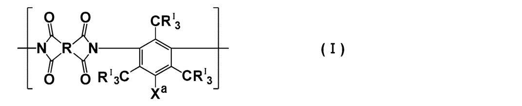
式(I)中、RIは水素原子、アルキル基、又はハロゲン原子を示す。Xaはスルホンアミド基、アルコキシスルホニル基、カルボキシル基、ヒドロキシル基、アシルオキシ基及びハロゲン原子から選ばれる極性基を示す。
Rは下記式(I-1)~(I-28)のいずれか1つで表される構造の基を示す。ここでX1~X3は単結合又は2価の連結基を、Lは-CH=CH-又は-CH2-を、R1及びR2は水素原子又は置換基を示し、*は式(I)中のカルボニル基との結合部位を示す。
Rは式(I-1)、(I-2)又は(I-4)で表される基であることが好ましく、(I-1)又は(I-4)で表される基であることがより好ましく、(I-1)で表される基であることが特に好ましい。
Rは下記式(I-1)~(I-28)のいずれか1つで表される構造の基を示す。ここでX1~X3は単結合又は2価の連結基を、Lは-CH=CH-又は-CH2-を、R1及びR2は水素原子又は置換基を示し、*は式(I)中のカルボニル基との結合部位を示す。
Rは式(I-1)、(I-2)又は(I-4)で表される基であることが好ましく、(I-1)又は(I-4)で表される基であることがより好ましく、(I-1)で表される基であることが特に好ましい。

上記式(I-1)、(I-9)及び(I-18)中、X1~X3は、単結合又は2価の連結基を示す。この2価の連結基としては、-C(Rx)2-(Rxは水素原子又は置換基を示す。Rxが置換基の場合、互いに連結して環を形成してもよい)、-O-、-SO2-、-C(=O)-、-S-、-NRY-(RYは水素原子、アルキル基(好ましくはメチル基又はエチル基)又はアリール基(好ましくはフェニル基))、-C6H4-(フェニレン基)、又はこれらの組み合わせが好ましく、-C(Rx)2-がより好ましい。Rxが置換基を示すとき、その具体例としては、特開2015-160201号公報の<0055>~<0060>に記載の置換基群Zから選ばれる基が挙げられ、中でもアルキル基(好ましい範囲は特開2015-160201号公報の<0055>~<0060>に記載の置換基群Zに示されたアルキル基と同義である)が好ましく、ハロゲン原子を置換基として有するアルキル基がより好ましく、トリフルオロメチルが特に好ましい。なお、式(I-18)は、X3が、X3よりも左側(紙面の左側。以下、左右について同じ)に記載された2つの炭素原子のいずれか一方、及び、X3よりも右側に記載された2つの炭素原子のうちいずれか一方と連結していることを意味する。
上記式(I-4)、(I-15)、(I-17)、(I-20)、(I-21)及び(I-23)中、Lは-CH=CH-又は-CH2-を示す。(I-23)中の複数のLは同じであっても異なっていてもよい。
上記式(I-7)中、R1及びR2は水素原子又は置換基を示す。その置換基としては、特開2015-160201号公報の<0055>~<0060>に記載の置換基群Zから選ばれる基が挙げられる。R1及びR2は互いに結合して環を形成していてもよい。
R1、R2は水素原子又はアルキル基であることが好ましく、水素原子、メチル基又はエチル基であることがより好ましく、水素原子であることが更に好ましい。
式(I-1)~(I-28)中に示された炭素原子には、置換基が付加していてもよい。この置換基の具体例としては、特開2015-160201号公報の<0055>~<0060>に記載の置換基群Zから選ばれる基が挙げられ、なかでもアルキル基又はアリール基が好ましい。
上記式(I)中、RIは水素原子、アルキル基又はハロゲン原子を示す。このアルキル基は直鎖でも分岐を有してもよい。RIとして採り得るアルキル基は、その炭素数が好ましくは1~5、より好ましくは1~3、さらに好ましくは1又は2である。RIとして採り得るアルキル基はその鎖中にヘテロ原子(好ましくは酸素原子又は硫黄原子)を有していてもよい。RIとして好適な具体例としては、メチル基又はエチル基が挙げられ、メチル基がより好ましい。
RIとして採り得るハロゲン原子としては、例えば臭素原子、塩素原子、ヨウ素原子及びフッ素原子が挙げられ、より好ましくは臭素原子である。
RIは、より好ましくは水素原子、メチル基又は臭素原子であり、さらに好ましくは、水素原子又はメチル基であり、さらに好ましくは水素原子である。
RIとして採り得るハロゲン原子としては、例えば臭素原子、塩素原子、ヨウ素原子及びフッ素原子が挙げられ、より好ましくは臭素原子である。
RIは、より好ましくは水素原子、メチル基又は臭素原子であり、さらに好ましくは、水素原子又はメチル基であり、さらに好ましくは水素原子である。
式(I)中、Xaは、スルホンアミド基、アルコキシスルホニル基、カルボキシル基、ヒドロキシル基、アシルオキシ基及びハロゲン原子から選ばれる極性基である。
Xaとして採り得るスルホンアミド基は、無置換であっても、置換基を有する形態であってもよい。なかでもXaとして採り得るスルホンアミド基は、無置換であるか、又は、モノアルキル置換もしくはジアルキル置換であることが好ましく、無置換であるか、又は、モノアルキル置換であることがより好ましく、無置換であることが特に好ましい。つまり、Xaとして採り得るスルホンアミド基が置換基を有する場合、この置換基はアルキル基が好ましい。このアルキル基は、直鎖でも分岐を有していてもよく、その炭素数は1~10が好ましく、1~5がより好ましく、1~3がより好ましい。また、このアルキル基は置換基としてハロゲン原子を有することも好ましく、置換基としてフッ素原子を有することがより好ましい。スルホンアミド基が有するアルキル基の好ましい具体例としては、メチル基、エチル基、n-プロピル基、-CH2CF2CF2CF3、-CH2CF2CF3及び-CH2CF3が挙げられる。
なかでも、スルホンアミド基がモノアルキル置換である場合、このアルキル基はメチル基であるか、置換基としてフッ素原子を有するアルキル基であることが好ましく、より好ましくはメチル基、-CH2CF2CF2CF3又は-CH2CF3である。
また、スルホンアミド基がジアルキル置換である場合、このアルキル基はメチル基であることが好ましい。
Xaとして採り得るスルホンアミド基は、無置換であっても、置換基を有する形態であってもよい。なかでもXaとして採り得るスルホンアミド基は、無置換であるか、又は、モノアルキル置換もしくはジアルキル置換であることが好ましく、無置換であるか、又は、モノアルキル置換であることがより好ましく、無置換であることが特に好ましい。つまり、Xaとして採り得るスルホンアミド基が置換基を有する場合、この置換基はアルキル基が好ましい。このアルキル基は、直鎖でも分岐を有していてもよく、その炭素数は1~10が好ましく、1~5がより好ましく、1~3がより好ましい。また、このアルキル基は置換基としてハロゲン原子を有することも好ましく、置換基としてフッ素原子を有することがより好ましい。スルホンアミド基が有するアルキル基の好ましい具体例としては、メチル基、エチル基、n-プロピル基、-CH2CF2CF2CF3、-CH2CF2CF3及び-CH2CF3が挙げられる。
なかでも、スルホンアミド基がモノアルキル置換である場合、このアルキル基はメチル基であるか、置換基としてフッ素原子を有するアルキル基であることが好ましく、より好ましくはメチル基、-CH2CF2CF2CF3又は-CH2CF3である。
また、スルホンアミド基がジアルキル置換である場合、このアルキル基はメチル基であることが好ましい。
また、Xaとして採り得るスルホンアミド基は置換基としてシクロアルキル基を有することも好ましい。このシクロアルキル基は、炭素数が3~15が好ましく、6~10がより好ましい。中でも上記シクロアルキル基はアダマンチル基であることが好ましい。Xaとして採り得るスルホンアミド基が置換基としてシクロアルキル基を有する場合、このスルホンアミド基が有するシクロアルキル基の数は1つが好ましい。すなわち、このスルホンアミド基はモノ置換体であることが好ましい。
Xaとして採り得るスルホンアミド基は無置換であることがさらに好ましい。
Xaとして採り得るアルコキシスルホニル基は、その炭素数が1~5が好ましく、1~3がより好ましい。Xaとして採り得るアルコキシスルホニル基におけるアルコキシ基は、メトキシ基又はエトキシ基が好ましく、メトキシ基がさらに好ましい。
Xaとして採り得るアシルオキシ基は、その炭素数が2~5が好ましく、2又は3がより好ましく、中でもアセトキシ基が特に好ましい。
Xaとして採り得るハロゲン原子としては、例えば臭素原子、塩素原子、ヨウ素原子及びフッ素原子が挙げられ、好ましくは臭素原子である。
Xaはスルホンアミド基、アルコキシスルホニル基、カルボキシル基、ヒドロキシル基及びアシルオキシ基が好ましく、より好ましくはスルホンアミド基、アルコキシスルホニル基、カルボキシル基及びヒドロキシル基であり、特に好ましくはスルホンアミド基、カルボキシル基及びヒドロキシル基であり、より特に好ましくはスルホンアミド基である。
上記式(I)の繰り返し単位を有するポリイミドを用いて第一の分離層を形成することで、得られるガス分離膜のガス透過性、ガス分離選択性、可塑化耐性のいずれも、より向上させることができる。その理由は定かではないが、式(I)で表される繰り返し単位がジアミン成分中にCRI
3を3つ有することにより、ポリイミドの平面性ないしパッキング性がほどよく抑制され、自由体積分率が大きくなり、ガス透過性が向上するものと推定される。また、式(I)で表される繰り返し単位がXaとして特定の極性基を有することにより、ポリイミドが適度に緻密化してその運動性が低下し、これにより動的分子径の大きな分子についてはその透過性を効果的に抑えることができ、ガス分離選択性もより向上させることができるものと推定される。
上記式(I)の繰り返し単位を有するポリイミドは、CRI 3基を3つ有するジアミン成分を有する。このようにアルキル基を多く有するポリイミドは極性が低いために、トルエン等の低極性の不純物との親和性が高まり、可塑化耐性に劣る傾向がある。しかし、式(I)の繰り返し単位を有するポリイミドは、そのジアミン成分中に、3つのCRI 3基に加えて特定の極性基Xaを特定の部位に有する。これにより、高度なガス透過性とガス分離選択性を示し、且つ、極性基により不純物との親和性が抑えられ、可塑化耐性にも優れたガス分離膜を作り出すことができるものと推定される。
上記式(I)の繰り返し単位を有するポリイミドは、CRI 3基を3つ有するジアミン成分を有する。このようにアルキル基を多く有するポリイミドは極性が低いために、トルエン等の低極性の不純物との親和性が高まり、可塑化耐性に劣る傾向がある。しかし、式(I)の繰り返し単位を有するポリイミドは、そのジアミン成分中に、3つのCRI 3基に加えて特定の極性基Xaを特定の部位に有する。これにより、高度なガス透過性とガス分離選択性を示し、且つ、極性基により不純物との親和性が抑えられ、可塑化耐性にも優れたガス分離膜を作り出すことができるものと推定される。
ポリイミドは、架橋剤により架橋された形態であってもよい。
例えば、極性基Xaが無置換、又はモノ置換のスルホンアミド基を有する場合、スルホンアミド基のNH基を介して架橋構造を形成させる目的で、オルトチタン酸テトライソプロピルのような金属アルコキシドを架橋剤として用いることができる。また、CRI 3がハロゲン原子を有する場合、求核付加反応させる目的で、ジメチルアミノプロピルトリエトキシシランやテトラメチルエチレンジアミンのような架橋剤を用いることができる。
さらに、本発明に用いるポリイミドが後述する式(II-a)又は(II-b)で表される繰り返し単位を含む場合、ポリイミドは、これらの繰り返し単位に含まれる官能基と反応可能な基を有する架橋剤により架橋された形態であってもよい。
例えば、極性基Xaが無置換、又はモノ置換のスルホンアミド基を有する場合、スルホンアミド基のNH基を介して架橋構造を形成させる目的で、オルトチタン酸テトライソプロピルのような金属アルコキシドを架橋剤として用いることができる。また、CRI 3がハロゲン原子を有する場合、求核付加反応させる目的で、ジメチルアミノプロピルトリエトキシシランやテトラメチルエチレンジアミンのような架橋剤を用いることができる。
さらに、本発明に用いるポリイミドが後述する式(II-a)又は(II-b)で表される繰り返し単位を含む場合、ポリイミドは、これらの繰り返し単位に含まれる官能基と反応可能な基を有する架橋剤により架橋された形態であってもよい。
上記式(I)で表される繰り返し単位は、下記式(I-a)で表される繰り返し単位であることが好ましい。

式(I-a)中、R及びXaは、それぞれ上記式(I)におけるR及びXaと同義であり、好ましい形態も同じである。
上記式(I-a)で表される繰り返し単位は、下記式(I-b)で表される繰り返し単位であることが好ましい。
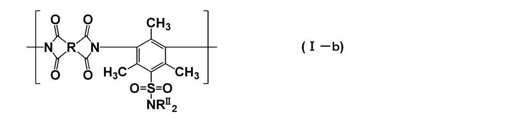
式(I-b)中、Rは上記式(I-a)におけるRと同義であり、好ましい形態も同じである。
RIIは水素原子又は置換基を示す。2つのRIIのうち少なくとも1つのRIIが水素原子であることが好ましく、2つのRIIがいずれも水素原子であることがさらに好ましい。RIIが置換基である場合、特開2015-160201号公報の<0055>~<0060>に記載の置換基群Zから選ばれる基が好ましく、アルキル基又はシクロアルキル基がより好ましい。
RIIとして採り得るアルキル基は、直鎖でも分岐を有していてもよく、その炭素数は1~10が好ましく、1~5がより好ましく、1~3が特に好ましい。また、このアルキル基は置換基としてハロゲン原子を有することも好ましく、置換基としてフッ素原子を有することがより好ましい。RIIがアルキル基の場合の好ましい具体例としては、メチル基、エチル基、n-プロピル基、-CH2CF2CF2CF3、-CH2CF2CF3、-CH2CF3が挙げられる。
2つのRIIのうち一方が水素原子で、他方がアルキル基の場合、このアルキル基は、メチル基であるか、置換基としてフッ素原子を有するアルキル基であることが好ましく、より好ましくは、メチル基、-CH2CF2CF2CF3又は-CH2CF3である。
また、2つのRIIがいずれもアルキル基の場合、このアルキル基はメチル基が好ましい。
RIIは水素原子又は置換基を示す。2つのRIIのうち少なくとも1つのRIIが水素原子であることが好ましく、2つのRIIがいずれも水素原子であることがさらに好ましい。RIIが置換基である場合、特開2015-160201号公報の<0055>~<0060>に記載の置換基群Zから選ばれる基が好ましく、アルキル基又はシクロアルキル基がより好ましい。
RIIとして採り得るアルキル基は、直鎖でも分岐を有していてもよく、その炭素数は1~10が好ましく、1~5がより好ましく、1~3が特に好ましい。また、このアルキル基は置換基としてハロゲン原子を有することも好ましく、置換基としてフッ素原子を有することがより好ましい。RIIがアルキル基の場合の好ましい具体例としては、メチル基、エチル基、n-プロピル基、-CH2CF2CF2CF3、-CH2CF2CF3、-CH2CF3が挙げられる。
2つのRIIのうち一方が水素原子で、他方がアルキル基の場合、このアルキル基は、メチル基であるか、置換基としてフッ素原子を有するアルキル基であることが好ましく、より好ましくは、メチル基、-CH2CF2CF2CF3又は-CH2CF3である。
また、2つのRIIがいずれもアルキル基の場合、このアルキル基はメチル基が好ましい。
RIIとして採り得るシクロアルキル基は、その炭素数が3~15であることが好ましく、6~10であることがより好ましい。RIIがシクロアルキル基の場合、好ましくはアダマンチル基である。2つのRIIのうち一方がシクロアルキル基の場合、他方は水素原子であることが好ましい。
上記式(I-b)で表される繰り返し単位は、下記式(I-c)で表される繰り返し単位であることが好ましい。

式(I-c)中、Rは式(I-b)におけるRと同義であり、好ましい形態も同じである。
本発明に用いるポリイミドは、上記式(I)で表される繰り返し単位に加えて、下記式(II-a)又は(II-b)で表される繰り返し単位を有してもよい。


上記式(II-a)及び(II-b)中、Rは式(I)中のRと同義であり、好ましい範囲も同じである。R4~R6は置換基を示す。置換基としては、特開2015-160201号公報の<0055>~<0060>に記載の置換基群Zから選ばれる基が挙げられる。
R4はアルキル基、カルボキシル基又はハロゲン原子であることが好ましい。R4の数を示すl1は0~4の整数であり、R4がアルキル基の場合、l1は1~4であることが好ましく、2~4であることがより好ましく、特に好ましくは3又は4である。R4がカルボキシル基の場合、l1は1~2であることが好ましく、より好ましくは1である。R4がアルキル基である場合、このアルキル基の炭素数は1~10であることが好ましく、1~5であることがより好ましく、1~3であることが特に好ましい。R4がアルキル基である場合、より特に好ましくはメチル基、エチル基又はトリフルオロメチル基である。
式(II-a)において、ジアミン成分中のR4を有しうるフェニレン基が、ポリイミドに組み込まれるために、2つの連結部位は互いにメタ位又はパラ位に位置することが好ましく、互いにパラ位に位置することがより好ましい。
本発明において、上記式(II-a)で表される構造には、上記式(I)で表される構造は含まれないものとする。
R4はアルキル基、カルボキシル基又はハロゲン原子であることが好ましい。R4の数を示すl1は0~4の整数であり、R4がアルキル基の場合、l1は1~4であることが好ましく、2~4であることがより好ましく、特に好ましくは3又は4である。R4がカルボキシル基の場合、l1は1~2であることが好ましく、より好ましくは1である。R4がアルキル基である場合、このアルキル基の炭素数は1~10であることが好ましく、1~5であることがより好ましく、1~3であることが特に好ましい。R4がアルキル基である場合、より特に好ましくはメチル基、エチル基又はトリフルオロメチル基である。
式(II-a)において、ジアミン成分中のR4を有しうるフェニレン基が、ポリイミドに組み込まれるために、2つの連結部位は互いにメタ位又はパラ位に位置することが好ましく、互いにパラ位に位置することがより好ましい。
本発明において、上記式(II-a)で表される構造には、上記式(I)で表される構造は含まれないものとする。
R5及びR6はアルキル基もしくはハロゲン原子を示すか、又は互いに連結してX4と共に環を形成する基を示すことが好ましい。また、2つのR5が連結して環を形成している形態や、2つのR6が連結して環を形成している形態も好ましい。R5とR6が連結した構造としては特に制限はないが、単結合、-O-又は-S-が好ましい。R5及びR6の数を示すm1及びn1は0~4の整数であり、1~4であることが好ましく、2~4であることがより好ましく、特に好ましくは3又は4である。R5及びR6がアルキル基である場合、このアルキル基の炭素数は1~10であることが好ましく、1~5であることがより好ましく、1~3であることが特に好ましい。R5及びR6がアルキル基である場合、より特に好ましくはメチル基、エチル基又はトリフルオロメチル基である。
X4は上記式(I-1)におけるX1と同義であり、好ましい範囲も同一である。
ポリイミドは、その構造中、上記式(I)で表される繰り返し単位と、上記式(II-a)で表される繰り返し単位と、上記式(II-b)で表される繰り返し単位の総モル量中に占める、式(I)で表される繰り返し単位のモル量の割合が50~100モル%であることが好ましく、70~100モル%がより好ましく、80~100モル%が特に好ましく、90~100モル%がより特に好ましい。なお、上記式(I)で表される繰り返し単位と、上記式(II-a)で表される繰り返し単位と、上記式(II-b)で表される繰り返し単位の総モル量中に占める、式(I)で表される繰り返し単位のモル量の割合が100モル%であるとは、ポリイミドが、上記式(II-a)で表される繰り返し単位と、上記式(II-b)で表される繰り返し単位のいずれも有しないことを意味する。
ポリイミドは、上記式(I)で表される繰り返し単位からなるか、又は、上記式(I)で表される繰り返し単位以外の繰り返し単位を有していてもよい。
上記式(I)で表される繰り返し単位以外の繰り返し単位を有する場合には、上記式(I)で表される繰り返し単位以外の残部が、上記式(II-a)又は上記式(II-b)で表される繰り返し単位からなることが好ましい。ここで、「上記式(II-a)又は上記式(II-b)で表される繰り返し単位からなる」とは、上記式(II-a)で表される繰り返し単位からなる態様、上記式(II-b)で表される繰り返し単位からなる態様、並びに、上記式(II-a)で表される繰り返し単位と上記式(II-b)で表される繰り返し単位とからなる態様の3つの態様を含む意味である。
上記式(I)で表される繰り返し単位以外の繰り返し単位を有する場合には、上記式(I)で表される繰り返し単位以外の残部が、上記式(II-a)又は上記式(II-b)で表される繰り返し単位からなることが好ましい。ここで、「上記式(II-a)又は上記式(II-b)で表される繰り返し単位からなる」とは、上記式(II-a)で表される繰り返し単位からなる態様、上記式(II-b)で表される繰り返し単位からなる態様、並びに、上記式(II-a)で表される繰り返し単位と上記式(II-b)で表される繰り返し単位とからなる態様の3つの態様を含む意味である。
本発明のガス分離膜は、第一の分離層の樹脂が、分離選択性とガス透過性の観点から、4,4’-(ヘキサフルオロイソプロピリデン)ジフタル酸無水物(6FDA)に由来する構造を含むポリイミドであることが好ましい。すなわち、母核Rは式(I-1)で表される基であり、X1が-C(Rx)2-であり、Rxがトリフルオロメチルであることが好ましい。
なお、本明細書において「互いに連結して環を形成してもよい」というときには、単結合、二重結合等により結合して環状構造を形成するものであってもよく、また、縮合して縮環構造を形成するものであってもよい。
なお、本明細書において「互いに連結して環を形成してもよい」というときには、単結合、二重結合等により結合して環状構造を形成するものであってもよく、また、縮合して縮環構造を形成するものであってもよい。
特開2015-160201号公報の<0055>~<0060>に記載の置換基群Zは、更に置換基群Zより選択されるいずれか1つ以上の置換基により置換されてもよい。
なお、本発明において、1つの構造部位に複数の置換基があるときには、それらの置換基は互いに連結して環を形成していたり、上記構造部位の一部又は全部と縮環して芳香族環もしくは不飽和複素環を形成していたりしてもよい。
なお、本発明において、1つの構造部位に複数の置換基があるときには、それらの置換基は互いに連結して環を形成していたり、上記構造部位の一部又は全部と縮環して芳香族環もしくは不飽和複素環を形成していたりしてもよい。
化合物ないし置換基等がアルキル基、アルケニル基等を含むとき、これらは直鎖状でも分岐状でもよく、置換されていても無置換でもよい。またアリール基、ヘテロ環基等を含むとき、それらは単環でも縮環でもよく、置換されていても無置換でもよい。
本明細書において、単に置換基としてしか記載されていないものは、特に断わりのない限り特開2015-160201号公報の<0055>~<0060>に記載の置換基群Zを参照するものであり、また、各々の基の名称が記載されているだけのとき(例えば、「アルキル基」と記載されているだけのとき)は、この置換基群Zの対応する基における好ましい範囲および/または具体例が適用される。
本明細書において、単に置換基としてしか記載されていないものは、特に断わりのない限り特開2015-160201号公報の<0055>~<0060>に記載の置換基群Zを参照するものであり、また、各々の基の名称が記載されているだけのとき(例えば、「アルキル基」と記載されているだけのとき)は、この置換基群Zの対応する基における好ましい範囲および/または具体例が適用される。
本発明に用いることができるポリイミドの分子量は、好ましくは重量平均分子量として10,000~1000,000であることが好ましく、より好ましくは15,000~500,000であり、さらに好ましくは20,000~200,000である。
本明細書において分子量及び分散度は特に断らない限りゲル浸透クロマトグラフィー(GPC、gel permeation chromatography)法を用いて測定した値とし、分子量はポリスチレン換算の重量平均分子量とする。GPC法に用いるカラムに充填されているゲルは芳香族化合物を繰り返し単位に持つゲルが好ましく、例えばスチレン-ジビニルベンゼン共重合体からなるゲルが挙げられる。
カラムは2~6本連結させて用いることが好ましい。
用いる溶媒は、テトラヒドロフラン等のエーテル系溶媒、N-メチルピロリジノン等のアミド系溶媒が挙げられる。
測定は、溶媒の流速が0.1~2mL/分の範囲で行うことが好ましく、0.5~1.5mL/分の範囲で行うことが最も好ましい。この範囲内で測定を行うことで、装置に負荷がかからず、さらに効率的に測定ができる。
測定温度は10~50℃で行うことが好ましく、20~40℃で行うことがより好ましい。
なお、使用するカラム及び溶媒は測定対称となる高分子化合物の物性に応じて適宜選択することができる。
カラムは2~6本連結させて用いることが好ましい。
用いる溶媒は、テトラヒドロフラン等のエーテル系溶媒、N-メチルピロリジノン等のアミド系溶媒が挙げられる。
測定は、溶媒の流速が0.1~2mL/分の範囲で行うことが好ましく、0.5~1.5mL/分の範囲で行うことが最も好ましい。この範囲内で測定を行うことで、装置に負荷がかからず、さらに効率的に測定ができる。
測定温度は10~50℃で行うことが好ましく、20~40℃で行うことがより好ましい。
なお、使用するカラム及び溶媒は測定対称となる高分子化合物の物性に応じて適宜選択することができる。
本発明に用いうる反応性基を有するポリイミドは、特定の2官能酸無水物(テトラカルボン酸二無水物)と特定のジアミンとを縮合重合させることで合成することができる。その方法としては一般的な成書(例えば、今井淑夫、横田力男編著、「最新ポリイミド~基礎と応用~」、株式会社エヌ・ティー・エス発行、2010年8月25日、3~49頁など)に記載の手法を適宜選択することができる。
本発明に用いられるポリイミドの合成において、一方の原料であるテトラカルボン酸二無水物の少なくとも1種類は、下記式(IV)で表されることが好ましい。原料とするテトラカルボン酸二無水物のすべてが下記式(IV)で表されることがより好ましい。

式(IV)中、Rは上記式(I)におけるRと同義である。
本発明に用いうるテトラカルボン酸二無水物の具体例としては、例えば以下に示すものが挙げられる。


本発明に用いられるポリイミドの合成において、他方の原料であるジアミン化合物の少なくとも1種類は、下記式(V)で表されることが好ましい。

式(V)中、RI及びXaは、それぞれ上記式(I)におけるRI及びXaと同義である。
式(V)で表されるジアミン化合物の具体例としては、例えば、下記に示すものを挙げることができるが、本発明はこれらに限定されるものではない。なお、本明細書において、Meはメチル、Etはエチルを意味する。
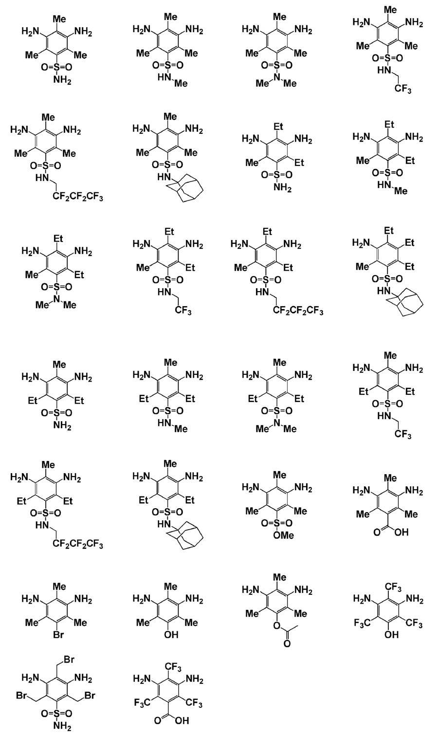
また、本発明に用いられるポリイミドの合成において、原料とするジアミン化合物として、上記式(V)で表されるジアミン化合物に加えて、下記式(VII-a)又は下記式(VII-b)で表されるジアミン化合物を用いてもよい。
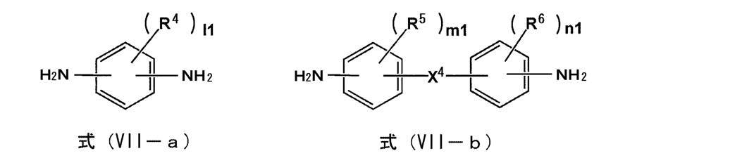
式(VII-a)中、R4及びl1は、それぞれ上記式(II-a)におけるR4及びl1と同義である。式(VII-a)で表されるジアミン化合物には、式(V)で表されるジアミン化合物は含まれない。
式(VII-b)中、R5、R6、X4、m1及びn1は、それぞれ上記式(II-b)におけるR5、R6、X4、m1及びn1と同義である。
式(VII-b)中、R5、R6、X4、m1及びn1は、それぞれ上記式(II-b)におけるR5、R6、X4、m1及びn1と同義である。
式(VII-a)又は(VII-b)で表されるジアミンとして、例えば下記に示すものを用いることができる。


上記式(IV)で表されるモノマーと、上記式(V)、(VII-a)又は(VII-b)で表されるモノマーは、予めオリゴマー又はプレポリマーとして用いてもよい。本発明に用いられるポリイミドは、ブロック共重合体、ランダム共重合体、グラフト共重合体のいずれでもよい。
一般式(I)で表されるポリイミドとしては、後述の実施例で用いるポリイミド(P-02)を好ましく用いることができる。
特開2015-160201号公報の<0040>~<0068>に記載のポリイミドとしては、特開2015-160201号公報の<0068>の例示ポリイミドP-100において共重合比(モル比)xが20で、yが80としたポリイミド(P-101)を好ましく用いることができる。
特開2015-160201号公報の<0040>~<0068>に記載のポリイミドとしては、特開2015-160201号公報の<0068>の例示ポリイミドP-100において共重合比(モル比)xが20で、yが80としたポリイミド(P-101)を好ましく用いることができる。
また、分離層の樹脂がポリイミドである場合、より具体的には、Huntsman Advanced Materials社よりMatrimid(登録商標)の商標で販売されているMatrimid 5218およびHP Polymers GmbH社よりそれぞれ商品名P84および商品名P84HTで販売されているP84またはP84HT等も好ましい。
一方、ポリイミド以外の分離層の樹脂としては、セルロースアセテート、セルローストリアセテート、セルロースアセテートブチレート、セルロースプロピオネート、エチルセルロース、メチルセルロース、ニトロセルロース等のセルロース類を選択することができる。
分離層に用いることができるセルロース類としては、全アシル基の置換度が2.0~2.7であることが好ましい。酢酸セルロースL-40(アシル基置換度2.5 株式会社ダイセル製)として市販されているセルロースアセテートも好ましく用いることができる。
分離層に用いることができるセルロース類としては、全アシル基の置換度が2.0~2.7であることが好ましい。酢酸セルロースL-40(アシル基置換度2.5 株式会社ダイセル製)として市販されているセルロースアセテートも好ましく用いることができる。
その他の分離層の樹脂としては、ポリエチレングリコール♯200ジアクリレート(新中村化学社製)の重合したポリマーなどのポリエチレングリコール類、また、特表2010-513021号公報に記載のポリマーなどを選択することができる。
<第二の分離層>
本発明のガス分離膜は、第二の分離層を含み、第二の分離層は、フッ素原子の数の炭素原子の数に対する比であるF/C比の最大値が0.20以上であり、かつ、F/C比が最大値をとる部分におけるSi/C比が0.3以下である。
本発明のガス分離膜は、第二の分離層を含み、第二の分離層は、フッ素原子の数の炭素原子の数に対する比であるF/C比の最大値が0.20以上であり、かつ、F/C比が最大値をとる部分におけるSi/C比が0.3以下である。
(厚み)
第二の分離層の厚みとしては機械的強度、ガス分離選択性、ガス透過性を付与する条件において可能な限り薄膜であることが好ましい。
本発明のガス分離膜は、第二の分離層の厚みが20~200nmであることが好ましく、20~150nmであることがより好ましく、30~100nmであることが特に好ましい。
第二の分離層の厚みとしては機械的強度、ガス分離選択性、ガス透過性を付与する条件において可能な限り薄膜であることが好ましい。
本発明のガス分離膜は、第二の分離層の厚みが20~200nmであることが好ましく、20~150nmであることがより好ましく、30~100nmであることが特に好ましい。
(層構成)
第2の分離層は、単層であっても、2層以上の層であってもよい。
ガス分離膜は第2の分離層を1~5層有することが好ましく、1~3層有することがより好ましく、製造コストの観点から1~2層有することが特に好ましく、単層であることがより特に好ましい。
第2の分離層が2層以上の層である場合、第2の分離層は同一の層が2層以上積層していても、異なる層が2層以上積層していてもよい。
第2の分離層は、単層であっても、2層以上の層であってもよい。
ガス分離膜は第2の分離層を1~5層有することが好ましく、1~3層有することがより好ましく、製造コストの観点から1~2層有することが特に好ましく、単層であることがより特に好ましい。
第2の分離層が2層以上の層である場合、第2の分離層は同一の層が2層以上積層していても、異なる層が2層以上積層していてもよい。
(F/C比)
第二の分離層は、フッ素原子の数の炭素原子の数に対する比であるF/C比の最大値が0.20以上であり、不純物ガス暴露後のガス分離選択性低下を抑制する観点から、0.2~2であることが好ましく、0.25~1.6であることが特に好ましい。
第二の分離層は、フッ素原子の数の炭素原子の数に対する比であるF/C比の最大値が0.20以上であり、不純物ガス暴露後のガス分離選択性低下を抑制する観点から、0.2~2であることが好ましく、0.25~1.6であることが特に好ましい。
(Si/C比)
第二の分離層は、F/C比が最大値をとる部分におけるSi/C比が0.3以下であり、ガス分離選択性の観点から、0.2以下であることが好ましく、0.1以下であることがより好ましく、0であることが特に好ましい。
第二の分離層は、F/C比が最大値をとる部分におけるSi/C比が0.3以下であり、ガス分離選択性の観点から、0.2以下であることが好ましく、0.1以下であることがより好ましく、0であることが特に好ましい。
(第二の分離層の自由体積径)
本発明のガス分離膜は、第二の分離層の自由体積径が0.6nm以上であることが好ましく、0.6~0.86nmであることがより好ましく、0.6~0.74nmであることが特に好ましい。
第二の分離層の自由体積径は、陽電子消滅法により求めたτ3から、第二の分離層の自由体積径(第二の分離層の空孔の直径)を、半経験式:S. T. Tao, J. Chem. Phys., 56, 5499 (1972))に基づいて計算することができる。具体的には、陽電子消滅法では、陽電子が極めて小さいことを利用し、他手法では測定困難な1Åから10nm程度の孔径の空孔(自由体積孔)の評価を行う方法である。ポリマー等の高分子化合物を含む層の空孔の孔径は、陽電子の寿命スペクトルの長寿命の成分である第三成分を解析し、第三成分(o-Ps)の陽電子寿命τ3を計測することで、計算することができる。陽電子は高分子中で電子と結びつきオルソポジトロニウムo-Psを形成する。このo-Psは空孔中にトラップされ消滅すると考えられている。その時のo-Psの寿命τ3は空孔の半径Rの関数で表される。陽電子寿命の解析は非線形最小二乗プログラムPOSITRONFITを用い、行うことができる。同時に空孔の空孔率を表す、第三成分の相対強度I3も計算される。
また、電子線形加速器利用陽電子ビーム装置を用いると、陽電子の打ち込みエネルギーを変えることが出来、低エネルギーではより表面の、高エネルギーではより内部の空孔の情報を得ることが可能である。1keVの打ち込みエネルギーでは主に表面から深さ方向に約20nm、3keVの打ち込みエネルギーでは主に表面から深さ方向に200nmの情報を得ることができる。
第二の分離層の表面から陽電子を1keVの強さで打ち込んだ場合の第三成分の陽電子寿命τ3が例えば2.14ns以上であると、第二の分離層の表面から深さ方向(支持体方向)に約20nmに平均すると孔径が0.6nm以上の空孔が存在していると予想される。このような孔径の空孔が第二の分離層の表面から深さ方向(支持体方向)に約20nmに存在していることで、第二の分離層はCO2とCH4の分離において適度な孔径を有し、ガス透過性とガス分離選択性をともに高くできる。
本発明のガス分離膜は、第二の分離層の自由体積径が0.6nm以上であることが好ましく、0.6~0.86nmであることがより好ましく、0.6~0.74nmであることが特に好ましい。
第二の分離層の自由体積径は、陽電子消滅法により求めたτ3から、第二の分離層の自由体積径(第二の分離層の空孔の直径)を、半経験式:S. T. Tao, J. Chem. Phys., 56, 5499 (1972))に基づいて計算することができる。具体的には、陽電子消滅法では、陽電子が極めて小さいことを利用し、他手法では測定困難な1Åから10nm程度の孔径の空孔(自由体積孔)の評価を行う方法である。ポリマー等の高分子化合物を含む層の空孔の孔径は、陽電子の寿命スペクトルの長寿命の成分である第三成分を解析し、第三成分(o-Ps)の陽電子寿命τ3を計測することで、計算することができる。陽電子は高分子中で電子と結びつきオルソポジトロニウムo-Psを形成する。このo-Psは空孔中にトラップされ消滅すると考えられている。その時のo-Psの寿命τ3は空孔の半径Rの関数で表される。陽電子寿命の解析は非線形最小二乗プログラムPOSITRONFITを用い、行うことができる。同時に空孔の空孔率を表す、第三成分の相対強度I3も計算される。
また、電子線形加速器利用陽電子ビーム装置を用いると、陽電子の打ち込みエネルギーを変えることが出来、低エネルギーではより表面の、高エネルギーではより内部の空孔の情報を得ることが可能である。1keVの打ち込みエネルギーでは主に表面から深さ方向に約20nm、3keVの打ち込みエネルギーでは主に表面から深さ方向に200nmの情報を得ることができる。
第二の分離層の表面から陽電子を1keVの強さで打ち込んだ場合の第三成分の陽電子寿命τ3が例えば2.14ns以上であると、第二の分離層の表面から深さ方向(支持体方向)に約20nmに平均すると孔径が0.6nm以上の空孔が存在していると予想される。このような孔径の空孔が第二の分離層の表面から深さ方向(支持体方向)に約20nmに存在していることで、第二の分離層はCO2とCH4の分離において適度な孔径を有し、ガス透過性とガス分離選択性をともに高くできる。
(有機溶剤への不溶性)
第二の分離層は、架橋されたことが、耐擦性の観点から好ましい。
架橋されたことは、例えば有機溶剤に不溶化していることによって確認することができる。
本発明のガス分離膜は、第二の分離層は、組成比が質量比で1:1であるトルエンおよびヘプタンからなる有機溶剤に不溶であることが、耐擦性の観点から好ましい。
第二の分離層は、加水分解および重縮合して得られるゾル-ゲル硬化物であってもよい。この場合、ゾル-ゲル法反応が、光励起に基づいて開始または促進されることが好ましい。
第二の分離層は、架橋されたことが、耐擦性の観点から好ましい。
架橋されたことは、例えば有機溶剤に不溶化していることによって確認することができる。
本発明のガス分離膜は、第二の分離層は、組成比が質量比で1:1であるトルエンおよびヘプタンからなる有機溶剤に不溶であることが、耐擦性の観点から好ましい。
第二の分離層は、加水分解および重縮合して得られるゾル-ゲル硬化物であってもよい。この場合、ゾル-ゲル法反応が、光励起に基づいて開始または促進されることが好ましい。
(第二の分離層の樹脂)
本発明のガス分離膜は、第二の分離層が樹脂を含むことが好ましい。
第二の分離層の樹脂として、フッ素原子含有樹脂を含むことが好ましい。
なお、第二の分離層の樹脂は、その他の樹脂を含んでいてもよい。
本発明のガス分離膜は、第二の分離層が樹脂を含むことが好ましい。
第二の分離層の樹脂として、フッ素原子含有樹脂を含むことが好ましい。
なお、第二の分離層の樹脂は、その他の樹脂を含んでいてもよい。
-フッ素原子含有樹脂-
第二の分離層の樹脂として用いられるフッ素原子含有樹脂としては特に制限はない。
フッ素樹脂とは、分子中にフッ素原子を含むプラスチックの総称で、例えばアクリル樹脂にフッ素原子が入れば、含フッ素アクリル樹脂となり、フッ素樹脂の1つである。更にフッ素原子を含む樹脂と、フッ素樹脂を含まない樹脂の共重合体についても分子中にフッ素原子を含むのでフッ素樹脂の1つである。このようにフッ素樹脂には非常に広い範囲がある。
第二の分離層の樹脂として、例えば特開平8-052332号公報に記載のフッ素含有ポリイミド、主鎖にヘテロ環構造を含むパーフルオロ樹脂(パーフルオロシクロポリマー)、フルオロ(メタ)アクリレートの重合体およびフルオロオレフィンの重合体を挙げることができる。
本発明のガス分離膜は、第二の分離層の樹脂としてフルオロ(メタ)アクリレートの重合体およびフルオロオレフィンの重合体のうち少なくとも1種類を含むことが好ましい。
第二の分離層の樹脂として用いられるフッ素原子含有樹脂としては特に制限はない。
フッ素樹脂とは、分子中にフッ素原子を含むプラスチックの総称で、例えばアクリル樹脂にフッ素原子が入れば、含フッ素アクリル樹脂となり、フッ素樹脂の1つである。更にフッ素原子を含む樹脂と、フッ素樹脂を含まない樹脂の共重合体についても分子中にフッ素原子を含むのでフッ素樹脂の1つである。このようにフッ素樹脂には非常に広い範囲がある。
第二の分離層の樹脂として、例えば特開平8-052332号公報に記載のフッ素含有ポリイミド、主鎖にヘテロ環構造を含むパーフルオロ樹脂(パーフルオロシクロポリマー)、フルオロ(メタ)アクリレートの重合体およびフルオロオレフィンの重合体を挙げることができる。
本発明のガス分離膜は、第二の分離層の樹脂としてフルオロ(メタ)アクリレートの重合体およびフルオロオレフィンの重合体のうち少なくとも1種類を含むことが好ましい。
フルオロ(メタ)アクリレートの重合体としては、後述のフッ素原子を有するモノマーの一例であるフルオロ(メタ)アクリレートを含む組成物を重合したものを挙げることができる。
また、市販のフルオロ(メタ)アクリレートの重合体をそのまま用いてもよい。
その他のフルオロ(メタ)アクリレートの重合体として、特開昭60-118217号公報の<0014>~<0022>に記載の含フッ素アクリル酸誘導体ポリマーを挙げることができ、この公報の内容は本明細書に組み込まれる。
また、市販のフルオロ(メタ)アクリレートの重合体をそのまま用いてもよい。
その他のフルオロ(メタ)アクリレートの重合体として、特開昭60-118217号公報の<0014>~<0022>に記載の含フッ素アクリル酸誘導体ポリマーを挙げることができ、この公報の内容は本明細書に組み込まれる。
フルオロオレフィンの重合体としては、フルオロオレフィンの単独重合体または共重合体や、フルオロオレフィンとビニルエーテルとの交互共重合体が挙げられる。
フルオロオレフィンの単独重合体または共重合体としては、4フッ化エチレン樹脂又はそのオリゴマー、4フッ化エチレン-6フッ化プロピレン共重合体樹脂などを挙げることができる。
フルオロオレフィンとビニルエーテルとの交互共重合体としては、4フッ化エチレン-フッ化ビニルエーテル共重合体樹脂などを挙げることができる。
フルオロオレフィンの重合体としては、特開平5-329343号公報の<0011>に記載の化合物、特表2016-503448号公報の<0016>~<0025>に記載の化合物を挙げることができ、これらの公報の内容は本明細書に組み込まれる。
フルオロオレフィンの単独重合体または共重合体としては、4フッ化エチレン樹脂又はそのオリゴマー、4フッ化エチレン-6フッ化プロピレン共重合体樹脂などを挙げることができる。
フルオロオレフィンとビニルエーテルとの交互共重合体としては、4フッ化エチレン-フッ化ビニルエーテル共重合体樹脂などを挙げることができる。
フルオロオレフィンの重合体としては、特開平5-329343号公報の<0011>に記載の化合物、特表2016-503448号公報の<0016>~<0025>に記載の化合物を挙げることができ、これらの公報の内容は本明細書に組み込まれる。
フッ素原子含有樹脂としては、市販品を用いてもよい。
市販品のフッ素原子含有樹脂としては、例えば、旭硝子製サイトップシリーズ(後述の実施例で用いるサイトップCTL809Mなど)、旭硝子製Lumiflonシリーズ、Arkema製のKynarシリーズ、DIC製フルオネートシリーズ(後述の実施例で用いるフルオネート K-704など)、DIC製MEGAFACEシリーズ、DIC製DEFENSA OPシリーズ、Sigma-Aldrich製のNafionシリーズを挙げることができる。
市販品のフッ素原子含有樹脂としては、例えば、旭硝子製サイトップシリーズ(後述の実施例で用いるサイトップCTL809Mなど)、旭硝子製Lumiflonシリーズ、Arkema製のKynarシリーズ、DIC製フルオネートシリーズ(後述の実施例で用いるフルオネート K-704など)、DIC製MEGAFACEシリーズ、DIC製DEFENSA OPシリーズ、Sigma-Aldrich製のNafionシリーズを挙げることができる。
-フッ素原子含有樹脂以外のその他の樹脂-
第二の分離層に用いられるフッ素原子含有樹脂以外のその他の樹脂として、ハロゲン原子含有モノマー以外のその他のモノマーを重合および/または架橋して得られる樹脂を挙げることができる。
ハロゲン原子含有モノマー以外のその他のモノマーについては後述する。
第二の分離層に用いられるフッ素原子含有樹脂以外のその他の樹脂として、ハロゲン原子含有モノマー以外のその他のモノマーを重合および/または架橋して得られる樹脂を挙げることができる。
ハロゲン原子含有モノマー以外のその他のモノマーについては後述する。
第二の分離層は架橋されたことが好ましい。これまで述べた第二の分離層に用いられる樹脂を樹脂前駆体として用い、樹脂前駆体を架橋反応させたものを、第二の分離層の樹脂として用いてもよい。
本発明のガス分離膜は、第二の分離層の樹脂がアクリル酸エステル結合、メタクリル酸エステル結合、ウレタン結合およびエーテル結合のうち少なくとも1種類を含むことが好ましい。
アクリル酸エステル結合およびメタクリル酸エステル結合としては、後述のフルオロ(メタ)アクリレートモノマーが重合した構造、および/または、後述のシリコーンアクリレート系モノマーが重合した構造が好ましい。
ウレタン結合としては、後述のフルオロ(メタ)アクリレートモノマーと、後述の重合開始剤(好ましくは硬化剤、より好ましくはポリイソシアネート)が架橋した構造が好ましい。
エーテル結合としては、後述のフルオロ(メタ)アクリレートモノマーが分子中に含む多価アルコール由来の基と(メタ)アクリロイル基の結合であることが好ましい。
本発明のガス分離膜は、第二の分離層の樹脂がアクリル酸エステル結合、メタクリル酸エステル結合、ウレタン結合およびエーテル結合のうち少なくとも1種類を含むことが好ましい。
アクリル酸エステル結合およびメタクリル酸エステル結合としては、後述のフルオロ(メタ)アクリレートモノマーが重合した構造、および/または、後述のシリコーンアクリレート系モノマーが重合した構造が好ましい。
ウレタン結合としては、後述のフルオロ(メタ)アクリレートモノマーと、後述の重合開始剤(好ましくは硬化剤、より好ましくはポリイソシアネート)が架橋した構造が好ましい。
エーテル結合としては、後述のフルオロ(メタ)アクリレートモノマーが分子中に含む多価アルコール由来の基と(メタ)アクリロイル基の結合であることが好ましい。
(第二の分離層のモノマー)
第二の分離層に用いられるモノマーとして、フッ素原子を有するモノマーと、その他のモノマーを挙げることができる。
第二の分離層に用いられるモノマーとして、フッ素原子を有するモノマーと、その他のモノマーを挙げることができる。
-フッ素原子を有するモノマー-
フッ素原子を有するモノマーとしては、F修飾ジメチルシロキサンモノマー、フルオロアクリレート、フルオロエポキシモノマー、フルオロオレフィンモノマー、フルオロ(メタ)アクリレートを挙げることができる。
その中でも、フルオロ(メタ)アクリレートが好ましい。
具体的には、特開2014-105271号公報の<0019>~<0026>に記載のフッ素原子含有炭化水素基を含有する(メタ)アクリレート化合物、特開2012-99638号公報の<0047>~<0060>および<0126>に記載の化合物を用いることができる。これらの公報の内容は、参照して本明細書に組み込まれる。
フッ素原子を有するモノマーとしては、F修飾ジメチルシロキサンモノマー、フルオロアクリレート、フルオロエポキシモノマー、フルオロオレフィンモノマー、フルオロ(メタ)アクリレートを挙げることができる。
その中でも、フルオロ(メタ)アクリレートが好ましい。
具体的には、特開2014-105271号公報の<0019>~<0026>に記載のフッ素原子含有炭化水素基を含有する(メタ)アクリレート化合物、特開2012-99638号公報の<0047>~<0060>および<0126>に記載の化合物を用いることができる。これらの公報の内容は、参照して本明細書に組み込まれる。
フッ素原子含有炭化水素基を含有する(メタ)アクリレートは、下記式(1)または下記式(2)で表される化合物が好ましい。
(CpFq-O-)r-A-(-O-CO-CR=CH2)s・・・式(1)
式(1)中、
pは1~18の整数、qは3~37の整数、
rは1~18の整数、sは2~19の整数、ただし、r+sは3~20であり、
Aは、多価アルコールの脱水酸基残基、
Rは、水素原子またはメチル基を表す。
式(1)中、
pは1~18の整数、qは3~37の整数、
rは1~18の整数、sは2~19の整数、ただし、r+sは3~20であり、
Aは、多価アルコールの脱水酸基残基、
Rは、水素原子またはメチル基を表す。
(CpFq-O-)r-A(OH)t-(-O-CO-CR=CH2)s-t・・・式(2)
式(2)中、
pは1~18の整数、qは3~37の整数、rは1~18の整数、sは2~19の整数、tは1~18の整数、ただし、r+sは3~20であり、s>tであり、Aは、多価アルコールの脱水酸基残基、Rは、水素原子またはメチル基を表す。
式(2)中、
pは1~18の整数、qは3~37の整数、rは1~18の整数、sは2~19の整数、tは1~18の整数、ただし、r+sは3~20であり、s>tであり、Aは、多価アルコールの脱水酸基残基、Rは、水素原子またはメチル基を表す。
式(1)および(2)におけるCpFq-は、1以上のフッ素原子を含有する炭化水素基を意味し、フッ素原子を1以上有する限り、直鎖、分岐鎖、環状の炭化水素基のいずれでもよく、飽和、不飽和のいずれの炭化水素基でもよい。なかでも、直鎖又は分岐鎖のフルオロアルキル基、フルオロアルケニル基及びフルオロシクロアルキル基が好ましい。pは、2~18が好ましく、2~12がより好ましく、1~10がさらに好ましい。例えば、パーフルオロメチル基、ジフルオロエチル基、パーフルオロエチル基、ペンタフルオロプロピル基、パーフルオロプロピル基、パーフルオロオクチル基、パーフルオロノニル基、パーフルオロシクロペンチル基、パーフルオロシクロヘキシル基等が挙げられる。又は、以下の基も好ましい(式中、*は結合手を表す)。

なかでも、炭化水素の全ての水素原子がフッ素原子に置換されたパーフルオロ基が好ましい。
式(1)および(2)におけるAに用いられる多価アルコールとしては、例えば、ペンタエリスリトール、ジペンタエリスリトール、トリペンタエリスリトール、グリセリン、ジグリセリン、トリグリセリン、ポリグリセリン、ソルビトール、マンニトール、トリメチロールプロパン、ジトリメチロールプロパン、トリメチロールエタン、ジトリメチロールエタン、ビス(ジペンタエタスリトール)アジペート、トリス(2ーヒドロキシエチル)イソシアヌレート;さらに、これら多価アルコールのアルキレン(例えば、エチレン、プロピレン、ブチレン等)オキサイドの付加物;これら多価アルコールのε-カプロラクトン変性物等が挙げられる。
脱水酸基残基とは、多価アルコールのヒドロキシル基から水素原子を取り除いた基のことを言う。
脱水酸基残基とは、多価アルコールのヒドロキシル基から水素原子を取り除いた基のことを言う。
フッ素原子含有炭化水素基を含有する(メタ)アクリレートとしては、例えば、以下の式(1-1)で表される化合物が挙げられる。
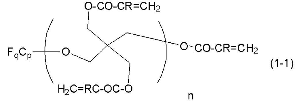
(式(1-1)中、p、q及びRは、上記と同義であり、nは1~5の整数、好ましくは1~3の整数、より好ましくは1又は2を表す。)
(式(1-1)中、p、q及びRは、上記と同義であり、nは1~5の整数、好ましくは1~3の整数、より好ましくは1又は2を表す。)
式(1-1)で表される化合物は、以下の式(1-2)の化合物を含む。
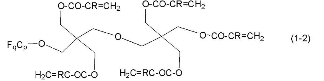
(式(1-2)中、p、q及びRは、上記と同義である。)
(式(1-2)中、p、q及びRは、上記と同義である。)
フッ素原子含有炭化水素基を含有する(メタ)アクリレートは、2~6官能であることが好ましく、2または3官能であることがより好ましく、3官能であることが特に好ましい。フッ素原子含有炭化水素基を含有する(メタ)アクリレートの官能数は、1分子中の-O-CO-CR=CH2の個数を意味する。
フッ素原子含有炭化水素基を含有する(メタ)アクリレートとしては、例えば、トリアクリロイルペンタフルオロエチルペンタエリスリトール、トリアクリロイルヘプタフルオロイソプロピルペンタエリスリトール、トリアクリロイルヘプタデカフルオロノネニルペンタエリスリトール、ペンタアクリロイルペンタフルオロエチルジペンタエリスリトール、ペンタアクリロイルヘプタフルオロイソプロピルジペンタエリスリトール、ペンタアクリロイルヘプタデカフルオロノネニルジペンタエリスリトール等が挙げられる。
さらに、特開2003-313242号公報に記載された化合物等が挙げられる。
さらに、特開2003-313242号公報に記載された化合物等が挙げられる。
フッ素原子を有するモノマーの具体例としては、以下の化合物を挙げることができる。本発明は以下の具体例によって限定されない。
LINC-3A(共栄社化学(株)製):


ジアクリル酸2,2,3,3,4,4,5,5-オクタフルオロ-1,6-ヘキサンジオール:


2,2,2-トリフルオロエチルメタクリレート:

--フッ素含有界面活性剤--
フッ素原子を有するモノマーとして、フッ素含有界面活性剤を用いてもよい。本発明のガス分離膜は、第二の分離層はフッ素含有界面活性剤を含むことが好ましい。
フッ素含有界面活性剤としては、公知の界面活性剤を用いることができる。その中でも、紫外線反応性基を有するフッ素含有界面活性剤を用いることが好ましい。
紫外線反応性基を有するフッ含有系界面活性剤としては、特開2016-11365号公報の<0022>~<0025>に記載の化合物を挙げることができ、この公報の内容は本明細書に組み込まれる。
フッ素含有界面活性剤としては、市販品を用いてもよい。
市販品のフッ素含有界面活性剤としては、例えば、メガファックRS-75(DIC製、フッ素基、親水性基、親油性基および紫外線反応性基含有オリゴマー)などを挙げることができる。
フッ素原子を有するモノマーとして、フッ素含有界面活性剤を用いてもよい。本発明のガス分離膜は、第二の分離層はフッ素含有界面活性剤を含むことが好ましい。
フッ素含有界面活性剤としては、公知の界面活性剤を用いることができる。その中でも、紫外線反応性基を有するフッ素含有界面活性剤を用いることが好ましい。
紫外線反応性基を有するフッ含有系界面活性剤としては、特開2016-11365号公報の<0022>~<0025>に記載の化合物を挙げることができ、この公報の内容は本明細書に組み込まれる。
フッ素含有界面活性剤としては、市販品を用いてもよい。
市販品のフッ素含有界面活性剤としては、例えば、メガファックRS-75(DIC製、フッ素基、親水性基、親油性基および紫外線反応性基含有オリゴマー)などを挙げることができる。
-フッ素原子を有するモノマー以外のその他のモノマー-
フッ素原子を有するモノマー以外のその他のモノマーを用いてもよい。
フッ素原子を有するモノマー以外のその他のモノマーとしては、シリコーンアクリレート系モノマーなどを挙げることができる。
シリコーンアクリレート系モノマーの材料としては、JNC(株)製のサイラプレーン(登録商標)FM-0611、サイラプレーンFM-0621、サイラプレーンFM-0625、両末端型(メタ)アクリル系のサイラプレーンFM-7711、サイラプレーンFM-7721及びサイラプレーンFM-7725等、サイラプレーンFM-0411、サイラプレーンFM-0421、サイラプレーンFM-0428、サイラプレーンFM-DA11、サイラプレーンFM-DA21、サイラプレーン-DA25、片末端型(メタ)アクリル系のサイラプレーンFM-0711、サイラプレーンFM-0721、サイラプレーンFM-0725、サイラプレーンTM-0701及びサイラプレーンTM-0701T等がある。
フッ素原子を有するモノマーとその他のモノマーを併用する場合、第二の分離層がF/C比とSi/C比を満たす範囲で併用することが好ましい。例えば、フッ素原子を有するモノマー:その他のモノマー=30~99.9:0.1~70(質量比)でモノマーを併用することが好ましい。フッ素原子を有するモノマー:その他のモノマー=50~99.9:0.1~50(質量比)でモノマーを併用することがより好ましい。
フッ素原子を有するモノマー以外のその他のモノマーを用いてもよい。
フッ素原子を有するモノマー以外のその他のモノマーとしては、シリコーンアクリレート系モノマーなどを挙げることができる。
シリコーンアクリレート系モノマーの材料としては、JNC(株)製のサイラプレーン(登録商標)FM-0611、サイラプレーンFM-0621、サイラプレーンFM-0625、両末端型(メタ)アクリル系のサイラプレーンFM-7711、サイラプレーンFM-7721及びサイラプレーンFM-7725等、サイラプレーンFM-0411、サイラプレーンFM-0421、サイラプレーンFM-0428、サイラプレーンFM-DA11、サイラプレーンFM-DA21、サイラプレーン-DA25、片末端型(メタ)アクリル系のサイラプレーンFM-0711、サイラプレーンFM-0721、サイラプレーンFM-0725、サイラプレーンTM-0701及びサイラプレーンTM-0701T等がある。
フッ素原子を有するモノマーとその他のモノマーを併用する場合、第二の分離層がF/C比とSi/C比を満たす範囲で併用することが好ましい。例えば、フッ素原子を有するモノマー:その他のモノマー=30~99.9:0.1~70(質量比)でモノマーを併用することが好ましい。フッ素原子を有するモノマー:その他のモノマー=50~99.9:0.1~50(質量比)でモノマーを併用することがより好ましい。
(重合開始剤)
光励起によって開始または促進される反応によって第二の分離層の樹脂を合成する場合、第二の分離層の材料として、公知の光重合開始剤、ラジカル重合開始剤および硬化剤を用いることが好ましい。
光励起によって開始または促進される反応によって第二の分離層の樹脂を合成する場合、第二の分離層の材料として、公知の光重合開始剤、ラジカル重合開始剤および硬化剤を用いることが好ましい。
光重合開始剤、ラジカル重合開始剤としては、特開2013-111565号公報の<0036>に記載の化合物を挙げることができ、この公報の内容は本明細書に組み込まれる。
公知の光重合開始剤、ラジカル重合開始剤としては、例えば、ベンゾインエーテル、2,2-ジメトキシ-1,2-ジフェニルエタン-1-オン〔IRGACURE651、BASF(株)製、商標〕、1-ヒドロキシ-シクロヘキシル-フェニル-ケトン〔IRGACURE184、BASF(株)製、商標〕、2-ヒドロキシ-2-メチル-1-フェニル-プロパン-1-オン〔DAROCUR1173、BASF(株)製、商標〕、1-[4-(2-ヒドロキシエトキシ)-フェニル]-2-ヒドロキシ-2-メチル-1-プロパン-1-オン〔IRGACURE2959、BASF(株)製、商標〕、2-ヒドロキシ-1-[4-[4-(2-ヒドロキシ-2-メチル-プロピオニル)-ベンジル]フェニル]-2-メチル-プロパン-1-オン〔IRGACURE127、BASF(株)製、商標〕、2-メチル-1-(4-メチルチオフェニル)-2-モルフォリノプロパン-1-オン〔IRGACURE907、BASF(株)製、商標〕、2-ベンジル-2-ジメチルアミノ-1-(4-モルフォリノフェニル)-ブタノン-1〔IRGACURE369、BASF(株)製、商標〕、2-(ジメチルアミノ)-2-[(4-メチルフェニル)メチル]-1-[4-(4-モノホリニル)フェニル]-1-ブタノン〔IRGACURE379、BASF(株)製、商標〕、2,4,6-トリメチルベンゾイル-ジフェニル-ホスフィンオキサイド〔DAROCUR TPO、BASF(株)製、商標〕、ビス(2,4,6-トリメチルベンゾイル)-フェニルホスフィンオキサイド〔IRGACURE819、BASF(株)製、商標〕、ビス(η5-2,4-シクロペンタジエン-1-イル)-ビス(2,6-ジフルオロ-3-(1H-ピロール-1-イル)-フェニル)チタニウム〔IRGACURE784、BASF(株)製、商標〕、1,2-オクタンジオン,1-[4-(フェニルチオ)-,2-(O-ベンゾイルオキシム)]〔IRGACURE OXE-01、BASF(株)製、商標〕、エタノン,1-[9-エチル-6-(2-メチルベンゾイル)-9H-カルバゾール-3-イル]-,1-(O-アセチルオキシム)〔IRGACURE OXE-02、BASF(株)製、商標〕などを挙げることができる。
また、光重合開始剤、ラジカル重合開始剤には、光酸発生剤も含まれる。光酸発生剤の例として、UV9380C(Momentive社製のビス(4-ドデシルフェニル)ヨードニウム=ヘキサフルオロアンチモネート)などを挙げることができる。
公知の光重合開始剤、ラジカル重合開始剤としては、例えば、ベンゾインエーテル、2,2-ジメトキシ-1,2-ジフェニルエタン-1-オン〔IRGACURE651、BASF(株)製、商標〕、1-ヒドロキシ-シクロヘキシル-フェニル-ケトン〔IRGACURE184、BASF(株)製、商標〕、2-ヒドロキシ-2-メチル-1-フェニル-プロパン-1-オン〔DAROCUR1173、BASF(株)製、商標〕、1-[4-(2-ヒドロキシエトキシ)-フェニル]-2-ヒドロキシ-2-メチル-1-プロパン-1-オン〔IRGACURE2959、BASF(株)製、商標〕、2-ヒドロキシ-1-[4-[4-(2-ヒドロキシ-2-メチル-プロピオニル)-ベンジル]フェニル]-2-メチル-プロパン-1-オン〔IRGACURE127、BASF(株)製、商標〕、2-メチル-1-(4-メチルチオフェニル)-2-モルフォリノプロパン-1-オン〔IRGACURE907、BASF(株)製、商標〕、2-ベンジル-2-ジメチルアミノ-1-(4-モルフォリノフェニル)-ブタノン-1〔IRGACURE369、BASF(株)製、商標〕、2-(ジメチルアミノ)-2-[(4-メチルフェニル)メチル]-1-[4-(4-モノホリニル)フェニル]-1-ブタノン〔IRGACURE379、BASF(株)製、商標〕、2,4,6-トリメチルベンゾイル-ジフェニル-ホスフィンオキサイド〔DAROCUR TPO、BASF(株)製、商標〕、ビス(2,4,6-トリメチルベンゾイル)-フェニルホスフィンオキサイド〔IRGACURE819、BASF(株)製、商標〕、ビス(η5-2,4-シクロペンタジエン-1-イル)-ビス(2,6-ジフルオロ-3-(1H-ピロール-1-イル)-フェニル)チタニウム〔IRGACURE784、BASF(株)製、商標〕、1,2-オクタンジオン,1-[4-(フェニルチオ)-,2-(O-ベンゾイルオキシム)]〔IRGACURE OXE-01、BASF(株)製、商標〕、エタノン,1-[9-エチル-6-(2-メチルベンゾイル)-9H-カルバゾール-3-イル]-,1-(O-アセチルオキシム)〔IRGACURE OXE-02、BASF(株)製、商標〕などを挙げることができる。
また、光重合開始剤、ラジカル重合開始剤には、光酸発生剤も含まれる。光酸発生剤の例として、UV9380C(Momentive社製のビス(4-ドデシルフェニル)ヨードニウム=ヘキサフルオロアンチモネート)などを挙げることができる。
硬化剤としては、イソシアネート類を用いることができ、イソシアヌレート基含有ポリイソシアネートが好ましい。イソシアネート類としては、特開2015-113415号公報の<0022>~<0030>に記載の化合物を挙げることができ、この公報の内容は本明細書に組み込まれる。
公知の硬化剤としては、例えば、旭化成ケミカルズ(株)製の「デュラネートTPA-100」、「デュラネートTKA-100」、「デュラネートTLA-100」、住化バイエルウレタン(株)製の「スミジュールN3300」、「デスモジュールN3600」、「デスモジュールN3790BA」、「デスモジュールN3900」、「デスモジュールZ4470BA」、三井武田ケミカル(株)製「タケネートD-170N」、DIC(株)製の「バーノックDN-980」、「バーノックDN-981」、「バーノックDN-990」、「バーノックDN-992」、日本ポリウレタン(株)製の「コロネートHX」、「コロネートHXR」、「コロネートHXLV」等が挙げられる。
公知の硬化剤としては、例えば、旭化成ケミカルズ(株)製の「デュラネートTPA-100」、「デュラネートTKA-100」、「デュラネートTLA-100」、住化バイエルウレタン(株)製の「スミジュールN3300」、「デスモジュールN3600」、「デスモジュールN3790BA」、「デスモジュールN3900」、「デスモジュールZ4470BA」、三井武田ケミカル(株)製「タケネートD-170N」、DIC(株)製の「バーノックDN-980」、「バーノックDN-981」、「バーノックDN-990」、「バーノックDN-992」、日本ポリウレタン(株)製の「コロネートHX」、「コロネートHXR」、「コロネートHXLV」等が挙げられる。
重合開始剤の固形分濃度は、第二の分離層に用いる樹脂前駆体(樹脂またはモノマー)に対して25質量%以下であることが好ましく、0.1~15質量%であることがより好ましく、1~10質量%であることが特に好ましい。
これらの重合開始剤は、一種類を単独で又は二種類以上を組み合わせて用いることができる。
これらの重合開始剤は、一種類を単独で又は二種類以上を組み合わせて用いることができる。
(添加剤)
第二の分離層の材料として、溶媒、重合禁止剤、酸(例えば酢酸など)等を用いることが好ましい。
第二の分離層の樹脂前駆体と各添加剤の含有割合は特に制限はないが、例えば以下の含有割合とすることが好ましい。
例えば、第二の分離層の樹脂前駆体の含有質量比が1~20%、溶媒の含有質量比が50~95%、重合禁止剤の含有質量比が0.01%~5%、酸として酢酸を用いる場合は酢酸の含有質量比が0.1~5%とすることが好ましい。
第二の分離層の材料として、溶媒、重合禁止剤、酸(例えば酢酸など)等を用いることが好ましい。
第二の分離層の樹脂前駆体と各添加剤の含有割合は特に制限はないが、例えば以下の含有割合とすることが好ましい。
例えば、第二の分離層の樹脂前駆体の含有質量比が1~20%、溶媒の含有質量比が50~95%、重合禁止剤の含有質量比が0.01%~5%、酸として酢酸を用いる場合は酢酸の含有質量比が0.1~5%とすることが好ましい。
(溶媒)
第二の分離層の材料は、第二の分離層を形成するときに有機溶媒を含む組成物として調製することが好ましい。
第二の分離層を、重合反応または架橋反応を行って形成する場合は、第二の分離層前駆体を形成するための組成物として調製することが好ましい。第二の分離層前駆体を形成するための組成物は、ゾル-ゲル法で反応可能な組成物として調製することが好ましい。
第二の分離層を形成するときに用いられる溶媒としては、特に制限は無く、例えばn-ヘプタン、酢酸、水、n-ヘキサン、2-ブタノン、メタノール、エタノール、イソプロピルアルコール、シクロヘキサノン、アセトン、ジメチルスルホキシド(DMSO)などを挙げることができる。
第二の分離層の材料は、第二の分離層を形成するときに有機溶媒を含む組成物として調製することが好ましい。
第二の分離層を、重合反応または架橋反応を行って形成する場合は、第二の分離層前駆体を形成するための組成物として調製することが好ましい。第二の分離層前駆体を形成するための組成物は、ゾル-ゲル法で反応可能な組成物として調製することが好ましい。
第二の分離層を形成するときに用いられる溶媒としては、特に制限は無く、例えばn-ヘプタン、酢酸、水、n-ヘキサン、2-ブタノン、メタノール、エタノール、イソプロピルアルコール、シクロヘキサノン、アセトン、ジメチルスルホキシド(DMSO)などを挙げることができる。
<保護層>
ガス分離膜は、保護層をさらに有することが好ましい。
保護層は第二の分離層の上に設置される層であることが好ましい。ハンドリング時や使用時に前述の第二の分離層と他の材料との意図しない接触を防ぐことができる。
保護層は、第二の分離層とは別層であることが好ましい。
ガス分離膜は、保護層をさらに有することが好ましい。
保護層は第二の分離層の上に設置される層であることが好ましい。ハンドリング時や使用時に前述の第二の分離層と他の材料との意図しない接触を防ぐことができる。
保護層は、第二の分離層とは別層であることが好ましい。
(材料)
保護層の材料としては特に制限はない。
保護層に用いられる材料としては、樹脂層に含まれる樹脂と同様の材料を用いることができる。保護層に用いられる材料としては、例えばシリコーン樹脂、ポリイミド、セルロース樹脂、ポリエチレンオキサイドなどを挙げることができる。
また、保護層は、フィラーを含んでいてもよい。保護層に用いられるフィラーとしては特に制限はない。保護層に用いられるフィラーとしては、例えば、特開2015-160201号公報の<0020>~<0027>に記載の無機粒子を好ましく用いることができ、この公報の内容は本明細書に参照して組み込まれる。
保護層の材料としては特に制限はない。
保護層に用いられる材料としては、樹脂層に含まれる樹脂と同様の材料を用いることができる。保護層に用いられる材料としては、例えばシリコーン樹脂、ポリイミド、セルロース樹脂、ポリエチレンオキサイドなどを挙げることができる。
また、保護層は、フィラーを含んでいてもよい。保護層に用いられるフィラーとしては特に制限はない。保護層に用いられるフィラーとしては、例えば、特開2015-160201号公報の<0020>~<0027>に記載の無機粒子を好ましく用いることができ、この公報の内容は本明細書に参照して組み込まれる。
本発明のガス分離膜は、保護層がシロキサン結合を有する化合物を含むことが好ましい。この場合、保護層の50質量%以上がシロキサン結合を有する化合物であることが好ましく、90質量%以上がシロキサン結合を有する化合物であることがより好ましく、99質量%以上がシロキサン結合を有する化合物であることが特に好ましい。保護層がシロキサン結合を有する化合物のみからなることがより特に好ましい。
シロキサン結合を有する化合物は、少なくともケイ素原子、酸素原子および炭素原子を含む繰り返し単位を有する化合物であってもよい。また、シロキサン結合を有する化合物は、シロキサン結合を有し、かつ、繰り返し単位を有する化合物であってもよく、ポリシロキサン単位を有する化合物であることが好ましい。すなわち、シロキサン結合を有する化合物は、シリコーン樹脂であることが好ましい。
保護層に用いられるシリコーン樹脂としては、ポリジメチルシロキサン(以下、PDMSとも言う)、ポリジフェニルシロキサン(Polydiphenyl siloxane)、ポリジ(トリフルオロプロピル)シロキサン(Polydi(trifluoropropyl)siloxane)、ポリメチル(3,3,3-トリフロオロプロピル)シロキサン(Poly[methyl(3,3,3-trifluoropropyl)siloxane])、ポリ(1-トリメチルシリル-1-プロピン)(以下、PTMSPとも言う)から選ばれる少なくとも1種類を含むことが好ましい。保護層に用いられるシリコーン樹脂は、ポリジメチルシロキサンまたはポリ(1-トリメチルシリル-1-プロピン)を含むことがより好ましく、ポリジメチルシロキサンを含むことが特に好ましい。
シロキサン結合を有する化合物は、少なくともケイ素原子、酸素原子および炭素原子を含む繰り返し単位を有する化合物であってもよい。また、シロキサン結合を有する化合物は、シロキサン結合を有し、かつ、繰り返し単位を有する化合物であってもよく、ポリシロキサン単位を有する化合物であることが好ましい。すなわち、シロキサン結合を有する化合物は、シリコーン樹脂であることが好ましい。
保護層に用いられるシリコーン樹脂としては、ポリジメチルシロキサン(以下、PDMSとも言う)、ポリジフェニルシロキサン(Polydiphenyl siloxane)、ポリジ(トリフルオロプロピル)シロキサン(Polydi(trifluoropropyl)siloxane)、ポリメチル(3,3,3-トリフロオロプロピル)シロキサン(Poly[methyl(3,3,3-trifluoropropyl)siloxane])、ポリ(1-トリメチルシリル-1-プロピン)(以下、PTMSPとも言う)から選ばれる少なくとも1種類を含むことが好ましい。保護層に用いられるシリコーン樹脂は、ポリジメチルシロキサンまたはポリ(1-トリメチルシリル-1-プロピン)を含むことがより好ましく、ポリジメチルシロキサンを含むことが特に好ましい。
保護層に用いられるPDMSなどのシリコーン樹脂は、CO2ガス透過性が高いが、BTXなどの不純物の透過性も高く、分離選択性の高いポリイミドなどを含む第一の分離層の可塑化を抑制できていなかった。
本発明では、第二の分離層としてフッ素含有率の高い膜を積層することで、著しくポリイミドなどを含む第一の分離層の可塑化を抑制できる。
さらに第二の分離層を架橋した膜にすることで、よりポリイミドなどを含む第一の分離層の可塑化を大きく改善することが好ましい。
本発明では、第二の分離層としてフッ素含有率の高い膜を積層することで、著しくポリイミドなどを含む第一の分離層の可塑化を抑制できる。
さらに第二の分離層を架橋した膜にすることで、よりポリイミドなどを含む第一の分離層の可塑化を大きく改善することが好ましい。
保護層に用いられるPDMSなどのシリコーン樹脂は硬度が0.7と小さい。本発明の好ましい態様では、第二の分離層を硬度の硬い膜にすることで、スパイラルラウンド化までのモジュール化ハンドリングにおいて、著しく欠陥を減らすことができる。特に第二の分離層を架橋した膜にすることで、耐擦性を大きく改善することが好ましい。
保護層に用いられるシリコーン樹脂としては、市販の材料を用いることができる。例えば、UV9300(Momentive社製のポリジメチルシロキサン(PDMS))、X-22-162C(信越化学工業(株)製)などを好ましく用いることができる。
保護層に用いられるシリコーン樹脂は、保護層を形成するときに有機溶媒を含む組成物として調製することができ、硬化性組成物であることが好ましい。シリコーン樹脂を含む保護層を形成するときに用いることができる有機溶媒としては、特に制限は無く、例えばn-ヘプタンなどを挙げることができる。
(特性)
保護層の厚みは、例えば50~4000nmとすることができる。本発明のガス分離膜は、保護層の厚みが100~3200nmであることが耐擦性とガス透過性を両立する観点から好ましく、100~1000nmであることがより好ましい。
ガス分離膜の分野よりも高い耐久性が求められる水分離の分野においては、傷を受けにくく、保護層を省略することができる。これに対し、分離層の厚みが薄い場合(たとえば、500nm以下の場合)は、傷の影響を受けやすい。本発明を含むガス分離膜の分野では、耐擦性を保持しながらも、なるべくガス透過性を高められる範囲まで薄膜にすることが好ましい。
保護層の厚みは、例えば50~4000nmとすることができる。本発明のガス分離膜は、保護層の厚みが100~3200nmであることが耐擦性とガス透過性を両立する観点から好ましく、100~1000nmであることがより好ましい。
ガス分離膜の分野よりも高い耐久性が求められる水分離の分野においては、傷を受けにくく、保護層を省略することができる。これに対し、分離層の厚みが薄い場合(たとえば、500nm以下の場合)は、傷の影響を受けやすい。本発明を含むガス分離膜の分野では、耐擦性を保持しながらも、なるべくガス透過性を高められる範囲まで薄膜にすることが好ましい。
<樹脂層>
本発明のガス分離膜が薄層複合膜である場合、密着性向上の観点で第一の分離層と支持体の間に樹脂層を有することが好ましい。
本発明のガス分離膜が薄層複合膜である場合、密着性向上の観点で第一の分離層と支持体の間に樹脂層を有することが好ましい。
樹脂層とは、樹脂を含む層のことである。この樹脂は、重合可能な官能基を有していることが好ましい。このような官能基としては、エポキシ基、オキセタン基、カルボキシル基、アミノ基、ヒドロキシル基およびチオール基を挙げることができる。樹脂層はエポキシ基、オキセタン基、カルボキシル基およびこれらのうち2以上の基を有する樹脂を含むことがより好ましい。このような樹脂は、支持体の上に、放射線硬化性組成物への放射線照射を用いた硬化をすることにより形成されることが好ましい。
重合性ジアルキルシロキサンは、ジアルキルシロキサン基を有するモノマー、ジアルキルシロキサン基を有する重合性オリゴマー、ジアルキルシロキサン基を有するポリマーである。樹脂層は、ジアルキルシロキサン基を有する部分的に架橋された放射線硬化性組成物から形成されてもよい。ジアルキルシロキサン基としては、-{O-Si(CH3)2}n-で表される基(nは例えば1~100)を挙げることができる。末端にビニル基を有するポリ(ジアルキルシロキサン)化合物も好ましく用いることができる。
樹脂層の材料としては、ポリジメチルシロキサン、ポリ(1-トリメチルシリル-1-プロピン)およびポリエチレンオキサイドから選ばれる少なくとも1種類であることが好ましく、ポリジメチルシロキサンまたはポリ(1-トリメチルシリル-1-プロピン)であることがより好ましく、ポリジメチルシロキサンであることが特に好ましい。
樹脂層の材料としては市販の材料を用いることができ、例えば、樹脂層の樹脂としては、UV9300(Momentive社製のポリジメチルシロキサン(PDMS))、X-22-162C(信越化学工業(株)製)などを好ましく用いることができる。
樹脂層のその他の材料としては、UV9380C(Momentive社製のビス(4-ドデシルフェニル)ヨードニウム=ヘキサフルオロアンチモネート)などを好ましく用いることができる。
樹脂層のその他の材料としては、UV9380C(Momentive社製のビス(4-ドデシルフェニル)ヨードニウム=ヘキサフルオロアンチモネート)などを好ましく用いることができる。
樹脂層の材料は、樹脂層を形成するときに有機溶媒を含む組成物として調製することができ、硬化性組成物であることが好ましい。
樹脂層の厚みとしては特に制限はないが、樹脂層の厚みは、20~1000nmであることが好ましく、20~900nmであることがより好ましく、30~800nmであることが特に好ましい。樹脂層の厚みは走査型電子顕微鏡(Scanning Electron Microscope;SEM)で求めることができる。
<特性、用途>
本発明のガス分離膜は、ガス分離回収法、ガス分離精製法に用いるガス分離膜として好適に用いることができる。例えば、水素、ヘリウム、一酸化炭素、二酸化炭素、硫化水素、酸素、窒素、アンモニア、硫黄酸化物、窒素酸化物、メタン、エタンなどの炭化水素、プロピレンなどの不飽和炭化水素、テトラフルオロエタンなどのパーフルオロ化合物などのガスを含有する気体混合物から特定の気体を効率よく分離し得るガス分離膜とすることができる。
本発明のガス分離膜は、酸性ガスと非酸性ガスのガス混合物から、少なくとも1種類の酸性ガスを分離するためのガス分離膜であることが好ましい。酸性ガスとしては、二酸化炭素、硫化水素、硫化カルボニル、硫黄酸化物(SOx)、及び窒素酸化物(NOx)が挙げられ、二酸化炭素、硫化水素、硫化カルボニル、硫黄酸化物(SOx)、及び窒素酸化物(NOx)から選択される少なくとも1種類であることが好ましく、より好ましくは二酸化炭素、硫化水素又は硫黄酸化物(SOx)であり、特に好ましくは二酸化炭素である。
前述の非酸性ガスとしては水素、メタン、窒素、及び一酸化炭素から選択される少なくとも1種類であることが好ましく、より好ましくはメタン、水素であり、特に好ましくはメタンである。本発明のガス分離膜では、非酸性ガスとしてBTX(ベンゼン、トルエン、キシレン)やプロパン、ブタン、ヘキサンなどの高次炭化水素ガスを含む場合も、酸性ガスと非酸性ガスのガス混合物から、少なくとも1種類の酸性ガスを分離することができる。
本発明のガス分離膜は、特に二酸化炭素/炭化水素(特にメタン)を含む気体混合物から二酸化炭素を選択分離するガス分離膜とすることが好ましい。また、本発明のガス分離膜は、二酸化炭素/炭化水素(特にメタン)/高次炭化水素を含む気体混合物から二酸化炭素を選択分離するガス分離膜とすることも好ましい。
本発明のガス分離膜は、ガス分離回収法、ガス分離精製法に用いるガス分離膜として好適に用いることができる。例えば、水素、ヘリウム、一酸化炭素、二酸化炭素、硫化水素、酸素、窒素、アンモニア、硫黄酸化物、窒素酸化物、メタン、エタンなどの炭化水素、プロピレンなどの不飽和炭化水素、テトラフルオロエタンなどのパーフルオロ化合物などのガスを含有する気体混合物から特定の気体を効率よく分離し得るガス分離膜とすることができる。
本発明のガス分離膜は、酸性ガスと非酸性ガスのガス混合物から、少なくとも1種類の酸性ガスを分離するためのガス分離膜であることが好ましい。酸性ガスとしては、二酸化炭素、硫化水素、硫化カルボニル、硫黄酸化物(SOx)、及び窒素酸化物(NOx)が挙げられ、二酸化炭素、硫化水素、硫化カルボニル、硫黄酸化物(SOx)、及び窒素酸化物(NOx)から選択される少なくとも1種類であることが好ましく、より好ましくは二酸化炭素、硫化水素又は硫黄酸化物(SOx)であり、特に好ましくは二酸化炭素である。
前述の非酸性ガスとしては水素、メタン、窒素、及び一酸化炭素から選択される少なくとも1種類であることが好ましく、より好ましくはメタン、水素であり、特に好ましくはメタンである。本発明のガス分離膜では、非酸性ガスとしてBTX(ベンゼン、トルエン、キシレン)やプロパン、ブタン、ヘキサンなどの高次炭化水素ガスを含む場合も、酸性ガスと非酸性ガスのガス混合物から、少なくとも1種類の酸性ガスを分離することができる。
本発明のガス分離膜は、特に二酸化炭素/炭化水素(特にメタン)を含む気体混合物から二酸化炭素を選択分離するガス分離膜とすることが好ましい。また、本発明のガス分離膜は、二酸化炭素/炭化水素(特にメタン)/高次炭化水素を含む気体混合物から二酸化炭素を選択分離するガス分離膜とすることも好ましい。
とりわけ、分離処理されるガスが二酸化炭素とメタンとの混合ガスである場合においては、30℃、5MPaにおける二酸化炭素の透過速度が10GPU以上であることが好ましく、10~300GPUであることがより好ましく、15~300GPUであることが特に好ましい。
なお、1GPUは1×10⁻⁶cm3(STP)/cm2・sec・cmHgである。
なお、1GPUは1×10⁻⁶cm3(STP)/cm2・sec・cmHgである。
本発明のガス分離膜は、分離処理されるガスが二酸化炭素とメタンの混合ガスである場合において、30℃、5MPaにおける二酸化炭素の透過流束のメタンの透過流束に対する比であるガス分離選択性αが30以上であることが好ましく、35以上であることがより好ましく、40以上であることが特に好ましく、50を超えることがより特に好ましい。
<ガス分離膜の製造方法>
ガス分離膜の製造方法は、特に制限は無い。
ガス分離膜の製造方法は、特に制限は無い。
(樹脂層の形成)
ガス分離膜の製造方法は、樹脂層を支持体上に形成する工程を含むことが好ましい。
樹脂層を支持体上に形成する方法としては特に制限はないが、樹脂層の材料および有機溶媒を含む組成物を塗布することが好ましい。塗布方法としては特に制限はなく公知の方法を用いることができるが、例えばスピンコート法やディップコート法、バーコート法を適宜用いることができる。
樹脂層の材料および有機溶媒を含む組成物は、硬化性組成物であることが好ましい。樹脂層を形成するときの硬化性組成物への放射線照射の方法としては特に制限はない。電子線、紫外線(ultraviolet;UV)、可視光または赤外線の照射を用いることができ、用いる材料に応じて放射線を適宜選択することができる。
放射線照射時間は1~30秒間であることが好ましい。
放射エネルギーは10~500mW/cm2であることが好ましい。
樹脂層を支持体上に形成した後、分離層を形成する前に樹脂層に対して特定の処理を施すことが好ましい。樹脂層に対して施す特定の処理としては、樹脂層に酸素原子を浸透させる酸素原子浸透処理であることが好ましく、プラズマ処理であることがより好ましい。
プラズマ処理は上記の条件で5秒間以上であることが分離選択性を高め、かつ、耐擦性を高くして分離選択性を低下し難くする観点からより好ましい。一方、プラズマ処理が、上記の条件で1000秒間以下であることが好ましい。
また、プラズマ処理の積算エネルギー量は25~500000Jが好ましい。
ガス分離膜の製造方法は、樹脂層を支持体上に形成する工程を含むことが好ましい。
樹脂層を支持体上に形成する方法としては特に制限はないが、樹脂層の材料および有機溶媒を含む組成物を塗布することが好ましい。塗布方法としては特に制限はなく公知の方法を用いることができるが、例えばスピンコート法やディップコート法、バーコート法を適宜用いることができる。
樹脂層の材料および有機溶媒を含む組成物は、硬化性組成物であることが好ましい。樹脂層を形成するときの硬化性組成物への放射線照射の方法としては特に制限はない。電子線、紫外線(ultraviolet;UV)、可視光または赤外線の照射を用いることができ、用いる材料に応じて放射線を適宜選択することができる。
放射線照射時間は1~30秒間であることが好ましい。
放射エネルギーは10~500mW/cm2であることが好ましい。
樹脂層を支持体上に形成した後、分離層を形成する前に樹脂層に対して特定の処理を施すことが好ましい。樹脂層に対して施す特定の処理としては、樹脂層に酸素原子を浸透させる酸素原子浸透処理であることが好ましく、プラズマ処理であることがより好ましい。
プラズマ処理は上記の条件で5秒間以上であることが分離選択性を高め、かつ、耐擦性を高くして分離選択性を低下し難くする観点からより好ましい。一方、プラズマ処理が、上記の条件で1000秒間以下であることが好ましい。
また、プラズマ処理の積算エネルギー量は25~500000Jが好ましい。
プラズマ処理は定法によればよく、従来的なものとしては、安定したプラズマを発生させるため減圧プラズマを利用し、大型の真空チャンバ内で被処理体を処理する態様が挙げられる。昨今では大気圧雰囲気下での処理が可能である大気圧プラズマ処理装置が開発されている。そこではプロセス室内にアルゴンガスを主体としたガスを導入し、大気圧雰囲気下で高密度プラズマを安定して発生させることができる。大気圧プラズマ処理装置のシステム構成としては、ガス混合および制御部、反応器および搬送コンベヤ(もしくはXYテーブル)から構成されるものが挙げられる。円形ノズルよりスポット的にプラズマジェットを吹き出して処理するものも提案されている。
プラズマ処理条件としては、アルゴン流量が5~500cm3(STP)/分であることが好ましく、50~200cm3(STP)/分であることがより好ましく、80~120cm3(STP)/分であることが特に好ましい。酸素流量が1~100cm3(STP)/分であることが好ましく、5~100cm3(STP)/分であることがより好ましい。STPは、standard temperature and pressureの略称である。
プラズマ処理条件としては、真空度が0.6~15Paであることが好ましい。
プラズマ処理条件としては、放電出力が5~200Wであることが好ましい。
プラズマ処理条件としては、アルゴン流量が5~500cm3(STP)/分であることが好ましく、50~200cm3(STP)/分であることがより好ましく、80~120cm3(STP)/分であることが特に好ましい。酸素流量が1~100cm3(STP)/分であることが好ましく、5~100cm3(STP)/分であることがより好ましい。STPは、standard temperature and pressureの略称である。
プラズマ処理条件としては、真空度が0.6~15Paであることが好ましい。
プラズマ処理条件としては、放電出力が5~200Wであることが好ましい。
(第一の分離層の形成)
第一の分離層の形成方法としては特に制限はなく、公知の材料を商業的に入手しても、公知の方法で形成しても、特定の樹脂を用いて後述の方法で形成してもよい。
第一の分離層の形成方法としては特に制限はなく、公知の材料を商業的に入手しても、公知の方法で形成しても、特定の樹脂を用いて後述の方法で形成してもよい。
第一の分離層を形成する方法としては、第一の分離層の材料および有機溶媒を含む組成物を下層(例えば、支持体または樹脂層)に塗布することが好ましい。塗布方法としては特に制限はなく公知の方法を用いることができるが、例えばスピンコート法を用いることができる。
ガス分離膜の第一の分離層を形成する条件に特に制限はないが、温度は-30~100℃が好ましく、-10~80℃がより好ましく、5~50℃が特に好ましい。
ガス分離膜の第一の分離層を形成する条件に特に制限はないが、温度は-30~100℃が好ましく、-10~80℃がより好ましく、5~50℃が特に好ましい。
(第二の分離層の形成)
第二の分離層の形成方法としては特に制限はなく、公知の材料を商業的に入手しても、公知の方法で形成しても、特定の樹脂を用いて後述の方法で形成してもよい。
第二の分離層の形成方法としては特に制限はなく、公知の材料を商業的に入手しても、公知の方法で形成しても、特定の樹脂を用いて後述の方法で形成してもよい。
第二の分離層を形成する方法としては、第二の分離層の材料および有機溶媒を含む組成物を下層(例えば、支持体または樹脂層)に塗布することが好ましい。第二の分離層が界面活性剤の層である場合は、第一の分離層の材料および有機溶媒を含む組成物にさらに界面活性剤を添加し、下層に塗布することで、第一の分離層と界面活性剤の層である第二の分離層を同時に形成してもよい。塗布方法としては特に制限はなく公知の方法を用いることができるが、例えばスピンコート法を用いることができる。
ガス分離膜の第二の分離層を形成する条件に特に制限はないが、温度は-30~100℃が好ましく、-10~80℃がより好ましく、5~50℃が特に好ましい。
第二の分離層は架橋されて形成されることが好ましい。第二の分離層が架橋されて形成される場合、第二の分離層が、樹脂前駆体(樹脂および/またはモノマー)と、樹脂前駆体に対して固形分濃度3~20質量%の重合開始剤を含む第二の分離層の形成用の組成物から形成されることが好ましい。
ガス分離膜の第二の分離層を形成する条件に特に制限はないが、温度は-30~100℃が好ましく、-10~80℃がより好ましく、5~50℃が特に好ましい。
第二の分離層は架橋されて形成されることが好ましい。第二の分離層が架橋されて形成される場合、第二の分離層が、樹脂前駆体(樹脂および/またはモノマー)と、樹脂前駆体に対して固形分濃度3~20質量%の重合開始剤を含む第二の分離層の形成用の組成物から形成されることが好ましい。
(保護層の形成)
第二の分離層の表面処理を行った表面上に保護層を形成する方法としては特に制限はないが、保護層の材料および有機溶媒を含む組成物を塗布することが好ましい。有機溶媒としては、第一の分離層の形成に用いられる有機溶媒を挙げることができる。塗布方法としては特に制限はなく公知の方法を用いることができるが、例えばスピンコート法を用いることができる。
保護層の形成用の硬化性組成物への放射線照射の方法としては特に制限はないが、電子線、紫外線(UV)、可視光または赤外線照射を用いることができ、用いる材料に応じて適宜選択することができる。
放射線照射時間は1~30秒間であることが好ましい。
放射エネルギーは10~500mW/cm2であることが好ましい。
第二の分離層の表面処理を行った表面上に保護層を形成する方法としては特に制限はないが、保護層の材料および有機溶媒を含む組成物を塗布することが好ましい。有機溶媒としては、第一の分離層の形成に用いられる有機溶媒を挙げることができる。塗布方法としては特に制限はなく公知の方法を用いることができるが、例えばスピンコート法を用いることができる。
保護層の形成用の硬化性組成物への放射線照射の方法としては特に制限はないが、電子線、紫外線(UV)、可視光または赤外線照射を用いることができ、用いる材料に応じて適宜選択することができる。
放射線照射時間は1~30秒間であることが好ましい。
放射エネルギーは10~500mW/cm2であることが好ましい。
<ガス混合物の分離方法>
本発明のガス分離膜を用いることで、ガス混合物の分離をすることができる。
本発明のガス分離膜を用いるガス混合物の分離方法において、原料のガス混合物の成分は原料産地や用途又は使用環境などによって影響されるものであり、特に規定されるものではない。ガス混合物の主成分が二酸化炭素及びメタン又は二酸化炭素及び窒素又は二酸化炭素及び水素であり、不純物としてBTX(ベンゼン、トルエン、キシレン)やプロパン、ブタン、ヘキサンなどの高次炭化水素ガスを含む場合であることが好ましい。
ガス混合物における二酸化炭素の割合は5~50体積%であることが好ましく、更に好ましくは10~40体積%である。ガス混合物における高次炭化水素ガスの割合は、0.1~90体積%であることが好ましく、1~50体積%であることがより好ましい。ガス混合物が二酸化炭素や硫化水素のような酸性ガス共存下である場合、ガス分離膜を用いるガス混合物の分離方法は特に優れた性能を発揮し、好ましくは二酸化炭素とメタン等の炭化水素、二酸化炭素と窒素、二酸化炭素と水素の分離において優れた性能を発揮する。
本発明のガス分離膜は、二酸化炭素および二酸化炭素以外のガスを含む混合ガスから二酸化炭素を選択的に透過させることが好ましい。ガス混合物の分離方法は、二酸化炭素及びメタンを含む混合ガスから二酸化炭素を選択的に透過させることを含む方法であることが好ましい。ガス分離の際の圧力は3MPa~10MPaであることが好ましく、4MPa~7MPaであることがより好ましく、5MPa~7MPaであることが特に好ましい。また、ガス分離温度は、-30~90℃であることが好ましく、15~70℃であることがさらに好ましい。
本発明のガス分離膜を用いることで、ガス混合物の分離をすることができる。
本発明のガス分離膜を用いるガス混合物の分離方法において、原料のガス混合物の成分は原料産地や用途又は使用環境などによって影響されるものであり、特に規定されるものではない。ガス混合物の主成分が二酸化炭素及びメタン又は二酸化炭素及び窒素又は二酸化炭素及び水素であり、不純物としてBTX(ベンゼン、トルエン、キシレン)やプロパン、ブタン、ヘキサンなどの高次炭化水素ガスを含む場合であることが好ましい。
ガス混合物における二酸化炭素の割合は5~50体積%であることが好ましく、更に好ましくは10~40体積%である。ガス混合物における高次炭化水素ガスの割合は、0.1~90体積%であることが好ましく、1~50体積%であることがより好ましい。ガス混合物が二酸化炭素や硫化水素のような酸性ガス共存下である場合、ガス分離膜を用いるガス混合物の分離方法は特に優れた性能を発揮し、好ましくは二酸化炭素とメタン等の炭化水素、二酸化炭素と窒素、二酸化炭素と水素の分離において優れた性能を発揮する。
本発明のガス分離膜は、二酸化炭素および二酸化炭素以外のガスを含む混合ガスから二酸化炭素を選択的に透過させることが好ましい。ガス混合物の分離方法は、二酸化炭素及びメタンを含む混合ガスから二酸化炭素を選択的に透過させることを含む方法であることが好ましい。ガス分離の際の圧力は3MPa~10MPaであることが好ましく、4MPa~7MPaであることがより好ましく、5MPa~7MPaであることが特に好ましい。また、ガス分離温度は、-30~90℃であることが好ましく、15~70℃であることがさらに好ましい。
[ガス分離膜モジュール]
本発明のガス分離膜モジュールは、本発明のガス分離膜を有する。
ガス分離膜モジュールの例としては、スパイラル型、中空糸型、プリーツ型、管状型、プレート&フレーム型などが挙げられる。
ガス分離膜モジュールは、ロール形状のガス分離膜から切り出しを行って加工することによって製造されてもよい。
本発明のガス分離膜モジュールは、本発明のガス分離膜を有する。
ガス分離膜モジュールの例としては、スパイラル型、中空糸型、プリーツ型、管状型、プレート&フレーム型などが挙げられる。
ガス分離膜モジュールは、ロール形状のガス分離膜から切り出しを行って加工することによって製造されてもよい。
[ガス分離装置]
本発明のガス分離装置は、本発明のガス分離膜モジュールを有する。
本発明のガス分離装置は、ガスを分離回収又は分離精製させるための手段を有するガス分離装置とすることができる。
本発明のガス分離装置は、例えば、特開2007-297605号公報に記載のような吸収液と併用した膜・吸収ハイブリッド法としてのガス分離回収装置に適用してもよい。
本発明のガス分離装置は、本発明のガス分離膜モジュールを有する。
本発明のガス分離装置は、ガスを分離回収又は分離精製させるための手段を有するガス分離装置とすることができる。
本発明のガス分離装置は、例えば、特開2007-297605号公報に記載のような吸収液と併用した膜・吸収ハイブリッド法としてのガス分離回収装置に適用してもよい。
以下に実施事と比較例(なお比較例は公知技術というわけではない)を挙げて本発明をさらに具体的に説明する。以下の実施例に示す材料、使用量、割合、処理内容、処理手順等は、本発明の趣旨を逸脱しない限り適宜変更することができる。従って、本発明の範囲は以下に示す具体例により限定的に解釈されるべきものではない。
なお、文中「部」及び「%」とあるのは特に示さない限り質量基準とする。
なお、文中「部」及び「%」とあるのは特に示さない限り質量基準とする。
[比較例1]
<樹脂層の作製>
(ジアルキルシロキサン基を有する放射線硬化性ポリマーの調製)
3口フラスコに市販のUV9300(Momentive社製の下記構造のポリジメチルシロキサン(PDMS)、エポキシ当量は950g/molオキシラン、粘度測定法を用いた重量平均分子量9000)39.087質量%、市販のX-22-162C(信越化学工業(株)製、下記構造の両末端カルボキシル変性シリコーン、重量平均分子量4600)10.789質量%、DBU(1,8-ジアザビシクロ[5.4.0]ウンデカ-7-エン)0.007質量%を含むn-ヘプタン溶液を調製し、95℃に維持しながら168時間経過させて、ポリ(シロキサン)基を有する放射線硬化性ポリマー溶液(25℃で粘度22.8mPa・s)を得た。
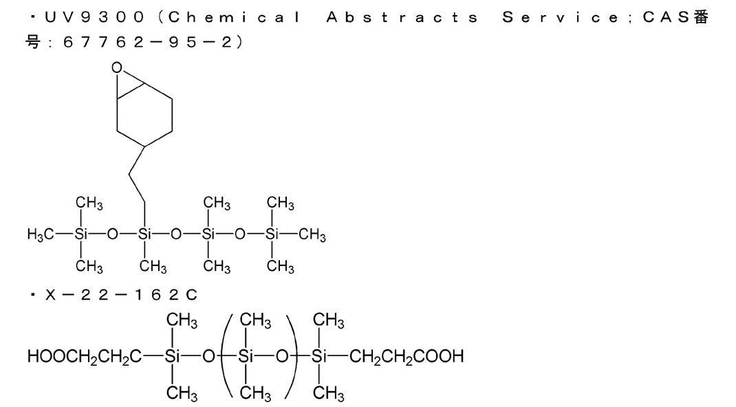
<樹脂層の作製>
(ジアルキルシロキサン基を有する放射線硬化性ポリマーの調製)
3口フラスコに市販のUV9300(Momentive社製の下記構造のポリジメチルシロキサン(PDMS)、エポキシ当量は950g/molオキシラン、粘度測定法を用いた重量平均分子量9000)39.087質量%、市販のX-22-162C(信越化学工業(株)製、下記構造の両末端カルボキシル変性シリコーン、重量平均分子量4600)10.789質量%、DBU(1,8-ジアザビシクロ[5.4.0]ウンデカ-7-エン)0.007質量%を含むn-ヘプタン溶液を調製し、95℃に維持しながら168時間経過させて、ポリ(シロキサン)基を有する放射線硬化性ポリマー溶液(25℃で粘度22.8mPa・s)を得た。
(重合性の放射線硬化性組成物の調製)
放射線硬化性ポリマー溶液は20℃まで冷却され、5質量%になるまでn-ヘプタンを添加して希釈した。得られた溶液を濾過精度2.7μmの濾紙を用いて濾過し、放射線硬化性組成物を調製した。放射線硬化性組成物に対し、光重合開始剤であるUV9380C(Momentive社製のビス(4-ドデシルフェニル)ヨードニウム-ヘキサフルオロアンチモネートの45質量%、アルキルグリシジルエーテル溶液)0.1質量%およびTi(OiPr)4(Dorf Ketal Chemicals製イソプロポキシドチタン(IV))0.1質量%添加し、重合性の放射線硬化性組成物を調製した。
放射線硬化性ポリマー溶液は20℃まで冷却され、5質量%になるまでn-ヘプタンを添加して希釈した。得られた溶液を濾過精度2.7μmの濾紙を用いて濾過し、放射線硬化性組成物を調製した。放射線硬化性組成物に対し、光重合開始剤であるUV9380C(Momentive社製のビス(4-ドデシルフェニル)ヨードニウム-ヘキサフルオロアンチモネートの45質量%、アルキルグリシジルエーテル溶液)0.1質量%およびTi(OiPr)4(Dorf Ketal Chemicals製イソプロポキシドチタン(IV))0.1質量%添加し、重合性の放射線硬化性組成物を調製した。
(重合性の放射線硬化性組成物の多孔質支持体への塗布、樹脂層の形成)
PAN(ポリアクリロニトリル)多孔質膜(不織布上にポリアクリロニトリル多孔質膜が存在、不織布を含め、厚みは約180μm)を支持体として、重合性の放射線硬化性組成物を塗布した後、UV強度24kW/m、処理時間10秒間のUV処理条件でUV処理(Fusion UV System社製、Light Hammer 10、D-バルブ)を行い、乾燥させた。このようにして、多孔質支持体上に、厚み600nmの樹脂層を形成した。
PAN(ポリアクリロニトリル)多孔質膜(不織布上にポリアクリロニトリル多孔質膜が存在、不織布を含め、厚みは約180μm)を支持体として、重合性の放射線硬化性組成物を塗布した後、UV強度24kW/m、処理時間10秒間のUV処理条件でUV処理(Fusion UV System社製、Light Hammer 10、D-バルブ)を行い、乾燥させた。このようにして、多孔質支持体上に、厚み600nmの樹脂層を形成した。
<第一の分離層の作製>
(ポリイミド(P-02)の合成)
(ポリイミド(P-02)の合成)
下記反応スキームで、ポリイミド(P-02)の合成に用いるジアミン1を合成した。
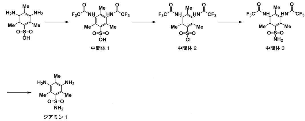
(中間体1の合成)
ジアミノメシチレンスルホン酸(和光純薬工業社製)(60g)、アセトニトリル(和光純薬工業社製)(380g)、ピリジン(和光純薬工業社製)(23g)をフラスコに入れた。氷冷下、トリフルオロ酢酸無水物(和光純薬工業社製)(115g)を慎重に滴下した後、70℃で2時間反応させた。冷却後、メタノール(和光純薬工業社製)(30g)を加え、1時間攪拌した。減圧濃縮後、塩酸を用いて精製し、中間体1(110g)を得た。
ジアミノメシチレンスルホン酸(和光純薬工業社製)(60g)、アセトニトリル(和光純薬工業社製)(380g)、ピリジン(和光純薬工業社製)(23g)をフラスコに入れた。氷冷下、トリフルオロ酢酸無水物(和光純薬工業社製)(115g)を慎重に滴下した後、70℃で2時間反応させた。冷却後、メタノール(和光純薬工業社製)(30g)を加え、1時間攪拌した。減圧濃縮後、塩酸を用いて精製し、中間体1(110g)を得た。
(中間体2の合成)
アセトニトリル(和光純薬工業社製)(440mL)、中間体1(68g)をフラスコに入れた。塩化チオニル(和光純薬工業社製)(115g)、ジメチルホルムアミド(和光純薬工業社製)(0.9g)を慎重に加えた後、発熱、発泡に注意しながら内温を70℃まで上昇させた。減圧留去後、反応混合物を氷に注いだ後、析出物を精製し、中間体2(65g)を得た。
アセトニトリル(和光純薬工業社製)(440mL)、中間体1(68g)をフラスコに入れた。塩化チオニル(和光純薬工業社製)(115g)、ジメチルホルムアミド(和光純薬工業社製)(0.9g)を慎重に加えた後、発熱、発泡に注意しながら内温を70℃まで上昇させた。減圧留去後、反応混合物を氷に注いだ後、析出物を精製し、中間体2(65g)を得た。
(中間体3の合成)
アンモニア水(和光純薬工業社製)(90g)をフラスコに入れた。氷冷下、中間体2(43g)をテトラヒドロフラン(和光純薬工業社製)(130g)に懸濁させた液を慎重に加えた。40℃で2時間攪拌した後、減圧濃縮し、精製し、中間体3(30g)を得た。
アンモニア水(和光純薬工業社製)(90g)をフラスコに入れた。氷冷下、中間体2(43g)をテトラヒドロフラン(和光純薬工業社製)(130g)に懸濁させた液を慎重に加えた。40℃で2時間攪拌した後、減圧濃縮し、精製し、中間体3(30g)を得た。
(ジアミン1の合成)
中間体3(30g)、メタノール(和光純薬工業社製)(100g)を200mLフラスコに入れた。メタンスルホン酸(和光純薬工業社製)(30g)を慎重に加え、発熱に注意しながら昇温し、120℃で30分間攪拌した。冷却した後、反応溶液を炭酸カリウム溶液に注いだ後、析出物を精製し、ジアミン1(11g)を得た。
中間体3(30g)、メタノール(和光純薬工業社製)(100g)を200mLフラスコに入れた。メタンスルホン酸(和光純薬工業社製)(30g)を慎重に加え、発熱に注意しながら昇温し、120℃で30分間攪拌した。冷却した後、反応溶液を炭酸カリウム溶液に注いだ後、析出物を精製し、ジアミン1(11g)を得た。
(ポリイミド(P-02)の合成)
メタクレゾール(和光純薬工業社製)(100g)、ジアミン1(9.00g)、3,5-ジアミノ安息香酸(東京化成工業社製)(0.66g)、6FDA(東京化成工業社製)(19.37g)をフラスコに入れた。トルエン(和光純薬工業社製)(10g)、イソキノリン(和光純薬工業社製)(1.5g)を加えた後、180℃まで加熱し、6時間反応させた。冷却後、アセトン(和光純薬工業社製)で希釈した後、イソプロピルアルコール(和光純薬工業社製)を加えてポリマーを固体として得た。同様の再沈殿を2回繰り返した後、80℃で乾燥し、ポリイミド(P-02)(22g)を得た。
下記表3~5中、ポリイミド(P-02)のことを、PI(P-02)と省略して記載した。
メタクレゾール(和光純薬工業社製)(100g)、ジアミン1(9.00g)、3,5-ジアミノ安息香酸(東京化成工業社製)(0.66g)、6FDA(東京化成工業社製)(19.37g)をフラスコに入れた。トルエン(和光純薬工業社製)(10g)、イソキノリン(和光純薬工業社製)(1.5g)を加えた後、180℃まで加熱し、6時間反応させた。冷却後、アセトン(和光純薬工業社製)で希釈した後、イソプロピルアルコール(和光純薬工業社製)を加えてポリマーを固体として得た。同様の再沈殿を2回繰り返した後、80℃で乾燥し、ポリイミド(P-02)(22g)を得た。
下記表3~5中、ポリイミド(P-02)のことを、PI(P-02)と省略して記載した。
ポリイミド(P-02)

(第一の分離層の形成)
多孔質支持体上に厚み600nmの樹脂層を形成した積層体に対し、樹脂層上に酸素流量50cm3(STP)/分、アルゴン流量100cm3(STP)/分、放電出力10Wのプラズマ処理条件で5秒間プラズマ処理を行った。
褐色バイアル瓶に、反応性基を有するポリイミド(P-02)を1.4g、メチルエチルケトンを8.6g混合して、25℃で30分間攪拌し、第一の分離層形成用の溶液とした。
その後、攪拌した第一の分離層形成用の溶液を樹脂層のプラズマ処理面上に塗布し、乾燥し、厚み70nmの第一の分離層を形成した。
多孔質支持体上に厚み600nmの樹脂層を形成した積層体に対し、樹脂層上に酸素流量50cm3(STP)/分、アルゴン流量100cm3(STP)/分、放電出力10Wのプラズマ処理条件で5秒間プラズマ処理を行った。
褐色バイアル瓶に、反応性基を有するポリイミド(P-02)を1.4g、メチルエチルケトンを8.6g混合して、25℃で30分間攪拌し、第一の分離層形成用の溶液とした。
その後、攪拌した第一の分離層形成用の溶液を樹脂層のプラズマ処理面上に塗布し、乾燥し、厚み70nmの第一の分離層を形成した。
(第一の分離層のSi/C比)
第二の分離層側の第一の分離層の界面(第二の分離層が存在しない場合は、樹脂層と接する側とは反対側の表面)におけるケイ素原子の数の炭素原子の数に対する比であるSi/C比を、ESCA(Electron Spectroscopy FOR Chemical Analysis)を使用して算出した。
第一の分離層のSi/C比は、後述の第二の分離層のSi/C比と同様の方法で算出した。その結果、第一の分離層のSi/C比は0であった。
第二の分離層側の第一の分離層の界面(第二の分離層が存在しない場合は、樹脂層と接する側とは反対側の表面)におけるケイ素原子の数の炭素原子の数に対する比であるSi/C比を、ESCA(Electron Spectroscopy FOR Chemical Analysis)を使用して算出した。
第一の分離層のSi/C比は、後述の第二の分離層のSi/C比と同様の方法で算出した。その結果、第一の分離層のSi/C比は0であった。
<保護層の形成>
その後、樹脂層の形成に用いた重合性の放射線硬化性組成物を、第一の分離層の上に塗布後、樹脂層の形成と同様のUV処理条件でUV処理を行うことで、第一の分離層上に厚み600nmの保護層を形成し、50℃で乾燥させた。
得られたガス分離膜を、比較例1のガス分離膜とした。
その後、樹脂層の形成に用いた重合性の放射線硬化性組成物を、第一の分離層の上に塗布後、樹脂層の形成と同様のUV処理条件でUV処理を行うことで、第一の分離層上に厚み600nmの保護層を形成し、50℃で乾燥させた。
得られたガス分離膜を、比較例1のガス分離膜とした。
[比較例2]
<第二の分離層の形成>
トルエン中に1質量%の濃度になるようにpoly[(l-trimethylsilyl)-l-propyne](PTMSP)(GELEST, SSP-070)を溶解させ、第二の分離層の形成用の組成物(1)を調製した。
比較例1で得られた第一の分離層の上に、第二の分離層の形成用の組成物(1)を塗布し、乾燥して、80nmの第二の分離層を積層した。
<第二の分離層の形成>
トルエン中に1質量%の濃度になるようにpoly[(l-trimethylsilyl)-l-propyne](PTMSP)(GELEST, SSP-070)を溶解させ、第二の分離層の形成用の組成物(1)を調製した。
比較例1で得られた第一の分離層の上に、第二の分離層の形成用の組成物(1)を塗布し、乾燥して、80nmの第二の分離層を積層した。
<保護層の形成>
その後、比較例1において樹脂層の形成に用いた重合性の放射線硬化性組成物を、第二の分離層の上に塗布後、樹脂層の形成と同様のUV処理条件でUV処理を行うことで、第二の分離層上に厚み600nmの保護層を形成し、50℃で乾燥させた。
得られたガス分離膜を、比較例2のガス分離膜とした。
その後、比較例1において樹脂層の形成に用いた重合性の放射線硬化性組成物を、第二の分離層の上に塗布後、樹脂層の形成と同様のUV処理条件でUV処理を行うことで、第二の分離層上に厚み600nmの保護層を形成し、50℃で乾燥させた。
得られたガス分離膜を、比較例2のガス分離膜とした。
[実施例1]
<第二の分離層の形成>
LINC-3A(共栄社化学株式会社、トリアクリロイルヘプタデカフルオロノネニルペンタエリスリトールであるフルオロ(メタ)アクリレート)と、重合開始剤IRGACURE 127(BASF製、Irg127と略す)を、LINC-3Aに対して重合開始剤が固形分濃度3質量%となるようにヘプタンとブタノールの比が9:1の溶剤に溶解させ、第二の分離層の形成用の組成物(2)を調製した。
比較例1で得られた第一の分離層の上に、第二の分離層の形成用の組成物(2)を、第二の分離層の厚みが20nmとなるように塗布した。
その後、第二の分離層の形成用の組成物(2)を、以下の条件で架橋反応させて、20nmの第二の分離層を積層した。
UV-A(ultraviolet A;400~320nmの紫外線)が0.23J/cm2となる条件でUV処理(Fusion UV System社製、Light Hammer 10、H-バルブ)を行い、乾燥させた。
<第二の分離層の形成>
LINC-3A(共栄社化学株式会社、トリアクリロイルヘプタデカフルオロノネニルペンタエリスリトールであるフルオロ(メタ)アクリレート)と、重合開始剤IRGACURE 127(BASF製、Irg127と略す)を、LINC-3Aに対して重合開始剤が固形分濃度3質量%となるようにヘプタンとブタノールの比が9:1の溶剤に溶解させ、第二の分離層の形成用の組成物(2)を調製した。
比較例1で得られた第一の分離層の上に、第二の分離層の形成用の組成物(2)を、第二の分離層の厚みが20nmとなるように塗布した。
その後、第二の分離層の形成用の組成物(2)を、以下の条件で架橋反応させて、20nmの第二の分離層を積層した。
UV-A(ultraviolet A;400~320nmの紫外線)が0.23J/cm2となる条件でUV処理(Fusion UV System社製、Light Hammer 10、H-バルブ)を行い、乾燥させた。
<保護層の形成>
その後、比較例1において樹脂層の形成に用いた重合性の放射線硬化性組成物を、第二の分離層の上に塗布後、樹脂層の形成と同様のUV処理条件でUV処理を行うことで、第二の分離層上に厚み600nmの保護層を形成し、50℃で乾燥させた。
得られた多孔質支持体と、樹脂層と、第一の分離層と、第二の分離層と、保護層とを有する複合膜を、実施例1のガス分離膜とした。
その後、比較例1において樹脂層の形成に用いた重合性の放射線硬化性組成物を、第二の分離層の上に塗布後、樹脂層の形成と同様のUV処理条件でUV処理を行うことで、第二の分離層上に厚み600nmの保護層を形成し、50℃で乾燥させた。
得られた多孔質支持体と、樹脂層と、第一の分離層と、第二の分離層と、保護層とを有する複合膜を、実施例1のガス分離膜とした。
<第二の分離層の厚み、F/C比、Si/C比>
得られたガス分離膜の中心をサンプリングし、フッ素原子の数の炭素原子の数に対する比であるF/C比の最大値を、ESCA(Electron Spectroscopy FOR Chemical Analysis)を使用して算出した。同様に、F/C比が最大値をとる部分におけるSi/C比も、ESCAを使用して算出した。
支持体と、樹脂層と、第一の分離層と、第二の分離層と、保護層を有するガス分離膜をPhysical Electronics, Inc.社製 QuanteraSXMであるESCA装置にサンプルを入れた。X線源:Al-Kα線(1490eV,25W,100μmの直径)、測定領域:300μm×300μm、Pass Energy 55eV、 Step 0.05eVの条件で、第二の分離層のF/C比と、Si/C比を算出した。
第二の分離層の厚み、ならびに、第二の分離層の厚み方向の各部分におけるF/C比およびSi/C比を求めるためにC60イオンを用いたエッチングを行った。すなわち、Physical Electronics, Inc.社製 QuanteraSXM付属C60イオン銃にて、イオンビーム強度はC60 +:10keV、10nAとし、2mm×2mmの領域をサンプルの第一の分離層と反対側の表面から第二の分離層の内部方向へエッチングした。
第一の分離層を有さないサンプルについては、サンプルの支持体と反対側の表面から第二の分離層の内部方向へエッチングした。ESCA装置を用いて、フッ素原子の数の炭素原子の数に対する比であるF/C比が最大値をとる部分(最大となる面)を算出した。
「第一の分離層とは反対側の第二の分離層の界面」から、「第一の分離層側の第二の分離層の界面」までの距離(深さ)を、第二の分離層の厚みとした。第二の分離層の厚み方向の距離は、第二の分離層材料のエッチング速度10nm/分から算出した。この値は材質が変わるごとに求めることが出来、適宜材料に最適な数値を用いるものとする。
ただし、実施例8では、第二の分離層の上側を「第一の分離層とは反対側の第二の分離層の表面」とした。
得られたガス分離膜の中心をサンプリングし、フッ素原子の数の炭素原子の数に対する比であるF/C比の最大値を、ESCA(Electron Spectroscopy FOR Chemical Analysis)を使用して算出した。同様に、F/C比が最大値をとる部分におけるSi/C比も、ESCAを使用して算出した。
支持体と、樹脂層と、第一の分離層と、第二の分離層と、保護層を有するガス分離膜をPhysical Electronics, Inc.社製 QuanteraSXMであるESCA装置にサンプルを入れた。X線源:Al-Kα線(1490eV,25W,100μmの直径)、測定領域:300μm×300μm、Pass Energy 55eV、 Step 0.05eVの条件で、第二の分離層のF/C比と、Si/C比を算出した。
第二の分離層の厚み、ならびに、第二の分離層の厚み方向の各部分におけるF/C比およびSi/C比を求めるためにC60イオンを用いたエッチングを行った。すなわち、Physical Electronics, Inc.社製 QuanteraSXM付属C60イオン銃にて、イオンビーム強度はC60 +:10keV、10nAとし、2mm×2mmの領域をサンプルの第一の分離層と反対側の表面から第二の分離層の内部方向へエッチングした。
第一の分離層を有さないサンプルについては、サンプルの支持体と反対側の表面から第二の分離層の内部方向へエッチングした。ESCA装置を用いて、フッ素原子の数の炭素原子の数に対する比であるF/C比が最大値をとる部分(最大となる面)を算出した。
「第一の分離層とは反対側の第二の分離層の界面」から、「第一の分離層側の第二の分離層の界面」までの距離(深さ)を、第二の分離層の厚みとした。第二の分離層の厚み方向の距離は、第二の分離層材料のエッチング速度10nm/分から算出した。この値は材質が変わるごとに求めることが出来、適宜材料に最適な数値を用いるものとする。
ただし、実施例8では、第二の分離層の上側を「第一の分離層とは反対側の第二の分離層の表面」とした。
<第二の分離層の自由体積径>
(第三成分の陽電子寿命の測定)
1.5cm×1.5cm角の試験片を得られたガス分離膜から切り出し、ESCAを用いたエッチングを用い、第二の分離層との界面が出るまで保護層をエッチングする条件を算出し、同条件でエッチングを行ったサンプルを調製した。
得られたサンプルを市販のSiウェハに貼り付けて、室温(25℃)で真空脱気した後に、下記表1の条件で第三成分の陽電子消滅寿命の測定を行った。下記表1の条件であれば、第三成分の陽電子寿命は一義的に定まる。

得られたデータを非線形最小二乗プログラムPOSITRONFITに基づき、第三成分の解析を行い、第三成分の陽電子寿命τ3(ns)を、ビーム強度1keVに関して計算した(P. Kirkegaard, M. Eldrup, O. E. Mogensen, N. J. Pedersen,Computer Physics Communications, 23, 307 (1981))。
第三成分の陽電子寿命τ3から、第二の分離層の自由体積径(第二の分離層の空孔の直径)を、半経験式:S. T. Tao, J. Chem. Phys., 56, 5499 (1972))に基づいて計算した。
得られた第二の分離層の自由体積径を下記表3~5に記載した。
(第三成分の陽電子寿命の測定)
1.5cm×1.5cm角の試験片を得られたガス分離膜から切り出し、ESCAを用いたエッチングを用い、第二の分離層との界面が出るまで保護層をエッチングする条件を算出し、同条件でエッチングを行ったサンプルを調製した。
得られたサンプルを市販のSiウェハに貼り付けて、室温(25℃)で真空脱気した後に、下記表1の条件で第三成分の陽電子消滅寿命の測定を行った。下記表1の条件であれば、第三成分の陽電子寿命は一義的に定まる。
得られたデータを非線形最小二乗プログラムPOSITRONFITに基づき、第三成分の解析を行い、第三成分の陽電子寿命τ3(ns)を、ビーム強度1keVに関して計算した(P. Kirkegaard, M. Eldrup, O. E. Mogensen, N. J. Pedersen,Computer Physics Communications, 23, 307 (1981))。
第三成分の陽電子寿命τ3から、第二の分離層の自由体積径(第二の分離層の空孔の直径)を、半経験式:S. T. Tao, J. Chem. Phys., 56, 5499 (1972))に基づいて計算した。
得られた第二の分離層の自由体積径を下記表3~5に記載した。
<第二の分離層の有機溶剤への不溶性>
各実施例および比較例のガス分離膜について、凍結活断により断面を出した試料片を調製した。
トルエン、ヘプタンからなる溶剤に1日間浸漬する前の試験片について、エッチングとESCAを交互に行い、第二の分離層のF/C比を測定した。また、第二の分離層のF/C比が最大値をとる部分における、蛍光X線分析(X-ray Fluorescence、XRF)におけるフッ素原子のXRF強度を、エッチングとESCAを交互に用いて、表面を出して測定した。
試料片を、組成比が質量比で1:1であるトルエンおよびヘプタンからなる有機溶剤に1日間浸漬した。その後、エッチングとESCAを交互に行い、第二の分離層のF/C比を測定した。また、第二の分離層のF/C比が最大値をとる部分における、蛍光X線分析におけるフッ素原子のXRF強度を、エッチングとESCAを交互に行い、表面を出して測定した。
第二の分離層の蛍光X線分析におけるフッ素原子のXRF強度は、以下の方法で測定した。
本発明におけるXRF強度は、以下の方法で測定した値のことを表す。
蛍光X線分析装置(XRF;X-ray FluorescenceSpectrometer)を用いて、検量線法によりF原子の量(F mg/m2)を測定する。蛍光X線分析装置の機種としては特に限定はないが、本発明においては、理学電機工業(株)製RIX3000を用い下記条件におけるF原子の量を採用している。
装置 :理学電機工業(株)製RIX3000
X線管球 :Rh管電圧 :50kV管電流 :50mAスリット :COARSE分光結晶 :RX4検出器 :F-PC分析面積 :直径30mmバックグランド(2θ):140.70deg.、146.85deg.積算時間 :80秒/sample
第二の分離層の有機溶剤への不溶性を、F/C比の最大値の変動および蛍光X線分析におけるフッ素原子のXRF強度の変動の測定結果を用いて、以下の基準に基づいて評価した。
A:有機溶剤に不溶
(組成比が質量比で1:1であるトルエンおよびヘプタンからなる有機溶剤に1日間浸漬した前後の、F/C比の最大値の変動および、F/C比が最大値をとる部分における蛍光X線分析におけるフッ素原子のXRF強度の変動がいずれも30%未満)。
C:有機溶剤に可溶
(組成比が質量比で1:1であるトルエンおよびヘプタンからなる有機溶剤に1日間浸漬した前後の、F/C比の最大値の変動および、F/C比が最大値をとる部分における蛍光X線分析におけるフッ素原子のXRF強度の変動のうち少なくとも一方が30%以上)。
得られた結果を下記表3~5に記載した。なお、トルエンからなる有機溶剤、ヘプタンからなる有機溶剤、メチルエチルケトンからなる有機溶剤の3種類についても、第二の分離層の有機溶剤への不溶性を同様に評価したところ、組成比が質量比で1:1であるトルエンおよびヘプタンからなる有機溶剤を用いた場合の評価結果と同様であった。
各実施例および比較例のガス分離膜について、凍結活断により断面を出した試料片を調製した。
トルエン、ヘプタンからなる溶剤に1日間浸漬する前の試験片について、エッチングとESCAを交互に行い、第二の分離層のF/C比を測定した。また、第二の分離層のF/C比が最大値をとる部分における、蛍光X線分析(X-ray Fluorescence、XRF)におけるフッ素原子のXRF強度を、エッチングとESCAを交互に用いて、表面を出して測定した。
試料片を、組成比が質量比で1:1であるトルエンおよびヘプタンからなる有機溶剤に1日間浸漬した。その後、エッチングとESCAを交互に行い、第二の分離層のF/C比を測定した。また、第二の分離層のF/C比が最大値をとる部分における、蛍光X線分析におけるフッ素原子のXRF強度を、エッチングとESCAを交互に行い、表面を出して測定した。
第二の分離層の蛍光X線分析におけるフッ素原子のXRF強度は、以下の方法で測定した。
本発明におけるXRF強度は、以下の方法で測定した値のことを表す。
蛍光X線分析装置(XRF;X-ray FluorescenceSpectrometer)を用いて、検量線法によりF原子の量(F mg/m2)を測定する。蛍光X線分析装置の機種としては特に限定はないが、本発明においては、理学電機工業(株)製RIX3000を用い下記条件におけるF原子の量を採用している。
装置 :理学電機工業(株)製RIX3000
X線管球 :Rh管電圧 :50kV管電流 :50mAスリット :COARSE分光結晶 :RX4検出器 :F-PC分析面積 :直径30mmバックグランド(2θ):140.70deg.、146.85deg.積算時間 :80秒/sample
第二の分離層の有機溶剤への不溶性を、F/C比の最大値の変動および蛍光X線分析におけるフッ素原子のXRF強度の変動の測定結果を用いて、以下の基準に基づいて評価した。
A:有機溶剤に不溶
(組成比が質量比で1:1であるトルエンおよびヘプタンからなる有機溶剤に1日間浸漬した前後の、F/C比の最大値の変動および、F/C比が最大値をとる部分における蛍光X線分析におけるフッ素原子のXRF強度の変動がいずれも30%未満)。
C:有機溶剤に可溶
(組成比が質量比で1:1であるトルエンおよびヘプタンからなる有機溶剤に1日間浸漬した前後の、F/C比の最大値の変動および、F/C比が最大値をとる部分における蛍光X線分析におけるフッ素原子のXRF強度の変動のうち少なくとも一方が30%以上)。
得られた結果を下記表3~5に記載した。なお、トルエンからなる有機溶剤、ヘプタンからなる有機溶剤、メチルエチルケトンからなる有機溶剤の3種類についても、第二の分離層の有機溶剤への不溶性を同様に評価したところ、組成比が質量比で1:1であるトルエンおよびヘプタンからなる有機溶剤を用いた場合の評価結果と同様であった。
[実施例2~15、比較例6および7]
実施例1において、第二の分離層の樹脂またはモノマー、重合開始剤の種類と固形分濃度、第二の分離層の厚みを下記表3~5のとおり変更した以外は実施例1と同様にして、各実施例および比較例のガス分離膜を製造した。
ただし、重合開始剤を用いなかった実施例8および13では、架橋反応も行わなかった。
実施例1において、第二の分離層の樹脂またはモノマー、重合開始剤の種類と固形分濃度、第二の分離層の厚みを下記表3~5のとおり変更した以外は実施例1と同様にして、各実施例および比較例のガス分離膜を製造した。
ただし、重合開始剤を用いなかった実施例8および13では、架橋反応も行わなかった。
<第二の分離層の樹脂またはモノマー>
二官能F(1,6-Bis(acryloyloxy)-2,2,3,3,4,4,5,5-octafluorohexane(CAS番号:2264-01-9 製品コード:B2340)、東京化成工業株式会社製、フルオロ(メタ)アクリレートモノマー)
サイトップ(商品名サイトップCTL-809M、旭硝子製、フルオロオレフィンの重合体)
フルオネート(商品名フルオネート K-704、DIC製、水酸基含有のフルオロオレフィンの重合体)
FM7721(商品名サイラプレーンFM-7721、JNC製、シリコーンアクリレート系モノマー)
なお、下記表6中、Linc-3A(80)/FM7721(20)は、80質量%のLinc-3Aおよび20質量%のFM7721を併用したことを意味する。Linc-3A(50)/FM7721(50)は、50質量%のLinc-3Aおよび50質量%のFM7721を併用したことを意味する。Linc-3A(20)/FM7721(80)は、20質量%のLinc-3Aおよび80質量%のFM7721を併用したことを意味する。
二官能F(1,6-Bis(acryloyloxy)-2,2,3,3,4,4,5,5-octafluorohexane(CAS番号:2264-01-9 製品コード:B2340)、東京化成工業株式会社製、フルオロ(メタ)アクリレートモノマー)
サイトップ(商品名サイトップCTL-809M、旭硝子製、フルオロオレフィンの重合体)
フルオネート(商品名フルオネート K-704、DIC製、水酸基含有のフルオロオレフィンの重合体)
FM7721(商品名サイラプレーンFM-7721、JNC製、シリコーンアクリレート系モノマー)
なお、下記表6中、Linc-3A(80)/FM7721(20)は、80質量%のLinc-3Aおよび20質量%のFM7721を併用したことを意味する。Linc-3A(50)/FM7721(50)は、50質量%のLinc-3Aおよび50質量%のFM7721を併用したことを意味する。Linc-3A(20)/FM7721(80)は、20質量%のLinc-3Aおよび80質量%のFM7721を併用したことを意味する。
<第二の分離層の重合開始剤>
バーノックDN-980(ポリイソシアネートプレポリマー:固形分=75質量%、DIC製、硬化剤とも言われる)
バーノックDN-980(ポリイソシアネートプレポリマー:固形分=75質量%、DIC製、硬化剤とも言われる)
[比較例3]
比較例1で作製した多孔質支持体上に厚み600nmの樹脂層を形成した積層体に対し、比較例1と同様にして樹脂層をプラズマ処理した。
その後、樹脂層のプラズマ処理面上に、実施例1で調製した第二の分離層の形成用の組成物(2)を、第二の分離層の厚みが40nmとなるように塗布した。
その後、第二の分離層の形成用の組成物(2)を、実施例1と同様の条件で架橋反応させて、40nmの厚みの第二の分離層を形成した。
その後、実施例1と同様にして第二の分離層上に保護層を形成した。
得られた多孔質支持体と、樹脂層と、第二の分離層と、保護層とを有する複合膜を、比較例3のガス分離膜とした。
比較例1で作製した多孔質支持体上に厚み600nmの樹脂層を形成した積層体に対し、比較例1と同様にして樹脂層をプラズマ処理した。
その後、樹脂層のプラズマ処理面上に、実施例1で調製した第二の分離層の形成用の組成物(2)を、第二の分離層の厚みが40nmとなるように塗布した。
その後、第二の分離層の形成用の組成物(2)を、実施例1と同様の条件で架橋反応させて、40nmの厚みの第二の分離層を形成した。
その後、実施例1と同様にして第二の分離層上に保護層を形成した。
得られた多孔質支持体と、樹脂層と、第二の分離層と、保護層とを有する複合膜を、比較例3のガス分離膜とした。
[比較例4および5]
比較例3において、第二の分離層の樹脂またはモノマー、重合開始剤、第二の分離層の厚みを下記表4のとおり変更した以外は比較例3と同様にして、比較例4および5のガス分離膜を製造した。
ただし、重合開始剤を用いなかった比較例4および5では、架橋反応も行わなかった。
比較例3において、第二の分離層の樹脂またはモノマー、重合開始剤、第二の分離層の厚みを下記表4のとおり変更した以外は比較例3と同様にして、比較例4および5のガス分離膜を製造した。
ただし、重合開始剤を用いなかった比較例4および5では、架橋反応も行わなかった。
[実施例16]
比較例1で調製した第一の分離層形成用の溶液に対し、フッ素含有界面活性剤メガファックRS-75(DIC製)を、ポリイミドである反応性基を有するポリイミド(P-02)に対し10質量%になるように添加し、第一の分離層形成用の溶液(A)を調製した。
第一の分離層形成用の溶液(A)を用いた以外は比較例1と同様にして、攪拌した第一の分離層形成用の溶液(A)を樹脂層のプラズマ処理面上に塗布し、乾燥した。その結果、第一の分離層と第二の分離層(フッ素含有界面活性剤が偏在して形成された層)が同時に形成された。
その後、比較例2と同様にして、第二の分離層の上に保護層を形成した。
得られたガス分離膜を、実施例16のガス分離膜とした。
比較例1で調製した第一の分離層形成用の溶液に対し、フッ素含有界面活性剤メガファックRS-75(DIC製)を、ポリイミドである反応性基を有するポリイミド(P-02)に対し10質量%になるように添加し、第一の分離層形成用の溶液(A)を調製した。
第一の分離層形成用の溶液(A)を用いた以外は比較例1と同様にして、攪拌した第一の分離層形成用の溶液(A)を樹脂層のプラズマ処理面上に塗布し、乾燥した。その結果、第一の分離層と第二の分離層(フッ素含有界面活性剤が偏在して形成された層)が同時に形成された。
その後、比較例2と同様にして、第二の分離層の上に保護層を形成した。
得られたガス分離膜を、実施例16のガス分離膜とした。
[比較例8および実施例17~20]
第一の分離層に用いた樹脂をポリイミド(P-02)から以下のポリイミド(P-101)に変更した以外は比較例1、実施例2、3、11および12とそれぞれ同様にして、比較例8および実施例17~20のガス分離膜を製造した。
第一の分離層に用いた樹脂をポリイミド(P-02)から以下のポリイミド(P-101)に変更した以外は比較例1、実施例2、3、11および12とそれぞれ同様にして、比較例8および実施例17~20のガス分離膜を製造した。
<第一の分離層の作製>
(ポリイミド(P-101)の合成)
下記反応スキームでポリイミド(P-101)を合成した。

(ポリイミド(P-101)の合成)
下記反応スキームでポリイミド(P-101)を合成した。
3口フラスコにN-メチルピロリドン123ml、6FDA(東京化成株式会社製、4,4’-(ヘキサフルオロイソプロピリデン)ジフタル酸無水物)54.97g(0.124mol)を加えて40℃で溶解させ、窒素気流下で攪拌しているところに、2,3,5,6-テトラメチルフェニレンジアミン(東京化成株式会社製、製品番号:T1457)4.098g(0.0248mol)、3,5-ジアミノ安息香酸15.138g(0.0992mol)のN-メチルピロリドン84.0ml溶液を30分間かけて系内を40℃に保ちつつ滴下した。反応液を40℃で2.5時間攪拌した後、ピリジン(和光純薬株式会社製)2.94g(0.037mol)、無水酢酸(和光純薬株式会社製)31.58g(0.31mol)をそれぞれ加えて、さらに80℃で3時間攪拌した。その後、反応液にアセトン676.6mLを加え、希釈した。ステンレス容器にメタノール1.15L、アセトン230mLを加えて攪拌しているところに、反応液のアセトン希釈液を滴下した。得られたポリマー結晶を吸引ろ過し、60℃で送風乾燥させて50.5gのポリイミド(P-101)を得た。下記表5中、ポリイミド(P-101)のことを、PI(P-101)と省略して記載した。
[評価]
<ガス分離選択性>
各実施例および比較例のガス分離膜において、高圧耐性のあるSUS316製ステンレスセル(DENISSEN社製)を用い、セルの温度が30℃となるよう調整して、ガス分離選択性を評価した。二酸化炭素(CO2)、メタン(CH4)の体積比が6:94の混合ガスをガス供給側の全圧力が5MPa(CO2の分圧:0.65MPa)となるように調整し、CO2、CH4のそれぞれのガスの透過性をTCD検知式ガスクロマトグラフィーにより測定した。各実施例および比較例のガス分離膜のガス分離選択性(CO2/CH4ガス分離選択性)は、この膜のCH4の透過係数PCH4に対するCO2の透過係数PCO2の割合(PCO2/PCH4)として計算した。各実施例および比較例のガス分離膜のCO2透過性は、この膜のCO2の透過度QCO2(単位:GPU)とした。
なお、ガス透過性の単位は、圧力差あたりの透過流束(透過率、透過度、Permeanceとも言う)を表すGPU(ジーピーユー)単位〔1GPU=1×10⁻⁶cm3(STP)/cm2・sec・cmHg〕または透過係数を表すbarrer(バーラー)単位〔1barrer=1×10-10cm3(STP)・cm/cm2・sec・cmHg〕
で表す。本明細書中では、GPU単位の場合は記号Qを用いて表し、barrer単位の場合は記号Pを用いて表した。
<ガス分離選択性>
各実施例および比較例のガス分離膜において、高圧耐性のあるSUS316製ステンレスセル(DENISSEN社製)を用い、セルの温度が30℃となるよう調整して、ガス分離選択性を評価した。二酸化炭素(CO2)、メタン(CH4)の体積比が6:94の混合ガスをガス供給側の全圧力が5MPa(CO2の分圧:0.65MPa)となるように調整し、CO2、CH4のそれぞれのガスの透過性をTCD検知式ガスクロマトグラフィーにより測定した。各実施例および比較例のガス分離膜のガス分離選択性(CO2/CH4ガス分離選択性)は、この膜のCH4の透過係数PCH4に対するCO2の透過係数PCO2の割合(PCO2/PCH4)として計算した。各実施例および比較例のガス分離膜のCO2透過性は、この膜のCO2の透過度QCO2(単位:GPU)とした。
なお、ガス透過性の単位は、圧力差あたりの透過流束(透過率、透過度、Permeanceとも言う)を表すGPU(ジーピーユー)単位〔1GPU=1×10⁻⁶cm3(STP)/cm2・sec・cmHg〕または透過係数を表すbarrer(バーラー)単位〔1barrer=1×10-10cm3(STP)・cm/cm2・sec・cmHg〕
で表す。本明細書中では、GPU単位の場合は記号Qを用いて表し、barrer単位の場合は記号Pを用いて表した。
A:比較例1に対して、CO2分離選択性が上昇
B:比較例1に対して、CO2分離選択性が同じまたはCO2分離選択性の低下が20%未満
D:比較例1に対して、CO2分離選択性の低下が20%以上
得られた結果を、下記表3~5に記載した。
B:比較例1に対して、CO2分離選択性が同じまたはCO2分離選択性の低下が20%未満
D:比較例1に対して、CO2分離選択性の低下が20%以上
得られた結果を、下記表3~5に記載した。
<不純物ガス暴露後のガス分離選択性低下>
各実施例および比較例のガス分離膜10を、支持体側をアルミ板21の側にして四方をカプトンテープ22(寺岡製作所650S♯25)で貼り付け、図3に示すように支持体側がトルエン蒸気に暴露されないように封止したサンプルを調製した。その後25℃において、トルエン飽和蒸気で満たした密閉容器の中にサンプルを入れ、4時間放置し、ガス分離膜をトルエン膨潤した。
その後、アルミ板21よりガス分離膜10を剥がし、30分間以内にガス分離選択性の試験を行った。
トルエン膨潤後の結果を、トルエン膨潤を行わずにガス分離選択性の試験を行った別の試験片の結果と比較し、以下の基準で評価した。
A:トルエン膨潤後のガス分離選択性の低下率が30%未満
B:トルエン膨潤後のガス分離選択性の低下率が30%以上70%未満
D:トルエン膨潤後のガス分離選択性の低下率が70%以上
得られた不純物ガス暴露後のガス分離選択性低下(トルエン膨潤後の選択性低下)の結果を、下記表3~5に記載した。
各実施例および比較例のガス分離膜10を、支持体側をアルミ板21の側にして四方をカプトンテープ22(寺岡製作所650S♯25)で貼り付け、図3に示すように支持体側がトルエン蒸気に暴露されないように封止したサンプルを調製した。その後25℃において、トルエン飽和蒸気で満たした密閉容器の中にサンプルを入れ、4時間放置し、ガス分離膜をトルエン膨潤した。
その後、アルミ板21よりガス分離膜10を剥がし、30分間以内にガス分離選択性の試験を行った。
トルエン膨潤後の結果を、トルエン膨潤を行わずにガス分離選択性の試験を行った別の試験片の結果と比較し、以下の基準で評価した。
A:トルエン膨潤後のガス分離選択性の低下率が30%未満
B:トルエン膨潤後のガス分離選択性の低下率が30%以上70%未満
D:トルエン膨潤後のガス分離選択性の低下率が70%以上
得られた不純物ガス暴露後のガス分離選択性低下(トルエン膨潤後の選択性低下)の結果を、下記表3~5に記載した。
<ガス透過性>
ガス分離選択性の評価において測定したCO2透過性の結果に基づいて、各実施例および比較例のガス分離膜のガス透過性を以下の基準で評価した。
A:比較例1に対して、CO2透過性の低下が20%未満
B:比較例1に対して、CO2透過性の低下が20%以上50%未満
C:比較例1に対して、CO2透過性の低下が50%以上
得られた結果を、下記表3~5に記載した。
ガス分離選択性の評価において測定したCO2透過性の結果に基づいて、各実施例および比較例のガス分離膜のガス透過性を以下の基準で評価した。
A:比較例1に対して、CO2透過性の低下が20%未満
B:比較例1に対して、CO2透過性の低下が20%以上50%未満
C:比較例1に対して、CO2透過性の低下が50%以上
得られた結果を、下記表3~5に記載した。
<耐擦性>
各実施例および比較例のガス分離膜に対し、以下の方法で耐擦性の試験を行い、以下の基準で評価した。
5cm角のサンプルの上にベンコットをのせ、その上に300gの重りをのせ、ベンコットを引っ張り、サンプル上を移動させる操作を擦り一回とした。
A:ベンコット(旭化成製、商品名はベンコットM-1)を用いた擦り10回以上で欠陥発生せず
B:ベンコットを用いた擦り3回で欠陥発生せず、4~9回で欠陥発生
C:ベンコットを用いた擦り3回以下で欠陥発生
なお、本試験における欠陥とは、ガス選択性の評価時に圧力が5MPaまで上昇せず圧が保てなくなる事を言う。
得られた結果を、下記表3~5に記載した。
各実施例および比較例のガス分離膜に対し、以下の方法で耐擦性の試験を行い、以下の基準で評価した。
5cm角のサンプルの上にベンコットをのせ、その上に300gの重りをのせ、ベンコットを引っ張り、サンプル上を移動させる操作を擦り一回とした。
A:ベンコット(旭化成製、商品名はベンコットM-1)を用いた擦り10回以上で欠陥発生せず
B:ベンコットを用いた擦り3回で欠陥発生せず、4~9回で欠陥発生
C:ベンコットを用いた擦り3回以下で欠陥発生
なお、本試験における欠陥とは、ガス選択性の評価時に圧力が5MPaまで上昇せず圧が保てなくなる事を言う。
得られた結果を、下記表3~5に記載した。
<経時後の高次炭化水素ガス選択性>
ガス分離選択性の評価と同様に各実施例および比較例のガス分離膜をガス透過試験機にセットし、1日間、下記表2に記載のガス組成のガスを流した。
ガス分離選択性の評価と同様に各実施例および比較例のガス分離膜をガス透過試験機にセットし、1日間、下記表2に記載のガス組成のガスを流した。

その後、各成分のガス透過性を石鹸膜流量計、およびガス分離選択性の評価と同様のガスクロマトグラフィーを使用して計測した。
CO2/C3ガス分離選択性は、この膜のC3(プロパン)の透過係数PC3に対するCO2の透過係数PCO2の割合(PCO2/PC3)として計算した。
CO2/C4ガス分離選択性は、この膜のC4(n-ブタンおよびイソブタンの合計)の透過係数PC4に対するCO2の透過係数PCO2の割合(PCO2/PC4)として計算した。
CO2/C3ガス分離選択性およびCO2/C4ガス分離選択性の結果に基づいて、以下の基準で経時後の高次炭化水素ガス分離選択性を評価した。
A:比較例1に対してCO2/C3ガス分離選択性、およびCO2/C4ガス分離選択性が両方とも10以上増加
B:比較例1に対してCO2/C3ガス分離選択性、およびCO2/C4ガス分離選択性のいずれか一方が10以上増加し、他の一方が10未満増加
C:比較例1に対して、CO2/C3ガス分離選択性、およびCO2/C4ガス分離選択性のいずれか一方が減少又は変化なし、或いは、
比較例1に対して、CO2/C3ガス分離選択性およびCO2/C4ガス分離選択性の両方が10未満増加
D:A、B、C以外とした。
得られた結果を、下記表3~5に記載した。
CO2/C3ガス分離選択性は、この膜のC3(プロパン)の透過係数PC3に対するCO2の透過係数PCO2の割合(PCO2/PC3)として計算した。
CO2/C4ガス分離選択性は、この膜のC4(n-ブタンおよびイソブタンの合計)の透過係数PC4に対するCO2の透過係数PCO2の割合(PCO2/PC4)として計算した。
CO2/C3ガス分離選択性およびCO2/C4ガス分離選択性の結果に基づいて、以下の基準で経時後の高次炭化水素ガス分離選択性を評価した。
A:比較例1に対してCO2/C3ガス分離選択性、およびCO2/C4ガス分離選択性が両方とも10以上増加
B:比較例1に対してCO2/C3ガス分離選択性、およびCO2/C4ガス分離選択性のいずれか一方が10以上増加し、他の一方が10未満増加
C:比較例1に対して、CO2/C3ガス分離選択性、およびCO2/C4ガス分離選択性のいずれか一方が減少又は変化なし、或いは、
比較例1に対して、CO2/C3ガス分離選択性およびCO2/C4ガス分離選択性の両方が10未満増加
D:A、B、C以外とした。
得られた結果を、下記表3~5に記載した。
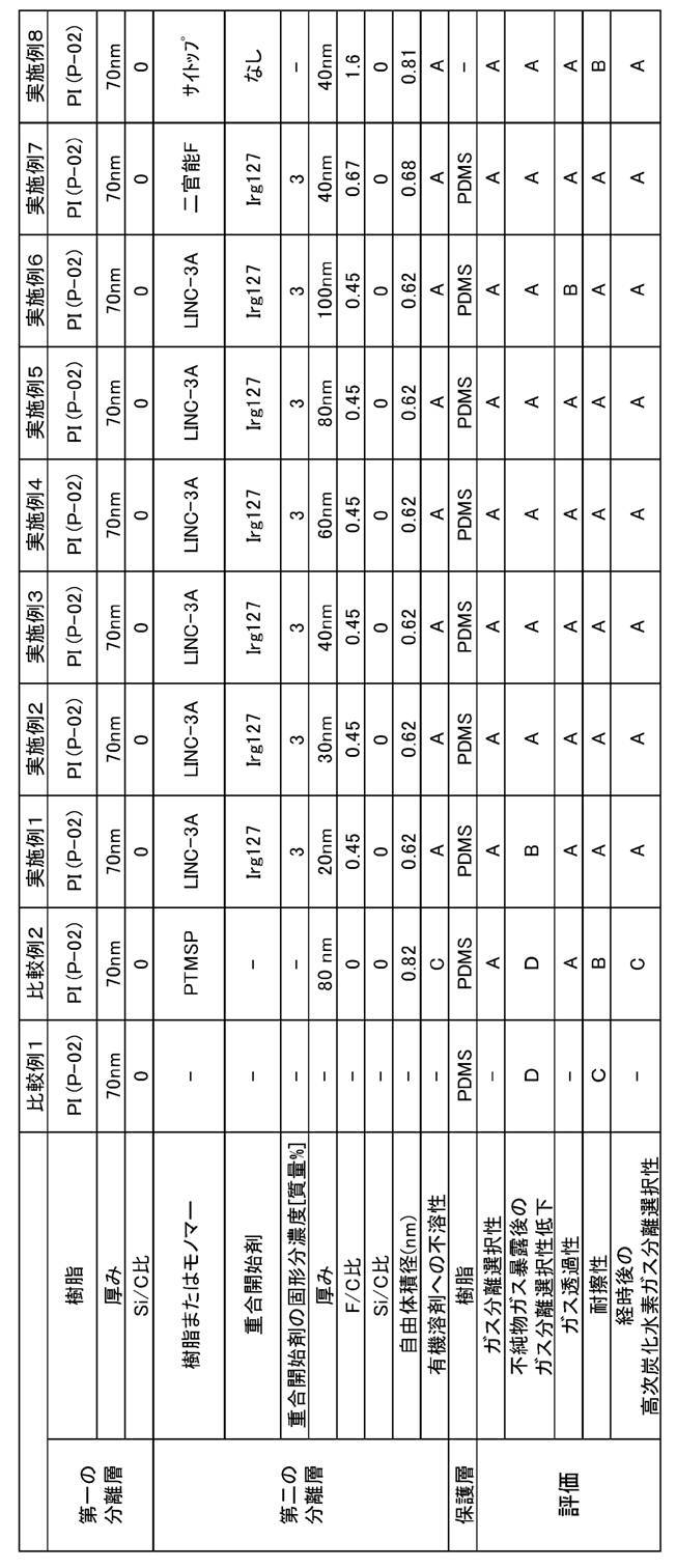
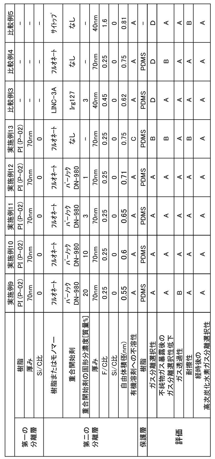
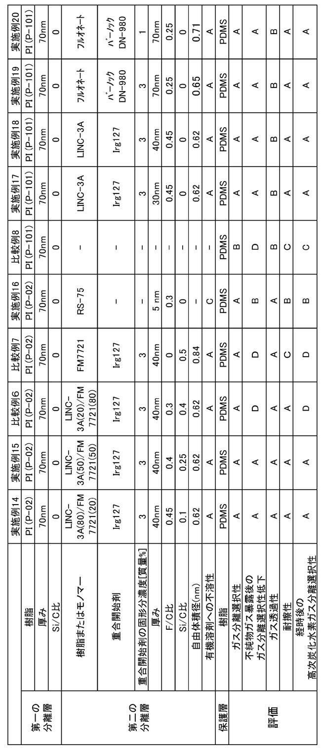
上記表3~5より、本発明のガス分離膜は、ガス分離選択性が高く、かつ、不純物ガス暴露後のガス分離選択性低下が抑制されたことがわかった。なお、第二の分離層としてLINC-3Aまたは二官能Fに由来するフルオロアクリレートの重合体を用いた場合は、特に第二の分離層の厚みが30~80nmであるとすべての評価がA評価であった。また、第二の分離層としてサイトップまたはフルオネートに由来するフルオロオレフィンの重合体(フルオロオレフィンとイソシアネートの共重合体)を用いた場合は、第二の分離層の形成用の組成物がフルオロオレフィンの重合体の前駆体に対して固形分濃度1~10質量%の重合開始剤(イソシアネートである硬化剤)を用いるとすべての評価がA評価であった。
一方、比較例1より、第二の分離層を設けない場合、不純物ガス暴露後のガス分離選択性が大きく低下することがわかった。
比較例2より、第二の分離層のF/C比の最大値が本発明で規定する下限値を下回る場合、不純物ガス暴露後のガス分離選択性が大きく低下することがわかった。
比較例3~5より、第一の分離層を設けない場合、ガス分離選択性(CO2/CH4ガス分離選択性)が低いことが分かった。ただし、比較例3~5のガス分離膜はある程度ガス分離選択性を有しており、比較例3~5で形成した第二の分離層は本明細書中で定義する「分離選択性を有する層」であった。
比較例6より、第二の分離層のSi/C比が本発明で規定する上限値を上回る場合、不純物ガス暴露後のガス分離選択性が大きく低下することがわかった。
比較例7より、第二の分離層のF/C比の最大値が本発明で規定する下限値を下回り、かつ、第二の分離層のSi/C比が本発明で規定する上限値を上回る場合、不純物ガス暴露後のガス分離選択性が大きく低下することがわかった。
一方、比較例1より、第二の分離層を設けない場合、不純物ガス暴露後のガス分離選択性が大きく低下することがわかった。
比較例2より、第二の分離層のF/C比の最大値が本発明で規定する下限値を下回る場合、不純物ガス暴露後のガス分離選択性が大きく低下することがわかった。
比較例3~5より、第一の分離層を設けない場合、ガス分離選択性(CO2/CH4ガス分離選択性)が低いことが分かった。ただし、比較例3~5のガス分離膜はある程度ガス分離選択性を有しており、比較例3~5で形成した第二の分離層は本明細書中で定義する「分離選択性を有する層」であった。
比較例6より、第二の分離層のSi/C比が本発明で規定する上限値を上回る場合、不純物ガス暴露後のガス分離選択性が大きく低下することがわかった。
比較例7より、第二の分離層のF/C比の最大値が本発明で規定する下限値を下回り、かつ、第二の分離層のSi/C比が本発明で規定する上限値を上回る場合、不純物ガス暴露後のガス分離選択性が大きく低下することがわかった。
なお、各実施例および比較例のガス分離膜は、ガス分離膜に用いた材料から、第二の分離層の樹脂がアクリル酸エステル結合、メタクリル酸エステル結合、ウレタン結合およびエーテル結合を含むことがわかる。
[実施例101~120]
<モジュール化>
実施例1~20で作製したガス分離膜を用いて、特開平5-168869号公報の<0012>~<0017>を参考に、スパイラル型モジュールを作製した。得られたガス分離膜モジュールを、実施例101~120のガス分離膜モジュールとした。
作製した各実施例のガス分離膜モジュールは、内蔵するガス分離膜の性能のとおり、良好なものであることを確認した。
作製した各実施例のガス分離膜モジュールは、リーフ(リーフとはスパイラル型モジュールにおいて透過側の空間が中心管に接続されている、封筒状に折り曲げられたガス分離膜の部分のことを言う)の片面の中心の10cm×10cm内よりランダムに1cm×1cmを10点採取し、実施例1の方法に従い、深さ方向の元素比を算出すると、10点中9点以上で内蔵する分離膜の通りのものであることを確認した。またスパイラル型モジュールは、内蔵するガス分離膜の性能のとおり、良好なものであることを確認した。
<モジュール化>
実施例1~20で作製したガス分離膜を用いて、特開平5-168869号公報の<0012>~<0017>を参考に、スパイラル型モジュールを作製した。得られたガス分離膜モジュールを、実施例101~120のガス分離膜モジュールとした。
作製した各実施例のガス分離膜モジュールは、内蔵するガス分離膜の性能のとおり、良好なものであることを確認した。
作製した各実施例のガス分離膜モジュールは、リーフ(リーフとはスパイラル型モジュールにおいて透過側の空間が中心管に接続されている、封筒状に折り曲げられたガス分離膜の部分のことを言う)の片面の中心の10cm×10cm内よりランダムに1cm×1cmを10点採取し、実施例1の方法に従い、深さ方向の元素比を算出すると、10点中9点以上で内蔵する分離膜の通りのものであることを確認した。またスパイラル型モジュールは、内蔵するガス分離膜の性能のとおり、良好なものであることを確認した。
3 第一の分離層
4 支持体
8 第二の分離層
9 保護層
10 ガス分離膜
21 アルミ板
22 カプトンテープ
4 支持体
8 第二の分離層
9 保護層
10 ガス分離膜
21 アルミ板
22 カプトンテープ
Claims (15)
- 第一の分離層と、第二の分離層とを含み、
前記第一の分離層は、前記第二の分離層側の前記第一の分離層の界面におけるケイ素原子の数の炭素原子の数に対する比であるSi/C比が0.3以下であり、
前記第二の分離層は、フッ素原子の数の炭素原子の数に対する比であるF/C比の最大値が0.20以上であり、かつ、F/C比が最大値をとる部分におけるSi/C比が0.3以下である、ガス分離膜。 - ガスが供給される側から、前記第二の分離層、前記第一の分離層の順に配置される、請求項1に記載のガス分離膜。
- 前記第二の分離層の厚みが20~200nmである、請求項1または2に記載のガス分離膜。
- 前記第二の分離層の自由体積径が0.6nm以上である、請求項1~3のいずれか一項に記載のガス分離膜。
- 前記第二の分離層は、組成比が質量比で1:1であるトルエンおよびヘプタンからなる有機溶剤に不溶である、請求項1~4のいずれか一項に記載のガス分離膜。
- 前記第二の分離層が樹脂を含み、
前記第二の分離層の樹脂としてフルオロ(メタ)アクリレートの重合体およびフルオロオレフィンの重合体のうち少なくとも1種類を含む、請求項1~5のいずれか一項に記載のガス分離膜。 - 前記第二の分離層が樹脂を含み、
前記第二の分離層の樹脂がアクリル酸エステル結合、メタクリル酸エステル結合、ウレタン結合およびエーテル結合のうち少なくとも1種類を含む、請求項1~6のいずれか一項に記載のガス分離膜。 - 前記第二の分離層はフッ素含有界面活性剤を含む、請求項1~7のいずれか一項に記載のガス分離膜。
- 前記第一の分離層が樹脂を含み、
前記第一の分離層の樹脂がセルロース類またはポリイミドである、請求項1~8のいずれか一項に記載のガス分離膜。 - 前記第一の分離層の樹脂が4,4’-(ヘキサフルオロイソプロピリデン)ジフタル酸無水物に由来する構造を含むポリイミドである、請求項9に記載のガス分離膜。
- 前記第一の分離層の樹脂がスルホンアミド基を含むポリイミドである、請求項9または10に記載のガス分離膜。
- 保護層をさらに有し、
前記保護層がシロキサン結合を有する化合物を含む、請求項1~11のいずれか一項に記載のガス分離膜。 - 前記保護層が前記第二の分離層と直接接し、
ガスが供給される側から、保護層、前記第二の分離層の順に配置される、請求項12に記載のガス分離膜。 - 請求項1~13のいずれか一項に記載のガス分離膜を有するガス分離膜モジュール。
- 請求項14に記載のガス分離膜モジュールを有するガス分離装置。
Priority Applications (1)
| Application Number | Priority Date | Filing Date | Title |
|---|---|---|---|
| US16/186,606 US10486101B2 (en) | 2016-07-25 | 2018-11-12 | Gas separation membrane, gas separation membrane module, and gas separation device |
Applications Claiming Priority (2)
| Application Number | Priority Date | Filing Date | Title |
|---|---|---|---|
| JP2016145267A JP2019162565A (ja) | 2016-07-25 | 2016-07-25 | ガス分離膜、ガス分離膜モジュールおよびガス分離装置 |
| JP2016-145267 | 2016-07-25 |
Related Child Applications (1)
| Application Number | Title | Priority Date | Filing Date |
|---|---|---|---|
| US16/186,606 Continuation US10486101B2 (en) | 2016-07-25 | 2018-11-12 | Gas separation membrane, gas separation membrane module, and gas separation device |
Publications (1)
| Publication Number | Publication Date |
|---|---|
| WO2018020949A1 true WO2018020949A1 (ja) | 2018-02-01 |
Family
ID=61015999
Family Applications (1)
| Application Number | Title | Priority Date | Filing Date |
|---|---|---|---|
| PCT/JP2017/023880 Ceased WO2018020949A1 (ja) | 2016-07-25 | 2017-06-29 | ガス分離膜、ガス分離膜モジュールおよびガス分離装置 |
Country Status (3)
| Country | Link |
|---|---|
| US (1) | US10486101B2 (ja) |
| JP (1) | JP2019162565A (ja) |
| WO (1) | WO2018020949A1 (ja) |
Cited By (2)
| Publication number | Priority date | Publication date | Assignee | Title |
|---|---|---|---|---|
| WO2020180353A1 (en) * | 2019-03-04 | 2020-09-10 | Saudi Arabian Oil Company | Crosslinked polyethylene glycol polymer membranes for gas separation |
| WO2020196669A1 (ja) * | 2019-03-27 | 2020-10-01 | デンカ株式会社 | 組成物 |
Families Citing this family (9)
| Publication number | Priority date | Publication date | Assignee | Title |
|---|---|---|---|---|
| JP6626980B2 (ja) * | 2016-08-31 | 2019-12-25 | 富士フイルム株式会社 | 新規m−フェニレンジアミン化合物、及びこれを用いた高分子化合物の製造方法 |
| JP7451142B2 (ja) * | 2019-10-31 | 2024-03-18 | 旭化成株式会社 | ガス分離膜 |
| KR102383657B1 (ko) * | 2020-07-15 | 2022-04-05 | 한국화학연구원 | 고투과성 거터층을 포함하는 복합막 및 이의 제조방법 |
| KR20230142731A (ko) | 2021-02-03 | 2023-10-11 | 도날드슨 컴파니, 인코포레이티드 | 퍼플루오로폴리에테르 병솔형 중합체를 포함하는 조성물및 물품, 그리고 이의 제조 및 사용 방법 |
| GB202104467D0 (en) * | 2021-03-30 | 2021-05-12 | Fujifilm Mfg Europe Bv | Gas separation membranes |
| JP2024042578A (ja) * | 2022-09-15 | 2024-03-28 | セイコーエプソン株式会社 | 気体分離膜および気体分離膜の製造方法 |
| JP2024060788A (ja) * | 2022-10-20 | 2024-05-07 | セイコーエプソン株式会社 | 気体分離膜および気体分離膜の製造方法 |
| JP2024060738A (ja) * | 2022-10-20 | 2024-05-07 | セイコーエプソン株式会社 | 気体分離膜 |
| KR102726486B1 (ko) * | 2022-12-30 | 2024-11-06 | 현대제철 주식회사 | 핫 스탬핑 부품 |
Citations (9)
| Publication number | Priority date | Publication date | Assignee | Title |
|---|---|---|---|---|
| JPH05329343A (ja) * | 1992-05-27 | 1993-12-14 | Asahi Chem Ind Co Ltd | フッ素系重合体よりなるガス分離膜 |
| JPH07251046A (ja) * | 1993-10-20 | 1995-10-03 | L'air Liquide | ガス分離膜のフルオロポリマーによる後処理 |
| JPH1085571A (ja) * | 1996-07-26 | 1998-04-07 | Dainippon Ink & Chem Inc | 分離膜 |
| JP2013031852A (ja) * | 2012-11-22 | 2013-02-14 | Asahi Kasei Chemicals Corp | プリーツ成形体 |
| JP2014014808A (ja) * | 2012-07-11 | 2014-01-30 | Fujifilm Corp | 二酸化炭素分離用複合体の製造方法、二酸化炭素分離用複合体、及び二酸化炭素分離用モジュール |
| JP2015073980A (ja) * | 2013-10-11 | 2015-04-20 | 富士フイルム株式会社 | ガス分離膜およびガス分離膜モジュール |
| JP2015160167A (ja) * | 2014-02-26 | 2015-09-07 | 富士フイルム株式会社 | ガス分離膜、ガス分離モジュール、ガス分離装置、及びガス分離方法 |
| JP2015160201A (ja) * | 2014-02-28 | 2015-09-07 | 富士フイルム株式会社 | ガス分離膜およびガス分離膜モジュール |
| WO2016047351A1 (ja) * | 2014-09-22 | 2016-03-31 | 富士フイルム株式会社 | ガス分離膜、ガス分離モジュール、ガス分離装置、及びガス分離方法 |
Family Cites Families (18)
| Publication number | Priority date | Publication date | Assignee | Title |
|---|---|---|---|---|
| JPS60118217A (ja) | 1983-11-29 | 1985-06-25 | Daikin Ind Ltd | 気体分離膜 |
| US5183534A (en) * | 1990-03-09 | 1993-02-02 | Amoco Corporation | Wet-etch process and composition |
| EP0634673B1 (en) * | 1993-07-13 | 1999-10-20 | Menicon Co., Ltd. | Ocular lens material |
| US5658669A (en) | 1994-05-09 | 1997-08-19 | Hoechst Aktiengesellschaft | Composite membranes and processes for their production |
| JPH0852332A (ja) | 1994-06-08 | 1996-02-27 | Nitto Denko Corp | 気体用複合分離膜及びその製造方法 |
| US5649045A (en) * | 1995-12-13 | 1997-07-15 | Amoco Corporation | Polymide optical waveguide structures |
| US6500603B1 (en) * | 1999-11-11 | 2002-12-31 | Mitsui Chemicals, Inc. | Method for manufacturing polymer optical waveguide |
| US6836608B2 (en) * | 2000-12-28 | 2004-12-28 | Matsushita Electric Industrial Co., Ltd. | Planar optical waveguide, method for manufacturing the same and polymer optical waveguide |
| US7324723B2 (en) * | 2003-10-06 | 2008-01-29 | Mitsui Chemicals, Inc. | Optical waveguide having specular surface formed by laser beam machining |
| TWI349013B (en) * | 2007-10-03 | 2011-09-21 | Univ Nat Taiwan | Polyimide-titania hybrid materials and method of preparing thin films |
| CN103630961A (zh) * | 2008-01-31 | 2014-03-12 | 日东电工株式会社 | 偏振片保护膜、偏振板及图像显示装置 |
| JP5747730B2 (ja) | 2010-08-11 | 2015-07-15 | 宇部興産株式会社 | ポリイミドガス分離膜、及びガス分離方法 |
| US20140138317A1 (en) | 2012-11-16 | 2014-05-22 | Uop Llc | Blend polymeric membranes containing fluorinated ethylene-propylene polymers for gas separations |
| CN104395375B (zh) * | 2013-06-26 | 2017-04-05 | 东丽株式会社 | 聚酰亚胺前体、聚酰亚胺、使用了它们的柔性基板、滤色器及其制造方法以及柔性显示器件 |
| US11299555B2 (en) * | 2016-03-03 | 2022-04-12 | Toagosei Co., Ltd | Method for diagnosing alzheimer's disease using signal peptide as indicator |
| KR102624985B1 (ko) * | 2016-07-26 | 2024-01-16 | 삼성전자주식회사 | 마스크 블랭크, 위상 시프트 마스크 및 그 제조방법 |
| JP2019166418A (ja) * | 2016-08-08 | 2019-10-03 | 富士フイルム株式会社 | ガス分離膜、ガス分離膜モジュールおよびガス分離装置 |
| JP6772951B2 (ja) * | 2017-05-09 | 2020-10-21 | トヨタ自動車株式会社 | 車両用動力伝達装置の制御装置 |
-
2016
- 2016-07-25 JP JP2016145267A patent/JP2019162565A/ja active Pending
-
2017
- 2017-06-29 WO PCT/JP2017/023880 patent/WO2018020949A1/ja not_active Ceased
-
2018
- 2018-11-12 US US16/186,606 patent/US10486101B2/en active Active
Patent Citations (9)
| Publication number | Priority date | Publication date | Assignee | Title |
|---|---|---|---|---|
| JPH05329343A (ja) * | 1992-05-27 | 1993-12-14 | Asahi Chem Ind Co Ltd | フッ素系重合体よりなるガス分離膜 |
| JPH07251046A (ja) * | 1993-10-20 | 1995-10-03 | L'air Liquide | ガス分離膜のフルオロポリマーによる後処理 |
| JPH1085571A (ja) * | 1996-07-26 | 1998-04-07 | Dainippon Ink & Chem Inc | 分離膜 |
| JP2014014808A (ja) * | 2012-07-11 | 2014-01-30 | Fujifilm Corp | 二酸化炭素分離用複合体の製造方法、二酸化炭素分離用複合体、及び二酸化炭素分離用モジュール |
| JP2013031852A (ja) * | 2012-11-22 | 2013-02-14 | Asahi Kasei Chemicals Corp | プリーツ成形体 |
| JP2015073980A (ja) * | 2013-10-11 | 2015-04-20 | 富士フイルム株式会社 | ガス分離膜およびガス分離膜モジュール |
| JP2015160167A (ja) * | 2014-02-26 | 2015-09-07 | 富士フイルム株式会社 | ガス分離膜、ガス分離モジュール、ガス分離装置、及びガス分離方法 |
| JP2015160201A (ja) * | 2014-02-28 | 2015-09-07 | 富士フイルム株式会社 | ガス分離膜およびガス分離膜モジュール |
| WO2016047351A1 (ja) * | 2014-09-22 | 2016-03-31 | 富士フイルム株式会社 | ガス分離膜、ガス分離モジュール、ガス分離装置、及びガス分離方法 |
Cited By (7)
| Publication number | Priority date | Publication date | Assignee | Title |
|---|---|---|---|---|
| WO2020180353A1 (en) * | 2019-03-04 | 2020-09-10 | Saudi Arabian Oil Company | Crosslinked polyethylene glycol polymer membranes for gas separation |
| US11135556B2 (en) | 2019-03-04 | 2021-10-05 | Saudi Arabian Oil Company | Crosslinked polyethylene glycol polymer membranes for gas separation |
| WO2020196669A1 (ja) * | 2019-03-27 | 2020-10-01 | デンカ株式会社 | 組成物 |
| CN113227159A (zh) * | 2019-03-27 | 2021-08-06 | 电化株式会社 | 组合物 |
| JP2023012530A (ja) * | 2019-03-27 | 2023-01-25 | デンカ株式会社 | 組成物 |
| CN113227159B (zh) * | 2019-03-27 | 2024-04-19 | 电化株式会社 | 组合物 |
| JP7514285B2 (ja) | 2019-03-27 | 2024-07-10 | デンカ株式会社 | 組成物 |
Also Published As
| Publication number | Publication date |
|---|---|
| JP2019162565A (ja) | 2019-09-26 |
| US10486101B2 (en) | 2019-11-26 |
| US20190076777A1 (en) | 2019-03-14 |
Similar Documents
| Publication | Publication Date | Title |
|---|---|---|
| WO2018020949A1 (ja) | ガス分離膜、ガス分離膜モジュールおよびガス分離装置 | |
| US10974207B2 (en) | Gas separation membrane, gas separation membrane module, and gas separation device | |
| Swaidan et al. | Physical aging, plasticization and their effects on gas permeation in “rigid” polymers of intrinsic microporosity | |
| US11071953B2 (en) | Gas separation membrane, method of producing gas separation membrane, gas separation membrane module, and gas separator | |
| US9975092B2 (en) | Gas separation membrane and gas separation membrane module | |
| TWI498354B (zh) | 聚合物、聚合物膜及其製造方法 | |
| Yampolskii et al. | Gas permeability and free volume of highly branched substituted acetylene polymers | |
| JP2015528739A (ja) | 相互混合層を有するガス分離膜 | |
| US20130247756A1 (en) | Uv-rearranged pim-1 polymeric membranes and a process of preparing thereof | |
| JP6652575B2 (ja) | 保護層付きガス分離膜、保護層付きガス分離膜の製造方法、ガス分離膜モジュール及びガス分離装置 | |
| US10035107B2 (en) | Composite membrane comprising layer of perfluoropolyether on hydrophilic substrate | |
| CN104781000A (zh) | 用于气体分离的氟化乙烯-丙烯聚合物膜 | |
| Huang et al. | Effect of branch length on the structural and separation properties of hyperbranched poly (1, 3-dioxolane) | |
| WO2015046141A1 (ja) | ガス分離膜およびガス分離膜の製造方法ならびにガス分離膜モジュール | |
| CN104822440A (zh) | 用于气体分离的含有氟化乙烯-丙烯聚合物的共混聚合物膜 | |
| WO2017038285A1 (ja) | ガス分離複合膜の製造方法、液組成物、ガス分離複合膜、ガス分離モジュール、ガス分離装置及びガス分離方法 | |
| US20180280892A1 (en) | Gas separation membrane, method of producing gas separation membrane, gas separation membrane module, and gas separator | |
| CN112566714A (zh) | 用于气体分离技术的氟化聚三唑膜材料 | |
| JP2018012089A (ja) | ガス分離膜、ガス分離膜の製造方法、ガス分離膜モジュールおよびガス分離装置 | |
| RU2390372C2 (ru) | Мембранное разделение газов | |
| JP2018027520A (ja) | ガス分離膜、ガス分離膜モジュールおよびガス分離装置 | |
| EP2051797B1 (fr) | Procede de separation par membrane d'hydrocarbures lineaires au sein d'un melange d'hydrocarbures | |
| JP2023530810A (ja) | 非晶質架橋フッ素コポリマーからなるガス分離物品ならびにその製造方法および使用方法 | |
| US20260084115A1 (en) | Gas Separation Membranes | |
| JP2022084357A (ja) | 酸化グラフェン層を有する複合半透膜 |
Legal Events
| Date | Code | Title | Description |
|---|---|---|---|
| 121 | Ep: the epo has been informed by wipo that ep was designated in this application |
Ref document number: 17833958 Country of ref document: EP Kind code of ref document: A1 |
|
| NENP | Non-entry into the national phase |
Ref country code: DE |
|
| 122 | Ep: pct application non-entry in european phase |
Ref document number: 17833958 Country of ref document: EP Kind code of ref document: A1 |
|
| NENP | Non-entry into the national phase |
Ref country code: JP |