WO2018012147A1 - 車両の制御方法および車両の制御装置 - Google Patents
車両の制御方法および車両の制御装置 Download PDFInfo
- Publication number
- WO2018012147A1 WO2018012147A1 PCT/JP2017/020984 JP2017020984W WO2018012147A1 WO 2018012147 A1 WO2018012147 A1 WO 2018012147A1 JP 2017020984 W JP2017020984 W JP 2017020984W WO 2018012147 A1 WO2018012147 A1 WO 2018012147A1
- Authority
- WO
- WIPO (PCT)
- Prior art keywords
- vehicle
- control
- driver
- host vehicle
- follow
- Prior art date
Links
Images


Classifications
-
- B—PERFORMING OPERATIONS; TRANSPORTING
- B60—VEHICLES IN GENERAL
- B60W—CONJOINT CONTROL OF VEHICLE SUB-UNITS OF DIFFERENT TYPE OR DIFFERENT FUNCTION; CONTROL SYSTEMS SPECIALLY ADAPTED FOR HYBRID VEHICLES; ROAD VEHICLE DRIVE CONTROL SYSTEMS FOR PURPOSES NOT RELATED TO THE CONTROL OF A PARTICULAR SUB-UNIT
- B60W30/00—Purposes of road vehicle drive control systems not related to the control of a particular sub-unit, e.g. of systems using conjoint control of vehicle sub-units, or advanced driver assistance systems for ensuring comfort, stability and safety or drive control systems for propelling or retarding the vehicle
- B60W30/14—Adaptive cruise control
- B60W30/16—Control of distance between vehicles, e.g. keeping a distance to preceding vehicle
- B60W30/17—Control of distance between vehicles, e.g. keeping a distance to preceding vehicle with provision for special action when the preceding vehicle comes to a halt, e.g. stop and go
-
- B—PERFORMING OPERATIONS; TRANSPORTING
- B60—VEHICLES IN GENERAL
- B60W—CONJOINT CONTROL OF VEHICLE SUB-UNITS OF DIFFERENT TYPE OR DIFFERENT FUNCTION; CONTROL SYSTEMS SPECIALLY ADAPTED FOR HYBRID VEHICLES; ROAD VEHICLE DRIVE CONTROL SYSTEMS FOR PURPOSES NOT RELATED TO THE CONTROL OF A PARTICULAR SUB-UNIT
- B60W30/00—Purposes of road vehicle drive control systems not related to the control of a particular sub-unit, e.g. of systems using conjoint control of vehicle sub-units, or advanced driver assistance systems for ensuring comfort, stability and safety or drive control systems for propelling or retarding the vehicle
- B60W30/14—Adaptive cruise control
- B60W30/16—Control of distance between vehicles, e.g. keeping a distance to preceding vehicle
-
- B—PERFORMING OPERATIONS; TRANSPORTING
- B60—VEHICLES IN GENERAL
- B60K—ARRANGEMENT OR MOUNTING OF PROPULSION UNITS OR OF TRANSMISSIONS IN VEHICLES; ARRANGEMENT OR MOUNTING OF PLURAL DIVERSE PRIME-MOVERS IN VEHICLES; AUXILIARY DRIVES FOR VEHICLES; INSTRUMENTATION OR DASHBOARDS FOR VEHICLES; ARRANGEMENTS IN CONNECTION WITH COOLING, AIR INTAKE, GAS EXHAUST OR FUEL SUPPLY OF PROPULSION UNITS IN VEHICLES
- B60K31/00—Vehicle fittings, acting on a single sub-unit only, for automatically controlling vehicle speed, i.e. preventing speed from exceeding an arbitrarily established velocity or maintaining speed at a particular velocity, as selected by the vehicle operator
-
- B—PERFORMING OPERATIONS; TRANSPORTING
- B60—VEHICLES IN GENERAL
- B60R—VEHICLES, VEHICLE FITTINGS, OR VEHICLE PARTS, NOT OTHERWISE PROVIDED FOR
- B60R21/00—Arrangements or fittings on vehicles for protecting or preventing injuries to occupants or pedestrians in case of accidents or other traffic risks
-
- B—PERFORMING OPERATIONS; TRANSPORTING
- B60—VEHICLES IN GENERAL
- B60W—CONJOINT CONTROL OF VEHICLE SUB-UNITS OF DIFFERENT TYPE OR DIFFERENT FUNCTION; CONTROL SYSTEMS SPECIALLY ADAPTED FOR HYBRID VEHICLES; ROAD VEHICLE DRIVE CONTROL SYSTEMS FOR PURPOSES NOT RELATED TO THE CONTROL OF A PARTICULAR SUB-UNIT
- B60W10/00—Conjoint control of vehicle sub-units of different type or different function
- B60W10/04—Conjoint control of vehicle sub-units of different type or different function including control of propulsion units
- B60W10/06—Conjoint control of vehicle sub-units of different type or different function including control of propulsion units including control of combustion engines
-
- B—PERFORMING OPERATIONS; TRANSPORTING
- B60—VEHICLES IN GENERAL
- B60W—CONJOINT CONTROL OF VEHICLE SUB-UNITS OF DIFFERENT TYPE OR DIFFERENT FUNCTION; CONTROL SYSTEMS SPECIALLY ADAPTED FOR HYBRID VEHICLES; ROAD VEHICLE DRIVE CONTROL SYSTEMS FOR PURPOSES NOT RELATED TO THE CONTROL OF A PARTICULAR SUB-UNIT
- B60W10/00—Conjoint control of vehicle sub-units of different type or different function
- B60W10/18—Conjoint control of vehicle sub-units of different type or different function including control of braking systems
-
- B—PERFORMING OPERATIONS; TRANSPORTING
- B60—VEHICLES IN GENERAL
- B60W—CONJOINT CONTROL OF VEHICLE SUB-UNITS OF DIFFERENT TYPE OR DIFFERENT FUNCTION; CONTROL SYSTEMS SPECIALLY ADAPTED FOR HYBRID VEHICLES; ROAD VEHICLE DRIVE CONTROL SYSTEMS FOR PURPOSES NOT RELATED TO THE CONTROL OF A PARTICULAR SUB-UNIT
- B60W30/00—Purposes of road vehicle drive control systems not related to the control of a particular sub-unit, e.g. of systems using conjoint control of vehicle sub-units, or advanced driver assistance systems for ensuring comfort, stability and safety or drive control systems for propelling or retarding the vehicle
- B60W30/14—Adaptive cruise control
-
- B—PERFORMING OPERATIONS; TRANSPORTING
- B60—VEHICLES IN GENERAL
- B60W—CONJOINT CONTROL OF VEHICLE SUB-UNITS OF DIFFERENT TYPE OR DIFFERENT FUNCTION; CONTROL SYSTEMS SPECIALLY ADAPTED FOR HYBRID VEHICLES; ROAD VEHICLE DRIVE CONTROL SYSTEMS FOR PURPOSES NOT RELATED TO THE CONTROL OF A PARTICULAR SUB-UNIT
- B60W30/00—Purposes of road vehicle drive control systems not related to the control of a particular sub-unit, e.g. of systems using conjoint control of vehicle sub-units, or advanced driver assistance systems for ensuring comfort, stability and safety or drive control systems for propelling or retarding the vehicle
- B60W30/18—Propelling the vehicle
- B60W30/18009—Propelling the vehicle related to particular drive situations
- B60W30/18027—Drive off, accelerating from standstill
-
- B—PERFORMING OPERATIONS; TRANSPORTING
- B60—VEHICLES IN GENERAL
- B60W—CONJOINT CONTROL OF VEHICLE SUB-UNITS OF DIFFERENT TYPE OR DIFFERENT FUNCTION; CONTROL SYSTEMS SPECIALLY ADAPTED FOR HYBRID VEHICLES; ROAD VEHICLE DRIVE CONTROL SYSTEMS FOR PURPOSES NOT RELATED TO THE CONTROL OF A PARTICULAR SUB-UNIT
- B60W30/00—Purposes of road vehicle drive control systems not related to the control of a particular sub-unit, e.g. of systems using conjoint control of vehicle sub-units, or advanced driver assistance systems for ensuring comfort, stability and safety or drive control systems for propelling or retarding the vehicle
- B60W30/18—Propelling the vehicle
- B60W30/18009—Propelling the vehicle related to particular drive situations
- B60W30/181—Preparing for stopping
-
- B—PERFORMING OPERATIONS; TRANSPORTING
- B60—VEHICLES IN GENERAL
- B60W—CONJOINT CONTROL OF VEHICLE SUB-UNITS OF DIFFERENT TYPE OR DIFFERENT FUNCTION; CONTROL SYSTEMS SPECIALLY ADAPTED FOR HYBRID VEHICLES; ROAD VEHICLE DRIVE CONTROL SYSTEMS FOR PURPOSES NOT RELATED TO THE CONTROL OF A PARTICULAR SUB-UNIT
- B60W40/00—Estimation or calculation of non-directly measurable driving parameters for road vehicle drive control systems not related to the control of a particular sub unit, e.g. by using mathematical models
- B60W40/10—Estimation or calculation of non-directly measurable driving parameters for road vehicle drive control systems not related to the control of a particular sub unit, e.g. by using mathematical models related to vehicle motion
- B60W40/105—Speed
-
- B—PERFORMING OPERATIONS; TRANSPORTING
- B60—VEHICLES IN GENERAL
- B60W—CONJOINT CONTROL OF VEHICLE SUB-UNITS OF DIFFERENT TYPE OR DIFFERENT FUNCTION; CONTROL SYSTEMS SPECIALLY ADAPTED FOR HYBRID VEHICLES; ROAD VEHICLE DRIVE CONTROL SYSTEMS FOR PURPOSES NOT RELATED TO THE CONTROL OF A PARTICULAR SUB-UNIT
- B60W50/00—Details of control systems for road vehicle drive control not related to the control of a particular sub-unit, e.g. process diagnostic or vehicle driver interfaces
- B60W50/08—Interaction between the driver and the control system
- B60W50/10—Interpretation of driver requests or demands
-
- B—PERFORMING OPERATIONS; TRANSPORTING
- B60—VEHICLES IN GENERAL
- B60W—CONJOINT CONTROL OF VEHICLE SUB-UNITS OF DIFFERENT TYPE OR DIFFERENT FUNCTION; CONTROL SYSTEMS SPECIALLY ADAPTED FOR HYBRID VEHICLES; ROAD VEHICLE DRIVE CONTROL SYSTEMS FOR PURPOSES NOT RELATED TO THE CONTROL OF A PARTICULAR SUB-UNIT
- B60W50/00—Details of control systems for road vehicle drive control not related to the control of a particular sub-unit, e.g. process diagnostic or vehicle driver interfaces
- B60W50/08—Interaction between the driver and the control system
- B60W50/14—Means for informing the driver, warning the driver or prompting a driver intervention
-
- G—PHYSICS
- G08—SIGNALLING
- G08G—TRAFFIC CONTROL SYSTEMS
- G08G1/00—Traffic control systems for road vehicles
- G08G1/16—Anti-collision systems
-
- B—PERFORMING OPERATIONS; TRANSPORTING
- B60—VEHICLES IN GENERAL
- B60W—CONJOINT CONTROL OF VEHICLE SUB-UNITS OF DIFFERENT TYPE OR DIFFERENT FUNCTION; CONTROL SYSTEMS SPECIALLY ADAPTED FOR HYBRID VEHICLES; ROAD VEHICLE DRIVE CONTROL SYSTEMS FOR PURPOSES NOT RELATED TO THE CONTROL OF A PARTICULAR SUB-UNIT
- B60W50/00—Details of control systems for road vehicle drive control not related to the control of a particular sub-unit, e.g. process diagnostic or vehicle driver interfaces
- B60W50/08—Interaction between the driver and the control system
- B60W50/14—Means for informing the driver, warning the driver or prompting a driver intervention
- B60W2050/146—Display means
-
- B—PERFORMING OPERATIONS; TRANSPORTING
- B60—VEHICLES IN GENERAL
- B60W—CONJOINT CONTROL OF VEHICLE SUB-UNITS OF DIFFERENT TYPE OR DIFFERENT FUNCTION; CONTROL SYSTEMS SPECIALLY ADAPTED FOR HYBRID VEHICLES; ROAD VEHICLE DRIVE CONTROL SYSTEMS FOR PURPOSES NOT RELATED TO THE CONTROL OF A PARTICULAR SUB-UNIT
- B60W2520/00—Input parameters relating to overall vehicle dynamics
- B60W2520/04—Vehicle stop
-
- B—PERFORMING OPERATIONS; TRANSPORTING
- B60—VEHICLES IN GENERAL
- B60W—CONJOINT CONTROL OF VEHICLE SUB-UNITS OF DIFFERENT TYPE OR DIFFERENT FUNCTION; CONTROL SYSTEMS SPECIALLY ADAPTED FOR HYBRID VEHICLES; ROAD VEHICLE DRIVE CONTROL SYSTEMS FOR PURPOSES NOT RELATED TO THE CONTROL OF A PARTICULAR SUB-UNIT
- B60W2520/00—Input parameters relating to overall vehicle dynamics
- B60W2520/10—Longitudinal speed
-
- B—PERFORMING OPERATIONS; TRANSPORTING
- B60—VEHICLES IN GENERAL
- B60W—CONJOINT CONTROL OF VEHICLE SUB-UNITS OF DIFFERENT TYPE OR DIFFERENT FUNCTION; CONTROL SYSTEMS SPECIALLY ADAPTED FOR HYBRID VEHICLES; ROAD VEHICLE DRIVE CONTROL SYSTEMS FOR PURPOSES NOT RELATED TO THE CONTROL OF A PARTICULAR SUB-UNIT
- B60W2540/00—Input parameters relating to occupants
- B60W2540/12—Brake pedal position
-
- B—PERFORMING OPERATIONS; TRANSPORTING
- B60—VEHICLES IN GENERAL
- B60W—CONJOINT CONTROL OF VEHICLE SUB-UNITS OF DIFFERENT TYPE OR DIFFERENT FUNCTION; CONTROL SYSTEMS SPECIALLY ADAPTED FOR HYBRID VEHICLES; ROAD VEHICLE DRIVE CONTROL SYSTEMS FOR PURPOSES NOT RELATED TO THE CONTROL OF A PARTICULAR SUB-UNIT
- B60W2540/00—Input parameters relating to occupants
- B60W2540/18—Steering angle
-
- B—PERFORMING OPERATIONS; TRANSPORTING
- B60—VEHICLES IN GENERAL
- B60W—CONJOINT CONTROL OF VEHICLE SUB-UNITS OF DIFFERENT TYPE OR DIFFERENT FUNCTION; CONTROL SYSTEMS SPECIALLY ADAPTED FOR HYBRID VEHICLES; ROAD VEHICLE DRIVE CONTROL SYSTEMS FOR PURPOSES NOT RELATED TO THE CONTROL OF A PARTICULAR SUB-UNIT
- B60W2554/00—Input parameters relating to objects
- B60W2554/80—Spatial relation or speed relative to objects
- B60W2554/801—Lateral distance
-
- B—PERFORMING OPERATIONS; TRANSPORTING
- B60—VEHICLES IN GENERAL
- B60W—CONJOINT CONTROL OF VEHICLE SUB-UNITS OF DIFFERENT TYPE OR DIFFERENT FUNCTION; CONTROL SYSTEMS SPECIALLY ADAPTED FOR HYBRID VEHICLES; ROAD VEHICLE DRIVE CONTROL SYSTEMS FOR PURPOSES NOT RELATED TO THE CONTROL OF A PARTICULAR SUB-UNIT
- B60W2554/00—Input parameters relating to objects
- B60W2554/80—Spatial relation or speed relative to objects
- B60W2554/804—Relative longitudinal speed
Definitions
- the present invention relates to a vehicle control method and a vehicle control device that control the traveling of the host vehicle and the presentation of information.
- a problem to be solved by the present invention is a vehicle control method and vehicle control capable of starting the host vehicle at an appropriate timing during automatic traveling control for stopping the host vehicle without depending on a driver's brake operation. Is to provide a device.
- the present invention solves the above problem by presenting start instruction information when a stop of a preceding vehicle is detected during execution of automatic traveling control for stopping the host vehicle without depending on a driver's brake operation.
- the driver when the stop of the preceding vehicle is detected during the execution of the automatic traveling control for stopping the host vehicle without depending on the driver's brake operation, the driver indicates that the preceding vehicle has stopped. Since it is possible to instruct the start of the host vehicle at a desired timing after the start, it is possible to start the host vehicle at an appropriate timing even during the automatic driving control, as in the case where the driver manually operates. Become.
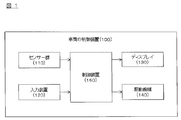
- FIG. 1 is a block diagram showing a vehicle control apparatus 100 according to the present embodiment.
- the vehicle control device 100 includes a sensor group 110, an input device 120, a display 130, a drive mechanism 140, and a control device 150. These devices are connected by a CAN (Controller Area Network) or other vehicle-mounted LAN in order to exchange information with each other.
- CAN Controller Area Network
- the sensor group 110 includes a GPS device that detects the position of the host vehicle, a vehicle speed sensor that detects the vehicle speed of the host vehicle, a steering angle sensor that detects the steering angle of the host vehicle, and obstacles and the host vehicle around the host vehicle travel. It consists of a ranging sensor that detects lanes, a camera that captures the surroundings of the vehicle, and the like. As the distance measuring sensor, a laser radar, an ultrasonic sensor, a sound wave sensor, an infrared sensor, or the like can be used.
- the input device 120 is a device that can be operated by the driver, and includes, for example, various switches for the driver to perform operations related to automatic travel control. The details of various switches relating to the automatic travel control included in the input device 120 will be described later.
- the display 130 presents various display information indicating the traveling state of the host vehicle on a screen included in the display 130.
- a display included in a navigation device a head-up display projected on a windshield, a display incorporated in an instrument panel, or the like can be used.
- the drive mechanism 140 includes an engine, a brake, a steering actuator, and the like for running the host vehicle. In the automatic travel control described later, the operation of the drive mechanism 140 is controlled by the control device 150.
- the control device 150 includes a ROM (Read Only Memory) that stores a program for controlling the traveling of the host vehicle, a CPU (Central Processing Unit) that executes the program stored in the ROM, and an accessible storage device. It consists of a functioning RAM (Random Access Memory).
- ROM Read Only Memory
- CPU Central Processing Unit
- RAM Random Access Memory
- As an operation circuit instead of or in addition to a CPU (Central Processing Unit), an MPU (Micro Processing Unit), a DSP (Digital Signal Processor), an ASIC (Application Specific Integrated Circuit), an FPGA (Field Programmable Gate Array), etc. Can be used.
- the control device 150 executes a program stored in the ROM by the CPU, thereby realizing a traveling state detection function for detecting the traveling state of the host vehicle and a traveling control function for controlling the traveling of the host vehicle. Below, each function with which the control apparatus 150 is provided is demonstrated.
- the control device 150 detects the traveling state of the host vehicle by the traveling state detection function. For example, the control device 150 detects the position, traveling speed, and steering angle of the host vehicle as the traveling state of the host vehicle from the GPS device, the vehicle speed sensor, and the steering angle sensor included in the sensor group 110 by the driving state detection function. can do. In addition, the control device 150 can also detect the lane mark of the own lane in which the host vehicle is traveling from the distance measuring sensor or the camera included in the sensor group 110 as the driving state of the host vehicle by the driving state detection function. Further, the control device 150 can detect the presence / absence of a preceding vehicle traveling ahead of the host vehicle as a driving state of the host vehicle from the distance measuring sensors and cameras included in the sensor group 110 by the driving state detection function.
- control device 150 detects the distance from the vehicle to the preceding vehicle, the traveling speed of the preceding vehicle, and the like from the distance measuring sensor and camera included in the sensor group 110 when the preceding vehicle exists. Can also be detected as the running state of the host vehicle.
- the control device 150 executes automatic traveling control for automatically controlling traveling of the host vehicle by the traveling control function.
- the control device 150 causes the driving control function to operate the driving mechanism 140 such as a steering actuator so that the host vehicle travels in the host lane based on the lane mark of the host lane detected by the driving state detection function. Control.
- the control apparatus 150 can perform lane keep control which controls the driving
- the control apparatus 150 judges whether a preceding vehicle exists based on the detection result of a driving state detection function by a driving control function.
- the control device 150 controls the operation of the drive mechanism 140 such as the engine and the brake by the travel control function, thereby driving the host vehicle at a predetermined set vehicle speed set by the driver.
- the operation of the drive mechanism 140 such as the engine and the brake is controlled to follow the preceding vehicle with the set vehicle speed set by the driver as an upper limit.
- follow-up running control for controlling the running of the host vehicle can be performed.
- lane keeping control, follow-up traveling control, and constant speed traveling control are collectively referred to as automatic traveling control.
- FIG. 2 is a diagram illustrating an example of the input device 120 related to automatic travel control (lane keep control, follow-up travel control, and constant speed travel control).
- the input device 120 includes an automatic travel control switch 121 for instructing on / off of automatic travel control, an inter-vehicle distance setting switch 122 for setting a set inter-vehicle distance in the follow-up travel control, and follow-up travel.
- a speed setting switch 123 for setting the set vehicle speed in the control and constant speed traveling control, and a start instruction switch 124 for instructing the start of the own vehicle when the own vehicle stops during the follow-up traveling control. .
- the control device 150 when the driver sets the automatic travel control switch 121 of the input device 120 to ON, the control device 150 automatically performs lane keeping control, follow-up travel control, and constant speed travel control by the travel control function. Start running control.
- the control device 150 can set the set inter-vehicle distance (for example, three stages of short, medium, and long) in the follow-up travel control by the driver operating the inter-vehicle distance setting switch 122 of the input device 120.
- Follow-up running control is executed by the running control function so as to follow the preceding vehicle at the set inter-vehicle distance set by the driver.
- control device 150 can set the set vehicle speed in the follow-up traveling control and the constant speed traveling control by the driver operating the speed setting switch 123 of the input device 120.
- control device 150 can perform follow-up running control that causes the host vehicle to follow the preceding vehicle with the set vehicle speed set by the driver as the upper limit by the running control function, and can automatically perform at the set vehicle speed set by the driver.
- Constant speed traveling control can be executed so that the vehicle travels.
- the control device 150 performs a process of stopping the host vehicle accompanying the preceding vehicle when the preceding vehicle stops in the case where the following control is performed by the traveling control function. . Then, the control device 150 determines whether or not the host vehicle has stopped by the traveling control function, and further determines whether or not the host vehicle is ready to start. When the vehicle is ready to start, the following traveling control is canceled, and instead, the following standby control is performed to stop the own vehicle until the driver gives a starting instruction.
- the following describes a method for determining whether or not the host vehicle has stopped, a method for determining whether or not the host vehicle is ready to start, and follow-up standby control for stopping the host vehicle until a driver gives a start instruction. To do.
- the control device 150 takes into account a detection error of the vehicle speed sensor by the travel control function, and performs a predetermined first time (for example, several seconds) after the travel speed of the host vehicle detected by the vehicle speed sensor becomes zero. ), It is determined that the host vehicle has stopped.
- the method for determining whether or not the host vehicle has stopped is not limited to the above configuration. For example, when the traveling speed of the host vehicle detected by the vehicle speed sensor becomes zero, it is determined that the host vehicle has stopped. It can also be set as the structure to do. Further, the follow-up running control is continuously performed until the first time elapses after the vehicle speed of the host vehicle becomes zero. For this reason, when the preceding vehicle restarts before the first time has elapsed since the vehicle speed of the host vehicle has become zero, the host vehicle will also automatically restart following this.
- the control device 150 determines that the host vehicle is ready to start when the host vehicle satisfies all of the predetermined startable conditions after the host vehicle stops by the travel control function. Specifically, in the present embodiment, the control device 150 uses the traveling control function to (1) the driver not stepping on the brake pedal, (2) the steering angle of the steering is not greater than a predetermined value, (3 ) The vehicle starts when all three startable conditions are met, that is, the notification message notifying that the automatic traveling control (lane keeping control, follow-up traveling control, and constant speed traveling control) cannot be executed is not displayed. Judge that it is possible.
- the notification message for notifying that automatic traveling control cannot be executed is, for example, that the driver may unintentionally step on the brake pedal when the vehicle is stopped during follow-up traveling control.
- the control device 150 can determine whether or not the host vehicle satisfies the startable condition based on the driving state of the host vehicle detected by the driving state detection function and the like.
- the control device 150 cancels the following traveling control that follows the preceding vehicle, and the driver Follow-up standby control is started to stop the traveling of the host vehicle until a start instruction is issued. Specifically, the control device 150 displays start instruction information for instructing the driver to start the host vehicle on the screen of the display 130 as follow-up standby control by the traveling control function.
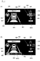
- FIG. 3 is a diagram showing an example of a screen displayed on the screen of the display 130.
- the control device 150 when the control device 150 is executing automatic travel control (control of one of lane keeping control, follow-up travel control, and constant speed travel control) by the travel control function, it is shown in FIG. In this way, the image IM1 indicating the host vehicle and the image IM2 indicating that the automatic travel control is being executed can be displayed on the display 130.
- the driving control function detects the lane mark of the own lane
- the control device 150 displays the image IM3 indicating the lane mark of the own lane, and when the preceding vehicle is detected, the preceding vehicle Can be displayed on the display 130.
- the image IM5 indicating that the steering control is being performed as shown in FIG. Can be displayed on the display 130.
- the control device 150 can also display an image IM6 indicating the set vehicle speed set by the driver and an image IM7 indicating the set inter-vehicle distance set by the driver on the display 130 by the traveling control function.
- the control device 150 displays a frame line IM8 that surrounds the preceding vehicle that is the target of the following traveling control on the display 130 when performing the following traveling control that causes the host vehicle to follow the preceding vehicle by the traveling control function. Can also be displayed.
- the control device 150 causes the display 130 to display an image IM9 indicating the shift position of the host vehicle and an image IM10 indicating the driving mode of the host vehicle by the driving control function. You can also.
- the control device 150 is configured to stop when the host vehicle is stopped due to the preceding vehicle being stopped, and when the host vehicle is in a state where the host vehicle can start.
- the start instruction information MSG for instructing the driver to start the host vehicle can be displayed on the display 130.
- the control device 150 causes the display 130 to display start instruction information such as “Res + when the start instruction switch 124 is pressed.” be able to.
- the driver sets the start instruction switch 124 shown in FIG. 2 to ON to indicate that the start instruction switch 124 is turned on from the start instruction switch 124 to the control device 150.
- a signal is output.
- control device 150 when the control device 150 receives an ON signal of the start instruction switch 124, the control device 150 switches from the follow-up standby control to the follow-up travel control by the travel control function, and controls the operation of the drive mechanism 140 such as the engine and the brake. Then, the host vehicle is started. As a result, the control device 150 according to the present embodiment stops the host vehicle accompanying the preceding vehicle in the follow-up traveling control, and when the host vehicle is ready to start, a timing desired by the driver. You can start your vehicle.
- the control device 150 switches from the follow-up standby control to the follow-up travel control by the travel control function.
- the follow-up running control is switched to the follow-up standby control, and the start instruction information is displayed on the screen of the display 130. In this way, even if the driver sets the start instruction switch 124 to be instructed to start the host vehicle, if the preceding vehicle is stopped and the host vehicle cannot start, after the second time has elapsed, Again, the start instruction information is presented to the driver.
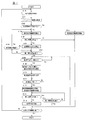
- FIG. 4 is a flowchart showing a travel control process in the control device 150 according to the present embodiment.
- the traveling control process described below is started when the automatic traveling control switch 121 is turned on by the driver.
- the traveling state of the host vehicle is detected by the traveling state detection function of the control device 150.
- the control device 150 detects the position information of the host vehicle from the GPS device included in the sensor group 110, the vehicle speed information of the host vehicle from the vehicle speed sensor, and the steering angle of the host vehicle from the steering angle sensor by the running state detection function. It is possible to detect the lane information of the own lane in which the host vehicle is traveling from the camera, and the presence / absence of the preceding vehicle and the position and speed information of the preceding vehicle from the ranging sensor and the camera as the traveling state of the host vehicle. Note that the control device 150 travel state detection function periodically detects various information indicating the travel state of the host vehicle even after step S101.
- step S102 the lane keeping control is started by the traveling control function of the control device 150.
- the control device 150 controls the operation of the driving mechanism 140 such as a steering actuator based on the lane mark of the own lane detected in step S101 by the traveling control function, thereby determining the traveling position in the width direction of the own vehicle. Lane keeping control can be performed.
- step S103 the traveling control function of the control device 150 determines whether there is a preceding vehicle based on the detection result of the preceding vehicle detected in step S101. If there is a preceding vehicle, the process proceeds to step S104, and follow-up running control for causing the host vehicle to follow the preceding vehicle at the set inter-vehicle distance set by the driver is started by the running control function. On the other hand, when the preceding vehicle does not exist, the process proceeds to step S117, and constant speed traveling control for causing the host vehicle to travel at the set vehicle speed set by the driver is started by the traveling control function.
- step S105 it is determined whether or not the preceding vehicle is stopped by the travel control function.
- step S106 since it is determined that the preceding vehicle has stopped during the follow-up traveling control, processing for stopping the traveling of the host vehicle is performed by the traveling control function.
- the control device 150 can stop the traveling of the host vehicle by controlling the operation of the driving mechanism 140 such as an engine or a brake by the traveling control function.
- step S107 the traveling control function determines whether or not a predetermined first time (for example, several seconds) has elapsed since the vehicle speed became zero.
- a predetermined first time for example, several seconds
- the host vehicle Is determined to have stopped. Therefore, until the first time has elapsed since the vehicle speed became zero, it is determined that the host vehicle has not stopped and the vehicle waits in step S107, and the first time has elapsed since the vehicle speed became zero.
- step S108 it is determined that the host vehicle has stopped.
- step S108 the traveling control function determines whether or not the host vehicle is ready to start.
- the driver does not step on the brake pedal
- the steering angle of the steering is not greater than a predetermined value
- automatic travel control (lane A state in which the host vehicle can start when all three startable conditions are met, that is, a notification message notifying the driver that keep control, follow-up travel control, and constant speed travel control) cannot be executed. Can be determined. If the host vehicle is not ready to start, the process waits in step S108 until the host vehicle is ready to start. If the host vehicle is ready to start, the process proceeds to step S109.
- step S109 the tracking control is canceled by the driving control function, and the tracking standby control is started.
- the follow-up running control is canceled and the follow-up standby control is started, the follow-up to the preceding vehicle is prohibited, and even if the preceding vehicle starts, the host vehicle remains stopped until an instruction from the driver is given.
- the control device 150 executes the processes of steps S110 to S111 as follow-up standby control by the travel control function.
- step S110 the start instruction information is displayed by the traveling control function.
- the control device 150 uses the traveling control function to display start instruction information such as “res + (start instruction switch 124) is restarted” on the screen of the display 130. Can be displayed.
- step S111 the travel control function determines whether the driver has issued a start instruction for the host vehicle in accordance with the start instruction information displayed in step S110. For example, when the driver sets the start instruction switch 124 to ON, the traveling control function can determine that the driver has issued a start instruction for the host vehicle. If the driver has not instructed to start the host vehicle, the process waits in step S111 until the driver instructs to start the host vehicle. If the driver has instructed to start the host vehicle, the process proceeds to step S112.
- step S112 the follow-up standby control is canceled and the follow-up running control is started by the running control function.
- the traveling control function determines whether the preceding vehicle is stopped. If the preceding vehicle is stopped even after the driver gives a start instruction for the host vehicle and starts the follow-up running control, the process proceeds to step S115.
- step S115 the travel control function determines whether a predetermined second time has elapsed since the driver instructed the vehicle to start. The second time may be the same time as the first time or may be a time different from the first time.
- step S115 No
- the instruction information is displayed on the display 130 (step S110).
- step S113 If it is determined in step S113 that the preceding vehicle has started before the second time has elapsed after the driver has issued a start instruction for the host vehicle, the process proceeds to step S114, where the traveling control function The vehicle is started.
- step S116 it is determined by the travel control function whether or not the automatic travel control is terminated.
- the control device 150 can determine that the automatic travel control is terminated when the driver sets the automatic travel control switch 121 to OFF by the travel control function. If the automatic travel control is not finished, the process returns to step S101, and the travel control process of FIG. 4 is continuously executed. And when automatic travel control is complete
- FIG. 5 is a diagram for explaining the travel control process according to the present embodiment.
- step S107 Yes
- the control apparatus 150 performs the process which displays start instruction information on the screen of the display 130, as shown in FIG.2 (B) at the time t3 (step S110).
- step S112 In the example shown in FIG. 5, at time t4 while starting instruction information is displayed on the screen of the display 130 from time t3, the driver presses the starting instruction switch 124 to instruct the start of the host vehicle ( Accordingly, the follow-up standby control is canceled at time t4, and the follow-up running control is resumed (step S112).
- step S115 Yes
- step S111 Yes
- step S115 A determination of whether or not is made.
- the control device 15 thereby performs the following traveling control.
- the vehicle is started (step S113).
- the host vehicle can be started immediately after the preceding vehicle starts.
- the driver when the stop of the preceding vehicle is detected during the automatic travel control that stops the host vehicle without depending on the driver's brake operation, the driver is instructed to start the host vehicle.
- the start instruction information is presented. More specifically, it is determined whether or not the own vehicle has stopped during the automatic travel control for stopping the own vehicle without depending on the driver's brake operation, and at the timing when the own vehicle is determined to have stopped.
- the start instruction information for instructing the driver to start is displayed.
- the driver can set a desired timing after the host vehicle stops (for example, before the preceding vehicle starts, or a signal that allows the traffic signal to travel the host vehicle). Since the start of the host vehicle can be instructed before the change, the host vehicle can be started at an appropriate timing desired by the driver, as in the case where the driver performs manual driving.
- the start instruction information is displayed.
- the driver can stop the host vehicle at a timing desired by the driver in the same manner as when the driver stops the host vehicle accompanying the preceding vehicle. Since it can start, the own vehicle can be made to follow a preceding vehicle appropriately.
- the host vehicle when a predetermined first time has elapsed since the vehicle speed of the host vehicle has become zero, it is determined that the host vehicle has stopped, and start instruction information is presented. Thereby, even when a detection error occurs in the vehicle speed sensor, it can be appropriately determined whether or not the host vehicle has stopped, and the start instruction information can be presented at an appropriate timing when the host vehicle stops.
- the follow-up running control is continued until the first time elapses after the vehicle speed of the host vehicle becomes zero, and the follow-up running control is canceled when the first time elapses. Then, follow-up standby control is started. Further, when the driver instructs the start of the host vehicle during the follow-up standby control, the follow-up running control is started to start the host vehicle.
- the host vehicle is temporarily stopped because the preceding vehicle temporarily stops (when the host vehicle starts before the first time elapses)
- the driver's instruction Even if it is not necessary, the host vehicle can be started automatically, so that it can be effectively prevented that the driver is bothered by the start instruction.
- the host vehicle stops for the first time or more because the preceding vehicle stops for the first time or more because of waiting for a signal or the like the host vehicle can be started based on the intention of the driver.
- the host vehicle when the driver instructs the start of the host vehicle during the follow-up standby control and starts the follow-up running control, the host vehicle has passed a predetermined second time because the preceding vehicle has stopped. When the vehicle is stopped until it is done, the start instruction information is presented again. Thereby, when the preceding vehicle does not start, the driver can be instructed to start again.
- the brake pedal when the brake pedal is operated by the driver, it is determined that the host vehicle is not in a state where it can start, and control that does not present start instruction information is performed. If the driver is operating the brake pedal, the driver may be operating the brake pedal so that the driver does not start the vehicle. Thus, the driver intentionally suppresses the vehicle from starting. In such a case, it is possible to effectively prevent the driver from being bothered by presenting the start instruction information by not presenting the start instruction information. Further, in the present embodiment, even when the steering angle is equal to or greater than a predetermined value, it is determined that the host vehicle is not in a state where it can start, and control is performed so that start instruction information is not presented. This is to effectively prevent the host vehicle from turning suddenly when the driver issues a start instruction when the steering angle is equal to or greater than a predetermined value.
- the configuration in which the start instruction information is presented to the driver when the host vehicle is stopped accompanying the preceding vehicle is exemplified.
- the present invention is not limited to this configuration. For example, when a preceding vehicle is not detected and constant speed running control is being performed, when the host vehicle stops due to a signal waiting or the like, the start instruction information is presented to the driver. Also good.
- the configuration in which the driver instructs the start of the host vehicle by setting the start instruction switch 124 of the input device 120 to be on is illustrated.
- the vehicle can be instructed to start.
- the configuration in which the start instruction information is displayed on the screen of the display 130 is exemplified.
- the present invention is not limited to this configuration, and for example, the start instruction information is output by sound or voice by a speaker. It can also be configured to present start instruction information.
- the configuration of starting the host vehicle when the preceding vehicle starts is illustrated.
- the present invention is limited to this configuration.
- the start of the host vehicle is instructed before the preceding vehicle starts, and the distance between the host vehicle and the preceding vehicle is a certain distance or more, the preceding vehicle has not started.
- it can be set as the structure which starts the own vehicle at low speed.
- the host vehicle can be started slowly at the timing when a vehicle several vehicles ahead of the host vehicle starts to start, and as a result, as in the case where the driver performs driving, At the timing when the preceding vehicle immediately before the vehicle starts, the host vehicle can be made to follow the preceding vehicle at a speed matching the preceding vehicle.
- the vehicle control method determines whether or not the own vehicle has stopped when the stop of the preceding vehicle is detected during execution of the automatic travel control that stops the own vehicle without depending on the driver's brake operation. (Step S106 in FIG. 4), whether a predetermined first time has elapsed since the vehicle speed of the host vehicle became zero (step S107 in FIG. 4), and whether the host vehicle is ready to start. (Step S108 in FIG. 4) or whether the vehicle has transitioned from follow-up running control to follow-up standby control (step S109 in FIG. 4), in order to alert the driver to start the own vehicle.
- the start instruction information may be presented.
- the sensor group 110, the control device 150, and the display 130 described above correspond to the presenter of the present invention, and the sensor group 110, the input device 120, and the control device 150 correspond to the travel controller of the present invention.
Abstract
Description
110…センサー群
120…入力装置
130…ディスプレイ
140…駆動機構
150…制御装置
Claims (10)
- ドライバーのブレーキ操作に依らずに自車両を停車させる自動走行制御を実行し、
前記自動走行制御の実行中に先行車両の停車を検出した場合には、自車両の発進指示をドライバーに喚起するための発進指示情報を提示する車両の制御方法。 - 請求項1に記載の車両の制御方法であって、
前記発進指示情報が提示されたのち、ドライバーが自車両の発進を指示した場合には、前記先行車両に追従して自車両を走行させる車両の制御方法。 - 請求項1又は2に記載の車両の制御方法であって、
先行車両に追従して自車両を走行させる追従走行制御中に、前記先行車両の停車を検出したことにより自車両が停車した場合に、前記発進指示情報を提示する車両の制御方法。 - 請求項3に記載の車両の制御方法であって、
自車両の車速がゼロとなってから所定の第1時間が経過した場合に、自車両が停止したと判断する車両の制御方法。 - 請求項4に記載の車両の制御方法であって、
前記所定の第1時間が経過し、
ドライバーがブレーキペダルを踏んでいないこと、ステアリングの操舵角が所定値以上ではないこと、及び追従走行制御が実行可能であることの全てが成立すると判断した場合に、前記発進指示情報を提示する車両の制御方法。 - 請求項4又は5に記載の車両の制御方法であって、
自車両の車速がゼロとなってから前記第1時間が経過するまでは、先行車両に追従して自車両を走行させる追従走行制御を継続し、
前記第1時間が経過した後には、前記発進指示情報を提示し、かつ、ドライバーが自車両の発進を指示するまで、前記追従制御を解除して前記自車両を停止させる追従待機制御を実行する車両の制御方法。 - 請求項6に記載の車両の制御方法であって、
前記追従待機制御中にドライバーが自車両の発進を指示した場合には、前記追従待機制御を解除して前記追従走行制御を実行する車両の制御方法。 - 請求項7に記載の車両の制御方法であって、
前記追従待機制御中にドライバーが自車両の発進を指示し、前記追従待機制御を解除して前記追従走行制御を実行する場合において、
前記先行車両が停車しているか否かを検出し、
前記先行車両が停車しているために自車両が所定の第2時間が経過するまで停車した場合には、前記発進指示情報を再度提示する車両の制御方法。 - 請求項1~8のいずれかに記載の車両の制御方法であって、
ドライバーによりブレーキペダルが踏まれている場合、ステアリングの操舵角が所定値以上である場合、又は追従走行制御が実行不能である場合には、前記発進指示情報の提示を禁止する車両の制御方法。 - ドライバーのブレーキ操作に依らずに自車両を停車させる自動走行制御を実行する走行制御器と、
前記自動走行制御の実行中に先行車両の停車を検出した場合には、自車両の発進指示をドライバーに喚起するための発進指示情報を提示する提示器と、を備える車両の制御装置。
Priority Applications (9)
| Application Number | Priority Date | Filing Date | Title |
|---|---|---|---|
| JP2018527438A JPWO2018012147A1 (ja) | 2016-07-12 | 2017-06-06 | 車両の制御方法および車両の制御装置 |
| US16/317,006 US11440544B2 (en) | 2016-07-12 | 2017-06-06 | Vehicle control method and vehicle control device |
| KR1020197001321A KR20190019159A (ko) | 2016-07-12 | 2017-06-06 | 차량의 제어 방법 및 차량의 제어 장치 |
| EP17827279.5A EP3486122B1 (en) | 2016-07-12 | 2017-06-06 | Vehicle control method and vehicle control device |
| CA3030641A CA3030641A1 (en) | 2016-07-12 | 2017-06-06 | Vehicle control method and vehicle control device |
| RU2019103141A RU2743002C2 (ru) | 2016-07-12 | 2017-06-06 | Способ управления движением транспортного средства и устройство управления движением транспортного средства |
| MX2019000489A MX2019000489A (es) | 2016-07-12 | 2017-06-06 | Metodo de control de vehiculo y dispositivo de control de vehiculo. |
| CN201780043217.2A CN109476268B (zh) | 2016-07-12 | 2017-06-06 | 车辆的控制方法及车辆的控制装置 |
| BR112019000468-8A BR112019000468B1 (pt) | 2016-07-12 | 2017-06-06 | Método e aparelho de controle para um veículo |
Applications Claiming Priority (2)
| Application Number | Priority Date | Filing Date | Title |
|---|---|---|---|
| JP2016137979 | 2016-07-12 | ||
| JP2016-137979 | 2016-07-12 |
Publications (1)
| Publication Number | Publication Date |
|---|---|
| WO2018012147A1 true WO2018012147A1 (ja) | 2018-01-18 |
Family
ID=60951739
Family Applications (1)
| Application Number | Title | Priority Date | Filing Date |
|---|---|---|---|
| PCT/JP2017/020984 WO2018012147A1 (ja) | 2016-07-12 | 2017-06-06 | 車両の制御方法および車両の制御装置 |
Country Status (10)
| Country | Link |
|---|---|
| US (1) | US11440544B2 (ja) |
| EP (1) | EP3486122B1 (ja) |
| JP (2) | JPWO2018012147A1 (ja) |
| KR (1) | KR20190019159A (ja) |
| CN (1) | CN109476268B (ja) |
| BR (1) | BR112019000468B1 (ja) |
| CA (1) | CA3030641A1 (ja) |
| MX (1) | MX2019000489A (ja) |
| RU (1) | RU2743002C2 (ja) |
| WO (1) | WO2018012147A1 (ja) |
Cited By (2)
| Publication number | Priority date | Publication date | Assignee | Title |
|---|---|---|---|---|
| WO2022208645A1 (ja) * | 2021-03-30 | 2022-10-06 | 本田技研工業株式会社 | 車両制御装置、車両制御方法、およびプログラム |
| WO2023281959A1 (ja) * | 2021-07-05 | 2023-01-12 | 株式会社デンソー | 提示制御装置、提示制御プログラム、自動運転制御装置、及び自動運転制御プログラム |
Families Citing this family (11)
| Publication number | Priority date | Publication date | Assignee | Title |
|---|---|---|---|---|
| CN110382324B (zh) * | 2017-03-15 | 2022-07-22 | 日立安斯泰莫株式会社 | 车辆控制装置以及车辆控制方法 |
| JP2020530618A (ja) * | 2017-08-07 | 2020-10-22 | ニッサン ノース アメリカ,インク | 自律車両の通知のシステムと方法 |
| JP6871900B2 (ja) * | 2018-12-26 | 2021-05-19 | 本田技研工業株式会社 | 車両制御装置 |
| US10997971B2 (en) * | 2019-02-11 | 2021-05-04 | Amazon Technologies, Inc. | Wakeword detection using a secondary microphone |
| JP7151566B2 (ja) | 2019-03-14 | 2022-10-12 | トヨタ自動車株式会社 | 車両走行制御装置 |
| CN110606086A (zh) * | 2019-09-24 | 2019-12-24 | 中国第一汽车股份有限公司 | 一种跟停保护方法、装置、车辆和存储介质 |
| DE102020106378A1 (de) * | 2020-03-09 | 2021-09-09 | Bayerische Motoren Werke Aktiengesellschaft | Fahrerassistenzsystem für ein Kraftfahrzeug |
| JP2021187393A (ja) * | 2020-06-03 | 2021-12-13 | 株式会社Subaru | 運転支援装置 |
| CN112622901B (zh) * | 2021-01-11 | 2022-05-13 | 一汽解放汽车有限公司 | 车辆控制方法、装置及设备 |
| CN113492856B (zh) * | 2021-07-15 | 2022-08-09 | 重庆长安汽车股份有限公司 | 巡航跟车停车等待时间控制方法、系统、车辆及存储介质 |
| CN113830085B (zh) * | 2021-09-26 | 2024-02-13 | 上汽通用五菱汽车股份有限公司 | 车辆跟停起步方法、装置、设备及计算机可读存储介质 |
Citations (8)
| Publication number | Priority date | Publication date | Assignee | Title |
|---|---|---|---|---|
| US6116369A (en) * | 1997-08-20 | 2000-09-12 | Jaguar Cars, Limited | Adaptive cruise control system |
| JP2000313247A (ja) * | 1999-05-06 | 2000-11-14 | Nissan Motor Co Ltd | 先行車追従装置 |
| JP2001209900A (ja) | 2000-01-25 | 2001-08-03 | Nissan Motor Co Ltd | 前車発進報知装置 |
| JP2006290328A (ja) * | 2005-03-16 | 2006-10-26 | Nissan Motor Co Ltd | 先行車追従制御装置 |
| JP2008044421A (ja) * | 2006-08-11 | 2008-02-28 | Toyota Motor Corp | 車両走行制御装置 |
| JP2009128275A (ja) * | 2007-11-27 | 2009-06-11 | Honda Motor Co Ltd | 車両の走行制御装置 |
| JP2010285145A (ja) * | 2009-05-11 | 2010-12-24 | Fuji Heavy Ind Ltd | 車間距離制御装置 |
| JP2013123993A (ja) * | 2011-12-14 | 2013-06-24 | Toyota Motor Corp | 先行車両発進報知装置 |
Family Cites Families (12)
| Publication number | Priority date | Publication date | Assignee | Title |
|---|---|---|---|---|
| JP3732292B2 (ja) * | 1996-11-27 | 2006-01-05 | 本田技研工業株式会社 | 車群走行制御システム |
| EP1103023B1 (de) * | 1999-04-09 | 2003-01-29 | Robert Bosch Gmbh | System zur automatischen folgeführung, insbesondere zur automatischen staufolgeführung, eines kraftfahrzeugs |
| JP3584874B2 (ja) * | 2000-07-28 | 2004-11-04 | トヨタ自動車株式会社 | 車両追従装置 |
| JP3793091B2 (ja) * | 2002-01-08 | 2006-07-05 | 株式会社日立製作所 | アイドル制御装置 |
| JP2005231491A (ja) * | 2004-02-19 | 2005-09-02 | Honda Motor Co Ltd | 追従走行制御装置 |
| DE102005045017A1 (de) | 2005-09-21 | 2007-03-22 | Robert Bosch Gmbh | Verfahren und Fahrerassistenzsystem zur sensorbasierten Anfahrtsteuerung eines Kraftfahrzeugs |
| US8452513B2 (en) * | 2009-02-12 | 2013-05-28 | GM Global Technology Operations LLC | System and method for validating adaptive cruise control operations |
| US8423259B2 (en) * | 2009-04-29 | 2013-04-16 | GM Global Technology Operations LLC | Driver inputs allowing full speed range adaptive cruise control to release brake hold |
| JP5715454B2 (ja) * | 2011-03-15 | 2015-05-07 | 富士重工業株式会社 | 車両の運転支援装置 |
| JP5435113B2 (ja) * | 2012-12-10 | 2014-03-05 | トヨタ自動車株式会社 | 省エネ評価装置、省エネ評価方法 |
| DE102013013025A1 (de) | 2013-08-05 | 2015-02-05 | Man Truck & Bus Ag | Verfahren und Vorrichtung zur Lenkzeitoptimierung bei Fahrzeugen |
| CN104192146B (zh) * | 2014-09-12 | 2017-03-01 | 辽宁工业大学 | 基于模糊控制的汽车智能巡航辅助驾驶系统控制方法 |
-
2017
- 2017-06-06 JP JP2018527438A patent/JPWO2018012147A1/ja active Pending
- 2017-06-06 CA CA3030641A patent/CA3030641A1/en active Pending
- 2017-06-06 RU RU2019103141A patent/RU2743002C2/ru active
- 2017-06-06 EP EP17827279.5A patent/EP3486122B1/en active Active
- 2017-06-06 MX MX2019000489A patent/MX2019000489A/es unknown
- 2017-06-06 US US16/317,006 patent/US11440544B2/en active Active
- 2017-06-06 BR BR112019000468-8A patent/BR112019000468B1/pt active IP Right Grant
- 2017-06-06 WO PCT/JP2017/020984 patent/WO2018012147A1/ja active Search and Examination
- 2017-06-06 CN CN201780043217.2A patent/CN109476268B/zh active Active
- 2017-06-06 KR KR1020197001321A patent/KR20190019159A/ko not_active Application Discontinuation
-
2020
- 2020-04-10 JP JP2020070956A patent/JP6943311B2/ja active Active
Patent Citations (8)
| Publication number | Priority date | Publication date | Assignee | Title |
|---|---|---|---|---|
| US6116369A (en) * | 1997-08-20 | 2000-09-12 | Jaguar Cars, Limited | Adaptive cruise control system |
| JP2000313247A (ja) * | 1999-05-06 | 2000-11-14 | Nissan Motor Co Ltd | 先行車追従装置 |
| JP2001209900A (ja) | 2000-01-25 | 2001-08-03 | Nissan Motor Co Ltd | 前車発進報知装置 |
| JP2006290328A (ja) * | 2005-03-16 | 2006-10-26 | Nissan Motor Co Ltd | 先行車追従制御装置 |
| JP2008044421A (ja) * | 2006-08-11 | 2008-02-28 | Toyota Motor Corp | 車両走行制御装置 |
| JP2009128275A (ja) * | 2007-11-27 | 2009-06-11 | Honda Motor Co Ltd | 車両の走行制御装置 |
| JP2010285145A (ja) * | 2009-05-11 | 2010-12-24 | Fuji Heavy Ind Ltd | 車間距離制御装置 |
| JP2013123993A (ja) * | 2011-12-14 | 2013-06-24 | Toyota Motor Corp | 先行車両発進報知装置 |
Non-Patent Citations (1)
| Title |
|---|
| See also references of EP3486122A4 |
Cited By (2)
| Publication number | Priority date | Publication date | Assignee | Title |
|---|---|---|---|---|
| WO2022208645A1 (ja) * | 2021-03-30 | 2022-10-06 | 本田技研工業株式会社 | 車両制御装置、車両制御方法、およびプログラム |
| WO2023281959A1 (ja) * | 2021-07-05 | 2023-01-12 | 株式会社デンソー | 提示制御装置、提示制御プログラム、自動運転制御装置、及び自動運転制御プログラム |
Also Published As
| Publication number | Publication date |
|---|---|
| BR112019000468A2 (pt) | 2019-04-24 |
| JPWO2018012147A1 (ja) | 2019-05-30 |
| US11440544B2 (en) | 2022-09-13 |
| CA3030641A1 (en) | 2018-01-18 |
| RU2019103141A3 (ja) | 2020-08-13 |
| MX2019000489A (es) | 2019-03-28 |
| CN109476268A (zh) | 2019-03-15 |
| EP3486122A4 (en) | 2019-07-17 |
| JP2020117222A (ja) | 2020-08-06 |
| RU2019103141A (ru) | 2020-08-12 |
| EP3486122B1 (en) | 2022-11-16 |
| US20190210600A1 (en) | 2019-07-11 |
| JP6943311B2 (ja) | 2021-09-29 |
| CN109476268B (zh) | 2022-03-08 |
| EP3486122A1 (en) | 2019-05-22 |
| RU2743002C2 (ru) | 2021-02-12 |
| KR20190019159A (ko) | 2019-02-26 |
| BR112019000468B1 (pt) | 2023-01-24 |
Similar Documents
| Publication | Publication Date | Title |
|---|---|---|
| JP6943311B2 (ja) | 車両の制御方法および車両の制御装置 | |
| US10895875B2 (en) | Autonomous driving system | |
| JP6451854B2 (ja) | 走行制御装置の制御方法および走行制御装置 | |
| JP6305484B2 (ja) | 車両制御装置 | |
| JP6686868B2 (ja) | 車両用運転者状態判定装置 | |
| JP2017215900A (ja) | 運転支援装置 | |
| JP6807464B2 (ja) | 駐車支援装置 | |
| WO2018008061A1 (ja) | 表示制御方法および表示制御装置 | |
| JP6776512B2 (ja) | 走行制御装置 | |
| CN113830085B (zh) | 车辆跟停起步方法、装置、设备及计算机可读存储介质 | |
| JP2018001962A (ja) | 車両制御装置 | |
| JP6658886B2 (ja) | 走行制御方法及び走行制御装置 | |
| JP6635001B2 (ja) | 車両制御装置 | |
| JP6604368B2 (ja) | 車両制御装置 | |
| JP2019151215A (ja) | 車両制御装置 | |
| WO2018168020A1 (ja) | 故障判定装置、方法およびプログラム | |
| JP6647948B2 (ja) | 自動運転支援装置 | |
| JP2019079217A (ja) | 運転支援装置、及び運転支援方法 | |
| WO2023281959A1 (ja) | 提示制御装置、提示制御プログラム、自動運転制御装置、及び自動運転制御プログラム | |
| JP2020129155A (ja) | 車両制御装置、車両及び車両制御方法 | |
| WO2023145326A1 (ja) | 車両用制御装置及び車両用制御方法 | |
| JP2019059356A (ja) | 車両制御装置 | |
| JP7000713B2 (ja) | 車両衝突回避支援装置、車両衝突回避支援システムおよび車両衝突回避支援方法 | |
| JP2022152046A (ja) | 運転支援装置 | |
| JP2006182259A (ja) | 走行制御装置 |
Legal Events
| Date | Code | Title | Description |
|---|---|---|---|
| DPE2 | Request for preliminary examination filed before expiration of 19th month from priority date (pct application filed from 20040101) | ||
| 121 | Ep: the epo has been informed by wipo that ep was designated in this application |
Ref document number: 17827279 Country of ref document: EP Kind code of ref document: A1 |
|
| ENP | Entry into the national phase |
Ref document number: 2018527438 Country of ref document: JP Kind code of ref document: A |
|
| ENP | Entry into the national phase |
Ref document number: 3030641 Country of ref document: CA |
|
| ENP | Entry into the national phase |
Ref document number: 20197001321 Country of ref document: KR Kind code of ref document: A |
|
| NENP | Non-entry into the national phase |
Ref country code: DE |
|
| REG | Reference to national code |
Ref country code: BR Ref legal event code: B01A Ref document number: 112019000468 Country of ref document: BR |
|
| ENP | Entry into the national phase |
Ref document number: 2017827279 Country of ref document: EP Effective date: 20190212 |
|
| ENP | Entry into the national phase |
Ref document number: 112019000468 Country of ref document: BR Kind code of ref document: A2 Effective date: 20190110 |