WO2018012010A1 - 装着具、履物 - Google Patents
装着具、履物 Download PDFInfo
- Publication number
- WO2018012010A1 WO2018012010A1 PCT/JP2017/001329 JP2017001329W WO2018012010A1 WO 2018012010 A1 WO2018012010 A1 WO 2018012010A1 JP 2017001329 W JP2017001329 W JP 2017001329W WO 2018012010 A1 WO2018012010 A1 WO 2018012010A1
- Authority
- WO
- WIPO (PCT)
- Prior art keywords
- belt
- foot
- thumb
- band
- shaped
- Prior art date
Links
Images


Classifications
-
- A—HUMAN NECESSITIES
- A41—WEARING APPAREL
- A41D—OUTERWEAR; PROTECTIVE GARMENTS; ACCESSORIES
- A41D13/00—Professional, industrial or sporting protective garments, e.g. surgeons' gowns or garments protecting against blows or punches
- A41D13/05—Professional, industrial or sporting protective garments, e.g. surgeons' gowns or garments protecting against blows or punches protecting only a particular body part
- A41D13/06—Knee or foot
-
- A—HUMAN NECESSITIES
- A43—FOOTWEAR
- A43B—CHARACTERISTIC FEATURES OF FOOTWEAR; PARTS OF FOOTWEAR
- A43B3/00—Footwear characterised by the shape or the use
- A43B3/12—Sandals; Strap guides thereon
- A43B3/126—Sandals; Strap guides thereon characterised by the shape or layout of the straps
-
- A—HUMAN NECESSITIES
- A41—WEARING APPAREL
- A41B—SHIRTS; UNDERWEAR; BABY LINEN; HANDKERCHIEFS
- A41B11/00—Hosiery; Panti-hose
-
- A—HUMAN NECESSITIES
- A43—FOOTWEAR
- A43B—CHARACTERISTIC FEATURES OF FOOTWEAR; PARTS OF FOOTWEAR
- A43B3/00—Footwear characterised by the shape or the use
- A43B3/10—Low shoes, e.g. comprising only a front strap; Slippers
- A43B3/101—Slippers, e.g. flip-flops or thong sandals
- A43B3/102—Slippers, e.g. flip-flops or thong sandals leaving the heel of the foot bare
- A43B3/103—Slippers, e.g. flip-flops or thong sandals leaving the heel of the foot bare characterised by the attachment of the toestrap
-
- A—HUMAN NECESSITIES
- A43—FOOTWEAR
- A43B—CHARACTERISTIC FEATURES OF FOOTWEAR; PARTS OF FOOTWEAR
- A43B3/00—Footwear characterised by the shape or the use
- A43B3/12—Sandals; Strap guides thereon
- A43B3/122—Sandals; Strap guides thereon characterised by the attachment of the straps
-
- A—HUMAN NECESSITIES
- A43—FOOTWEAR
- A43C—FASTENINGS OR ATTACHMENTS OF FOOTWEAR; LACES IN GENERAL
- A43C1/00—Shoe lacing fastenings
- A43C1/06—Shoe lacing fastenings tightened by draw-strings
-
- A—HUMAN NECESSITIES
- A41—WEARING APPAREL
- A41B—SHIRTS; UNDERWEAR; BABY LINEN; HANDKERCHIEFS
- A41B11/00—Hosiery; Panti-hose
- A41B11/02—Reinforcements
Definitions
- the present invention relates to a mounting tool and footwear for mounting on a human foot.
- Patent Document 1 includes a toe part, a finger ball part and its vicinity, a non-slip part covering the heel and the upper part, and a difficultly stretched part formed continuously from the arch part to the leg part, and the whole is knitted. The sock formed by is described.
- An object of the present invention is made in view of such a problem, and is to provide a mounting tool that can improve the mounting effort.
- a wearing device includes a first belt-shaped portion, a second belt-shaped portion, and a second belt-shaped portion that have elasticity so as to contact each predetermined portion when worn on a human foot. And a connection band-shaped portion.
- the first band-shaped portion is formed so as to abut on a portion extending from the base of the thumb on the sole side to the vicinity of the ankle that passes the inner side of the foot, and the second band-shaped portion is formed on the foot from the base of the thumb on the instep side.
- the connecting strip portion extends from the vicinity of the extension line of the first strip portion to the rear side of the foot It is formed so as to be in contact with a portion that extends beyond and extends to the vicinity of the extension line of the second belt-like portion.
- the foot in the wearing tool to be worn on a person's foot, can be wrapped by the plurality of elastic strips.
- Another aspect of the present invention is footwear.
- This footwear is knitted together with the above-mentioned wearing equipment.
- the present inventor studied the characteristics of Kusanagi, and obtained the following recognition.
- First of all by wrapping the string from the umbilical cord around the ankles around the ankles through the outer and inner parts of the foot, and tightening and fixing the string, the burden on the muscles during walking can be reduced and walking can be performed more easily. This is considered to be due to the relaxation of the extensor group of legs by applying pressure to the flexor tendon of the foot to compress the flexor group of the foot. It is also possible to relieve calf swelling and foot fatigue by providing relaxation to the extensor group. Further, it is considered that by using a flat belt-like body instead of the string, it is possible to increase the contact area compared to the case of the string and relieve the pressure on the contact part.
- the belt-like body from a stretchable fabric, it is possible to wrap the foot naturally by the contraction force of the belt-like body, so that it is considered that the labor of wearing can be greatly reduced.
- the embodiment has been devised based on such recognition, and a specific configuration thereof will be described below.
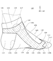
- FIG. 1 is an explanatory view of a state in which the wearing device 100 of the embodiment is worn on the foot as viewed from above.
- FIG. 2 is an explanatory view of the state in which the mounting tool 100 is mounted as viewed from the bottom.
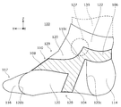
- FIG. 3 is an explanatory view of a state in which the wearing tool 100 is worn as viewed from the right side.
- FIG. 3 mainly shows the inner surface of the wearing tool 100.
- FIG. 4 is an explanatory view of a state in which the wearing tool 100 is worn as viewed from the left side.
- FIG. 4 mainly shows the outer surface of the wearing tool 100.
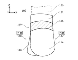
- FIG. 5 is an explanatory view of the wearing tool 100 viewed from the rear. 1 to 5 show a state in which the wearing tool 100 is worn on the left foot.
- the X-axis direction corresponds to the horizontal left-right direction
- the Y-axis direction corresponds to the horizontal front-back direction
- the Z-axis direction corresponds to the vertical up-down direction.
- the Y-axis direction and the Z-axis direction are each orthogonal to the X-axis direction.
- the X-axis direction may be referred to as the left direction or the right direction
- the Y-axis direction may be referred to as the forward direction or the rear direction
- the Z-axis direction may be referred to as the upward direction or the downward direction.
- the wearing tool 100 is viewed from above, the right side is called right and the left side is called left.
- the direction from the thumb finger 131 to the little finger 134 is referred to as outward or outside
- the direction from the little finger 134 to the thumb finger 131 is referred to as inward or inside.
- the wearing tool 100 has a sock shape that mainly accommodates the toe side from the ankle.
- the wearing tool 100 mainly includes an expansion / contraction part 110, a toe accommodation part 117, a heel accommodation part 114, a trunk part 120, and an ankle part 122.
- the expansion / contraction part 110 is a part for applying a contraction force to the foot in a direction that extends along the shape of the foot and contracts by its restoring force when worn on a person's foot.
- the stretchable part 110 will be described later.
- the trunk 120 is a cylindrical part that mainly accommodates the part between the ankle and the toe.
- a toe receiving part 117 for receiving a toe is connected to the toe side of the torso part 120.
- a tubular ankle portion 122 that accommodates at least a part of the ankle is connected to the ankle side of the trunk portion 120.
- the trunk portion 120 and the ankle portion 122 may be integrally formed, for example, by knitting a thread into a cylindrical shape.
- the wearing tool 100 includes a toe housing portion 117 for housing a toe on the toe side.
- the toe housing portion 117 includes a thumb bag 112 and a finger bag 116.
- the thumb bag 112 is a bag-like portion that houses at least a part of the thumb 131.
- the thumb bag 112 is a bag portion that houses the thumb finger 131 independently of other fingers.
- the finger bag 116 is a bag portion that accommodates four fingers from the index finger 132 to the little finger 134.
- the toe accommodating part 117 may be formed, for example, by knitting yarn in a bag shape.
- the bag storage part 114 is formed in a bag shape that can store at least a part of the bag 135, as shown in FIGS.
- the heel accommodating portion 114 may be formed, for example, by knitting yarn in a bag shape.
- the collar housing portion 114 is connected to a collar hole 120 c provided in a portion corresponding to the collar 135 of the trunk portion 120.
- the expansion / contraction part 110 includes a plurality of band-shaped parts that are band-shaped bodies that are attached to a person's foot and that extend along the shape of the foot and apply a contracting force in a direction to be contracted by the restoring force to the foot.
- the stretchable portion 110 has a first and second belt-like portions 102, 104, 106, and 106, each of which has a stretchability that abuts against a predetermined site when worn on a person's foot. , And a third belt-like portion 108.
- the wearing tool 100 can relax the extensor muscles by the expansion / contraction part 110 applying a load to the thumb flexor muscle group, and can reduce calf swelling and foot fatigue.
- the stretchable part 110 is formed from a material having a greater stretchability than the body part 120.
- the stretchable part 110 is formed from a sheet-like cloth having a larger elastic limit and a smaller elastic modulus than the body part 120.
- the stretchable part 110 may be formed of a woven fabric in which a material having a large elasticity such as rubber is woven.
- the stretchable part 110 may be formed from a fabric thicker than the body part 120.
- the first belt-like portion 102 abuts on a part extending from the base of the thumb 131 on the sole 128 side to the vicinity of the ankle 127 on the instep 129 side through the inner side portion 137 of the foot. Formed as follows.
- the first belt-like portion 102 can apply a contracting force to a portion that extends from the base of the thumb 131 on the sole 128 side to the vicinity of the lip 127 that passes the inner portion 137.
- the end of the first band 102 on the toe side is formed from the base of the index finger 132 to the base of the thumb 131.
- the width of the first belt-like portion 102 is 18 mm to 28 mm, and preferably may be formed in a range of 20 mm or more and 26 mm or less.
- the vicinity of the ankle 127 means the range of the ankle 127 and the range within 30 mm from the hem of the ankle 127.
- the second belt-like portion 104 is formed so as to come into contact with a portion extending from the base of the thumb 131 on the instep 129 side to the vicinity of the instep 127 passing through the sole 128 side and over the outer portion 138. .
- the end of the second band 104 on the toe side is formed from the base of the index finger 132 to the base of the thumb 131.
- the width of the second belt-shaped portion 104 is 11 mm to 19 mm, and preferably may be formed in a range of 13 mm or more and 17 mm or less.
- the width of the second strip 104 may be smaller than the width of the first strip 102.
- connection strip 106 (Connection strip)
- the connection strip 106 will be described mainly with reference to FIGS.
- the connecting strip 106 is formed so as to abut on a portion extending from the vicinity of the extended line of the first strip 102 to the vicinity of the extended line of the second strip 104 beyond the rear side of the foot.
- the connection strip 106 is directly or indirectly connected to the first strip 102 and the second strip 104.
- contraction force can be applied to the part where the connection band-like part 106 abuts, including the rear part of the foot.
- connection band-like portion 106 abuts the upper side of the collar 135 to a portion extending from the outer side 138 to the inner side 137.
- the width of the connection band-like portion 106 is 11 mm to 19 mm, and preferably may be formed in a range of 13 mm or more and 17 mm or less. The width of the connection strip 106 may be smaller than the width of the first strip 102.
- the stretchable portion 110 is formed without including a portion that abuts on the finger crotch 133.
- the end portions on the thumb 131 side of the first strip portion 102 and the second strip portion 104 are not connected. Accordingly, the first belt-like portion 102 and the second belt-like portion 104 are separated from each other in a portion corresponding to the finger crotch 133. The possibility of damaging the finger crotch 133 can be reduced as compared with the case where a portion that contacts the finger crotch 133 is included.
- the expansion / contraction part 110 includes a third belt-like part 108 that abuts on a region close to the outer side part 138 of the foot. As shown in FIG. 1 and FIG. 4, the third belt-shaped portion 108 abuts on a portion extending from the base of the thumb 131 on the instep 129 side to the vicinity of the lip 127 that extends beyond the outer portion 138, and the second belt-shaped portion 104. In addition, it is formed so as to be connected to the connection strip 106.
- the toe side end of the third band 108 is formed from the base of the index finger 132 to the base of the thumb 131.
- the width of the third belt-shaped portion 108 is 18 mm to 28 mm, and may be formed in a range of 20 mm or more and 26 mm or less.
- the width of the third belt-like portion 108 may be formed approximately equal to the width of the first belt-like portion 102.
- the third belt portion 108, the connection belt portion 106, and the second belt portion 104 constitute an annular belt body. From the viewpoint of reducing the burden on the finger crotch 133, the end portions on the thumb 131 side of the third belt portion 108 and the second belt portion 104 are not connected. Therefore, the third belt-like portion 108 and the second belt-like portion 104 are separated from each other in a portion corresponding to the finger crotch 133.
- each band-like portion is disposed through a different part of the foot.
- the first belt-like portion 102, the second belt-like portion 104, and the third belt-like portion 108 may be provided in parallel, but in the embodiment, these belt-like portions are used from the viewpoint of alleviating the bias of the contraction force. Are provided non-parallel.
- the first strip 102, the second strip 104, the connection strip 106, and the third strip 108 may be formed separately, but in the embodiment, these strips are integrally formed. The Compared with the case of forming separately, it is easy to ensure the strength of the joint portion, and the labor of manufacturing can be reduced.
- the first belt-like portion 102, the second belt-like portion 104, the connection belt-like portion 106, and the third belt-like portion 108 form an intersecting portion that intersects each other.
- a crossing portion is double as a fabric, the double portion becomes thick, and there is a possibility that the comfort is lowered. Therefore, in the embodiment, such an intersection portion overlaps in appearance, but the fabric has a single structure and avoids overlapping of the fabric. Therefore, such an intersecting portion is integrally formed from a cloth having the same thickness as the first belt-like portion 102.
- the first strip 102 intersects the second strip 104.
- An intersection 103 between the first belt-like portion 102 and the second belt-like portion 104 is formed, for example, on the inner side portion 137 or the sole 128 of the foot. The intersection 103 may be formed near the arch of the foot.
- the first belt-like portion 102 includes a thumb ball portion 124 that is a portion that comes into contact with at least a portion of the thumb ball 136. Compared with the case where the thumb ball 136 is detoured, the curvature of the belt-like portion can be reduced.
- the toe accommodating portion 117 has a cut portion 115 that is a cut corresponding to the finger crotch 133 between the thumb finger 131 and the index finger 132. If the stretchable part 110 is excessively arranged on the thumb 131 side of the notch part 115, the contraction force is biased toward the inner side part 137 of the foot, and there is a concern that the wearer may feel uncomfortable. Therefore, in the embodiment, the end portion 102b on the thumb 131 side of the first strip portion 102 is disposed so as to straddle the extended line Lc extending along the cutting edge of the cutting portion 115. By arranging in this way, it is possible to alleviate the bias of the contraction force.
- the end portion 108b of the third band-shaped portion 108 on the thumb 131 side is disposed so as to straddle the extended line Lc extending along the cut edge of the cut portion 115.
- the toe accommodating portion 117 may be coupled to the end portion 102b of the first band-shaped portion 102 on the thumb finger 131 side and the end portion 108b of the third band-shaped portion 108 on the thumb finger 131 side.
- FIG. 6 is a flowchart showing the manufacturing process 140 of the wearing tool 100.
- the first belt-like portion 102, the second belt-like portion 104, the connection belt-like portion 106, and the third belt-like portion 108 of the stretchable portion 110 are integrally formed by knitting, for example (S141).
- the body 120 is formed integrally with the separately formed stretchable part 110 by, for example, knitting (S142).
- the ankle portion 122 may be formed integrally with the trunk portion 120.
- the toe accommodating portion 117 including the thumb bag 112 and the finger bag 116 is formed by knitting, for example (S143).
- the heel housing portion 114 is formed, for example, by knitting (S144). (5) The toe receiving part 117 is coupled to the opening 120b on the front side of the body part 120 by, for example, sewing (S145). (6) The heel housing portion 114 is coupled to the ostium 120c of the body portion 120 by, for example, sewing (S146). Furthermore, the wearing tool 100 is manufactured through processes such as inspection and packing. In addition, as for the manufacturing process 140, the order of processes may be changed as needed, a part of processes may be deleted, a plurality of processes may be merged, divided into a plurality of processes, or another process may be added. .
- the second belt-like portion 104 is brought into contact with a portion extending from the base of the thumb 131 on the instep 129 side to the vicinity of the ankle 127 passing through the sole 128 side and over the outer side portion 138 from the base portion 137. Align. (5) The connecting strip 106 is aligned so as to abut on a portion extending from the vicinity of the extended line of the first strip 102 to the vicinity of the extended line of the second strip 104 beyond the rear side of the foot. (6) The third belt-like portion 108 is aligned so as to come into contact with a portion that extends from the base of the thumb 131 on the instep 129 side to the vicinity of the ankle 127 that passes the outer side portion 138.
- the wearing tool 100 has a first belt-like portion 102, a second belt-like portion 104, a connection belt-like portion 106, each of which has elasticity so as to abut against a predetermined portion when worn on a human foot.
- the first belt-like portion 102 is formed so as to come into contact with a portion extending from the base of the thumb 131 on the sole 128 side to the vicinity of the instep 127 passing over the inner side portion 137 of the foot
- the second belt-like portion 104 is It is formed so as to come into contact with a portion extending from the base of the thumb 131 on the instep 129 side to the vicinity of the instep 127 passing through the sole 128 side, passing through the sole 128 side, and over the outer side portion 138 of the foot.
- 106 is formed so as to come into contact with a portion that extends from the vicinity of the extension line of the first belt-like portion 102 to the vicinity of the extension line of the second belt-like portion 104 beyond the rear side of the foot.
- the contraction force can be applied from the base of the thumb 131 to the vicinity of the ankle 127 and the rear side of the foot.
- compressing the flexor flexor muscles causes relaxation of the extensors, and can reduce calf swelling and foot fatigue.
- the first belt-like portion 102 intersects with the second belt-like portion 104. According to this configuration, the intersecting portion 103 of the first belt-like portion 102 and the second belt-like portion 104 is easily adhered to the foot.
- the wearing device 100 has elasticity enough to contact a predetermined part when worn on a person's foot, and the lip 127 that extends from the base of the thumb 131 on the instep 129 side to the outer side portion 138 of the foot.
- the third belt-like portion 108 is provided which is in contact with a portion reaching the vicinity of the belt and connected to the connection belt-like portion 106. According to this configuration, since the third belt-shaped portion 108 abuts the portion beyond the outer portion 138, the contraction force of the expansion / contraction portion 110 is biased toward the inner portion 137 as compared with the case where the third belt-shaped portion is not included. Can be improved. In addition, since the third belt-like portion 108 crosses the instep 129 side in the diagonally left-right direction, the stretchable portion 110 is easily adhered to the foot.
- the first belt-like portion 102, the second belt-like portion 104, the connection belt-like portion 106, and the third belt-like portion 108 are integrally formed. According to this structure, compared with the case where these strip
- the first belt-like portion 102 includes a portion that comes into contact with at least a part of the thumb ball 136.
- belt-shaped part 102 can provide the contraction force to the thumb ball 136, and can contact
- the wearing tool 100 of the embodiment includes a toe accommodating portion 117 having a notch portion 115 corresponding to the finger crotch 133 between the thumb finger 131 and the index finger 132, and the end portion 102b on the thumb finger 131 side of the first band-like portion 102 is It arrange
- belt-shaped part 102 can be shifted outward, and the bias
- the wearing tool 100 may be formed integrally with a wear such as tights, stockings, tabi, a supporter, or an insole. Alternatively, the wearing tool 100 may be formed independently of these wearing items.
- the finger bag 116 accommodates four fingers from the forefinger 132 to the little finger 134 is not limited to this.
- a finger bag may be provided independently for each individual finger.
- the present invention can be used in the field of wearing equipment and footwear for wearing on a human foot.
Abstract
Description
しかし、従来の草鞋は、足に装着するために多大な手間がかかり、また不慣れな場合には足に絞めた紐がその当接部位を傷付けるおそれもある。これらのことは草鞋の特性を履物として実用化することの障害となっていた。
このことから、発明者は草鞋の持つ特性を例えば靴下などの足にまとう履物に再現することが課題であると認識した
実施の形態は、このような認識に基づいて案出されたもので、以下にその具体的な構成を説明する。
以下、本発明を好適な実施の形態をもとに各図面を参照しながら説明する。実施の形態、変形例では、同一または同等の構成要素、部材には、同一の符号を付するものとし、適宜重複した説明は省略する。また、各図面における部材の寸法は、理解を容易にするために適宜拡大、縮小して示される。また、各図面において実施の形態を説明する上で重要ではない部材の一部は省略して表示する。
また、第1、第2などの序数を含む用語は多様な構成要素を説明するために用いられるが、この用語は一つの構成要素を他の構成要素から区別する目的でのみ用いられ、この用語によって構成要素が限定されるものではない。
装着具100は爪先側で足の指を収容するための爪先収容部117を備える。図1、図2に示すように、爪先収容部117は拇指袋112と指袋116とを含む。拇指袋112は、拇指131の少なくとも一部を収容する袋状の部分である。拇指袋112は拇指131を他の指から独立して収容する袋部である。指袋116は人差指132から小指134までの4本の指を収容する袋部である。爪先収容部117は、例えば糸を袋状に編成することによって形成されてもよい。
伸縮部110は、人の足に装着されることで、足形状に沿って伸び、その復元力によって縮む方向の収縮力を足に付与する帯状体である帯状部を複数含む。具体的には、伸縮部110は、人の足に装着したときにそれぞれ所定部位に当接する程度の伸縮性を有する、第1帯状部102と、第2帯状部104と、接続帯状部106と、第3帯状部108と、を含む。装着具100は、伸縮部110が拇指屈筋群に荷重を加えることで、伸筋に弛緩をもたらし、ふくらはぎのむくみや足の疲労を緩和することができる。伸縮部110は胴部120より大きな伸縮性を有する材料から形成される。特に、伸縮部110は胴部120より弾性限界が大きく弾性率が小さいシート状の生地から形成される。伸縮部110は、例えばゴムなど大きな弾性を有する素材が織り込まれた織物から形成されてもよい。伸縮部110は胴部120より厚い生地から形成されてもよい。
図1~図5に示すように、第1帯状部102は、足裏128側の拇指131の付け根から足の内側部137を越えて足甲129側のくるぶし127の近傍に至る部位に当接するように形成される。第1帯状部102は、足裏128側の拇指131の付け根から内側部137を越えてくるぶし127の近傍に至る部位に収縮力を付与することができる。特に、第1帯状部102の爪先側の端部は人差指132の付け根から拇指131の付け根にかけて形成される。一例として、第1帯状部102の幅は18mmから28mmであり、好ましくは20mm以上で26mm以下の範囲に形成されてもよい。なお、この明細書においてくるぶし127の近傍とは、くるぶし127の範囲およびくるぶし127の裾から周囲30mm以内の範囲をいう。
第2帯状部104は、足甲129側の拇指131の付け根から内側部137を越えて足裏128側を通り外側部138を越えてくるぶし127の近傍に至る部位に当接するように形成される。特に、第2帯状部104の爪先側の端部は人差指132の付け根から拇指131の付け根にかけて形成される。第2帯状部104を含むことで、足甲129側の拇指131の付け根から内側部137を越えて足裏128側を通り外側部138を越えてくるぶし127の近傍に至る部位に収縮力を付与することができる。一例として、第2帯状部104の幅は11mmから19mmであり、好ましくは13mm以上で17mm以下の範囲に形成されてもよい。第2帯状部104の幅は第1帯状部102の幅より小さく形成されてもよい。
主に図3~図5を参照して接続帯状部106を説明する。実施の形態において、接続帯状部106は、第1帯状部102の延長線上の近傍から足の後側を越えて第2帯状部104の延長線上の近傍に至る部位に当接するように形成される。特に、接続帯状部106は第1帯状部102と第2帯状部104とに直接的または間接的に繋げられる。接続帯状部106を含むことで、足の後側の部位を含めて接続帯状部106が当接する部位に収縮力を付与することができる。また、第1帯状部102および第2帯状部104と一体に繋がることで、これらの帯状部が当接する部位に連続して収縮力を付与することができる。接続帯状部106は、例えばくるぶし127の近傍の領域で踵135の上側を外側部138から内側部137にわたる部位に当接する。一例として、接続帯状部106の幅は11mmから19mmであり、好ましくは13mm以上で17mm以下の範囲に形成されてもよい。接続帯状部106の幅は第1帯状部102の幅より小さく形成されてもよい。
収縮力が足の内側部137側に過度に偏ると装着者に違和感を与える懸念がある。そこで、実施の形態では、伸縮部110は足の外側部138側に寄った領域に当接する第3帯状部108を含む。図1、図4に示すように、第3帯状部108は、足甲129側の拇指131の付け根から外側部138を越えてくるぶし127の近傍に至る部位に当接して、第2帯状部104及び接続帯状部106に繋げられるように形成される。実施の形態では、特に、第3帯状部108の爪先側の端部は人差指132の付け根から拇指131の付け根にかけて形成される。一例として、第3帯状部108の幅は18mmから28mmであり、好ましくは20mm以上で26mm以下の範囲に形成されてもよい。第3帯状部108の幅は第1帯状部102の幅と略等しく形成されてもよい。
(1)例えば編成によって、伸縮部110の第1帯状部102と、第2帯状部104と、接続帯状部106と、第3帯状部108とを一体に形成する(S141)。
(2)例えば編成によって、別に形成された伸縮部110と一体に胴部120を形成する(S142)。この際、足首部122は胴部120と一体に形成してもよい。
(3)例えば編成によって、拇指袋112と指袋116とを含む爪先収容部117を形成する(S143)。
(4)例えば編成によって、踵収容部114を形成する(S144)。
(5)例えば縫合によって、胴部120の前側の開口120bに爪先収容部117を結合する(S145)。
(6)例えば縫合によって、胴部120の踵孔120cに踵収容部114を結合する(S146)。
さらに検査や梱包などの工程を経て装着具100が製造される。なお、製造工程140は、必要に応じて工程の順序を入れ替えてもよく、一部の工程を削除し、複数の工程を併合し、複数の工程に分割しあるいは別工程を追加してもよい。
(1)拇指袋112を拇指131に被せ、伸縮部110の前側の端部110bを拇指131および人差指132側にセットする。
(2)踵収容部114を踵135に被せ、伸縮部110の後側の端部110cをくるぶし127側にセットする。
(3)第1帯状部102を、足裏128側の拇指131の付け根から足の内側部137を越えて足甲129側のくるぶし127の近傍に至る部位に当接するように位置合わせする。
(4)第2帯状部104を、足甲129側の拇指131の付け根から内側部137を越えて足裏128側を通り外側部138を越えてくるぶし127の近傍に至る部位に当接するように位置合わせする。
(5)接続帯状部106を、第1帯状部102の延長線上の近傍から足の後側を越えて第2帯状部104の延長線上の近傍に至る部位に当接するように位置合わせする。
(6)第3帯状部108を、足甲129側の拇指131の付け根から外側部138を越えてくるぶし127の近傍に至る部位に当接するように位置合わせする。
実施の形態の装着具100を、このように使用することで、拇指屈筋群を圧縮して伸筋群の弛緩をもたらし、ふくらはぎのむくみや足の疲労を緩和することができる。
実施の形態の装着具100は、人の足に装着したときにそれぞれ所定部位に当接する程度の伸縮性を有する、第1帯状部102と、第2帯状部104と、接続帯状部106と、を備え、第1帯状部102は、足裏128側の拇指131の付け根から足の内側部137を越えてくるぶし127の近傍に至る部位に当接するように形成され、第2帯状部104は、足甲129側の拇指131の付け根から足の内側部137を越えて足裏128側を通り足の外側部138を越えてくるぶし127の近傍に至る部位に当接するように形成され、接続帯状部106は、第1帯状部102の延長線上の近傍から足の後側を越えて第2帯状部104の延長線上の近傍に至る部位に当接するように形成される。この構成によれば、容易に装着できる装着具に、歩行に適した草鞋に類似する特性を再現することができる。特に拇指131の付け根からくるぶし127の近傍及び足の後側にかけて収縮力を付与できる。この結果、拇指屈筋群を圧縮することで伸筋群の弛緩をもたらし、ふくらはぎのむくみや足の疲労を緩和することができる。
以下、変形例について説明する。変形例の説明では、実施の形態と同一または同等の構成要素、部材には、同一の符号を付する。実施の形態と重複する説明を適宜省略し、実施の形態と相違する構成について重点的に説明する。
Claims (7)
- 人の足に装着したときにそれぞれ所定部位に当接する程度の伸縮性を有する、第1帯状部と、第2帯状部と、接続帯状部と、を備え、
前記第1帯状部は、足裏側の拇指の付け根から足の内側部を越えてくるぶしの近傍に至る部位に当接するように形成され、
前記第2帯状部は、足甲側の拇指の付け根から足の内側部を越えて足裏側を通り足の外側部を越えてくるぶしの近傍に至る部位に当接するように形成され、
前記接続帯状部は、前記第1帯状部の延長線上の近傍から足の後側を越えて前記第2帯状部の延長線上の近傍に至る部位に当接するように形成されることを特徴とする装着具。 - 前記第1帯状部は前記第2帯状部と交差することを特徴とする請求項1に記載の装着具。
- 人の足に装着したときに所定部位に当接する程度の伸縮性を有し、足甲側の拇指の付け根から足の外側部を越えてくるぶしの近傍に至る部位に当接するように形成される第3帯状部を備えることを特徴とする請求項1または2に記載の装着具。
- 前記第1帯状部と、前記第2帯状部と、前記接続帯状部と、前記第3帯状部と、は一体に形成されることを特徴とする請求項3に記載の装着具。
- 前記第1帯状部は拇指球の少なくとも一部に当接する部分を含むことを特徴とする請求項1から4のいずれかに記載の装着具。
- 拇指と人差指の間の指股に対応する切込部を有する爪先収容部を備え、
前記第1帯状部の拇指側の端部は前記切込部の切込み縁に沿って延長した延長線を跨ぐように配置されることを特徴とする請求項1から5のいずれかに記載の装着具。 - 請求項1から6のいずれかに記載の装着具が一体に編成される履物。
Priority Applications (7)
| Application Number | Priority Date | Filing Date | Title |
|---|---|---|---|
| KR1020177033834A KR102034943B1 (ko) | 2016-07-15 | 2017-01-17 | 장착구, 신발 |
| SG11201709434WA SG11201709434WA (en) | 2016-07-15 | 2017-01-17 | Wearing article and footwear |
| CA2985562A CA2985562C (en) | 2016-07-15 | 2017-01-17 | Wearing article and footwear |
| JP2017102468A JP6190558B1 (ja) | 2016-07-15 | 2017-05-24 | 装着具、履物 |
| TW106122405A TWI631912B (zh) | 2016-07-15 | 2017-07-04 | 著裝用具、鞋襪類 |
| JP2017150875A JP2018016934A (ja) | 2016-07-15 | 2017-08-03 | 装着具、履物 |
| US15/815,388 US20180070660A1 (en) | 2016-07-15 | 2017-11-16 | Wearing article and footwear |
Applications Claiming Priority (2)
| Application Number | Priority Date | Filing Date | Title |
|---|---|---|---|
| JP2016140850 | 2016-07-15 | ||
| JP2016-140850 | 2016-07-15 |
Related Child Applications (1)
| Application Number | Title | Priority Date | Filing Date |
|---|---|---|---|
| US15/815,388 Continuation US20180070660A1 (en) | 2016-07-15 | 2017-11-16 | Wearing article and footwear |
Publications (1)
| Publication Number | Publication Date |
|---|---|
| WO2018012010A1 true WO2018012010A1 (ja) | 2018-01-18 |
Family
ID=60952942
Family Applications (1)
| Application Number | Title | Priority Date | Filing Date |
|---|---|---|---|
| PCT/JP2017/001329 WO2018012010A1 (ja) | 2016-07-15 | 2017-01-17 | 装着具、履物 |
Country Status (7)
| Country | Link |
|---|---|
| US (1) | US20180070660A1 (ja) |
| JP (1) | JP2018016934A (ja) |
| KR (1) | KR102034943B1 (ja) |
| CA (1) | CA2985562C (ja) |
| SG (1) | SG11201709434WA (ja) |
| TW (1) | TWI631912B (ja) |
| WO (1) | WO2018012010A1 (ja) |
Cited By (1)
| Publication number | Priority date | Publication date | Assignee | Title |
|---|---|---|---|---|
| RU197002U1 (ru) * | 2020-01-31 | 2020-03-24 | Мария Сергеевна Михайлова | Носок с вшитым в него противовальгусным корсетом |
Families Citing this family (4)
| Publication number | Priority date | Publication date | Assignee | Title |
|---|---|---|---|---|
| JP6758347B2 (ja) * | 2018-07-18 | 2020-09-23 | 且義 石本 | 靴下 |
| TWI725377B (zh) * | 2019-02-01 | 2021-04-21 | 國立雲林科技大學 | 多功能運動襪構造 |
| JP7007511B1 (ja) * | 2021-05-28 | 2022-02-14 | 西垣靴下株式会社 | 靴下 |
| JP7397259B2 (ja) * | 2021-10-22 | 2023-12-13 | 株式会社スペーレン | 矯正用靴下、及び、足矯正用サポータ |
Citations (4)
| Publication number | Priority date | Publication date | Assignee | Title |
|---|---|---|---|---|
| JP2006348406A (ja) * | 2005-06-14 | 2006-12-28 | Wacoal Corp | 足コンディショニングウエア |
| JP2012046838A (ja) * | 2010-08-25 | 2012-03-08 | Goldwin Inc | 靴下 |
| JP2012072505A (ja) * | 2009-12-21 | 2012-04-12 | Yumi Mitsui | 靴下 |
| JP2014527127A (ja) * | 2011-08-25 | 2014-10-09 | エクス−テクノロジー スイス ゲゼルシャフト ミット ベシュレンクテル ハフツング | 靴下 |
Family Cites Families (20)
| Publication number | Priority date | Publication date | Assignee | Title |
|---|---|---|---|---|
| US1566063A (en) * | 1922-11-10 | 1925-12-15 | Walter M Barry | Foot corrector |
| US1788852A (en) * | 1930-01-11 | 1931-01-13 | Gilbert V Arthur | Orthopedic appliance |
| US1899092A (en) * | 1931-01-20 | 1933-02-28 | Margaret M Hogan | Bunion corrective device |
| US1930188A (en) * | 1931-03-23 | 1933-10-10 | Gilbert V Arthur | Orthopedic brace |
| US4637381A (en) * | 1985-06-03 | 1987-01-20 | Institute For Gravitational Strain Pathology, Inc. | Foot supporting device |
| KR100420504B1 (ko) * | 2001-08-18 | 2004-03-09 | 김명순 | 엄지발가락 교정기 및 그 생산방법 |
| US6800063B2 (en) * | 2002-04-02 | 2004-10-05 | Kazuo Iwata | Foot stimulation tool |
| USD499807S1 (en) * | 2004-02-13 | 2004-12-14 | Adidas International Marketing B.V. | Foot strap |
| USD551430S1 (en) * | 2005-10-24 | 2007-09-25 | Pointe Noir Pty. Ltd. | Dance footwear |
| DE202006001381U1 (de) * | 2006-01-27 | 2006-06-22 | X-Technology Swiss Gmbh | Socke |
| ITPD20070052A1 (it) * | 2007-02-20 | 2008-08-21 | Luca Carlo De | Calza o calzino rinforzato per il trattamento preventivo e/o terapeutico dell'alluce valgo |
| US8856968B2 (en) | 2009-11-25 | 2014-10-14 | PTX Performance Products, Inc. | Foot stabilizer socks and stabilizer pads therefor |
| DE202010013071U1 (de) * | 2010-12-07 | 2011-02-17 | Wendling, Dietrich, Dr. med. | Fußgewölbe-Stützstrumpf |
| KR200457048Y1 (ko) | 2011-03-08 | 2011-12-02 | 홍정환 | 무지외반증 교정용 신발 |
| TWM446508U (zh) * | 2012-09-06 | 2013-02-11 | Titan Sport Tech Co Ltd | 壓力襪 |
| TWM456098U (zh) * | 2013-01-11 | 2013-07-01 | Xia Liu | 襪子 |
| GB201306884D0 (en) * | 2013-04-16 | 2013-05-29 | Dm Orthotics Ltd | Orthotic foot support |
| WO2015181932A1 (ja) * | 2014-05-29 | 2015-12-03 | 有限会社Opti | 足関節サポーター |
| CN205125062U (zh) * | 2015-10-22 | 2016-04-06 | 江阴市超宇针织有限公司 | 一种脚趾保护袜 |
| USD821068S1 (en) * | 2016-10-19 | 2018-06-26 | Byron Coleman | Shoe |
-
2017
- 2017-01-17 KR KR1020177033834A patent/KR102034943B1/ko active IP Right Grant
- 2017-01-17 WO PCT/JP2017/001329 patent/WO2018012010A1/ja active Application Filing
- 2017-01-17 SG SG11201709434WA patent/SG11201709434WA/en unknown
- 2017-01-17 CA CA2985562A patent/CA2985562C/en active Active
- 2017-07-04 TW TW106122405A patent/TWI631912B/zh active
- 2017-08-03 JP JP2017150875A patent/JP2018016934A/ja active Pending
- 2017-11-16 US US15/815,388 patent/US20180070660A1/en not_active Abandoned
Patent Citations (4)
| Publication number | Priority date | Publication date | Assignee | Title |
|---|---|---|---|---|
| JP2006348406A (ja) * | 2005-06-14 | 2006-12-28 | Wacoal Corp | 足コンディショニングウエア |
| JP2012072505A (ja) * | 2009-12-21 | 2012-04-12 | Yumi Mitsui | 靴下 |
| JP2012046838A (ja) * | 2010-08-25 | 2012-03-08 | Goldwin Inc | 靴下 |
| JP2014527127A (ja) * | 2011-08-25 | 2014-10-09 | エクス−テクノロジー スイス ゲゼルシャフト ミット ベシュレンクテル ハフツング | 靴下 |
Cited By (1)
| Publication number | Priority date | Publication date | Assignee | Title |
|---|---|---|---|---|
| RU197002U1 (ru) * | 2020-01-31 | 2020-03-24 | Мария Сергеевна Михайлова | Носок с вшитым в него противовальгусным корсетом |
Also Published As
| Publication number | Publication date |
|---|---|
| US20180070660A1 (en) | 2018-03-15 |
| JP2018016934A (ja) | 2018-02-01 |
| TW201803473A (zh) | 2018-02-01 |
| KR102034943B1 (ko) | 2019-10-21 |
| CA2985562A1 (en) | 2018-01-15 |
| KR20180020960A (ko) | 2018-02-28 |
| CA2985562C (en) | 2019-09-24 |
| SG11201709434WA (en) | 2018-05-30 |
| TWI631912B (zh) | 2018-08-11 |
Similar Documents
| Publication | Publication Date | Title |
|---|---|---|
| WO2018012010A1 (ja) | 装着具、履物 | |
| JP5165122B2 (ja) | フートウェア | |
| JP5102611B2 (ja) | 靴下 | |
| US10398584B2 (en) | Ankle supporter | |
| US9192200B2 (en) | Foot joint supporter | |
| JP2007332470A (ja) | 靴下又は筒状の下肢用サポーター | |
| JP2013530734A (ja) | 矯正用足指靴下 | |
| JP2007332469A (ja) | 靴下又は筒状の下肢用サポーター | |
| EP2636779B1 (en) | Sock | |
| JP5411083B2 (ja) | レッグウェア | |
| JP3119255U (ja) | 靴下 | |
| JP4294520B2 (ja) | 脚部サポート用衣類 | |
| JP6190558B1 (ja) | 装着具、履物 | |
| KR20180040789A (ko) | 다리 보호용 압박 타이즈 | |
| JP7217912B2 (ja) | 靴下型サポーター | |
| JP3165090U (ja) | 靴下又は筒状の下肢用サポーター | |
| JP2010077574A (ja) | 下肢用衣料 | |
| JP5398874B2 (ja) | 外反母趾矯正用具 | |
| JP2015089973A (ja) | 歩行補正靴下 | |
| JP6615239B2 (ja) | 足関節矯正用靴下 | |
| JP3119498U (ja) | つまずき防止靴下 | |
| JP2013076175A (ja) | 足趾トレーニング用靴下 | |
| JP6699976B2 (ja) | 運動用のウェアおよびその使用方法 | |
| JP6052007B2 (ja) | 足被覆体および足サポート部材 | |
| JP6431389B2 (ja) | 足用サポータ |
Legal Events
| Date | Code | Title | Description |
|---|---|---|---|
| ENP | Entry into the national phase |
Ref document number: 2985562 Country of ref document: CA Kind code of ref document: A |
|
| ENP | Entry into the national phase |
Ref document number: 20177033834 Country of ref document: KR Kind code of ref document: A |
|
| WWE | Wipo information: entry into national phase |
Ref document number: 11201709434W Country of ref document: SG |
|
| 121 | Ep: the epo has been informed by wipo that ep was designated in this application |
Ref document number: 17827145 Country of ref document: EP Kind code of ref document: A1 |
|
| NENP | Non-entry into the national phase |
Ref country code: DE |
|
| 122 | Ep: pct application non-entry in european phase |
Ref document number: 17827145 Country of ref document: EP Kind code of ref document: A1 |