WO2018011854A1 - ミスト塗布成膜装置及びミスト塗布成膜方法 - Google Patents
ミスト塗布成膜装置及びミスト塗布成膜方法 Download PDFInfo
- Publication number
- WO2018011854A1 WO2018011854A1 PCT/JP2016/070424 JP2016070424W WO2018011854A1 WO 2018011854 A1 WO2018011854 A1 WO 2018011854A1 JP 2016070424 W JP2016070424 W JP 2016070424W WO 2018011854 A1 WO2018011854 A1 WO 2018011854A1
- Authority
- WO
- WIPO (PCT)
- Prior art keywords
- mist
- raw material
- material solution
- substrate
- coating film
- Prior art date
- Legal status (The legal status is an assumption and is not a legal conclusion. Google has not performed a legal analysis and makes no representation as to the accuracy of the status listed.)
- Ceased
Links
Images



Classifications
-
- B—PERFORMING OPERATIONS; TRANSPORTING
- B05—SPRAYING OR ATOMISING IN GENERAL; APPLYING FLUENT MATERIALS TO SURFACES, IN GENERAL
- B05B—SPRAYING APPARATUS; ATOMISING APPARATUS; NOZZLES
- B05B17/00—Apparatus for spraying or atomising liquids or other fluent materials, not covered by the preceding groups
- B05B17/04—Apparatus for spraying or atomising liquids or other fluent materials, not covered by the preceding groups operating with special methods
- B05B17/06—Apparatus for spraying or atomising liquids or other fluent materials, not covered by the preceding groups operating with special methods using ultrasonic or other kinds of vibrations
-
- B—PERFORMING OPERATIONS; TRANSPORTING
- B05—SPRAYING OR ATOMISING IN GENERAL; APPLYING FLUENT MATERIALS TO SURFACES, IN GENERAL
- B05D—PROCESSES FOR APPLYING FLUENT MATERIALS TO SURFACES, IN GENERAL
- B05D1/00—Processes for applying liquids or other fluent materials
- B05D1/02—Processes for applying liquids or other fluent materials performed by spraying
-
- B—PERFORMING OPERATIONS; TRANSPORTING
- B05—SPRAYING OR ATOMISING IN GENERAL; APPLYING FLUENT MATERIALS TO SURFACES, IN GENERAL
- B05B—SPRAYING APPARATUS; ATOMISING APPARATUS; NOZZLES
- B05B1/00—Nozzles, spray heads or other outlets, with or without auxiliary devices such as valves, heating means
- B05B1/02—Nozzles, spray heads or other outlets, with or without auxiliary devices such as valves, heating means designed to produce a jet, spray, or other discharge of particular shape or nature, e.g. in single drops, or having an outlet of particular shape
- B05B1/04—Nozzles, spray heads or other outlets, with or without auxiliary devices such as valves, heating means designed to produce a jet, spray, or other discharge of particular shape or nature, e.g. in single drops, or having an outlet of particular shape in flat form, e.g. fan-like, sheet-like
- B05B1/044—Slits, e.g. narrow openings defined by two straight and parallel lips; Elongated outlets for producing very wide discharges, e.g. fluid curtains
-
- B—PERFORMING OPERATIONS; TRANSPORTING
- B05—SPRAYING OR ATOMISING IN GENERAL; APPLYING FLUENT MATERIALS TO SURFACES, IN GENERAL
- B05B—SPRAYING APPARATUS; ATOMISING APPARATUS; NOZZLES
- B05B1/00—Nozzles, spray heads or other outlets, with or without auxiliary devices such as valves, heating means
- B05B1/02—Nozzles, spray heads or other outlets, with or without auxiliary devices such as valves, heating means designed to produce a jet, spray, or other discharge of particular shape or nature, e.g. in single drops, or having an outlet of particular shape
- B05B1/10—Nozzles, spray heads or other outlets, with or without auxiliary devices such as valves, heating means designed to produce a jet, spray, or other discharge of particular shape or nature, e.g. in single drops, or having an outlet of particular shape in the form of a fine jet, e.g. for use in wind-screen washers
-
- B—PERFORMING OPERATIONS; TRANSPORTING
- B05—SPRAYING OR ATOMISING IN GENERAL; APPLYING FLUENT MATERIALS TO SURFACES, IN GENERAL
- B05B—SPRAYING APPARATUS; ATOMISING APPARATUS; NOZZLES
- B05B13/00—Machines or plants for applying liquids or other fluent materials to surfaces of objects or other work by spraying, not covered by groups B05B1/00 - B05B11/00
-
- B—PERFORMING OPERATIONS; TRANSPORTING
- B05—SPRAYING OR ATOMISING IN GENERAL; APPLYING FLUENT MATERIALS TO SURFACES, IN GENERAL
- B05B—SPRAYING APPARATUS; ATOMISING APPARATUS; NOZZLES
- B05B15/00—Details of spraying plant or spraying apparatus not otherwise provided for; Accessories
-
- B—PERFORMING OPERATIONS; TRANSPORTING
- B05—SPRAYING OR ATOMISING IN GENERAL; APPLYING FLUENT MATERIALS TO SURFACES, IN GENERAL
- B05B—SPRAYING APPARATUS; ATOMISING APPARATUS; NOZZLES
- B05B17/00—Apparatus for spraying or atomising liquids or other fluent materials, not covered by the preceding groups
- B05B17/04—Apparatus for spraying or atomising liquids or other fluent materials, not covered by the preceding groups operating with special methods
- B05B17/06—Apparatus for spraying or atomising liquids or other fluent materials, not covered by the preceding groups operating with special methods using ultrasonic or other kinds of vibrations
- B05B17/0607—Apparatus for spraying or atomising liquids or other fluent materials, not covered by the preceding groups operating with special methods using ultrasonic or other kinds of vibrations generated by electrical means, e.g. piezoelectric transducers
- B05B17/0615—Apparatus for spraying or atomising liquids or other fluent materials, not covered by the preceding groups operating with special methods using ultrasonic or other kinds of vibrations generated by electrical means, e.g. piezoelectric transducers spray being produced at the free surface of the liquid or other fluent material in a container and subjected to the vibrations
-
- B—PERFORMING OPERATIONS; TRANSPORTING
- B05—SPRAYING OR ATOMISING IN GENERAL; APPLYING FLUENT MATERIALS TO SURFACES, IN GENERAL
- B05B—SPRAYING APPARATUS; ATOMISING APPARATUS; NOZZLES
- B05B7/00—Spraying apparatus for discharge of liquids or other fluent materials from two or more sources, e.g. of liquid and air, of powder and gas
- B05B7/0012—Apparatus for achieving spraying before discharge from the apparatus
-
- B—PERFORMING OPERATIONS; TRANSPORTING
- B05—SPRAYING OR ATOMISING IN GENERAL; APPLYING FLUENT MATERIALS TO SURFACES, IN GENERAL
- B05B—SPRAYING APPARATUS; ATOMISING APPARATUS; NOZZLES
- B05B7/00—Spraying apparatus for discharge of liquids or other fluent materials from two or more sources, e.g. of liquid and air, of powder and gas
- B05B7/24—Spraying apparatus for discharge of liquids or other fluent materials from two or more sources, e.g. of liquid and air, of powder and gas with means, e.g. a container, for supplying liquid or other fluent material to a discharge device
- B05B7/26—Apparatus in which liquids or other fluent materials from different sources are brought together before entering the discharge device
-
- B—PERFORMING OPERATIONS; TRANSPORTING
- B05—SPRAYING OR ATOMISING IN GENERAL; APPLYING FLUENT MATERIALS TO SURFACES, IN GENERAL
- B05B—SPRAYING APPARATUS; ATOMISING APPARATUS; NOZZLES
- B05B9/00—Spraying apparatus for discharge of liquids or other fluent material, without essentially mixing with gas or vapour
- B05B9/03—Spraying apparatus for discharge of liquids or other fluent material, without essentially mixing with gas or vapour characterised by means for supplying liquid or other fluent material
-
- B—PERFORMING OPERATIONS; TRANSPORTING
- B05—SPRAYING OR ATOMISING IN GENERAL; APPLYING FLUENT MATERIALS TO SURFACES, IN GENERAL
- B05D—PROCESSES FOR APPLYING FLUENT MATERIALS TO SURFACES, IN GENERAL
- B05D1/00—Processes for applying liquids or other fluent materials
- B05D1/02—Processes for applying liquids or other fluent materials performed by spraying
- B05D1/12—Applying particulate materials
-
- B—PERFORMING OPERATIONS; TRANSPORTING
- B05—SPRAYING OR ATOMISING IN GENERAL; APPLYING FLUENT MATERIALS TO SURFACES, IN GENERAL
- B05D—PROCESSES FOR APPLYING FLUENT MATERIALS TO SURFACES, IN GENERAL
- B05D7/00—Processes, other than flocking, specially adapted for applying liquids or other fluent materials to particular surfaces or for applying particular liquids or other fluent materials
- B05D7/24—Processes, other than flocking, specially adapted for applying liquids or other fluent materials to particular surfaces or for applying particular liquids or other fluent materials for applying particular liquids or other fluent materials
-
- B—PERFORMING OPERATIONS; TRANSPORTING
- B05—SPRAYING OR ATOMISING IN GENERAL; APPLYING FLUENT MATERIALS TO SURFACES, IN GENERAL
- B05D—PROCESSES FOR APPLYING FLUENT MATERIALS TO SURFACES, IN GENERAL
- B05D2601/00—Inorganic fillers
- B05D2601/20—Inorganic fillers used for non-pigmentation effect
-
- B—PERFORMING OPERATIONS; TRANSPORTING
- B05—SPRAYING OR ATOMISING IN GENERAL; APPLYING FLUENT MATERIALS TO SURFACES, IN GENERAL
- B05D—PROCESSES FOR APPLYING FLUENT MATERIALS TO SURFACES, IN GENERAL
- B05D3/00—Pretreatment of surfaces to which liquids or other fluent materials are to be applied; After-treatment of applied coatings, e.g. intermediate treating of an applied coating preparatory to subsequent applications of liquids or other fluent materials
- B05D3/02—Pretreatment of surfaces to which liquids or other fluent materials are to be applied; After-treatment of applied coatings, e.g. intermediate treating of an applied coating preparatory to subsequent applications of liquids or other fluent materials by baking
- B05D3/0254—After-treatment
-
- C—CHEMISTRY; METALLURGY
- C23—COATING METALLIC MATERIAL; COATING MATERIAL WITH METALLIC MATERIAL; CHEMICAL SURFACE TREATMENT; DIFFUSION TREATMENT OF METALLIC MATERIAL; COATING BY VACUUM EVAPORATION, BY SPUTTERING, BY ION IMPLANTATION OR BY CHEMICAL VAPOUR DEPOSITION, IN GENERAL; INHIBITING CORROSION OF METALLIC MATERIAL OR INCRUSTATION IN GENERAL
- C23C—COATING METALLIC MATERIAL; COATING MATERIAL WITH METALLIC MATERIAL; SURFACE TREATMENT OF METALLIC MATERIAL BY DIFFUSION INTO THE SURFACE, BY CHEMICAL CONVERSION OR SUBSTITUTION; COATING BY VACUUM EVAPORATION, BY SPUTTERING, BY ION IMPLANTATION OR BY CHEMICAL VAPOUR DEPOSITION, IN GENERAL
- C23C16/00—Chemical coating by decomposition of gaseous compounds, without leaving reaction products of surface material in the coating, i.e. chemical vapour deposition [CVD] processes
- C23C16/44—Chemical coating by decomposition of gaseous compounds, without leaving reaction products of surface material in the coating, i.e. chemical vapour deposition [CVD] processes characterised by the method of coating
- C23C16/4415—Acoustic wave CVD
Definitions
- the present invention relates to a mist coating film forming apparatus and a mist coating film forming method for forming a thin film on a substrate to be formed by misting a raw material solution, which is a nanoparticle dispersion solution or a nanofiber dispersion solution, with ultrasonic waves. Is.
- mist CVD film forming method as one method for forming a metal oxide thin film from an organometallic compound under atmospheric pressure.
- the mist CVD film formation system consists of two parts. One is a first part in which a raw material solution in which an organometallic compound is dissolved is misted with an ultrasonic vibrator and the raw material solution mist is supplied with a carrier gas. The other is that the mist supplied by the carrier gas is sprayed from the film forming head onto the surface of the substrate, and the raw material solution mist vaporized on the surface of the substrate reacts with the oxidant ozone or water vapor while heating the substrate. This is a second part for forming a metal oxide film.
- the mist CVD film forming method is a method of forming a metal oxide thin film from a raw material solution in which an organometallic compound is dissolved through a chemical reaction.
- the CVD film forming method is disclosed in, for example, Patent Document 1 and Non-Patent Document 1.
- the conventional mist CVD film forming apparatus disclosed in Patent Document 1 or Non-Patent Document 1 mists a raw material solution in which an organometallic compound is dissolved with an ultrasonic vibrator, and transports the mist to a film forming head with a transport gas.
- the mist supplied from the film formation head is vaporized, and the vaporized raw material on the heated film formation substrate reacts with the oxidizing agent to form a metal oxide film.
- the mist CVD film forming method is a method of forming a metal oxide film such as zinc oxide or alumina by a chemical method from an organic metal compound such as diethyl zinc or aluminum acetylacetonate.
- the conventional mist CVD film formation method can form a metal oxide thin film.
- a functional thin film such as a nanoparticle thin film or nanofiber thin film is formed from a raw material solution that is a nanoparticle dispersion solution or a nanofiber dispersion solution.
- a raw material solution that is a nanoparticle dispersion solution or a nanofiber dispersion solution.
- An object of the present invention is to solve the above problems and to provide a mist coating film forming apparatus and a mist coating film forming method capable of forming a thin film having functionality other than a metal oxide film.
- the mist coating film forming apparatus includes a raw material solution mist forming mechanism that mists a raw material solution in an atomization container by using an ultrasonic vibrator to obtain a liquid raw material solution mist in a droplet form, A nanoparticle dispersion solution or nanofiber dispersion solution containing a predetermined raw material, having a mounting portion for mounting a substrate to be deposited, supplying the raw material solution mist to the substrate, and a surface of the substrate The raw material solution mist is applied on the surface of the substrate to form a raw material solution liquid film, and the raw material solution liquid film formed on the surface of the substrate is baked and dried. And a firing / drying mechanism for forming a thin film using the predetermined raw material contained in the raw material solution liquid film as a constituent material on the surface of the substrate.
- the mist coating film forming apparatus is a mist coating mechanism for coating a raw material solution mist by coating a raw material solution mist on a surface of a substrate, and then forming a raw material solution liquid film by a baking / drying mechanism.
- a thin film containing a predetermined raw material is formed on the surface of the substrate by baking and drying.
- a nanoparticle dispersion solution or a nanofiber dispersion solution is used as a raw material solution.
- the mist coating film forming apparatus of the present invention forms a thin film with a uniform material on the surface of the substrate with a predetermined raw material contained in the nanoparticle dispersion solution or nanofiber dispersion solution. can do.
- FIG. 1 is an explanatory view schematically showing a configuration of a mist coating film forming apparatus according to an embodiment of the present invention.
- the mist coating film forming apparatus of the first embodiment has a raw material solution mist forming mechanism 50, a mist coating mechanism 70, and a baking / drying mechanism 90 as main components.
- the raw material solution mist generating mechanism 50 mists the raw material solution 5 charged into the atomization vessel 4 using the ultrasonic vibrator 1 that generates ultrasonic waves into droplets having a narrow particle size distribution and a central particle size of about 4 ⁇ m.
- a raw material solution mist generating process for generating the raw material solution mist 6 is executed.
- the raw material solution mist 6 is conveyed to the mist coating mechanism 70 via the mist supply line 22 by the carrier gas supplied from the carrier gas supply unit 16.
- the mist application mechanism 70 receives the raw material solution mist 6 from the mist supply line 22 and is placed on the surface of the substrate 9 (film formation target substrate) placed on the moving stage 10 (placement unit) from the mist application head 8.
- the raw material solution mist 6 is coated on the surface of the substrate 9 (coat), and a raw material for forming an ultrathin raw material solution liquid film (raw material solution liquid film) on the surface of the substrate 9 Perform solution mist coating processing (mist coating processing).
- the baking / drying mechanism 90 bakes and dries the substrate 9 on the surface of which the thin raw material solution liquid film is formed on the hot plate 13, evaporates the solvent of the ultra thin raw material solution liquid film, and thereby forms the ultra thin raw material solution liquid film.
- a baking / drying process is performed in which a thin film containing the nanoparticle raw material or nanofiber raw material contained in the substrate is formed on the surface of the substrate 9.
- the ultrasonic vibrator 1 for example, an ultrasonic frequency within the range of 1.5 to 2.5 MHz can be used.
- Water 3 is introduced into a water tank 2 provided on the ultrasonic vibrator 1 as a medium for propagation of ultrasonic waves generated by the ultrasonic vibrator 1 and driven into the mist container 4 by driving the ultrasonic vibrator 1.
- the raw material solution 5 is misted (atomized) to obtain a raw material solution mist 6 which is a micrometer-sized droplet having a narrow particle size distribution and a central particle size of about 4 ⁇ m.
- the viscosity of the raw material solution diluted with a solvent such as methanol, toluene, water, hexane, ether, methyl acetate, ethyl acetate, vinyl acetate, ethyl chloride or the like having a low viscosity is high.
- a raw material solution of 1.1 mPa ⁇ s or less is assumed.
- the raw material solution 5 is a nanoparticle dispersion solution.
- silver nanoparticle dispersion solution, zirconium oxide dispersion solution, cerium oxide dispersion solution, indium oxide dispersion solution, tin oxide dispersion solution, zinc oxide dispersion solution, titanium oxide dispersion solution, silica dispersion solution or alumina dispersion solution can be considered. These solutions are diluted with the above solvent to obtain the raw material solution 5.
- the nanoparticle raw material (predetermined raw material) contained in the above-mentioned nanoparticle dispersion solution is silver nanoparticles, zirconium oxide nanoparticles, cerium oxide nanoparticles, indium oxide nanoparticles, tin oxide nanoparticles, zinc oxide nanoparticles, titanium oxide nanoparticles. Particles, silica nanoparticles, or alumina nanoparticles.
- nanoparticle means a particle having a particle size of 100 nm or less
- nanoparticle dispersion solution means that the nanoparticle floats without being dissolved in a solvent such as water or alcohol. Means.
- the raw material solution 5 is a nanofiber dispersion solution.
- a carbon nanotube dispersion solution, a silver nanofiber dispersion solution, or a cellulose nanofiber dispersion solution can be considered, and these solutions are diluted with the above solvent to obtain the raw material solution 5.
- the nanofiber raw material (predetermined raw material) contained in the nanofiber dispersion aqueous solution described above is a carbon nanotube, a silver nanofiber, or a cellulose nanofiber.
- nanofiber means a fibrous material having a fiber diameter of 100 nm or less
- nanofiber dispersion solution means that the nanofiber floats without being dissolved in a solvent such as water or alcohol.
- the droplet-form raw material solution mist 6 misted in the internal space of the mist container 4 is obtained. Then, it is conveyed toward the mist application head 8 of the mist application mechanism 70 through the mist supply line 22.
- the carrier gas is mainly nitrogen gas or air for the purpose of conveying the raw material solution mist 6, and the carrier gas flow rate is controlled by the mist control unit 35 at 2 to 10 (L / min).
- the valve 21b is provided in the carrier gas introduction line 21 and is a valve for adjusting the carrier gas flow rate.
- the mist control unit 35 controls the opening / closing degree of the valve 21b to control the flow rate of the carrier gas supplied from the carrier gas supply unit 16, and also controls the presence / absence of vibration of the ultrasonic transducer 1, the ultrasonic frequency, and the like.
- the mist coating mechanism 70 has a movable stage 10 (mounting unit) as a main component, on which the mist coating head 8 and the substrate 9 to be deposited are mounted, and can be moved under the control of the movement control unit 37. ing.
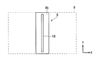
- FIG. 2 is a plan view showing the bottom structure of the mist application head 8.
- FIG. 2 shows the XY coordinate axes.
- a slit-like mist outlet 18 having a longitudinal direction in the Y direction (predetermined direction) is formed on the head bottom surface 8 b of the mist application head 8.
- the virtual plane position of the substrate 9 existing under the head bottom surface 8b of the mist application head 8 is shown.
- the substrate 9 is configured in a rectangular shape having a long side in the X direction and a short side in the Y direction.
- the mist outlet 18 provided in the head bottom surface 8 b is provided in a slit shape with the short side forming direction (Y direction) of the substrate 9 as the longitudinal direction.
- the length) is set to be approximately the same as the short side width of the substrate 9.
- the raw material solution mist 6 rectified in the mist coating head 8 is supplied from the mist ejection port 18 while the substrate 9 is moved along the X direction (short direction of the mist ejection port 18) by the moving stage 10.
- the raw material solution mist 6 can be applied to substantially the entire surface of the substrate 9 to form an ultrathin raw material solution liquid film on the surface of the substrate 9.
- the mist ejection port 18 is formed in a slit shape, the length of the substrate 9 that is the film formation target is shortened by adjusting the formation length in the longitudinal direction (Y direction, predetermined direction) of the mist application head 8. It is not limited to the side width and can be applied to the substrate 9 having a short short side width.
- the formation length of the mist ejection port 18 is substantially equal to the maximum short side width of the substrate 9. Can be matched.
- the moving stage 10 on which the substrate 9 is placed is moved along the X direction under the control of the movement control unit 37 while being 1-5 mm away from the head bottom surface 8b of the mist application head 8.
- An ultrathin raw material solution liquid film can be formed on the surface of the substrate 9 by applying the raw material solution mist 6 on substantially the entire surface of the substrate 9.
- the thickness of the ultrathin raw material solution liquid film can be adjusted by changing the moving speed of the moving stage 10 by the movement control unit 37.
- the movement control unit 37 moves the moving stage 10 along a moving direction (X direction in FIG. 2) that matches the short direction of the mist outlet 18 of the mist application head 8, and moves along the moving direction. 10 moving speeds are variably controlled.
- the mist coating head 8 and the moving stage 10 are provided in the mist coating chamber 11, and the mixed gas of the solvent vapor and the carrier gas of the raw material solution mist 6 volatilized in the mist coating chamber 11 passes through the exhaust gas output line 23. Then, after being processed by an exhaust processing apparatus (not shown), it is released to the atmosphere.
- the valve 23b is a valve provided in the exhaust gas output line 23.
- the firing / drying mechanism 90 has a hot plate 13 provided in the firing / drying chamber 14 as a main component.
- the substrate 9 on which the ultrathin raw material solution liquid film is formed is placed on the hot plate 13 in the baking / drying chamber 14.
- the substrate 9 on which the ultrathin raw material solution liquid film is formed using the hot plate 13 is subjected to baking / drying treatment, whereby the solvent of the ultrathin raw material solution liquid film formed by applying the raw material solution mist 6 is obtained.
- generated by baking / drying process is discharge
- the firing / drying process is performed using the hot plate 13, but the firing / drying mechanism 90 is configured so as to supply hot air into the firing / drying chamber 14 without using the hot plate 13. May be configured.
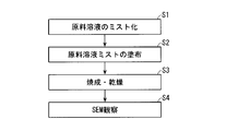
- FIG. 3 is a flowchart showing a film forming procedure of the mist coating film forming method executed using the mist coating film forming apparatus shown in FIG.
- FIG. 4 is an explanatory view schematically showing a state on the surface of the substrate 9 during execution of the mist coating film forming method.
- the processing procedure of the mist coating film forming method will be described with reference to FIGS.
- a raw material solution mist generating mechanism 50 generates a droplet-shaped raw material solution mist 6 by making the raw material solution 5 in the atomization container 4 mist by using the ultrasonic vibrator 1 by the raw material solution mist generating mechanism 50. Execute. Below, the case where a nanofiber dispersion solution is used as the raw material solution 5 will be described.
- a 1 wt% (weight percent) nanofiber dispersion solution is diluted to a viscosity of 1.1 mPa ⁇ s or less to obtain a raw material solution 5.
- the two ultrasonic vibrators 1 (only one ultrasonic vibrator 1 is shown in FIG. 1) that vibrates the raw material solution 5 at 1.6 MHz are driven to mist the raw material solution 5 so that the carrier gas flow rate is 2 L /
- the carrier gas flow rate is 2 L /
- the number of operating transducers in the plurality of ultrasonic transducers 1 and the carrier gas flow rate in the carrier gas supplied from the carrier gas supply unit 16 are controlled under the control of the mist control unit 35 that is an atomization control unit.
- the raw material solution mist 6 can be supplied to the mist coating head 8 in the mist coating mechanism 70 with high accuracy.
- step S ⁇ b> 2 the substrate 9, which is a substrate to be coated, is placed on the moving stage 10 by the mist coating mechanism 70, and the raw material solution mist 6 is supplied from the mist ejection port 18 of the mist coating head 8.
- the raw material solution mist 6 is applied on the surface of the substrate to form an ultrathin raw material solution liquid film 61 (raw material solution liquid film) on the surface of the substrate 9 as shown in FIG. Execute.
- the raw material solution mist 6 rectified in the mist application head 8 is supplied to the surface of the substrate 9 through a mist ejection port 18 formed in a slit shape, whereby the raw material solution mist application process is executed.
- the substrate 9 has a rectangular surface with a long side of 400 (mm) and a short side of 200 (mm).
- the substrate 9 placed (set) on the moving stage 10 exists at a position 1-5 mm below the bottom surface 8b of the head, and the moving stage 10 is controlled by the movement control unit 37 as shown in FIG.
- the movement control unit 37 can variably control the moving speed of the moving stage 10 in the range of 1 to 50 (mm / sec).
- the raw material solution mist 6 In order to apply the raw material solution mist 6 to form the ultrathin raw material solution liquid film 61 on the surface of the substrate 9, the raw material solution mist 6 needs to be well wetted (increase wettability) on the surface of the substrate 9. .
- the raw material solution mist 6 In order for the raw material solution mist 6 to wet well on the surface of the substrate 9, it is necessary to reduce the surface tension of the raw material solution mist 6 and increase the surface tension of the substrate 9.
- the raw material solution 5 is a nanofiber dispersion solution
- methanol is used as the solvent water to reduce the surface tension of the raw material solution mist 6 and remove organic and metal substances that become dirt on the surface of the substrate 9. The surface tension is increased.
- the wettability of the applied raw material solution mist 6 on the surface of the substrate 9 is increased, so that a liquid ultrathin raw material solution liquid film 61 can be formed on the surface of the substrate 9.
- the applied raw material solution mist 6 is well wetted on the surface of the substrate 9, and the ultrathin raw material solution liquid film 61 is obtained. Is forming. Further, by moving only the moving stage 10 on which the substrate 9 is placed while the mist coating head 8 is fixed, the raw material solution mist 6 is coated on the surface of the substrate 9, so that the surface of the substrate 9 can be relatively easily applied. An ultrathin raw material solution liquid film 61 can be formed.
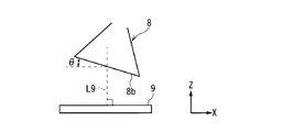
- FIG. 5 is an explanatory view schematically showing the positional relationship of the head bottom surface 8b with respect to the substrate 9.
- the XZ coordinate axes are also shown.
- the raw material solution is obliquely inclined by an angle ⁇ from the perpendicular L9 of the substrate 9 from the mist outlet 18. Mist 6 can be ejected.
- the raw material solution mist 6 due to the carrier gas flow rate from the carrier gas supply unit 16 strikes the surface of the substrate 9.
- the uniformity of the ultrathin raw material solution liquid film 61 is improved by effectively suppressing the disturbance of the liquid film that occurs at the time so that the raw material solution mist 6 can be applied more uniformly on the surface of the substrate 9.
- step S3 the ultrathin raw material solution liquid film 61 formed on the surface of the substrate 9 is baked and dried by the baking / drying mechanism 90, and as shown in FIG.
- Nanofiber thin film 62 (thin film) having a thickness smaller than that of ultrathin raw material solution liquid film 61, which is composed of nanofiber raw materials (predetermined raw materials) such as carbon nanotubes and cellulose nanofibers contained in the dispersion solution on the surface.
- a baking / drying process for forming a film is performed.
- the nanofiber thin film 62 can be formed as a thin film having various functions (barrier property, conductivity, antireflection, hydrophilic property, hydrophobic property).
- the nanofiber thin film 62 can be formed on the surface of the substrate 9 by the mist coating film forming method according to the above steps S1 to S3.
- the nanofiber dispersion solution is used as the raw material solution 5.
- the mist coating film forming method according to steps S1 to S3 described above is performed using the nanoparticle dispersion solution as the raw material solution 5.
- a nanoparticle thin film can be formed on the surface of the substrate 9.
- the mist coating film forming apparatus for executing the mist coating film forming method including steps S1 to S3 shown in FIG.
- the nanofiber dispersion solution is used to apply the raw material solution mist 6 to form the ultrathin raw material solution liquid film 61 on the surface of the substrate 9.
- a thin film nanoparticles having functionality that uses the raw material of the raw material solution 5 (predetermined raw material) as a constituent material on the surface of the substrate 9 by baking and drying the ultrathin raw material solution liquid film 61 by the baking / drying mechanism 90 Thin film or nanofiber thin film).
- the mist coating film forming apparatus of the present embodiment has various functionalities that constitute the raw material (nanoparticle raw material or nanofiber raw material) of the raw material solution 5 contained in the nanoparticle dispersed solution or nanofiber dispersed solution. Can be formed on the surface of the substrate 9 with good uniformity.
- mist coating film forming apparatus of the present embodiment that executes the mist coating film forming method described above does not require a vacuum device, and thus can reduce the initial cost and the running cost. .
- step S4 of FIG. 3 the nanofiber thin film 62 formed on the surface of the substrate 9 was selectively observed with a scanning electron microscope (SEM).
- FIG. 6 is a view showing an observation image of the nanofiber thin film 62 by SEM.
- the nanofiber thin film 62 having a fine fiber structure could be formed by executing the mist coating film forming method by the mist coating film forming apparatus of the present embodiment.
Landscapes
- Life Sciences & Earth Sciences (AREA)
- Engineering & Computer Science (AREA)
- Wood Science & Technology (AREA)
- Application Of Or Painting With Fluid Materials (AREA)
- Spray Control Apparatus (AREA)
- Special Spraying Apparatus (AREA)
Abstract
Description
(ミスト塗布成膜装置(mist coating forming apparatus))
図1は、この発明の実施の形態であるミスト塗布成膜装置の構成を模式的に示す説明図である。同図に示すように、実施の形態1のミスト塗布成膜装置は、原料溶液ミスト化機構50、ミスト塗布機構70、焼成・乾燥機構90を主要構成要素として有している。
原料溶液ミスト化機構50において、超音波振動子1としては、例えば1.5~2.5MHz範囲内の超音波周波数を用いることができる。超音波振動子1上に設けられた水槽2に超音波振動子1で発生した超音波伝播の媒体として水3を導入し、超音波振動子1を駆動することにより、ミスト化容器4に投入した原料溶液5をミスト化(霧化)させて、粒径分布が狭く中心粒径が4μm程度のマイクロメーターサイズの液滴である、原料溶液ミスト6を得る。
ミスト塗布機構70はミスト塗布ヘッド8と成膜対象の基板9を上部に載置して、移動制御部37の制御下で移動可能な移動ステージ10(載置部)を主要構成要素として有している。
焼成・乾燥機構90では焼成・乾燥チャンバー14内に設けられるホットプレート13を主要構成として有している。ミスト塗布機構70によって原料溶液ミスト6の塗布により、表面上に極薄原料溶液液膜が形成された基板9が焼成・乾燥チャンバー14内においてホットプレート13上に載置される。
図3は、図1で示したミスト塗布成膜装置を用いて実行するミスト塗布成膜方法の成膜手順を示すフローチャートである。図4はミスト塗布成膜方法の実行時における基板9の表面上の状態を模式的に示す説明図である。以下、図3及び図4を参照して、ミスト塗布成膜方法の処理手順を説明する。
4 霧化容器
5 原料溶液
6 原料溶液ミスト
8 ミスト塗布ヘッド
8b ヘッド底面
9 基板
10 移動ステージ
11 ミスト塗布チャンバー
13 ホットプレート
14 焼成・乾燥チャンバー
16 キャリアガス供給部
18 ミスト噴出口
21 キャリアガス導入ライン
22 ミスト供給ライン
21b バルブ
35 ミスト制御部
37 移動制御部
50 原料溶液ミスト化機構
70 ミスト塗布機構
90 焼成・乾燥機構
Claims (4)
- 超音波振動子(1)を利用して霧化容器(4)内の原料溶液(5)をミスト化して液滴状の原料溶液ミスト(6)を得る原料溶液ミスト化機構(50)を備え、前記原料溶液は、所定の原料を含むナノ粒子分散溶液あるいはナノファイバー分散溶液であり、
成膜対象となる基板(9)を載置する載置部(10)を有し、前記基板に前記原料溶液ミストを供給し、前記基板の表面上に前記原料溶液ミストを塗布して、前記基板の表面上に原料溶液液膜(61)を形成するミスト塗布機構(70)と、
前記基板の表面上に形成された前記原料溶液液膜を焼成・乾燥して、前記基板の表面上に前記原料溶液液膜に含まれる前記所定の原料を構成材料とした薄膜(62)を成膜する焼成・乾燥機構(90)とをさらに備える、
ミスト塗布成膜装置。 - 請求項1記載のミスト塗布成膜装置であって、
前記原料溶液ミスト化機構は前記原料溶液ミストを前記ミスト塗布機構に向けて搬送するためのキャリアガスを供給するキャリアガス供給部(16)を含む、
ミスト塗布成膜装置。 - 請求項1または請求項2に記載のミスト塗布成膜装置であって、
前記ミスト塗布機構は、ミスト噴出口(18)から前記原料溶液ミストを噴出するミスト塗布ヘッド(8)をさらに有し、前記ミスト噴出口は所定方向を長手方向としたスリット状に形成され、
前記ミスト塗布ヘッドの前記ミスト噴出口の短手方向に合致する移動方向に沿って前記載置部を移動させ、前記移動方向に沿った前記載置部の移動速度を可変制御する移動制御部(37)をさらに有する、
ミスト塗布成膜装置。 - (a) 所定の原料を含む、ナノ粒子分散溶液あるいはナノファイバー分散溶液をミスト化して原料溶液ミスト(6)を得るステップ(S1)と、
(b) 成膜対象となる基板(9)に前記原料溶液ミストを供給し、前記基板の表面上に前記原料溶液ミストを塗布して、前記基板の表面上に原料溶液液膜を形成するステップ(S2)と、
(c) 前記基板の表面上に形成された前記原料溶液液膜を焼成・乾燥して前記基板の表面上に前記所定の原料を含む薄膜を成膜するステップ(S3)とを備える、
ミスト塗布成膜方法。
Priority Applications (7)
| Application Number | Priority Date | Filing Date | Title |
|---|---|---|---|
| US16/315,497 US20190210060A1 (en) | 2016-07-11 | 2016-07-11 | Mist coating forming apparatus and mist coating forming method |
| KR1020197000580A KR102282119B1 (ko) | 2016-07-11 | 2016-07-11 | 미스트 도포 성막 장치 및 미스트 도포 성막 방법 |
| PCT/JP2016/070424 WO2018011854A1 (ja) | 2016-07-11 | 2016-07-11 | ミスト塗布成膜装置及びミスト塗布成膜方法 |
| CN201680087522.7A CN109414718A (zh) | 2016-07-11 | 2016-07-11 | 雾滴涂布成膜装置及雾滴涂布成膜方法 |
| DE112016007052.7T DE112016007052T5 (de) | 2016-07-11 | 2016-07-11 | Sprühbeschichtungsfilmbildungsvorrichtung und Sprühbeschichtungsfilmbildungsverfahren |
| JP2018527056A JPWO2018011854A1 (ja) | 2016-07-11 | 2016-07-11 | ミスト塗布成膜装置及びミスト塗布成膜方法 |
| TW105135689A TWI649444B (zh) | 2016-07-11 | 2016-11-03 | 霧滴塗布成膜裝置及霧滴塗布成膜方法 |
Applications Claiming Priority (1)
| Application Number | Priority Date | Filing Date | Title |
|---|---|---|---|
| PCT/JP2016/070424 WO2018011854A1 (ja) | 2016-07-11 | 2016-07-11 | ミスト塗布成膜装置及びミスト塗布成膜方法 |
Publications (1)
| Publication Number | Publication Date |
|---|---|
| WO2018011854A1 true WO2018011854A1 (ja) | 2018-01-18 |
Family
ID=60953033
Family Applications (1)
| Application Number | Title | Priority Date | Filing Date |
|---|---|---|---|
| PCT/JP2016/070424 Ceased WO2018011854A1 (ja) | 2016-07-11 | 2016-07-11 | ミスト塗布成膜装置及びミスト塗布成膜方法 |
Country Status (7)
| Country | Link |
|---|---|
| US (1) | US20190210060A1 (ja) |
| JP (1) | JPWO2018011854A1 (ja) |
| KR (1) | KR102282119B1 (ja) |
| CN (1) | CN109414718A (ja) |
| DE (1) | DE112016007052T5 (ja) |
| TW (1) | TWI649444B (ja) |
| WO (1) | WO2018011854A1 (ja) |
Cited By (3)
| Publication number | Priority date | Publication date | Assignee | Title |
|---|---|---|---|---|
| JPWO2018220756A1 (ja) * | 2017-05-31 | 2019-11-07 | 東芝三菱電機産業システム株式会社 | ミスト塗布成膜装置の塗布ヘッドおよびそのメンテナンス方法 |
| JP7717436B1 (ja) * | 2024-11-18 | 2025-08-04 | 株式会社Tmeic | 成膜装置 |
| DE112024002881T5 (de) | 2024-08-20 | 2026-05-07 | Tmeic Corporation | Dünnschicht-herstellungsvorrichtung |
Families Citing this family (7)
| Publication number | Priority date | Publication date | Assignee | Title |
|---|---|---|---|---|
| CN110296578B (zh) * | 2019-06-28 | 2021-08-24 | 京东方科技集团股份有限公司 | 一种干燥方法及干燥设备 |
| WO2021019930A1 (ja) * | 2019-07-26 | 2021-02-04 | 富士フイルム株式会社 | スプレー装置およびスプレー塗布方法 |
| PL3885052T3 (pl) * | 2020-03-24 | 2023-03-27 | Akzenta Paneele + Profile Gmbh | Powlekanie krawędzi panelu środkiem powlekającym |
| CN113634428A (zh) * | 2020-07-03 | 2021-11-12 | 徐詹程 | 一种高效冷却的超声波喷头装置 |
| WO2022030187A1 (ja) * | 2020-08-05 | 2022-02-10 | 信越化学工業株式会社 | 製膜用霧化装置、製膜装置及び製膜方法 |
| UA127097C2 (uk) * | 2020-12-29 | 2023-04-12 | Сергій Іванович Єсауленко | Спосіб подрібнення матеріалу в барабанному кульовому млині |
| TWM633563U (zh) * | 2021-03-02 | 2022-11-01 | 日商信越化學工業股份有限公司 | 製膜系統及製膜裝置 |
Citations (8)
| Publication number | Priority date | Publication date | Assignee | Title |
|---|---|---|---|---|
| JP2007517647A (ja) * | 2004-01-05 | 2007-07-05 | ブルー メンブレーンス ゲーエムベーハー | 高周波スプレー装置 |
| JP2008289967A (ja) * | 2007-05-23 | 2008-12-04 | Samco Inc | 薄膜形成方法及び薄膜形成装置 |
| JP2012046772A (ja) * | 2010-08-24 | 2012-03-08 | Sharp Corp | ミストcvd装置及びミスト発生方法 |
| WO2013176222A1 (ja) * | 2012-05-24 | 2013-11-28 | 株式会社ニコン | 基板処理装置、及びデバイス製造方法 |
| JP2014127619A (ja) * | 2012-12-27 | 2014-07-07 | Micronics Japan Co Ltd | 配線形成装置、メンテナンス方法および配線形成方法 |
| JP2015028857A (ja) * | 2013-07-30 | 2015-02-12 | ペクセル・テクノロジーズ株式会社 | 色素増感型光電変換素子およびそれを用いた色素増感型太陽電池の製造方法 |
| JP2015109256A (ja) * | 2013-10-21 | 2015-06-11 | 東芝三菱電機産業システム株式会社 | 活物質製造装置、電池製造システム、フィラー製造装置および樹脂フィルム製造システム |
| JP2016504177A (ja) * | 2012-11-09 | 2016-02-12 | イリノイ トゥール ワークス インコーポレイティド | ナノファイバーを基体に塗布するシステム及び方法 |
Family Cites Families (28)
| Publication number | Priority date | Publication date | Assignee | Title |
|---|---|---|---|---|
| JP4037918B2 (ja) * | 1995-03-20 | 2008-01-23 | フマキラー株式会社 | 薬液噴霧装置 |
| US7045015B2 (en) * | 1998-09-30 | 2006-05-16 | Optomec Design Company | Apparatuses and method for maskless mesoscale material deposition |
| JP2000267396A (ja) * | 1999-03-18 | 2000-09-29 | Canon Inc | 画像形成装置用部材の製造方法 |
| JP2001048588A (ja) * | 1999-06-11 | 2001-02-20 | Symetrix Corp | プラズマディスプレイパネルで使用するための金属酸化物膜を製造する方法 |
| JP2003273111A (ja) * | 2002-03-14 | 2003-09-26 | Seiko Epson Corp | 成膜方法及びその方法を用いて製造したデバイス、並びにデバイスの製造方法 |
| JP2008031541A (ja) | 2006-07-31 | 2008-02-14 | Tokyo Electron Ltd | Cvd成膜方法およびcvd成膜装置 |
| JP2008300212A (ja) * | 2007-05-31 | 2008-12-11 | Toppan Printing Co Ltd | 固体高分子型燃料電池用電極触媒層の製造方法および固体高分子型燃料電池用電極触媒層およびそれを用いた固体高分子型燃料電池 |
| JP2009165951A (ja) * | 2008-01-16 | 2009-07-30 | Sat:Kk | 薄膜形成装置 |
| JP4573902B2 (ja) * | 2008-03-28 | 2010-11-04 | 三菱電機株式会社 | 薄膜形成方法 |
| CA2726143A1 (en) * | 2008-05-29 | 2009-12-10 | Leyden Energy, Inc. | Electrochemical cells with ionic liquid electrolyte |
| JP5581583B2 (ja) * | 2008-11-06 | 2014-09-03 | 凸版印刷株式会社 | 膜電極接合体及び固体高分子形燃料電池 |
| TWI383949B (zh) * | 2008-12-23 | 2013-02-01 | Nat Univ Chung Hsing | Production Method of Transferable Carbon Nanotube Conductive Thin Films |
| TWI441776B (zh) * | 2008-12-23 | 2014-06-21 | Nat Univ Chung Hsing | Fabrication method of electroconductive thin film of carbon nanotubes with excellent flexibility |
| WO2011027425A1 (ja) * | 2009-09-02 | 2011-03-10 | 東芝三菱電機産業システム株式会社 | 金属酸化膜の成膜方法、金属酸化膜および金属酸化膜の成膜装置 |
| TWI414481B (zh) * | 2010-04-13 | 2013-11-11 | Univ Nat Chunghsing | Combined Preparation of Carbon Nanotube Composite Conductive Films with Metal Nanoparticles |
| JP2014504311A (ja) * | 2010-12-03 | 2014-02-20 | テイジン・アラミド・ビー.ブイ. | 高分子量ポリエチレン |
| CN103261135A (zh) * | 2010-12-20 | 2013-08-21 | 花王株式会社 | 浓缩甘油的制造方法 |
| US20150055080A1 (en) * | 2011-10-31 | 2015-02-26 | Hoya Corporation | Eyeglass lens and method of manufacturing the same |
| JP2013230109A (ja) * | 2012-04-27 | 2013-11-14 | Sumitomo Chemical Co Ltd | 超音波霧化装置 |
| US20140272199A1 (en) * | 2013-03-14 | 2014-09-18 | Yi-Jun Lin | Ultrasonic spray coating of conducting and transparent films from combined graphene and conductive nano filaments |
| JP6446768B2 (ja) * | 2013-09-06 | 2019-01-09 | 株式会社村田製作所 | 積層型リチウムイオン固体電池 |
| CN103531663B (zh) * | 2013-10-28 | 2016-01-27 | 哈尔滨理工大学 | CuInS2薄膜太阳能电池吸收层的制备方法 |
| CN110085370B (zh) * | 2013-10-30 | 2021-12-10 | 株式会社尼康 | 薄膜的制造方法 |
| WO2015121915A1 (ja) * | 2014-02-12 | 2015-08-20 | 日東電工株式会社 | 希土類永久磁石及び希土類永久磁石の製造方法 |
| KR101632829B1 (ko) * | 2015-02-17 | 2016-06-22 | 동명대학교산학협력단 | 나노-마이크로 미스트를 이용한 나노입자 적층시스템 |
| JP5958597B2 (ja) * | 2015-04-27 | 2016-08-02 | 凸版印刷株式会社 | 固体高分子形燃料電池用膜電極接合体の製造方法、固体高分子形燃料電池単セルの製造方法、および固体高分子形燃料電池スタックの製造方法 |
| CN105256306B (zh) * | 2015-11-05 | 2018-06-26 | 西安交通大学 | 基于混合粉末的高致密度冷喷涂金属沉积体的制备方法 |
| WO2017098651A1 (ja) * | 2015-12-11 | 2017-06-15 | 東芝三菱電機産業システム株式会社 | ミスト塗布成膜装置及びミスト塗布成膜方法 |
-
2016
- 2016-07-11 CN CN201680087522.7A patent/CN109414718A/zh active Pending
- 2016-07-11 KR KR1020197000580A patent/KR102282119B1/ko active Active
- 2016-07-11 WO PCT/JP2016/070424 patent/WO2018011854A1/ja not_active Ceased
- 2016-07-11 US US16/315,497 patent/US20190210060A1/en not_active Abandoned
- 2016-07-11 DE DE112016007052.7T patent/DE112016007052T5/de active Pending
- 2016-07-11 JP JP2018527056A patent/JPWO2018011854A1/ja active Pending
- 2016-11-03 TW TW105135689A patent/TWI649444B/zh active
Patent Citations (8)
| Publication number | Priority date | Publication date | Assignee | Title |
|---|---|---|---|---|
| JP2007517647A (ja) * | 2004-01-05 | 2007-07-05 | ブルー メンブレーンス ゲーエムベーハー | 高周波スプレー装置 |
| JP2008289967A (ja) * | 2007-05-23 | 2008-12-04 | Samco Inc | 薄膜形成方法及び薄膜形成装置 |
| JP2012046772A (ja) * | 2010-08-24 | 2012-03-08 | Sharp Corp | ミストcvd装置及びミスト発生方法 |
| WO2013176222A1 (ja) * | 2012-05-24 | 2013-11-28 | 株式会社ニコン | 基板処理装置、及びデバイス製造方法 |
| JP2016504177A (ja) * | 2012-11-09 | 2016-02-12 | イリノイ トゥール ワークス インコーポレイティド | ナノファイバーを基体に塗布するシステム及び方法 |
| JP2014127619A (ja) * | 2012-12-27 | 2014-07-07 | Micronics Japan Co Ltd | 配線形成装置、メンテナンス方法および配線形成方法 |
| JP2015028857A (ja) * | 2013-07-30 | 2015-02-12 | ペクセル・テクノロジーズ株式会社 | 色素増感型光電変換素子およびそれを用いた色素増感型太陽電池の製造方法 |
| JP2015109256A (ja) * | 2013-10-21 | 2015-06-11 | 東芝三菱電機産業システム株式会社 | 活物質製造装置、電池製造システム、フィラー製造装置および樹脂フィルム製造システム |
Cited By (3)
| Publication number | Priority date | Publication date | Assignee | Title |
|---|---|---|---|---|
| JPWO2018220756A1 (ja) * | 2017-05-31 | 2019-11-07 | 東芝三菱電機産業システム株式会社 | ミスト塗布成膜装置の塗布ヘッドおよびそのメンテナンス方法 |
| DE112024002881T5 (de) | 2024-08-20 | 2026-05-07 | Tmeic Corporation | Dünnschicht-herstellungsvorrichtung |
| JP7717436B1 (ja) * | 2024-11-18 | 2025-08-04 | 株式会社Tmeic | 成膜装置 |
Also Published As
| Publication number | Publication date |
|---|---|
| US20190210060A1 (en) | 2019-07-11 |
| JPWO2018011854A1 (ja) | 2019-02-14 |
| CN109414718A (zh) | 2019-03-01 |
| DE112016007052T5 (de) | 2019-03-21 |
| TW201802283A (zh) | 2018-01-16 |
| TWI649444B (zh) | 2019-02-01 |
| KR20190016088A (ko) | 2019-02-15 |
| KR102282119B1 (ko) | 2021-07-27 |
Similar Documents
| Publication | Publication Date | Title |
|---|---|---|
| WO2018011854A1 (ja) | ミスト塗布成膜装置及びミスト塗布成膜方法 | |
| JP6490835B2 (ja) | ミスト塗布成膜装置及びミスト塗布成膜方法 | |
| CN103736620B (zh) | 一种超声雾化喷涂薄膜制备方法 | |
| US8567420B2 (en) | Cleaning apparatus for semiconductor wafer | |
| CN102343321B (zh) | 涂覆设备的真空室系统和利用该真空室系统的涂覆方法 | |
| US20040126501A1 (en) | Film-forming method, film-forming apparatus and liquid film drying apparatus | |
| JP2003249492A (ja) | プラズマ放電処理装置、薄膜形成方法及び基材 | |
| JP2012223757A (ja) | 防汚フィルムの常圧蒸着法 | |
| CN110769941A (zh) | 雾涂敷成膜装置的涂敷头及其维护方法 | |
| HK40002123A (en) | Mist-coating film formation apparatus and mist-coating film formation method | |
| TW552163B (en) | Coating device for processing a liquid into fine mist and spraying the fine mist towards a workpiece | |
| KR20090092872A (ko) | 분말 도포 방법 및 장치 | |
| TW201930419A (zh) | 成膜方法 | |
| JP2013211366A (ja) | 静電塗布方法を用いた薄膜形成方法 | |
| TW201934676A (zh) | 成膜方法 | |
| JP2017512125A (ja) | 表面をコーティングするための方法及びその方法を実行するための装置 | |
| JP2006055756A (ja) | レジスト塗布方法 | |
| CN108495719A (zh) | 改进的气溶胶涂布装置和方法 | |
| JP6821280B2 (ja) | セルロースナノファイバーフィルムの製造方法 | |
| JP7434705B2 (ja) | 薄膜形成方法、薄膜形成装置、および機能性薄膜 | |
| JP4866088B2 (ja) | 成膜方法 | |
| WO2025062573A1 (ja) | 基材洗浄装置 | |
| JP2010062500A (ja) | 成膜装置及び成膜方法 | |
| HK40121200A (zh) | 基材清洗装置 | |
| TW202210415A (zh) | 摻鎵氧化鋅粒子、含摻鎵氧化鋅粒子之膜、透明導電膜、電子裝置、及摻鎵氧化鋅粒子之製造方法 |
Legal Events
| Date | Code | Title | Description |
|---|---|---|---|
| ENP | Entry into the national phase |
Ref document number: 2018527056 Country of ref document: JP Kind code of ref document: A |
|
| 121 | Ep: the epo has been informed by wipo that ep was designated in this application |
Ref document number: 16908758 Country of ref document: EP Kind code of ref document: A1 |
|
| ENP | Entry into the national phase |
Ref document number: 20197000580 Country of ref document: KR Kind code of ref document: A |
|
| 122 | Ep: pct application non-entry in european phase |
Ref document number: 16908758 Country of ref document: EP Kind code of ref document: A1 |