WO2018008328A1 - Stator de moteur, procédé de fabrication d'un stator de moteur, et moteur - Google Patents
Stator de moteur, procédé de fabrication d'un stator de moteur, et moteur Download PDFInfo
- Publication number
- WO2018008328A1 WO2018008328A1 PCT/JP2017/021490 JP2017021490W WO2018008328A1 WO 2018008328 A1 WO2018008328 A1 WO 2018008328A1 JP 2017021490 W JP2017021490 W JP 2017021490W WO 2018008328 A1 WO2018008328 A1 WO 2018008328A1
- Authority
- WO
- WIPO (PCT)
- Prior art keywords
- motor
- stator
- tooth
- teeth
- axial direction
- Prior art date
Links
Images


Classifications
-
- H—ELECTRICITY
- H02—GENERATION; CONVERSION OR DISTRIBUTION OF ELECTRIC POWER
- H02K—DYNAMO-ELECTRIC MACHINES
- H02K1/00—Details of the magnetic circuit
- H02K1/06—Details of the magnetic circuit characterised by the shape, form or construction
- H02K1/12—Stationary parts of the magnetic circuit
- H02K1/14—Stator cores with salient poles
- H02K1/146—Stator cores with salient poles consisting of a generally annular yoke with salient poles
- H02K1/148—Sectional cores
-
- H—ELECTRICITY
- H02—GENERATION; CONVERSION OR DISTRIBUTION OF ELECTRIC POWER
- H02K—DYNAMO-ELECTRIC MACHINES
- H02K1/00—Details of the magnetic circuit
- H02K1/06—Details of the magnetic circuit characterised by the shape, form or construction
- H02K1/12—Stationary parts of the magnetic circuit
- H02K1/18—Means for mounting or fastening magnetic stationary parts on to, or to, the stator structures
- H02K1/187—Means for mounting or fastening magnetic stationary parts on to, or to, the stator structures to inner stators
-
- H—ELECTRICITY
- H02—GENERATION; CONVERSION OR DISTRIBUTION OF ELECTRIC POWER
- H02K—DYNAMO-ELECTRIC MACHINES
- H02K15/00—Methods or apparatus specially adapted for manufacturing, assembling, maintaining or repairing of dynamo-electric machines
- H02K15/02—Methods or apparatus specially adapted for manufacturing, assembling, maintaining or repairing of dynamo-electric machines of stator or rotor bodies
- H02K15/024—Methods or apparatus specially adapted for manufacturing, assembling, maintaining or repairing of dynamo-electric machines of stator or rotor bodies with slots
- H02K15/026—Wound cores
-
- H—ELECTRICITY
- H02—GENERATION; CONVERSION OR DISTRIBUTION OF ELECTRIC POWER
- H02K—DYNAMO-ELECTRIC MACHINES
- H02K15/00—Methods or apparatus specially adapted for manufacturing, assembling, maintaining or repairing of dynamo-electric machines
- H02K15/02—Methods or apparatus specially adapted for manufacturing, assembling, maintaining or repairing of dynamo-electric machines of stator or rotor bodies
- H02K15/03—Methods or apparatus specially adapted for manufacturing, assembling, maintaining or repairing of dynamo-electric machines of stator or rotor bodies having permanent magnets
Definitions
- the present invention relates to a motor stator, a motor stator manufacturing method, and a motor.
- a servo motor having a mechanism that automatically operates so as to follow a target value by using the position, orientation, orientation, etc. of an object as a controlled variable.
- the servo motor is used for controlling position, speed, etc. (see, for example, Patent Document 1).
- the movement of the pressing unit is controlled by a servo motor in order to enable a complicated pressing method.
- a servo motor that requires a large force such as this press machine, uses a large motor, and a large torque is required.
- FIG. 7 is a cross-sectional view showing the structure of a conventional motor. As shown in FIG. 7, an armature winding 13 is inserted into a slot 12 formed between a plurality of teeth 11 protruding from the yoke 10 (however, for explanation, the five The armature winding 13 is omitted except for the slot 12).
- FIG. 8 is a detailed view showing the armature winding inserted into the slot.
- the armature winding 13 in the operation of inserting the armature winding 13 into the slot 12, the armature winding 13 is inserted from the opening 14 formed at the tip of the slot. Since the opening 14 is narrow, the operation of inserting the armature winding 13 is very difficult. Further, in order to increase the number of windings, it is necessary to wind the armature winding 13 without a gap, and when winding is manually performed in one slot, several hours may be required.
- the opening 14 is necessary as an entrance when the armature winding 13 is inserted into the slot 12, but if the opening 14 is widened, the space between the teeth 11 is widened. By doing so, the magnetism generated when a current flows through the motor is concentrated on the easily passing teeth 11 and the magnetic fields of the armature winding 13 and the opening 14 become extremely weak. As a result, when the rotor 15 moves, a phenomenon called cogging torque occurs due to a difference in magnetic attractive force. When this cogging torque is generated, there is a problem of causing noise and vibration.
- the opening 14 in the gap between the teeth 11 has a strong influence on the cogging torque.
- winding cannot be performed. It did not come.
- the present invention has been made in view of these points, and provides a stator structure, a stator structure manufacturing method, and a motor that simplify the winding process of the armature winding 13 and reduce cogging torque. With the goal.
- an annular yoke portion provided with a plurality of recesses in an inner peripheral portion and stacked in the axial direction of the motor, and one end of each of the plurality of recesses.
- a plurality of teeth that are radially accommodated, a segment portion having a circular arc at the other end is connected in a ring shape, and the tooth portions stacked in the axial direction are wound around the teeth from the one end side.
- a motor stator is provided.
- the annular yoke part laminated in the axial direction of the motor is provided with a plurality of recesses in the inner peripheral part
- the tooth part is provided with a plurality of teeth having one end accommodated in the plurality of recesses radially, and others.
- the segment portions whose ends are connected in an arc shape are connected in an annular shape and stacked in the axial direction, and the armature winding is wound from one end side of the teeth.
- a step of punching a segment portion having a plurality of teeth radially and having the other end connected in an arc shape from a directional electromagnetic steel sheet, and connecting the segment portions in an annular shape A step of laminating the segment portions connected in an annular shape to form a tooth portion, a step of winding an armature winding around the tooth, and a plurality of recesses in the inner peripheral portion. And a step of fitting into an annular yoke portion laminated in the axial direction.
- a plurality of teeth are provided radially, one end of the segment portion connected in an arc shape is punched from the directional electromagnetic steel sheet, the segment portions are connected in a ring shape, and the ring-connected segment portions are stacked to form a tooth portion. Then, the armature winding is wound from the other end side of the tooth, and the tooth portion is fitted into an annular yoke portion provided with a plurality of concave portions on the inner peripheral portion and laminated in the axial direction.
- the motor in a motor including a rotor and a stator whose teeth are wound with an armature winding, the motor includes a plurality of recesses in an inner peripheral portion and is stacked in the axial direction of the motor. Teeth that are provided with an annular yoke portion and a plurality of teeth whose one ends are housed in the plurality of recesses in a radial manner, and whose other end portions are connected in an arc shape and are annularly connected and stacked in the axial direction There is provided a motor including a stator including a portion and an armature winding wound from the one end side of the tooth.
- the annular yoke part laminated in the axial direction of the motor is provided with a plurality of recesses in the inner peripheral part
- the tooth part is provided with a plurality of teeth having one end accommodated in the plurality of recesses radially, and others.
- the segment portions whose ends are connected in an arc shape are connected in an annular shape and stacked in the axial direction, and the armature winding is wound from one end side of the teeth.
- the annular yoke portion laminated in the axial direction of the motor has a plurality of recesses in the inner peripheral portion, and the tooth portion has a plurality of one ends accommodated in the plurality of recesses. Since the segment portions having the other teeth radially connected to each other in an arc shape are annularly connected and laminated in the axial direction, the armature winding is wound from one end side of the teeth. The wire winding process can be simplified and the cogging torque can be reduced.
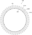
- FIG. 1 is a cross-sectional view showing a configuration of a stator according to the present embodiment.
- the stator 100 includes a yoke part 110, a tooth part 120, and an armature winding 130.
- 48 teeth 121A are taken as an example.
- the yoke part 110 is a non-oriented electrical steel sheet made by punching the outer periphery in a ring shape using a die press and laminated using an adhesive or the like in the motor axial direction.
- a plurality (48 in this embodiment) of recesses 111 are provided on the inner peripheral portion.
- the tooth portion is constituted by a plurality (16 in this embodiment) of segments 121 connected in a ring shape.
- the segment 121 is formed by punching a grain-oriented electrical steel sheet using a die press, and includes a plurality of teeth 121A (three in this embodiment) in a radial pattern.
- One end of the tooth 121A is formed symmetrically with respect to the longitudinal direction of the recess 111 provided in the yoke portion 110 and the tooth 121A, and a part of one end of the tooth 121A is accommodated in the recess 111. Yes.
- the other end of the tooth 121 ⁇ / b> A is connected in a semicircular arc shape to form “E”.
- the segment 121 is connected in an annular shape through the joint 122, and the inner peripheral surface is circular.
- the segments 121 connected in an annular shape are stacked using an adhesive or the like in the motor axial direction.
- a plurality of slots 121B are formed between the respective teeth 121A, and an armature winding 130 is continuously wound in the motor shaft direction in the slots 121B.
- the armature winding 13 In the conventional armature winding work, as shown in FIG. 8, the armature winding 13 must be inserted from the narrow opening 14, and the torque generated in the motor is the same as that of the armature winding 13. Since it is proportional to the number of turns, it was necessary to wind without gaps in order to improve the torque.
- each tooth 121A is provided radially, and the opening 121C of the slot 121B is formed in an open manner. Thereby, the winding work can be easily performed.
- the stator 100 is assembled by inserting the teeth 121A in the motor axial direction in accordance with the recesses 111 provided in the yoke part 110.
- FIG. 2 is a front view showing details of segments constituting the tooth portion.
- the segment 121 is formed by punching the grain-oriented electrical steel sheet 200 using a die press, and includes a plurality of teeth 121A (three in this embodiment) in a radial pattern.
- the grain-oriented electrical steel sheet is a steel sheet having extremely excellent magnetic properties in the rolling direction, and magnetic flux tends to flow in the direction of the arrow 201.
- a magnetic field 123 is generated along the longitudinal direction of the teeth 121A provided in a radial manner.
- the teeth 121A are directed in the rolling direction of the grain-oriented electrical steel sheet along the longitudinal direction of the teeth 121A. Therefore, the magnetic field easily flows and the magnetic field can be increased. Moreover, the magnetic field loss of the magnetic field generated in the tooth portion 120 can be reduced.
- the angle of one tooth 121A is 7.5 degrees. This is because the difference in angle with the tooth 121A compared to the rolling direction of the grain-oriented electrical steel sheet 200 is 7.5 degrees, which is an angle that does not cause a problem in the direction in which the magnetic field passes due to the characteristics.
- the tooth portion 120 can be formed while reducing the above.
- the number of teeth 121A forming the segment 121 can be increased to reduce the number of segments 121 connected.
- the number of teeth 121A is compared with the rolling direction of the grain-oriented electrical steel sheet 200. The difference in angle increases as it reaches both ends of the segment 121. Therefore, the number of teeth 121A included in the segment 121 is desirably 2 to 3.
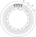
- FIG. 3 is a front view showing a state in which the segment portions are connected to stack the tooth portions.
- FIG. 3A shows a state in which the segments 121 are connected in a ring shape via the joint 122.
- the joints 122 are evenly arranged on the inner peripheral part of the tooth part 120, and one of the joints 122 is arranged at the uppermost end of the inner peripheral circular shape.
- FIG. 3B shows a state in which the segments 121 are connected in a ring shape via the joint 122.
- the joints 122 are evenly arranged on the inner peripheral portion of the tooth portion 120, and are shifted by 7.5 degrees to the left or 15 degrees to the right from the state of FIG.
- the tooth portion 120 is formed by laminating the segments 121 using an adhesive or the like in the motor axial direction, and when laminating, as shown in FIG. It is desirable to laminate so that the seam 122 does not overlap. In this way, the joint 122 is shifted and bonded and laminated, whereby the joint portion is dispersed and a strong structure can be obtained.
- FIG. 4 is a cross-sectional view showing stacked tooth portions. As shown in FIG. 4, the tooth part 120 laminated
- the armature winding 130 is wound around the slot 121B formed in the ridge of the tooth 121A. Since the slot 121B has the opening 121C opened toward the outer peripheral surface, the winding work for winding the armature winding 130 is facilitated.
- the torque generated in the motor is proportional to the number of turns of the armature winding 13, it is desirable to wind the armature winding 130 in the slot 121B without any gap, but the opening 121C is open.
- the armature winding 130 can be easily wound around the slot 121B without gaps even by manual work. Thereby, the torque generated in the motor can be improved.
- the teeth 121A provided in each segment 121 are made of a grain-oriented electrical steel sheet as described above, and are oriented so that the rolling direction is along the longitudinal direction of the teeth 121A. Since the segments 121 are annularly arranged via the joints 122, the rolling direction of the grain-oriented electrical steel sheet is directed in the longitudinal direction of each tooth 121A, that is, radially. Thereby, when a current flows through the motor, a magnetic field is generated along the teeth 121A provided in a radial manner, so that magnetic field loss can be reduced.
- FIG. 5 is a cross-sectional view showing the yoke part. As shown in FIG. 5, a plurality (48 in this embodiment) of concave portions 111 are provided on the inner peripheral portion of the yoke portion 110.
- One end of the tooth 121A is formed symmetrically with respect to the longitudinal direction of the recess 111 provided in the yoke portion 110 and the tooth 121A, and a part of one end of the tooth 121A is accommodated in the recess 111. Yes.
- the tooth portion 120 in which the winding of the armature winding 130 is completed is inserted into the yoke portion 110 so that the tip of the tooth 121A is aligned with the recess 111 provided in the yoke portion 110. Thereby, the tooth part 120 is firmly fixed to the yoke part 110.
- the yoke part 110 is a path of magnetic flux generated in the tooth part 120 when a current flows through the motor, and the direction of the magnetic flux is not constant. Thereby, the yoke part 110 uses a non-oriented electrical steel sheet, and laminates what was created by punching the outer periphery in an annular shape by using a die press in the motor axial direction.
- FIG. 6 is a cross-sectional view showing the stator and the rotor. As shown in FIG. 6, a rotor 300 is provided on the inner peripheral side of the stator 100.
- a plurality of (eight in this embodiment) permanent magnets 320 are fixed to the rotor core 310 at a predetermined interval in the motor axial direction.
- the thus configured rotor 300 faces the inner peripheral surface of the stator 100 through the air gap 400.
- the magnetism generated in the stator 100 is dispersed on the inner peripheral surface of the stator 100 without being concentrated on the teeth 121A because the inner peripheral surface of the stator 100 is closed.
- the difference in magnetic attractive force generated when the rotor 300 moves can be reduced and the cogging torque can be reduced.
Landscapes
- Engineering & Computer Science (AREA)
- Power Engineering (AREA)
- Iron Core Of Rotating Electric Machines (AREA)
- Manufacture Of Motors, Generators (AREA)
- Windings For Motors And Generators (AREA)
Abstract
[Problème] L'invention a pour objet de proposer un stator facilitant un processus de bobinage d'un enroulement d'armature et réduisant un couple de saillance, et un procédé de fabrication du stator. [Solution] Une partie 120 de dents est formée, caractérisée en ce que des parties 121 de segments, dont chacune est munie radialement d'une pluralité de dents 121A et dont une extrémité est prolongée sous la forme d'un arc, sont découpées par poinçonnage à partir d'une tôle 200 en acier électrique à grains orientés, en ce que les parties 121 de segments sont reliées en une forme circulaire, et en ce que les parties 121 de segments reliées sous la forme circulaire sont feuilletées. Un enroulement 130 d'armature est bobiné en partant de l'autre côté extrémité des dents 121A, et la partie 120 de dents est ajustée dans une partie 110 de culasse circulaire, ladite partie 110 de culasse circulaire étant munie d'une pluralité de parties 111 d'évidements sur sa partie circonférentielle intérieure et feuilletée dans la direction axiale du moteur.
Priority Applications (4)
| Application Number | Priority Date | Filing Date | Title |
|---|---|---|---|
| CN201780039458.XA CN109417314A (zh) | 2016-07-08 | 2017-06-09 | 电动机的定子、电动机的定子的制造方法及电动机 |
| EP17823935.6A EP3484016A4 (fr) | 2016-07-08 | 2017-06-09 | Stator de moteur, procédé de fabrication d'un stator de moteur, et moteur |
| JP2018525986A JPWO2018008328A1 (ja) | 2016-07-08 | 2017-06-09 | モータの固定子、モータの固定子の製造方法およびモータ |
| US16/095,095 US11050309B2 (en) | 2016-07-08 | 2017-06-09 | Motor stator, method of manufacturing motor stator, and motor |
Applications Claiming Priority (2)
| Application Number | Priority Date | Filing Date | Title |
|---|---|---|---|
| JP2016135616 | 2016-07-08 | ||
| JP2016-135616 | 2016-07-08 |
Publications (1)
| Publication Number | Publication Date |
|---|---|
| WO2018008328A1 true WO2018008328A1 (fr) | 2018-01-11 |
Family
ID=60912668
Family Applications (1)
| Application Number | Title | Priority Date | Filing Date |
|---|---|---|---|
| PCT/JP2017/021490 WO2018008328A1 (fr) | 2016-07-08 | 2017-06-09 | Stator de moteur, procédé de fabrication d'un stator de moteur, et moteur |
Country Status (6)
| Country | Link |
|---|---|
| US (1) | US11050309B2 (fr) |
| EP (1) | EP3484016A4 (fr) |
| JP (1) | JPWO2018008328A1 (fr) |
| CN (1) | CN109417314A (fr) |
| TW (1) | TWI744349B (fr) |
| WO (1) | WO2018008328A1 (fr) |
Cited By (2)
| Publication number | Priority date | Publication date | Assignee | Title |
|---|---|---|---|---|
| FR3087962A1 (fr) | 2018-10-29 | 2020-05-01 | Circor Industria | Moteur electrique a courant continu sans balai avec un couple de crantage reduit et son procede de fabrication |
| EP3651345A1 (fr) | 2018-11-09 | 2020-05-13 | Circor Industria | Procédé de réduction du couple de crantage produit par des moteurs électriques de type brushless utilises simulatenement |
Families Citing this family (2)
| Publication number | Priority date | Publication date | Assignee | Title |
|---|---|---|---|---|
| JP6742492B1 (ja) * | 2019-11-19 | 2020-08-19 | 田中精密工業株式会社 | 積層鉄心の製造装置及びその製造方法 |
| CN113346640A (zh) * | 2020-03-02 | 2021-09-03 | 尼得科电机(青岛)有限公司 | 内定子铁心、定子、电机和电气产品 |
Citations (5)
| Publication number | Priority date | Publication date | Assignee | Title |
|---|---|---|---|---|
| JP2000245083A (ja) * | 1999-02-24 | 2000-09-08 | Hitachi Ltd | ステータコア及び分割コアブロックの連続製造方法 |
| JP2005143164A (ja) * | 2003-11-04 | 2005-06-02 | Nidec Shibaura Corp | 固定子コア及びその製造方法 |
| JP2009050138A (ja) | 2007-08-21 | 2009-03-05 | Samsung Electronics Co Ltd | ブラシレス直流モータ |
| JP2011125176A (ja) * | 2009-12-14 | 2011-06-23 | Yaskawa Electric Corp | 固定子鉄心およびそれを備えるモータ |
| JP2013510270A (ja) * | 2009-11-06 | 2013-03-21 | アトラス コプコ エアーパワー,ナームローゼ フェンノートシャップ | 磁気軸受のための積層コアおよびこのような積層コアの構成方法 |
Family Cites Families (16)
| Publication number | Priority date | Publication date | Assignee | Title |
|---|---|---|---|---|
| JPH0898440A (ja) * | 1994-09-16 | 1996-04-12 | Asmo Co Ltd | 回転磁界型電動機の固定子 |
| FR2804552B1 (fr) * | 2000-01-28 | 2003-01-03 | Leroy Somer | Procede de fabrication d'un circuit de machine electrique |
| US6747379B2 (en) * | 2002-03-11 | 2004-06-08 | Labrush Edward Clarence | Dynamoelectric machine with reduced vibration |
| JP2004248456A (ja) * | 2003-02-14 | 2004-09-02 | Jianzhun Electric Mach Ind Co Ltd | 単一磁気伝導片からなるモーターステータの磁気伝導片の構造 |
| JP2006050680A (ja) * | 2004-07-08 | 2006-02-16 | Kokusan Denki Co Ltd | 電動機用電機子 |
| CN101243594B (zh) * | 2005-10-24 | 2012-07-04 | 松下电器产业株式会社 | 电容电动机及其制造方法 |
| EP2146417B1 (fr) * | 2007-05-09 | 2016-08-17 | Mitsui High-Tec, Inc. | Noyau de fer feuilleté, et procédé de fabrication de celui-ci |
| JP2010259270A (ja) * | 2009-04-27 | 2010-11-11 | Sanyo Electric Co Ltd | 電動モータ及び電動車輌 |
| MX2012003428A (es) * | 2009-09-21 | 2012-05-08 | Hoeganaes Ab Publ | Dispositivo de estator polifasico. |
| JP5431384B2 (ja) * | 2011-02-14 | 2014-03-05 | 株式会社三井ハイテック | 固定子積層鉄心の製造方法及びそれを用いて製造した固定子積層鉄心 |
| CN102832761B (zh) * | 2012-09-18 | 2014-12-24 | 哈尔滨电机厂有限责任公司 | 定子铁心边段硅钢片叠片粘结成一体的制备方法 |
| CN106233577B (zh) * | 2014-04-16 | 2018-11-02 | 三菱电机株式会社 | 旋转电机的电枢铁芯 |
| JP6400833B2 (ja) * | 2015-03-16 | 2018-10-03 | 黒田精工株式会社 | 積層鉄心の製造方法および積層鉄心の製造装置 |
| DE112017004402T5 (de) * | 2016-09-02 | 2019-05-16 | Nidec Corporation | Stator, statorherstellungsverfahren und motor |
| US20180205301A1 (en) * | 2017-01-17 | 2018-07-19 | Ronald J. Didier | Stacked transflux electric motor |
| KR102607118B1 (ko) * | 2017-10-10 | 2023-11-29 | 제로 이 테크놀로지스 엘엘씨 | 전기 기계의 냉각 및 안정화 시스템 및 방법 |
-
2017
- 2017-06-09 JP JP2018525986A patent/JPWO2018008328A1/ja active Pending
- 2017-06-09 CN CN201780039458.XA patent/CN109417314A/zh active Pending
- 2017-06-09 EP EP17823935.6A patent/EP3484016A4/fr not_active Withdrawn
- 2017-06-09 US US16/095,095 patent/US11050309B2/en active Active
- 2017-06-09 WO PCT/JP2017/021490 patent/WO2018008328A1/fr active Application Filing
- 2017-07-06 TW TW106122639A patent/TWI744349B/zh active
Patent Citations (5)
| Publication number | Priority date | Publication date | Assignee | Title |
|---|---|---|---|---|
| JP2000245083A (ja) * | 1999-02-24 | 2000-09-08 | Hitachi Ltd | ステータコア及び分割コアブロックの連続製造方法 |
| JP2005143164A (ja) * | 2003-11-04 | 2005-06-02 | Nidec Shibaura Corp | 固定子コア及びその製造方法 |
| JP2009050138A (ja) | 2007-08-21 | 2009-03-05 | Samsung Electronics Co Ltd | ブラシレス直流モータ |
| JP2013510270A (ja) * | 2009-11-06 | 2013-03-21 | アトラス コプコ エアーパワー,ナームローゼ フェンノートシャップ | 磁気軸受のための積層コアおよびこのような積層コアの構成方法 |
| JP2011125176A (ja) * | 2009-12-14 | 2011-06-23 | Yaskawa Electric Corp | 固定子鉄心およびそれを備えるモータ |
Non-Patent Citations (1)
| Title |
|---|
| See also references of EP3484016A4 |
Cited By (5)
| Publication number | Priority date | Publication date | Assignee | Title |
|---|---|---|---|---|
| FR3087962A1 (fr) | 2018-10-29 | 2020-05-01 | Circor Industria | Moteur electrique a courant continu sans balai avec un couple de crantage reduit et son procede de fabrication |
| EP3648314A1 (fr) | 2018-10-29 | 2020-05-06 | Circor Industria | Moteur electrique a courant continu sans balai avec un couple de crantage reduit et son procede de realisation |
| US11532975B2 (en) | 2018-10-29 | 2022-12-20 | Circor Industria | Brushless direct current electric motor with reduced cogging torque and production method thereof |
| EP3651345A1 (fr) | 2018-11-09 | 2020-05-13 | Circor Industria | Procédé de réduction du couple de crantage produit par des moteurs électriques de type brushless utilises simulatenement |
| FR3088506A1 (fr) | 2018-11-09 | 2020-05-15 | Circor Industria | Procede de reduction du couple de crantage produit par des moteurs electriques de type brushless utilises simultanement |
Also Published As
| Publication number | Publication date |
|---|---|
| EP3484016A4 (fr) | 2020-03-04 |
| TWI744349B (zh) | 2021-11-01 |
| US11050309B2 (en) | 2021-06-29 |
| US20190068010A1 (en) | 2019-02-28 |
| JPWO2018008328A1 (ja) | 2019-01-24 |
| TW201817130A (zh) | 2018-05-01 |
| CN109417314A (zh) | 2019-03-01 |
| EP3484016A1 (fr) | 2019-05-15 |
Similar Documents
| Publication | Publication Date | Title |
|---|---|---|
| WO2018008328A1 (fr) | Stator de moteur, procédé de fabrication d'un stator de moteur, et moteur | |
| US8890386B2 (en) | Rotor and motor | |
| JP6640621B2 (ja) | 電動機用ロータ、およびブラシレスモータ | |
| WO2012160841A1 (fr) | Machine électrique rotative de type aimant permanent | |
| US11041527B2 (en) | Active radial magnetic bearing with yoke winding | |
| JP5591091B2 (ja) | 積層鉄心の製造方法、積層鉄心、回転電機、及びエレベータ装置 | |
| JP6552713B2 (ja) | 回転電機の固定子及び回転電機 | |
| US10720825B2 (en) | Laminated linear motor stator core | |
| JP2005080474A (ja) | ブラシレスモータ | |
| JPWO2018037529A1 (ja) | 回転電機 | |
| JP2019126102A (ja) | 回転子および回転電機 | |
| WO2020079869A1 (fr) | Moteur linéaire cylindrique | |
| JP4568639B2 (ja) | ステータ | |
| CN107919778B (zh) | 无刷马达及定子的绕线方法 | |
| KR100533012B1 (ko) | 왕복동식 모터의 고정자 구조 | |
| JP2021048751A (ja) | アキシャルギャップモーター | |
| WO2018116415A1 (fr) | Pièce de noyau de stator et machine électrique rotative | |
| JP6022962B2 (ja) | ロータ及びモータ | |
| JP7000750B2 (ja) | 回転電機 | |
| JP6745212B2 (ja) | 回転子およびリラクタンス回転電機 | |
| WO2022107713A1 (fr) | Procédé de fabrication de moteur et de stator | |
| WO2017046950A1 (fr) | Machine électrique tournante | |
| JP5968258B2 (ja) | 電機子鉄心、電機子、回転電機、及び電機子の製造方法 | |
| WO2018230436A1 (fr) | Machine électrique rotative | |
| JP2013240249A (ja) | 回転電機およびその製造方法 |
Legal Events
| Date | Code | Title | Description |
|---|---|---|---|
| WWE | Wipo information: entry into national phase |
Ref document number: 2018525986 Country of ref document: JP |
|
| 121 | Ep: the epo has been informed by wipo that ep was designated in this application |
Ref document number: 17823935 Country of ref document: EP Kind code of ref document: A1 |
|
| NENP | Non-entry into the national phase |
Ref country code: DE |
|
| ENP | Entry into the national phase |
Ref document number: 2017823935 Country of ref document: EP Effective date: 20190208 |