WO2018008328A1 - Motor stator, motor stator manufacturing method, and motor - Google Patents
Motor stator, motor stator manufacturing method, and motor Download PDFInfo
- Publication number
- WO2018008328A1 WO2018008328A1 PCT/JP2017/021490 JP2017021490W WO2018008328A1 WO 2018008328 A1 WO2018008328 A1 WO 2018008328A1 JP 2017021490 W JP2017021490 W JP 2017021490W WO 2018008328 A1 WO2018008328 A1 WO 2018008328A1
- Authority
- WO
- WIPO (PCT)
- Prior art keywords
- motor
- stator
- tooth
- teeth
- axial direction
- Prior art date
Links
Images


Classifications
-
- H—ELECTRICITY
- H02—GENERATION; CONVERSION OR DISTRIBUTION OF ELECTRIC POWER
- H02K—DYNAMO-ELECTRIC MACHINES
- H02K1/00—Details of the magnetic circuit
- H02K1/06—Details of the magnetic circuit characterised by the shape, form or construction
- H02K1/12—Stationary parts of the magnetic circuit
- H02K1/14—Stator cores with salient poles
- H02K1/146—Stator cores with salient poles consisting of a generally annular yoke with salient poles
- H02K1/148—Sectional cores
-
- H—ELECTRICITY
- H02—GENERATION; CONVERSION OR DISTRIBUTION OF ELECTRIC POWER
- H02K—DYNAMO-ELECTRIC MACHINES
- H02K1/00—Details of the magnetic circuit
- H02K1/06—Details of the magnetic circuit characterised by the shape, form or construction
- H02K1/12—Stationary parts of the magnetic circuit
- H02K1/18—Means for mounting or fastening magnetic stationary parts on to, or to, the stator structures
- H02K1/187—Means for mounting or fastening magnetic stationary parts on to, or to, the stator structures to inner stators
-
- H—ELECTRICITY
- H02—GENERATION; CONVERSION OR DISTRIBUTION OF ELECTRIC POWER
- H02K—DYNAMO-ELECTRIC MACHINES
- H02K15/00—Methods or apparatus specially adapted for manufacturing, assembling, maintaining or repairing of dynamo-electric machines
- H02K15/02—Methods or apparatus specially adapted for manufacturing, assembling, maintaining or repairing of dynamo-electric machines of stator or rotor bodies
- H02K15/024—Methods or apparatus specially adapted for manufacturing, assembling, maintaining or repairing of dynamo-electric machines of stator or rotor bodies with slots
- H02K15/026—Wound cores
-
- H—ELECTRICITY
- H02—GENERATION; CONVERSION OR DISTRIBUTION OF ELECTRIC POWER
- H02K—DYNAMO-ELECTRIC MACHINES
- H02K15/00—Methods or apparatus specially adapted for manufacturing, assembling, maintaining or repairing of dynamo-electric machines
- H02K15/02—Methods or apparatus specially adapted for manufacturing, assembling, maintaining or repairing of dynamo-electric machines of stator or rotor bodies
- H02K15/03—Methods or apparatus specially adapted for manufacturing, assembling, maintaining or repairing of dynamo-electric machines of stator or rotor bodies having permanent magnets
Definitions
- the present invention relates to a motor stator, a motor stator manufacturing method, and a motor.
- a servo motor having a mechanism that automatically operates so as to follow a target value by using the position, orientation, orientation, etc. of an object as a controlled variable.
- the servo motor is used for controlling position, speed, etc. (see, for example, Patent Document 1).
- the movement of the pressing unit is controlled by a servo motor in order to enable a complicated pressing method.
- a servo motor that requires a large force such as this press machine, uses a large motor, and a large torque is required.
- FIG. 7 is a cross-sectional view showing the structure of a conventional motor. As shown in FIG. 7, an armature winding 13 is inserted into a slot 12 formed between a plurality of teeth 11 protruding from the yoke 10 (however, for explanation, the five The armature winding 13 is omitted except for the slot 12).
- FIG. 8 is a detailed view showing the armature winding inserted into the slot.
- the armature winding 13 in the operation of inserting the armature winding 13 into the slot 12, the armature winding 13 is inserted from the opening 14 formed at the tip of the slot. Since the opening 14 is narrow, the operation of inserting the armature winding 13 is very difficult. Further, in order to increase the number of windings, it is necessary to wind the armature winding 13 without a gap, and when winding is manually performed in one slot, several hours may be required.
- the opening 14 is necessary as an entrance when the armature winding 13 is inserted into the slot 12, but if the opening 14 is widened, the space between the teeth 11 is widened. By doing so, the magnetism generated when a current flows through the motor is concentrated on the easily passing teeth 11 and the magnetic fields of the armature winding 13 and the opening 14 become extremely weak. As a result, when the rotor 15 moves, a phenomenon called cogging torque occurs due to a difference in magnetic attractive force. When this cogging torque is generated, there is a problem of causing noise and vibration.
- the opening 14 in the gap between the teeth 11 has a strong influence on the cogging torque.
- winding cannot be performed. It did not come.
- the present invention has been made in view of these points, and provides a stator structure, a stator structure manufacturing method, and a motor that simplify the winding process of the armature winding 13 and reduce cogging torque. With the goal.
- an annular yoke portion provided with a plurality of recesses in an inner peripheral portion and stacked in the axial direction of the motor, and one end of each of the plurality of recesses.
- a plurality of teeth that are radially accommodated, a segment portion having a circular arc at the other end is connected in a ring shape, and the tooth portions stacked in the axial direction are wound around the teeth from the one end side.
- a motor stator is provided.
- the annular yoke part laminated in the axial direction of the motor is provided with a plurality of recesses in the inner peripheral part
- the tooth part is provided with a plurality of teeth having one end accommodated in the plurality of recesses radially, and others.
- the segment portions whose ends are connected in an arc shape are connected in an annular shape and stacked in the axial direction, and the armature winding is wound from one end side of the teeth.
- a step of punching a segment portion having a plurality of teeth radially and having the other end connected in an arc shape from a directional electromagnetic steel sheet, and connecting the segment portions in an annular shape A step of laminating the segment portions connected in an annular shape to form a tooth portion, a step of winding an armature winding around the tooth, and a plurality of recesses in the inner peripheral portion. And a step of fitting into an annular yoke portion laminated in the axial direction.
- a plurality of teeth are provided radially, one end of the segment portion connected in an arc shape is punched from the directional electromagnetic steel sheet, the segment portions are connected in a ring shape, and the ring-connected segment portions are stacked to form a tooth portion. Then, the armature winding is wound from the other end side of the tooth, and the tooth portion is fitted into an annular yoke portion provided with a plurality of concave portions on the inner peripheral portion and laminated in the axial direction.
- the motor in a motor including a rotor and a stator whose teeth are wound with an armature winding, the motor includes a plurality of recesses in an inner peripheral portion and is stacked in the axial direction of the motor. Teeth that are provided with an annular yoke portion and a plurality of teeth whose one ends are housed in the plurality of recesses in a radial manner, and whose other end portions are connected in an arc shape and are annularly connected and stacked in the axial direction There is provided a motor including a stator including a portion and an armature winding wound from the one end side of the tooth.
- the annular yoke part laminated in the axial direction of the motor is provided with a plurality of recesses in the inner peripheral part
- the tooth part is provided with a plurality of teeth having one end accommodated in the plurality of recesses radially, and others.
- the segment portions whose ends are connected in an arc shape are connected in an annular shape and stacked in the axial direction, and the armature winding is wound from one end side of the teeth.
- the annular yoke portion laminated in the axial direction of the motor has a plurality of recesses in the inner peripheral portion, and the tooth portion has a plurality of one ends accommodated in the plurality of recesses. Since the segment portions having the other teeth radially connected to each other in an arc shape are annularly connected and laminated in the axial direction, the armature winding is wound from one end side of the teeth. The wire winding process can be simplified and the cogging torque can be reduced.
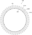
- FIG. 1 is a cross-sectional view showing a configuration of a stator according to the present embodiment.
- the stator 100 includes a yoke part 110, a tooth part 120, and an armature winding 130.
- 48 teeth 121A are taken as an example.
- the yoke part 110 is a non-oriented electrical steel sheet made by punching the outer periphery in a ring shape using a die press and laminated using an adhesive or the like in the motor axial direction.
- a plurality (48 in this embodiment) of recesses 111 are provided on the inner peripheral portion.
- the tooth portion is constituted by a plurality (16 in this embodiment) of segments 121 connected in a ring shape.
- the segment 121 is formed by punching a grain-oriented electrical steel sheet using a die press, and includes a plurality of teeth 121A (three in this embodiment) in a radial pattern.
- One end of the tooth 121A is formed symmetrically with respect to the longitudinal direction of the recess 111 provided in the yoke portion 110 and the tooth 121A, and a part of one end of the tooth 121A is accommodated in the recess 111. Yes.
- the other end of the tooth 121 ⁇ / b> A is connected in a semicircular arc shape to form “E”.
- the segment 121 is connected in an annular shape through the joint 122, and the inner peripheral surface is circular.
- the segments 121 connected in an annular shape are stacked using an adhesive or the like in the motor axial direction.
- a plurality of slots 121B are formed between the respective teeth 121A, and an armature winding 130 is continuously wound in the motor shaft direction in the slots 121B.
- the armature winding 13 In the conventional armature winding work, as shown in FIG. 8, the armature winding 13 must be inserted from the narrow opening 14, and the torque generated in the motor is the same as that of the armature winding 13. Since it is proportional to the number of turns, it was necessary to wind without gaps in order to improve the torque.
- each tooth 121A is provided radially, and the opening 121C of the slot 121B is formed in an open manner. Thereby, the winding work can be easily performed.
- the stator 100 is assembled by inserting the teeth 121A in the motor axial direction in accordance with the recesses 111 provided in the yoke part 110.
- FIG. 2 is a front view showing details of segments constituting the tooth portion.
- the segment 121 is formed by punching the grain-oriented electrical steel sheet 200 using a die press, and includes a plurality of teeth 121A (three in this embodiment) in a radial pattern.
- the grain-oriented electrical steel sheet is a steel sheet having extremely excellent magnetic properties in the rolling direction, and magnetic flux tends to flow in the direction of the arrow 201.
- a magnetic field 123 is generated along the longitudinal direction of the teeth 121A provided in a radial manner.
- the teeth 121A are directed in the rolling direction of the grain-oriented electrical steel sheet along the longitudinal direction of the teeth 121A. Therefore, the magnetic field easily flows and the magnetic field can be increased. Moreover, the magnetic field loss of the magnetic field generated in the tooth portion 120 can be reduced.
- the angle of one tooth 121A is 7.5 degrees. This is because the difference in angle with the tooth 121A compared to the rolling direction of the grain-oriented electrical steel sheet 200 is 7.5 degrees, which is an angle that does not cause a problem in the direction in which the magnetic field passes due to the characteristics.
- the tooth portion 120 can be formed while reducing the above.
- the number of teeth 121A forming the segment 121 can be increased to reduce the number of segments 121 connected.
- the number of teeth 121A is compared with the rolling direction of the grain-oriented electrical steel sheet 200. The difference in angle increases as it reaches both ends of the segment 121. Therefore, the number of teeth 121A included in the segment 121 is desirably 2 to 3.
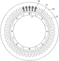
- FIG. 3 is a front view showing a state in which the segment portions are connected to stack the tooth portions.
- FIG. 3A shows a state in which the segments 121 are connected in a ring shape via the joint 122.
- the joints 122 are evenly arranged on the inner peripheral part of the tooth part 120, and one of the joints 122 is arranged at the uppermost end of the inner peripheral circular shape.
- FIG. 3B shows a state in which the segments 121 are connected in a ring shape via the joint 122.
- the joints 122 are evenly arranged on the inner peripheral portion of the tooth portion 120, and are shifted by 7.5 degrees to the left or 15 degrees to the right from the state of FIG.
- the tooth portion 120 is formed by laminating the segments 121 using an adhesive or the like in the motor axial direction, and when laminating, as shown in FIG. It is desirable to laminate so that the seam 122 does not overlap. In this way, the joint 122 is shifted and bonded and laminated, whereby the joint portion is dispersed and a strong structure can be obtained.
- FIG. 4 is a cross-sectional view showing stacked tooth portions. As shown in FIG. 4, the tooth part 120 laminated
- the armature winding 130 is wound around the slot 121B formed in the ridge of the tooth 121A. Since the slot 121B has the opening 121C opened toward the outer peripheral surface, the winding work for winding the armature winding 130 is facilitated.
- the torque generated in the motor is proportional to the number of turns of the armature winding 13, it is desirable to wind the armature winding 130 in the slot 121B without any gap, but the opening 121C is open.
- the armature winding 130 can be easily wound around the slot 121B without gaps even by manual work. Thereby, the torque generated in the motor can be improved.
- the teeth 121A provided in each segment 121 are made of a grain-oriented electrical steel sheet as described above, and are oriented so that the rolling direction is along the longitudinal direction of the teeth 121A. Since the segments 121 are annularly arranged via the joints 122, the rolling direction of the grain-oriented electrical steel sheet is directed in the longitudinal direction of each tooth 121A, that is, radially. Thereby, when a current flows through the motor, a magnetic field is generated along the teeth 121A provided in a radial manner, so that magnetic field loss can be reduced.
- FIG. 5 is a cross-sectional view showing the yoke part. As shown in FIG. 5, a plurality (48 in this embodiment) of concave portions 111 are provided on the inner peripheral portion of the yoke portion 110.
- One end of the tooth 121A is formed symmetrically with respect to the longitudinal direction of the recess 111 provided in the yoke portion 110 and the tooth 121A, and a part of one end of the tooth 121A is accommodated in the recess 111. Yes.
- the tooth portion 120 in which the winding of the armature winding 130 is completed is inserted into the yoke portion 110 so that the tip of the tooth 121A is aligned with the recess 111 provided in the yoke portion 110. Thereby, the tooth part 120 is firmly fixed to the yoke part 110.
- the yoke part 110 is a path of magnetic flux generated in the tooth part 120 when a current flows through the motor, and the direction of the magnetic flux is not constant. Thereby, the yoke part 110 uses a non-oriented electrical steel sheet, and laminates what was created by punching the outer periphery in an annular shape by using a die press in the motor axial direction.
- FIG. 6 is a cross-sectional view showing the stator and the rotor. As shown in FIG. 6, a rotor 300 is provided on the inner peripheral side of the stator 100.
- a plurality of (eight in this embodiment) permanent magnets 320 are fixed to the rotor core 310 at a predetermined interval in the motor axial direction.
- the thus configured rotor 300 faces the inner peripheral surface of the stator 100 through the air gap 400.
- the magnetism generated in the stator 100 is dispersed on the inner peripheral surface of the stator 100 without being concentrated on the teeth 121A because the inner peripheral surface of the stator 100 is closed.
- the difference in magnetic attractive force generated when the rotor 300 moves can be reduced and the cogging torque can be reduced.
Abstract
[Problem] To provide a stator facilitating a process of winding an armature winding and reducing a cogging torque, and a method of manufacturing the stator.
[Solution] A tooth portion 120 is formed in such a way that: segment portions 121 which are each radially provided with a plurality of teeth 121A and one ends of which are extended in an arc shape are punched out from a grain-oriented electrical steel sheet 200, the segment portions 121 are connected in a circular shape, and the segment portions 121 connected in the circular shape are laminated. An armature winding 130 is wound from the other end side of the teeth 121A, and the tooth portion 120 is fitted into a circular yoke portion 110, wherein said circular yoke portion 110 is provided with a plurality of recess portions 111 on the inner circumferential portion and laminated in the axial direction of the motor.
Description
本発明は、モータの固定子、モータの固定子製造方法およびモータに関する。
The present invention relates to a motor stator, a motor stator manufacturing method, and a motor.
従来から、物体の位置、方位、姿勢などを制御量として、目標値に追従するように自動で作動する機構を備えたサーボモータが知られている。またこのサーボモータは、位置や速度等を制御する用途に使われている(たとえば、特許文献1参照)。
Conventionally, a servo motor having a mechanism that automatically operates so as to follow a target value by using the position, orientation, orientation, etc. of an object as a controlled variable is known. The servo motor is used for controlling position, speed, etc. (see, for example, Patent Document 1).
中でも複雑な金型を用いて板材のプレス加工を行うプレス機では、複雑な加圧方法を可能にするために加圧部の動きをサーボモータで制御している。
In particular, in a press machine that presses a plate material using a complicated mold, the movement of the pressing unit is controlled by a servo motor in order to enable a complicated pressing method.
また、このプレス機のような大型な力を必要とするサーボモータは、大型なモータが使用されており、大きなトルクが必要とされている。
Also, a servo motor that requires a large force, such as this press machine, uses a large motor, and a large torque is required.
図7は、従来のモータの構造を示す断面図である。
図7に示すように、継鉄10より突出した複数の歯11の間に形成されたスロット12に電機子巻線13を挿入されている(但し、説明のため図7の上部にある5つのスロット12以外は、電機子巻線13を省略してある)。 FIG. 7 is a cross-sectional view showing the structure of a conventional motor.
As shown in FIG. 7, an armature winding 13 is inserted into aslot 12 formed between a plurality of teeth 11 protruding from the yoke 10 (however, for explanation, the five The armature winding 13 is omitted except for the slot 12).
図7に示すように、継鉄10より突出した複数の歯11の間に形成されたスロット12に電機子巻線13を挿入されている(但し、説明のため図7の上部にある5つのスロット12以外は、電機子巻線13を省略してある)。 FIG. 7 is a cross-sectional view showing the structure of a conventional motor.
As shown in FIG. 7, an armature winding 13 is inserted into a
しかし、大きなトルクを得るためにスロット数を増やした多スロットモータにおいて、電機子巻線をスロットに挿入する作業は非常に多くの時間を必要としてしまう問題があった。
However, in a multi-slot motor in which the number of slots is increased in order to obtain a large torque, there is a problem that the operation of inserting the armature winding into the slot requires a very long time.
図8は、スロットに挿入された電機子巻線を示す詳細図である。
例えば図8に示すように、電機子巻線13をスロット12に挿入する作業は、スロットの先端に形成された開口部14から電機子巻線13を挿入している。開口部14は、狭くなっており電機子巻線13を挿入する作業は非常に困難を要する。また、巻き線数を増やすためには隙間なく電機子巻線13を巻く作業が必要となり、1つのスロットに巻線を手作業で行うと数時間も必要とされる場合もあった。 FIG. 8 is a detailed view showing the armature winding inserted into the slot.
For example, as shown in FIG. 8, in the operation of inserting the armature winding 13 into theslot 12, the armature winding 13 is inserted from the opening 14 formed at the tip of the slot. Since the opening 14 is narrow, the operation of inserting the armature winding 13 is very difficult. Further, in order to increase the number of windings, it is necessary to wind the armature winding 13 without a gap, and when winding is manually performed in one slot, several hours may be required.
例えば図8に示すように、電機子巻線13をスロット12に挿入する作業は、スロットの先端に形成された開口部14から電機子巻線13を挿入している。開口部14は、狭くなっており電機子巻線13を挿入する作業は非常に困難を要する。また、巻き線数を増やすためには隙間なく電機子巻線13を巻く作業が必要となり、1つのスロットに巻線を手作業で行うと数時間も必要とされる場合もあった。 FIG. 8 is a detailed view showing the armature winding inserted into the slot.
For example, as shown in FIG. 8, in the operation of inserting the armature winding 13 into the
また多スロットモータの場合、スロット数が多いので作業量は更に増加し、1つのモータを完成させるのに数日もかかっていた。
Also, in the case of a multi-slot motor, the number of slots is large, so the amount of work increases further, and it takes several days to complete one motor.
この開口部14は、スロット12に電機子巻線13を挿入する際に入り口として必要ではあるが、開口部14を広くすると歯11同士の間が広くなってしまう。そうすることで、モータに電流が流れた際に発生する磁気は通りやすい歯11に集中し、電機子巻線13および開口部14の磁界は極端に弱くなってしまう。これにより、回転子15が動いた際に磁気吸引力に差が生じることによってコギングトルクという現象が発生してしまう。このコギングトルクが発生してしまうと、騒音や振動の原因となってしまう問題があった。
The opening 14 is necessary as an entrance when the armature winding 13 is inserted into the slot 12, but if the opening 14 is widened, the space between the teeth 11 is widened. By doing so, the magnetism generated when a current flows through the motor is concentrated on the easily passing teeth 11 and the magnetic fields of the armature winding 13 and the opening 14 become extremely weak. As a result, when the rotor 15 moves, a phenomenon called cogging torque occurs due to a difference in magnetic attractive force. When this cogging torque is generated, there is a problem of causing noise and vibration.
歯11の隙間の開口部14がコギングトルクへの影響が強く、開口部14を狭くすればするほどコギングトルクは小さくなるが、狭すぎると巻き線を行うことができなくなってしまうので解決には至らなかった。
The opening 14 in the gap between the teeth 11 has a strong influence on the cogging torque. The narrower the opening 14 is, the smaller the cogging torque is. However, if the opening 14 is too narrow, winding cannot be performed. It did not come.
本発明はこのような点に鑑みてなされたものであり、電機子巻線13の巻き線工程を簡易化し、コギングトルクを低減する固定子構造、固定子構造の製造方法およびモータを提供することを目的とする。
The present invention has been made in view of these points, and provides a stator structure, a stator structure manufacturing method, and a motor that simplify the winding process of the armature winding 13 and reduce cogging torque. With the goal.
本発明では上記問題を解決するために、モータの固定子において、内周部に複数の凹部を備え、かつ前記モータの軸方向に積層された環状の継鉄部と、前記複数の凹部に一端が収容される複数の歯を放射状に備え、他端が円弧状に連なったセグメント部が環状に連結され、かつ前記軸方向に積層された歯部と、前記歯に前記一端側から巻線された電機子巻線とを備えることを特徴とするモータの固定子が提供される。
In the present invention, in order to solve the above problem, in a stator of a motor, an annular yoke portion provided with a plurality of recesses in an inner peripheral portion and stacked in the axial direction of the motor, and one end of each of the plurality of recesses. A plurality of teeth that are radially accommodated, a segment portion having a circular arc at the other end is connected in a ring shape, and the tooth portions stacked in the axial direction are wound around the teeth from the one end side. A motor stator is provided.
これにより、モータの軸方向に積層された環状の継鉄部が、内周部に複数の凹部を備え、歯部が、複数の凹部に一端が収容される複数の歯を放射状に備え、他端が円弧状に連なったセグメント部が環状に連結され、かつ軸方向に積層され、電機子巻線が、歯の一端側から巻線される。
Thereby, the annular yoke part laminated in the axial direction of the motor is provided with a plurality of recesses in the inner peripheral part, the tooth part is provided with a plurality of teeth having one end accommodated in the plurality of recesses radially, and others. The segment portions whose ends are connected in an arc shape are connected in an annular shape and stacked in the axial direction, and the armature winding is wound from one end side of the teeth.
また、本発明では、モータの固定子の製造方法において、複数の歯を放射状に備え、他端が円弧状に連なったセグメント部を方向性電磁鋼板から打ち抜く工程と、前記セグメント部を環状に連結する工程と、環状に連結された前記セグメント部を積層して歯部を形成する工程と、電機子巻線を前記歯に巻き線する工程と、前記歯部を、内周部に複数の凹部を備え、軸方向に積層された環状の継鉄部に嵌めこむ工程とを備えることを特徴とするモータの固定子の製造方法が提供される。
Further, according to the present invention, in the method of manufacturing a stator of a motor, a step of punching a segment portion having a plurality of teeth radially and having the other end connected in an arc shape from a directional electromagnetic steel sheet, and connecting the segment portions in an annular shape A step of laminating the segment portions connected in an annular shape to form a tooth portion, a step of winding an armature winding around the tooth, and a plurality of recesses in the inner peripheral portion. And a step of fitting into an annular yoke portion laminated in the axial direction. A method for manufacturing a stator of a motor is provided.
これにより、複数の歯を放射状に備え、一端が円弧状に連なったセグメント部を方向性電磁鋼板から打ち抜き、セグメント部を環状に連結し、環状に連結されたセグメント部を積層して歯部を形成し、電機子巻線を歯の他端側から巻き線し、歯部を、内周部に複数の凹部を備え、軸方向に積層された環状の継鉄部に嵌めこむ。
Accordingly, a plurality of teeth are provided radially, one end of the segment portion connected in an arc shape is punched from the directional electromagnetic steel sheet, the segment portions are connected in a ring shape, and the ring-connected segment portions are stacked to form a tooth portion. Then, the armature winding is wound from the other end side of the tooth, and the tooth portion is fitted into an annular yoke portion provided with a plurality of concave portions on the inner peripheral portion and laminated in the axial direction.
また、本発明では、回転子と、歯が電機子巻線で巻き線された固定子とを備えたモータにおいて、内周部に複数の凹部を備え、かつ前記モータの軸方向に積層された環状の継鉄部と、前記複数の凹部に一端が収容される複数の歯を放射状に備え、他端が円弧状に連なったセグメント部が環状に連結され、かつ前記軸方向に積層された歯部と、前記歯の前記一端側から巻線された電機子巻線とを備える固定子を含むモータが提供される。
Further, in the present invention, in a motor including a rotor and a stator whose teeth are wound with an armature winding, the motor includes a plurality of recesses in an inner peripheral portion and is stacked in the axial direction of the motor. Teeth that are provided with an annular yoke portion and a plurality of teeth whose one ends are housed in the plurality of recesses in a radial manner, and whose other end portions are connected in an arc shape and are annularly connected and stacked in the axial direction There is provided a motor including a stator including a portion and an armature winding wound from the one end side of the tooth.
これにより、モータの軸方向に積層された環状の継鉄部が、内周部に複数の凹部を備え、歯部が、複数の凹部に一端が収容される複数の歯を放射状に備え、他端が円弧状に連なったセグメント部が環状に連結され、かつ軸方向に積層され、電機子巻線が、歯の一端側から巻線される。
Thereby, the annular yoke part laminated in the axial direction of the motor is provided with a plurality of recesses in the inner peripheral part, the tooth part is provided with a plurality of teeth having one end accommodated in the plurality of recesses radially, and others. The segment portions whose ends are connected in an arc shape are connected in an annular shape and stacked in the axial direction, and the armature winding is wound from one end side of the teeth.
本発明のモータの固定子によれば、モータの軸方向に積層された環状の継鉄部が、内周部に複数の凹部を備え、歯部が、複数の凹部に一端が収容される複数の歯を放射状に備え、他端が円弧状に連なったセグメント部が環状に連結され、かつ軸方向に積層され、電機子巻線が、歯の一端側から巻線されるので、電機子巻線の巻き線工程を簡易化ができ、コギングトルクを低減することができる。
According to the stator of the motor of the present invention, the annular yoke portion laminated in the axial direction of the motor has a plurality of recesses in the inner peripheral portion, and the tooth portion has a plurality of one ends accommodated in the plurality of recesses. Since the segment portions having the other teeth radially connected to each other in an arc shape are annularly connected and laminated in the axial direction, the armature winding is wound from one end side of the teeth. The wire winding process can be simplified and the cogging torque can be reduced.
以下、本発明の実施の形態を図面を参照して詳細に説明する。
図1は、本実施の形態に係る固定子の構成を示す断面図である。 Hereinafter, embodiments of the present invention will be described in detail with reference to the drawings.
FIG. 1 is a cross-sectional view showing a configuration of a stator according to the present embodiment.
図1は、本実施の形態に係る固定子の構成を示す断面図である。 Hereinafter, embodiments of the present invention will be described in detail with reference to the drawings.
FIG. 1 is a cross-sectional view showing a configuration of a stator according to the present embodiment.
図1に示すように、固定子100は、継鉄部110、歯部120、および電機子巻線130を備えている。本実施例では、歯121Aを48個としたものを例とする。
As shown in FIG. 1, the stator 100 includes a yoke part 110, a tooth part 120, and an armature winding 130. In the present embodiment, 48 teeth 121A are taken as an example.
継鉄部110は、無方向性電磁鋼板を金型プレスを用いて外周を環状に打ち抜いて作成したものをモータ軸方向に接着剤等を使用して積層したものであり、継鉄部110の内周部には複数(本実施例では48個)の凹部111を備えている。
The yoke part 110 is a non-oriented electrical steel sheet made by punching the outer periphery in a ring shape using a die press and laminated using an adhesive or the like in the motor axial direction. A plurality (48 in this embodiment) of recesses 111 are provided on the inner peripheral portion.
歯部は複数の(本実施例では16個)セグメント121が環状に連結されて構成されている。セグメント121は方向性電磁鋼板を金型プレスを用いて打ち抜いて形成されたものであり、放射状に複数の歯121A(本実施例では3個)を備えている。継鉄部110に設けられた凹部111と歯121Aの長手方向に対して、歯121Aの一端は対称に形成されており、歯121Aの一端の一部が凹部111に収容される形状をしている。歯121Aの他端は、半円弧状を成して連結され「E」の形状をしている。
The tooth portion is constituted by a plurality (16 in this embodiment) of segments 121 connected in a ring shape. The segment 121 is formed by punching a grain-oriented electrical steel sheet using a die press, and includes a plurality of teeth 121A (three in this embodiment) in a radial pattern. One end of the tooth 121A is formed symmetrically with respect to the longitudinal direction of the recess 111 provided in the yoke portion 110 and the tooth 121A, and a part of one end of the tooth 121A is accommodated in the recess 111. Yes. The other end of the tooth 121 </ b> A is connected in a semicircular arc shape to form “E”.
セグメント121は、継ぎ目122を介して環状に連結され、内周面は円状になる。また、環状に連結されたセグメント121は、モータ軸方向に接着剤等を使用して積層される。
The segment 121 is connected in an annular shape through the joint 122, and the inner peripheral surface is circular. In addition, the segments 121 connected in an annular shape are stacked using an adhesive or the like in the motor axial direction.
歯部120には、各歯121Aの間にスロット121Bが複数形成されており、スロット121Bには電機子巻線130が連続してモータ軸方向に巻線される。
In the tooth portion 120, a plurality of slots 121B are formed between the respective teeth 121A, and an armature winding 130 is continuously wound in the motor shaft direction in the slots 121B.
従来の電機子巻線の巻線作業は、図8のように、狭い開口部14から電機子巻線13を挿入しなくてはならず、またモータに発生するトルクは電機子巻線13の巻き数に比例するため、トルクを向上させるには隙間なく巻線する必要があった。
In the conventional armature winding work, as shown in FIG. 8, the armature winding 13 must be inserted from the narrow opening 14, and the torque generated in the motor is the same as that of the armature winding 13. Since it is proportional to the number of turns, it was necessary to wind without gaps in order to improve the torque.
本実施例では、各歯121Aが放射状に備えられており、スロット121Bの開口部121Cは開放的に形成されている。これにより、巻線作業が簡単に行えるようになる。
In this embodiment, each tooth 121A is provided radially, and the opening 121C of the slot 121B is formed in an open manner. Thereby, the winding work can be easily performed.
巻線作業を終えると、継鉄部110に設けられた凹部111に合わせて、歯121Aをモータ軸方向に挿入し、固定子100が組み立てられている。
When the winding work is finished, the stator 100 is assembled by inserting the teeth 121A in the motor axial direction in accordance with the recesses 111 provided in the yoke part 110.
図2は、歯部を構成するセグメントの詳細を示す正面図である。
図2に示すように、セグメント121は方向性電磁鋼板200を金型プレスを用いて打ち抜いて形成されたものであり、放射状に複数の歯121A(本実施例では3個)を備えている。 FIG. 2 is a front view showing details of segments constituting the tooth portion.
As shown in FIG. 2, thesegment 121 is formed by punching the grain-oriented electrical steel sheet 200 using a die press, and includes a plurality of teeth 121A (three in this embodiment) in a radial pattern.
図2に示すように、セグメント121は方向性電磁鋼板200を金型プレスを用いて打ち抜いて形成されたものであり、放射状に複数の歯121A(本実施例では3個)を備えている。 FIG. 2 is a front view showing details of segments constituting the tooth portion.
As shown in FIG. 2, the
方向性電磁鋼板は、圧延方向にきわめて優れた磁気特性を有する鋼板であり、矢印201方向に磁束が流れやすくなっている。
The grain-oriented electrical steel sheet is a steel sheet having extremely excellent magnetic properties in the rolling direction, and magnetic flux tends to flow in the direction of the arrow 201.
モータに電流が流れると、放射状に設けられた歯121Aの長手方向に沿って磁界123が発生するが、歯121Aは、歯121Aの長手方向に沿って方向性電磁鋼板の圧延方向が向けられているので、磁界が流れやすくなり、磁界が大きく取れるようになる。また、歯部120に発生する磁界の磁界損失を低減することができる。
When a current flows through the motor, a magnetic field 123 is generated along the longitudinal direction of the teeth 121A provided in a radial manner. The teeth 121A are directed in the rolling direction of the grain-oriented electrical steel sheet along the longitudinal direction of the teeth 121A. Therefore, the magnetic field easily flows and the magnetic field can be increased. Moreover, the magnetic field loss of the magnetic field generated in the tooth portion 120 can be reduced.
また、1つ1つ歯121A分割した形状で圧延方向に合わせて打ち抜き、放射状に組み立てる工程と比べると、本実施例では、あらかじめ3個の歯121Aを連ねたセグメント121を環状に組み立てるだけなので環状に歯部120を配置する作業工程を大幅に短縮することができる。
Also, compared to the process of punching in the rolling direction in the shape of each tooth 121A divided and assembling radially, in this embodiment, since the segment 121 having three teeth 121A connected in advance is annularly assembled, it is annular. The work process of arranging the tooth portion 120 can be greatly shortened.
また、本実施例では全体で48個の歯121Aであるので、1つの歯121Aの角度は7.5度である。これは方向性電磁鋼板200の圧延方向と比べて歯121Aとの角度の差は7.5度となり、特性上磁界の通る向きにおいて問題にならない角度なので、歯部120に発生する磁界の磁界損失を低減させたまま歯部120を形成することができる。
Further, in the present embodiment, since there are a total of 48 teeth 121A, the angle of one tooth 121A is 7.5 degrees. This is because the difference in angle with the tooth 121A compared to the rolling direction of the grain-oriented electrical steel sheet 200 is 7.5 degrees, which is an angle that does not cause a problem in the direction in which the magnetic field passes due to the characteristics. The tooth portion 120 can be formed while reducing the above.
また、トルクを向上させるためにスロット数を増やすと、歯121Aの数の角度は小さくなり、圧延方向に近づくことになる。このため、トルクを向上させるスロット数の多いモータは、より方向性電磁鋼板の特性を活かすことが出来る。
Also, when the number of slots is increased in order to improve the torque, the angle of the number of teeth 121A becomes smaller and approaches the rolling direction. For this reason, a motor with a large number of slots for improving the torque can make better use of the characteristics of the grain-oriented electrical steel sheet.
また、セグメント121を形成する歯121Aの数を増やして、セグメント121の連結する数を減らすこともできるが、歯121Aの数を増やすと方向性電磁鋼板200の圧延方向と比べて歯121Aとの角度の差がセグメント121の両端部になるほど増加してしまう。そのためセグメント121が備える歯121Aの数量は2~3個であることが望ましい。
In addition, the number of teeth 121A forming the segment 121 can be increased to reduce the number of segments 121 connected. However, when the number of teeth 121A is increased, the number of teeth 121A is compared with the rolling direction of the grain-oriented electrical steel sheet 200. The difference in angle increases as it reaches both ends of the segment 121. Therefore, the number of teeth 121A included in the segment 121 is desirably 2 to 3.
図3は、セグメント部を連結して歯部を積層する様子を示す正面図である。
図3(a)は、継ぎ目122を介してセグメント121を環状に連結した様子を表している。継ぎ目122は歯部120の内周部に均等に配置され、そのうち1つの継ぎ目122が内周円状の最上端にくるように配置されている。 FIG. 3 is a front view showing a state in which the segment portions are connected to stack the tooth portions.
FIG. 3A shows a state in which thesegments 121 are connected in a ring shape via the joint 122. The joints 122 are evenly arranged on the inner peripheral part of the tooth part 120, and one of the joints 122 is arranged at the uppermost end of the inner peripheral circular shape.
図3(a)は、継ぎ目122を介してセグメント121を環状に連結した様子を表している。継ぎ目122は歯部120の内周部に均等に配置され、そのうち1つの継ぎ目122が内周円状の最上端にくるように配置されている。 FIG. 3 is a front view showing a state in which the segment portions are connected to stack the tooth portions.
FIG. 3A shows a state in which the
図3は、(b)は、継ぎ目122を介してセグメント121を環状に連結した様子を表している。継ぎ目122は歯部120の内周部に均等に配置され、図3(a)の状態から左に7.5度、または右に15度ずらして配置してある。
FIG. 3B shows a state in which the segments 121 are connected in a ring shape via the joint 122. The joints 122 are evenly arranged on the inner peripheral portion of the tooth portion 120, and are shifted by 7.5 degrees to the left or 15 degrees to the right from the state of FIG.
歯部120は、セグメント121をモータ軸方向に接着剤等を使用して積層していくが、積層していく際に、図3(a)の上に図3(b)を重ねるように、継ぎ目122が重ならないように積層していくのが望ましい。このように継ぎ目122をずらして接着して積層することにより、接合部が分散され強固な構造をとることができる。
The tooth portion 120 is formed by laminating the segments 121 using an adhesive or the like in the motor axial direction, and when laminating, as shown in FIG. It is desirable to laminate so that the seam 122 does not overlap. In this way, the joint 122 is shifted and bonded and laminated, whereby the joint portion is dispersed and a strong structure can be obtained.
上記のように、積層を繰り返していく度に継ぎ目122が重ならないように積層していき、全体的に継ぎ目122の位置が偏らないように配置および積層をしていくことが望ましい。
As described above, it is desirable to stack the layers so that the joints 122 do not overlap each time the stacking is repeated, and to arrange and stack the joints 122 so that the positions of the joints 122 are not biased as a whole.
図4は、積層された歯部を示す断面図である。
図4に示すように、モータ軸方向に積層された歯部120は複数のセグメント121からなり、放射状に歯121Aを備えている。 FIG. 4 is a cross-sectional view showing stacked tooth portions.
As shown in FIG. 4, thetooth part 120 laminated | stacked on the motor axial direction consists of the some segment 121, and is equipped with the tooth | gear 121A radially.
図4に示すように、モータ軸方向に積層された歯部120は複数のセグメント121からなり、放射状に歯121Aを備えている。 FIG. 4 is a cross-sectional view showing stacked tooth portions.
As shown in FIG. 4, the
歯部120の積層が完了すると、歯121Aのハイダに形成されたスロット121Bに電機子巻線130を巻線していく。スロット121Bは、外周面方向に向かって開口部121Cが開放されているので、電機子巻線130を巻線する巻線作業がしやすくなっている。
When the stacking of the tooth portions 120 is completed, the armature winding 130 is wound around the slot 121B formed in the ridge of the tooth 121A. Since the slot 121B has the opening 121C opened toward the outer peripheral surface, the winding work for winding the armature winding 130 is facilitated.
またモータに発生するトルクは電機子巻線13の巻き数に比例するため、スロット121Bに隙間なく電機子巻線130を巻線していくことが望ましいが、開口部121Cが開放されているので、手作業でも容易に隙間なく電機子巻線130をスロット121Bに巻線していくことができる。これにより、モータに発生するトルクを向上することができる。
Further, since the torque generated in the motor is proportional to the number of turns of the armature winding 13, it is desirable to wind the armature winding 130 in the slot 121B without any gap, but the opening 121C is open. The armature winding 130 can be easily wound around the slot 121B without gaps even by manual work. Thereby, the torque generated in the motor can be improved.
また、各セグメント121に備えられた歯121Aは、前述したとおり方向性電磁鋼板で作成されており、歯121Aの長手方向に圧延方向が沿うように向けられている。このセグメント121を環状に継ぎ目122を介して配置されているので、各歯121Aの長手方向、つまり放射状に方向性電磁鋼板の圧延方向が向けられている。これにより、モータに電流が流れると、放射状に設けられた歯121Aに沿って磁界が発生するので、磁界損失を低減することができる。
Further, the teeth 121A provided in each segment 121 are made of a grain-oriented electrical steel sheet as described above, and are oriented so that the rolling direction is along the longitudinal direction of the teeth 121A. Since the segments 121 are annularly arranged via the joints 122, the rolling direction of the grain-oriented electrical steel sheet is directed in the longitudinal direction of each tooth 121A, that is, radially. Thereby, when a current flows through the motor, a magnetic field is generated along the teeth 121A provided in a radial manner, so that magnetic field loss can be reduced.
図5は、継鉄部を示す断面図である。
図5に示すように、継鉄部110の内周部には複数(本実施例では48個)の凹部111を備えている。 FIG. 5 is a cross-sectional view showing the yoke part.
As shown in FIG. 5, a plurality (48 in this embodiment) ofconcave portions 111 are provided on the inner peripheral portion of the yoke portion 110.
図5に示すように、継鉄部110の内周部には複数(本実施例では48個)の凹部111を備えている。 FIG. 5 is a cross-sectional view showing the yoke part.
As shown in FIG. 5, a plurality (48 in this embodiment) of
継鉄部110に設けられた凹部111と歯121Aの長手方向に対して、歯121Aの一端は対称に形成されており、歯121Aの一端の一部が凹部111に収容される形状をしている。継鉄部110に設けられた凹部111に歯121Aの先端を合わせるようにして、電機子巻線130の巻線が完了した歯部120を継鉄部110に挿入する。これにより、歯部120が継鉄部110にしっかりと固定される。
One end of the tooth 121A is formed symmetrically with respect to the longitudinal direction of the recess 111 provided in the yoke portion 110 and the tooth 121A, and a part of one end of the tooth 121A is accommodated in the recess 111. Yes. The tooth portion 120 in which the winding of the armature winding 130 is completed is inserted into the yoke portion 110 so that the tip of the tooth 121A is aligned with the recess 111 provided in the yoke portion 110. Thereby, the tooth part 120 is firmly fixed to the yoke part 110.
継鉄部110は、モータに電流が流れた際に歯部120に発生する磁束の通路であり、磁束の方向は一定ではない。これにより、継鉄部110は無方向性電磁鋼板を使用し、金型プレスを用いて外周を環状に打ち抜いて作成したものをモータ軸方向に接着剤等を使用して積層する。
The yoke part 110 is a path of magnetic flux generated in the tooth part 120 when a current flows through the motor, and the direction of the magnetic flux is not constant. Thereby, the yoke part 110 uses a non-oriented electrical steel sheet, and laminates what was created by punching the outer periphery in an annular shape by using a die press in the motor axial direction.
図6は、固定子および回転子の示す断面図である。
図6に示すように、固定子100の内周側に回転子300が備えられている。 FIG. 6 is a cross-sectional view showing the stator and the rotor.
As shown in FIG. 6, arotor 300 is provided on the inner peripheral side of the stator 100.
図6に示すように、固定子100の内周側に回転子300が備えられている。 FIG. 6 is a cross-sectional view showing the stator and the rotor.
As shown in FIG. 6, a
回転子300は、回転子鉄心310に複数の(本実施例では8個)の永久磁石320が所定間隔でモータ軸方向に向かって固定されている。
In the rotor 300, a plurality of (eight in this embodiment) permanent magnets 320 are fixed to the rotor core 310 at a predetermined interval in the motor axial direction.
このように構成された回転子300は、固定子100の内周面とエアギャップ400を介して対向している。
The thus configured rotor 300 faces the inner peripheral surface of the stator 100 through the air gap 400.
電機子巻線130に電流が流れると固定子100に発生する磁気は、固定子100の内周面は閉塞されているので、歯121Aに集中せずに固定子100の内周面に分散される。これにより、回転子300が動いた際に生じる磁気吸引力の差が低減されコギングトルクを減少させることが出来る。
When the current flows through the armature winding 130, the magnetism generated in the stator 100 is dispersed on the inner peripheral surface of the stator 100 without being concentrated on the teeth 121A because the inner peripheral surface of the stator 100 is closed. The As a result, the difference in magnetic attractive force generated when the rotor 300 moves can be reduced and the cogging torque can be reduced.
10 継鉄
11 歯
12 スロット
13 電機子巻線
14 開口部
15 回転子
100 固定子
110 継鉄部
111 凹部
120 歯部
121 セグメント
121A 歯
121B スロット
121C 開口部
122 継ぎ目
123 磁界
130 電機子巻線
200 方向性電磁鋼板
201 矢印
300 回転子
310 回転子鉄心
320 永久磁石
400 エアギャップ 10yoke 11 tooth 12 slot 13 armature winding 14 opening 15 rotor 100 stator 110 yoke portion 111 recess 120 tooth 121 segment 121A tooth 121B slot 121C opening 122 joint 123 magnetic field 130 armature winding 200 direction Magnetic steel sheet 201 Arrow 300 Rotor 310 Rotor core 320 Permanent magnet 400 Air gap
11 歯
12 スロット
13 電機子巻線
14 開口部
15 回転子
100 固定子
110 継鉄部
111 凹部
120 歯部
121 セグメント
121A 歯
121B スロット
121C 開口部
122 継ぎ目
123 磁界
130 電機子巻線
200 方向性電磁鋼板
201 矢印
300 回転子
310 回転子鉄心
320 永久磁石
400 エアギャップ 10
Claims (8)
- モータの固定子において、
内周部に複数の凹部を備え、かつ前記モータの軸方向に積層された環状の継鉄部と、
前記複数の凹部に一端が収容される複数の歯を放射状に備え、他端が円弧状に連なったセグメント部が環状に連結され、かつ前記軸方向に積層された歯部と、
前記歯の前記一端側から巻線された電機子巻線と、
を備えることを特徴とするモータの固定子。 In the motor stator,
An annular yoke portion provided with a plurality of recesses in the inner peripheral portion and stacked in the axial direction of the motor;
A plurality of teeth, one end of which is accommodated in the plurality of recesses, is provided radially, the other end is connected in an arc shape, and the tooth portions are connected in a ring shape and stacked in the axial direction;
An armature winding wound from the one end side of the tooth;
The stator of the motor characterized by comprising. - 環状に連結された前記セグメントは、
積層時において前記軸方向に隣接する環状の前記セグメントに生じる継ぎ目が一致しないようにずらして配置され積層されることを特徴とする請求項1記載のモータの固定子。 The segments connected in a ring are
The stator of a motor according to claim 1, wherein at the time of stacking, the stators are stacked so as to be shifted so that seams generated in the annular segments adjacent in the axial direction do not coincide with each other. - 前記継ぎ目は、
前記モータの前記軸方向に投影した際に、前記セグメント上で偏りなく均等に配置され積層されることを特徴とする請求項2記載のモータの固定子。 The seam is
3. The motor stator according to claim 2, wherein the motor stator is evenly arranged and laminated on the segments when projected in the axial direction of the motor. - 前記歯部の内周面は、
円状に連なり、前記歯と前記歯との間が閉塞されていることを特徴とする請求項1記載のモータの固定子。 The inner peripheral surface of the tooth part is
The stator of the motor according to claim 1, wherein the stator is continuous in a circular shape and is closed between the teeth. - 前記セグメント部は、
前記歯の長手方向に磁束の流れやすい圧延方向を向けた方向性電磁鋼板からなることを特徴とする請求項1記載のモータの固定子。 The segment part is
2. The motor stator according to claim 1, wherein the stator is made of a directional electromagnetic steel sheet having a rolling direction in which the magnetic flux easily flows in the longitudinal direction of the teeth. - 前記継鉄部は、
全方向に向けて平均的に優れた磁気特性を有する無方向性電磁鋼板からなることを特徴とする請求項1記載のモータの固定子。 The yoke part is
2. The motor stator according to claim 1, wherein the stator is made of a non-oriented electrical steel sheet having on average excellent magnetic properties in all directions. - モータの固定子の製造方法において、
複数の歯を放射状に備え、一端が円弧状に連なったセグメント部を方向性電磁鋼板から打ち抜く工程と、
前記セグメント部を環状に連結する工程と、
環状に連結された前記セグメント部を積層して歯部を形成する工程と、
電機子巻線を前記歯の他端側から巻き線する工程と、
前記歯部を、内周部に複数の凹部を備え、軸方向に積層された環状の継鉄部に嵌めこむ工程と、
を備えることを特徴とするモータの固定子の製造方法。 In the manufacturing method of the stator of the motor,
A step of radially providing a plurality of teeth and punching out a segment portion having one end connected in an arc shape from a grain-oriented electrical steel sheet;
Connecting the segment portions in an annular shape;
A step of laminating the segment portions connected in an annular shape to form a tooth portion;
Winding the armature winding from the other end of the tooth;
A step of fitting the tooth part into an annular yoke part provided with a plurality of recesses in the inner peripheral part and laminated in the axial direction;
The manufacturing method of the stator of the motor characterized by the above-mentioned. - 回転子と、
歯が電機子巻線で巻き線された固定子と、
を備えたモータにおいて、
内周部に複数の凹部を備え、かつ前記モータの軸方向に積層された環状の継鉄部と、
前記複数の凹部に一端が収容される複数の歯を放射状に備え、他端が円弧状に連なったセグメント部が環状に連結され、かつ前記軸方向に積層された歯部と、
前記歯の前記一端側から巻線された電機子巻線と、
を備えるモータの固定子を含むモータ。 A rotor,
A stator with teeth wound with armature windings;
In motors with
An annular yoke portion provided with a plurality of recesses in the inner peripheral portion and stacked in the axial direction of the motor;
A plurality of teeth, one end of which is accommodated in the plurality of recesses, is provided radially, the other end is connected in an arc shape, and the tooth portions are connected in a ring shape and stacked in the axial direction;
An armature winding wound from the one end side of the tooth;
A motor including a motor stator.
Priority Applications (4)
| Application Number | Priority Date | Filing Date | Title |
|---|---|---|---|
| US16/095,095 US11050309B2 (en) | 2016-07-08 | 2017-06-09 | Motor stator, method of manufacturing motor stator, and motor |
| EP17823935.6A EP3484016A4 (en) | 2016-07-08 | 2017-06-09 | Motor stator, motor stator manufacturing method, and motor |
| JP2018525986A JPWO2018008328A1 (en) | 2016-07-08 | 2017-06-09 | Motor stator, motor stator manufacturing method, and motor |
| CN201780039458.XA CN109417314A (en) | 2016-07-08 | 2017-06-09 | The manufacturing method and motor of the stator of motor, the stator of motor |
Applications Claiming Priority (2)
| Application Number | Priority Date | Filing Date | Title |
|---|---|---|---|
| JP2016-135616 | 2016-07-08 | ||
| JP2016135616 | 2016-07-08 |
Publications (1)
| Publication Number | Publication Date |
|---|---|
| WO2018008328A1 true WO2018008328A1 (en) | 2018-01-11 |
Family
ID=60912668
Family Applications (1)
| Application Number | Title | Priority Date | Filing Date |
|---|---|---|---|
| PCT/JP2017/021490 WO2018008328A1 (en) | 2016-07-08 | 2017-06-09 | Motor stator, motor stator manufacturing method, and motor |
Country Status (6)
| Country | Link |
|---|---|
| US (1) | US11050309B2 (en) |
| EP (1) | EP3484016A4 (en) |
| JP (1) | JPWO2018008328A1 (en) |
| CN (1) | CN109417314A (en) |
| TW (1) | TWI744349B (en) |
| WO (1) | WO2018008328A1 (en) |
Cited By (2)
| Publication number | Priority date | Publication date | Assignee | Title |
|---|---|---|---|---|
| FR3087962A1 (en) | 2018-10-29 | 2020-05-01 | Circor Industria | BRUSHLESS DIRECT CURRENT ELECTRIC MOTOR WITH REDUCED TORQUE AND MANUFACTURING METHOD THEREOF |
| EP3651345A1 (en) | 2018-11-09 | 2020-05-13 | Circor Industria | Method for reducing the detent torque produced by brushless type electric motors used simultaneously |
Families Citing this family (2)
| Publication number | Priority date | Publication date | Assignee | Title |
|---|---|---|---|---|
| JP6742492B1 (en) * | 2019-11-19 | 2020-08-19 | 田中精密工業株式会社 | Manufacturing apparatus and method for manufacturing laminated core |
| CN113346640A (en) * | 2020-03-02 | 2021-09-03 | 尼得科电机(青岛)有限公司 | Inner stator iron core, stator, motor and electric product |
Citations (5)
| Publication number | Priority date | Publication date | Assignee | Title |
|---|---|---|---|---|
| JP2000245083A (en) * | 1999-02-24 | 2000-09-08 | Hitachi Ltd | Stator core and continuous manufacture of divided core block |
| JP2005143164A (en) * | 2003-11-04 | 2005-06-02 | Nidec Shibaura Corp | Stator core and its manufacturing method |
| JP2009050138A (en) | 2007-08-21 | 2009-03-05 | Samsung Electronics Co Ltd | Brushless dc motor |
| JP2011125176A (en) * | 2009-12-14 | 2011-06-23 | Yaskawa Electric Corp | Stator core and motor with the same |
| JP2013510270A (en) * | 2009-11-06 | 2013-03-21 | アトラス コプコ エアーパワー,ナームローゼ フェンノートシャップ | Laminated core for magnetic bearing and method for constructing such laminated core |
Family Cites Families (16)
| Publication number | Priority date | Publication date | Assignee | Title |
|---|---|---|---|---|
| JPH0898440A (en) * | 1994-09-16 | 1996-04-12 | Asmo Co Ltd | Stator for rotating field type motor |
| FR2804552B1 (en) * | 2000-01-28 | 2003-01-03 | Leroy Somer | METHOD FOR MANUFACTURING AN ELECTRIC MACHINE CIRCUIT |
| US6747379B2 (en) * | 2002-03-11 | 2004-06-08 | Labrush Edward Clarence | Dynamoelectric machine with reduced vibration |
| JP2004248456A (en) * | 2003-02-14 | 2004-09-02 | Jianzhun Electric Mach Ind Co Ltd | Structure of magnetic conduction piece of motor stator composed of single magnetic conduction piece |
| JP2006050680A (en) * | 2004-07-08 | 2006-02-16 | Kokusan Denki Co Ltd | Armature for motor |
| CN101243594B (en) * | 2005-10-24 | 2012-07-04 | 松下电器产业株式会社 | Capacitor motor and process for producing the same |
| JP5129810B2 (en) * | 2007-05-09 | 2013-01-30 | 株式会社三井ハイテック | Laminated iron core and method for manufacturing the same |
| JP2010259270A (en) * | 2009-04-27 | 2010-11-11 | Sanyo Electric Co Ltd | Electric motor and electric vehicle |
| IN2012DN03313A (en) * | 2009-09-21 | 2015-10-23 | Hoganas Ab Publ | |
| JP5431384B2 (en) * | 2011-02-14 | 2014-03-05 | 株式会社三井ハイテック | Stator laminated core manufacturing method and stator laminated core manufactured using the same |
| CN102832761B (en) | 2012-09-18 | 2014-12-24 | 哈尔滨电机厂有限责任公司 | Preparation method for bonding laminated pieces of silicon steel piece at edge section of iron core of stator into whole |
| US10128700B2 (en) * | 2014-04-16 | 2018-11-13 | Mitsubishi Electric Corporation | Rotary electric machine armature core |
| CN107408872B (en) * | 2015-03-16 | 2019-07-26 | 黑田精工株式会社 | The manufacturing method of laminated iron core and the manufacturing device of laminated iron core |
| CN109565194B (en) * | 2016-09-02 | 2021-03-09 | 日本电产株式会社 | Stator, method for manufacturing stator, and motor |
| US20180205301A1 (en) * | 2017-01-17 | 2018-07-19 | Ronald J. Didier | Stacked transflux electric motor |
| EP3695487A1 (en) * | 2017-10-10 | 2020-08-19 | Zero E Technologies LLC | Electric machine cooling and stabilization systems and methods |
-
2017
- 2017-06-09 CN CN201780039458.XA patent/CN109417314A/en active Pending
- 2017-06-09 US US16/095,095 patent/US11050309B2/en active Active
- 2017-06-09 JP JP2018525986A patent/JPWO2018008328A1/en active Pending
- 2017-06-09 WO PCT/JP2017/021490 patent/WO2018008328A1/en active Application Filing
- 2017-06-09 EP EP17823935.6A patent/EP3484016A4/en not_active Withdrawn
- 2017-07-06 TW TW106122639A patent/TWI744349B/en active
Patent Citations (5)
| Publication number | Priority date | Publication date | Assignee | Title |
|---|---|---|---|---|
| JP2000245083A (en) * | 1999-02-24 | 2000-09-08 | Hitachi Ltd | Stator core and continuous manufacture of divided core block |
| JP2005143164A (en) * | 2003-11-04 | 2005-06-02 | Nidec Shibaura Corp | Stator core and its manufacturing method |
| JP2009050138A (en) | 2007-08-21 | 2009-03-05 | Samsung Electronics Co Ltd | Brushless dc motor |
| JP2013510270A (en) * | 2009-11-06 | 2013-03-21 | アトラス コプコ エアーパワー,ナームローゼ フェンノートシャップ | Laminated core for magnetic bearing and method for constructing such laminated core |
| JP2011125176A (en) * | 2009-12-14 | 2011-06-23 | Yaskawa Electric Corp | Stator core and motor with the same |
Non-Patent Citations (1)
| Title |
|---|
| See also references of EP3484016A4 |
Cited By (5)
| Publication number | Priority date | Publication date | Assignee | Title |
|---|---|---|---|---|
| FR3087962A1 (en) | 2018-10-29 | 2020-05-01 | Circor Industria | BRUSHLESS DIRECT CURRENT ELECTRIC MOTOR WITH REDUCED TORQUE AND MANUFACTURING METHOD THEREOF |
| EP3648314A1 (en) | 2018-10-29 | 2020-05-06 | Circor Industria | Brushless direct current electric motor with reduced detent torque and method for manufacturing same |
| US11532975B2 (en) | 2018-10-29 | 2022-12-20 | Circor Industria | Brushless direct current electric motor with reduced cogging torque and production method thereof |
| EP3651345A1 (en) | 2018-11-09 | 2020-05-13 | Circor Industria | Method for reducing the detent torque produced by brushless type electric motors used simultaneously |
| FR3088506A1 (en) | 2018-11-09 | 2020-05-15 | Circor Industria | METHOD FOR REDUCING THE SPRING TORQUE PRODUCED BY BRUSHLESS TYPE ELECTRIC MOTORS USED SIMULTANEOUSLY |
Also Published As
| Publication number | Publication date |
|---|---|
| TW201817130A (en) | 2018-05-01 |
| US11050309B2 (en) | 2021-06-29 |
| TWI744349B (en) | 2021-11-01 |
| CN109417314A (en) | 2019-03-01 |
| EP3484016A4 (en) | 2020-03-04 |
| EP3484016A1 (en) | 2019-05-15 |
| US20190068010A1 (en) | 2019-02-28 |
| JPWO2018008328A1 (en) | 2019-01-24 |
Similar Documents
| Publication | Publication Date | Title |
|---|---|---|
| WO2018008328A1 (en) | Motor stator, motor stator manufacturing method, and motor | |
| US8890386B2 (en) | Rotor and motor | |
| JP6640621B2 (en) | Motor rotor and brushless motor | |
| WO2012160841A1 (en) | Permanent magnet-type rotating electric machine | |
| US11041527B2 (en) | Active radial magnetic bearing with yoke winding | |
| JP5591091B2 (en) | Manufacturing method of laminated iron core, laminated iron core, rotating electric machine, and elevator apparatus | |
| JP6552713B2 (en) | Stator of rotating electric machine and rotating electric machine | |
| US10720825B2 (en) | Laminated linear motor stator core | |
| JP2005080474A (en) | Brushless motor | |
| JPWO2018037529A1 (en) | Rotating electric machine | |
| JP2019126102A (en) | Rotor and rotary electric machine | |
| WO2020079869A1 (en) | Cylindrical linear motor | |
| JP4568639B2 (en) | Stator | |
| CN107919778B (en) | Brushless motor and winding method of stator | |
| KR100533012B1 (en) | Stater structure for reciprocating motor | |
| WO2018116415A1 (en) | Stator core piece and rotating electric machine | |
| JP6022962B2 (en) | Rotor and motor | |
| JP7000750B2 (en) | Rotating machine | |
| JP2021048751A (en) | Axial gap motor | |
| JP6745212B2 (en) | Rotor and reluctance rotating electric machine | |
| WO2022107713A1 (en) | Motor and stator manufacturing method | |
| WO2017046950A1 (en) | Rotary electric machine | |
| JP5968258B2 (en) | Armature core, armature, rotating electric machine, and manufacturing method of armature | |
| WO2018230436A1 (en) | Rotating electric machine | |
| JP2013240249A (en) | Rotary electric machine and method for manufacturing the same |
Legal Events
| Date | Code | Title | Description |
|---|---|---|---|
| WWE | Wipo information: entry into national phase |
Ref document number: 2018525986 Country of ref document: JP |
|
| 121 | Ep: the epo has been informed by wipo that ep was designated in this application |
Ref document number: 17823935 Country of ref document: EP Kind code of ref document: A1 |
|
| NENP | Non-entry into the national phase |
Ref country code: DE |
|
| ENP | Entry into the national phase |
Ref document number: 2017823935 Country of ref document: EP Effective date: 20190208 |