JP5129810B2 - Laminated iron core and method for manufacturing the same - Google Patents
Laminated iron core and method for manufacturing the same Download PDFInfo
- Publication number
- JP5129810B2 JP5129810B2 JP2009514059A JP2009514059A JP5129810B2 JP 5129810 B2 JP5129810 B2 JP 5129810B2 JP 2009514059 A JP2009514059 A JP 2009514059A JP 2009514059 A JP2009514059 A JP 2009514059A JP 5129810 B2 JP5129810 B2 JP 5129810B2
- Authority
- JP
- Japan
- Prior art keywords
- core
- laminated
- connecting portion
- segment
- pieces
- Prior art date
- Legal status (The legal status is an assumption and is not a legal conclusion. Google has not performed a legal analysis and makes no representation as to the accuracy of the status listed.)
- Expired - Fee Related
Links
- 238000000034 method Methods 0.000 title claims description 48
- XEEYBQQBJWHFJM-UHFFFAOYSA-N Iron Chemical group [Fe] XEEYBQQBJWHFJM-UHFFFAOYSA-N 0.000 title claims description 42
- 238000004519 manufacturing process Methods 0.000 title claims description 37
- 238000003860 storage Methods 0.000 claims description 53
- 238000005452 bending Methods 0.000 claims description 20
- 230000002093 peripheral effect Effects 0.000 claims description 15
- 239000002184 metal Substances 0.000 claims description 7
- 229910052751 metal Inorganic materials 0.000 claims description 7
- 230000036961 partial effect Effects 0.000 claims description 6
- 238000004804 winding Methods 0.000 claims description 6
- 238000003825 pressing Methods 0.000 claims description 5
- 239000011162 core material Substances 0.000 description 186
- 238000003780 insertion Methods 0.000 description 5
- 230000037431 insertion Effects 0.000 description 5
- 230000007423 decrease Effects 0.000 description 4
- 238000004080 punching Methods 0.000 description 4
- 229910000831 Steel Inorganic materials 0.000 description 3
- 230000004308 accommodation Effects 0.000 description 3
- 238000010030 laminating Methods 0.000 description 3
- 238000003475 lamination Methods 0.000 description 3
- 230000004048 modification Effects 0.000 description 3
- 238000012986 modification Methods 0.000 description 3
- 230000002829 reductive effect Effects 0.000 description 3
- 239000010959 steel Substances 0.000 description 3
- 239000000463 material Substances 0.000 description 2
- 230000008961 swelling Effects 0.000 description 2
- 230000002411 adverse Effects 0.000 description 1
- 230000015572 biosynthetic process Effects 0.000 description 1
- 230000008878 coupling Effects 0.000 description 1
- 238000010168 coupling process Methods 0.000 description 1
- 238000005859 coupling reaction Methods 0.000 description 1
- 238000005520 cutting process Methods 0.000 description 1
- 230000003247 decreasing effect Effects 0.000 description 1
- 238000006073 displacement reaction Methods 0.000 description 1
- 230000000694 effects Effects 0.000 description 1
- 230000000670 limiting effect Effects 0.000 description 1
- 238000003908 quality control method Methods 0.000 description 1
- 238000003466 welding Methods 0.000 description 1
Images


Classifications
-
- H—ELECTRICITY
- H02—GENERATION; CONVERSION OR DISTRIBUTION OF ELECTRIC POWER
- H02K—DYNAMO-ELECTRIC MACHINES
- H02K1/00—Details of the magnetic circuit
- H02K1/06—Details of the magnetic circuit characterised by the shape, form or construction
- H02K1/12—Stationary parts of the magnetic circuit
- H02K1/14—Stator cores with salient poles
- H02K1/146—Stator cores with salient poles consisting of a generally annular yoke with salient poles
- H02K1/148—Sectional cores
-
- H—ELECTRICITY
- H02—GENERATION; CONVERSION OR DISTRIBUTION OF ELECTRIC POWER
- H02K—DYNAMO-ELECTRIC MACHINES
- H02K15/00—Methods or apparatus specially adapted for manufacturing, assembling, maintaining or repairing of dynamo-electric machines
- H02K15/02—Methods or apparatus specially adapted for manufacturing, assembling, maintaining or repairing of dynamo-electric machines of stator or rotor bodies
-
- Y—GENERAL TAGGING OF NEW TECHNOLOGICAL DEVELOPMENTS; GENERAL TAGGING OF CROSS-SECTIONAL TECHNOLOGIES SPANNING OVER SEVERAL SECTIONS OF THE IPC; TECHNICAL SUBJECTS COVERED BY FORMER USPC CROSS-REFERENCE ART COLLECTIONS [XRACs] AND DIGESTS
- Y10—TECHNICAL SUBJECTS COVERED BY FORMER USPC
- Y10T—TECHNICAL SUBJECTS COVERED BY FORMER US CLASSIFICATION
- Y10T29/00—Metal working
- Y10T29/49—Method of mechanical manufacture
- Y10T29/49002—Electrical device making
- Y10T29/49009—Dynamoelectric machine
Landscapes
- Engineering & Computer Science (AREA)
- Power Engineering (AREA)
- Manufacturing & Machinery (AREA)
- Manufacture Of Motors, Generators (AREA)
- Iron Core Of Rotating Electric Machines (AREA)
Description
本発明は、連結部を介して連結された複数のセグメント鉄心片を、螺旋状に巻回して積層形成した積層鉄心及びその製造方法に関する。なお、ここで、積層鉄心とはモータや発電機の固定子及び回転子をいう。 The present invention relates to a laminated core in which a plurality of segment core pieces connected via a connecting portion are spirally wound and formed, and a method for manufacturing the same. Here, the laminated core means a stator and a rotor of a motor or a generator.
従来、積層鉄心の製造に使用する鉄心材料の歩留向上方法として、鉄心材料から鉄心片を打抜く際、環状とせずに、帯状に連なる複数のセグメント鉄心片を帯状磁性鋼板から打抜き形成し、これを巻回しながら積層して積層鉄心を製造するいわゆる巻き形鉄心が知られている。
具体的には、例えば、特許文献1〜3に記載のように、所定数のスロットを有する円弧状のセグメント鉄心片同士を、連結部を介して相互に結合した状態で、鉄心材料から金型で打抜く。そして、外周側に形成された連結部を折り曲げ、隣り合うセグメント鉄心片の側端部を合わせながら、連続した複数のセグメント鉄心片を螺旋状に巻回して積層する。
しかし、前記特許文献1〜3に記載の技術においては、複数のセグメント鉄心片を環状に配置するため連結部を折り曲げる際に、連結部の肉厚方向に膨出部が発生し、この膨出部が積層したセグメント鉄心片間に隙間を生じさせ、製造した積層鉄心の厚みにばらつきを生じさせていた。この隙間は、モータの効率低下又は振動を招く原因となり、モータの品質に悪影響を及ぼすという問題があった。Conventionally, as a method for improving the yield of iron core materials used in the manufacture of laminated iron cores, when punching iron core pieces from iron core materials, a plurality of segment iron core pieces connected in a strip shape are punched from a belt-shaped magnetic steel sheet, without forming an annular shape, A so-called wound iron core is known in which a laminated iron core is manufactured by laminating this while being wound.
Specifically, for example, as described in Patent Documents 1 to 3, arc-shaped segment core pieces having a predetermined number of slots are joined to each other via a connecting portion, and the mold is made from the core material. Punch with. And the connection part formed in the outer peripheral side is bend | folded, the continuous several segment core piece is wound spirally and laminated | stacked, aligning the side edge part of an adjacent segment core piece.
However, in the techniques described in Patent Documents 1 to 3, when the connecting portion is bent in order to arrange the plurality of segment core pieces in an annular shape, a bulging portion is generated in the thickness direction of the connecting portion. A gap was generated between the segmented iron core pieces in which the portions were laminated, resulting in variations in the thickness of the produced laminated iron core. This gap causes a decrease in efficiency or vibration of the motor, and has a problem of adversely affecting the quality of the motor.
そこで、発生する膨出部による隙間を無くす方法として、以下に示す図6(A)、(B)、図7(A)、(B)の方法がある。
図6(A)に示す方法は、複数のセグメント鉄心片80を打抜く打抜き工程で、連結部81の圧縮応力がかかる部分に対して予めコイニング加工(押圧加工)を行うことにより、折り曲げ時の連結部81の厚さ(肉厚)方向の膨出量を減少させ、例え厚みが増加した場合でも、連結部81の厚みをコイニング加工前の厚み以下にする方法である。
また、図6(B)に示す方法は、セグメント鉄心片85の連結部86の折り曲げ後に、連結部86の厚みが増加した部分を、連結部86の厚み方向から押し潰す方法である。Therefore, as a method of eliminating the gap due to the generated bulging portion, there are methods shown in FIGS. 6A, 6B, 7A, and 7B described below.
The method shown in FIG. 6 (A) is a punching process in which a plurality of
Further, the method shown in FIG. 6B is a method of crushing, from the thickness direction of the connecting
そして、図7(A)に示す方法は、セグメント鉄心片90の連結部91の折り曲げ後に、連結部91の厚みが増加した部分を、上下に積層されたセグメント鉄心片90に形成した貫通孔92内に逃がす方法である。
更に、図7(B)に示す方法は、セグメント鉄心片95の連結部96の折り曲げ後に、連結部96の厚みが増加した部分を、上下に積層されたセグメント鉄心片95に形成した切欠き97により逃がす方法である。The method shown in FIG. 7A is a through-
Further, in the method shown in FIG. 7B, after the connecting
しかしながら、前記それぞれの方法においては、以下の問題があった。
図6(A)に示すように、連結部81に対してコイニング加工を行うことで、折り曲げ時の連結部81の厚みをコイニング加工前の厚み以下にすることはできるが、コイニング加工によりその部分が加工硬化し、折り曲げ時に連結部81が切断され易くなる。また、連結部81の半径方向の幅が1mm以下と細いため、この部分に対してコイニング加工を行うと、連結部81の強度が低下し、セグメント鉄心片80の搬送中に連結部81が切断されてしまう恐れがある。However, each of the above methods has the following problems.
As shown in FIG. 6 (A), by performing coining on the connecting
このように、セグメント鉄心片80の搬送時又は連結部81の折り曲げ時に、連結部81が切断されると、複数のセグメント鉄心片80を巻回する際に、切断された部分同士が干渉し合う。このため、隣り合うセグメント鉄心片80を隙間無く揃えることができず、発生した隙間によって積層鉄心の寸法精度が低下したり、また複数のセグメント鉄心片80の巻回の作業性が悪くなる問題がある。また、切断された部分が積層鉄心の外側円内より外方へ突出する場合には、これを除去する工程を新たに設ける必要もある。
更に、コイニング加工の深さには限界があり、連結部81の厚み増加量が大きい材料を使用する場合には、この方法を適用することができない。Thus, when the connecting
Furthermore, there is a limit to the depth of the coining process, and this method cannot be applied when using a material with a large thickness increase of the connecting
また、図6(B)に示すように、折り曲げ後の連結部86の厚みが増加した部分を潰すと、連結部86の円周方向に材料が伸び、隣り合うセグメント鉄心片85間に隙間が発生し、巻回したセグメント鉄心片85のピッチ寸法がばらついて、積層鉄心の寸法精度が低下する問題がある。
更に、図7(A)に示すように、上下に隣接する層のセグメント鉄心片90に、連結部91の膨出部が嵌入する貫通孔(逃し孔)92を形成したり、また図7(B)に示すように、上下に隣接する層のセグメント鉄心片95に、連結部96の膨出部が嵌入する切欠き97を形成した場合には、積層鉄心を使用するモータの種類によっては、その性能が低下する恐れがある。Further, as shown in FIG. 6B, when the portion where the thickness of the connecting
Further, as shown in FIG. 7A, through-holes (relief holes) 92 into which the bulging portions of the connecting
本発明はかかる事情に鑑みてなされたもので、連結部の厚み方向の膨出の影響を受けることなく、高効率で高品質の製品を製造可能な積層鉄心及びその製造方法を提供することを目的とする。 The present invention has been made in view of such circumstances, and provides a laminated core capable of manufacturing a high-quality and high-quality product without being affected by the bulging of the connecting portion in the thickness direction, and a method for manufacturing the same. Objective.
前記目的に沿う第1の発明に係る積層鉄心は、外周領域に形成された連結部で相互に結合された隣り合うセグメント鉄心片の前記連結部を折り曲げて、前記セグメント鉄心片の半径方向内側又は外側の端部を同一円周上に配置するように合わせながら、該連続した複数の前記セグメント鉄心片を螺旋状に巻回して積層し、隣接する層に設けられた前記連結部同士を周方向にずらしながら配置した積層鉄心において、
前記連結部の半径方向外側には該連結部の折り曲げ時に半径方向外側に形成される半径方向膨出部を該積層鉄心の外側円内に収める凹部切欠きを有し、
前記連結部の半径方向内側には、該連結部の折り曲げ位置を形成する内側切欠きを設け、前記連結部を除く前記セグメント鉄心片の半径方向外側には、前記連結部の折り曲げ時にその(即ち、連結部の)厚み方向に形成される厚み方向膨出部を入れ込む収納凹部を表裏に設けている。The laminated core according to the first invention that meets the above-described object is formed by bending the connecting portions of adjacent segment core pieces joined together by connecting portions formed in an outer peripheral region, and While aligning the outer ends so as to be arranged on the same circumference, the plurality of continuous segment core pieces are spirally wound and laminated, and the connecting portions provided in adjacent layers are circumferentially arranged. In the laminated iron core arranged while shifting
On the outer side in the radial direction of the connecting part, there is a recess notch that accommodates a radially bulging part formed on the outer side in the radial direction when the connecting part is bent in an outer circle of the laminated core,
An inner notch for forming a bending position of the connecting portion is provided on the radially inner side of the connecting portion, and the segment core piece excluding the connecting portion is provided on the radially outer side of the segment core piece when the connecting portion is bent (that is, Storage recesses are provided on the front and back sides for inserting a bulge portion in the thickness direction formed in the thickness direction (of the connecting portion).
ここで、外周領域とは、セグメント鉄心片の半径方向最外部から半径方向内側の部分に対応する領域をいい、例えば、セグメント鉄心片の半径方向の外周を基準として、セグメント鉄心片の半径方向最大幅の1/30〜1/5に対応する領域(即ち、半径幅領域)をいう(第2の発明に係る積層鉄心の製造方法においても同じ)。なお、外周領域を、セグメント鉄心片(固定子積層鉄心の場合は磁極片部を除く)の半径方向の外周を基準として、セグメント鉄心片の半径方向最大幅の1/30〜1/2に対応する半径幅領域とすることもできる(以下の実施例においても同じ)。 Here, the outer peripheral region refers to a region corresponding to the radially inner portion of the segment core piece from the radially outermost portion. An area corresponding to a substantial 1/30 to 1/5 (that is, a radial width area) is said (the same applies to the method for manufacturing a laminated core according to the second invention). The outer peripheral area corresponds to 1/30 to 1/2 of the maximum radial width of the segment core piece, based on the outer periphery in the radial direction of the segment core piece (excluding the magnetic pole piece in the case of the stator laminated core). It is also possible to use a radial width region (the same applies to the following embodiments).
第1の発明に係る積層鉄心において、前記収納凹部は、円錐、円錐台、四角錐、四角錐台、部分球、及び平面視して多角形のいずれか1であるのが好ましい。
第1の発明に係る積層鉄心において、前記収納凹部の深さは、前記セグメント鉄心片の厚み(通常、0.15〜0.5mmが一般的)の0.15〜0.3倍であるのがよい。
第1の発明に係る積層鉄心において、前記収納凹部の中央位置には貫通孔が設けられているのが更に好ましい。In the laminated iron core according to the first aspect of the present invention, the storage recess is preferably any one of a cone, a truncated cone, a quadrangular pyramid, a quadrangular pyramid, a partial sphere, and a polygon in plan view.
In the laminated core according to the first invention, the depth of the storage recess is 0.15 to 0.3 times the thickness of the segment core piece (usually 0.15 to 0.5 mm is common). Is good.
In the laminated iron core according to the first invention, it is more preferable that a through hole is provided at a central position of the housing recess.
第1の発明に係る積層鉄心において、前記貫通孔の体積は、該貫通孔を除く前記表裏の前記収納凹部の合計体積の0.7〜1.5倍の範囲にあるのが好ましい。
第1の発明に係る積層鉄心において、隣り合う前記セグメント鉄心片の側部には、凹部とこれに嵌合する凸部からなる係合部が形成されているのが好ましい。
ここで、前記凹部と凸部は半円形状又は中心角が50度以上で180度未満の扇形形状(円弧形状)であるのが好ましいが、必ずしもこの形状に限定されるものではない。In the laminated iron core according to the first invention, the volume of the through hole is preferably in the range of 0.7 to 1.5 times the total volume of the storage recesses on the front and back surfaces excluding the through hole.
In the laminated core according to the first aspect of the present invention, it is preferable that an engaging portion including a concave portion and a convex portion fitted to the concave portion is formed on a side portion of the adjacent segment core pieces.
Here, it is preferable that the concave portion and the convex portion have a semicircular shape or a sector shape (arc shape) having a central angle of 50 degrees or more and less than 180 degrees, but the shape is not necessarily limited thereto.
第1の発明に係る積層鉄心が、固定子積層鉄心であって、前記各セグメント鉄心片のヨーク片部の半径方向内側に、複数の磁極片部が設けられ、前記連結部は隣り合う前記セグメント鉄心片のヨーク片部を連結している場合がある。 The laminated core according to the first aspect of the present invention is a stator laminated core, wherein a plurality of magnetic pole pieces are provided radially inside the yoke piece of each segment core piece, and the connecting portions are adjacent to the segments. In some cases, the yoke pieces of the iron core pieces are connected.
また、第1の発明に係る積層鉄心が、回転子積層鉄心であって、前記各セグメント鉄心片のヨーク片部の半径方向外側に、永久磁石取付け部が設けられ、前記連結部は隣り合う前記セグメント鉄心片のヨーク片部を連結している場合がある。ここで、永久磁石取付け部は、永久磁石を完全に包囲する貫通孔であってもよいし、永久磁石の一部しか包囲しない溝形形状であってもよく、その形状に限定されない(第2の発明に係る積層鉄心の製造方法においても同じ)。 Further, the laminated core according to the first invention is a rotor laminated core, and a permanent magnet mounting portion is provided on the radially outer side of the yoke piece portion of each segment core piece, and the connecting portions are adjacent to each other. In some cases, the yoke pieces of the segment core pieces are connected. Here, the permanent magnet mounting portion may be a through hole that completely surrounds the permanent magnet, or may have a groove shape that surrounds only a part of the permanent magnet, and is not limited to the shape (second). The same applies to the method for manufacturing a laminated iron core according to the invention.
前記目的に沿う第2の発明に係る積層鉄心の製造方法は、外周領域に形成された連結部で相互に結合された複数のセグメント鉄心片を形成し、前記連結部を折り曲げて隣り合う前記セグメント鉄心片の側端部を合わせながら、該連続した複数の前記セグメント鉄心片を螺旋状に巻回して積層し、隣接する層に設けられた前記連結部同士を周方向にずらしながら配置する積層鉄心の製造方法において、
前記セグメント鉄心片の形成に際し、前記連結部の半径方向外側に、該連結部の折り曲げ時に半径方向外側に形成される半径方向膨出部を該積層鉄心の外側円内に嵌め込む凹部切欠きを形成するA工程と、
前記連結部の半径方向内側に該連結部の折り曲げ位置を決める内側切欠きを形成するB工程と、
前記連結部を除く前記セグメント鉄心片の半径方向外側に、前記連結部の折り曲げ時にその厚み方向に形成される厚み方向膨出部を嵌め込む収納凹部を形成するC工程とを行う。
ここで、前記A工程、B工程、C工程の順序は、何れを先にしてもよいし、前記A工程、B工程、C工程を同時に、又は他の工程と同時に行ってもよい。The method for manufacturing a laminated core according to the second invention in accordance with the above object comprises forming a plurality of segment core pieces joined to each other at a connecting portion formed in an outer peripheral region, and bending the connecting portion to adjacent the segments. A laminated core in which the plurality of the continuous segment core pieces are spirally wound and laminated while aligning the side end portions of the core pieces, and the connecting portions provided in adjacent layers are arranged while being shifted in the circumferential direction. In the manufacturing method of
When forming the segment core piece, a recess notch is formed on the radially outer side of the connecting portion to fit the radially bulging portion formed on the radially outer side when the connecting portion is bent into the outer circle of the laminated core. A step to be formed;
B step of forming an inner notch for determining a bending position of the connecting portion on the radially inner side of the connecting portion;
C process of forming the accommodation recessed part which fits the thickness direction bulge part formed in the thickness direction at the time of the bending of the said connection part at the radial direction outer side of the said segment core piece except the said connection part is performed.
Here, the order of the A process, the B process, and the C process may be any first, and the A process, the B process, and the C process may be performed simultaneously or simultaneously with other processes.
第2の発明に係る積層鉄心の製造方法において、前記収納凹部は、円錐、円錐台、四角錐、四角錐台、部分球、及び平面視して多角形のいずれか1であるのが好ましい。
第2の発明に係る積層鉄心の製造方法において、前記収納凹部の中央に、該収納凹部をプレス加工することによって発生する余剰金属を逃がす貫通孔を予め形成しておくことが好ましい。
第2の発明に係る積層鉄心の製造方法において、前記貫通孔の直径は、前記収納凹部の最大幅の1/4〜1/2の範囲であることが好ましい。In the method for manufacturing a laminated core according to the second aspect of the invention, it is preferable that the housing recess is any one of a cone, a truncated cone, a quadrangular pyramid, a quadrangular pyramid, a partial sphere, and a polygon in plan view.
In the method for manufacturing a laminated core according to the second aspect of the invention, it is preferable that a through hole for releasing excess metal generated by pressing the storage recess is formed in advance in the center of the storage recess.
In the method for manufacturing a laminated core according to the second aspect of the invention, the diameter of the through hole is preferably in the range of 1/4 to 1/2 of the maximum width of the storage recess.
第2の発明に係る積層鉄心の製造方法において、該積層鉄心が固定子積層鉄心であって、前記各セグメント鉄心片のヨーク片部の半径方向内側に、複数の磁極片部が設けられ、前記連結部は隣り合う前記セグメント鉄心片のヨーク片部を連結しているのが好ましい。セグメント鉄心片を螺旋状に巻回する場合には、内側の磁極片部の位置を積層方向に合わせながら行うのが好ましい。 In the method for manufacturing a laminated core according to the second invention, the laminated core is a stator laminated core, and a plurality of magnetic pole pieces are provided radially inward of the yoke pieces of each segment core piece, The connecting portion preferably connects the yoke pieces of the adjacent segment core pieces. When the segment core pieces are spirally wound, it is preferable to adjust the position of the inner magnetic pole piece portion in the stacking direction.
また、第2の発明に係る積層鉄心の製造方法において、該積層鉄心が回転子積層鉄心であって、前記各セグメント鉄心片のヨーク片部の半径方向外側に、永久磁石取付け部が設けられ、前記連結部は隣り合う前記セグメント鉄心片のヨーク片部を連結している場合がある。セグメント鉄心片を螺旋状に巻回する場合には、内側のヨーク片部の半径方向内側に設けられた掛止凹部を基準として行うのが好ましいが、例えば、セグメント鉄心片の外側形状を合わせながら、各セグメント鉄心片を螺旋状に巻いてもよい。 Further, in the method of manufacturing a laminated core according to the second invention, the laminated core is a rotor laminated core, and a permanent magnet mounting portion is provided on the radially outer side of the yoke piece portion of each segment core piece, The connecting portion may connect the yoke pieces of the adjacent segment core pieces. When winding the segment core pieces in a spiral shape, it is preferable to use the latching recesses provided on the inner side in the radial direction of the inner yoke piece as a reference. For example, while matching the outer shape of the segment core pieces Each segment core piece may be wound spirally.
第1の発明に係る積層鉄心、及び第2の発明に係る積層鉄心の製造方法は、連結部を除くセグメント鉄心片の半径方向外側に、連結部の折り曲げ時に、その厚み方向に形成される厚み方向膨出部を入れ込む収納凹部を表裏に設けるので、積層した複数のセグメント鉄心片の間に、厚み方向膨出部による隙間が形成されることを防止できる。
これにより、各セグメント鉄心片が密に積層されて、磁気効率が向上し機器の高効率化を図ることができる。また、各セグメント鉄心片が隙間なく密に積層されるので、機器使用時の振動や騒音などが抑制される。更に、積層鉄心の真円度及び直角度並びに高さが寸法通りとなるので、積層鉄心の品質管理が容易になり、モータ品質の向上も図れる。In the laminated core according to the first invention and the method for producing the laminated core according to the second invention, the thickness formed in the thickness direction when the connecting portion is bent on the radially outer side of the segment core piece excluding the connecting portion. Since the storage recesses into which the directional bulging portion is inserted are provided on the front and back sides, it is possible to prevent a gap due to the thickness direction bulging portion from being formed between the plurality of laminated segment core pieces.
Thereby, each segment core piece is laminated | stacked densely, magnetic efficiency can improve and it can aim at the high efficiency of an apparatus. Moreover, since each segment core piece is laminated | stacked densely without gap, the vibration, noise, etc. at the time of apparatus use are suppressed. Furthermore, since the roundness, perpendicularity, and height of the laminated core are the same as the dimensions, the quality control of the laminated core is facilitated, and the motor quality can be improved.
第1の発明に係る積層鉄心及び第2の発明に係る積層鉄心の製造方法において、前記収納凹部を、円錐、円錐台、四角錐、四角錐台、部分球、及び平面視して多角形のいずれか1とした場合には、収納凹部を簡単な形状で構成できる。特に、収納凹部が円錐台又は四角錐台の場合は、制作が容易で刃物が摩耗しにくいという利点がある。 In the method for manufacturing the laminated core according to the first invention and the laminated core according to the second invention, the storage recess is formed into a cone, a truncated cone, a quadrangular pyramid, a quadrangular pyramid, a partial sphere, and a polygon in plan view. In the case of any one, the storage recess can be configured in a simple shape. In particular, when the storage recess is a truncated cone or a quadrangular pyramid, there is an advantage that production is easy and the blade is not easily worn.
第1の発明に係る積層鉄心において、前記収納凹部の深さを、前記セグメント鉄心片の厚み(通常、0.15〜0.5mmが一般的)の0.15〜0.3倍とした場合には、収納凹部の深さを規定するので、折り曲げ時に発生する連結部の厚み方向膨出部の膨らみを吸収することができ、高さの均一な積層鉄心を形成できる。 In the laminated iron core according to the first invention, when the depth of the storage recess is 0.15 to 0.3 times the thickness of the segment core piece (usually 0.15 to 0.5 mm is common) Since the depth of the storage recess is defined, the bulge of the bulging portion in the thickness direction of the connecting portion generated during bending can be absorbed, and a laminated iron core having a uniform height can be formed.
第1の発明に係る積層鉄心及び第2の発明に係る積層鉄心の製造方法において、前記収納凹部の中央位置に貫通孔を設けた場合には、収納凹部をプレス加工する場合に発生する余剰金属が貫通孔側に移動し、セグメント鉄心片の表面から、余剰金属(即ち、プレス加工によってその部分から逃げる金属)による盛り上がりが無くなる。 In the manufacturing method of the laminated core according to the first invention and the laminated core according to the second invention, when a through hole is provided at the center position of the storage recess, surplus metal generated when the storage recess is pressed Moves to the through-hole side, and swell due to surplus metal (that is, metal escaping from the portion by pressing) disappears from the surface of the segment core piece.
第1の発明に係る積層鉄心において、前記貫通孔の体積を、該貫通孔を除く前記表裏の前記収納凹部の合計体積の0.7〜1.5倍の範囲とした場合には、セグメント鉄心片の表面から、余剰金属による盛り上がりを確実に無くすことができる。 In the laminated iron core according to the first invention, when the volume of the through hole is in the range of 0.7 to 1.5 times the total volume of the storage recesses on the front and back surfaces excluding the through hole, the segment iron core From the surface of the piece, the bulge due to the surplus metal can be surely eliminated.
第1の発明に係る積層鉄心において、隣り合う前記セグメント鉄心片の側部に、凹部とこれに嵌合する凸部からなる係合部が形成されている場合には、半径方向に幅狭の連結部のみによって連結されている隣り合うセグメント鉄心片が位置決めされ、隣り合うセグメント鉄心片の半径方向位置及び曲がり角度が決定され、折り曲げたセグメント鉄心片の環状度合い、即ち、真円度が向上する In the laminated iron core according to the first invention, when an engaging portion including a concave portion and a convex portion fitted to the concave portion is formed on the side portion of the adjacent segment core piece, the width is narrow in the radial direction. Adjacent segment core pieces connected only by the connecting portion are positioned, the radial position and bending angle of the adjacent segment core pieces are determined, and the annular degree of the bent segment core pieces, that is, the roundness is improved.
第2の発明に係る積層鉄心の製造方法において、前記貫通孔の直径を、前記収納凹部の最大幅の1/4〜1/2の範囲とした場合には、貫通孔の直径が、収納凹部の最大幅に対して規定されるので、貫通孔が大きくなった場合の積層鉄心の強度低下及び性能低下を抑制できる。これにより、積層鉄心の適用範囲の制限を少なくできる。 In the method for manufacturing a laminated core according to the second invention, when the diameter of the through hole is in the range of 1/4 to 1/2 of the maximum width of the storage recess, the diameter of the through hole is the storage recess. Therefore, it is possible to suppress a decrease in strength and performance of the laminated core when the through-hole becomes large. Thereby, the restriction | limiting of the application range of a laminated iron core can be decreased.
10:積層鉄心、11:外周領域、12:連結部、13:セグメント鉄心片、13a:帯状鉄心片、14:側端部、15:厚み方向膨出部、16、17:収納凹部、18:ヨーク片部、19:磁極片部、20:スロット、21:半径方向膨出部、22:凹部切欠き、23:内側切欠き、24:最奥部、25:貫通孔、26〜45:収納凹部、46:凹部、47:凸部、48:係合部、50:セグメント鉄心片、51:ヨーク片部、52、53:永久磁石挿入孔、54:外周領域、55:連結部、56:凹部切欠き、57:内側切欠き、57a:収納凹部、58:側端部、59:凹部、60:凸部、62:掛止凹部、63、64:切欠き、65:掛止凹部、66:帯状鉄心片、67:丸孔、68:かしめ部 10: laminated iron core, 11: outer peripheral region, 12: connecting portion, 13: segment core piece, 13a: strip-shaped core piece, 14: side end, 15: bulge portion in the thickness direction, 16, 17: storage recess, 18: Yoke piece part, 19: magnetic pole piece part, 20: slot, 21: radial bulge part, 22: recess notch, 23: inner notch, 24: innermost part, 25: through hole, 26 to 45: storage Recessed part, 46: recessed part, 47: convex part, 48: engaging part, 50: segment core piece, 51: yoke piece part, 52, 53: permanent magnet insertion hole, 54: outer peripheral area, 55: connecting part, 56: Recess notch, 57: Inner notch, 57a: Storage recess, 58: Side end, 59: Recess, 60: Convex, 62: Retaining recess, 63, 64: Notch, 65: Retaining recess, 66 : Strip-shaped iron core piece, 67: round hole, 68: caulking part
続いて、添付した図面を参照しつつ、本発明を具体化した実施例につき説明し、本発明の理解に供する。
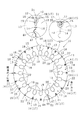
図1〜図3に示すように、本発明の第1の実施例に係る積層鉄心10は、隣り合うセグメント鉄心片13が連結部12で連結された帯状鉄心片13aを、各連結部12を折り曲げて螺旋状に巻回して積層したものである。なお、各セグメント鉄心片13を積層するに当たっては、セグメント鉄心片13の半径方向内側(スロット20)又は外側を合わせながら行うのが好ましい。この場合、隣り合うセグメント鉄心片13の側端部14には僅少の隙間が設けられてもよい。また、帯状鉄心片13aの巻回にあっては、隣り合うセグメント鉄心片13の側端部14を一致(即ち、密着)させながらセグメント鉄心片13の巻回及び積層を行ってもよい。
連結部12は連続する複数のセグメント鉄心片13を連結部12で折り曲げて円弧状又は円状とした場合、半径方向外側端部(即ち、外周)を基準として半径方向内側にセグメント鉄心片13の半径方向幅の1/30〜1/5に対応する半径幅領域(外周領域11)に形成されている。なお、連結部12は連続する複数のセグメント鉄心片13を連結部12で折り曲げて円弧状又は円状とした場合、半径方向外側端部を基準として半径方向内側に、磁極片部19を除くセグメント鉄心片13の半径方向幅の1/30〜1/2に対応する半径幅領域に形成されていてもよい。Subsequently, embodiments of the present invention will be described with reference to the accompanying drawings for understanding of the present invention.
As shown in FIGS. 1 to 3, the
When the connecting
そして、この積層鉄心10は、上下に隣接する層、即ち上下のセグメント鉄心片13に設けられた連結部12同士を周方向にずらしながら配置した固定子積層鉄心(ステータともいう)であり、連結部12を除くセグメント鉄心片13の半径方向外側に、連結部12の折り曲げ時にその厚み方向に形成される厚み方向膨出部15を入れ込む収納凹部16、17が表裏に設けられている。以下、詳しく説明する。
The
積層鉄心10は、厚みが、例えば、0.15〜0.5mm程度の電磁鋼板(図示しない)から、連結部12で結合された複数のセグメント鉄心片13を金型で打抜き、図1、図2に示すように、打抜かれた連続したセグメント鉄心片13を巻回し順次かしめ積層して構成されるものである。ここで、複数のセグメント鉄心片の積層方法としては、かしめ、溶接、及び接着のいずれか1を適用することも、また、いずれか2以上を併用することもできる。
この各セグメント鉄心片13は、円弧状のヨーク片部18とその半径方向内側に形成されている複数(この例では3)の磁極片部19とを有し、磁極片部19の間には複数のスロット20が設けられている。The
Each of the
隣り合うセグメント鉄心片13のヨーク片部18の間には、セグメント鉄心片13を外周領域11で結合する連結部12が設けられている。
この連結部12の半径方向外側には、連結部12の折り曲げ時に半径方向外側に形成される半径方向膨出部21を、積層鉄心10の外側円内に収める凹部切欠き22が設けられている。このため、図3に示すように、連結部12の折り曲げ前は、連結部12の外周が半径方向内側に凹んでいる。Between the
On the outer side in the radial direction of the connecting
また、連結部12の半径方向内側(側端部14の半径方向外側領域)には、図1、図3に示すように、連結部12の折り曲げ前の形状が円弧状となった内側切欠き23が設けられており、この内側切欠き23の最奥部24に折り曲げ起点が形成される。なお、内側切欠きの折り曲げ前の形状は、例えば、平面視して逆U字状又は逆V字状でもよい。
この内側切欠き23は、連結部12の折り曲げ後は楕円形となって、隣り合うセグメント鉄心片13間に隙間を形成するので、隣り合うセグメント鉄心片13の側端部14の半径方向内側領域を合わせる際、側端部14の半径方向外側領域同士が当接するのを防止している。Further, on the radially inner side of the connecting portion 12 (the radially outer region of the side end portion 14), as shown in FIGS. 1 and 3, an inner notch in which the shape of the connecting
The
このような連結部12で結合されたセグメント鉄心片13を、図1、図2に示すように、巻回して積層するに際しては、隣り合うセグメント鉄心片13の間に設けられた連結部12を、積層方向で異なる位置にずらし、各磁極片部19の上下方向の位置を合わせている。なお、本実施例では、セグメント鉄心片13の積層の際に、隣接する層でスロット1個分だけ周方向にずらしているが、2個以上ずつずらしてもよい。
As shown in FIGS. 1 and 2, when the
ここで、平面視した積層鉄心の一周当たりの全スロット数をm個とし、セグメント鉄心片1個当たりのスロット数(磁極片部の数と同じ)をn個とした場合、スロット1個分だけ積層方向でずらすために必要な1周のセグメント鉄心片数をk個とすると、以下の関係が成り立つ。
(m+1)/n=k
ここで、m、n、kは、それぞれ正の整数であり、積層鉄心の製造条件に応じて種々変更できる。Here, when the total number of slots per round of the laminated core in plan view is m and the number of slots per segment core piece (same as the number of magnetic pole pieces) is n, only one slot is required. When the number of segment core pieces per round necessary for shifting in the stacking direction is k, the following relationship is established.
(M + 1) / n = k
Here, m, n, and k are positive integers, respectively, and can be variously changed according to the manufacturing conditions of the laminated core.
なお、本実施例では、図1に示すように、平面視した積層鉄心の一周当たりの全スロット数が20個(m=20)、セグメント鉄心片1個当たりの磁極片部の数が3個(スロット数3個に相当:n=3)であるため、上式より1周に必要なセグメント鉄心片数は7個(k=7)であるが、7個目のセグメント鉄心片の磁極片部1個分だけ積層時に次の層となり、積層方向の連結部の位置は、磁極片部1個分(スロット1個分に相当)ずれることになる。 In this embodiment, as shown in FIG. 1, the total number of slots per round of the laminated core in plan view is 20 (m = 20), and the number of magnetic pole pieces per segment core piece is three. (Equivalent to 3 slots: n = 3) Therefore, the number of segment core pieces required for one turn from the above formula is 7 (k = 7), but the pole piece of the seventh segment core piece Only one part becomes the next layer when stacked, and the position of the connecting part in the stacking direction is shifted by one magnetic pole piece part (corresponding to one slot).
また、積層方向でずれるスロット数を2個以上にする場合は、前記した式中の「1」を、ずれる個数、即ち2以上に変えることで、1周に必要なセグメント鉄心片数が求まる。
これにより、複数のセグメント鉄心片13を巻回して積層するに際しては、連結部12の位置が積層方向でずれるため、各セグメント鉄心片13の結合強度を更に強固なものにできる。Further, when the number of slots shifted in the stacking direction is set to two or more, the number of segment core pieces necessary for one round can be obtained by changing “1” in the above formula to the shifted number, that is, two or more.
Thus, when the plurality of
このように、連結部12の位置が積層方向でずれるため、積層方向にセグメント鉄心片13と連結部12が隣り合って配置される。
そこで、連結部12を除く各セグメント鉄心片13の半径方向外側の表裏に、収納凹部16、17を実質的に等角度(ここでは、スロット20の中心線と収納凹部16、17の中心線を一致させる位置)に設け、連結部12の折り曲げ後に、その厚み方向に形成される厚み方向膨出部15が、積層方向に隣り合うセグメント鉄心片13の収納凹部16、17内に収まるようにしている。
このように、収納凹部16、17は、各セグメント鉄心片13の隣り合う磁極片部19の間に形成されるU字状のスロット20の中心線上に設けられ、しかも連結部12の半径方向の位置と同一の半径方向位置に形成されている。Thus, since the position of the
Therefore, the storage recesses 16 and 17 are formed at substantially equal angles (here, the center line of the
As described above, the storage recesses 16 and 17 are provided on the center line of the
各収納凹部16、17は、円錐台状となってその中心には、各収納凹部16、17をプレス加工することによって発生する余剰金属を逃がす貫通孔25が設けられている。なお、この貫通孔25の形成の後に、各収納凹部16、17をパンチ加工するのが好ましい。
各収納凹部16、17の外側直径は、例えば、連結部12の半径方向の最小幅の1〜5倍の範囲にあって、その深さはセグメント鉄心片13の厚みの0.15〜0.3倍の範囲にある。なお、貫通孔25の直径は、各収納凹部16、17の最大幅(外側直径)の1/4〜1/2の範囲にある。
このとき、貫通孔25の体積は、貫通孔25を除く表裏の収納凹部16、17の合計体積の0.7〜1.5倍の範囲にあるのが好ましいが、この倍率が0.7より小さい場合であっても、また1.5倍より大きい場合であっても、本発明は適用される。Each of the storage recesses 16 and 17 has a truncated cone shape, and a through
The outer diameters of the storage recesses 16 and 17 are, for example, in the range of 1 to 5 times the minimum radial width of the connecting
At this time, the volume of the through-
なお、セグメント鉄心片13の所定位置に収納凹部16、17と貫通孔25を設けることによって、連結部12を折り曲げた場合に発生する厚み方向膨出部15を、収納凹部16、17内に収納できる。
これによって、積層鉄心10の高さを均一に保つことができ、製品寸法が向上し、使用時に振動や騒音の発生を防止できる。
また、図4(A)〜(J)には、収納凹部の変形例を示すが、(A)〜(E)は中央に貫通孔が設けられていない収納凹部26〜35を示し、それぞれ表裏に設けられている窪みが、円錐、四角錐、高さの低い円柱、高さの低い角柱、半球(部分球)となっている。In addition, by providing the storage recesses 16 and 17 and the through
As a result, the height of the
4A to 4J show modified examples of the storage recesses. FIGS. 4A to 4E show the storage recesses 26 to 35 in which no through hole is provided in the center. The dents provided in are a cone, a quadrangular pyramid, a low height cylinder, a low height prism, and a hemisphere (partial sphere).
また、(F)〜(J)に示す収納凹部36〜45は中央に貫通孔が設けられ、それぞれ窪みが、六角錐台、四角錐台、高さの低い円柱、高さの低い角柱、半球を示す。
ここで、四角錐と高さの低い角柱は、平面視して多角形であるが、この多角形は、三角形又は五角形以上でもよい。
これらの場合、いずれも、連結部12を折り曲げた場合に発生する厚み方向膨出部15の高さより、各収納凹部の深さが同一又は深いことが好ましい。In addition, the storage recesses 36 to 45 shown in (F) to (J) are provided with a through hole in the center, and each of the recesses has a hexagonal frustum, a quadrangular frustum, a low height cylinder, a low height prism, and a hemisphere. Indicates.
Here, the quadrangular pyramid and the low-profile prism are polygonal in plan view, but the polygon may be a triangle or a pentagon or more.
In any of these cases, it is preferable that the depth of each storage recess is the same or deeper than the height of the bulging
以上のように構成することで、連結部12を折り曲げる際に、連結部12に設けられた内側切欠き23が、連結部12に良好なヒンジ効果を与えることができる。
また、この連結部12は、折り曲げ時に、連結部12の外周領域が円周方向に引っ張られ、その厚みが薄くなると共に半径方向外側に半径方向膨出部21が形成されるが、これは凹部切欠き22内に配置されるため問題ない。一方、連結部12の内周部は円周方向に押し縮められ、その厚み方向に厚み方向膨出部15が形成されるが、これは下側に隣接するセグメント鉄心片13の収納凹部16と、上側に隣接するセグメント鉄心片13の収納凹部17内に配置されるため問題ない。By configuring as described above, the
Further, when the connecting
なお、隣り合うセグメント鉄心片13の側端部14の半径方向内側領域には、凹部46とこれに嵌合する凸部47によって構成される係合部48が設けられている。この凹部46と凸部47を含む隣り合うセグメント鉄心片13の側端部14は、隙間を開けて近接配置されているが、当接させてもよい。
これにより、隣り合うセグメント鉄心片13同士の相互の位置決めをより精度良く実施でき、その環状精度を向上できる。In addition, an engaging
Thereby, the mutual positioning of the adjacent
ここで、隣り合うセグメント鉄心片の側端部を少しの隙間を有して近接配置する場合、セグメント鉄心片の側端部同士の接触が防止されるので、各セグメント鉄心片の周方向のピッチのばらつきをこの隙間を調整して防止でき、例えば、積層方向のセグメント鉄心片のかしめ位置のずれを防止できる。また、このように隣合うセグメント鉄心片の側端部を近接配置することにより、例えば、セグメント鉄心片を打抜く金型の刃物が摩耗し、側端部にバリが生じた場合でも、その接触を防止でき、各セグメント鉄心片の周方向のピッチのずれを防止できる。 Here, when the side ends of adjacent segment core pieces are arranged close to each other with a slight gap, the contact between the side ends of the segment core pieces is prevented, so the pitch in the circumferential direction of each segment core piece Thus, for example, it is possible to prevent the displacement of the caulking position of the segment core pieces in the stacking direction. Further, by arranging the side end portions of the adjacent segment core pieces in this way, for example, even when the cutting tool of the die punching the segment core pieces is worn and burrs are generated at the side end portions, the contact is made. And the shift of the pitch in the circumferential direction of each segment core piece can be prevented.
続いて、本発明の第1の実施例に係る積層鉄心の製造方法について説明する。
まず、電磁鋼板(図示しない)を搬送しながら、1又は複数の金型(図示しない)を使用して、図3に示すように、連結部12で相互に結合された複数のセグメント鉄心片13を打抜く。
このセグメント鉄心片13の打抜きに際しては、通常行うスロット20の打抜き形成の後に、凹部切欠き22を形成するA工程と、内側切欠き23を形成するB工程と、収納凹部16、17を形成するC工程を行う。このC工程では、収納凹部16、17を形成する前に、予め貫通孔25を形成する。
なお、金型形状によって、各A〜C工程を同時に行うことも、順次個別に行うことも、また順序を入れ換えて行うことも可能であり、更にスロット20の打抜き形成と共に行うことも可能である。Then, the manufacturing method of the laminated core which concerns on the 1st Example of this invention is demonstrated.
First, as shown in FIG. 3, a plurality of
When the
Depending on the mold shape, each of the A to C steps can be performed simultaneously, individually, or by changing the order, and can be performed together with the punching of the
そして、内側切欠き23の最奥部24を起点として連結部12を折り曲げ、隣り合うセグメント鉄心片13の凹部46に凸部47を嵌合させると共に、セグメント鉄心片13の内側の側端部14を合わせて、かつ磁極片部19を重合させながら、連続した複数のセグメント鉄心片13を螺旋状に巻回し、連結部12を積層方向にずらしながら積層して積層鉄心10を製造する。なお、セグメント鉄心片13の内側を所定直径の円柱体に巻き付けて、螺旋状に巻くのが好ましい。
Then, the connecting
ここで、セグメント鉄心片13の半径方向外側に形成された収納凹部16、17内には、積層方向に隣り合う連結部12の厚み方向膨出部15がそれぞれ配置され、厚み方向膨出部15をセグメント鉄心片13の板厚内に収めることができ、積層方向に隣り合うセグメント鉄心片の間の隙間発生を防止できる。
Here, in the storage recesses 16 and 17 formed on the outer side in the radial direction of the
次に、図5を参照しながら、本発明の第2の実施例に係る積層鉄心及びその製造方法について説明する。
図5に示すように、このセグメント鉄心片50を螺旋状に巻いて形成されるものは、回転子積層鉄心(図示せず)であって、各セグメント鉄心片50にはヨーク片部51の半径方向外側に複数(この実施例では2)の永久磁石取付け部の一例である永久磁石挿入孔52、53を有している。この永久磁石挿入孔52、53の部分が回転子の磁極となる部分である。Next, a laminated core and a method for manufacturing the same according to a second embodiment of the present invention will be described with reference to FIG.
As shown in FIG. 5, the
隣り合うセグメント鉄心片50のヨーク片部51は、セグメント鉄心片50の外周を基準として半径方向内側で、セグメント鉄心片50の半径方向最大幅の1/30〜1/5(又は1/30〜1/2)に対応する半径幅領域である外周領域54に位置する連結部55で連結されている。そして、連結部55の半径方向外側には凹部切欠き56を有している。また、連結部55の半径方向内側には、連結部55の折り曲げ位置を形成する内側切欠き57を設けている。
The
セグメント鉄心片50において、連結部55を除くヨーク片部51の半径方向外側であって、隣り合う永久磁石挿入孔52、53の間には、連結部55を折り曲げる巻回時に、連結部55の厚み方向に形成される厚み方向膨出部を入れ込む収納凹部57aを表裏に設けている。この収納凹部57aの中央には貫通孔が形成されている。なお、連結部55、収納凹部57aの形状等については、セグメント鉄心片13と同様である(図2参照)。
In the
隣り合うセグメント鉄心片50の側端部58には、凹部59と凸部60で形成される位置決め係合部が形成されている。また、磁極部を構成する永久磁石挿入孔52、53の半径方向内側でその中央には、掛止凹部62が形成され、隣り合うセグメント鉄心片50の側端部58で半径方向内側には、対向する切欠き63、64によって形成される掛止凹部65が形成され、連結部55で連結された複数のセグメント鉄心片50からなる帯状鉄心片66を螺旋状に巻回した場合には、上下の掛止凹部62、65が重なるようになっている。
A positioning engagement portion formed by the
セグメント鉄心片50の磁極部の中央位置で半径方向内側のヨーク片部51には、パイロット孔あるいはボルト孔として使用される丸孔67が、その両側にかしめ部68が形成されている。
以上の構成となった帯状鉄心片66を、周囲に掛止凸条が所定ピッチで設けられた巻き取り軸(図示せず)によって巻き取る。なお、掛止凸条には掛止凹部62、65が嵌入する。この場合、隣り合うセグメント鉄心片50の側端部58は当接する場合もあるが、僅少の隙間があってもよい。A
The strip-shaped
以上、本発明を、実施例を参照して説明してきたが、本発明は何ら上記した実施例に記載の構成に限定されるものではなく、請求の範囲に記載されている事項の範囲内で考えられるその他の実施例や変形例も含むものである。例えば、前記したそれぞれの実施例や変形例の一部又は全部を組合せて本発明の積層鉄心及びその製造方法を構成する場合も本発明の権利範囲に含まれる。 The present invention has been described with reference to the embodiments. However, the present invention is not limited to the configurations described in the above-described embodiments, and is within the scope of the matters described in the claims. Other possible embodiments and modifications are also included. For example, the case where the laminated core of the present invention and the manufacturing method thereof are configured by combining some or all of the above-described embodiments and modifications are also included in the scope of the right of the present invention.
本発明に係る積層鉄心をモータや発電機の固定子又は回転子に適用して、製造価格が安価で精度の高い製品を提供できる。 By applying the laminated iron core according to the present invention to a stator or a rotor of a motor or a generator, a product with a low manufacturing price and high accuracy can be provided.
Claims (15)
前記連結部の半径方向外側には該連結部の折り曲げ時に半径方向外側に形成される半径方向膨出部を該積層鉄心の外側円内に収める凹部切欠きを有し、
前記連結部の半径方向内側には、該連結部の折り曲げ位置を形成する内側切欠きを設け、前記連結部を除く前記セグメント鉄心片の半径方向外側には、前記連結部の折り曲げ時にその厚み方向に形成される厚み方向膨出部を入れ込む収納凹部を表裏に設けることを特徴とする積層鉄心。While bending the connecting portions of adjacent segment core pieces joined to each other at the connecting portions formed in the outer peripheral region, the end portions on the inner side or the outer side in the radial direction of the segment core pieces are matched to each other, In the laminated core disposed by spirally winding the segment core pieces and arranging the connecting portions provided in adjacent layers while shifting in the circumferential direction,
On the outer side in the radial direction of the connecting part, there is a recess notch that accommodates a radially bulging part formed on the outer side in the radial direction when the connecting part is bent in an outer circle of the laminated core,
An inner notch for forming a bending position of the connecting portion is provided on the radially inner side of the connecting portion, and the thickness direction of the segment core core piece excluding the connecting portion is increased when the connecting portion is bent. The laminated iron core is characterized in that storage recesses for inserting the bulging portions in the thickness direction formed on the front and back are provided.
前記セグメント鉄心片の形成に際し、前記連結部の半径方向外側に、該連結部の折り曲げ時に半径方向外側に形成される半径方向膨出部を該積層鉄心の外側円内に嵌め込む凹部切欠きを形成するA工程と、
前記連結部の半径方向内側に該連結部の折り曲げ位置を決める内側切欠きを形成するB工程と、
前記連結部を除く前記セグメント鉄心片の半径方向外側に、前記連結部の折り曲げ時にその厚み方向に形成される厚み方向膨出部を嵌め込む収納凹部を形成するC工程とを行うことを特徴とする積層鉄心の製造方法。A plurality of continuous segments are formed by forming a plurality of segment core pieces joined together by connecting portions formed in an outer peripheral region, and bending the connecting portions to align side end portions of adjacent segment core pieces. In the method of manufacturing a laminated core, in which the core pieces are spirally wound and laminated, and the connecting portions provided in adjacent layers are arranged while being shifted in the circumferential direction.
When forming the segment core piece, a recess notch is formed on the radially outer side of the connecting portion to fit the radially bulging portion formed on the radially outer side when the connecting portion is bent into the outer circle of the laminated core. A step to be formed;
B step of forming an inner notch for determining a bending position of the connecting portion on the radially inner side of the connecting portion;
And performing a C step of forming a storage recess into which a bulge portion in the thickness direction formed in the thickness direction when the connecting portion is bent is formed on the outer side in the radial direction of the segment core piece excluding the connecting portion. A method for manufacturing a laminated core.
前記セグメント鉄心片の形成に際し、前記連結部の半径方向外側に、該連結部の折り曲げ時に半径方向外側に形成される半径方向膨出部を該積層鉄心の外側円内に嵌め込む凹部切欠きを形成するA工程と、
前記連結部の半径方向内側に該連結部の折り曲げ位置を決める内側切欠きを形成するB工程と、
前記連結部を除く前記セグメント鉄心片の半径方向外側に、前記連結部の折り曲げ時にその厚み方向に形成される厚み方向膨出部を嵌め込む収納凹部を形成するC工程とを行うことを特徴とする積層鉄心の製造方法。A plurality of continuous segment segments are formed by forming a plurality of segment core pieces joined together by connecting portions formed in an outer peripheral region, and bending the connecting portions to align the inside or outside of the adjacent segment core pieces. In the method of manufacturing a laminated core, in which the core pieces are spirally wound and laminated, and the connecting portions provided in adjacent layers are arranged while being shifted in the circumferential direction.
When forming the segment core piece, a recess notch is formed on the radially outer side of the connecting portion to fit the radially bulging portion formed on the radially outer side when the connecting portion is bent into the outer circle of the laminated core. A step to be formed;
B step of forming an inner notch for determining a bending position of the connecting portion on the radially inner side of the connecting portion;
And performing a C step of forming a storage recess into which a bulge portion in the thickness direction formed in the thickness direction when the connecting portion is bent is formed on the outer side in the radial direction of the segment core piece excluding the connecting portion. A method for manufacturing a laminated core.
Priority Applications (1)
| Application Number | Priority Date | Filing Date | Title |
|---|---|---|---|
| JP2009514059A JP5129810B2 (en) | 2007-05-09 | 2008-04-21 | Laminated iron core and method for manufacturing the same |
Applications Claiming Priority (4)
| Application Number | Priority Date | Filing Date | Title |
|---|---|---|---|
| JP2007124822 | 2007-05-09 | ||
| JP2007124822 | 2007-05-09 | ||
| PCT/JP2008/057697 WO2008139843A1 (en) | 2007-05-09 | 2008-04-21 | Laminated iron core, and its manufacturing method |
| JP2009514059A JP5129810B2 (en) | 2007-05-09 | 2008-04-21 | Laminated iron core and method for manufacturing the same |
Publications (2)
| Publication Number | Publication Date |
|---|---|
| JPWO2008139843A1 JPWO2008139843A1 (en) | 2010-07-29 |
| JP5129810B2 true JP5129810B2 (en) | 2013-01-30 |
Family
ID=40002061
Family Applications (1)
| Application Number | Title | Priority Date | Filing Date |
|---|---|---|---|
| JP2009514059A Expired - Fee Related JP5129810B2 (en) | 2007-05-09 | 2008-04-21 | Laminated iron core and method for manufacturing the same |
Country Status (5)
| Country | Link |
|---|---|
| US (1) | US8106561B2 (en) |
| EP (1) | EP2146417B1 (en) |
| JP (1) | JP5129810B2 (en) |
| CN (1) | CN101682219B (en) |
| WO (1) | WO2008139843A1 (en) |
Families Citing this family (36)
| Publication number | Priority date | Publication date | Assignee | Title |
|---|---|---|---|---|
| JP5620126B2 (en) * | 2009-05-15 | 2014-11-05 | 株式会社三井ハイテック | Laminated iron core |
| JP5335633B2 (en) * | 2009-09-24 | 2013-11-06 | 三菱電機株式会社 | Rotating electric machine and method of manufacturing rotating electric machine |
| JP5462675B2 (en) * | 2010-03-17 | 2014-04-02 | 株式会社三井ハイテック | Manufacturing method of laminated iron core |
| JP2012120299A (en) * | 2010-11-30 | 2012-06-21 | Mitsubishi Electric Corp | Stator core, rotary electric machine, and manufacturing method of stator core |
| PL2670030T3 (en) * | 2011-01-28 | 2019-08-30 | Nippon Steel & Sumitomo Metal Corporation | Manufacturing method for helical core for rotating electrical machine and manufacturing device for helical core for rotating electrical machine |
| US20130033146A1 (en) * | 2011-08-04 | 2013-02-07 | Mark Bender | Segmented rotor and stator lamination cores |
| JP5862145B2 (en) * | 2011-09-19 | 2016-02-16 | 日本電産株式会社 | Motor and motor manufacturing method |
| US8917004B2 (en) | 2011-12-07 | 2014-12-23 | Rotonix Hong Kong Limited | Homopolar motor-generator |
| JP5908285B2 (en) * | 2012-01-19 | 2016-04-26 | 株式会社三井ハイテック | Manufacturing method of laminated iron core |
| US8941274B2 (en) | 2012-03-23 | 2015-01-27 | Whirlpool Corporation | Stator for an electric motor of a washing machine and method of manufacturing the same |
| US20130269665A1 (en) * | 2012-04-16 | 2013-10-17 | Mark Bender | Ignition coil and manufacturing method |
| JP5957360B2 (en) * | 2012-10-23 | 2016-07-27 | 株式会社三井ハイテック | Manufacturing method of laminated iron core |
| EP2942857A1 (en) * | 2014-05-07 | 2015-11-11 | Pierburg Pump Technology GmbH | Electrical auxiliary unit for a motor vehicle |
| KR101679470B1 (en) * | 2014-05-16 | 2016-11-25 | 뉴모텍(주) | Laminated Core for Motor and Method for Manufacturing the Same |
| JP2017038453A (en) * | 2015-08-07 | 2017-02-16 | 株式会社三井ハイテック | Laminated core, manufacturing method thereof, and punch for caulk formation used therefor |
| EP3484016A4 (en) * | 2016-07-08 | 2020-03-04 | Nisso Electric Corporation | Motor stator, motor stator manufacturing method, and motor |
| WO2018198562A1 (en) * | 2017-04-27 | 2018-11-01 | 三菱電機株式会社 | Rotary electrical machine stator core, stator, rotary electrical machine, fluid pump, method for manufacturing rotary electrical machine stator core, and method for manufacturing stator |
| JP6972138B2 (en) * | 2017-08-25 | 2021-11-24 | 三菱電機株式会社 | Manufacturing method of split core connector and armature |
| WO2019087358A1 (en) * | 2017-11-02 | 2019-05-09 | 三菱電機株式会社 | Armature core of rotary electric machine and manufacturing method for armature core of rotary electric machine |
| DE102018205806A1 (en) * | 2018-04-17 | 2019-10-17 | Siemens Aktiengesellschaft | Stator, electric machine, aircraft with an electric machine and method of manufacturing a stator |
| US10879775B2 (en) * | 2018-05-23 | 2020-12-29 | Ford Global Technologies, Llc | Surface treatments of electrical steel core devices |
| CN110971029B (en) * | 2018-09-28 | 2022-03-01 | 佛山市威灵洗涤电机制造有限公司 | Rotor punching sheet, rotor and motor |
| US11979059B2 (en) | 2018-12-17 | 2024-05-07 | Nippon Steel Corporation | Laminated core and electric motor |
| WO2020129924A1 (en) * | 2018-12-17 | 2020-06-25 | 日本製鉄株式会社 | Laminated core and rotating electric machine |
| WO2020129946A1 (en) | 2018-12-17 | 2020-06-25 | 日本製鉄株式会社 | Glue lamination core for stators and method for manufacturing same, and rotating electrical machine |
| US12068097B2 (en) | 2018-12-17 | 2024-08-20 | Nippon Steel Corporation | Laminated core, core block, electric motor and method of producing core block |
| CA3131659C (en) | 2018-12-17 | 2023-11-14 | Nippon Steel Corporation | Adhesively-laminated core for stator and electric motor |
| KR102643516B1 (en) | 2018-12-17 | 2024-03-06 | 닛폰세이테츠 가부시키가이샤 | Laminated core and rotating electric machines |
| JP7412351B2 (en) | 2018-12-17 | 2024-01-12 | 日本製鉄株式会社 | Laminated core and rotating electrical machinery |
| EP3902108B1 (en) | 2018-12-17 | 2024-06-12 | Nippon Steel Corporation | Laminated core and rotating electric machine |
| PL3902122T3 (en) | 2018-12-17 | 2024-06-24 | Nippon Steel Corporation | Laminated core and electric motor |
| CN109599963A (en) * | 2019-01-17 | 2019-04-09 | 日立电梯电机(广州)有限公司 | Core body, stator and motor |
| JP7278398B2 (en) * | 2019-10-02 | 2023-05-19 | 三菱電機株式会社 | Rotating electric machine |
| CN115398776A (en) * | 2020-04-01 | 2022-11-25 | 发那科株式会社 | Stator, rotor, and rotating electrical machine |
| JP2022082266A (en) * | 2020-11-20 | 2022-06-01 | ミネベアミツミ株式会社 | motor |
| CN114400846B (en) * | 2022-01-24 | 2023-11-24 | 重庆市美庆科技有限公司 | Rotor core manufacturing method |
Citations (6)
| Publication number | Priority date | Publication date | Assignee | Title |
|---|---|---|---|---|
| JPH08196061A (en) * | 1995-01-12 | 1996-07-30 | Mitsui High Tec Inc | Laminated core for stator |
| JPH11262202A (en) * | 1998-03-12 | 1999-09-24 | Techno Excel Co Ltd | Iron core material for stacking |
| JPH11289695A (en) * | 1998-03-31 | 1999-10-19 | Toshiba Corp | Electric motor core |
| JP2004505595A (en) * | 2000-08-01 | 2004-02-19 | アーベーベー・リサーチ・リミテッド | Rotating electric machine and method of forming the same |
| JP2005168128A (en) * | 2003-12-01 | 2005-06-23 | Honda Motor Co Ltd | Rotor for rotary electric machine |
| JP2007143257A (en) * | 2005-11-16 | 2007-06-07 | Mitsui High Tec Inc | Laminated iron core and manufacturing method of the same |
Family Cites Families (11)
| Publication number | Priority date | Publication date | Assignee | Title |
|---|---|---|---|---|
| JPH01264548A (en) | 1988-04-11 | 1989-10-20 | Toshiba Corp | Manufacture of annular core |
| JP3279279B2 (en) * | 1998-06-30 | 2002-04-30 | 三菱電機株式会社 | Iron core equipment |
| JP3730218B2 (en) * | 2000-08-29 | 2005-12-21 | 三菱電機株式会社 | Stacked stator core and manufacturing method thereof, and rotary motor and manufacturing method thereof |
| JP2005160170A (en) * | 2003-11-21 | 2005-06-16 | Fujitsu General Ltd | Motor |
| KR101033580B1 (en) * | 2004-03-03 | 2011-05-11 | 엘지전자 주식회사 | structure and manufacturing method for spiral core |
| JP2006025533A (en) * | 2004-07-07 | 2006-01-26 | Mitsui High Tec Inc | Caulking structure of laminated iron core |
| JP4654012B2 (en) * | 2004-12-02 | 2011-03-16 | 株式会社三井ハイテック | Manufacturing method of laminated iron core |
| JP4681954B2 (en) * | 2005-06-09 | 2011-05-11 | 株式会社三井ハイテック | Manufacturing method of laminated iron core and laminated iron core |
| JP2007014050A (en) * | 2005-06-28 | 2007-01-18 | Jtekt Corp | Core of rotary machine and its manufacturing process |
| JP2007049774A (en) * | 2005-08-05 | 2007-02-22 | Asmo Co Ltd | Brushless motor, and stator |
| JP2007068310A (en) * | 2005-08-30 | 2007-03-15 | Aisin Seiki Co Ltd | Laminated winding core for rotary machine |
-
2008
- 2008-04-21 CN CN200880015107.6A patent/CN101682219B/en not_active Expired - Fee Related
- 2008-04-21 JP JP2009514059A patent/JP5129810B2/en not_active Expired - Fee Related
- 2008-04-21 WO PCT/JP2008/057697 patent/WO2008139843A1/en active Application Filing
- 2008-04-21 US US12/527,784 patent/US8106561B2/en not_active Expired - Fee Related
- 2008-04-21 EP EP08740739.1A patent/EP2146417B1/en not_active Not-in-force
Patent Citations (6)
| Publication number | Priority date | Publication date | Assignee | Title |
|---|---|---|---|---|
| JPH08196061A (en) * | 1995-01-12 | 1996-07-30 | Mitsui High Tec Inc | Laminated core for stator |
| JPH11262202A (en) * | 1998-03-12 | 1999-09-24 | Techno Excel Co Ltd | Iron core material for stacking |
| JPH11289695A (en) * | 1998-03-31 | 1999-10-19 | Toshiba Corp | Electric motor core |
| JP2004505595A (en) * | 2000-08-01 | 2004-02-19 | アーベーベー・リサーチ・リミテッド | Rotating electric machine and method of forming the same |
| JP2005168128A (en) * | 2003-12-01 | 2005-06-23 | Honda Motor Co Ltd | Rotor for rotary electric machine |
| JP2007143257A (en) * | 2005-11-16 | 2007-06-07 | Mitsui High Tec Inc | Laminated iron core and manufacturing method of the same |
Also Published As
| Publication number | Publication date |
|---|---|
| US20100090560A1 (en) | 2010-04-15 |
| EP2146417A4 (en) | 2014-07-02 |
| US8106561B2 (en) | 2012-01-31 |
| JPWO2008139843A1 (en) | 2010-07-29 |
| CN101682219B (en) | 2012-07-25 |
| EP2146417A1 (en) | 2010-01-20 |
| WO2008139843A1 (en) | 2008-11-20 |
| EP2146417B1 (en) | 2016-08-17 |
| CN101682219A (en) | 2010-03-24 |
Similar Documents
| Publication | Publication Date | Title |
|---|---|---|
| JP5129810B2 (en) | Laminated iron core and method for manufacturing the same | |
| US7777387B2 (en) | Laminated core and method for manufacturing the same | |
| JP4932967B1 (en) | Manufacturing method of spiral core for rotating electrical machine and manufacturing apparatus of spiral core for rotating electrical machine | |
| JP3989510B2 (en) | Laminated iron core and method for manufacturing the same | |
| JP4983695B2 (en) | Stator core manufacturing method | |
| JP5469307B2 (en) | Rotor laminated iron core | |
| JP4611272B2 (en) | Laminated iron core and method for manufacturing the same | |
| JP4150397B2 (en) | Laminated iron core and method for manufacturing the same | |
| JP5237988B2 (en) | Laminated iron core and method for manufacturing the same | |
| JP5717973B2 (en) | Laminated iron core and method for manufacturing the same | |
| JP5358517B2 (en) | Manufacturing method of laminated iron core | |
| JP5251384B2 (en) | Laminated core and manufacturing method thereof | |
| JP4242435B2 (en) | Laminated iron core and method for manufacturing the same | |
| JP5390869B2 (en) | Laminated iron core and method for manufacturing the same | |
| JP6727458B2 (en) | Stator core and electric motor equipped with the stator core | |
| JP4557867B2 (en) | Laminated iron core and method for manufacturing the same | |
| JP2009131027A (en) | Laminated core and its manufacturing method | |
| US11870304B2 (en) | Rotary electric machine with tubular housing and flange | |
| KR100531903B1 (en) | External-tooth type stator core | |
| JP7133803B2 (en) | Manufacturing method of housing for rotary electric machine | |
| JP2008278598A (en) | Method of manufacturing laminated core, and laminated core manufactured thereby | |
| JP2012135091A (en) | Laminated iron core and method for manufacturing the same |
Legal Events
| Date | Code | Title | Description |
|---|---|---|---|
| A621 | Written request for application examination |
Free format text: JAPANESE INTERMEDIATE CODE: A621 Effective date: 20101216 |
|
| TRDD | Decision of grant or rejection written | ||
| A01 | Written decision to grant a patent or to grant a registration (utility model) |
Free format text: JAPANESE INTERMEDIATE CODE: A01 Effective date: 20121030 |
|
| A01 | Written decision to grant a patent or to grant a registration (utility model) |
Free format text: JAPANESE INTERMEDIATE CODE: A01 |
|
| A61 | First payment of annual fees (during grant procedure) |
Free format text: JAPANESE INTERMEDIATE CODE: A61 Effective date: 20121102 |
|
| R150 | Certificate of patent or registration of utility model |
Free format text: JAPANESE INTERMEDIATE CODE: R150 |
|
| FPAY | Renewal fee payment (event date is renewal date of database) |
Free format text: PAYMENT UNTIL: 20151109 Year of fee payment: 3 |
|
| R250 | Receipt of annual fees |
Free format text: JAPANESE INTERMEDIATE CODE: R250 |
|
| R250 | Receipt of annual fees |
Free format text: JAPANESE INTERMEDIATE CODE: R250 |
|
| R250 | Receipt of annual fees |
Free format text: JAPANESE INTERMEDIATE CODE: R250 |
|
| LAPS | Cancellation because of no payment of annual fees |