WO2017222013A1 - 回転検出装置及びセンサ付きケーブル - Google Patents
回転検出装置及びセンサ付きケーブル Download PDFInfo
- Publication number
- WO2017222013A1 WO2017222013A1 PCT/JP2017/023030 JP2017023030W WO2017222013A1 WO 2017222013 A1 WO2017222013 A1 WO 2017222013A1 JP 2017023030 W JP2017023030 W JP 2017023030W WO 2017222013 A1 WO2017222013 A1 WO 2017222013A1
- Authority
- WO
- WIPO (PCT)
- Prior art keywords
- magnetic
- sensor
- rotation
- cable
- detected
- Prior art date
- Legal status (The legal status is an assumption and is not a legal conclusion. Google has not performed a legal analysis and makes no representation as to the accuracy of the status listed.)
- Ceased
Links
Images





Classifications
-
- G—PHYSICS
- G01—MEASURING; TESTING
- G01D—MEASURING NOT SPECIALLY ADAPTED FOR A SPECIFIC VARIABLE; ARRANGEMENTS FOR MEASURING TWO OR MORE VARIABLES NOT COVERED IN A SINGLE OTHER SUBCLASS; TARIFF METERING APPARATUS; MEASURING OR TESTING NOT OTHERWISE PROVIDED FOR
- G01D5/00—Mechanical means for transferring the output of a sensing member; Means for converting the output of a sensing member to another variable where the form or nature of the sensing member does not constrain the means for converting; Transducers not specially adapted for a specific variable
- G01D5/12—Mechanical means for transferring the output of a sensing member; Means for converting the output of a sensing member to another variable where the form or nature of the sensing member does not constrain the means for converting; Transducers not specially adapted for a specific variable using electric or magnetic means
- G01D5/14—Mechanical means for transferring the output of a sensing member; Means for converting the output of a sensing member to another variable where the form or nature of the sensing member does not constrain the means for converting; Transducers not specially adapted for a specific variable using electric or magnetic means influencing the magnitude of a current or voltage
- G01D5/142—Mechanical means for transferring the output of a sensing member; Means for converting the output of a sensing member to another variable where the form or nature of the sensing member does not constrain the means for converting; Transducers not specially adapted for a specific variable using electric or magnetic means influencing the magnitude of a current or voltage using Hall-effect devices
-
- G—PHYSICS
- G01—MEASURING; TESTING
- G01D—MEASURING NOT SPECIALLY ADAPTED FOR A SPECIFIC VARIABLE; ARRANGEMENTS FOR MEASURING TWO OR MORE VARIABLES NOT COVERED IN A SINGLE OTHER SUBCLASS; TARIFF METERING APPARATUS; MEASURING OR TESTING NOT OTHERWISE PROVIDED FOR
- G01D5/00—Mechanical means for transferring the output of a sensing member; Means for converting the output of a sensing member to another variable where the form or nature of the sensing member does not constrain the means for converting; Transducers not specially adapted for a specific variable
- G01D5/12—Mechanical means for transferring the output of a sensing member; Means for converting the output of a sensing member to another variable where the form or nature of the sensing member does not constrain the means for converting; Transducers not specially adapted for a specific variable using electric or magnetic means
- G01D5/14—Mechanical means for transferring the output of a sensing member; Means for converting the output of a sensing member to another variable where the form or nature of the sensing member does not constrain the means for converting; Transducers not specially adapted for a specific variable using electric or magnetic means influencing the magnitude of a current or voltage
- G01D5/142—Mechanical means for transferring the output of a sensing member; Means for converting the output of a sensing member to another variable where the form or nature of the sensing member does not constrain the means for converting; Transducers not specially adapted for a specific variable using electric or magnetic means influencing the magnitude of a current or voltage using Hall-effect devices
- G01D5/145—Mechanical means for transferring the output of a sensing member; Means for converting the output of a sensing member to another variable where the form or nature of the sensing member does not constrain the means for converting; Transducers not specially adapted for a specific variable using electric or magnetic means influencing the magnitude of a current or voltage using Hall-effect devices influenced by the relative movement between the Hall device and magnetic fields
-
- G—PHYSICS
- G01—MEASURING; TESTING
- G01P—MEASURING LINEAR OR ANGULAR SPEED, ACCELERATION, DECELERATION, OR SHOCK; INDICATING PRESENCE, ABSENCE, OR DIRECTION, OF MOVEMENT
- G01P3/00—Measuring linear or angular speed; Measuring differences of linear or angular speeds
- G01P3/42—Devices characterised by the use of electric or magnetic means
- G01P3/44—Devices characterised by the use of electric or magnetic means for measuring angular speed
- G01P3/48—Devices characterised by the use of electric or magnetic means for measuring angular speed by measuring frequency of generated current or voltage
- G01P3/481—Devices characterised by the use of electric or magnetic means for measuring angular speed by measuring frequency of generated current or voltage of pulse signals
- G01P3/487—Devices characterised by the use of electric or magnetic means for measuring angular speed by measuring frequency of generated current or voltage of pulse signals delivered by rotating magnets
-
- B—PERFORMING OPERATIONS; TRANSPORTING
- B60—VEHICLES IN GENERAL
- B60T—VEHICLE BRAKE CONTROL SYSTEMS OR PARTS THEREOF; BRAKE CONTROL SYSTEMS OR PARTS THEREOF, IN GENERAL; ARRANGEMENT OF BRAKING ELEMENTS ON VEHICLES IN GENERAL; PORTABLE DEVICES FOR PREVENTING UNWANTED MOVEMENT OF VEHICLES; VEHICLE MODIFICATIONS TO FACILITATE COOLING OF BRAKES
- B60T8/00—Arrangements for adjusting wheel-braking force to meet varying vehicular or ground-surface conditions, e.g. limiting or varying distribution of braking force
- B60T8/17—Using electrical or electronic regulation means to control braking
- B60T8/171—Detecting parameters used in the regulation; Measuring values used in the regulation
-
- F—MECHANICAL ENGINEERING; LIGHTING; HEATING; WEAPONS; BLASTING
- F16—ENGINEERING ELEMENTS AND UNITS; GENERAL MEASURES FOR PRODUCING AND MAINTAINING EFFECTIVE FUNCTIONING OF MACHINES OR INSTALLATIONS; THERMAL INSULATION IN GENERAL
- F16C—SHAFTS; FLEXIBLE SHAFTS; ELEMENTS OR CRANKSHAFT MECHANISMS; ROTARY BODIES OTHER THAN GEARING ELEMENTS; BEARINGS
- F16C19/00—Bearings with rolling contact, for exclusively rotary movement
- F16C19/02—Bearings with rolling contact, for exclusively rotary movement with bearing balls essentially of the same size in one or more circular rows
- F16C19/14—Bearings with rolling contact, for exclusively rotary movement with bearing balls essentially of the same size in one or more circular rows for both radial and axial load
- F16C19/18—Bearings with rolling contact, for exclusively rotary movement with bearing balls essentially of the same size in one or more circular rows for both radial and axial load with two or more rows of balls
-
- F—MECHANICAL ENGINEERING; LIGHTING; HEATING; WEAPONS; BLASTING
- F16—ENGINEERING ELEMENTS AND UNITS; GENERAL MEASURES FOR PRODUCING AND MAINTAINING EFFECTIVE FUNCTIONING OF MACHINES OR INSTALLATIONS; THERMAL INSULATION IN GENERAL
- F16C—SHAFTS; FLEXIBLE SHAFTS; ELEMENTS OR CRANKSHAFT MECHANISMS; ROTARY BODIES OTHER THAN GEARING ELEMENTS; BEARINGS
- F16C41/00—Other accessories, e.g. devices integrated in the bearing not relating to the bearing function as such
-
- G—PHYSICS
- G01—MEASURING; TESTING
- G01D—MEASURING NOT SPECIALLY ADAPTED FOR A SPECIFIC VARIABLE; ARRANGEMENTS FOR MEASURING TWO OR MORE VARIABLES NOT COVERED IN A SINGLE OTHER SUBCLASS; TARIFF METERING APPARATUS; MEASURING OR TESTING NOT OTHERWISE PROVIDED FOR
- G01D5/00—Mechanical means for transferring the output of a sensing member; Means for converting the output of a sensing member to another variable where the form or nature of the sensing member does not constrain the means for converting; Transducers not specially adapted for a specific variable
- G01D5/12—Mechanical means for transferring the output of a sensing member; Means for converting the output of a sensing member to another variable where the form or nature of the sensing member does not constrain the means for converting; Transducers not specially adapted for a specific variable using electric or magnetic means
- G01D5/14—Mechanical means for transferring the output of a sensing member; Means for converting the output of a sensing member to another variable where the form or nature of the sensing member does not constrain the means for converting; Transducers not specially adapted for a specific variable using electric or magnetic means influencing the magnitude of a current or voltage
- G01D5/16—Mechanical means for transferring the output of a sensing member; Means for converting the output of a sensing member to another variable where the form or nature of the sensing member does not constrain the means for converting; Transducers not specially adapted for a specific variable using electric or magnetic means influencing the magnitude of a current or voltage by varying resistance
-
- G—PHYSICS
- G01—MEASURING; TESTING
- G01D—MEASURING NOT SPECIALLY ADAPTED FOR A SPECIFIC VARIABLE; ARRANGEMENTS FOR MEASURING TWO OR MORE VARIABLES NOT COVERED IN A SINGLE OTHER SUBCLASS; TARIFF METERING APPARATUS; MEASURING OR TESTING NOT OTHERWISE PROVIDED FOR
- G01D5/00—Mechanical means for transferring the output of a sensing member; Means for converting the output of a sensing member to another variable where the form or nature of the sensing member does not constrain the means for converting; Transducers not specially adapted for a specific variable
- G01D5/12—Mechanical means for transferring the output of a sensing member; Means for converting the output of a sensing member to another variable where the form or nature of the sensing member does not constrain the means for converting; Transducers not specially adapted for a specific variable using electric or magnetic means
- G01D5/244—Mechanical means for transferring the output of a sensing member; Means for converting the output of a sensing member to another variable where the form or nature of the sensing member does not constrain the means for converting; Transducers not specially adapted for a specific variable using electric or magnetic means influencing characteristics of pulses or pulse trains; generating pulses or pulse trains
- G01D5/245—Mechanical means for transferring the output of a sensing member; Means for converting the output of a sensing member to another variable where the form or nature of the sensing member does not constrain the means for converting; Transducers not specially adapted for a specific variable using electric or magnetic means influencing characteristics of pulses or pulse trains; generating pulses or pulse trains using a variable number of pulses in a train
-
- G—PHYSICS
- G01—MEASURING; TESTING
- G01D—MEASURING NOT SPECIALLY ADAPTED FOR A SPECIFIC VARIABLE; ARRANGEMENTS FOR MEASURING TWO OR MORE VARIABLES NOT COVERED IN A SINGLE OTHER SUBCLASS; TARIFF METERING APPARATUS; MEASURING OR TESTING NOT OTHERWISE PROVIDED FOR
- G01D5/00—Mechanical means for transferring the output of a sensing member; Means for converting the output of a sensing member to another variable where the form or nature of the sensing member does not constrain the means for converting; Transducers not specially adapted for a specific variable
- G01D5/12—Mechanical means for transferring the output of a sensing member; Means for converting the output of a sensing member to another variable where the form or nature of the sensing member does not constrain the means for converting; Transducers not specially adapted for a specific variable using electric or magnetic means
- G01D5/244—Mechanical means for transferring the output of a sensing member; Means for converting the output of a sensing member to another variable where the form or nature of the sensing member does not constrain the means for converting; Transducers not specially adapted for a specific variable using electric or magnetic means influencing characteristics of pulses or pulse trains; generating pulses or pulse trains
- G01D5/245—Mechanical means for transferring the output of a sensing member; Means for converting the output of a sensing member to another variable where the form or nature of the sensing member does not constrain the means for converting; Transducers not specially adapted for a specific variable using electric or magnetic means influencing characteristics of pulses or pulse trains; generating pulses or pulse trains using a variable number of pulses in a train
- G01D5/2451—Incremental encoders
-
- G—PHYSICS
- G01—MEASURING; TESTING
- G01L—MEASURING FORCE, STRESS, TORQUE, WORK, MECHANICAL POWER, MECHANICAL EFFICIENCY, OR FLUID PRESSURE
- G01L5/00—Apparatus for, or methods of, measuring force, work, mechanical power, or torque, specially adapted for specific purposes
- G01L5/16—Apparatus for, or methods of, measuring force, work, mechanical power, or torque, specially adapted for specific purposes for measuring several components of force
-
- G—PHYSICS
- G01—MEASURING; TESTING
- G01P—MEASURING LINEAR OR ANGULAR SPEED, ACCELERATION, DECELERATION, OR SHOCK; INDICATING PRESENCE, ABSENCE, OR DIRECTION, OF MOVEMENT
- G01P3/00—Measuring linear or angular speed; Measuring differences of linear or angular speeds
- G01P3/42—Devices characterised by the use of electric or magnetic means
- G01P3/44—Devices characterised by the use of electric or magnetic means for measuring angular speed
- G01P3/48—Devices characterised by the use of electric or magnetic means for measuring angular speed by measuring frequency of generated current or voltage
- G01P3/481—Devices characterised by the use of electric or magnetic means for measuring angular speed by measuring frequency of generated current or voltage of pulse signals
- G01P3/488—Devices characterised by the use of electric or magnetic means for measuring angular speed by measuring frequency of generated current or voltage of pulse signals delivered by variable reluctance detectors
-
- H—ELECTRICITY
- H01—ELECTRIC ELEMENTS
- H01B—CABLES; CONDUCTORS; INSULATORS; SELECTION OF MATERIALS FOR THEIR CONDUCTIVE, INSULATING OR DIELECTRIC PROPERTIES
- H01B9/00—Power cables
- H01B9/003—Power cables including electrical control or communication wires
Definitions
- the present invention relates to a rotation detection device and a cable with a sensor.
- a rotation detection device that is used in a wheel bearing unit and detects a rotation speed of a rotating member that rotates with a wheel is known (see, for example, Patent Document 1).
- Patent Document 1 a detected member attached to a rotating member and having a plurality of magnetic poles along the circumferential direction of the rotating member, and a fixed member that rotatably supports the rotating member, the magnetic field of the detected member is measured.
- a rotation detection device including a magnetic sensor having a detection element for detection is described.
- a rotation detection device that measures the rotation speed of a wheel
- a plurality of magnets can be detected so that the rotation speed of the wheel can be detected even if a magnetic sensor failure or the like occurs, or the rotation speed of the wheel can be detected more accurately.
- a sensor There is a demand to use a sensor.
- the size of the entire sensor unit is increased, and for example, there is a possibility that a defect such as being unable to be inserted into a holding hole that holds the sensor unit may occur. Therefore, even when a plurality of magnetic sensors are mounted, there has been a demand for keeping the sensor unit small.
- a rotation detection device is attached to a rotating member for the purpose of solving the above-described problem, and a plurality of magnetic poles are provided along a circumferential direction around the rotation axis of the rotating member.
- a detected member that is attached to a fixed member that does not rotate with the rotation of the rotating member, and is disposed to face the detected member.
- the magnetic detection element for detecting a magnetic field from a member to be detected, a signal processing circuit for processing a signal output from the magnetic detection element, and a cover that collectively covers the magnetic detection element and the signal processing circuit
- a plurality of magnetic sensors having a plate-like detection unit are provided, and each detection unit is stacked in a facing direction between the sensor unit and the detected member, and is arranged farthest from the detected member. Been That the magnetic sensor is more sensitive than the magnetic sensor, wherein is located closest to the member to be detected.
- the cable with a sensor is attached to a rotating member for the purpose of solving the above-described problem, and a plurality of magnetic poles are provided along a circumferential direction around the rotation axis of the rotating member.
- a rotation detection device comprising: a detected member provided; and a sensor unit that is attached to a fixed member that does not rotate with the rotation of the rotating member, and that is disposed to face the detected member.
- a cable with a sensor used comprising a cable and the sensor part provided at an end of the cable, wherein the sensor part detects a magnetic field from the detected member,
- a signal processing circuit that processes a signal output from the magnetic detection element; and a plate-shaped detection unit having a resin mold that collectively covers the magnetic detection element and the signal processing circuit.
- a magnetic sensor having, each detection unit is stacked in the direction opposed to the said member to be detected and the sensor unit.
- a rotation detecting device and a sensor-equipped cable that can include a plurality of magnetic sensors and can reduce the size of the sensor unit.
- FIG. 1 is a cross-sectional view showing a rotation detection device according to an embodiment of the present invention and a vehicle wheel bearing device having the rotation detection device.
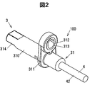
- FIG. 2 is a perspective view showing the sensor unit.
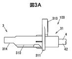
- FIG. 3A is a side view showing the sensor unit.
- FIG. 3B is a broken sectional view showing the housing in section in FIG. 3A.
- FIG. 4A is a top view showing the sensor unit.
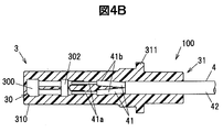
- FIG. 4B is a broken sectional view showing the housing in section in FIG. 4A.
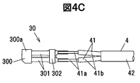
- FIG. 4C is a top view showing the magnetic sensor and the electric wire.
- FIG. 5A is an explanatory diagram showing a cable with a sensor according to a modification of the present invention.
- FIG. 5B is a cross-sectional view showing the cable of FIG. 5A.
- FIG. 1 is a sectional view showing a rotation detection device according to the present embodiment and a vehicle wheel bearing device having the rotation detection device.
- the wheel bearing device 10 includes an inner ring 11 as a rotating member having a cylindrical main body 110 and a flange portion 111 to which a wheel is attached, an outer ring 12 disposed on the outer peripheral side of the main body 110 of the inner ring 11, and an inner ring 11. Between the pair of raceway surfaces 11b and 11b formed on the outer peripheral surface 11a and the pair of raceway surfaces 12b and 12b formed on the inner peripheral surface 12a of the outer ring 12, and rolls on both raceway surfaces 11b and 12b. A plurality of spherical rolling elements 13 and a rotation detection device 1 that detects a rotation speed of the inner ring 11 relative to the outer ring 12 (that is, a wheel speed).
- a through hole is formed in the central portion of the main body 110 of the inner ring 11 along the rotation axis O, and a spline fitting portion 110a for connecting a drive shaft (not shown) is formed on the inner surface of the through hole. ing.
- the pair of raceway surfaces 11b and 11b of the inner ring 11 are formed in parallel to each other so as to extend in the circumferential direction.
- the flange portion 111 of the inner ring 11 protrudes radially outward from the main body 110 and is provided integrally with the main body 110.
- the flange portion 111 is formed with a plurality of through holes 111a into which bolts for attaching a wheel (not shown) are press-fitted.
- the outer ring 12 is formed in a cylindrical shape, and is fixed to a knuckle 9 connected to the vehicle body by a plurality of bolts 91 (only one is shown in FIG. 1).
- the knuckle 9 is an example of a fixing member that rotatably supports the inner ring 11.
- the pair of raceway surfaces 12b, 12b of the outer ring 12 are formed in parallel to each other so as to extend in the circumferential direction facing the pair of raceway surfaces 11b, 11b of the inner ring 11.
- a seal 14 is disposed between the outer ring 12 and the inner ring 11 at the end of the inner ring 11 on the flange 111 side.
- the knuckle 9 is formed with a holding hole 90 for holding the sensor unit 3 of the rotation detecting device 1 described below.
- the holding hole 90 has a circular cross section perpendicular to the central axis, and penetrates the knuckle 9 in the radial direction of the rotation axis O.
- FIG. 2 is a perspective view of the sensor unit.
- FIG. 3A is a side view showing the sensor portion
- FIG. 3B is a broken sectional view showing the housing in section.
- 4A is a top view showing the sensor portion
- FIG. 4B is a broken sectional view showing the housing in section
- FIG. 4C is a top view showing the magnetic sensor and the electric wire.
- the rotation detection device 1 is attached to an inner ring 11 as a rotating member, and has a plurality of magnetic poles (non-magnetic poles) along the circumferential direction around the rotation axis (rotation axis O) of the inner ring 11.
- the sensor is mounted on a magnetic encoder 2 as a detected member provided with a magnetic member 2 and a knuckle 9 as a fixed member that does not rotate with the rotation of the inner ring 11, and is disposed facing the magnetic encoder 2.
- Part 3
- the magnetic encoder 2 is formed in an annular shape having a thickness in a direction parallel to the rotation axis O.
- the magnetic encoder 2 is supported by a support member 112 fixed to the outer peripheral surface 11 a of the inner ring 11 and is attached so as to rotate integrally with the inner ring 11.
- the magnetic encoder 2 has an N magnetic pole and an S magnetic pole that are alternately arranged along the circumferential direction so as to face the sensor unit 3.
- the sensor unit 3 is provided at the end of the cable 4.
- the cable 4 with the sensor according to the present embodiment is provided with the sensor unit 3 at the end of the cable 4.
- the magnetic encoder 2 and the tip of the sensor unit 3 face each other in the axial direction parallel to the rotation axis O.
- the sensor unit 3 includes a plurality of magnetic sensors 30 and a housing unit 31 made of a resin mold that collectively covers the plurality of magnetic sensors 30. Yes.
- the sensor unit 3 includes two magnetic sensors 30.
- the cable 4 has a plurality of pairs (two pairs here) of electric wires 41 corresponding to the plurality of magnetic sensors 30.
- Each electric wire 41 is covered with a central conductor 41a made of a twisted conductor formed by twisting highly conductive strands such as copper, and an outer periphery of the central conductor 41a, and is made of an insulating resin such as crosslinked polyethylene. And a body 41b.
- the cable 4 further includes a sheath 42 that collectively covers two pairs (four) of electric wires 41.
- two pairs of electric wires 41 are exposed from the sheath 42, and at the end of the electric wire 41, the central conductor 41a is exposed from the insulator 41b.
- the center conductor 41a exposed from the insulator 41b is electrically connected to the connection terminal 301 of the corresponding magnetic sensor 30 by resistance welding.
- the magnetic sensor 30 includes a detection unit 300 and a pair of connection terminals 301 extending from the detection unit 300.
- the detection unit 300 includes a magnetic detection element (not shown) that detects a magnetic field from the magnetic encoder 2, a signal processing circuit (not shown) that processes a signal output from the magnetic detection element, a magnetic detection element, and a signal processing circuit. And a resin mold 300a as a cover for covering all of the above.
- the detection unit 300 is formed in a substantially rectangular plate shape in plan view (a shape in which one of four corners of a rectangle is chamfered).
- the detection axis (magnetic field detection direction) of the magnetic detection element is the vertical direction in FIG. 4A (the tangential direction of a circle with the rotation axis O as the center).
- connection terminals 301 extends from one long side (the long side not connected to the chamfered corner) of the detection unit 300 in a direction perpendicular to the long side. Are formed parallel to each other.
- both connection terminals 301 are formed in a band shape, and the center conductor 41a of the corresponding electric wire 41 is electrically connected to the tip (the end opposite to the detection unit 300). Yes.
- the pair of connection terminals 301 of one of the magnetic sensors 30 on the side close to the magnetic encoder 2 are linearly parallel to the same direction as the extending direction of the center conductor 41a. It extends in a shape.
- the pair of connection terminals 301 of the other magnetic sensor 30 on the side far from the magnetic encoder 2 is formed to be bent into a crank shape.
- the pair of connection terminals 301 of the other magnetic sensor 30 has a portion extending in parallel with the direction in which the central conductor 41a extends from the connection portion with the central conductor 41a, and is bent from the portion to one of the connection terminals 301. It has a portion extending in the direction of the magnetic sensor 30 (in the diagonally lower left direction in FIG. 3B), and further has a portion that is bent from the portion and extends in the same direction as the extending direction of the central conductor 41a.
- a capacitive element for suppressing noise is connected between the connection terminals 301 so as to cover the capacitive element and the connection terminal 301 connected to the capacitive element.
- a capacitive element protection unit 302 formed of a resin mold is provided.
- the capacitive element protection unit 302 provided in the other magnetic sensor 30 has a linear pair between the pair of connection terminals 301 of the one magnetic sensor 30 and the pair of connection terminals 301 of the other magnetic sensor 30.
- the space formed between the connection terminal 301 and the pair of crank-shaped connection terminals 301 is arranged while effectively utilizing.
- each detection unit 300 of a plurality (here, two) of magnetic sensors 30 is stacked in the facing direction of the sensor unit 3 and the magnetic encoder 2.
- Each detection unit 30 is stacked in a direction (in the present embodiment, a direction orthogonal) that intersects the lead-out direction in which the cable 4 is led out from the housing unit 31.
- the magnetic sensor 30 arranged farthest from the magnetic encoder 2 has higher sensitivity than the magnetic sensor 30 arranged closest to the magnetic encoder 2.
- the detection units 300 of both magnetic sensors 30 are stacked in the thickness direction. That is, in the present embodiment, the facing direction of the sensor unit 3 and the magnetic encoder 2 matches the thickness direction (stacking direction) of the detection unit 300. Note that the facing direction of the sensor unit 3 and the magnetic encoder 2 and the thickness direction (stacking direction) of the detection unit 300 do not have to be exactly the same, and may be slightly shifted. That is, “each detection unit 300 is stacked in the facing direction between the sensor unit 3 and the magnetic encoder 2” means that the facing direction between the sensor unit 3 and the magnetic encoder 2 and the stacking direction of the detection unit 300 are the same. A case where it is shifted by several degrees (for example, about ⁇ 10 °) is also included.
- the thickness direction (stacking direction) of the detection unit 300 is equal to the axial direction. I'm doing it. For example, when the magnetic encoder 2 and the tip of the sensor unit 3 are opposed to each other in the radial direction perpendicular to the rotation axis O, the thickness direction (stacking direction) of the detection unit 300 is set. It is better to match the radial direction.
- both detection units 300 are directly stacked. That is, the surface of one detection unit 300 and the surface of the other detection unit 300 are in contact with each other. As a result, it is possible to reduce the size as compared with the case where the two detection units 300 are arranged apart from each other, and it is easy to maintain the distance between the magnetic detection elements in both detection units 300 constant. The detection accuracy can be improved by minimizing the distance to the magnetic encoder 2 of the magnetic sensor 30 arranged further away.
- both detection units 300 are not bonded and fixed by an adhesive or the like, and both detection units 300 are held in the housing unit 31 in a stacked state.
- the two detection units 300 are stacked such that at least a part of both magnetic detection elements overlap in the facing direction (axial direction) between the sensor unit 3 and the magnetic encoder 2.
- the plurality of magnetic sensors 30 can be arranged in a compact manner as compared with the case where the sensor units 3 are arranged in the width direction perpendicular to the thickness direction. Even when a plurality of magnetic sensors 30 are used, the entire sensor unit 3 can be kept small.
- the thickness of the detection unit 300 is, for example, about 1 mm, but when the detection units 300 of both magnetic sensors 30 are arranged apart from each other for some reason, the distance (gap) between the sensor unit 3 and the magnetic encoder 2 is compared. If the target is large, the strength of the magnetic field detected by the magnetic sensor 30 disposed at a position distant from the magnetic encoder 2 may be reduced, and the detection accuracy may be reduced.
- the sensitivity of the magnetic sensor 30 arranged farthest from the magnetic encoder 2 is set higher than the sensitivity of the magnetic sensor 30 arranged closest to the magnetic encoder 2.
- the magnetic sensor 30 disposed on the side opposite to the magnetic encoder 2 has higher sensitivity than the magnetic sensor 30 disposed on the magnetic encoder 2 side. Will be used.
- high sensitivity means that a smaller magnetic field strength can be detected. That is, “high sensitivity” means that the minimum value of the detectable magnetic field intensity is smaller.
- a Hall IC is used as the magnetic sensor 30 arranged on the magnetic encoder 2 side, and a GMR (Giant Magneto Resistive) having higher sensitivity than the Hall IC is used as the magnetic sensor 30 arranged on the opposite side of the magnetic encoder 2. effect) A sensor was used.
- a Hall IC As the magnetic sensor 30 arrange
- a sensor may be used.
- the rotation speed (wheel speed) of the inner ring 11 relative to the outer ring 12 is further increased.
- a GMR sensor or an AMR sensor is used as the magnetic sensor 30 arranged on the magnetic encoder 2 side, and a GMR sensor is used as the magnetic sensor 30 arranged on the opposite side of the magnetic encoder 2.
- a TMR sensor having higher sensitivity than the AMR sensor may be used.
- a GMR sensor is used as the magnetic sensor 30 arranged on the magnetic encoder 2 side, and the sensitivity is higher than that of the GMR sensor arranged on the magnetic encoder 2 side as the magnetic sensor 30 arranged on the opposite side of the magnetic encoder 2. It is also possible to use the same type of magnetic sensor 30 with different sensitivities, such as using a high GMR sensor.
- the indirect air pressure detection device detects the occurrence of puncture or the like at any wheel by comparing the rotation speeds (wheel speeds) of the four wheels of the vehicle.
- the sensitivity of the magnetic sensors 30 other than the magnetic sensor 30 arranged closest to the magnetic encoder 2 is equal to or higher than the sensitivity of the magnetic sensor 30 arranged closer to the magnetic encoder 2 than the magnetic sensor 30.
- the Hall ICs having the same sensitivity are used as the two magnetic sensors 30 arranged closer to the magnetic encoder 2, and the two magnetic sensors 30 are arranged further apart from the magnetic encoder 2. It is also possible to use a GMR sensor having the same sensitivity as the magnetic sensor 30.
- the housing part 31 integrally forms a substantially cylindrical main body part 310 that covers the magnetic sensor 30 and the end of the cable 4 together, and a flange part 311 for fixing the sensor part 3 to the knuckle 9. It becomes.
- a bolt hole 312 for passing a bolt 92 (see FIG. 1) for fixing the sensor unit 3 to the knuckle 9 is formed in the flange portion 311, and the bolt hole 312 is formed on the inner peripheral surface of the bolt hole 312.
- a collar 313 made of metal for suppressing deformation of the flange portion 311 when the bolt is fixed is provided.
- a facing surface 314 that faces the magnetic encoder 2 is formed at the tip of the main body 310 of the housing 31 (the end opposite to the extension side of the cable 4).
- the sensor unit 3 is fixed to the knuckle 9 in a state in which the facing surface 314 is opposed to the magnetic encoder 2 (a state in which the facing surface 314 is opposed in the axial direction parallel to the rotation axis O).
- the housing part 31 for example, one made of PA (polyamide) 612, nylon 66 (nylon is a registered trademark), PBT (polybutylene terephthalate), or the like can be used.
- PA polyamide
- nylon 66 nylon is a registered trademark
- PBT polybutylene terephthalate
- PA612 mixed with a glass filler is used as the resin used for the housing portion 31.
- the cable 4 is obtained by collectively covering the two pairs of electric wires 41 with the sheath 42. It may be included.
- the cable 4a is composed of two pairs of twisted wires 43 formed by twisting a pair of wires 41, and a pair of power supplies having an outer diameter and a conductor cross-sectional area larger than those of the wires 41.
- a tape member 45 spirally wound around an assembly 44 formed by twisting the wire 7, the pair of twisted wires 43 and the power supply wire 7, and a sheath 42 covered on the outer periphery of the tape member 45. It is equipped with.
- a sensor unit 3 is provided at one end of each pair of twisted wires 43.
- a vehicle body side sensor connector 75 for connection to a wire group in a relay box provided on the vehicle body of the vehicle is attached to the other end of the pair of twisted wires 43.
- the power line 7 is composed of a power line for supplying a drive current to an electric motor (not shown) for an electric parking brake (hereinafter referred to as EPB) mounted on a vehicle wheel.
- EPB electric parking brake
- EPB means that when a parking brake operation switch is operated from an off state to an on state when the vehicle is stopped, a drive current is output to the electric motor for a predetermined time (for example, 1 second), thereby This is an electric braking device that is pressed against the disk rotor of the wheel and generates a braking force on the wheel. Further, in EPB, when the parking brake operation switch is operated from the on state to the off state, or when the accelerator pedal is depressed, the drive current is output to the electric motor, and the brake pad is connected to the disc rotor of the wheel. The brake force applied to the wheels is released by being separated. That is, the operating state of the EPB is maintained until the parking brake operation switch is turned off or the accelerator pedal is depressed after the parking brake operation switch is turned on.
- a predetermined time for example, 1 second
- the power supply line 7 includes a power supply line central conductor 71 and a power supply line insulator 72 that covers the outer periphery of the power supply line central conductor 71.
- the power line center conductor 71 is made of a stranded wire conductor obtained by twisting highly conductive strands such as copper, and the power line insulator 72 is made of an insulating resin such as crosslinked polyethylene.
- a wheel-side power connector 73a for connection to an electric motor for EPB is attached to one end of the pair of power lines 7, and a group of wires in the relay box is connected to the other end of the pair of power lines 7.
- a vehicle body side power connector 73b is attached for connection.
- the assembly 44 is configured by twisting both pairs of twisted wires 43 and a pair of power supply wires 7 together.
- the power supply line 7 is arranged between the paired twisted wires 43 in the circumferential direction.
- one twisted wire 43, one power wire 7, the other twisted wire 43, and the other power wire 7 are sequentially arranged in the clockwise direction.
- the straight cable 4a can be easily realized and a part in the longitudinal direction. In this case, it is possible to suppress a problem that a direction that is difficult to bend occurs, and to suppress a decrease in flexibility.
- EPB basically, a drive current is supplied to the electric motor when the vehicle is stopped.
- the rotation detection device 1 is used when the vehicle is traveling, and the rotation detection device 1 is not used when the drive current is supplied to the power line 7. Therefore, in the present embodiment, the shield conductor provided around the power supply line 7 and the twisted pair wire 43 is omitted.
- the shield conductor By omitting the shield conductor, the outer diameter of the cable 4a can be reduced as compared with the case where the shield conductor is provided, and the number of parts can be reduced to reduce the cost.
- the pair of twisted wires 43 that transmit electric signals when the vehicle is traveling are separated by a pair of power supply wires 7 that mainly supply a drive current to the electric motor after the vehicle stops. Therefore, even if the shield conductor provided around the twisted pair wire 43 is omitted, the crosstalk between the paired twisted wires 43 can be reduced.
- a plurality of thread-like (fiber-like) interventions extending in the longitudinal direction of the cable 4a may be arranged.
- the assembly 44 may be configured by twisting together this interposition, the pair of twisted wires 43 and the power supply wire 7 together.
- the cross-sectional shape when the tape member 45 is wound around the outer periphery of the assembly 44 can be made closer to a circular shape.
- a polypropylene yarn, a staple yarn (rayon staple fiber), an aramid fiber, a nylon fiber, or a fibrous material such as a fiber-based plastic, paper, or cotton yarn can be used.
- a tape member 45 is spirally wound around the assembly 44, and the tape member 45 contacts all the electric wires (the four electric wires 41 and the pair of power supply wires 7) covered by the tape member 45. ing.
- the tape member 45 is interposed between the assembly 44 and the sheath 42, and plays a role of reducing friction between the assembly 44 (the electric wire 41 and the power supply line 7) and the sheath 42 when bent. That is, by providing the tape member 45, the friction between the electric wire 41 and the power line 7 and the sheath 42 is reduced without using a lubricant such as talc powder, and the stress applied to the electric wire 41 and the power line 7 during bending is reduced. It becomes possible to reduce and improve bending resistance.
- the tape member 45 it is desirable to use a slippery material (with a small friction coefficient) with respect to the insulator 41 b of the electric wire 41 and the power line insulator 72 of the power line 7, for example, non-woven fabric, paper, Or what consists of resin (resin film etc.) can be used.
- the tape member 45 is spirally wound around the assembly 44 so that a part of the width direction (a direction perpendicular to the longitudinal direction and the thickness direction of the tape member 45) overlaps. The portion where the tape member 45 overlaps is not bonded with an adhesive or the like.
- the sensor unit 3 detects the magnetic field from the magnetic encoder 2 and the signal processing circuit that processes the signal output from the magnetic detection element.
- a plurality of magnetic sensors 30 having a plate-like detection unit 300 having a resin mold 300a that collectively covers the magnetic detection element and the signal processing circuit. They are stacked in the direction facing the encoder 2.
- the sensor part 3 can be reduced in size, for example, and the clearance gap between the sensor part 3 and the magnetic encoder 2 is used. Can be detected using a plurality of magnetic sensors 30 even when the stacking interval of the detectors 300 is large.
- the magnetic sensor 30 arranged farthest from the magnetic encoder 2 has higher sensitivity than the magnetic sensor 30 arranged closest to the magnetic encoder 2.
- both magnetic sensors 30 have sufficiently high sensitivity.
- the magnetic sensor 30 with high sensitivity is expensive, the cost of the rotation detection device 1 increases. According to the present embodiment, it is possible to realize a highly reliable rotation detection device 1 using a plurality of magnetic sensors 30 while suppressing costs.
- a plurality of magnetic sensors (30) each having a plate-like detection unit (300) having a cover (300a) that collectively covers the detection unit (300) includes the sensor unit (3). Laminated in the direction facing the detected member (2) Rotation detecting device (1).
- the magnetic sensor (30) arranged farthest from the detected member (2) is more than the magnetic sensor (30) arranged closest to the detected member (2).
- the sensor unit (3) includes the two magnetic sensors (30), and the magnetic sensor (30) disposed on the detected member (2) side includes a Hall IC, and The rotation detection device (1) according to [2], wherein the magnetic sensor (30) disposed on the opposite side of the detection member (2) is formed of a GMR sensor, an AMR sensor, or a TMR sensor.
- the sensor unit (3) includes the two magnetic sensors (30), and the magnetic sensor (30) disposed on the detected member (2) side includes a GMR sensor or an AMR sensor.
- a member to be detected (2) attached to the rotating member (11) and provided with a plurality of magnetic poles along a circumferential direction around the rotation axis of the rotating member (11), and the rotation A rotation detection device comprising: a sensor portion (3) that is attached to a fixed member (9) that does not rotate in accordance with the rotation of the member (11), and that is disposed to face the detected member (2).
- a sensor-equipped cable (100) used in (1) including a cable (4) and the sensor part (3) provided at an end of the cable (4), and the sensor part ( 3) collects the magnetic detection element for detecting the magnetic field from the detected member (2), the signal processing circuit for processing the signal output from the magnetic detection element, and the magnetic detection element and the signal processing circuit.
- a plurality of magnetic sensors (30) having a projecting part (300) are provided, and each of the detection parts (300) is stacked in a facing direction of the sensor part (3) and the detected member (2). Cable with sensor (100).
- the magnetic sensor (30) arranged farthest from the detected member (2) is more than the magnetic sensor (30) arranged closest to the detected member (2).
- the rotation detection device (1) detects a rotation speed of the rotating member (11) rotating together with a vehicle wheel, and the cable (4) is connected to the plurality of magnetic sensors (30).
- the sensor-equipped cable (100a) according to [5] or [6], comprising: a sheath (42) that collectively covers the power line (7).
- the present invention is not limited to this, and the present invention can be applied to, for example, a drive shaft sensor, a crank angle sensor, and the like. is there.
Landscapes
- Physics & Mathematics (AREA)
- General Physics & Mathematics (AREA)
- Engineering & Computer Science (AREA)
- General Engineering & Computer Science (AREA)
- Mechanical Engineering (AREA)
- Transportation (AREA)
- Transmission And Conversion Of Sensor Element Output (AREA)
- Rolling Contact Bearings (AREA)
Abstract
回転検出装置1は、回転部材としての内輪11に取り付けられており、内輪11の周方向に沿って複数の磁極が設けられている被検出部材としての磁気エンコーダ2と、内輪11の回転に伴って回転しない固定部材としてのナックル9に取り付けられており、磁気エンコーダ2と対向して配置されているセンサ部3と、を備え、センサ部3は、磁気検出素子と信号処理回路とを一括して樹脂モールド300aで覆った板状の検出部300を有している複数の磁気センサ30を備え、各検出部300は、センサ部3と磁気エンコーダ2との対向方向に積層されており、磁気エンコーダ2から最も離れて配置されている磁気センサ30は、磁気エンコーダ2に最も近接して配置されている磁気センサ30よりも感度が高い。
Description
本発明は、回転検出装置及びセンサ付きケーブルに関する。
車輪の軸受ユニットに用いられ、車輪と共に回転する回転部材の回転速度を検出する回転検出装置が知られている(例えば、特許文献1参照。)。
特許文献1では、回転部材に取り付けられ、回転部材の周方向に沿って複数の磁極を有する被検出部材と、回転部材を回転可能に支持する固定部材に取り付けられ、前記被検出部材の磁界を検出する検出素子を有する磁気センサと、を備えた回転検出装置が記載されている。
車輪の回転速度を測定する回転検出装置においては、磁気センサの故障等が生じても車輪の回転速度が検出できるように、あるいは、より精度よく車輪の回転速度が検出できるように、複数の磁気センサを用いたいという要求がある。
複数の磁気センサをセンサ部に搭載する場合、センサ部全体のサイズが大きくなってしまい、例えば、センサ部を保持する保持孔に挿入できなくなる、といった不具合が生じるおそれがある。そのため、複数の磁気センサを搭載した場合であっても、センサ部を小型に維持したいという要求があった。
本発明は、複数の磁気センサを備えつつもセンサ部を小型にすることが可能な回転検出装置及びセンサ付きケーブルを提供することを目的とする。
本発明の一態様に従う回転検出装置は、上記課題を解決することを目的として、回転部材に取り付けられており、前記回転部材の回転軸を中心とした周方向に沿って複数の磁極が設けられている被検出部材と、前記回転部材の回転に伴って回転しない固定部材に取り付けられており、前記被検出部材と対向して配置されているセンサ部と、を備え、前記センサ部は、前記被検出部材からの磁界を検出する前記磁気検出素子、前記磁気検出素子から出力された信号を処理する信号処理回路、及び前記磁気検出素子と前記信号処理回路とを一括して覆う覆い体を有する板状の検出部を有している複数の磁気センサを備え、前記各検出部は、前記センサ部と前記被検出部材との対向方向に積層されており、前記被検出部材から最も離れて配置されている前記磁気センサは、前記被検出部材に最も近接して配置されている前記磁気センサよりも感度が高い。
また、本発明の一態様に従うセンサ付きケーブルは、上記課題を解決することを目的として、回転部材に取り付けられており、前記回転部材の回転軸を中心とした周方向に沿って複数の磁極が設けられている被検出部材と、前記回転部材の回転に伴って回転しない固定部材に取り付けられており、前記被検出部材と対向して配置されているセンサ部と、を備えた回転検出装置に用いられるセンサ付きケーブルであって、ケーブルと、前記ケーブルの端部に設けられた前記センサ部と、を有し、前記センサ部は、前記被検出部材からの磁界を検出する前記磁気検出素子、前記磁気検出素子から出力された信号を処理する信号処理回路、及び前記磁気検出素子と前記信号処理回路とを一括して覆う樹脂モールドを有する板状の検出部を有している複数の磁気センサを備え、前記各検出部は、前記センサ部と前記被検出部材との対向方向に積層されている。
本発明の一態様に従い、複数の磁気センサを備えつつもセンサ部を小型にすることが可能な回転検出装置及びセンサ付きケーブルが提供される。
[実施の形態]
以下、本発明の実施の形態を添付図面にしたがって説明する。
以下、本発明の実施の形態を添付図面にしたがって説明する。
(車輪軸受装置10の構成)
図1は、本実施の形態に係る回転検出装置、及びこの回転検出装置を有する車両用の車輪軸受装置を示す断面図である。
図1は、本実施の形態に係る回転検出装置、及びこの回転検出装置を有する車両用の車輪軸受装置を示す断面図である。
車輪軸受装置10は、円筒状の本体部110、及び車輪が取り付けられるフランジ部111を有する回転部材としての内輪11と、内輪11の本体部110の外周側に配置された外輪12と、内輪11の外周面11aに形成された一対の軌道面11b,11b、及び外輪12の内周面12aに形成された一対の軌道面12b,12bの間に配置され、両軌道面11b,12bを転動する球状の複数の転動体13と、内輪11の外輪12に対する回転速度(すなわち車輪速)を検出する回転検出装置1とを備えている。
内輪11の本体部110の中心部には、その回転軸線Oに沿って貫通孔が形成され、この貫通孔の内面には、図示しないドライブシャフトを連結するためのスプライン嵌合部110aが形成されている。また、内輪11の一対の軌道面11b,11bは、周方向延びるように、互いに平行に形成されている。
内輪11のフランジ部111は、本体部110の径方向外側に突出して本体部110と一体に設けられている。フランジ部111には、図示しない車輪を取り付けるためのボルトが圧入される複数の貫通孔111aが形成されている。
外輪12は、円筒状に形成され、車体に連結されたナックル9に複数のボルト91(図1には1つのみ示す)によって固定されている。ナックル9は、内輪11を回転可能に支持する固定部材の一例である。外輪12の一対の軌道面12b,12bは、内輪11の一対の軌道面11b,11bに対向して周方向延びるように、互いに平行に形成されている。外輪12における内輪11のフランジ部111側の端部には、内輪11との間にシール14が配置されている。
ナックル9には、次に説明する回転検出装置1のセンサ部3を保持するための保持孔90が形成されている。保持孔90は、中心軸に直交する断面の形状が円形であり、ナックル9を回転軸線Oの径方向に貫通している。
(回転検出装置1の説明)
図2はセンサ部の斜視図である。図3Aはセンサ部を示す側面図であり、図3Bはそのハウジングを断面で示した破断面図である。図4Aはセンサ部を示す上面図であり、図4Bはそのハウジングを断面で示した破断面図、図4Cは磁気センサと電線を示す上面図である。
図2はセンサ部の斜視図である。図3Aはセンサ部を示す側面図であり、図3Bはそのハウジングを断面で示した破断面図である。図4Aはセンサ部を示す上面図であり、図4Bはそのハウジングを断面で示した破断面図、図4Cは磁気センサと電線を示す上面図である。
図1~4に示すように、回転検出装置1は、回転部材としての内輪11に取り付けられており、内輪11の回転軸(回転軸線O)を中心した周方向に沿って複数の磁極(不図示)が設けられている被検出部材としての磁気エンコーダ2と、内輪11の回転に伴って回転しない固定部材としてのナックル9に取り付けられており、磁気エンコーダ2と対向して配置されているセンサ部3と、を備えている。
磁気エンコーダ2は、回転軸線Oに平行な方向の厚みを有する環状に形成されている。この磁気エンコーダ2は、内輪11の外周面11aに固定された支持部材112に支持され、内輪11と一体回転するように取り付けられている。また、磁気エンコーダ2は、センサ部3に対向して周方向に沿って交互に配列されたN磁極とS磁極とを有している。
センサ部3は、ケーブル4の端部に設けられている。ケーブル4の端部にセンサ部3を設けたものが、本実施の形態に係るセンサ付きケーブル100である。本実施の形態では、磁気エンコーダ2とセンサ部3の先端部とが、回転軸線Oに平行な軸方向に対向している。
本実施の形態に係る回転検出装置1では、センサ部3は、複数の磁気センサ30と、複数の磁気センサ30を一括して被覆している樹脂モールドからなるハウジング部31と、を有している。ここでは、センサ部3が2つの磁気センサ30を有している場合について説明する。
ケーブル4は、複数の磁気センサ30に対応した複数対(ここでは2対)の電線41を有している。各電線41は、銅等の良導電性の素線を撚り合わせた撚線導体からなる中心導体41aと、中心導体41aの外周に被覆されており、架橋ポリエチレン等の絶縁性の樹脂からなる絶縁体41bと、を有している。また、ケーブル4は、2対(4本)の電線41を一括して覆うシース42をさらに有している。
ケーブル4の端部においては、シース42から2対の電線41が露出され、さらに電線41の端部において、絶縁体41bから中心導体41aが露出されている。絶縁体41bから露出された中心導体41aは、対応する磁気センサ30の接続端子301に、抵抗溶接により電気的に接続されている。
磁気センサ30は、検出部300と、検出部300から延出された一対の接続端子301と、を有している。
検出部300は、磁気エンコーダ2からの磁界を検出する磁気検出素子(不図示)と、磁気検出素子から出力された信号を処理する信号処理回路(不図示)と、磁気検出素子と信号処理回路とを一括して覆う覆い体としての樹脂モールド300aと、を有している。検出部300は、平面視で略長方形(長方形の4つの角部のうち1つが面取りされた形状)の板状に形成されている。磁気検出素子の検出軸(磁界の検出方向)は、図4Aにおける上下方向(回転軸線Oを中心とした円の接線方向)である。
一対の接続端子301は、検出部300の一方の長辺(面取りされた角部に接続されていない側の長辺)から当該長辺と垂直な方向に延出されており、両接続端子301は互いに平行に形成されている。本実施の形態では、両接続端子301は帯状に形成されており、その先端部(検出部300と反対側の端部)には、対応する電線41の中心導体41aが電気的に接続されている。
また、磁気エンコーダ2に近い側の一方の磁気センサ30(図3Bでいえば、下側の磁気センサ30)の一対の接続端子301は、中心導体41aの延出方向と同じ方向に平行に直線状に延びている。一方、磁気エンコーダ2から遠い側の他方の磁気センサ30(図3Bでいえば、上側の磁気センサ30)の一対の接続端子301は、クランク形状に折り曲げられて形成されている。詳しくは、他方の磁気センサ30の一対の接続端子301は、中心導体41aとの接続部から中心導体41aの延出方向と同じ方向に平行に延びる部分を有するとともに、当該部分から折れ曲がって一方の磁気センサ30方向(図3Bでいえば、左斜め下方向)に延びる部分を有し、さらに、当該部分から折れ曲がって中心導体41aの延出方向と同じ方向に平行に延びる部分を有する。
図示していないが、両接続端子301の間には、ノイズを抑制するための容量素子が接続されており、その容量素子と容量素子と接続されている部分の接続端子301とを覆うように、樹脂モールドにより形成された容量素子保護部302が設けられている。他方の磁気センサ30に設けられている容量素子保護部302は、一方の磁気センサ30の一対の接続端子301と、他方の磁気センサ30の一対の接続端子301との間に、直線状の一対の接続端子301とクランク形状の一対の接続端子301との間にできるスペースを有効利用しながら配置されている。
本実施の形態に係る回転検出装置1では、複数(ここでは2つ)の磁気センサ30の各検出部300は、センサ部3と磁気エンコーダ2との対向方向に積層されている。また、各検出部30は、ケーブル4がハウジング部31から導出される導出方向に対して交差する方向(本実施の形態では、直交する方向)に積層されている。また、本実施の形態では、磁気エンコーダ2から最も離れて配置されている磁気センサ30は、磁気エンコーダ2に最も近接して配置されている磁気センサ30よりも感度が高い。なお、ケーブル4を屈曲し当該ケーブル4の屈曲部ごと樹脂モールドしてL字型のハウジング部30を形成する場合には、各検出部30は、ケーブル4がハウジング部31から導出される導出方向と同方向に積層される。
両磁気センサ30の検出部300は、その厚さ方向に積層されている。つまり、本実施の形態では、センサ部3と磁気エンコーダ2との対向方向と、検出部300の厚さ方向(積層方向)とが一致している。なお、センサ部3と磁気エンコーダ2との対向方向と、検出部300の厚さ方向(積層方向)とは厳密に一致している必要はなく、多少ずれていてもよい。つまり、「各検出部300は、センサ部3と磁気エンコーダ2との対向方向に積層されており」とは、センサ部3と磁気エンコーダ2との対向方向と、検出部300の積層方向とが数度(例えば±10°程度)ずれている場合も含まれる。
本実施の形態では、磁気エンコーダ2とセンサ部3の先端部とが回転軸線Oに平行な軸方向に対向しているため、検出部300の厚さ方向(積層方向)が、軸方向と一致している。なお、これに限らず、例えば、磁気エンコーダ2とセンサ部3の先端部とを回転軸線Oに垂直な径方向に対向させている場合には、検出部300の厚さ方向(積層方向)を、径方向に一致させるとよい。
また、本実施の形態では、両検出部300が直接積層されている。つまり、一方の検出部300の表面と、他方の検出部300の表面とが接触している。これにより、両検出部300を離間して配置した場合と比較して小型化が可能になると共に、両検出部300における磁気検出素子間の距離を一定に維持し易くなり、また磁気エンコーダ2からより離れて配置される磁気センサ30の磁気エンコーダ2までの距離を最小として検出精度を向上することができる。なお、本実施の形態では、両検出部300は接着剤等によって接着固定されておらず、両検出部300は積層された状態でハウジング部31に保持されている。
また、両検出部300は、両磁気検出素子の少なくとも一部が、センサ部3と磁気エンコーダ2との対向方向(軸方向)に重なり合うように積層されていることが望ましい。
複数の磁気センサ30を用いることで、1つの磁気センサ30が故障しても他の磁気センサ30を用いて検出を続行することが可能になり、回転検出装置1の信頼性が向上する。
また、検出部300を積層(厚さ方向に積層)することにより、例えばセンサ部3を厚さ方向と垂直な幅方向に並べて配置した場合と比較して、複数の磁気センサ30をコンパクトに配置することが可能になり、複数の磁気センサ30を用いた場合であっても、センサ部3全体を小型に維持することが可能になる。
検出部300の厚さは例えば1mm程度であるが、何らかの理由で両磁気センサ30の検出部300同士を離間して配置した場合や、センサ部3と磁気エンコーダ2間の距離(ギャップ)が比較的大きい場合には、磁気エンコーダ2から離れた位置に配置される磁気センサ30で検出される磁界の強度が小さくなり、検出精度が低下してしまうことも考えられる。
そこで、本実施の形態では、磁気エンコーダ2から最も離れて配置されている磁気センサ30の感度を、磁気エンコーダ2に最も近接して配置されている磁気センサ30の感度よりも高くしている。本実施の形態にように2つの磁気センサ30を用いる場合、磁気エンコーダ2と反対側に配置された磁気センサ30としては、磁気エンコーダ2側に配置された磁気センサ30よりも感度が高いものが用いられることになる。
なお、ここでいう「感度が高い」とは、より小さい磁界の強度を検出可能であることを意味している。つまり、「感度が高い」とは、検出可能な磁界の強度の最小値がより小さいことを意味している。
本実施の形態では、磁気エンコーダ2側に配置された磁気センサ30としてホールICを用い、磁気エンコーダ2と反対側に配置された磁気センサ30として、ホールICよりも感度が高いGMR(Giant Magneto Resistive effect)センサを用いた。なお、磁気エンコーダ2側に配置された磁気センサ30としてホールICを用いる場合、磁気エンコーダ2と反対側に配置された磁気センサ30としては、AMR(Anisotropic Magneto Resistive)センサやTMR(Tunneling Magneto Resistive)センサを用いてもよい。
また、例えば、内輪11の外輪12に対する回転速度(車輪速)の検出結果を車体安定制御装置や間接式空気圧検出装置に使用する場合など、内輪11の外輪12に対する回転速度(車輪速)をより精度よく検出することが要求される場合には、磁気エンコーダ2側に配置された磁気センサ30としてGMRセンサまたはAMRセンサを用い、磁気エンコーダ2と反対側に配置された磁気センサ30として、GMRセンサやAMRセンサよりも感度が高いTMRセンサを用いてもよい。なお、例えば、磁気エンコーダ2側に配置された磁気センサ30としてGMRセンサを用い、磁気エンコーダ2と反対側に配置された磁気センサ30として、磁気エンコーダ2側に配置されたGMRセンサよりも感度が高いGMRセンサを用いる、といったように、感度の異なる同じ種類の磁気センサ30を用いることも可能である。なお、間接式空気圧検出装置とは、車両の4つの車輪の回転数(車輪速)を比較することで任意の車輪でのパンクの発生等を検出するものである。
なお、3つ以上の磁気センサ30を用いる場合、磁気エンコーダ2から離れるほど感度が高くなるようにするとよい。より詳細には、最も磁気エンコーダ2側に配置される磁気センサ30以外の磁気センサ30は、その感度が、当該磁気センサ30よりも磁気エンコーダ2側に配置されている磁気センサ30の感度以上であるとよい。つまり、例えば、4つの磁気センサ30を用いる場合、磁気エンコーダ2により近接して配置されている2つの磁気センサ30として同じ感度のホールICを用い、より磁気エンコーダ2と離れて配置されている2つ磁気センサ30として同じ感度のGMRセンサを用いる、といったことも可能である。
ハウジング部31は、磁気センサ30とケーブル4の端部とを一括して覆う略円柱状の本体部310と、センサ部3をナックル9に固定するためのフランジ部311と、を一体に形成してなる。フランジ部311には、センサ部3をナックル9に固定するボルト92(図1参照)を通すためのボルト穴312が形成されており、ボルト穴312には、当該ボルト穴312の内周面に沿うように、ボルト固定の際にフランジ部311の変形を抑制するための金属からなるカラー313が設けられている。
ハウジング部31の本体部310の先端部(ケーブル4の延出側と反対側の端部)には、磁気エンコーダ2と対向する対向面314が形成されている。センサ部3は、この対向面314を磁気エンコーダ2と対向させた状態(回転軸線Oに平行な軸方向に対向させた状態)で、ナックル9に固定されている。
ハウジング部31としては、例えばPA(ポリアミド)612や、ナイロン66(ナイロンは登録商標)、PBT(ポリブチレンテレフタレート)等からなるものを用いることができる。本実施の形態では、ハウジング部31に用いる樹脂として、PA612にガラスフィラーを混入させたものを用いた。
(センサ付きケーブル100の変形例)
上記実施の形態では、ケーブル4が、2対の電線41をシース42で一括して覆ったものであったが、これに限らず、ケーブル4は、センサ部3用の電線41以外の電線を含むものであってもよい。
上記実施の形態では、ケーブル4が、2対の電線41をシース42で一括して覆ったものであったが、これに限らず、ケーブル4は、センサ部3用の電線41以外の電線を含むものであってもよい。
図5A,図5Bに示すセンサ付きケーブル100aでは、ケーブル4aは、1対の電線41を撚り合わせてなる2つの対撚線43と、電線41よりも外径及び導体断面積が大きい一対の電源線7と、両対撚線43と電源線7とが撚り合わされてなる集合体44の周囲に螺旋状に巻き付けられているテープ部材45と、テープ部材45の外周に被覆されているシース42と、を備えている。
両対撚線43の一端部には、センサ部3が設けられている。両対撚線43の他端部には、車両の車体に設けられた中継ボックス内における電線群との接続のための車体側センサ用コネクタ75が取り付けられている。
本実施の形態では、電源線7は、車両の車輪に搭載された電動パーキングブレーキ(以下、EPB)用の電気モータ(不図示)に駆動電流を供給するための電源線からなる。
EPBとは、車両の停止時に、パーキングブレーキ作動スイッチがオフ状態からオン状態に操作されたとき、所定時間(例えば1秒間)にわたって電気モータに駆動電流を出力することにより、電気モータによりブレーキパッドを車輪のディスクロータに押し付けた状態とし、車輪に制動力を発生させる電動式の制動装置である。また、EPBでは、パーキングブレーキ作動スイッチがオン状態からオフ状態に操作されたとき、あるいは、アクセルペダルが踏込操作されたときに、電気モータに駆動電流を出力し、ブレーキパッドを車輪のディスクロータから離間させて、車輪への制動力を解除するように構成されている。つまり、EPBの作動状態は、パーキングブレーキ作動スイッチがオンされてから、パーキングブレーキ作動スイッチがオフされるかアクセルペダルが踏み込まれるまで維持される。
電源線7は、電源線用中心導体71と、電源線用中心導体71の外周に被覆されている電源線用絶縁体72と、を有している。電源線用中心導体71は、銅等の良導電性の素線を撚り合わせた撚線導体からなり、電源線用絶縁体72は、架橋ポリエチレン等の絶縁性の樹脂からなる。
一対の電源線7の一端部には、EPB用の電気モータとの接続のための車輪側電源コネクタ73aが取り付けられ、1対の電源線7の他端部には、中継ボックス内における電線群との接続のための車体側電源コネクタ73bが取り付けられている。
集合体44は、両対撚線43と、1対の電源線7とを撚り合わせて構成される。本実施の形態では、周方向において両対撚線43の間に電源線7が配置されている。図5Bの断面においては、時計回り方向に、一方の対撚線43、一方の電源線7、他方の対撚線43、他方の電源線7が順次配置されている。
なお、電源線7を周方向に隣り合うように配置した場合(両対撚線43を隣り合うように配置した場合)には、集合体44の重心が集合体44の中心位置から大きくずれてしまい、この状態で両対撚線43と電源線7とを撚り合わせて集合体44を構成すると、集合体44が全体的に捩れた状態となってしまう。そのため、直線状のケーブル4aを作製することが困難となり、また長手方向の一部において曲げにくい方向が発生するなどして、可撓性が低下してしまう問題も生じる。本実施の形態のように、周方向において対撚線43と電源線7が交互に配置される構成とすることで、直線状のケーブル4aを容易に実現可能となり、かつ、長手方向の一部において曲げにくい方向が発生するといった不具合を抑制して、可撓性の低下を抑制できる。
なお、EPBでは、基本的に車両の停止時に電気モータに駆動電流を供給する。これに対して、回転検出装置1は車両の走行時に使用されるものであり、電源線7に駆動電流が供給されているときに回転検出装置1が使用されることはない。そこで、本実施の形態では、電源線7や対撚線43の周囲に設けられるシールド導体を省略している。シールド導体を省略することで、シールド導体を設けた場合と比較してケーブル4aの外径を小さくすることができ、また部品点数を削減してコストを抑制することも可能になる。
また、本実施の形態では、主に車両の停車後に電気モータへ駆動電流を供給する一対の電源線7により、車両の走行時に電気信号を伝送する両対撚線43を離間させている。これにより、対撚線43の周囲に設けられるシールド導体を省略したとしても、両対撚線43間のクロストークを低減することが可能となる。
両対撚線43と電源線7とテープ部材45との間には、ケーブル4aの長手方向に延びる糸状(繊維状)の複数の介在が配置されていてもよい。この場合、この介在と両対撚線43と電源線7とを共に撚り合わせることにより、集合体44を構成するとよい。これにより、集合体44の外周にテープ部材45を巻き付けた際の断面形状をより円形状に近づけることができる。介在としては、ポリプロピレンヤーンや、スフ糸(レーヨンステープルファイバー)、アラミド繊維、ナイロン繊維、あるいは繊維系プラスチック等の繊維状体や、紙もしくは綿糸を用いることができる。
集合体44の周囲には、テープ部材45が螺旋状に巻き付けられており、テープ部材45は、テープ部材45が覆う全ての電線(4本の電線41及び1対の電源線7)に接触している。テープ部材45は、集合体44とシース42との間に介在し、屈曲時に集合体44(電線41及び電源線7)とシース42間の摩擦を低減する役割を果たす。すなわち、テープ部材45を設けることで、タルク粉体等の潤滑剤を用いることなく、電線41や電源線7とシース42間の摩擦を低減し、屈曲時に電線41や電源線7にかかるストレスを低減して、耐屈曲性を向上させることが可能になる。
テープ部材45としては、電線41の絶縁体41bや、電源線7の電源線用絶縁体72に対して、滑りやすいもの(摩擦係数が小さいもの)を用いることが望ましく、例えば、不織布や紙、あるいは樹脂(樹脂フィルム等)からなるものを用いることができる。テープ部材45は、その幅方向(テープ部材45の長手方向及び厚さ方向と垂直な方向)の一部が重なり合うように、螺旋状に集合体44に巻き付けられている。なお、テープ部材45が重なり合う部分は、接着剤等により接着されていない。
(実施の形態の作用及び効果)
以上説明したように、本実施の形態に係る回転検出装置1では、センサ部3は、磁気エンコーダ2からの磁界を検出する磁気検出素子、磁気検出素子から出力された信号を処理する信号処理回路、及び磁気検出素子と信号処理回路とを一括して覆う樹脂モールド300aを有する板状の検出部300を有している複数の磁気センサ30を備え、各検出部300は、センサ部3と磁気エンコーダ2との対向方向に積層されている。
以上説明したように、本実施の形態に係る回転検出装置1では、センサ部3は、磁気エンコーダ2からの磁界を検出する磁気検出素子、磁気検出素子から出力された信号を処理する信号処理回路、及び磁気検出素子と信号処理回路とを一括して覆う樹脂モールド300aを有する板状の検出部300を有している複数の磁気センサ30を備え、各検出部300は、センサ部3と磁気エンコーダ2との対向方向に積層されている。
これにより、冗長化あるいは検出精度の向上のために複数の磁気センサ30を用いた場合であってもセンサ部3を小型にすることができ、かつ、例えばセンサ部3と磁気エンコーダ2間の隙間が大きい場合や検出部300の積層間隔が大きい場合であっても、複数の磁気センサ30を用いた検出が可能になる。
また、本実施の形態では、磁気エンコーダ2から最も離れて配置されている磁気センサ30は、磁気エンコーダ2に最も近接して配置されている磁気センサ30よりも感度が高い。例えば、磁気センサ30を2つ用いる場合において、両方の磁気センサ30として十分に感度が高いものを用いることも考えられる。しかし、感度が高い磁気センサ30は高価であるため、回転検出装置1のコストが増大してしまう。本実施の形態によれば、コストを抑制しつつも、複数の磁気センサ30を用いた信頼性の高い回転検出装置1を実現可能である。
(実施の形態のまとめ)
次に、以上説明した実施の形態から把握される技術思想について、実施の形態における符号等を援用して記載する。ただし、以下の記載における各符号等は、特許請求の範囲における構成要素を実施の形態に具体的に示した部材等に限定するものではない。
次に、以上説明した実施の形態から把握される技術思想について、実施の形態における符号等を援用して記載する。ただし、以下の記載における各符号等は、特許請求の範囲における構成要素を実施の形態に具体的に示した部材等に限定するものではない。
[1]回転部材(11)に取り付けられており、前記回転部材(11)の回転軸を中心とした周方向に沿って複数の磁極が設けられている被検出部材(2)と、前記回転部材(11)の回転に伴って回転しない固定部材(9)に取り付けられており、前記被検出部材(2)と対向して配置されているセンサ部(3)と、を備え、前記センサ部(3)は、前記被検出部材(2)からの磁界を検出する磁気検出素子、前記磁気検出素子から出力された信号を処理する信号処理回路、及び前記磁気検出素子と前記信号処理回路とを一括して覆う覆い体(300a)を有する板状の検出部(300)を有している複数の磁気センサ(30)を備え、前記各検出部(300)は、前記センサ部(3)と前記被検出部材(2)との対向方向に積層されている、回転検出装置(1)。
[2]前記被検出部材(2)から最も離れて配置されている前記磁気センサ(30)は、前記被検出部材(2)に最も近接して配置されている前記磁気センサ(30)よりも感度が高い、[1]に記載の回転検出装置(1)。
[3]前記センサ部(3)は、2つの前記磁気センサ(30)を有し、前記被検出部材(2)側に配置された前記磁気センサ(30)が、ホールICからなり、前記被検出部材(2)と反対側に配置された前記磁気センサ(30)が、GMRセンサ、AMRセンサ、またはTMRセンサからなる、[2]に記載の回転検出装置(1)。
[4]前記センサ部(3)は、2つの前記磁気センサ(30)を有し、前記被検出部材(2)側に配置された前記磁気センサ(30)が、GMRセンサまたはAMRセンサからなり、前記被検出部材(2)と反対側に配置された前記磁気センサ(30)が、TMRセンサからなる、[2]に記載の回転検出装置(1)。
[5]回転部材(11)に取り付けられており、前記回転部材(11)の回転軸を中心とした周方向に沿って複数の磁極が設けられている被検出部材(2)と、前記回転部材(11)の回転に伴って回転しない固定部材(9)に取り付けられており、前記被検出部材(2)と対向して配置されているセンサ部(3)と、を備えた回転検出装置(1)に用いられるセンサ付きケーブル(100)であって、ケーブル(4)と、前記ケーブル(4)の端部に設けられた前記センサ部(3)と、を有し、前記センサ部(3)は、前記被検出部材(2)からの磁界を検出する磁気検出素子、前記磁気検出素子から出力された信号を処理する信号処理回路、及び前記磁気検出素子と前記信号処理回路とを一括して覆う覆い体(300a)を有する板状の検出部(300)を有している複数の磁気センサ(30)を備え、前記各検出部(300)は、前記センサ部(3)と前記被検出部材(2)との対向方向に積層されている、センサ付きケーブル(100)。
[6]前記被検出部材(2)から最も離れて配置されている前記磁気センサ(30)は、前記被検出部材(2)に最も近接して配置されている前記磁気センサ(30)よりも感度が高い、[5]に記載のセンサ付きケーブル(100)。
[7]前記回転検出装置(1)は、車両の車輪と共に回転する前記回転部材(11)の回転速度を検出するものであり、前記ケーブル(4)は、前記複数の磁気センサ(30)に対応した複数対の電線(41)と、前記車輪に搭載された前記電動パーキングブレーキ用の電気モータに駆動電流を供給するための電源線(7)と、前記複数対の電線(41)と前記電源線(7)とを一括して被覆しているシース(42)と、を備える、[5]または[6]に記載のセンサ付きケーブル(100a)。
以上、本発明の実施の形態を説明したが、上記に記載した実施の形態は特許請求の範囲に係る発明を限定するものではない。また、実施の形態の中で説明した特徴の組合せの全てが発明の課題を解決するための手段に必須であるとは限らない点に留意すべきである。
本発明は、その趣旨を逸脱しない範囲で適宜変形して実施することが可能である。
例えば、上記実施の形態では、回転検出装置1が車輪速を検出するものである場合を説明したが、これに限らず、例えば、ドライブシャフトセンサやクランク角センサ等にも本発明は適用可能である。
1…回転検出装置
2…磁気エンコーダ(被検出部材)
3…センサ部
30…磁気センサ
300…検出部
300a…樹脂モールド(覆い体)
301…接続端子
31…ハウジング部
4…ケーブル
9…ナックル(固定部材)
10…車輪軸受装置
11…内輪(回転部材)
12…外輪
13…転動体
100…センサ付きケーブル
2…磁気エンコーダ(被検出部材)
3…センサ部
30…磁気センサ
300…検出部
300a…樹脂モールド(覆い体)
301…接続端子
31…ハウジング部
4…ケーブル
9…ナックル(固定部材)
10…車輪軸受装置
11…内輪(回転部材)
12…外輪
13…転動体
100…センサ付きケーブル
Claims (7)
- 回転部材に取り付けられており、前記回転部材の回転軸を中心とした周方向に沿って複数の磁極が設けられている被検出部材と、
前記回転部材の回転に伴って回転しない固定部材に取り付けられており、前記被検出部材と対向して配置されているセンサ部と、を備え、
前記センサ部は、
前記被検出部材からの磁界を検出する磁気検出素子、前記磁気検出素子から出力された信号を処理する信号処理回路、及び前記磁気検出素子と前記信号処理回路とを一括して覆う覆い体を有する板状の検出部を有している複数の磁気センサを備え、
前記各検出部は、前記センサ部と前記被検出部材との対向方向に積層されている、
回転検出装置。 - 前記被検出部材から最も離れて配置されている前記磁気センサは、前記被検出部材に最も近接して配置されている前記磁気センサよりも感度が高い、
請求項1に記載の回転検出装置。 - 前記センサ部は、2つの前記磁気センサを有し、
前記被検出部材側に配置された前記磁気センサが、ホールICからなり、
前記被検出部材と反対側に配置された前記磁気センサが、GMRセンサ、AMRセンサ、またはTMRセンサからなる、
請求項2に記載の回転検出装置。 - 前記センサ部は、2つの前記磁気センサを有し、
前記被検出部材側に配置された前記磁気センサが、GMRセンサまたはAMRセンサからなり、
前記被検出部材と反対側に配置された前記磁気センサが、TMRセンサからなる、
請求項2に記載の回転検出装置。 - 回転部材に取り付けられており、前記回転部材の回転軸を中心とした周方向に沿って複数の磁極が設けられている被検出部材と、
前記回転部材の回転に伴って回転しない固定部材に取り付けられており、前記被検出部材と対向して配置されているセンサ部と、を備えた回転検出装置に用いられるセンサ付きケーブルであって、
ケーブルと、
前記ケーブルの端部に設けられた前記センサ部と、を有し、
前記センサ部は、
前記被検出部材からの磁界を検出する磁気検出素子、前記磁気検出素子から出力された信号を処理する信号処理回路、及び前記磁気検出素子と前記信号処理回路とを一括して覆う覆い体を有する板状の検出部を有している複数の磁気センサを備え、
前記各検出部は、前記センサ部と前記被検出部材との対向方向に積層されている、
センサ付きケーブル。 - 前記被検出部材から最も離れて配置されている前記磁気センサは、前記被検出部材に最も近接して配置されている前記磁気センサよりも感度が高い、
請求項5に記載のセンサ付きケーブル。 - 前記回転検出装置は、車両の車輪と共に回転する前記回転部材の回転速度を検出するものであり、
前記ケーブルは、
前記複数の磁気センサに対応した複数対の電線と、
前記車輪に搭載された前記電動パーキングブレーキ用の電気モータに駆動電流を供給するための電源線と、
前記複数対の電線と前記電源線とを一括して被覆しているシースと、を備える、
請求項5または6に記載のセンサ付きケーブル。
Priority Applications (7)
| Application Number | Priority Date | Filing Date | Title |
|---|---|---|---|
| CN202110059676.8A CN112881747B (zh) | 2016-06-23 | 2017-06-22 | 旋转检测装置及带传感器电缆 |
| CN201780018600.2A CN108780110B (zh) | 2016-06-23 | 2017-06-22 | 旋转检测装置及带传感器电缆 |
| US16/091,864 US10816360B2 (en) | 2016-06-23 | 2017-06-22 | Rotation detection device and cable with sensor |
| DE112017001253.8T DE112017001253B4 (de) | 2016-06-23 | 2017-06-22 | Drehungsdetektionsvorrichtung und Kabel mit Sensor |
| US17/032,447 US11346686B2 (en) | 2016-06-23 | 2020-09-25 | Rotation detection device and cable with sensor |
| US17/729,358 US11692850B2 (en) | 2016-06-23 | 2022-04-26 | Rotation detection device and cable with sensor |
| US18/200,270 US12078514B2 (en) | 2016-06-23 | 2023-05-22 | Rotation detection device and cable with sensor |
Applications Claiming Priority (2)
| Application Number | Priority Date | Filing Date | Title |
|---|---|---|---|
| JP2016-124582 | 2016-06-23 | ||
| JP2016124582A JP6759751B2 (ja) | 2016-06-23 | 2016-06-23 | 回転検出装置及びセンサ付きケーブル |
Related Child Applications (2)
| Application Number | Title | Priority Date | Filing Date |
|---|---|---|---|
| US16/091,864 A-371-Of-International US10816360B2 (en) | 2016-06-23 | 2017-06-22 | Rotation detection device and cable with sensor |
| US17/032,447 Continuation US11346686B2 (en) | 2016-06-23 | 2020-09-25 | Rotation detection device and cable with sensor |
Publications (1)
| Publication Number | Publication Date |
|---|---|
| WO2017222013A1 true WO2017222013A1 (ja) | 2017-12-28 |
Family
ID=60784155
Family Applications (1)
| Application Number | Title | Priority Date | Filing Date |
|---|---|---|---|
| PCT/JP2017/023030 Ceased WO2017222013A1 (ja) | 2016-06-23 | 2017-06-22 | 回転検出装置及びセンサ付きケーブル |
Country Status (5)
| Country | Link |
|---|---|
| US (4) | US10816360B2 (ja) |
| JP (1) | JP6759751B2 (ja) |
| CN (2) | CN108780110B (ja) |
| DE (1) | DE112017001253B4 (ja) |
| WO (1) | WO2017222013A1 (ja) |
Cited By (4)
| Publication number | Priority date | Publication date | Assignee | Title |
|---|---|---|---|---|
| EP3706946A1 (fr) * | 2017-11-10 | 2020-09-16 | Safran Transmission Systems | Procédé de fabrication de pièce tournante magnétisée, pièce tournante et système de mesure de rotation d'une pièce tournante |
| CN114019304A (zh) * | 2021-11-01 | 2022-02-08 | 国网江苏省电力有限公司常州供电分公司 | 一种基于电场和磁场变化的电缆终端缺陷检测装置 |
| US11300160B2 (en) * | 2019-11-25 | 2022-04-12 | Aktiebolaget Skf | Bearing with gliding target and associated sensor |
| US11371562B2 (en) | 2019-11-25 | 2022-06-28 | SKF Aerospace France S.A.S | Bearing with distance measuring system and associated groove |
Families Citing this family (21)
| Publication number | Priority date | Publication date | Assignee | Title |
|---|---|---|---|---|
| JP6631672B1 (ja) * | 2018-10-03 | 2020-01-15 | 住友電装株式会社 | 車輪速センサ |
| DE102018217580B4 (de) * | 2018-10-15 | 2023-07-06 | Continental Automotive Technologies GmbH | Kabelanordnung zum Anschluss eines Raddrehzahlsensors und einer elektrischen Parkbremse |
| JP7156043B2 (ja) * | 2019-01-10 | 2022-10-19 | 日立金属株式会社 | 回転速センサ |
| JP7192624B2 (ja) * | 2019-04-01 | 2022-12-20 | 日立金属株式会社 | 回転速センサ |
| JP7095643B2 (ja) * | 2019-04-01 | 2022-07-05 | 日立金属株式会社 | 回転速センサ |
| JP6748931B1 (ja) * | 2019-04-02 | 2020-09-02 | 日立金属株式会社 | 回転検出装置 |
| JP7293818B2 (ja) * | 2019-04-03 | 2023-06-20 | 株式会社プロテリアル | センサ装置、センサ付きケーブル及び複合ケーブル |
| KR102536986B1 (ko) * | 2019-04-23 | 2023-05-26 | 주식회사 일진글로벌 | 복수의 센싱부를 갖는 휠속도 센서 및 이를 구비하는 휠베어링 |
| GB201908291D0 (en) * | 2019-06-11 | 2019-07-24 | Bristol Maritime Robotics Ltd | Improvements in or relating to sensors |
| JP7742573B2 (ja) * | 2019-08-27 | 2025-09-22 | パナソニックIpマネジメント株式会社 | 位置検知回路、位置検知システム、位置検知方法及びプログラム |
| JP7228100B2 (ja) * | 2019-09-25 | 2023-02-24 | 株式会社プロテリアル | センサ装置、センサ付き多芯電線、複合ケーブル、及びセンサ付き多芯電線の製造方法 |
| JP7272298B2 (ja) * | 2020-02-28 | 2023-05-12 | 株式会社プロテリアル | センサ付きケーブル及び回転検出装置 |
| JP7272300B2 (ja) * | 2020-03-02 | 2023-05-12 | 株式会社プロテリアル | センサ付きケーブル及び回転検出装置 |
| JP7439677B2 (ja) * | 2020-07-23 | 2024-02-28 | 株式会社プロテリアル | 回転検出装置 |
| KR102914205B1 (ko) * | 2021-03-24 | 2026-01-20 | 현대모비스 주식회사 | 차량용 휠 센서장치 |
| JP7080370B1 (ja) | 2021-03-25 | 2022-06-03 | 三菱電機株式会社 | 磁気検出装置 |
| KR102989043B1 (ko) | 2021-04-22 | 2026-07-09 | 현대모비스 주식회사 | 차량용 휠 센서장치 |
| DE102021211300A1 (de) | 2021-10-07 | 2023-04-13 | Robert Bosch Gesellschaft mit beschränkter Haftung | Sensoreinheit und korrespondierende Sensoranordnung |
| DE102021211291A1 (de) | 2021-10-07 | 2023-04-13 | Robert Bosch Gesellschaft mit beschränkter Haftung | Sensoreinheit und korrespondierende Sensoranordnung |
| CN114113666A (zh) * | 2021-10-14 | 2022-03-01 | 人本股份有限公司 | 轮毂轴承双轮速传感器的多级磁性圈结构 |
| JP2024078865A (ja) * | 2022-11-30 | 2024-06-11 | 株式会社シマノ | 人力駆動車用の回転装置、および、人力駆動車用のハブアセンブリ |
Citations (8)
| Publication number | Priority date | Publication date | Assignee | Title |
|---|---|---|---|---|
| WO2007041465A1 (en) * | 2005-09-29 | 2007-04-12 | Timken Us Corporation | Redundant angle sensor |
| JP2009058291A (ja) * | 2007-08-30 | 2009-03-19 | Hitachi Ltd | 物理量変換センサ及びそれを用いたモータ制御システム |
| JP2011102769A (ja) * | 2009-11-11 | 2011-05-26 | Aisan Industry Co Ltd | 回転角検出装置の製造方法 |
| WO2013061503A1 (ja) * | 2011-10-27 | 2013-05-02 | タイコエレクトロニクスジャパン合同会社 | 検出センサの製造方法、検出センサ、トランスミッション |
| JP2013237428A (ja) * | 2012-04-20 | 2013-11-28 | Hitachi Cable Ltd | 複合ハーネス |
| US20140046625A1 (en) * | 2012-08-07 | 2014-02-13 | Micronas Gmbh | Method for determining an angle of rotation |
| JP2015536470A (ja) * | 2012-12-05 | 2015-12-21 | ローベルト ボッシュ ゲゼルシャフト ミット ベシュレンクテル ハフツング | 回転部材の少なくとも1つの回転特性を決定するためのセンサ装置 |
| JP2016109554A (ja) * | 2014-12-05 | 2016-06-20 | 株式会社ジェイテクト | 回転角検出装置 |
Family Cites Families (28)
| Publication number | Priority date | Publication date | Assignee | Title |
|---|---|---|---|---|
| FR2717266B1 (fr) | 1994-03-08 | 1996-04-19 | Roulements Soc Nouvelle | Dispositif de détection de la vitesse de rotation d'un palier de roulement. |
| JP2002340918A (ja) * | 2001-05-17 | 2002-11-27 | Ntn Corp | 回転数検出装置およびこれを具備する車輪用軸受 |
| US20040232906A1 (en) * | 2003-05-19 | 2004-11-25 | Taneyhill David J. | High temperature magnetoresistive sensor |
| DE10331580A1 (de) * | 2003-07-11 | 2005-01-27 | Robert Bosch Gmbh | Vorrichtung zur Detektion der Drehzahl und/oder der Position eines rotierenden Bauteils |
| US7135859B2 (en) * | 2004-04-06 | 2006-11-14 | Murugesan Sethu | Rotary and angular position sensing |
| JP4661236B2 (ja) * | 2005-01-28 | 2011-03-30 | アイシン精機株式会社 | 回転検出センサ |
| DE102005022596A1 (de) | 2005-05-17 | 2006-11-23 | Continental Teves Ag & Co. Ohg | Anordnung zur eigensicheren Raddrehzahlerfassung |
| DE102005060713B4 (de) | 2005-12-19 | 2019-01-24 | Austriamicrosystems Ag | Magnetfeldsensoranordnung und Verfahren zur berührungslosen Messung eines Magnetfeldes |
| JP4739963B2 (ja) * | 2006-01-18 | 2011-08-03 | アルプス電気株式会社 | 車載用gmr角度センサ |
| JP4273363B2 (ja) * | 2006-11-21 | 2009-06-03 | 日立金属株式会社 | 回転角度検出装置、回転機、及び回転角度検出法 |
| US8294457B2 (en) * | 2007-09-07 | 2012-10-23 | Joral Llc | Rotary magnetic encoder assembly, chip and method |
| DE102008003341B4 (de) * | 2008-01-07 | 2021-07-01 | Robert Bosch Gmbh | Sensorvorrichtung |
| DE102008028618B3 (de) * | 2008-06-18 | 2009-11-12 | Ecs Engineered Control Systems Ag | Elektromechanische Gebereinrichtung |
| JP5161010B2 (ja) * | 2008-09-11 | 2013-03-13 | Ntn株式会社 | 回転検出装置および回転検出装置付き軸受 |
| JP5263024B2 (ja) * | 2009-06-18 | 2013-08-14 | 株式会社日立製作所 | 回転角検出装置および回転速度検出装置 |
| JP5349157B2 (ja) * | 2009-06-19 | 2013-11-20 | Ntn株式会社 | 回転検出装置および回転検出装置付き軸受 |
| JP5671255B2 (ja) * | 2009-06-30 | 2015-02-18 | Ntn株式会社 | 自動車駆動用モータの回転角度検出装置および回転角度検出装置付き軸受 |
| DE102009048389B4 (de) * | 2009-10-06 | 2019-12-19 | Asm Automation Sensorik Messtechnik Gmbh | Anordnung zur Erfassung mehr als einer Umdrehung mitels Magneten als Positionsgeber |
| US8797024B2 (en) * | 2011-02-01 | 2014-08-05 | Infineon Technologies Ag | Sensor |
| JP2013047636A (ja) | 2011-08-29 | 2013-03-07 | Hitachi Cable Ltd | 回転検出装置及び車輪軸受装置 |
| CN202994815U (zh) * | 2012-12-03 | 2013-06-12 | 深圳市信亚科传感科技有限公司 | 齿轮测速判向传感器 |
| MX340713B (es) * | 2012-12-28 | 2016-07-20 | Sumitomo Wiring Systems | Sensor de velocidad de rueda y mazo de cables. |
| CN105408725B (zh) * | 2013-07-16 | 2017-11-10 | Ntn株式会社 | 磁性编码器装置以及旋转检测装置 |
| CN103528625A (zh) * | 2013-10-18 | 2014-01-22 | 无锡乐尔科技有限公司 | 一种齿轮传感器 |
| CN104121933B (zh) * | 2014-07-07 | 2017-01-18 | 林云 | 旋转编码器 |
| DE102015202333A1 (de) | 2015-02-10 | 2016-08-11 | Robert Bosch Gmbh | Sensorgehäuse für eine Radsensorvorrichtung, Radsensorvorrichtung und deren Anbindungskomponente |
| JP6601185B2 (ja) | 2015-11-26 | 2019-11-06 | 住友電装株式会社 | 車輪速センサ |
| US10315590B2 (en) * | 2016-06-14 | 2019-06-11 | Hitachi Metals, Ltd. | Cable and wire harness |
-
2016
- 2016-06-23 JP JP2016124582A patent/JP6759751B2/ja active Active
-
2017
- 2017-06-22 CN CN201780018600.2A patent/CN108780110B/zh active Active
- 2017-06-22 WO PCT/JP2017/023030 patent/WO2017222013A1/ja not_active Ceased
- 2017-06-22 US US16/091,864 patent/US10816360B2/en active Active
- 2017-06-22 DE DE112017001253.8T patent/DE112017001253B4/de active Active
- 2017-06-22 CN CN202110059676.8A patent/CN112881747B/zh active Active
-
2020
- 2020-09-25 US US17/032,447 patent/US11346686B2/en active Active
-
2022
- 2022-04-26 US US17/729,358 patent/US11692850B2/en active Active
-
2023
- 2023-05-22 US US18/200,270 patent/US12078514B2/en active Active
Patent Citations (8)
| Publication number | Priority date | Publication date | Assignee | Title |
|---|---|---|---|---|
| WO2007041465A1 (en) * | 2005-09-29 | 2007-04-12 | Timken Us Corporation | Redundant angle sensor |
| JP2009058291A (ja) * | 2007-08-30 | 2009-03-19 | Hitachi Ltd | 物理量変換センサ及びそれを用いたモータ制御システム |
| JP2011102769A (ja) * | 2009-11-11 | 2011-05-26 | Aisan Industry Co Ltd | 回転角検出装置の製造方法 |
| WO2013061503A1 (ja) * | 2011-10-27 | 2013-05-02 | タイコエレクトロニクスジャパン合同会社 | 検出センサの製造方法、検出センサ、トランスミッション |
| JP2013237428A (ja) * | 2012-04-20 | 2013-11-28 | Hitachi Cable Ltd | 複合ハーネス |
| US20140046625A1 (en) * | 2012-08-07 | 2014-02-13 | Micronas Gmbh | Method for determining an angle of rotation |
| JP2015536470A (ja) * | 2012-12-05 | 2015-12-21 | ローベルト ボッシュ ゲゼルシャフト ミット ベシュレンクテル ハフツング | 回転部材の少なくとも1つの回転特性を決定するためのセンサ装置 |
| JP2016109554A (ja) * | 2014-12-05 | 2016-06-20 | 株式会社ジェイテクト | 回転角検出装置 |
Cited By (4)
| Publication number | Priority date | Publication date | Assignee | Title |
|---|---|---|---|---|
| EP3706946A1 (fr) * | 2017-11-10 | 2020-09-16 | Safran Transmission Systems | Procédé de fabrication de pièce tournante magnétisée, pièce tournante et système de mesure de rotation d'une pièce tournante |
| US11300160B2 (en) * | 2019-11-25 | 2022-04-12 | Aktiebolaget Skf | Bearing with gliding target and associated sensor |
| US11371562B2 (en) | 2019-11-25 | 2022-06-28 | SKF Aerospace France S.A.S | Bearing with distance measuring system and associated groove |
| CN114019304A (zh) * | 2021-11-01 | 2022-02-08 | 国网江苏省电力有限公司常州供电分公司 | 一种基于电场和磁场变化的电缆终端缺陷检测装置 |
Also Published As
| Publication number | Publication date |
|---|---|
| US20190094044A1 (en) | 2019-03-28 |
| JP2017227560A (ja) | 2017-12-28 |
| CN108780110B (zh) | 2021-01-22 |
| JP6759751B2 (ja) | 2020-09-23 |
| CN108780110A (zh) | 2018-11-09 |
| US12078514B2 (en) | 2024-09-03 |
| CN112881747A (zh) | 2021-06-01 |
| US20210010826A1 (en) | 2021-01-14 |
| US20220252426A1 (en) | 2022-08-11 |
| US11692850B2 (en) | 2023-07-04 |
| CN112881747B (zh) | 2023-11-10 |
| US10816360B2 (en) | 2020-10-27 |
| DE112017001253B4 (de) | 2026-03-12 |
| US11346686B2 (en) | 2022-05-31 |
| US20230296410A1 (en) | 2023-09-21 |
| DE112017001253T5 (de) | 2018-11-29 |
Similar Documents
| Publication | Publication Date | Title |
|---|---|---|
| JP6759751B2 (ja) | 回転検出装置及びセンサ付きケーブル | |
| JP7028067B2 (ja) | 磁気検出センサ、回転検出センサ及びセンサ付きケーブル | |
| JP7310744B2 (ja) | 回転検出装置 | |
| US12270439B2 (en) | Wheel bearing provided with wheel speed sensor having plurality of sensing units | |
| CN116601462A (zh) | 感应的位置传感器、装置 | |
| WO2016092607A1 (ja) | 車載用検出装置 | |
| JP6757525B2 (ja) | 回転検出装置及びセンサ付きケーブル | |
| JP7414110B2 (ja) | センサ付きケーブル | |
| JP6941284B2 (ja) | 回転検出装置及びセンサ付きケーブル | |
| US12322531B2 (en) | Composite cable and composite harness | |
| JP7439677B2 (ja) | 回転検出装置 | |
| EP2072845B1 (en) | Rolling bearing unit having sensor | |
| JP7228100B2 (ja) | センサ装置、センサ付き多芯電線、複合ケーブル、及びセンサ付き多芯電線の製造方法 | |
| US12123750B2 (en) | Rotation detection device | |
| JP2025070580A (ja) | 回転検出装置 |
Legal Events
| Date | Code | Title | Description |
|---|---|---|---|
| WWE | Wipo information: entry into national phase |
Ref document number: 112017001253 Country of ref document: DE |
|
| 121 | Ep: the epo has been informed by wipo that ep was designated in this application |
Ref document number: 17815479 Country of ref document: EP Kind code of ref document: A1 |
|
| 122 | Ep: pct application non-entry in european phase |
Ref document number: 17815479 Country of ref document: EP Kind code of ref document: A1 |
|
| WWG | Wipo information: grant in national office |
Ref document number: 112017001253 Country of ref document: DE |