WO2017213009A1 - フィルムの切り抜き方法 - Google Patents
フィルムの切り抜き方法 Download PDFInfo
- Publication number
- WO2017213009A1 WO2017213009A1 PCT/JP2017/020377 JP2017020377W WO2017213009A1 WO 2017213009 A1 WO2017213009 A1 WO 2017213009A1 JP 2017020377 W JP2017020377 W JP 2017020377W WO 2017213009 A1 WO2017213009 A1 WO 2017213009A1
- Authority
- WO
- WIPO (PCT)
- Prior art keywords
- film
- polarizer
- laser light
- cutout
- light irradiation
- Prior art date
- Legal status (The legal status is an assumption and is not a legal conclusion. Google has not performed a legal analysis and makes no representation as to the accuracy of the status listed.)
- Ceased
Links
Images
Classifications
-
- B—PERFORMING OPERATIONS; TRANSPORTING
- B23—MACHINE TOOLS; METAL-WORKING NOT OTHERWISE PROVIDED FOR
- B23K—SOLDERING OR UNSOLDERING; WELDING; CLADDING OR PLATING BY SOLDERING OR WELDING; CUTTING BY APPLYING HEAT LOCALLY, e.g. FLAME CUTTING; WORKING BY LASER BEAM
- B23K26/00—Working by laser beam, e.g. welding, cutting or boring
- B23K26/36—Removing material
- B23K26/38—Removing material by boring or cutting
-
- B—PERFORMING OPERATIONS; TRANSPORTING
- B23—MACHINE TOOLS; METAL-WORKING NOT OTHERWISE PROVIDED FOR
- B23K—SOLDERING OR UNSOLDERING; WELDING; CLADDING OR PLATING BY SOLDERING OR WELDING; CUTTING BY APPLYING HEAT LOCALLY, e.g. FLAME CUTTING; WORKING BY LASER BEAM
- B23K26/00—Working by laser beam, e.g. welding, cutting or boring
- B23K26/36—Removing material
- B23K26/40—Removing material taking account of the properties of the material involved
-
- G—PHYSICS
- G02—OPTICS
- G02B—OPTICAL ELEMENTS, SYSTEMS OR APPARATUS
- G02B5/00—Optical elements other than lenses
- G02B5/30—Polarising elements
-
- B—PERFORMING OPERATIONS; TRANSPORTING
- B23—MACHINE TOOLS; METAL-WORKING NOT OTHERWISE PROVIDED FOR
- B23K—SOLDERING OR UNSOLDERING; WELDING; CLADDING OR PLATING BY SOLDERING OR WELDING; CUTTING BY APPLYING HEAT LOCALLY, e.g. FLAME CUTTING; WORKING BY LASER BEAM
- B23K2103/00—Materials to be soldered, welded or cut
- B23K2103/30—Organic material
- B23K2103/42—Plastics
Definitions
- the present invention relates to a film cutting method. More specifically, the present invention relates to a film cutting method using laser light.
- polarizing plates are used in image display devices and the like, but in recent years, with the diversification of uses of image display devices, the shapes of polarizing plates used in the image display devices are also diversified.
- a polarizing plate or the like that is cut into a predetermined shape and has a cut-out portion may be used.
- laser light irradiation is known as one of means for cutting out a film.
- a polarizing plate including a polarizer obtained through a stretching process there is a problem that cracks are likely to occur from the starting point and the ending point of laser light irradiation.
- the present invention has been made to solve the above-described conventional problems, and a main object of the present invention is to provide a method of cutting out a film with a laser beam while preventing cracking of the film.
- the film cutting method of the present invention includes cutting a film containing a polarizer by laser light irradiation, and forming a cut-out portion having a predetermined shape on the film, and tangent to the cut-out portion at a cutting start point by the laser light irradiation.
- the angle between A or the side B of the cutout including the start point and the absorption axis of the polarizer is 0 ° to 85 ° or 95 ° to 180 °.
- an angle formed between the tangent line A or the side B and the absorption axis of the polarizer is 0 ° to 60 ° or 120 ° to 180 °.
- the tangent A or side B and the absorption axis of the polarizer are parallel.
- the film can be cut out by laser light while preventing cracking of the film by setting the cut-out starting point by laser light irradiation to a specific position.
- (A) And (b) is a figure explaining the cutting method of the film by one Embodiment of this invention. It is a figure explaining the cutting method of the film by another embodiment of this invention.
- the film cutting method of the present invention includes cutting a film containing a polarizer by laser light irradiation and forming a cutout portion having a predetermined shape on the film.
- the film containing a polarizer may be a polarizer alone or a film containing a polarizer (preferably one polarizer) and other layers. Examples of the other layers include a protective layer for protecting the polarizer and a layer composed of any appropriate optical film.
- a polarizing plate is used as a film including a polarizer.
- the polarizing plate may include a polarizer and a protective layer disposed on at least one side of the polarizer.
- the surface protective film or the separator is detachably laminated on the polarizing plate via any appropriate pressure-sensitive adhesive.
- the “surface protective film” is a film that temporarily protects the polarizing plate, and is different from the protective layer (layer that protects the polarizer) provided in the polarizing plate.
- the polarizer is typically a swelling treatment, a stretching treatment, a dyeing treatment with a dichroic substance (eg, iodine, an organic dye, etc.), a crosslinking treatment, a washing treatment, It can be obtained by performing various treatments such as a drying treatment.
- a polarizer obtained through a stretching treatment has a characteristic that cracks are likely to occur, but according to the present invention, a film can be cut out while preventing cracks.
- the thickness of the film containing the polarizer is not particularly limited, and an appropriate thickness can be adopted depending on the purpose, and is, for example, 20 ⁇ m to 200 ⁇ m.
- the thickness of the polarizer is also not particularly limited, and an appropriate thickness can be adopted depending on the purpose.
- the thickness of the polarizer is typically about 1 ⁇ m to 80 ⁇ m, preferably 3 ⁇ m to 40 ⁇ m.
- the size of the film including the polarizer is not particularly limited, and may be an appropriate size according to the purpose.
- the film including the polarizer has a rectangular shape or a square shape including a side parallel to the absorption axis of the polarizer, and the length of the side parallel to the absorption axis of the polarizer is from 10 mm to 400 mm, and the length of the other side is 10 mm to 500 mm.
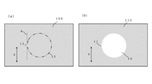
- FIG. 1 (a) and 1 (b) are diagrams illustrating a film cutting method according to an embodiment of the present invention.
- FIG. 1 (a) shows a film 100 including a polarizer at the time of starting cutting by laser light irradiation, that is, at the time of irradiating the cutting start point 11 with laser light.
- FIG. 1B shows a film after the cutting by laser light irradiation, that is, a film 110 having a cutout portion 10.
- the film 100 including the polarizer is obtained by irradiating the cutting start point 11 with a laser beam and then continuously irradiating the outer shell 12 of the portion to be cut out. Cut out, a substantially circular cutout 10 is formed in the film.
- the angle formed by the tangent A of the clipping portion at the clipping start point 11 by laser light irradiation and the absorption axis X of the polarizer is 0 ° to 85 ° or 95 ° to 180 °, preferably 0 ° to 60 ° or 120 ° to 180 °, more preferably 0 ° to 45 ° or 135 ° to 180 °, and particularly preferably Is 0 ° to 30 ° or 150 ° to 180 °.
- the tangent line A and the absorption axis X are parallel.
- parallel includes a case where they are substantially parallel, and specifically includes a case where an angle formed by two directions is 0 ° to 5 °. Further, when an angle is referred to in the present specification, the angle includes an angle in both a clockwise direction and a counterclockwise direction unless otherwise specified.
- the diameter can be set to any appropriate length depending on the use of the film.
- the diameter is, for example, 2 mm to 100 mm.
- a substantially circular cutout having a diameter of 2 mm to 50 mm (preferably 2 mm to 10 mm) can be formed while preventing cracks.
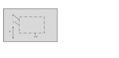
- FIG. 2 is a diagram for explaining a film cutting method according to another embodiment of the present invention.
- FIG. 2 shows a film including a polarizer at the time of starting cutting by laser light irradiation, that is, at the time of irradiating laser light to the cutting start point 11 ′.
- a film including a polarizer is obtained by first irradiating the cut-out starting point 11 ′ with laser light and then continuously irradiating the outline 12 ′ of the portion to be cut out. And a substantially rectangular cut-out portion is formed on the film. As illustrated in FIG.
- the angle formed between the side B including the cutout start point 11 ′ and the absorption axis X of the polarizer is 0 ° to 85 ° or 95 ° to 180 °, preferably 0 ° to 60 ° or 120 ° to 180 °, more preferably 0 ° to 45 ° or 135 ° to 180 °, particularly preferably 0 ° to 30 ° or It is 150 ° to 180 °.
- the side B and the absorption axis X are parallel.
- the short side is preferably 2 mm to 100 mm, more preferably 2 mm to 50 mm, still more preferably 2 mm to 30 mm, and particularly preferably 2 mm to 10 mm. is there.
- the long side is preferably 5 mm to 400 mm, more preferably 5 mm to 200 mm, still more preferably 5 mm to 120 mm, and particularly preferably 5 mm to 40 mm.
- the shape of the cutout portion is not limited to the shape shown in FIGS. Examples of the shape of the cutout portion include a substantially square shape and a substantially elliptical shape in addition to a substantially circular shape and a substantially rectangular shape. Further, the shape of the cutout portion may be a shape formed by appropriately combining a straight line and a curve, or a shape composed of a plurality of curves having different curvatures. When the outline of the cutout portion has a vertex and / or a connection point between a straight line and a curve, it is preferable not to use the vertex and the connection point as a cutout start point.
- the area ratio of the cutout portion is, for example, 10% to 50% with respect to the area of the film including the polarizer (the film before the cutout).
- the film can be cut out by laser light while preventing cracking of the film containing the polarizer.
- a cutout portion having a predetermined shape is formed by laser light
- laser light irradiation is started from the cutout start point, and after the cutout portion is formed, the laser light returns to the cutout start point. That is, the starting point and the ending point of laser light irradiation are the same part. Therefore, at the cutout start point which is the starting point and the end point of laser light irradiation, the cutout portion has a small but convex portion (a convex portion protruding to the film side having the cutout portion) as shown in FIG.
- cracking of the film can be prevented by setting the cut-out starting point, that is, the convex portion that can be a trigger for the crack, to the specific position with reference to the absorption axis of the polarizer.
- the film cut out by the method of the present invention has sufficient durability against severe temperature changes (for example, a heat cycle of ⁇ 40 ° C. to 85 ° C.), and does not easily crack.
- the laser beam preferably includes light having a wavelength of 200 nm to 11000 nm.
- any appropriate laser can be adopted as the laser used for laser light irradiation.
- any suitable laser can be employed.
- gas lasers such as CO 2 laser and excimer laser; solid-state lasers such as YAG laser; semiconductor lasers and the like.
- any appropriate conditions can be adopted depending on the film material, the film thickness, and the like.
- Example 1 Laser light was irradiated, and a circular cutout (diameter 20 mm) was cut out from a 72 mm square polarizer. The angle formed between the tangent line of the cutout at the cutout start point and the absorption axis of the polarizer was set to 0 °. The distance between each side of the polarizer and the center of the cutout was 30 mm.
- the laser light irradiation conditions were as follows. Wavelength: 9.4 ⁇ m Pulse width: 8 ⁇ s Output: 10V Frequency: 12.5kHz Processing speed: 400mm / sec
- Example 2 The polarizer was cut out in the same manner as in Example 1 except that the angle formed between the tangent line of the cutout portion at the cutout start point and the absorption axis of the polarizer was set to 30 °.
- Example 3 The polarizer was cut out in the same manner as in Example 1 except that the angle formed between the tangent line of the cutout portion at the cutout start point and the absorption axis of the polarizer was set to 45 °.
- Example 4 The polarizer was cut out in the same manner as in Example 1 except that the angle between the tangent line of the cutout starting point and the absorption axis of the polarizer was 60 °.
- Example 1 The polarizer was cut out in the same manner as in Example 1 except that the angle formed by the tangent line of the cutout portion at the cutout start point and the absorption axis of the polarizer was 90 °.
- the film cutting method of the present invention is suitably used when manufacturing an optical film such as a polarizer plate.
Landscapes
- Physics & Mathematics (AREA)
- Engineering & Computer Science (AREA)
- Optics & Photonics (AREA)
- Plasma & Fusion (AREA)
- Mechanical Engineering (AREA)
- General Physics & Mathematics (AREA)
- Polarising Elements (AREA)
- Laser Beam Processing (AREA)
Priority Applications (2)
| Application Number | Priority Date | Filing Date | Title |
|---|---|---|---|
| KR1020187035530A KR102328501B1 (ko) | 2016-06-10 | 2017-06-01 | 필름의 오려내기 방법 |
| CN201780035504.9A CN109313303B (zh) | 2016-06-10 | 2017-06-01 | 膜的裁切方法 |
Applications Claiming Priority (2)
| Application Number | Priority Date | Filing Date | Title |
|---|---|---|---|
| JP2016116147A JP6754621B2 (ja) | 2016-06-10 | 2016-06-10 | フィルムの切り抜き方法 |
| JP2016-116147 | 2016-06-10 |
Publications (1)
| Publication Number | Publication Date |
|---|---|
| WO2017213009A1 true WO2017213009A1 (ja) | 2017-12-14 |
Family
ID=60578611
Family Applications (1)
| Application Number | Title | Priority Date | Filing Date |
|---|---|---|---|
| PCT/JP2017/020377 Ceased WO2017213009A1 (ja) | 2016-06-10 | 2017-06-01 | フィルムの切り抜き方法 |
Country Status (5)
| Country | Link |
|---|---|
| JP (1) | JP6754621B2 (enExample) |
| KR (1) | KR102328501B1 (enExample) |
| CN (1) | CN109313303B (enExample) |
| TW (1) | TWI757301B (enExample) |
| WO (1) | WO2017213009A1 (enExample) |
Cited By (1)
| Publication number | Priority date | Publication date | Assignee | Title |
|---|---|---|---|---|
| WO2020162116A1 (ja) * | 2019-02-08 | 2020-08-13 | 日東電工株式会社 | 光学フィルムの製造方法 |
Citations (3)
| Publication number | Priority date | Publication date | Assignee | Title |
|---|---|---|---|---|
| JP2005189530A (ja) * | 2003-12-25 | 2005-07-14 | Nitto Denko Corp | 積層型偏光板およびその製造方法 |
| JP2009294649A (ja) * | 2008-05-07 | 2009-12-17 | Nitto Denko Corp | 偏光板、およびその製造方法 |
| JP2014182274A (ja) * | 2013-03-19 | 2014-09-29 | Fujifilm Corp | 偏光板、液晶表示装置、および液晶表示装置の製造方法。 |
Family Cites Families (17)
| Publication number | Priority date | Publication date | Assignee | Title |
|---|---|---|---|---|
| JPH06269967A (ja) * | 1993-03-25 | 1994-09-27 | Fanuc Ltd | レーザ加工方法及びその装置 |
| JP2005326831A (ja) | 2004-04-13 | 2005-11-24 | Nitto Denko Corp | 光学部材、その製造方法、およびそれを用いた画像表示装置 |
| JP4732790B2 (ja) * | 2005-04-28 | 2011-07-27 | 日本合成化学工業株式会社 | ポリビニルアルコール系フィルムの製造方法、ポリビニルアルコール系フィルムおよび偏光膜、偏光板 |
| JP2007319888A (ja) * | 2006-05-31 | 2007-12-13 | Sharp Corp | 被加工脆性部材のレーザー溶断方法 |
| JP4808106B2 (ja) * | 2006-08-23 | 2011-11-02 | 日東電工株式会社 | 光学フィルムの切断方法 |
| CN101755226A (zh) * | 2007-07-06 | 2010-06-23 | 日东电工株式会社 | 偏振光板 |
| JP2010017990A (ja) * | 2008-07-14 | 2010-01-28 | Seiko Epson Corp | 基板分割方法 |
| US8584490B2 (en) * | 2011-02-18 | 2013-11-19 | Corning Incorporated | Laser cutting method |
| JP5824218B2 (ja) * | 2011-02-24 | 2015-11-25 | 伊藤光学工業株式会社 | 防眩光学要素 |
| JP5821155B2 (ja) * | 2012-12-18 | 2015-11-24 | 住友化学株式会社 | 光学表示デバイスの生産方法及び光学表示デバイスの生産システム |
| JP2014191051A (ja) * | 2013-03-26 | 2014-10-06 | Nitto Denko Corp | 偏光子のレーザー加工方法 |
| JP6127707B2 (ja) * | 2013-05-16 | 2017-05-17 | 住友化学株式会社 | 光学表示デバイスの生産システム及び生産方法 |
| JP6227279B2 (ja) * | 2013-05-17 | 2017-11-08 | 住友化学株式会社 | 光学部材貼合体の製造装置及び製造方法 |
| JP2015108663A (ja) * | 2013-12-03 | 2015-06-11 | 住友化学株式会社 | 光学部材貼合体の製造装置 |
| KR20160015160A (ko) * | 2014-07-30 | 2016-02-12 | 스미또모 가가꾸 가부시키가이샤 | 방현 필름 |
| US20160033699A1 (en) * | 2014-08-04 | 2016-02-04 | Nitto Denko Corporation | Polarizing plate |
| KR101817388B1 (ko) * | 2014-09-30 | 2018-01-10 | 주식회사 엘지화학 | 편광판의 절단 방법 및 이를 이용하여 절단된 편광판 |
-
2016
- 2016-06-10 JP JP2016116147A patent/JP6754621B2/ja active Active
-
2017
- 2017-06-01 KR KR1020187035530A patent/KR102328501B1/ko active Active
- 2017-06-01 WO PCT/JP2017/020377 patent/WO2017213009A1/ja not_active Ceased
- 2017-06-01 CN CN201780035504.9A patent/CN109313303B/zh active Active
- 2017-06-08 TW TW106119003A patent/TWI757301B/zh active
Patent Citations (3)
| Publication number | Priority date | Publication date | Assignee | Title |
|---|---|---|---|---|
| JP2005189530A (ja) * | 2003-12-25 | 2005-07-14 | Nitto Denko Corp | 積層型偏光板およびその製造方法 |
| JP2009294649A (ja) * | 2008-05-07 | 2009-12-17 | Nitto Denko Corp | 偏光板、およびその製造方法 |
| JP2014182274A (ja) * | 2013-03-19 | 2014-09-29 | Fujifilm Corp | 偏光板、液晶表示装置、および液晶表示装置の製造方法。 |
Cited By (3)
| Publication number | Priority date | Publication date | Assignee | Title |
|---|---|---|---|---|
| WO2020162116A1 (ja) * | 2019-02-08 | 2020-08-13 | 日東電工株式会社 | 光学フィルムの製造方法 |
| JPWO2020162116A1 (ja) * | 2019-02-08 | 2021-12-09 | 日東電工株式会社 | 光学フィルムの製造方法 |
| JP7534963B2 (ja) | 2019-02-08 | 2024-08-15 | 日東電工株式会社 | 光学フィルムの製造方法 |
Also Published As
| Publication number | Publication date |
|---|---|
| JP2017219800A (ja) | 2017-12-14 |
| CN109313303B (zh) | 2021-04-20 |
| JP6754621B2 (ja) | 2020-09-16 |
| TWI757301B (zh) | 2022-03-11 |
| CN109313303A (zh) | 2019-02-05 |
| KR102328501B1 (ko) | 2021-11-18 |
| TW201801841A (zh) | 2018-01-16 |
| KR20190015290A (ko) | 2019-02-13 |
Similar Documents
| Publication | Publication Date | Title |
|---|---|---|
| CN105229500B (zh) | 局部具有去偏光区域的偏光板及其制备方法 | |
| KR102025065B1 (ko) | 편광자, 편광판, 및 화상 표시 장치 | |
| KR102662805B1 (ko) | 장척상의 편광자, 장척상의 편광판 및 화상 표시 장치 | |
| JP6422033B2 (ja) | レーザビーム焦線を用いたシート状基板のレーザベースの機械加工方法及び装置 | |
| JP6219781B2 (ja) | 偏光フィルム、偏光板及び液晶パネル | |
| JP6420747B2 (ja) | 偏光子、偏光板および偏光子の製造方法 | |
| KR102025066B1 (ko) | 편광자, 편광판, 및 화상 표시 장치 | |
| JP2020064313A (ja) | 偏光板 | |
| WO2019079417A3 (en) | Methods for laser processing transparent workpieces using pulsed laser beam focal lines and chemical etching solutions | |
| WO2017099017A1 (ja) | 偏光フィルムの製造方法 | |
| TWI726001B (zh) | 偏光元件、偏光板及偏光元件之製造方法 | |
| WO2017213009A1 (ja) | フィルムの切り抜き方法 | |
| KR102735839B1 (ko) | 편광판 및 그 제조 방법 | |
| KR102534054B1 (ko) | 편광자 및 그의 제조 방법 | |
| WO2016167060A1 (ja) | 偏光子、偏光板および偏光子の製造方法 | |
| US10295727B2 (en) | Display device and method for manufacturing display panel | |
| JP2017219800A5 (enExample) | ||
| KR20150053012A (ko) | 비금속재료 절단 방법 | |
| Oyoshi | MT Spence's Light the Sea |
Legal Events
| Date | Code | Title | Description |
|---|---|---|---|
| 121 | Ep: the epo has been informed by wipo that ep was designated in this application |
Ref document number: 17810187 Country of ref document: EP Kind code of ref document: A1 |
|
| ENP | Entry into the national phase |
Ref document number: 20187035530 Country of ref document: KR Kind code of ref document: A |
|
| NENP | Non-entry into the national phase |
Ref country code: DE |
|
| 122 | Ep: pct application non-entry in european phase |
Ref document number: 17810187 Country of ref document: EP Kind code of ref document: A1 |