WO2017208956A1 - 液体材料吐出装置、その塗布装置および塗布方法 - Google Patents
液体材料吐出装置、その塗布装置および塗布方法 Download PDFInfo
- Publication number
- WO2017208956A1 WO2017208956A1 PCT/JP2017/019503 JP2017019503W WO2017208956A1 WO 2017208956 A1 WO2017208956 A1 WO 2017208956A1 JP 2017019503 W JP2017019503 W JP 2017019503W WO 2017208956 A1 WO2017208956 A1 WO 2017208956A1
- Authority
- WO
- WIPO (PCT)
- Prior art keywords
- valve rod
- liquid material
- rod
- actuator
- discharge device
- Prior art date
Links
- 239000011344 liquid material Substances 0.000 title claims abstract description 95
- 238000000034 method Methods 0.000 title abstract description 12
- 238000004891 communication Methods 0.000 claims abstract description 44
- 230000001133 acceleration Effects 0.000 claims abstract description 34
- 238000003860 storage Methods 0.000 claims abstract description 22
- 238000001514 detection method Methods 0.000 claims description 47
- 230000007246 mechanism Effects 0.000 claims description 40
- 238000000576 coating method Methods 0.000 claims description 30
- 230000033001 locomotion Effects 0.000 claims description 26
- 239000011248 coating agent Substances 0.000 claims description 24
- 230000006835 compression Effects 0.000 claims description 5
- 238000007906 compression Methods 0.000 claims description 5
- 230000006837 decompression Effects 0.000 claims description 4
- 238000007599 discharging Methods 0.000 claims description 4
- 230000015572 biosynthetic process Effects 0.000 abstract 2
- 239000007788 liquid Substances 0.000 description 40
- 239000007789 gas Substances 0.000 description 34
- 238000003780 insertion Methods 0.000 description 28
- 230000037431 insertion Effects 0.000 description 28
- 230000005540 biological transmission Effects 0.000 description 9
- 230000002093 peripheral effect Effects 0.000 description 8
- 230000001174 ascending effect Effects 0.000 description 6
- 238000006073 displacement reaction Methods 0.000 description 6
- 238000012423 maintenance Methods 0.000 description 5
- 239000011347 resin Substances 0.000 description 5
- 229920005989 resin Polymers 0.000 description 5
- 238000005192 partition Methods 0.000 description 4
- 230000000630 rising effect Effects 0.000 description 4
- CURLTUGMZLYLDI-UHFFFAOYSA-N Carbon dioxide Chemical compound O=C=O CURLTUGMZLYLDI-UHFFFAOYSA-N 0.000 description 2
- 230000009471 action Effects 0.000 description 2
- 230000002493 climbing effect Effects 0.000 description 2
- 230000007423 decrease Effects 0.000 description 2
- 238000010586 diagram Methods 0.000 description 2
- 239000000428 dust Substances 0.000 description 2
- 239000000835 fiber Substances 0.000 description 2
- 230000010355 oscillation Effects 0.000 description 2
- 238000003825 pressing Methods 0.000 description 2
- 239000000758 substrate Substances 0.000 description 2
- IJGRMHOSHXDMSA-UHFFFAOYSA-N Atomic nitrogen Chemical compound N#N IJGRMHOSHXDMSA-UHFFFAOYSA-N 0.000 description 1
- 230000002411 adverse Effects 0.000 description 1
- 230000000903 blocking effect Effects 0.000 description 1
- 229910002092 carbon dioxide Inorganic materials 0.000 description 1
- 239000001569 carbon dioxide Substances 0.000 description 1
- 230000008859 change Effects 0.000 description 1
- 238000004140 cleaning Methods 0.000 description 1
- 238000007872 degassing Methods 0.000 description 1
- 229910001873 dinitrogen Inorganic materials 0.000 description 1
- 230000000694 effects Effects 0.000 description 1
- 238000002474 experimental method Methods 0.000 description 1
- 230000007774 longterm Effects 0.000 description 1
- 239000000463 material Substances 0.000 description 1
- 230000003287 optical effect Effects 0.000 description 1
- 230000000704 physical effect Effects 0.000 description 1
- 238000004382 potting Methods 0.000 description 1
- 230000008569 process Effects 0.000 description 1
- 230000004044 response Effects 0.000 description 1
- 230000004043 responsiveness Effects 0.000 description 1
- 239000004065 semiconductor Substances 0.000 description 1
- 238000001771 vacuum deposition Methods 0.000 description 1
Images


Classifications
-
- B—PERFORMING OPERATIONS; TRANSPORTING
- B05—SPRAYING OR ATOMISING IN GENERAL; APPLYING FLUENT MATERIALS TO SURFACES, IN GENERAL
- B05C—APPARATUS FOR APPLYING FLUENT MATERIALS TO SURFACES, IN GENERAL
- B05C5/00—Apparatus in which liquid or other fluent material is projected, poured or allowed to flow on to the surface of the work
- B05C5/02—Apparatus in which liquid or other fluent material is projected, poured or allowed to flow on to the surface of the work the liquid or other fluent material being discharged through an outlet orifice by pressure, e.g. from an outlet device in contact or almost in contact, with the work
- B05C5/0225—Apparatus in which liquid or other fluent material is projected, poured or allowed to flow on to the surface of the work the liquid or other fluent material being discharged through an outlet orifice by pressure, e.g. from an outlet device in contact or almost in contact, with the work characterised by flow controlling means, e.g. valves, located proximate the outlet
-
- B—PERFORMING OPERATIONS; TRANSPORTING
- B05—SPRAYING OR ATOMISING IN GENERAL; APPLYING FLUENT MATERIALS TO SURFACES, IN GENERAL
- B05C—APPARATUS FOR APPLYING FLUENT MATERIALS TO SURFACES, IN GENERAL
- B05C11/00—Component parts, details or accessories not specifically provided for in groups B05C1/00 - B05C9/00
- B05C11/10—Storage, supply or control of liquid or other fluent material; Recovery of excess liquid or other fluent material
- B05C11/1002—Means for controlling supply, i.e. flow or pressure, of liquid or other fluent material to the applying apparatus, e.g. valves
- B05C11/1026—Valves
-
- B—PERFORMING OPERATIONS; TRANSPORTING
- B05—SPRAYING OR ATOMISING IN GENERAL; APPLYING FLUENT MATERIALS TO SURFACES, IN GENERAL
- B05C—APPARATUS FOR APPLYING FLUENT MATERIALS TO SURFACES, IN GENERAL
- B05C11/00—Component parts, details or accessories not specifically provided for in groups B05C1/00 - B05C9/00
- B05C11/10—Storage, supply or control of liquid or other fluent material; Recovery of excess liquid or other fluent material
- B05C11/1002—Means for controlling supply, i.e. flow or pressure, of liquid or other fluent material to the applying apparatus, e.g. valves
- B05C11/1034—Means for controlling supply, i.e. flow or pressure, of liquid or other fluent material to the applying apparatus, e.g. valves specially designed for conducting intermittent application of small quantities, e.g. drops, of coating material
-
- B—PERFORMING OPERATIONS; TRANSPORTING
- B05—SPRAYING OR ATOMISING IN GENERAL; APPLYING FLUENT MATERIALS TO SURFACES, IN GENERAL
- B05C—APPARATUS FOR APPLYING FLUENT MATERIALS TO SURFACES, IN GENERAL
- B05C11/00—Component parts, details or accessories not specifically provided for in groups B05C1/00 - B05C9/00
- B05C11/10—Storage, supply or control of liquid or other fluent material; Recovery of excess liquid or other fluent material
- B05C11/1047—Apparatus or installations for supplying liquid or other fluent material comprising a buffer container or an accumulator between the supply source and the applicator
-
- B—PERFORMING OPERATIONS; TRANSPORTING
- B05—SPRAYING OR ATOMISING IN GENERAL; APPLYING FLUENT MATERIALS TO SURFACES, IN GENERAL
- B05C—APPARATUS FOR APPLYING FLUENT MATERIALS TO SURFACES, IN GENERAL
- B05C5/00—Apparatus in which liquid or other fluent material is projected, poured or allowed to flow on to the surface of the work
- B05C5/02—Apparatus in which liquid or other fluent material is projected, poured or allowed to flow on to the surface of the work the liquid or other fluent material being discharged through an outlet orifice by pressure, e.g. from an outlet device in contact or almost in contact, with the work
- B05C5/0225—Apparatus in which liquid or other fluent material is projected, poured or allowed to flow on to the surface of the work the liquid or other fluent material being discharged through an outlet orifice by pressure, e.g. from an outlet device in contact or almost in contact, with the work characterised by flow controlling means, e.g. valves, located proximate the outlet
- B05C5/0237—Fluid actuated valves
-
- B—PERFORMING OPERATIONS; TRANSPORTING
- B05—SPRAYING OR ATOMISING IN GENERAL; APPLYING FLUENT MATERIALS TO SURFACES, IN GENERAL
- B05C—APPARATUS FOR APPLYING FLUENT MATERIALS TO SURFACES, IN GENERAL
- B05C5/00—Apparatus in which liquid or other fluent material is projected, poured or allowed to flow on to the surface of the work
-
- B—PERFORMING OPERATIONS; TRANSPORTING
- B05—SPRAYING OR ATOMISING IN GENERAL; APPLYING FLUENT MATERIALS TO SURFACES, IN GENERAL
- B05D—PROCESSES FOR APPLYING FLUENT MATERIALS TO SURFACES, IN GENERAL
- B05D1/00—Processes for applying liquids or other fluent materials
- B05D1/26—Processes for applying liquids or other fluent materials performed by applying the liquid or other fluent material from an outlet device in contact with, or almost in contact with, the surface
-
- F—MECHANICAL ENGINEERING; LIGHTING; HEATING; WEAPONS; BLASTING
- F16—ENGINEERING ELEMENTS AND UNITS; GENERAL MEASURES FOR PRODUCING AND MAINTAINING EFFECTIVE FUNCTIONING OF MACHINES OR INSTALLATIONS; THERMAL INSULATION IN GENERAL
- F16K—VALVES; TAPS; COCKS; ACTUATING-FLOATS; DEVICES FOR VENTING OR AERATING
- F16K1/00—Lift valves or globe valves, i.e. cut-off apparatus with closure members having at least a component of their opening and closing motion perpendicular to the closing faces
- F16K1/32—Details
- F16K1/34—Cutting-off parts, e.g. valve members, seats
- F16K1/42—Valve seats
Definitions
- the present invention relates to an apparatus and a method for discharging a liquid material under a negative pressure environment.
- the “negative pressure environment” in this specification includes a vacuum environment.
- the most common method of degassing is to put the container (syringe) used for the actual work in which the liquid material is stored into another sealed container as it is before performing the work, and evacuate the sealed container. In this way, the liquid material is deaerated.
- a coating apparatus that degass the liquid material by setting the space where the coating is performed as a sealed space and evacuating the interior.
- Patent Document 1 includes a storage and discharge unit that stores a liquid material and discharges the liquid material from a discharge port.
- the storage and discharge unit and the application target are The coating apparatus includes at least a coating space that surrounds and an exhaust system that places the coating space in a negative pressure state, and discharges the liquid material from the storage and discharge unit to the coating target with the coating space in a negative pressure state.
- Patent Document 2 is a vacuum coating apparatus in which an article to be coated for supplying a liquid resin is placed in a vacuum chamber, and a liquid resin is supplied under a vacuum from a dispenser for supplying the liquid resin to a predetermined position of the article to be coated.
- the vacuum chamber for accommodating the article to be coated is constituted by a first container part for accommodating and supporting the article to be coated, and a second container part for mounting the nozzle of the dispenser,
- the second container part is relatively movable in the XY plane without breaking the hermetic state of the vacuum chamber, and at least one of the first and second container parts is moved in the XY plane;
- This is a coating apparatus in which an XY drive unit that can change the relative planar position between the article to be coated and the nozzle is installed outside the vacuum chamber.
- a dispensing device When a dispensing device is disposed in the negative pressure space to perform a coating operation, in a dispensing device including a valve rod (plunger) that reciprocates, the liquid pressure near the tip of the rod decreases due to the upward movement of the valve rod, There was a problem that bubbles were generated. When bubbles are generated in the vicinity of the tip of the valve rod, problems such as the disturbance of the drawing line due to the bubbles and the scattering of the liquid material at the time of discharge occur.
- an object of the present invention is to provide a liquid material ejection apparatus and method that can suppress the generation of bubbles due to the lifting operation of the rod in a negative pressure environment.
- Another object of the present invention is to provide a liquid material discharge apparatus and method that solves the problem of leakage of liquid material that is caused by insufficient closing of the valve rod tip due to wear of the valve rod tip or valve seat.
- a liquid material discharge device includes a storage container that stores a liquid material, a compressed gas supply source that pressurizes the storage container, a nozzle having a discharge flow path, a valve rod that reciprocates, and a valve.
- An actuator that drives the rod, a valve seat having a communication hole that communicates with the discharge flow path, and a discharge control device that controls the actuator to open and close the communication hole at the tip of the valve rod are used in a negative pressure space.
- a liquid material discharge device that is, the discharge control device, by controlling the range of acceleration time a u to 2 ⁇ 300 [ms "of ascent of the valve rod by the actuator, with an increase of the valve rod It is characterized by preventing the generation of bubbles.
- the discharge controller may be characterized in that for controlling the target speed V 1 of the ascent of the valve rod in the range of 0.2 ⁇ 30 [mm / s] by the actuator.
- the discharge controller may be the acceleration time A d during the descent of the valve rod by the actuator as a feature to be controlled in the range of 2 ⁇ 300 [ms ", in this case, the discharge controller may also be characterized by setting the acceleration time a d during acceleration time a u and falling at the time of rise of the valve rod in the same by the actuator.
- the actuator may be a motor that can control the advance position of the valve rod by the discharge control apparatus.
- the actuator may be a stepping motor, a servo, or the like.
- One drive selected from a motor and a linear motor may be used as a drive source, and a position detection mechanism for detecting that the tip of the valve rod is in a position to close the valve seat is provided. May be a feature.
- a liquid material discharge device includes a storage container for storing a liquid material, a compressed gas supply source for pressurizing the storage container, a nozzle having a discharge flow path, a valve rod that reciprocates, and a valve.
- a liquid material discharge device comprising: an actuator for driving a rod; a valve seat having a communication hole communicating with a discharge flow path; and a discharge control device for controlling the actuator to open and close the communication hole at the tip of the valve rod. And a position detection mechanism for detecting that the tip of the valve rod is in a position to close the valve seat.
- the actuator may be a motor that can control the advance position of the valve rod by the ejection control device.
- the actuator One motor selected from a stepping motor, a servo motor, and a linear motor may be used as a drive source.
- the position detection mechanism detects a slide member connected to the actuator, a slider connected to the slide member, and a slide member being in a predetermined position.
- a mechanism a rod interlocking member that is connected to the valve rod and is disposed so as to be separable from the slide member, and an elastic member that applies an urging force that abuts the rod interlocking member and the slide member so as to be separable.
- the slide member moves away from the rod interlocking member and moves downward when a force to further advance the valve rod is applied by the actuator.
- the sensor mechanism detects the movement of the slide member, the tip of the valve rod is moved to the valve shaft.
- the rod interlocking member is connected to the slider, and the elastic member is a tension coil spring that connects the rod interlocking member and the slide member.
- the elastic member has an initial tension Pi equivalent to a force capable of moving the rod interlocking member and the slide member when the valve rod and the valve seat are not in contact with each other. This may be a feature.
- the slide member has a top surface having a first through hole through which the valve rod is inserted, and a bottom surface having a second through hole through which the valve rod is inserted.
- the rod interlocking member and the elastic member are disposed between the top surface and the bottom surface of the slide member, and the elastic member separates the rod interlocking member from the top surface or the bottom surface of the slide member.
- the valve rod is inserted, and a fixing member for fixing the rod interlocking member is provided, and the elastic member is a compression coil spring through which the valve rod is inserted.
- the elastic member may move the valve rod, the rod interlocking member, and the fixing member. It may be characterized by having a force equivalent to repulsion Pii required.
- the valve rod In the liquid material discharge device, the valve rod is inserted, a first guide member that guides the linear movement of the valve rod, and the valve rod is inserted, and the valve rod is linearly moved below the first guide member.
- a member may be provided.
- the coating apparatus of the present invention includes the liquid material discharge device, a work table on which a work is installed, a relative drive device that relatively moves the liquid material discharge device and the work table, the liquid material discharge device, A cover that constitutes a negative pressure space in which the work table and the relative driving device are arranged, a pressure reducing device that makes negative pressure in the cover, and a drive control device that controls the relative driving device.
- the decompression device may be a vacuum pump.
- the coating method of the present invention is a coating method using the above-described coating device, wherein the workpiece and the liquid material discharge device are moved relative to each other while the inside of the cover is set to a negative pressure by the decompression device. A liquid material is applied to the substrate.
- the inside of the cover may be substantially vacuum.
- the present invention it is possible to prevent problems such as disorder of the drawing line and scattering of the liquid material during ejection by suppressing the generation of bubbles due to the upward movement of the valve rod. Further, since the liquid material is pumped with compressed gas and opened and closed with a valve rod, the response is good and stable discharge can be performed at high speed (high flow rate). Furthermore, in the present invention having the position detection mechanism, even if the valve rod tip or the valve seat is worn, the valve rod tip can be reliably closed.
- FIG. 2 is an AA arrow view in FIG. 1.
- FIG. 3 is a view taken along arrow BB in FIG. 1. It is explanatory drawing explaining operation
- FIG. 10 is a CC arrow view in FIG. 9. It is explanatory drawing explaining operation
- (a) is a front view and (b) is a DD arrow view in (a).
- the discharge device 1 discharges the liquid material by opening the communication hole 7 of the valve seat 6 by the upward movement of the valve rod 21 and stops the discharge by closing the communication hole 7 of the valve rod 21 by the downward movement.
- This type of discharge device is used by being mounted on the coating device 101 in a negative pressure space.
- the discharge device 1 can prevent the generation of bubbles by adjusting the speed and acceleration of the valve rod 21 by controlling the operation of the electric actuator 28 by the discharge control device 33.
- a position detection mechanism 34 for detecting a position where the valve rod 21 and the valve seat 6 are in contact with each other is provided, so that even if the valve rod 21 or the valve seat 6 is worn, the communication hole 7 of the valve seat 6 is surely provided. It is possible to close it.
- the structure of the discharge apparatus 1 is demonstrated first, and then the operation
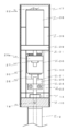
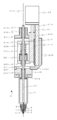
- FIG. 1 is a partial cross-sectional view of a discharge device 1 according to an embodiment of the present invention.
- 2 is a view taken along the line AA in FIG. 1
- FIG. 3 is a view taken along the line BB in FIG.
- the actuator 28 side may be referred to as “upper” and the nozzle 3 side may be referred to as “lower”.
- 1 may be referred to as “front view”, and the viewpoints in FIGS. 2 and 3 may be referred to as “side view”.
- the discharge device 1 includes a storage container (syringe) 2, a nozzle 3, a nozzle attachment member 5, a valve seat 6, a main body lower member 10, and a position detection mechanism 34.
- the storage container 2 used in the first embodiment is a general resin syringe having a flange 9 at the upper end and an inner cylinder 8 at the lower end.
- a valve rod 21 is inserted into the storage container 2, and the inner space of the inner cylinder 8 constitutes a rod tip portion insertion hole.
- a nozzle mounting member 5, a valve seat 6 and a nozzle 3 are mounted on the inner cylinder 8.
- the nozzle 3 is a tubular member, and the internal space forms the discharge flow path 4.
- the nozzle 2 is screwed into the lower end of the syringe 2 so that the syringe 2 and the discharge flow path 4 of the nozzle 3 are communicated with each other via the valve seat 6.
- the nozzle attachment member 5 is a cylindrical member, and a through hole into which the nozzle 3 is inserted is provided on the bottom surface.
- the valve seat 6 is mounted in a concave portion of the nozzle mounting member 5 and is fixed so as to be sandwiched between the nozzle mounting member 5 and the inner cylinder 8 at the lower end of the syringe 2.
- the valve seat 6 is located at the end of the syringe 2 and has a communication hole 7 that communicates the syringe 2 and the discharge flow path 4 of the nozzle 3.
- the main body lower member 10 is a plate-like member disposed at the lower end of the head cover 47 in which the actuator 28 and the upper and lower slide blocks (37, 38) are accommodated.
- a bowl-shaped rod support member 11 is provided and holds the flange portion 9 at the upper end of the syringe 2.
- a cylindrical insertion portion 12 having a diameter substantially the same as the two inner diameters of the syringe is provided on the lower surface of the lower body member 10 and is fitted into the syringe 2.
- a seal member B ⁇ b> 16 is installed on the outer periphery of the insertion portion 12 to prevent leakage of compressed gas.
- a through hole 13 into which the valve rod 21 is inserted is provided in the vertical direction at the center of the main body lower member 10 and the insertion portion 12.
- annular seal member A15 that prevents leakage of compressed gas is installed, and the valve rod 21 is inserted. Since the inner diameter of the through hole 13 is larger than that of the valve rod 21, the outer peripheral surface of the valve rod 21 is in contact only with the seal member A 15 and is not in contact with the inner peripheral surface of the through hole 13.
- a seal presser 17 for fixing the seal member A15 is provided at the upper end of the through hole 13.
- the upper end of the through hole 13 forms a protruding portion 14 that protrudes upward from the main body lower member 10 by the amount of the seal member A15 and the seal presser 17, but is not limited thereto.
- the seal member A15 may be provided so that the upper surface of the main body lower member 10 is flat.
- a compressed gas channel 18 communicates with the side surface of the through hole 13 so that the compressed gas supplied from the compressed gas channel 18 can be introduced into the syringe 2.
- the compressed gas channel 18 is a channel having an L-shaped cross section provided in the main body lower member 10, and opens on the upper surface of the main body lower member 10.
- a gas supply joint 19 having a compressed gas supply port is installed in this opening.
- the gas supply joint 19 is supplied with compressed gas such as atmospheric gas, nitrogen gas, and carbon dioxide gas from a compressed gas supply source (not shown) via a compressed gas supply pipe 20.
- a liquid material for example, having a viscosity of 0.1 to 5 Pa ⁇ S
- stored in the syringe 2 is pressurized at, for example, 300 to 500 kPa.
- the compressed gas flow path 18 is bent inside the main body lower member 10 and opened on the upper surface of the main body lower member 10, but is not limited thereto, and the side surface of the main body lower member 10 is not limited thereto. Or may be opened on the lower surface.
- the lower end of the valve rod 21 extending through the through-hole 13 is located inside the inner cylinder 8 of the syringe (that is, near the valve seat 6), and the upper end protrudes from the upper surface of the main body lower member 10 and It extends to the front.
- the lower end portion of the valve rod 21 is narrower (that is, smaller in diameter) than the inner cylinder 8 of the syringe, and the space between the inner wall of the inner cylinder 8 and the side peripheral surface of the valve rod 21 is filled with a liquid material.
- the valve rod 21 of the present embodiment is configured by a stepped rod having a small diameter near the lower end, but is not limited to this, and depending on the size of the communication hole 7 of the valve seat 6.
- valve rod 21 is connected to the actuator 28 via the rod holding members (22, 23) in the upper part, and is reciprocated linearly by the action of the actuator 28.
- the actuator 28 is mounted on the upper side of the head cover 47 by an actuator mounting plate 29 so as to be coaxial with the valve rod 21.
- the actuator mounting plate 29 is bridged to the upper ends of two actuator support plates 30 provided to face each other with the actuator rod 31 and the valve rod 21 in between.
- the actuator 28 and the valve rod 21 are arranged so as to be on the same axis, but a form in which the axes of the actuator 28 and the valve rod 21 are shifted may be adopted.
- the actuator rod 31 that expands and contracts extends downward through the actuator mounting plate 29.
- the lower end portion of the actuator rod 31 is joined to the horizontal portion 26 a of the drive transmission member by a fixing member 27.
- the drive transmission member 26 is an L-shaped member when viewed from the front, the horizontal portion 26 a is connected to the lower end portion of the actuator rod 31, and a vertical portion orthogonal to the horizontal portion 26 a is connected to the lower slide block 38.
- the actuator 28 for example, a stepping motor, a servo motor, or a linear motor can be used.
- the reason why these motors are used as the actuator 28 is to control the speed and acceleration of the operation of the valve rod 21 driven by the actuator 28.
- the actuator 28 is constituted by a stepping motor with a resolver, and the operation speed and acceleration of the valve rod 21 are controlled.
- a control wiring 32 for communicating with a discharge control device 33 that controls the operation of the actuator 28 is connected to the upper end portion of the actuator 28.
- the position detection mechanism 34 mainly includes two slide blocks (37, 38), an elastic member 42, a sensor 43, and a detection plate 45.
- the slide rail 36 is installed on a slide mounting plate 39 having an L-shaped cross section so that the slide rail 36 extends in the vertical direction, and two slide blocks (37, 38) are movable on the slide rail 36 (see FIG. 1). ).
- the two slide blocks (37, 38) move on the slide rail 36, the lower surface of the upper slide block 37 and the upper surface of the lower slide block 38 are in contact with or separated from each other.
- the upper slide block 37 is interlocked with the valve rod 21 and functions as a rod interlocking member that is separated from the lower slide block 38 when a predetermined force is applied.
- the upper slide block (rod interlocking member) 37 is connected to the upper part of the connecting member 25, and the upper slide block 37 is connected to the valve rod 21 via the connecting member 25.
- the connecting member 25 has a “C” shape or a “[” shape when viewed from the side, and a lower slide block 38 is disposed in a concave portion of the connecting member 25 (see FIG. 3).
- a rod holding member B23 for holding the valve rod 21 is attached to the lower end of the connecting member 25.
- a rod holding member A22 is detachably fixed to the rod holding member B23 by a fixture 24.
- the valve rod 21 is fixed by clamping and fixing the fixture 24 in a state of being sandwiched between the two rod holding members (22, 23).
- a general screw is used for the fixture 24, but other fastening parts may be used.
- an L-shaped attachment plate 44 to which the sensor 43 is fixed is attached.
- a photo sensor is used as the sensor 43, but other types of sensors such as a fiber sensor, a photoelectric sensor, and a proximity sensor (high frequency oscillation type, capacitance type) may be used.
- the L-shaped drive transmission member 26 connected to the actuator rod 31 is attached to the side surface of the lower slide block 38.
- a detection plate 45 is installed on a side surface (front surface) orthogonal to the side surface to which the drive transmission member 26 is attached.
- the detection plate 45 has a bent portion 45a for operating the sensor 43 at the upper end (see FIG. 3).
- the sensor 43 detects the movement of the valve rod 21 by blocking the optical axis of the photosensor 43 or allowing light to pass through.
- An upper pin 40 is installed in front of the upper slide block 37, a lower pin 41 is installed in front of the lower slide block 38, and an elastic member (spring) 42 is provided between the two pins (40, 41). It is done.
- the elastic member 42 is a tension coil spring, and an initial tension equivalent to a force required to move the upper slide block 37 and its accessories (the connecting member 25, the valve rod 21, the sensor 43, etc.) on the slide rail 36. Has Pi.
- the elastic member 42 acts to bring the upper slide block 37 and the lower slide block 38 into contact with each other.
- the components above the main body lower member 10 are covered with a head cover 47. This is to prevent the operator from coming into contact with the movable part and to prevent the dust from being released from the movable part and the dust from entering the movable part.
- the upper slide block 37 moves while being in contact with the lower slide block 38 without substantially extending the spring 42.
- the connecting member 25 and the rod holding members (22, 23) connected to the lower ends thereof are also lowered to lower the valve rod 21 held by the rod holding members (22, 23) ( Reference numeral 55).
- the lower end of the valve rod 21 contacts the valve seat 6, the communication between the discharge flow path 4 and the storage container 2 is blocked, and the outflow of the liquid material from the discharge port stops.
- the normal discharge operation is performed by repeating the ascending operation and the first descending operation.
- the spring 42 connecting the upper slide block 37 and the lower slide block 38 extends, and the upper slide block A force that lowers 37 works.
- This force acts as a force for pressing the valve rod 21 against the valve seat 6 via the connecting member 25, and the actuator rod 31 is positioned at a safe closed position that is further lowered by a predetermined distance from the initial detection position.
- the discharge control device 33 ensures that the valve seat 6 is closed by the valve rod 21 by positioning the valve rod 21 at the safe closing position.
- the safe closing position is set to 1 mm, for example, from the initial detection position. This second lowering operation is performed when there is time until the next discharge operation (during long-term standby).
- the position of the detection plate 45 is adjusted so that the lower end of the valve rod 21 is the valve seat. 6 and may further be lowered and the detection plate 45 may be detached from the sensor 43 at a position where the spring 42 extends by a certain length.
- the position detection mechanism 34 may be configured without providing the sensor 43. For example, even if the rotation angle or the movement amount of the motor shaft is detected by an encoder or the like attached to the motor used for the actuator 28, the contact position of the valve rod 21 is detected by using the advance / retreat position of the valve rod 21 obtained therefrom. Good.
- FIG. 17 is a graph (schematic diagram) for explaining the acceleration / deceleration time when the valve rod is raised, where the vertical axis V represents speed and the horizontal axis t represents time.
- the valve rod 21 is in the initial detection position (contact position) when t is zero, and the upward movement speed V is zero.
- A is the acceleration time
- B is the deceleration time.
- the target speed V 1 is, for example, 0.2 to 30 [mm / s] (preferably 0.5 to 20 [mm / s]), and the acceleration time A when rising
- the target speed V 1 is about 10 times larger than the number
- the acceleration time A is performing the discharge under the conditions of about 1/10 smaller, the above values.
- the ascending deceleration time B u is set to the same value as the ascending acceleration time A u , or is set to a value within the allowable range (for example, 2 to 300 [ms]) as the acceleration time.
- Falling time acceleration time A d and falling deceleration time B d in downward movement of the valve rod 21 set the same value as rise time of acceleration time A u and increase the deceleration time B u, acceptable range as acceleration time A numerical value (for example, 2 to 300 [ms]) is set. It is not preferable to make the lowering operation abrupt as in the conventional apparatus, which causes an increase in the uncontrollable discharge amount.
- the liquid material discharge operation including the above-described ascending operation and descending operation is as follows. First, compressed gas is supplied from the compressed gas source to the gas supply joint 19 via the compressed gas supply pipe 20, and the liquid material stored in the syringe 2 is added via the compressed gas flow path 18 and the through hole 13. Press.
- the actuator 28 receives a discharge start signal from the discharge control device 33, the liquid material is discharged from the discharge port by raising the valve rod 21 at the controlled speed and acceleration / deceleration time. After the time corresponding to the desired discharge amount has elapsed, the actuator 28 receives a discharge end signal from the discharge control device 33, lowers the valve rod 21, and opens the communication hole 7 of the valve seat 6 at the lower end of the valve rod 21.
- the above is the basic one-time discharge operation.
- the pressure of the compressed gas to be supplied, the rising distance of the valve rod 21, the valve opening time, etc. are appropriately set according to the physical properties and state (viscosity, temperature, etc.) of the liquid material used. Further, the diameter and length of the nozzle 3 and the diameter of the communication hole 7 of the valve seat 6 can be changed according to conditions.
- the liquid material is discharged by opening and closing the communication hole 7 of the valve seat 6 communicating with the discharge flow path 4 of the nozzle 3 attached to the end of the syringe 2 by the vertical movement of the valve rod 21.
- the electric actuator 28 capable of adjusting the speed and acceleration (acceleration / deceleration time) is used for the vertical movement of the valve rod 21, and the control is performed. It is possible to prevent bubbles from being generated in the inner cylinder 8 (in the rod tip portion insertion hole). Thereby, it is possible to solve problems such as the liquid material ejected by the bubbles in the liquid material being scattered or the drawing lines being disturbed. Further, since the valve rod 21 can be easily attached and detached using an existing syringe, maintenance such as cleaning and assembly is easy.
- the position detection mechanism 34 since the liquid material is pumped by compressed gas and opened and closed by the valve rod 21, the responsiveness is good and stable discharge can be performed at high speed (high flow rate). Furthermore, by providing the position detection mechanism 34, the communication hole 7 of the valve seat 6 can be reliably closed by the lower end of the valve rod 21. When the valve rod 21 or the valve seat 6 is worn, the communication hole 7 cannot be closed firmly, and there is a risk that liquid material leaks. On the other hand, if the valve rod 21 is excessively pressed against the valve seat 6, there is a risk of breakage. In this respect, in the first embodiment, the position detection mechanism 34 accurately detects the contact position between the lower end of the valve rod 21 and the valve seat 6, and thus there is a risk that the liquid material may leak even after a long period of use. Has been eliminated.
- FIG. 7 the schematic perspective view of the coating device 101 carrying the discharge apparatus 1 which concerns on 1st embodiment is shown.
- the coating apparatus 101 according to the first embodiment has a table 104 on which a work 103 that is an application target is placed on a gantry 102 and an X drive that moves the above-described discharge device 1 relative to the work 103.
- a device 105, a Y drive device 106, and a Z drive device 107 are provided.
- the relative drive devices (105, 106, 107) can move in the directions of 108, 109, 110, respectively.
- a discharge control device 33 that controls the operation of the above-described discharge device 1 and a drive control device 111 that controls the operation of each of the above-described drive devices (105, 106, 107) are provided.
- the upper part from the gantry 102 is surrounded by a cover 112 indicated by a dotted line, and the inside can be set to a negative pressure environment by using a vacuum pump or the like (not shown).
- the cover 112 may be provided with a door for accessing the inside.
- the inside is a negative pressure environment, but it is also possible to perform the application work at atmospheric pressure.
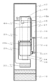
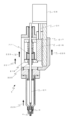
- the liquid material discharge device 1 of the second embodiment shown in FIG. 8 is mainly in that the storage container 2 is configured not by a syringe through which the valve rod 21 is inserted but by a syringe connected through an extending member 60. It is different from the first embodiment. Below, it demonstrates centering around difference with 1st embodiment, and omits description about a common element.
- the valve rod drive system (the part above the main body lower member 10) in the head cover 47 is the same as in the first embodiment.
- the actuator 28 reciprocates the actuator rod 31 up and down
- the valve rod 21 is reciprocated up and down via the drive transmission member 26, the upper slide block 37 and the lower slide block 38.
- the main body lower member 10 of the second embodiment is different from the first embodiment in that it is continuous with the extending portion 58 extending downward.
- the main body lower member 10 and the extending portion 58 may be configured integrally or may be configured by combining different members.
- the main body lower member 10 and the extending portion 58 include a through hole 13 extending in the vertical direction.
- the lower end of the through hole 13 is fluidly connected to a liquid chamber 59 wider than the through hole 13 provided in the extending portion 58.
- An annular seal member C64 and a seal member D65 that prevent leakage of the liquid material are disposed in the through hole 13.
- the liquid chamber 59 is composed of a large-diameter space and a small-diameter space located below the large-diameter space, and the lower half of the valve rod 21 is disposed. More specifically, the tip portion of the large diameter portion of the valve rod 21 is disposed in the large diameter space of the liquid chamber 59, and the tip portion of the small diameter portion of the valve rod 21 is disposed in the small diameter space of the liquid chamber 59. .
- the large-diameter space and the small-diameter space constituting the liquid chamber 59 are both wider than the tip portions of the valve rod 21, and when the valve rod 21 reciprocates up and down, the inner wall of the liquid chamber 59 and the valve rod 21 The side peripheral surface does not contact.
- the small-diameter space of the liquid chamber 59 located inside the distal end portion 58a of the extending portion constitutes the rod distal end portion insertion hole.
- the nozzle mounting member 5 is screwed into the distal end portion 58a of the extending portion.
- a valve seat 6 is disposed in the internal space of the nozzle mounting member 5 and is fixed by being sandwiched between the tip 58 a of the extending portion and the nozzle mounting member 5.
- One end of a side flow path 59 a communicates with the side surface of the large-diameter space of the liquid chamber 59.
- the other end of the side flow path 59 a communicates with the liquid supply port 62 of the extending member 60 disposed on the side surface of the extending portion 58.
- the extending member 60 is a block-shaped member having a liquid supply channel 61 whose one end forms a liquid supply port 62.
- a liquid supply joint 63 is disposed at the other end of the liquid supply channel 61.
- the liquid supply joint 63 is fluidly connected to the storage container (syringe) 2 and supplied with a liquid material pressurized by a compressed gas supply source (not shown).
- the syringe 2 may be connected to the liquid supply joint 63 via a liquid feed tube, or may be directly connected to the liquid supply joint 63.
- the valve rod 21 since the valve rod 21 is not inserted into the syringe 2, the replacement of the syringe 2 is easy.
- the discharge device 1 of the second embodiment also controls the lowering speed and acceleration (acceleration / deceleration time in the present embodiment) of the valve rod 21 by the actuator 28, thereby reducing the liquid pressure that occurs at the lower end of the valve rod 21. It is possible to suppress the generation of accompanying bubbles. Since the discharge operation is the same as that of the first embodiment, the description is omitted. Similarly to the first embodiment, the discharge device 1 of the second embodiment is mounted on the coating apparatus 101 and used in a negative pressure environment.
- the discharge device 1 of the second embodiment described above it is possible to control the rising speed and acceleration of the valve rod 21 to suppress the generation of bubbles, as in the first embodiment. Moreover, since the existing syringe 2 is connected via the extending member 60, maintenance is easy. Furthermore, since the valve rod 21 is not inserted into the syringe 2, the length of the valve rod 21 can be shortened, and consequently the blur at the lower end of the valve rod 21 can be reduced.
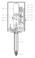
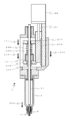
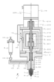
- the liquid material ejection device 1 according to the third embodiment shown in FIGS. 9 and 10 includes an outer frame 201, an inner frame 218, a sensor 43, and a detection plate 45 attached to the inner frame. It differs mainly from 1st embodiment by the point provided with the structure which the sensor 43 detects closure by moving. In the following, elements common to the first embodiment are denoted by the same reference numerals and description thereof may be omitted.
- FIG. 9 shows a partial cross-sectional front view of the ejection device according to the third embodiment.
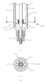
- FIG. 10 shows a CC arrow view in FIG.
- the actuator side in FIG. 10 is sometimes referred to as “rear surface”, the opposite side across the central axis is referred to as “front surface”, and the left and right surfaces positioned between the rear surface and the front surface are referred to as “side surfaces”.
- the valve rod 21 of the third embodiment is a linear member having a length extending from the vicinity of the valve seat member 6 to the vicinity of the actuator 28, and includes a first bush 208, a second bush 209, a rod interlocking member 221, a first interlocking member.
- the fixing member 222, the second fixing member 223, and the elastic member 224 are inserted.
- the first bush 208 and the second bush 209 are cylindrical members that are slidably supported on the outer periphery of the valve rod 21 and function as guide members that prevent the valve rod 21 from moving.
- the straightness of the valve rod 21 is made good by the guides of the first bush 208 and the second bush 209, thereby preventing the displacement of the contact position between the lower end of the valve rod 21 and the valve seat 6.
- the upper side of the lower body member 10 is covered with a cover (not shown).
- a cover not shown.
- the structure (storage container 2, the nozzle 3, the valve seat 6, etc.) below the main body lower member 10 with which the discharge apparatus 1 of 3rd embodiment is provided it is the same as that of the discharge apparatus 1 of 1st embodiment.
- the main body lower member 10 is a plate-like member that includes an insertion portion 12 that protrudes downward, a protrusion portion 207 that protrudes upward, and a second bush insertion hole 213 for disposing a second bush 209 extending vertically.
- the gas supply joint 19 is connected to one side surface.
- the second bush insertion hole 213 is provided in the center of the main body lower member 10 so as to penetrate from the upper surface of the protruding portion 207 to the lower surface of the insertion portion 12 at the lower end.
- the diameter of the second bushing insertion hole 213 is substantially the same as that of the second bushing 209, but a part of the lower end side is smaller than the second bushing 209 (and larger than the diameter of the valve rod 21).
- the second bushing 209 is supported by the stepped portion formed here.
- a second bush presser 211 for fixing the second bush 209 is provided on the upper end side of the second bush insertion hole 213.
- a communication hole (not shown) that communicates the inside of the syringe 2 and the compressed gas flow path 18 is provided inside the insertion portion 12, and compressed gas is supplied into the syringe 2 from the communication hole.
- a seal member 214 that prevents leakage of compressed gas to the outside is provided.
- an outer frame 201 having a substantially rectangular parallelepiped shape having a space inside is provided so as to include a position detection mechanism 34 described later.
- a fitting hole 202 is provided in the lower portion of the outer frame 201, and a protruding portion 207 on the upper surface of the main body lower member 10 is fitted and fixed.
- An extension part 204 for arranging a first bush 208 that supports the valve rod 21 so as to be linearly movable is provided on the upper part of the outer frame 201, and the inner space of the outer frame 201 is provided inside the extension part 204.
- a first bush insertion hole 212 communicating with the first bushing is provided.
- the first bush insertion hole 212 is composed of a large diameter portion and a small diameter portion, and the first bush 208 is supported by the step portion.
- a first bush presser 210 for fixing the first bush 208 is provided at the upper end of the first bush insertion hole 212.
- An opening 206 through which the actuator rod 31 and the actuator support member 215 are inserted is provided on the back side of the extension 204 at the top of the outer frame 201.
- One side surface of the outer frame 201 (the left side surface in FIG. 9 is not limited to this, but may be the right side surface) is open, and an opening 203 is formed on the open side surface.
- a mounting plate 44 having a size to be configured is installed.
- a sensor 43 constituting the position detection mechanism 34 is fixed to the mounting plate 44.
- the sensor 43 of the third embodiment is a photo sensor.
- other types of sensors such as a fiber sensor, a photoelectric sensor, and a proximity sensor (high frequency oscillation type, capacitance type) are used. May be used. Details of the detection operation will be described later.
- the back portion 205 of the outer frame 201 is provided so as to protrude from the main body lower member 10 to the back side (see FIG. 10).
- a plate-like actuator support member 215 is provided on the front side (inner side) of the back portion 205.
- the actuator support member 215 extends from near the lower end of the slider 216 to above the extension portion 204 and supports the actuator 28 above the outer frame 201.
- the actuator 28 is configured by a stepping motor with a resolver and the speed and acceleration of the operation of the valve rod are controlled, but may be configured by other motors as in the first embodiment.
- the actuator support member 215 is provided with a slider 216 that can move on the slide rail 217 on the front side.
- the slider 216 is connected to the actuator rod 31 and the inner frame 218.
- the inner frame 218 is slightly smaller than the outer frame 201 and has a substantially rectangular parallelepiped shape having a space inside.
- the inner frame 218 is connected to the slider 216 and functions as a slide member that moves integrally with the slider 216.
- a first through hole 219 is provided in the upper part of the inner frame 218, a second through hole 220 is provided in the lower part of the inner frame 218, and the valve rod 21 is placed in each through hole (219, 220). It is extended.
- the diameter of the first through hole 219 is larger than the diameter of the valve rod 21 so that the valve rod 21 can move up and down without contact.
- a second fixing member 223 having a smaller diameter than the second through hole 220 is inserted into the second through hole 220.
- a rod interlocking member 221 is disposed in the internal space of the inner frame 218, and the valve rod 21 is fixedly inserted into the through hole of the rod interlocking member 221.
- the rod interlocking member 221 is fixed to the valve rod 21 by the first fixing member 222 and the second fixing member 223 sandwiching the rod interlocking member 221 from above and below. More specifically, a screw is formed on the outer peripheral surface of the portion to which each fixing member (222, 223) of the valve rod 21 is attached, and is formed on the inner peripheral surface of each fixing member (222, 223). Can be screwed onto the screw.
- the rod interlocking member 221 can be fixed at a desired position by adjusting the position of each fixing member (222, 223).
- the position of the rod interlocking member 221 is such that the bottom surface of the rod interlocking member 221 contacts the inner bottom surface (lower upper surface) of the inner frame 218 when the lower end of the valve rod 21 contacts the valve seat 6 (the contact position described above). It is good to adjust to the position (state of FIG. 9 or FIG. 10).
- the method of fixing the rod interlocking member 221 is not limited to this, and the rod interlocking member 221 may be divided into two parts and fixed by being sandwiched from the front and rear as in the first embodiment.
- An elastic member 224 through which the valve rod 21 and the first fixing member 222 are inserted is disposed between the rod interlocking member 221 and the top surface of the inner frame 218.
- One end of the elastic member 224 is in contact with the top surface of the inner frame 218, the other end is in contact with the upper surface of the rod interlocking member 221, and the valve rod 21 is biased downward via the rod interlocking member 221.
- a recess having substantially the same diameter as that of the elastic member 224 is provided on the upper surface of the rod interlocking member 221 so that the end portion of the elastic member 224 is not displaced.
- a recess having substantially the same diameter as the elastic member 224 may be provided on the top surface of the inner frame 218 that contacts the upper end of the elastic member 224.
- the elastic member 224 of this embodiment is a compression coil spring, and a repulsive force (compression force) equivalent to the force required to move the valve rod 21, the rod interlocking member 221, the first fixing member 222, and the second fixing member 223.
- a detection plate 45 is installed on the outer surface of the inner frame 218 so as to face the sensor 43.
- This detection plate 45 constitutes the position detection mechanism 34 together with the sensor 43 as in the first embodiment.
- the sensor 43 may be disposed on the outer surface of the inner frame 218, and the detection plate 45 may be provided on the mounting plate 44 opposed thereto.
- the first bush 208, the elastic member 224, the rod interlocking member 221, the second bush 209, the valve seat 6, and the nozzle 3 are disposed on the same central axis as the central axis 225 of the valve rod 21. Therefore, no moment load is applied to the valve rod 21. Therefore, the straightness of the valve rod 21 is improved, the blur at the lower end of the valve rod 21 is reduced, and the displacement of the contact position between the valve rod 21 and the valve seat 6 is reduced. That is, the tip of the valve rod 21 can reliably close the communication hole 7 of the valve seat 6, and liquid does not leak when closed.
- the bushes (208, 209) that support the valve rod 21 so as to be linearly movable are arranged not only at the central portion (second bush 209) of the valve rod 21, but also at the end portion (first bush 208) of the valve rod 21.
- This also improves the straightness of the valve rod 21, reduces the blurring of the lower end of the valve rod 21, and contributes to reducing the displacement of the contact position between the valve rod 21 and the valve seat 6.
- the distance between the first bush 208 and the second bush 209 and the distance between the second bush 209 and the valve closing point (the contact point between the valve rod 21 end and the valve seat 6) should be substantially the same distance. In some cases, blurring at the lower end of the valve rod 21 may be further suppressed.
- the strength Pii of the compression spring which is the elastic member 224 is equal to the force required to move the valve rod 21, the rod interlocking member 221, the first fixing member 222 and the second fixing member 223, the spring 224 does not substantially contract (therefore, the bottom surface of the rod interlocking member 221 is in contact with the inner bottom surface of the inner frame 218 during the first lowering operation).
- the valve rod 21 is also lowered (reference numeral 233), and the lower end of the valve rod 21 is in contact with the valve seat 6. Thereby, the communication between the discharge flow path 4 and the storage container 2 is blocked, and the outflow of the liquid material from the discharge port is stopped.
- the elastic member 224 contracts, and a force that urges the rod interlocking member 221 downward acts as a repulsive force (reference numeral). 236).
- This force is a force that presses the valve rod 21 against the valve seat 6 (reference numeral 237), and the actuator rod 31 is further lowered by a predetermined distance (for example, 1 mm) from the initial detection position as in the first embodiment. Located in a safe closed position. As a result, the valve seat 6 is reliably closed by the valve rod 21.
- the discharge operation is the same as that of the first embodiment, the description is omitted.
- the discharge device 1 of the third embodiment is mounted on the coating device 101 and used in a negative pressure environment. Also with the discharge device 1 of the third embodiment described above, it is possible to suppress the decrease in the liquid pressure that occurs near the lower end of the valve rod 21 and the generation of bubbles associated therewith, as in the first embodiment.
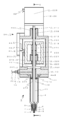
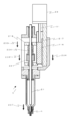
- the liquid material discharge device 1 of the fourth embodiment shown in FIG. 14 includes an outer frame 201, an inner frame 218, a sensor 43, and a detection plate 45 attached to the inner frame, and the inner frame moves up and down.
- the sensor 43 has a configuration for detecting closing, but is mainly different from the third embodiment in that it includes an extension member 60 similar to the second embodiment.
- elements common to the third embodiment are denoted by the same reference numerals, and description thereof may be omitted.
- the fourth embodiment also has a valve rod 21 having a length extending to the vicinity of the actuator 28, a first bush 208 through which the valve rod 21 is inserted, a second bush 209, a rod interlocking member 221, a first A first fixing member 222, a second fixing member 223, and an elastic member 224 are provided.
- the guides of the first bush 208 and the second bush 209 improve the straightness of the valve rod 21 and prevent the displacement of the contact position between the lower end of the valve rod 21 and the valve seat 6.
- 4th embodiment is provided with the extending member 60 which connects the syringe 2 and the liquid chamber 59 similarly to 2nd embodiment.
- the length of the valve rod 21 can be shortened, and consequently the blur at the lower end of the valve rod 21 can be reduced.
- the discharge device 1 of the fourth embodiment is mounted on the coating device 101 and used in a negative pressure environment. Also with the ejection device 1 of the fourth embodiment described above, it is possible to control the rising speed and acceleration of the valve rod 21 to suppress the generation of bubbles, as in the first to third embodiments. Moreover, since the existing syringe 2 is connected via the extending member 60, maintenance is easy.
- FIG. 15 is a partial cross-sectional view of the discharge device according to the fifth embodiment.
- (a) is a front view and
- (b) is a DD arrow view in (a).
- FIG. 15A the vicinity of the lower end of the valve rod is shown enlarged.
- the discharge device 1 of the fifth embodiment includes a rod support mechanism 238 that is formed over the entire length of the inner cylinder 8 inside the inner cylinder 8 of the syringe 2.
- the rod support mechanism 238 includes four rod support sliding portions 239 and four communication grooves 240.
- the four rod support sliding portions 239 and the four communication grooves 240 are annularly arranged at equal intervals, and each of the rod support slide portion 239 and the communication groove 240 is inside.
- the peripheral surface constitutes the inner peripheral surface of the inner cylinder 8.
- the valve rod 21 is the same as the first to fourth embodiments, and is a stepped rod having a small diameter near the lower end.
- the four rod support sliding portions 239 function as guide members that improve the straightness by sliding and supporting the outer periphery of the small diameter portion of the valve rod 21.
- the communication groove 240 which connects the large diameter part of the syringe 2 and the communication hole 7 of the valve seat 6 is provided. The liquid material stored in the large diameter portion of the syringe 2 is supplied to the communication hole 7 through the four communication grooves 240.
- the rod support sliding portion 239 and the communication groove 240 are provided at four locations, respectively, but the number is not limited to this and may be two or three, or five or more. May be. When arranging the plurality of rod support sliding portions 239 and the communication groove 240, it is preferable to arrange them at equal intervals.
- the rod support mechanism 238 is integrally formed with the inner cylinder 8 of the syringe 2, but the rod support mechanism 238 may be configured as a separate part and retrofitted to the existing syringe 2.
- the rod support mechanism 238 is provided near the lower end portion of the valve rod 21 (near the contact position with the valve seat 6), thereby reducing the blur at the lower end portion of the valve rod 21 and eventually The displacement of the contact position with the valve seat 6 can be reduced. Thereby, the communication hole 7 of the valve seat 6 can be reliably closed by the lower end of the valve rod 21.
- the rod support mechanism 238 of this embodiment can be applied to any of the first to fourth embodiments described above. However, when applied to the third or fourth embodiment, the rod support mechanism 238 is disposed in the length direction of the valve rod 21. By guiding at the three locations of the first bush 208, the second bush 209, and the rod support mechanism 238, the straightness of the valve rod 21 can be remarkably enhanced.
- FIG. 16 is a partial cross-sectional view of the discharge device according to the sixth embodiment.
- (a) is a front view and
- (b) is an EE arrow view in (a).
- FIG. 16A the vicinity of the lower end of the valve rod is shown enlarged.
- a rod support mechanism 238 that supports the valve rod 21 is provided in the large diameter portion above the inner cylinder 8 of the syringe 2.
- the rod support mechanism 238 includes a third bush 241, a partition member 242 having a third bush insertion hole 243 and a liquid communication hole 244, and a third bush presser 235.
- the third bush 241 is a cylindrical member that is slidably supported on the outer periphery of the valve rod 21 and functions as a guide member that prevents the valve rod 21 from blurring.
- the partition member 242 is a plate-like body including a third bush insertion hole 243 disposed at the center and eight liquid communication holes 244 disposed at equal intervals so as to surround the third bush insertion hole 243.
- the third bush 241 is fitted into the third bush insertion hole 243 and is fixed by the third bush presser 235.
- the large-diameter portion of the syringe 2 is partitioned into an upper space and a lower space by a partition member 242, but a liquid material is supplied from the upper space to the lower space via the liquid communication hole 244.
- the diameter of the liquid communication hole 244 is set to a size that can sufficiently supply the liquid material while maintaining the strength to support the valve rod 21.
- the number of liquid communication holes 244 is not limited to eight, and can be any number (preferably a plurality). When providing a plurality of liquid communication holes 244, it is preferable to arrange them at regular intervals with respect to the center of the syringe 2.
- the rod support mechanism 238 is integrally formed on the large-diameter portion of the syringe 2, but the rod support mechanism 238 may be configured as a separate part and retrofitted to the existing syringe 2.
- the rod support mechanism 238 is provided in the large diameter portion of the valve rod 21, thereby reducing the blur at the lower end of the valve rod 21, and thus reducing the displacement of the contact position between the valve rod 21 and the valve seat 6. can do.
- the rod support mechanism 238 of this embodiment can be applied to any of the first to fourth embodiments described above. However, when applied to the third or fourth embodiment, the rod support mechanism 238 is disposed in the length direction of the valve rod 21. By guiding with the three bushes, the straightness of the valve rod 21 can be remarkably enhanced.
Landscapes
- Engineering & Computer Science (AREA)
- General Engineering & Computer Science (AREA)
- Coating Apparatus (AREA)
- Mechanical Engineering (AREA)
- Application Of Or Painting With Fluid Materials (AREA)
Priority Applications (4)
| Application Number | Priority Date | Filing Date | Title |
|---|---|---|---|
| US16/305,553 US11458501B2 (en) | 2016-05-30 | 2017-05-25 | Liquid material discharge device, and application device and application method therefor |
| DE112017002707.1T DE112017002707T5 (de) | 2016-05-30 | 2017-05-25 | Flüssigmaterialabgabevorrichtung und Auftragsvorrichtung und Auftragsverfahren für diese |
| CN201780034025.5A CN109311043B (zh) | 2016-05-30 | 2017-05-25 | 液体材料吐出装置、其涂布装置及涂布方法 |
| KR1020187031927A KR102306482B1 (ko) | 2016-05-30 | 2017-05-25 | 액체 재료 토출 장치, 그 도포 장치 및 도포 방법 |
Applications Claiming Priority (2)
| Application Number | Priority Date | Filing Date | Title |
|---|---|---|---|
| JP2016-107831 | 2016-05-30 | ||
| JP2016107831A JP6739786B2 (ja) | 2016-05-30 | 2016-05-30 | 液体材料吐出装置、その塗布装置および塗布方法 |
Publications (1)
| Publication Number | Publication Date |
|---|---|
| WO2017208956A1 true WO2017208956A1 (ja) | 2017-12-07 |
Family
ID=60477579
Family Applications (1)
| Application Number | Title | Priority Date | Filing Date |
|---|---|---|---|
| PCT/JP2017/019503 WO2017208956A1 (ja) | 2016-05-30 | 2017-05-25 | 液体材料吐出装置、その塗布装置および塗布方法 |
Country Status (7)
Cited By (1)
| Publication number | Priority date | Publication date | Assignee | Title |
|---|---|---|---|---|
| CN119793765A (zh) * | 2025-03-13 | 2025-04-11 | 山西绿建智造装饰铝板科技有限公司 | 一种抗菌铝单板的表面处理设备及处理方法 |
Families Citing this family (5)
| Publication number | Priority date | Publication date | Assignee | Title |
|---|---|---|---|---|
| DE102020102871A1 (de) * | 2020-02-05 | 2021-08-05 | Atlas Copco Ias Gmbh | Vorrichtung zum Auftragen von viskosem Material auf Werkstücke |
| JP6947879B1 (ja) * | 2020-06-09 | 2021-10-13 | 株式会社ソディック | 軽金属射出装置の逆流防止装置および軽金属射出装置の逆流防止方法 |
| KR102518407B1 (ko) * | 2021-06-30 | 2023-04-05 | 주식회사 인스텍 | 레이저 성형 장치용 파우더 공급 호퍼 |
| CN114798216B (zh) * | 2022-05-09 | 2023-05-23 | 中国电建集团贵州工程有限公司 | 舱室油漆喷洒修复装置 |
| CN120394293B (zh) * | 2025-06-25 | 2025-09-02 | 江苏汇琨科技有限公司 | 一种线束加工用灌胶设备 |
Citations (9)
| Publication number | Priority date | Publication date | Assignee | Title |
|---|---|---|---|---|
| JPH10151393A (ja) * | 1996-11-26 | 1998-06-09 | Three Bond Co Ltd | 材料塗布装置 |
| JPH11197571A (ja) * | 1998-01-12 | 1999-07-27 | Nordson Kk | 吐出ガンの弁機構の開閉速度制御方法及び装置並びに液状体の吐出塗布方法 |
| JP2000317369A (ja) * | 1999-05-07 | 2000-11-21 | Cimeo Precision Co Ltd | 定量吐出装置 |
| JP2001246298A (ja) * | 2000-03-07 | 2001-09-11 | Matsushita Electric Ind Co Ltd | 流体吐出装置及び流体吐出方法 |
| JP2002021715A (ja) * | 2000-07-10 | 2002-01-23 | Matsushita Electric Ind Co Ltd | 流体供給装置及び流体供給方法 |
| JP2002513674A (ja) * | 1998-05-01 | 2002-05-14 | ノルドソン コーポレーション | 少量の液体材料を供給する方法および装置 |
| JP2002282740A (ja) * | 2001-03-27 | 2002-10-02 | Musashi Eng Co Ltd | 液滴の形成方法および液滴定量吐出装置 |
| JP2008008232A (ja) * | 2006-06-30 | 2008-01-17 | Saginomiya Seisakusho Inc | 定量送液ポンプおよびそれを用いた薬液塗布装置 |
| WO2013118669A1 (ja) * | 2012-02-06 | 2013-08-15 | 武蔵エンジニアリング株式会社 | 液体材料の吐出装置および吐出方法 |
Family Cites Families (32)
| Publication number | Priority date | Publication date | Assignee | Title |
|---|---|---|---|---|
| US5451260A (en) * | 1994-04-15 | 1995-09-19 | Cornell Research Foundation, Inc. | Method and apparatus for CVD using liquid delivery system with an ultrasonic nozzle |
| US5747102A (en) | 1995-11-16 | 1998-05-05 | Nordson Corporation | Method and apparatus for dispensing small amounts of liquid material |
| US6267266B1 (en) | 1995-11-16 | 2001-07-31 | Nordson Corporation | Non-contact liquid material dispenser having a bellows valve assembly and method for ejecting liquid material onto a substrate |
| JP3068019B2 (ja) * | 1996-12-27 | 2000-07-24 | 日本たばこ産業株式会社 | 薬剤散布装置及び方法 |
| US5875922A (en) * | 1997-10-10 | 1999-03-02 | Nordson Corporation | Apparatus for dispensing an adhesive |
| US6484885B1 (en) | 1998-05-01 | 2002-11-26 | Cpi Sales & Mfg., Inc. | Solids raised screens |
| US20030121836A1 (en) | 1998-05-01 | 2003-07-03 | Lilie Glenn T. | Solids raised screens |
| JP2001113212A (ja) | 1999-10-20 | 2001-04-24 | Noiberuku Kk | 液体吐出装置 |
| EP1132615B1 (en) | 2000-03-07 | 2006-11-08 | Matsushita Electric Industrial Co., Ltd. | Fluid dispenser |
| US6679685B2 (en) | 2000-03-07 | 2004-01-20 | Matsushita Electric Industrial Co., Ltd. | Method and device for discharging viscous fluids |
| KR100948220B1 (ko) * | 2002-03-19 | 2010-03-18 | 도쿄엘렉트론가부시키가이샤 | 도포처리방법 및 도포처리장치 |
| US7143993B2 (en) * | 2003-01-17 | 2006-12-05 | Siemens Vdo Automotive, Inc. | Exhaust gas recirculation valve having a rotary motor |
| NZ542701A (en) * | 2003-03-13 | 2007-09-28 | Great Stuff Inc | Remote control for hose valve and reel |
| US20050001869A1 (en) * | 2003-05-23 | 2005-01-06 | Nordson Corporation | Viscous material noncontact jetting system |
| US7918435B2 (en) * | 2003-10-30 | 2011-04-05 | Fluid Management, Inc. | Combination gravimetric and volumetric dispenser for multiple fluids |
| JP4311549B2 (ja) | 2004-02-02 | 2009-08-12 | Tdk株式会社 | 液体材料塗布方法 |
| JP2006281178A (ja) * | 2005-04-05 | 2006-10-19 | Noiberuku Kk | シリンジポンプ |
| JP5068942B2 (ja) | 2005-10-18 | 2012-11-07 | アピックヤマダ株式会社 | 真空ディスペンス装置 |
| KR100840482B1 (ko) * | 2006-02-27 | 2008-06-20 | 다이니폰 스크린 세이조우 가부시키가이샤 | 도포 장치 및 도포 방법 |
| JP2010528230A (ja) | 2007-05-18 | 2010-08-19 | エンフィールド テクノロジーズ エルエルシー | 電子制御バルブおよびそれを含むシステム |
| CA2600323C (en) * | 2007-09-20 | 2009-12-29 | Westport Power Inc. | Directly actuated valve with a strain-type actuator and a method of operating same |
| DE102007045513B4 (de) * | 2007-09-24 | 2015-03-19 | Continental Automotive Gmbh | Verfahren und Vorrichtung zum Zumessen eines Fluids |
| WO2009104421A1 (ja) | 2008-02-21 | 2009-08-27 | 武蔵エンジニアリング株式会社 | 液体材料の吐出装置および方法 |
| WO2009108377A1 (en) | 2008-02-27 | 2009-09-03 | Enfield Technologies, Llc | Method and device for controlling load and voltage in voice coils |
| JP5164774B2 (ja) * | 2008-10-01 | 2013-03-21 | パナソニック株式会社 | ペースト塗布装置およびペースト塗布方法 |
| US9162249B2 (en) | 2008-10-01 | 2015-10-20 | Panasonic Intellectual Property Management Co., Ltd. | Paste dispenser for applying paste containing fillers using nozzle with pin and application method using the same |
| JP5419616B2 (ja) * | 2009-09-25 | 2014-02-19 | 武蔵エンジニアリング株式会社 | 気泡混入防止機構および該機構を備える液体材料吐出装置並びに液体材料吐出方法 |
| KR101612495B1 (ko) | 2011-12-27 | 2016-04-14 | 다이호 고교 가부시키가이샤 | 밸브 장치 |
| KR101544070B1 (ko) | 2012-06-25 | 2015-08-12 | 한국생산기술연구원 | 하드 로이 유리 제조장치 및 이를 이용한 하드 로이 유리 제조방법 |
| CN203098881U (zh) * | 2013-02-01 | 2013-07-31 | 罗艳芳 | 一种无外泄漏阀门 |
| JP6364168B2 (ja) | 2013-09-30 | 2018-07-25 | 武蔵エンジニアリング株式会社 | 液体材料吐出装置および塗布方法 |
| KR20150061593A (ko) | 2013-11-27 | 2015-06-04 | 시바우라 메카트로닉스 가부시끼가이샤 | 도포 장치, 도포 방법, 표시 장치용 부재의 제조 장치 및 표시 장치용 부재의 제조 방법 |
-
2016
- 2016-05-30 JP JP2016107831A patent/JP6739786B2/ja active Active
-
2017
- 2017-05-25 US US16/305,553 patent/US11458501B2/en active Active
- 2017-05-25 WO PCT/JP2017/019503 patent/WO2017208956A1/ja active Application Filing
- 2017-05-25 CN CN201780034025.5A patent/CN109311043B/zh active Active
- 2017-05-25 DE DE112017002707.1T patent/DE112017002707T5/de active Pending
- 2017-05-25 KR KR1020187031927A patent/KR102306482B1/ko active Active
- 2017-05-26 TW TW106117598A patent/TWI770027B/zh active
Patent Citations (9)
| Publication number | Priority date | Publication date | Assignee | Title |
|---|---|---|---|---|
| JPH10151393A (ja) * | 1996-11-26 | 1998-06-09 | Three Bond Co Ltd | 材料塗布装置 |
| JPH11197571A (ja) * | 1998-01-12 | 1999-07-27 | Nordson Kk | 吐出ガンの弁機構の開閉速度制御方法及び装置並びに液状体の吐出塗布方法 |
| JP2002513674A (ja) * | 1998-05-01 | 2002-05-14 | ノルドソン コーポレーション | 少量の液体材料を供給する方法および装置 |
| JP2000317369A (ja) * | 1999-05-07 | 2000-11-21 | Cimeo Precision Co Ltd | 定量吐出装置 |
| JP2001246298A (ja) * | 2000-03-07 | 2001-09-11 | Matsushita Electric Ind Co Ltd | 流体吐出装置及び流体吐出方法 |
| JP2002021715A (ja) * | 2000-07-10 | 2002-01-23 | Matsushita Electric Ind Co Ltd | 流体供給装置及び流体供給方法 |
| JP2002282740A (ja) * | 2001-03-27 | 2002-10-02 | Musashi Eng Co Ltd | 液滴の形成方法および液滴定量吐出装置 |
| JP2008008232A (ja) * | 2006-06-30 | 2008-01-17 | Saginomiya Seisakusho Inc | 定量送液ポンプおよびそれを用いた薬液塗布装置 |
| WO2013118669A1 (ja) * | 2012-02-06 | 2013-08-15 | 武蔵エンジニアリング株式会社 | 液体材料の吐出装置および吐出方法 |
Cited By (1)
| Publication number | Priority date | Publication date | Assignee | Title |
|---|---|---|---|---|
| CN119793765A (zh) * | 2025-03-13 | 2025-04-11 | 山西绿建智造装饰铝板科技有限公司 | 一种抗菌铝单板的表面处理设备及处理方法 |
Also Published As
| Publication number | Publication date |
|---|---|
| US11458501B2 (en) | 2022-10-04 |
| JP2017213487A (ja) | 2017-12-07 |
| KR20190015217A (ko) | 2019-02-13 |
| JP6739786B2 (ja) | 2020-08-12 |
| CN109311043B (zh) | 2021-04-09 |
| CN109311043A (zh) | 2019-02-05 |
| US20210220863A1 (en) | 2021-07-22 |
| TWI770027B (zh) | 2022-07-11 |
| TW201808470A (zh) | 2018-03-16 |
| KR102306482B1 (ko) | 2021-09-28 |
| DE112017002707T5 (de) | 2019-02-21 |
Similar Documents
| Publication | Publication Date | Title |
|---|---|---|
| WO2017208956A1 (ja) | 液体材料吐出装置、その塗布装置および塗布方法 | |
| WO2017208958A1 (ja) | 液体材料吐出装置、その塗布装置および塗布方法 | |
| JP5419616B2 (ja) | 気泡混入防止機構および該機構を備える液体材料吐出装置並びに液体材料吐出方法 | |
| TWI453069B (zh) | 於基材上分散黏性材料之方法及設備 | |
| KR101457465B1 (ko) | 탈포 기구를 구비한 액재 토출 장치 | |
| US9737945B2 (en) | Electrical discharge machining apparatus | |
| KR20170053619A (ko) | 디스펜서용 밸브 시트 | |
| KR20170015669A (ko) | 디스펜싱 장치 | |
| HK1262353A1 (en) | Liquid material discharge device, and application device and application method therefor | |
| HK1262353B (en) | Liquid material discharge device, and application device and application method therefor | |
| JP7066229B2 (ja) | 液体材料吐出装置、その塗布装置および塗布方法 | |
| US20230347560A1 (en) | Liquid introduction apparatus, adhesive dispensing apparatus and liquid introduction method | |
| KR101653139B1 (ko) | 전기 또는 전자 부품을 핸들링하기 위한 마운팅 헤드 | |
| CN111182977B (zh) | 喷嘴连接器、喷嘴连接器组、涂布装置及涂布系统 | |
| KR101225669B1 (ko) | 에어를 이용한 카트리지형 비접촉식 디스펜서 | |
| KR102486132B1 (ko) | 높이 조절형 전기수력학적 펌프 헤드 조립체 | |
| KR100373184B1 (ko) | 반도체 제조용 레진 토출장치 | |
| KR102424736B1 (ko) | 기체 유로를 구비하는 전기수력학적 펌프 헤드 조립체 | |
| KR102486133B1 (ko) | 튜브형 내부 전극을 구비하는 전기수력학적 펌프 헤드 조립체 | |
| JPH11247756A (ja) | 液体吐出装置 | |
| KR101015284B1 (ko) | 슬러리 공급 장치 | |
| KR101899243B1 (ko) | 스트로크 제어형 점성 용액 펌프 | |
| HK40000227A (en) | Liquid material discharge device, and application device and application method therefor | |
| JP2019021661A (ja) | 薬液交換補助装置 | |
| KR20180110787A (ko) | 스트로크 보정 방식 점성 용액 펌프 |
Legal Events
| Date | Code | Title | Description |
|---|---|---|---|
| DPE1 | Request for preliminary examination filed after expiration of 19th month from priority date (pct application filed from 20040101) | ||
| ENP | Entry into the national phase |
Ref document number: 20187031927 Country of ref document: KR Kind code of ref document: A |
|
| 121 | Ep: the epo has been informed by wipo that ep was designated in this application |
Ref document number: 17806513 Country of ref document: EP Kind code of ref document: A1 |
|
| 122 | Ep: pct application non-entry in european phase |
Ref document number: 17806513 Country of ref document: EP Kind code of ref document: A1 |