WO2017208732A1 - ウォッシャポンプ - Google Patents
ウォッシャポンプ Download PDFInfo
- Publication number
- WO2017208732A1 WO2017208732A1 PCT/JP2017/017386 JP2017017386W WO2017208732A1 WO 2017208732 A1 WO2017208732 A1 WO 2017208732A1 JP 2017017386 W JP2017017386 W JP 2017017386W WO 2017208732 A1 WO2017208732 A1 WO 2017208732A1
- Authority
- WO
- WIPO (PCT)
- Prior art keywords
- valve
- pump
- washer
- housing
- washer pump
- Prior art date
Links
Images


Classifications
-
- F—MECHANICAL ENGINEERING; LIGHTING; HEATING; WEAPONS; BLASTING
- F04—POSITIVE - DISPLACEMENT MACHINES FOR LIQUIDS; PUMPS FOR LIQUIDS OR ELASTIC FLUIDS
- F04D—NON-POSITIVE-DISPLACEMENT PUMPS
- F04D29/00—Details, component parts, or accessories
- F04D29/40—Casings; Connections of working fluid
- F04D29/42—Casings; Connections of working fluid for radial or helico-centrifugal pumps
- F04D29/426—Casings; Connections of working fluid for radial or helico-centrifugal pumps especially adapted for liquid pumps
- F04D29/4293—Details of fluid inlet or outlet
-
- B—PERFORMING OPERATIONS; TRANSPORTING
- B60—VEHICLES IN GENERAL
- B60S—SERVICING, CLEANING, REPAIRING, SUPPORTING, LIFTING, OR MANOEUVRING OF VEHICLES, NOT OTHERWISE PROVIDED FOR
- B60S1/00—Cleaning of vehicles
- B60S1/02—Cleaning windscreens, windows or optical devices
- B60S1/46—Cleaning windscreens, windows or optical devices using liquid; Windscreen washers
- B60S1/48—Liquid supply therefor
- B60S1/481—Liquid supply therefor the operation of at least part of the liquid supply being controlled by electric means
-
- F—MECHANICAL ENGINEERING; LIGHTING; HEATING; WEAPONS; BLASTING
- F04—POSITIVE - DISPLACEMENT MACHINES FOR LIQUIDS; PUMPS FOR LIQUIDS OR ELASTIC FLUIDS
- F04D—NON-POSITIVE-DISPLACEMENT PUMPS
- F04D13/00—Pumping installations or systems
- F04D13/16—Pumping installations or systems with storage reservoirs
-
- F—MECHANICAL ENGINEERING; LIGHTING; HEATING; WEAPONS; BLASTING
- F04—POSITIVE - DISPLACEMENT MACHINES FOR LIQUIDS; PUMPS FOR LIQUIDS OR ELASTIC FLUIDS
- F04D—NON-POSITIVE-DISPLACEMENT PUMPS
- F04D29/00—Details, component parts, or accessories
- F04D29/18—Rotors
- F04D29/22—Rotors specially for centrifugal pumps
- F04D29/2261—Rotors specially for centrifugal pumps with special measures
- F04D29/2283—Rotors specially for centrifugal pumps with special measures for reverse pumping action
-
- F—MECHANICAL ENGINEERING; LIGHTING; HEATING; WEAPONS; BLASTING
- F04—POSITIVE - DISPLACEMENT MACHINES FOR LIQUIDS; PUMPS FOR LIQUIDS OR ELASTIC FLUIDS
- F04D—NON-POSITIVE-DISPLACEMENT PUMPS
- F04D29/00—Details, component parts, or accessories
- F04D29/40—Casings; Connections of working fluid
- F04D29/42—Casings; Connections of working fluid for radial or helico-centrifugal pumps
- F04D29/44—Fluid-guiding means, e.g. diffusers
- F04D29/46—Fluid-guiding means, e.g. diffusers adjustable
- F04D29/48—Fluid-guiding means, e.g. diffusers adjustable for unidirectional fluid flow in reversible pumps
- F04D29/486—Fluid-guiding means, e.g. diffusers adjustable for unidirectional fluid flow in reversible pumps especially adapted for liquid pumps
-
- F—MECHANICAL ENGINEERING; LIGHTING; HEATING; WEAPONS; BLASTING
- F04—POSITIVE - DISPLACEMENT MACHINES FOR LIQUIDS; PUMPS FOR LIQUIDS OR ELASTIC FLUIDS
- F04D—NON-POSITIVE-DISPLACEMENT PUMPS
- F04D13/00—Pumping installations or systems
- F04D13/02—Units comprising pumps and their driving means
- F04D13/06—Units comprising pumps and their driving means the pump being electrically driven
Definitions
- the present invention relates to a washer pump that sucks liquid stored in a tank and injects the liquid onto a cleaning surface.
- the washer device includes a washer pump and a tank for storing a liquid (washer liquid).
- the washer pump is driven by operation of an operation switch, and injects liquid in the tank to each windshield according to the rotation direction of the motor.
- the windshield (cleaning surface) is cleanly cleaned by driving the wiper device and wiping the liquid sprayed onto the windshield with the wiper blade.
- Patent Document 1 There is a technique described in Patent Document 1, for example, for a washer pump that sucks liquid stored in a tank and injects the liquid onto a cleaning surface.
- the washer pump described in Patent Document 1 includes a storage chamber (pump chamber) for storing an impeller, first and second valve chambers (valve chambers) into which cleaning liquid (liquid) is introduced according to the rotation direction of the impeller, First and second passages (flow paths) that connect the storage chamber and the first and second valve chambers, a valve body (switching valve) that partitions the first and second valve chambers from each other, and a moving direction of the valve body And first and second liquid pipes (discharge holes) provided on both sides.
- a storage chamber for storing an impeller
- first and second valve chambers valve chambers into which cleaning liquid (liquid) is introduced according to the rotation direction of the impeller
- First and second passages flow paths
- valve body switching valve
- first and second liquid pipes discharge holes
- the liquid flows from the pump chamber toward the flow path by the rotation of the impeller, and the liquid that flows into the flow path vigorously flows through the flow path. Thereafter, the liquid that has flowed through the flow path is vigorously discharged from the end of the valve chamber into the valve chamber. That is, the liquid discharged from the flow channel is rapidly diffused inside the valve chamber. And the liquid discharged
- An object of the present invention is to provide a washer pump capable of suppressing a reduction in injection capacity and achieving further reduction in size and weight.
- a washer pump that sucks liquid stored in a tank and injects the liquid onto a cleaning surface
- a motor that rotates in a forward and reverse direction
- an impeller that is rotated by the motor
- a pump chamber in which the impeller is accommodated a pair of valve chambers into which the liquid flows in according to the rotation direction of the impeller, a switching valve that partitions the pair of valve chambers, and a moving direction of the switching valve.
- a pair of discharge holes and a pair of flow paths respectively provided between the pump chamber and the pair of valve chambers, wherein the pump chamber, the valve chamber, the discharge holes, and the flow path are respectively housings
- the valve chamber side of the flow path extends to the position of the discharge hole.
- the flow passage area on the pump chamber side of at least one of the pair of flow passages is smaller than the flow passage area on the valve chamber side.
- the one channel includes an inclined wall that gradually increases the channel area from the pump chamber side toward the valve chamber side.
- the one channel has an opposing wall that faces the inclined wall, and the opposing wall is provided near the side wall of the housing in parallel with the side wall, The housing is provided inside the side wall.
- the flow area on the pump chamber side of the one flow path is smaller than the flow area on the pump chamber side of the other flow path of the pair of flow paths.
- the one flow path is provided corresponding to the ejection of the liquid onto the cleaning surface on the front side of the vehicle.
- the pump chamber, the valve chamber, the discharge hole, and the flow path are integrally provided in the housing, the liquid flow is hindered in the liquid flow path when these are formed as separate members. Since a step or the like need not be formed, the pressure loss of the liquid can be reduced.
- valve chamber side of the flow path extends to the position of the discharge hole, the liquid flowing out from the flow path can be discharged at a portion closer to the center of the valve chamber than before.
- the outlet portion of the flow path and the inlet portion of the discharge hole can be brought close to each other, and the turbulent flow of the liquid inside the valve chamber can be suppressed, thereby reducing the pressure loss.
- FIG. 5 is a cross-sectional view of the commutator along the line AA in FIG. 4.
- FIG. 5 is a cross-sectional view of the armature core taken along line BB in FIG. 4. It is explanatory drawing explaining the brush structure with which the inner side of a motor cover is mounted
- (A), (b) is sectional drawing explaining the position of the discharge hole with respect to the opening part of a valve chamber.
- (A), (b) is a perspective view which shows a valve unit. It is sectional drawing which follows the DD line
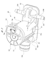
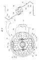
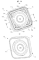
- FIG. 1 is an exploded perspective view for explaining a mounting state of the washer pump of the present invention in a washer tank.
- a washer tank (tank) 10 is formed in a hollow, substantially rectangular parallelepiped shape using a white and translucent plastic material or the like, and a cleaning liquid (liquid) W such as a washer liquid is stored therein.
- the washer tank 10 includes a tank wall 12 that forms an outline of the washer tank 10, and a pump mounting portion 13 is integrally provided on the bottom side (lower side in the drawing) of the tank wall 12.
- the pump mounting portion 13 is provided to be recessed inside the washer tank 10, and the pump mounting portion 13 is provided with a pair of tank side holding portions 14 that hold the housing 30 of the washer pump 20.
- Each tank side holding part 14 is provided by projecting a part of the pump mounting part 13 inward in the radial direction, and the separation dimension between the tank side holding parts 14 is set to W1.
- the insertion hole 15 into which the suction pipe 32c of the washer pump 20 is inserted is provided on the bottom side of the pump mounting part 13.
- a grommet 16 formed in an annular shape by an elastic material such as rubber is mounted in the insertion hole 15. The grommet 16 is elastically deformed between the washer tank 10 and the suction pipe 32c, and seals between the insertion hole 15 and the suction pipe 32c. Thereby, leakage of the cleaning liquid W from between the washer tank 10 and the washer pump 20 is prevented, and rattling of the washer pump 20 with respect to the washer tank 10 is prevented.
- the washer tank 10 and the washer pump 20 can be easily installed in an engine room (not shown) of a vehicle such as an automobile. As shown in FIG. 1, the washer device is installed in the engine room so that the pump mounting portion 13 of the washer tank 10 is on the lower side.
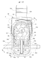
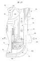
- FIG. 2 is a perspective view of the washer pump of FIG. 1 viewed from the motor cover side
- FIG. 3 is a perspective view of the washer pump of FIG. 1 viewed from the cover member side
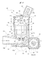
- FIG. 4 is a washer pump along the axial direction of the armature shaft. The cross-sectional views are respectively shown.
- the washer pump 20 includes a housing 30 having a substantially T-shaped cross section formed by injection molding of a resin material such as plastic.
- the housing 30 is a large part among the parts constituting the washer pump 20, and forms an outline of the washer pump 20. In other words, the washer pump 20 having a small physique can be realized by downsizing the housing 30.
- the housing 30 includes a motor housing portion 31, a pump housing portion 32, and a valve body housing portion 33.
- FIG. 5 (a) and 5 (b) are perspective views for explaining a magnet fixing structure to the motor housing portion
- FIG. 6 is a cross-sectional view of the motor housing portion along a direction intersecting the axial direction of the armature shaft. .
- the motor housing portion 31 is formed in a substantially cylindrical shape, and a motor chamber 31a for housing the motor 40 is formed on the radially inner side thereof.
- a plurality of support ribs 31 b that support the radially outer side of the yoke 41 that forms the motor 40 are provided on the radially inner side of the motor housing portion 31.
- These support ribs 31 b also serve to reinforce the motor housing portion 31.
- Each support rib 31 b extends in the axial direction of the motor housing portion 31 and is disposed at a predetermined interval in the circumferential direction of the motor housing portion 31. Thereby, rattling in the motor accommodating part 31 of the motor 40 is suppressed, without making the mounting operation
- a pair of rib groups RB each including three reinforcing ribs 31c are provided on the outer side in the radial direction of the motor accommodating portion 31, that is, on the outer peripheral portion. These rib groups RB are provided so as to correspond to the downsizing (thinning) of the motor housing portion 31 and play a role of reinforcing the motor housing portion 31.
- a total of six reinforcing ribs 31 c extend in the axial direction of the motor housing portion 31, similarly to the support ribs 31 b provided on the radially inner side of the motor housing portion 31.
- the pair of rib groups RB are arranged at an interval of about 180 degrees so as to face each other about the axis of the motor housing portion 31.
- the distance between the tops of the reinforcing ribs 31c farthest from each other is set to W2.
- the motor housing portion 31 forming the housing 30 is a portion held by each tank side holding portion 14 (see FIG. 1) of the washer tank 10.
- a pair of reinforcing ribs 31c having a mutual separation dimension of W2 are sandwiched between the tank side holding portions 14. That is, the separation dimension W2 at the top of the reinforcing ribs 31c farthest from each other is set to be slightly larger than the separation dimension W1 between the tank holding parts 14 (W2> W1).
- W2> W1 the separation dimension W1 between the tank holding parts 14
- a magnet support portion 31 d is provided on the radially inner side of the motor housing portion 31.
- the magnet support portion 31 d is provided so as to protrude from the bottom portion BT of the motor housing portion 31, and is disposed on the radially inner side of the motor housing portion 31 with a predetermined gap S.
- the magnet support portion 31d is formed in a substantially arc shape in cross section, and at one side in the width direction (lower side in FIG. 6) of the pair of magnets 42 forming the motor 40 on both sides in the width direction (left and right sides in FIG. 6). I support it.
- a pair of magnet mounting portions 31 e are provided on the radially inner side of the motor housing portion 31. These magnet mounting portions 31e are arranged at an interval of 180 degrees so as to face each other around the axis of the motor housing portion 31.
- Each magnet placement portion 31e is formed in a shape substantially the same as the magnet support portion 31d, and is provided so as to protrude from the bottom portion BT of the motor housing portion 31 in the same manner as the magnet support portion 31d.
- Each magnet placement portion 31e supports one end side in the height direction of the pair of magnets 42 (the lower side in FIG. 4).
- a first opening 31 f is formed on the side opposite to the bottom side along the axial direction of the motor housing portion 31 (upper side in FIG. 4), and the first opening 31 f is formed by the motor cover 50. It is blocked. That is, the motor chamber 31 a is closed with the motor cover 50.
- the motor cover 50 and the motor accommodating part 31 are mutually adhere
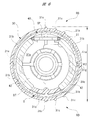
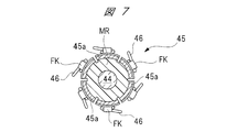
- FIG. 7 is a cross-sectional view of the commutator along the line AA in FIG. 4
- FIG. 8 is a cross-sectional view of the armature core along the line BB in FIG. 4
- FIG. 9 is a brush structure attached to the inside of the motor cover. Explanatory drawing explaining each is shown.
- a motor 40 is accommodated in the motor accommodating portion 31.
- the motor 40 includes a motor cover 50 that closes the first opening 31 f of the motor housing 31.
- the motor 40 includes a yoke 41 whose section is formed in a substantially cylindrical shape by pressing a steel plate or the like, and a portion along the circumferential direction is cut away. 5 and 6, the outer side in the radial direction of the yoke 41 is supported by a plurality of support ribs 31b, and the yoke 41 enters the predetermined gap S. That is, the magnet support portion 31 d is disposed on the radially inner side of the yoke 41.
- the yoke 41 is formed with a notch 41 a extending in the axial direction, and the notch 41 a has a positioning protrusion formed on the radially inner side of the motor accommodating portion 31. 31g has entered. Accordingly, the yoke 41 is fixed in a state where the yoke 41 is positioned in the circumferential direction of the motor housing portion 31. Although the positioning and fixing of the yoke 41 in the axial direction of the motor housing portion 31 is not shown in detail, the yoke 41 is partly attached to one side of the bottom portion BT of the motor housing portion 31 (the lower side in FIG. 4). ) Is performed by partial contact. In this way, the yoke 41 (motor 40) is fixed inside the motor chamber 31a.
- Two (two-pole) magnets (permanent magnets) 42 are fixed inside the yoke 41 in the radial direction. Specifically, the radially inner side of one magnet 42 is magnetized to the S pole, and the radially inner side of the other magnet 42 is magnetized to the N pole.
- Each magnet 42 is formed in a substantially arc shape in cross section, and its radial outer side is fixed in contact with the radial inner side of the yoke 41. That is, the yoke 41 forms a magnetic path through which the magnetic lines of force of each magnet 42 pass.
- each magnet 42 is in contact with each magnet placement portion 31e, and one end in the width direction of each magnet 42 is in contact with both sides in the width direction of the magnet support portion 31d.
- the other end in the height direction of each magnet 42 (upper side in FIG. 4) is a plurality of support claws formed on the other axial side of the yoke 41 (upper side in FIG. 4).
- the other end in the width direction (upper side in FIG. 6) of each magnet 42 is elastically supported by a spring pin SP formed in a substantially U shape. That is, each magnet 42 is pressed against the yoke 41 by the spring force of the spring pin SP without being rattled.
- each magnet 42 is fixed to the yoke 41 with one spring pin SP and the magnet support portion 31d without using two spring pins SP. That is, since the magnet support portion 31d is made of a nonmagnetic material, it is not necessary to adversely affect the magnetic path formed by each magnet 42. Therefore, each magnet 42 can be further reduced in size, and thus the washer pump 20 can be further reduced in size and weight.
- an armature core 43 is rotatably provided on the inner side in the radial direction of each magnet 42 through a predetermined gap (air gap).
- An armature shaft (rotating shaft) 44 passes through and is fixed to the rotation center of the armature core 43, that is, the rotation center of the motor 40. That is, the armature shaft 44 rotates together with the armature core 43.
- One end side in the axial direction of the armature shaft 44 is rotatably supported by a first bearing B1 mounted on the bottom portion BT of the motor housing portion 31, and the other end side in the axial direction of the armature shaft 44 is mounted on the motor cover 50.
- the second bearing B2 is rotatably supported.
- a commutator (commutator) 45 to which the two power supply brushes 54 are slidably contacted is fixed near the armature core 43 on the other axial end side of the armature shaft 44.
- the commutator 45 includes a total of six segments (commutator pieces) 45 a, and these segments 45 a are equally spaced in the circumferential direction (60 degrees) around the axis of the armature shaft 44. Are arranged at intervals).
- Each segment 45a is hardened by mold resin MR so that it may have a substantially cylindrical shape.
- the coils 46 are hooked on the hook portions FK of the segments 45a.
- the armature core 43 is formed in a substantially cylindrical shape by laminating a plurality of steel plates, and has a total of six slots 43a corresponding to the six segments 45a as shown in FIG. In other words, the armature core 43 includes a total of six teeth T.
- a coil 46 is wound around each slot 43a by overlapping winding.
- the lap winding is a winding method in which the coil 46 is wound like a frame around the slots 43a facing each other around the armature shaft 44. That is, in the present embodiment, by providing a total of six slots 43a, the mounting of the coil 46 to the armature core 43 can be completed in three winding operations by the double flyer method. Therefore, the time required for the winding work can be shortened and the cost can be reduced.
- the coil 46 is made of a copper wire (such as an enamel wire) whose outer periphery is subjected to insulation treatment.
- the armature core 43 rotates in the forward and reverse directions at a predetermined rotational speed in accordance with the magnitude and direction of the drive current supplied to each power supply brush 54.
- One end side of a pair of power supply terminals TM (see FIG. 9) is electrically connected to each power supply brush 54, and the other end side of each power supply terminal TM is a connector connection portion 52 provided on the motor cover 50. Is projected inside.
- the motor cover 50 is formed in a predetermined shape by a resin material such as plastic, and is formed in a substantially disk shape that closes the first opening 31 f of the motor housing portion 31.
- a cover body 51 is provided.
- a connector connecting portion 52 formed in a substantially box shape to which a vehicle-side power supply connector (not shown) is mounted is provided on the outside of the cover main body 51.
- a second bearing B2 that rotatably supports the other axial end of the armature shaft 44 is provided inside the cover main body 51 and in the center thereof.
- a pair of holding plate fixing portions 51a are provided inside the cover main body 51 so as to face each other with an interval of 180 degrees around the second bearing B2.
- These holding plate fixing portions 51a are arranged on the radially outer side of the cover body 51, and the base end portion 53a of the holding plate 53 is fixed to each holding plate fixing portion 51a without rattling. That is, the base end portion 53 a of the holding plate 53 is attached to the inside of the cover main body 51.
- each power supply terminal TM supplies drive current from a power supply connector on the vehicle side to each power supply brush 54 via a pair of holding plates 53. That is, one end side of each power supply terminal TM is electrically connected to each power supply brush 54 via each holding plate 53.
- each holding plate 53 and each power supply brush 54 are shaded for clarity of illustration.
- the pair of holding plates 53 are formed in the same shape, and are formed by bending a long elastic member made of brass or the like into a substantially V shape. That is, each holding plate 53 has a spring property.
- a base end portion 53 a fixed to the holding plate fixing portion 51 a is provided on one side in the longitudinal direction of the holding plate 53, and a power supply brush 54 formed in a substantially rectangular parallelepiped shape is provided on the other side in the longitudinal direction of the holding plate 53.
- a brush holding portion (tip portion) 53b for holding is provided.
- the two bending parts 53c are provided in the part near the base end part 53a of the brush holding
- each power supply brush 54 can be saved in a space-saving manner with the commutator 45 interposed therebetween as shown by the imaginary line in FIG. It can easily be placed facing each other. Further, by providing the two bent portions 53c near the base end portion 53a of the holding plate 53, each power supply brush 54 is brought into sliding contact with the commutator 45 with an optimal pressing force. Furthermore, by providing two bent portions 53c near the base end portion 53a of the holding plate 53 and setting the bent angle of the bent portion 53c to an optimum value (approximately 90 degrees), the right side of FIG. As shown in FIG.
- the power supply brushes 54 are arranged in the extending direction of the brush holding portion 53b before the commutator 45 is assembled. Thereby, each power supply brush 54 can be used up to the end. In other words, it is possible to reduce the size of each power supply brush 54, which is advantageous for reducing the size and weight of the washer pump 20 from this viewpoint.
- the motor 40 of the present embodiment employs a 2-pole 6-slot 2-brush electric motor.
- each power supply brush 54 against the commutator 45 can be adjusted more finely.
- a honeycomb-shaped rib (a shape in which regular hexagons are arranged without gaps) is formed inside the cover main body 51.
- the rib 55 protrudes from the cover body 51 toward the motor 40 at a predetermined height (about 1.0 mm) and is provided integrally with the cover body 51.
- the rib 55 is provided to reinforce the cover body 51 in order to cope with the thinning of the cover body 51. Further, when the vehicle-side power supply connector is inserted into and removed from the connector connecting portion 52, a relatively large load acts on the cover body 51. However, the cover body 51 has sufficient strength by providing the rib 55. .
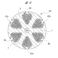
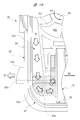
- FIG. 10 is a plan view showing the pump chamber side (cover member omitted) of the washer pump
- FIG. 11 is an enlarged view of a broken line circle C portion of FIG. 4
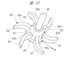
- FIG. 12 is a perspective view illustrating the detailed structure of the impeller. ing.
- an impeller 60 is fixed to one end of the armature shaft 44 in the axial direction so as to be integrally rotatable.
- the impeller 60 and the armature shaft 44 are fixed by so-called D-cut fitting so that they cannot be rotated relative to each other. That is, the impeller 60 is rotated by the motor 40.
- the impeller 60 includes an impeller body 61 fixed to the armature shaft 44, and a total of six blades 62 extending radially from the impeller body 61 and curved in a substantially crescent shape.
- hook-shaped protrusions formed in an arc shape with a predetermined radius of curvature R are formed on the armature core 43 side (the hook-shaped recess 32 d side) of the six blades 62 along the axial direction of the armature shaft 44. 62a is formed.
- These bowl-shaped convex parts 62a are provided along the bowl-shaped concave part 32d forming the pump chamber 32a.
- the radius of curvature of the bowl-shaped recess 32d that forms the pump housing portion 32 is also R, whereby the impeller 60 faces the bowl-shaped recess 32d with a predetermined gap therebetween.
- annular flange portion 63 bulging outward in the radial direction of the impeller body 61 is formed.
- the flange portion 63 is disposed downstream of the impeller body 61 along the flow direction of the cleaning liquid W (broken arrow in FIG. 12). As a result, as indicated by the broken-line arrows in FIG. 12, the flowing direction of the cleaning liquid W is quickly directed toward the tip side of each blade 62 to improve the pump capacity.
- the pump housing portion 32 includes a pump chamber 32a and a cleaning liquid inflow hole 32b provided on the upstream side (washer tank 10 side) of the pump chamber 32a.
- the cleaning liquid inflow hole 32b is formed inside the suction pipe 32c inserted into the insertion hole 15 of the washer tank 10 (see FIG. 1).
- the flow path area of the cleaning liquid inflow hole 32b gradually decreases from the washer tank 10 side toward the pump chamber 32a side. As a result, the flow rate of the cleaning liquid W sucked into the cleaning liquid inflow hole 32b is increased so that it can be efficiently sucked into the pump chamber 32a.
- the pump chamber 32a is formed in a flat shape in which the impeller 60 can be rotatably accommodated through a predetermined gap, and has a bowl-shaped recess 32d in which the radius of curvature is set to R.
- the opening part of the pump chamber 32a and each valve chamber 33a, 33b forms the 2nd opening part 30a of the housing 30, and the said 2nd opening part 30a is obstruct
- the second opening 30a is also formed on the side of the breathing hole 80 described later of the housing 30.
- the part with the breathing hole 80 of the 2nd opening part 30a is also obstruct
- the cover member CV is formed in a substantially flat plate shape from a resin material such as plastic and is firmly fixed to the housing 30 by ultrasonic welding or the like.
- an armature shaft 44 is disposed across the downstream side (pump chamber 32a side) of the cleaning liquid inflow hole 32b. Therefore, a lip seal LS made of rubber or the like is provided between the cleaning liquid inflow hole 32 b and the armature shaft 44. Thereby, the cleaning liquid W flowing through the cleaning liquid inflow hole 32b is prevented from leaking into the motor chamber 31a.
- the impeller 60 is also rotated in the forward / reverse direction inside the pump chamber 32a. At this time, regardless of the rotation direction of the impeller 60, the cleaning liquid W flowing through the cleaning liquid inflow hole 32b is sucked into the pump chamber 32a.
- FIGS. 13A and 13B are sectional views for explaining the position of the discharge hole with respect to the opening of the valve chamber
- FIGS. 14A and 14B are perspective views showing the valve unit
- FIG. Sectional views taken along line DD in (a) are respectively shown.
- the valve body accommodating portion 33 includes a front side valve chamber (valve chamber) 33 a and a rear side disposed on the opposite side of the pump chamber 32 a from the cleaning liquid inflow hole 32 b side.
- a valve chamber (valve chamber) 33b is provided. That is, the cleaning liquid W discharged from the pump chamber 32a flows into the pair of valve chambers 33a and 33b.
- the valve body accommodating portion 33 is integrally provided with a front side discharge pipe 33c corresponding to the front side valve chamber 33a, and a rear side discharge pipe 33d is integrally provided corresponding to the rear side valve chamber 33b. ing.
- the cleaning liquid W that has flowed into the front side valve chamber 33a flows out through the valve unit 70 into the front side discharge hole 33e inside the front side discharge pipe 33c.
- the cleaning liquid W that has flowed into the rear side valve chamber 33b flows through the valve unit 70 into the rear side discharge hole 33f inside the rear side discharge pipe 33d.
- the front side discharge hole 33e and the rear side discharge hole 33f constitute a pair of discharge holes in the present invention.
- a front-side flow path 34 is provided between the pump chamber 32a and the front-side valve chamber 33a. Further, a rear-side flow path 35 is provided between the pump chamber 32a and the rear-side valve chamber 33b.
- the motor housing portion 31, the pump chamber 32a, the pair of valve chambers 33a and 33b, the pair of discharge holes 33e and 33f, and the pair of flow paths 34 and 35 are integrally provided in one housing 30, respectively. .
- the cleaning liquid W flows into the valve chambers 33a and 33b depending on the rotation direction of the impeller 60.
- the cleaning liquid W flows from the pump chamber 32a toward the front side flow path 34 by rotating the impeller 60 counterclockwise.
- the cleaning liquid W flows from the pump chamber 32a toward the rear-side flow path 35 by rotating the impeller 60 in the clockwise direction.
- the motor 40 by forming each blade 62 of the impeller 60 in a substantially crescent shape, the motor 40 (see FIG. 4) flows out to the front-side flow path 34 when the rotational speed of the motor 40 (see FIG. 4) is the same rotational speed.
- the flow rate of the cleaning liquid W is larger than that of the cleaning liquid W flowing out to the rear side flow path 35. This is because it is necessary to increase the spray pressure of the cleaning liquid W because the front side receives traveling wind as compared with the rear side. That is, in the washer pump 20 of the present embodiment, the spray position of the cleaning liquid W with respect to the windshield (cleaning surface) on the front side can be made substantially constant regardless of the traveling wind.
- the front side valve chamber 33a side and the rear side valve chamber 33b side are respectively the front side discharge holes 33e. And it extends to the position of the rear side discharge hole 33f.
- the cross-hatched areas in FIG. 10 are the front-side channel 34 and the rear-side channel 35.
- the front side valve chamber 33a and the rear side valve chamber 33b are respectively provided with curved wall portions 33g. These curved wall portions 33g are formed in front of the outlet portions of the front-side channel 34 and the rear-side channel 35, and the cleaning liquid W discharged from the front-side channel 34 and the rear-side channel 35 is respectively curved walls. Rectification is performed along the portion 33g. Thus, the rapid diffusion of the cleaning liquid W into the valve chambers 33a and 33b is suppressed, and the cleaning liquid W is rectified in the valve chambers 33a and 33b, so that the cleaning liquid W is within the valve chambers 33a and 33b. Turbulence is suppressed.
- the shape of the front channel 34 and the shape of the rear channel 35 are different from each other.
- the cross-sectional shape in the direction intersecting the longitudinal direction of each flow path 34, 35 is formed in a substantially rectangular shape, and the depth dimensions of each flow path 34, 35 are the same.
- the front side flow path 34 constitutes one flow path in the present invention
- the rear side flow path 35 constitutes the other flow path in the present invention.
- the flow passage area on the pump chamber 32a side along the longitudinal direction of the front flow passage 34 is set to be smaller than the flow passage area on the front valve chamber 33a side along the longitudinal direction of the front flow passage 34.
- the outer wall portion 34 a disposed on the outer side (left side in the drawing) of the front-side channel 34 is provided near the side wall 30 b of the housing 30 and in parallel with the side wall 30 b.
- the inner side wall portion 34b disposed inside the front side flow path 34 (right side in the drawing) is provided on the inner side of the housing 30 than the side wall 30b of the housing 30, and is inclined with respect to the side wall 30b.
- the inner wall portion 34b gradually increases the flow passage area from the pump chamber 32a side of the front side flow passage 34 toward the front side valve chamber 33a side. That is, the inner wall part 34b constitutes an inclined wall in the present invention.
- the outer side wall part 34a is facing the inner side wall part 34b, and comprises the opposing wall in this invention.
- the pump chamber 32a side along the longitudinal direction of the front side flow path 34 is narrowed, and the flow rate of the cleaning liquid W flowing out from the pump chamber 32a to the front side flow path 34 is increased. Therefore, the flow of the cleaning liquid W into the front side valve chamber 33a is made smooth, and the subsequent rapid diffusion of the cleaning liquid W into the front side valve chamber 33a is suppressed.
- the front side flow path 34 is provided corresponding to the injection of the cleaning liquid W to the windshield on the front side of the vehicle. That is, the washer pump 20 according to the present embodiment employs a structure suitable for application to the front side where the injection pressure of the cleaning liquid W needs to be increased.
- the spray pressure of the cleaning liquid W on the rear side does not need to be increased as much as the spray pressure of the cleaning liquid W on the front side. Therefore, giving priority to the ease of manufacture of the housing 30, the flow area on the pump chamber 32 a side along the longitudinal direction of the rear side flow path 35 and the rear side valve chamber along the longitudinal direction of the rear side flow path 35.
- the channel area on the 33b side is the same channel area.
- the outer wall portion 35a is disposed outside the rear side flow path 35 (right side in the figure), and is disposed inside the rear side flow path 35 (left side in the figure).
- the inner wall portions 35 b are parallel to each other, and both are parallel to the side wall 30 b of the housing 30.
- the flow passage area of the front side flow passage 34 on the pump chamber 32a side is set smaller than the flow passage area of the rear side flow passage 35 on the pump chamber 32a side.
- the flow area on the front valve chamber 33a side of the front flow path 34 is set larger than the flow area on the rear valve chamber 33b side of the rear flow path 35.
- the length of the inner wall portion 34b from the front side valve chamber 33a to the pump chamber 32a is longer than the length of the inner wall portion 35b from the rear side valve chamber 33b to the pump chamber 32a.
- the pump capacity is changed according to the rotation of the motor 40 in the forward direction or the reverse direction, and the shapes of the front side flow path 34 and the rear side flow path 35 are changed.
- the passage 34 has a larger flow rate and higher flow rate of the cleaning liquid W than the rear side passage 35.
- a chamber 36 is provided.
- a diaphragm type valve unit 70 is mounted in the valve storage chamber 36. That is, the valve unit 70 partitions the pair of valve chambers 33a and 33b.
- the valve main body 71b (refer FIG. 15) of the switching valve 71 which comprises the valve unit 70 is arrange
- a front-side discharge hole 33e and a rear-side discharge hole 33f are disposed on both sides of the switching valve 71 in the moving direction of the valve body 71b.
- the valve body 71b of the switching valve 71 has a high internal pressure in the front-side valve chamber 33a. Then, the front discharge pipe 33c is opened and the rear discharge pipe 33d is closed. As a result, the cleaning liquid W flows only through the front discharge holes 33e and is then sprayed toward the windshield on the front side.
- the valve main body 71b of the switching valve 71 opens the rear side discharge pipe 33d and closes the front side discharge pipe 33c when the internal pressure of the rear side valve chamber 33b increases. As a result, the cleaning liquid W flows only through the rear-side discharge hole 33f and is then sprayed toward the rear-side windshield.
- valve unit 70 is mounted in the valve storage chamber 36 in a predetermined direction. That is, the valve unit 70 has an assembling direction with respect to the valve housing chamber 36.
- a front side discharge hole 33e is opened in the front side valve chamber 33a, and one side surface 70a (FIG. 15) of the valve unit 70 is formed around the front side discharge hole 33e. 1st opposing surface 36a with which a reference) is opposed is provided.
- a pair of rectifying the cleaning liquid W flowing in the front side valve chamber 33a toward the front side discharge hole 33e that is, the center of the valve main body 71b.
- the curved portion 36b is provided.
- a rear side discharge hole 33f is opened in the rear side valve chamber 33b, and the other side surface 70b (FIG. 15) of the valve unit 70 is formed around the rear side discharge hole 33f.
- a second facing surface 36c is provided to face the other.
- a pair of rectifying the cleaning liquid W flowing in the rear side valve chamber 33b toward the rear side discharge hole 33f that is, the center of the valve body 71b.
- the curved portion 36d is provided.
- the second opposing surface 36c is provided with a pair of recesses (concave portions) 36e into which the misassembly prevention protrusions 72c (see FIG. 15) provided on the other side surface 70b of the valve unit 70 enter and are engaged. ing.
- These hollow portions 36e are recessed toward the rear side discharge pipe 33d (see FIG. 10). In other words, each recess 36e is provided to be recessed on one side in the moving direction of the valve body 71b.
- the hollow part 36e is not provided in the front side valve chamber 33a side (refer Fig.13 (a)). That is, in the state where one side surface 70a of the valve unit 70 is opposed to the second opposing surface 36c and the other side surface 70b of the valve unit 70 is opposed to the first opposing surface 36a, there is no place for the misassembly prevention protrusion 72c. . Therefore, the valve unit 70 protrudes from the valve accommodating chamber 36 and is in a state where it is not correctly assembled, that is, an “incorrectly assembled state”.
- the erroneous assembly prevention mechanism including the recessed portion 36 e and each misassembly prevention protrusion 72 c causes the valve unit 70 to protrude from the valve storage chamber 36.
- the assembly operator or the like easily grasp (notify) the “erroneous assembly state” in appearance.
- the distance between the center portion of the front side discharge hole 33e and the rear side discharge hole 33f and the lower end portion 30c on the second opening 30a side of the housing 30 is set to H. Yes.
- This distance H is larger than the diameter D (see FIG. 2) of the thickest portions of the front discharge pipe 33c and the rear discharge pipe 33d (H> D).
- the discharge pipes 33c and 33d are arranged on the motor accommodating portion 31 side (upper side in the drawing) with respect to the lower end portion 30c of the housing 30, respectively. Specifically, as shown in FIG.
- the pair of discharge holes 33e and 33f are closer to the motor chamber 31a than the lower end in the axial direction of the motor 40 of the suction pipe 32c and from the upper end in the axial direction of the motor 40 of the suction pipe 32c. It is provided near the cover member CV. Thereby, the axial height of the motor 40 in the washer pump 20 can be reduced. Therefore, it is possible to reduce the size and weight of the washer pump 20 while suppressing the shape of the washer pump 20 from becoming complicated.
- the valve unit 70 is formed in a substantially square plate shape.
- the valve unit 70 includes a switching valve (valve element) 71 formed of a thin rubber material or the like, and a frame body 72 that is attached to the switching valve 71 and reinforces the switching valve 71.
- the frame body 72 is shaded to clearly distinguish the switching valve 71 and the frame body 72.
- the switching valve 71 includes a mounting portion 71a formed in a substantially square shape (rectangular shape) when viewed from the moving direction of the valve body 71b.
- the mounting portion 71a is mounted in the valve storage chamber 36 (see FIG. 10).
- the mounting portion 71a of the switching valve 71 is also mounted inside the cover member-side housing portion CM (see FIG. 3) provided in the cover member CV.
- the mounting portion 71 a has a substantially U-shaped cross section, and a part of the main body 72 a of the frame 72 is mounted inside the mounting portion 71 a. That is, the main body portion 72a supports the mounting portion 71a, whereby the mounting portion 71a is reinforced by the main body portion 72a, and the mounting portion 71a is deformed when the mounting portion 71a is mounted to the valve storage chamber 36 or the like. It is prevented from tilting or tilting.
- a valve body 71b formed in a substantially disc shape is provided on the radially inner side of the mounting portion 71a.
- the valve body 71b is moved in the extending direction of the discharge pipes 33c and 33d according to the internal pressure of the valve chambers 33a and 33b. Thereby, the front side discharge pipe 33c and the rear side discharge pipe 33d are opened and closed by the both sides in the thickness direction of the valve body 71b.
- an annular thin portion 71c that is deformed when the valve main body 71b is moved is provided between the valve main body 71b and the mounting portion 71a. And as shown in FIG. 15, the thin part 71c is made thinner than the valve main body 71b, and the cross section is a bending shape. Accordingly, the discharge pipes 33c and 33d can be reliably opened and closed while facilitating the movement of the valve main body 71b.
- the frame body 72 is formed of a plastic having a higher rigidity than that of the switching valve 71, and thus the mounting portion 71a of the switching valve 71 can be sufficiently reinforced.
- the frame body 72 includes a main body portion 72a formed in a substantially square shape (square shape) when viewed from the moving direction of the valve main body 71b, and a part of the main body portion 72a is mounted inside the mounting portion 71a.
- a circular hole 72b that is set to have an inner diameter that is substantially the same as the outer diameter of the thin portion 71c of the switching valve 71 is provided on the radially inner side of the main body 72a. Thereby, the valve main body 71b can move inside the radial direction of the circular hole 72b without being obstructed by the frame body 72.
- the misassembly prevention protrusion (convex part) 72c is provided in each of the four corners of the main body 72a. These misassembly prevention protrusions 72c protrude from the other side surface 70b of the valve unit 70, as shown in FIG. That is, each misassembly prevention protrusion 72c is provided to protrude to one side in the movement direction of the valve body 71b.
- the outer side of the misassembly preventing projection 72c along the radial direction of the frame body 72 is engaged with the inner side of the recess 36e along the radial direction of the frame body 72. In the case of the relationship, the valve unit 70 does not protrude from the valve storage chamber 36 and is in a correctly assembled state.
- each misassembly prevention protrusion 72c provided at the four corners of the main body 72a are disposed on the radially outer side of the circular hole 72b, and do not hinder the movement of the valve main body 71b.
- each misassembly prevention protrusion 72c is provided in the dead space of the main body 72a.
- the frame body 72 cannot be assembled to the switching valve 71 such that each misassembly prevention protrusion 72c faces the thin portion 71c.
- each misassembly prevention protrusion 72c has a function of preventing misassembly of the valve unit 70 itself.
- the misassembly prevention protrusion 72c is formed in a substantially triangular shape in plan view, and includes a circular hole 72b, that is, an inclined surface 72d that gradually falls toward the center of the valve body 71b.
- each misassembly prevention protrusion 72c is exposed at four corners (not shown) in the rear side valve chamber 33b under the state where the valve unit 70 is mounted in the valve storage chamber 36. Therefore, by providing the inclined surface 72d on each misassembly prevention protrusion 72c, the rectifying effect of the cleaning liquid W flowing in the rear valve chamber 33b is not lowered.
- each inclined surface 72d serves to direct the direction of the cleaning liquid W flowing in the rear valve chamber 33b toward the valve body 71b.
- the inclined surface 72d formed on the recess 36e side along the moving direction of the valve body 71b guides the flow of the cleaning liquid W toward the center of the valve body 71b.
- the hardness of the movement differs depending on the movement direction of the valve main body 71b. That is, the valve main body 71b is hard to move in the direction of the solid line arrow M1 (upward in the figure) and soft to move in the direction of the broken line arrow M2 (downward in the figure). More specifically, the movement or deformation of the thin portion 71c is obstructed by the main body portion 72a when moving in the direction of the solid line arrow M1, but when moving in the direction of the broken line arrow M2, the thin portion 71c is moved. The movement or deformation is not hindered by the main body 72a. Thereby, the hardness of the movement differs depending on the moving direction of the valve main body 71b.
- the movement of the valve body 71b in the hard direction is the front side, and the movement of the valve body 71b in the soft direction is the rear side.
- the cleaning liquid W can be sprayed onto the rear side windshield with a weak injection pressure, and the wide area of the rear side windshield can be evenly wetted with the cleaning liquid W.
- the injection pressure of the cleaning liquid W is optimized between the front side and the rear side by providing a difference in the injection pressure of the cleaning liquid W between the front side and the rear side.
- the valve unit 70 has an assembling directionality. Therefore, by providing four misassembly prevention protrusions 72c on the valve unit 70 side and a pair of recesses 36e on the rear side valve chamber 33b side, the washer pump 20 is prevented from being assembled incorrectly. . That is, by providing a misassembly prevention mechanism including the recess 36e and the misassembly prevention protrusion 72c between the housing 30 and the frame body 72, the yield in the assembly process of the washer pump 20 is improved.
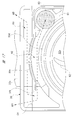
- FIG. 16 is a sectional view of the housing along the line EE in FIG. 10
- FIG. 17 is a partially enlarged view of the broken line circle F portion of FIG. 10, and FIG. Respectively.
- the motor housing portion 31 formed in a substantially cylindrical shape is held by a pair of tank side holding portions 14 provided in the washer tank 10, whereby the washer pump 20 is attached to the washer tank 10. Wearing. Accordingly, a substantially triangular dead space DS is formed between the washer tank 10 having a flat surface and the motor housing portion 31 having an arc surface as shown by a broken-line circle in FIG. A corner portion 32e is provided at a portion of the pump housing portion 32 corresponding to the dead space DS. That is, the corner portion 32 e is disposed in the housing 30 between the motor housing portion 31 and the washer tank 10 in a state where the washer pump 20 is mounted on the washer tank 10.
- a breathing hole 80 that communicates the inside and outside of the motor housing 31 is provided between the motor housing 31 and the corner 32 e. More specifically, one end side (lower side in FIG. 16) of the breathing hole 80 is opened inside the motor housing portion 31, and the other end side (upper side in FIG. 16) of the breathing hole 80 is a corner portion. Opened in the interior of 32e. Thus, the breathing hole 80 communicates between the motor chamber 31 a in the motor housing 31 and the outside of the housing 30. The breathing hole 80 is disposed in the corner portion 32e in the dead space DS (see FIG. 2) of the pump housing portion 32, but does not communicate with the pump chamber 32a.
- the breathing hole 80 penetrates in the axial direction of the motor accommodating portion 31 and is formed in a step shape as shown in the partial enlarged view in the broken line circle of FIG. As a result, air is formed between the corner portion 32e (outside of the housing 30) outside the motor housing portion 31 and in the dead space DS of the pump housing portion 32, and the motor chamber 31a in the motor housing portion 31. (AIR) can come and go.
- the breathing hole 80 is disposed in the corner portion 32e of the housing 30 that can be the dead space DS as described above.
- the housing 30 does not become unnecessarily large and a sufficient breathing function can be provided.
- the breathing hole 80 can be disposed within the outer region including the washer pump 20 and the washer tank 10 with the washer pump 20 mounted on the washer tank 10.
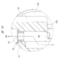
- a porous filter 81 that restricts the passage of water while allowing the passage of air.
- the porous filter 81 is provided so as to close the breathing hole 80 and is fixed to the inside of the corner portion 32e (housing 30) by ultrasonic welding or the like on the outer peripheral portion thereof.
- the inner side of the corner 32e of the porous filter 81 is not limited to ultrasonic welding, and a double-sided tape, an adhesive, or the like may be used.
- each discharge pipe 33 c is provided on the radially outer side of the pump chamber 32 a in the housing 30 and on the upstream side of the porous filter 81 provided in the breathing hole 80 (outside of the housing 30).
- 33d is provided with a first air passage 82 over substantially the entire width direction of the housing 30 along the extending direction. That is, the first air passage 82 is provided so as to extend in the width direction of the housing 30 intersecting the suction direction of the cleaning liquid W (up and down direction in FIG. 17), and one end side (right side in the figure) of the first air passage 82 is provided. The other end side of the breathing hole 80 is communicated.
- the first ventilation path 82 includes an arc wall 30d of the housing 30 that forms the pump chamber 32a, an outer wall 30e of the housing 30 that is provided radially outside the arc wall 30d, and a cover member CV (see FIG. 3). It is formed between. That is, a part of the inside of the corner portion 32e, the porous filter 81 provided inside the corner portion 32e so as to close the breathing hole 80, and the first air passage 82 are respectively in the housing 30. 2 Covered by a cover member CV that closes the opening 30a. Accordingly, the breathing hole 80, the porous filter 81, and the first air passage 82 cannot be viewed from the axial direction of the armature shaft 44, and are hidden by the cover member CV (see FIG. 3).
- a cutout portion 30f formed by cutting out a part of the outer wall 30e is disposed on the other side in the width direction of the housing 30 that intersects the suction direction of the cleaning liquid W (left side in FIG. 17).
- air (AIR) flows back and forth between the outside of the housing 30 and the breathing hole 80 via the first air passage 82 as indicated by the broken-line arrows in the drawing. That is, the breathing hole 80 (porous filter 81) is disposed in a deep part covered with the cover member CV along the width direction of the housing 30.
- the outside of the housing 30 and the porous filter 81 are separated from each other. This makes it difficult for rainwater, dust, etc. to reach the porous filter 81. Therefore, a sufficient respiratory function can be maintained over a long period of time, and the life of the washer pump 20 can be extended.
- the second ventilation path 83 is provided further upstream of the first ventilation path 82.
- the second ventilation path 83 is connected to the first ventilation path 82 at the corner 32e on the opposite side of the breathing hole 80 from the suction pipe 32c. ing.
- the second ventilation path 83 is formed so as to be folded back to the first ventilation path 82, and one end side thereof communicates with the other end side of the first ventilation path 82 via a notch 30 f. Similar to the first ventilation path 82, the second ventilation path 83 is provided over substantially the entire width direction of the housing 30 that intersects the suction direction of the cleaning liquid W.
- the second ventilation path 83 is not blocked by the cover member CV, and as shown in FIGS. 3 and 17, the entire width direction of the housing 30 intersects the suction direction of the cleaning liquid W in the second ventilation path 83. Is open. That is, a part of the inside of the corner portion 32e is covered with the cover member CV. As a result, even if the washer pump 20 is submerged, the second air passage 83 is elongated and has a large opening, making it difficult to form a water film or the like. Inhibition is effectively suppressed.
- a filter member 90 as shown in FIG. 18 may be detachably provided in the breathing hole 80 instead of the porous filter 81 fixed inside the corner portion 32e by ultrasonic welding or the like.
- the filter member 90 can be periodically replaced, and the maintainability of the washer pump 20 can be improved.
- the filter member 90 includes a tube material 91 made of rubber or the like, and a porous filter 92 fixed to one side in the axial direction (upper side in the drawing) of the tube material 91 by ultrasonic welding or the like. .
- FIG. 19 is an explanatory diagram for explaining the flow of the cleaning liquid on the front side
- FIG. 20 is an explanatory diagram for explaining the flow of the cleaning liquid on the rear side.
- the pumping capacity is higher than that when the impeller 60 is rotated in the clockwise direction. Increased as indicated by the solid solid arrows. Further, the flow rate of the cleaning liquid W flowing through the front side flow path 34 is higher than that of the cleaning liquid W flowing through the rear side flow path 35.
- the cleaning liquid W having a high flow rate flowing through the front side flow path 34 is discharged into the front side valve chamber 33a (shaded portion in the figure).
- the flow rate of the cleaning liquid W is high, and the cleaning liquid W is discharged into the front side valve chamber 33a at the front side discharge hole 33e. Therefore, the cleaning liquid W does not become a turbulent flow in the front side valve chamber 33a. Therefore, the cleaning liquid W discharged into the front valve chamber 33a is smoothly collected toward the center of the valve unit 70, that is, the valve body 71b of the switching valve 71.
- the internal pressure of the front side valve chamber 33a is increased, the valve main body 71b is moved in the direction shown by the solid arrow M1 in FIGS. 15 and 19, and the front side discharge hole 33e is opened. Thereafter, the cleaning liquid W is jetted vigorously toward a predetermined launch point of the windshield on the front side. At this time, the rear side discharge hole 33f of the rear side discharge pipe 33d is closed by the valve body 71b.
- the pumping capacity is lower than that when the impeller 60 is rotated in the counterclockwise direction. As shown by the outlined broken arrow, there are few. Further, the flow rate of the cleaning liquid W flowing through the rear side flow path 35 is slower than that of the cleaning liquid W flowing through the front side flow path 34.
- the cleaning liquid W that has flowed through the rear-side flow path 35 is discharged into the rear-side valve chamber 33b (shaded portion in the figure).
- the cleaning liquid W is discharged into the rear side valve chamber 33b at the portion of the rear side discharge hole 33f, and the cleaning liquid W is rectified following the curved wall portion 33g immediately after being discharged into the rear side valve chamber 33b.
- the cleaning liquid W does not become turbulent in the rear side valve chamber 33b. Therefore, the cleaning liquid W discharged into the rear side valve chamber 33 b is smoothly collected toward the center of the valve unit 70, that is, toward the valve body 71 b of the switching valve 71.
- the pump chamber 32a, the valve chambers 33a and 33b, the discharge holes 33e and 33f, and the flow paths 34 and 35 are integrated with the housing 30, respectively. Therefore, when these are formed as separate members, there is no need to form a step or the like that obstructs the flow of the cleaning liquid W in the path through which the cleaning liquid W flows, so that the pressure loss of the cleaning liquid W can be reduced. it can.
- each valve chamber 33a, 33b side of each flow path 34, 35 is extended to the position of each discharge hole 33e, 33f, the washing
- the flow area on the pump chamber 32a side of the front flow path 34 is smaller than the flow area on the front valve chamber 33a side.
- the flow rate of the cleaning liquid W flowing through the passage 34 can be increased, the flow of the cleaning liquid W into the front side valve chamber 33a can be made smooth, and the subsequent rapid diffusion of the cleaning liquid W into the front side valve chamber 33a can be suppressed. Therefore, the turbulent flow of the cleaning liquid W inside each valve chamber 33a, 33b can be suppressed more reliably.
- the front side flow path 34 includes the inner wall portion 34b that gradually increases the flow path area from the pump chamber 32a side to the front side valve chamber 33a side. Therefore, the flow passage area of the front flow passage 34 can be changed linearly from the pump chamber 32a side to the front valve chamber 33a side. Therefore, the turbulent flow in the front side flow path 34 can be suppressed more reliably, and the highly efficient washer pump 20 with less pressure loss can be realized.
- the front-side flow path 34 has the outer wall part 34 a that faces the inner wall part 34 b, and the outer wall part 34 a is closer to the side wall 30 b of the housing 30. Since the inner wall portion 34b is provided in parallel to the side wall 30b and is provided on the inner side of the side wall 30b of the housing 30, the housing 30 is not increased in size, and the inside of the housing 30 is provided from the pump chamber 32a side. A front-side channel 34 whose channel area gradually increases toward the front-side valve chamber 33a can be formed. Therefore, the dedicated design of the cover member CV is not required, and the cost increase can be suppressed.
- the flow area on the pump chamber side of the front side flow path 34 is smaller than the flow area on the pump chamber 32a side of the rear side flow path 35.
- the pump capacity can be varied according to the rotation of the motor 40 in the forward direction or the reverse direction.
- the front-side flow path 34 is provided corresponding to the injection of the cleaning liquid W to the windshield on the front side of the vehicle, the position of the cleaning liquid W to be injected with respect to the front-side windshield affected by the traveling wind is set. It can be made almost constant regardless of the running wind. That is, the cleaning performance of the washer pump 20 can be improved.
- the housing 30 has a motor accommodating portion 31 for accommodating the motor 40, a corner portion 32e disposed between the motor accommodating portion 31 and the washer tank 10, and And a breathing hole 80 communicating between the inside and outside of the motor housing 31 is provided between the motor housing 31 and the corner 32e. Accordingly, the breathing hole 80 can be disposed within the outer region including the washer pump 20 and the washer tank 10 with the washer pump 20 mounted on the washer tank 10. Therefore, it is possible to prevent the respiratory structure from being damaged at the time of installation or the like, and the conventional member for the respiratory structure is not necessary, and it is possible to further reduce the size and weight.
- one end side of the breathing hole 80 is opened inside the motor accommodating portion 31, and the other end side of the breathing hole 80 is opened inside the corner portion 32e.
- the interior of the corner 32e communicates with the outside, and a part thereof is covered with a cover member CV that closes the second opening 30a formed on the breathing hole 80 side of the housing 30.
- the breathing hole 80 is provided with the porous filter 81 that restricts the passage of water while permitting the passage of air. It is possible to reliably prevent rainwater and the like from entering.
- the porous filter 81 is provided inside the corner portion 32e and closes the second opening 30a formed on the breathing hole 80 side of the housing 30. Since it is covered with the cover member CV, it is possible to make rainwater or the like difficult to reach the porous filter 81. Therefore, the porous filter 81 can be kept clean for a long period of time, and the maintenance cycle can be extended.
- one end side of the breathing hole 80 is opened inside the motor housing part 31, and the other end side of the breathing hole 80 is opened inside the corner part 32e.
- the first air passage 82 communicating with the other end side of the breathing hole 80 is provided, and the first air passage 82 is covered with the cover member CV that closes the housing 30. It can be made more difficult to reach rainwater or the like.
- the washer pump 20 since the first ventilation path 82 extends in the width direction of the housing 30 intersecting the suction direction of the cleaning liquid W, the distance of the first ventilation path 82 The rain filter or the like can be made harder to reach the porous filter 81.
- one end side of the first air passage 82 is communicated with the breathing hole 80, and the other end side of the first air passage 82 is provided in the housing 30.
- the second air passage 83 communicates with the air passage 83 and extends in the width direction of the housing 30 and is not covered with the cover member CV.
- a membrane or the like can be made difficult, and rainwater or the like can be made harder to reach the porous filter 81.
- valve unit 70 protrudes from the housing 30 between the housing 30 and the frame body 72, so that the valve unit 70 can be removed from the housing 30.
- An erroneous assembly prevention mechanism is provided which includes a recess 36e for notifying erroneous assembly and an erroneous assembly prevention protrusion 72c.
- valve unit 70 when the valve unit 70 is erroneously assembled to the housing 30, the valve unit 70 protrudes from the housing 30, and the cover member CV that closes the housing 30 cannot be attached to the housing 30. That is, it is possible to prevent the washer pump 20 from being physically assembled and to prevent erroneous assembly of the valve unit 70 to the housing 30. Therefore, the yield of the washer pump 20 can be improved and the reliability of the product can be improved.
- the misassembly prevention mechanism is provided in the housing 30 and has a hollow portion 36e that is depressed on one side in the moving direction of the valve body 71b (switching valve 71), and a frame. It is formed from a misassembly prevention protrusion 72c provided on the body 72 and protruding to one side in the moving direction of the valve main body 71b and engaged with the recess 36e. Therefore, an assembly operator or the like can easily check the dent 36e and the erroneous assembly prevention protrusion 72c by visual observation, and can more reliably prevent erroneous assembly of the valve unit 70 to the housing 30. It becomes.
- the frame body 72 is formed in a square shape when viewed from the moving direction of the valve body 71 b, and the misassembly prevention protrusions 72 c are provided at the four corners of the frame body 72.
- the outer side of the misassembly prevention protrusion 72 c along the radial direction of the frame body 72 is engaged with the inner side of the recessed portion 36 e along the radial direction of the frame body 72. Therefore, the center position of the valve main body 71b and the center positions of the front side discharge pipe 33c and the rear side discharge pipe 33d can be accurately positioned without deviation.
- valve opening characteristics / valve closing characteristics the movement characteristics of the valve main body 71b for each product.
- misassembly prevention protrusions 72 c are provided at the four corners of the frame body 72, any of the four sides formed by the outer periphery of the mounting portion 71 a of the switching valve 71 when the valve unit 70 is assembled to the housing 30. Can be inserted even when facing the housing 30 side, and the insertion direction of the valve unit 70 is not limited.
- the flow of the cleaning liquid W is directed to the center of the switching valve 71 (valve) on the side of the depression 36e along the moving direction of the valve body 71b.
- An inclined surface 72d is formed for guiding toward the main body 71b).
- the rigidity of the frame 72 is higher than the rigidity of the switching valve 71, so that the valve unit 70 is forcibly mistakenly assembled to the housing 30. Can be prevented in advance, and erroneous assembly of the valve unit 70 to the housing 30 can be prevented more reliably.
- the motor chamber 31a, the pump chamber 32a, the valve chambers 33a and 33b, and the discharge holes 33e and 33f are integrally provided in the housing 30, respectively.
- the motor 40 includes the yoke 41 fixed inside the motor chamber 31a, the two magnets 42 fixed inside the yoke 41, and the armature shaft 44.
- a fixed commutator 45 having six segments 45a, an armature core 43 fixed to the armature shaft 44, and having six slots 43a around which the coil 46 is wound by lap winding, and rotated inside the magnet 42; It is equipped with.
- the coil 46 can be easily attached to the armature core 43 by the winding operation three times by the double flyer method. Further, compared to a motor that uses one ring-shaped magnet, by using two divided magnets, it is possible to improve the layout when fixing the magnet, in addition to miniaturization of the magnet. Therefore, it is possible to cope with the reduction in size and weight of the motor 40 while suppressing the manufacturing cost.
- the motor 40 includes the power supply brush 54 that is slidably contacted with the commutator 45, and the holding plate 53 that holds the power supply brush 54 with the brush holding portion 53b.
- Two bent portions 53 c are provided near the base end portion 53 a of the holding plate 53.
- the movable range of the holding plate 53 can be expanded, and the power supply brush 54 can be brought into sliding contact with the commutator 45 with an optimal pressing force. Further, since the power supply brush 54 can be used up to the end, the size of the power supply brush 54 can be reduced, and the power supply brush 54 can be easily arranged in a space-saving manner.
- the motor chamber 31a is closed by the motor cover 50, and the connector connecting portion 52 to which the power supply connector is connected is provided outside the motor cover 50.
- a rib 55 is provided inside the motor cover 50, and a base end portion 53 a of the holding plate 53 is attached.
- the cover body 51 can obtain sufficient strength.
- the connector connection part 52 is integrated and the base end part 53a of the holding plate 53 is firmly fixed. Can withstand enough.
- the impeller 60 is provided with the hook-shaped convex portion 62a, and the pump chamber 32a has the hook-shaped concave portion along the hook-shaped convex portion 62a of the impeller 60. 32d is provided.
- the washer pump 20 can be further reduced in size and weight.
- the washer pump 20 can be attached to the washer tank to which the old washer pump (large size) is attached while reinforcing the motor accommodation part 31 in correspondence with the miniaturization of the motor accommodation part 31. . That is, for example, in the maintenance of the washer device, the washer pump 20 can be simply used instead of the old washer pump.
- the pair of discharge holes 33e and 33f are provided closer to the motor chamber 31a than the second openings 30a of the valve chambers 33a and 33b.
- the present invention is not limited to the above-described embodiment, and various modifications can be made without departing from the scope of the invention.
- the shape of the front side flow path 34 and the shape of the rear side flow path 35 are different from each other.
- the present invention is not limited to this, depending on the specifications of the washer pump 20 and the like.
- the front side channel and the rear side channel can also have the same shape.
- the inner wall portion 34b of the front side flow path 34 is an inclined wall, and the flow area of the front side flow path 34 is linearly changed.
- the inner wall portion 34b may be formed in a step shape according to the specifications of the washer pump 20, and the flow channel area of the front flow channel 34 may be changed stepwise.
- the washer pump 20 that injects the cleaning liquid W onto the windshields on the front side and the rear side of the vehicle is shown.
- the present invention is not limited to this, and for example, wiper blade wiper
- the present invention can also be applied to a washer pump that injects a cleaning liquid to each of the direction forward path side and the return path side.
- each component in the above embodiment is arbitrary as long as the present invention can be achieved, and are not limited to the above embodiment.
- the washer pump is used for sucking the cleaning liquid stored in the washer tank, spraying the cleaning liquid onto the windshield, and removing dirt such as dust adhering to the windshield.
Abstract
ポンプ室32a、各弁室33a,33b、各吐出孔33e,33fおよび各流路34,35がそれぞれハウジング30に一体に設けられているので、これらを別部材で形成した場合における、洗浄液Wの流れる経路に洗浄液Wの流れを阻害する段差等が形成されずに済むため、洗浄液Wの圧力損失を低減できる。各流路34,35の各弁室33a,33b側が各吐出孔33e,33fの位置まで延在されているので、各流路34,35から流れ出る洗浄液Wを、従前に比して各弁室33a,33bの中央寄りの部分で放出させることができる。よって、各流路34,35の出口部分と各吐出孔33e,33fの入口部分とを互いに近付けることができ、各弁室33a,33bの内部での洗浄液Wの乱流が抑えられて、圧力損失を低減できる。
Description
本発明は、タンクに貯留された液体を吸入し、液体を洗浄面に噴射するウォッシャポンプに関する。
従来、自動車等の車両のフロント側およびリヤ側には、それぞれウィンドシールドが設けられ、エンジンルーム内の所定箇所には、各ウィンドシールドを洗浄するためのウォッシャ装置が設置されている。ウォッシャ装置は、ウォッシャポンプと、液体(ウォッシャ液)を貯留するタンクとを備えている。ウォッシャポンプは、操作スイッチの操作により駆動され、モータの回転方向に応じてタンク内の液体を各ウィンドシールドにそれぞれ噴射する。そして、ウィンドシールドに噴射された液体を、ワイパ装置を駆動させてワイパブレードにより払拭させることで、ウィンドシールド(洗浄面)が綺麗に洗浄される。
タンクに貯留された液体を吸入し、液体を洗浄面に噴射するウォッシャポンプには、例えば、特許文献1に記載された技術がある。
特許文献1に記載されたウォッシャポンプは、インペラを収容する収容室(ポンプ室)と、インペラの回転方向により洗浄液(液体)がそれぞれ流入される第1,第2弁室(弁室)と、収容室と第1,第2弁室とをそれぞれ接続する第1,第2通路(流路)と、第1,第2弁室を互いに仕切る弁体(切替バルブ)と、弁体の移動方向両側に設けられる第1,第2液体管(吐出孔)と、を備えている。
しかしながら、上述の特許文献1に記載されたウォッシャポンプによれば、インペラの回転によりポンプ室から流路に向けて液体が流入し、流路に流入した液体は当該流路を勢い良く流れる。その後、流路を流れた液体は、弁室の端部から弁室の内部に勢い良く放出される。つまり、流路から放出された液体は、弁室の内部において急激に拡散されることになる。そして、弁室の内部に勢い良く放出された液体は、弁室の内部であらゆる方向に移動して乱流となる。具体的には、液体同士が互いに衝突するようなことが起こる。これにより、弁室の内部において液体の圧力損失が発生して当該液体の流れにロスが生じる。よって、ウォッシャポンプの噴射能力が低下する等の問題が発生し得る。
本発明の目的は、噴射能力が低下するのを抑制して、より小型軽量化を図ることが可能なウォッシャポンプを提供することにある。
本発明の一態様では、タンクに貯留された液体を吸入し、前記液体を洗浄面に噴射するウォッシャポンプであって、正逆方向に回転されるモータと、前記モータにより回転されるインペラと、前記インペラが収容されるポンプ室と、前記インペラの回転方向により前記液体がそれぞれ流入される一対の弁室と、前記一対の弁室を仕切る切替バルブと、前記切替バルブの移動方向両側に設けられる一対の吐出孔と、前記ポンプ室と前記一対の弁室との間にそれぞれ設けられる一対の流路と、を有し、前記ポンプ室、前記弁室、前記吐出孔および前記流路がそれぞれハウジングに一体に設けられ、前記流路の前記弁室側が前記吐出孔の位置まで延在されている。
本発明の他の態様では、前記一対の流路のうちの少なくとも何れか一方の流路の前記ポンプ室側の流路面積の方が前記弁室側の流路面積よりも小さい。
本発明の他の態様では、前記一方の流路は、前記ポンプ室側から前記弁室側に向けて流路面積を徐々に大きくさせる傾斜壁を備えている。
本発明の他の態様では、前記一方の流路は、前記傾斜壁と対向する対向壁を有し、前記対向壁は、前記ハウジングの側壁寄りに当該側壁と平行に設けられ、前記傾斜壁は、前記ハウジングの前記側壁よりも内側に設けられている。
本発明の他の態様では、前記一方の流路の前記ポンプ室側の流路面積の方が、前記一対の流路のうちの他方の流路の前記ポンプ室側の流路面積よりも小さい。
本発明の他の態様では、前記一方の流路は、車両のフロント側の前記洗浄面への前記液体の噴射に対応して設けられている。
本発明によれば、ポンプ室、弁室、吐出孔および流路がそれぞれハウジングに一体に設けられているので、これらを別部材で形成した場合における、液体の流れる経路に液体の流れを阻害する段差等が形成されずに済むため、液体の圧力損失を低減することができる。
また、流路の弁室側が吐出孔の位置まで延在されているので、流路から流れ出る液体を、従前に比して弁室の中央寄りの部分で放出させることができる。これにより、流路の出口部分と吐出孔の入口部分とを互いに近付けることができ、弁室の内部での液体の乱流が抑えられて、圧力損失を低減することができる。
したがって、噴射能力の低下が抑えられて、従前と同じ噴射能力のウォッシャポンプにおいて、低出力の小型モータを採用することができ、ウォッシャポンプのさらなる小型軽量化を実現できる。
以下、本発明の一実施の形態について図面を用いて詳細に説明する。
図1は本発明のウォッシャポンプのウォッシャタンクへの装着状態を説明する分解斜視図を示している。
図1に示すように、ウォッシャタンク(タンク)10は、白色かつ半透明のプラスチック材料等により中空の略直方体形状に形成され、その内部には、ウォッシャ液等の洗浄液(液体)Wが貯留されている。ウォッシャタンク10は、当該ウォッシャタンク10の外郭を形成するタンク壁12を備えており、タンク壁12の底部側(図中下側)には、ポンプ装着部13が一体に設けられている。ポンプ装着部13は、ウォッシャタンク10の内側に窪んで設けられ、ポンプ装着部13には、ウォッシャポンプ20のハウジング30を保持する一対のタンク側保持部14が設けられている。各タンク側保持部14は、ポンプ装着部13の一部を、その径方向内側に突出させることにより設けられ、各タンク側保持部14同士の離間寸法はW1に設定されている。
ポンプ装着部13の底部側には、ウォッシャポンプ20の吸入管32cが差し込まれる差し込み孔15が設けられている。差し込み孔15には、ゴム等の弾性材料により環状に形成されたグロメット16が装着されている。グロメット16は、ウォッシャタンク10と吸入管32cとの間で弾性変形され、差し込み孔15と吸入管32cとの間を密閉している。これにより、ウォッシャタンク10とウォッシャポンプ20との間からの洗浄液Wの漏洩が防止され、かつウォッシャポンプ20のウォッシャタンク10に対するがたつきが防止される。
ここで、ポンプ装着部13は、ウォッシャタンク10の内側に窪んでいるため、吸入管32cを差し込み孔15に差し込み、かつ各タンク側保持部14にハウジング30を保持させた状態、つまりウォッシャタンク10にウォッシャポンプ20を組み付けた状態のもとで、ウォッシャポンプ20の殆どがポンプ装着部13の内側に入り込むようになっている。したがって、ウォッシャタンク10からウォッシャポンプ20が大きく突出するようなことが無い。よって、ウォッシャタンク10およびウォッシャポンプ20(ウォッシャ装置)を、自動車等の車両のエンジンルーム内(図示せず)に容易に設置することができる。なお、ウォッシャ装置は、図1に示すように、ウォッシャタンク10のポンプ装着部13が下側となるようにエンジンルーム内に設置する。
図2は図1のウォッシャポンプをモータカバー側から見た斜視図を、図3は図1のウォッシャポンプをカバー部材側から見た斜視図を、図4はアーマチュアシャフトの軸方向に沿うウォッシャポンプの断面図をそれぞれ示している。
図2ないし図4に示すように、ウォッシャポンプ20は、プラスチック等の樹脂材料を射出成形等することで、断面が略T字形状に形成されたハウジング30を備えている。ハウジング30は、ウォッシャポンプ20を構成する部品の中でも大きい部品であり、ウォッシャポンプ20の外郭を形成している。言い換えれば、ハウジング30を小型化することで、体格の小さなウォッシャポンプ20を実現できる。ハウジング30は、モータ収容部31と、ポンプ収容部32と、弁体収容部33とを備えている。
図5(a),(b)はモータ収容部に対するマグネットの固定構造を説明する斜視図を、図6はアーマチュアシャフトの軸方向と交差する方向に沿うモータ収容部の断面図をそれぞれ示している。
図2ないし図6に示すように、モータ収容部31は、略円筒形状に形成されており、その径方向内側には、モータ40を収容するモータ室31aが形成されている。また、モータ収容部31の径方向内側には、モータ40を形成するヨーク41の径方向外側を支持する複数の支持リブ31bが設けられている。これらの支持リブ31bは、モータ収容部31を補強する役割も果たしている。各支持リブ31bは、モータ収容部31の軸方向に延在されるとともに、モータ収容部31の周方向に所定間隔で配置されている。これにより、モータ40のモータ収容部31への装着作業を困難にすること無く、モータ40のモータ収容部31内でのがたつきが抑制される。
また、モータ収容部31の径方向外側、つまり外周部には、図6に示すように、3つずつの補強リブ31cからなる一対のリブ群RBが設けられている。これらのリブ群RBは、モータ収容部31の小型化(薄肉化)に対応させて設けたもので、モータ収容部31を補強する役割を果たしている。合計6つの補強リブ31cは、モータ収容部31の径方向内側に設けた支持リブ31bと同様に、モータ収容部31の軸方向に延在されている。そして、一対のリブ群RBは、モータ収容部31の軸心を中心に、互いに対向するよう略180度間隔で配置されている。また、各リブ群RBをそれぞれ形成する補強リブ31cのうち、互いに最も離れた補強リブ31cの頂部の離間寸法はW2に設定されている。
ここで、ハウジング30を形成するモータ収容部31は、ウォッシャタンク10の各タンク側保持部14(図1参照)に保持される部分となっている。具体的には、互いの離間寸法がW2とされた一対の補強リブ31cが、各タンク側保持部14の間に挟持されるようになっている。すなわち、互いに最も離れた補強リブ31cの頂部の離間寸法W2は、各タンク側保持部14同士の離間寸法W1よりも若干大きい寸法に設定されている(W2>W1)。このように、複数の補強リブ31cのうちの一部は、ウォッシャポンプ20をウォッシャタンク10に固定する役割も果たしている。
図5(a)および図6に示すように、モータ収容部31の径方向内側には、磁石支持部31dが設けられている。磁石支持部31dは、モータ収容部31の底部BTから突出して設けられ、モータ収容部31の径方向内側に所定隙間Sを介して配置されている。磁石支持部31dは、断面が略円弧形状に形成され、その幅方向両側(図6中左右側)において、モータ40を形成する一対のマグネット42の幅方向一端側(図6中下側)を支持している。
また、図5および図6に示すように、モータ収容部31の径方向内側には、一対の磁石載置部31eが設けられている。これらの磁石載置部31eは、モータ収容部31の軸心を中心に、互いに対向するよう180度間隔で配置されている。各磁石載置部31eは、磁石支持部31dと略同様の形状に形成され、磁石支持部31dと同様にモータ収容部31の底部BTから突出して設けられている。そして、各磁石載置部31eは、一対のマグネット42の高さ方向一端側(図4中下側)を支持している。
ここで、モータ収容部31の軸方向に沿う底部側とは反対側(図4中上側)には、第1開口部31fが形成されており、当該第1開口部31fは、モータカバー50によって閉塞されている。つまり、モータ室31aは、モータカバー50で閉塞されている。なお、モータカバー50とモータ収容部31とは、超音波溶着等の接着手段により互いに密着されている。したがって、モータ収容部31の内部に雨水等が進入することは無い。
図7は図4のA-A線に沿うコンミテータの断面図を、図8は図4のB-B線に沿うアーマチュアコアの断面図を、図9はモータカバーの内側に装着されるブラシ構造を説明する説明図をそれぞれ示している。
図4ないし図9に示すように、モータ収容部31の内部には、モータ40が収容されている。ここで、モータ40は、モータ収容部31の第1開口部31fを閉塞するモータカバー50も含めて構成されている。モータ40は、鋼板をプレス加工等することで、断面が略円筒形状に形成され、その周方向に沿う一部が切り欠かれたヨーク41を備えている。そして、図5および図6に示すように、ヨーク41の径方向外側は複数の支持リブ31bに支持され、かつヨーク41は所定隙間Sに入り込んでいる。すなわち、磁石支持部31dはヨーク41の径方向内側に配置されている。
ここで、図6に示すように、ヨーク41には、その軸方向に延びる切欠部41aが形成されており、当該切欠部41aには、モータ収容部31の径方向内側に形成された位置決め突起31gが入り込んでいる。これにより、ヨーク41は、モータ収容部31の周方向に位置決めされた状態で固定されている。なお、ヨーク41のモータ収容部31の軸方向への位置決め固定は、詳細には図示しないが、モータ収容部31の底部BTの一部に、ヨーク41の軸方向一側(図4中下側)が部分的に当接することで行われる。このようにして、ヨーク41(モータ40)は、モータ室31aの内部に固定されている。
ヨーク41の径方向内側には、2つ(2極)のマグネット(永久磁石)42が固定されている。具体的には、一方のマグネット42の径方向内側がS極に着磁され、他方のマグネット42の径方向内側がN極に着磁されている。各マグネット42は、断面が略円弧形状に形成され、その径方向外側がヨーク41の径方向内側に接触して固定されている。すなわち、ヨーク41は各マグネット42の磁力線が通過する磁路を形成している。
ここで、各マグネット42の高さ方向一端側は、各磁石載置部31eにそれぞれ当接されており、各マグネット42の幅方向一端側は、磁石支持部31dの幅方向両側にそれぞれ当接されている。これに対し、図5に示すように、各マグネット42の高さ方向他端側(図4中上側)は、ヨーク41の軸方向他側(図4中上側)に形成された複数の支持爪41bにより支持され、各マグネット42の幅方向他端側(図6中上側)は、略U字形状に形成されたスプリングピンSPにより弾性支持されている。すなわち、各マグネット42は、スプリングピンSPのばね力によって、ヨーク41に向けてがたつくこと無く押さえ付けられている。
なお、本実施の形態においては、スプリングピンSPを2つ使うこと無く、1つのスプリングピンSPと磁石支持部31dとで、各マグネット42のヨーク41に対する固定を行っている。つまり、磁石支持部31dは非磁性材料であるため、各マグネット42が形成する磁路を乱す等の悪影響を与えずに済む。したがって、各マグネット42をより小型化することができ、ひいてはウォッシャポンプ20のさらなる小型軽量化も可能となる。
図4,図7および図8に示すように、各マグネット42の径方向内側には、所定の隙間(エアギャップ)を介してアーマチュアコア43が回転自在に設けられている。アーマチュアコア43の回転中心、つまりモータ40の回転中心には、アーマチュアシャフト(回転軸)44が貫通して固定されている。つまり、アーマチュアシャフト44はアーマチュアコア43とともに回転するようになっている。そして、アーマチュアシャフト44の軸方向一端側は、モータ収容部31の底部BTに装着された第1軸受B1により回転自在に支持され、アーマチュアシャフト44の軸方向他端側は、モータカバー50に装着された第2軸受B2により回転自在に支持されている。
アーマチュアシャフト44の軸方向他端側におけるアーマチュアコア43の近傍には、2つの給電ブラシ54がそれぞれ摺接されるコンミテータ(整流子)45が固定されている。図7に示すように、コンミテータ45は、合計6つのセグメント(整流子片)45aを備えており、これらのセグメント45aは、アーマチュアシャフト44の軸心を中心に、周方向に等間隔(60度間隔)で配置されている。なお、各セグメント45aは、モールド樹脂MRによって、略円柱形状となるように固められている。また、各セグメント45aのフック部FKには、コイル46がそれぞれ引っ掛けられている。
アーマチュアコア43は、複数の鋼板を積層して略円柱形状に形成されており、図8に示すように、6つのセグメント45aに対応させて、合計6つのスロット43aを備えている。言い換えれば、アーマチュアコア43は、合計6つのティースTを備えている。そして、各スロット43aには、コイル46が重ね巻きによって巻装されている。ここで、重ね巻きとは、アーマチュアシャフト44を中心に互いに対向するスロット43aに対して、コイル46をたすき状に巻く巻き方のことである。すなわち、本実施の形態では、合計6つのスロット43aを設けることで、ダブルフライヤ方式により3回の巻線作業で、コイル46のアーマチュアコア43への装着を完了させることができる。よって、巻線作業の時間短縮が図れてひいてはコストダウンを実現できる。なお、コイル46には、外周に絶縁処理が施された銅線(エナメル線等)が用いられている。
これにより、アーマチュアコア43は、各給電ブラシ54に供給される駆動電流の大きさや向きに応じて、所定の回転数で正逆方向に回転するようになっている。各給電ブラシ54には、一対の給電ターミナルTM(図9参照)の一端側がそれぞれ電気的に接続されており、各給電ターミナルTMの他端側は、モータカバー50に設けられたコネクタ接続部52の内部に突出されている。
図2ないし図4および図9に示すように、モータカバー50は、プラスチック等の樹脂材料により所定形状に形成され、モータ収容部31の第1開口部31fを閉塞する略円盤状に形成されたカバー本体51を備えている。また、カバー本体51の外側には、図示しない車両側の給電コネクタが装着される略箱形状に形成されたコネクタ接続部52が設けられている。
カバー本体51の内側で、かつその中心部分には、アーマチュアシャフト44の軸方向他端側を回転自在に支持する第2軸受B2が設けられている。また、カバー本体51の内側には、第2軸受B2を中心に互いに180度間隔で対向するようにして、一対の保持板固定部51aが設けられている。これらの保持板固定部51aは、カバー本体51の径方向外側寄りの部分に配置され、各保持板固定部51aには、保持板53の基端部53aががたつくこと無く固定されている。すなわち、保持板53の基端部53aは、カバー本体51の内側に装着されている。
カバー本体51の各保持板固定部51aと、コネクタ接続部52との間には、屈曲形状に形成された一対の給電ターミナルTMがインサート成形により埋設されている。各給電ターミナルTMは、車両側の給電コネクタからの駆動電流を、一対の保持板53を介して各給電ブラシ54に供給するものである。つまり、各給電ターミナルTMの一端側は、各保持板53を介して各給電ブラシ54に電気的に接続されている。ここで、図9の左側の図では、図示を明確にするために、各保持板53および各給電ブラシ54に網掛けを施している。
一対の保持板53はそれぞれ同じ形状に形成され、黄銅等よりなる長尺の弾性部材を略V字形状に屈曲して形成されている。すなわち、各保持板53はそれぞればね性を有している。保持板53の長手方向一側には、保持板固定部51aに固定される基端部53aが設けられ、保持板53の長手方向他側には、略直方体形状に形成された給電ブラシ54を保持するブラシ保持部(先端部)53bが設けられている。そして、ブラシ保持部53bの基端部53a寄りの部分には、2つの屈曲部53cが設けられている。すなわち、保持板53の長手方向に沿う基端部53a寄りの部分に、2つの屈曲部53cが設けられている。
このように、2つの屈曲部53cを保持板53の基端部53a寄りの部分に設けることで、図9の想像線で示すように、コンミテータ45を挟んで、各給電ブラシ54を省スペースで容易に対向配置可能としている。また、2つの屈曲部53cを保持板53の基端部53a寄りの部分に設けることで、各給電ブラシ54をコンミテータ45に対して、最適な押圧力で摺接させるようにしている。さらには、2つの屈曲部53cを保持板53の基端部53a寄りの部分に設け、かつ屈曲部53cの屈曲角度を最適値(略90度)に設定することで、図9の右側の図に示すように、コンミテータ45を組む前の状態において、各給電ブラシ54がブラシ保持部53bの延在方向に並べられるようになっている。これにより、各給電ブラシ54を最後まで使い切れるようになっている。すなわち、各給電ブラシ54のサイズを小型化することが可能となり、この観点からも、ウォッシャポンプ20の小型軽量化に有利となっている。このように、本実施の形態のモータ40は、2極6スロット2ブラシの電動モータを採用している。
ここで、保持板53の長手方向に沿う基端部53a寄りの部分に2つの屈曲部53cを設けるに限らず、3つ以上の屈曲部を設けるようにしても良い。この場合、各給電ブラシ54のコンミテータ45に対する押圧力等を、よりきめ細かく調整することが可能となる。
カバー本体51の内側には、図9に示すように、ハニカム形状(正六角形を隙間無く並べた形状)のリブ55が形成されている。リブ55は、カバー本体51からモータ40に向けて所定高さ(約1.0mm程度)で突出され、カバー本体51に一体に設けられている。リブ55は、カバー本体51の薄肉化に対応するために、カバー本体51の補強のために設けたものである。また、車両側の給電コネクタをコネクタ接続部52に抜き差しする際に、比較的大きな負荷がカバー本体51に作用するが、リブ55を設けることでカバー本体51には十分な強度が得られている。
図10はウォッシャポンプのポンプ室側(カバー部材省略)を示す平面図を、図11は図4の破線円C部の拡大図を、図12はインペラの詳細構造を説明する斜視図をそれぞれ示している。
図4および図10ないし図12に示すように、アーマチュアシャフト44の軸方向一端側には、インペラ60が一体回転可能に固定されている。インペラ60とアーマチュアシャフト44とは、互いに相対回転不能となるよう所謂Dカット形状の嵌合により固定されている。つまり、インペラ60は、モータ40によって回転される。図12に示すように、インペラ60は、アーマチュアシャフト44に固定されるインペラ本体61と、インペラ本体61から放射状に延び、かつ略三日月形状に湾曲された合計6つの羽根62とを備えている。
図11に示すように、アーマチュアシャフト44の軸方向に沿う6つの羽根62のアーマチュアコア43側(椀状凹部32d側)には、所定の曲率半径Rの円弧形状に形成された椀状凸部62aが形成されている。これらの椀状凸部62aは、ポンプ室32aを形成する椀状凹部32dに沿って設けられている。ここで、ポンプ収容部32を形成する椀状凹部32dの曲率半径もRとされ、これにより、椀状凹部32dに対してインペラ60は、所定の隙間を介して対向している。このように、曲率半径R同士で沿わせるように配置することにより、インペラ60の椀状凹部32dに対する多少の軸ずれを許容しつつ、互いのクリアランスを詰めてポンプ能力が低下するのを防止している。
また、インペラ本体61と6つの羽根62との間には、インペラ本体61の径方向外側に膨出された環状のフランジ部63が形成されている。このフランジ部63は、インペラ本体61に対して洗浄液Wの流れ方向(図12中破線矢印)に沿う下流側に配置されている。これにより、図12の破線矢印に示すように、洗浄液Wの流れる方向が各羽根62の先端側に速やかに向けられて、ポンプ能力を向上させている。
図4,図10および図11に示すように、ポンプ収容部32は、ポンプ室32aと、当該ポンプ室32aの上流側(ウォッシャタンク10側)に設けられた洗浄液流入孔32bとを備えている。ここで、洗浄液流入孔32bは、ウォッシャタンク10(図1参照)の差し込み孔15に差し込まれる吸入管32cの内側に形成されている。また、洗浄液流入孔32bは、図4に示すように、ウォッシャタンク10側からポンプ室32a側に向かうにつれて、その流路面積が徐々に小さくなっている。これにより、洗浄液流入孔32bに吸入された洗浄液Wの流速を高めて、ポンプ室32aに効率良く吸入できるようにしている。
ポンプ室32aは、インペラ60が回転自在に所定の隙間を介して収容され得る扁平形状に形成され、曲率半径がRに設定された椀状凹部32dを有している。ここで、ポンプ室32aおよび各弁室33a,33bの開口部分は、ハウジング30の第2開口部30aを形成しており、当該第2開口部30aは、カバー部材CV(図3参照)によって閉塞されている。また、第2開口部30aは、ハウジング30の後述する呼吸孔80側にも形成されている。そして、第2開口部30aの呼吸孔80がある部分についても、カバー部材CVによって閉塞されている。なお、カバー部材CVは、プラスチック等の樹脂材料により略平板状に形成され、ハウジング30に対して超音波溶着等によって強固に固定されている。
また、図4に示すように、洗浄液流入孔32bの下流側(ポンプ室32a側)には、アーマチュアシャフト44が横切るように配置されている。よって、洗浄液流入孔32bとアーマチュアシャフト44との間には、ゴム等よりなるリップシールLSが設けられている。これにより、洗浄液流入孔32bを流れる洗浄液Wが、モータ室31aの内部に漏洩するのを防止している。
さらに、一対の給電ブラシ54の極性(プラス/マイナス)を反転させて、モータ40を正逆方向に回転させると、ポンプ室32aの内部においてインペラ60も正逆方向に回転される。このとき、インペラ60の回転方向に関わらず、洗浄液流入孔32bを流れる洗浄液Wは、ポンプ室32aに吸入されるようになっている。
図13(a),(b)は弁室の開口部に対する吐出孔の位置を説明する断面図を、図14(a),(b)はバルブユニットを示す斜視図を、図15は図14(a)のD-D線に沿う断面図をそれぞれ示している。
図4,図10および図13に示すように、弁体収容部33は、ポンプ室32aの洗浄液流入孔32b側とは反対側にそれぞれ配置されたフロント側弁室(弁室)33aおよびリヤ側弁室(弁室)33bを備えている。つまり、一対の弁室33a,33bには、ポンプ室32aから吐出された洗浄液Wがそれぞれ流入するようになっている。また、弁体収容部33には、フロント側弁室33aに対応してフロント側吐出管33cが一体に設けられるとともに、リヤ側弁室33bに対応してリヤ側吐出管33dが一体に設けられている。
そして、フロント側弁室33aに流入した洗浄液Wは、バルブユニット70を介してフロント側吐出管33cの内側のフロント側吐出孔33eに流出するようになっている。また、リヤ側弁室33bに流入した洗浄液Wは、バルブユニット70を介してリヤ側吐出管33dの内側のリヤ側吐出孔33fに流出するようになっている。ここで、フロント側吐出孔33eおよびリヤ側吐出孔33fは、本発明における一対の吐出孔を構成している。
図10に示すように、ポンプ室32aとフロント側弁室33aとの間には、フロント側流路34が設けられている。また、ポンプ室32aとリヤ側弁室33bとの間には、リヤ側流路35が設けられている。このように、モータ収容部31,ポンプ室32a,一対の弁室33a,33b,一対の吐出孔33e,33fおよび一対の流路34,35は、1つのハウジング30にそれぞれ一体に設けられている。そして、各弁室33a,33bには、インペラ60の回転方向により洗浄液Wがそれぞれ流入するようになっている。
具体的には、インペラ60を反時計回り方向に回転させることで、洗浄液Wはポンプ室32aからフロント側流路34に向けて流れるようになっている。これに対し、インペラ60を時計回り方向に回転させることで、洗浄液Wはポンプ室32aからリヤ側流路35に向けて流れるようになっている。ここで、インペラ60の各羽根62を略三日月形状に形成したことで、モータ40(図4参照)の回転数を正逆方向で同じ回転数とした場合において、フロント側流路34に流出する洗浄液Wの方が、リヤ側流路35に流出する洗浄液Wよりも流量が多くなっている。これは、フロント側はリヤ側に比して走行風を受けるため、洗浄液Wの噴射圧を大きくする必要があるからである。すなわち、本実施の形態のウォッシャポンプ20では、洗浄液Wのフロント側のウィンドシールド(洗浄面)に対する噴射位置を、走行風に依らず略一定にできるようにしている。
図10に示すように、フロント側流路34およびリヤ側流路35の長手方向に沿うフロント側弁室33a側およびリヤ側弁室33b側(図中下側)は、それぞれフロント側吐出孔33eおよびリヤ側吐出孔33fの位置まで延在されている。具体的には、図10のクロスハッチングを施した領域が、フロント側流路34およびリヤ側流路35となっている。これにより、フロント側流路34およびリヤ側流路35からの洗浄液Wは、従前に比して狭いフロント側弁室33aおよびリヤ側弁室33bに放出されるため、これらの弁室33a,33bの内部において、それぞれ急激に拡散されることが抑制される。
また、フロント側弁室33aおよびリヤ側弁室33bには、それぞれ湾曲壁部33gが設けられている。これらの湾曲壁部33gは、フロント側流路34およびリヤ側流路35の出口部分の正面に形成され、フロント側流路34およびリヤ側流路35から放出された洗浄液Wは、それぞれ湾曲壁部33gに沿うように整流される。このように、洗浄液Wの各弁室33a,33b内への急激な拡散が抑えられ、かつ洗浄液Wの各弁室33a,33b内での整流によって、洗浄液Wの各弁室33a,33b内での乱流が抑えられる。
図10に示すように、フロント側流路34の形状と、リヤ側流路35の形状とは、互いに異なっている。ただし、各流路34,35の長手方向と交差する方向の断面形状は何れも略長方形形状に形成され、かつ各流路34,35の深さ寸法は同じ寸法とされる。ここで、フロント側流路34は、本発明における一方の流路を構成し、リヤ側流路35は、本発明における他方の流路を構成している。
フロント側流路34の長手方向に沿うポンプ室32a側の流路面積の方が、フロント側流路34の長手方向に沿うフロント側弁室33a側の流路面積よりも小さく設定されている。具体的には、図10に示すように、フロント側流路34の外側(図中左側)に配置された外側壁部34aは、ハウジング30の側壁30b寄りに当該側壁30bと平行に設けられている。また、フロント側流路34の内側(図中右側)に配置された内側壁部34bは、ハウジング30の側壁30bよりも、ハウジング30の内側に設けられ、側壁30bに対して傾斜されている。
このように、内側壁部34bは、フロント側流路34のポンプ室32a側からフロント側弁室33a側に向けて、その流路面積を徐々に大きくさせている。つまり、内側壁部34bは、本発明における傾斜壁を構成している。また、図10に示すように、外側壁部34aは、内側壁部34bと対向しており、本発明における対向壁を構成している。
これにより、フロント側流路34の長手方向に沿うポンプ室32a側が絞られて、ポンプ室32aからフロント側流路34に流出する洗浄液Wの流速を高めている。よって、フロント側弁室33aへの洗浄液Wの流れをスムーズにしつつ、その後のフロント側弁室33a内への洗浄液Wの急激な拡散が抑えられる。このように、フロント側流路34は、車両のフロント側のウィンドシールドへの洗浄液Wの噴射に対応して設けられている。つまり、本実施の形態のウォッシャポンプ20では、洗浄液Wの噴射圧を大きくする必要があるフロント側への適用に適した構造を採用している。
これに対し、リヤ側の洗浄液Wの噴射圧は、フロント側の洗浄液Wの噴射圧ほど大きくする必要が無い。そのため、ハウジング30の製造のし易さ等を優先して、リヤ側流路35の長手方向に沿うポンプ室32a側の流路面積と、リヤ側流路35の長手方向に沿うリヤ側弁室33b側の流路面積とを、それぞれ同じ流路面積としている。具体的には、図10に示すように、リヤ側流路35の外側(図中右側)に配置された外側壁部35aと、リヤ側流路35の内側(図中左側)に配置された内側壁部35bとは、互いに平行とされ、何れもハウジング30の側壁30bに対して平行となっている。
ここで、フロント側流路34のポンプ室32a側の流路面積の方が、リヤ側流路35のポンプ室32a側の流路面積よりも小さく設定されている。これに対し、フロント側流路34のフロント側弁室33a側の流路面積の方が、リヤ側流路35のリヤ側弁室33b側の流路面積よりも大きく設定されている。具体的には、フロント側弁室33aからポンプ室32aまでの内側壁部34bの長さが、リヤ側弁室33bからポンプ室32aまでの内側壁部35bの長さより長くなっている。
このように、モータ40の正方向または逆方向への回転に応じてポンプ能力を異ならせて、かつフロント側流路34とリヤ側流路35との形状を異ならせたことから、フロント側流路34の方がリヤ側流路35に比べて、洗浄液Wの流量が多くかつ流速が速くなっている。
図10に示すように、フロント側吐出管33cおよびリヤ側吐出管33dの延在方向(図中左右方向)に沿う、フロント側弁室33aとリヤ側弁室33bとの間には、バルブ収容室36が設けられている。このバルブ収容室36には、ダイヤフラム式のバルブユニット70が装着されている。つまり、バルブユニット70は、一対の弁室33a,33bを仕切っている。そして、バルブユニット70を構成する切替バルブ71の弁本体71b(図15参照)が、フロント側吐出管33cとリヤ側吐出管33dとの間に配置され、フロント側吐出管33c側またはリヤ側吐出管33d側、つまり各吐出管33c,33dの延在方向に移動自在となっている。
ここで、切替バルブ71の弁本体71bの移動方向両側には、フロント側吐出孔33eおよびリヤ側吐出孔33fが配置され、切替バルブ71の弁本体71bは、フロント側弁室33aの内圧が高くなると、フロント側吐出管33cを開き、かつリヤ側吐出管33dを閉じる。これにより、洗浄液Wはフロント側吐出孔33eのみを流れて、その後、フロント側のウィンドシールドに向けて噴射される。これに対し、切替バルブ71の弁本体71bは、リヤ側弁室33bの内圧が高くなると、リヤ側吐出管33dを開き、かつフロント側吐出管33cを閉じる。これにより、洗浄液Wはリヤ側吐出孔33fのみを流れて、その後、リヤ側のウィンドシールドに向けて噴射される。
なお、バルブ収容室36には、バルブユニット70が所定の向きで装着されるようになっている。つまり、バルブユニット70には、バルブ収容室36に対して組み付け方向性を持っている。
図13(a)に示すように、フロント側弁室33aには、フロント側吐出孔33eが開口されており、当該フロント側吐出孔33eの周囲には、バルブユニット70の一側面70a(図15参照)が対向される第1対向面36aが設けられている。ここで、フロント側弁室33aと第1対向面36aとの間には、フロント側弁室33a内を流れる洗浄液Wを、フロント側吐出孔33e、つまり弁本体71bの中心に向けて整流する一対の湾曲部36bが設けられている。
図13(b)に示すように、リヤ側弁室33bには、リヤ側吐出孔33fが開口されており、当該リヤ側吐出孔33fの周囲には、バルブユニット70の他側面70b(図15参照)が対向される第2対向面36cが設けられている。ここで、リヤ側弁室33bと第2対向面36cとの間には、リヤ側弁室33b内を流れる洗浄液Wを、リヤ側吐出孔33f、つまり弁本体71bの中心に向けて整流する一対の湾曲部36dが設けられている。
さらに、第2対向面36cには、バルブユニット70の他側面70bに設けられた誤組付防止突起72c(図15参照)が入り込んで係合される一対の窪み部(凹部)36eが設けられている。これらの窪み部36eは、リヤ側吐出管33d(図10参照)に向けて窪んでいる。つまり、各窪み部36eは、弁体71bの移動方向一側に窪んで設けられている。
なお、窪み部36eは、フロント側弁室33a側には設けられていない(図13(a)参照)。すなわち、バルブユニット70の一側面70aを第2対向面36cに対向させ、かつバルブユニット70の他側面70bを第1対向面36aに対向させた状態では、誤組付防止突起72cの行き場が無くなる。そのため、バルブユニット70はバルブ収容室36から突出されて、正しく組み付けられない状態、つまり「誤組み付け状態」となる。
このように、バルブユニット70がバルブ収容室36に誤組み付けされると、窪み部36eおよび各誤組付防止突起72cからなる誤組付防止機構が、バルブユニット70をバルブ収容室36から突出させて、ひいては組立作業者等に「誤組み付け状態」を外観上容易に把握させる(知らせる)ことができる。これにより、確実にバルブユニット70のバルブ収容室36に対する誤組み付けを防止することが可能となる。
ここで、図13に示すように、フロント側吐出孔33eおよびリヤ側吐出孔33fの中心部分と、ハウジング30の第2開口部30a側の下端部30cとの間の距離はHに設定されている。この距離Hは、フロント側吐出管33cおよびリヤ側吐出管33dの最も太い部分の直径寸法D(図2参照)よりも大きい寸法となっている(H>D)。これにより、各吐出管33c,33d(各吐出孔33e,33f)は、それぞれハウジング30の下端部30cよりもモータ収容部31側(図中上方側)に配置されている。具体的には、図4に示すように、一対の吐出孔33e,33fは吸入管32cのモータ40の軸方向下端よりモータ室31a寄りで、かつ、吸入管32cのモータ40の軸方向上端よりカバー部材CV寄りに設けられている。これにより、ウォッシャポンプ20におけるモータ40の軸方向の高さを小さくできる。よって、ウォッシャポンプ20の形状が複雑化するのを抑制しつつ、ウォッシャポンプ20の小型軽量化を実現することができる。
図14および図15に示すように、バルブユニット70は、略正方形形状の板状に形成されている。そして、バルブユニット70は、ゴム材料等を薄肉に形成してなる切替バルブ(弁体)71と、切替バルブ71に装着されて当該切替バルブ71を補強する枠体72と、を備えている。なお、図14においては、切替バルブ71と枠体72とを明確に区別するために、枠体72に網掛けを施している。
切替バルブ71は、弁本体71bの移動方向から見たときに、略正方形形状(四角形形状)に形成された装着部71aを備えている。この装着部71aは、バルブ収容室36(図10参照)に装着されるようになっている。ここで、詳細には図示しないが、切替バルブ71の装着部71aは、カバー部材CVに設けたカバー部材側収容部CM(図3参照)の内側にも装着されるようになっている。
図15に示すように、装着部71aは、断面が略U字形状に形成されており、その内部には、枠体72の本体部72aの一部が装着されるようになっている。つまり、本体部72aは装着部71aを支持しており、これにより、装着部71aが本体部72aによって補強されて、装着部71aをバルブ収容室36等へ装着する際に、装着部71aが変形したり傾斜したりすることが防止される。
装着部71aの径方向内側には、略円盤状に形成された弁本体71bが設けられている。この弁本体71bは、各弁室33a,33bの内圧に応じて各吐出管33c,33dの延在方向に移動される。これにより、弁本体71bの厚み方向両側によって、フロント側吐出管33cおよびリヤ側吐出管33dをそれぞれ開閉される。
また、弁本体71bと装着部71aとの間には、弁本体71bの移動時に変形される環状の薄肉部71cが設けられている。そして、図15に示すように、薄肉部71cは、弁本体71bよりも薄肉とされ、かつ断面が屈曲形状となっている。これにより、弁本体71bの移動を容易にしつつ、各吐出管33c,33dをそれぞれ確実に開閉できるようにしている。
枠体72は、切替バルブ71の剛性よりも高い剛性のプラスチック等により形成され、これにより切替バルブ71の装着部71aを十分に補強することができる。枠体72は、弁本体71bの移動方向から見たときに、略正方形形状(四角形形状)に形成された本体部72aを備えており、本体部72aの一部が装着部71aの内側に装着されている。また、本体部72aの径方向内側には、切替バルブ71の薄肉部71cの外径寸法と略同じ内径寸法に設定された円形孔72bが設けられている。これにより、弁本体71bは円形孔72bの径方向内側を、枠体72に阻害されること無く移動自在となっている。
本体部72aの四隅には誤組付防止突起(凸部)72cがそれぞれ設けられている。これらの誤組付防止突起72cは、図15に示すように、バルブユニット70の他側面70bから突出されている。つまり、各誤組付防止突起72cは、弁体71bの移動方向一側に突出して設けられている。ここで、枠体72の径方向に沿う誤組付防止突起72cの外側が、枠体72の径方向に沿う窪み部36eの内側に係合されるようになっており、このような係合関係となっている場合において、バルブユニット70はバルブ収容室36から突出すること無く、正しく組み付けられた状態となる。
本体部72aの四隅に設けられた誤組付防止突起72cは、円形孔72bの径方向外側に配置されており、弁本体71bの移動の妨げにならない。言い換えれば、各誤組付防止突起72cは、本体部72aのデッドスペースに設けられている。なお、各誤組付防止突起72cを薄肉部71c側を向くように、枠体72を切替バルブ71に組み付けることはできない。すなわち、各誤組付防止突起72cは、バルブユニット70自身の誤組付防止機能も備えている。
図14に示すように、誤組付防止突起72cは、平面視で略三角形形状に形成され、円形孔72b、つまり弁本体71bの中心に向けて徐々に下る傾斜面72dを備えている。ここで、各誤組付防止突起72cは、バルブユニット70をバルブ収容室36に装着した状態のもとで、それぞれリヤ側弁室33b内の四隅(図示せず)に露出される。よって、各誤組付防止突起72cに傾斜面72dをそれぞれ設けることで、リヤ側弁室33b内を流れる洗浄液Wの整流効果を下げないようにしている。つまり、各傾斜面72dは、リヤ側弁室33b内を流れる洗浄液Wの向きを弁本体71bに向ける役割を果たしている。このように、誤組付防止突起72cにおいて、弁本体71bの移動方向に沿う窪み部36e側に形成された傾斜面72dは、洗浄液Wの流れを弁本体71bの中心に向けて誘導している。
ここで、図15に示すように、弁本体71bの移動方向によって、その移動の硬さが異なっている。つまり、弁本体71bは、実線矢印M1の方向(図中上方)への移動は硬く、破線矢印M2の方向(図中下方)への移動は軟らかくなっている。より具体的には、実線矢印M1の方向への移動時には、薄肉部71cの移動あるいは変形が本体部72aに阻害されることになるが、破線矢印M2の方向への移動時には、薄肉部71cの移動あるいは変形は本体部72aに阻害されることが無い。これにより、弁本体71bの移動方向により、その移動の硬さが異なる。なお、硬い方向への弁本体71bの移動をフロント側とし、軟らかい方向への弁本体71bの移動をリヤ側としている。これにより、洗浄液Wをリヤ側のウィンドシールドに弱い噴射圧で噴射させて、リヤ側のウィンドシールドの広範囲を洗浄液Wで満遍なく濡らすことができる。
このように、本実施の形態のウォッシャポンプ20では、フロント側とリヤ側とで洗浄液Wの噴射圧に差を持たせることで、フロント側とリヤ側とで洗浄液Wの噴射圧を最適化している。そのため、バルブユニット70に組み付け方向性を持たせている。そこで、バルブユニット70側に4つの誤組付防止突起72cを設け、かつリヤ側弁室33b側に一対の窪み部36eを設けることで、ウォッシャポンプ20が誤組み付けされるのを防止している。すなわち、ハウジング30と枠体72との間に、窪み部36eおよび誤組付防止突起72cからなる誤組付防止機構を設けることで、ウォッシャポンプ20の組み立て過程における歩留まりを良くしている。
図16は図10のE-E線に沿うハウジングの断面図を、図17は図10の破線円F部の部分拡大図を、図18は多孔質フィルタの変形例を説明する部分拡大断面図をそれぞれ示している。
図1および図2に示すように、略円筒形状に形成されたモータ収容部31を、ウォッシャタンク10に設けた一対のタンク側保持部14に保持させ、これによりウォッシャポンプ20をウォッシャタンク10に装着している。したがって、平坦面を有するウォッシャタンク10と、円弧面を有するモータ収容部31との間には、図2の破線円に示すように、略三角形形状のデッドスペースDSが形成されている。そして、ポンプ収容部32のデッドスペースDSに対応する部分には、角部32eが設けられている。すなわち、角部32eは、ウォッシャポンプ20をウォッシャタンク10に装着した状態のもとで、モータ収容部31とウォッシャタンク10との間のハウジング30に配置されている。
図16および図17に示すように、モータ収容部31と角部32eとの間には、モータ収容部31の内外を連通する呼吸孔80が設けられている。より具体的には、呼吸孔80の一端側(図16中下側)は、モータ収容部31の内部に開口されており、呼吸孔80の他端側(図16中上側)は、角部32eの内部に開口されている。これにより、呼吸孔80は、モータ収容部31内のモータ室31aとハウジング30の外部との間を連通するようになっている。なお、呼吸孔80は、ポンプ収容部32のデッドスペースDS(図2参照)にある角部32eに配置されているが、ポンプ室32aには連通していない。
呼吸孔80は、図16の破線円内の部分拡大図に示すように、モータ収容部31の軸方向に貫通しており、かつ階段状に形成されている。これにより、モータ収容部31の外部であって、かつポンプ収容部32のデッドスペースDSにある角部32e(ハウジング30の外部)と、モータ収容部31内のモータ室31aとの間において、空気(AIR)が行き来できるようになっている。
ここで、モータ40の作動時に発生する熱により、モータ収容部31の内部の空気は膨張する。よって、モータ40を適正に作動させるためにも、モータ収容部31内のモータ室31aとハウジング30の外部との間において、空気(AIR)を行き来させる「呼吸構造」が必要となる。ただし、この呼吸構造を設けるべく、単に呼吸孔を備えた専用設計のハウジングとすると、かえってハウジングが大型化する虞がある。そこで、本実施の形態のウォッシャポンプ20では、ハウジング30の上述のようなデッドスペースDSとなり得る角部32eに呼吸孔80を配置している。
よって、ハウジング30が無駄に大きくなることは無く、かつ十分な呼吸機能を設けることが可能となる。さらには、ウォッシャポンプ20をウォッシャタンク10に装着した状態のもとで、ウォッシャポンプ20およびウォッシャタンク10を含むその外郭の範囲内に呼吸孔80を配置させることが可能となる。
図10,図16および図17に示すように、呼吸孔80の第2開口部30a側(図16中上側)には、水の通過を規制する一方で空気の通過を許容する多孔質フィルタ81が装着されている。多孔質フィルタ81は、呼吸孔80を塞ぐように設けられ、その外周部分を超音波溶着等することで、角部32e(ハウジング30)の内側に固定されている。ただし、多孔質フィルタ81の角部32eの内側への固定は、超音波溶着に限らず、両面テープや接着剤等を用いても良い。
図10および図17に示すように、ハウジング30におけるポンプ室32aの径方向外側で、かつ呼吸孔80に設けた多孔質フィルタ81の上流側(ハウジング30の外部側)には、各吐出管33c,33dの延在方向に沿うハウジング30の幅方向の略全域亘って、第1通気路82が設けられている。つまり、第1通気路82は、洗浄液Wの吸入方向(図17中上下方向)と交差するハウジング30の幅方向に延びて設けられ、かつ第1通気路82の一端側(図中右側)が、呼吸孔80の他端側と連通されている。
第1通気路82は、ポンプ室32aを形成するハウジング30の円弧壁30dと、当該円弧壁30dの径方向外側に設けられたハウジング30の外壁30eと、カバー部材CV(図3参照)との間に形成されている。すなわち、角部32eの内部の一部と、当該角部32eの内部に設けられて呼吸孔80を塞ぐように設けた多孔質フィルタ81と、第1通気路82とは、それぞれハウジング30の第2開口部30aを閉塞するカバー部材CVによって覆われている。これにより、呼吸孔80,多孔質フィルタ81および第1通気路82は、アーマチュアシャフト44の軸方向から覗くことはできず、カバー部材CVによって隠されている(図3参照)。
また、洗浄液Wの吸入方向と交差するハウジング30の幅方向他側(図17中左側)には、外壁30eの一部を切り欠いて形成された切欠部30fが配置されている。これにより、空気(AIR)は、図中破線矢印に示すように、第1通気路82を介して、ハウジング30の外部と呼吸孔80との間で行き来される。すなわち、呼吸孔80(多孔質フィルタ81)は、ハウジング30の幅方向に沿うカバー部材CVで覆われた奥深くの部位に配置されることになる。
このように、呼吸孔80の上流側に、円弧壁30dと、外壁30eと、カバー部材CVとで囲まれた第1通気路82を設けることで、ハウジング30の外部と多孔質フィルタ81との間の距離を稼ぎ、これにより、多孔質フィルタ81に雨水や埃等が到達し難くしている。したがって、長期に亘り十分な呼吸機能を維持することができ、ウォッシャポンプ20の寿命を延ばすことができる。
本実施の形態のウォッシャポンプ20では、第1通気路82のさらに上流側に、第2通気路83が設けられている。具体的には、図17に示すように、第2通気路83は、吸入管32cを中心に、呼吸孔80側とは反対側の角部32eの部分で、第1通気路82に接続されている。そして、第2通気路83は、第1通気路82に折り返すようにして形成され、その一端側が第1通気路82の他端側に対して切欠部30fを介して連通されている。第2通気路83は、第1通気路82と同様に、洗浄液Wの吸入方向と交差するハウジング30の幅方向の略全域に亘って設けられている。
ただし、第2通気路83は、カバー部材CVで塞がれておらず、図3および図17に示すように、第2通気路83の洗浄液Wの吸入方向と交差するハウジング30の幅方向全域が開口されている。つまり、角部32eの内部は、その一部が、カバー部材CVで覆われている。これにより、仮に、ウォッシャポンプ20が被水した場合であっても、第2通気路83が細長くかつ大きく開口されているため水膜等ができ難くなっており、よって、水分等が呼吸動作の阻害になることが効果的に抑えられる。
なお、超音波溶着等により角部32eの内側に固定される多孔質フィルタ81に換えて、図18に示すようなフィルタ部材90を、呼吸孔80に着脱自在に設けるようにしても良い。これにより、フィルタ部材90を定期的に交換できるようになり、ウォッシャポンプ20のメンテナンス性を向上させることができる。具体的には、フィルタ部材90は、ゴム等よりなる管材91と、当該管材91の軸方向一側(図中上側)に超音波溶着等により固定された多孔質フィルタ92とから構成されている。
次に、以上のように形成したウォッシャポンプ20の動作、特に、ハウジング30の内部における洗浄液Wの流れについて、フロント側とリヤ側のそれぞれについて詳細に説明する。
図19はフロント側の洗浄液の流れを説明する説明図を、図20はリヤ側の洗浄液の流れを説明する説明図をそれぞれ示している。
[フロント側]
操作スイッチ(図示せず)を操作して、モータ40のアーマチュアシャフト44を反時計回り方向に回転駆動させると、図19に示すように、インペラ60が実線矢印R1の方向に回転される。すると、ウォッシャタンク10内の洗浄液Wが、洗浄液流入孔32bを介してポンプ室32a内に吸い込まれる。その後、ポンプ室32a内の洗浄液Wは、フロント側流路34内に流出される。
操作スイッチ(図示せず)を操作して、モータ40のアーマチュアシャフト44を反時計回り方向に回転駆動させると、図19に示すように、インペラ60が実線矢印R1の方向に回転される。すると、ウォッシャタンク10内の洗浄液Wが、洗浄液流入孔32bを介してポンプ室32a内に吸い込まれる。その後、ポンプ室32a内の洗浄液Wは、フロント側流路34内に流出される。
ここで、インペラ60の反時計回り方向への回転時においては、時計回り方向への回転時に比してポンプ能力が高いため、フロント側流路34内に流出される洗浄液Wの流量は、図中白抜きの実線矢印に示すように多くなっている。また、フロント側流路34を流れる洗浄液Wの流速は、リヤ側流路35を流れる洗浄液Wに比して速くなっている。
その後、フロント側流路34を流れる速い流速の洗浄液Wは、フロント側弁室33a(図中網掛部)内に放出される。このとき、洗浄液Wの流速が速く、フロント側吐出孔33eの部分でフロント側弁室33a内に洗浄液Wが放出され、フロント側弁室33a内に放出された直後に洗浄液Wは湾曲壁部33gに倣って整流されるので、フロント側弁室33a内において洗浄液Wは乱流とならない。よって、フロント側弁室33a内に放出された洗浄液Wは、バルブユニット70の中心、つまり切替バルブ71の弁本体71bに向けてスムーズに集約される。
これにより、フロント側弁室33aの内圧が上昇して、図15および図19の実線矢印M1に示す方向に弁本体71bが移動されて、ひいてはフロント側吐出孔33eが開放される。その後、洗浄液Wは、フロント側のウィンドシールドの所定の射点に向けて勢い良く噴射される。このとき、リヤ側吐出管33dのリヤ側吐出孔33fは、弁本体71bにより閉じられている。
[リヤ側]
操作スイッチを操作して、モータ40のアーマチュアシャフト44を時計回り方向に回転駆動させると、図20に示すように、インペラ60が破線矢印R2の方向に回転される。すると、ウォッシャタンク10内の洗浄液Wが、洗浄液流入孔32bを介してポンプ室32a内に吸い込まれる。その後、ポンプ室32a内の洗浄液Wは、リヤ側流路35内に流出される。
操作スイッチを操作して、モータ40のアーマチュアシャフト44を時計回り方向に回転駆動させると、図20に示すように、インペラ60が破線矢印R2の方向に回転される。すると、ウォッシャタンク10内の洗浄液Wが、洗浄液流入孔32bを介してポンプ室32a内に吸い込まれる。その後、ポンプ室32a内の洗浄液Wは、リヤ側流路35内に流出される。
ここで、インペラ60の時計回り方向への回転時においては、反時計回り方向への回転時に比してポンプ能力が低いため、リヤ側流路35内に流出される洗浄液Wの流量は、図中白抜きの破線矢印に示すように少なめとなっている。また、リヤ側流路35を流れる洗浄液Wの流速は、フロント側流路34を流れる洗浄液Wに比して遅くなっている。
その後、リヤ側流路35を流れた洗浄液Wは、リヤ側弁室33b(図中網掛部)内に放出される。このとき、リヤ側吐出孔33fの部分でリヤ側弁室33b内に洗浄液Wが放出され、リヤ側弁室33b内に放出された直後に洗浄液Wは湾曲壁部33gに倣って整流されるので、リヤ側弁室33b内において洗浄液Wは乱流とならない。よって、リヤ側弁室33b内に放出された洗浄液Wは、バルブユニット70の中心、つまり切替バルブ71の弁本体71bに向けてスムーズに集約される。
これにより、リヤ側弁室33bの内圧が上昇して、図15および図20の破線矢印M2に示す方向に弁本体71bが移動されて、ひいてはリヤ側吐出孔33fが開放される。その後、洗浄液Wは、リヤ側のウィンドシールドの所定の射点に向けて噴射される。このとき、フロント側吐出管33cのフロント側吐出孔33eは、弁本体71bにより閉じられている。
以上詳述したように、本実施の形態に係るウォッシャポンプ20によれば、ポンプ室32a、各弁室33a,33b、各吐出孔33e,33fおよび各流路34,35がそれぞれハウジング30に一体に設けられているので、これらを別部材で形成した場合における、洗浄液Wの流れる経路に洗浄液Wの流れを阻害する段差等が形成されずに済むため、洗浄液Wの圧力損失を低減することができる。
また、各流路34,35の各弁室33a,33b側が各吐出孔33e,33fの位置まで延在されているので、各流路34,35から流れ出る洗浄液Wを、従前に比して各弁室33a,33bの中央寄りの部分で放出させることができる。これにより、各流路34,35の出口部分と各吐出孔33e,33fの入口部分とを互いに近付けることができ、各弁室33a,33bの内部での洗浄液Wの乱流が抑えられて、圧力損失を低減することができる。
したがって、噴射能力の低下が抑えられて、従前と同じ噴射能力のウォッシャポンプにおいて、低出力の小型モータを採用することができ、ウォッシャポンプのさらなる小型軽量化を実現できる。
また、本実施の形態に係るウォッシャポンプ20によれば、フロント側流路34のポンプ室32a側の流路面積の方がフロント側弁室33a側の流路面積よりも小さいので、フロント側流路34を流れる洗浄液Wの流速を高めて、フロント側弁室33aへの洗浄液Wの流れをスムーズにし、その後のフロント側弁室33a内への洗浄液Wの急激な拡散を抑えることができる。よって、各弁室33a,33bの内部での洗浄液Wの乱流をより確実に抑えることができる。
さらに、本実施の形態に係るウォッシャポンプ20によれば、フロント側流路34は、ポンプ室32a側からフロント側弁室33a側に向けて流路面積を徐々に大きくさせる内側壁部34bを備えているので、フロント側流路34の流路面積を、ポンプ室32a側からフロント側弁室33a側に向けて、リニアに変化させることができる。よって、フロント側流路34内での乱流もより確実に抑えることができ、より圧力損失が少なく高効率のウォッシャポンプ20を実現することができる。
また、本実施の形態に係るウォッシャポンプ20によれば、フロント側流路34は、内側壁部34bと対向する外側壁部34aを有し、外側壁部34aは、ハウジング30の側壁30b寄りに当該側壁30bと平行に設けられ、内側壁部34bは、ハウジング30の側壁30bよりも内側に設けられているので、ハウジング30を大型化すること無く、ハウジング30の内部に、ポンプ室32a側からフロント側弁室33a側に向けて流路面積が徐々に大きくなるフロント側流路34を形成できる。よって、カバー部材CVの専用設計も不要となり、コストアップが抑えられる。
さらに、本実施の形態に係るウォッシャポンプ20によれば、フロント側流路34のポンプ室側の流路面積の方が、リヤ側流路35のポンプ室32a側の流路面積よりも小さいので、モータ40の正方向または逆方向への回転に応じてポンプ能力を異ならせることができる。
また、フロント側流路34は、車両のフロント側のウィンドシールドへの洗浄液Wの噴射に対応して設けられているので、走行風の影響を受けるフロント側のウィンドシールドに対する洗浄液Wの噴射位置を、走行風に依らず略一定にすることができる。つまり、ウォッシャポンプ20の洗浄性能を向上させることができる。
さらに、本実施の形態に係るウォッシャポンプ20によれば、ハウジング30に、モータ40を収容するモータ収容部31と、モータ収容部31とウォッシャタンク10との間に配置される角部32eと、が設けられ、モータ収容部31と角部32eとの間に、モータ収容部31の内外を連通する呼吸孔80が設けられている。これにより、ウォッシャポンプ20をウォッシャタンク10に装着した状態のもとで、ウォッシャポンプ20およびウォッシャタンク10を含むその外郭の範囲内に呼吸孔80を配置させることができる。よって、設置時等において呼吸構造が損傷するのを防止でき、かつ従前のような呼吸構造のための部材が不要となり、より小型軽量化を図ることが可能となる。
また、本実施の形態に係るウォッシャポンプ20によれば、呼吸孔80の一端側は、モータ収容部31の内部に開口され、呼吸孔80の他端側は、角部32eの内部に開口され、角部32eの内部は、外部に連通されるとともに、その一部が、ハウジング30の呼吸孔80側に形成される第2開口部30aを閉塞するカバー部材CVで覆われている。これにより、多孔質フィルタ81に雨水や埃等を到達し難くして、長期に亘り十分な呼吸機能を維持することができ、ウォッシャポンプ20の寿命を延ばすことができる。
さらに、本実施の形態に係るウォッシャポンプ20によれば、呼吸孔80に、水の通過を規制する一方で空気の通過を許容する多孔質フィルタ81が設けられているので、モータ室31aへの雨水等の進入を確実に防止することができる。
また、本実施の形態に係るウォッシャポンプ20によれば、多孔質フィルタ81が、角部32eの内部に設けられるとともに、ハウジング30の呼吸孔80側に形成される第2開口部30aを閉塞するカバー部材CVで覆われているので、多孔質フィルタ81に対して雨水等を到達し難くすることができる。よって、多孔質フィルタ81を長期に亘って綺麗な状態に保持でき、メンテナンス周期を延ばすことができる。
さらに、本実施の形態に係るウォッシャポンプ20によれば、呼吸孔80の一端側は、モータ収容部31の内部に開口され、呼吸孔80の他端側は、角部32eの内部に開口され、呼吸孔80の他端側と連通する第1通気路82が設けられ、第1通気路82が、ハウジング30を閉塞するカバー部材CVで覆われているので、多孔質フィルタ81に対して、より雨水等を到達し難くすることができる。
また、本実施の形態に係るウォッシャポンプ20によれば、第1通気路82が、洗浄液Wの吸入方向と交差するハウジング30の幅方向に延在されているので、第1通気路82の距離を稼ぐことができ、多孔質フィルタ81に対して、さらに雨水等を到達し難くすることができる。
さらに、本実施の形態に係るウォッシャポンプ20によれば、第1通気路82の一端側は、呼吸孔80に連通され、第1通気路82の他端側は、ハウジング30に設けられる第2通気路83に連通され、第2通気路83は、ハウジング30の幅方向に延在されるとともに、カバー部材CVで覆われていないので、第2通気路83を細長くかつ大きく開口させて、水膜等をでき難くすることができ、多孔質フィルタ81に対して、より雨水等を到達し難くすることができる。
また、本実施の形態に係るウォッシャポンプ20によれば、ハウジング30と枠体72との間に、バルブユニット70(切替バルブ71)をハウジング30から突出させることで、バルブユニット70のハウジング30に対する誤組み付けを知らせる窪み部36eおよび誤組付防止突起72cからなる誤組付防止機構が設けられている。
これにより、バルブユニット70がハウジング30に対して誤組み付けされると、ハウジング30からバルブユニット70が突出して、ハウジング30を閉塞するカバー部材CVをハウジング30に装着できなくなる。すなわち、物理的にウォッシャポンプ20を組み立てられないようにして、バルブユニット70のハウジング30に対する誤組み付けを確実に防止することができる。よって、ウォッシャポンプ20の歩留まりを良くして、製品の信頼性を向上させることができる。
さらに、本実施の形態に係るウォッシャポンプ20によれば、誤組付防止機構は、ハウジング30に設けられ、弁本体71b(切替バルブ71)の移動方向一側に窪んだ窪み部36eと、枠体72に設けられ、弁本体71bの移動方向一側に突出して窪み部36eに係合される誤組付防止突起72cと、から形成されている。よって、組立作業者等は、これらの窪み部36eおよび誤組付防止突起72cを目視により容易に確認することができ、バルブユニット70のハウジング30に対する誤組み付けを、より確実に防止することが可能となる。
また、本実施の形態に係るウォッシャポンプ20によれば、枠体72は、弁本体71bの移動方向から見たときに四角形形状に形成され、誤組付防止突起72cが、枠体72の四隅にそれぞれ設けられ、枠体72の径方向に沿う誤組付防止突起72cの外側が、枠体72の径方向に沿う窪み部36eの内側に係合されている。したがって、弁本体71bの中心位置と、フロント側吐出管33cおよびリヤ側吐出管33dの中心位置とを、ずれること無く正確に位置決めすることができる。よって、製品毎に弁本体71bの移動特性(開弁特性/閉弁特性)にばらつきが生じるのを抑えることができる。また、誤組付防止突起72cを枠体72の四隅にそれぞれ設けたため、バルブユニット70をハウジング30に組み付ける際に、切替バルブ71の装着部71aの外周により形成される4辺のうち、どの辺をハウジング30側に向けても挿入可能となり、バルブユニット70の挿入方向を限定されることがない。
さらに、本実施の形態に係るウォッシャポンプ20によれば、誤組付防止突起72cには、弁本体71bの移動方向に沿う窪み部36e側に、洗浄液Wの流れを切替バルブ71の中心(弁本体71b)に向けて誘導する傾斜面72dが形成されている。これにより、洗浄液Wの流れをスムーズにして、ウォッシャポンプ20の効率を良くすることができる。
また、本実施の形態に係るウォッシャポンプ20によれば、枠体72の剛性の方が、切替バルブ71の剛性よりも高いので、バルブユニット70がハウジング30に対して無理に誤組み付けされるのを未然に防ぐことができ、バルブユニット70のハウジング30に対する誤組み付けを、さらに確実に防止することができる。
さらに、本実施の形態に係るウォッシャポンプ20によれば、ハウジング30に、モータ室31a、ポンプ室32a、各弁室33a,33bおよび各吐出孔33e,33fをそれぞれ一体に設けたので、従前のように別体のバルブユニットを準備してこれをハウジングに接続する必要が無くなる。したがって、大型化やコストアップを招くこと無く、小型軽量化および多機能化に対応可能となる。また、接続精度の低下に起因した液体の流速低下を無くすことができ、液体の噴射能力の低下等を確実に抑えることができる。
また、本実施の形態に係るウォッシャポンプ20によれば、モータ40は、モータ室31aの内部に固定されるヨーク41と、ヨーク41の内部に固定される2つのマグネット42と、アーマチュアシャフト44に固定され、6つのセグメント45aを有するコンミテータ45と、アーマチュアシャフト44に固定され、コイル46が重ね巻きにより巻装された6つのスロット43aを有し、マグネット42の内部で回転されるアーマチュアコア43と、を備えている。
したがって、小径化されたアーマチュアコア43であっても、ダブルフライヤ方式により3回の巻線作業で、コイル46をアーマチュアコア43に容易に装着することができる。また、リング形状の1つのマグネットを使用するモータに比べ、分割した2つのマグネットを使用することで、マグネットの小型化に加え、マグネットを固定する際のレイアウト性を向上させることが出来る。よって、製造コストを抑えつつモータ40の小型軽量化に対応することができる。
さらに、本実施の形態に係るウォッシャポンプ20によれば、モータ40は、コンミテータ45に摺接される給電ブラシ54と、給電ブラシ54をブラシ保持部53bで保持する保持板53と、を備え、保持板53の基端部53a寄りに、2つの屈曲部53cが設けられている。
これにより、保持板53の可動域を広げることができ、給電ブラシ54を最適な押圧力でコンミテータ45に摺接させることができる。また、給電ブラシ54を最後まで使い切ることができるので、給電ブラシ54のサイズを小型化することができ、給電ブラシ54を省スペースに容易に配置できる。
また、本実施の形態に係るウォッシャポンプ20によれば、モータ室31aは、モータカバー50で閉塞されており、モータカバー50の外側に、給電コネクタが接続されるコネクタ接続部52が設けられ、モータカバー50の内側に、リブ55が設けられるとともに、保持板53の基端部53aが装着されている。
これにより、カバー本体51を薄肉化しても、当該カバー本体51は十分な強度を得ることができ、ひいてはコネクタ接続部52の一体化や、保持板53の基端部53aの強固な固定に、十分に耐えることができる。
さらに、本実施の形態に係るウォッシャポンプ20によれば、インペラ60には、椀状凸部62aが設けられ、ポンプ室32aには、インペラ60の当該椀状凸部62aに沿って椀状凹部32dが設けられている。
これにより、ポンプ室32aとインペラ60との間のクリアランスを詰めてポンプ効率を向上させることができ、ひいてはポンプ能力が低下するのを防止することができる。よって、ウォッシャポンプ20をより小型軽量化することが可能となる。
また、本実施の形態に係るウォッシャポンプ20によれば、モータ収容部31(ハウジング30)の外周部に、ウォッシャタンク10に設けられた各タンク側保持部14に嵌合される一対の補強リブ31cが形成されている。
これにより、モータ収容部31の小型化に対応させて、当該モータ収容部31を補強しつつ、旧型のウォッシャポンプ(大型)が装着されるウォッシャタンクにも、ウォッシャポンプ20を装着することができる。すなわち、例えば、ウォッシャ装置のメンテナンス時において、単純に、旧型のウォッシャポンプに換えてウォッシャポンプ20を採用することができる。
さらに、本実施の形態に係るウォッシャポンプ20によれば、一対の吐出孔33e,33fが、各弁室33a,33bの第2開口部30aよりもモータ室31a寄りに設けられている。
これにより、一対の吐出孔33e,33fが吸入管32cの下端と上端の間に存在するため、ウォッシャポンプ20におけるモータ40の軸方向の高さを小さくできる。よって、ウォッシャポンプ20の形状が複雑化するのを抑制しつつ、ウォッシャポンプ20の小型軽量化を実現することができる。
本発明は上記実施の形態に限定されるものではなく、その要旨を逸脱しない範囲で種々変更可能であることは言うまでもない。例えば、上記実施の形態では、フロント側流路34の形状とリヤ側流路35の形状とを異ならせたものを示したが、本発明はこれに限らず、ウォッシャポンプ20の仕様等に応じて、フロント側流路とリヤ側流路とで同じ形状にすることもできる。
また、上記実施の形態では、フロント側流路34の内側壁部34bを傾斜壁として、フロント側流路34の流路面積をリニアに変化させるようにしたものを示したが、本発明はこれに限らず、ウォッシャポンプ20の仕様等に応じて、内側壁部34bを階段状に形成して、フロント側流路34の流路面積を段階的に変化させるようにしても良い。
さらに、上記実施の形態では、車両のフロント側およびリヤ側のウィンドシールドにそれぞれ洗浄液Wを噴射させるウォッシャポンプ20であるものを示したが、本発明はこれに限らず、例えば、ワイパブレードの払拭方向往路側および復路側にそれぞれ洗浄液を噴射するウォッシャポンプにも適用することができる。
その他、上記実施の形態における各構成要素の材質,形状,寸法,数,設置箇所等は、本発明を達成できるものであれば任意であり、上記実施の形態に限定されない。
ウォッシャポンプは、ウォッシャタンクに貯留された洗浄液を吸入して、洗浄液をウィンドシールドに噴射し、ウィンドシールドに付着した埃等の汚れを落とすために用いられる。
Claims (6)
- タンクに貯留された液体を吸入し、前記液体を洗浄面に噴射するウォッシャポンプであって、
正逆方向に回転されるモータと、
前記モータにより回転されるインペラと、
前記インペラが収容されるポンプ室と、
前記インペラの回転方向により前記液体がそれぞれ流入される一対の弁室と、
前記一対の弁室を仕切る切替バルブと、
前記切替バルブの移動方向両側に設けられる一対の吐出孔と、
前記ポンプ室と前記一対の弁室との間にそれぞれ設けられる一対の流路と、
を有し、
前記ポンプ室、前記弁室、前記吐出孔および前記流路がそれぞれハウジングに一体に設けられ、前記流路の前記弁室側が前記吐出孔の位置まで延在されている、
ウォッシャポンプ。 - 請求項1記載のウォッシャポンプにおいて、
前記一対の流路のうちの少なくとも何れか一方の流路の前記ポンプ室側の流路面積の方が前記弁室側の流路面積よりも小さい、
ウォッシャポンプ。 - 請求項2記載のウォッシャポンプにおいて、
前記一方の流路は、前記ポンプ室側から前記弁室側に向けて流路面積を徐々に大きくさせる傾斜壁を備えている、
ウォッシャポンプ。 - 請求項3記載のウォッシャポンプにおいて、
前記一方の流路は、前記傾斜壁と対向する対向壁を有し、
前記対向壁は、前記ハウジングの側壁寄りに当該側壁と平行に設けられ、
前記傾斜壁は、前記ハウジングの前記側壁よりも内側に設けられている、
ウォッシャポンプ。 - 請求項2記載のウォッシャポンプにおいて、
前記一方の流路の前記ポンプ室側の流路面積の方が、前記一対の流路のうちの他方の流路の前記ポンプ室側の流路面積よりも小さい、
ウォッシャポンプ。 - 請求項2記載のウォッシャポンプにおいて、
前記一方の流路は、車両のフロント側の前記洗浄面への前記液体の噴射に対応して設けられている、
ウォッシャポンプ。
Priority Applications (4)
| Application Number | Priority Date | Filing Date | Title |
|---|---|---|---|
| US16/303,761 US11306733B2 (en) | 2016-05-31 | 2017-05-08 | Washer pump having a pair of flow paths with the pump side of one of the flow paths being smaller than the valve chamber side of the one flow path |
| EP22151039.9A EP4001662A1 (en) | 2016-05-31 | 2017-05-08 | Washer pump |
| EP17806291.5A EP3467321B1 (en) | 2016-05-31 | 2017-05-08 | Washer pump |
| US17/695,248 US11795968B2 (en) | 2016-05-31 | 2022-03-15 | Washer pump with a respiratory hole communicating a motor accommodating portion and an outside |
Applications Claiming Priority (8)
| Application Number | Priority Date | Filing Date | Title |
|---|---|---|---|
| JP2016108822A JP6545125B2 (ja) | 2016-05-31 | 2016-05-31 | ウォッシャポンプ |
| JP2016-108822 | 2016-05-31 | ||
| JP2016112941A JP6586395B2 (ja) | 2016-06-06 | 2016-06-06 | ウォッシャポンプ |
| JP2016-112941 | 2016-06-06 | ||
| JP2016-117092 | 2016-06-13 | ||
| JP2016117092A JP6586047B2 (ja) | 2016-06-13 | 2016-06-13 | ウォッシャポンプ |
| JP2016117091A JP6552455B2 (ja) | 2016-06-13 | 2016-06-13 | ウォッシャポンプ |
| JP2016-117091 | 2016-06-13 |
Related Child Applications (2)
| Application Number | Title | Priority Date | Filing Date |
|---|---|---|---|
| US16/303,761 A-371-Of-International US11306733B2 (en) | 2016-05-31 | 2017-05-08 | Washer pump having a pair of flow paths with the pump side of one of the flow paths being smaller than the valve chamber side of the one flow path |
| US17/695,248 Continuation US11795968B2 (en) | 2016-05-31 | 2022-03-15 | Washer pump with a respiratory hole communicating a motor accommodating portion and an outside |
Publications (1)
| Publication Number | Publication Date |
|---|---|
| WO2017208732A1 true WO2017208732A1 (ja) | 2017-12-07 |
Family
ID=60478300
Family Applications (1)
| Application Number | Title | Priority Date | Filing Date |
|---|---|---|---|
| PCT/JP2017/017386 WO2017208732A1 (ja) | 2016-05-31 | 2017-05-08 | ウォッシャポンプ |
Country Status (3)
| Country | Link |
|---|---|
| US (2) | US11306733B2 (ja) |
| EP (2) | EP4001662A1 (ja) |
| WO (1) | WO2017208732A1 (ja) |
Families Citing this family (3)
| Publication number | Priority date | Publication date | Assignee | Title |
|---|---|---|---|---|
| WO2022033911A1 (de) * | 2020-08-12 | 2022-02-17 | Cebi Luxembourg S.A. | Reinigungssystem für fahrzeuge |
| DE202020104682U1 (de) * | 2020-08-12 | 2020-08-19 | Cebi Luxembourg S.A. | Reinigungssystem für Fahrzeuge |
| DE102020214171A1 (de) | 2020-11-11 | 2022-05-12 | Robert Bosch Gesellschaft mit beschränkter Haftung | Pumpenvorrichtung, Wischersystem und Verfahren zum Betrieb einer Pumpenvorrichtung |
Citations (3)
| Publication number | Priority date | Publication date | Assignee | Title |
|---|---|---|---|---|
| JPH09188227A (ja) * | 1996-01-12 | 1997-07-22 | Jidosha Denki Kogyo Co Ltd | ウォッシャポンプ |
| JP2007211686A (ja) * | 2006-02-09 | 2007-08-23 | Mitsuba Corp | ウォッシャポンプ |
| JP2015014347A (ja) * | 2013-07-08 | 2015-01-22 | 株式会社ミツバ | バルブ装置及びウォッシャ装置 |
Family Cites Families (18)
| Publication number | Priority date | Publication date | Assignee | Title |
|---|---|---|---|---|
| US3136254A (en) * | 1961-06-05 | 1964-06-09 | Blackstone Corp | Bi-directional pump |
| US3751179A (en) * | 1971-07-26 | 1973-08-07 | Westinghouse Electric Corp | Bi-directional centrifugal pump |
| JP2555575Y2 (ja) | 1993-04-09 | 1997-11-26 | 株式会社小糸製作所 | ポンプモータ装置 |
| JP3869090B2 (ja) | 1997-10-16 | 2007-01-17 | アスモ株式会社 | ウォッシャポンプ装置 |
| JP3245390B2 (ja) * | 1998-06-04 | 2002-01-15 | アスモ株式会社 | 電動ポンプの通気構造及び電動ポンプ |
| JP2001258197A (ja) | 2000-03-14 | 2001-09-21 | Asmo Co Ltd | モータ |
| JP3720682B2 (ja) * | 2000-06-29 | 2005-11-30 | 株式会社ミツバ | 車両用ポンプモータ |
| JP2008002407A (ja) | 2006-06-23 | 2008-01-10 | Ichikoh Ind Ltd | モータポンプ装置 |
| DE102006039714B3 (de) * | 2006-08-24 | 2008-01-17 | Thermotec Gmbh | Mehrwegepumpe für Kraftfahrzeuge |
| DE102007017781B4 (de) * | 2007-04-16 | 2014-09-04 | Continental Automotive Gmbh | Waschflüssigkeitspumpe |
| JP5543608B2 (ja) * | 2010-10-05 | 2014-07-09 | 株式会社ニフコ | 流体分配バルブ並びにこれを備えた流体供給システム及びその制御方法 |
| CN102465886B (zh) * | 2010-11-10 | 2016-06-29 | 德昌电机(深圳)有限公司 | 离心泵及具有该离心泵的家用电器 |
| JP5689019B2 (ja) * | 2011-05-06 | 2015-03-25 | 株式会社ミツバ | ウォッシャポンプおよびウォッシャ装置 |
| US9599120B2 (en) * | 2012-08-24 | 2017-03-21 | Asmo Co., Ltd. | Impeller for centrifugal pump and centrifugal pump of vehicle washer device |
| CN104061168B (zh) * | 2013-03-22 | 2018-02-16 | 德昌电机(深圳)有限公司 | 泵 |
| CN104179727B (zh) * | 2013-05-22 | 2019-02-05 | 德昌电机(深圳)有限公司 | 泵 |
| CN104218739A (zh) * | 2013-06-03 | 2014-12-17 | 德昌电机(深圳)有限公司 | 用于汽车雨刮的洗涤泵 |
| JP2016034229A (ja) | 2014-07-29 | 2016-03-10 | 株式会社テクノクラーツ | モータ及び発電機 |
-
2017
- 2017-05-08 EP EP22151039.9A patent/EP4001662A1/en active Pending
- 2017-05-08 EP EP17806291.5A patent/EP3467321B1/en active Active
- 2017-05-08 WO PCT/JP2017/017386 patent/WO2017208732A1/ja unknown
- 2017-05-08 US US16/303,761 patent/US11306733B2/en active Active
-
2022
- 2022-03-15 US US17/695,248 patent/US11795968B2/en active Active
Patent Citations (3)
| Publication number | Priority date | Publication date | Assignee | Title |
|---|---|---|---|---|
| JPH09188227A (ja) * | 1996-01-12 | 1997-07-22 | Jidosha Denki Kogyo Co Ltd | ウォッシャポンプ |
| JP2007211686A (ja) * | 2006-02-09 | 2007-08-23 | Mitsuba Corp | ウォッシャポンプ |
| JP2015014347A (ja) * | 2013-07-08 | 2015-01-22 | 株式会社ミツバ | バルブ装置及びウォッシャ装置 |
Also Published As
| Publication number | Publication date |
|---|---|
| EP3467321A1 (en) | 2019-04-10 |
| US11795968B2 (en) | 2023-10-24 |
| US20190359177A1 (en) | 2019-11-28 |
| EP3467321B1 (en) | 2022-02-16 |
| US11306733B2 (en) | 2022-04-19 |
| US20220275811A1 (en) | 2022-09-01 |
| EP3467321A4 (en) | 2020-02-12 |
| EP4001662A1 (en) | 2022-05-25 |
Similar Documents
| Publication | Publication Date | Title |
|---|---|---|
| US11795968B2 (en) | Washer pump with a respiratory hole communicating a motor accommodating portion and an outside | |
| US20150357871A1 (en) | Motor assembly and method for providing the same | |
| JP4512619B2 (ja) | 電動送風機及びこれを備えた電気掃除機 | |
| US9725075B2 (en) | Valve apparatus and washer apparatus | |
| JP6552455B2 (ja) | ウォッシャポンプ | |
| JP6545125B2 (ja) | ウォッシャポンプ | |
| JP6586047B2 (ja) | ウォッシャポンプ | |
| JP6586395B2 (ja) | ウォッシャポンプ | |
| JPH11117900A (ja) | ウォッシャポンプ装置 | |
| JP2020073791A (ja) | ウォッシャポンプ | |
| JP5139180B2 (ja) | ウォッシャポンプおよびウォッシャ装置 | |
| JP5689019B2 (ja) | ウォッシャポンプおよびウォッシャ装置 | |
| JP2008110112A (ja) | 洗濯機用自吸式ポンプ装置及びその洗濯機用自吸式ポンプ装置の組立方法 | |
| CN219164333U (zh) | 电机、动力组件、驱动轮和清洁设备 | |
| JP5113719B2 (ja) | ウォッシャポンプおよびウォッシャ装置 | |
| JP3136246U (ja) | 自吸式ポンプ装置 | |
| JP4953102B2 (ja) | 自吸式ポンプ装置 | |
| US7284969B2 (en) | Washer pump and filter used for washer pump | |
| JP5113679B2 (ja) | ウォッシャポンプおよびウォッシャ装置 | |
| JP5113680B2 (ja) | ウォッシャポンプおよびウォッシャ装置 | |
| JP2012205419A (ja) | モータ及びポンプ及び機器 | |
| JPH0738691Y2 (ja) | タービン型燃料ポンプ | |
| JP4191988B2 (ja) | 冷蔵庫の自動製氷機 | |
| JP2003083297A (ja) | ポンプ | |
| JP2009287394A (ja) | 燃料供給装置 |
Legal Events
| Date | Code | Title | Description |
|---|---|---|---|
| 121 | Ep: the epo has been informed by wipo that ep was designated in this application |
Ref document number: 17806291 Country of ref document: EP Kind code of ref document: A1 |
|
| NENP | Non-entry into the national phase |
Ref country code: DE |
|
| ENP | Entry into the national phase |
Ref document number: 2017806291 Country of ref document: EP Effective date: 20190102 |