WO2017200006A1 - プレス成形品の製造方法及び製造ライン - Google Patents
プレス成形品の製造方法及び製造ライン Download PDFInfo
- Publication number
- WO2017200006A1 WO2017200006A1 PCT/JP2017/018535 JP2017018535W WO2017200006A1 WO 2017200006 A1 WO2017200006 A1 WO 2017200006A1 JP 2017018535 W JP2017018535 W JP 2017018535W WO 2017200006 A1 WO2017200006 A1 WO 2017200006A1
- Authority
- WO
- WIPO (PCT)
- Prior art keywords
- press
- steel plate
- formed product
- manufacturing
- forging
- Prior art date
Links
Images


Classifications
-
- B—PERFORMING OPERATIONS; TRANSPORTING
- B21—MECHANICAL METAL-WORKING WITHOUT ESSENTIALLY REMOVING MATERIAL; PUNCHING METAL
- B21D—WORKING OR PROCESSING OF SHEET METAL OR METAL TUBES, RODS OR PROFILES WITHOUT ESSENTIALLY REMOVING MATERIAL; PUNCHING METAL
- B21D22/00—Shaping without cutting, by stamping, spinning, or deep-drawing
- B21D22/02—Stamping using rigid devices or tools
- B21D22/022—Stamping using rigid devices or tools by heating the blank or stamping associated with heat treatment
-
- B—PERFORMING OPERATIONS; TRANSPORTING
- B21—MECHANICAL METAL-WORKING WITHOUT ESSENTIALLY REMOVING MATERIAL; PUNCHING METAL
- B21D—WORKING OR PROCESSING OF SHEET METAL OR METAL TUBES, RODS OR PROFILES WITHOUT ESSENTIALLY REMOVING MATERIAL; PUNCHING METAL
- B21D22/00—Shaping without cutting, by stamping, spinning, or deep-drawing
- B21D22/20—Deep-drawing
-
- B—PERFORMING OPERATIONS; TRANSPORTING
- B21—MECHANICAL METAL-WORKING WITHOUT ESSENTIALLY REMOVING MATERIAL; PUNCHING METAL
- B21J—FORGING; HAMMERING; PRESSING METAL; RIVETING; FORGE FURNACES
- B21J1/00—Preparing metal stock or similar ancillary operations prior, during or post forging, e.g. heating or cooling
- B21J1/04—Shaping in the rough solely by forging or pressing
-
- B—PERFORMING OPERATIONS; TRANSPORTING
- B21—MECHANICAL METAL-WORKING WITHOUT ESSENTIALLY REMOVING MATERIAL; PUNCHING METAL
- B21J—FORGING; HAMMERING; PRESSING METAL; RIVETING; FORGE FURNACES
- B21J1/00—Preparing metal stock or similar ancillary operations prior, during or post forging, e.g. heating or cooling
- B21J1/06—Heating or cooling methods or arrangements specially adapted for performing forging or pressing operations
-
- B—PERFORMING OPERATIONS; TRANSPORTING
- B21—MECHANICAL METAL-WORKING WITHOUT ESSENTIALLY REMOVING MATERIAL; PUNCHING METAL
- B21J—FORGING; HAMMERING; PRESSING METAL; RIVETING; FORGE FURNACES
- B21J13/00—Details of machines for forging, pressing, or hammering
- B21J13/08—Accessories for handling work or tools
- B21J13/10—Manipulators
-
- B—PERFORMING OPERATIONS; TRANSPORTING
- B21—MECHANICAL METAL-WORKING WITHOUT ESSENTIALLY REMOVING MATERIAL; PUNCHING METAL
- B21J—FORGING; HAMMERING; PRESSING METAL; RIVETING; FORGE FURNACES
- B21J17/00—Forge furnaces
-
- B—PERFORMING OPERATIONS; TRANSPORTING
- B21—MECHANICAL METAL-WORKING WITHOUT ESSENTIALLY REMOVING MATERIAL; PUNCHING METAL
- B21J—FORGING; HAMMERING; PRESSING METAL; RIVETING; FORGE FURNACES
- B21J5/00—Methods for forging, hammering, or pressing; Special equipment or accessories therefor
-
- B—PERFORMING OPERATIONS; TRANSPORTING
- B21—MECHANICAL METAL-WORKING WITHOUT ESSENTIALLY REMOVING MATERIAL; PUNCHING METAL
- B21J—FORGING; HAMMERING; PRESSING METAL; RIVETING; FORGE FURNACES
- B21J5/00—Methods for forging, hammering, or pressing; Special equipment or accessories therefor
- B21J5/02—Die forging; Trimming by making use of special dies ; Punching during forging
- B21J5/025—Closed die forging
-
- B—PERFORMING OPERATIONS; TRANSPORTING
- B21—MECHANICAL METAL-WORKING WITHOUT ESSENTIALLY REMOVING MATERIAL; PUNCHING METAL
- B21J—FORGING; HAMMERING; PRESSING METAL; RIVETING; FORGE FURNACES
- B21J9/00—Forging presses
- B21J9/02—Special design or construction
- B21J9/06—Swaging presses; Upsetting presses
- B21J9/08—Swaging presses; Upsetting presses equipped with devices for heating the work-piece
-
- B—PERFORMING OPERATIONS; TRANSPORTING
- B21—MECHANICAL METAL-WORKING WITHOUT ESSENTIALLY REMOVING MATERIAL; PUNCHING METAL
- B21K—MAKING FORGED OR PRESSED METAL PRODUCTS, e.g. HORSE-SHOES, RIVETS, BOLTS OR WHEELS
- B21K23/00—Making other articles
-
- C—CHEMISTRY; METALLURGY
- C21—METALLURGY OF IRON
- C21D—MODIFYING THE PHYSICAL STRUCTURE OF FERROUS METALS; GENERAL DEVICES FOR HEAT TREATMENT OF FERROUS OR NON-FERROUS METALS OR ALLOYS; MAKING METAL MALLEABLE, e.g. BY DECARBURISATION OR TEMPERING
- C21D1/00—General methods or devices for heat treatment, e.g. annealing, hardening, quenching or tempering
- C21D1/18—Hardening; Quenching with or without subsequent tempering
-
- C—CHEMISTRY; METALLURGY
- C21—METALLURGY OF IRON
- C21D—MODIFYING THE PHYSICAL STRUCTURE OF FERROUS METALS; GENERAL DEVICES FOR HEAT TREATMENT OF FERROUS OR NON-FERROUS METALS OR ALLOYS; MAKING METAL MALLEABLE, e.g. BY DECARBURISATION OR TEMPERING
- C21D6/00—Heat treatment of ferrous alloys
- C21D6/005—Heat treatment of ferrous alloys containing Mn
-
- C—CHEMISTRY; METALLURGY
- C21—METALLURGY OF IRON
- C21D—MODIFYING THE PHYSICAL STRUCTURE OF FERROUS METALS; GENERAL DEVICES FOR HEAT TREATMENT OF FERROUS OR NON-FERROUS METALS OR ALLOYS; MAKING METAL MALLEABLE, e.g. BY DECARBURISATION OR TEMPERING
- C21D6/00—Heat treatment of ferrous alloys
- C21D6/008—Heat treatment of ferrous alloys containing Si
-
- C—CHEMISTRY; METALLURGY
- C21—METALLURGY OF IRON
- C21D—MODIFYING THE PHYSICAL STRUCTURE OF FERROUS METALS; GENERAL DEVICES FOR HEAT TREATMENT OF FERROUS OR NON-FERROUS METALS OR ALLOYS; MAKING METAL MALLEABLE, e.g. BY DECARBURISATION OR TEMPERING
- C21D7/00—Modifying the physical properties of iron or steel by deformation
- C21D7/13—Modifying the physical properties of iron or steel by deformation by hot working
-
- C—CHEMISTRY; METALLURGY
- C21—METALLURGY OF IRON
- C21D—MODIFYING THE PHYSICAL STRUCTURE OF FERROUS METALS; GENERAL DEVICES FOR HEAT TREATMENT OF FERROUS OR NON-FERROUS METALS OR ALLOYS; MAKING METAL MALLEABLE, e.g. BY DECARBURISATION OR TEMPERING
- C21D9/00—Heat treatment, e.g. annealing, hardening, quenching or tempering, adapted for particular articles; Furnaces therefor
- C21D9/46—Heat treatment, e.g. annealing, hardening, quenching or tempering, adapted for particular articles; Furnaces therefor for sheet metals
-
- C—CHEMISTRY; METALLURGY
- C22—METALLURGY; FERROUS OR NON-FERROUS ALLOYS; TREATMENT OF ALLOYS OR NON-FERROUS METALS
- C22C—ALLOYS
- C22C38/00—Ferrous alloys, e.g. steel alloys
-
- C—CHEMISTRY; METALLURGY
- C22—METALLURGY; FERROUS OR NON-FERROUS ALLOYS; TREATMENT OF ALLOYS OR NON-FERROUS METALS
- C22C—ALLOYS
- C22C38/00—Ferrous alloys, e.g. steel alloys
- C22C38/001—Ferrous alloys, e.g. steel alloys containing N
-
- C—CHEMISTRY; METALLURGY
- C22—METALLURGY; FERROUS OR NON-FERROUS ALLOYS; TREATMENT OF ALLOYS OR NON-FERROUS METALS
- C22C—ALLOYS
- C22C38/00—Ferrous alloys, e.g. steel alloys
- C22C38/002—Ferrous alloys, e.g. steel alloys containing In, Mg, or other elements not provided for in one single group C22C38/001 - C22C38/60
-
- C—CHEMISTRY; METALLURGY
- C22—METALLURGY; FERROUS OR NON-FERROUS ALLOYS; TREATMENT OF ALLOYS OR NON-FERROUS METALS
- C22C—ALLOYS
- C22C38/00—Ferrous alloys, e.g. steel alloys
- C22C38/02—Ferrous alloys, e.g. steel alloys containing silicon
-
- C—CHEMISTRY; METALLURGY
- C22—METALLURGY; FERROUS OR NON-FERROUS ALLOYS; TREATMENT OF ALLOYS OR NON-FERROUS METALS
- C22C—ALLOYS
- C22C38/00—Ferrous alloys, e.g. steel alloys
- C22C38/04—Ferrous alloys, e.g. steel alloys containing manganese
-
- C—CHEMISTRY; METALLURGY
- C22—METALLURGY; FERROUS OR NON-FERROUS ALLOYS; TREATMENT OF ALLOYS OR NON-FERROUS METALS
- C22C—ALLOYS
- C22C38/00—Ferrous alloys, e.g. steel alloys
- C22C38/06—Ferrous alloys, e.g. steel alloys containing aluminium
-
- C—CHEMISTRY; METALLURGY
- C22—METALLURGY; FERROUS OR NON-FERROUS ALLOYS; TREATMENT OF ALLOYS OR NON-FERROUS METALS
- C22C—ALLOYS
- C22C38/00—Ferrous alloys, e.g. steel alloys
- C22C38/18—Ferrous alloys, e.g. steel alloys containing chromium
- C22C38/40—Ferrous alloys, e.g. steel alloys containing chromium with nickel
- C22C38/58—Ferrous alloys, e.g. steel alloys containing chromium with nickel with more than 1.5% by weight of manganese
Definitions
- the present invention relates to a method for producing a press-formed product made of a steel plate and a production line.
- hot stamping also called hot pressing or breath quenching
- a steel plate as a raw material is heated to, for example, about 950 ° C. and then supplied to a press apparatus. This steel sheet is pressed by a mold and simultaneously quenched.
- the difference in thickness referred to here is to change the plate thickness between a part that dominates the part performance and a part that has little influence on the part performance.
- a tailored blank is used as a steel sheet to be subjected to press working in order to realize a difference in thickness of vehicle body parts.
- the tailored blank is a kind of differential thickness steel plate, and has a thick portion (hereinafter also referred to as “thick portion”) and a thin portion (hereinafter also referred to as “thin portion”).
- the tailored blank is, for example, a tailored welding blank (hereinafter also referred to as “TWB”) as disclosed in JP 2005-206061 A (Patent Document 2), for example, JP 2002-316229 A (Patent Document 3).
- TWB tailored welding blank
- TRB tailored rolled blanks
- TWB is formed by welding together a plurality of steel plates having different thicknesses.
- TRB changes the plate thickness by adjusting the gap between the rolling rolls that are paired when manufacturing the steel plate.
- the difference in plate thickness between the thick part and the thin part is not so large. That is, the ratio “t1 / t2” between the thickness t1 of the thick portion and the thickness t2 of the thin portion is only about 1.8 at the maximum. Furthermore, in TWB, it cannot be denied that local strength changes caused by welding occur. In TRB, the size of each region of the thick part and the thin part must be increased accordingly. Therefore, the degree of freedom in designing body parts is low. Therefore, there is a limit to reducing the weight of a press-formed product using a tailored blank.
- the present invention has been made in view of the above circumstances.
- One of the objects of the present invention is to provide a manufacturing method and a manufacturing line for producing a press-molded product that has high strength and can be reduced in weight.
- the manufacturing method of the press-formed product according to the embodiment of the present invention includes a steel plate heating process, a hot forging process, and a hot stamping process.
- the steel plate heating step the steel plate is heated to 950 ° C. or higher.
- the hot forging process a steel plate is forged using a press device to form a differential thickness steel plate.
- a press device different from the above-described press device is used to press the differential thickness steel plate with a die to form a press-formed product, and the formed press-formed product is cooled in the die.
- a production line for a press-formed product includes a forging press device, a hot stamping press device, at least one heating furnace, and at least one manipulator.
- FIG. 1 is a flowchart showing a method for manufacturing a press-formed product according to an embodiment of the present invention.
- FIG. 2 is a diagram schematically showing a process of a method for manufacturing a press-formed product according to the embodiment of the present invention.
- FIG. 3 is a schematic diagram illustrating an example of a production line for producing a press-formed product.
- FIG. 4A is a cross-sectional view showing an initial state in hot stamping of the first specific example.
- FIG. 4B is a cross-sectional view showing an intermediate state in the hot stamping of the first specific example.
- FIG. 4C is a cross-sectional view showing a final state in the hot stamping of the first specific example.
- FIG. 4A is a cross-sectional view showing an initial state in hot stamping of the first specific example.
- FIG. 4B is a cross-sectional view showing an intermediate state in the hot stamping of the first specific example.
- FIG. 4C is a cross-sectional view showing
- FIG. 5A is a cross-sectional view showing an initial state in hot stamping of the second specific example.
- FIG. 5B is a cross-sectional view showing an intermediate state in the hot stamping of the second specific example.
- FIG. 5C is a cross-sectional view illustrating a final state in the hot stamping of the second specific example.
- FIG. 6A is a cross-sectional view schematically showing an analysis model of a comparative example used in the bending test of the example.
- FIG. 6B is a cross-sectional view schematically showing an analysis model of an example of the present invention used in a bending test of an example.
- FIG. 7 is a table summarizing the test results of the examples.
- the manufacturing method of the press-formed product according to the embodiment of the present invention includes a steel plate heating process, a hot forging process, and a hot stamping (hereinafter also referred to as “HS”) process.
- the steel plate heating step the steel plate is heated to 950 ° C. or higher.
- the hot forging process a steel plate is forged using a press device and formed into a differential thickness steel plate.
- a press apparatus different from the above-described press apparatus is used to press the differential thickness steel sheet with a die to form a press-formed product, and the press-formed product is cooled in the die.
- the manufacturing method of this embodiment further includes a preparation step. In the preparation step, a steel plate having a constant thickness is prepared. In a typical example, the manufacturing method of this embodiment further includes a differential thickness steel plate heating step. In the differential thickness steel plate heating step, after the hot forging step and before the HS step, the differential thickness steel plate is heated to a temperature not lower than the A c3 transformation point and not higher than “A c3 transformation point + 150 ° C.”. In a typical example, the manufacturing method of this embodiment further includes a cooling step. In the cooling step, the differential thickness steel plate is cooled after the hot forging step and before the differential thickness steel plate heating step. The difference thickness steel plate here has a thick part and a thin part.
- a manufacturing method it is possible to form a differential thickness steel plate having a large plate thickness difference between a thick part (thick part) and a thin part (thin part) by hot forging. Then, the differential thickness steel sheet is subjected to press working and quenching by HS, whereby a press-molded product having a high strength and a light weight can be obtained. Therefore, according to the manufacturing method according to the present embodiment, it is possible to manufacture a press-formed product that has high strength and can be significantly reduced in weight.
- Body parts include skeletal parts (eg pillars, side members, side sills, cross members, etc.), underbody parts (eg toe control links, suspension arms, etc.), and other reinforcing parts (eg bumper beams, door impact beams, etc.) ) Etc.
- skeletal parts eg pillars, side members, side sills, cross members, etc.
- underbody parts eg toe control links, suspension arms, etc.
- other reinforcing parts eg bumper beams, door impact beams, etc.
- the ratio “t1 / t2” (hereinafter also referred to as “plate thickness ratio”) of the plate thickness t1 of the thick portion and the plate thickness t2 of the thin portion is 1.8. Can be exceeded. In this case, the weight of the press-formed product can be further reduced.
- the upper limit of the plate thickness ratio “t1 / t2” is not particularly limited. Considering the press formability and quenching uniformity in the HS process, the upper limit of the plate thickness ratio “t1 / t2” is 3.5.
- the above manufacturing method makes it possible to increase the tensile strength of the press-formed product to 1300 MPa or more.
- the component performance is improved in terms of strength and weight (weight reduction) of the press-formed product.
- the steel sheet is, by mass%, C: 0.15 to 0.60%, Si: 0.001 to 2.0%, Mn: 0.5 to 3.0%, P: 0.00. 05% or less, S: 0.01% or less, sol. It is preferable that Al: 0.001 to 1.0%, N: 0.01% or less, and B: 0.01% or less, with the balance being Fe and impurities.
- This steel sheet contains 0.03 to 1.0% in total of one or more selected from the group consisting of Ti, Nb, V, Cr, Mo, Cu and Ni instead of a part of Fe May be. In this case, the tensile strength of the press-formed product can be 1300 MPa or more.
- a production line for a press-formed product according to an embodiment of the present invention includes a forging press device, an HS press device, at least one heating furnace, and at least one manipulator. According to the production line of the present embodiment, the above press-formed product can be produced.
- FIG. 1 is a flowchart showing a method for manufacturing a press-formed product according to an embodiment of the present invention.
- FIG. 2 is a schematic diagram showing a process of a method for manufacturing a press-formed product according to the embodiment of the present invention.
- the manufacturing method of this embodiment includes a preparation process (step # 5), a first heating process (step # 10), a hot forging process (step # 15), and a second process.
- a heating process (step # 20) and a hot stamping process (step # 25) are included.
- the first heating step is a steel plate heating step.
- the second heating step is a differential thickness steel plate heating step.
- each process is explained in full detail, referring FIG.1 and FIG.2.
- the press-formed product 1 includes a top plate portion 2, two vertical wall portions 3, two flange portions 4, two upper ridge line portions 5, and two lower ridge line portions 6.
- the upper ridge line portion 5 connects the top plate portion 2 and the vertical wall portion 3.
- the lower ridge line portion 6 connects the vertical wall portion 3 and the flange portion 4.
- the press-formed product 1 having such a hat-shaped cross section is applied to, for example, a bumper beam of a vehicle body part.
- a bumper beam is arrange
- the load due to the collision propagates through the vertical wall portion 3.
- the component performance required for the bumper beam is that the maximum load that can be withstood when a collision load is applied is high and the absorbed energy is large. Therefore, in the bumper beam, the parts that dominate the component performance are the vertical wall part 3, the upper ridge line part 5, and the lower ridge line part 6, and the parts that have little influence on the component performance are the top plate part 2 and the flange part. 4.
- the plate thickness of the top plate portion 2 and the flange portion 4 may be made thinner than the plate thickness of the vertical wall portion 3, the upper ridge line portion 5, and the lower ridge line portion 6. If the strength of each part of the bumper beam is high, and particularly if the thickness of the top plate part 2 is reduced, the bumper beam becomes high in intensity and light. In the press-formed product 1 shown in FIG. 2, the plate thickness of the top plate portion 2 is remarkably thinner than the plate thickness of other portions.
- a steel plate 10 is prepared as a material for the press-formed product 1.
- the steel plate 10 is cut from a hot-rolled steel plate, a cold-rolled steel plate or the like having a constant thickness.
- a hot-rolled steel sheet and a cold-rolled steel sheet having a constant thickness mean a normal hot-rolled steel sheet and a cold-rolled steel sheet.
- the thickness difference between the center in the width direction of the steel strip and 25 mm from the end is It is 0.2 mm or less.
- the plate thickness variation within the steel plate 10 (blank) cut out from the hot-rolled steel plate and the cold-rolled steel plate is naturally 0.2 mm or less.
- the thickness of the steel plate 10 is about 2.0 to 6.0 mm.
- FIG. 2 illustrates a steel plate 10 cut into a rectangular shape so as to correspond to the shape of the press-formed product 1 having a hat-shaped cross section.
- the steel plate 10 is placed in the first heating furnace 20 and heated to 950 ° C. or higher. This is because the steel plate 10 is hot forged in the next step.
- the heating temperature of the steel plate 10 is 1000 ° C. or higher.
- the upper limit of the heating temperature is not particularly limited as long as it is below the melting point of the steel material of the steel plate 10.
- the heating temperature of the steel plate 10 is 1350 ° C. or less.
- the heated steel plate 10 is taken out from the first heating furnace 20, and the steel plate 10 is supplied to the forging press device 21 to perform forging.
- molds 21a and 21b that are paired up and down are used. A part of the steel sheet 10 is repeatedly reduced in the thickness direction by the molds 21a and 21b. The reduction area may be the entire area of the steel plate 10. Forging may be die forging or free forging.
- the steel plate 10 is formed into the differential thickness steel plate 11 by hot forging.
- the differential thickness steel plate 11 has a thick portion 12 and a thin portion 13. Since the thick-walled portion 12 and the thin-walled portion 13 are formed by hot forging in which repeated reduction is applied, the plate thickness difference between the thick-walled portion 12 and the thin-walled portion 13 can be increased. That is, the plate thickness ratio “t1 / t2” between the plate thickness t1 of the thick portion 12 and the plate thickness t2 of the thin portion 13 can exceed 1.8. With tailored blanks such as TWB and TRB, it is difficult to achieve such a large thickness ratio. In FIG. 2, the plate thickness ratio “t1 / t2” between the thick portion 12 and the thin portion 13 is 1.8 or more, and the difference in which the thin portion 13 is formed in the center in the width direction along the longitudinal direction.
- the thick steel plate 11 is illustrated.
- the size of each region of the thick portion 12 and the thin portion 13 is not limited. In TRB, the size of each region is limited to a certain size. Further, since the forging lines are continuous over the entire area of the thick portion 12 and the thin portion 13, the strength does not decrease at the boundary between the thick portion 12 and the thin portion 13. This cannot be TWB. Further, since the differential thickness steel plate 11 is formed by hot forging, the internal structure of the differential thickness steel plate 11, particularly the internal structure of the thin portion 13 having a large reduction amount, is dense and uniform.
- the steel plate 10 when the temperature of the steel plate 10 falls below a predetermined temperature (eg, 950 ° C.) before the desired shape and dimension of the differential thickness steel plate 11 is obtained during forging, the steel plate 10 is returned to the first heating step and the steel plate 10 is removed. What is necessary is just to heat more than predetermined temperature. And what is necessary is just to transfer to a hot forging process again.
- a predetermined temperature eg, 950 ° C.
- the tailor welded blank 11 After hot forging, it is desirable to cool the tailor welded blank 11 to a temperature lower than the A c3 transformation point. This is because when cooling is performed, there is an advantage that the toughness of the final product (press-molded product) is superior to when cooling is not performed.
- the differential thickness steel plate 11 may be cooled to room temperature. This cooling may be air cooling or rapid cooling such as water cooling.
- the differential thickness steel plate 11 is placed in the second heating furnace 22 and heated to a temperature not lower than the A c3 transformation point and not higher than “A c3 transformation point + 150 ° C.”. This is because HS (pressing and quenching) is performed on the differential thickness steel plate 11 in the next step.
- the second heating furnace 22 may be dedicated to the second heating process, or may share the first heating furnace 20 used in the first heating process. However, the second heating step is not always necessary.
- the second heating step can be omitted when the temperature of the differential thickness steel plate 11 is ensured to be not less than the A c3 transformation point and not more than “A c3 transformation point + 150 ° C.” without cooling after hot forging. .
- the second heating step is necessary. Even when cooling is not performed after hot forging, it is preferable to go through the second heating step.
- Temperature of tailor welded blank 11 after hot forging is because or a heterogeneous, often have lowered below A c3 transformation point. Or a subsequent temperature of the tailor welded blank 11 fed to the HS step uneven and or less than A c3 transformation point, quenching failure occurs or the desired strength in the final product is not locations obtained May occur.
- the differential thickness steel plate 11 not lower than the A c3 transformation point and not higher than “A c3 transformation point + 150 ° C.” is sent to the hot stamping press device 23 to perform HS.
- the differential thickness steel plate 11 may be heated in the second heating furnace 22.
- the hot stamping press device 23 is different from the forging press device 21.
- upper and lower molds (for example, a die and a punch) 23a and 23b are used.
- the differential thickness steel plate 11 is pressed by the dies 23a and 23b to form the press-formed product 1, and the formed press-formed product 1 is cooled in the dies 23a and 23b.
- Cooling of the press-formed product 1 in the molds 23a and 23b is rapid cooling. Rapid cooling means cooling at a cooling rate that transforms into martensite or bainite. When another HS process is performed after this HS process, a bainite-based structure is allowed. This cooling is performed by circulating cooling water inside the molds 23 a and 23 b and exchanging heat between the molds 23 a and 23 b and the press-formed product 1. In addition, cooling may be performed by directly injecting cooling water from the molds 23a and 23b to the press-formed product 1 when the press by the molds 23a and 23b is completed.
- the press-formed product 1 having a desired size and shape is formed by press working in the HS process.
- the thin portion 13 of the differential thickness steel plate 11 is formed on the top plate portion 2 of the press-formed product 1.
- a thick portion 12 of the differential thickness steel plate 11 is formed on the upper ridge line portion 5, the vertical wall portion 3, the lower ridge line portion 6, and the flange portion 4 of the press-formed product 1.
- the press-formed product 1 is quenched by cooling in the HS process. By quenching, the internal structure of the press-formed product 1 is transformed from austenite to a hard phase such as martensite to become a martensite structure (including a bainite structure).
- the volume fraction of the martensite structure is 80% or more.
- the press-formed product 1 formed in this way has a martensite structure throughout the entire area, the strength of each part is high. For example, if the chemical composition of the steel plate 10 used as a raw material is adjusted, the tensile strength of the press-formed product 1 becomes 1300 MPa or more. Further, the differential thickness steel plate 11 having a dense internal structure is formed by hot forging. Since the press-formed product 1 is formed from the differential thickness steel plate 11, the press-formed product 1 has high toughness. This is because forging suppresses the coarsening of the grain size ( ⁇ grain size) of austenite which is the source of martensite. Moreover, the difference thickness steel plate 11 with a large plate thickness ratio is formed by hot forging. Since the press-formed product 1 is formed from the differential thickness steel plate 11, the weight of the press-formed product 1 is reduced. Therefore, according to the manufacturing method of the present embodiment, it is possible to manufacture the press-formed product 1 that has high strength and can be reduced in weight.
- the steel sheet according to this embodiment shown here has a tensile strength after quenching of 1300 MPa or more.
- the chemical composition of this steel sheet contains the following elements. “%” Regarding an element means mass% unless otherwise specified.
- the strength after quenching is mainly determined by the carbon (C) content that governs the hardness of the martensite phase. Therefore, the C content is determined according to the required strength. In order to ensure a tensile strength of 1300 MPa or more, the C content is 0.15% or more. More preferably, the C content exceeds 0.20%. On the other hand, if the C content is too high, the toughness after quenching deteriorates and the risk of brittle fracture increases. Therefore, the upper limit of the C content is 0.60%. The upper limit with preferable C content is 0.50%.
- Si 0.001 to 2.0%
- Silicon (Si) suppresses the formation of carbides during the cooling process from the austenite phase to the low temperature transformation phase. That is, Si improves the ductility depending on the case without deteriorating the ductility and increases the strength after quenching. If the Si content is too low, the effect cannot be obtained. Therefore, the Si content is 0.001% or more. More preferably, the Si content is 0.05% or more. On the other hand, if the Si content is too high, the above effects are saturated and economically disadvantageous, and the surface properties of the steel deteriorate significantly. Therefore, the Si content is 2.0% or less. More preferably, the Si content is 1.5% or less.
- Mn 0.5 to 3.0%
- Manganese (Mn) increases the hardenability of the steel and stabilizes the strength after quenching.
- Mn content is 0.5% or more. More preferably, the Mn content is 1.0% or more. If the Mn content is 1.0% or more, a tensile strength of 1350 MPa or more can be secured.
- the Mn content is 3.0% or less. Considering alloy costs and the like, the upper limit of the Mn content is 2.5%.
- Phosphorus (P) is an impurity that is inevitably contained in steel in general, but increases strength by solid solution strengthening. On the other hand, if the P content is too high, the weldability deteriorates significantly. In addition, when a tensile strength of 2500 MPa or more is aimed, the risk of brittle fracture increases. Therefore, the P content is 0.05% or less. More preferably, the P content is 0.02% or less.
- the lower limit of the P content is not particularly limited. In order to obtain the above effect more reliably, the lower limit of the P content is 0.003%.
- S 0.01% or less Sulfur (S) is an impurity inevitably contained in steel, and is combined with Mn and Ti to produce sulfide and precipitate. If the amount of this precipitate increases too much, the interface between the precipitate and the main phase may be the starting point of fracture. Therefore, it is preferable that the S content is low. Therefore, the S content is 0.01% or less. More preferably, the S content is 0.008% or less.
- the lower limit of the S content is not particularly limited. Considering the production cost, the lower limit of the S content is 0.0015%, more preferably 0.003%.
- Al 0.001 to 1.0%
- Aluminum (Al) deoxidizes steel to make the steel sound, and improves the yield of carbonitride-forming elements such as Ti. If the Al content is too low, it is difficult to obtain the above effect. Therefore, the Al content is 0.001% or more. More preferably, the Al content is 0.015% or more. On the other hand, if the Al content is too high, the weldability is significantly lowered, the oxide inclusions are increased, and the surface property of the steel is significantly deteriorated. Therefore, the Al content is 1.0% or less. More preferably, the Al content is 0.080% or less. In this specification, the Al content is sol. Al (acid-soluble Al) is meant.
- N 0.01% or less Nitrogen (N) is an impurity inevitably contained in steel. In consideration of weldability, it is preferable that the N content is low. On the other hand, if the N content is too high, the weldability deteriorates significantly. Therefore, the N content is 0.01% or less. More preferably, the N content is 0.006% or less.
- the lower limit of the N content is not particularly limited. Considering the production cost, the lower limit of the N content is 0.0015%.
- B Boron (B) enhances low temperature toughness.
- B Boron
- the B content is 0.01% or less. More preferably, the B content is 0.0050% or less.
- the lower limit of the B content is not particularly limited. In order to obtain the above effect more reliably, the B content is 0.0003% or more.
- the balance of the chemical composition of the steel sheet according to the present embodiment is composed of Fe and impurities.
- the impurities are mixed from ore as a raw material, scrap, or production environment when the steel plate is industrially manufactured, and are allowed within a range that does not adversely affect the steel plate of the present embodiment. Means what will be done.
- the steel sheet instead of a part of Fe, one or more selected from the group consisting of Ti, Nb, V, Cr, Mo, Cu and Ni are added in a total amount of 0.03 to 1.
- the A c3 transformation point of the steel sheet according to the present embodiment is calculated by, for example, the following formula (1).
- a c3 910 ⁇ 203 ⁇ ⁇ C) ⁇ 15.2 ⁇ Ni + 44.7 ⁇ Si + 104 ⁇ V + 31.5 ⁇ Mo-30 ⁇ Mn-11 ⁇ Cr-20 ⁇ Cu + 700 ⁇ P + 400 ⁇ Al + 50 ⁇ Ti (1)
- the content (mass%) of the corresponding element is substituted for each element symbol in the formula (1).
- Al is sol. Means Al.
- FIG. 3 is a schematic diagram illustrating an example of a production line for producing a press-formed product.
- the production line for producing the press-formed product includes a forging press device 21, an HS press device 23, at least one heating furnace 20, and at least one manipulator 50.
- the production line comprises a control device 51 that controls all those devices 21, 23, 20 and 50.
- the forging press device 21 is used in the hot forging process described above.
- the forging press device 21 repeatedly forges high-temperature steel plates (blanks) with the dies 21a and 21b to forge into differential thickness steel plates.
- the forging press device 21 preferably includes a water cooling device for cooling the forged differential thickness steel plate. This is to obtain a final product (press-molded product) excellent in toughness.
- the HS press device 23 is used in the HS process.
- the HS pressing device 23 presses a high-temperature differential thickness steel plate with dies 23a and 23b to form a press-formed product. Further, the HS press device 23 cools and quenches the pressed molds 23a and 23b with the cooled molds 23a and 23b or the cooling water sprayed from the molds 23a and 23b.
- the cooling rate of the press-formed product formed at the Ac 3 transformation point or higher It is desirable to appropriately control the cooling end point temperature.
- a thick portion is less likely to be cooled than a thin portion. This is because the heat capacity of the thick part is larger than that of the thin part. For this reason, it is desirable that the thick part is cooled more strongly than the thin part.
- the desired cooling rate is not given to the thick part, the desired hard metal structure is not sufficiently generated.
- the metal structure becomes non-uniform and the strength becomes non-uniform.
- the boundary portion between the thick portion and the thin portion is cooled at a faster rate than the thick portion and the thin portion, the strength of the boundary portion becomes higher than the other portions. In this case, when a collision load is applied to the press-formed product, the boundary portion may be broken by secondary deformation.
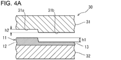
- FIG. 4A to 4C are cross-sectional views showing a first specific example of the HS press device.
- 4A shows a state in the initial stage of machining
- FIG. 4B shows a state in the middle of machining
- FIG. 4C shows a state in the last stage of machining.
- the HS press device 30 includes an upper die 31 and a lower die 32.
- the upper mold 31 includes a first surface 31 a corresponding to the thick portion 12 and a second surface 31 b corresponding to the thin portion 13.
- the height h2 of the step between the first surface 31a and the second surface 31b in the upper mold 31 is smaller than the height h1 of the step between the thick portion 12 and the thin portion 13 in the differential thickness steel plate 11.
- the upper mold 31 is supported by an upper mold holder (not shown). Cooling water circulates inside the upper mold 31.
- the high-temperature differential thickness steel plate 11 including the thick portion 12 and the thin portion 13 is placed on the lower mold 32.
- the first surface 31 a of the upper die 31 comes into contact with the thick portion 12 of the differential thickness steel plate 11.
- the thick portion 12 is processed by the first surface 31a.
- the second surface 31b of the upper die 31 comes into contact with the thin portion 13 of the differential thickness steel plate 11 as shown in FIG. 4C.
- the thin portion 13 is processed by the second surface 31b.
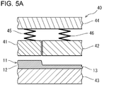
- FIG. 5A to 5C are cross-sectional views showing a second specific example of the HS press device.
- FIG. 5A shows a state in the initial stage of processing
- FIG. 5B shows a state in the middle of processing
- FIG. 5C shows a state in the end of processing.
- the HS press device 40 includes a first upper die 41, a second upper die 42, and a lower die 43.
- the first upper mold 41 is disposed at a position corresponding to the thick portion 12.
- the second upper mold 42 is disposed at a position corresponding to the thin portion 13.
- the first upper mold 41 is supported by the upper mold holder 44 via the first pressure member 45.
- the second upper mold 42 is supported by the upper mold holder 44 via the second pressure member 46.
- the first and second pressure members 45 and 46 are hydraulic cylinders or springs. Cooling water circulates inside the first and second upper molds 41 and 42.
- the high-temperature differential thickness steel plate 11 including the thick portion 12 and the thin portion 13 is placed on the lower mold 43.
- the first upper mold 41 comes into contact with the thick portion 12 of the differential thickness steel plate 11.
- the first pressure member 45 contracts while applying pressure to the first upper mold 41, and the thick portion 12 is processed by the first upper mold 41.
- the second upper mold 42 comes into contact with the thin portion 13 of the differential thickness steel plate 11 as shown in FIG. 5C.
- the second pressure member 46 contracts while applying pressure to the second upper mold 42, and the thin portion 13 is processed by the second upper mold 42.
- the processing of the thick portion 12 precedes the processing of the thin portion 13 during HS. Therefore, the cooling of the thick portion 12 precedes the cooling of the thin portion 13. As a result, it is possible to enhance the cooling of the thick portion 12.
- the heating furnace 20 is used in the first heating process and the second heating process.
- the heating furnace 20 heats the steel plate (blank) before hot forging.
- the heating furnace 20 heats the differential thickness steel plate obtained by hot forging.
- the steel sheet is heated to 950 ° C. or higher.
- the differential thickness steel sheet is heated to a temperature not lower than the A c3 transformation point and not higher than “A c3 transformation point + 150 ° C.”.
- the production line may include one heating furnace 20, and the heating furnace 20 may be shared by the first and second heating processes. However, the target heating temperature in the first heating step may not match the target heating temperature in the second heating step.
- the production line may include two or more heating furnaces 20 and each heating furnace 20 may be dedicated for each heating process.
- the inside of the heating furnace 20 is partitioned by a plurality of stages of shelves, and a steel plate or a differential thickness steel plate is stored in each shelf.
- steel plates blades
- differential thickness steel plates hereinafter collectively referred to as “steel plates”.
- the steel plates are inserted into or removed from the mold of the forging press device 21. Further, the steel sheets are inserted into or removed from the mold of the HS press device 23. Therefore, the steel plates are transported by a manipulator 50 (a transport robot) that can lift the steel plates.
- the conveyance performed by the manipulator 50 is as follows. -Conveyance from the heating furnace 20 to the forging press apparatus 21-When reheating is required Conveyance from the forging press apparatus 21 to the heating furnace 20-Heating furnace from the forging press apparatus 21 after hot forging is completed Conveyance up to 20 / Heating furnace 20 to HS press device 23 Conveyance and take-out of press-molded product from HS press device 23
- the production line may include a single manipulator 50, and the manipulator 50 may be responsible for all conveyance.
- the production line may include a plurality of manipulators 50 and allocate the conveyance to each manipulator 50.
- the movable range of the manipulator 50 is set so that the transport destination and the transport source in each of the devices 21, 23 and 20 enter.
- Control device The temperature of the blank taken out from the heating furnace 20 gradually decreases. For this reason, it is necessary to manage the conveyance time by the manipulator 50 and the heating temperature by the heating furnace 20. Further, the take-out operation and the charging operation by the manipulator 50 need to be interlocked with the heating furnace 20 and the press devices 21 and 23. For these reasons, the devices 21, 23 and 20 constituting the production line are controlled by the control device 51.
- the control device 51 outputs a signal for controlling the opening / closing of the door of the heating furnace 20 and the operation of the manipulator 50.
- a plurality of steel plates (blanks) or differential thickness steel plates are stored in the heating furnace 20.
- the storage status of each steel sheet in the heating furnace 20 is recorded in the memory of the control device 51.
- the control device 51 determines whether or not the steel plates can be taken out from the heating furnace 20 based on the in-furnace temperature of the heating furnace 20 and the in-furnace time of each steel plate.
- the control device 51 has the following functions, for example.
- signals such as processing preparation completion and processing completion are input to the control device 51 from the forging press device 21 and the HS press device 23.
- the operation control of the manipulator 50 may control the position of the manipulator 50 every moment.
- the operation control of the manipulator 50 may be such that the manipulator 50 performs a predetermined operation in response to a signal output from the control device 51.
- the control apparatus 51 may be provided with the function to change the taking-out temperature of the blank from the heating furnace 20 according to air temperature.
- the control device 51 may have a function of changing the conveying time from the heating furnace 20 to the forging press device 21 and the HS press device 23 according to the temperature.
- the following numerical analysis test was conducted in order to confirm the effect of the method for manufacturing a press-formed product of the present embodiment. Specifically, two types of analysis models having a hat-shaped cross section assuming a bumper beam were produced. And about each model, the numerical analysis which simulated the three-point bending crushing test was implemented. In general, the three-point bending crush test is used for evaluating the performance of a bumper beam.
- FIG. 6A and 6B are cross-sectional views schematically showing an analysis model used in the bending test of the example.
- FIG. 6A shows an analysis model of a comparative example
- FIG. 6B shows an analysis model of an example of the present invention.
- the model A of the comparative example has a constant thickness of 2.0 mm over the entire area.
- the plate thickness of the top plate portion 2 was set to 1.0 mm, which is half the plate thickness of other portions.
- the tensile strength of both models A and B was 1300 MPa.
- a common closing plate (not shown) was joined to the flange portion 4, and the gap between the flange portions 4 was closed by the closing plate.
- Each model A and B was supported at two points from the closing plate side.
- the support point interval of each model A and B was 800 mm.
- the impactor was made to collide with the center of the support point of each model A and B from the top plate part 2 side, and each model A and B was crushed.
- the radius of curvature of the tip of the impactor was 150 mm.
- the impact speed of the impactor was 9 km / h.
- FIG. 7 is a table summarizing the test results of the examples. The results shown in FIG. 7 indicate the following.
- the load distribution according to the impactor stroke is almost the same between the model A of the comparative example and the model B of the present invention. That is, the maximum load and the absorbed energy when a collision load is applied are approximately the same in the model A of the comparative example and the model B of the present invention example. Nevertheless, the weight of model B of the present invention is lighter. From this, it was found that the thickness of the top plate portion 2 has little influence on the component performance, and by reducing the thickness of the top plate portion 2, the weight can be reduced while securing the component performance.
- the method for manufacturing a press-formed product of the present invention can be effectively used for manufacturing a press-formed product for automobiles that require high strength.
Landscapes
- Engineering & Computer Science (AREA)
- Mechanical Engineering (AREA)
- Chemical & Material Sciences (AREA)
- Materials Engineering (AREA)
- Metallurgy (AREA)
- Organic Chemistry (AREA)
- Physics & Mathematics (AREA)
- Thermal Sciences (AREA)
- Crystallography & Structural Chemistry (AREA)
- Shaping Metal By Deep-Drawing, Or The Like (AREA)
- Forging (AREA)
- Heat Treatment Of Articles (AREA)
Abstract
Description
図1は、本発明の実施形態によるプレス成形品の製造方法を示すフロー図である。図2は、本発明の実施形態によるプレス成形品の製造方法の過程を示す模式図である。図1に示すように、本実施形態の製造方法は、準備工程(ステップ#5)と、第1の加熱工程(ステップ#10)と、熱間鍛造工程(ステップ#15)と、第2の加熱工程(ステップ#20)と、ホットスタンピング工程(ステップ#25)と、を含む。第1の加熱工程は鋼板加熱工程である。第2の加熱工程は差厚鋼板加熱工程である。以下、図1及び図2を参照しながら、各工程について詳述する。
焼入れ後の強度は、主にマルテンサイト相の硬さを支配する炭素(C)の含有量によって決まる。そのため、要求される強度に応じてC含有量は決定される。1300MPa以上の引張強さを確保するためには、C含有量は0.15%以上である。より好ましくは、C含有量は0.20%を超える。一方、C含有量が高すぎれば、焼入れ後の靭性が劣化し、脆性破壊が起こる危険性が高まる。したがって、C含有量の上限は0.60%である。C含有量の好ましい上限は0.50%である。
シリコン(Si)は、オーステナイト相から低温変態相へ変態するまでの冷却過程において、炭化物の生成を抑制する。つまり、Siは、延性を劣化させることなく、場合によっては延性を向上させて、焼入れ後の強度を高める。Si含有量が低すぎれば、その効果が得られない。したがって、Si含有量は0.001%以上である。より好ましくは、Si含有量は0.05%以上である。一方、Si含有量が高すぎれば、上記の効果が飽和して経済的に不利となる上、鋼の表面性状の劣化が著しくなる。したがって、Si含有量は2.0%以下である。より好ましくは、Si含有量は1.5%以下である。
マンガン(Mn)は、鋼の焼入れ性を高め、焼入れ後の強度を安定させる。しかし、Mn含有量が低すぎれば、1300MPa以上の引張強さを確保することが難しい。したがって、Mn含有量は0.5%以上である。より好ましくは、Mn含有量は1.0%以上である。Mn含有量が1.0%以上であれば、1350MPa以上の引張強さを確保することが可能となる。一方、Mn含有量が高すぎれば、バンド状のマルテンサイト組織が不均一になり、衝撃特性の劣化が顕著となる。したがって、Mn含有量は3.0%以下である。合金コスト等を考慮すれば、Mn含有量の上限は2.5%である。
リン(P)は、一般には鋼に不可避的に含有される不純物であるが、固溶強化により、強度を高める。一方、P含有量が高すぎれば、溶接性の劣化が著しくなる。また、2500MPa以上の引張強さを狙った場合に脆性破壊の危険性が高まる。したがって、P含有量は0.05%以下である。より好ましくは、P含有量は0.02%以下である。P含有量の下限は特に制限されない。上記の効果をより確実に得るには、P含有量の下限は0.003%である。
硫黄(S)は、鋼に不可避的に含有される不純物であり、MnやTiと結合して硫化物を生成して析出する。この析出物の量が増加しすぎれば、その析出物と主相の界面が破壊の起点となることがある。そのため、S含有量は低いほうが好ましい。したがって、S含有量は0.01%以下である。より好ましくは、S含有量は0.008%以下である。S含有量の下限は特に制限されない。製造コストを考慮すれば、S含有量の下限は0.0015%であり、更に好ましくは0.003%である。
アルミニウム(Al)は、鋼を脱酸して鋼材を健全化し、またTi等の炭窒化物形成元素の歩留まりを向上させる。Al含有量が低すぎれば、上記の効果を得ることが難しい。したがって、Al含有量は0.001%以上である。より好ましくは、Al含有量は0.015%以上である。一方、Al含有量が高すぎれば、溶接性の低下が著しくなり、酸化物系介在物が増加して鋼の表面性状の劣化が著しくなる。したがって、Al含有量は1.0%以下である。より好ましくは、Al含有量は0.080%以下である。本明細書において、Al含有量はsol.Al(酸可溶Al)を意味する。
窒素(N)は、鋼に不可避的に含有される不純物である。溶接性を考慮すれば、N含有量は低いほうが好ましい。一方、N含有量が高すぎれば、溶接性の低下が著しくなる。したがって、N含有量は0.01%以下である。より好ましくは、N含有量は0.006%以下である。N含有量の下限は特に制限されない。製造コストを考慮すれば、N含有量の下限は0.0015%である。
ボロン(B)は、低温靭性を高める。しかし、B含有量が高すぎれば、熱間加工性が劣化して、熱間圧延が困難になる。したがって、B含有量は0.01%以下である。より好ましくは、B含有量は0.0050%以下である。B含有量の下限は特に制限されない。上記の効果をより確実に得るには、B含有量は0.0003%以上である。
Ac3=910-203×√C)-15.2×Ni+44.7×Si+104×V+31.5×Mo-30×Mn-11×Cr-20×Cu+700×P+400×Al+50×Ti …(1)
ここで、式(1)中の各元素記号には、対応する元素の含有量(質量%)が代入される。Alはsol.Alを意味する。
図3は、プレス成形品を製造するための製造ラインの一例を示す模式図である。図3を参照し、上記のプレス成形品を製造するための製造ラインは、鍛造用プレス装置21と、HS用プレス装置23と、少なくとも一つの加熱炉20と、少なくとも一つのマニピュレータ50と、を備える。実際には、製造ラインは、それらの全ての装置21、23、20及び50を制御する制御装置51を備える。
鍛造用プレス装置21は上記の熱間鍛造工程で用いられる。鍛造用プレス装置21は、高温の鋼板(ブランク)を金型21a及び21bによって繰り返し叩き、差厚鋼板に鍛造する。鍛造用プレス装置21は鍛造した差厚鋼板を冷却する水冷装置を備えることが望ましい。靭性に優れた最終製品(プレス成形品)を得るためである。
HS用プレス装置23は上記のHS工程で用いられる。HS用プレス装置23は、高温の差厚鋼板を金型23a及び23bによってプレス加工し、プレス成形品を成形する。更に、HS用プレス装置23は、冷却された金型23a及び23b、又は金型23a及び23bから噴射される冷却水によって金型23a及び23b内のプレス成形品を冷却し、焼き入れする。
図3を参照し、加熱炉20は、上記の第1の加熱工程及び第2の加熱工程で用いられる。加熱炉20は、熱間鍛造前の鋼板(ブランク)を加熱する。また、加熱炉20は、熱間鍛造により得られた差厚鋼板を加熱する。鋼板は950℃以上に加熱される。差厚鋼板はAc3変態点以上、「Ac3変態点+150℃」以下の温度に加熱される。製造ラインは、一つの加熱炉20を備え、その加熱炉20を第1及び第2の加熱工程で共用してもよい。ただし、第1の加熱工程で目標とする加熱温度と、第2の加熱工程で目標とする加熱温度が一致しないこともある。そのため、一つの加熱炉20を共用する場合、加熱炉20の内部を目標加熱温度の異なる二つ以上の区画に分けすることが望ましい。もっとも、製造ラインは、二つ以上の加熱炉20を備え、各加熱炉20を各加熱工程で専用としてもよい。製造ラインをコンパクトにするため、加熱炉20の内部は複数段の棚によって仕切られ、それぞれの棚に鋼板又は差厚鋼板が格納されることが望ましい。
鋼板(ブランク)及び差厚鋼板(以下、これらを総称して「鋼板類」ともいう)は900℃以上に加熱されるため、鋼板類を人間が直接扱うことはできない。従って、鋼板類の搬送は機械によって行われる。鋼板類は、鍛造用プレス装置21の金型間に装入されたり、取出されたりする。更に、鋼板類は、HS用プレス装置23の金型間に装入されたり、取出されたりする。そのため、鋼板類の搬送は、鋼板類を持ち上げることができるマニピュレータ50(搬送ロボット)によって行われる。
・加熱炉20から鍛造用プレス装置21までの搬送
・再加熱が必要な場合の鍛造用プレス装置21から加熱炉20までの搬送
・熱間鍛造が完了した後の鍛造用プレス装置21から加熱炉20までの搬送
・加熱炉20からHS用プレス装置23までの搬送
・HS用プレス装置23からのプレス成形品の取出
加熱炉20から取り出されたブランクの温度は次第に低下していく。このため、マニピュレータ50による搬送時間及び加熱炉20による加熱温度を管理する必要がある。また、マニピュレータ50による取り出し動作と装入動作が加熱炉20及びプレス装置21及び23と連動する必要がある。このような理由により製造ラインを構成する各装置21、23及び20は制御装置51によって制御される。
・加熱炉20からの鋼板の取出可否判定
・加熱炉20から鍛造用プレス装置21までのマニピュレータ50の動作制御
・加熱炉20内の空き領域の管理
・再加熱が必要な場合の鍛造用プレス装置21から加熱炉20までのマニピュレータ50の動作制御
・熱間鍛造が完了後した後の鍛造用プレス装置21から加熱炉20までのマニピュレータ50の動作制御
・加熱炉20からの差厚鋼板の取出可否判定
・加熱炉20からHS用プレス装置23までのマニピュレータ50の動作制御
・HS用プレス装置23からプレス成形品を取り出すマニピュレータ50の動作制御
図6A及び図6Bは、実施例の曲げ試験で用いた解析モデルを模式的に示す断面図である。図6Aは比較例の解析モデルを示し、図6Bは本発明例の解析モデルを示す。図6Aに示すように、比較例のモデルAは、全域にわたって板厚を一定の2.0mmにした。図6Bに示すように、本発明例のモデルBは、天板部2の板厚をその他の部分の板厚の半分の1.0mmにした。
図7は、実施例の試験結果をまとめた図である。図7に示す結果から以下のことが示される。
2 天板部
3 縦壁部
4 フランジ部
5 上側稜線部
6 下側稜線部
10 鋼板
20 第1の加熱炉
21 鍛造用プレス装置
21a、21b 金型
11 差厚鋼板
12 厚肉部分
13 薄肉部分
t1 厚肉部分の板厚
t2 薄肉部分の板厚
22 第2の加熱炉
23、30、40 ホットスタンピング用プレス装置
23a、23b 金型
50 マニピュレータ
51 制御装置
Claims (9)
- 鋼板を950℃以上に加熱する鋼板加熱工程と、
プレス装置を用い、前記鋼板を鍛造し、差厚鋼板を成形する熱間鍛造工程と、
前記プレス装置と異なるプレス装置を用い、前記差厚鋼板を金型によってプレス加工してプレス成形品に成形し、前記プレス成形品を前記金型内で冷却するホットスタンピング工程と、を含む、プレス成形品の製造方法。 - 請求項1に記載のプレス成形品の製造方法であって、
前記熱間鍛造工程の後、前記ホットスタンピング工程の前に、前記差厚鋼板をAc3変態点以上、「Ac3変態点+150℃」以下の温度に加熱する差厚鋼板加熱工程を含む、プレス成形品の製造方法。 - 請求項2に記載のプレス成形品の製造方法であって、
前記熱間鍛造工程の後、前記差厚鋼板加熱工程の前に、前記差厚鋼板を冷却する冷却工程を含む、プレス成形品の製造方法。 - 請求項1から3のいずれか1項に記載のプレス成形品の製造方法であって、
前記差厚鋼板は厚みの厚い部分と厚みの薄い部分とを有し、前記厚みの厚い部分の板厚t1と前記厚みの薄い部分の板厚t2との比「t1/t2」が1.8を超える、プレス成形品の製造方法。 - 請求項1から4のいずれか1項に記載のプレス成形品の製造方法であって、
前記プレス成形品の引張強さが1300MPa以上である、プレス成形品の製造方法。 - 請求項1から5のいずれか1項に記載のプレス成形品の製造方法であって、
前記鋼板は、質量%で、C:0.15~0.60%、Si:0.001~2.0%、Mn:0.5~3.0%、P:0.05%以下、S:0.01%以下、sol.Al:0.001~1.0%、N:0.01%以下及びB:0.01%以下を含有し、残部がFe及び不純物からなる、プレス成形品の製造方法。 - 請求項6に記載のプレス成形品の製造方法であって、
前記鋼板は、Feの一部に代えて、Ti、Nb、V、Cr、Mo、Cu及びNiからなる群から選択される1種又は2種以上を合計で0.03~1.0%含有する、プレス成形品の製造方法。 - 鍛造用プレス装置と、
ホットスタンピング用プレス装置と、
少なくとも一つの加熱炉と、
少なくとも一つのマニピュレータと、を備える、プレス成形品の製造ライン。 - 請求項8に記載のプレス成形品の製造ラインであって、
前記鍛造用プレス装置、前記ホットスタンピング用プレス装置、前記加熱炉、及び前記マニピュレータを制御する制御装置を備える、プレス成形品の製造ライン。
Priority Applications (10)
| Application Number | Priority Date | Filing Date | Title |
|---|---|---|---|
| EP17799430.8A EP3459649B1 (en) | 2016-05-18 | 2017-05-17 | Method of producing press-formed product, and press-formed product production line |
| KR1020187036279A KR101992077B1 (ko) | 2016-05-18 | 2017-05-17 | 프레스 성형품의 제조 방법 |
| MX2018014105A MX370243B (es) | 2016-05-18 | 2017-05-17 | Metodo de produccion de producto formado en prensa y linea de produccion de productos formados en prensa. |
| JP2017551348A JP6388084B2 (ja) | 2016-05-18 | 2017-05-17 | プレス成形品の製造方法及び製造ライン |
| BR112018073277-0A BR112018073277A2 (pt) | 2016-05-18 | 2017-05-17 | método de produção de produto moldado em prensa e linha de produção de produto moldado em prensa |
| US16/097,881 US10744547B2 (en) | 2016-05-18 | 2017-05-17 | Method of producing press-formed product |
| CN201780030625.4A CN109153060B (zh) | 2016-05-18 | 2017-05-17 | 压制成型品的制造方法和生产线 |
| RU2018144109A RU2708283C1 (ru) | 2016-05-18 | 2017-05-17 | Способ производства прессованного продукта и линия для производства прессованного продукта |
| KR1020197013577A KR20190053305A (ko) | 2016-05-18 | 2017-05-17 | 프레스 성형품의 제조 라인 |
| CA3024539A CA3024539C (en) | 2016-05-18 | 2017-05-17 | Method of producing press-formed product, and press-formed product production line |
Applications Claiming Priority (2)
| Application Number | Priority Date | Filing Date | Title |
|---|---|---|---|
| JP2016099862 | 2016-05-18 | ||
| JP2016-099862 | 2016-05-18 |
Publications (1)
| Publication Number | Publication Date |
|---|---|
| WO2017200006A1 true WO2017200006A1 (ja) | 2017-11-23 |
Family
ID=60325220
Family Applications (1)
| Application Number | Title | Priority Date | Filing Date |
|---|---|---|---|
| PCT/JP2017/018535 WO2017200006A1 (ja) | 2016-05-18 | 2017-05-17 | プレス成形品の製造方法及び製造ライン |
Country Status (10)
| Country | Link |
|---|---|
| US (1) | US10744547B2 (ja) |
| EP (1) | EP3459649B1 (ja) |
| JP (1) | JP6388084B2 (ja) |
| KR (2) | KR101992077B1 (ja) |
| CN (1) | CN109153060B (ja) |
| BR (1) | BR112018073277A2 (ja) |
| CA (1) | CA3024539C (ja) |
| MX (1) | MX370243B (ja) |
| RU (1) | RU2708283C1 (ja) |
| WO (1) | WO2017200006A1 (ja) |
Cited By (3)
| Publication number | Priority date | Publication date | Assignee | Title |
|---|---|---|---|---|
| CN111318600A (zh) * | 2018-12-13 | 2020-06-23 | 丰田自动车株式会社 | 钢板构件及其制造方法 |
| CN113909362A (zh) * | 2021-10-29 | 2022-01-11 | 台州环联科技有限公司 | 一种红冲机床 |
| WO2022045069A1 (ja) * | 2020-08-28 | 2022-03-03 | 日本製鉄株式会社 | プレス成形品の製造方法、並びに、プレス成形品の製造に用いられるトレイ及び熱間プレス製造ライン |
Families Citing this family (13)
| Publication number | Priority date | Publication date | Assignee | Title |
|---|---|---|---|---|
| JP6548620B2 (ja) * | 2016-09-06 | 2019-07-24 | 日本製鉄株式会社 | 熱間プレス装置 |
| JP6575015B2 (ja) * | 2017-07-07 | 2019-09-18 | 本田技研工業株式会社 | 車体構造 |
| CN110039313B (zh) * | 2019-05-24 | 2024-03-29 | 东营哈东工业技术研究院有限责任公司 | 一种节能型热成形钢类零件分步成形装备及工艺 |
| CN110935803B (zh) * | 2019-11-29 | 2022-01-04 | 中国华西企业有限公司 | 一种厚钢板的变形处理方法 |
| JP7448396B2 (ja) | 2020-03-27 | 2024-03-12 | 住友重機械工業株式会社 | 成形システム |
| CN111571235B (zh) * | 2020-05-12 | 2022-06-14 | 艾伯纳工业炉(太仓)有限公司 | 一种金属板材的热成型生产线 |
| CN112045125A (zh) * | 2020-09-30 | 2020-12-08 | 江苏永茂普隆汽车配件制造有限公司 | 一种锻件的精确锻造工艺 |
| CN112474959A (zh) * | 2020-11-02 | 2021-03-12 | 上海凌云工业科技有限公司凌云汽车技术分公司 | 一种不等厚截面工件热压成型模具及其热压成型工艺 |
| CN113000752B (zh) * | 2021-04-08 | 2022-11-08 | 重庆大学 | 一种锻件高压水除鳞装置及方法 |
| CN114434099B (zh) * | 2021-12-30 | 2023-07-07 | 富联裕展科技(深圳)有限公司 | 终端边框制造方法、终端边框、终端及生产线 |
| CN114798945A (zh) * | 2022-04-29 | 2022-07-29 | 永康中奥自动化科技有限公司 | 一种带机械手的液压拉伸设备 |
| CN114713712B (zh) * | 2022-05-10 | 2024-05-07 | 合肥海德数控液压设备有限公司 | 一种带拔伸冲孔功能的热冲压自动化生产线 |
| CN116493536B (zh) * | 2023-06-30 | 2023-09-15 | 苏州铂源航天航空新材料有限公司 | 一种航空钛合金件锻造装置 |
Citations (5)
| Publication number | Priority date | Publication date | Assignee | Title |
|---|---|---|---|---|
| JPH11104750A (ja) * | 1997-09-30 | 1999-04-20 | Nissan Motor Co Ltd | 突き合わせ溶接板のプレス成形方法 |
| JP2004353026A (ja) * | 2003-05-28 | 2004-12-16 | Sumitomo Metal Ind Ltd | 熱間成形法と熱間成形部材 |
| JP2014226712A (ja) * | 2013-05-24 | 2014-12-08 | 新日鐵住金株式会社 | 差厚鋼板製品の製造ライン及び製造方法 |
| WO2015092929A1 (ja) * | 2013-12-20 | 2015-06-25 | 新日鐵住金株式会社 | 熱間プレス鋼板部材、その製造方法及び熱間プレス用鋼板 |
| JP2016059926A (ja) * | 2014-09-16 | 2016-04-25 | ダイハツ工業株式会社 | 熱間プレス加工用板金材の搬送装置 |
Family Cites Families (24)
| Publication number | Priority date | Publication date | Assignee | Title |
|---|---|---|---|---|
| US2586881A (en) * | 1950-01-03 | 1952-02-26 | M B Mfg Company Inc | Driving unit for electromagnetic vibration exciters |
| SE435527B (sv) * | 1973-11-06 | 1984-10-01 | Plannja Ab | Forfarande for framstellning av en detalj av herdat stal |
| SU1558706A1 (ru) | 1987-12-08 | 1990-04-23 | Воронежское производственное объединение по выпуску тяжелых механических прессов "Воронежтяжмехпресс" | Автоматизированна лини дл штамповки лонжеронов |
| US5928604A (en) * | 1996-11-27 | 1999-07-27 | Caterpillar Inc. | Automated system for carburizing a component |
| DE10049660B4 (de) * | 2000-10-07 | 2005-02-24 | Daimlerchrysler Ag | Verfahren zum Herstellen lokal verstärkter Blechumformteile |
| CN1166469C (zh) * | 2000-11-27 | 2004-09-15 | 中国第二重型机械集团公司 | 带整体支承裙座的厚壁封头的制造方法 |
| JP4801277B2 (ja) | 2001-04-20 | 2011-10-26 | 本田技研工業株式会社 | 車体パネルの成形方法 |
| JP4415684B2 (ja) | 2004-01-23 | 2010-02-17 | トヨタ自動車株式会社 | サイドメンバのキックアップ部構造 |
| JP4677821B2 (ja) * | 2005-04-22 | 2011-04-27 | 日産自動車株式会社 | 差厚板の製造方法および製造装置 |
| JP4321548B2 (ja) * | 2005-07-14 | 2009-08-26 | Jfeスチール株式会社 | 熱間鍛造設備 |
| KR20050080133A (ko) | 2005-07-15 | 2005-08-11 | 대한금속(주) | 볼 하우징의 제조방법 |
| DE102005051403B3 (de) * | 2005-10-25 | 2007-03-15 | Benteler Automobiltechnik Gmbh | Verfahren zur Herstellung eines Blechformteiles |
| CN100453203C (zh) * | 2006-09-12 | 2009-01-21 | 钟六妹 | 一种优质碳素钢钩、环类零件的锻造方法 |
| CN101293255A (zh) | 2008-06-17 | 2008-10-29 | 钢铁研究总院 | 经济型热成型马氏体钢板生产方法 |
| DE102009003508B4 (de) * | 2009-02-19 | 2013-01-24 | Thyssenkrupp Steel Europe Ag | Verfahren zur Herstellung eines pressgehärteten Metallbauteils |
| CN101486060B (zh) * | 2009-02-24 | 2010-12-29 | 山东大学 | 高强度钢零件的热成形和冲孔一体化工艺及模具 |
| DE102009025821B4 (de) * | 2009-05-18 | 2011-03-31 | Thyssenkrupp Steel Europe Ag | Verfahren zur Herstellung eines Metallbauteils |
| KR100993988B1 (ko) | 2010-01-29 | 2010-11-11 | 현대하이스코 주식회사 | 간접 핫 스탬핑 성형방법 |
| CN106435359B (zh) * | 2011-03-09 | 2018-07-31 | 新日铁住金株式会社 | 热压用钢板及其制造方法和高强度部件的制造方法 |
| US9238847B2 (en) * | 2011-08-05 | 2016-01-19 | Honda Motor Co., Ltd. | Tailored hardening of boron steel |
| DE102011117265A1 (de) * | 2011-10-28 | 2013-05-02 | GEDIA Gebrüder Dingerkus GmbH | Verfahren zur Herstellung eines Formteiles aus hochfestem oder höchstfestem Stahl |
| JP2015188927A (ja) | 2014-03-28 | 2015-11-02 | 大同特殊鋼株式会社 | 鍛造部材の製造方法 |
| KR20160002251A (ko) | 2014-06-30 | 2016-01-07 | 주식회사 신영 | 핫스탬핑용 냉각 장치 |
| ES2827455T3 (es) * | 2016-02-25 | 2021-05-21 | Benteler Automobiltechnik Gmbh | Método de fabricación de un componente de automóvil con al menos dos zonas de resistencia mutuamente diferentes |
-
2017
- 2017-05-17 WO PCT/JP2017/018535 patent/WO2017200006A1/ja unknown
- 2017-05-17 KR KR1020187036279A patent/KR101992077B1/ko active IP Right Grant
- 2017-05-17 JP JP2017551348A patent/JP6388084B2/ja active Active
- 2017-05-17 KR KR1020197013577A patent/KR20190053305A/ko not_active Application Discontinuation
- 2017-05-17 CA CA3024539A patent/CA3024539C/en not_active Expired - Fee Related
- 2017-05-17 RU RU2018144109A patent/RU2708283C1/ru active
- 2017-05-17 US US16/097,881 patent/US10744547B2/en active Active
- 2017-05-17 EP EP17799430.8A patent/EP3459649B1/en active Active
- 2017-05-17 MX MX2018014105A patent/MX370243B/es active IP Right Grant
- 2017-05-17 BR BR112018073277-0A patent/BR112018073277A2/pt not_active Application Discontinuation
- 2017-05-17 CN CN201780030625.4A patent/CN109153060B/zh active Active
Patent Citations (5)
| Publication number | Priority date | Publication date | Assignee | Title |
|---|---|---|---|---|
| JPH11104750A (ja) * | 1997-09-30 | 1999-04-20 | Nissan Motor Co Ltd | 突き合わせ溶接板のプレス成形方法 |
| JP2004353026A (ja) * | 2003-05-28 | 2004-12-16 | Sumitomo Metal Ind Ltd | 熱間成形法と熱間成形部材 |
| JP2014226712A (ja) * | 2013-05-24 | 2014-12-08 | 新日鐵住金株式会社 | 差厚鋼板製品の製造ライン及び製造方法 |
| WO2015092929A1 (ja) * | 2013-12-20 | 2015-06-25 | 新日鐵住金株式会社 | 熱間プレス鋼板部材、その製造方法及び熱間プレス用鋼板 |
| JP2016059926A (ja) * | 2014-09-16 | 2016-04-25 | ダイハツ工業株式会社 | 熱間プレス加工用板金材の搬送装置 |
Non-Patent Citations (1)
| Title |
|---|
| See also references of EP3459649A4 * |
Cited By (3)
| Publication number | Priority date | Publication date | Assignee | Title |
|---|---|---|---|---|
| CN111318600A (zh) * | 2018-12-13 | 2020-06-23 | 丰田自动车株式会社 | 钢板构件及其制造方法 |
| WO2022045069A1 (ja) * | 2020-08-28 | 2022-03-03 | 日本製鉄株式会社 | プレス成形品の製造方法、並びに、プレス成形品の製造に用いられるトレイ及び熱間プレス製造ライン |
| CN113909362A (zh) * | 2021-10-29 | 2022-01-11 | 台州环联科技有限公司 | 一种红冲机床 |
Also Published As
| Publication number | Publication date |
|---|---|
| KR20190053305A (ko) | 2019-05-17 |
| KR101992077B1 (ko) | 2019-06-21 |
| RU2708283C1 (ru) | 2019-12-05 |
| EP3459649A4 (en) | 2019-04-03 |
| EP3459649B1 (en) | 2021-06-23 |
| CA3024539C (en) | 2019-03-26 |
| JP6388084B2 (ja) | 2018-09-12 |
| KR20180137032A (ko) | 2018-12-26 |
| EP3459649A1 (en) | 2019-03-27 |
| JPWO2017200006A1 (ja) | 2018-05-31 |
| CN109153060B (zh) | 2021-06-25 |
| BR112018073277A2 (pt) | 2019-02-19 |
| CN109153060A (zh) | 2019-01-04 |
| MX2018014105A (es) | 2019-04-29 |
| US20190091748A1 (en) | 2019-03-28 |
| US10744547B2 (en) | 2020-08-18 |
| MX370243B (es) | 2019-12-04 |
| CA3024539A1 (en) | 2017-11-23 |
Similar Documents
| Publication | Publication Date | Title |
|---|---|---|
| JP6388084B2 (ja) | プレス成形品の製造方法及び製造ライン | |
| Taylor et al. | Critical review of automotive hot-stamped sheet steel from an industrial perspective | |
| CN104936716B (zh) | 热压成形钢构件的制造方法 | |
| CN106119694B (zh) | 用中薄板坯直接轧制的抗拉强度≥1900MPa热成形钢及生产方法 | |
| US8733144B2 (en) | Method and apparatus for hot forming and hardening a blank | |
| CN106086684B (zh) | 用薄板坯直接轧制的抗拉强度≥1900MPa薄热成形钢及生产方法 | |
| US9358602B2 (en) | Method for producing press-formed product | |
| CN101805821A (zh) | 钢材冲压成形一体化处理方法 | |
| CN106119693B (zh) | 用薄板坯直接轧制的抗拉强度≥2100MPa薄热成形钢及生产方法 | |
| Billur | Hot formed steels | |
| JP2010236560A (ja) | 衝撃吸収特性に優れた構造部材の製造方法 | |
| US11219937B2 (en) | Centering and selective heating | |
| JP6288378B2 (ja) | パネル状成形品、車両用ドア、及び、パネル状成形品の製造方法 | |
| CN105829562A (zh) | 热压钢板构件、其制造方法以及热压用钢板 | |
| CN103334057A (zh) | 一种热轧马氏体钢及其生产方法 | |
| CN106086686B (zh) | 用中薄板坯直接轧制的抗拉强度≥2100MPa热成形钢及生产方法 | |
| US20190032164A1 (en) | Heat treatment method and heat treatment device | |
| CN104988386A (zh) | 高扩孔率汽车大梁用钢420l的生产方法 | |
| CN112962021B (zh) | 激光拼焊后用于整体热冲压成形的强塑钢板及生产方法 | |
| US11230746B2 (en) | Heat treatment method and heat treatment apparatus | |
| CN107502827A (zh) | 汽车横梁用热轧钢及其加工方法 | |
| CN106222556B (zh) | 用中薄板坯直接轧制的抗拉强度≥1300MPa热成形钢及生产方法 | |
| CN101906576B (zh) | 一种热连轧钢板的生产方法 | |
| JP5251764B2 (ja) | 車両用構造部材とその製造方法 | |
| JP5717024B2 (ja) | 薄肉鋼加工品及びその熱処理方法 |
Legal Events
| Date | Code | Title | Description |
|---|---|---|---|
| ENP | Entry into the national phase |
Ref document number: 2017551348 Country of ref document: JP Kind code of ref document: A |
|
| ENP | Entry into the national phase |
Ref document number: 3024539 Country of ref document: CA |
|
| NENP | Non-entry into the national phase |
Ref country code: DE |
|
| REG | Reference to national code |
Ref country code: BR Ref legal event code: B01A Ref document number: 112018073277 Country of ref document: BR |
|
| 121 | Ep: the epo has been informed by wipo that ep was designated in this application |
Ref document number: 17799430 Country of ref document: EP Kind code of ref document: A1 |
|
| ENP | Entry into the national phase |
Ref document number: 20187036279 Country of ref document: KR Kind code of ref document: A |
|
| ENP | Entry into the national phase |
Ref document number: 2017799430 Country of ref document: EP Effective date: 20181218 |
|
| ENP | Entry into the national phase |
Ref document number: 112018073277 Country of ref document: BR Kind code of ref document: A2 Effective date: 20181112 |