WO2017199601A1 - 錠剤印刷装置および洗浄方法 - Google Patents
錠剤印刷装置および洗浄方法 Download PDFInfo
- Publication number
- WO2017199601A1 WO2017199601A1 PCT/JP2017/013880 JP2017013880W WO2017199601A1 WO 2017199601 A1 WO2017199601 A1 WO 2017199601A1 JP 2017013880 W JP2017013880 W JP 2017013880W WO 2017199601 A1 WO2017199601 A1 WO 2017199601A1
- Authority
- WO
- WIPO (PCT)
- Prior art keywords
- cleaning
- blade
- printing apparatus
- cap
- tablet
- Prior art date
- Legal status (The legal status is an assumption and is not a legal conclusion. Google has not performed a legal analysis and makes no representation as to the accuracy of the status listed.)
- Ceased
Links
Images






Classifications
-
- A—HUMAN NECESSITIES
- A61—MEDICAL OR VETERINARY SCIENCE; HYGIENE
- A61J—CONTAINERS SPECIALLY ADAPTED FOR MEDICAL OR PHARMACEUTICAL PURPOSES; DEVICES OR METHODS SPECIALLY ADAPTED FOR BRINGING PHARMACEUTICAL PRODUCTS INTO PARTICULAR PHYSICAL OR ADMINISTERING FORMS; DEVICES FOR ADMINISTERING FOOD OR MEDICINES ORALLY; BABY COMFORTERS; DEVICES FOR RECEIVING SPITTLE
- A61J3/00—Devices or methods specially adapted for bringing pharmaceutical products into particular physical or administering forms
-
- B—PERFORMING OPERATIONS; TRANSPORTING
- B41—PRINTING; LINING MACHINES; TYPEWRITERS; STAMPS
- B41J—TYPEWRITERS; SELECTIVE PRINTING MECHANISMS, i.e. MECHANISMS PRINTING OTHERWISE THAN FROM A FORME; CORRECTION OF TYPOGRAPHICAL ERRORS
- B41J2/00—Typewriters or selective printing mechanisms characterised by the printing or marking process for which they are designed
- B41J2/005—Typewriters or selective printing mechanisms characterised by the printing or marking process for which they are designed characterised by bringing liquid or particles selectively into contact with a printing material
- B41J2/01—Ink jet
- B41J2/135—Nozzles
- B41J2/165—Prevention or detection of nozzle clogging, e.g. cleaning, capping or moistening for nozzles
- B41J2/16517—Cleaning of print head nozzles
- B41J2/16535—Cleaning of print head nozzles using wiping constructions
- B41J2/16538—Cleaning of print head nozzles using wiping constructions with brushes or wiper blades perpendicular to the nozzle plate
-
- A—HUMAN NECESSITIES
- A61—MEDICAL OR VETERINARY SCIENCE; HYGIENE
- A61J—CONTAINERS SPECIALLY ADAPTED FOR MEDICAL OR PHARMACEUTICAL PURPOSES; DEVICES OR METHODS SPECIALLY ADAPTED FOR BRINGING PHARMACEUTICAL PRODUCTS INTO PARTICULAR PHYSICAL OR ADMINISTERING FORMS; DEVICES FOR ADMINISTERING FOOD OR MEDICINES ORALLY; BABY COMFORTERS; DEVICES FOR RECEIVING SPITTLE
- A61J3/00—Devices or methods specially adapted for bringing pharmaceutical products into particular physical or administering forms
- A61J3/06—Devices or methods specially adapted for bringing pharmaceutical products into particular physical or administering forms into the form of pills, lozenges or dragees
-
- B—PERFORMING OPERATIONS; TRANSPORTING
- B41—PRINTING; LINING MACHINES; TYPEWRITERS; STAMPS
- B41J—TYPEWRITERS; SELECTIVE PRINTING MECHANISMS, i.e. MECHANISMS PRINTING OTHERWISE THAN FROM A FORME; CORRECTION OF TYPOGRAPHICAL ERRORS
- B41J2/00—Typewriters or selective printing mechanisms characterised by the printing or marking process for which they are designed
- B41J2/005—Typewriters or selective printing mechanisms characterised by the printing or marking process for which they are designed characterised by bringing liquid or particles selectively into contact with a printing material
- B41J2/01—Ink jet
-
- B—PERFORMING OPERATIONS; TRANSPORTING
- B41—PRINTING; LINING MACHINES; TYPEWRITERS; STAMPS
- B41J—TYPEWRITERS; SELECTIVE PRINTING MECHANISMS, i.e. MECHANISMS PRINTING OTHERWISE THAN FROM A FORME; CORRECTION OF TYPOGRAPHICAL ERRORS
- B41J2/00—Typewriters or selective printing mechanisms characterised by the printing or marking process for which they are designed
- B41J2/005—Typewriters or selective printing mechanisms characterised by the printing or marking process for which they are designed characterised by bringing liquid or particles selectively into contact with a printing material
- B41J2/01—Ink jet
- B41J2/135—Nozzles
- B41J2/165—Prevention or detection of nozzle clogging, e.g. cleaning, capping or moistening for nozzles
Definitions
- the present invention relates to a tablet printing apparatus for printing on the surface of a tablet, and a cleaning method for cleaning a discharge surface of a head in which a plurality of ink nozzles are arranged.
- Characters and codes for identifying products are printed on the surface of tablets, which is a form of pharmaceuticals. Such characters and codes may be printed by engraving, but the engraving has a problem of low visibility.
- the types of tablets have been diversified due to the spread of generic drugs. For this reason, in order to make it easy to identify a tablet, a technique for performing clear printing on the surface of the tablet by an ink jet method has attracted attention.
- Patent Documents 1 and 2 describe examples of conventional apparatuses that perform printing on a paper surface by an inkjet method.
- An inkjet tablet printing apparatus ejects ink droplets (hereinafter simply referred to as “ink droplets”) from a plurality of nozzles provided on the ejection surface of a head toward a tablet while transporting the tablets.
- ink droplets ink droplets
- fine powder of the tablet is scattered around the transport path.
- the fine powder of the tablet adheres to the ejection surface of the head, it becomes difficult to eject ink droplets from the nozzle with high accuracy. That is, in a printing apparatus for tablets, there is a specific problem that the ejection accuracy of ink droplets tends to be lowered due to fine powder of tablets.
- This invention is made in view of such a situation, and it aims at providing the tablet printing apparatus and washing
- a first invention of the present application is a tablet printing apparatus that performs printing on the surface of a tablet, the head having a discharge surface on which a plurality of ink nozzles for discharging ink droplets are arranged, and the head A cleaning unit for cleaning the discharge surface, wherein the cleaning unit includes a cap that covers the discharge surface, a cleaning nozzle that discharges cleaning liquid onto the discharge surface, and a blade that wipes the cleaning liquid attached to the discharge surface.
- the cleaning nozzle and the blade are provided inside the cap.
- a second invention of the present application is the tablet printing apparatus according to the first invention, wherein the cleaning unit is configured such that the blade is placed between a storage position in which the blade is stored in the cap and an upright position protruding from the cap.
- a blade moving mechanism for moving is further provided.
- a third invention of the present application is the tablet printing apparatus according to the second invention, wherein the blade has a tip portion that comes into contact with the discharge surface, and a pair of side end portions of the tip portion is an inner edge of the cap. Located outside.
- the fourth invention of the present application is the tablet printing apparatus of the third invention, wherein the cap has a blade housing hole for housing the pair of side end portions of the tip portion.
- the fifth invention of the present application is the tablet printing apparatus according to any one of the second to fourth inventions, wherein the blade is stored in an inclined position with respect to a horizontal plane at the storage position.
- the sixth invention of the present application is the tablet printing apparatus according to any one of the first to fifth inventions, wherein the cleaning nozzle is a tubular nozzle extending along the long side of the ejection surface.
- a seventh invention of the present application is the tablet printing apparatus according to any one of the first to sixth inventions, wherein the cleaning nozzle has a plurality of first discharge ports for discharging the cleaning liquid toward the discharge surface.
- the plurality of first discharge ports are oriented obliquely with respect to the discharge surface.
- the eighth invention of the present application is the tablet printing apparatus according to any one of the first to seventh inventions, wherein the cleaning nozzle has a second discharge port for discharging a cleaning liquid toward the blade.
- a ninth invention of the present application is the tablet printing apparatus according to any one of the first to eighth inventions, wherein the cleaning unit further includes a support member that supports the blade, and is connected to the support member. A passage is provided, and the cleaning liquid discharged from the cleaning nozzle is supplied to the blade through the communication passage.
- the tenth invention of the present application is the tablet printing apparatus according to the ninth invention, wherein the support member has a pair of tapered surfaces whose intervals gradually increase from the communication path toward the blade.
- An eleventh invention of the present application is the tablet printing apparatus according to any one of the first to tenth inventions, wherein a washing area in which the washing unit is arranged, a printing area in which printing is performed on the tablet, and A head moving mechanism for moving the head between the cleaning area and the printing area.
- the twelfth invention of the present application is the tablet printing apparatus of the eleventh invention, further comprising a partition partitioning the cleaning area and the printing area.
- a thirteenth aspect of the present invention is the tablet printing apparatus according to any one of the first to twelfth aspects of the present invention, further comprising a control unit that controls the operation of the head and the cleaning unit, A cleaning liquid supply process for discharging the cleaning liquid from the cleaning nozzle to the discharge surface and a wiping process for wiping the cleaning liquid adhering to the discharge surface with the blade after the cleaning liquid supply process are sequentially executed.
- 14th invention of this application is the tablet printing apparatus of 13th invention, Comprising: The said control part discharges the said washing
- the fifteenth aspect of the present invention is the tablet printing apparatus according to the thirteenth aspect or the fourteenth aspect, wherein the control unit further executes a purge process for ejecting ink from the plurality of ink nozzles of the head.
- a sixteenth invention of the present application is a tablet printing apparatus that performs printing on the surface of a tablet, the head having an ejection surface on which a plurality of ink nozzles that eject ink droplets are arranged, and the ejection surface of the head is washed
- a cleaning unit, and the cleaning unit includes a cap that covers the discharge surface, a blade that wipes the cleaning liquid adhering to the discharge surface, a storage position in which the blade is stored in the cap, and a cap
- a blade moving mechanism that moves between the protruding standing position and the blade, the blade having a tip portion that contacts the discharge surface, and a pair of side end portions of the tip portion is an inner edge of the cap
- the cap has a blade housing hole for housing the pair of side end portions of the tip portion.
- a seventeenth invention of the present application is a cleaning method for cleaning a discharge surface of a head in which a plurality of ink nozzles are arranged in an apparatus for printing on the surface of a tablet, and a) a step of covering the discharge surface with a cap; b) a step of discharging cleaning liquid from the cleaning nozzle provided inside the cap onto the discharge surface; c) a step of separating the discharge surface from the cap; and d) a blade provided inside the cap. Wiping off the cleaning liquid adhering to the ejection surface.
- An eighteenth aspect of the present invention is a cleaning method for cleaning a discharge surface of a head in which a plurality of ink nozzles are arranged in an apparatus for printing on the surface of a tablet, and a) a step of covering the discharge surface with a cap; b) a step of discharging a cleaning liquid onto the discharge surface; c) a step of separating the discharge surface from the cap; and d) a step of wiping off the cleaning liquid adhering to the discharge surface at the tip of a blade.
- the blade is movable between a storage position stored in the cap and an upright position protruding from the cap, and the pair of side end portions of the tip end portion are located outside the inner edge of the cap.
- the cap has a blade housing hole for housing the pair of side end portions of the tip portion.
- the cleaning liquid adhering to the discharge surface can be wiped off with the blade.
- the fine powder of the tablet adhering to the discharge surface can be efficiently removed.
- a cleaning nozzle and a blade are provided inside the cap. For this reason, it is also possible to clean the blade with the cleaning liquid discharged from the cleaning nozzle.
- the tip of the blade comes into contact with a region of the discharge surface that is wider than the inner edge of the cap.
- the cleaning liquid adhering to the ejection surface can be wiped off more efficiently.
- the fine powder of the tablet collected near the inner edge of the cap can be wiped off with the tip of the blade. Thereby, the removal efficiency of the fine powder from a discharge surface can be improved more.
- the blade can be accommodated inside the cap without bending the tip. Thereby, the temporal deformation of the blade can be suppressed.
- the blade stored in the cap can be more efficiently cleaned.
- the cleaning liquid can be supplied over a wide range of the discharge surface.
- the seventh invention of the present application it is possible to suppress the cleaning liquid discharged from the first discharge port from entering the ink nozzles of the head.
- the cleaning liquid can be supplied directly to the blade. Therefore, the blade can be more efficiently cleaned.
- the cleaning liquid can be supplied to the surface of the blade more efficiently.
- the cleaning liquid can be more efficiently supplied to the surface of the blade.
- the eleventh aspect of the present invention by separating the washing area and the printing area, it is easy to keep the printing area where the tablets are conveyed in a clean state.
- the fine powder of the tablet adhering to the ejection surface can be washed away more efficiently.
- the tip of the blade comes into contact with an area of the discharge surface that is wider than the inner edge of the cap.
- the cleaning liquid adhering to the ejection surface can be wiped off efficiently.
- the blade can be stored inside the cap without bending the tip of the blade. Thereby, the temporal deformation of the blade can be suppressed.
- a direction in which a plurality of tablets are transported is referred to as a “transport direction”, and a direction perpendicular to the transport direction is referred to as a “width direction”.
- FIG. 1 is a diagram showing a configuration of a tablet printing apparatus 1 according to an embodiment of the present invention.
- the tablet printing apparatus 1 is an apparatus that prints an image such as a product name, a product code, a company name, and a logo mark on the surface of each tablet 9 while conveying a plurality of tablets 9 that are medicines.
- the tablet printing apparatus 1 of this embodiment includes a tablet transport mechanism 10, a printing unit 20, a drying mechanism 30, and a control unit 40.
- the tablet transport mechanism 10 is a mechanism that transports a plurality of tablets 9 while holding them.
- the tablet transport mechanism 10 includes a pair of pulleys 11 and an annular transport belt 12 that is stretched between the pair of pulleys 11.
- the plurality of tablets 9 put into the tablet printing apparatus 1 are aligned at equal intervals and supplied to the outer peripheral surface of the conveyor belt 12 by a carry-in mechanism 51 configured by a vibration feeder, a conveyance drum, and the like.
- One of the pair of pulleys 11 is rotated by power obtained from the conveyance motor 13. Thereby, the conveyance belt 12 rotates in the direction of the arrow in FIG. At this time, the other of the pair of pulleys 11 is driven to rotate as the conveyor belt 12 rotates.
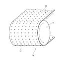
- FIG. 2 is a partial perspective view of the tablet transport mechanism 10.
- the conveyance belt 12 is provided with a plurality of suction holes 14.
- the plurality of suction holes 14 are arranged at equal intervals in the transport direction and the width direction.
- the tablet transport mechanism 10 includes a suction mechanism 15 that sucks out gas from the space inside the transport belt 12.
- the suction mechanism 15 When the suction mechanism 15 is operated, the space inside the conveyor belt 12 becomes a negative pressure lower than the atmospheric pressure.
- the plurality of tablets 9 are sucked and held in the suction holes 14 by the negative pressure.
- the tablet transport mechanism 10 transports the plurality of tablets 9 by rotating the transport belt 12 while holding the plurality of tablets 9 in the plurality of suction holes 14 at a constant interval. Below the four heads 21 described later, the plurality of tablets 9 are conveyed in the horizontal direction.
- the tablet transport mechanism 10 has a blow mechanism 16 inside the transport belt 12.
- the blow mechanism 16 When the blow mechanism 16 is operated, only the suction holes 14 facing the carry-out mechanism 52 among the plurality of suction holes 14 of the transport belt 12 have a positive pressure higher than the atmospheric pressure. Thereby, the suction of the tablet 9 in the suction hole 14 is released, and the tablet 9 is delivered from the transport belt 12 to the carry-out mechanism 52.
- the unloading mechanism 52 unloads the tablet 9 delivered from the conveyance belt 12 to the outside of the tablet printing apparatus 1 by, for example, another conveyance belt.
- the printing unit 20 is a part that records an image on the surface of the tablet 9 conveyed by the conveying belt 12 by an inkjet method.
- the printing unit 20 of the present embodiment has four heads 21.
- the four heads 21 are located above the transport belt 12 and are arranged in a line along the transport direction of the tablets 9.
- the four heads 21 eject ink droplets of different colors (for example, cyan, magenta, yellow, and black) toward the surface of the tablet 9. Then, a multicolor image is recorded on the surface of the tablet 9 by superimposing single color images formed by these colors.
- the edible ink manufactured by the raw material approved by the food hygiene law is used for the ink discharged from each head 21.
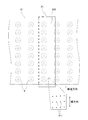
- FIG. 3 is a bottom view of one head 21.
- the conveyance belt 12 and the plurality of tablets 9 held on the conveyance belt 12 are indicated by a two-dot chain line.
- a plurality of ink nozzles 211 capable of ejecting ink droplets are provided on the ejection surface 210 which is the lower surface of the head 21.
- a plurality of ink nozzles 211 are two-dimensionally arranged on the lower surface of the head 21 in the transport direction and the width direction. The ink nozzles 211 are arranged with their positions shifted in the width direction.
- the positions in the width direction of the ink nozzles 211 can be brought closer to each other.
- the plurality of ink nozzles 211 may be arranged in a line along the width direction.
- the ink droplet ejection method may be a so-called thermal method in which the ink in the ink nozzle 211 is heated and expanded by energizing the heater.
- the drying mechanism 30 is a mechanism for drying the ink adhering to the surface of the tablet 9.
- the drying mechanism 30 is provided around the transport belt 12 at a position downstream of the printing unit 20 in the transport direction.
- a hot air supply mechanism that blows heated gas (hot air) toward the tablets 9 that are transported by the transport belt 12 is used.
- the ink adhering to the surface of the tablet 9 is dried by hot air and fixed on the surface of the tablet 9.
- the control unit 40 is a means for controlling the operation of each unit in the tablet printing apparatus 1.
- FIG. 4 is a block diagram showing the connection between the control unit 40 and each unit in the tablet printing apparatus 1.
- the control unit 40 is configured by a computer having a processor 41 such as a CPU, a memory 42 such as a RAM, and a storage unit 43 such as a hard disk drive.
- a computer program P for executing printing processing is installed in the storage unit 43.
- control unit 40 communicates with the transport motor 13, the suction mechanism 15, the blow mechanism 16, the four heads 21, the drying mechanism 30, the carry-in mechanism 51, and the carry-out mechanism 52 described above. Connected as possible.
- the control unit 40 is also communicably connected to a vertical movement mechanism 222, a horizontal movement mechanism 224, a liquid feed pump 733, and a blade movement mechanism 75, which will be described later.
- the control unit 40 temporarily reads the computer program P and data stored in the storage unit 43 into the memory 42, and the processor 41 performs arithmetic processing based on the computer program P, thereby controlling the operation of each unit described above. To do. Thereby, the printing process with respect to the plurality of tablets 9 and the cleaning process of the head 21 proceed.
- FIG. 5 is a side view of the printing unit 20 viewed from the position of the white arrow V in FIG.
- the internal space of the tablet printing apparatus 1 is divided into a printing area A1 and a cleaning area A2.
- the printing area A1 is an area where printing is performed on the tablet 9 while the tablet 9 is being transported by the tablet transport mechanism 10 described above.
- the cleaning area A2 is an area for waiting the head 21 before or after printing and cleaning the ejection surface 210 of the head 21.
- a partition wall 60 is provided between the printing area A1 and the cleaning area A2. The partition wall 60 extends parallel to the conveyance direction of the tablet 9 and perpendicular to the horizontal plane.
- the printing unit 20 has four heads 21. As shown in FIG. 5, the printing unit 20 includes a head moving mechanism 22 and a cleaning unit 23 for each head 21. That is, the printing unit 20 according to the present embodiment includes four heads 21, four head moving mechanisms 22 corresponding to the heads 21, and four cleaning units 23 corresponding to the heads 21.
- the head moving mechanism 22 is a mechanism for moving the head 21 between the printing area A1 and the cleaning area A2.
- the head moving mechanism 22 of this embodiment includes an arm 221, a vertical moving mechanism 222, a moving stage 223, and a horizontal moving mechanism 224.
- the arm 221 is a member extending in a direction parallel to the long side of the ejection surface 210 (hereinafter referred to as “front-rear direction”).
- the head 21 is fixed to the tip of the arm 221.
- the vertical movement mechanism 222 moves the arm 221 up and down in accordance with a command from the control unit 40. Thereby, as indicated by an arrow D1 in FIG. 5, the arm 221 and the head 21 move up and down as a unit.
- the vertical movement mechanism 222 is between at least two height positions, that is, a lowered position indicated by a solid line in FIG. 5 and an elevated position indicated by a two-dot chain line in FIG.
- the head 21 is moved up and down. In the lowered position, the ejection surface 210 of the head 21 comes into contact with the upper edge of the cap 71 described later. In the raised position, the ejection surface 210 of the head 21 moves away from the cap 71 upward.
- the vertical movement mechanism 222 is supported by the movement stage 223.
- the horizontal moving mechanism 224 moves the moving stage 223 in the front-rear direction.
- the moving stage 223, the vertical movement mechanism 222, the arm 221, and the head 21 move together in the front-rear direction.
- the head 21 and the arm 221 pass through the opening 61 provided in the partition wall 60.
- the opening 61 may be always opened, or may be opened only while the head 21 and the arm 221 pass.
- the horizontal movement mechanism 224 and the vertical movement mechanism 222 for example, a mechanism that converts the rotational movement of the motor into a straight movement through a ball screw is used.
- the horizontal movement mechanism 224 and the vertical movement mechanism 222 may be realized by other mechanisms such as a linear motor and an air cylinder.
- the cleaning unit 23 is a unit for cleaning the discharge surface 210 of the head 21 in the cleaning area A2.
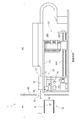
- FIG. 6 is a perspective view of the cleaning unit 23 as viewed obliquely from above.
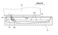
- FIG. 7 is a longitudinal sectional view of the cleaning unit 23. As shown in FIGS. 5 to 7, the cleaning unit 23 includes a cap 71, a cleaning nozzle 72, a cleaning liquid supply unit 73, a blade 74, and a blade moving mechanism 75.
- the cap 71 is a substantially rectangular parallelepiped casing having an open upper surface.
- the cap 71 is fixed at a predetermined position in the cleaning area A2.
- the head 21 evacuated to the cleaning area A ⁇ b> 2 is moved to the lowered position by the vertical movement mechanism 222.
- the ejection surface 210 of the head 21 contacts the rectangular upper end edge of the cap 71.
- a region other than the peripheral portion of the ejection surface 210 of the head 21 is covered with the cap 71.
- the plurality of ink nozzles 211 provided on the ejection surface 210 of the head 21 are all contained inside the rectangular upper end edge of the cap 71.
- the cleaning nozzle 72 is a member for discharging the cleaning liquid toward the discharge surface 210 of the head 21.
- the cleaning nozzle 72 is provided inside the cap 71.
- a straight tubular pipe nozzle extending in the front-rear direction is used for the cleaning nozzle 72. If the pipe nozzle is used, the cleaning liquid can be supplied to the ejection surface 210 of the head 21 over a wide range in the front-rear direction.
- the shape of the cleaning nozzle 72 may be other shapes such as a flat plate shape.
- a plurality of first discharge ports 721 are provided on the surface of the cleaning nozzle 72. The plurality of first discharge ports 721 are arranged at equal intervals in the front-rear direction. Each first discharge port 721 is open toward the discharge surface 210 of the head 21.
- the cleaning nozzle 72 of the present embodiment has a second discharge port 722 at the front end portion on the blade 74 side in the front-rear direction.
- the second discharge port 722 opens toward the blade 74 in the storage position described later.
- the cleaning nozzle 72 of the present embodiment has the first discharge port 721 and the second discharge port 722. As a result, the cleaning liquid can be directly discharged to the discharge surface 210 and the blade 74 of the head 21.
- the cleaning liquid supply unit 73 is a mechanism for supplying the cleaning liquid to the cleaning nozzle 72.
- the cleaning liquid supply unit 73 includes a cleaning liquid supply source 731, a liquid supply pipe 732, and a liquid supply pump 733.
- the cleaning liquid supply source 731 stores cleaning liquid before supply. For example, pure water is used as the cleaning liquid.
- the liquid supply pipe 732 connects the cleaning liquid supply source 731 and the cleaning nozzle 72 through a flow path.
- the liquid feed pump 733 is provided on the path of the liquid feed pipe 732. The liquid feed pump 733 operates based on a command from the control unit 40, and forms a liquid flow toward the cleaning nozzle 72 in the liquid feed pipe 732.
- the cleaning liquid is supplied from the cleaning liquid supply source 731 to the cleaning nozzle 72 through the liquid supply pipe 732.
- the cleaning liquid is discharged from the plurality of first discharge ports 721 of the cleaning nozzle 72 toward the discharge surface 210 of the head 21, and the cleaning liquid is discharged from the second discharge port 722 of the cleaning nozzle 72 toward the blade 74. Is done. Thereby, the fine powder and ink of the tablet 9 adhering to the ejection surface 210 of the head 21 and the surface of the blade 74 are washed away by the cleaning liquid.
- the blade 74 is a member for wiping off the cleaning liquid adhering to the ejection surface 210 of the head 21.
- a plate-like member made of flexible rubber or the like is used for the blade 74.
- the blade 74 has a blade base 741 and a blade tip 742.
- the blade base 741 is supported by a metal support member 743 that is higher in rigidity than the blade 74.
- the blade tip 742 is a part that contacts the ejection surface 210 of the head 21.
- the length of the blade tip portion 742 in the left-right direction (a direction perpendicular to the front-rear direction and the same hereinafter) is longer than the length of the blade base portion 741 in the left-right direction. That is, the blade 74 of this embodiment has a substantially T-shaped outer shape.
- a pair of side end portions 744 in the left-right direction of the blade tip portion 742 is located outside the inner edge of the cap 71.
- the blade moving mechanism 75 is a mechanism that rotates and moves the support member 743 and the blade 74.
- the blade moving mechanism 75 includes, for example, a drive source such as a motor and a power transmission mechanism that transmits the rotational motion of the motor to the support member 743.
- a drive source such as a motor
- a power transmission mechanism that transmits the rotational motion of the motor to the support member 743.
- the head 21 is raised and the ejection surface 210 of the head 21 is pulled away from the cap 71. Then, the blade 74 is rotated from the storage position to the standing position. In the standing position, the blade tip 742 projects upward from the upper end edge of the cap 71 and contacts the ejection surface 210 of the head 21. Thereafter, the head 21 at the raised position is moved in the front-rear direction by the horizontal movement mechanism 224. As a result, the cleaning liquid or the like adhering to the ejection surface 210 of the head 21 is wiped off by the blade tip 742.
- the length in the left-right direction of the blade tip 742 is larger than the distance in the left-right direction of the inner edge of the cap 71. For this reason, the blade tip 742 contacts a region of the ejection surface 210 of the head 21 that is wider than the inner edge of the cap 71. Thereby, the cleaning liquid adhering to the discharge surface 210 can be wiped off more efficiently. Further, fine powder of the tablet 9 that has flowed into the cleaning liquid tends to accumulate in the vicinity of the contact portion with the inner edge of the cap 71 on the ejection surface 210 of the head 21. In the present embodiment, the fine powder of the tablet 9 accumulated in the portion can be wiped off by the both end portions 744 of the blade tip portion 742. Thereby, the removal efficiency of the fine powder from the discharge surface 210 can be improved.
- the cap 71 of the present embodiment has blade storage holes 711 on the left and right inner surfaces, respectively.
- the pair of side end portions 744 of the blade tip portion 742 are stored in the pair of blade storage holes 711, respectively.
- the blade housing hole 711 is provided in the cap 71, the blade tip 742 can be housed inside the cap 71 without bending. Therefore, the temporal deformation of the blade tip 742 can be suppressed. That is, it is possible to suppress the shape of the blade tip portion 742 when standing up from changing with time.
- FIG. 8 is a flowchart showing a processing procedure during cleaning.
- FIG. 9 is a longitudinal sectional view showing the states of steps S2 and S9.
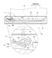
- FIG. 10 is a longitudinal sectional view showing the states of steps S5 and S12. The process described below proceeds by the control unit 40 controlling the operation of the vertical movement mechanism 222, horizontal movement mechanism 224, liquid feed pump 733, blade movement mechanism 75, and the like described above.
- the control unit 40 When cleaning the ejection surface 210 of the head 21, first, the control unit 40 operates the horizontal movement mechanism 224 to move the head 21 from the printing area A1 to the cleaning area A2. Next, the control unit 40 operates the vertical movement mechanism 222 to move the head 21 from the raised position to the lowered position (step S1). When the head 21 reaches the lowered position, the ejection surface 210 of the head 21 contacts the rectangular upper edge of the cap 71. As a result, the plurality of ink nozzles 211 provided on the ejection surface 210 of the head 21 are covered with the cap 71.
- the control unit 40 starts the operation of the liquid feed pump 733.
- the cleaning liquid is supplied from the cleaning liquid supply source 731 to the cleaning nozzle 72 through the liquid supply pipe 732.
- the cleaning liquid is discharged from the plurality of first discharge ports 721 of the cleaning nozzle 72 toward the discharge surface 210 of the head 21 (step S2, cleaning liquid supply process).
- the fine powder of the tablet 9 adhering to the ejection surface 210 of the head 21 is washed away by the cleaning liquid.
- the used cleaning liquid is discharged together with the fine powder of the tablet 9 through a drain port provided on the bottom surface of the cap 71.
- the liquid feed pump 733 may be continuously driven to discharge the cleaning liquid continuously from the cleaning nozzle 72.
- the liquid feeding pump 733 may be intermittently driven to intermittently discharge the cleaning liquid from the cleaning nozzle 72. If the strength of the cleaning liquid discharge is periodically changed as in the case of intermittent discharge, the fine powder of the tablet 9 adhering to the discharge surface 210 can be washed away more efficiently.
- the ejection surface 210 of the head 21 is coated with a water repellent film in order to eject ink droplets with high accuracy. If the blade 74 is slid on the discharge surface 210 while the fine powder of the tablet 9 is attached to the discharge surface 210, the water repellent film may be damaged by the fine powder, and the water repellent effect may be reduced. However, if the fine powder is removed from the ejection surface 210 with the cleaning liquid as in this embodiment, damage to the water-repellent film can be suppressed in the wiping process in steps S5 and S12 described later.
- step S2 the cleaning liquid is also discharged from the second discharge port 722 of the cleaning nozzle 72.
- the cleaning liquid discharged from the second discharge port 722 contacts the surface of the blade 74. Thereby, the surface of the blade 74 is cleaned. Details of the cleaning of the blade 74 will be described later.
- the control unit 40 stops the liquid feeding pump 733. Thereby, the discharge of the cleaning liquid from the cleaning nozzle 72 is stopped.
- control unit 40 operates the up-and-down moving mechanism 222 to move the head 21 from the lowered position to the raised position (step S3). As a result, the ejection surface 210 of the head 21 is pulled away from the upper end edge of the cap 71. Subsequently, the control unit 40 operates the blade moving mechanism 75 to rotate and move the blade 74 from the storage position to the standing position (step S4). As a result, the blade tip 742 is brought into contact with the ejection surface 210 of the head 21.
- control unit 40 operates the horizontal movement mechanism 224 to move the head 21 in the front-rear direction. Specifically, as shown in FIG. 10, the head 21 is moved horizontally toward the print area A1 side. As a result, the blade tip 742 slides relative to the ejection surface 210 of the head 21. As a result, the cleaning liquid adhering to the ejection surface 210 of the head 21 is wiped off by the blade tip 742 (step S5, wiping process).
- the control unit 40 When the wiping process is completed, the control unit 40 operates the blade moving mechanism 75 to rotate the blade 74 from the standing position to the storage position (step S6). As a result, the entire blade 74 is accommodated in the cap 71. Further, the control unit 40 operates the horizontal moving mechanism 224 to move the head 21 to the position above the cap 71 again. Then, the control unit 40 operates the vertical movement mechanism 222 to move the head 21 from the raised position to the lowered position (step S7). When the head 21 reaches the lowered position, the ejection surface 210 of the head 21 contacts the rectangular upper edge of the cap 71. As a result, the plurality of ink nozzles 211 provided on the ejection surface 210 of the head 21 are covered with the cap 71.
- control unit 40 operates the head 21 to continuously eject ink from the plurality of ink nozzles 211 of the head 21 (step S8, purge process). Thereby, in each ink nozzle 211, the clogging of the ink resulting from drying etc. is eliminated.
- control unit 40 stops ink ejection from each ink nozzle 211.
- the control unit 40 starts the operation of the liquid feed pump 733.
- the cleaning liquid is supplied from the cleaning liquid supply source 731 to the cleaning nozzle 72 through the liquid supply pipe 732.
- the cleaning liquid is discharged from the plurality of first discharge ports 721 of the cleaning nozzle 72 toward the discharge surface 210 of the head 21 (step S9, cleaning liquid supply process).
- the ink adhering to the ejection surface 210 of the head 21 is washed away by the cleaning liquid.
- the used cleaning liquid is discharged to the outside together with ink through a drain port provided on the bottom surface of the cap 71.
- step S9 the cleaning liquid is also discharged from the second discharge port 722 of the cleaning nozzle 72.
- the cleaning liquid discharged from the second discharge port 722 contacts the surface of the blade 74. Thereby, the surface of the blade 74 is cleaned. Details of the cleaning of the blade 74 will be described later.
- the control unit 40 stops the liquid feeding pump 733. Thereby, the discharge of the cleaning liquid from the cleaning nozzle 72 is stopped.
- control unit 40 operates the up-and-down moving mechanism 222 to move the head 21 from the lowered position to the raised position (step S10). As a result, the ejection surface 210 of the head 21 is pulled away from the upper end edge of the cap 71. Subsequently, the control unit 40 operates the blade moving mechanism 75 to rotate and move the blade 74 from the storage position to the standing position (step S11). As a result, the blade tip 742 is brought into contact with the ejection surface 210 of the head 21.
- control unit 40 operates the horizontal movement mechanism 224 to move the head 21 in the front-rear direction. Specifically, as shown in FIG. 10, the head 21 is moved horizontally toward the print area A1 side. As a result, the blade tip 742 slides relative to the ejection surface 210 of the head 21. As a result, the cleaning liquid adhering to the ejection surface 210 of the head 21 is wiped off by the blade tip 742 (step S12, wiping process).
- the control unit 40 When the wiping process is completed, the control unit 40 operates the blade moving mechanism 75 to rotate the blade 74 from the standing position to the storage position (step S13). As a result, the entire blade 74 is accommodated in the cap 71. Further, the control unit 40 operates the horizontal moving mechanism 224 to move the head 21 to the position above the cap 71 again. Then, the control unit 40 operates the vertical movement mechanism 222 to move the head 21 from the raised position to the lowered position (step S14). When the head 21 reaches the lowered position, the ejection surface 210 of the head 21 contacts the rectangular upper edge of the cap 71. As a result, the plurality of ink nozzles 211 provided on the ejection surface 210 of the head 21 are covered with the cap 71.
- the cleaning unit 23 of the present embodiment can wipe the cleaning liquid adhering to the ejection surface 210 with the blade 74 after ejecting the cleaning liquid to the ejection surface 210 of the head 21.
- the fine powder of the tablet 9 adhering to the discharge surface 210 can be removed efficiently.
- fine powder adhering to the ejection surface 210 can be removed by the cleaning unit 23. Therefore, ejection failure of ink droplets due to fine powder can be suppressed.
- the printing area A1 in which the tablets 9 are conveyed and the cleaning area A2 for cleaning the discharge surface 210 of the head 21 are partitioned by the partition wall 60. For this reason, even if dust or cleaning liquid mist is generated from the head moving mechanism 22 or the cleaning unit 23 arranged in the cleaning area A2, the dust or mist is unlikely to enter the printing area A1. Therefore, it is easy to keep the printing area A1 in a clean state with little dust and mist.
- a cleaning nozzle 72 and a blade 74 are provided inside the cap 71.
- the cleaning liquid is discharged from the cleaning nozzle 72 in a state where the blade 74 is housed in the cap 71.
- the discharged cleaning liquid not only the discharge surface 210 of the head 21 but also the surface of the blade 74 is cleaned by the discharged cleaning liquid. That is, the fine powder and ink of the tablet 9 adhering to the surface of the blade 74 are washed away by the cleaning liquid. Therefore, it is not necessary to separately provide a cleaning nozzle for discharging the cleaning liquid onto the discharge surface 210 of the head 21 and a cleaning nozzle for discharging the cleaning liquid onto the surface of the blade 74.
- the cleaning nozzle 72 of the present embodiment has a second discharge port 722 that opens toward the blade 74.
- the cleaning liquid is directly discharged from the second discharge port 722 toward the surface of the blade 74. Thereby, the fine powder and the ink of the tablet 9 adhering to the surface of the blade 74 are washed away efficiently.
- FIG. 11 is a perspective view of the blade 74 and the support member 743 in the storage position.
- the support member 743 of the present embodiment has a communication path 745.
- the cleaning liquid discharged from the second discharge port 722 of the cleaning nozzle 72 is supplied to the surface of the blade 74 through the communication path 745 as indicated by a broken line arrow in FIG.
- the communication path 745 is provided in the support member 743, the cleaning liquid can be supplied to the surface of the blade 74 more efficiently. Therefore, the fine powder and ink of the tablet 9 can be more efficiently removed from the surface of the blade 74.
- the support member 743 of the present embodiment has a pair of tapered surfaces 746 between the communication path 745 and the surface of the blade 74.
- the distance between the pair of tapered surfaces 746 gradually increases from the communication path 745 toward the surface of the blade 74. In this way, the spread of the cleaning liquid after passing through the communication path 745 is not easily blocked by the support member 743. Therefore, the cleaning liquid can be supplied more efficiently over a wide range of the surface of the blade 74.
- the blade 74 of the present embodiment is stored in an inclined position with respect to the horizontal plane, not in a horizontal position at the storage position. More specifically, of the both surfaces of the blade 74, the surface that contacts the ejection surface 210 during the wiping process is inclined so that it faces the cleaning nozzle 72 side. In this way, the cleaning liquid discharged from the cleaning nozzle 72 can be more efficiently supplied to the surface of the blade 74 that is easily contaminated. In addition, the supplied cleaning liquid flows down rapidly along the inclination of the blade 74. Therefore, fine powder and ink of the tablet 9 can be more efficiently removed from the surface of the blade 74.
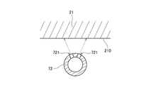
- the first discharge port 721 of the cleaning nozzle 72 is oriented perpendicular to the discharge surface 210 of the head 21.
- the first ejection port 721 may be oriented obliquely with respect to the ejection surface 210 of the head 21. This makes it difficult for the cleaning liquid discharged from the first discharge port 721 to enter the ink nozzle 211. Therefore, it is possible to prevent the cleaning liquid from being mixed with the undischarged ink in the ink nozzle 211.
- the position of the cap 71 is fixed, and the head 21 is lowered to bring the upper end edge of the cap 71 into contact with the ejection surface 210 of the head 21.
- the upper end edge of the cap 71 and the ejection surface 210 of the head 21 may be brought into contact with each other by providing a vertical movement mechanism in the cap 71 and raising the cap 71.
- the printing unit 20 is provided with the four heads 21.
- a head moving mechanism 22 and a cleaning unit 23 are provided for each of the four heads 21.
- the number of heads 21 included in the printing unit 20 may be 1 to 3, or 5 or more. Further, the number of head moving mechanisms 22 and cleaning units 23 is not limited to the above example.
- the tablet printing apparatus 1 may also include a printing unit that performs printing on the surface of the tablet 9 and a printing unit that performs printing on the back surface of the tablet 9.
- tablettes to be treated in the present invention include, for example, uncoated tablets, orally disintegrating tablets (OD tablets), film-coated tablets (FC tablets), sugar-coated tablets, scored tablets, etc., but are not necessarily tablets as pharmaceuticals. It is not limited to.
- the tablet printing apparatus of the present invention may perform printing on tablets as health foods or tablet confectionery such as ramune.
- the detailed configuration of the tablet printing apparatus 1 may be different from the drawings of the present application. Moreover, you may combine suitably each element which appeared in said embodiment and modification in the range which does not produce inconsistency.
Landscapes
- Health & Medical Sciences (AREA)
- Chemical & Material Sciences (AREA)
- Medicinal Chemistry (AREA)
- Pharmacology & Pharmacy (AREA)
- Life Sciences & Earth Sciences (AREA)
- Animal Behavior & Ethology (AREA)
- General Health & Medical Sciences (AREA)
- Public Health (AREA)
- Veterinary Medicine (AREA)
- Ink Jet (AREA)
- Medical Preparation Storing Or Oral Administration Devices (AREA)
Abstract
この錠剤印刷装置は、複数のインクノズルが配列された吐出面(210)を有するヘッド(21)と、ヘッド(21)の吐出面(210)を洗浄する洗浄ユニット(23)と、を有する。洗浄ユニット(23)は、吐出面(210)を覆うキャップ(71)と、キャップの内部に設けられた洗浄ノズル(72)およびブレード(74)と、を有する。ヘッド(21)の洗浄時には、まず、洗浄ノズル(72)から吐出面(210)に向けて洗浄液を吐出する。次に、吐出面(210)に付着した洗浄液を、ブレード(74)で拭き取る。これにより、吐出面(210)に付着した錠剤の微粉を、効率よく除去できる。また、洗浄ノズル(72)から吐出される洗浄液によって、ブレード(74)を洗浄することもできる。
Description
本発明は、錠剤の表面に印刷を行う錠剤印刷装置、および複数のインクノズルが配列されたヘッドの吐出面を洗浄する洗浄方法に関する。
医薬品の一形態である錠剤の表面には、製品を識別するための文字やコードが印字される。このような文字やコードは、刻印により印字される場合もあるが、刻印では視認性が低いという問題があった。特に、近年では、後発医薬品の普及により錠剤の種類が多様化している。このため、錠剤を識別しやすくするために、錠剤の表面にインクジェット方式で鮮明な印字を行う技術が注目されている。
特許文献1,2には、インクジェット方式で紙面上に印刷を行う従来の装置の例が記載されている。
インクジェット方式の錠剤印刷装置では、錠剤を搬送しつつ、ヘッドの吐出面に設けられた複数のノズルから錠剤に向けて、インクの液滴(以下、単に「インク滴」と称する)を吐出する。しかしながら、錠剤の搬送時には、搬送経路の周囲に錠剤の微粉が飛散する。この錠剤の微粉がヘッドの吐出面に付着すると、ノズルからインク滴を精度よく吐出することが困難となる。すなわち、錠剤を対象とする印刷装置では、錠剤の微粉によって、インク滴の吐出精度が低下しやすいという特有の課題がある。
ヘッドの吐出面から錠剤の微粉を除去するためには、例えば、可撓性を有する板状のブレードで、吐出面に付着した微粉を拭き取ることが考えられる。しかしながら、ヘッドの下面に微粉が付着した状態で、ブレードを摺動させると、微粉とのこすれによってヘッドの下面が損傷する場合がある。また、ブレードに微粉が付着するため、ブレード自体の洗浄も必要となる。
また、微粉の除去効率を高めるための1つの方法として、ブレードの先端部を広くすることが考えられる。しかしながら、ブレードを使用しないときに、ブレードの先端部を曲げた状態で収納すると、ブレードが徐々に変形する。そして、ブレードが変形すると、吐出面に対するブレードの接触面積が減り、ブレードによる拭き取りの効果が十分に得られない場合がある。
本発明は、このような事情に鑑みなされたものであり、ヘッドの吐出面に付着した錠剤の微粉を効率よく除去できる錠剤印刷装置および洗浄方法を提供することを目的とする。
上記課題を解決するため、本願の第1発明は、錠剤の表面に印刷を行う錠剤印刷装置であって、インク滴を吐出する複数のインクノズルが配列された吐出面を有するヘッドと、前記ヘッドの前記吐出面を洗浄する洗浄ユニットと、を備え、前記洗浄ユニットは、前記吐出面を覆うキャップと、前記吐出面に洗浄液を吐出する洗浄ノズルと、前記吐出面に付着した洗浄液を拭き取るブレードと、を有し、前記洗浄ノズルおよび前記ブレードが、前記キャップの内部に設けられている。
本願の第2発明は、第1発明の錠剤印刷装置であって、前記洗浄ユニットは、前記ブレードを、前記キャップ内に収納された収納位置と、前記キャップから突出した起立位置と、の間で移動させるブレード移動機構をさらに有する。
本願の第3発明は、第2発明の錠剤印刷装置であって、前記ブレードは、前記吐出面に接触する先端部を有し、前記先端部の一対の側端部は、前記キャップの内側縁よりも外側に位置する。
本願の第4発明は、第3発明の錠剤印刷装置であって、前記キャップは、前記先端部の前記一対の側端部を収納するブレード収納穴を有する。
本願の第5発明は、第2発明から第4発明までのいずれか1発明の錠剤印刷装置であって、前記収納位置において、前記ブレードは、水平面に対して傾斜した姿勢で収納される。
本願の第6発明は、第1発明から第5発明までのいずれか1発明の錠剤印刷装置であって、前記洗浄ノズルは、前記吐出面の長辺に沿って延びる管状のノズルである。
本願の第7発明は、第1発明から第6発明までのいずれか1発明の錠剤印刷装置であって、前記洗浄ノズルは、前記吐出面に向けて洗浄液を吐出する複数の第1吐出口を有し、前記複数の第1吐出口は、前記吐出面に対して斜めに向けられている。
本願の第8発明は、第1発明から第7発明までのいずれか1発明の錠剤印刷装置であって、前記洗浄ノズルは、前記ブレードへ向けて洗浄液を吐出する第2吐出口を有する。
本願の第9発明は、第1発明から第8発明までのいずれか1発明の錠剤印刷装置であって、前記洗浄ユニットは、前記ブレードを支持する支持部材をさらに有し、前記支持部材に連通路が設けられ、前記洗浄ノズルから吐出された洗浄液が、前記連通路を通って、前記ブレードへ供給される。
本願の第10発明は、第9発明の錠剤印刷装置であって、前記支持部材は、前記連通路から前記ブレードへ向かうにつれて徐々に間隔が拡がる一対のテーパ面を有する。
本願の第11発明は、第1発明から第10発明までのいずれか1発明の錠剤印刷装置であって、前記洗浄ユニットが配置される洗浄エリアと、錠剤に対して印刷が行われる印刷エリアと、前記洗浄エリアと前記印刷エリアとの間で、前記ヘッドを移動させるヘッド移動機構と、を備える。
本願の第12発明は、第11発明の錠剤印刷装置であって、前記洗浄エリアと前記印刷エリアとを仕切る隔壁をさらに備える。
本願の第13発明は、第1発明から第12発明までのいずれか1発明の錠剤印刷装置であって、前記ヘッドおよび前記洗浄ユニットを動作制御する制御部をさらに備え、前記制御部は、前記洗浄ノズルから前記吐出面に前記洗浄液を吐出する洗浄液供給処理と、前記洗浄液供給処理の後に、前記吐出面に付着した洗浄液を、前記ブレードで拭き取るワイプ処理と、を順次に実行する。
本願の第14発明は、第13発明の錠剤印刷装置であって、前記制御部は、前記洗浄液供給処理において、前記洗浄ノズルから、前記洗浄液を間欠吐出する。
本願の第15発明は、第13発明または第14発明の錠剤印刷装置であって、前記制御部は、前記ヘッドの複数の前記インクノズルからインクを吐出するパージ処理をさらに実行する。
本願の第16発明は、錠剤の表面に印刷を行う錠剤印刷装置であって、インク滴を吐出する複数のインクノズルが配列された吐出面を有するヘッドと、前記ヘッドの前記吐出面を洗浄する洗浄ユニットと、を備え、前記洗浄ユニットは、前記吐出面を覆うキャップと、前記吐出面に付着した洗浄液を拭き取るブレードと、前記ブレードを、前記キャップ内に収納された収納位置と、前記キャップから突出した起立位置と、の間で移動させるブレード移動機構を有し、前記ブレードは、前記吐出面に接触する先端部を有し、前記先端部の一対の側端部は、前記キャップの内側縁よりも外側に位置し、前記キャップは、前記先端部の前記一対の側端部を収納するブレード収納穴を有する。
本願の第17発明は、錠剤の表面に印刷を行う装置において、複数のインクノズルが配列されたヘッドの吐出面を洗浄する洗浄方法であって、a)前記吐出面をキャップで覆う工程と、b)前記キャップの内部に設けられた洗浄ノズルから、前記吐出面に洗浄液を吐出する工程と、c)前記吐出面を前記キャップから引き離す工程と、d)前記キャップの内部に設けられたブレードで、前記吐出面に付着した洗浄液を拭き取る工程と、を含む。
本願の第18発明は、錠剤の表面に印刷を行う装置において、複数のインクノズルが配列されたヘッドの吐出面を洗浄する洗浄方法であって、a)前記吐出面をキャップで覆う工程と、b)前記吐出面に洗浄液を吐出する工程と、c)前記吐出面を前記キャップから引き離す工程と、d)ブレードの先端部で、前記吐出面に付着した洗浄液を拭き取る工程と、を含み、前記ブレードは、前記キャップ内に収納された収納位置と、前記キャップから突出した起立位置と、の間で移動可能であり、前記先端部の一対の側端部は、前記キャップの内側縁よりも外側に位置し、前記キャップは、前記先端部の前記一対の側端部を収納するブレード収納穴を有する。
本願の第1発明~第15発明および第17発明によれば、ヘッドの吐出面に洗浄液を吐出した後、吐出面に付着した洗浄液を、ブレードで拭き取ることができる。これにより、吐出面に付着した錠剤の微粉を、効率よく除去できる。また、洗浄ノズルおよびブレードが、キャップの内部に設けられている。このため、洗浄ノズルから吐出される洗浄液によって、ブレードを洗浄することもできる。
特に、本願の第3発明によれば、吐出面のうち、キャップの内側縁よりも幅の広い領域に、ブレードの先端部が接触する。これにより、吐出面に付着した洗浄液を、より効率よく拭き取ることができる。また、キャップの内側縁付近に溜まった錠剤の微粉を、ブレードの先端部で拭き取ることができる。これにより、吐出面からの微粉の除去効率を、より高めることができる。
特に、本願の第4発明によれば、ブレードの先端部を曲げることなく、キャップの内部に収納できる。これにより、ブレードの経時変形を抑制できる。
特に、本願の第5発明によれば、キャップ内に収納されたブレードを、より効率よく洗浄できる。
特に、本願の第6発明によれば、吐出面の広い範囲に亘って、洗浄液を供給できる。
特に、本願の第7発明によれば、第1吐出口から吐出された洗浄液が、ヘッドのインクノズル内に入り込むことを抑制できる。
特に、本願の第8発明によれば、ブレードに直接洗浄液を供給できる。これにより、ブレードをより効率よく洗浄できる。
特に、本願の第9発明によれば、ブレードの表面に、より効率よく洗浄液を供給できる。
特に、本願の第10発明によれば、ブレードの表面に、より効率よく洗浄液を供給できる。
特に、本願の第11発明によれば、洗浄エリアと印刷エリアとを分離することで、錠剤が搬送される印刷エリアを、清浄な状態に保ちやすい。
特に、本願の第12発明によれば、錠剤が搬送される印刷エリアを、より清浄な状態に保ちやすい。
特に、本願の第14発明によれば、吐出面に付着した錠剤の微粉を、より効率よく洗い流すことができる。
特に、本願の第15発明によれば、インクノズルの詰まりを解消できる。
また、本願の第16発明および第18発明によれば、吐出面のうち、キャップの内側縁よりも幅の広い領域に、ブレードの先端部が接触する。これにより、吐出面に付着した洗浄液を、効率よく拭き取ることができる。また、ブレードの先端部を曲げることなく、キャップの内部に収納できる。これにより、ブレードの経時変形を抑制できる。
以下、本発明の実施形態について、図面を参照しつつ説明する。なお、以下の説明においては、複数の錠剤が搬送される方向を「搬送方向」と称し、搬送方向に対して垂直かつ水平な方向を「幅方向」と称する。
<1.錠剤印刷装置の全体構成>
図1は、本発明の一実施形態に係る錠剤印刷装置1の構成を示した図である。この錠剤印刷装置1は、医薬品である複数の錠剤9を搬送しながら、各錠剤9の表面に、製品名、製品コード、会社名、ロゴマーク等の画像を印刷する装置である。図1に示すように、本実施形態の錠剤印刷装置1は、錠剤搬送機構10、印刷部20、乾燥機構30、および制御部40を備えている。
図1は、本発明の一実施形態に係る錠剤印刷装置1の構成を示した図である。この錠剤印刷装置1は、医薬品である複数の錠剤9を搬送しながら、各錠剤9の表面に、製品名、製品コード、会社名、ロゴマーク等の画像を印刷する装置である。図1に示すように、本実施形態の錠剤印刷装置1は、錠剤搬送機構10、印刷部20、乾燥機構30、および制御部40を備えている。
錠剤搬送機構10は、複数の錠剤9を保持しつつ搬送する機構である。錠剤搬送機構10は、一対のプーリ11と、一対のプーリ11の間に掛け渡された環状の搬送ベルト12とを有する。錠剤印刷装置1に投入された複数の錠剤9は、振動フィーダや搬送ドラム等により構成される搬入機構51によって、等間隔に整列されるとともに、搬送ベルト12の外周面に供給される。一対のプーリ11の一方は、搬送用モータ13から得られる動力により回転する。これにより、搬送ベルト12が、図1中の矢印の方向に回動する。このとき、一対のプーリ11の他方は、搬送ベルト12の回動に伴い従動回転する。
図2は、錠剤搬送機構10の部分斜視図である。図2に示すように、搬送ベルト12には、複数の吸着孔14が設けられている。複数の吸着孔14は、搬送方向および幅方向に、等間隔に配列されている。また、図1に示すように、錠剤搬送機構10は、搬送ベルト12の内側の空間から気体を吸い出す吸引機構15を有する。吸引機構15を動作させると、搬送ベルト12の内側の空間が、大気圧よりも低い負圧となる。複数の錠剤9は、当該負圧によって、吸着孔14に吸着保持される。
このように、錠剤搬送機構10は、複数の錠剤9を、複数の吸着孔14に一定の間隔で保持しつつ、搬送ベルト12の回動によって、複数の錠剤9を搬送する。後述する4つのヘッド21の下方では、複数の錠剤9は、水平方向に搬送される。
また、図1に示すように、錠剤搬送機構10は、搬送ベルト12の内側に、ブロー機構16を有する。ブロー機構16を動作させると、搬送ベルト12の複数の吸着孔14のうち、搬出機構52に対向する吸着孔14のみが、大気圧よりも高い陽圧となる。これにより、当該吸着孔14における錠剤9の吸着が解除され、搬送ベルト12から搬出機構52へ、錠剤9が受け渡される。搬出機構52は、搬送ベルト12から受け渡された錠剤9を、例えば他の搬送ベルトによって、錠剤印刷装置1の外部へ搬出する。
印刷部20は、搬送ベルト12により搬送される錠剤9の表面に、インクジェット方式で画像を記録する部位である。図1に示すように、本実施形態の印刷部20は、4つのヘッド21を有する。4つのヘッド21は、搬送ベルト12の上方に位置し、錠剤9の搬送方向に沿って、一列に配置されている。4つのヘッド21は、錠剤9の表面に向けて、互いに異なる色(例えば、シアン、マゼンタ、イエロー、およびブラックの各色)のインク滴を吐出する。すると、これらの各色により形成される単色画像の重ね合わせによって、錠剤9の表面に、多色画像が記録される。なお、各ヘッド21から吐出されるインクには、食品衛生法で認可された原料により製造された可食性インクが使用される。
図3は、1つのヘッド21の下面図である。図3には、搬送ベルト12と、搬送ベルト12に保持された複数の錠剤9とが、二点鎖線で示されている。図3中に拡大して示したように、ヘッド21の下面である吐出面210には、インク滴を吐出可能な複数のインクノズル211が設けられている。本実施形態では、ヘッド21の下面に、複数のインクノズル211が、搬送方向および幅方向に二次元的に配列されている。各インクノズル211は、幅方向に位置をずらして配列されている。このように、複数のインクノズル211を二次元的に配置すれば、各インクノズル211の幅方向の位置を、互いに接近させることができる。ただし、複数のインクノズル211は、幅方向に沿って一列に配列されていてもよい。
インクノズル211からのインク滴の吐出方式には、例えば、圧電素子であるピエゾ素子に電圧を加えて変形させることにより、インクノズル211内のインクを加圧して吐出する、いわゆるピエゾ方式が用いられる。ただし、インク滴の吐出方式は、ヒータに通電してインクノズル211内のインクを加熱膨張させることにより吐出する、いわゆるサーマル方式であってもよい。
乾燥機構30は、錠剤9の表面に付着したインクを乾燥させる機構である。乾燥機構30は、搬送ベルト12の周囲の、印刷部20よりも搬送方向下流側の位置に設けられている。乾燥機構30には、例えば、搬送ベルト12により搬送される錠剤9へ向けて、加熱された気体(熱風)を吹き付ける、熱風供給機構が用いられる。錠剤9の表面に付着したインクは、熱風により乾燥して、錠剤9の表面に定着する。
制御部40は、錠剤印刷装置1内の各部を動作制御するための手段である。図4は、制御部40と、錠剤印刷装置1内の各部との接続を示したブロック図である。図4中に概念的に示したように、制御部40は、CPU等のプロセッサ41、RAM等のメモリ42、およびハードディスクドライブ等の記憶部43を有するコンピュータにより構成される。記憶部43内には、印刷処理を実行するためのコンピュータプログラムPが、インストールされている。
また、図4に示すように、制御部40は、上述した搬送用モータ13、吸引機構15、ブロー機構16、4つのヘッド21、乾燥機構30、搬入機構51、および搬出機構52と、それぞれ通信可能に接続されている。また、制御部40は、後述する上下移動機構222、水平移動機構224、送液ポンプ733、およびブレード移動機構75とも、通信可能に接続されている。制御部40は、記憶部43に記憶されたコンピュータプログラムPやデータをメモリ42に一時的に読み出し、当該コンピュータプログラムPに基づいて、プロセッサ41が演算処理を行うことにより、上記の各部を動作制御する。これにより、複数の錠剤9に対する印刷処理や、ヘッド21の洗浄処理が進行する。
<2.ヘッド移動機構および洗浄ユニットについて>
図5は、図1中の白抜き矢印Vの位置から見た印刷部20の側面図である。図5に示すように、この錠剤印刷装置1の内部空間は、印刷エリアA1と洗浄エリアA2とに分けられている。印刷エリアA1は、上述した錠剤搬送機構10により錠剤9を搬送しつつ、錠剤9に対して印刷を行うエリアである。洗浄エリアA2は、印刷前または印刷後にヘッド21を待機させるとともに、ヘッド21の吐出面210を洗浄するエリアである。印刷エリアA1と洗浄エリアA2との間には、両エリアを仕切る隔壁60が設けられている。隔壁60は、錠剤9の搬送方向と平行かつ水平面に対して垂直に広がっている。
図5は、図1中の白抜き矢印Vの位置から見た印刷部20の側面図である。図5に示すように、この錠剤印刷装置1の内部空間は、印刷エリアA1と洗浄エリアA2とに分けられている。印刷エリアA1は、上述した錠剤搬送機構10により錠剤9を搬送しつつ、錠剤9に対して印刷を行うエリアである。洗浄エリアA2は、印刷前または印刷後にヘッド21を待機させるとともに、ヘッド21の吐出面210を洗浄するエリアである。印刷エリアA1と洗浄エリアA2との間には、両エリアを仕切る隔壁60が設けられている。隔壁60は、錠剤9の搬送方向と平行かつ水平面に対して垂直に広がっている。
上述の通り、印刷部20は、4つのヘッド21を有する。また、図5に示すように、印刷部20は、ヘッド21ごとに、ヘッド移動機構22と、洗浄ユニット23とを有する。すなわち、本実施形態の印刷部20は、4つのヘッド21と、各ヘッド21に対応する4つのヘッド移動機構22と、各ヘッド21に対応する4つの洗浄ユニット23とを有する。
ヘッド移動機構22は、印刷エリアA1と洗浄エリアA2との間で、ヘッド21を移動させる機構である。本実施形態のヘッド移動機構22は、アーム221、上下移動機構222、移動ステージ223、および水平移動機構224を有する。アーム221は、吐出面210の長辺と平行な方向(以下「前後方向」と称する)に延びる部材である。ヘッド21は、アーム221の先端に固定されている。上下移動機構222は、制御部40からの指令に従って、アーム221を上下に移動させる。これにより、図5中の矢印D1のように、アーム221およびヘッド21が、一体として上下に移動する。
なお、上下移動機構222は、洗浄エリアA2において、図5中に実線で示した下降位置と、図5中に二点鎖線で示した上昇位置と、の少なくとも2つの高さ位置の間で、ヘッド21を昇降させる。下降位置では、ヘッド21の吐出面210が、後述するキャップ71の上端縁に接触する。上昇位置では、ヘッド21の吐出面210が、キャップ71から上方に離れる。
上下移動機構222は、移動ステージ223により支持されている。水平移動機構224は、移動ステージ223を、前後方向に移動させる。これにより、図5中の矢印D2のように、移動ステージ223、上下移動機構222、アーム221、およびヘッド21が、一体として前後方向に移動する。このとき、ヘッド21およびアーム221は、隔壁60に設けられた開口部61を通過する。開口部61は、常に開放されていてもよく、ヘッド21およびアーム221が通過する間のみ開放されるようになっていてもよい。
水平移動機構224および上下移動機構222には、例えば、モータの回転運動を、ボールねじを介して直進運動に変換する機構が用いられる。ただし、水平移動機構224および上下移動機構222は、リニアモータやエアシリンダなどの他の機構によって実現されるものであってもよい。
洗浄ユニット23は、洗浄エリアA2において、ヘッド21の吐出面210を洗浄するためのユニットである。図6は、洗浄ユニット23を斜め上方から見た斜視図である。図7は、洗浄ユニット23の縦断面図である。図5~図7に示すように、洗浄ユニット23は、キャップ71、洗浄ノズル72、洗浄液供給部73、ブレード74、およびブレード移動機構75を有する。
キャップ71は、上面が開放された略直方体状の筐体である。キャップ71は、洗浄エリアA2内の所定の位置に、固定されている。ヘッド21の吐出面210を洗浄するときには、洗浄エリアA2へ退避させたヘッド21を、上下移動機構222によって下降位置へ移動させる。これにより、ヘッド21の吐出面210が、キャップ71の矩形状の上端縁に接触する。その結果、ヘッド21の吐出面210のうち、周縁部以外の領域が、キャップ71に覆われる。ヘッド21の吐出面210に設けられた複数のインクノズル211は、全て、キャップ71の矩形状の上端縁の内側に収まる。
洗浄ノズル72は、ヘッド21の吐出面210に向けて、洗浄液を吐出するための部材である。洗浄ノズル72は、キャップ71の内部に設けられている。本実施形態では、洗浄ノズル72に、前後方向に延びる直管状のパイプノズルが用いられている。パイプノズルを用いれば、ヘッド21の吐出面210に対して、前後方向の広い範囲に亘って、洗浄液を供給できる。ただし、洗浄ノズル72の形状は、平板状などの他の形状であってもよい。洗浄ノズル72の表面には、複数の第1吐出口721が設けられている。複数の第1吐出口721は、前後方向に等間隔に配列されている。また、各第1吐出口721は、ヘッド21の吐出面210に向けて開口している。
また、本実施形態の洗浄ノズル72は、前後方向のブレード74側の先端部に、第2吐出口722を有する。第2吐出口722は、後述する収納位置のブレード74に向けて、開口している。このように、本実施形態の洗浄ノズル72は、第1吐出口721と第2吐出口722とを有する。これにより、ヘッド21の吐出面210とブレード74とに、それぞれ直接的に洗浄液を吐出することができる。
洗浄液供給部73は、洗浄ノズル72に対して洗浄液を供給するための機構である。図5に示すように、洗浄液供給部73は、洗浄液供給源731、送液配管732、および送液ポンプ733を有する。洗浄液供給源731には、供給前の洗浄液が貯留されている。洗浄液には、例えば純水が用いられる。送液配管732は、洗浄液供給源731と洗浄ノズル72とを流路接続する。送液ポンプ733は、送液配管732の経路上に設けられている。送液ポンプ733は、制御部40からの指令に基づいて動作し、送液配管732内に、洗浄ノズル72側へ向かう液流を形成する。
送液ポンプ733を駆動させると、洗浄液供給源731から送液配管732を通って洗浄ノズル72へ、洗浄液が供給される。そして、洗浄ノズル72の複数の第1吐出口721からヘッド21の吐出面210へ向けて、洗浄液が吐出されるとともに、洗浄ノズル72の第2吐出口722からブレード74へ向けて、洗浄液が吐出される。これにより、ヘッド21の吐出面210およびブレード74の表面に付着した錠剤9の微粉およびインクが、洗浄液によって洗い流される。
ブレード74は、ヘッド21の吐出面210に付着した洗浄液を、拭き取るための部材である。ブレード74には、例えば、可撓性を有するゴムなどで形成された板状の部材が用いられる。図6および図7に示すように、ブレード74は、ブレード基部741とブレード先端部742とを有する。ブレード基部741は、ブレード74よりも剛性の高い金属製の支持部材743によって、支持される。ブレード先端部742は、ヘッド21の吐出面210に接触する部位である。ブレード先端部742の左右方向(前後方向に対して垂直かつ水平な方向。以下同じ)の長さは、ブレード基部741の左右方向の長さよりも長い。すなわち、本実施形態のブレード74は、略T字状の外形を有する。ブレード先端部742の左右方向の一対の側端部744は、キャップ71の内側縁よりも外側に位置する。
ブレード移動機構75は、支持部材743およびブレード74を、回転移動させる機構である。ブレード移動機構75は、例えば、モータ等の駆動源と、モータの回転運動を支持部材743に伝達する動力伝達機構とを有する。ブレード移動機構75を動作させると、ブレード74は、図7中に実線で示した収納位置と、図7中に二点鎖線で示した起立位置との間で、回転移動する。ヘッド21を下降させて、ヘッド21とキャップ71とを接触させるときには、ブレード74は、収納位置に配置される。収納位置では、ブレード74の全体が、キャップ71の内部に収納される。
一方、ブレード74による洗浄液の拭き取りを行うときには、ヘッド21を上昇させて、ヘッド21の吐出面210を、キャップ71から引き離す。そして、ブレード74を収納位置から起立位置へ回転移動させる。起立位置では、ブレード先端部742が、キャップ71の上端縁よりも上方へ突出し、ヘッド21の吐出面210に接触する。その後、上昇位置のヘッド21を、水平移動機構224により前後方向に移動させる。これにより、ヘッド21の吐出面210に付着した洗浄液等が、ブレード先端部742によって拭き取られる。
上述の通り、ブレード先端部742の左右方向の長さは、キャップ71の内側縁の左右方向の間隔よりも大きい。このため、ブレード先端部742は、ヘッド21の吐出面210のうち、キャップ71の内側縁よりも幅の広い領域に接触する。これにより、吐出面210に付着した洗浄液を、より効率よく拭き取ることができる。また、ヘッド21の吐出面210のうち、キャップ71の内側縁との接触部付近には、洗浄液に流された錠剤9の微粉が溜まりやすい。本実施形態では、当該部分に溜まった錠剤9の微粉を、ブレード先端部742の両側端部744によって、拭き取ることができる。これにより、吐出面210からの微粉の除去効率を、高めることができる。
また、図6および図7に示すように、本実施形態のキャップ71は、左右の内側面に、それぞれブレード収納穴711を有する。ブレード74が収納位置に配置されたときには、ブレード先端部742の一対の側端部744が、一対のブレード収納穴711内に、それぞれ収納される。このように、キャップ71にブレード収納穴711を設ければ、ブレード先端部742を、曲げることなくキャップ71の内部に収納できる。したがって、ブレード先端部742の経時変形を抑制できる。すなわち、ブレード先端部742の起立時の形状が、時間の経過とともに変化することを抑制できる。
<3.洗浄時の処理手順について>
続いて、上述した錠剤印刷装置1において、ヘッド21の吐出面210を洗浄するときの動作について説明する。図8は、洗浄時の処理手順を示すフローチャートである。図9は、ステップS2およびS9の状態を示す縦断面図である。図10は、ステップS5およびS12の状態を示す縦断面図である。以下に説明する処理は、制御部40が、上述した上下移動機構222、水平移動機構224、送液ポンプ733、ブレード移動機構75等を動作制御することによって進行する。
続いて、上述した錠剤印刷装置1において、ヘッド21の吐出面210を洗浄するときの動作について説明する。図8は、洗浄時の処理手順を示すフローチャートである。図9は、ステップS2およびS9の状態を示す縦断面図である。図10は、ステップS5およびS12の状態を示す縦断面図である。以下に説明する処理は、制御部40が、上述した上下移動機構222、水平移動機構224、送液ポンプ733、ブレード移動機構75等を動作制御することによって進行する。
ヘッド21の吐出面210を洗浄するときには、まず、制御部40が、水平移動機構224を動作させて、ヘッド21を、印刷エリアA1から洗浄エリアA2へ移動させる。次に、制御部40が、上下移動機構222を動作させて、ヘッド21を、上昇位置から下降位置へ移動させる(ステップS1)。ヘッド21が下降位置に到達すると、ヘッド21の吐出面210が、キャップ71の矩形状の上端縁に接触する。その結果、ヘッド21の吐出面210に設けられた複数のインクノズル211が、キャップ71に覆われる。
続いて、制御部40は、送液ポンプ733の動作を開始させる。これにより、洗浄液供給源731から送液配管732を通って洗浄ノズル72へ、洗浄液が供給される。そして、図9のように、洗浄ノズル72の複数の第1吐出口721からヘッド21の吐出面210へ向けて、洗浄液が吐出される(ステップS2,洗浄液供給処理)。これにより、ヘッド21の吐出面210に付着した錠剤9の微粉が、洗浄液によって洗い流される。使用後の洗浄液は、錠剤9の微粉とともに、キャップ71の底面に設けられた排液口を通って、外部へ排出される。
ステップS2では、送液ポンプ733を連続的に駆動させて、洗浄ノズル72から連続的に洗浄液を吐出してもよい。あるいは、送液ポンプ733を断続的に駆動させて、洗浄ノズル72から洗浄液を間欠吐出させてもよい。間欠吐出のように、洗浄液の吐出の強さを周期的に変化させれば、吐出面210に付着した錠剤9の微粉を、より効率よく洗い流すことができる。
ヘッド21の吐出面210には、インク滴を精度よく吐出するために、撥水膜のコーティングが施されている。仮に、吐出面210に錠剤9の微粉が付着した状態で、吐出面210にブレード74を摺動させると、微粉によって撥水膜が損傷し、撥水効果が低減する虞がある。しかしながら、本実施形態のように、洗浄液によって、吐出面210から微粉を除去しておけば、後述するステップS5およびS12のワイプ処理において、撥水膜の損傷を抑制できる。
なお、ステップS2では、洗浄ノズル72の第2吐出口722からも、洗浄液が吐出される。第2吐出口722から吐出された洗浄液は、ブレード74の表面に接触する。これにより、ブレード74の表面が洗浄される。ブレード74の洗浄の詳細については、後述する。
洗浄液の吐出開始後、予め設定された時間が経過すると、制御部40は、送液ポンプ733を停止させる。これにより、洗浄ノズル72からの洗浄液の吐出を停止する。
次に、制御部40は、上下移動機構222を動作させて、ヘッド21を、下降位置から上昇位置へ移動させる(ステップS3)。これにより、ヘッド21の吐出面210が、キャップ71の上端縁から引き離される。続いて、制御部40は、ブレード移動機構75を動作させて、ブレード74を、収納位置から起立位置へ回転移動させる(ステップS4)。これにより、ブレード先端部742を、ヘッド21の吐出面210に接触させる。
その後、制御部40は、水平移動機構224を動作させて、ヘッド21を前後方向に移動させる。具体的には、図10のように、ヘッド21を、印刷エリアA1側へ向けて、水平に移動させる。これにより、ヘッド21の吐出面210に対して、ブレード先端部742が、相対的に摺動する。その結果、ヘッド21の吐出面210に付着した洗浄液が、ブレード先端部742によって拭き取られる(ステップS5,ワイプ処理)。
ワイプ処理が完了すると、制御部40は、ブレード移動機構75を動作させて、ブレード74を、起立位置から収納位置へ回転移動させる(ステップS6)。これにより、ブレード74の全体を、キャップ71の内部に収納する。また、制御部40は、水平移動機構224を動作させて、ヘッド21を、再びキャップ71の上方位置へ移動させる。そして、制御部40は、上下移動機構222を動作させて、ヘッド21を、上昇位置から下降位置へ移動させる(ステップS7)。ヘッド21が下降位置に到達すると、ヘッド21の吐出面210が、キャップ71の矩形状の上端縁に接触する。その結果、ヘッド21の吐出面210に設けられた複数のインクノズル211が、キャップ71に覆われる。
続いて、制御部40は、ヘッド21を動作させて、ヘッド21の複数のインクノズル211から、連続的にインクを吐出する(ステップS8,パージ処理)。これにより、各インクノズル211において、乾燥等に起因するインクの詰まりが解消される。インクの吐出開始後、予め設定された時間が経過すると、制御部40は、各インクノズル211からのインクの吐出を停止させる。
続いて、制御部40は、送液ポンプ733の動作を開始させる。これにより、洗浄液供給源731から送液配管732を通って洗浄ノズル72へ、洗浄液が供給される。そして、図9のように、洗浄ノズル72の複数の第1吐出口721からヘッド21の吐出面210へ向けて、洗浄液が吐出される(ステップS9,洗浄液供給処理)。これにより、ヘッド21の吐出面210に付着したインクが、洗浄液によって洗い流される。使用後の洗浄液は、インクとともに、キャップ71の底面に設けられた排液口を通って、外部へ排出される。
なお、ステップS9では、洗浄ノズル72の第2吐出口722からも、洗浄液が吐出される。第2吐出口722から吐出された洗浄液は、ブレード74の表面に接触する。これにより、ブレード74の表面が洗浄される。ブレード74の洗浄の詳細については、後述する。
洗浄液の吐出開始後、予め設定された時間が経過すると、制御部40は、送液ポンプ733を停止させる。これにより、洗浄ノズル72からの洗浄液の吐出を停止する。
次に、制御部40は、上下移動機構222を動作させて、ヘッド21を、下降位置から上昇位置へ移動させる(ステップS10)。これにより、ヘッド21の吐出面210が、キャップ71の上端縁から引き離される。続いて、制御部40は、ブレード移動機構75を動作させて、ブレード74を、収納位置から起立位置へ回転移動させる(ステップS11)。これにより、ブレード先端部742を、ヘッド21の吐出面210に接触させる。
その後、制御部40は、水平移動機構224を動作させて、ヘッド21を前後方向に移動させる。具体的には、図10のように、ヘッド21を、印刷エリアA1側へ向けて、水平に移動させる。これにより、ヘッド21の吐出面210に対して、ブレード先端部742が、相対的に摺動する。その結果、ヘッド21の吐出面210に付着した洗浄液が、ブレード先端部742によって拭き取られる(ステップS12,ワイプ処理)。
ワイプ処理が完了すると、制御部40は、ブレード移動機構75を動作させて、ブレード74を、起立位置から収納位置へ回転移動させる(ステップS13)。これにより、ブレード74の全体を、キャップ71の内部に収納する。また、制御部40は、水平移動機構224を動作させて、ヘッド21を、再びキャップ71の上方位置へ移動させる。そして、制御部40は、上下移動機構222を動作させて、ヘッド21を、上昇位置から下降位置へ移動させる(ステップS14)。ヘッド21が下降位置に到達すると、ヘッド21の吐出面210が、キャップ71の矩形状の上端縁に接触する。その結果、ヘッド21の吐出面210に設けられた複数のインクノズル211が、キャップ71に覆われる。
このように、本実施形態の洗浄ユニット23は、ヘッド21の吐出面210に洗浄液を吐出した後、吐出面210に付着した洗浄液を、ブレード74で拭き取ることができる。これにより、吐出面210に付着した錠剤9の微粉を、効率よく除去できる。特に、錠剤印刷装置1において搬送される錠剤9が、粉体を圧縮形成したものである場合には、錠剤9の表面から微粉が発生しやすく、その微粉がヘッド21の吐出面210に付着しやすい。しかしながら、本実施形態の錠剤印刷装置1では、吐出面210に付着した微粉を、洗浄ユニット23により除去することができる。したがって、微粉によるインク滴の吐出不良を抑制できる。
また、本実施形態の錠剤印刷装置1では、錠剤9が搬送される印刷エリアA1と、ヘッド21の吐出面210を洗浄する洗浄エリアA2とが、隔壁60によって仕切られている。このため、洗浄エリアA2に配置されたヘッド移動機構22や洗浄ユニット23から、仮に粉塵や洗浄液のミストが発生したとしても、その粉塵やミストが、印刷エリアA1へ侵入しにくい。したがって、印刷エリアA1を、粉塵およびミストが少ない清浄な状態に保ちやすい。
<4.ブレードの洗浄について>
この錠剤印刷装置1では、洗浄ノズル72およびブレード74が、キャップ71の内部に設けられている。上述したステップS2およびステップS9では、ブレード74をキャップ71内に収納した状態で、洗浄ノズル72から洗浄液を吐出する。このため、吐出された洗浄液によって、ヘッド21の吐出面210だけではなく、ブレード74の表面も洗浄される。すなわち、ブレード74の表面に付着した錠剤9の微粉およびインクが、洗浄液によって洗い流される。したがって、ヘッド21の吐出面210に洗浄液を吐出するための洗浄ノズルと、ブレード74の表面に洗浄液を吐出するための洗浄ノズルとを、別個に設ける必要はない。
この錠剤印刷装置1では、洗浄ノズル72およびブレード74が、キャップ71の内部に設けられている。上述したステップS2およびステップS9では、ブレード74をキャップ71内に収納した状態で、洗浄ノズル72から洗浄液を吐出する。このため、吐出された洗浄液によって、ヘッド21の吐出面210だけではなく、ブレード74の表面も洗浄される。すなわち、ブレード74の表面に付着した錠剤9の微粉およびインクが、洗浄液によって洗い流される。したがって、ヘッド21の吐出面210に洗浄液を吐出するための洗浄ノズルと、ブレード74の表面に洗浄液を吐出するための洗浄ノズルとを、別個に設ける必要はない。
特に、本実施形態の洗浄ノズル72は、ブレード74に向けて開口した第2吐出口722を有する。上述したステップS2およびステップS9では、第2吐出口722からブレード74の表面へ向けて、直接的に洗浄液が吐出される。これにより、ブレード74の表面に付着した錠剤9の微粉やインクが、効率よく洗い流される。
図11は、収納位置におけるブレード74および支持部材743の斜視図である。図11に示すように、本実施形態の支持部材743は、連通路745を有する。洗浄ノズル72の第2吐出口722から吐出された洗浄液は、図11中の破線矢印のように、連通路745を通って、ブレード74の表面に供給される。このように、支持部材743に連通路745を設ければ、ブレード74の表面に、より効率よく洗浄液を供給できる。したがって、ブレード74の表面から、錠剤9の微粉およびインクを、より効率よく除去できる。
また、本実施形態の支持部材743は、連通路745とブレード74の表面との間に、一対のテーパ面746を有する。一対のテーパ面746の間隔は、連通路745からブレード74の表面へ向かうにつれて、徐々に拡がる。このようにすれば、連通路745を通過した後の洗浄液の拡がりが、支持部材743に遮られにくくなる。したがって、ブレード74の表面の広い範囲に、洗浄液をより効率よく供給できる。
また、図7、図9、および図11に示すように、本実施形態のブレード74は、収納位置において、水平姿勢ではなく、水平面に対して傾斜した姿勢で収納される。より具体的には、ブレード74の両面のうち、ワイプ処理時に吐出面210と接触する面が、洗浄ノズル72側を向くような傾斜姿勢となる。このようにすれば、洗浄ノズル72から吐出された洗浄液を、ブレード74の汚れやすい面に、より効率よく供給できる。また、供給された洗浄液は、ブレード74の傾斜に沿って、速やかに下方へ流れ落ちる。したがって、ブレード74の表面から、錠剤9の微粉やインクを、より効率よく除去できる。
<5.変形例>
以上、本発明の主たる実施形態について説明したが、本発明は、上記の実施形態に限定されるものではない。
以上、本発明の主たる実施形態について説明したが、本発明は、上記の実施形態に限定されるものではない。
上記の実施形態では、洗浄ノズル72の第1吐出口721が、ヘッド21の吐出面210に対して垂直に向けられていた。しかしながら、図12のように、第1吐出口721は、ヘッド21の吐出面210に対して斜めに向けられていてもよい。このようにすれば、第1吐出口721から吐出された洗浄液が、インクノズル211内に入り込みにくくなる。したがって、インクノズル211内の未吐出のインクに、洗浄液が混合されることを抑制できる。
また、上記の実施形態では、キャップ71の位置が固定され、ヘッド21が下降することによって、キャップ71の上端縁とヘッド21の吐出面210とを接触させていた。しかしながら、キャップ71に上下移動機構を設け、キャップ71を上昇させることによって、キャップ71の上端縁とヘッド21の吐出面210とを接触させてもよい。
また、上記の実施形態では、印刷部20に、4つのヘッド21が設けられていた。そして、4つのヘッド21の各々に対して、ヘッド移動機構22と洗浄ユニット23とが、設けられていた。しかしながら、印刷部20に含まれるヘッド21の数は、1~3つであってもよく、5つ以上であってもよい。また、ヘッド移動機構22および洗浄ユニット23の数も、上記の例には限定されない。また、錠剤印刷装置1は、錠剤9の表面に印刷を行う印刷部と、錠剤9の裏面に印刷を行う印刷部と、を備えていてもよい。
また、本発明において処理対象となる「錠剤」は、例えば、素錠、口腔内崩壊錠(OD錠)、フィルムコーティング錠(FC錠)、糖衣錠、割線錠などを含むが、必ずしも医薬品としての錠剤には限定されない。本発明の錠剤印刷装置は、健康食品としての錠剤や、ラムネ等の錠菓に対して、印刷を行うものであってもよい。
また、錠剤印刷装置1の細部の構成については、本願の各図と相違していてもよい。また、上記の実施形態や変形例に登場した各要素を、矛盾が生じない範囲で、適宜に組み合わせてもよい。
1 錠剤印刷装置
9 錠剤
10 錠剤搬送機構
12 搬送ベルト
20 印刷部
21 ヘッド
22 ヘッド移動機構
23 洗浄ユニット
30 乾燥機構
40 制御部
60 隔壁
61 開口部
71 キャップ
72 洗浄ノズル
73 洗浄液供給部
74 ブレード
75 ブレード移動機構
210 吐出面
211 インクノズル
221 アーム
222 上下移動機構
223 移動ステージ
224 水平移動機構
711 ブレード収納穴
721 第1吐出口
722 第2吐出口
731 洗浄液供給源
732 送液配管
733 送液ポンプ
741 ブレード基部
742 ブレード先端部
743 支持部材
744 側端部
745 連通路
746 テーパ面
A1 印刷エリア
A2 洗浄エリア
9 錠剤
10 錠剤搬送機構
12 搬送ベルト
20 印刷部
21 ヘッド
22 ヘッド移動機構
23 洗浄ユニット
30 乾燥機構
40 制御部
60 隔壁
61 開口部
71 キャップ
72 洗浄ノズル
73 洗浄液供給部
74 ブレード
75 ブレード移動機構
210 吐出面
211 インクノズル
221 アーム
222 上下移動機構
223 移動ステージ
224 水平移動機構
711 ブレード収納穴
721 第1吐出口
722 第2吐出口
731 洗浄液供給源
732 送液配管
733 送液ポンプ
741 ブレード基部
742 ブレード先端部
743 支持部材
744 側端部
745 連通路
746 テーパ面
A1 印刷エリア
A2 洗浄エリア
Claims (18)
- 錠剤の表面に印刷を行う錠剤印刷装置であって、
インク滴を吐出する複数のインクノズルが配列された吐出面を有するヘッドと、
前記ヘッドの前記吐出面を洗浄する洗浄ユニットと、
を備え、
前記洗浄ユニットは、
前記吐出面を覆うキャップと、
前記吐出面に洗浄液を吐出する洗浄ノズルと、
前記吐出面に付着した洗浄液を拭き取るブレードと、
を有し、
前記洗浄ノズルおよび前記ブレードが、前記キャップの内部に設けられている錠剤印刷装置。 - 請求項1に記載の錠剤印刷装置であって、
前記洗浄ユニットは、
前記ブレードを、前記キャップ内に収納された収納位置と、前記キャップから突出した起立位置と、の間で移動させるブレード移動機構
をさらに有する錠剤印刷装置。 - 請求項2に記載の錠剤印刷装置であって、
前記ブレードは、前記吐出面に接触する先端部を有し、
前記先端部の一対の側端部は、前記キャップの内側縁よりも外側に位置する錠剤印刷装置。 - 請求項3に記載の錠剤印刷装置であって、
前記キャップは、
前記先端部の前記一対の側端部を収納するブレード収納穴
を有する錠剤印刷装置。 - 請求項2から請求項4までのいずれか1項に記載の錠剤印刷装置であって、
前記収納位置において、前記ブレードは、水平面に対して傾斜した姿勢で収納される錠剤印刷装置。 - 請求項1から請求項5までのいずれか1項に記載の錠剤印刷装置であって、
前記洗浄ノズルは、前記吐出面の長辺に沿って延びる管状のノズルである錠剤印刷装置。 - 請求項1から請求項6までのいずれか1項に記載の錠剤印刷装置であって、
前記洗浄ノズルは、前記吐出面に向けて洗浄液を吐出する複数の第1吐出口を有し、
前記複数の第1吐出口は、前記吐出面に対して斜めに向けられている錠剤印刷装置。 - 請求項1から請求項7までのいずれか1項に記載の錠剤印刷装置であって、
前記洗浄ノズルは、前記ブレードへ向けて洗浄液を吐出する第2吐出口を有する錠剤印刷装置。 - 請求項1から請求項8までのいずれか1項に記載の錠剤印刷装置であって、
前記洗浄ユニットは、前記ブレードを支持する支持部材をさらに有し、
前記支持部材に連通路が設けられ、
前記洗浄ノズルから吐出された洗浄液が、前記連通路を通って、前記ブレードへ供給される錠剤印刷装置。 - 請求項9に記載の錠剤印刷装置であって、
前記支持部材は、前記連通路から前記ブレードへ向かうにつれて徐々に間隔が拡がる一対のテーパ面を有する錠剤印刷装置。 - 請求項1から請求項10までのいずれか1項に記載の錠剤印刷装置であって、
前記洗浄ユニットが配置される洗浄エリアと、
錠剤に対して印刷が行われる印刷エリアと、
前記洗浄エリアと前記印刷エリアとの間で、前記ヘッドを移動させるヘッド移動機構と、
を備える錠剤印刷装置。 - 請求項11に記載の錠剤印刷装置であって、
前記洗浄エリアと前記印刷エリアとを仕切る隔壁
をさらに備える錠剤印刷装置。 - 請求項1から請求項12までのいずれか1項に記載の錠剤印刷装置であって、
前記ヘッドおよび前記洗浄ユニットを動作制御する制御部
をさらに備え、
前記制御部は、
前記洗浄ノズルから前記吐出面に前記洗浄液を吐出する洗浄液供給処理と、
前記洗浄液供給処理の後に、前記吐出面に付着した洗浄液を、前記ブレードで拭き取るワイプ処理と、
を順次に実行する錠剤印刷装置。 - 請求項13に記載の錠剤印刷装置であって、
前記制御部は、前記洗浄液供給処理において、前記洗浄ノズルから、前記洗浄液を間欠吐出する錠剤印刷装置。 - 請求項13または請求項14に記載の錠剤印刷装置であって、
前記制御部は、
前記ワイプ処理の後に、前記ヘッドの複数の前記インクノズルからインクを吐出するパージ処理
をさらに実行する錠剤印刷装置。 - 錠剤の表面に印刷を行う錠剤印刷装置であって、
インク滴を吐出する複数のインクノズルが配列された吐出面を有するヘッドと、
前記ヘッドの前記吐出面を洗浄する洗浄ユニットと、
を備え、
前記洗浄ユニットは、
前記吐出面を覆うキャップと、
前記吐出面に付着した洗浄液を拭き取るブレードと、
前記ブレードを、前記キャップ内に収納された収納位置と、前記キャップから突出した起立位置と、の間で移動させるブレード移動機構
を有し、
前記ブレードは、前記吐出面に接触する先端部を有し、
前記先端部の一対の側端部は、前記キャップの内側縁よりも外側に位置し、
前記キャップは、
前記先端部の前記一対の側端部を収納するブレード収納穴
を有する錠剤印刷装置。 - 錠剤の表面に印刷を行う装置において、複数のインクノズルが配列されたヘッドの吐出面を洗浄する洗浄方法であって、
a)前記吐出面をキャップで覆う工程と、
b)前記キャップの内部に設けられた洗浄ノズルから、前記吐出面に洗浄液を吐出する工程と、
c)前記吐出面を前記キャップから引き離す工程と、
d)前記キャップの内部に設けられたブレードで、前記吐出面に付着した洗浄液を拭き取る工程と、
を含む洗浄方法。 - 錠剤の表面に印刷を行う装置において、複数のインクノズルが配列されたヘッドの吐出面を洗浄する洗浄方法であって、
a)前記吐出面をキャップで覆う工程と、
b)前記吐出面に洗浄液を吐出する工程と、
c)前記吐出面を前記キャップから引き離す工程と、
d)ブレードの先端部で、前記吐出面に付着した洗浄液を拭き取る工程と、
を含み、
前記ブレードは、前記キャップ内に収納された収納位置と、前記キャップから突出した起立位置と、の間で移動可能であり、
前記先端部の一対の側端部は、前記キャップの内側縁よりも外側に位置し、
前記キャップは、
前記先端部の前記一対の側端部を収納するブレード収納穴
を有する洗浄方法。
Priority Applications (2)
| Application Number | Priority Date | Filing Date | Title |
|---|---|---|---|
| KR1020187033271A KR20180135009A (ko) | 2016-05-20 | 2017-04-03 | 정제 인쇄 장치 및 세정 방법 |
| CN201780031338.5A CN109310575A (zh) | 2016-05-20 | 2017-04-03 | 片剂印刷装置及清洗方法 |
Applications Claiming Priority (2)
| Application Number | Priority Date | Filing Date | Title |
|---|---|---|---|
| JP2016101096A JP6817720B2 (ja) | 2016-05-20 | 2016-05-20 | 錠剤印刷装置 |
| JP2016-101096 | 2016-05-20 |
Publications (1)
| Publication Number | Publication Date |
|---|---|
| WO2017199601A1 true WO2017199601A1 (ja) | 2017-11-23 |
Family
ID=60325947
Family Applications (1)
| Application Number | Title | Priority Date | Filing Date |
|---|---|---|---|
| PCT/JP2017/013880 Ceased WO2017199601A1 (ja) | 2016-05-20 | 2017-04-03 | 錠剤印刷装置および洗浄方法 |
Country Status (4)
| Country | Link |
|---|---|
| JP (1) | JP6817720B2 (ja) |
| KR (1) | KR20180135009A (ja) |
| CN (1) | CN109310575A (ja) |
| WO (1) | WO2017199601A1 (ja) |
Cited By (5)
| Publication number | Priority date | Publication date | Assignee | Title |
|---|---|---|---|---|
| CN109049987A (zh) * | 2018-10-10 | 2018-12-21 | 东莞统领智能设备有限公司 | 一种数码喷墨印花机的原位清洗加湿装置 |
| CN112895721A (zh) * | 2021-04-01 | 2021-06-04 | 广东立彩数码科技有限公司 | 一种超高速数码印花机 |
| CN112955327A (zh) * | 2018-10-31 | 2021-06-11 | 株式会社斯库林集团 | 片剂印刷装置 |
| CN115042528A (zh) * | 2021-03-09 | 2022-09-13 | 精工爱普生株式会社 | 立体物印刷装置以及立体物印刷方法 |
| US11498336B2 (en) | 2018-09-21 | 2022-11-15 | System Ceramics S.P.A. | Cleaning device for printing heads |
Families Citing this family (6)
| Publication number | Priority date | Publication date | Assignee | Title |
|---|---|---|---|---|
| JP7242172B2 (ja) * | 2017-11-28 | 2023-03-20 | 株式会社三共 | 遊技機 |
| DE102018107063A1 (de) * | 2018-03-26 | 2019-09-26 | Océ Holding B.V. | Verfahren und Reinigungseinheit zum Reinigen eines Druckriegels eines Drucksystems und ein entsprechendes Drucksystem |
| JP7326081B2 (ja) * | 2019-09-13 | 2023-08-15 | 株式会社Screenホールディングス | インク供給部、印刷装置、および錠剤印刷装置 |
| JP7443725B2 (ja) * | 2019-11-13 | 2024-03-06 | セイコーエプソン株式会社 | 液体噴射装置、液体噴射装置のメンテナンス方法 |
| KR102219544B1 (ko) | 2020-01-13 | 2021-02-24 | (주)에스엘티지 | 연질캡슐형 제품 표면 이물질 와이핑 장치 및 그를 포함하는 연질캡슐형 제품 표면 인쇄장치 |
| JP2024052527A (ja) * | 2022-09-30 | 2024-04-11 | 芝浦メカトロニクス株式会社 | 錠剤印刷装置 |
Citations (9)
| Publication number | Priority date | Publication date | Assignee | Title |
|---|---|---|---|---|
| JPH08150710A (ja) * | 1994-11-30 | 1996-06-11 | Canon Inc | 液体噴射装置およびこれを用いた捺染システム |
| JP2002096481A (ja) * | 2000-09-22 | 2002-04-02 | Hitachi Koki Co Ltd | インクジェット記録装置 |
| WO2004050372A1 (en) * | 2002-11-29 | 2004-06-17 | 3M Innovative Properties Company | Head cleaning member for ink jet printer |
| JP2005059326A (ja) * | 2003-08-11 | 2005-03-10 | Ricoh Co Ltd | ヘッドクリーニング装置及び画像形成装置 |
| US20100149252A1 (en) * | 2008-12-16 | 2010-06-17 | Seiko Epson Corporation | Fluid ejecting apparatus and maintenance method of fluid ejecting apparatus |
| US20100231634A1 (en) * | 2009-03-13 | 2010-09-16 | Yasuyo Yokota | Ejection Surface Cleaning Apparatus, Liquid Ejection Apparatus and Ejection Surface Cleaning Method |
| WO2011040146A1 (ja) * | 2009-09-29 | 2011-04-07 | コニカミノルタIj株式会社 | インクジェット記録装置及びそのメンテナンス方法 |
| WO2014069494A1 (ja) * | 2012-10-31 | 2014-05-08 | 株式会社ミマキエンジニアリング | インクジェット記録装置 |
| JP2016055057A (ja) * | 2014-09-11 | 2016-04-21 | 株式会社アイエムイー | 錠剤の印刷方法及び錠剤印刷装置 |
Family Cites Families (4)
| Publication number | Priority date | Publication date | Assignee | Title |
|---|---|---|---|---|
| JP4706739B2 (ja) * | 2008-09-01 | 2011-06-22 | ブラザー工業株式会社 | 記録装置 |
| US9108431B2 (en) * | 2012-07-19 | 2015-08-18 | Otsuka Pharmaceuticals Co., Ltd. | Printer and tablet |
| ES2492090B1 (es) * | 2013-02-08 | 2015-07-07 | Personas Y Tecnologia, S.L. | Equipo y metodo para limpieza de cabezales de impresion de inyeccion de tinta |
| CN204547366U (zh) * | 2015-04-04 | 2015-08-12 | 武汉璟丰科技有限公司 | 喷刻一体机 |
-
2016
- 2016-05-20 JP JP2016101096A patent/JP6817720B2/ja active Active
-
2017
- 2017-04-03 KR KR1020187033271A patent/KR20180135009A/ko not_active Ceased
- 2017-04-03 CN CN201780031338.5A patent/CN109310575A/zh active Pending
- 2017-04-03 WO PCT/JP2017/013880 patent/WO2017199601A1/ja not_active Ceased
Patent Citations (9)
| Publication number | Priority date | Publication date | Assignee | Title |
|---|---|---|---|---|
| JPH08150710A (ja) * | 1994-11-30 | 1996-06-11 | Canon Inc | 液体噴射装置およびこれを用いた捺染システム |
| JP2002096481A (ja) * | 2000-09-22 | 2002-04-02 | Hitachi Koki Co Ltd | インクジェット記録装置 |
| WO2004050372A1 (en) * | 2002-11-29 | 2004-06-17 | 3M Innovative Properties Company | Head cleaning member for ink jet printer |
| JP2005059326A (ja) * | 2003-08-11 | 2005-03-10 | Ricoh Co Ltd | ヘッドクリーニング装置及び画像形成装置 |
| US20100149252A1 (en) * | 2008-12-16 | 2010-06-17 | Seiko Epson Corporation | Fluid ejecting apparatus and maintenance method of fluid ejecting apparatus |
| US20100231634A1 (en) * | 2009-03-13 | 2010-09-16 | Yasuyo Yokota | Ejection Surface Cleaning Apparatus, Liquid Ejection Apparatus and Ejection Surface Cleaning Method |
| WO2011040146A1 (ja) * | 2009-09-29 | 2011-04-07 | コニカミノルタIj株式会社 | インクジェット記録装置及びそのメンテナンス方法 |
| WO2014069494A1 (ja) * | 2012-10-31 | 2014-05-08 | 株式会社ミマキエンジニアリング | インクジェット記録装置 |
| JP2016055057A (ja) * | 2014-09-11 | 2016-04-21 | 株式会社アイエムイー | 錠剤の印刷方法及び錠剤印刷装置 |
Cited By (6)
| Publication number | Priority date | Publication date | Assignee | Title |
|---|---|---|---|---|
| US11498336B2 (en) | 2018-09-21 | 2022-11-15 | System Ceramics S.P.A. | Cleaning device for printing heads |
| CN109049987A (zh) * | 2018-10-10 | 2018-12-21 | 东莞统领智能设备有限公司 | 一种数码喷墨印花机的原位清洗加湿装置 |
| CN112955327A (zh) * | 2018-10-31 | 2021-06-11 | 株式会社斯库林集团 | 片剂印刷装置 |
| CN115042528A (zh) * | 2021-03-09 | 2022-09-13 | 精工爱普生株式会社 | 立体物印刷装置以及立体物印刷方法 |
| CN112895721A (zh) * | 2021-04-01 | 2021-06-04 | 广东立彩数码科技有限公司 | 一种超高速数码印花机 |
| CN112895721B (zh) * | 2021-04-01 | 2025-11-25 | 广东立彩数码科技有限公司 | 一种超高速数码印花机 |
Also Published As
| Publication number | Publication date |
|---|---|
| KR20180135009A (ko) | 2018-12-19 |
| JP2017205384A (ja) | 2017-11-24 |
| CN109310575A (zh) | 2019-02-05 |
| JP6817720B2 (ja) | 2021-01-20 |
Similar Documents
| Publication | Publication Date | Title |
|---|---|---|
| JP6817720B2 (ja) | 錠剤印刷装置 | |
| KR101541802B1 (ko) | 잉크젯 프린터 | |
| US7467845B2 (en) | Image forming apparatus | |
| WO2017199602A1 (ja) | 乾燥ユニット、錠剤印刷装置、および乾燥方法 | |
| JP2006289648A (ja) | 画像形成装置 | |
| JP5261356B2 (ja) | インクジェット記録装置 | |
| WO2018096860A1 (ja) | 搬送装置、印刷装置および搬送方法 | |
| JP2010023374A (ja) | 画像記録装置 | |
| JP2009285870A (ja) | キャリッジユニット及びインクジェット記録装置 | |
| JP2016124143A (ja) | インクジェット印刷装置 | |
| US12138931B2 (en) | Printing apparatus and ink sucking unit cleaning method | |
| TWI761036B (zh) | 片劑印刷裝置及片劑印刷裝置的維護方法 | |
| US11554587B2 (en) | Inkjet recording apparatus | |
| JP2017065262A (ja) | インクジェットプリンタ | |
| CN112955327B (zh) | 片剂印刷装置 | |
| JP2004237691A (ja) | 液体ミストの排除装置及び液体ミストの排除方法 | |
| JP2019043040A (ja) | クリーニング装置及びインクジェット記録装置 | |
| JP2004276340A (ja) | 液体ミストの排除装置及び液体噴射装置 | |
| EP4342675A1 (en) | Printer and maintenance method | |
| JP2016137574A (ja) | インクジェット印刷装置 | |
| CN112497923B (zh) | 墨水供给部、印刷装置及锭剂印刷装置 | |
| JP6674897B2 (ja) | 剥離装置及び記録システム | |
| CN110936730B (zh) | 墨水供给部、印刷装置、片剂印刷装置及墨袋 | |
| JP4631457B2 (ja) | 液体噴射装置 | |
| JP2024045921A (ja) | 印刷装置 |
Legal Events
| Date | Code | Title | Description |
|---|---|---|---|
| ENP | Entry into the national phase |
Ref document number: 20187033271 Country of ref document: KR Kind code of ref document: A |
|
| NENP | Non-entry into the national phase |
Ref country code: DE |
|
| 121 | Ep: the epo has been informed by wipo that ep was designated in this application |
Ref document number: 17799035 Country of ref document: EP Kind code of ref document: A1 |
|
| 122 | Ep: pct application non-entry in european phase |
Ref document number: 17799035 Country of ref document: EP Kind code of ref document: A1 |