WO2017199511A1 - 水質分析計 - Google Patents
水質分析計 Download PDFInfo
- Publication number
- WO2017199511A1 WO2017199511A1 PCT/JP2017/006951 JP2017006951W WO2017199511A1 WO 2017199511 A1 WO2017199511 A1 WO 2017199511A1 JP 2017006951 W JP2017006951 W JP 2017006951W WO 2017199511 A1 WO2017199511 A1 WO 2017199511A1
- Authority
- WO
- WIPO (PCT)
- Prior art keywords
- light
- optical system
- wavelength
- fluorescence
- light source
- Prior art date
Links
- XLYOFNOQVPJJNP-UHFFFAOYSA-N water Substances O XLYOFNOQVPJJNP-UHFFFAOYSA-N 0.000 title claims abstract description 320
- 230000003287 optical effect Effects 0.000 claims abstract description 303
- 238000001514 detection method Methods 0.000 claims abstract description 156
- 230000005284 excitation Effects 0.000 claims abstract description 151
- 239000010419 fine particle Substances 0.000 claims abstract description 19
- 238000002835 absorbance Methods 0.000 claims description 117
- 238000001917 fluorescence detection Methods 0.000 claims description 64
- 238000012937 correction Methods 0.000 claims description 27
- 230000001678 irradiating effect Effects 0.000 claims description 10
- 238000004458 analytical method Methods 0.000 claims description 5
- 238000002189 fluorescence spectrum Methods 0.000 claims description 3
- 230000005855 radiation Effects 0.000 abstract 2
- 238000005259 measurement Methods 0.000 description 54
- 238000012544 monitoring process Methods 0.000 description 20
- 230000006870 function Effects 0.000 description 19
- 238000010586 diagram Methods 0.000 description 18
- 239000000126 substance Substances 0.000 description 18
- 238000010521 absorption reaction Methods 0.000 description 12
- 230000007423 decrease Effects 0.000 description 7
- 238000000034 method Methods 0.000 description 7
- VYPSYNLAJGMNEJ-UHFFFAOYSA-N Silicium dioxide Chemical compound O=[Si]=O VYPSYNLAJGMNEJ-UHFFFAOYSA-N 0.000 description 4
- 238000000862 absorption spectrum Methods 0.000 description 3
- 239000000725 suspension Substances 0.000 description 3
- XUIMIQQOPSSXEZ-UHFFFAOYSA-N Silicon Chemical compound [Si] XUIMIQQOPSSXEZ-UHFFFAOYSA-N 0.000 description 2
- 230000000694 effects Effects 0.000 description 2
- 230000031700 light absorption Effects 0.000 description 2
- 238000012986 modification Methods 0.000 description 2
- 230000004048 modification Effects 0.000 description 2
- 229910052710 silicon Inorganic materials 0.000 description 2
- 239000010703 silicon Substances 0.000 description 2
- 239000007787 solid Substances 0.000 description 2
- 238000001069 Raman spectroscopy Methods 0.000 description 1
- 238000011481 absorbance measurement Methods 0.000 description 1
- 230000002238 attenuated effect Effects 0.000 description 1
- 230000005540 biological transmission Effects 0.000 description 1
- 230000006866 deterioration Effects 0.000 description 1
- 230000007613 environmental effect Effects 0.000 description 1
- -1 etc. Substances 0.000 description 1
- 239000000463 material Substances 0.000 description 1
- 239000003921 oil Substances 0.000 description 1
- 238000012545 processing Methods 0.000 description 1
- 239000013535 sea water Substances 0.000 description 1
- 230000035945 sensitivity Effects 0.000 description 1
- 239000010865 sewage Substances 0.000 description 1
Images


Classifications
-
- G—PHYSICS
- G01—MEASURING; TESTING
- G01N—INVESTIGATING OR ANALYSING MATERIALS BY DETERMINING THEIR CHEMICAL OR PHYSICAL PROPERTIES
- G01N21/00—Investigating or analysing materials by the use of optical means, i.e. using sub-millimetre waves, infrared, visible or ultraviolet light
- G01N21/62—Systems in which the material investigated is excited whereby it emits light or causes a change in wavelength of the incident light
- G01N21/63—Systems in which the material investigated is excited whereby it emits light or causes a change in wavelength of the incident light optically excited
- G01N21/64—Fluorescence; Phosphorescence
-
- G—PHYSICS
- G01—MEASURING; TESTING
- G01N—INVESTIGATING OR ANALYSING MATERIALS BY DETERMINING THEIR CHEMICAL OR PHYSICAL PROPERTIES
- G01N33/00—Investigating or analysing materials by specific methods not covered by groups G01N1/00 - G01N31/00
- G01N33/18—Water
- G01N33/1893—Water using flow cells
-
- G—PHYSICS
- G01—MEASURING; TESTING
- G01N—INVESTIGATING OR ANALYSING MATERIALS BY DETERMINING THEIR CHEMICAL OR PHYSICAL PROPERTIES
- G01N21/00—Investigating or analysing materials by the use of optical means, i.e. using sub-millimetre waves, infrared, visible or ultraviolet light
- G01N21/17—Systems in which incident light is modified in accordance with the properties of the material investigated
- G01N21/47—Scattering, i.e. diffuse reflection
- G01N21/49—Scattering, i.e. diffuse reflection within a body or fluid
- G01N21/53—Scattering, i.e. diffuse reflection within a body or fluid within a flowing fluid, e.g. smoke
- G01N21/532—Scattering, i.e. diffuse reflection within a body or fluid within a flowing fluid, e.g. smoke with measurement of scattering and transmission
-
- G—PHYSICS
- G01—MEASURING; TESTING
- G01N—INVESTIGATING OR ANALYSING MATERIALS BY DETERMINING THEIR CHEMICAL OR PHYSICAL PROPERTIES
- G01N21/00—Investigating or analysing materials by the use of optical means, i.e. using sub-millimetre waves, infrared, visible or ultraviolet light
- G01N21/62—Systems in which the material investigated is excited whereby it emits light or causes a change in wavelength of the incident light
- G01N21/63—Systems in which the material investigated is excited whereby it emits light or causes a change in wavelength of the incident light optically excited
- G01N21/64—Fluorescence; Phosphorescence
- G01N21/645—Specially adapted constructive features of fluorimeters
-
- G—PHYSICS
- G01—MEASURING; TESTING
- G01N—INVESTIGATING OR ANALYSING MATERIALS BY DETERMINING THEIR CHEMICAL OR PHYSICAL PROPERTIES
- G01N33/00—Investigating or analysing materials by specific methods not covered by groups G01N1/00 - G01N31/00
- G01N33/18—Water
-
- G—PHYSICS
- G01—MEASURING; TESTING
- G01N—INVESTIGATING OR ANALYSING MATERIALS BY DETERMINING THEIR CHEMICAL OR PHYSICAL PROPERTIES
- G01N21/00—Investigating or analysing materials by the use of optical means, i.e. using sub-millimetre waves, infrared, visible or ultraviolet light
- G01N21/17—Systems in which incident light is modified in accordance with the properties of the material investigated
- G01N21/47—Scattering, i.e. diffuse reflection
- G01N2021/4704—Angular selective
- G01N2021/4726—Detecting scatter at 90°
-
- G—PHYSICS
- G01—MEASURING; TESTING
- G01N—INVESTIGATING OR ANALYSING MATERIALS BY DETERMINING THEIR CHEMICAL OR PHYSICAL PROPERTIES
- G01N21/00—Investigating or analysing materials by the use of optical means, i.e. using sub-millimetre waves, infrared, visible or ultraviolet light
- G01N21/62—Systems in which the material investigated is excited whereby it emits light or causes a change in wavelength of the incident light
- G01N21/63—Systems in which the material investigated is excited whereby it emits light or causes a change in wavelength of the incident light optically excited
- G01N21/64—Fluorescence; Phosphorescence
- G01N2021/6491—Measuring fluorescence and transmission; Correcting inner filter effect
-
- G—PHYSICS
- G01—MEASURING; TESTING
- G01N—INVESTIGATING OR ANALYSING MATERIALS BY DETERMINING THEIR CHEMICAL OR PHYSICAL PROPERTIES
- G01N21/00—Investigating or analysing materials by the use of optical means, i.e. using sub-millimetre waves, infrared, visible or ultraviolet light
- G01N21/17—Systems in which incident light is modified in accordance with the properties of the material investigated
- G01N21/25—Colour; Spectral properties, i.e. comparison of effect of material on the light at two or more different wavelengths or wavelength bands
- G01N21/31—Investigating relative effect of material at wavelengths characteristic of specific elements or molecules, e.g. atomic absorption spectrometry
- G01N21/35—Investigating relative effect of material at wavelengths characteristic of specific elements or molecules, e.g. atomic absorption spectrometry using infrared light
- G01N21/3577—Investigating relative effect of material at wavelengths characteristic of specific elements or molecules, e.g. atomic absorption spectrometry using infrared light for analysing liquids, e.g. polluted water
Definitions
- the present invention relates to a water quality analyzer that measures a component of sample water to be measured.
- a water quality analyzer that uses the principle of fluorescence detection is known to detect the fluorescence emitted by excitation of a specific component in a sample water to be measured and analyze the water quality of the sample water.
- This water quality analyzer irradiates the sample water in the sample cell with the excitation light emitted from the light source, excites specific components, passes the fluorescence emitted by the excitation through the optical filter, takes out light of a specific wavelength, Light of a specific wavelength is introduced into a fluorescence detector for fluorescence detection.
- the optical path of the irradiation system from the light source to the sample cell and the detection system from the sample cell to the detector It arrange
- the fluorescence intensity of the components in the sample water is attenuated when the sample water is turbid (high turbidity). It is necessary to measure.
- a turbidimeter that uses the principle of scattered light detection, a sample cell containing the sample water to be measured is irradiated with light of a specific wavelength emitted from a light source, and suspended as a suspended substance contained in the sample water. The scattered light from the fine particles is detected by a scattered light detector, and the turbidity is measured.
- the present invention has been made in view of such problems.
- the object of the present invention is to provide a fluorescence detection function and a scattered light detection function as an additional function with a simple configuration, and to accurately measure the fluorescence intensity of sample water. It is to provide a water quality analyzer that can measure well.
- the water quality analyzer of the present invention includes an excitation light irradiation optical system for irradiating a sample water to be measured with excitation light source light, and fluorescence of a specific component in the sample water excited by irradiation of the excitation light source light.
- Fluorescence detection optical system for detecting, scattered light irradiation optical system for irradiating the sample water with light source light for detecting scattered light, and scattered light scattered by fine particles in the sample water by irradiation of the light source light for detecting scattered light
- a scattered light detecting optical system for detecting the light quantity of the excitation light irradiation optical system and the light quantity of the scattered light irradiation optical system.
- the water quality analyzer of the present invention includes an excitation light irradiation optical system for irradiating a sample water to be measured with excitation light source light, and fluorescence of a specific component in the sample water excited by irradiation of the excitation light source light.
- Fluorescence detection optical system for detecting, scattered light irradiation optical system for irradiating the sample water with light source light for detecting scattered light, and scattered light scattered by fine particles in the sample water by irradiation of the light source light for detecting scattered light
- a scattered light detection optical system wherein the fluorescence detection optical system is capable of detecting the light quantity of the scattered light irradiation optical system, and the scattered light detection optical system is a light quantity of the excitation light irradiation optical system. It arrange
- the fluorescence detection optical system when measuring the sample water, the fluorescence is detected by the fluorescence detection optical system while detecting the scattered light by the scattered light detection optical system. Strength can be measured with high accuracy.
- the scattered light detection optical system when monitoring the light amount of the excitation light source, the scattered light detection optical system can also detect the light amount of the excitation light source. Therefore, without providing a dedicated light amount detector, the scattered light detection optical system can be used for excitation. The light quantity of the light source can be monitored.
- the fluorescence detection optical system when monitoring the amount of light from the light source for scattered light detection, the fluorescence detection optical system can also detect the amount of light from the light source for scattered light detection, so it is possible to detect scattered light in the fluorescence detection optical system without providing a dedicated light amount detector. It is possible to monitor the amount of light of the light source for use. Accordingly, stable water quality analysis can be performed in consideration of a decrease in the light amount of the excitation light source and the scattered light detection light source.
- the fluorescence detection function and the scattered light detection function as an additional function are combined with a simple configuration, and the fluorescence intensity of the sample water can be measured with high accuracy.
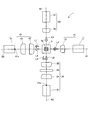
- FIG. 1 is a schematic configuration diagram of a water quality analyzer according to the first embodiment.
- the water quality analyzer 1 includes an excitation light irradiation optical system 10, a fluorescence detection optical system 20, a scattered light irradiation optical system 30, and a scattered light detection optical system 40 in four directions around the sample cell 5.
- the excitation light irradiation optical system 10 and the scattered light detection optical system 40 are arranged to face each other with the sample cell 5 interposed therebetween, and the scattered light irradiation optical system 30 and the fluorescence detection optical system 20 face each other with the sample cell 5 interposed therebetween. Are arranged.
- the optical axis A1 of the excitation light irradiation optical system 10 and the optical axis A2 of the fluorescence detection optical system 20 intersect perpendicularly, and the optical axis B1 of the scattered light irradiation optical system 30 and The optical axis B2 of the scattered light detection optical system 40 is arranged so as to intersect perpendicularly.
- the excitation light irradiation optical system 10 includes a light source 11 for excitation, and a collimator lens 12 disposed between the light source 11 and the sample cell 5.
- the fluorescence detection optical system 20 includes a fluorescence detector 21, a condenser lens 22, an optical filter 23, and a condenser lens 24 disposed between the fluorescence detector 21 and the sample cell 5.
- the condenser lenses 22 and 24 are arranged symmetrically with the convex surface facing the optical filter 23.
- the scattered light irradiation optical system 30 includes a light source 31 for detecting scattered light, and a collimating lens 32 disposed between the light source 31 and the sample cell 5.
- the scattered light detection optical system 40 includes a scattered light detector 41, and condensing lenses 42 and 43 disposed between the scattered light detector 41 and the sample cell 5.
- the condensing lenses 42 and 43 are arranged with their convex surfaces facing outward.
- the sample cell 5 is formed in a rectangular tube shape having a sample water channel 5a in the center, and extends in a direction perpendicular to the optical axes A1, A2, B1 and B2. Sample water to be measured is passed through the sample water channel 5a.
- a flow cell made of a transparent member such as quartz glass is used, but a square cell made of quartz glass can also be used.
- a light emitting diode, a laser diode, etc. which emit the light of a specific wavelength can be used.
- a photodiode, a photomultiplier tube, or the like can be used.
- the optical filter 23 is not particularly limited, and an optical element having a function of transmitting only light in a specific wavelength range and cutting other light and having a cut rate smaller than 100% is used.
- the light source 11 for excitation and the light source 31 for detecting scattered light are turned on.
- the actual sample is passed through the sample water channel 5 a of the sample cell 5.
- the excitation light source 11 emits excitation light source light L 1, and the light source light L 1 passes through the collimator lens 12 to become near-parallel light (collimated light) and is irradiated onto the sample water in the sample cell 5.
- the detection target component in the sample water is excited by the light source light L1 and emits fluorescence L2.
- the fluorescence L2 is collected by the condenser lens 22, reaches the optical filter 23, and after light of a specific wavelength is extracted by the optical filter 23, it is condensed by the condenser lens 24, and is received by the light receiving surface of the fluorescence detector 21. 21a is reached.
- a part of the light source light L1 travels straight through the sample cell 5, passes through the sample cell 5, and is collected by the condensing lenses 42 and 43 as transmitted light L 1 ′ and reaches the light receiving surface 41 a of the scattered light detector 41.
- a scattered light detection light source light L3 is emitted from the scattered light detection light source 31, and the light source light L3 passes through the collimator lens 32 to become near-parallel light and is irradiated onto the sample water in the sample cell 5.
- the light source light L3 is scattered by a fine particle component as a suspended substance in the sample water, and scattered light L4 is emitted.
- the scattered light L4 is collected by the condenser lenses 42 and 43 and reaches the light receiving surface 41a of the scattered light detector 41.
- a part of the light source light L3 travels straight through the sample cell 5, passes through the sample cell 5, is condensed by the condensing lens 22 as transmitted light L3 ′, and reaches the optical filter 23.
- most of the transmitted light L3 ′ is cut by the optical filter 23, a part of the transmitted light L3 ′ is transmitted and condensed on the condenser lens 24, and reaches the light receiving surface 21a of the fluorescence detector 21.
- the excitation light source 11 when monitoring the light amount of the excitation light source 11, the excitation light source 11 is turned on and the scattered light detection light source 31 is turned off.
- water pure water
- the light source light L1 emitted from the light source 11 passes through the collimator lens 12 and is irradiated to the sample cell 5.
- the light source light L1 passes through the sample cell 5 and is collected as transmitted light L1 ′ by the condenser lenses 42 and 43, reaches the light receiving surface 41a of the scattered light detector 41, and the transmitted light L1 ′ is detected.
- the excitation light source 11 When monitoring the light amount of the light source 31 for the scattered light detection 30, the excitation light source 11 is turned off and the scattered light detection light source 31 is turned on. Pure water is passed through the sample water channel 5 a of the sample cell 5.
- the light source light L3 emitted from the light source 31 passes through the collimating lens 32 and is irradiated to the sample cell 5.
- the light source light L3 passes through the sample cell 5, is condensed by the condenser lens 22 as transmitted light L3 ', and reaches the optical filter 23.
- a part of the transmitted light L3 ′ is condensed on the condenser lens 24 by the optical filter 23, reaches the light receiving surface 21a of the fluorescence detector 21, and the transmitted light L3 ′ is detected.
- the excitation light source 11 irradiates the sample cell 5 with the excitation light source light L1, and the fluorescence of a specific component in the sample water excited by the irradiation of the light source light L1.
- the fluorescence intensity is measured by detecting L2 with the fluorescence detector 21.
- the light source 31 for detecting scattered light is irradiated with the light source light L3 for detecting scattered light from the light source 31 for detecting scattered light, and the scattered light L4 scattered by the fine particles in the sample water by the irradiation of the light source light L3 is detected by the scattered light detector 41.
- Turbidity is measured by detecting. Since the fluorescence is detected while detecting the scattered light, the fluorescence intensity can be accurately measured while taking into account the influence of turbidity.
- the optical systems 10, 20, 30, 40 are the center of the sample water flow path 5 a of the sample cell 5, and the optical axis A 1 of the excitation light irradiation optical system 10 and the optical axis A 2 of the fluorescence detection optical system 20 are orthogonal to each other.
- the optical axis B1 of the irradiation optical system 30 and the optical axis B2 of the scattered light detection optical system 40 are arranged so as to be orthogonal to each other. For this reason, the fluorescence L2 emitted from the specific component in the sample water can be detected by the fluorescence detector 21 while suppressing the introduction of the transmitted light L1 ′ into the fluorescence detector 21. Further, the scattered light L4 emitted from the fine particles in the sample water can be detected by the scattered light detector 41 while suppressing the introduction of the transmitted light L3 ′ into the scattered light detector 41.
- the scattered light detector 41 transmits the transmitted light L1 ′ obtained by transmitting the light source light L1 through the sample cell 5. Can be detected. Since the light source 31 for detecting scattered light and the fluorescence detector 21 are arranged to face each other, the fluorescence detector 21 can detect the transmitted light L3 ′ transmitted through the sample cell 5 by the light source light L3.
- the excitation light source light L ⁇ b> 1 is irradiated from the excitation light source 11 to the sample cell 5, and the transmitted light L ⁇ b> 1 ′ transmitted through the sample cell 5 is detected by the scattered light detector 41.
- the light quantity of the light source 11 for excitation can be monitored.
- the sample cell 5 is irradiated with the light source light L3 for detecting scattered light from the light source 31 for detecting scattered light, and the transmitted light L3 ′ transmitted through the sample cell 5 is detected as a fluorescence detector.
- the transmitted light L3 ′ transmitted through the sample cell 5 is detected as a fluorescence detector.
- the fluorescence detector 21 of the fluorescence detection optical system 20 receives not only the fluorescence L2 emitted by the specific component in the sample water excited by the light source light L1 of the light source 11 but also the light source light L3.
- the transmitted light L3 ′ that has passed through the water is incident.
- the scattered light detector 41 of the scattered light detection optical system 40 not only the scattered light L4 scattered by the fine particles in the sample water due to the irradiation of the light source light L3 of the light source 31, but also the light source light L1 passes through the sample water.
- the transmitted light L1 ′ is incident.
- the optical axis B1 of the scattered light irradiation optical system 30 and the fluorescence detection optical system in the sample cell 5 The optical axis A2 of 20 may coincide with the optical axis A1 of the excitation light irradiation optical system 10 and the optical axis B2 of the scattered light optical system 40.
- the fluorescence 21 and the transmitted light L3 ′ are incident on the fluorescence detector 21, if the intensity of the transmitted light L3 ′ is significantly larger than the intensity of the fluorescence L2, the fluorescence is detected.
- the detection accuracy of the fluorescence L2 in the detector 21 is lowered.
- the scattered light L4 and the transmitted light L1 ′ are incident on the scattered light detector 41, if the intensity of the transmitted light L1 ′ is significantly larger than the intensity of the scattered light L4, the scattered light in the scattered light detector 41 is scattered. There is a possibility that the detection accuracy of the light L4 is lowered.
- the intersection of the optical axis A1 of the excitation light irradiation optical system 10 and the optical axis A2 of the fluorescence detection optical system 20 and the optical axis of the scattered light irradiation optical system 30 The amount of transmitted light L3 ′ and L1 ′ introduced into the detectors 21 and 41 is controlled by adjusting the distance between B1 and the optical axis B2 of the scattered light detection optical system 40.
- FIG. 2 is an explanatory diagram of a method for adjusting the amount of transmitted light introduced into each detector according to the above embodiment.
- the intersection P2 with the optical axis B2 is configured to be separated from the sample cell 5 by a distance D.
- the plane formed by the optical axis A1 of the excitation light irradiation optical system 10 and the optical axis A2 of the fluorescence detection optical system 20, and the optical axis B1 of the scattered light irradiation optical system 30 and the scattered light detection are detected.
- a plane formed by the optical axis B2 of the optical system 40 is separated by a distance D.
- the light L1 ′ is introduced at a position away from the optical axis B2 on the light receiving surface 41a of the scattered light detector 41.
- the intersection point P2 is positioned above the intersection point P1, but the intersection point P2 may be positioned below the intersection point P1.
- the distance D is preferably greater than 0 mm and not greater than 10 mm.
- the transmitted light L3 ′ and the optical axis A2 are prevented from matching, and the influence of the light amount of the transmitted light L3 ′ detected by the fluorescence detector 21 when measuring the sample water can be suppressed.
- the transmitted light L1 ′ is prevented from reaching the scattered light detector 41 or being too small to be difficult to detect even if it reaches the light, and the transmitted light L1 ′ is detected during light amount monitoring.
- the light quantity of the light source 11 can be monitored. Further, it is possible to prevent the transmitted light L3 ′ from reaching the fluorescence detector 21 or to be too small even if it reaches the fluorescence detector 21, and to detect the transmitted light L3 ′ and monitor the light amount of the light source 31 during light amount monitoring. Can do.
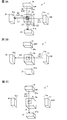
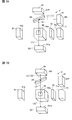
- FIG. 3 is an explanatory diagram of the measurement operation of the water quality analyzer according to the above embodiment.
- FIG. 3A is an explanatory diagram of the measurement operation of the fluorescence intensity and turbidity of the sample water according to the above embodiment.
- FIG. 3B is an explanatory diagram of the light amount detection operation of the excitation light irradiation optical system according to the above embodiment.
- FIG. 3C is an explanatory diagram of the light amount detection operation of the scattered light irradiation optical system according to the embodiment.
- Table 1 describes four measurement modes: normal measurement, light quantity monitoring reference, fluorescence light source light quantity detection, and scattered light source light quantity detection.
- the normal measurement mode shown in Table 1 is selected, and the fluorescence intensity and turbidity are measured.
- the actual sample is passed through the sample water channel 5 a of the sample cell 5.
- Both the excitation light source 11 and the scattered light detection light source 31 are turned on.
- the excitation light source 11 emits excitation light source light L1 and irradiates the sample water in the sample cell 5.
- the detection target component in the sample water is excited by the light source light L ⁇ b> 1 to emit fluorescence L ⁇ b> 2, and the fluorescence L ⁇ b> 2 reaches the light receiving surface 21 a of the fluorescence detector 21.
- Part of the light source light L1 travels straight through the sample cell 5, passes through the sample cell 5, and reaches the light receiving surface 41a of the scattered light detector 41 as transmitted light L1 ′.
- Scattered light detection light source 31 emits scattered light detection light source light L3 and irradiates the sample water in the sample cell 5.
- the light source light L3 is scattered by the fine particle component in the sample water, and the scattered light L4 reaches the light receiving surface 41a of the scattered light detector 41.
- a part of the light source light L3 travels straight through the sample cell 5, passes through the sample cell 5, and reaches the light receiving surface 21a of the fluorescence detector 21 as transmitted light L3 ′.
- the fluorescence L2 and transmitted light L3 ′ of the actual sample are detected on the light receiving surface 21a of the fluorescence detector 21, and the scattered light L4 of the actual sample is detected on the light receiving surface 41a of the scattered light detector 41.
- the transmitted light L1 ′ is detected.
- the light beam L3 transmitted through the sample cell 5 is separated by separating the optical axis B1 of the scattered light irradiation optical system 30 and the optical axis A2 of the fluorescence detection optical system 20 by a distance D.
- L3 ′ is introduced at a position away from the optical axis A2 on the light receiving surface 21a of the fluorescence detector 21.
- the transmitted light L1 ′ transmitted through the sample cell 5 by the light source light L1 is The light is introduced into the light receiving surface 41a of the scattered light detector 41 at a position away from the optical axis B2.
- the light quantity of the transmitted light L3 ′ introduced into the fluorescence detection optical system 20 can be adjusted, the influence of the transmitted light L3 ′ detected by the fluorescence detector 21 is suppressed, and the fluorescence L2 is accurately detected in the fluorescence detector 21. It can be detected well. Further, since the amount of transmitted light L1 ′ introduced into the scattered light detection optical system 40 can be adjusted, the influence of the amount of transmitted light L1 ′ detected by the scattered light detector 41 is suppressed, and the scattered light detector 41 Thus, the scattered light L4 can be detected with high accuracy.
- the reference mode for monitoring the light quantity is selected during the background measurement, and the background light quantity during the light quantity monitoring of the light sources 11 and 31 is detected.
- Water pure water that does not contain a fluorescent component and a scattered light component is passed through the sample cell 5.
- Both the excitation light source 11 and the scattered light detection light source 31 are OFF, and the background light quantity is detected by the fluorescence detector 21 and the scattered light detector 41. In general, since the detectors 21 and 41 are shielded from the outside, the amount of light in the background is almost zero.
- the light quantity detection mode of the excitation light source is selected, and the transmitted light L1 'of the light source 11 is detected.
- Pure water is passed through the sample water channel 5 a of the sample cell 5.
- the excitation light source 11 is turned on and the scattered light detection light source 31 is turned off.
- the light source light L1 emitted from the light source 11 is applied to the sample cell 5.
- the light source light L1 passes through the sample cell 5, reaches the light receiving surface 41a of the scattered light detector 41 as transmitted light L1 ′, and the transmitted light L1 ′ is detected. Since the scattered light detection optical system 40 (see FIG. 1) is disposed facing the excitation light irradiation optical system 10 (see FIG. 1), the transmitted light L1 ′ can be detected, and a dedicated light amount detector is provided.
- the light quantity of the light source 11 can be monitored without providing it.
- the light amount detection mode of the scattered light detection light source is selected, and the transmitted light L3 ′ of the light source 31 is detected.
- Pure water is passed through the sample water channel 5 a of the sample cell 5.
- the excitation light source 11 is turned off and the scattered light detection light source 31 is turned on.
- the light source light L3 emitted from the light source 31 is applied to the sample cell 5.
- the light source light L3 passes through the sample cell 5, reaches the light receiving surface 21a of the fluorescence detector 21 as transmitted light L3 ', and the transmitted light L3' is detected. Since the fluorescence detection optical system 20 (see FIG. 1) is disposed opposite to the scattered light irradiation optical system 30 (see FIG. 1), the transmitted light L3 ′ can be detected, and a dedicated light amount detector is provided. Therefore, the light amount of the light source 31 can be monitored.
- the water quality analyzer 1 includes the intersection P1 between the optical axis A1 of the excitation light irradiation optical system 10 and the optical axis A2 of the fluorescence detection optical system 20, and the scattered light irradiation optical system.
- the distance D is adjusted by separating the intersection P2 of the optical axis B1 of 30 and the optical axis B2 of the scattered light detection optical system 40 in the sample cell 5.
- the fluorescence detector 21 can accurately detect the fluorescence L2 while suppressing the influence of the transmitted light L3 ′, and the scattered light detector 41 suppresses the influence of the transmitted light L1 ′.
- the scattered light L4 can be detected with high accuracy.
- the scattered light detector 41 can detect the light amount of the transmitted light L1 ′, so that the scattered light detection optical system 40 does not provide a dedicated light amount detector.
- the amount of light of the light source 11 can be monitored.
- the light amount of the transmitted light L3 ′ can be detected by the fluorescence detector 21, so that the scattered light detection is performed in the fluorescence detection optical system 20 without providing a dedicated light amount detector.
- the amount of light of the light source 31 can be monitored. Accordingly, stable water quality analysis can be performed in consideration of a decrease in the light amount of the excitation light source 11 and the scattered light detection light source 31.
- the water quality analyzer irradiates a specific component in the sample water with excitation light for water in water and sewage systems, environmental water such as seawater, river water, lake water, etc., and sample water such as drainage.
- the emitted fluorescence is detected and a specific component is measured.
- the fluorescence intensity of specific components varies due to excitation light being affected by scattering, absorption, etc. by the suspended materials.
- the wavelength band is different between excitation light and scattered light detection light used for turbidity measurement. Since the light absorption characteristics in these two different wavelength bands differ depending on the sample water, the fluorescence of a specific component of the sample water may not be accurately measured only by correcting the fluorescence intensity by turbidity. That is, even if the suspended matter concentration in the sample water is the same, if the type of suspended matter is different, the absorption characteristics of the excitation light and fluorescence in the suspended matter will be different. Cannot be corrected.
- fluorescence emitted from specific components of the sample water also decreases due to absorption of the sample water.
- the wavelength of fluorescence is generally different from the wavelength of excitation light and irradiation light for turbidity measurement.
- the water quality analyzer has a fluorescence detection function and a turbidity detection function, and a transmitted light detecting optical system for transmitting transmitted light and turbidity through which excitation light has passed through the sample water.
- the transmitted light transmitted through the sample water is detected.
- Absorption characteristic at the wavelength of the excitation light is detected from the transmitted light transmitted through the sample water, and the absorption characteristic at the wavelength of the irradiated light for turbidity measurement is detected from the transmitted light transmitted through the sample water. This is used to predict the absorption characteristic at the wavelength of the fluorescence and correct the fluorescence intensity.
- the fluorescence emitted from the specific component in the sample water can be accurately measured without increasing the wavelength of light to be irradiated or detected.
- transmitted light in which the excitation light source light is transmitted through the sample cell and transmitted light in which the scattered light detection light source light is transmitted through the sample cell are detected by the transmitted light detection optical system.
- the absorbance at the wavelength of the light source light for exciting the sample water and the absorbance at the wavelength of the light source light for detecting scattered light are calculated from the transmitted light intensity, and the absorbance at the fluorescence wavelength is predicted from these absorbances. .
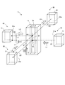
- FIG. 4 is a schematic configuration diagram of a water quality analyzer according to the second embodiment.
- FIG. 5 is a block diagram showing the configuration of the control unit according to the above embodiment.
- the water quality analyzer 2 includes a transmitted light detection optical system 100, a fluorescence detection optical system 70, a scattered light irradiation optical system 80 for detecting turbidity, and a scattered light detection optical system 90 in four directions around the sample cell 50. Yes.
- the fluorescence detection optical system 70 and the scattered light detection optical system 90 are arranged to face each other with the sample cell 50 interposed therebetween, and the scattered light irradiation optical system 80 and the transmitted light detection optical system 100 face each other with the sample cell 50 interposed therebetween. Are arranged.
- a half mirror (optical member) 55 is provided between the scattered light irradiation optical system 80 and the sample cell 50, and an excitation light irradiation optical system 60 is disposed on the side of the optical member 55. .
- the optical member 55 is disposed at a position for guiding the excitation light source light L1 and the scattered light detection light source light L3 described later to the sample cell 50.
- the optical member 55 and the transmitted light detection optical system 100 are opposed to each other with the sample cell 50 interposed therebetween.
- the excitation light irradiation optical system 60 has a light source 61 for excitation, and a collimator lens 62 disposed between the light source 61 and the optical member 55.
- the fluorescence detection optical system 70 includes a fluorescence detector 71, a condenser lens 72, an optical filter 73, and a condenser lens 74 disposed between the fluorescence detector 71 and the sample cell 50.
- the condenser lenses 72 and 74 are arranged symmetrically with the optical filter 73.
- the scattered light irradiation optical system 80 includes a light source 81 for detecting scattered light, and a collimator lens 82 disposed between the light source 81 and the optical member 55.
- the scattered light detection optical system 90 includes a scattered light detector 91 and condenser lenses 92 and 93 disposed between the scattered light detector 91 and the sample cell 50.
- the transmitted light detection optical system 100 includes a transmitted light detector 101 and a condensing lens 102 disposed between the sample cell 50.
- the light source 61 for excitation a light emitting diode, a laser diode, or the like that can emit light having a wavelength ⁇ 1 can be used.
- the light source 81 for detecting scattered light a light emitting diode, a laser diode, or the like that can emit light having a wavelength ⁇ 2 can be used.
- the wavelength ⁇ 1 of the excitation light source light L1 is preferably 250 nm or more and 350 nm or less
- the wavelength ⁇ 2 of the scattered light detection light source light L3 is preferably 600 nm or more and 900 nm or less.
- the scattered light detector 91 a silicon photodiode or the like that includes light having a wavelength ⁇ 2 of the light source light L3 for detecting scattered light in the detection range can be used.
- the fluorescence detector 71 a photomultiplier tube or the like can be used, whereby a minute fluorescence having a specific wavelength ⁇ 3 of the fluorescence selectively transmitted through the optical filter 73 can be detected.
- the optical filter 73 is not particularly limited, and a band pass filter or the like that selectively transmits only the fluorescence having the wavelength ⁇ 3 emitted by the target component to be detected can be used, thereby cutting light other than the wavelength ⁇ 3. Is done.
- the specific wavelength ⁇ 3 it is preferable to select the peak wavelength of fluorescence from the viewpoint of increasing the detection efficiency by the fluorescence detector 71.
- the wavelength ⁇ 3 is preferably not less than the wavelength ⁇ 1 and not more than the wavelength ⁇ 2.
- the light absorbency in wavelength (lambda) 3 can be accurately estimated in the estimation part mentioned later.
- the transmitted light detector 101 a silicon photodiode or the like that includes light of the wavelength ⁇ 1 of the excitation light source light L1 and light of the wavelength ⁇ 2 of the scattered light detection light source L3 in the detection range can be used.
- the optical member 55 a half mirror, a beam splitter, etc. can be used.
- the light source 61 for excitation and the light source 81 for detecting scattered light are alternately turned on.
- the actual sample is passed through the sample water channel 50a of the sample cell 50.
- the excitation light source 61 emits excitation light source light L1 having a wavelength ⁇ 1.
- the light source light L1 passes through the collimator lens 62 to become near-parallel light (collimated light), is reflected by the optical member 55, and is reflected by the sample cell 50.
- the sample water is irradiated.
- the detection target component in the sample water is excited by the light source light L1 and emits fluorescence L2.
- the fluorescence L2 is collected by the condenser lens 72, reaches the optical filter 73, and after the light L2 ′ having the specific wavelength ⁇ 3 is extracted by the optical filter 73, it is condensed by the condenser lens 74 and is detected by the fluorescence detector 71. Reaches the light receiving surface 71a. A part of the light source light L1 travels straight through the sample cell 50, passes through the sample cell 50, is collected by the condenser lens 102 as transmitted light L1 ′, and reaches the light receiving surface 101a of the transmitted light detector 101.
- the scattered light detection light source 81 emits scattered light detection light source light L3 having a wavelength ⁇ 2.
- the light source light L3 passes through the collimating lens 82 and becomes near-parallel light, passes through the optical member 55, and passes through the sample cell 50.
- the sample water is irradiated.
- the light source light L3 is scattered by a fine particle component as a suspended substance in the sample water, and scattered light L4 is emitted.
- the scattered light L4 is collected by the condenser lenses 92 and 93 and reaches the light receiving surface 91a of the scattered light detector 91. Further, a part of the light source light L3 travels straight through the sample cell 50, passes through the sample cell 50, is collected by the condenser lens 102 as transmitted light L3 ′, and reaches the light receiving surface 101a of the transmitted light detector 101.
- the excitation light source 61 irradiates the sample cell 50 with the excitation light source light L1 having the wavelength ⁇ 1, and the excitation in the sample water is excited by the irradiation of the light source light L1.
- the fluorescence intensity is measured by detecting the fluorescence L2 of wavelength ⁇ 3 emitted by the component with the fluorescence detector 71.
- the sample cell 50 is irradiated with the light source light L3 for detecting scattered light having the wavelength ⁇ 2 from the light source 81 for detecting scattered light, and the scattered light L4 scattered by the fine particles in the sample water is detected by the irradiation of the light source light L3.
- the turbidity is measured by detecting with the instrument 91. Since fluorescence is detected while detecting scattered light, the fluorescence intensity of a specific component to be detected in the sample water can be measured in consideration of the influence of turbidity.
- the traveling direction light of the excitation light source light L1 reflected by the optical member 55 and the optical axis C1 of the fluorescence detection optical system 70 are orthogonal to each other. For this reason, it is possible to detect the fluorescence L2 ′ emitted from a specific component in the sample water with the fluorescence detector 71 while suppressing the introduction of the transmitted light L1 ′ to the fluorescence detector 71.
- the optical axis D1 of the scattered light irradiation optical system 80 and the optical axis D2 of the scattered light detection optical system 90 are orthogonal to each other. Therefore, the scattered light L4 emitted from the fine particles in the sample water can be detected by the scattered light detector 91 while suppressing the transmission light L3 ′ from being introduced into the scattered light detector 91.
- the transmitted light detection optical system 100 faces the optical member 55 with the sample cell 50 interposed therebetween, and the excitation light source light L1 and the scattered light detection light source light L3 are supplied to the sample cell 50. It is arranged to lead to. Therefore, at the time of measuring the sample water, the excitation light source light L1 with the wavelength ⁇ 1 emitted from the excitation light source 61 is reflected by the optical member 55 and introduced into the sample cell 50, and the transmitted light L1 ′ transmitted through the sample cell 50 is transmitted. Can be detected by the transmitted light detector 101.
- the scattered light detection light source light L3 of wavelength ⁇ 2 emitted from the scattered light detection light source 81 passes through the optical member 55 and is introduced into the sample cell 50, and the transmitted light L3 ′ transmitted through the sample cell 50 is transmitted. It can be detected by the fluorescence detector 71.
- the prediction unit 121 (see FIG. 5) described later allows the sample cell 50 to pass the actual sample and pure water. The absorbance of the actual sample can be obtained by calculating the ratio of transmitted light intensity in each case.
- the water quality analyzer 2 is provided with a control unit 120 that performs overall control of each unit.
- the controller 120 repeatedly turns on and off the light source 61 for excitation and the light source 81 for scattered light detection by switching between a fluorescence detection mode and a turbidity detection mode, which will be described later.
- the control unit 120 includes a processor that executes various processes, a memory, and the like.
- the memory is composed of one or a plurality of storage media such as ROM (Read Only Memory) and RAM (Random Access Memory) depending on the application.
- the control unit 120 includes a prediction unit 121, a turbidity correction unit 122, and an absorbance correction unit 123. Note that the control unit 120 may include a control circuit, a controller, a control device, and the like.
- the absorbance of the sample water in the excitation light source light L1 having the wavelength ⁇ 1 is calculated from the transmitted light L1 ′ detected by the transmitted light detector 101, and the scattered light having the wavelength ⁇ 2 is detected from the transmitted light L3 ′.
- the absorbance of the sample water in the light source light L3 is calculated.
- the absorbance of the sample water in the fluorescence of the wavelength ⁇ 3 is predicted from the absorbance of the sample water at the wavelengths ⁇ 1 and ⁇ 2.
- the prediction unit 121 may include a prediction circuit, a predictor, a prediction device, and the like.
- the turbidity correction unit 122 corrects the fluorescence intensity of the sample water detected by the fluorescence detector 71 using the turbidity measured from the scattered light L4 having the wavelength ⁇ 2 detected by the scattered light detector 91. To correct the turbidity of the fluorescence intensity.
- the turbidity correction unit 122 may include a turbidity correction circuit, a turbidity corrector, a turbidity correction device, and the like.
- the absorbance correction unit 123 corrects the fluorescence intensity corrected by the turbidity correction unit 122 using the absorbance of the sample water at the wavelength ⁇ 1 calculated by the prediction unit 121 and the absorbance at the predicted wavelength ⁇ 3. Thus, the fluorescence intensity corrected for absorbance is calculated.
- the absorbance correction unit 123 may include an absorbance correction circuit, an absorbance corrector, an absorbance correction device, and the like.
- the water quality analyzer 2 predicts the absorbance at the wavelength ⁇ 3 from the absorbance of the sample water at the wavelengths ⁇ 1 and ⁇ 2. Accordingly, it is not necessary to install a light source or the like that emits light of wavelength ⁇ 3, measure the absorbance of sample water at wavelength ⁇ 3, and correct the fluorescence intensity using the measured value. It can be.
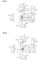
- FIG. 6 is an explanatory diagram of the measurement operation of the water quality analyzer in the normal measurement mode according to the above embodiment.
- FIG. 6A is an explanatory diagram of the measurement operation of the fluorescence intensity of the actual sample and the transmitted light of the excitation light source light according to the above embodiment.
- FIG. 6B is an explanatory diagram of the measurement operation of the scattered light intensity of the real sample and the transmitted light of the light source light for detecting the scattered light according to the embodiment.
- FIG. 7 is an explanatory diagram of the measurement operation of the water quality analyzer in the pure water measurement mode according to the above embodiment.
- FIG. 7A is an explanatory diagram of the measurement operation of the transmitted light of the light source light for the excitation light of pure water according to the above embodiment.
- FIG. 7B is an explanatory diagram of the measurement operation of the transmitted light of the light source light for detecting the scattered light of pure water according to the above embodiment.
- FIG. 8 is a diagram illustrating an example of the absorbance measurement of sample water containing a suspended substance. In FIG. 8, the horizontal axis represents wavelength and the vertical axis represents absorbance.
- the normal measurement mode shown in Table 2 is selected, and the actual sample is passed through the sample water flow path 50 a of the sample cell 50.
- FIG. 6A when measuring the fluorescence L2 ′ intensity of the specific component to be detected in the actual sample and the transmitted light L1 S ′ transmitted through the sample cell 50 by the excitation light source light L1, normal measurement is performed.
- the fluorescence detection mode in the mode is selected, and the intensity of the fluorescence L2 and the intensity of the transmitted light L1 S 'are measured.
- the excitation light source 61 is turned on, and the scattered light detection light source 81 is turned off.
- the excitation light source 61 emits excitation light source light L 1 having a wavelength ⁇ 1, is reflected by the optical member 55, and is applied to the actual sample of the sample cell 50.
- the detection target component in the actual sample is excited by the light source light L1 to emit fluorescence L2 having a peak on the longer wavelength side than the wavelength ⁇ 1 of the excitation light source light L1, and the fluorescence L2 is emitted by the optical filter 73 at a specific wavelength ⁇ 3.
- the light L2 ′ After the light L2 ′ is extracted, the light reaches the light receiving surface 71a of the fluorescence detector 71.
- a part of the light source light L1 travels straight through the sample cell 50, passes through the sample cell 50, and reaches the light receiving surface 101a of the transmitted light detector 101 as transmitted light L1 S ′.
- the turbidity in the normal measurement mode of Table 2 is measured.
- the degree detection mode is selected, and the intensity of the scattered light L4 and the intensity of the transmitted light L3 S ′ are measured.
- the excitation light source 61 is turned off, and the scattered light detection light source 81 is turned on.
- a scattered light detection light source light L3 having a wavelength ⁇ 2 is emitted from the scattered light detection light source 81, passes through the optical member 55, and is irradiated onto the actual sample of the sample cell 50.
- the light source light L3 is scattered by the fine particle component in the actual sample, and the scattered light L4 reaches the light receiving surface 91a of the scattered light detector 91. Part of the light source light L3 travels straight through the sample cell 50, passes through the sample cell 50, and reaches the light receiving surface 101a of the transmitted light detector 101 as transmitted light L3 S '.
- the fluorescence detector 71 detects the fluorescence component L2 ′ of the actual sample having the wavelength ⁇ 3, and the transmitted light detector 101 detects the transmitted light L1 S ′.
- the scattered light detector 91 detects the scattered light L4 of the actual sample, and the transmitted light detector 101 detects the transmitted light L3 S ′.
- the control unit 120 see FIG.
- the pure water measurement mode shown in Table 2 when measuring pure water, the pure water measurement mode shown in Table 2 is selected, and pure water is passed through the sample water flow path 50 a of the sample cell 50.
- the excitation light source light L1 measures the transmitted light L1 0 ′ transmitted through the pure water of the sample cell 50
- the fluorescence detection mode in the pure water measurement mode is selected, and the transmitted light detection is performed.
- the intensity of the transmitted light L1 0 ′ is detected by the device 101.
- the excitation light source 61 is turned on, and the scattered light detection light source 81 is turned off.
- the light source light L1 having the wavelength ⁇ 1 emitted from the excitation light source 61 is reflected by the optical member 55 and irradiated onto the pure water of the sample cell 50.
- Source light L1 is transmitted through the sample cell 5, 'reaches the light receiving surface 101a of the transmitted light detector 101, the transmitted light L1 0 as' is detected transmitted light L1 0.
- the turbidity detection mode in the pure water measurement mode is selected and transmitted.
- the intensity of the transmitted light L3 0 ′ is detected by the photodetector 101.
- the excitation light source 61 is turned off, and the scattered light detection light source 81 is turned on.
- the light source light L3 having the wavelength ⁇ 2 emitted from the light source 81 for detecting scattered light passes through the optical member 55 and is irradiated on the pure water of the sample cell 50.
- Source light L3 is transmitted through a sample cell 50 'reaches the light receiving surface 101a of the transmitted light detector 101, the transmitted light L3 0 as' is detected transmitted light L3 0.
- the absorbance indicating the absorbance of the sample water is calculated.
- the absorbance A ⁇ 1 of the actual sample in the excitation light source light L1 having the wavelength ⁇ 1 is calculated.
- the absorbance A ⁇ 2 of the actual sample in the light L3 is calculated.
- the pure water measurement mode is selected by the control unit 120 (see FIG. 5), and the transmitted light L1 0 ′ of the excitation light source light L1 and the transmitted light source light L3 for detecting scattered light in pure water are transmitted.
- the light L3 0 ′ is measured in advance or periodically.
- the types of suspended substances and the absorption characteristics of sample water will be described. Even if the concentration of the suspended substance in the sample water, that is, the turbidity is the same, the absorption characteristics of excitation light and fluorescence in the suspended substance differ depending on the type of suspended substance.
- the solid line indicates the absorption spectrum of the white suspension solution
- the broken line indicates the absorption spectrum of the black suspension solution.
- the turbidity measured by the scattered light measurement is the same, but the absorption spectra differ greatly because the types of the suspended substances are different.
- the absorbance of the sample water containing the white suspended substance tended to increase on the short wavelength side and decrease on the long wavelength side.
- the absorbance of the sample water containing the black suspended substance has a wide range of wavelengths that have the same magnitude from a short wavelength to a long wavelength. Note that, in light of a predetermined wavelength, the greater the absorbance, the greater the absorption of light by the sample water. Therefore, even if the sample water has the same concentration of the detection target component, the fluorescence intensity detected by the fluorescence detector 71 is Get smaller.
- the absolute value of the absorbance on the short wavelength side and the absorbance on the long wavelength side and the ratio thereof vary greatly depending on the type of suspended matter contained in the sample water. For this reason, from the absolute value of the absorbance on the short wavelength side and the absorbance on the long wavelength side and the ratio thereof, the absorbance at the specific wavelength, that is, the fluorescence wavelength can be predicted. A linear approximation method or the like can be used to predict the absorbance at a specific wavelength.
- the wavelength ⁇ 1 of the excitation light source light L1 is set to, for example, 250 nm or more and 350 nm or less on the short wavelength side in the ultraviolet region
- the fluorescence of organic substances and oil components that are detection target components in the actual sample is, for example, 350 nm to 500 nm as the peak wavelength. Appears near. That is, it is fluorescence of wavelength ⁇ 3 emitted by a specific component in the sample water.
- the wavelength ⁇ 2 of the scattered light detection light source light L3 used for turbidity measurement near infrared light is used from visible light having a wavelength of 600 nm to 900 nm on the long wavelength side, for example.
- the absorbance A ⁇ 1 of the actual sample in the excitation light source light L1 having the wavelength ⁇ 1 from the actually measured transmitted light L1 S ′ and L1 0 ′ and the wavelength from the actually measured transmitted light L3 S ′ and L3 0 ′.
- the absorbance A ⁇ 2 of the actual sample in the light source light L3 for detecting scattered light of ⁇ 2 is calculated.
- the prediction unit 121 an absorbance A .lambda.1 of short wavelength .lambda.1 side absolute value of the absorbance A .lambda.2 the long wavelength .lambda.2 side and its ratio to predict the absorbance A [lambda] 3 of the fluorescence at the wavelength [lambda] 3 between the wavelength .lambda.1 and the wavelength .lambda.2.
- the wavelength ⁇ 3 is preferably the peak wavelength of the fluorescence spectrum.
- the actually measured transmitted light L1 S ', L1 0' and L3 S ', L3 0' wavelengths .lambda.1 calculated from the absorbance A .lambda.1 real sample in .lambda.2, predicting absorbance A [lambda] 3 from A .lambda.2 at the wavelength [lambda] 3
- the fluorescence intensity of the detection target component can be accurately measured regardless of the type of suspended substance.
- the water quality analyzer 2 can have a simple configuration.
- the water quality analyzer 2 includes the transmitted light L1 ′ of the excitation light source light L1 having the first wavelength ⁇ 1 and the light source light L3 for detecting scattered light having the second wavelength ⁇ 2.
- the absorbances A ⁇ 1 and A ⁇ 2 of the sample water at the first wavelength ⁇ 1 and the second wavelength ⁇ 2 are calculated from the transmitted light L3 ′.
- absorbance A .lambda.1 predicts the absorbance A [lambda] 3 in fluorescence of the third wavelength [lambda] 3 by using the A .lambda.2, using the absorbance A [lambda] 3 in fluorescence of the third wavelength [lambda] 3 to the correction of the fluorescence intensity of the measurement target component.
- the fluorescence intensity can be accurately measured, and a light source that emits light of the third wavelength ⁇ 3 and a detector that detects the transmitted light of the light source light are provided in the water quality analyzer 2 to correct the fluorescence intensity. Since it is not necessary to measure the absorbance of the sample water at the third wavelength ⁇ 3, the water quality analyzer 2 can have a simple configuration.
- the present invention is not limited to the first and second embodiments, and can be implemented with various modifications.
- the size, shape, and the like illustrated in the accompanying drawings are not limited to this, and can be appropriately changed within a range in which the effect of the present invention is exhibited.
- various modifications can be made without departing from the scope of the object of the present invention.
- the arrangement of the optical systems 10, 20, 30, and 40 is such that the fluorescence detection optical system 20 can detect the light amount of the scattered light irradiation optical system 30 and the scattered light detection optics. If the system 40 is arrange
- the optical systems 10, 20, 30, and 40 are configured such that the fluorescence L2 and the transmitted light L3 ′ are introduced into the light receiving surface 21a of the fluorescence detector 21, and the scattered light L4 and the transmitted light are transmitted. If light L1 'is introduce
- the excitation light irradiation optical system 10 and the scattered light irradiation optical system 30 are configured to include the collimating lenses 12 and 32.
- the light sources 11 and 31 are preliminarily incorporated with lenses. If a light source capable of forming near-parallel light is used, the collimating lenses 12 and 32 may not be included.
- the sample cell 5 is formed in a rectangular tube shape.
- the fluorescence detector 21 detects the fluorescence L2 and the transmitted light L3 ′
- the scattered light detector 41 detects the fluorescence.
- the configuration is not limited to this configuration as long as the scattered light L4 and the transmitted light L1 ′ are detected.
- the arrangement of the optical systems 60, 70, 80, 90, 100 is such that the transmitted light detection optical system 100 can detect the light amount of the scattered light irradiation optical system 80 and is excited. If it arrange
- each optical system 60, 70, 80, 90, 100 is such that fluorescence L2 ′ is introduced into the light receiving surface 71a of the fluorescence detector 71, and scattered light L4 is detected by scattered light.
- fluorescence L2 ′ is introduced into the light receiving surface 71a of the fluorescence detector 71
- scattered light L4 is detected by scattered light.
- the excitation light irradiation optical system 60 and the scattered light irradiation optical system 80 are configured to include the collimating lenses 62 and 82, but lenses are incorporated in the light sources 61 and 81 in advance. If a light source capable of forming near-parallel light is used, the collimating lenses 62 and 82 may not be included.
- the sample cell 50 is formed in a rectangular tube shape.
- the fluorescence L2 ′ is detected by the fluorescence detector 71
- the scattered light L4 is detected by the scattered light detector 41.
- the configuration is not limited to this configuration as long as the transmitted light detector 101 detects the transmitted lights L1 ′ and L3 ′.
- the configuration in which the absorbance A ⁇ 3 at the wavelength ⁇ 3 is predicted from the measured absorbances A ⁇ 1 and A ⁇ 2 at the actually measured wavelengths ⁇ 1 and ⁇ 2 in the second embodiment, and the fluorescence intensity is corrected for the absorbance using this is described in the first embodiment. You may apply to.
- Absorbance A ⁇ 2 at ⁇ 2 is calculated.
- the absorbance A ⁇ 1 at the wavelength ⁇ 1 is calculated from the transmitted light L1 ′ of the excitation light source 11 having the wavelength ⁇ 1 detected by the scattered light detector 41.
- the absorbance A ⁇ 3 at the wavelength ⁇ 3 can be predicted.
- the water quality analyzer of the present invention includes an excitation light irradiation optical system for irradiating a sample water to be measured with excitation light source light, and fluorescence of a specific component in the sample water excited by irradiation of the excitation light source light.
- Fluorescence detection optical system for detecting, scattered light irradiation optical system for irradiating the sample water with light source light for detecting scattered light, and scattered light scattered by fine particles in the sample water by irradiation of the light source light for detecting scattered light
- a scattered light detecting optical system for detecting the light quantity of the excitation light irradiation optical system and the light quantity of the scattered light irradiation optical system.
- the fluorescence detection optical system can detect the light amount of the scattered light irradiation optical system, and the scattered light detection optical system can detect the light amount of the excitation light irradiation optical system. It is arranged to be.
- the fluorescence detection optical system when measuring the sample water, the fluorescence is detected by the fluorescence detection optical system while detecting the scattered light by the scattered light detection optical system. Strength can be measured with high accuracy.
- the scattered light detection optical system when monitoring the light amount of the excitation light source, the scattered light detection optical system can also detect the light amount of the excitation light source. Therefore, without providing a dedicated light amount detector, the scattered light detection optical system can be used for excitation. The light quantity of the light source can be monitored.
- the fluorescence detection optical system when monitoring the amount of light from the light source for scattered light detection, the fluorescence detection optical system can also detect the amount of light from the light source for scattered light detection, so it is possible to detect scattered light in the fluorescence detection optical system without providing a dedicated light amount detector. It is possible to monitor the amount of light of the light source for use. Accordingly, stable water quality analysis can be performed in consideration of a decrease in the light amount of the excitation light source and the scattered light detection light source.
- the excitation light irradiation optical system and the scattered light detection optical system are opposed to each other with a sample water passage container interposed therebetween, and the scattered light irradiation optical system and the fluorescence detection optical system are The sample water passage container is opposed to the other.
- the excitation light irradiation optical system and the scattered light detection optical system are opposed to each other, it is possible to detect the amount of transmitted light that has passed through the sample water flow container for the excitation light source light.
- the scattered light irradiation optical system and the fluorescence detection optical system are opposed to each other, it is possible to detect the amount of transmitted light that has passed through the sample water passage container of the light source light for detecting scattered light. Thereby, the light quantity monitoring of each light source can be performed.
- the optical axis of the excitation light irradiation optical system and the optical axis of the fluorescence detection optical system intersect perpendicularly at the center in the sample water flow container, and the scattered light irradiation optical system
- the optical axis of the system and the optical axis of the scattered light detection optical system intersect perpendicularly.
- the first intersection of the optical axis of the excitation light irradiation optical system and the optical axis of the fluorescence detection optical system, the optical axis of the scattered light irradiation optical system, and the scattered light detection optics The second intersection point with the optical axis of the system is separated in the sample water flow container.
- the accuracy of the detection function of the light source light for excitation can be maintained while suppressing the influence of the transmitted light that has passed through the water container. Since the optical axis of the excitation light irradiation optical system and the optical axis of the scattered light detection optical system are separated from each other, the scattered light detection optical system transmits the excitation light source light through the sample water flow container when measuring the sample. The accuracy of the light source light detection function for detecting scattered light can be maintained while suppressing the influence of transmitted light.
- the distance between the first intersection and the second intersection is greater than 0 mm and not more than 10 mm.
- the absorbance of the sample water at the first wavelength of the light source light for excitation is calculated from the first transmitted light through which the light source light for excitation has passed through the sample water, and the scattered light
- the absorbance of the sample water at the second wavelength of the scattered light detection light source light is calculated from the second transmitted light through which the detection light source light has passed through the sample water, and the first wavelength and the second wavelength are calculated.
- the absorbance at the third wavelength fluorescence is predicted using these absorbances, and the absorbance at the third wavelength fluorescence is used to correct the fluorescence intensity of the measurement target component.
- the fluorescence intensity can be measured with high accuracy, and a light source that emits light of the third wavelength for correcting the fluorescence intensity and a detector that detects the transmitted light of the light source light are provided in the water quality analyzer. Since it is not necessary to measure the absorbance of the sample water at the third wavelength, the water quality analyzer can have a simple configuration.
- the absorbance of the sample water at the third wavelength is predicted from the absolute value and the ratio of the absorbance of the sample water at the first wavelength and the second wavelength. With this configuration, the absorbance at the third wavelength can be accurately predicted according to the type of suspended matter contained in the sample water.
- the excitation light source light transmits the first transmitted light transmitted through the sample water and the scattered light detection light source light transmits the second transmitted light transmitted through the sample water.
- the light detection optical system calculates the absorbance of the sample water at the first wavelength of the excitation light source light from the first transmitted light, and calculates the scattered light detection light source light from the second transmitted light.
- a prediction unit that calculates the absorbance of the sample water at the second wavelength and predicts the absorbance of the sample water at the third wavelength of the fluorescence from the absorbance of the sample water at the first wavelength and the second wavelength.
- the absorbance of the sample water at the first wavelength and the second wavelength is calculated from the transmitted light of the first wavelength excitation light source light and the transmitted light of the second wavelength scattered light detection light source light.
- the absorbance at the third wavelength fluorescence is predicted using these absorbances, and the absorbance at the third wavelength fluorescence is used to correct the fluorescence intensity of the measurement target component.
- the fluorescence intensity can be measured with high accuracy, and a light source or the like that irradiates the light of the third wavelength is provided in the water quality analyzer to correct the fluorescence intensity, and the absorbance at the third wavelength of the sample water is measured. Since it is not necessary, the water quality analyzer can have a simple configuration.
- the absorbance of the sample water at the third wavelength is predicted from the absolute value and the ratio of the absorbance of the sample water at the first wavelength and the second wavelength. With this configuration, the absorbance at the third wavelength can be accurately predicted according to the type of fine particles in the sample water.
- the third wavelength is the peak wavelength of the fluorescence spectrum of the specific component in the sample water.
- the turbidity correction unit calculates the fluorescence intensity corrected for turbidity.
- the turbidity corrected fluorescence intensity using the absorbance of the sample water at the first wavelength and the absorbance of the sample water at the third wavelength predicted by the prediction unit is provided.
- the first wavelength is not less than 250 nm and not more than 350 nm
- the second wavelength is not less than 600 nm and not more than 900 nm
- the third wavelength is not less than the first wavelength. It is preferable that the second wavelength or less. With this configuration, it is possible to accurately predict the absorbance at the third wavelength between the absorbance at the first wavelength on the short wavelength side and the absorbance at the second wavelength on the long wavelength side.
- the water quality analyzer of the present invention includes an optical member disposed at a position for guiding the excitation light source light and the scattered light detection light source light to the sample water flow container, and the optical member and the transmitted light.
- a detection optical system is opposed to the sample water passage container.
Landscapes
- Health & Medical Sciences (AREA)
- Life Sciences & Earth Sciences (AREA)
- Chemical & Material Sciences (AREA)
- Physics & Mathematics (AREA)
- Pathology (AREA)
- Immunology (AREA)
- General Physics & Mathematics (AREA)
- Analytical Chemistry (AREA)
- Biochemistry (AREA)
- General Health & Medical Sciences (AREA)
- Food Science & Technology (AREA)
- Medicinal Chemistry (AREA)
- Engineering & Computer Science (AREA)
- Nuclear Medicine, Radiotherapy & Molecular Imaging (AREA)
- Investigating, Analyzing Materials By Fluorescence Or Luminescence (AREA)
- Spectroscopy & Molecular Physics (AREA)
- Investigating Or Analysing Materials By Optical Means (AREA)
- Analysing Materials By The Use Of Radiation (AREA)
- Sampling And Sample Adjustment (AREA)
Priority Applications (6)
| Application Number | Priority Date | Filing Date | Title |
|---|---|---|---|
| KR1020187011809A KR102444477B1 (ko) | 2016-05-19 | 2017-02-23 | 수질 분석계 |
| DK17798949.8T DK3355048T3 (da) | 2016-05-19 | 2017-02-23 | Vandkvalitetsanalysator |
| JP2018518096A JP6436266B2 (ja) | 2016-05-19 | 2017-02-23 | 水質分析計 |
| CN201780003869.3A CN108351304B (zh) | 2016-05-19 | 2017-02-23 | 水质分析仪 |
| EP17798949.8A EP3355048B1 (en) | 2016-05-19 | 2017-02-23 | Water quality analyzer |
| US15/968,409 US10302564B2 (en) | 2016-05-19 | 2018-05-01 | Water quality analyzer |
Applications Claiming Priority (2)
| Application Number | Priority Date | Filing Date | Title |
|---|---|---|---|
| JP2016-100435 | 2016-05-19 | ||
| JP2016100435 | 2016-05-19 |
Related Child Applications (1)
| Application Number | Title | Priority Date | Filing Date |
|---|---|---|---|
| US15/968,409 Continuation US10302564B2 (en) | 2016-05-19 | 2018-05-01 | Water quality analyzer |
Publications (1)
| Publication Number | Publication Date |
|---|---|
| WO2017199511A1 true WO2017199511A1 (ja) | 2017-11-23 |
Family
ID=60326246
Family Applications (1)
| Application Number | Title | Priority Date | Filing Date |
|---|---|---|---|
| PCT/JP2017/006951 WO2017199511A1 (ja) | 2016-05-19 | 2017-02-23 | 水質分析計 |
Country Status (7)
| Country | Link |
|---|---|
| US (1) | US10302564B2 (ko) |
| EP (1) | EP3355048B1 (ko) |
| JP (1) | JP6436266B2 (ko) |
| KR (1) | KR102444477B1 (ko) |
| CN (1) | CN108351304B (ko) |
| DK (1) | DK3355048T3 (ko) |
| WO (1) | WO2017199511A1 (ko) |
Cited By (6)
| Publication number | Priority date | Publication date | Assignee | Title |
|---|---|---|---|---|
| KR20200027251A (ko) * | 2018-09-04 | 2020-03-12 | 경북대학교 산학협력단 | 혈구 분석 장치, 이를 이용한 혈구 분석 방법 |
| JP2022516217A (ja) * | 2018-10-25 | 2022-02-25 | プレアー ソシエテ・アノニム | 液滴中の不純物を検出および/または測定するための方法および装置 |
| CN114324166A (zh) * | 2021-12-31 | 2022-04-12 | 中国科学院西安光学精密机械研究所 | 基于浊度校正的自清洁式精细谱水体参数测量装置与方法 |
| WO2023037528A1 (ja) * | 2021-09-10 | 2023-03-16 | 富士電機株式会社 | 水質分析装置 |
| WO2024062833A1 (ja) * | 2022-09-22 | 2024-03-28 | 株式会社堀場製作所 | 蛍光分析用セル、蛍光分析装置、蛍光分析方法、及び、分析対象セルの製造方法 |
| JP7541408B1 (ja) | 2023-10-06 | 2024-08-28 | Wota株式会社 | 水質判定装置及び水質判定方法 |
Families Citing this family (14)
| Publication number | Priority date | Publication date | Assignee | Title |
|---|---|---|---|---|
| US11073478B2 (en) * | 2017-08-14 | 2021-07-27 | Brenton Ferguson | Fluid monitoring system and method |
| CN109060697A (zh) * | 2018-10-24 | 2018-12-21 | 深圳市长隆科技有限公司 | 自动选择检测波长的水质参数分析仪 |
| KR102168116B1 (ko) * | 2019-01-07 | 2020-10-20 | 금오공과대학교 산학협력단 | 형광 물질 검출기 |
| JP2021056125A (ja) * | 2019-09-30 | 2021-04-08 | ソニー株式会社 | 生体粒子分析装置及び微小粒子分析装置 |
| KR102254828B1 (ko) | 2019-11-26 | 2021-05-24 | 한국표준과학연구원 | 증기셀을 이용한 분광 장치에서의 신호 증대 방법 및 이를 이용한 분광 장치 |
| CN111257259A (zh) * | 2020-05-06 | 2020-06-09 | 芯视界(北京)科技有限公司 | 水质检测方法及设备 |
| EP4137814A4 (en) * | 2020-05-15 | 2024-05-15 | HORIBA Advanced Techno, Co., Ltd. | OPTICAL MEASURING DEVICE AND WATER QUALITY ANALYSIS SYSTEM |
| KR20230011952A (ko) * | 2020-05-20 | 2023-01-25 | 와이에스아이 인코포레이티드 | 스위프 주파수 형광계 |
| KR102393658B1 (ko) * | 2020-10-22 | 2022-05-17 | 주식회사 테크로스 | 흡광광도법을 이용한 농도 측정장치 및 방법 |
| IL281018B (en) | 2021-02-22 | 2022-01-01 | Maytronics Ltd | Systems, subsystems and methods for measuring water properties in water facilities |
| CN116261659A (zh) | 2021-07-28 | 2023-06-13 | 富士电机株式会社 | 水质分析装置 |
| CN114324246B (zh) * | 2021-12-24 | 2024-04-09 | 无锡谱视界科技有限公司 | 一种水质检测装置、方法及控制系统 |
| SE545520C2 (en) * | 2022-02-23 | 2023-10-10 | Chalmers Ventures Ab | Method and system for determining at least one of the character, composition and reactivity of dissolved organic matter in water |
| JPWO2023218672A1 (ko) | 2022-05-13 | 2023-11-16 |
Citations (3)
| Publication number | Priority date | Publication date | Assignee | Title |
|---|---|---|---|---|
| JPH03233344A (ja) * | 1990-02-08 | 1991-10-17 | Toa Medical Electronics Co Ltd | 2種類の光源を備えた光学式粒子分析装置 |
| JP2005536713A (ja) * | 2001-09-25 | 2005-12-02 | テネシー・サイエンティフィック・インコーポレイテッド | 液体の特性を試験するための機器および方法 |
| JP2012118046A (ja) * | 2010-11-12 | 2012-06-21 | Hitachi High-Technologies Corp | 分析装置および分析方法 |
Family Cites Families (12)
| Publication number | Priority date | Publication date | Assignee | Title |
|---|---|---|---|---|
| US5123731A (en) * | 1988-02-01 | 1992-06-23 | Canon Kabushiki Kaisha | Particle measuring device |
| US5489977A (en) * | 1993-08-11 | 1996-02-06 | Texaco Inc. | Photomeric means for monitoring solids and fluorescent material in waste water using a falling stream water sampler |
| JPH08145889A (ja) | 1994-11-21 | 1996-06-07 | Shimadzu Corp | 蛍光測定装置 |
| DE19818192A1 (de) * | 1998-04-23 | 1999-10-28 | Abb Research Ltd | Verfahren und Vorrichtung zur Bestimmung der Oelkonzentration in Flüssigkeiten mittels Fluoreszenzanregung durch eine Excimerlampe |
| JP4109596B2 (ja) | 2003-09-16 | 2008-07-02 | 株式会社堀場製作所 | 水質測定方法 |
| JP2009236832A (ja) | 2008-03-28 | 2009-10-15 | Jfe Engineering Corp | 溶存汚濁物質のモニタリング方法および装置 |
| US8269192B2 (en) * | 2010-02-02 | 2012-09-18 | Mote Marine Laboratory, Inc. | Method and apparatus for determining the presence of optical brighteners in water samples |
| JP5942691B2 (ja) * | 2012-08-09 | 2016-06-29 | ウシオ電機株式会社 | 携帯型蛍光光度計及び携帯型蛍光光度計用試料容器 |
| CN103323400A (zh) * | 2013-06-06 | 2013-09-25 | 上海物联网有限公司 | 一种多参数集成的水质在线监测传感系统 |
| CN103792188A (zh) * | 2014-01-16 | 2014-05-14 | 陕西正大环保科技有限公司 | 一种油田回注水的水质监测装置 |
| US9612221B2 (en) * | 2014-10-14 | 2017-04-04 | Chem-Aqua, Inc. + Pyxis Lab, Inc. | Opto-electrochemical sensing system for monitoring and controlling industrial fluids |
| KR101684407B1 (ko) * | 2015-05-22 | 2016-12-08 | 전남대학교산학협력단 | 광학 센서를 이용한 수질 오염 측정 시스템 및 수질 오염 측정 장치 |
-
2017
- 2017-02-23 JP JP2018518096A patent/JP6436266B2/ja active Active
- 2017-02-23 EP EP17798949.8A patent/EP3355048B1/en active Active
- 2017-02-23 WO PCT/JP2017/006951 patent/WO2017199511A1/ja active Application Filing
- 2017-02-23 DK DK17798949.8T patent/DK3355048T3/da active
- 2017-02-23 KR KR1020187011809A patent/KR102444477B1/ko active IP Right Grant
- 2017-02-23 CN CN201780003869.3A patent/CN108351304B/zh active Active
-
2018
- 2018-05-01 US US15/968,409 patent/US10302564B2/en active Active
Patent Citations (3)
| Publication number | Priority date | Publication date | Assignee | Title |
|---|---|---|---|---|
| JPH03233344A (ja) * | 1990-02-08 | 1991-10-17 | Toa Medical Electronics Co Ltd | 2種類の光源を備えた光学式粒子分析装置 |
| JP2005536713A (ja) * | 2001-09-25 | 2005-12-02 | テネシー・サイエンティフィック・インコーポレイテッド | 液体の特性を試験するための機器および方法 |
| JP2012118046A (ja) * | 2010-11-12 | 2012-06-21 | Hitachi High-Technologies Corp | 分析装置および分析方法 |
Non-Patent Citations (1)
| Title |
|---|
| See also references of EP3355048A4 * |
Cited By (12)
| Publication number | Priority date | Publication date | Assignee | Title |
|---|---|---|---|---|
| KR20200027251A (ko) * | 2018-09-04 | 2020-03-12 | 경북대학교 산학협력단 | 혈구 분석 장치, 이를 이용한 혈구 분석 방법 |
| WO2020050488A1 (ko) * | 2018-09-04 | 2020-03-12 | 경북대학교 산학협력단 | 혈구 분석 장치, 이를 이용한 혈구 분석 방법 |
| KR102122020B1 (ko) | 2018-09-04 | 2020-06-12 | 경북대학교 산학협력단 | 혈구 분석 장치, 이를 이용한 혈구 분석 방법 |
| JP2022516217A (ja) * | 2018-10-25 | 2022-02-25 | プレアー ソシエテ・アノニム | 液滴中の不純物を検出および/または測定するための方法および装置 |
| JP7233531B2 (ja) | 2018-10-25 | 2023-03-06 | プレアー ソシエテ・アノニム | 液滴中の不純物を検出および/または測定するための方法および装置 |
| WO2023037528A1 (ja) * | 2021-09-10 | 2023-03-16 | 富士電機株式会社 | 水質分析装置 |
| JPWO2023037528A1 (ko) * | 2021-09-10 | 2023-03-16 | ||
| JP7544265B2 (ja) | 2021-09-10 | 2024-09-03 | 富士電機株式会社 | 水質分析装置 |
| CN114324166A (zh) * | 2021-12-31 | 2022-04-12 | 中国科学院西安光学精密机械研究所 | 基于浊度校正的自清洁式精细谱水体参数测量装置与方法 |
| CN114324166B (zh) * | 2021-12-31 | 2023-09-29 | 中国科学院西安光学精密机械研究所 | 基于浊度校正的自清洁式精细谱水体参数测量装置与方法 |
| WO2024062833A1 (ja) * | 2022-09-22 | 2024-03-28 | 株式会社堀場製作所 | 蛍光分析用セル、蛍光分析装置、蛍光分析方法、及び、分析対象セルの製造方法 |
| JP7541408B1 (ja) | 2023-10-06 | 2024-08-28 | Wota株式会社 | 水質判定装置及び水質判定方法 |
Also Published As
| Publication number | Publication date |
|---|---|
| EP3355048A4 (en) | 2018-08-01 |
| US10302564B2 (en) | 2019-05-28 |
| KR20190010522A (ko) | 2019-01-30 |
| JPWO2017199511A1 (ja) | 2018-08-16 |
| US20180246035A1 (en) | 2018-08-30 |
| EP3355048B1 (en) | 2021-05-05 |
| EP3355048A1 (en) | 2018-08-01 |
| JP6436266B2 (ja) | 2018-12-12 |
| CN108351304A (zh) | 2018-07-31 |
| KR102444477B1 (ko) | 2022-09-16 |
| CN108351304B (zh) | 2021-12-07 |
| DK3355048T3 (da) | 2021-07-12 |
Similar Documents
| Publication | Publication Date | Title |
|---|---|---|
| JP6436266B2 (ja) | 水質分析計 | |
| ES2356464T3 (es) | Fluorímetro de célula abierta de punta intercambiable. | |
| US5489977A (en) | Photomeric means for monitoring solids and fluorescent material in waste water using a falling stream water sampler | |
| US7658884B2 (en) | Photometric method and apparatus for measuring a liquid's turbidity, fluorescence, phosphorescence and/or absorption coefficient | |
| JP5381741B2 (ja) | 光学的測定装置及び光学的測定方法 | |
| JP5419301B2 (ja) | 試料分析装置 | |
| US20130015362A1 (en) | Fluid purification and sensor system | |
| JP2010517043A (ja) | 工業プロセス制御用の化学分析装置 | |
| EP2577262A1 (en) | Optical absorption spectroscopy | |
| KR20190015382A (ko) | 액체 매질 중의 물질의 농도를 결정하기 위한 방법 및 장치 | |
| JPH0688782A (ja) | 濃度測定方法および濃度測定装置 | |
| WO2017073143A1 (ja) | 微粒子検出装置 | |
| EP3077796A1 (en) | Optical measurements of liquids having free surface | |
| US9551659B2 (en) | Optical apparatus and method for fluorescence measurement of analytes comprising backscattering detection | |
| JP2008026036A (ja) | 含有物測定装置 | |
| JP2018146539A (ja) | 多波長蛍光分析装置 | |
| JPH07294429A (ja) | 濁度計及び濁色度計 | |
| US20120252131A1 (en) | Biological material analyzer and biological material analysis method | |
| JPH0486546A (ja) | 検体検査装置 | |
| JP6191477B2 (ja) | 粒子径測定装置及び粒子径測定方法 | |
| JP4793413B2 (ja) | 示差屈折率検出器 | |
| JPS62278436A (ja) | 蛍光測定法及び装置 | |
| US20230296511A1 (en) | Multi-region optical filters and systems and methods using same | |
| RU2377541C1 (ru) | Способ измерения оптических характеристик жидкости или газа | |
| DK1451574T3 (en) | Process for measuring the concentration of chlorinated isocyanuric acid derivatives in water |
Legal Events
| Date | Code | Title | Description |
|---|---|---|---|
| ENP | Entry into the national phase |
Ref document number: 20187011809 Country of ref document: KR Kind code of ref document: A Ref document number: 2018518096 Country of ref document: JP Kind code of ref document: A |
|
| WWE | Wipo information: entry into national phase |
Ref document number: 2017798949 Country of ref document: EP |
|
| NENP | Non-entry into the national phase |
Ref country code: DE |