WO2017187892A1 - 打込機 - Google Patents
打込機 Download PDFInfo
- Publication number
- WO2017187892A1 WO2017187892A1 PCT/JP2017/013670 JP2017013670W WO2017187892A1 WO 2017187892 A1 WO2017187892 A1 WO 2017187892A1 JP 2017013670 W JP2017013670 W JP 2017013670W WO 2017187892 A1 WO2017187892 A1 WO 2017187892A1
- Authority
- WO
- WIPO (PCT)
- Prior art keywords
- air
- compressed air
- trigger
- pressure accumulating
- accumulating chamber
- Prior art date
Links
Images


Classifications
-
- B—PERFORMING OPERATIONS; TRANSPORTING
- B25—HAND TOOLS; PORTABLE POWER-DRIVEN TOOLS; MANIPULATORS
- B25C—HAND-HELD NAILING OR STAPLING TOOLS; MANUALLY OPERATED PORTABLE STAPLING TOOLS
- B25C1/00—Hand-held nailing tools; Nail feeding devices
- B25C1/008—Safety devices
-
- B—PERFORMING OPERATIONS; TRANSPORTING
- B25—HAND TOOLS; PORTABLE POWER-DRIVEN TOOLS; MANIPULATORS
- B25C—HAND-HELD NAILING OR STAPLING TOOLS; MANUALLY OPERATED PORTABLE STAPLING TOOLS
- B25C1/00—Hand-held nailing tools; Nail feeding devices
- B25C1/04—Hand-held nailing tools; Nail feeding devices operated by fluid pressure, e.g. by air pressure
- B25C1/047—Mechanical details
-
- B—PERFORMING OPERATIONS; TRANSPORTING
- B25—HAND TOOLS; PORTABLE POWER-DRIVEN TOOLS; MANIPULATORS
- B25C—HAND-HELD NAILING OR STAPLING TOOLS; MANUALLY OPERATED PORTABLE STAPLING TOOLS
- B25C7/00—Accessories for nailing or stapling tools, e.g. supports
Definitions
- the present invention includes two switches: a first switch operated by a trigger and a second switch operated by a push lever that moves in response to an operation of pressing the tip of the injection port of the stopper toward the workpiece.
- a first switch operated by a trigger and a second switch operated by a push lever that moves in response to an operation of pressing the tip of the injection port of the stopper toward the workpiece.
- FIG. 8 is a diagram showing a configuration of a conventional driving machine 101. As shown in FIG. The driving machine 101 is provided with a safety mechanism in which, when the push lever 15 at the tip of the injection unit is not in contact with the material to be driven, the driving unit cannot be activated even if the trigger lever 21 is pulled.
- the pressure accumulating chamber 150 is formed inside the body portion 102 a and the handle portion 102 b of the housing 102 and inside the top cover 3, and the pressure accumulating chamber 150 is externally connected via a connection hose (not shown) connected to the air plug 58. Compressed air is supplied from a compressor or the like (not shown).
- a driving operation is performed when both the trigger and the push lever are turned on.
- the driving operation there is a continuous driving operation that quickly fixes a wide area, and other operations, for example, a terminal area where the continuous driving operation is completed or an area where the ground is switched, are temporarily interrupted.
- the continuous driving is performed when the push lever is turned on. Since the process is resumed, a shot (miss shot) may be performed at a position slightly deviated from the predetermined position.
- a driving error can be resolved by frequently returning the trigger when the continuous driving operation is completed, but from the viewpoint of improving the convenience of the worker, it is more desirable to have some structure that supports the worker.
- an object of the present invention is to perform a driving operation through the two switch mechanisms of the push lever and the trigger, and to operate the push lever from the bottom dead center to the top dead center while maintaining the pulling operation of the trigger.
- the driving machine that enables continuous driving of the stopper by repeating the above, even if the trigger ON state is maintained, the compressed air in the main body is automatically discharged after a certain time, and then In the case where the continuous driving operation is suppressed and the operator has an intention to perform driving again, a miss shot is prevented by operating the trigger.
- Another object of the present invention is to provide a driving machine which notifies that a trigger pulling operation is continued by a sound after a predetermined time when an operator maintains a trigger ON state. .
- Still another object of the present invention is to discharge the compressed air from the pressure accumulating chamber when the operator is still in the trigger ON state after notifying that the trigger pulling operation is continued by sound.
- An object of the present invention is to provide a driving machine capable of suppressing the continuous driving operation.
- a housing for storing compressed air provided in the housing, a piston reciprocating in the cylinder by the compressed air, and a driver blade for driving a stopper connected to the piston , Supported so as to be movable in a direction parallel to the moving direction of the driver blade, and moved to the first position when the tip of the stopper's injection port is moved in a direction in which the tip is pressed against the workpiece.
- a push lever that moves to the second position when the tip of the injection port is not pressed against the workpiece, a trigger that operates a switch mechanism that controls the discharge of air in the accumulator pressure chamber, and the push lever at the first position
- the pressure accumulating chamber and the upper chamber of the piston are communicated with each other in a state where the pressure accumulating chamber is moved and the trigger is pulled, the compressed air in the accumulating chamber flows into the cylinder.
- a driving machine that performs striking, it has a discharge valve that is controlled by compressed air while the trigger is pulled when the push lever is in the second position, and discharges at least part of the compressed air in the pressure accumulating chamber
- a discharge mechanism for discharging to the outside by a valve was provided.
- the discharge mechanism emits a notification sound by discharging a part of the air in the pressure accumulating chamber to the outside.
- the discharge mechanism includes a relief valve mechanism that reduces the pressure in the pressure accumulator chamber by discharging the air in the pressure accumulator chamber to the outside at once if the trigger is continued while the notification sound is being emitted. Consists of.
- the housing has a substantially cylindrical body part and a handle part extending in a substantially orthogonal direction from the body part, and an air plug for supplying compressed air from the outside is provided on the body of the handle part.
- the relief valve mechanism is provided in the space between the air plug and the trigger.
- the relief valve mechanism is provided with an open / close valve for the inflow path from the air plug to the pressure accumulator chamber and a discharge valve for the exhaust path for discharging the air in the accumulator chamber to the outside, and the inflow path remains open when a sound is emitted.
- the inflow path is closed.
- the inflow path is kept closed until the trigger is released.
- a relief valve mechanism includes a relief valve piston that serves as an on-off valve for an inflow path and a discharge valve for an exhaust path, a space in which the relief valve piston slides, and an inflow path A connection that has a relief valve case that forms a discharge passage, and a part of compressed air is supplied from the trigger to the air chamber between the relief valve piston and the relief valve case in order to move the relief valve piston A route was established.
- an air plug that supplies compressed air to the pressure accumulating chamber is provided in the housing, a discharge port that discharges the compressed air in the pressure accumulating chamber is provided, and is operated by air pressure.
- a relief valve that opens and closes is provided near the air plug, an air passage is provided on the relief valve side to supply a part of the compressed air when the trigger is pulled, and a predetermined amount of air flows through the relief valve through the air passage.
- the pressure in the valve chamber is gradually increased, and when the air pressure acting on the relief valve becomes high, the compressed air in the pressure accumulating chamber is discharged to the outside of the housing.
- the relief valve has a relief valve piston.
- the relief valve receives an air pressure supplied from the air passage, an urging means for urging the relief valve piston in a direction opposite to the pressure, and an accumulator from the air plug.
- the relief valve is configured to open the discharge port and close the inflow passage when the compressed air in the pressure accumulation chamber is discharged to the outside of the housing.
- a time adjustment mechanism for adjusting the time required from the start of the trigger operation to the discharge of the compressed air can be provided to adjust the time for opening the discharge port.
- the driving machine is provided with an air operation timer valve that shuts off an air passage from the air plug to the pressure accumulation chamber and opens and closes a discharge port of compressed air from the pressure accumulation chamber to the atmosphere.
- the compressed air in the pressure accumulating chamber is released to the outside by the air operation timer valve and the air passage from the air plug to the pressure accumulating chamber Shut off.
- a part of the air flowing into the air operation timer valve is leaked to the outside of the housing, so that the operator is notified of the exhaust operation of the pressure accumulating chamber by the air leakage sound.
- the compressed air in the pressure accumulating chamber is released to the outside and the air passage from the air plug to the pressure accumulating chamber is blocked.
- the operator if the worker keeps the trigger ON state longer than usual during the continuous driving operation, the operator is notified by sound that the trigger pulling operation is continuing. You can call attention.
- the trigger pulling operation continues even after the alert has been issued, the compressed air in the pressure accumulating chamber will be forcibly exhausted, greatly increasing the unintended position (miss shot). Can be suppressed.
- the configuration is such that the discharge of compressed air in the pressure accumulator chamber is not forcibly performed without prior notice, but is alerted by a notification sound for a predetermined period, the operator can predict the discharge timing and is easy to use. A driving machine can be realized.
- FIG. 5 is an enlarged cross-sectional view of the vicinity of the relief valve mechanism 60 of FIG. 4. It is an expanded sectional view (at the time of forced discharge) which shows the structure near handle part 2b of driving machine 1 concerning the example of the present invention. It is a figure for demonstrating the relationship of the state of each part which leads to the air discharge
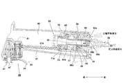
- FIG. 1 is a longitudinal sectional view of the overall configuration of a driving machine 1 according to the present embodiment.
- An outer shell (a housing in a broad sense) of the driving machine 1 includes a substantially cylindrical body portion 2a that covers a space in which a piston, which will be described later, reciprocates, and a handle portion that extends from the body portion 2a in a direction substantially orthogonal to the injection direction. 2b, a top cover 3 that covers an opening on one end side (upper side) in the axial direction of the body portion 2a, and a nose member 4 that covers an opening on the other end side (lower side) in the axial direction of the body portion 2a.
- the handle part 2b is a part that the operator holds.
- An air plug 58 is provided at the rear end of the handle portion 2b, and compressed air is supplied from an external compressor (not shown) via an air hose (not shown).
- a pressure accumulating chamber 50 for accumulating compressed air from a compressor (not shown) is formed inside the handle portion 2 b and the top cover 3.
- the nose member 4 is made of a heat-treated alloy steel material, and an injection passage 4b through which a nail driven by a driver blade (described later) passes is provided.
- An opening (not shown) for sequentially feeding nails is provided in a part of the side surface of the nose member 4, and one end side of the magazine 6 for supplying the nails is attached so as to surround the opening.
- the magazine 6 is arranged such that its longitudinal direction (feeding direction) is slightly inclined with respect to the injection direction, accommodates a roll connecting nail (not shown), and sequentially supplies the nail to the injection passage 4b. Since the structure of the magazine 6 is known, a detailed description thereof is omitted here.
- a push lever 15 is provided at the tip of the nose member 4.
- the push lever 15 is a movable member that is movable within a predetermined range in the same direction as the injection direction and in the opposite direction with respect to the nose member 4, and presses the tip 4 a that is the injection port of the nose member 4 toward the workpiece.
- the push lever 15 is positioned on the lower side as shown in FIG. 1 (second position).
- the push lever 15 moves upward (first position), and the arm portion 16a and the connecting portion 16b of the push lever 15 and the connection portion are moved.
- the push lever bush 47 is moved upward by 17 moving upward.
- the trigger 20 includes a swing shaft 22 disposed near the base of the handle portion 2b and the body portion 2a, and a trigger lever 21 that swings about the swing shaft 22.
- the meaning of pulling the trigger 20 or the trigger lever 21 means that the trigger lever 21 is moved to the side opposite to the injection direction (upward).
- the operator presses the front end (lower end) of the push lever 15 against the object to be driven into the nail (the material to be driven) and pulls the trigger lever 21 to perform an operation for driving the striking drive element including the piston 8. Can be activated to drive nails.
- the striking drive element of the driving machine 1 includes a cylindrical cylinder 10, a piston 8 that can slide up and down (reciprocate) in the cylinder 10, and a driver blade 9 connected to the piston 8. .
- the driver blade 9 is for hitting a stopper such as a nail, and is arranged so as to extend downward from the lower end side of the cylindrical cylinder 10.
- the driver blade 9 can be manufactured integrally or separately with the piston 8.
- the cylinder 10 slidably supports the piston 8 on the inner surface.
- the cylinder 10 extends radially outward in a flange shape in the opening on the upper end side, and is urged upward by a spring 14 disposed on the lower side. Held and slightly movable downward.
- the inside of the cylinder 10 is partitioned by the piston 8 into a piston upper chamber and a piston lower chamber.
- the upper chamber of the piston 8 is formed under the head cap 18 with which the upper end portion of the cylinder 10 abuts.
- the head cap 18 is provided below the valve holding member 19.
- a return air chamber 11 that stores compressed air for returning the driver blade 9 to the top dead center is formed on the lower outer periphery of the cylinder 10.
- a plurality of air holes 12a that allow inflow of compressed air in only one direction from the inside of the cylinder 10 to the outside return air chamber 11 are formed in the axially central portion of the cylinder 10, and a check is provided on the outer peripheral side thereof.
- a valve 13 is provided.
- An air hole 12 b that is always open to the return air chamber 11 is formed below the cylinder 10.
- a piston bumper which is made of an elastic body such as rubber and has a through-hole through which the driver blade 9 is inserted, in the lower end of the cylinder 10 to absorb surplus energy after nail driving due to a sudden downward movement of the piston 8. 26 is provided.
- the connecting portion of the handle portion 2b with the driving machine 1 includes a trigger lever 21 that is operated by an operator, a first switch 30 that communicates with the pressure accumulating chamber 50 and opens or closes the passage of compressed air, Is connected to the outlet side of the first switch 30, and the other is connected to the passage leading to the main valve chamber 25.
- Each of the first switch 30 and the second switch 40 includes an open / close valve that allows or blocks air flow.
- a relief valve mechanism 60 is disposed at the end of the handle portion 2b on the side away from the body portion 2a.
- the relief valve mechanism 60 is disposed between the first switch 30 that is opened and closed by the trigger lever 21 and the air plug 58, and is operated by air pressure to control the inflow of air from the air plug 58 to the pressure accumulating chamber 50. And a discharge valve for controlling the discharge of air from the pressure accumulation chamber 50 to the exhaust port 82a.
- the relief valve mechanism 60 is provided in the vicinity of the air plug 58.
- the through-holes from the pressure accumulation chamber 50 are turned on.
- High-pressure air flows through the first switch 30 and the second switch 40 through 38, reaches the main valve chamber 25, and moves the cylinder 10 downward.
- the head cap 18 and the upper opening of the cylinder 10 are separated from each other, and compressed air flows from the pressure accumulating chamber 50 in the top cover 3 into the piston upper chamber at once.
- the driver air 9 is rapidly lowered together with the piston 8 by this inflow of compressed air, the driver blade 9 slides in the injection passage 4b, and a nail (not shown) fed into the injection passage 4b is used as a material to be driven.
- FIG. 2 is an enlarged cross-sectional view showing the structure in the vicinity of the handle portion 2b of the driving machine 1 according to the present embodiment (part 1).
- the trigger mechanism of the present embodiment has a first switch 30 that is a valve mechanism that is opened and closed by the trigger lever 21 and a second switch 40 that is opened and closed by pressing the push lever 15 against the workpiece. Configured.
- the first switch 30 and the second switch 40 are connected in series in the air flow direction, and are provided with two valve means that allow or block the flow of compressed air from the pressure accumulating chamber 50 to the main valve chamber 25 (see FIG. 1). (Described later).
- the first switch 30 is a valve mechanism that opens and closes in conjunction with the operation of the trigger lever 21.
- the second switch 40 is a valve mechanism that opens and closes in conjunction with the movement of the push lever 15, and when the main body of the driving machine 1 is pressed against the material to be driven and the push lever 15 moves to the raised position, Inflow of compressed air from the first switch 30 side to the main valve chamber 25 side is allowed.
- the second switch 40 is in a cutoff state.
- a connection pipe 61 for branching from the air passage of the first switch 30 and flowing a part of the compressed air to the relief valve mechanism 60 is further provided.
- connection pipe 61 When the trigger lever 21 is pulled in the direction of the arrow 24, a part of the compressed air is supplied to the connection pipe 61, and when the trigger lever 21 is released (when the trigger lever 21 moves in the direction opposite to the arrow 24), the connection pipe It is configured to release the air pressure 61 and return it to almost atmospheric pressure.
- the relief valve mechanism 60 is provided in an inner portion of the substantially cylindrical handle portion 2b, and is a relief valve piston 65 movable in the axial direction of the handle portion 2b, and a substantially cylindrical relief valve case that houses the relief valve piston 65. 70 and a cap 80 that closes one of the opening surfaces of the relief valve case 70.
- the relief valve piston 65 is a discharge valve that operates using the pressure of air. When the inflow of air reaches a certain amount, the air in the pressure accumulating chamber 50 is discharged to the outside at once, and when the timer time elapses. It functions as a timer valve that operates.
- An air plug 58 for connecting a hose (not shown) for supplying compressed air is attached to the cap 80.
- connection pipe 61 One end of the connection pipe 61 is connected to the air flow path of the first switch 30, and the other end is connected to the opening 71 b of the relief valve case 70.
- the relief valve mechanism 60 When the relief valve mechanism 60 is not discharging the air from the pressure accumulation chamber 50 to the atmosphere, the air supplied from the air plug 58 passes through the internal space of the cap 80 and the relief valve piston 65 as shown by the arrow. It flows into the pressure accumulating chamber 50. As a result, the pressure accumulation chamber 50 is maintained at a high air pressure supplied from an external compressor or the like.
- FIG. 3 is an enlarged cross-sectional view of the vicinity of the trigger of FIG. 2, in which the first switch 30 is in an ON state (a state where the air passage is communicated), and the second switch 40 is in an OFF state (the air passage is shut off). State).
- Two cylindrical holes extending upward from below are formed in the lower part near the base of the handle part 2b.
- the first switch 30 is accommodated inside the two cylindrical holes on the side far from the cylinder 10
- the second switch 40 is accommodated inside the side near the cylinder 10.
- the trigger lever 21 is counterclockwise about the rocking shaft 22 against the urging force of the U-shaped thin plate spring 23 provided to move around the rocking shaft 22 by the operator's pulling operation. That is, it can move upward.
- the thin plate spring 23 when the upper plate 23b abuts on the lower surface of the trigger bush 32, the lower plate 23a abuts on the upper surface of the trigger lever 21, and the operator releases the trigger lever 21, it rotates clockwise in the figure. , The trigger plunger 31 is moved downward.
- the compressed air stored in the pressure accumulating chamber 50 flows into the first valve chamber 34 through the through hole 38 in the direction of the arrow 46a.
- the air that has passed through the first switch 30 flows into the second valve chamber 44 on the second switch 40 side through the air passage 39 as indicated by an arrow 46b.
- the push lever valve 42 which is the valve mechanism of the second switch 40, moves upward, so that compressed air passes through the opening 43 serving as the valve portion, as indicated by an arrow 46c. Compressed air is discharged from the through hole 47a and flows into the main valve chamber 25 (see FIG. 1).
- the compressed air on the pressure accumulating chamber 50 side controls the start of the driving operation by the piston 8 as the striking drive means by passing through the two switch means (valve mechanisms that block the air flow) connected in series.
- the first switch 30 is mainly configured by a substantially cylindrical trigger bush 32, a trigger plunger 31 disposed in the trigger bush 32, and a substantially spherical valve member 35.
- the trigger bush 32 is screwed to a female screw formed on the cylindrical hole side by a male screw formed on the outer peripheral side near the lower side.
- a packing 36 is interposed at the upper end portion of the trigger bush 32.
- the valve member 35 is accommodated in the first valve chamber 34 communicating with the pressure accumulating chamber 50 and the air passage 39, and opens or opens the step-shaped opening 34a formed in the inner diameter portion of the substantially cylindrical trigger bush 32. By closing, the air passage is blocked or opened.
- the diameter of the opening 34 a is smaller than the diameter of the valve member 35.
- the valve member 35 is always urged in the direction of the arrow 46a by the action of compressed air on the pressure accumulation chamber 50 side. Therefore, when the valve member 35 receives a downward pressure due to the pressure of the compressed air in the pressure accumulating chamber 50 through the through hole 38, the valve member 35 is locked to the opening 34a and the first valve chamber 34 is closed. . That is, the first switch 30 is in a closed state (OFF).
- the trigger plunger 31 is held below the valve member 35 so as to be movable up and down.
- a tip 31c of the trigger plunger 31 is an action piece for moving the valve member 35, and a portion having a substantially cross-shaped cross section perpendicular to the axial direction is formed near the center.
- a predetermined space is formed in the shaft to allow an air flow in the axial direction.
- the check valve 33 can be formed of, for example, a cylindrical rubber member that is continuous in the circumferential direction, and most of the opening 32a communicates with the air passage 39, but a part of the air enters the through hole 37 by the longitudinal groove 32d. Also flows. Therefore, when the opening 34a is opened, the compressed air that has flowed in as indicated by the arrow 46a is directed to the direction of the arrow 46b via the air passage 39 and to the connection pipe 61 side via the longitudinal groove 32d and the through hole 37. It branches and flows like 46d.
- connection pipe 61 is an air passage that supplies a part of the compressed air to the relief valve mechanism 60 side when the trigger lever 21 is pulled, and is constituted by a metal or synthetic resin pipe.
- the connection portion of the connection pipe 61 to the through hole 37 is sealed by the O-ring 62 so that the high pressure air in the pressure accumulating chamber 50 is not mixed into the connection pipe 61.
- the second switch 40 is disposed inside a cylindrical hole on the side close to the cylinder 10, and a thin diameter portion and a thick diameter portion are formed in the cylindrical hole.
- the second switch 40 is a substantially cylindrical push lever plunger 41 press-fitted into a thick diameter portion, a push lever valve 42 disposed in the push lever plunger 41, and a push lever valve 42 in a predetermined direction. It is mainly configured by a coiled plunger spring 45.
- the push lever valve 42 is a valve that switches between blocking or circulating the flow of compressed air from the air passage 39 to the through hole 47 a according to the operation of the push lever 15.
- the push lever plunger 41 is formed in a tubular shape extending substantially up and down and having a passage inside, and the flange 43 of the push lever valve 42 is brought into contact with the opening 43 formed at the upper end of the push lever plunger 41. (The state shown in FIG. 3), the push lever valve 42 moves upward, and the flange-like portion moves away from the opening 43 to allow air flow.
- a through hole 47 a is formed on the outer peripheral side below the opening 43. The through hole 47a serves as an outlet of the flow path from the second valve chamber 44 and is connected to the main valve chamber 25 (see FIG. 1).
- the push lever valve 42 moves in the vertical direction, and opens or closes the opening 43 at the upper end of the push lever plunger 41. About half of the push lever valve 42 is accommodated in the space above the cylindrical push lever plunger 41 and moves so as to close or open the opening 43.
- the push lever valve 42 is formed with a cylindrical portion 42a on the upper side, a flange portion is formed near the center in the axial direction, and a lower portion is formed with a recess 42b having a cross-shaped cross section. Air flows from the second valve chamber 44 to the through hole 47a through a gap between the recess 42b and the inner wall surface of the push lever plunger 41.
- a groove portion that is continuous in the circumferential direction for arranging a seal member such as an O-ring is formed below the flange portion.
- the cylindrical portion 42 a is disposed inside the coiled plunger spring 45. In this way, the flow path of the second switch 40 can be closed with the lower surface of the flange portion in contact with the upper surface of the stepped opening 43 (the state shown in FIG. 3).
- the push lever valve 42 is urged downward by the plunger spring 45, and moves upward against the urging force of the plunger spring 45 when the push lever plunger 41 is pressed.
- One end of the plunger spring 45 is held on the housing 2 side, and the other end abuts against the upper surface of the flange portion of the push lever valve 42.
- the push lever bush 47 moves up and down together with the push lever 15 to move the push lever valve 42.
- the driver blade 9 fixed to the piston 8 strikes the leading nail (not shown) fed from the magazine 6 to the injection passage 4b and strikes the tip of the nose member 4 into the driven member.
- the first switch 30 or the second switch 40 is turned off by either releasing the trigger lever 21 or releasing the push lever 15 after driving the nail, the pressure accumulation chamber 50 side The supply of compressed air to the cylinder 10 is interrupted.
- the premise of the driving machine provided with the relief valve mechanism 60 is premised on the presence of the first switch 30 that operates by the push lever 15 and the trigger lever 21, but in addition to the first switch 30, Whether or not the second switch 40 is provided is arbitrary, and even if the second switch 40 is not provided, the first switch 30 does not operate unless the push lever 15 is pressed. Any other switch mechanism may be used as long as it has a “repetitive driving mode” in which the main body of the driving machine 1 is moved up and down while the operation is maintained and the stopper is continuously driven.
- the trigger lever 21 In the “single shot mode”, after one shot is completed, the trigger lever 21 is once released to be in the trigger-off state, and then the next shot is not performed unless the trigger lever 21 is pulled again (of course, the next shot operation). It is an essential condition that the push lever 15 is sometimes pressed against the workpiece.
- the “repetitive driving mode” after the operator completes the first driving, the trigger lever 21 is pulled without returning and the main body of the driving machine 1 is moved to move the next driving material. When the push lever 15 is pressed against the driving position, the nail can be driven at that time. That is, if the trigger lever 21 is pulled without returning after the driving is completed, the first switch 30 is kept on and the flow of compressed air on the second switch 40 side is maintained.
- Providing the “repetitive driving mode” in this way is very convenient and convenient for work in which many nails are driven continuously. This is because the trigger lever 21 is kept pulled and the push lever 15 is simply positioned and pressed to the next driving position. However, when the operator has such a repetitive driving habit, when performing an operation in which the driving position is carefully determined following the continuous driving, the driving position is finely adjusted without returning the trigger lever 21. In some cases, a shot (miss shot) may be made at a position slightly deviated from a desired shot position.
- the air in the pressure accumulating chamber 50 is forcibly forced after a predetermined time has elapsed. After that, it was made impossible to fire repeatedly. However, if the air in the pressure accumulating chamber 50 is exhausted without the operator's knowledge, it will not be possible to drive in the event that the next nailing happens to be delayed in the event that the next nailing happens to be delayed. There is a fear.
- the pulling state of the trigger lever 21 can be prevented from being inadvertently maintained, so that miss shots can be reduced, and continuous driving work is interrupted.
- the subsequent nail operation can be continued without any trouble by once releasing the trigger lever.
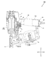
- FIG. 4 is an enlarged cross-sectional view showing the structure in the vicinity of the handle portion 2b of the driving machine 1 according to the embodiment of the present invention, and shows a state in which a preliminary notification sound is sounded.
- several seconds have passed after the trigger lever 21 is pulled from the state in which the pressure inside the pressure accumulating chamber 50 has returned to a predetermined high pressure state after the nailing is performed in the “continuous driving mode”. Indicates the state. Since the trigger lever 21 remains pulled after completion of the previous driving operation, the compressed air in the pressure accumulating chamber 50 flows as shown by the arrow 51 and flows through the connection pipe 61 to open the relief valve case 70 from the opening 71b. It flows into the internal space.
- the inflowing air flows into the space (air chamber 73) on the front side of the flange portion 65a of the relief valve piston 65.
- a predetermined force PS is applied by the pressure of the air that has flowed in, and a force that moves the relief valve piston 65 backward acts.
- the relief valve piston 65 is urged forward by a spring 77 on the rear side of the flange portion 65a. Therefore, the force F acts from the rear side of the flange portion 65a, and the relief valve piston 65 stops at a position where the force PS and the force F are equal.
- the rear end portion 65d of the cylindrical relief valve piston 65 is closed, and a through hole 65b and a through hole 65c communicating from the inner space to the outer space are formed.
- the through hole 65b is as shown in FIG. It becomes an inflow passage from the air plug 58 side to the pressure accumulating chamber 50.
- the through hole 65c is a passage for discharging a part of the air in the pressure accumulating chamber 50 to the outside.
- FIG. 5 is an enlarged view of the vicinity of the relief valve mechanism 60 of FIG.
- the relief valve case 70 is formed in a cup shape, and is mounted from the opening on the rear side of the cylindrical handle portion 2b toward the inside on the front side.
- a large through hole 71a for allowing air to pass is formed in a bottom surface portion located on the front side, and a side wall portion includes a narrow diameter portion 70a, a medium diameter portion 70b, and a large diameter portion 70c having a small outer diameter.
- the periphery of the opening surface is formed in a flange portion 70d extending so as to extend radially outward.
- a packing 69 is interposed between the flange portion 70d and the end portion of the handle portion 2b, and is fixed by a screw 72.
- the inner space of the cylindrical relief valve case 70 is a sliding space for the relief valve piston 65 to move in the front-rear direction.
- a plurality of O-rings 66 a to 66 e are provided between the outer wall of the relief valve piston 65 and the inner wall of the relief valve case 70 or the cap 80.
- An O-ring 66 f is also provided near the rear end of the outer wall of the relief valve piston 65 and in contact with the air plug 58.
- An O-ring 84 is also provided between the outer peripheral side of the cap 80 and the relief valve case 70.
- the relief valve is opened from the air plug 58 side by the relative positional relationship between the through holes 65b and 65c formed in the substantially cylindrical relief valve piston 65 whose one end is closed and the passage formed on the inner peripheral side of the cap 80.
- the inflow of air into the internal space of the piston 65 and the release of air from the internal space of the relief valve piston 65 to the atmosphere via the cap 80 are controlled.
- the relief valve piston 65 acts as an on-off valve for the air inlet passage and outlet passage.
- the cap 80 serves as a fixing member for holding the rear side of the relief valve piston 65 and holding the air plug 58.
- the relief valve case 70, the relief valve piston 65, and the cap 80 can be manufactured as a single piece of metal or a single piece of synthetic resin.
- An annular groove 81 that is continuous in the circumferential direction is formed on the inner peripheral surface of the cap 80, and an air passage 82 that penetrates from a part of the annular groove 81 (upward here) toward the rear side is formed. .
- the remote end of the annular groove 81 of the atmospheric passage 82 is an exhaust port 82a that communicates with the atmosphere.
- An oblique narrow passage 83 is formed from the other part of the annular groove 81 (downward here) to the front side.
- An annular groove 85 that is continuous in the circumferential direction is formed on the front side of the passage 83.
- the cross-sectional shape of the annular groove 85 (the cross section viewed as shown in FIG. 5) is a trapezoid, and a through hole 65c is adjacent to the inside.
- a plurality of through-holes 65c are formed in the circumferential direction, and the outer peripheral side is partially thinned in cross-sectional shape, and an O-ring 66c is disposed in the narrowed portion.
- the spring pressure adjusting ring 78 is spline-coupled to the cap 80, and the rear end side is held by an elastic bumper 79 such as a rubber ring.
- the elastic bumper 79 is disposed so as to hit the stepped portion 80 b of the cap 80.
- the cap 80 is configured so as to be able to rotate in the rotational direction, although it is held so as not to come out rearward in the axial direction from the relief valve case 70.
- the outer peripheral surface of the spring pressure adjusting ring 78 is a male screw
- the inner peripheral portion of the relief valve case 70 (the inner peripheral side portion of the large diameter portion 70c) facing the spring pressure adjusting ring 78 is a female screw.
- the spring pressure adjusting ring 78 can also be rotated to adjust its axial direction.
- the strength of the urging force of the relief valve piston 65 by the spring 77 can be adjusted, and the time from when the trigger lever 21 is pulled until the notification sound starts or until the compressed air is discharged. It functions as a mechanism for adjusting the time required.
- the opening area of the exhaust port 82a is appropriately set so that, during exhaust, for example, a sound such as “shoe” leaking from the air can be sufficiently heard by the operator in noise during normal work. This sound should not be too loud and should not be annoying.
- a member such as a whistle may be added to the exhaust port 82a, or a further through hole that intersects the discharge direction of the atmospheric passage 82 may be formed so that a loud sound is produced by the principle of the whistle. This sound may be generated not only for a moment but for a certain time, for example, about 3 to 5 seconds. Then, when the notification sound is sounding, the operator can easily determine whether to perform the next nail driving operation or return the trigger lever 21.
- the trigger lever 21 is returned to the operator by releasing a part of the compressed air into the atmosphere after a predetermined time elapses after the nail is finished, for example, about 3 to 5 seconds. It is possible to make a notification by the sound of not being performed.
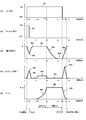
- FIG. 7 (1) to (5) the horizontal axis represents time (unit: second), and the horizontal axes are shown together.
- the driving mode of the driving machine 1 is a continuous driving mode.
- (1) shows the operation of the trigger lever 21 (trigger operation 91). In Kokoko and trigger lever 21 much is subtracted from the beginning of time t 1 of nailing the last operation by the operator, the drawn state continues until time t 5.
- FIG. 7B is a diagram illustrating the state of the push lever 15.
- the operator pulls the trigger lever 21 and simultaneously presses the tip (lower end) of the push lever 15 against an object (a material to be driven) into which the nail is to be driven. Then the push lever 92, the driving operation of the nail turned on at time t 1 is carried out. Since the nail is driven body driving machine 1 by the reaction moves away from the driving material, the push lever 15 is turned off at time t 2. At the point in time t 2, the driving of the nail has been completed.
- FIG. 7 (3) shows the pressure accumulation chamber pressure 93, and the vertical axis is the pressure (unit Pa).
- the pressure P returns to the predetermined pressure P at the arrow 93b.
- FIG. 7 (4) shows the flow rate of air flowing from the external compressor through the air plug 58.
- the pressure accumulating chamber 50 is not air inflow due to the predetermined high pressure P.
- FIG. 6 (5) is a graph showing the force acting on the flange portion 65 a of the relief valve piston 65, that is, the size 95 of P ⁇ S.
- P 1 is the pressure of the air chamber 73
- S is the cross-sectional area of the front side of the flange portion 65a.
- P ⁇ S as shown by the arrow 95a together with air begins to leak to the outside is increased.
- P 1 ⁇ S for preventing inflow from the air plug 58 is reached.
- the notification lever 15 when the push lever 15 is in the second position, the notification lever is made to emit a notification sound when the trigger lever 21 remains pulled for more than the first time. If it continues only for time, the air in the pressure accumulating chamber is exhausted to the outside at once, and the pressure in the pressure accumulating chamber is lowered. Therefore, it is possible to direct the operator not to pull the push lever 15 more than necessary. Since the notification function by the notification sound is generated by discharging a part of the air in the pressure accumulating chamber, it is not necessary to provide an electrical component. Moreover, it can be realized relatively easily by installing the connection pipe 61 and the relief valve mechanism 60 inside the handle portion of the conventional driving machine.
- the relief valve mechanism 60 is realized by the trigger mechanism using the two trigger valve mechanisms of the first switch 30 and the second switch 40, but the configuration on the trigger valve mechanism side is not limited thereto, As long as the trigger mechanism can guide the compressed air to the connection pipe 61 in conjunction with the ON state of the trigger switch, the present invention can be similarly applied to a so-called one-valve type trigger mechanism.
- the relief valve mechanism 60 is disposed in the handle portion 2b at a location where the air plug 58 is attached.
- the relief valve mechanism 60 may be provided at any position, and the inflow of air from the air plug. As long as a relief mechanism that can control the discharge of air in the pressure accumulating chamber in conjunction with each other can be realized, a configuration other than the above-described embodiment may be adopted.
- the “sound” using the discharge of compressed air is exemplified as the notification unit.
- a rotating member an impeller having a weight eccentric to the discharge path of the compressed air
- the body particularly the handle portion
- a rotating member such as an impeller
- Notification may be made by not providing a sound from a piezoelectric buzzer or a speaker using an electromotive force generated by rotation provided in the discharge path, or by light emission of an LED or the like provided at a position easy for the user to see.
- Oscillating shaft 23 ... Thin plate spring, 23a ... Lower plate, 23b ... Upper plate, 25 ... Main valve chamber , 26 ... piston bumper, 30 ... first switch, 31 ... trigger plunger, 31c ... tip, 32 ... trigger bush, 32a ... opening, 32b ... radial groove, 32c ... longitudinal hole, 32d ... Directional groove 33 ... Check valve 34 ... First valve chamber 34a ... Opening 35 ... Valve member 36 ... Packing 37 ... Through hole 38 ... Through hole 39 ... Air passage 40 ... Second switch , 41 ... push lever plunger, 42 ... push lever valve, 42a ... cylindrical portion, 42b ... hollow portion, 43 ... opening, 44 ... second valve chamber, 45 ...
- plunger spring 47 ... push lever bush, 47a ... through hole 48 ... Push lever bush cover, 50 ... Pressure accumulation chamber, 58 ... Air plug, 58a ... Narrow inner wall part, 58b ... Thick inner wall part, 60 ... Relief valve mechanism, 61 ... Connection pipe, 61a ... Internal space of (connection pipe), 62 ... O-ring, 65 ... Relief valve piston, 65a ... Flange portion, 65b ... Through hole, 65c ... Through hole, 65d ... Rear end, 66a to 66f ... Ring, 69 ... packing, 70 ... relief valve case, 70a ... small diameter part, 70b ... medium diameter part, 70c ... large diameter part, 70d ...
Abstract
Description
Claims (14)
- ハウジングと、前記ハウジング内部に設けられた圧縮空気を蓄える蓄圧室と、圧縮空気によりシリンダ内で往復動するピストンと、前記ピストンに接続された止具を打込むドライバブレードと、前記ドライバブレードの移動方向と平行な方向に移動可能に支持され、前記止具の射出口の先端を被打込み材に向かって押し当てる方向に移動させた時に第一の位置に移動し、前記止具の射出口の先端を被打込み材に押し当てていないときに第二の位置に移動するプッシュレバーと、前記蓄圧室の空気の排出を制御するスイッチ機構を動作させるトリガと、前記プッシュレバーを第一の位置に移動させた状態かつ前記トリガが引かれた状態において、前記蓄圧室と前記ピストンの上室を連通させることによって、前記蓄圧室内の圧縮空気が前記シリンダに流入することにより打撃を行う打込機において、前記プッシュレバーが前記第二の位置にあるときに前記トリガを引いたままの状態において圧縮空気により制御される排出弁を有し、前記蓄圧室内の圧縮空気の少なくとも一部を前記排出弁により外部に排出させる排出機構を具備したことを特徴とする打込機。
- 前記蓄圧室内の空気の一部を外部に排出させることによりお知らせ音が発せられることを特徴とする請求項1に記載の打込機。
- 前記お知らせ音が発せられている状態でさらに前記トリガを引いたままの状態が継続されたら、前記蓄圧室の空気を一気に外部に排出させることにより前記蓄圧室の圧力を低下させるリリーフバルブ機構を設けたことを特徴とする請求項2に記載の打込機。
- 前記ハウジングは略円筒状の胴体部と、該胴体部から略直交方向に延びるハンドル部を有し、外部から圧縮空気を供給するためのエアプラグを前記ハンドル部の前記胴体部から離れた端部に設け、前記リリーフバルブ機構は前記エアプラグと前記トリガの間の空間に配置されることを特徴とする請求項3に記載の打込機。
- 前記リリーフバルブ機構に、前記エアプラグから前記蓄圧室までの流入経路の開閉弁と、前記蓄圧室内の空気を外部に排出させる排出経路の前記排出弁を設け、前記お知らせ音を発する際には前記流入経路は開放したままとし、前記蓄圧室の空気を一気に外部に排出させる際には前記流入経路を閉じるようにしたことを特徴とする請求項4に記載の打込機。
- 前記蓄圧室の空気を一気に外部に排出させた後には、前記トリガが引かれた状態が解除されるまで,前記流入経路を閉じた状態を維持することを特徴とする請求項5に記載の打込機。
- 前記リリーフバルブ機構は、前記流入経路の開閉弁と前記排出経路の前記排出弁を兼用するリリーフバルブピストンと、前記リリーフバルブピストンが摺動する空間を画定すると共に流入通路と排出通路を形成するリリーフバルブケースを有し、前記リリーフバルブピストンの移動をおこなうために、前記リリーフバルブピストンと前記リリーフバルブケースとの間の空気室に対して前記トリガから圧縮空気の一部が供給される接続経路を設けたことを特徴とする請求項6に記載の打込機。
- ハウジングと、前記ハウジング内部に設けられた圧縮空気を蓄える蓄圧室と、圧縮空気によりシリンダ内で往復動するピストンと、前記ピストンに接続された止具を打込むドライバブレードと、前記ドライバブレードの移動方向と平行な方向に移動可能に支持され、前記止具の射出口の先端を被打込み材に向かって押し当てる方向に移動させた時に第一の位置に移動し、前記止具の射出口の先端を被打込み材に押し当てていないときに第二の位置に移動するプッシュレバーと、前記蓄圧室の空気の排出を制御するスイッチ機構を動作させるトリガと、前記プッシュレバーを第一の位置に移動させた状態かつ前記トリガが引かれた状態において、前記蓄圧室と前記ピストンの上室を連通させることによって、前記蓄圧室内の圧縮空気が前記シリンダに流入することにより打撃を行う打込機において、前記蓄圧室に圧縮空気を供給するエアプラグを前記ハウジングに設け、前記蓄圧室の圧縮空気を排出する排出口を設け、空気圧によって動作し前記排出口の開閉を行うリリーフバルブを前記エアプラグの近傍に設け、前記トリガが引かれたときに前記リリーフバルブ側に圧縮空気の一部を供給する空気通路を設け、前記空気通路により前記リリーフバルブに所定の量の空気が流れてバルブ室の圧力を徐々に上昇させて、前記リリーフバルブに作用する空気圧が高くなったら前記蓄圧室内の圧縮空気を前記ハウジングの外部に排出させることを特徴とする打込機。
- 前記リリーフバルブは、リリーフバルブピストンを有し、前記リリーフバルブは前記空気通路から供給される空気の圧力を受ける空気室と、前記リリーフバルブピストンを前記圧力と反対方向に付勢する付勢手段と、前記エアプラグから前記蓄圧室までの圧縮空気の流入通路を有し、前記リリーフバルブは、前記蓄圧室内の圧縮空気を前記ハウジングの外部に排出させる際に、前記排出口を開放すると共に前記流入通路を閉鎖することを特徴とする請求項8に記載の打込機。
- 前記トリガの操作開始時から前記圧縮空気の排出までに要する時間の調整機構を設けたことを特徴とする請求項9に記載の打込機。
- 前記圧縮空気の排出後に前記トリガが戻されたら、前記バルブ室の空気を大気中に放出することにより、前記排出口を閉鎖すると共に前記流入通路を開放することを特徴とする請求項10に記載の打込機。
- ハウジングと、 前記ハウジング内部に設けられた圧縮空気を蓄える蓄圧室と、外部の接続ホースから圧縮空気を前記蓄圧室に供給するためのエアプラグと、圧縮空気によりシリンダ内で往復動するピストンと、前記ピストンに接続された止具を打込むドライバブレードと、前記ドライバブレードの移動方向と平行な方向に移動可能に支持され、前記止具の射出口の先端を被打込み材に向かって押し当てる方向に移動させた時に第一の位置に移動し、前記止具の射出口の先端を被打込み材に押し当てていないときに第二の位置に移動するプッシュレバーと、前記蓄圧室の空気の排出を制御するスイッチ機構を動作させるトリガと、前記プッシュレバーを第一の位置に移動させた状態かつ前記トリガが引かれた状態において、前記蓄圧室と前記ピストンの上室を連通させることによって、前記蓄圧室内の圧縮空気が前記シリンダに流入することにより打撃を行う打込機において、前記エアプラグから前記蓄圧室への空気通路の遮断と前記蓄圧室から大気中への圧縮空気の排出口の開閉を行う空気動作タイマー弁を設け、前記プッシュレバーが前記第二の位置にあるときに前記トリガが引かれたままの状態が所定時間以上継続したら、前記空気動作タイマー弁によって前記蓄圧室内の圧縮空気を外部に開放させると共に前記エアプラグから前記蓄圧室への空気通路を遮断することを特徴とする打込機。
- 前記所定時間が継続する直前に、前記空気動作タイマー弁に流入する空気の一部を前記ハウジングの外部に漏らすことにより、空気漏洩音によって前記蓄圧室の排気動作を作業者に予告することを特徴とする請求項12に記載の打込機。
- 前記空気漏洩音が所定時間以上鳴り続いた後に、前記蓄圧室内の圧縮空気を外部に開放させると共に前記エアプラグから前記蓄圧室への空気通路を遮断することを特徴とする請求項13に記載の打込機。
Priority Applications (4)
| Application Number | Priority Date | Filing Date | Title |
|---|---|---|---|
| JP2018514220A JP6575679B2 (ja) | 2016-04-28 | 2017-03-31 | 打込機 |
| EP17789180.1A EP3450108B1 (en) | 2016-04-28 | 2017-03-31 | Driving device |
| US16/097,268 US11229996B2 (en) | 2016-04-28 | 2017-03-31 | Fastening tool |
| CN201780026151.6A CN109070322B (zh) | 2016-04-28 | 2017-03-31 | 打钉机 |
Applications Claiming Priority (2)
| Application Number | Priority Date | Filing Date | Title |
|---|---|---|---|
| JP2016-090365 | 2016-04-28 | ||
| JP2016090365 | 2016-04-28 |
Publications (1)
| Publication Number | Publication Date |
|---|---|
| WO2017187892A1 true WO2017187892A1 (ja) | 2017-11-02 |
Family
ID=60160346
Family Applications (1)
| Application Number | Title | Priority Date | Filing Date |
|---|---|---|---|
| PCT/JP2017/013670 WO2017187892A1 (ja) | 2016-04-28 | 2017-03-31 | 打込機 |
Country Status (6)
| Country | Link |
|---|---|
| US (1) | US11229996B2 (ja) |
| EP (1) | EP3450108B1 (ja) |
| JP (1) | JP6575679B2 (ja) |
| CN (1) | CN109070322B (ja) |
| TW (1) | TWI771298B (ja) |
| WO (1) | WO2017187892A1 (ja) |
Cited By (4)
| Publication number | Priority date | Publication date | Assignee | Title |
|---|---|---|---|---|
| WO2019167497A1 (ja) * | 2018-02-28 | 2019-09-06 | 工機ホールディングス株式会社 | 打込機 |
| WO2021192838A1 (ja) * | 2020-03-24 | 2021-09-30 | 株式会社マキタ | 打ち込み工具 |
| JP7435311B2 (ja) | 2020-06-30 | 2024-02-21 | マックス株式会社 | 空気圧工具 |
| JP7435312B2 (ja) | 2020-06-30 | 2024-02-21 | マックス株式会社 | 空気圧工具 |
Families Citing this family (8)
| Publication number | Priority date | Publication date | Assignee | Title |
|---|---|---|---|---|
| US10800022B2 (en) * | 2017-02-09 | 2020-10-13 | Illinois Tool Works Inc. | Powered-fastener-driving tool including a driver blade having a varying cross-section |
| US10654160B2 (en) * | 2017-06-20 | 2020-05-19 | Miner Elastomer Products Corporation | Nail gun recoil bumper |
| JP7114934B2 (ja) * | 2018-03-01 | 2022-08-09 | マックス株式会社 | 空気圧工具 |
| EP3698925B1 (en) * | 2019-02-22 | 2021-10-06 | Max Co., Ltd. | Pneumatic tool |
| TWI734418B (zh) * | 2020-03-18 | 2021-07-21 | 力肯實業股份有限公司 | 氣動釘槍的氣路結構 |
| TWI734417B (zh) * | 2020-03-18 | 2021-07-21 | 力肯實業股份有限公司 | 氣動釘槍的氣路結構 |
| JP7435310B2 (ja) * | 2020-06-30 | 2024-02-21 | マックス株式会社 | 空気圧工具 |
| TWI771006B (zh) * | 2021-05-18 | 2022-07-11 | 力肯實業股份有限公司 | 氣動釘槍的氣路結構 |
Citations (6)
| Publication number | Priority date | Publication date | Assignee | Title |
|---|---|---|---|---|
| JPS50128780U (ja) * | 1974-04-03 | 1975-10-22 | ||
| JPS51148873A (en) * | 1975-03-12 | 1976-12-21 | Senco Products | Tool for attaching fasteners by air pressure operation |
| JPS5786776U (ja) * | 1980-11-17 | 1982-05-28 | ||
| JPH0261580U (ja) * | 1988-10-24 | 1990-05-08 | ||
| JPH0270980U (ja) * | 1988-11-17 | 1990-05-30 | ||
| JP2002254348A (ja) * | 2001-01-16 | 2002-09-10 | Illinois Tool Works Inc <Itw> | 空圧式締結具駆動工具 |
Family Cites Families (33)
| Publication number | Priority date | Publication date | Assignee | Title |
|---|---|---|---|---|
| JPS50128780A (ja) | 1974-03-30 | 1975-10-11 | ||
| JPS5786776A (en) | 1980-11-20 | 1982-05-29 | Citizen Watch Co Ltd | Construction to connect watch band to case of wrist watch |
| US4405071A (en) * | 1981-09-14 | 1983-09-20 | Duo-Fast Corporation | Fastener driving tool |
| US4834131A (en) * | 1987-11-10 | 1989-05-30 | Duo-Fast Corporation | Safety system for pneumatic tools |
| JPH0261580A (ja) | 1988-08-29 | 1990-03-01 | Nec Corp | レーダビデオ帯域圧縮装置 |
| JPH0270980A (ja) | 1988-09-06 | 1990-03-09 | Nippon Denso Co Ltd | 内燃機関のノッキング制御装置 |
| JP2560432Y2 (ja) * | 1993-09-06 | 1998-01-21 | マックス株式会社 | 釘打機用安全装置 |
| US5531279A (en) * | 1994-04-12 | 1996-07-02 | Indresco Inc. | Sensor impulse unit |
| US6745928B2 (en) * | 2000-01-24 | 2004-06-08 | Hitachi Co., Ltd | Trigger valve apparatus for pneumatic tool |
| US6161628A (en) * | 2000-04-28 | 2000-12-19 | Q.C. Witness Int. Co., Ltd. | Pneumatic tool |
| US7225959B2 (en) * | 2001-04-30 | 2007-06-05 | Black & Decker, Inc. | Portable, battery-powered air compressor for a pneumatic tool system |
| US7494035B2 (en) * | 2001-04-30 | 2009-02-24 | Black & Decker Inc. | Pneumatic compressor |
| US6523621B1 (en) * | 2001-08-31 | 2003-02-25 | Illinois Tool Works Inc. | Delay-interruption connector for pneumatic tool |
| US7191927B2 (en) * | 2005-06-13 | 2007-03-20 | Illinois Tool Works Inc. | Fastener-driving tool having trigger control mechanism for alternatively permitting bump firing and sequential firing modes of operation |
| TW200700196A (en) * | 2005-06-28 | 2007-01-01 | Basso Ind Corp | Pressure-relief device of a nailer |
| CN2871118Y (zh) * | 2006-02-16 | 2007-02-21 | 杨耀德 | 打钉枪安全装置 |
| CA2669183A1 (en) * | 2006-11-09 | 2008-05-22 | Stanley Fastening Systems, L.P. | Cordless fastener driving device |
| JP4964624B2 (ja) | 2007-03-06 | 2012-07-04 | 株式会社マキタ | 打ち込み機 |
| CN101712148B (zh) | 2008-09-30 | 2013-07-10 | 株式会社牧田 | 气动工具 |
| JP5589804B2 (ja) | 2010-11-30 | 2014-09-17 | 日立工機株式会社 | 打込機 |
| US8695863B2 (en) | 2011-05-10 | 2014-04-15 | Illinois Tool Works, Inc. | Reinforced plastic sleeve for pneumatic nailer |
| US9770818B2 (en) * | 2011-10-03 | 2017-09-26 | Illinois Tool Works Inc. | Fastener driving tool with portable pressurized power source |
| JP5855518B2 (ja) | 2012-04-24 | 2016-02-09 | 株式会社マキタ | 打ち込み工具 |
| JP2014008566A (ja) | 2012-06-29 | 2014-01-20 | Hitachi Koki Co Ltd | 打込機 |
| US20140090732A1 (en) * | 2012-09-30 | 2014-04-03 | Illinois Tool Works Inc. | Compact pneumatic nailer with supplemental air tank |
| JP2014233770A (ja) * | 2013-05-31 | 2014-12-15 | 日立工機株式会社 | 打込機 |
| DE102013106657A1 (de) * | 2013-06-25 | 2015-01-08 | Illinois Tool Works Inc. | Eintreibwerkzeug zum Eintreiben von Befestigungsmitteln in ein Werkstück |
| DE102013106658A1 (de) * | 2013-06-25 | 2015-01-08 | Illinois Tool Works Inc. | Eintreibwerkzeug zum Eintreiben von Befestigungsmitteln in ein Werkstück |
| TWM473908U (zh) * | 2013-10-04 | 2014-03-11 | Basso Ind Corp | 氣動釘槍之壓源控制裝置 |
| CN108602179B (zh) * | 2015-12-28 | 2021-07-16 | 工机控股株式会社 | 打入机 |
| JP6819045B2 (ja) * | 2016-01-26 | 2021-01-27 | 工機ホールディングス株式会社 | 打込機 |
| US11267116B2 (en) * | 2016-11-30 | 2022-03-08 | Koki Holdings Co., Ltd. | Drive-in machine |
| EP3666469B1 (de) * | 2018-12-12 | 2024-03-27 | BeA GmbH | Druckluftnagler mit einer sicherheitseinrichtung |
-
2017
- 2017-03-31 CN CN201780026151.6A patent/CN109070322B/zh not_active Expired - Fee Related
- 2017-03-31 US US16/097,268 patent/US11229996B2/en active Active
- 2017-03-31 JP JP2018514220A patent/JP6575679B2/ja active Active
- 2017-03-31 EP EP17789180.1A patent/EP3450108B1/en active Active
- 2017-03-31 WO PCT/JP2017/013670 patent/WO2017187892A1/ja active Application Filing
- 2017-04-27 TW TW106114045A patent/TWI771298B/zh active
Patent Citations (6)
| Publication number | Priority date | Publication date | Assignee | Title |
|---|---|---|---|---|
| JPS50128780U (ja) * | 1974-04-03 | 1975-10-22 | ||
| JPS51148873A (en) * | 1975-03-12 | 1976-12-21 | Senco Products | Tool for attaching fasteners by air pressure operation |
| JPS5786776U (ja) * | 1980-11-17 | 1982-05-28 | ||
| JPH0261580U (ja) * | 1988-10-24 | 1990-05-08 | ||
| JPH0270980U (ja) * | 1988-11-17 | 1990-05-30 | ||
| JP2002254348A (ja) * | 2001-01-16 | 2002-09-10 | Illinois Tool Works Inc <Itw> | 空圧式締結具駆動工具 |
Non-Patent Citations (1)
| Title |
|---|
| See also references of EP3450108A4 * |
Cited By (9)
| Publication number | Priority date | Publication date | Assignee | Title |
|---|---|---|---|---|
| WO2019167497A1 (ja) * | 2018-02-28 | 2019-09-06 | 工機ホールディングス株式会社 | 打込機 |
| JPWO2019167497A1 (ja) * | 2018-02-28 | 2020-09-24 | 工機ホールディングス株式会社 | 打込機 |
| CN111801196A (zh) * | 2018-02-28 | 2020-10-20 | 工机控股株式会社 | 打入机 |
| TWI729351B (zh) * | 2018-02-28 | 2021-06-01 | 日商工機控股股份有限公司 | 釘打機 |
| US11446803B2 (en) | 2018-02-28 | 2022-09-20 | Koki Holdings Co., Ltd. | Driver |
| WO2021192838A1 (ja) * | 2020-03-24 | 2021-09-30 | 株式会社マキタ | 打ち込み工具 |
| JP7295335B2 (ja) | 2020-03-24 | 2023-06-20 | 株式会社マキタ | 打ち込み工具 |
| JP7435311B2 (ja) | 2020-06-30 | 2024-02-21 | マックス株式会社 | 空気圧工具 |
| JP7435312B2 (ja) | 2020-06-30 | 2024-02-21 | マックス株式会社 | 空気圧工具 |
Also Published As
| Publication number | Publication date |
|---|---|
| CN109070322A (zh) | 2018-12-21 |
| EP3450108A1 (en) | 2019-03-06 |
| CN109070322B (zh) | 2022-03-15 |
| EP3450108B1 (en) | 2022-01-26 |
| EP3450108A4 (en) | 2020-04-29 |
| JP6575679B2 (ja) | 2019-09-18 |
| US20190111552A1 (en) | 2019-04-18 |
| TW201738046A (zh) | 2017-11-01 |
| US11229996B2 (en) | 2022-01-25 |
| JPWO2017187892A1 (ja) | 2019-01-10 |
| TWI771298B (zh) | 2022-07-21 |
Similar Documents
| Publication | Publication Date | Title |
|---|---|---|
| JP6575679B2 (ja) | 打込機 | |
| JP6562086B2 (ja) | 打込機 | |
| JP5509770B2 (ja) | 空気打込機 | |
| JPWO2018100939A1 (ja) | 打込機 | |
| JP2010115775A (ja) | 空気打込機 | |
| JP5716395B2 (ja) | 打込機 | |
| JP2006055939A (ja) | 圧縮空気釘打機のメインバルブ機構 | |
| JP7380818B2 (ja) | 空気圧工具 | |
| US20130082082A1 (en) | Driver | |
| JPH091475A (ja) | 空気圧式固着具打込機 | |
| JP2017119330A (ja) | 打込機 | |
| JP2736840B2 (ja) | 空気圧式固定具打込機 | |
| JP2008302441A (ja) | 打込み工具 | |
| JPH08267373A (ja) | 空気圧式固着具打込機 | |
| JPH0825246A (ja) | 空気圧式固着具打込機 | |
| JP3231946B2 (ja) | エア釘打機のトリガバルブ | |
| JP6555752B2 (ja) | エアー工具作動システム | |
| JP2014147996A (ja) | 打込機 | |
| JP2004255480A (ja) | 釘打機の反復作動機構 | |
| JP2020146821A (ja) | 打込機 | |
| JP2011056648A (ja) | 打込機 | |
| JP2013208689A (ja) | 打込機 | |
| JP2020182984A (ja) | 空気圧工具 | |
| JPS6125987Y2 (ja) | ||
| JPH04372377A (ja) | 釘打機 |
Legal Events
| Date | Code | Title | Description |
|---|---|---|---|
| WWE | Wipo information: entry into national phase |
Ref document number: 2018514220 Country of ref document: JP |
|
| NENP | Non-entry into the national phase |
Ref country code: DE |
|
| 121 | Ep: the epo has been informed by wipo that ep was designated in this application |
Ref document number: 17789180 Country of ref document: EP Kind code of ref document: A1 |
|
| WWE | Wipo information: entry into national phase |
Ref document number: 2017789180 Country of ref document: EP |
|
| ENP | Entry into the national phase |
Ref document number: 2017789180 Country of ref document: EP Effective date: 20181128 |