WO2017187668A1 - 空調制御装置および車両制御システム - Google Patents
空調制御装置および車両制御システム Download PDFInfo
- Publication number
- WO2017187668A1 WO2017187668A1 PCT/JP2017/000805 JP2017000805W WO2017187668A1 WO 2017187668 A1 WO2017187668 A1 WO 2017187668A1 JP 2017000805 W JP2017000805 W JP 2017000805W WO 2017187668 A1 WO2017187668 A1 WO 2017187668A1
- Authority
- WO
- WIPO (PCT)
- Prior art keywords
- engine
- time
- heater
- air conditioning
- temperature
- Prior art date
- Legal status (The legal status is an assumption and is not a legal conclusion. Google has not performed a legal analysis and makes no representation as to the accuracy of the status listed.)
- Ceased
Links
Images








Classifications
-
- B—PERFORMING OPERATIONS; TRANSPORTING
- B60—VEHICLES IN GENERAL
- B60H—ARRANGEMENTS OF HEATING, COOLING, VENTILATING OR OTHER AIR-TREATING DEVICES SPECIALLY ADAPTED FOR PASSENGER OR GOODS SPACES OF VEHICLES
- B60H1/00—Heating, cooling or ventilating devices
- B60H1/02—Heating, cooling or ventilating devices the heat being derived from the propulsion plant
- B60H1/03—Heating, cooling or ventilating devices the heat being derived from the propulsion plant and from a source other than the propulsion plant
- B60H1/034—Heating, cooling or ventilating devices the heat being derived from the propulsion plant and from a source other than the propulsion plant from the cooling liquid of the propulsion plant and from an electric heating device
-
- B—PERFORMING OPERATIONS; TRANSPORTING
- B60—VEHICLES IN GENERAL
- B60H—ARRANGEMENTS OF HEATING, COOLING, VENTILATING OR OTHER AIR-TREATING DEVICES SPECIALLY ADAPTED FOR PASSENGER OR GOODS SPACES OF VEHICLES
- B60H1/00—Heating, cooling or ventilating devices
- B60H1/22—Heating, cooling or ventilating devices the heat source being other than the propulsion plant
- B60H1/2215—Heating, cooling or ventilating devices the heat source being other than the propulsion plant the heat being derived from electric heaters
- B60H1/2226—Electric heaters using radiation
-
- F—MECHANICAL ENGINEERING; LIGHTING; HEATING; WEAPONS; BLASTING
- F02—COMBUSTION ENGINES; HOT-GAS OR COMBUSTION-PRODUCT ENGINE PLANTS
- F02D—CONTROLLING COMBUSTION ENGINES
- F02D29/00—Controlling engines, such controlling being peculiar to the devices driven thereby, the devices being other than parts or accessories essential to engine operation, e.g. controlling of engines by signals external thereto
- F02D29/02—Controlling engines, such controlling being peculiar to the devices driven thereby, the devices being other than parts or accessories essential to engine operation, e.g. controlling of engines by signals external thereto peculiar to engines driving vehicles; peculiar to engines driving variable pitch propellers
-
- F—MECHANICAL ENGINEERING; LIGHTING; HEATING; WEAPONS; BLASTING
- F02—COMBUSTION ENGINES; HOT-GAS OR COMBUSTION-PRODUCT ENGINE PLANTS
- F02D—CONTROLLING COMBUSTION ENGINES
- F02D41/00—Electrical control of supply of combustible mixture or its constituents
- F02D41/02—Circuit arrangements for generating control signals
- F02D41/04—Introducing corrections for particular operating conditions
- F02D41/042—Introducing corrections for particular operating conditions for stopping the engine
-
- F—MECHANICAL ENGINEERING; LIGHTING; HEATING; WEAPONS; BLASTING
- F02—COMBUSTION ENGINES; HOT-GAS OR COMBUSTION-PRODUCT ENGINE PLANTS
- F02D—CONTROLLING COMBUSTION ENGINES
- F02D41/00—Electrical control of supply of combustible mixture or its constituents
- F02D41/02—Circuit arrangements for generating control signals
- F02D41/04—Introducing corrections for particular operating conditions
- F02D41/06—Introducing corrections for particular operating conditions for engine starting or warming up
- F02D41/061—Introducing corrections for particular operating conditions for engine starting or warming up the corrections being time dependent
-
- F—MECHANICAL ENGINEERING; LIGHTING; HEATING; WEAPONS; BLASTING
- F02—COMBUSTION ENGINES; HOT-GAS OR COMBUSTION-PRODUCT ENGINE PLANTS
- F02D—CONTROLLING COMBUSTION ENGINES
- F02D41/00—Electrical control of supply of combustible mixture or its constituents
- F02D41/02—Circuit arrangements for generating control signals
- F02D41/04—Introducing corrections for particular operating conditions
- F02D41/06—Introducing corrections for particular operating conditions for engine starting or warming up
- F02D41/062—Introducing corrections for particular operating conditions for engine starting or warming up for starting
- F02D41/065—Introducing corrections for particular operating conditions for engine starting or warming up for starting at hot start or restart
-
- F—MECHANICAL ENGINEERING; LIGHTING; HEATING; WEAPONS; BLASTING
- F02—COMBUSTION ENGINES; HOT-GAS OR COMBUSTION-PRODUCT ENGINE PLANTS
- F02D—CONTROLLING COMBUSTION ENGINES
- F02D41/00—Electrical control of supply of combustible mixture or its constituents
- F02D41/02—Circuit arrangements for generating control signals
- F02D41/04—Introducing corrections for particular operating conditions
- F02D41/08—Introducing corrections for particular operating conditions for idling
- F02D41/086—Introducing corrections for particular operating conditions for idling taking into account the temperature of the engine
-
- F—MECHANICAL ENGINEERING; LIGHTING; HEATING; WEAPONS; BLASTING
- F02—COMBUSTION ENGINES; HOT-GAS OR COMBUSTION-PRODUCT ENGINE PLANTS
- F02N—STARTING OF COMBUSTION ENGINES; STARTING AIDS FOR SUCH ENGINES, NOT OTHERWISE PROVIDED FOR
- F02N11/00—Starting of engines by means of electric motors
- F02N11/08—Circuits specially adapted for starting of engines
- F02N11/0814—Circuits specially adapted for starting of engines comprising means for controlling automatic idle-start-stop
- F02N11/0818—Conditions for starting or stopping the engine or for deactivating the idle-start-stop mode
- F02N11/0833—Vehicle conditions
-
- B—PERFORMING OPERATIONS; TRANSPORTING
- B60—VEHICLES IN GENERAL
- B60H—ARRANGEMENTS OF HEATING, COOLING, VENTILATING OR OTHER AIR-TREATING DEVICES SPECIALLY ADAPTED FOR PASSENGER OR GOODS SPACES OF VEHICLES
- B60H1/00—Heating, cooling or ventilating devices
- B60H1/22—Heating, cooling or ventilating devices the heat source being other than the propulsion plant
- B60H2001/2228—Heating, cooling or ventilating devices the heat source being other than the propulsion plant controlling the operation of heaters
- B60H2001/2237—Heating, cooling or ventilating devices the heat source being other than the propulsion plant controlling the operation of heaters supplementary heating, e.g. during stop and go of a vehicle
-
- B—PERFORMING OPERATIONS; TRANSPORTING
- B60—VEHICLES IN GENERAL
- B60H—ARRANGEMENTS OF HEATING, COOLING, VENTILATING OR OTHER AIR-TREATING DEVICES SPECIALLY ADAPTED FOR PASSENGER OR GOODS SPACES OF VEHICLES
- B60H1/00—Heating, cooling or ventilating devices
- B60H1/22—Heating, cooling or ventilating devices the heat source being other than the propulsion plant
- B60H2001/2246—Heating, cooling or ventilating devices the heat source being other than the propulsion plant obtaining information from a variable, e.g. by means of a sensor
- B60H2001/2253—Heating, cooling or ventilating devices the heat source being other than the propulsion plant obtaining information from a variable, e.g. by means of a sensor related to an operational state of the vehicle or a vehicle component
-
- B—PERFORMING OPERATIONS; TRANSPORTING
- B60—VEHICLES IN GENERAL
- B60H—ARRANGEMENTS OF HEATING, COOLING, VENTILATING OR OTHER AIR-TREATING DEVICES SPECIALLY ADAPTED FOR PASSENGER OR GOODS SPACES OF VEHICLES
- B60H1/00—Heating, cooling or ventilating devices
- B60H1/22—Heating, cooling or ventilating devices the heat source being other than the propulsion plant
- B60H2001/2259—Heating, cooling or ventilating devices the heat source being other than the propulsion plant output of a control signal
- B60H2001/2262—Heating, cooling or ventilating devices the heat source being other than the propulsion plant output of a control signal related to the period of on/off time of the heater
-
- F—MECHANICAL ENGINEERING; LIGHTING; HEATING; WEAPONS; BLASTING
- F02—COMBUSTION ENGINES; HOT-GAS OR COMBUSTION-PRODUCT ENGINE PLANTS
- F02N—STARTING OF COMBUSTION ENGINES; STARTING AIDS FOR SUCH ENGINES, NOT OTHERWISE PROVIDED FOR
- F02N2200/00—Parameters used for control of starting apparatus
- F02N2200/08—Parameters used for control of starting apparatus said parameters being related to the vehicle or its components
- F02N2200/0804—Temperature inside the vehicle cabin
-
- F—MECHANICAL ENGINEERING; LIGHTING; HEATING; WEAPONS; BLASTING
- F02—COMBUSTION ENGINES; HOT-GAS OR COMBUSTION-PRODUCT ENGINE PLANTS
- F02N—STARTING OF COMBUSTION ENGINES; STARTING AIDS FOR SUCH ENGINES, NOT OTHERWISE PROVIDED FOR
- F02N2200/00—Parameters used for control of starting apparatus
- F02N2200/08—Parameters used for control of starting apparatus said parameters being related to the vehicle or its components
- F02N2200/0806—Air condition state
-
- F—MECHANICAL ENGINEERING; LIGHTING; HEATING; WEAPONS; BLASTING
- F02—COMBUSTION ENGINES; HOT-GAS OR COMBUSTION-PRODUCT ENGINE PLANTS
- F02N—STARTING OF COMBUSTION ENGINES; STARTING AIDS FOR SUCH ENGINES, NOT OTHERWISE PROVIDED FOR
- F02N2300/00—Control related aspects of engine starting
- F02N2300/20—Control related aspects of engine starting characterised by the control method
- F02N2300/2011—Control involving a delay; Control involving a waiting period before engine stop or engine start
-
- Y—GENERAL TAGGING OF NEW TECHNOLOGICAL DEVELOPMENTS; GENERAL TAGGING OF CROSS-SECTIONAL TECHNOLOGIES SPANNING OVER SEVERAL SECTIONS OF THE IPC; TECHNICAL SUBJECTS COVERED BY FORMER USPC CROSS-REFERENCE ART COLLECTIONS [XRACs] AND DIGESTS
- Y02—TECHNOLOGIES OR APPLICATIONS FOR MITIGATION OR ADAPTATION AGAINST CLIMATE CHANGE
- Y02T—CLIMATE CHANGE MITIGATION TECHNOLOGIES RELATED TO TRANSPORTATION
- Y02T10/00—Road transport of goods or passengers
- Y02T10/10—Internal combustion engine [ICE] based vehicles
- Y02T10/40—Engine management systems
Definitions
- the present disclosure relates to an air conditioning control device and a vehicle control system.
- an air-conditioning control device that controls an air-conditioning device that heats the interior of a vehicle using engine coolant is known.
- the air conditioning control device described in Patent Literature 1 is provided with an air mix provided in the air conditioning device when the vehicle engine is stopped by idling stop (hereinafter referred to as “IS”) control while performing control for heating the vehicle interior. Correct the opening of the door to the side that increases the amount of hot air. Thereby, this air-conditioning control apparatus has extended the time which can maintain a passenger
- IS idling stop
- the air conditioning control device described in Patent Document 1 gives the passengers a sense of thermal feeling when the air mix door has a maximum opening on the side that increases the amount of warm air before the engine is stopped by IS control. The time that can be maintained cannot be extended.
- this air conditioning control device consumes the heat amount of the heat core provided in the air conditioning device at the time of IS at an early stage, it is considered that the blowing temperature of the air conditioning device is lowered early. In that case, the time during which the occupant's thermal feeling can be maintained during IS is shortened. Further, in a vehicle that performs IS control for canceling the engine stop based on the blowout temperature of the air conditioner or the decrease range of the blowout temperature, the IS time may be shortened if the blowout temperature of the air conditioner is lowered early. Thereby, there is a concern that the fuel consumption is deteriorated and the exhaust gas emission amount is increased.
- This disclosure aims to provide an air conditioning control device and a vehicle control system capable of suppressing a reduction in the thermal sensation of an occupant during IS and extending IS time.
- an air conditioning control device controls an air conditioning device that heats a passenger compartment of a vehicle that includes a radiant heater that heats an occupant by energization using engine cooling water, and stops the engine by IS control.
- the release signal is transmitted.
- This air-conditioning control device makes the time when the radiant heater is activated longer than the time when the radiant heater is not activated, with respect to the time from when the engine is stopped by IS control until the engine stop release signal is transmitted. It is configured as follows.
- the air conditioning control device has a longer time when the radiant heater is activated than when the radiant heater is not activated with respect to the time from when the engine is stopped by IS control to when the engine stop release signal is transmitted. Is possible. Therefore, since this air conditioning control device can extend the time of IS, the fuel consumption of the vehicle can be improved and the exhaust gas can be reduced.
- the air conditioning control device relates to an IS condition that permits engine stop when the passenger compartment temperature is higher than a predetermined room temperature threshold or when the engine cooling water is higher than a predetermined water temperature threshold.
- the room temperature threshold or the water temperature threshold when the radiation heater is operating is set to a lower value than the room temperature threshold or the water temperature threshold when the is not operating.
- the air conditioning control device sets the room temperature threshold value or water temperature threshold value when the radiation heater is operating lower than the room temperature threshold value or water temperature threshold value when the radiation heater is not operating, with respect to the engine stop condition by IS control. It is possible. Therefore, in this air conditioning control device, the conditions under which IS can be implemented are expanded, so that the fuel efficiency of the vehicle can be improved and the exhaust gas can be reduced.
- the vehicle control system includes an air conditioner, a radiant heater, and an IS control unit.
- the air conditioner heats the interior of the vehicle using engine cooling water.
- the radiation heater raises the surface temperature by energization and heats the occupant by radiant heat.
- the IS control unit is configured to make the time when the radiation heater is operating longer than the time when the radiation heater is not operating, with respect to the time from the engine stop by IS control to releasing the engine stop. ing.
- the vehicle control system can extend the time of IS, the fuel consumption of the vehicle can be improved and the exhaust gas can be reduced.
- the vehicle control system can extend the IS time even when the IS is performed at a relatively low temperature of the engine coolant.
- the IS control unit is configured by one or both of an air conditioning control device and a vehicle control device.
- a vehicle on which the vehicle control system 1 of the present embodiment is mounted includes an air conditioner 2 that adjusts the temperature or humidity of the air in the passenger compartment.
- the air conditioner 2 heats the air passing through a heater core (not shown) as a heating heat exchanger by heat exchange with engine cooling water and blows it into the vehicle interior to heat the vehicle interior.
- the air conditioner 2 can cool and dehumidify the vehicle interior by cooling the air passing through an evaporator (not shown) as a heat exchanger for cooling by heat exchange with the refrigerant and blowing it out into the vehicle interior. It may be anything.
- the air blown into the passenger compartment from the FOOT outlet of the air conditioner 2 is schematically indicated by an arrow F.
- the air blown from the FOOT outlet can warm the occupant's lower leg 3 and the area including the feet.
- this vehicle is provided with a radiation heater 4 formed in a thin plate shape in the vehicle interior.
- the radiant heater 4 is an electric heater that generates heat by being fed from a power source such as a battery or a generator mounted on the vehicle.
- the radiant heater 4 radiates radiant heat by increasing the surface temperature by energizing a heat generating part (not shown) that emits infrared rays.
- the heat generating portion is configured using, for example, an alloy of copper and tin (that is, Cu—Sn), a metal such as silver, tin, stainless steel, nickel, nichrome, and an alloy containing these metals.
- the radiant heater 4 emits radiant heat mainly in a direction perpendicular to the surface of the radiant heater 4 and warms an object located in that direction.
- the radiation heater 4 can be used as a device for providing warmth to an occupant quickly and effectively.
- the radiant heater 4 is installed at a position opposite to the occupant's lower leg 3 in a normal posture assumed when the occupant is seated on the seat, and radiates heat mainly to the occupant's lower leg 3 and its surroundings.
- the radiation heater 4 is installed, for example, below the steering column 5 for supporting the steering wheel.
- the radiant heat radiated from the radiant heater 4 is schematically indicated by an arrow R.
- the place where the air conditioner 2 warms the occupant with the conditioned air and the place where the radiant heater 4 warms the occupant with the radiant heat overlap. That is, the radiation heater 4 can warm the place including the place where the air conditioner 2 warms the occupant with the conditioned air by the radiant heat.
- the vehicle control system 1 of the present embodiment includes a vehicle control device 6 that drives and controls an engine mounted on a vehicle, an air conditioning control device 7 that drives and controls an air conditioner 2, and a radiation heater 4.
- a heater control device 8 for driving and controlling is provided.
- the vehicle control device 6 is referred to as a vehicle ECU 6.
- the air conditioning control device 7 is referred to as an air conditioning ECU 7.
- the heater control device 8 is referred to as a heater ECU 8.
- each of the vehicle ECU 6, the air conditioning ECU 7, and the heater ECU 8 includes a microcomputer including a CPU, a ROM, a RAM, and peripheral devices.
- ECUs are configured to perform various arithmetic processes and control processes when the CPU executes a program stored in the ROM or RAM.
- the CPU corresponds to a control unit.
- ROM and RAM are non-transitional tangible storage media and correspond to a storage unit.
- vehicle ECU 6, the air conditioning ECU 7, and the heater ECU 8 may be configured integrally or may be configured separately.
- a heater operation unit 9 is provided in the vehicle cabin.
- the heater operation unit 9 has a heater operation switch that allows the occupant to select whether the radiation heater 4 is switched between operation and non-operation.
- the heater ECU 8 controls driving of the radiation heater 4 based on a signal transmitted from a heater operation switch included in the heater operation unit 9.
- the heater ECU 8 may be capable of performing control to lower the surface temperature of the radiant heater 4 when an occupant touches the radiant heater 4.
- the air conditioning ECU 7 controls the driving of the air conditioner 2 and monitors the driving control of the radiation heater 4 performed by the heater ECU 8.
- the air conditioning ECU 7 transmits to the vehicle ECU 6 an IS permission signal for allowing the engine to stop by IS control and an IS release signal for restarting the engine after the engine stops.
- the air conditioning ECU 7 outputs a signal output from the inside air temperature sensor 14 that measures the temperature in the vehicle interior and a blowout temperature sensor 13 that measures the temperature of the conditioned air blown from the air outlet of the air conditioner 2 into the vehicle interior. Signal is input.
- a signal output from the coolant sensor 12 that measures the temperature of the engine coolant is input to the vehicle ECU 6.
- the air conditioning ECU 7 can acquire engine coolant temperature information via the vehicle ECU 6.
- the signal output from the cooling water sensor 12 may be configured to be input directly to the air conditioning ECU 7.
- the IS permission signal from the air conditioning ECU 7 is transmitted from the air conditioning ECU 7 to the vehicle ECU 6 when, for example, the vehicle interior temperature is higher than a predetermined room temperature threshold or when the temperature of the engine cooling water is higher than the predetermined water temperature threshold.
- the IS cancellation signal from the air conditioning ECU 7 is transmitted from the air conditioning ECU 7 to the vehicle ECU 6 when a predetermined timer time has elapsed since the engine was stopped by IS control.
- the vehicle ECU 6 performs IS control of the engine based on the IS permission signal and the IS release signal. That is, the vehicle ECU 6 and the air conditioning ECU 7 constitute an IS control unit 10 for performing IS control of the engine.
- the vehicle ECU 6 includes a plurality of ECUs (not shown) for controlling each function of the vehicle, based on IS permission signals based on the respective IS permission conditions and IS release conditions.
- An IS release signal is transmitted.
- the vehicle ECU 6 may perform IS control of the engine based on these IS permission signal and IS release signal.
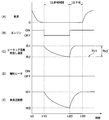
- FIG. 3 is a time chart when the radiation heater 4 is not operating continuously before the start of IS.
- the vehicle ECU 6 stops the engine by IS control at time t10.
- the case where the conditions for engine stop by IS control are satisfied means that the IS permission signal is transmitted from each ECU of the vehicle including the air conditioning ECU 7.
- the radiation heater 4 has stopped operating from time t0.
- the occupant's thermal sensation gradually decreases from the thermal sensation W1 before the engine is stopped as the blowout temperature of the air conditioner 2 decreases.
- the occupant's thermal sensation has decreased to a thermal sensation W2 at which the occupant feels a certain cold.
- the air conditioning ECU 7 stores a timer time from when the engine is stopped by IS control until the passenger feels a certain degree of cold. This timer time may be set in advance by an experiment or the like, or may be set as appropriate based on the vehicle interior temperature and the blowing temperature.
- an IS release signal is transmitted from the air conditioning ECU 7 to the vehicle ECU 6 at time t20. Then, as shown in FIG. 3B, the vehicle ECU 6 restarts the engine at time t20. As shown in FIG. 3A, the vehicle is maintained in a stopped state, and the vehicle speed is zero until time t30 when the vehicle starts running after time t20.
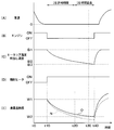
- FIG. 4 is a time chart in the case where the radiation heater 4 is continuously operated before the IS starts.
- the time chart shown in FIG. 3 and the time chart shown in FIG. 4 are the outside air temperature, the vehicle thermal load (ie, TAO: required blowing temperature), and the engine warm-up state (ie, engine coolant temperature).
- TAO required blowing temperature
- the engine warm-up state ie, engine coolant temperature.
- the air-conditioning ECU 7 may set “IS permission time” or “IS time extension” regardless of conditions such as outside air temperature, vehicle heat load, engine warm-up state, or the like. .
- the IS permission time from time t10 to time t20 shown in FIG. 3 and the IS permission time from time t10 to time t20 shown in FIG. 4 have the same length.
- FIG. 4 (A) when the vehicle speed becomes 0 or close to 0 from time t0 to time t10 and a predetermined condition for stopping the engine by IS control is satisfied, FIG. 4 (B) As shown, the vehicle ECU 6 stops the engine by IS control at time t10.
- the radiant heater 4 has been operating continuously from time t0 and is giving radiant heat to the occupant.
- the solid line M in FIG. 4 (E) indicates the thermal sensation of the occupant when the radiant heater 4 continues to operate before the start of IS.
- a broken line N in FIG. 4E indicates the thermal sensation of the occupant when the radiant heater 4 continues to stop operating before the start of IS.
- the occupant's thermal feeling W0 indicated by the solid line M feels warmer than the occupant's thermal feeling W1 indicated by the broken line N. Therefore, after time t10, the occupant's thermal sensation indicated by the solid line M gradually decreases with a decrease in the blowout temperature of the air conditioner 2, but feels warmer than the occupant's thermal sensation indicated by the broken line N. It has become. Therefore, the occupant's thermal sensation indicated by the solid line M becomes a thermal sensation W2 at which the occupant feels a certain cold at time t40 when a certain time has elapsed from time t20.
- the air conditioning ECU 7 When the radiant heater 4 is operating continuously before the start of the IS, the air conditioning ECU 7 extends the time from the time t20 to the time t40 in addition to the normal timer time from the time t10 to the time t20. When the extended timer time elapses at time t40, the air conditioning ECU 7 transmits an IS release signal to the vehicle ECU 6. Then, as shown in FIG. 4B, the vehicle ECU 6 restarts the engine at time t40.
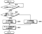
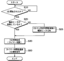
- step S10 the air conditioning ECU 7 determines whether or not the vehicle ECU 6 has stopped the engine by IS control. Note that control information is transferred between the air conditioning ECU 7 and the vehicle ECU 6 via an in-vehicle network such as CAN (Controller Area Network). The air conditioning ECU 7 repeats the process when the engine is not stopped by the IS control.
- CAN Controller Area Network
- step S20 When the air conditioning ECU 7 determines that the engine has been stopped by IS control, the process proceeds to step S20.
- step S20 the air conditioning ECU 7 functions as a determination unit and determines whether or not the radiation heater 4 is operating.
- the air conditioning ECU 7 monitors the drive control of the radiation heater 4 performed by the heater ECU 8. Therefore, if the air conditioning ECU 7 determines that the radiation heater 4 is operating, the process proceeds to step S30.
- step S30 the air conditioning ECU 7 functions as a time extension unit, and sets the time during which the engine stop by IS control can be continued to a timer time that is extended from the normal timer time.
- the timer time extended with respect to the normal timer time is referred to as the extended timer time.
- This extended timer time is obtained in advance by experiments or the like until the occupant feels a certain degree of cold after the engine is stopped by IS control when the radiation heater 4 is operating. It is remembered. Further, the extended timer time may be set as appropriate based on the passenger compartment temperature and the outlet temperature.
- the extended timer time is a time obtained by adding “IS permission time” and “IS time extension” shown in the time chart of FIG. 4 and corresponds to the time from time t10 to time t40.
- step S20 determines in step S20 that the radiation heater 4 is not operating. If the air conditioning ECU 7 determines in step S20 that the radiation heater 4 is not operating, the process proceeds to step S40.
- step S40 the air conditioning ECU 7 sets the normal timer time as the time during which the engine stop by IS control can be continued.
- the normal timer time is obtained in advance through experiments or the like until the occupant feels a certain cold after the engine is stopped by IS control when the radiation heater 4 is stopped. It is stored in the air conditioning ECU 7. Further, the normal timer time may be appropriately set based on the vehicle interior temperature and the blowout temperature.
- the normal timer time is the time indicated as “IS permission time” in the time charts of FIG. 3 and FIG. 4 and corresponds to the time from time t10 to time t20.
- step S50 the air conditioning ECU 7 transmits an IS release signal to the vehicle ECU 6 when the extended timer time set in step S30 or the normal timer time set in step S40 has elapsed.
- the IS cancellation signal is transmitted from the air conditioning ECU 7, the vehicle ECU 6 cancels the engine stop by the IS control and restarts the engine.
- the air conditioning ECU 7 of the first embodiment described above has the following operational effects.
- the air conditioning ECU 7 operates the radiant heater 4 from the time when the radiant heater 4 is not in operation with respect to the time from when the engine is stopped by IS control until the engine stop release signal is transmitted. It is configured to lengthen the time when you are. The time when the radiant heater 4 is not operating and the time when the radiant heater 4 is operating are compared under the same conditions such as the outside air temperature, the vehicle thermal load, and the engine warm-up state. Is the case. However, the air conditioning ECU 7 may set a normal timer time or an extended timer time regardless of conditions such as the outside air temperature, the vehicle heat load, the engine warm-up state, or the like.
- the air conditioning ECU 7 relates to the time from when the engine is stopped by IS control to when the engine stop release signal is transmitted, to the time when the radiation heater 4 is operating from the time when the radiation heater 4 is not operating. It can be lengthened. Therefore, the air conditioning ECU 7 can extend the time of IS, thereby improving the fuel consumption of the vehicle and reducing exhaust gas.
- the air conditioning ECU 7 performs the IS control when the temperature of the engine cooling water is relatively low, the decrease in the passenger's thermal feeling due to the low blowing temperature of the air conditioner 2 is compensated by the radiant heat of the radiant heater 4. Therefore, it is possible to extend the IS time.
- the air conditioning ECU 7 sets the timer time when the radiation heater 4 is operating longer than the timer time when the radiation heater 4 is not operating. Note that the timer time when the radiant heater 4 is not operating and the timer time when the radiant heater 4 is operating are under the same conditions such as the outside air temperature, the vehicle thermal load, and the engine warm-up state. It is a thing when comparing by. However, the air conditioning ECU 7 may set the timer time regardless of conditions such as the outside air temperature, the vehicle thermal load, the engine warm-up state, or the like.
- the air conditioning ECU 7 transmits an engine stop cancellation signal based on the timer time elapsed from the start of the IS. Therefore, the control program executed by the air conditioning ECU 7 can be simplified.
- the radiation heater 4 is provided in the position which can warm the place including the place where the blowing of FOOT of the air conditioner 2 warms a passenger
- the air conditioning ECU 7 includes a determination unit that functions in step 20 and a time extension unit that functions in step 30.
- the determination unit determines whether or not the radiation heater 4 is operating.
- the time extension unit determines the time from when the engine is stopped by IS control to when the radiation heater 4 is activated, when the radiation heater 4 is not activated. Longer than the time.
- Modification 1 Modification 1 of the above-described first embodiment will be described. This modification 1 is different from the first embodiment in the determination criteria used when the air conditioning ECU 7 transmits an engine stop cancellation signal, and is otherwise the same as the first embodiment. Therefore, in the description of the first modification, only parts different from the first embodiment will be described.
- the air conditioning ECU 7 stores a heater core temperature or a blowout temperature at which the occupant feels a certain cold in response to the operation or non-operation of the radiation heater 4.
- the heater core temperature or the blowing temperature may be obtained in advance through experiments or the like, or may be appropriately set based on the vehicle interior temperature or the like.
- the heater core temperature or the blowing temperature at which the passenger feels a certain cold when the radiant heater 4 is not operating is shown as a temperature threshold Th1.
- the heater core temperature or the blowing temperature at which the occupant feels a certain cold when the radiation heater 4 is operating is shown as the temperature threshold Th2.
- the air conditioning ECU 7 of Modification 1 sets the temperature threshold Th2 when the radiation heater 4 is operating during IS lower than the temperature threshold Th1 when the radiation heater 4 is not operating during IS. This is because, when the radiant heater 4 is operating during IS, the decrease in the passenger's thermal feeling due to the decrease in the blowing temperature of the air conditioner 2 is compensated by the radiant heat of the radiant heater 4.
- the heater core temperature or the blowing temperature gradually decreases from B1 after time t10.
- the air conditioning ECU 7 transmits an IS release signal to the vehicle ECU 6 when the heater core temperature or the blowing temperature becomes equal to or lower than the temperature threshold Th1 at time t20. Thereby, vehicle ECU6 restarts an engine.
- the air conditioning ECU 7 sets the temperature threshold value Th2 lower than the temperature threshold value Th1 shown in FIG. Therefore, the air conditioning ECU 7 transmits an IS release signal to the vehicle ECU 6 when the heater core temperature or the blow-off temperature becomes equal to or lower than the temperature threshold Th2 at time t40 after time t20. Thereby, vehicle ECU6 restarts an engine.
- the air conditioning ECU 7 sets the temperature threshold Th2 when the radiation heater 4 is operating lower than the temperature threshold Th1 when the radiation heater 4 is not operating.
- the temperature threshold value Th1 when the radiant heater 4 is not operating and the temperature threshold value Th2 when the radiant heater 4 is operated are under the same conditions such as the outside air temperature, the vehicle thermal load, and the engine warm-up state. It is a thing when comparing by.
- the air conditioning ECU 7 may set the temperature threshold regardless of conditions such as the outside air temperature, the vehicle thermal load, the engine warm-up state, or the like.
- the radiation heater 4 is less than the time when the radiation heater 4 is not operating. It is possible to lengthen the time when operating. Moreover, in the modification 1, a passenger
- Modification 2 Modification 2 of the first embodiment described above will be described.
- This modification 2 is also a modification of the first embodiment with respect to the determination criteria used when the air conditioning ECU 7 transmits an engine stop cancellation signal.
- the radiation heater 4 is activated or deactivated.
- a temperature difference such that the occupant feels a certain cold is stored in the air conditioning ECU 7.
- the temperature difference of the heater core temperature or the temperature difference of the blowing temperature may be set in advance by experiments or the like, or may be set as appropriate based on the vehicle interior temperature or the like.
- the air conditioning ECU 7 of Modification 2 sets the temperature difference threshold Th4 when the radiation heater 4 is operating during IS higher than the temperature difference threshold Th3 when the radiation heater 4 is not operating during IS. This is because, when the radiant heater 4 is operating during IS, the decrease in the passenger's thermal feeling due to the decrease in the blowing temperature of the air conditioner 2 is compensated by the radiant heat of the radiant heater 4.
- FIG. 3 (C) shows a case where the radiation heater 4 is not continuously operated before the IS starts.
- the difference between the heater core temperature or blowing temperature B1 at time t10 and the heater core temperature or blowing temperature B2 at time t20 is equal to or greater than the temperature difference threshold Th3.
- the air conditioning ECU 7 transmits an IS release signal to the vehicle ECU 6 at time t20. Thereby, vehicle ECU6 restarts an engine.
- FIG. 4C shows a case where the radiant heater 4 is continuously operated before the IS starts.
- the difference between the heater core temperature or blowing temperature B1 at time t10 and the heater core temperature or blowing temperature B3 at time t40 is equal to or greater than the temperature difference threshold Th4.
- the air conditioning ECU 7 transmits an IS release signal to the vehicle ECU 6 at time t40. Thereby, vehicle ECU6 restarts an engine.
- the air conditioning ECU 7 sets the temperature difference threshold Th4 when the radiation heater 4 is operating larger than the temperature difference threshold Th3 when the radiation heater 4 is not operating. It should be noted that the temperature difference threshold Th3 when the radiant heater 4 is not operating and the temperature difference threshold Th4 when the radiant heater 4 is operating have the same outside air temperature, vehicle heat load, engine warm-up state, and the like. It is a thing when comparing under conditions. However, the air-conditioning ECU 7 may set the temperature difference threshold regardless of conditions such as the outside air temperature, the vehicle thermal load, the engine warm-up state, or the like.
- the radiant heater 4 is less than the time when the radiant heater 4 is not in operation with respect to the time from when the engine is stopped by IS control until the engine stop release signal is transmitted. It is possible to lengthen the time when operating. Moreover, in the modification 2, a passenger
- IS control is performed by one or both of the vehicle ECU 6 and the air conditioning ECU 7 that constitute the IS control unit 10 shown in FIG.
- vehicle ECU6 and air-conditioning ECU7 may be comprised integrally, and may be comprised separately.
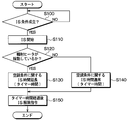
- step S100 the IS control unit 10 determines whether or not a predetermined condition for stopping the engine by IS control is satisfied, such as the vehicle speed becomes 0 or close to 0.
- a predetermined condition for stopping the engine by IS control is satisfied, such as the vehicle speed becomes 0 or close to 0.
- the vehicle speed for example, whether the vehicle interior temperature is higher than a predetermined room temperature threshold, whether the engine coolant temperature is higher than a predetermined water temperature threshold, or the battery voltage is a predetermined voltage value. Whether it is the above or not.
- the IS control unit 10 repeats the process of step S100 when any of the conditions for IS control is not satisfied. On the other hand, when all the conditions for IS control are satisfied, the IS control unit 10 proceeds to step S110. In step S110, the IS control unit 10 stops the engine and starts IS.
- step S120 the IS control unit 10 determines whether or not the radiation heater 4 is operating. If the IS control unit 10 determines that the radiation heater 4 is operating, the process proceeds to step S130.
- step S130 the IS control unit 10 sets a time during which the engine can be stopped by the IS control as an extended timer time for the air conditioning condition for continuing the IS.
- step S120 determines in step S120 that the radiant heater 4 is not operating. If the IS controller 10 determines in step S120 that the radiant heater 4 is not operating, the process proceeds to step S140.
- step S140 the IS control unit 10 sets a normal timer time as a time during which the engine can be stopped by the IS control with respect to the air conditioning condition for continuing the IS.
- step S150 when the extended timer time set in step S130 or the normal timer time set in step S140 has elapsed, the IS control unit 10 releases the engine stop by IS control and restarts the engine. .
- the IS control is performed by one or both of the vehicle ECU 6 and the air conditioning ECU 7 that constitute the IS control unit 10.
- the IS control unit 10 makes the time when the radiation heater 4 is operating longer than the time when the radiation heater 4 is not operating, with respect to the time from when the engine is stopped by IS control to releasing the engine stop.
- the time when the radiant heater 4 is not operating and the time when the radiant heater 4 is operating are compared under the same conditions such as the outside air temperature, the vehicle thermal load, and the engine warm-up state. Is the case.
- the IS control unit 10 may set a normal timer time or an extended timer time regardless of conditions such as the outside air temperature, the vehicle heat load, the engine warm-up state, or the like.
- the vehicle control system 1 can extend the time of IS, the fuel consumption of the vehicle can be improved and the exhaust gas can be reduced. Further, the vehicle control system 1 can extend the IS time even when the IS is performed at a relatively low temperature of the engine coolant.
- a third embodiment will be described.
- the air conditioning ECU 7 transmits an engine stop permission signal or release signal based on the air conditioning requirements to the vehicle ECU 6 and the vehicle ECU 6 stops and restarts the engine.
- the IS control described below can also be performed by the IS control unit 10 configured by one or both of the vehicle ECU 6 and the air conditioning ECU 7 as in the description of the second embodiment.
- the flowchart in FIG. 7 shows a process performed by the air conditioning ECU 7 when the vehicle ECU 6 stops the engine by IS control. This process may be performed at predetermined time intervals during engine operation, or before vehicle ECU 6 stops the engine by IS control.
- step S200 the air conditioning ECU 7 determines whether or not the radiation heater 4 is operating. If the air conditioning ECU 7 determines that the radiation heater 4 is operating, the process proceeds to step S210.
- the air conditioning ECU 7 sets the room temperature threshold value of the vehicle interior temperature or the water temperature threshold value of the cooling water temperature for permitting the engine stop by IS control to a value lower than the normal value.
- the room temperature threshold and the water temperature threshold which are lower than the normal values, are such that the passenger does not feel a certain cold when the engine is stopped by IS control when the radiation heater 4 is operating. It is obtained in advance by experiments or the like and stored in the air conditioning ECU 7.
- step S200 determines in step S200 that the radiant heater 4 is not operating. the process proceeds to step S220.
- step S220 the air conditioning ECU 7 sets the room temperature threshold value of the passenger compartment temperature or the water temperature threshold value of the cooling water temperature for permitting the engine stop by IS control to be a normal value.
- the room temperature threshold and the water temperature threshold which are normal values, are set in advance through experiments or the like so that the occupant does not feel a constant cold when the engine is stopped by IS control when the radiation heater 4 is not operating. It is obtained and stored in the air conditioning ECU 7.
- step S230 the air conditioning ECU 7 determines whether the vehicle interior temperature is higher than the room temperature threshold set in step S210 or step S220, or whether the engine coolant temperature is higher than the water temperature threshold. judge.
- the air conditioning ECU 7 transmits an IS permission signal to the vehicle ECU 6.
- the vehicle ECU 6 stops the engine when the vehicle speed is 0 or close to 0 and other IS conditions are satisfied.
- the air conditioning ECU 7 transmits an IS prohibition signal to the vehicle ECU 6. In this case, the vehicle ECU 6 continues to operate the engine even when the vehicle speed is 0 or close to 0 and other IS conditions are satisfied.
- the air conditioning ECU 7 relates to the engine stop condition by IS control, and the room temperature when the radiant heater 4 is operating is higher than the room temperature threshold or the water temperature threshold when the radiant heater 4 is not operating.
- Set the threshold or water temperature threshold to a low value.
- the room temperature threshold value or water temperature threshold value when the radiant heater 4 is not operating and the room temperature threshold value or water temperature threshold value when the radiant heater 4 is operated are the outside air temperature, the vehicle thermal load, and the engine warm-up state. And so on when compared under the same conditions.
- the air conditioning ECU 7 may set the room temperature threshold value or the water temperature threshold value regardless of conditions such as the outside air temperature, the vehicle heat load, the engine warm-up state, or the like. This air conditioning ECU 7 can improve the fuel efficiency of the vehicle and reduce the exhaust gas because the conditions under which the IS can be implemented are expanded.
- FIG. 8 (A) when the vehicle speed becomes 0 or close to 0 from time t0 to time t10 and a predetermined condition for stopping the engine by IS control is satisfied, FIG. 8 (B) As shown, the vehicle ECU 6 stops the engine by IS control at time t10.
- the radiant heater 4 is not operated from time t0 to time t10 before the start of IS.
- the radiation heater 4 operates in response to the engine stop.
- “the radiant heater 4 operates in response to the engine stop” means that the radiant heater 4 operates simultaneously with the engine stop and that the radiant heater 4 has a time difference of several ⁇ s to several seconds from the engine stop. It includes operating on.
- the solid line O in FIG. 8 (E) indicates the thermal sensation of the occupant when the radiant heater 4 operates in response to the engine stop.
- a broken line N in FIG. 8 (E) indicates the thermal sensation of the occupant when the radiant heater 4 continues to stop operating from before the IS starts to after the IS starts.
- the radiant heater 4 When the radiant heater 4 operates in response to the engine stop, the occupant is warmed by the radiant heat of the radiant heater 4. Therefore, after the time t10, the occupant's thermal sensation indicated by the solid line O gradually decreases as the blowout temperature of the air conditioner 2 decreases, but feels warmer than the occupant's thermal sensation indicated by the broken line N. It has become. Therefore, the occupant's thermal sensation indicated by the solid line O becomes a thermal sensation W2 to the extent that the occupant feels a certain cold at time t40 when a certain time has elapsed from time t20.
- the air conditioning ECU 7 sets an extended timer time.
- the extended timer time is a timer time extended with respect to the normal timer time, and specifically, “IS permission time” and “IS time extension” shown in the time chart of FIG. Is the time added.
- the air conditioning ECU 7 transmits an IS release signal to the vehicle ECU 6. Then, as shown in FIG. 8B, the vehicle ECU 6 restarts the engine at time t40.
- step S10 the air conditioning ECU 7 determines whether or not the vehicle ECU 6 has stopped the engine by IS control.
- the process proceeds to step S20.
- step S20 the air conditioning ECU 7 determines whether or not the radiation heater 4 is operating. If the air conditioning ECU 7 determines that the radiation heater 4 is not operating when the engine is stopped by IS control, the process proceeds to step S25.
- step S25 the air conditioning ECU 7 outputs to the heater ECU 8 an automatic operation signal for operating the radiation heater 4 in response to the engine stop by IS control.
- the heater ECU 8 operates the radiation heater 4 when the automatic operation signal is transmitted. Note that the air conditioning ECU 7 may operate the radiation heater 4 by directly transmitting an automatic operation signal to the radiation heater 4.
- step S25 the air conditioning ECU 7 moves the process to step S30.
- step S20 if the air conditioning ECU 7 determines that the radiation heater 4 is operating, the process proceeds to step S30.
- step S30 the air conditioning ECU 7 sets a time during which the engine can be stopped by the IS control as an extended timer time.
- step S50 the air conditioning ECU 7 transmits an IS release signal to the vehicle ECU 6 when the extended timer time set in step S30 has elapsed.
- the air conditioning ECU 7 generates an automatic operation signal for operating the radiation heater 4 in response to the engine stop when the engine is stopped by IS control while the radiation heater 4 is not operating. Output.
- the air conditioning ECU 7 automatically operates the radiant heater 4 to maintain the thermal sensation of the passenger. Therefore, the air conditioning ECU 7 can extend the IS time.
- FIG. 10 (A) when the vehicle speed becomes 0 or close to 0 from time t0 to time t10 and a predetermined condition for stopping the engine by IS control is satisfied, FIG. 10 (B) As shown, the vehicle ECU 6 stops the engine by IS control at time t10.
- the radiant heater 4 is not operated from time t0 before the IS start to time t15 after the IS start. After a certain time has elapsed since the engine was stopped by IS control at time t10, the radiation heater 4 starts operating at time t15.
- the predetermined time is the time from when the engine is stopped until the heater core temperature and the blow-out temperature reach predetermined temperatures, which are obtained in advance through experiments or the like and stored in the air conditioning ECU 7.
- the solid line P in FIG. 10 (E) shows the thermal sensation of the occupant when the radiation heater 4 starts to operate after a certain time has elapsed since the engine stopped.
- a broken line N in FIG. 10E indicates the thermal sensation of the occupant when the radiation heater 4 continues to stop operating from before the IS starts to after the IS starts.
- the radiant heater 4 starts operating at a time t15 when a certain time has elapsed since the engine stopped, the passenger is warmed by the radiant heat of the radiant heater 4 after the time t15. Therefore, after time t10, the occupant's thermal sensation indicated by the solid line P gradually decreases as the blow-off temperature of the air conditioner 2 decreases, but it feels warmer than the occupant's thermal sensation indicated by the broken line N. It has become. Therefore, the occupant's thermal sensation indicated by the solid line P becomes a thermal sensation W2 at which the occupant feels a certain cold at time t40 when a certain time has elapsed from time t20.
- the air conditioning ECU 7 sets an extended timer time.
- the air conditioning ECU 7 transmits an IS release signal to the vehicle ECU 6. Then, as shown in FIG. 10B, the vehicle ECU 6 restarts the engine at time t40.
- step S10 the air conditioning ECU 7 determines whether or not the vehicle ECU 6 has stopped the engine by IS control.
- the process proceeds to step S20.
- step S20 the air conditioning ECU 7 determines whether or not the radiation heater 4 is operating. If the air conditioning ECU 7 determines that the radiation heater 4 is not operating when the engine is stopped by IS control, the process proceeds to step S26.
- step S26 the air conditioning ECU 7 outputs an automatic operation signal for operating the radiation heater 4 to the heater ECU 8 after a predetermined time has elapsed since the engine stop by IS control.
- the heater ECU 8 operates the radiation heater 4 when the automatic operation signal is transmitted. Note that the air conditioning ECU 7 may operate the radiation heater 4 by directly transmitting an automatic operation signal to the radiation heater 4.
- step S26 the air conditioning ECU 7 proceeds to step S30.
- step S20 if the air conditioning ECU 7 determines that the radiation heater 4 is operating, the process proceeds to step S30.
- step S30 the air conditioning ECU 7 sets a time during which the engine can be stopped by the IS control as an extended timer time.
- step S50 the air conditioning ECU 7 transmits an IS release signal to the vehicle ECU 6 when the extended timer time set in step S30 has elapsed.
- the air conditioning ECU 7 automatically activates the radiation heater 4 after a certain time has elapsed since the engine stopped when the engine is stopped by IS control while the radiation heater 4 is not operating. Is output.
- the vehicle control system 1 of the sixth embodiment includes an operation permission switch 11 for an occupant to operate.
- the operation permission switch 11 allows the occupant to select whether or not to allow the radiation heater 4 to operate in accordance with the automatic operation signal output from the air conditioning ECU 7 described in the fourth and fifth embodiments.
- the operation signal of the operation permission switch 11 is input to either the heater ECU 8 or the air conditioning ECU 7.
- the operation signal of the operation permission switch 11 may be configured to be directly input to the radiation heater 4.
- the operation permission switch 11 and the heater operation unit 9 may be configured integrally.
- step S10 the air conditioning ECU 7 determines whether or not the vehicle ECU 6 has stopped the engine by IS control.
- the process proceeds to step S20.
- step S20 the air conditioning ECU 7 determines whether or not the radiation heater 4 is operating. If the air conditioning ECU 7 determines that the radiation heater 4 is not operating when the engine is stopped by the IS control, the process proceeds to step S21.
- step S21 the air conditioning ECU 7 detects an operation signal of the operation permission switch 11 operated by the occupant. In other words, the air conditioning ECU 7 determines whether or not the operation permission switch 11 permits the radiation heater 4 to automatically operate in response to the automatic operation signal.
- step S40 the air conditioning ECU 7 sets the normal timer time as the time during which the engine stop by IS control can be continued, and the process proceeds to step S50.
- step S25 if the air conditioning ECU 7 determines that the radiation heater 4 is automatically permitted to operate by the operation signal of the operation permission switch 11, the process proceeds to step S25.
- step S25 the air conditioning ECU 7 outputs to the heater ECU 8 an automatic operation signal for operating the radiation heater 4 in response to the engine stop by IS control.
- the heater ECU 8 operates the radiation heater 4 when the automatic operation signal is transmitted. Note that the air conditioning ECU 7 may operate the radiation heater 4 by directly transmitting an automatic operation signal to the radiation heater 4.
- step S25 the air conditioning ECU 7 moves the process to step S30.
- step S30 the air conditioning ECU 7 sets a time during which the engine can be stopped by the IS control as an extended timer time.
- step S50 the air conditioning ECU 7 transmits an IS release signal to the vehicle ECU 6 when the extended timer time set in step S30 or the normal timer time set in step S40 has elapsed.
- the air conditioning ECU 7 is configured such that when the radiation heater 4 is not in operation, the engine is stopped by IS control and the operation of the radiation heater 4 is permitted by the operation permission switch 11. The radiation heater 4 is operated. On the other hand, the air conditioning ECU 7 does not operate the radiation heater 4 when the engine is stopped by the IS control in a state where the radiation heater 4 is not operated and the operation permission switch 11 does not permit the operation of the radiation heater 4.
- FIG. 14 is a time chart relating to vehicle control by the vehicle control system 1 of the seventh embodiment.
- the vehicle ECU 6 starts the engine at time t50. After time t50, the engine continues to operate. Thereafter, when the vehicle speed becomes 0 or close to 0 and a condition for stopping the engine by IS control is satisfied, the vehicle ECU 6 stops the engine by IS control at time t70.
- the heater core temperature and the blow-off temperature of the air conditioner 2 gradually increase when the operation of the engine is started at time t50 and gradually decrease after the engine is stopped at time t70.
- the radiation heater 4 operates simultaneously with the start of operation of the engine at time t50.
- the radiant heater 4 increases the surface temperature in a short time, and increases the occupant's thermal feeling by giving radiant heat to the occupant even when the temperature of the engine coolant immediately after the start of engine operation is low. Is possible.
- the air conditioning ECU 7 or the heater ECU 8 maintains the surface temperature of the radiant heater 4 within a predetermined temperature range.
- the radiant heater 4 is energized so that
- the predetermined temperature range refers to a temperature at which the occupant hardly feels the thermal feeling due to the radiant heat of the radiant heater 4.
- the surface temperature of the radiant heater 4 is maintained at about 50 ° C., for example.
- the air conditioning ECU 7 Even when the occupant does not operate the heater operation switch at time t60, when a predetermined time has elapsed since the engine start, the air conditioning ECU 7 generates a surface temperature switching signal for switching the surface temperature of the radiant heater 4 within a predetermined temperature range. You may transmit to heater ECU8.
- the air conditioning ECU 7 determines that the engine coolant temperature, the heater core temperature, or the blowout temperature has sufficiently increased after the engine is started, and thus the surface temperature switching signal described above. May be transmitted to the heater ECU 8.
- the air conditioning ECU 7 automatically activates the radiation heater 4 so that the surface temperature of the radiation heater 4 can sufficiently warm the passenger. Is output to the heater ECU 8. Thereby, the heater ECU 8 increases the surface temperature of the radiant heater 4.
- the air conditioning ECU 7 may directly transmit an automatic operation signal to the radiation heater 4 to increase the surface temperature of the radiation heater 4.
- the temperature of the radiant heater 4 is the temperature H3 when the energization is stopped before starting the engine, and reaches a temperature H1 that gives a sufficient thermal feeling to the passenger in a short time from the time t50. To rise.
- the temperature of the radiant heater 4 is maintained at a temperature H2 that does not give the passenger a feeling of heat.
- the surface temperature of the radiant heater 4 is increased by an automatic operation signal output from the air conditioning ECU 7.
- the temperature of the radiant heater 4 rises to a temperature H1 that gives the passenger a sense of heat. To do.
- the alternate long and short dash line R in FIG. 14C indicates the temperature of the radiant heater 4 when power to the radiant heater 4 is stopped at time t60.
- the temperature of the radiant heater 4 is lowered to the temperature H3 when the energization is stopped. Therefore, when the radiant heater 4 is activated by the automatic operation signal output from the air conditioning ECU 7 at time t70, the temperature of the radiant heater 4 rises to a temperature H1 that gives a sense of heat to the occupant at time t90 when a certain time has elapsed from time t80. .
- the temperature of the radiant heater 4 is maintained at a temperature H2 that does not give the passenger a feeling of heat before the engine is stopped by IS control, the temperature of the radiant heater 4 is sufficient for the occupant after the engine is stopped. It takes a short time until the temperature H1 rises to give a warm feeling.
- the temperature of the radiant heater 4 is lowered to the temperature H3 when the energization is stopped before the engine is stopped by IS control, the temperature of the radiant heater 4 is increased to the predetermined temperature H1 after the engine is stopped. It takes a long time.
- the occupant's thermal sensation gradually rises after starting the engine at time t50, and becomes thermal sensation W1 at which the user feels sufficient warmth at time t60. Even after the time t60, even if the radiant heater 4 does not give a sense of heat to the occupant, the heater core temperature and the blowing temperature of the air conditioner 2 are sufficiently high, so that the occupant's sense of heat is sufficiently warm. The feeling of thermal feeling W1 is maintained.
- the solid line S is maintained at a temperature H2 at which the temperature of the radiant heater 4 does not give the occupant a thermal sensation before the engine is stopped by IS control. It shows the warmth of the occupant. As shown by the solid line S, the thermal sensation of the occupant gradually decreases from the thermal sensation W1 before the engine is stopped, as the blowing temperature of the air conditioner 2 decreases. At time t90 after the time t80 has elapsed, the thermal sensation of the occupant has decreased to a thermal sensation W2 to the extent that the occupant feels a certain degree of cold.
- the alternate long and short dash line T in FIG. 14 (D) shows the thermal sensation of the passenger when the temperature of the radiant heater 4 has decreased to the temperature H3 when the energization is stopped before the engine is stopped by IS control. Yes.
- the alternate long and short dash line T the occupant's thermal sensation is reduced to a thermal sensation W2 at which the occupant feels a certain degree of cold at a time earlier than the time t90.
- a broken line U in FIG. 14D indicates the thermal sensation of the occupant when the operation of the radiant heater 4 is stopped after time t70. As shown by the broken line U, the occupant's thermal sensation decreases to a thermal sensation W2 at which the occupant feels a certain cold at a time earlier than the time t80.
- the air conditioning ECU 7 operates so that the surface temperature of the radiation heater 4 is maintained within a predetermined temperature range even when the operation of the radiation heater 4 is stopped during the operation of the engine. 4 is energized.
- FIG. 15 shows processing performed by the air conditioning ECU 7 of the eighth embodiment during IS.
- step S10 the air conditioning ECU 7 determines whether or not the vehicle ECU 6 has stopped the engine by IS control.
- the process proceeds to step S20.
- step S20 the air conditioning ECU 7 determines whether or not the radiation heater 4 is operating. If the air conditioning ECU 7 determines that the radiation heater 4 is operating when the engine is stopped by IS control, the process proceeds to step S27.
- step S27 the air conditioning ECU 7 stops the FOOT blowing of the air conditioner 2 or reduces the FOOT blowing amount. This process may be performed simultaneously with the engine stop by IS control, or may be performed after a predetermined time has elapsed since the engine stop.
- the term “after a predetermined time” as used herein refers to the time from when the engine is stopped until the heater core temperature or the blow-out temperature of the air conditioner 2 becomes equal to or lower than a certain temperature, which is obtained in advance through experiments and stored in the air conditioning ECU 7. It is.
- the air conditioning ECU 7 determines that the FOOT blowing amount when the heater core temperature or the blowing temperature of the air conditioner 2 becomes equal to or lower than a certain temperature, or when the temperature drop from the engine stop becomes equal to or larger than a certain value. May be reduced or stopped.
- step S27 the air conditioning ECU 7 shifts the processing to step S30.
- step S30 the air conditioning ECU 7 sets a time during which the engine can be stopped by the IS control as an extended timer time.
- step S20 determines in step S20 that the radiation heater 4 is not operating. If the air conditioning ECU 7 determines in step S20 that the radiation heater 4 is not operating, the process proceeds to step S40.
- step S40 the air conditioning ECU 7 sets the normal timer time as the time during which the engine stop by IS control can be continued.
- step S50 the air conditioning ECU 7 transmits an IS release signal to the vehicle ECU 6 when the extended timer time set in step S30 or the normal timer time set in step S40 has elapsed.
- the air conditioning ECU 7 stops the FOOT blowing of the air conditioner 2 or the FOOT blowing when the engine is stopped by the IS control and the radiation heater 4 is operating. Reduce the amount.
- the air conditioning ECU 7 can suppress a decrease in the thermal sensation of the passenger at the time of IS and can extend the time of IS.
- FIG. 16 shows the processing performed by the air conditioning ECU 7 of the ninth embodiment during IS.
- step S10 the air conditioning ECU 7 determines whether or not the vehicle ECU 6 has stopped the engine by IS control.
- the process proceeds to step S20.
- step S20 the air conditioning ECU 7 determines whether or not the radiation heater 4 is operating. If the air conditioning ECU 7 determines that the radiation heater 4 is operating when the engine is stopped by IS control, the process proceeds to step S27.
- step S25 if the air conditioning ECU 7 determines that the radiation heater 4 is not operating when the engine is stopped by IS control, the process proceeds to step S25.
- step S25 the air conditioning ECU 7 outputs to the heater ECU 8 an automatic operation signal for operating the radiation heater 4 in response to the engine stop by IS control.
- the heater ECU 8 operates the radiation heater 4 when the automatic operation signal is transmitted. Note that the air conditioning ECU 7 may operate the radiation heater 4 by directly transmitting an automatic operation signal to the radiation heater 4.
- step S25 the air conditioning ECU 7 moves the process to step S27.
- step S27 the air conditioning ECU 7 stops the FOOT blowing of the air conditioner 2 or reduces the FOOT blowing amount.
- step S27 the air conditioning ECU 7 shifts the processing to step S30.
- step S30 the air conditioning ECU 7 sets a time during which the engine can be stopped by the IS control as an extended timer time.
- step S50 the air conditioning ECU 7 transmits an IS release signal to the vehicle ECU 6 when the extended timer time set in step S30 has elapsed.
- the ninth embodiment described above has the same operational effects as the eighth embodiment.
- the air conditioning ECU 7 has been described as transmitting the IS permission signal and the IS release signal to the vehicle ECU 6.
- the IS control is performed by one or both of the vehicle ECU 6 and the air conditioning ECU 7. You may do.
- the air conditioning ECU 7 has been described as outputting an automatic operation signal for operating the radiation heater 4 to the heater ECU 8. However, in other embodiments, one of the air conditioning ECU 7 and the heater ECU 8 is used. Or you may drive-control the radiation heater 4 by both.
- an air-conditioning control apparatus heats the vehicle interior provided with the radiation heater which heats a passenger
- the air conditioning control device transmits an engine stop cancellation signal when a predetermined timer time has elapsed since the engine stop by IS control, and from the timer time when the radiation heater is not operating.
- the timer time when the radiant heater is operating is set longer.
- the air conditioning control device transmits an engine stop cancellation signal by IS control when the heater core temperature or the blow-off temperature of the air conditioning device is equal to or lower than a predetermined temperature threshold.
- the air conditioning control device sets the temperature threshold when the radiation heater is operating lower than the temperature threshold when the radiation heater is not operating.
- the air conditioning control device can improve passenger comfort by performing fine temperature control.
- the air-conditioning control device determines whether the engine is stopped by IS control when the temperature difference that has decreased from the heater core temperature or the blowing temperature of the air-conditioning device when the engine is stopped is equal to or greater than a predetermined temperature difference threshold value. A release signal is transmitted. The air conditioning control device sets the temperature difference threshold when the radiation heater is operating larger than the temperature difference threshold when the radiation heater is not operating.
- the air conditioning control device can improve passenger comfort by performing fine temperature control.
- an automatic operation signal for operating the radiation heater is output in response to the engine stop.
- the air conditioning control device can extend the IS time.
- an automatic operation signal for operating the radiation heater is output after a certain time has elapsed since the engine was stopped.
- the vehicle is provided with an operation permission switch that allows the occupant to select whether or not to permit the operation of the radiation heater by the automatic operation signal of the air conditioning control device.
- the air conditioning control device operates the radiation heater by an automatic operation signal.
- the air conditioning control device does not operate the radiation heater when the engine is stopped by IS control in a state where the radiation heater is not operated and the operation of the radiation heater is not permitted by the operation permission switch.
- the air conditioning control device is configured so that the surface temperature of the radiant heater is maintained within a predetermined temperature range when heating of the occupant by the radiant heat of the radiant heater is stopped during the operation of the engine. Energize the radiant heater.
- the time for the surface temperature of the radiant heater to rise can be shortened.
- the air-conditioning control device stops or blows off the air-conditioning device to the feet and lower legs when the engine is stopped by the idling stop control and the radiation heater is operating. Reduce the amount.
- the convection of the air at the foot of the occupant is suppressed. Therefore, the occupant's lower leg can be effectively warmed by the radiant heater.
- the air conditioning control device sets the IS condition so as to permit engine stop when the vehicle interior temperature is higher than a predetermined room temperature threshold or when the engine cooling water is higher than a predetermined water temperature threshold.
- the air conditioning control device is configured to set the room temperature threshold or the water temperature threshold when the radiation heater is operating lower than the room temperature threshold or the water temperature threshold when the radiation heater is not operating in the setting related to the IS condition. Has been.
- the air conditioning control device sets the room temperature threshold value or water temperature threshold value when the radiation heater is operating lower than the room temperature threshold value or water temperature threshold value when the radiation heater is not operating, with respect to the engine stop condition by IS control. It is possible. Therefore, in this air conditioning control device, the conditions under which IS can be implemented are expanded, so that the fuel efficiency of the vehicle can be improved and the exhaust gas can be reduced.
- the air conditioning control device includes a determination unit and a time extension unit.
- the determination unit determines whether or not the radiation heater is operating.
- the time extending unit is the time from when the engine is stopped by the idling stop control until the engine stop cancellation signal is transmitted. Make it longer than the time.
- the vehicle control system includes an air conditioner, a radiation heater, and an IS control unit.
- the air conditioner heats the interior of the vehicle using engine cooling water.
- the radiation heater raises the surface temperature by energization and heats the occupant by radiant heat.
- the IS control unit is configured to make the time when the radiation heater is operating longer than the time when the radiation heater is not operating, with respect to the time from the engine stop by IS control to releasing the engine stop. ing.
- the vehicle control system can extend the time of IS, the fuel consumption of the vehicle can be improved and the exhaust gas can be reduced.
- the vehicle control system can extend the IS time even when the IS is performed at a relatively low temperature of the engine coolant.
- the IS control unit is configured by one or both of an air conditioning control device and a vehicle control device.
- the radiant heater is provided at a position where a place including a place where the occupant is warmed by blowing to the lower leg of the air conditioner can be heated by radiant heat.
Landscapes
- Engineering & Computer Science (AREA)
- Chemical & Material Sciences (AREA)
- Combustion & Propulsion (AREA)
- Mechanical Engineering (AREA)
- General Engineering & Computer Science (AREA)
- Physics & Mathematics (AREA)
- Thermal Sciences (AREA)
- Air-Conditioning For Vehicles (AREA)
- Control Of Vehicle Engines Or Engines For Specific Uses (AREA)
Abstract
空調制御装置(7)は、通電により乗員を暖房する輻射ヒータ(4)を備える車両の車室内をエンジン冷却水を用いて暖房する空調装置(2)を制御すると共に、アイドリングストップ制御によるエンジン停止の解除信号を発信するものである。空調制御装置(7)は、アイドリングストップ制御によるエンジン停止からエンジン停止の解除信号を発信するまでの時間に関し、輻射ヒータ(4)が作動していないときの時間より、輻射ヒータ(4)が作動しているときの時間を長くするように構成されている。
Description
本出願は、2016年4月25日に出願された日本特許出願番号2016-87246号に基づくもので、ここにその記載内容が参照により組み入れられる。
本開示は、空調制御装置および車両制御システムに関するものである。
従来、エンジンの冷却水を用いて車両の車室内を暖房する空調装置を制御する空調制御装置が知られている。
特許文献1に記載の空調制御装置は、車室内を暖房する制御を行っているときに、車両のエンジンがアイドリングストップ(以下「IS」という)制御により停止すると、空調装置が備えているエアミックスドアの開度を、温風の量を高める側へ補正する。これにより、この空調制御装置は、IS時に乗員の温熱感を維持できる時間を延長している。
発明者らの詳細な検討の結果、特許文献1に記載の空調制御装置には、次の課題が見出された。即ち、特許文献1に記載の空調制御装置は、IS制御によりエンジンが停止する前から、エアミックスドアが温風の量を高める側に最大の開度となっている場合、乗員の温熱感を維持できる時間を延長することはできない。
また、この空調制御装置は、IS時に空調装置が備えているヒートコアの熱量を早期に消費するので、空調装置の吹出し温度が早期に低下することが考えられる。その場合、IS時に乗員の温熱感を維持できる時間が短くなる。また、空調装置の吹出し温度または吹出し温度の低下幅に基づいてエンジン停止を解除するIS制御を行う車両では、空調装置の吹出し温度が早期に低下すると、ISの時間が短くなるおそれがある。これにより、燃費が悪化し、排ガスの排出量が増加することが懸念される。
本開示は、IS時の乗員の温熱感低下を抑制すると共に、IS時間を延長することの可能な空調制御装置および車両制御システムを提供することを目的とする。
本開示の1つの観点によれば、空調制御装置は、通電により乗員を暖房する輻射ヒータを備える車両の車室内をエンジン冷却水を用いて暖房する空調装置を制御すると共に、IS制御によるエンジン停止の解除信号を発信するものである。この空調制御装置は、IS制御によるエンジン停止からエンジン停止の解除信号を発信するまでの時間に関し、輻射ヒータが作動していないときの時間より、輻射ヒータが作動しているときの時間を長くするように構成されている。
これによれば、IS制御によりエンジンが停止するとエンジン冷却水の循環が停止し、ヒータコアの温度低下と共に空調装置の吹出し温度が低下する。しかし、輻射ヒータが作動しているときは、空調装置の吹出し温度の低下に伴う乗員の温熱感の低下が輻射ヒータの輻射熱により補填される。そのため、空調制御装置は、IS制御によるエンジン停止からエンジン停止の解除信号を発信するまでの時間に関し、輻射ヒータが作動していないときの時間より、輻射ヒータが作動しているときの時間を長くすることが可能である。したがって、この空調制御装置は、ISの時間を延長できるので、車両の燃費を向上し、排ガスを低減できる。
また、空調制御装置は、エンジン冷却水の温度が比較的低温状態でIS制御を行う場合でも、空調装置の吹出し温度が低いことによる乗員の温熱感の低下が輻射ヒータの輻射熱により補填されるので、ISの時間を延長することが可能である。
また、別の観点によれば、空調制御装置は、車室内温度が所定の室温閾値より高いとき、またはエンジン冷却水が所定の水温閾値より高いときにエンジン停止を許可するIS条件に関し、輻射ヒータが作動していないときの室温閾値または水温閾値より、輻射ヒータが作動しているときの室温閾値または水温閾値を低い値に設定するように構成されている。
これによれば、IS制御によりエンジンを停止する際、車室内温度が低い場合、または空調装置の吹出し温度が低い場合でも、輻射ヒータが作動しているときは乗員の温熱感の低下が輻射ヒータの輻射熱により補填される。そのため、空調制御装置は、IS制御によるエンジン停止の条件に関し、輻射ヒータが作動していないときの室温閾値または水温閾値より、輻射ヒータが作動しているときの室温閾値または水温閾値を低く設定することが可能である。したがって、この空調制御装置は、ISを実施可能な条件が拡がるので、車両の燃費を向上し、排ガスを低減できる。
さらに別の観点によれば、車両制御システムは、空調装置、輻射ヒータおよびIS制御部を備える。空調装置は、車両の車室内をエンジン冷却水を用いて暖房する。輻射ヒータは、通電により表面温度を上昇させ輻射熱によって乗員を暖房する。IS制御部は、IS制御によるエンジン停止からエンジン停止を解除するまでの時間に関し、輻射ヒータが作動していないときの時間より、輻射ヒータが作動しているときの時間を長くするように構成されている。
これによれば、車両制御システムは、ISの時間を延長できるので、車両の燃費を向上し、排ガスを低減できる。また、車両制御システムは、エンジン冷却水の温度が比較的低温状態でISを行う場合でも、ISの時間を延長することが可能である。
なお、IS制御部は、空調制御装置および車両制御装置の一方または両方により構成されるものである。
以下、本開示の実施形態について、図を参照しつつ説明する。なお、以下の各実施形態相互において、互いに同一もしくは均等である部分には、同一符号を付して説明を行う。
(第1実施形態)
第1実施形態について図面を参照しつつ説明する。図1に示すように、本実施形態の車両制御システム1が搭載される車両は、車室内の空気の温度または湿度などを調整する空調装置2を備えている。
第1実施形態について図面を参照しつつ説明する。図1に示すように、本実施形態の車両制御システム1が搭載される車両は、車室内の空気の温度または湿度などを調整する空調装置2を備えている。
空調装置2は、暖房用熱交換器としての図示していないヒータコアを通過する空気を、エンジン冷却水との熱交換により加熱して車室内に吹き出し、車室内を暖房するものである。また、空調装置2は、冷房用熱交換器としての図示していない蒸発器を通過する空気を、冷媒との熱交換により冷却して車室内に吹き出し、車室内を冷房および除湿することが可能なものであってもよい。
図2では、空調装置2のFOOTの吹出口から車室内に吹き出される空気を模式的に矢印Fにて示している。空調装置2は、暖房を行う際、FOOTの吹出口から吹き出される空気により、乗員の下腿3および足元を含む箇所を暖めることが可能である。
また、この車両は、車室内に、薄い板状に形成された輻射ヒータ4を備えている。輻射ヒータ4は、車両に搭載されたバッテリまたは発電機などの電源から給電されて発熱する電気的なヒータである。輻射ヒータ4は、赤外線を発する図示していない発熱部への通電を行うことで表面温度を上昇させ、輻射熱を放射する。発熱部は、例えば、銅とスズとの合金(即ち、Cu-Sn)、銀、スズ、ステンレス鋼、ニッケル、ニクロムなどの金属およびこれらを含む合金を用いて構成される。
輻射ヒータ4は、主にその表面に対して垂直な方向へ向けて輻射熱を放射し、その方向に位置する対象物を暖める。輻射ヒータ4は、乗員に対して即効的に暖かさを提供するための装置として利用することができる。この輻射ヒータ4は、乗員が座席に座った際に想定される通常姿勢の乗員の下腿3に対向する位置に設置され、主に乗員の下腿3およびその周辺に輻射熱を放射する。輻射ヒータ4は、例えば、ハンドルを支持するためのステアリングコラム5の下側に設置される。
図2では、輻射ヒータ4が放射する輻射熱を模式的に矢印Rにて示している。本実施形態では、空調装置2が空調風により乗員を暖める場所と、輻射ヒータ4が輻射熱により乗員を暖める場所とが重なっている。すなわち、輻射ヒータ4は、空調装置2が空調風により乗員を暖める場所を含む場所を、輻射熱により暖めることが可能である。
図1に示すように、本実施形態の車両制御システム1は、車両に搭載されたエンジンを駆動制御する車両制御装置6、空調装置2を駆動制御する空調制御装置7、および、輻射ヒータ4を駆動制御するヒータ制御装置8などを備えている。以下の説明において、車両制御装置6を、車両ECU6と呼ぶ。空調制御装置7を、空調ECU7と呼ぶ。ヒータ制御装置8を、ヒータECU8と呼ぶ。なお、車両ECU6、空調ECU7およびヒータECU8はいずれも、CPU、ROM、RAMなどから構成されるマイクロコンピュータとその周辺機器とを備えている。これらのECUは、ROMまたはRAMに格納されたプログラムをCPUが実行することで、各種の演算処理や制御処理を行うように構成されたものである。CPUは制御部に相当するものである。また、ROMおよびRAMは非遷移的実体的記憶媒体であり、記憶部に相当するものである。
なお、車両ECU6、空調ECU7およびヒータECU8は、一体に構成されたものでもよく、または別体で構成されたものでもよい。
車両の車室内には、ヒータ操作部9が設けられている。ヒータ操作部9は、輻射ヒータ4の作動と非作動の切り替えを乗員が選択できるヒータ操作スイッチを有するものである。ヒータECU8は、ヒータ操作部9が有するヒータ操作スイッチから伝送される信号に基づき、輻射ヒータ4を駆動制御する。
また、ヒータECU8は、乗員が輻射ヒータ4に触れた際、輻射ヒータ4の表面温度を下げる制御を行うことが可能なものでもよい。
空調ECU7は、空調装置2を駆動制御すると共に、ヒータECU8が行う輻射ヒータ4の駆動制御を監視する。また、空調ECU7は、車両ECU6に対し、IS制御によるエンジン停止を許可するためのIS許可信号、および、そのエンジン停止後にエンジンを再始動させるためのIS解除信号を伝送する。
空調ECU7には、車室内温度を計測する内気温センサ14から出力される信号、および、空調装置2の吹出口から車室内に吹き出される空調風の温度を計測する吹出温センサ13から出力される信号などが入力される。また、車両ECU6には、エンジン冷却水の温度を計測する冷却水センサ12から出力される信号が入力される。空調ECU7には、車両ECU6を経由して、エンジン冷却水の温度情報を取得することが可能である。なお、冷却水センサ12から出力される信号が、直接、空調ECU7に入力されるように構成されていてもよい。
空調ECU7によるIS許可信号は、例えば車室内温度が所定の室温閾値より高いとき、または、エンジン冷却水の温度が所定の水温閾値より高いときに、空調ECU7から車両ECU6に伝送される。また、空調ECU7によるIS解除信号は、IS制御によるエンジン停止から所定のタイマー時間が経過したときに、空調ECU7から車両ECU6に伝送される。
車両ECU6は、IS許可信号およびIS解除信号に基づき、エンジンのIS制御を行う。すなわち、車両ECU6と空調ECU7とは、エンジンのIS制御を実行するためのIS制御部10を構成する。
なお、車両ECU6には、空調ECU7の他にも、車両の各機能を制御するための図示していない複数のECUから、それぞれのIS許可条件に基づくIS許可信号、および、IS解除条件に基づくIS解除信号が伝送される。車両ECU6は、それらのIS許可信号およびIS解除信号に基づいて、エンジンのIS制御を行うこともある。
次に、本実施形態の車両制御システム1によるIS制御について説明する。
図3は、IS開始前から継続して輻射ヒータ4が作動していない場合のタイムチャートである。
図3(A)に示すように、時刻t0から時刻t10にかけて車速が0または0に近くなり、且つ、IS制御によるエンジン停止を行うための条件が成立した場合、図3(B)に示すように、車両ECU6は時刻t10でIS制御によりエンジンを停止する。なお、IS制御によるエンジン停止のための条件が成立した場合とは、空調ECU7を含む車両の各ECUからIS許可信号が伝送されたことをいう。
IS制御によりエンジンが停止すると、エンジン冷却水の循環が停止する。そのため、図3(C)に示すように、時刻t10以降、空調装置2のヒータコアの温度がB1から次第に低下すると共に、吹出し温度もそれに伴って低下する。
図3(D)に示すように、輻射ヒータ4は、時刻t0から継続して作動を停止している。
図3(E)に示すように、乗員の温熱感は、空調装置2の吹出し温度の低下に伴い、エンジン停止前の温熱感W1から次第に低下する。時刻t20で、乗員の温熱感は、乗員が一定の寒さを感じる程度の温熱感W2まで低下している。
空調ECU7には、IS制御によりエンジンが停止してから、乗員が一定の寒さを感じる程度になるまでのタイマー時間が記憶されている。このタイマー時間は、実験などにより予め設定されたものでもよく、または、車室内温度および吹出し温度に基づいて適宜設定されるものであってもよい。
時刻t10から所定のタイマー時間が経過すると、時刻t20で空調ECU7からIS解除信号が車両ECU6に伝送される。すると、図3(B)に示すように、車両ECU6は時刻t20でエンジンを再始動させる。なお、図3(A)に示すように、車両は停止した状態が維持されており、時刻t20以降も車両が走行を開始する時刻t30まで車速は0である。
ISが解除されエンジンが再始動すると、空調装置2をエンジン冷却水が循環する。そのため、図3(C)に示すように、時刻t20以降、ヒータコアの温度がB2から次第に上昇すると共に、空調装置2の吹出し温度もそれに伴って上昇する。これにより、図3(E)に示すように、時刻t20以降、乗員の温熱感はW2から次第に上昇する。
図3(A)に示すように、時刻t30でブレーキが解除されてアクセルが踏み込まれ、車両が走行を開始すると車速が上昇する。
これに対し、図4は、IS開始前から継続して輻射ヒータ4が作動している場合のタイムチャートである。なお、図3で示したタイムチャートと、図4で示したタイムチャートとは、外気温、車両熱負荷(即ち、TAO:必要吹出し温度)、およびエンジン暖機状態(即ち、エンジン冷却水温度)などが同一の条件下で比較したものである。ただし、空調ECU7は、外気温、車両熱負荷、エンジン暖機状態などの条件とは無関係に、または、関係性を持って、「IS許可時間」や「IS時間延長」を設定するものとしてよい。
また、図3で示した時刻t10から時刻t20までのIS許可時間と、図4で示した時刻t10から時刻t20までのIS許可時間とは同一の長さである。
図4(A)に示すように、時刻t0から時刻t10にかけて車速が0または0に近くなり、且つ、IS制御によるエンジン停止を行うための所定の条件が成立した場合、図4(B)に示すように、車両ECU6は時刻t10でIS制御によりエンジンを停止する。
図4(C)に示すように、時刻t10以降、空調装置2のヒータコアの温度がB1から次第に低下すると共に、吹出し温度もそれに伴って低下する。
図4(D)に示すように、輻射ヒータ4は、時刻t0から継続して作動しており、乗員に対し輻射熱を与えている。
図4(E)の実線Mは、輻射ヒータ4がIS開始前から継続して作動している場合の乗員の温熱感を示している。図4(E)の破線Nは、輻射ヒータ4がIS開始前から継続して作動を停止している場合の乗員の温熱感を示している。
輻射ヒータ4がIS開始前から継続して作動している場合、輻射ヒータ4の輻射熱により乗員が暖められている。そのため、図4(E)の時刻t0から時刻t10において、実線Mで示した乗員の温熱感W0は、破線Nで示した乗員の温熱感W1よりも暖かさを感じるものとなっている。そのため、時刻t10以降、実線Mで示した乗員の温熱感は、空調装置2の吹出し温度の低下に伴って次第に低下するものの、破線Nで示した乗員の温熱感よりも暖かさを感じるものとなっている。したがって、実線Mで示した乗員の温熱感は、時刻t20から一定時間経過した時刻t40で、乗員が一定の寒さを感じる程度の温熱感W2になる。
輻射ヒータ4がIS開始前から継続して作動している場合、空調ECU7は、時刻t10から時刻t20までの通常のタイマー時間に加え、時刻t20から時刻t40までの時間を延長する。空調ECU7は、時刻t40でその延長したタイマー時間が経過すると、車両ECU6に対してIS解除信号を伝送する。すると、図4(B)に示すように、車両ECU6は時刻t40でエンジンを再始動させる。
時刻t40でエンジンが再始動すると、エンジン冷却水が空調装置2を循環する。そのため、図4(C)に示すように、時刻t40以降、ヒータコアの温度がB3から次第に上昇すると共に、空調装置2の吹出し温度もそれに伴って上昇する。これにより、図4(E)の実線Mに示すように、時刻t40以降、乗員の温熱感はW2から次第に上昇する。
図4(A)に示すように、時刻t40以降に車両が走行を開始すると車速が上昇する。
続いて、本実施形態の空調ECU7がIS時に行う処理について、図5のフローチャートを参照して説明する。
ステップS10で、空調ECU7は、車両ECU6がIS制御によるエンジン停止を行ったか否かを判定する。なお、空調ECU7と車両ECU6とは、例えばCAN(Controller Area Network)などの車載ネットワークにより制御情報が転送される。空調ECU7は、IS制御によるエンジン停止がされない場合、その処理を繰り返す。
空調ECU7は、IS制御によるエンジン停止が行われたことを判定すると、処理をステップS20に移行する。
ステップS20で、空調ECU7は、判定部として機能し、輻射ヒータ4が稼動しているか否かを判定する。空調ECU7は、ヒータECU8が行う輻射ヒータ4の駆動制御を監視している。そのため、空調ECU7は、輻射ヒータ4が稼動していると判定すると、処理をステップS30に移行する。
ステップS30で、空調ECU7は、時間延長部として機能し、IS制御によるエンジン停止を継続可能な時間を、通常のタイマー時間に対して延長したタイマー時間に設定する。以下の説明では、通常のタイマー時間に対して延長したタイマー時間を、延長タイマー時間ということとする。この延長タイマー時間は、輻射ヒータ4が作動している際に、IS制御によりエンジンが停止してから乗員が一定の寒さを感じる程度になるまでの時間が予め実験などで求められ、空調ECU7に記憶されている。また、延長タイマー時間は、車室内温度および吹出し温度に基づいて適宜設定されるものであってもよい。
なお、延長タイマー時間は、図4のタイムチャートに示した「IS許可時間」と「IS時間延長」とを加算した時間であり、時刻t10から時刻t40までの時間に相当するものである。
これに対し、ステップS20で、空調ECU7は、輻射ヒータ4が稼動していないと判定すると、処理をステップS40に移行する。
ステップS40で、空調ECU7は、IS制御によるエンジン停止を継続可能な時間を、通常のタイマー時間に設定する。
なお、通常のタイマー時間は、輻射ヒータ4が作動停止している際に、IS制御によりエンジンが停止してから乗員が一定の寒さを感じる程度になるまでの時間が予め実験などで求められ、空調ECU7に記憶されている。また、通常のタイマー時間は、車室内温度および吹出し温度に基づいて適宜設定されるものであってもよい。
なお、通常のタイマー時間は、図3および図4のタイムチャートで「IS許可時間」として示した時間であり、時刻t10から時刻t20までの時間に相当するものである。
続いて、ステップS50で、空調ECU7は、ステップS30で設定した延長タイマー時間、またはステップS40で設定した通常のタイマー時間が経過すると、車両ECU6に対し、IS解除信号を発信する。車両ECU6は、空調ECU7からIS解除信号が伝送されると、IS制御によるエンジン停止を解除し、エンジンを再始動する。
以上説明した第1実施形態の空調ECU7は、次の作用効果を奏する。
(1)第1実施形態では、空調ECU7は、IS制御によるエンジン停止からエンジン停止の解除信号を発信するまでの時間に関し、輻射ヒータ4が作動していないときの時間より、輻射ヒータ4が作動しているときの時間を長くするように構成されている。なお、上述の輻射ヒータ4が作動していないときの時間と、輻射ヒータ4が作動しているときの時間とは、外気温、車両熱負荷、エンジン暖機状態などが同一の条件下で比較した場合のものである。ただし、空調ECU7は、外気温、車両熱負荷、エンジン暖機状態などの条件とは無関係に、または、関係性を持って、通常のタイマー時間や延長タイマー時間を設定するものとしてよい。
これによれば、IS制御によりエンジンが停止するとき、空調装置2の吹出し温度の低下に伴う乗員の温熱感の低下が、輻射ヒータ4の輻射熱により補填される。そのため、空調ECU7は、IS制御によるエンジン停止からエンジン停止の解除信号を発信するまでの時間に関し、輻射ヒータ4が作動していないときの時間より、輻射ヒータ4が作動しているときの時間を長くすることが可能である。したがって、この空調ECU7は、ISの時間を延長できるので、車両の燃費を向上し、排ガスを低減できる。
また、空調ECU7は、エンジン冷却水の温度が比較的低温状態でIS制御を行う場合でも、空調装置2の吹出し温度が低いことによる乗員の温熱感の低下が輻射ヒータ4の輻射熱により補填されるので、ISの時間を延長することが可能である。
(2)第1実施形態では、空調ECU7は、輻射ヒータ4が作動していないときのタイマー時間より、輻射ヒータ4が作動しているときのタイマー時間を長く設定している。なお、上述の輻射ヒータ4が作動していないときのタイマー時間と、輻射ヒータ4が作動しているときのタイマー時間とは、外気温、車両熱負荷、エンジン暖機状態などが同一の条件下で比較した場合のものである。ただし、空調ECU7は、外気温、車両熱負荷、エンジン暖機状態などの条件とは無関係に、または、関係性を持って、タイマー時間を設定するものとしてよい。
これによれば、空調ECU7は、IS開始から経過したタイマー時間を判断基準として、エンジン停止の解除信号を発信する。したがって、空調ECU7が実行する制御プログラムを簡素なものにできる。
(3)第1実施形態では、輻射ヒータ4は、空調装置2のFOOTの吹出しが乗員を暖める場所を含む場所を輻射熱により暖めることの可能な位置に設けられる。
これによれば、IS時における空調装置2の吹出し温度の低下に伴う乗員の温熱感の低下を、輻射ヒータ4の輻射熱により補填できる。
(4)第1実施形態では、空調ECU7は、ステップ20において機能する判定部と、ステップ30において機能する時間延長部を備えているといえる。判定部は、輻射ヒータ4が作動しているか否かを判定する。時間延長部は、判定部により輻射ヒータ4が作動していると判定されたとき、IS制御によるエンジン停止からエンジン停止の解除信号を発信するまでの時間を、輻射ヒータ4が作動していないときの時間よりも長くする。
(変形例1)
上述した第1実施形態の変形例1について説明する。この変形例1は、第1実施形態に対し、空調ECU7がエンジン停止の解除信号を発信する際の判断基準を変更したものであり、その他については第1実施形態と同様である。そのため、変形例1の説明では、第1実施形態と異なる部分についてのみ説明する。
上述した第1実施形態の変形例1について説明する。この変形例1は、第1実施形態に対し、空調ECU7がエンジン停止の解除信号を発信する際の判断基準を変更したものであり、その他については第1実施形態と同様である。そのため、変形例1の説明では、第1実施形態と異なる部分についてのみ説明する。
変形例1では、輻射ヒータ4の作動または非作動に対応して、乗員が一定の寒さを感じる程度のヒータコア温度または吹出し温度が、空調ECU7に記憶されている。このヒータコア温度または吹出し温度は、予め実験などにより求められたものでもよく、または、車室内温度等に基づいて適宜設定されるものであってもよい。
図3(C)では、輻射ヒータ4が作動していないときに、乗員が一定の寒さを感じる程度のヒータコア温度または吹出し温度を、温度閾値Th1として示している。一方、図4(C)では、輻射ヒータ4が作動しているときに、乗員が一定の寒さを感じる程度のヒータコア温度または吹出し温度を、温度閾値Th2として示している。
変形例1の空調ECU7は、IS時に輻射ヒータ4が作動していないときの温度閾値Th1より、IS時に輻射ヒータ4が作動しているときの温度閾値Th2を低く設定している。これは、IS時に輻射ヒータ4が作動しているときには、空調装置2の吹出し温度の低下に伴う乗員の温熱感の低下が輻射ヒータ4の輻射熱により補填されるからである。
図3(C)に示すように、IS開始前から継続して輻射ヒータ4が作動していない場合、時刻t10以降、ヒータコア温度または吹出し温度は、B1から次第に低下する。空調ECU7は、時刻t20でヒータコア温度または吹出し温度が温度閾値Th1と同じかそれより低くなると、車両ECU6に対しIS解除信号を伝送する。これにより、車両ECU6は、エンジンを再始動させる。
これに対し、図4(C)に示すように、IS開始前から継続して輻射ヒータ4が作動している場合も、時刻t10以降、ヒータコア温度または吹出し温度は、B1から次第に低下する。この場合、上述したように、空調ECU7は、温度閾値Th2を図3(C)で示した温度閾値Th1よりも低く設定している。そのため、空調ECU7は、時刻t20を過ぎた時刻t40で、ヒータコア温度または吹出し温度が温度閾値Th2と同じかそれより低くなると、車両ECU6に対しIS解除信号を伝送する。これにより、車両ECU6は、エンジンを再始動させる。
以上説明した変形例1では、空調ECU7は、輻射ヒータ4が作動していないときの温度閾値Th1より、輻射ヒータ4が作動しているときの温度閾値Th2を低く設定する。なお、輻射ヒータ4が作動していないときの温度閾値Th1と、輻射ヒータ4が作動しているときの温度閾値Th2とは、外気温、車両熱負荷、エンジン暖機状態などが同一の条件下で比較した場合のものである。ただし、空調ECU7は、外気温、車両熱負荷、エンジン暖機状態などの条件とは無関係に、または、関係性を持って、温度閾値を設定するものとしてよい。
変形例1においても、第1実施形態と同様に、IS制御によるエンジン停止からエンジン停止の解除信号を発信するまでの時間に関し、輻射ヒータ4が作動していないときの時間より、輻射ヒータ4が作動しているときの時間を長くすることが可能である。また、変形例1では、IS時における空調装置2のヒータコア温度または吹出し温度から乗員の温熱感を推定できる。したがって、空調ECU7は、きめ細かい温度制御を行うことで、乗員の快適性を高めることが可能である。
(変形例2)
上述した第1実施形態の変形例2について説明する。この変形例2も、第1実施形態に対し、空調ECU7がエンジン停止の解除信号を発信する際の判断基準を変更したものである。
上述した第1実施形態の変形例2について説明する。この変形例2も、第1実施形態に対し、空調ECU7がエンジン停止の解除信号を発信する際の判断基準を変更したものである。
変形例2では、IS前のヒータコア温度または吹出し温度と、その温度から所定の温度幅で低下したときのヒータコア温度または吹出し温度との温度差に関し、輻射ヒータ4の作動または非作動に対応して乗員が一定の寒さを感じる程度の温度差が、空調ECU7に記憶されている。このヒータコア温度の温度差または吹出し温度の温度差は、実験などにより予め設定されたものでもよく、または、車室内温度等に基づいて適宜設定されるものであってもよい。
図3(C)では、輻射ヒータ4が作動していない場合において、IS前のヒータコア温度または吹出し温度と、乗員が一定の寒さを感じる程度のヒータコア温度または吹出し温度との温度差を、温度差閾値Th3として示している。一方、図4(C)では、輻射ヒータ4が作動している場合において、IS前のヒータコア温度または吹出し温度と、乗員が一定の寒さを感じる程度のヒータコア温度の温度差または吹出し温度の温度との温度差を、温度差閾値Th4として示している。
変形例2の空調ECU7は、IS時に輻射ヒータ4が作動していないときの温度差閾値Th3より、IS時に輻射ヒータ4が作動しているときの温度差閾値Th4を大きく設定している。これは、IS時に輻射ヒータ4が作動しているときには、空調装置2の吹出し温度の低下に伴う乗員の温熱感の低下が輻射ヒータ4の輻射熱により補填されるからである。
IS開始前から継続して輻射ヒータ4が作動していない場合を図3(C)に示す。その場合、時刻t10におけるヒータコア温度または吹出し温度B1と、時刻t20におけるヒータコア温度または吹出し温度B2との差が、温度差閾値Th3と同じかそれより大きくなる。このとき、空調ECU7は、時刻t20で、車両ECU6に対しIS解除信号を伝送する。これにより、車両ECU6は、エンジンを再始動させる。
これに対し、IS開始前から継続して輻射ヒータ4が作動している場合を図4(C)に示す。その場合、時刻t10におけるヒータコア温度または吹出し温度B1と、時刻t40におけるヒータコア温度または吹出し温度B3との差が、温度差閾値Th4と同じかそれより大きくなる。このとき、空調ECU7は、時刻t40で、車両ECU6に対しIS解除信号を伝送する。これにより、車両ECU6は、エンジンを再始動させる。
以上説明した変形例2では、空調ECU7は、輻射ヒータ4が作動していないときの温度差閾値Th3より、輻射ヒータ4が作動しているときの温度差閾値Th4を大きく設定する。なお、輻射ヒータ4が作動していないときの温度差閾値Th3と、輻射ヒータ4が作動しているときの温度差閾値Th4とは、外気温、車両熱負荷、エンジン暖機状態などが同一の条件下で比較した場合のものである。ただし、空調ECU7は、外気温、車両熱負荷、エンジン暖機状態などの条件とは無関係に、または、関係性を持って、温度差閾値を設定するものとしてよい。
変形例2においても、第1実施形態と同様に、IS制御によるエンジン停止からエンジン停止の解除信号を発信するまでの時間に関し、輻射ヒータ4が作動していないときの時間より、輻射ヒータ4が作動しているときの時間を長くすることが可能である。また、変形例2では、IS時における空調装置2のヒータコア温度の低下幅または吹出し温度の低下幅から乗員の温熱感を推定できる。したがって、空調ECU7は、きめ細かい温度制御を行うことで、乗員の快適性を高めることが可能である。
(第2実施形態)
第2実施形態について説明する。第2実施形態では、図2に示したIS制御部10を構成する車両ECU6および空調ECU7の一方または両方により、IS制御を行う。なお、車両ECU6と空調ECU7とは一体に構成されてもよく、または別体にて構成されてもよい。
第2実施形態について説明する。第2実施形態では、図2に示したIS制御部10を構成する車両ECU6および空調ECU7の一方または両方により、IS制御を行う。なお、車両ECU6と空調ECU7とは一体に構成されてもよく、または別体にて構成されてもよい。
第2実施形態のIS制御部10が行う処理について、図6のフローチャートを参照して説明する。
ステップS100で、IS制御部10は、車速が0または0に近くなる等、IS制御によるエンジン停止を行うための所定の条件が成立したか否かを判定する。この条件として、車速に関するものの他に、例えば車室内温度が所定の室温閾値より高か否か、エンジン冷却水の温度が所定の水温閾値より高いか否か、または、バッテリ電圧が所定の電圧値以上であるか否かなどがあげられる。
IS制御部10は、IS制御のための条件のいずれかが成立しない場合、ステップS100の処理を繰り返す。一方、IS制御部10は、IS制御のための全ての条件が成立した場合、処理をステップS110に移行する。ステップS110でIS制御部10は、エンジンを停止し、ISを開始する。
次に、ステップS120で、IS制御部10は、輻射ヒータ4が稼動しているか否かを判定する。IS制御部10は、輻射ヒータ4が稼動していると判定すると、処理をステップS130に移行する。
ステップS130で、IS制御部10は、IS継続のための空調条件に関し、IS制御によるエンジン停止を継続可能な時間を、延長タイマー時間に設定する。
これに対し、ステップS120で、IS制御部10は、輻射ヒータ4が稼動していないと判定すると、処理をステップS140に移行する。
ステップS140で、IS制御部10は、IS継続のための空調条件に関し、IS制御によるエンジン停止を継続可能な時間を、通常のタイマー時間に設定する。
続いて、ステップS150で、IS制御部10は、ステップS130で設定した延長タイマー時間、またはステップS140で設定した通常のタイマー時間が経過すると、IS制御によるエンジン停止を解除し、エンジンを再始動する。
以上説明した第2実施形態では、IS制御は、IS制御部10を構成する車両ECU6および空調ECU7の一方または両方により行われる。IS制御部10は、IS制御によるエンジン停止からエンジン停止を解除するまでの時間に関し、輻射ヒータ4が作動していないときの時間より、輻射ヒータ4が作動しているときの時間を長くする。なお、上述の輻射ヒータ4が作動していないときの時間と、輻射ヒータ4が作動しているときの時間とは、外気温、車両熱負荷、エンジン暖機状態などが同一の条件下で比較した場合のものである。ただし、IS制御部10は、外気温、車両熱負荷、エンジン暖機状態などの条件とは無関係に、または、関係性を持って、通常のタイマー時間や延長タイマー時間を設定するものとしてよい。
これによれば、車両制御システム1は、ISの時間を延長できるので、車両の燃費を向上し、排ガスを低減できる。また、車両制御システム1は、エンジン冷却水の温度が比較的低温状態でISを行う場合でも、ISの時間を延長することが可能である。
(第3実施形態)
第3実施形態について説明する。なお、以下の複数の実施形態の説明では、空調ECU7が空調要件に基づくエンジン停止の許可信号または解除信号を車両ECU6に伝送し、車両ECU6がエンジンの停止および再始動を行うものとして説明する。但し、以下に説明するIS制御は、上述した第2実施形態の説明と同様に、車両ECU6および空調ECU7の一方または両方により構成されるIS制御部10が行うことも可能である。
第3実施形態について説明する。なお、以下の複数の実施形態の説明では、空調ECU7が空調要件に基づくエンジン停止の許可信号または解除信号を車両ECU6に伝送し、車両ECU6がエンジンの停止および再始動を行うものとして説明する。但し、以下に説明するIS制御は、上述した第2実施形態の説明と同様に、車両ECU6および空調ECU7の一方または両方により構成されるIS制御部10が行うことも可能である。
図7のフローチャートは、車両ECU6がIS制御によりエンジンを停止する際に、空調ECU7が行う処理を示したものである。なお、この処理は、エンジン運転中に所定時間間隔ごとに行ってもよく、または、車両ECU6がIS制御によりエンジンを停止する前に行ってもよい。
まず、ステップS200で、空調ECU7は、輻射ヒータ4が稼動しているか否かを判定する。空調ECU7は、輻射ヒータ4が稼動していると判定すると、処理をステップS210に移行する。
輻射ヒータ4が作動しているときは、車室内温度が低いことによる乗員の温熱感の低下が輻射ヒータ4の輻射熱により補填される。また、輻射ヒータ4が作動しているときは、空調装置2の吹出し温度が低いことによる乗員の温熱感の低下が輻射ヒータ4の輻射熱により補填される。そのため、ステップS210で、空調ECU7は、IS制御によるエンジン停止を許可するための車室内温度の室温閾値または冷却水温度の水温閾値を、通常時の値よりも低い値に設定する。通常時の値よりも低い値である室温閾値および水温閾値は、輻射ヒータ4が作動している場合にIS制御によりエンジンが停止したときに乗員が一定の寒さを感じない程度の室温および水温が予め実験などで求められ、空調ECU7に記憶されている。
これに対し、ステップS200で、空調ECU7は、輻射ヒータ4が稼動していないと判定すると、処理をステップS220に移行する。
ステップS220で、空調ECU7は、IS制御によるエンジン停止を許可するための車室内温度の室温閾値または冷却水温度の水温閾値を、通常時の値とする。通常時の値である室温閾値および水温閾値は、輻射ヒータ4が作動していない場合にIS制御によりエンジンが停止したときに乗員が一定の寒さを感じない程度の室温および水温が予め実験などで求められ、空調ECU7に記憶されている。
続いて、ステップS230で、空調ECU7は、ステップS210またはステップS220で設定した室温閾値に対して車室内温度が高いか否か、または水温閾値に対してエンジンの冷却水温度が高いか否かを判定する。
室温閾値に対して車室内温度が高い場合、または、水温閾値に対してエンジンの冷却水温度が高い場合、空調ECU7はIS許可信号を車両ECU6に伝送する。この場合、車両ECU6は、車速が0または0に近くなり、且つ、その他のIS条件が成立すると、エンジンを停止する。
一方、室温閾値に対して車室内温度が低い場合、または、水温閾値に対してエンジンの冷却水温度が低い場合、空調ECU7はIS禁止信号を車両ECU6に伝送する。この場合、車両ECU6は、車速が0または0に近くなり、且つ、その他のIS条件が成立した場合でも、エンジンの運転を継続する。
以上説明した第3実施形態では、空調ECU7は、IS制御によるエンジン停止の条件に関し、輻射ヒータ4が作動していないときの室温閾値または水温閾値より、輻射ヒータ4が作動しているときの室温閾値または水温閾値を低い値に設定する。なお、上述の輻射ヒータ4が作動していないときの室温閾値または水温閾値と、輻射ヒータ4が作動しているときの室温閾値または水温閾値とは、外気温、車両熱負荷、エンジン暖機状態などが同一の条件下で比較した場合のものである。ただし、空調ECU7は、外気温、車両熱負荷、エンジン暖機状態などの条件とは無関係に、または、関係性を持って、室温閾値または水温閾値を設定するものとしてよい。この空調ECU7は、ISを実施可能な条件が拡がるので、車両の燃費を向上し、排ガスを低減できる。
(第4実施形態)
第4実施形態について説明する。以下、第4から第7実施形態は、IS開始前に輻射ヒータ4が作動していない場合にIS制御によるエンジン停止を行うときの処理に関するものである。
第4実施形態について説明する。以下、第4から第7実施形態は、IS開始前に輻射ヒータ4が作動していない場合にIS制御によるエンジン停止を行うときの処理に関するものである。
第4実施形態の車両制御システム1によるIS制御について、図8のタイムチャートを参照して説明する。
図8(A)に示すように、時刻t0から時刻t10にかけて車速が0または0に近くなり、且つ、IS制御によるエンジン停止を行うための所定の条件が成立した場合、図8(B)に示すように、車両ECU6は時刻t10でIS制御によりエンジンを停止する。
図8(C)に示すように、時刻t10以降、空調装置2のヒータコアの温度がB1から次第に低下すると共に、吹出し温度もそれに伴って低下する。
図8(D)に示すように、輻射ヒータ4は、IS開始前の時刻t0から時刻t10の間は作動していない。時刻t10で、輻射ヒータ4がエンジン停止に対応して作動する。なお、ここで、「輻射ヒータ4がエンジン停止に対応して作動する」とは、輻射ヒータ4がエンジン停止と同時に作動することに加え、輻射ヒータ4がエンジン停止から数μ秒から数秒の時間差で作動することを含むものである。
図8(E)の実線Oは、輻射ヒータ4がエンジン停止に対応して作動した場合の乗員の温熱感を示している。図8(E)の破線Nは、輻射ヒータ4がIS開始前からIS開始後も継続して作動を停止している場合の乗員の温熱感を示している。
輻射ヒータ4がエンジン停止に対応して作動した場合、輻射ヒータ4の輻射熱により乗員が暖められる。そのため、時刻t10以降、実線Oで示した乗員の温熱感は、空調装置2の吹出し温度の低下に伴って次第に低下するものの、破線Nで示した乗員の温熱感よりも暖かさを感じるものとなっている。したがって、実線Oで示した乗員の温熱感は、時刻t20から一定時間経過した時刻t40で、乗員が一定の寒さを感じる程度の温熱感W2になる。
輻射ヒータ4がエンジン停止に対応して作動した場合、空調ECU7は、延長タイマー時間を設定する。上述したように、延長タイマー時間とは、通常のタイマー時間に対して延長したタイマー時間であり、具体的には、図8のタイムチャートに示した「IS許可時間」と「IS時間延長」とを加算した時間である。空調ECU7は、時刻t40でその延長タイマー時間が経過すると、車両ECU6に対してIS解除信号を伝送する。すると、図8(B)に示すように、車両ECU6は時刻t40でエンジンを再始動させる。
時刻t40でエンジンが再始動すると、エンジン冷却水が空調装置2を循環する。そのため、図8(C)に示すように、時刻t40以降、ヒータコアの温度がB3から次第に上昇すると共に、空調装置2の吹出し温度もそれに伴って上昇する。これにより、図8(E)の実線Oに示すように、時刻t40以降、乗員の温熱感はW2から次第に上昇する。乗員の温熱感上昇後は輻射ヒータの出力を低下または輻射ヒータを再び停止させてもよい。
図8(A)に示すように、時刻t40以降にアクセルが踏み込まれ、車両が走行を開始すると車速が上昇する。
続いて、第4実施形態の空調ECU7がIS時に行う処理について、図9のフローチャートを参照して説明する。
ステップS10で、空調ECU7は、車両ECU6がIS制御によるエンジン停止を行ったか否かを判定する。空調ECU7は、IS制御によるエンジン停止が行われたことを判定すると、処理をステップS20に移行する。
ステップS20で、空調ECU7は、輻射ヒータ4が稼動しているか否かを判定する。空調ECU7は、IS制御によるエンジン停止が行われたときに輻射ヒータ4が稼動していないと判定すると、処理をステップS25に移行する。
ステップS25で、空調ECU7は、IS制御によるエンジン停止に対応して輻射ヒータ4を作動するための自動作動信号をヒータECU8に出力する。ヒータECU8は、その自動作動信号が伝送されると、輻射ヒータ4を作動させる。なお、空調ECU7は、輻射ヒータ4に自動作動信号を直接伝送し、輻射ヒータ4を作動させてもよい。
ステップS25の後、空調ECU7は、処理をステップS30に移行する。
また、ステップS20で、空調ECU7は、輻射ヒータ4が稼動していると判定した場合、処理をステップS30に移行する。
ステップS30で、空調ECU7は、IS制御によるエンジン停止を継続可能な時間を、延長タイマー時間に設定する。
続いて、ステップS50で、空調ECU7は、ステップS30で設定した延長タイマー時間が経過すると、車両ECU6に対し、IS解除信号を伝送する。
以上説明した第4実施形態では、空調ECU7は、輻射ヒータ4が作動していない状態でIS制御によりエンジンが停止した場合、エンジン停止に対応して輻射ヒータ4を作動するための自動作動信号を出力する。
これによれば、IS時に空調装置2の吹出し温度が低下しても、空調ECU7が輻射ヒータ4を自動的に作動させることで、乗員の温熱感が維持される。そのため、空調ECU7は、ISの時間を延長できる。
(第5実施形態)
第5実施形態について説明する。第5実施形態の車両制御システム1によるIS制御を図10のタイムチャートを参照して説明する。
第5実施形態について説明する。第5実施形態の車両制御システム1によるIS制御を図10のタイムチャートを参照して説明する。
図10(A)に示すように、時刻t0から時刻t10にかけて車速が0または0に近くなり、且つ、IS制御によるエンジン停止を行うための所定の条件が成立した場合、図10(B)に示すように、車両ECU6は時刻t10でIS制御によりエンジンを停止する。
図10(C)に示すように、時刻t10以降、空調装置2のヒータコアの温度がB1から次第に低下すると共に、吹出し温度もそれに伴って低下する。
図10(D)に示すように、輻射ヒータ4は、IS開始前の時刻t0からIS開始後の時刻t15まで作動していない。時刻t10でIS制御によりエンジンが停止してから一定時間経過した後、時刻t15で輻射ヒータ4は作動を開始する。なお、この一定時間は、エンジンが停止してからヒータコア温度および吹出し温度が所定の温度になるまでの時間が予め実験などにより求められ、空調ECU7に記憶されたものである。
図10(E)の実線Pは、輻射ヒータ4がエンジン停止から一定時間経過した後に作動を開始した場合の乗員の温熱感を示している。図10(E)の破線Nは、輻射ヒータ4がIS開始前からIS開始後も継続して作動を停止している場合の乗員の温熱感を示している。
輻射ヒータ4がエンジン停止から一定時間経過した時刻t15に作動を開始した場合、その時刻t15以降、輻射ヒータ4の輻射熱により乗員が暖められる。そのため、時刻t10以降、実線Pで示した乗員の温熱感は、空調装置2の吹出し温度の低下に伴って次第に低下するものの、破線Nで示した乗員の温熱感よりも暖かさを感じるものとなっている。したがって、実線Pで示した乗員の温熱感は、時刻t20から一定時間経過した時刻t40で、乗員が一定の寒さを感じる程度の温熱感W2になる。
輻射ヒータ4がエンジン停止から一定時間経過した後に作動を開始した場合、空調ECU7は延長タイマー時間を設定する。空調ECU7は、時刻t40でその延長したタイマー時間が経過すると、車両ECU6に対してIS解除信号を伝送する。すると、図10(B)に示すように、車両ECU6は時刻t40でエンジンを再始動させる。
続いて、第5実施形態の空調ECU7がIS時に行う処理について、図11のフローチャートを参照して説明する。
ステップS10で、空調ECU7は、車両ECU6がIS制御によるエンジン停止を行ったか否かを判定する。空調ECU7は、IS制御によるエンジン停止が行われたことを判定すると、処理をステップS20に移行する。
ステップS20で、空調ECU7は、輻射ヒータ4が稼動しているか否かを判定する。空調ECU7は、IS制御によるエンジン停止が行われたときに輻射ヒータ4が稼動していないと判定すると、処理をステップS26に移行する。
ステップS26で、空調ECU7は、IS制御によるエンジン停止から一定時間経過後に、輻射ヒータ4を作動するための自動作動信号をヒータECU8に出力する。ヒータECU8は、その自動作動信号が伝送されると、輻射ヒータ4を作動させる。なお、空調ECU7は、輻射ヒータ4に自動作動信号を直接伝送し、輻射ヒータ4を作動させてもよい。
ステップS26の後、空調ECU7は、処理をステップS30に移行する。
また、ステップS20で、空調ECU7は、輻射ヒータ4が稼動していると判定した場合、処理をステップS30に移行する。
ステップS30で、空調ECU7は、IS制御によるエンジン停止を継続可能な時間を、延長タイマー時間に設定する。
続いて、ステップS50で、空調ECU7は、ステップS30で設定した延長タイマー時間が経過すると、車両ECU6に対し、IS解除信号を伝送する。
以上説明した第5実施形態では、空調ECU7は、輻射ヒータ4が作動していない状態でIS制御によりエンジンが停止した場合、エンジン停止から一定時間経過後に輻射ヒータ4を作動するための自動作動信号を出力する。
これによれば、エンジン停止直後のヒータコアの温度が高い間は、輻射ヒータ4の作動を停止していることで、車両の消費電力を低減することが可能である。
(第6実施形態)
第6実施形態について説明する。
第6実施形態について説明する。
図12に示すように、第6実施形態の車両制御システム1は、乗員が操作するための作動許可スイッチ11を備えている。作動許可スイッチ11は、上記第4、第5実施形態で説明した空調ECU7が出力する自動作動信号に応じて輻射ヒータ4が作動することを許可するか否かを乗員が選択できるものである。作動許可スイッチ11の動作信号は、ヒータECU8または空調ECU7のいずれかに入力される。或いは、作動許可スイッチ11の動作信号は、輻射ヒータ4に直接入力されるように構成してもよい。なお、作動許可スイッチ11とヒータ操作部9とを一体に構成してもよい。
第6実施形態の空調ECU7がIS時に行う処理について、図13のフローチャートを参照して説明する。
ステップS10で、空調ECU7は、車両ECU6がIS制御によるエンジン停止を行ったか否かを判定する。空調ECU7は、IS制御によるエンジン停止が行われたことを判定すると、処理をステップS20に移行する。
ステップS20で、空調ECU7は、輻射ヒータ4が稼動しているか否かを判定する。空調ECU7は、IS制御によるエンジン停止が行われたときに輻射ヒータ4が稼動していないと判定すると、処理をステップS21に移行する。
ステップS21で、空調ECU7は、乗員が操作する作動許可スイッチ11の動作信号を検出する。即ち、空調ECU7は、自動作動信号に応じて輻射ヒータ4が自動的に作動することに関し、作動許可スイッチ11により許可されているか否かを判定する。
空調ECU7は、輻射ヒータ4が自動的に作動することが許可されていないと判定すると、処理をステップS40に移行する。ステップS40で、空調ECU7は、IS制御によるエンジン停止を継続可能な時間を通常のタイマー時間に設定し、処理をステップS50に移行する。
一方、空調ECU7は、作動許可スイッチ11の動作信号により、輻射ヒータ4が自動的に作動することが許可されていると判定すると、処理をステップS25に移行する。
ステップS25で、空調ECU7は、IS制御によるエンジン停止に対応して輻射ヒータ4を作動するための自動作動信号をヒータECU8に出力する。ヒータECU8は、その自動作動信号が伝送されると、輻射ヒータ4を作動させる。なお、空調ECU7は、輻射ヒータ4に自動作動信号を直接伝送し、輻射ヒータ4を作動させてもよい。
ステップS25の後、空調ECU7は、処理をステップS30に移行する。
ステップS30で、空調ECU7は、IS制御によるエンジン停止を継続可能な時間を、延長タイマー時間に設定する。
続いて、ステップS50で、空調ECU7は、ステップS30で設定した延長タイマー時間、またはステップS40で設定した通常のタイマー時間が経過すると、車両ECU6に対し、IS解除信号を伝送する。
以上説明した第6実施形態では、空調ECU7は、輻射ヒータ4が作動していない状態でIS制御によりエンジンが停止し、且つ、作動許可スイッチ11により輻射ヒータ4の作動が許可されている場合、輻射ヒータ4を作動させる。一方、空調ECU7は、輻射ヒータ4が作動していない状態でIS制御によりエンジンが停止し、且つ、作動許可スイッチ11により輻射ヒータ4の作動が許可されていない場合、輻射ヒータ4を作動させない。
これによれば、IS時に輻射ヒータ4が自動的に作動するか否かを、乗員が作動許可スイッチ11により選択できる。
(第7実施形態)
第7実施形態について説明する。
第7実施形態について説明する。
図14は、第7実施形態の車両制御システム1による車両制御に関するタイムチャートである。
図14(A)に示すように、車両ECU6は時刻t50でエンジンを始動する。時刻t50以降、エンジンは運転を継続する。その後、車速が0または0に近くなり、且つ、IS制御によるエンジン停止を行うための条件が成立した場合、車両ECU6は時刻t70でIS制御によりエンジンを停止する。
なお、図14では省略しているが、空調装置2のヒータコア温度および吹出し温度は、時刻t50でエンジンの運転が開始されると次第に上昇し、時刻t70でエンジンが停止した後に次第に低下する。
図14(B)に示すように、輻射ヒータ4は、時刻t50でエンジンが運転を開始すると同時に作動する。輻射ヒータ4は、表面温度を短時間で上昇させ、エンジンの運転開始直後のエンジン冷却水の温度が低い状態であっても、乗員に対して輻射熱を与えることで、乗員の温熱感を高めることが可能である。
エンジンの運転中に、時刻t60で乗員がヒータ操作スイッチを操作し、輻射ヒータ4の作動を停止した場合、空調ECU7またはヒータECU8は、輻射ヒータ4の表面温度が所定の温度範囲内に維持されるように輻射ヒータ4に通電する。ここで、所定の温度範囲とは、乗員が輻射ヒータ4の輻射熱による温熱感をほとんど感じない程度の温度をいう。具体的には、輻射ヒータ4の表面温度は、例えば50℃程度に維持される。
なお、時刻t60で乗員がヒータ操作スイッチを操作しない場合でも、エンジン始動から所定時間経過した場合、空調ECU7が、輻射ヒータ4の表面温度を所定の温度範囲内に切り替えるための表面温度切替信号をヒータECU8に伝送してもよい。
また、時刻t60で乗員がヒータ操作スイッチを操作しない場合でも、空調ECU7は、エンジン始動後にエンジン冷却水温度、ヒータコア温度または吹出し温度が十分に上昇したことを判断した場合、上述した表面温度切替信号をヒータECU8に伝送してもよい。
その後、時刻t70で車両ECU6がIS制御によりエンジンを停止すると、空調ECU7は、輻射ヒータ4の表面温度が乗員を十分に暖めることが可能となるように輻射ヒータ4を作動するための自動作動信号を、ヒータECU8に出力する。これにより、ヒータECU8は、輻射ヒータ4の表面温度を高くする。なお、空調ECU7は、輻射ヒータ4に自動作動信号を直接伝送し、輻射ヒータ4の表面温度を高くしてもよい。
図14(C)の実線Qに示すように、輻射ヒータ4の温度は、エンジン始動前に通電停止時の温度H3であり、時刻t50から短時間で乗員に十分な温熱感を与える温度H1に上昇する。エンジンの運転中、時刻t60でヒータ操作スイッチにより輻射ヒータ4の作動が停止されると、輻射ヒータ4の温度は、乗員に温熱感を与えない程度の温度H2に維持される。その後、時刻t70でエンジンが停止すると、空調ECU7から出力された自動作動信号により輻射ヒータ4は表面温度を高くし、時刻t80で輻射ヒータ4の温度は、乗員に温熱感を与える温度H1に上昇する。
これに対し、図14(C)の一点鎖線Rは、時刻t60で輻射ヒータ4への通電が停止されたときの輻射ヒータ4の温度を示している。この場合、輻射ヒータ4の温度は通電停止時の温度H3まで低下する。そのため、時刻t70で空調ECU7から出力された自動作動信号により輻射ヒータ4が作動すると、輻射ヒータ4の温度は時刻t80から一定時間経過した時刻t90で、乗員に温熱感を与える温度H1に上昇する。
即ち、IS制御によりエンジンが停止する前に輻射ヒータ4の温度が乗員に温熱感を与えない程度の温度H2に維持されていると、エンジンが停止した後、輻射ヒータ4の温度が乗員に十分な温熱感を与える温度H1に上昇するまでの時間が短いものとなる。
一方、IS制御によりエンジンが停止する前に輻射ヒータ4の温度が通電停止時の温度H3まで低下していると、エンジンが停止した後、輻射ヒータ4の温度が所定温度H1に上昇するまでの時間が長くかかる。
図14(D)に示すように、乗員の温熱感は、時刻t50でエンジンを始動してから次第に上昇し、時刻t60で十分な暖かさを感じる温熱感W1となる。時刻t60以降、輻射ヒータ4から乗員に対して温熱感が与えられなくなっても、空調装置2のヒータコア温度および吹出し温度が十分に高くなっているので、乗員の温熱感は、十分な暖かさを感じる温熱感W1を維持している。
図14(D)における時刻t70以降の乗員の温熱感に関し、実線Sは、IS制御によりエンジンが停止する前に輻射ヒータ4の温度が乗員に温熱感を与えない程度の温度H2に維持されていた場合の乗員の温熱感を示している。実線Sに示すように、乗員の温熱感は、空調装置2の吹出し温度の低下に伴い、エンジン停止前の温熱感W1から次第に低下する。時刻t80を経過した時刻t90で、乗員の温熱感は、乗員が一定の寒さを感じる程度の温熱感W2まで低下している。
これに対し、図14(D)の一点鎖線Tは、IS制御によりエンジンが停止する前に輻射ヒータ4の温度が通電停止時の温度H3まで低下していた場合の乗員の温熱感を示している。一点鎖線Tに示すように、乗員の温熱感は、時刻t90よりも早い時刻で、乗員が一定の寒さを感じる程度の温熱感W2まで低下している。
また、図14(D)の破線Uは、時刻t70以降も輻射ヒータ4が作動を停止している場合の乗員の温熱感を示している。破線Uに示すように、乗員の温熱感は、時刻t80よりも早い時刻で、乗員が一定の寒さを感じる程度の温熱感W2まで低下している。
以上説明した第7実施形態では、空調ECU7は、エンジンの運転中に輻射ヒータ4の作動が停止された場合でも、輻射ヒータ4の表面温度が所定の温度範囲内に維持されるように輻射ヒータ4に通電する。
これによれば、IS時に輻射ヒータ4が自動的に作動する場合、輻射ヒータ4の表面温度が上昇する時間を短くできる。
(第8実施形態)
第8実施形態について説明する。図15のフローチャートは、第8実施形態の空調ECU7がIS時に行う処理を示したものである。
第8実施形態について説明する。図15のフローチャートは、第8実施形態の空調ECU7がIS時に行う処理を示したものである。
ステップS10で、空調ECU7は、車両ECU6がIS制御によるエンジン停止を行ったか否かを判定する。空調ECU7は、IS制御によるエンジン停止が行われたことを判定すると、処理をステップS20に移行する。
ステップS20で、空調ECU7は、輻射ヒータ4が稼動しているか否かを判定する。空調ECU7は、IS制御によるエンジン停止が行われたときに輻射ヒータ4が稼動していると判定すると、処理をステップS27に移行する。
ステップS27で、空調ECU7は、空調装置2のFOOTの吹出しを停止するか、または、FOOTの吹出し量を低下する。この処理は、IS制御によるエンジン停止と同時に行ってもよく、または、エンジン停止から所定時間経過後に行ってもよい。ここでいう所定時間経過後とは、エンジン停止から空調装置2のヒータコア温度または吹出し温度が一定の温度以下になるまでの時間であり、予め実験などにより求められ、空調ECU7に記憶されているものである。
或いは、空調ECU7は、空調装置2のヒータコア温度または吹出し温度が一定の温度以下になったとき、または、エンジン停止からの温度低下幅が一定の大きさ以上になったときに、FOOTの吹出し量を低下させ、または、停止してもよい。
ステップS27の後、空調ECU7は、処理をステップS30に移行する。
ステップS30で、空調ECU7は、IS制御によるエンジン停止を継続可能な時間を、延長タイマー時間に設定する。
これに対し、ステップS20で、空調ECU7は、輻射ヒータ4が稼動していないと判定すると、処理をステップS40に移行する。
ステップS40で、空調ECU7は、IS制御によるエンジン停止を継続可能な時間を、通常のタイマー時間に設定する。
続いて、ステップS50で、空調ECU7は、ステップS30で設定した延長タイマー時間、またはステップS40で設定した通常のタイマー時間が経過すると、車両ECU6に対し、IS解除信号を伝送する。
以上説明した第8実施形態では、空調ECU7は、IS制御によりエンジンが停止し、且つ、輻射ヒータ4が稼動しているとき、空調装置2のFOOTの吹出しを停止するか、または、FOOTの吹出し量を低下する。
これによれば、乗員の足元の空気の対流が抑制される。そのため、輻射ヒータ4により、乗員の下腿3を効果的に暖めることが可能である。したがって、空調ECU7は、IS時の乗員の温熱感低下を抑制すると共に、ISの時間を延長できる。
(第9実施形態)
第9実施形態について説明する。図16のフローチャートは、第9実施形態の空調ECU7がIS時に行う処理を示したものである。
第9実施形態について説明する。図16のフローチャートは、第9実施形態の空調ECU7がIS時に行う処理を示したものである。
ステップS10で、空調ECU7は、車両ECU6がIS制御によるエンジン停止を行ったか否かを判定する。空調ECU7は、IS制御によるエンジン停止が行われたことを判定すると、処理をステップS20に移行する。
ステップS20で、空調ECU7は、輻射ヒータ4が稼動しているか否かを判定する。空調ECU7は、IS制御によるエンジン停止が行われたときに輻射ヒータ4が稼動していると判定すると、処理をステップS27に移行する。
一方、空調ECU7は、IS制御によるエンジン停止が行われたときに輻射ヒータ4が稼動していないと判定すると、処理をステップS25に移行する。
ステップS25で、空調ECU7は、IS制御によるエンジン停止に対応して輻射ヒータ4を作動するための自動作動信号をヒータECU8に出力する。ヒータECU8は、その自動作動信号が伝送されると、輻射ヒータ4を作動させる。なお、空調ECU7は、輻射ヒータ4に自動作動信号を直接伝送し、輻射ヒータ4を作動させてもよい。
ステップS25の後、空調ECU7は、処理をステップS27に移行する。
ステップS27で、空調ECU7は、空調装置2のFOOTの吹出しを停止するか、または、FOOTの吹出し量を低下する。
ステップS27の後、空調ECU7は、処理をステップS30に移行する。
ステップS30で、空調ECU7は、IS制御によるエンジン停止を継続可能な時間を、延長タイマー時間に設定する。
続いて、ステップS50で、空調ECU7は、ステップS30で設定した延長タイマー時間が経過すると、車両ECU6に対し、IS解除信号を伝送する。
以上説明した第9実施形態は、第8実施形態と同一の作用効果を奏する。
(他の実施形態)
本開示は上記した実施形態に限定されるものではなく、適宜変更が可能である。
本開示は上記した実施形態に限定されるものではなく、適宜変更が可能である。
(1)例えば上記各実施形態では、空調ECU7がIS許可信号およびIS解除信号を車両ECU6に伝送するものとして説明したが、他の実施形態では、車両ECU6および空調ECU7の一方または両方によりIS制御をしてもよい。
(2)また、上記各実施形態では、空調ECU7がヒータECU8に対し輻射ヒータ4を作動するための自動作動信号を出力するものとして説明したが、他の実施形態では空調ECU7およびヒータECU8の一方または両方により輻射ヒータ4を駆動制御してもよい。
(3)上記各実施形態は、互いに無関係なものではなく、組み合わせが明らかに不可な場合を除き、適宜組み合わせが可能である。また、上記各実施形態において、実施形態を構成する要素は、特に必須であると明示した場合および原理的に明らかに必須であると考えられる場合等を除き、必ずしも必須のものではないことは言うまでもない。
(まとめ)
上記各実施形態の一部または全部で示された第1の観点によれば、空調制御装置は、通電により乗員を暖房する輻射ヒータを備える車両の車室内をエンジン冷却水を用いて暖房する空調装置を制御する。また、空調制御装置は、アイドリングストップ制御によるエンジン停止の解除信号を発信するものである。この空調制御装置は、IS制御によるエンジン停止からエンジン停止の解除信号を発信するまでの時間に関し、輻射ヒータが作動していないときの時間より、輻射ヒータが作動しているときの時間を長くするように構成されている。
上記各実施形態の一部または全部で示された第1の観点によれば、空調制御装置は、通電により乗員を暖房する輻射ヒータを備える車両の車室内をエンジン冷却水を用いて暖房する空調装置を制御する。また、空調制御装置は、アイドリングストップ制御によるエンジン停止の解除信号を発信するものである。この空調制御装置は、IS制御によるエンジン停止からエンジン停止の解除信号を発信するまでの時間に関し、輻射ヒータが作動していないときの時間より、輻射ヒータが作動しているときの時間を長くするように構成されている。
第2の観点によれば、空調制御装置は、IS制御によるエンジン停止から所定のタイマー時間が経過するとエンジン停止の解除信号を発信するものであり、輻射ヒータが作動していないときのタイマー時間より、輻射ヒータが作動しているときのタイマー時間を長く設定する。
これによれば、IS開始から経過したタイマー時間により空調装置の吹出し温度の低下幅を推定し、それによる乗員の温熱感を推定できる。空調制御装置の回路構成を簡素なものとすることが可能である。
第3の観点によれば、空調制御装置は、空調装置のヒータコア温度または吹出し温度が所定の温度閾値と同じかそれより低くなるとIS制御によるエンジン停止の解除信号を発信するものである。空調制御装置は、輻射ヒータが作動していないときの温度閾値より、輻射ヒータが作動しているときの温度閾値を低く設定する。
これによれば、IS時における空調装置の吹出し温度から乗員の温熱感を推定できる。したがって、空調制御装置は、きめ細かい温度制御を行うことで、乗員の快適性を高めることができる。
第4の観点によれば、空調制御装置は、エンジン停止時の空調装置のヒータコア温度または吹出し温度から低下した温度差が所定の温度差閾値と同じかそれより大きくなると、IS制御によるエンジン停止の解除信号を発信するものである。空調制御装置は、輻射ヒータが作動していないときの温度差閾値より、輻射ヒータが作動しているときの温度差閾値を大きく設定している。
これによれば、IS時における空調装置の吹出し温度の低下幅から乗員の温熱感を推定できる。したがって、空調制御装置は、きめ細かい温度制御を行うことで、乗員の快適性を高めることができる。
第5の観点によれば、輻射ヒータが作動していない状態でIS制御によりエンジンが停止した場合、エンジン停止に対応して輻射ヒータを作動するための自動作動信号を出力する。
これによれば、IS時に空調装置の吹出し温度が低下しても、空調制御装置が輻射ヒータを作動させることで、乗員の温熱感が維持される。そのため、空調制御装置は、ISの時間を延長できる。
第6の観点によれば、輻射ヒータが作動していない状態でIS制御によりエンジンが停止した場合、エンジン停止から一定時間経過した後に輻射ヒータを作動させるための自動作動信号を出力する。
これによれば、エンジン停止直後のヒータコアの温度が高い間は、輻射ヒータの作動を停止していることで、消費電力を低減することが可能である。
第7の観点によれば、車両には、空調制御装置の自動作動信号による輻射ヒータの作動を許可するか否かを乗員が選択できる作動許可スイッチが設けられている。空調制御装置は、輻射ヒータが作動していない状態でIS制御によりエンジンが停止し、且つ、作動許可スイッチにより輻射ヒータの作動が許可されている場合、自動作動信号により輻射ヒータを作動させる。空調制御装置は、輻射ヒータが作動していない状態でIS制御によりエンジンが停止し、且つ、作動許可スイッチにより輻射ヒータの作動が許可されていない場合、輻射ヒータを作動させない。
これによれば、IS時に輻射ヒータが自動で作動するか否かを、乗員が作動許可スイッチにより選択できる。
第8の観点によれば、空調制御装置は、エンジンの運転中に輻射ヒータの輻射熱による乗員への暖房が停止された場合、輻射ヒータの表面温度が所定の温度範囲内に維持されるように輻射ヒータに通電する。
これによれば、IS時に輻射ヒータが自動で作動する場合、輻射ヒータの表面温度が上昇する時間を短くできる。
第9の観点によれば、空調制御装置は、アイドリングストップ制御によりエンジンが停止し、且つ、輻射ヒータが作動しているとき、空調装置の足元および下腿への吹出しを停止するか、または、吹出し量を低減する。
これによれば、乗員の足元の空気の対流が抑制される。そのため、輻射ヒータにより、乗員の下腿を効果的に暖めることが可能である。
第10の観点によれば、空調制御装置は、車室内温度が所定の室温閾値より高いとき、またはエンジン冷却水が所定の水温閾値より高いときにエンジン停止を許可するようにIS条件に関する設定を行う。すなわち、空調制御装置は、IS条件に関する設定において、輻射ヒータが作動していないときの室温閾値または水温閾値より、輻射ヒータが作動しているときの室温閾値または水温閾値を低く設定するように構成されている。
これによれば、IS制御によりエンジンを停止する際、車室内温度が低い場合、または空調装置の吹出し温度が低い場合でも、輻射ヒータが作動しているときは乗員の温熱感の低下が輻射ヒータの輻射熱により補填される。そのため、空調制御装置は、IS制御によるエンジン停止の条件に関し、輻射ヒータが作動していないときの室温閾値または水温閾値より、輻射ヒータが作動しているときの室温閾値または水温閾値を低く設定することが可能である。したがって、この空調制御装置は、ISを実施可能な条件が拡がるので、車両の燃費を向上し、排ガスを低減できる。
第11の観点によれば、空調制御装置は、判定部および時間延長部を備える。判定部は、輻射ヒータが作動しているか否かを判定する。時間延長部は、判定部により輻射ヒータが作動していると判定されたとき、アイドリングストップ制御による前記エンジン停止から前記エンジン停止の解除信号を発信するまでの時間を、輻射ヒータが作動していないときの時間よりも長くする。
第12の観点によれば、車両制御システムは、空調装置、輻射ヒータおよびIS制御部を備える。空調装置は、車両の車室内をエンジン冷却水を用いて暖房する。輻射ヒータは、通電により表面温度を上昇させ輻射熱によって乗員を暖房する。IS制御部は、IS制御によるエンジン停止からエンジン停止を解除するまでの時間に関し、輻射ヒータが作動していないときの時間より、輻射ヒータが作動しているときの時間を長くするように構成されている。
これによれば、車両制御システムは、ISの時間を延長できるので、車両の燃費を向上し、排ガスを低減できる。また、車両制御システムは、エンジン冷却水の温度が比較的低温状態でISを行う場合でも、ISの時間を延長することが可能である。
なお、IS制御部は、空調制御装置および車両制御装置の一方または両方により構成されるものである。
第13の観点によれば、輻射ヒータは、空調装置の下腿への吹出しにより乗員を暖める場所を含む場所を輻射熱により暖めることの可能な位置に設けられる。
これによれば、IS時における空調装置の吹出し温度の低下に伴う乗員の温熱感の低下を、輻射ヒータの輻射熱により補填できる。
Claims (13)
- 通電により乗員を暖房する輻射ヒータ(4)を備える車両の車室内をエンジン冷却水を用いて暖房する空調装置(2)を制御すると共に、アイドリングストップ制御によるエンジン停止の解除信号を発信する空調制御装置であって、
前記アイドリングストップ制御による前記エンジン停止から前記エンジン停止の解除信号を発信するまでの時間に関し、前記輻射ヒータが作動していないときの時間より、前記輻射ヒータが作動しているときの時間を長くするように構成されている空調制御装置。 - 前記空調制御装置は、前記アイドリングストップ制御による前記エンジン停止から所定のタイマー時間が経過すると前記エンジン停止の解除信号を発信するものであり、
前記輻射ヒータが作動していないときのタイマー時間より、前記輻射ヒータが作動しているときのタイマー時間を長く設定する請求項1に記載の空調制御装置。 - 前記空調制御装置は、前記空調装置のヒータコア温度または吹出し温度が所定の温度閾値と同じかそれより低くなると前記アイドリングストップ制御による前記エンジン停止の解除信号を発信するものであり、
前記輻射ヒータが作動していないときの温度閾値より、前記輻射ヒータが作動しているときの温度閾値を低く設定する請求項1に記載の空調制御装置。 - 前記空調制御装置は、前記エンジン停止時の前記空調装置のヒータコア温度または吹出し温度から低下した温度差が所定の温度差閾値と同じかそれより大きくなると、前記アイドリングストップ制御による前記エンジン停止の解除信号を発信するものであり、
前記輻射ヒータが作動していないときの温度差閾値より、前記輻射ヒータが作動しているときの温度差閾値を大きく設定する請求項1に記載の空調制御装置。 - 前記輻射ヒータが作動していない状態で前記アイドリングストップ制御により前記エンジンが停止した場合、前記エンジン停止に対応して前記輻射ヒータを作動するための自動作動信号を出力する請求項1ないし4のいずれか1つに記載の空調制御装置。
- 前記輻射ヒータが作動していない状態で前記アイドリングストップ制御により前記エンジンが停止した場合、前記エンジン停止から一定時間経過した後に前記輻射ヒータを作動させるための自動作動信号を出力する請求項1ないし4のいずれか1つに記載の空調制御装置。
- 前記車両には、前記空調制御装置の前記自動作動信号による前記輻射ヒータの作動を許可するか否かを前記乗員が選択できる作動許可スイッチ(11)が設けられており、
前記空調制御装置は、
前記輻射ヒータが作動していない状態で前記アイドリングストップ制御により前記エンジンが停止し、且つ、前記作動許可スイッチにより前記輻射ヒータの作動が許可されている場合、前記自動作動信号により前記輻射ヒータを作動させ、
前記輻射ヒータが作動していない状態で前記アイドリングストップ制御により前記エンジンが停止し、且つ、前記作動許可スイッチにより前記輻射ヒータの作動が許可されていない場合、前記輻射ヒータを作動させないものである請求項5または6に記載の空調制御装置。 - 前記空調制御装置は、前記エンジンの運転中に前記輻射ヒータの輻射熱による前記乗員への暖房が停止された場合、前記輻射ヒータの表面温度が所定の温度範囲内に維持されるように前記輻射ヒータに通電する請求項5ないし7のいずれか1つに記載の空調制御装置。
- 前記空調制御装置は、前記アイドリングストップ制御により前記エンジンが停止し、且つ、前記輻射ヒータが作動しているとき、前記空調装置の足元および下腿への吹出しを停止するか、または、吹出し量を低減する請求項1ないし8のいずれか1つに記載の空調制御装置。
- 通電により乗員を暖房する輻射ヒータを備える車両の車室内をエンジン冷却水を用いて暖房する空調装置を制御すると共に、アイドリングストップ制御によるエンジン停止の許可信号を発信する空調制御装置であって、
車室内温度が所定の室温閾値より高いとき、または前記エンジン冷却水が所定の水温閾値より高いときに前記エンジン停止を許可するアイドリングストップ条件に関し、前記輻射ヒータが作動していないときの室温閾値または水温閾値より、前記輻射ヒータが作動しているときの室温閾値または水温閾値を低く設定するように構成されている空調制御装置。 - 前記空調制御装置は、
前記輻射ヒータが作動しているか否かを判定する判定部(S20)と、
前記判定部により前記輻射ヒータが作動していると判定されたとき、前記アイドリングストップ制御による前記エンジン停止から前記エンジン停止の解除信号を発信するまでの時間を、前記輻射ヒータが作動していないときの時間よりも長くする時間延長部(S30)と、を備える請求項1ないし10のいずれか1つに記載の空調制御装置。 - 車両の車室内をエンジン冷却水を用いて暖房する空調装置と、
通電により表面温度を上昇させ輻射熱によって乗員を暖房する輻射ヒータと、
アイドリングストップ制御によるエンジン停止から前記エンジン停止を解除するまでの時間に関し、前記輻射ヒータが作動していないときの時間より、前記輻射ヒータが作動しているときの時間を長くするように構成されているアイドリングストップ制御部(10)とを備えた車両制御システム。 - 前記輻射ヒータは、空調装置の下腿への吹出しにより乗員を暖める場所を含む場所を輻射熱により暖めることの可能な位置に設けられる請求項12に記載の車両制御システム。
Priority Applications (2)
| Application Number | Priority Date | Filing Date | Title |
|---|---|---|---|
| JP2018514107A JP6508421B2 (ja) | 2016-04-25 | 2017-01-12 | 空調制御装置および車両制御システム |
| US16/095,451 US11077734B2 (en) | 2016-04-25 | 2017-01-12 | Vehicle control system with idling stop control |
Applications Claiming Priority (2)
| Application Number | Priority Date | Filing Date | Title |
|---|---|---|---|
| JP2016087246 | 2016-04-25 | ||
| JP2016-087246 | 2016-04-25 |
Publications (1)
| Publication Number | Publication Date |
|---|---|
| WO2017187668A1 true WO2017187668A1 (ja) | 2017-11-02 |
Family
ID=60161272
Family Applications (1)
| Application Number | Title | Priority Date | Filing Date |
|---|---|---|---|
| PCT/JP2017/000805 Ceased WO2017187668A1 (ja) | 2016-04-25 | 2017-01-12 | 空調制御装置および車両制御システム |
Country Status (3)
| Country | Link |
|---|---|
| US (1) | US11077734B2 (ja) |
| JP (1) | JP6508421B2 (ja) |
| WO (1) | WO2017187668A1 (ja) |
Cited By (1)
| Publication number | Priority date | Publication date | Assignee | Title |
|---|---|---|---|---|
| CN111022205A (zh) * | 2019-11-20 | 2020-04-17 | 东风商用车有限公司 | 一种怠速停机保护的方法 |
Families Citing this family (3)
| Publication number | Priority date | Publication date | Assignee | Title |
|---|---|---|---|---|
| JP2020199988A (ja) * | 2019-06-13 | 2020-12-17 | トヨタ自動車株式会社 | 車両の暖房装置 |
| US20210301702A1 (en) | 2020-03-31 | 2021-09-30 | Johnson Matthey Public Limited Company | Exhaust gas joule heater |
| CN111634174A (zh) * | 2020-05-18 | 2020-09-08 | 一汽奔腾轿车有限公司 | 怠速启停工况下的空调控制方法 |
Citations (2)
| Publication number | Priority date | Publication date | Assignee | Title |
|---|---|---|---|---|
| JP2008126970A (ja) * | 2006-11-24 | 2008-06-05 | Toyota Motor Corp | 車両用加熱装置 |
| JP2012183969A (ja) * | 2011-03-08 | 2012-09-27 | Panasonic Corp | 暖房システム及び車両 |
Family Cites Families (77)
| Publication number | Priority date | Publication date | Assignee | Title |
|---|---|---|---|---|
| DE4238364A1 (de) * | 1992-11-13 | 1994-05-26 | Behr Gmbh & Co | Einrichtung zum Kühlen von Antriebskomponenten und zum Heizen eines Fahrgastraumes eines Elektrofahrzeugs |
| JP3596090B2 (ja) * | 1995-06-06 | 2004-12-02 | 株式会社デンソー | 車両用空調装置 |
| JP3658838B2 (ja) * | 1996-03-01 | 2005-06-08 | 株式会社デンソー | 車両用空調装置 |
| JP3309742B2 (ja) * | 1996-11-29 | 2002-07-29 | 株式会社デンソー | 車両用空調装置 |
| US6073456A (en) * | 1997-10-09 | 2000-06-13 | Denso Corporation | Air-conditioning device for hybrid vehicle |
| US6152105A (en) * | 1998-03-31 | 2000-11-28 | Mazda Motor Corporation | Idle speed control device for engine |
| JP4174929B2 (ja) * | 1998-10-23 | 2008-11-05 | 株式会社デンソー | 車両用空調装置 |
| JP3880752B2 (ja) * | 1999-08-06 | 2007-02-14 | 本田技研工業株式会社 | エンジン自動始動停止制御装置 |
| JP3889186B2 (ja) * | 1999-08-16 | 2007-03-07 | 本田技研工業株式会社 | エンジン制御装置及びエンジン制御方法 |
| JP3562432B2 (ja) * | 2000-04-12 | 2004-09-08 | 日産自動車株式会社 | 車両のエンジン自動停止再始動装置 |
| JP2001341520A (ja) | 2000-06-01 | 2001-12-11 | Suzuki Motor Corp | 車両用暖房装置 |
| JP3820872B2 (ja) * | 2000-11-15 | 2006-09-13 | トヨタ自動車株式会社 | 車両の空調装置 |
| US20040231831A1 (en) * | 2001-05-31 | 2004-11-25 | Houck Glenn M. | Apparatus which eliminates the need for idling by trucks |
| JP2003127632A (ja) * | 2001-10-29 | 2003-05-08 | Denso Corp | 車両用空調装置 |
| EP1346858B1 (en) * | 2002-03-18 | 2004-09-29 | Denso Corporation | Automotive air conditioning system |
| JP3899993B2 (ja) * | 2002-04-19 | 2007-03-28 | 株式会社デンソー | 車両用空調装置 |
| US6889762B2 (en) * | 2002-04-29 | 2005-05-10 | Bergstrom, Inc. | Vehicle air conditioning and heating system providing engine on and engine off operation |
| JP3917002B2 (ja) * | 2002-05-15 | 2007-05-23 | サンデン株式会社 | 車両用空調装置 |
| JP4023729B2 (ja) * | 2002-08-22 | 2007-12-19 | 本田技研工業株式会社 | エンジンの自動停止再始動制御装置 |
| US6817329B2 (en) * | 2002-11-12 | 2004-11-16 | Daimlerchrysler Corporation | Idle stop-start control method |
| JP3870904B2 (ja) * | 2003-01-21 | 2007-01-24 | スズキ株式会社 | エンジンの自動停止始動制御装置 |
| US20040144107A1 (en) * | 2003-01-27 | 2004-07-29 | Matthew Breton | HVAC controls for a vehicle with start-stop engine operation |
| GB2398393B (en) * | 2003-02-12 | 2005-01-19 | Visteon Global Tech Inc | Internal combustion engine idle control |
| US6817330B1 (en) * | 2003-04-23 | 2004-11-16 | Toyota Jidosha Kabushiki Kaisha | Internal combustion engine control apparatus |
| JP2005059797A (ja) * | 2003-08-19 | 2005-03-10 | Denso Corp | 車両用空調装置 |
| US7503413B2 (en) * | 2003-09-26 | 2009-03-17 | Ford Global Technologies, Llc | System and method for controlling stopping and starting of a vehicle engine |
| DE10359672B4 (de) * | 2003-12-18 | 2010-06-10 | Continental Automotive Gmbh | Verfahren zum automatisierten Starten und Stoppen einer Brennkraftmaschine |
| EP1571022B1 (en) * | 2004-03-03 | 2007-09-26 | Mazda Motor Corporation | Vehicle control system including an air conditioning system |
| DE102005009100A1 (de) * | 2004-03-03 | 2005-11-10 | Denso Corp., Kariya | Fahrzeug-Klimaanlage zum Vorsehen eines angenehmen Zustandes für einen Fahrgast |
| US7287582B2 (en) * | 2004-05-19 | 2007-10-30 | Eaton Corporation | Shore power system including a HVAC system |
| JP4192124B2 (ja) * | 2004-07-09 | 2008-12-03 | ジヤトコ株式会社 | アイドルストップ車両の制御装置及びその制御方法 |
| JP4381246B2 (ja) * | 2004-07-21 | 2009-12-09 | 本田技研工業株式会社 | 車載内燃機関の制御装置 |
| FR2875557B1 (fr) * | 2004-09-23 | 2006-11-24 | Valeo Equip Electr Moteur | Procede de commande d'une machine electrique tournante |
| JP4459046B2 (ja) * | 2004-12-27 | 2010-04-28 | トヨタ自動車株式会社 | 自動車およびその制御方法 |
| US7027912B1 (en) * | 2005-01-03 | 2006-04-11 | Metzger William R | Method and system for controlling an engine to maintain a comfortable cabin temperature within a vehicle |
| US20070299560A1 (en) * | 2006-06-26 | 2007-12-27 | Lahue Richard V | Energy-saving control methodology for engine-off HVAC module used in over-the-road applications |
| JP2008008215A (ja) * | 2006-06-29 | 2008-01-17 | Toyota Motor Corp | 内燃機関制御装置 |
| JP2008137619A (ja) * | 2006-12-05 | 2008-06-19 | Toyota Motor Corp | 車両用駆動装置の制御装置 |
| JP4325669B2 (ja) * | 2006-12-26 | 2009-09-02 | トヨタ自動車株式会社 | 車両用空調装置 |
| JP4321594B2 (ja) * | 2007-01-17 | 2009-08-26 | 株式会社デンソー | 車両用空調装置 |
| WO2008095129A2 (en) * | 2007-01-31 | 2008-08-07 | Turbodyne Technologies, Inc. | Generation and management of mass air flow |
| US7558666B2 (en) * | 2007-02-19 | 2009-07-07 | Digonis Michael | Idle stop system |
| US7621262B2 (en) * | 2007-05-10 | 2009-11-24 | Ford Global Technologies, Llc | Hybrid thermal energy conversion for HCCI heated intake charge system |
| JP4424408B2 (ja) * | 2007-10-26 | 2010-03-03 | トヨタ自動車株式会社 | 車載内燃機関の制御装置 |
| CN101451471A (zh) * | 2007-11-30 | 2009-06-10 | 鸿富锦精密工业(深圳)有限公司 | 汽车节油方法及其装置 |
| US8347642B2 (en) * | 2007-12-10 | 2013-01-08 | Honda Motor Co., Ltd. | HVAC controller for vehicle |
| JP4475436B2 (ja) * | 2007-12-10 | 2010-06-09 | 本田技研工業株式会社 | 車両の制御装置 |
| US7908877B2 (en) * | 2008-07-18 | 2011-03-22 | GM Global Technology Operations LLC | Vehicle HVAC control |
| US7983812B2 (en) * | 2008-08-04 | 2011-07-19 | Scott Potter & Associates, Llc | Method and apparatus for managing battery power in emergency vehicles |
| JP4784633B2 (ja) * | 2008-10-15 | 2011-10-05 | 三菱自動車工業株式会社 | 電気自動車の空気調和機及び空気調和機の制御方法 |
| CA2641339C (en) * | 2008-10-21 | 2016-02-16 | Gaetan Gamache | Automatic management and control system for controlling accessories and engine controls of a transport motored vehicle |
| US8823203B2 (en) * | 2009-11-12 | 2014-09-02 | Denso Corporation | Controller for engine |
| US8899311B2 (en) * | 2009-11-16 | 2014-12-02 | Denso Corporation | Vehicular air conditioner |
| KR20120051826A (ko) * | 2010-11-15 | 2012-05-23 | 현대자동차주식회사 | 냉각수 폐열을 이용하는 연료전지 자동차의 난방시스템 |
| KR101189581B1 (ko) * | 2010-11-17 | 2012-10-11 | 기아자동차주식회사 | 냉각수 폐열을 이용하는 연료전지 자동차의 난방 제어 방법 |
| JP2012126330A (ja) | 2010-12-17 | 2012-07-05 | Calsonic Kansei Corp | 車両用空調制御装置 |
| JP5131358B2 (ja) * | 2011-01-06 | 2013-01-30 | 株式会社デンソー | 車両の熱源制御装置 |
| US20120234932A1 (en) * | 2011-03-16 | 2012-09-20 | Denso Corporation | Vehicular heating system |
| JP5246374B1 (ja) * | 2011-06-15 | 2013-07-24 | トヨタ自動車株式会社 | 車両用暖房制御装置、方法及びプログラム |
| EP2724878A1 (en) * | 2011-06-21 | 2014-04-30 | Toyota Jidosha Kabushiki Kaisha | Vehicle control apparatus |
| JP5783080B2 (ja) * | 2012-02-13 | 2015-09-24 | 株式会社デンソー | ハイブリッド車両の制御装置 |
| US9371024B2 (en) * | 2012-02-13 | 2016-06-21 | Denso Corporation | Air-conditioner for vehicle |
| US9322380B2 (en) * | 2012-05-04 | 2016-04-26 | Ford Global Technologies, Llc | Methods and systems for engine starting during a shift |
| US9447747B2 (en) * | 2012-05-04 | 2016-09-20 | Ford Global Technologies, Llc | Methods and systems for stopping an engine |
| US10183547B2 (en) * | 2012-05-24 | 2019-01-22 | Honda Motor Co., Ltd | Idle stop and heater control system and method for a vehicle |
| JP2014159204A (ja) | 2013-02-19 | 2014-09-04 | Suzuki Motor Corp | 車両用空調装置 |
| JP2015058886A (ja) * | 2013-09-20 | 2015-03-30 | 三菱重工オートモーティブサーマルシステムズ株式会社 | 車両用空調装置、車両空調用ヒータ、及び車両の空調方法 |
| KR101509944B1 (ko) * | 2013-10-22 | 2015-04-07 | 현대자동차주식회사 | 에어컨 제어방법 |
| US10336158B2 (en) * | 2013-12-30 | 2019-07-02 | Ford Global Technologies, Llc | Method and system for heating a vehicle |
| JP2015128936A (ja) * | 2014-01-07 | 2015-07-16 | トヨタ自動車株式会社 | ハイブリッド車両 |
| CN103786549B (zh) * | 2014-01-09 | 2017-12-08 | 浙江吉利控股集团有限公司 | 混合动力车辆及其空调系统 |
| US10145349B2 (en) * | 2014-02-06 | 2018-12-04 | Ford Global Technologies, Llc | Combined coolant and transmission pump motor drive for stop-start vehicle |
| US10054096B2 (en) * | 2014-09-25 | 2018-08-21 | N4 Innovations, Llc | Vehicle occupant protection and engine idle reduction system |
| JP6414471B2 (ja) * | 2015-01-13 | 2018-10-31 | 株式会社デンソー | 車両空調制御装置 |
| JP6701715B2 (ja) * | 2015-12-21 | 2020-05-27 | 株式会社デンソー | 車両の空調装置 |
| JP6528705B2 (ja) * | 2016-03-11 | 2019-06-12 | 株式会社デンソー | 輻射ヒータ装置 |
| US10059328B2 (en) * | 2016-08-11 | 2018-08-28 | Ford Global Technologies, Llc | System and method to control battery current during rolling stop-start events |
-
2017
- 2017-01-12 US US16/095,451 patent/US11077734B2/en not_active Expired - Fee Related
- 2017-01-12 WO PCT/JP2017/000805 patent/WO2017187668A1/ja not_active Ceased
- 2017-01-12 JP JP2018514107A patent/JP6508421B2/ja not_active Expired - Fee Related
Patent Citations (2)
| Publication number | Priority date | Publication date | Assignee | Title |
|---|---|---|---|---|
| JP2008126970A (ja) * | 2006-11-24 | 2008-06-05 | Toyota Motor Corp | 車両用加熱装置 |
| JP2012183969A (ja) * | 2011-03-08 | 2012-09-27 | Panasonic Corp | 暖房システム及び車両 |
Cited By (1)
| Publication number | Priority date | Publication date | Assignee | Title |
|---|---|---|---|---|
| CN111022205A (zh) * | 2019-11-20 | 2020-04-17 | 东风商用车有限公司 | 一种怠速停机保护的方法 |
Also Published As
| Publication number | Publication date |
|---|---|
| US20190126722A1 (en) | 2019-05-02 |
| US11077734B2 (en) | 2021-08-03 |
| JPWO2017187668A1 (ja) | 2018-08-02 |
| JP6508421B2 (ja) | 2019-05-08 |
Similar Documents
| Publication | Publication Date | Title |
|---|---|---|
| JP6476595B2 (ja) | 車両用暖房装置 | |
| US10493822B2 (en) | Radiant heater device | |
| US8859938B2 (en) | Vehicle cabin heating system | |
| CN110385966B (zh) | Ptc辐射加热系统及方法 | |
| US9963013B2 (en) | Method of heating the interior of a vehicle | |
| JP5640839B2 (ja) | 車両用暖房装置 | |
| CN104340016A (zh) | 用于对车辆内室进行供暖的方法 | |
| EP2221199B1 (en) | Vehicle heating system | |
| US20160068044A1 (en) | Radiant heater air-conditioning system | |
| US20090301116A1 (en) | Climate controlling system | |
| JP6508421B2 (ja) | 空調制御装置および車両制御システム | |
| JP2014205432A5 (ja) | ||
| CN103112331A (zh) | 车辆的内部通风系统和方法 | |
| JP6844701B2 (ja) | 車両用空調方法及び車両用空調装置 | |
| JP6337503B2 (ja) | 車両用空調装置 | |
| JP2015030431A (ja) | 車両用空調装置 | |
| US9333832B2 (en) | System and method for providing an air conditioner efficiency control for a vehicle | |
| JP6350118B2 (ja) | ヒータ空調システム | |
| JP7517122B2 (ja) | 車両用空調システム | |
| JP2019209839A (ja) | 車両用温度調整装置 | |
| JP2019209838A (ja) | 車両用温度調整装置 | |
| JP6375731B2 (ja) | ハイブリッド車両の空調制御装置及び空調制御方法 | |
| JP6348293B2 (ja) | 車両用空調装置 | |
| KR102437435B1 (ko) | 차량용 공조장치 | |
| JP7130968B2 (ja) | 車両用暖房装置 |
Legal Events
| Date | Code | Title | Description |
|---|---|---|---|
| ENP | Entry into the national phase |
Ref document number: 2018514107 Country of ref document: JP Kind code of ref document: A |
|
| NENP | Non-entry into the national phase |
Ref country code: DE |
|
| 121 | Ep: the epo has been informed by wipo that ep was designated in this application |
Ref document number: 17788958 Country of ref document: EP Kind code of ref document: A1 |
|
| 122 | Ep: pct application non-entry in european phase |
Ref document number: 17788958 Country of ref document: EP Kind code of ref document: A1 |