WO2017179470A1 - 転がり軸受ユニット - Google Patents
転がり軸受ユニット Download PDFInfo
- Publication number
- WO2017179470A1 WO2017179470A1 PCT/JP2017/014256 JP2017014256W WO2017179470A1 WO 2017179470 A1 WO2017179470 A1 WO 2017179470A1 JP 2017014256 W JP2017014256 W JP 2017014256W WO 2017179470 A1 WO2017179470 A1 WO 2017179470A1
- Authority
- WO
- WIPO (PCT)
- Prior art keywords
- rolling bearing
- ring
- outer ring
- foreign matter
- seal
- Prior art date
- Legal status (The legal status is an assumption and is not a legal conclusion. Google has not performed a legal analysis and makes no representation as to the accuracy of the status listed.)
- Ceased
Links
Images
















Classifications
-
- F—MECHANICAL ENGINEERING; LIGHTING; HEATING; WEAPONS; BLASTING
- F16—ENGINEERING ELEMENTS AND UNITS; GENERAL MEASURES FOR PRODUCING AND MAINTAINING EFFECTIVE FUNCTIONING OF MACHINES OR INSTALLATIONS; THERMAL INSULATION IN GENERAL
- F16C—SHAFTS; FLEXIBLE SHAFTS; ELEMENTS OR CRANKSHAFT MECHANISMS; ROTARY BODIES OTHER THAN GEARING ELEMENTS; BEARINGS
- F16C33/00—Parts of bearings; Special methods for making bearings or parts thereof
- F16C33/72—Sealings
- F16C33/76—Sealings of ball or roller bearings
- F16C33/78—Sealings of ball or roller bearings with a diaphragm, disc, or ring, with or without resilient members
-
- F—MECHANICAL ENGINEERING; LIGHTING; HEATING; WEAPONS; BLASTING
- F16—ENGINEERING ELEMENTS AND UNITS; GENERAL MEASURES FOR PRODUCING AND MAINTAINING EFFECTIVE FUNCTIONING OF MACHINES OR INSTALLATIONS; THERMAL INSULATION IN GENERAL
- F16J—PISTONS; CYLINDERS; SEALINGS
- F16J15/00—Sealings
- F16J15/16—Sealings between relatively-moving surfaces
- F16J15/32—Sealings between relatively-moving surfaces with elastic sealings, e.g. O-rings
- F16J15/3284—Sealings between relatively-moving surfaces with elastic sealings, e.g. O-rings characterised by their structure; Selection of materials
-
- F—MECHANICAL ENGINEERING; LIGHTING; HEATING; WEAPONS; BLASTING
- F16—ENGINEERING ELEMENTS AND UNITS; GENERAL MEASURES FOR PRODUCING AND MAINTAINING EFFECTIVE FUNCTIONING OF MACHINES OR INSTALLATIONS; THERMAL INSULATION IN GENERAL
- F16C—SHAFTS; FLEXIBLE SHAFTS; ELEMENTS OR CRANKSHAFT MECHANISMS; ROTARY BODIES OTHER THAN GEARING ELEMENTS; BEARINGS
- F16C19/00—Bearings with rolling contact, for exclusively rotary movement
- F16C19/22—Bearings with rolling contact, for exclusively rotary movement with bearing rollers essentially of the same size in one or more circular rows, e.g. needle bearings
- F16C19/34—Bearings with rolling contact, for exclusively rotary movement with bearing rollers essentially of the same size in one or more circular rows, e.g. needle bearings for both radial and axial load
- F16C19/36—Bearings with rolling contact, for exclusively rotary movement with bearing rollers essentially of the same size in one or more circular rows, e.g. needle bearings for both radial and axial load with a single row of rollers
- F16C19/364—Bearings with rolling contact, for exclusively rotary movement with bearing rollers essentially of the same size in one or more circular rows, e.g. needle bearings for both radial and axial load with a single row of rollers with tapered rollers, i.e. rollers having essentially the shape of a truncated cone
-
- F—MECHANICAL ENGINEERING; LIGHTING; HEATING; WEAPONS; BLASTING
- F16—ENGINEERING ELEMENTS AND UNITS; GENERAL MEASURES FOR PRODUCING AND MAINTAINING EFFECTIVE FUNCTIONING OF MACHINES OR INSTALLATIONS; THERMAL INSULATION IN GENERAL
- F16C—SHAFTS; FLEXIBLE SHAFTS; ELEMENTS OR CRANKSHAFT MECHANISMS; ROTARY BODIES OTHER THAN GEARING ELEMENTS; BEARINGS
- F16C19/00—Bearings with rolling contact, for exclusively rotary movement
- F16C19/22—Bearings with rolling contact, for exclusively rotary movement with bearing rollers essentially of the same size in one or more circular rows, e.g. needle bearings
- F16C19/34—Bearings with rolling contact, for exclusively rotary movement with bearing rollers essentially of the same size in one or more circular rows, e.g. needle bearings for both radial and axial load
- F16C19/38—Bearings with rolling contact, for exclusively rotary movement with bearing rollers essentially of the same size in one or more circular rows, e.g. needle bearings for both radial and axial load with two or more rows of rollers
-
- F—MECHANICAL ENGINEERING; LIGHTING; HEATING; WEAPONS; BLASTING
- F16—ENGINEERING ELEMENTS AND UNITS; GENERAL MEASURES FOR PRODUCING AND MAINTAINING EFFECTIVE FUNCTIONING OF MACHINES OR INSTALLATIONS; THERMAL INSULATION IN GENERAL
- F16C—SHAFTS; FLEXIBLE SHAFTS; ELEMENTS OR CRANKSHAFT MECHANISMS; ROTARY BODIES OTHER THAN GEARING ELEMENTS; BEARINGS
- F16C19/00—Bearings with rolling contact, for exclusively rotary movement
- F16C19/52—Bearings with rolling contact, for exclusively rotary movement with devices affected by abnormal or undesired conditions
-
- F—MECHANICAL ENGINEERING; LIGHTING; HEATING; WEAPONS; BLASTING
- F16—ENGINEERING ELEMENTS AND UNITS; GENERAL MEASURES FOR PRODUCING AND MAINTAINING EFFECTIVE FUNCTIONING OF MACHINES OR INSTALLATIONS; THERMAL INSULATION IN GENERAL
- F16C—SHAFTS; FLEXIBLE SHAFTS; ELEMENTS OR CRANKSHAFT MECHANISMS; ROTARY BODIES OTHER THAN GEARING ELEMENTS; BEARINGS
- F16C19/00—Bearings with rolling contact, for exclusively rotary movement
- F16C19/54—Systems consisting of a plurality of bearings with rolling friction
- F16C19/546—Systems with spaced apart rolling bearings including at least one angular contact bearing
-
- F—MECHANICAL ENGINEERING; LIGHTING; HEATING; WEAPONS; BLASTING
- F16—ENGINEERING ELEMENTS AND UNITS; GENERAL MEASURES FOR PRODUCING AND MAINTAINING EFFECTIVE FUNCTIONING OF MACHINES OR INSTALLATIONS; THERMAL INSULATION IN GENERAL
- F16C—SHAFTS; FLEXIBLE SHAFTS; ELEMENTS OR CRANKSHAFT MECHANISMS; ROTARY BODIES OTHER THAN GEARING ELEMENTS; BEARINGS
- F16C33/00—Parts of bearings; Special methods for making bearings or parts thereof
- F16C33/30—Parts of ball or roller bearings
- F16C33/66—Special parts or details in view of lubrication
- F16C33/6637—Special parts or details in view of lubrication with liquid lubricant
- F16C33/6685—Details of collecting or draining, e.g. returning the liquid to a sump
-
- F—MECHANICAL ENGINEERING; LIGHTING; HEATING; WEAPONS; BLASTING
- F16—ENGINEERING ELEMENTS AND UNITS; GENERAL MEASURES FOR PRODUCING AND MAINTAINING EFFECTIVE FUNCTIONING OF MACHINES OR INSTALLATIONS; THERMAL INSULATION IN GENERAL
- F16C—SHAFTS; FLEXIBLE SHAFTS; ELEMENTS OR CRANKSHAFT MECHANISMS; ROTARY BODIES OTHER THAN GEARING ELEMENTS; BEARINGS
- F16C41/00—Other accessories, e.g. devices integrated in the bearing not relating to the bearing function as such
-
- F—MECHANICAL ENGINEERING; LIGHTING; HEATING; WEAPONS; BLASTING
- F16—ENGINEERING ELEMENTS AND UNITS; GENERAL MEASURES FOR PRODUCING AND MAINTAINING EFFECTIVE FUNCTIONING OF MACHINES OR INSTALLATIONS; THERMAL INSULATION IN GENERAL
- F16C—SHAFTS; FLEXIBLE SHAFTS; ELEMENTS OR CRANKSHAFT MECHANISMS; ROTARY BODIES OTHER THAN GEARING ELEMENTS; BEARINGS
- F16C41/00—Other accessories, e.g. devices integrated in the bearing not relating to the bearing function as such
- F16C41/002—Conductive elements, e.g. to prevent static electricity
-
- F—MECHANICAL ENGINEERING; LIGHTING; HEATING; WEAPONS; BLASTING
- F16—ENGINEERING ELEMENTS AND UNITS; GENERAL MEASURES FOR PRODUCING AND MAINTAINING EFFECTIVE FUNCTIONING OF MACHINES OR INSTALLATIONS; THERMAL INSULATION IN GENERAL
- F16J—PISTONS; CYLINDERS; SEALINGS
- F16J15/00—Sealings
- F16J15/16—Sealings between relatively-moving surfaces
- F16J15/32—Sealings between relatively-moving surfaces with elastic sealings, e.g. O-rings
- F16J15/3268—Mounting of sealing rings
- F16J15/3272—Mounting of sealing rings the rings having a break or opening, e.g. to enable mounting on a shaft otherwise than from a shaft end
-
- F—MECHANICAL ENGINEERING; LIGHTING; HEATING; WEAPONS; BLASTING
- F16—ENGINEERING ELEMENTS AND UNITS; GENERAL MEASURES FOR PRODUCING AND MAINTAINING EFFECTIVE FUNCTIONING OF MACHINES OR INSTALLATIONS; THERMAL INSULATION IN GENERAL
- F16C—SHAFTS; FLEXIBLE SHAFTS; ELEMENTS OR CRANKSHAFT MECHANISMS; ROTARY BODIES OTHER THAN GEARING ELEMENTS; BEARINGS
- F16C33/00—Parts of bearings; Special methods for making bearings or parts thereof
- F16C33/72—Sealings
- F16C33/76—Sealings of ball or roller bearings
- F16C33/78—Sealings of ball or roller bearings with a diaphragm, disc, or ring, with or without resilient members
- F16C33/7803—Sealings of ball or roller bearings with a diaphragm, disc, or ring, with or without resilient members suited for particular types of rolling bearings
- F16C33/7813—Sealings of ball or roller bearings with a diaphragm, disc, or ring, with or without resilient members suited for particular types of rolling bearings for tapered roller bearings
-
- F—MECHANICAL ENGINEERING; LIGHTING; HEATING; WEAPONS; BLASTING
- F16—ENGINEERING ELEMENTS AND UNITS; GENERAL MEASURES FOR PRODUCING AND MAINTAINING EFFECTIVE FUNCTIONING OF MACHINES OR INSTALLATIONS; THERMAL INSULATION IN GENERAL
- F16C—SHAFTS; FLEXIBLE SHAFTS; ELEMENTS OR CRANKSHAFT MECHANISMS; ROTARY BODIES OTHER THAN GEARING ELEMENTS; BEARINGS
- F16C33/00—Parts of bearings; Special methods for making bearings or parts thereof
- F16C33/72—Sealings
- F16C33/76—Sealings of ball or roller bearings
- F16C33/78—Sealings of ball or roller bearings with a diaphragm, disc, or ring, with or without resilient members
- F16C33/7886—Sealings of ball or roller bearings with a diaphragm, disc, or ring, with or without resilient members mounted outside the gap between the inner and outer races, e.g. sealing rings mounted to an end face or outer surface of a race
Definitions
- the present invention provides an outer ring and an inner ring, a rolling element disposed in a bearing space between the outer ring and the inner ring, and a member fixed to the outer ring or the outer ring.
- An annular seal member that is attached and covers a side opening of the bearing space, and the seal member is connected in an annular shape by connecting a plurality of divided seal members divided in the circumferential direction by connecting pieces.
- a rolling bearing provided with a spacing adjusting means that can adjust the spacing in the circumferential direction between the connecting portions of the divided seal members adjacent to each other in the circumferential direction and the connecting piece is employed.
- the interval adjusting means includes a locking portion provided in the connecting piece and a locked portion provided in the split seal member and locked by the locking portion,
- segmentation seal member with two or more parts along the circumferential direction is employable.
- one of the locking portion and the locked portion is a convex portion and the other is a concave portion in which one is fitted.
- the foreign matter catching portion can employ a configuration including a foreign matter discharge port that vertically penetrates the bearing space side and the opposite side across the seal member.
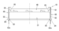
- FIG. 7A is a cross-sectional view showing the connection location between the split seal members Plan view of the space reduction state, showing the connection location between the split seal members
- FIG. 7C is a cross-sectional view showing the connection location between the split seal members
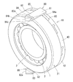
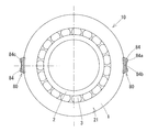
- Front view of a rolling bearing with a seal member Exploded perspective view of seal member
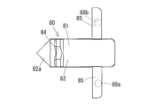
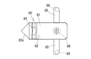
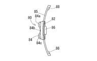
- the top view which shows the connection piece which connects division seal members
- the front view which shows the connection piece which connects division seal members
- the bearing unit 20 includes three rolling bearings 21, 22, and 23 that are oil-lubricated in parallel inside the housing 11. By these rolling bearings 21, 22, and 23, the shaft member 32 that communicates with the operating mechanism portion 30 of the oil pump 60 is supported by the fixed housing 11 so as to be rotatable about the axis.
- the outer ring 1 is press-fitted into the inner diameter surface of the housing 11 and is fixed so as not to rotate relative to the housing 11.
- the inner ring 2 is press-fitted into the outer periphery of the shaft member 32 and is fixed to the shaft member 32 so as not to rotate relative to the shaft member 32.
- the operating mechanism 30 of the oil pump 60 includes a pump rotor (not shown) that feeds lubricating oil to the circulation path by rotating relative to each other in the pump casing.
- the pump rotor is connected to the connection member 31 provided at the end of the shaft member 32, and is thus rotatable around the shaft of the shaft member 32.
- the driving force to the rotor is input by a separate route from a driving source (not shown).
- the rolling bearings 23, 22, 23 arranged in parallel to each other in the axial direction, that is, the rolling bearing 23 farthest from the operating mechanism portion 30 is arranged so that the end surface on the small diameter side of the tapered roller is on the operating mechanism portion 30 side. ing. That is, the rolling bearings 21 and 22 and the rolling bearing 23 are disposed so that the small diameter side end surfaces of the tapered rollers are back to back. For this reason, the raceway surface 2a of the inner raceway ring 2 and the raceway surface 1a of the outer raceway ring 1 are two on one side of the three rows of rolling bearings 21, 22, 23 from the one side in the axial direction to the other side. The other side is provided so that the mutual distance increases from one side in the axial direction to the other side.
- Both ends of the rolling bearings 21, 22, and 23 that are arranged in parallel are on the one side in the axial direction by the end face of the flange-shaped connection member 31 provided at the end of the shaft member 32, and on the other side in the axial direction, The end face is fixed so as not to move in the axial direction with respect to the shaft member 32.
- a preload is applied to each tapered roller bearing by fixing the connecting member 31 and the pressing member 8.
- the circulation path 13 includes an axial lubrication path 13a provided along the axial direction so as to be concentric with the axis of the shaft member 32 from the oil pump side, and an end of the lubrication path 13a.
- a radial lubrication path 13b that extends radially outward and opens on the outer peripheral surface of the shaft member 32 is provided. Since the radial lubrication path 13b opens to the annular space C sandwiched between the rolling bearings 22 and 23, the circulation path 13 passes through the annular space C on one side in the axial direction (left side in the figure). Is connected to the bearing spaces of the rolling bearings 21 and 22, and the other axial side (the right side in the figure) is connected to the bearing space of the rolling bearing 23.
- the lubricating oil that has passed through the bearing space of the rolling bearing 23 through the annular space C passes through the opening of the bearing space on the other end side in the axial direction of the rolling bearing 23 and the housing end provided on the other end side in the axial direction of the rolling bearing 23. Enter the subspace B. Thereafter, the oil returns to the operating mechanism 30 side of the oil pump 60 by the lubricating oil circulation path 12 formed in the portion near the outer diameter in the housing 11.
- the circulation path 12 includes a radial lubrication path 12b extending radially outward from the housing end space B, and an axial lubrication path 12a provided along the axial center direction of the shaft member 32 from the radial lubrication path 12b.
- the lubricating oil that has passed through the annular space C and the bearing space of the rolling bearings 22, 21 passes through the side opening D of the bearing space on one end side in the axial direction of the rolling bearing 21, and is on the side of the operating mechanism 30 of the oil pump 60. Go back to.
- the seal ring 40 is attached to the housing 11 and the outer ring 1 so as to cover the side opening D of the bearing space on one end side in the axial direction of the rolling bearing 21 and the opening 12c on one end side in the axial direction of the circulation path 12. Since the side opening D of the bearing space on one end side in the axial direction of the rolling bearing 21 is formed in an annular shape along the raceway surfaces 1a and 2a of the outer ring 1 and the inner ring 2, the seal ring 40 covering the ring D also forms an annular shape. It has become a thing.
- the seal ring 40 is brought into contact with the end face of the rolling bearing 21, and is housed in the housing 11 together with the other rolling bearings 22, 23, spacers 5, 6, 7, and the like.
- the seal ring 40 is not limited to a two-divided configuration using two split seal members 40 ′ having a central angle of 180 °, but, for example, by using four split seal members 40 ′ having a central angle of 90 °,
- the seal ring 40 may be configured, or the annular seal ring 40 may be configured by using six divided seal members 40 ′ having a central angle of 60 °.
- the connecting piece 80 is provided with an axial member 82 that extends in the axial direction from the base 81 contacting the outer peripheral surface of the cylindrical portion 42 of the seal ring 40 toward the rolling bearing 21.
- the axial member 82 extends between the inner diameter surface of the housing 11 and the outer diameter surface of the outer ring 1 and extends toward the rolling bearing 21, and the axial member 82 engages with a bearing member such as a bearing ring or a spacer.
- a bearing member such as a bearing ring or a spacer.
- the opening 12c on one end side in the axial direction of the circulation path 12 is located on the outer diameter side of the side opening D of the bearing space of the rolling bearing 21 having an annular shape in a side view.
- two axial lubrication paths 12a of the circulation path 12 are provided and have openings 12c at two positions with an interval of 180 ° along the circumferential direction. The number may be increased or decreased as necessary.
- the clearance between the recess 84b and the inner surface of the circulation path 12 and the inner diameter of the oil passage hole 84c are set to be equal to or smaller than the mesh size of the filter 46.
- a plurality of through holes and slits may be provided in the outer diameter side protruding portion 84 to provide a filter for capturing foreign matter.
- locking protrusions 88a and 88b are provided at the tip of each support portion 85 as locking portions 88 that protrude toward the inner diameter side.
- the engagement protrusions 88a and 88b enter engagement holes 48a and 48b, which are the engagement portions 48 provided at the ends of the divided seal members 40 ′ adjacent in the circumferential direction, so that the connecting piece 80 is The ends of the divided seal members 40 ′ adjacent in the circumferential direction are connected to each other.
- segmentation sealing member 40 ' is comprised by the annular
- a locking projection 89 that engages with the edge of the locking holes 48a and 48b may be provided at the tips of the locking projections 88a and 88b. If the retaining projection 89 is provided, separation between the connecting piece 80 and the divided seal member 40 ′ can be prevented.
- the retaining protrusions can also be provided on the locking holes 48a and 48b side. In this case, it is preferable to provide a retaining recess for fitting the retaining projection on the side of the locking projections 88a and 88b.
- the locking portion 88 of the connecting piece 80 and the locked portion 48 of the divided seal member 40 ′ are spaced in the circumferential direction between the connecting portions of the respective divided seal members 40 ′ and the connecting piece 80 adjacent in the circumferential direction. It functions as an interval adjusting means that makes it possible to adjust. That is, the distance adjusting means is a distance in the circumferential direction between the connecting portion between the one divided seal member 40 ′ and the connecting piece 80 facing each other and the connecting portion between the other divided seal member 40 ′ and the connecting piece 80. Can be adjusted.
- locking holes 48a and 48b are provided as locked portions 48 at the circumferential ends of the opposed split seal members 40 ′, respectively.
- 48b include a plurality of connecting portions with the locking portion 88 along the circumferential direction of the seal ring 40.
- the locking projections 88a and 88b constituting the locking portion 88 are cylindrical and have a circular cross section, so that the locking holes 48a and 48b are locking protrusions 88a and 88b having a circular cross section.
- are provided at a plurality of locations along the circumferential direction of the seal ring 40 in the figure, reference numbers A, B, C, D, reference numbers A ′, B ′, C ′, D ′, respectively). .
- the engaging projections 88a and 88b provided in the connecting piece 80 are connected to any connecting portions A, B, C and D; A ′, B ′ and C ′ of the engaging holes 48a and 48b provided in the divided seal member 40 ′.
- D ′ can be used to adjust the connection interval in the circumferential direction between the divided seal members 40 ′.
- the gap between the cylindrical portions 42 of the divided seal members 40 ′ adjacent in the circumferential direction is constituted by the notches 49 provided at the circumferential end portions of the divided seal members 40 ′. Since the gap due to the notch 49 is closed by the base portion 81 of the connecting piece 80, it is possible to omit providing the above-described key-like portion in the cylindrical portion.
- this last clearance w is the same as the inner diameter of the hole 46a of the filter 46, but the lubricating oil is allowed to pass through, but the passage of foreign matter exceeding that dimension is blocked. For this reason, the last clearance w between the inner diameter side end of the wall 43 and the outer surface of the large collar of the inner ring 2 is set to be equal to or smaller than the mesh size of the filter 46.
- a sensor unit that detects adhesion of foreign matter such as metal powder may be provided around the hole 46a of the filter 46 provided in the seal ring 40.
- the sensor unit for example, it is possible to employ an electric sensor that detects the presence of a foreign substance by a change in electrical output when the foreign substance is short-circuited between the electrodes due to the presence of a foreign substance between a pair of electrodes. it can.
- the output detection device connected through the cable from the pair of electrodes is connected between the pair of electrodes.
- the change in the electrical output of the electric circuit can be detected by the conduction through the foreign matter, and the state (content) of the foreign matter made of a metal contained in the lubricating oil can be detected.
- the cable connected to the pair of electrodes is drawn out of the housing 11 through the substrate, and an output detection device connected to the cable is provided in any part.
- a sensor hole for drawing the cable out of the seal ring 40 can be provided in the cylindrical portion 42 or the wall portion 43 of the seal ring 40.
- the end portions of the split seal member 40 ′ are engaged with the key-like portions 47 a and 47 b provided on the wall portion 43 and facing each other, so that the connection is further strengthened. It has become.
- a convex portion 44 that protrudes toward the inner diameter side is provided at the inner diameter side end of the wall 43 of the seal ring 40. Since this convex portion is in sliding contact with the outer diameter surface of the inner ring 2, the inner diameter side end portion of the wall portion 43 is not in contact with the outer diameter surface of the inner ring 2 at a place other than the convex portion 44.
- the convex portions 44 are arranged symmetrically across the bearing center of the rolling bearing 21.
- the seal ring 40 is a ring-shaped coupling body in which a plurality of divided sealing members 40 ′ divided along the circumferential direction are connected by a coupling piece 80. It is provided at an intermediate point between connecting pieces adjacent in the circumferential direction. For this reason, the seal ring 40 is provided with convex portions 44 at two locations along the circumferential direction.
- the seal ring 40 is worn by only the convex portion 44 being in sliding contact with the inner ring 2, but the other portions are not worn. For this reason, even if a member constituting the seal ring 40 includes a dimensional error within the tolerance at the time of manufacture, the end between the inner diameter side end of the wall portion 43 of the seal ring 40 and the outer diameter surface of the inner ring 2 is the last. The clearance w does not fall below the protruding height w1 of the convex portion 44. For this reason, it can prevent that parts other than the convex part 44 are slidably contacted with the inner ring
- the convex portion 44 is in sliding contact with the outer diameter surface of the inner ring 2, so that the inner diameter side end of the wall portion 43 of the seal ring 40 and the outer diameter surface of the inner ring 2 are in contact with each other.
- the last clearance w between them does not fall below the protruding height w1 of the convex portion 44. For this reason, even when the seal ring 40 is thermally expanded, it is possible to prevent a portion other than the convex portion 44 from being in sliding contact with the inner ring 2 and being worn.
- the size of the convex portion 44 is set to a minute protrusion amount such that the glass fiber does not easily enter the concave portion in the mold corresponding to the convex portion 44 when the fiber reinforced resin containing glass fiber is filled in the mold frame. It is desirable.
- the protrusion height w1 of the protrusion 44 is also set to 0.3 mm.
- the width w2 of the convex portion 44 in the axial direction of the rolling bearing 21 and the width w3 of the convex portion 44 in the circumferential direction of the rolling bearing shown in FIG. 11 can be freely set based on the required wear resistance performance.
- the material of the seal singing 40 including the convex portion 44 is made of fiber synthetic resin, but the convex portion 44 that contacts the outer diameter surface of the inner ring 2 may be used as another material having high wear resistance. Good. For example, you may employ
- the convex portion 44 is made of a material different from the main body of the seal ring 40, a member including the convex portion 44 that is a separate member from the main body of the seal ring 40 is integrated by various methods such as fitting, fixing, and welding. Can be
- the outer ring locking projection 45 is made of a material having a low coefficient of linear expansion different from that of the seal ring 40.
- the detachable member 50 including the outer ring locking projection 45 is a separate member from the main body of the seal ring 40, and the member is integrated by various methods such as fitting, fixing, and welding.
- a synthetic resin having a low linear expansion coefficient, a metal, or the like may be employed as the material of the detachable member 50.
- the outer ring locking projection 45 may be formed integrally with the seal ring 40.
- a sensor unit that detects adhesion of foreign matter such as metal powder may be provided around the hole 46a of the filter 46 provided in the seal ring 40.
- the sensor unit for example, it is possible to employ an electric sensor that detects the presence of a foreign substance by a change in electrical output when the foreign substance is short-circuited between the electrodes due to the presence of a foreign substance between a pair of electrodes. it can.
- the filter 46 is provided in the seal ring 40.
- the present invention can be applied to a seal ring 40 that does not include the filter 46.
- the present invention can be applied to an integral annular seal ring 40 that is not a split type.
- FIGS. 15A to 21C show a third embodiment of the present invention.
- the basic configuration of the apparatus shown in FIGS. 15A to 18 also corresponds to FIGS. 1A to 4 of the first embodiment described above.
- description of common points with the first embodiment will be omitted, and the difference will be mainly described.
- the seal ring 40 in this embodiment is attached to the end of the rolling bearing 21 so that the connecting piece 80 is located at least in the lower part of the seal ring 40.
- the connecting piece 80 is located at two locations, the upper portion and the lower portion of the seal ring 40. ing.
- the connecting pieces 80 are provided at the uppermost part and the lowermost part of the seal ring 40, respectively.
- the annular seal ring 40 is configured by dividing the seal ring 40 into two parts and using two divided seal members 40 ′ having a central angle of 180 °.
- the central angle is 180 °. It may be other than.
- an annular seal ring 40 may be configured by using four divided seal members 40 ′ having a central angle of 90 °, or an annular shape by using six divided seal members 40 ′ having a central angle of 60 °.
- the seal ring 40 may be configured.
- the connecting piece 80 is provided with a pair of support portions 85 extending from the base portion 81 to both sides in the circumferential direction.
- the support portion 85 is a cylindrical surface member along the outer diameter surface of the seal ring 40.
- a locking projection 88 that protrudes toward the inner diameter side is provided at the tip of each support portion 85.
- the engaging protrusions 88 enter the engaging holes 48 provided at the end portions of the divided seal members 40 ′ adjacent in the circumferential direction, so that the connecting piece 80 is divided into the divided seal members 40 ′ adjacent in the circumferential direction. Connect the ends of each other. Thereby, the division
- a concave foreign matter catching portion 86 is provided on the inner surface of the connecting piece 80.
- the foreign matter catching portion 86 faces the notches 49 provided at the end portions of the divided seal members 40 ′ adjacent in the circumferential direction. For this reason, the foreign matter catching part 86 is opened in a concave shape toward the bearing space side which is the inner side of the sealing 40. That is, in the connecting piece 80 located at the lower part of the seal ring 40, the foreign matter catching portion 86 has an upward concave shape facing the bearing space side.
- the foreign matter catching portion 86 includes a foreign matter discharge port 87 that vertically penetrates the inner diameter side and the outer diameter side, that is, the bearing space side and the outside of the bearing space, which is the opposite side, across the connecting piece 80.
- the foreign matter discharge port 87 can discharge foreign matter having a size smaller than the foreign matter capturing portion detection threshold set in the sensor unit 90 to the outside of the bearing space. That is, the inner diameter of the foreign substance discharge port 87 is set to be smaller than the minimum diameter of the foreign substance to be detected by the sensor unit 90.
- the foreign matter catching part 86 is an upward concave pocket, and in particular, in this embodiment, the concave part of the foreign matter catching part 86 has a funnel shape.
- the foreign matter discharge ports 87 are distributed throughout the funnel-shaped recess.
- the filter 46 the gap in the opening 12 c of the circulation path 12, and the wall portion 43. Cannot pass through the gap between the inner diameter side end of the inner ring 2 and the outer diameter surface of the large collar of the inner ring 2, and is trapped and collected by those portions.
- the sensor unit 90 determines the amount of the accumulated foreign substance. I try to detect it.
- the foreign material having a size that cannot pass through the foreign material discharge port 87 stops at any portion between the inner surfaces of the funnel that gradually narrows according to the size. Therefore, the electrodes 91 and 92 can be reliably short-circuited. That is, the sensor unit 90 can efficiently capture and detect a foreign substance having a size equal to or greater than the foreign substance capturing unit detection threshold, and can also detect the particle size of the detected foreign substance from the amount of change in electrical output.
- the sensor unit 90 it is possible to grasp the amount of foreign matter mixed in the lubricating oil.
- two pairs of electrodes 91a and 92a; 91b and 92b are provided, and the electrode distance between the first pair of electrodes 91a and 92a that are relatively far apart is relatively long.
- both of the near second pair of electrodes 91b and 92b are short-circuited by the foreign matter, it can be determined that the first rank has a large amount of foreign matter accumulated and a large amount of foreign matter mixed into the lubricating oil.
- the inner surface of the foreign material catching portion 86 has a funnel shape that narrows toward the outer diameter side of the rolling bearing, but the inner surface shape of the foreign matter catching portion 86 may be, for example, a cylindrical shape. However, it is desirable that the inner surface of the foreign matter catching portion 86 provided at the lower portion of the seal ring 40 is concave upward.
- an electric sensor is adopted as the sensor unit 90.
- an optical sensor that detects the presence of a foreign substance by light may be adopted.
- a sensor unit that detects adhesion of foreign matter such as metal powder may be provided around the hole 46a of the filter 46 provided in the seal ring 40.
- the sensor unit for example, it is possible to employ an electric sensor that detects the presence of a foreign substance by a change in electrical output when the foreign substance is short-circuited between the electrodes due to the presence of a foreign substance between a pair of electrodes. it can.
- the output detection device connected through the cable from the pair of electrodes is connected between the pair of electrodes.
- the change in the electrical output of the electric circuit can be detected by the conduction through the foreign matter, and the state (content) of the foreign matter made of a metal contained in the lubricating oil can be detected.
- the cable connected to the pair of electrodes is drawn out of the housing 11 through the substrate, and an output detection device connected to the cable is provided in any part.
- a sensor hole for drawing the cable out of the seal ring 40 can be provided in the cylindrical portion 42 or the wall portion 43 of the seal ring 40.
- the interval adjusting means in the first embodiment can be applied to each of the second embodiment and the third embodiment.
- the convex part which is provided at the inner diameter side end of the seal member in the second embodiment and is in sliding contact with the outer diameter surface of the inner ring is also applicable in the third embodiment.
Landscapes
- Engineering & Computer Science (AREA)
- General Engineering & Computer Science (AREA)
- Mechanical Engineering (AREA)
- Rolling Contact Bearings (AREA)
Abstract
外輪(1)と内輪(2)との間の軸受空間の側方開口Dを覆う円環状のシール部材(40)を、周方向に沿って分割された複数の分割シール部材(40')が連結片(80)によって接続された円環状の連結体で構成し、周方向に隣り合う前記各分割シール部材(40')と連結片(80)との接続部間の周方向への間隔を調整可能とする間隔調整手段を備える転がり軸受ユニットである。
Description
この発明は、オイル潤滑される転がり軸受に関し、特に、潤滑用のオイルに含まれる異物の捕捉する機能を備えた転がり軸受ユニットに関するものである。
輸送機器や産業機械、その他各種機器の可動部には、転がり軸受が組み込まれている。このような機器の中には、油潤滑される転がり軸受以外に潤滑が必要な作動機構部を有し、その作動機構部と転がり軸受とが、共通のオイルで潤滑される構造となっているものがある。作動機構部としては、例えば、ギヤ同士の噛み合い部分や部材同士の摺接部分等が挙げられる。
例えば、オイルポンプ等は、機器の内部に転がり軸受と作動機構部とを有している。また、特に、オイルポンプは、その転がり軸受と作動機構部とを備えた機器の外部にある他の作動機構部に向かって、内部の潤滑油を送り出す機能を備えている。
ところで、転がり軸受の軸受空間からは、摩耗粉(鉄粉等)等の異物が発生することがある。この異物が、潤滑油の循環経路の途中にある作動機構部に侵入すると、異物の噛み込みによって、機器の耐久性を低下させる場合がある。また、場合によっては、機器の動作不良・故障・破損に繋がることもある。
そこで、例えば、下記特許文献1には、鉄粉等からなる異物が循環経路内に流通する潤滑油に混入した場合に、その異物をセンサが備える磁石に吸着させ、吸着した異物が堆積していくことにより金属製のケーシングと磁石とが電気的に導通した場合に、警報を発信する潤滑油の鉄粉汚濁検知方法が開示されている。
また、下記特許文献2には、転がり軸受の内外輪間に位置する軸受空間の端部を閉じるシールリングに、異物を捕捉するフィルタを設けた技術が開示されている。
上記のように、転がり軸受から発生する摩耗粉(鉄粉等)等の異物が、潤滑油の循環経路の途中にある作動機構部に侵入することは好ましくない。特に、オイルポンプ用の転がり軸受ユニットにおいて、軸受から発生する大きな剥離片は、そのオイルポンプ自身の作動機構部や、そのオイルポンプによって送り出される潤滑油の循環経路内にある他の作動機構部の部品に対して、動作不良・故障・破損の原因となる。このため、特許文献2に示すような、フィルタ付きの円環状のシール部材を設置することで、転がり軸受内から作動機構部への異物の流出防止が必要となる。
ところで、シール部材を外輪側に固定した場合、そのシール部材の内径側端部は、内輪の外径面に摺接するか、あるいは、わずかな隙間を介して対向する。このシール部材の内径側端部と内輪の外径面との半径方向への隙間を「最後すきま」と称している。
最後すきまは、転がり軸受内から作動機構部へ異物が流出しないよう、シール部材のフィルタのメッシュサイズと同一か、あるいは、それ以下の寸法に設定されなければならない。このため、シール部材を転がり軸受に取り付けた際、あるいは、取り付けた後も、最後すきまの寸法は管理されなければならない。
しかし、シール部材には、その製造時に公差内の寸法誤差が発生する。この寸法誤差は、シール部材が樹脂製である場合は相対的に大きくなる。
この寸法誤差により、シール部材の内径側端部と内輪の外径面とが摺接してしまう場合がある。また、シール部材が熱膨張することにより最後すきまが縮小して、シール部材の内径側端部と内輪の外径面とが摺接してしまう場合もある。シール部材と内輪とが強く摺接するとシール部材が摩耗するので、最後すきまがさらに拡大する可能性があるので好ましくない。
そこで、この発明の第一の課題は、シール部材の内径側端部と内輪の外径面との半径方向への隙間である最後すきまの寸法を、より適切に管理できるようにすることである。
また、上記のように、転がり軸受から発生する摩耗粉(鉄粉等)等の異物が、潤滑油の循環経路の途中にある作動機構部に侵入することは好ましくないことから、フィルタの設置による転がり軸受内から作動機構部への異物の流出防止や、センサの設置による異物の検出が必要となる。
しかし、上記特許文献1に記載の技術では、センサの感度が良すぎる場合に、本来は、特許文献2に示すようなフィルタで除去されるべき大きさの異物を感知して、警報の誤作動につながるという問題がある。大きな異物はフィルタによって捕捉され作動機構部には入り込まないので、センサは、フィルタのメッシュサイズ以上の大きさの異物は必ずしも感知する必要がない。むしろ、センサには、潤滑油内におけるフィルタを通過し得る大きさの異物の含有量が所定の量を超えた場合に、作動機構部に悪影響を及ぼす可能性がある旨の警報を発信することが求められる。
さらに、特許文献1のようなセンサを転がり軸受に設置すると、構造が複雑になるという問題もある。潤滑油に混入した異物を検知するためのセンサは、できる限り簡素な構造で転がり軸受に設置できることが望ましい。
そこで、この発明の第二の課題は、転がり軸受ユニットの軸受から発生する摩耗粉(鉄粉等)等の異物が潤滑油に混入した際に、その潤滑油に含まれる異物の量を的確に検知することであり、さらに、異物を検出するセンサをできる限り簡素な構造で転がり軸受に設置できるようにすることである。
上記第一の課題を解決するために、この発明は、外輪及び内輪と、前記外輪と前記内輪との間の軸受空間に配置される転動体と、前記外輪又は前記外輪に固定された部材に取り付けられて前記軸受空間の側方開口を覆う円環状のシール部材と、を備え、前記シール部材は周方向に沿って分割された複数の分割シール部材が連結片によって接続されて円環状の連結体となっており、周方向に隣り合う前記各分割シール部材と前記連結片との接続部間の周方向への間隔を調整可能とする間隔調整手段を備える転がり軸受を採用した。
ここで、前記間隔調整手段は、前記連結片に設けられた係止部と、前記分割シール部材に設けられ前記係止部が係止される被係止部とで構成され、前記被係止部を前記分割シール部材の周方向端部に周方向に沿って複数備える構成を採用することができる。
あるいは、前記間隔調整手段は、前記分割シール部材に設けられた係止部と、前記連結片に設けられ前記係止部が係止される被係止部とで構成され、前記被係止部を前記連結片に周方向に沿って複数備える構成を採用することができる。
その各態様において、前記係止部と前記被係止部の一方は凸部であり、他方は一方が嵌合する凹部である構成を採用することができる。
前記凸部又は前記凹部に、前記凸部が前記凹部から抜け出すのを防止する抜け止め用突起を備える構成を採用することができる。
前記シール部材は、前記外輪の端面に当接する円筒部と、前記円筒部の筒軸方向一端部から内径側に向かって立ち上がる壁部とを備え、周方向に隣り合う前記各分割シール部材は、対向する前記壁部又は対向する前記円筒部に互いに噛み合うカギ状部を備える構成を採用することができる。
また、前記シール部材は、前記外輪の端面に当接する円筒部と、前記円筒部の筒軸方向一端部から内径側に向かって立ち上がる壁部とを備え、周方向に隣り合う前記各分割シール部材の対向する前記円筒部の周方向端部間の隙間は、前記連結片によって閉じられる構成を採用することができる。
また、上記第一の課題を解決するために、この発明は、外輪及び内輪と、前記外輪と前記内輪との間の軸受空間に配置される転動体と、前記外輪又は前記外輪に固定された部材に取り付けられて前記軸受空間の側方開口を覆う円環状のシール部材と、前記シール部材の内径側端部に設けられ前記内輪の外径面に摺接する凸部と、を備える転がり軸受を採用した。
ここで、前記凸部は軸受中心を挟んで対称に配置される構成を採用することができる。
また、前記シール部材は周方向に沿って分割された複数の分割シール部材が連結片によって接続されて円環状の連結体となっており、前記凸部を、周方向に隣り合う前記連結片間を等分方位に分割する地点に備える構成を採用することができる。
前記シール部材は繊維強化樹脂製である構成を採用することができる。
前記シール部材は、前記外輪の端面に当接する円筒部と、前記円筒部の筒軸方向一端部から内径側に向かって立ち上がる壁部とを備え、前記円筒部に前記外輪の内径面に係合してシールリングの半径方向への移動を拘束する外輪係止凸部を備える構成を採用することができる。
前記外輪はハウジング内に固定され、前記シール部材は、前記外輪の端面に当接する円筒部と、前記円筒部の筒軸方向一端部から内径側に向かって立ち上がる壁部とを備え、前記円筒部に前記ハウジングの内径面に当接してシールリングの半径方向への移動を拘束するハウジング当接部を備える構成を採用することができる。
さらに、上記第二の課題を解決するために、この発明は、外輪及び内輪と、前記外輪と前記内輪との間の軸受空間に配置される転動体と、前記外輪又は前記内輪のうち静止側の軌道輪若しくはその静止側の軌道輪に固定された部材に取り付けられて前記軸受空間の側方開口を覆う円環状のシール部材と、前記シール部材の下部に設けられる異物捕捉部と、前記異物捕捉部に設けられ潤滑油に含まれる異物を検知するセンサ部と、を備える転がり軸受を採用した。
ここで、前記シール部材は周方向に沿って分割された複数の分割シール部材が連結片によって接続されて円環状の連結体となっており、前記異物捕捉部は前記連結片に設けられる構成を採用することができる。
また、前記センサ部は、対の電極間への金属からなる異物の付着を電気的に検出する構成を採用することができる。
さらに、前記異物捕捉部は、前記シール部材を挟んで前記軸受空間側とその反対側とを上下方向に貫通する異物排出口を備える構成を採用することができる。
前記異物捕捉部は上向き凹状のポケットである構成を採用することができる。特に、前記異物捕捉部の凹部は漏斗状であり、前記異物排出口は漏斗状の凹部内に位置し、前記対の電極は、前記凹部内に上下方向に沿ってその電極間隔の異なるものが複数組備えられる構成を採用することができる。
この発明は、外輪と内輪との間の軸受空間の側方開口を覆う円環状のシール部材を、周方向に沿って分割された複数の分割シール部材が連結片によって接続して円環状の連結体として構成し、周方向に隣り合う各分割シール部材と連結片との接続部間の周方向への間隔を調整可能とする間隔調整手段を備えたので、シール部材の内径側端部と内輪の外周面との半径方向への隙間である最後すきまの寸法を、より適切に管理できるようになる。
また、この発明は、軸受空間の側方開口を覆う円環状のシール部材の内径側端部に、内輪の外径面に摺接する凸部を備えたので、シール部材の内径側端部と内輪の外周面との半径方向への隙間である最後すきまの寸法を、より適切に管理できるようになる。
さらに、この発明は、転がり軸受の静止側の軌道輪に取り付けられて軸受空間の側方開口を覆う円環状のシール部材と、シール部材の下部に設けられる異物捕捉部と、異物捕捉部に設けられ潤滑油に含まれる異物を検知するセンサ部とを備えたので、潤滑油に含まれる異物はその自重によって沈降し異物捕捉部に収容される。このため、自重によって沈降した異物をセンサ部で検知すれば、潤滑油に含まれる異物の量を的確に検知することができる。特に、例えば、夜間に操業して昼間に稼働する機器等、間欠的に使用される機器等では、転がり軸受の回転が停止している間に対象となる異物を効果的に沈降させることができるので、より的確な異物の検知が可能である。
また、複数の分割シール部材を連結片によって接続して円環状のシール部材が構成され、異物捕捉部を連結片に設けたので、異物を検出するセンサを簡素な構造で転がり軸受に設置できる。
この発明の実施形態を、図面に基づいて説明する。この実施形態は、シール部材40を取り付けた軸受ユニット20を備えたオイルポンプ装置10である。図1A~図7Dは、第一の実施形態を示す。
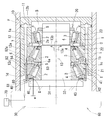
オイルポンプ装置10は、機器の内部に転がり軸受を複数備えた軸受ユニット20と、オイルポンプ60の作動機構部30とを有している。
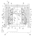
軸受ユニット20は、ハウジング11の内部に、油潤滑される3つの転がり軸受21,22,23を並列して備えている。これらの転がり軸受21,22,23によって、オイルポンプ60の作動機構部30に通じる軸部材32を、固定のハウジング11に対して軸周り回転自在に支持している。
各転がり軸受21,22,23は、外側軌道輪1と内側軌道輪2の各軌道面1a,2aの間に、転動体3が組み込まれている。転動体3は、保持器4によって周方向に保持されている。以下、外側軌道輪1を外輪1と、内側軌道輪2を内輪2と称する。
外輪1はハウジング11の内径面に圧入されて、そのハウジング11に対して相対回転不能に固定されている。内輪2は、軸部材32の外周に圧入されて、その軸部材32に対して相対回転不能に固定されている。
この実施形態では、転がり軸受21,22,23として、転動体3として円すいころを用いた円すいころ軸受を採用しているが、円すいころ軸受以外の転がり軸受を採用してもよく、また、その転がり軸受21,22,23の並列数は、装置の仕様に応じて自由に設定できる。
オイルポンプ60の作動機構部30は、ポンプケーシング内に互いに相対回転することにより潤滑油を循環経路へ送り出すポンプ用ロータ(図示せず)を備える。ポンプ用ロータは、軸部材32の端部に設けた接続部材31に接続され、これにより、軸部材32の軸周りに回転可能な状態である。ロータへの駆動力は、図示しない駆動源から別途のルートで入力される。
図1A、図1Bに示すように、並列する転がり軸受21,22,23のうち軸方向一方側、すなわち、作動機構部30寄りの2つの転がり軸受21,22は、円すいころの小径側端面同士が軸方向に沿って同じ側、すなわち、作動機構部30の反対側になるように配置されている。
また、並列する転がり軸受21,22,23のうち軸方向他方側、すなわち、作動機構部30から最も遠い転がり軸受23は、円すいころの小径側端面が作動機構部30側になるように配置されている。すなわち、転がり軸受21,22と転がり軸受23とは、円すいころの小径側端面同士が背面合わせになるように配置されている。このため、内側軌道輪2の軌道面2aと外側軌道輪1の軌道面1aとは、3列の転がり軸受21,22,23のうち一方側の二つは、軸方向一方側から他方側へ向かって互いの距離が狭まるように設けられ、他方側の一つは、軸方向一方側から他方側へ向かって互いの距離が拡がるように設けられている。
図1Bに示すように、軸方向に隣り合う転がり軸受21,22,23同士の間には、間座5,6,7が配置されている。
並列する転がり軸受21,22,23のうち軸方向一方側の2つの転がり軸受21,22の間には、内径側に、両側の内輪2,2の端面に当接する間座5が、外径側に、両側の外輪1,1の端面に当接する間座6が配置されている。
また、並列する転がり軸受21,22,23のうち軸方向他方側の2つの転がり軸受22,23の間には、内径側に、両側の内輪2,2の端面に当接する間座が、外径側に、両側の外輪1,1の端面に当接する間座7が配置されている。図1Bでは、転がり軸受22,23の間における内径側の間座は図示していないが、転がり軸受22,23の周方向に沿って、潤滑油の循滑経路13bの外径側の開口部以外の部分に、間座が配置されている。
並列する転がり軸受21,22,23の両端は、軸方向一方側では、軸部材32の端部に設けたフランジ状の接続部材31の端面によって、また、軸方向他方側では、押え部材8の端面によって、軸部材32に対して軸方向へ動かないように固定されている。これらの接続部材31と押え部材8との固定によって、各円すいころ軸受には予圧が付与されている。
転がり軸受21,22,23によってハウジング11に支持された軸部材32は、オイルを送り出すためのポンプ本体に相当するオイルポンプ60内の回転部材である作動機構部30に接続されている。オイルポンプ60は、その駆動によって、外部にある他の作動機構部70に向かって、内部の潤滑油を送り出す機能を備えている。送り出した潤滑油は、潤滑油の経路に沿って流れて各部の作動機構部70を潤滑した後、やがてオイルポンプ60に戻ってくる。
また、このオイルポンプ60においては、ポンプ本体内の作動機構部30と、その作動機構部30に通じる軸部材32を支える軸受ユニット20とが、共通の潤滑用のオイルで潤滑されるようになっている。オイルポンプ60側の作動機構部30と軸受ユニット20側の軸受空間とは、軸方向一方側の転がり軸受21の軸方向一端側の軸受空間の側方開口D、及び、潤滑油の循環経路12,13を通じて連通している。また、その潤滑油は、ポンプ外の作動機構部70にも送り出される。
この実施形態において、循環経路13は、オイルポンプ側から軸部材32の軸心と同心となるように軸心方向に沿って設けられた軸方向潤滑経路13aと、その潤滑経路13aの端部から半径方向外側へ伸びて、軸部材32の外周面に開口する径方向潤滑経路13bを備える。径方向潤滑経路13bは、転がり軸受22,23の間に挟まれた環状空間Cに開口しているので、この環状空間Cを介して、循環経路13は、軸方向一方側(図中左側)へは転がり軸受21,22の各軸受空間に連通し、軸方向他方側(図中右側)へは転がり軸受23の軸受空間に連通している。
環状空間Cを経て、転がり軸受23の軸受空間を通過した潤滑油は、転がり軸受23の軸方向他端側の軸受空間の開口を通じて、転がり軸受23の軸方向他端側に設けられたハウジング端部空間Bに入り込む。その後、ハウジング11内の外径寄りの部分に形成された潤滑油の循環経路12によって、オイルポンプ60の作動機構部30側へと戻っていく。
循環経路12は、ハウジング端部空間Bから半径方向外側へ伸びる径方向潤滑経路12bと、その径方向潤滑経路12bから軸部材32の軸心方向に沿って設けられた軸方向潤滑経路12aとを備える。
また、環状空間Cを経て、転がり軸受22,21の軸受空間を通過した潤滑油は、転がり軸受21の軸方向一端側の軸受空間の側方開口Dを通じて、オイルポンプ60の作動機構部30側へと戻っていく。
これにより、オイルポンプの作動機構部30と、軸受ユニット20の転がり軸受21,22,23が、共通の潤滑油によって潤滑される。
ところで、転がり軸受21,22,23の軸受空間からは、摩耗粉(鉄粉等)等の異物が発生することがある。この異物が、オイルポンプ60の作動機構部30や、ポンプ外の循環経路途中にある他の作動機構部70に侵入することは好ましくない。そこで、転がり軸受21の軸方向一端側の軸受空間の側方開口D、及び、循環経路12の軸方向一端側の開口12c、すなわち、軸方向潤滑経路12aの開口12cにシール部材40(以下、実施形態では、円環状のシール部材40を用いているので、これをシールリング40と称する)が取付られている。
シールリング40は、転がり軸受21の軸方向一端側の軸受空間の側方開口D、及び、循環経路12の軸方向一端側の開口12cを覆うように、ハウジング11及び外輪1に取付けられる。転がり軸受21の軸方向一端側の軸受空間の側方開口Dは、外輪1と内輪2の軌道面1a,2aに沿って環状に形成されているので、それを覆うシールリング40も環状を成すものとなっている。
図1A~図3Bに示すように、シールリング40が転がり軸受21の端面に当接した状態とされ、他の転がり軸受22,23や間座5,6,7等とともにハウジング11内に収容される。
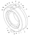
シールリング40は、図1Bに示すように、その筒軸方向端面41が、外輪1の軸方向一端側の端面1dに当接する円筒状部材からなる円筒部42と、円筒部42の筒軸方向一端部から内径側に向かって立ち上がる壁部43とを備える。
壁部43には、フィルタ46が設けられている。フィルタ46は、貫通穴からなるフィルタ孔46aの集合によって、転がり軸受21,22の軸受空間からの異物の通過を阻止し、潤滑油の通過は許容されるものである。このとき、フィルタ孔46aの内径は、少量であれば、作動機構部30側へ侵入しても影響がない程度の異物の通過は許容されるよう、適宜の寸法に設定される。
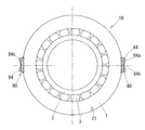
この実施形態では、シールリング40は合成樹脂の成形品からなるものとしている。また、シールリング40は、転がり軸受21の軸受空間の側方開口Dに沿う円環状を成し、その円環の周方向に沿って分割された複数の分割シール部材40’が、連結片80によって円環状に接続された連結体である。周方向に隣り合う分割シール部材40’同士は、連結片80により接続される。連結片80も、合成樹脂の成形品からなるものとしている。
この実施形態では、中心角180°を成す2つの分割シール部材40’で円環状のシールリング40を構成しているので、連結片80は、シールリング40の上部と下部の2箇所に位置している。
さらに、シールリング40が、中心角180°の分割シール部材40’を二つ用いた2分割構成だけでなく、例えば、中心角90°の分割シール部材40’を四つ用いることで円環状のシールリング40を構成してもよいし、中心角60°の分割シール部材40’を六つ用いることで円環状のシールリング40を構成してもよい。
また、この実施形態では、シールリング40は、壁部43のフィルタ46用の孔46aを、シールリング40の本体に一体に形成しているが、壁部43のフィルタ46を、シールリング40の本体の部材とは別部材として、その別部材をシールリング40の本体に、嵌め込み固定、埋め込み固定、接着等の種々の手段で固定するようにしてもよい。
シールリング40や連結片80の素材としては、樹脂以外にも、金属、ゴム等の他の素材を採用してもよい。フィルタ46をシールリング40とは別部材とする場合も、フィルタ46の素材として、樹脂、金属、ゴム等の他の素材を用いることができる。
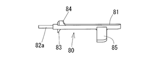
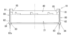
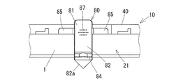
また、連結片80には、シールリング40の円筒部42の外周面に当接する基部81から、転がり軸受21側へ向かって軸方向へ伸びる軸方向部材82が設けられている。
軸方向部材82は、ハウジング11の内径面と外輪1の外径面との間を通って転がり軸受21側へ伸びて、その軸方向部材82が軌道輪や間座等の軸受部材に係合することにより、シールリング40はハウジング11及び外輪1に固定される。
この実施形態では、軸方向部材82は、循環経路12内を通って軸方向一端側から他端側へ向かって伸びており、その軸方向部材82の先端82aは先細りの形状となっている。このため、ハウジング11内への挿入がスムーズである。また、軸方向部材82の先端寄りには、内径側へ向かって伸びる内径側突出部83を備えている。
軸方向部材82は外輪1の外径面に接触しつつ、内径側突出部83が軸受の軌道輪や間座に設けた凹部に入り込むことで、シールリング40の軸方向への移動が規制される。この実施形態では、内径側突出部83が、転がり軸受21の外輪1bと間座6との間に形成された凹部1c内に入り込む構成としている。凹部1cは、間座6の一端側端面6aと、転がり軸受21の外輪1bの肩部の稜線部に形成された曲面状のアール部や面取り部等とによって構成されている。
また、循環経路12の軸方向一端側の開口12cは、側面視円環状を成す転がり軸受21の軸受空間の側方開口Dよりも外径側に位置する。この実施形態では、循環経路12の軸方向潤滑経路12aは2本設けられており、周方向に沿って180°の間隔をおいて2箇所に開口12cを有しているが、この開口12cの数は、必要に応じて増減してもよい。
連結片80は、循環経路12内側へ突出する外径側突出部84を備える。外径側突出部84は、軸方向部材82の外面から外径側へ向かって立ち上がり、その外径面に凸部84aと凹部84b、及び、通油孔84cを備える。凸部84aは、循環経路12の内面に当接して連結片80を支持し、凹部84bと循環経路12内面との隙間、及び、通油孔84cは、循環経路12から軸受空間外への潤滑油の通路となる。凹部84bと循環経路12の内面との隙間、通油孔84cの内径は、同じく、フィルタ46のメッシュサイズと同じか、そのメッシュサイズ以下に設定される。外径側突出部84に複数の貫通孔やスリットを設けて、異物を捕捉するためのフィルタとすることもできる。
また、軸方向部材82及び外径側突出部84は、循環経路12内に入り込んでがたつきなく固定されるよう、その幅(転がり軸受の周方向への幅)は循環経路12の幅(同じく転がり軸受の周方向への幅)と合致している。これにより、シールリング40は、ハウジング11及び外輪1に対して回り止めされる。すなわち、軸方向部材82及び外径側突出部84は、シールリング40の回り止め手段として機能している。
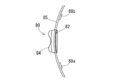
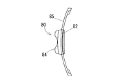
連結片80には、図5A、図5B、図5Cに示すように、基部81から周方向両側へ伸びる対の支え部85が設けられている。支え部85は、シールリング40の外径面に沿う円筒面状の部材である。
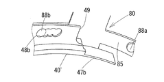
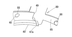
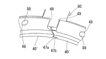
各支え部85の先端には、図6A、図6Bに示すように、内径側へ突出する係止部88として、係止凸部88a,88bが設けられている。この係止凸部88a,88bが、周方向に隣り合う分割シール部材40’の端部にそれぞれ設けられた被係止部48である係止孔48a,48bに入り込むことで、連結片80は、周方向に隣り合う分割シール部材40’の端部同士を接続する。これにより、分割シール部材40’は円環状の連結体に構成される。
このとき、図6Cに示すように、係止凸部88a,88bの先端に、係止孔48a,48bの縁に係合する抜け止め用突起89を備えさせてもよい。抜け止め用突起89があれば、連結片80と分割シール部材40’との分離を防ぐことができる。この抜け止め用突起は、係止孔48a,48b側に設けることもできる。この場合、係止凸部88a,88b側に抜け止め用突起が嵌る抜け止め用凹部を設けるとよい。
この連結片80の係止部88と、分割シール部材40’の被係止部48は、周方向に隣り合う各分割シール部材40’と連結片80との接続部間の周方向への間隔を調整可能とする間隔調整手段として機能している。すなわち、間隔調整手段は、対向する一方の分割シール部材40’と連結片80との接続部と、他方の分割シール部材40’と連結片80との接続部との間の周方向への間隔を調整することができる。
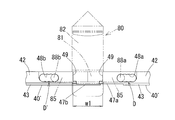
図7A、図7Bに示すように、対向する分割シール部材40’の周方向端部には、それぞれ被係止部48として係止孔48a,48bが設けられているが、この係止孔48a,48bは、シールリング40の周方向に沿って、係止部88との接続部を複数箇所備えている。図中に示すように、係止部88を構成する係止凸部88a,88bは円柱状であり断面円形を成すので、係止孔48a,48bはその断面円形の係止凸部88a,88bが嵌る接続部を、シールリング40の周方向に沿って複数箇所(図では、符号A,B、C、D、符号A’,B’、C’、D’のそれぞれ4箇所)備えている。
このため、連結片80が備える係止凸部88a,88bを、分割シール部材40’が備える係止孔48a,48bのどの接続部A,B、C、D;A’,B’、C’、D’へそれぞれ係止するかによって、分割シール部材40’同士の周方向への接続間隔を調整できる。
図7A、図7Bでは、連結片80が備える係止凸部88a,88bを、それぞれ分割シール部材40’が備える係止孔48a,48bの最も端部寄りの接続部D,D’へ係止することにより、分割シール部材40’同士の周方向への接続間隔をw1として広く確保している。これにより、シールリング40の壁部43の内径側端部と内輪2の大つば外径面との間の最後すきまwは、相対的に広く設定される。
図7C、図7Dでは、連結片80が備える係止凸部88a,88bを、それぞれ分割シール部材40’が備える係止孔48a,48bの端部から最も遠い接続部A,A’へ係止することにより、分割シール部材40’同士の周方向への接続間隔をw2として狭く確保している。これにより、シールリング40の壁部43の内径側端部と内輪2の大つば外径面との間の最後すきまwは、相対的に狭く設定される。
このとき、図6A、図6Bに示すように、周方向に隣り合う分割シール部材40’の壁部43同士は、互いに噛み合うカギ状部47a,47bを備えている。このため、互いに対向するカギ状部47a,47bが噛み合っているので、分割シール部材40’同士の接続がより強固となっている。また、分割シール部材40’同士の接続部間の距離がどのような状態であっても、カギ状部47a,47b同士の間に、すなわち、壁部43同士の間に、有害な異物を流出させるような隙間を生じさせないようにすることができる。
このようなカギ状部は、円筒部42にも備えてもよい。すなわち、周方向に隣り合う分割シール部材40’の円筒部42同士は、互いに噛み合うカギ状部を備えることによって、分割シール部材40’同士の接続部間の距離がどのような状態であっても、カギ状部同士の間に、すなわち、円筒部同士の間に、有害な異物を流出させるような隙間を生じさせないようにすることができる。
ただし、この実施形態では、周方向に隣り合う分割シール部材40’の円筒部42同士の隙間は、分割シール部材40’の周方向端部に設けられた切欠き49によって構成されている。この切欠き49による隙間は、連結片80の基部81によって塞がるので、前述のようなカギ状部を円筒部に設けることを省略することができる。
この間隔調整手段により、周方向に隣り合う各分割シール部材40’と連結片80との接続部間の周方向への間隔を調整することによって、シールリング40の直径が調整される。これにより、シールリング40の壁部43の内径側端部と内輪2の大つば外径面との最後すきまwを、適切な寸法に調整、管理することができる。
この最後すきまwの寸法は、フィルタ46の孔46aの内径と同様、潤滑油は通過が許容されるが、その寸法を超える異物の通過は阻止される。このため、壁部43の内径側端部と内輪2の大つば外径面との最後すきまwは、フィルタ46のメッシュサイズと同じか、そのメッシュサイズ以下に設定される。
上記の実施形態では、係止部88を凸部とし、被係止部48を凸部が嵌合する凹部としたが、係止部と被係止部とは凸部と凹部の組み合わせ以外で構成してもよい。
また、上記の実施形態では、間隔調整手段は、連結片80に設けられた係止部88と、分割シール部材40’に設けられた被係止部48とで構成し、被係止部48での係止部88との接続部を、分割シール部材40’に周方向に沿って複数備える構成を採用したが、この係止部88と被係止部48を逆に配置してもよい。
すなわち、間隔調整手段は、分割シール部材40’に設けられた係止部と、連結片80に設けられ係止部が係止される被係止部とで構成され、被係止部を連結片に周方向に沿って複数備える構成である。分割シール部材40’の係止部は、例えば凸部で構成することができ、連結片80の被係止部は、例えば凸部が嵌合する凹部で構成することができる。
また、対の係止部88の間隔が異なる連結片80を用意し、その複数種類の連結片80を使いわけることによって、周方向に隣り合う各分割シール部材40’と連結片80との接続部間の周方向への間隔を調整可能とする間隔調整手段とすることもできる。すなわち、対の係止部88の間隔が長い連結片80を用いれば、周方向に隣り合う分割シール部材40’の接続部間の間隔は長くなり、対の係止部88の間隔が短い連結片80を用いれば、周方向に隣り合う分割シール部材40’の接続部間の間隔は短くできる。
以上のように、転がり軸受21,22,23の軸受空間からの潤滑油は、シールリング40に設けたフィルタ46の孔46aや、循環経路12内の孔や隙間、あるいは、最後すきまの間隔が管理された前述の壁部43の内径側端部と内輪2の大つば外径面との隙間wを通過して、軸受空間外へ流出する。このため、作動機構部30、70の動作に影響が出るような大きな異物(金属からなる摩耗粉の他、特に剥離片等)は、作動機構部30、70側へは侵入しない。
上記の各実施形態において、シールリング40に設けられるフィルタ46の孔46a周辺に、金属粉等の異物の付着を検出するセンサ部を備えてもよい。センサ部としては、例えば、対の電極間に異物が介在することにより、その異物が電極間を短絡した際の電気的出力の変化によって、異物の存在を検知する電気式センサを採用することができる。
例えば、対の電極間に、フィルタ46の孔46aを通過できない大きさの金属からなる異物が付着することに伴って、その対の電極からケーブルを通じて接続された出力検出装置は、対の電極間の異物を介した導通によって、電気回路の電気的出力の変化を検出し、潤滑油に含まれる金属からなる異物の状態(含有量)を検知することができる。対の電極に接続されたケーブルは、基板を経由してハウジング11外に引き出されて、そのケーブルに接続された出力検出装置がいずれかの部分に設けられる。シールリング40外にケーブルを引き出すためのセンサ孔は、シールリング40の円筒部42や壁部43等に設けることができる。
図8A~図14Cに、この発明の第二の実施形態を示す。図8A~図11に示す装置の基本構成は、前述の第一の実施形態の図1A~図4に対応している。以下の第二の実施形態では、第一の実施形態との共通点の説明は省略し、その差異点を中心に説明する。
連結片80には、図12A、図12B、図12Cに示すように、基部81から周方向両側へ伸びる対の支え部85が設けられている。支え部85は、シールリング40の外径面に沿う円筒面状の部材である。各支え部85の先端には、内径側へ突出する係止凸部88が設けられている。この係止凸部88が、周方向に隣り合う分割シール部材40’の端部にそれぞれ設けられた係止孔48に入り込むことで、連結片80は、周方向に隣り合う分割シール部材40’の端部同士を接続する。これにより、分割シール部材40’は円環状の連結体に構成される。
また、分割シール部材40’の端部同士は、図13A、図13Bに示すように、壁部43に設けられ互いに対向するカギ状部47a,47bが噛み合っているので、その接続がより強固となっている。
また、シールリング40の壁部43の内径側端部は、内輪2の大つば外径面にわずかな隙間wを介して対向して、壁部43と内輪2との間に隙間(最後すきま)wを有するラビリンスシール構造を形成している。この隙間wでは、潤滑油は通過が許容されるが、その隙間wの寸法を超える異物の通過は阻止される。壁部43の内径側端部と内輪2の大つば外径面との隙間wは、フィルタ46のメッシュサイズと同じか、そのメッシュサイズ以下に設定される。
このように、転がり軸受21,22,23の軸受空間からの潤滑油は、シールリング40に設けたフィルタ46の孔46aや、循環経路12内の孔や隙間、あるいは、壁部43の内径側端部と内輪2の大つば外径面との隙間wを通過して、軸受空間外へ流出する。このため、作動機構部30、70の動作に影響が出るような大きな異物(金属からなる摩耗粉の他、特に剥離片等)は、作動機構部30、70側へは侵入しないようになっている。
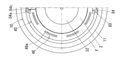
シールリング40の壁部43の内径側端部には、図8A及び図11に示すように、内径側へ突出する凸部44が設けられている。この凸部は、内輪2の外径面に摺接するので、凸部44以外の場所において、壁部43の内径側端部は内輪2の外径面に接触しないようになっている。
図11に示すように、凸部44は転がり軸受21の軸受中心を挟んで対称に配置されている。特に、この実施形態では、シールリング40は周方向に沿って分割された複数の分割シール部材40’が連結片80によって接続されて円環状の連結体となっており、凸部44は、その周方向に隣り合う連結片間の中間地点に備えている。このため、シールリング40は周方向に沿って2箇所に凸部44が設けられている。
ただし、この凸部44の設置数は自由に増減できる。凸部44を、周方向に隣り合う連結片80間を等分方位に分割する地点、例えば、中心角180°の分割シール部材40’に対し、周方向に隣り合う連結片80間の3等分方位の地点に60°の角度を隔てて合計2箇所の凸部44、あるいは、周方向に隣り合う連結片80間の4等分方位の地点に45°の角度を隔てて合計3箇所の凸部44を設けてもよい。ただし、凸部44は、シールリング40の全周を通じて少なくとも2箇所、特に、転がり軸受21の軸受中心を挟んで対称に配置されていることが望ましい。
凸部44を設けたことにより、シールリング40は、凸部44のみが内輪2に摺接して摩耗するが、他の部分は摩耗しないようになる。このため、シールリング40を構成する部材に製造時における公差内の寸法誤差が含まれていても、シールリング40の壁部43の内径側端部と内輪2の外径面との間の最後すきまwは、その凸部44の突出高さw1を下回ることはない。このため、凸部44以外の部分が内輪2に摺接して摩耗することを防止できる。凸部44以外の部分が摩耗しなければ、最後すきまの拡大を回避することができる。また、凸部44が摩耗した際に、その残存する凸部44の突出高さw1を計測すれば、最後すきまの寸法管理が容易である。
また、シールリング40が熱膨張した際にも、凸部44が内輪2の外径面に摺接することで、シールリング40の壁部43の内径側端部と内輪2の外径面との間の最後すきまwは、その凸部44の突出高さw1を下回ることがない。このため、シールリング40の熱膨張の際にも、凸部44以外の部分が内輪2に摺接して摩耗することを防止できる。
また、この実施形態のシールリング40は合成樹脂製であり、特に、内部にグラスファイバを含有する繊維強化樹脂製である。このため、シールリング40を成型する際に、型枠内に未硬化の繊維強化樹脂を充填すると、グラスファイバは、微小な凸部44内には入り込まない。このため、樹脂の硬化によって完成したシールリング40は、凸部44内にはグラスファイバを介在せず、樹脂のみで成型されたものとなる。このため、凸部44が摩耗した際に、グラスファイバの摩耗粉が潤滑油内に入り込むことも防止できる。
凸部44の大きさは、グラスファイバを含有する繊維強化樹脂を型枠内に充填する際、凸部44に対応する型枠内の凹部にグラスファイバが入り込みにくい程度の微小な突出量とすることが望ましい。この実施形態では、最後すきまwは、フィルタ46のメッシュサイズと同じ0.3mmに設定されているので、この凸部44の突出高さw1も0.3mmに設定される。なお、図11に示す、転がり軸受21の軸方向への凸部44の幅w2、転がり軸受の周方向への凸部44の幅w3は、求められる耐摩耗性能に基づいて自由に設定できる。
凸部44の形状は、この実施形態では、転がり軸受の周方向に沿ってその中央で最も高く、そこから周方向両側へ向かうにつれて円弧状に低くなる半円状としているが、この凸部44の形状を、例えば、転がり軸受の周方向に沿ってその中央で最も高く、そこから周方向両側へ向かうにつれて直線的に低くなる三角形状とすることもできる。
また、この実施形態では、凸部44を含むシールシング40の素材を繊維合成樹脂製としているが、内輪2の外径面に当接する凸部44を、耐摩耗性能の高い別の素材としてもよい。例えば、耐摩耗性能の高い合成樹脂や、金属等を採用してもよい。凸部44をシールリング40の本体とは別の素材とする場合、シールリング40の本体とは別部材とした凸部44を含む部材を、嵌め込み固定、接着、溶着等の種々の手法で一体化することができる。
また、図14A、図14Bに示すように、シールリング40の円筒部42に、外輪1の内径面に係合してシールリング40の半径方向への移動を拘束する外輪係止凸部45を備えている。外輪係止凸部45は、外輪1の端面1dと内径面との間の稜線部から、外輪1の軌道面1aへと続く内径面にかけて係合して、シールリング40を拘束している。
このため、シールリング40が熱膨張した際に、外輪係止凸部45の外輪1の内径面への係合により、シールリング40が外径側へ動くことが規制されるので、壁部43の内径側端部と内輪2の外径面との間の最後すきまwが拡大することを防止できる。
この実施形態では、外輪係止凸部45をシールリング40とは別の線膨張係数の低い素材としている。ここでは、外輪係止凸部45を備える着脱部材50を、シールリング40の本体とは別部材として、その部材を、嵌め込み固定、接着、溶着等の種々の手法で一体化している。着脱部材50の素材は、線膨張係数の低い合成樹脂や、金属等を採用してもよい。また、外輪係止凸部45を、シールリング40と一体に形成してもよい。
また、図14Cに示すように、シールリング40の円筒部42に、ハウジング11の内径面に当接してシールリング40の半径方向への移動を拘束するハウジング当接部51を備えている。前述のように、図8Aの例では、連結片80はハウジンク11の内面に係止されているが、シールリング40の本体である円筒部42は、ハウジング11には直接拘束されていなかった。このため、図14Cに示すように、シールリング40の円筒部42に、ハウジング11の内径面に当接してシールリング40の半径方向への移動を拘束するハウジング当接部51を設けたものである。
シールリング40が熱膨張した際に、ハウジング当接部51がハウジング11の内径面へ当接して、シールリング40が外径側へ動くことが規制されるので、壁部43の内径側端部と内輪2の外径面との間の最後すきまwが拡大することを防止できる。
上記の各実施形態において、シールリング40に設けられるフィルタ46の孔46a周辺に、金属粉等の異物の付着を検出するセンサ部を備えてもよい。センサ部としては、例えば、対の電極間に異物が介在することにより、その異物が電極間を短絡した際の電気的出力の変化によって、異物の存在を検知する電気式センサを採用することができる。
例えば、対の電極間に、フィルタ46の孔46aを通過できない大きさの金属からなる異物が付着することに伴って、その対の電極からケーブルを通じて接続された出力検出装置は、対の電極間の異物を介した導通によって、電気回路の電気的出力の変化を検出し、潤滑油に含まれる金属からなる異物の状態(含有量)を検知することができる。対の電極に接続されたケーブルは、基板を経由してハウジング11外に引き出されて、そのケーブルに接続された出力検出装置がいずれかの部分に設けられる。シールリング40外にケーブルを引き出すためのセンサ孔は、シールリング40の円筒部42や壁部43等に設けることができる。
また、上記の実施形態では、シールリング40にフィルタ46を設けたが、フィルタ46を備えないシールリング40においても、この発明の内容を適用できる。また、分割シール部材40’や連結片80を用いた分割型のシールリング40以外にも、分割型ではない一体型の円環状のシールリング40においても、この発明の内容を適用できる。
図15A~図21Cに、この発明の第三の実施形態を示す。図15A~図18に示す装置の基本構成は、同じく前述の第一の実施形態の図1A~図4に対応している。以下の第三の実施形態では、第一の実施形態との共通点の説明は省略し、その差異点を中心に説明する。
この実施形態におけるシールリング40は、連結片80が少なくともシールリング40の下部に位置するように、転がり軸受21の端部に取り付けられる。この実施形態では、中心角180°を成す2つの分割シール部材40’で円環状のシールリング40を構成しているので、連結片80は、シールリング40の上部と下部の2箇所に位置している。ここでは、連結片80は、シールリング40の最上部と最下部にそれぞれ設けられている。
さらに、この実施形態では、シールリング40を2分割として、中心角180°の分割シール部材40’を二つ用いることで円環状のシールリング40を構成しているが、この中心角は180°以外であってもよい。例えば、中心角90°の分割シール部材40’を四つ用いることで円環状のシールリング40を構成してもよいし、中心角60°の分割シール部材40’を六つ用いることで円環状のシールリング40を構成してもよい。
また、シールリング40の壁部43の内径側端部は、内輪2の大つば外径面に摺接するか、または、わずかな隙間を介して対向して、壁部43と内輪2との間にラビリンスシール構造を形成している。ラビリンスシール構造では、潤滑油は通過が許容されるが、潤滑油に含まれる異物の通過は阻止される。壁部43の内径側端部と内輪2の大つば外径面との隙間は、フィルタ46のメッシュサイズと同じか、そのメッシュサイズ以下に設定される。
このように、転がり軸受21,22,23の軸受空間からの潤滑油は、シールリング40に設けたフィルタ46の孔46aや、循環経路12内の孔や隙間、あるいは、壁部43の内径側端部と内輪2の大つば外径面との隙間を通過して、軸受空間外へ流出する。このため、作動機構部30、70の動作に影響が出るような大きな異物(金属からなる摩耗粉の他、特に剥離片等)は、作動機構部30、70側へは侵入しないようになっている。
連結片80には、図19A、図19B、図19Cに示すように、基部81から周方向両側へ伸びる対の支え部85が設けられている。支え部85は、シールリング40の外径面に沿う円筒面状の部材である。各支え部85の先端には、内径側へ突出する係止凸部88が設けられている。この係止凸部88が、周方向に隣り合う分割シール部材40’の端部にそれぞれ設けられた係止孔48に入り込むことで、連結片80は、周方向に隣り合う分割シール部材40’の端部同士を接続する。これにより、分割シール部材40’は円環状の連結体に構成される。
また、分割シール部材40’の端部同士は、図20A、図20Bに示すように、壁部43に設けられ互いに対向するカギ状部47a,47bが噛み合っているので、その接続がより強固となっている。
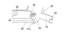
また、連結片80の内面には、凹状の異物捕捉部86が設けられる。異物捕捉部86は、周方向に隣り合う分割シール部材40’の端部にそれぞれ設けられた切欠き49に臨んでいる。このため、異物捕捉部86はシーリング40の内側である軸受空間側に向かって凹状に開放されている。すなわち、シールリング40の下部に位置する連結片80では、異物捕捉部86は軸受空間側に臨む上向きの凹状である。
さらに、異物捕捉部86は、連結片80を挟んで内径側と外径側、すなわち、軸受空間側とその反対側である軸受空間外とを上下方向に貫通する異物排出口87を備える。異物排出口87は、センサ部90に設定された異物捕捉部検出閾値未満の大きさの異物を、軸受空間外へ排出することができる。すなわち、異物排出口87の孔の内径が、センサ部90が検出する対象としている異物の最小径よりも小さく設定されている。
異物捕捉部86は、上向き凹状のポケットであり、特に、この実施形態では、異物捕捉部86の凹部は漏斗状としている。異物排出口87は、その漏斗状の凹部内全体に分布している。
この実施形態では、外輪1は静止側、内輪2は回転側である。内輪2の回転によって、転がり軸受21の軸方向一端側の軸受空間の開口D、及び、循環経路12の軸方向一端側の開口12c、壁部43の内径側端部と内輪2の大つば外径面との隙間から流出した潤滑油は、シールリング40の周方向に沿って流れるようになる。潤滑油に含まれる異物である、転がり軸受21,22,23で生じた金属粉、金属片等のうち、粒径の大きなものはフィルタ46や、循環経路12の開口12cの隙間、壁部43の内径側端部と内輪2の大つば外径面との隙間を通過できず、それらの部分に捕捉されて溜まっていく。
潤滑油に含まれる異物のうち、フィルタ46や各隙間で捕捉されない粒径の小さい異物は、そのまま軸受空間外へ流出する。粒径の小さい異物であれば、その異物が作動機構部30,70へ至っても少量であれば、不具合の原因とはなり得ない。しかし、潤滑油中に含まれる粒径の小さい異物の量が増えてくると、そのまま放置すれば、将来的に不具合に繋がる事態も予想される。このため、転がり軸受21の内輪2の回転が停止した後、粒径の小さな異物がその自重で沈降して異物捕捉部86に溜まった際に、その溜まった異物の量を、センサ部90が検知するようにしている。
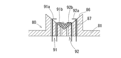
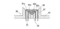
異物捕捉部86に備えられるセンサ部90の詳細を、図21A、図21B、図21Cに示す。センサ部90は、対の電極91,92間への金属からなる異物の付着を電気的に検出するものである。
対の電極91,92間に、異物排出口87を通過できない大きさの金属からなる異物が付着することに伴って、その対の電極91,92からケーブルを通じて接続された出力検出装置94は、対の電極間の異物を介した導通によって、電気回路の電気的出力の変化を検出し、潤滑油に含まれる金属からなる異物の状態(含有量)を検知することができる。対の電極91,92に接続されたケーブルは、連結片80に設けたセンサ孔を通って基板93を経由してハウジング11外に引き出され、そのケーブルに接続された出力検出装置94が、軸受ユニット20のいずれかの部分、又は、軸受ユニット20外に設けられる。なお、基板93はセンサ部90に近い箇所に配置することができ、例えば、連結片80に取り付けることができる。また、センサ孔は異物排出口87を兼用することができる。
対の電極91,92は、異物捕捉部86の凹部内に上下方向に沿って、その電極91,92間隔の異なるものが複数組備えられている。
この実施形態では、異物捕捉部86の内面は外径側へ向かうにつれて狭まる漏斗状となっている。また、複数組の対の電極91,92は、その漏斗状の内面に沿って転がり軸受の内径側から外径側へ向かって、徐々に電極91,92の間隔が小さくなるように設定されている。このため、様々の大きさの異物に対応することができるほか、堆積する異物の量も検知することができる。ここで、異物排出口87の内径が、センサ部90の検出の対象となる異物の下限寸法、すなわち、異物捕捉部検出閾値となる。
すなわち、図21A、図21B、図21Cに示すように、異物排出口87を通過できない大きさの異物は、その大きさに応じて、徐々に狭まる漏斗状の内面間のいずれかの部分に止まるので、確実に電極91,92間を短絡することができる。すなわち、センサ部90は、異物捕捉部検出閾値以上の大きさの異物を効率良く捕捉、検出することができ、電気的出力の変化量からその検出した異物の粒径も把握することができる。
また、センサ部90によれば、潤滑油内への異物の混入量についても把握することができる。例えば、図21A~図21Cにおいて、2組対の電極91a,92a;91b,92bが備えられ、相対的に電極間隔が遠い第一の対の電極91a,92a間と、相対的に電極間隔が近い第二の対の電極91b,92bの両方が異物によって短絡した際には、異物の堆積量が多く、潤滑油内への異物の混入量が多い第一のランクと判定することができる。また、相対的に電極間隔が遠い第一の対の電極91a,92a間が短絡せず、相対的に電極間隔が近い第二の対の電極91b,92b間が異物によって短絡した際には、異物の混入量がより少ない第二のランクと判定することができる。
この実施形態では、異物捕捉部86の内面を、転がり軸受の外径側へ向かうにつれて狭まる漏斗状としたが、この異物捕捉部86の内面形状を、例えば、円筒状等としてもよい。ただし、シールリング40の下部に設けられる異物捕捉部86の内面は、上向き凹状とすることが望ましい。
また、この実施形態では、異物捕捉部86を連結片80の内面に設けたが、シールリング40の下部に設けられる異物捕捉部86は、シールリング40の円筒部42の内面に設けることもできる。特に、連結片80がシールリング40の下部に位置しない場合は、このように円筒部42に異物捕捉部86やセンサ部90を設けることができる。また、分割シール部材40’や連結片80を用いた分割型のシールリング40以外にも、分割型ではない一体型の円環状のシールリング40においても、そのシールリング40の円筒部42に、異物捕捉部86やセンサ部90を設けることができる。
さらに、上記の実施形態では、センサ部90として電気式のセンサを採用したが、これ以外にも、例えば、異物の存在を光によって検知する光学式のセンサを採用してもよい。
上記の各実施形態において、シールリング40に設けられるフィルタ46の孔46a周辺に、金属粉等の異物の付着を検出するセンサ部を備えてもよい。センサ部としては、例えば、対の電極間に異物が介在することにより、その異物が電極間を短絡した際の電気的出力の変化によって、異物の存在を検知する電気式センサを採用することができる。
例えば、対の電極間に、フィルタ46の孔46aを通過できない大きさの金属からなる異物が付着することに伴って、その対の電極からケーブルを通じて接続された出力検出装置は、対の電極間の異物を介した導通によって、電気回路の電気的出力の変化を検出し、潤滑油に含まれる金属からなる異物の状態(含有量)を検知することができる。対の電極に接続されたケーブルは、基板を経由してハウジング11外に引き出されて、そのケーブルに接続された出力検出装置がいずれかの部分に設けられる。シールリング40外にケーブルを引き出すためのセンサ孔は、シールリング40の円筒部42や壁部43等に設けることができる。
上記第一の実施形態における間隔調整手段は、上記第二の実施形態、上記第三の実施形態のそれぞれにおいても適用可能である。また、上記第二の実施形態におけるシール部材の内径側端部に設けられ、内輪の外径面に摺接する凸部は、上記第三の実施形態においても適用可能である。
各実施形態に示されるこの発明のシール部材は、実施形態以外の各種の転がり軸受ユニットにも適用できる。さらに、そのシール部材を備えた転がり軸受ユニットは、オイルポンプ60以外の各種装置にも適用できる。特に、この発明の転がり軸受は、転がり軸受から発生する摩耗粉(鉄粉等)等の異物が、潤滑油の循環経路の途中にある作動機構部70に侵入することを防ぐ必要がある種々の装置に適用できる。
1 外輪(外側軌道輪)
2 内輪(内側軌道輪)
3 転動体
4 保持器
5,6,7 間座
8 押え部材
10 オイルポンプ装置
11 ハウジング
12,13 循環経路
20 軸受ユニット
21,22,23 転がり軸受
30 作動機構部
31 接続部材
32 軸部材
40 シールリング(シール部材)
40’ 分割シール部材
44 凸部
45 外輪係止凸部
46 フィルタ
47a,47b カギ状部
48、48a、48b 係止孔
49 切欠き
50 着脱部材
51 ハウジング当接部
60 オイルポンプ
70 作動機構部
80 連結片
81 基部
82 軸方向部材
83 内径側突出部
84 外径側突出部
85 支え部
86 異物捕捉部
87 異物排出口
88、88a、88b 係止凸部
89 抜け止め用突起
90 センサ部
91,92 電極
2 内輪(内側軌道輪)
3 転動体
4 保持器
5,6,7 間座
8 押え部材
10 オイルポンプ装置
11 ハウジング
12,13 循環経路
20 軸受ユニット
21,22,23 転がり軸受
30 作動機構部
31 接続部材
32 軸部材
40 シールリング(シール部材)
40’ 分割シール部材
44 凸部
45 外輪係止凸部
46 フィルタ
47a,47b カギ状部
48、48a、48b 係止孔
49 切欠き
50 着脱部材
51 ハウジング当接部
60 オイルポンプ
70 作動機構部
80 連結片
81 基部
82 軸方向部材
83 内径側突出部
84 外径側突出部
85 支え部
86 異物捕捉部
87 異物排出口
88、88a、88b 係止凸部
89 抜け止め用突起
90 センサ部
91,92 電極
Claims (19)
- 外輪及び内輪と、
前記外輪と前記内輪との間の軸受空間に配置される転動体と、
前記外輪又は前記外輪に固定された部材に取り付けられて前記軸受空間の側方開口を覆う円環状のシール部材と、
を備え、
前記シール部材は周方向に沿って分割された複数の分割シール部材が連結片によって接続されて円環状の連結体となっており、
周方向に隣り合う前記各分割シール部材と前記連結片との接続部間の周方向への間隔を調整可能とする間隔調整手段を備える
転がり軸受ユニット。 - 前記間隔調整手段は、前記連結片に設けられた係止部と、前記分割シール部材に設けられ前記係止部が係止される被係止部とで構成され、
前記被係止部を前記分割シール部材の周方向端部に周方向に沿って複数備える
請求項1に記載の転がり軸受ユニット。 - 前記間隔調整手段は、前記分割シール部材に設けられた係止部と、前記連結片に設けられ前記係止部が係止される被係止部とで構成され、
前記被係止部を前記連結片に周方向に沿って複数備える
請求項1に記載の転がり軸受ユニット。 - 前記係止部と前記被係止部の一方は凸部であり、他方は一方が嵌合する凹部である
請求項2又は3に記載の転がり軸受ユニット。 - 前記凸部又は前記凹部に、前記凸部が前記凹部から抜け出すのを防止する抜け止め用突起を備える
請求項4に記載の転がり軸受ユニット。 - 前記シール部材は、前記外輪の端面に当接する円筒部と、前記円筒部の筒軸方向一端部から内径側に向かって立ち上がる壁部とを備え、
周方向に隣り合う前記各分割シール部材は、対向する前記壁部又は対向する前記円筒部に互いに噛み合うカギ状部を備える
請求項1~5のいずれか一つに記載の転がり軸受ユニット。 - 前記シール部材は、前記外輪の端面に当接する円筒部と、前記円筒部の筒軸方向一端部から内径側に向かって立ち上がる壁部とを備え、
周方向に隣り合う前記各分割シール部材の対向する前記円筒部の周方向端部間の隙間は、前記連結片によって閉じられる
請求項1~5のいずれか一つに記載の転がり軸受ユニット。 - 外輪及び内輪と、
前記外輪と前記内輪との間の軸受空間に配置される転動体と、
前記外輪又は前記外輪に固定された部材に取り付けられて前記軸受空間の側方開口を覆う円環状のシール部材と、
前記シール部材の内径側端部に設けられ前記内輪の外径面に摺接する凸部と、
を備える転がり軸受ユニット。 - 前記凸部は軸受中心を挟んで対称に配置される
請求項8に記載の転がり軸受ユニット。 - 前記シール部材は周方向に沿って分割された複数の分割シール部材が連結片によって接続されて円環状の連結体となっており、
前記凸部を、周方向に隣り合う前記連結片間を等分方位に分割する地点に備える
請求項8又は9に記載の転がり軸受ユニット。 - 前記シール部材は繊維強化樹脂製である
請求項8~10のいずれか一つに記載の転がり軸受ユニット。 - 前記シール部材は、前記外輪の端面に当接する円筒部と、前記円筒部の筒軸方向一端部から内径側に向かって立ち上がる壁部とを備え、
前記円筒部に前記外輪の内径面に係合してシールリングの半径方向への移動を拘束する外輪係止凸部を備える
請求項8~11のいずれか一つに記載の転がり軸受ユニット。 - 前記外輪はハウジング内に固定され、
前記シール部材は、前記外輪の端面に当接する円筒部と、前記円筒部の筒軸方向一端部から内径側に向かって立ち上がる壁部とを備え、
前記円筒部に前記ハウジングの内径面に当接してシールリングの半径方向への移動を拘束するハウジング当接部を備える
請求項8~12のいずれか一つに記載の転がり軸受ユニット。 - 外輪及び内輪と、
前記外輪と前記内輪との間の軸受空間に配置される転動体と、
前記外輪又は前記内輪のうち静止側の軌道輪若しくはその静止側の軌道輪に固定された部材に取り付けられて前記軸受空間の側方開口を覆う円環状のシール部材と、
前記シール部材の下部に設けられる異物捕捉部と、
前記異物捕捉部に設けられ潤滑油に含まれる異物を検知するセンサ部と、
を備える転がり軸受ユニット。 - 前記シール部材は周方向に沿って分割された複数の分割シール部材が連結片によって接続されて円環状の連結体となっており、
前記異物捕捉部は前記連結片に設けられる
請求項14に記載の転がり軸受ユニット。 - 前記センサ部は、対の電極間への金属からなる異物の付着を電気的に検出する
請求項14又は15に記載の転がり軸受ユニット。 - 前記異物捕捉部は、前記シール部材を挟んで前記軸受空間側とその反対側とを上下方向に貫通する異物排出口を備える
請求項16に記載の転がり軸受ユニット。 - 前記異物捕捉部は上向き凹状のポケットである
請求項17に記載の転がり軸受ユニット。 - 前記異物捕捉部の凹部は漏斗状であり、
前記異物排出口は漏斗状の凹部内に位置し、
前記対の電極は、前記凹部内に上下方向に沿ってその電極間隔の異なるものが複数組備えられる
請求項16~18のいずれか一つに記載の転がり軸受ユニット。
Priority Applications (2)
| Application Number | Priority Date | Filing Date | Title |
|---|---|---|---|
| US16/092,984 US11105374B2 (en) | 2016-04-12 | 2017-04-05 | Rolling bearing unit |
| CN201780023040.XA CN108884875B (zh) | 2016-04-12 | 2017-04-05 | 滚动轴承单元 |
Applications Claiming Priority (6)
| Application Number | Priority Date | Filing Date | Title |
|---|---|---|---|
| JP2016-079632 | 2016-04-12 | ||
| JP2016079635A JP6635861B2 (ja) | 2016-04-12 | 2016-04-12 | 転がり軸受ユニット |
| JP2016-079652 | 2016-04-12 | ||
| JP2016079652A JP6707389B2 (ja) | 2016-04-12 | 2016-04-12 | 転がり軸受ユニット |
| JP2016079632A JP2017190811A (ja) | 2016-04-12 | 2016-04-12 | 転がり軸受ユニット |
| JP2016-079635 | 2016-04-12 |
Publications (1)
| Publication Number | Publication Date |
|---|---|
| WO2017179470A1 true WO2017179470A1 (ja) | 2017-10-19 |
Family
ID=60042079
Family Applications (1)
| Application Number | Title | Priority Date | Filing Date |
|---|---|---|---|
| PCT/JP2017/014256 Ceased WO2017179470A1 (ja) | 2016-04-12 | 2017-04-05 | 転がり軸受ユニット |
Country Status (3)
| Country | Link |
|---|---|
| US (1) | US11105374B2 (ja) |
| CN (1) | CN108884875B (ja) |
| WO (1) | WO2017179470A1 (ja) |
Cited By (1)
| Publication number | Priority date | Publication date | Assignee | Title |
|---|---|---|---|---|
| CN115315581A (zh) * | 2020-02-11 | 2022-11-08 | 利勃海尔比伯拉赫零部件有限公司 | 具有监测装置的滚动轴承 |
Families Citing this family (4)
| Publication number | Priority date | Publication date | Assignee | Title |
|---|---|---|---|---|
| DE102017130335B3 (de) * | 2017-12-18 | 2018-12-27 | Schaeffler Technologies AG & Co. KG | Lageranordnungen und Modulträger für diese |
| DE112020001292T5 (de) * | 2019-03-11 | 2021-12-23 | Ntn Corporation | Wälzlager und sensorbefestigtes wälzlager |
| JP7546059B2 (ja) * | 2020-01-08 | 2024-09-05 | ヴェスタス ウィンド システムズ エー/エス | 風力タービンの主軸受ハウジング |
| CN112610600A (zh) * | 2020-12-14 | 2021-04-06 | 人本股份有限公司 | 可调整游隙的调心滚子轴承 |
Citations (5)
| Publication number | Priority date | Publication date | Assignee | Title |
|---|---|---|---|---|
| JPH04357326A (ja) * | 1991-05-31 | 1992-12-10 | Ntn Corp | 薄肉転がり軸受 |
| JPH0893777A (ja) * | 1994-05-26 | 1996-04-09 | General Electric Co <Ge> | 軸受ハウジング用の環状シール及びロータ軸受ハウジング |
| JP2008241556A (ja) * | 2007-03-28 | 2008-10-09 | Ntn Corp | 潤滑剤劣化検出装置および検出装置付き軸受 |
| JP2010060042A (ja) * | 2008-09-03 | 2010-03-18 | Jtekt Corp | ニードル軸受 |
| JP2014231856A (ja) * | 2013-05-28 | 2014-12-11 | Ntn株式会社 | 転がり軸受 |
Family Cites Families (16)
| Publication number | Priority date | Publication date | Assignee | Title |
|---|---|---|---|---|
| JPS6016083B2 (ja) | 1977-10-31 | 1985-04-23 | キヤノン株式会社 | サーマルヘツド |
| DE3733495A1 (de) * | 1987-10-03 | 1989-04-13 | Skf Gmbh | Eine winkelcodierung aufweisendes lager |
| JPH07280180A (ja) | 1994-04-09 | 1995-10-27 | Sanyo Special Steel Co Ltd | 潤滑油の鉄粉汚濁の検知方法及びその検知センサー |
| US6546785B1 (en) * | 1998-04-02 | 2003-04-15 | Rockwell Automation Technologies, Inc. | System and method for dynamic lubrication adjustment for a lubrication analysis system |
| JP2003097574A (ja) | 2001-09-25 | 2003-04-03 | Koyo Seiko Co Ltd | 転がり軸受 |
| JP4269784B2 (ja) | 2002-12-03 | 2009-05-27 | 日本精工株式会社 | センサ付軸受 |
| JP5578308B2 (ja) * | 2009-07-29 | 2014-08-27 | 大豊工業株式会社 | すべり軸受 |
| EP2483097B2 (en) * | 2009-10-02 | 2023-10-04 | Volvo Lastvagnar AB | A wheel hub unit |
| JP5600555B2 (ja) | 2010-11-08 | 2014-10-01 | Ntn株式会社 | フィルタ付き転がり軸受 |
| CN103477102B (zh) * | 2011-03-22 | 2016-08-17 | Ntn株式会社 | 滚动轴承、以及具备了该滚动轴承的行驶装置 |
| CN202493597U (zh) * | 2012-01-06 | 2012-10-17 | 湖南广绘轴承制造有限公司 | 双列满装密封圈的圆柱滚子轴承 |
| JP2013145028A (ja) * | 2012-01-16 | 2013-07-25 | Nsk Ltd | 密封型転がり軸受 |
| JP6214158B2 (ja) * | 2012-12-28 | 2017-10-18 | Ntn株式会社 | 転がり軸受 |
| CN105229322B (zh) * | 2013-05-28 | 2019-08-16 | Ntn株式会社 | 滚动轴承 |
| WO2015072275A1 (ja) * | 2013-11-12 | 2015-05-21 | イーグル工業株式会社 | 分割型メカニカルシール |
| US20170210166A1 (en) * | 2014-09-11 | 2017-07-27 | Koyo Bearings North America Llc | Axle wheel end axial thrust assembly |
-
2017
- 2017-04-05 US US16/092,984 patent/US11105374B2/en active Active
- 2017-04-05 WO PCT/JP2017/014256 patent/WO2017179470A1/ja not_active Ceased
- 2017-04-05 CN CN201780023040.XA patent/CN108884875B/zh active Active
Patent Citations (5)
| Publication number | Priority date | Publication date | Assignee | Title |
|---|---|---|---|---|
| JPH04357326A (ja) * | 1991-05-31 | 1992-12-10 | Ntn Corp | 薄肉転がり軸受 |
| JPH0893777A (ja) * | 1994-05-26 | 1996-04-09 | General Electric Co <Ge> | 軸受ハウジング用の環状シール及びロータ軸受ハウジング |
| JP2008241556A (ja) * | 2007-03-28 | 2008-10-09 | Ntn Corp | 潤滑剤劣化検出装置および検出装置付き軸受 |
| JP2010060042A (ja) * | 2008-09-03 | 2010-03-18 | Jtekt Corp | ニードル軸受 |
| JP2014231856A (ja) * | 2013-05-28 | 2014-12-11 | Ntn株式会社 | 転がり軸受 |
Cited By (2)
| Publication number | Priority date | Publication date | Assignee | Title |
|---|---|---|---|---|
| CN115315581A (zh) * | 2020-02-11 | 2022-11-08 | 利勃海尔比伯拉赫零部件有限公司 | 具有监测装置的滚动轴承 |
| US12071984B2 (en) | 2020-02-11 | 2024-08-27 | Liebherr-Components Biberach Gmbh | Rolling bearing with monitoring device |
Also Published As
| Publication number | Publication date |
|---|---|
| CN108884875A (zh) | 2018-11-23 |
| CN108884875B (zh) | 2020-06-12 |
| US20200325938A1 (en) | 2020-10-15 |
| US11105374B2 (en) | 2021-08-31 |
Similar Documents
| Publication | Publication Date | Title |
|---|---|---|
| WO2017179470A1 (ja) | 転がり軸受ユニット | |
| CN107923569B (zh) | 滚动轴承的异常检测装置 | |
| CN104884830B (zh) | 滚动轴承 | |
| JP2017190813A (ja) | 転がり軸受ユニット | |
| JP2011058635A (ja) | ユニット化エレメントおよびシールの組み立て方法 | |
| US10883543B2 (en) | Rolling bearing with rotation sensor | |
| JP6581423B2 (ja) | 転がり軸受の異常検知装置 | |
| JP2014231856A (ja) | 転がり軸受 | |
| JP6419478B2 (ja) | 転がり軸受 | |
| WO2018110479A1 (ja) | 転がり軸受の異常検知装置 | |
| JP2017190867A (ja) | 転がり軸受ユニット | |
| JP2016166625A (ja) | フィルタ付転がり軸受 | |
| CN109312782A (zh) | 滚动轴承单元 | |
| JP2017180727A (ja) | 転がり軸受ユニット | |
| JP2017190811A (ja) | 転がり軸受ユニット | |
| JP6685109B2 (ja) | 転がり軸受 | |
| JP6635861B2 (ja) | 転がり軸受ユニット | |
| WO2017179617A1 (ja) | 転がり軸受ユニット | |
| JP2018168994A (ja) | 転がり軸受ユニット | |
| JP6616163B2 (ja) | 転がり軸受 | |
| WO2016133005A1 (ja) | 円すいころ軸受 | |
| WO2017082391A1 (ja) | 転がり軸受ユニット | |
| WO2017213225A1 (ja) | 転がり軸受ユニット | |
| IT202300002274A1 (it) | Unita’ cuscinetto | |
| JP2017057968A (ja) | 転がり軸受 |
Legal Events
| Date | Code | Title | Description |
|---|---|---|---|
| NENP | Non-entry into the national phase |
Ref country code: DE |
|
| 121 | Ep: the epo has been informed by wipo that ep was designated in this application |
Ref document number: 17782287 Country of ref document: EP Kind code of ref document: A1 |
|
| 122 | Ep: pct application non-entry in european phase |
Ref document number: 17782287 Country of ref document: EP Kind code of ref document: A1 |