WO2017179322A1 - バルブタイミング調整装置 - Google Patents
バルブタイミング調整装置 Download PDFInfo
- Publication number
- WO2017179322A1 WO2017179322A1 PCT/JP2017/007584 JP2017007584W WO2017179322A1 WO 2017179322 A1 WO2017179322 A1 WO 2017179322A1 JP 2017007584 W JP2017007584 W JP 2017007584W WO 2017179322 A1 WO2017179322 A1 WO 2017179322A1
- Authority
- WO
- WIPO (PCT)
- Prior art keywords
- driven
- drive
- gear
- rotating body
- stopper wall
- Prior art date
- Legal status (The legal status is an assumption and is not a legal conclusion. Google has not performed a legal analysis and makes no representation as to the accuracy of the status listed.)
- Ceased
Links
Images




Classifications
-
- F—MECHANICAL ENGINEERING; LIGHTING; HEATING; WEAPONS; BLASTING
- F01—MACHINES OR ENGINES IN GENERAL; ENGINE PLANTS IN GENERAL; STEAM ENGINES
- F01L—CYCLICALLY OPERATING VALVES FOR MACHINES OR ENGINES
- F01L1/00—Valve-gear or valve arrangements, e.g. lift-valve gear
- F01L1/34—Valve-gear or valve arrangements, e.g. lift-valve gear characterised by the provision of means for changing the timing of the valves without changing the duration of opening and without affecting the magnitude of the valve lift
- F01L1/344—Valve-gear or valve arrangements, e.g. lift-valve gear characterised by the provision of means for changing the timing of the valves without changing the duration of opening and without affecting the magnitude of the valve lift changing the angular relationship between crankshaft and camshaft, e.g. using helicoidal gear
- F01L1/356—Valve-gear or valve arrangements, e.g. lift-valve gear characterised by the provision of means for changing the timing of the valves without changing the duration of opening and without affecting the magnitude of the valve lift changing the angular relationship between crankshaft and camshaft, e.g. using helicoidal gear making the angular relationship oscillate, e.g. non-homokinetic drive
-
- F—MECHANICAL ENGINEERING; LIGHTING; HEATING; WEAPONS; BLASTING
- F01—MACHINES OR ENGINES IN GENERAL; ENGINE PLANTS IN GENERAL; STEAM ENGINES
- F01L—CYCLICALLY OPERATING VALVES FOR MACHINES OR ENGINES
- F01L1/00—Valve-gear or valve arrangements, e.g. lift-valve gear
- F01L1/34—Valve-gear or valve arrangements, e.g. lift-valve gear characterised by the provision of means for changing the timing of the valves without changing the duration of opening and without affecting the magnitude of the valve lift
- F01L1/344—Valve-gear or valve arrangements, e.g. lift-valve gear characterised by the provision of means for changing the timing of the valves without changing the duration of opening and without affecting the magnitude of the valve lift changing the angular relationship between crankshaft and camshaft, e.g. using helicoidal gear
- F01L1/352—Valve-gear or valve arrangements, e.g. lift-valve gear characterised by the provision of means for changing the timing of the valves without changing the duration of opening and without affecting the magnitude of the valve lift changing the angular relationship between crankshaft and camshaft, e.g. using helicoidal gear using bevel or epicyclic gear
-
- F—MECHANICAL ENGINEERING; LIGHTING; HEATING; WEAPONS; BLASTING
- F01—MACHINES OR ENGINES IN GENERAL; ENGINE PLANTS IN GENERAL; STEAM ENGINES
- F01L—CYCLICALLY OPERATING VALVES FOR MACHINES OR ENGINES
- F01L1/00—Valve-gear or valve arrangements, e.g. lift-valve gear
- F01L1/34—Valve-gear or valve arrangements, e.g. lift-valve gear characterised by the provision of means for changing the timing of the valves without changing the duration of opening and without affecting the magnitude of the valve lift
- F01L1/344—Valve-gear or valve arrangements, e.g. lift-valve gear characterised by the provision of means for changing the timing of the valves without changing the duration of opening and without affecting the magnitude of the valve lift changing the angular relationship between crankshaft and camshaft, e.g. using helicoidal gear
- F01L1/34409—Valve-gear or valve arrangements, e.g. lift-valve gear characterised by the provision of means for changing the timing of the valves without changing the duration of opening and without affecting the magnitude of the valve lift changing the angular relationship between crankshaft and camshaft, e.g. using helicoidal gear by torque-responsive means
-
- F—MECHANICAL ENGINEERING; LIGHTING; HEATING; WEAPONS; BLASTING
- F01—MACHINES OR ENGINES IN GENERAL; ENGINE PLANTS IN GENERAL; STEAM ENGINES
- F01L—CYCLICALLY OPERATING VALVES FOR MACHINES OR ENGINES
- F01L13/00—Modifications of valve-gear to facilitate reversing, braking, starting, changing compression ratio, or other specific operations
- F01L13/0015—Modifications of valve-gear to facilitate reversing, braking, starting, changing compression ratio, or other specific operations for optimising engine performances by modifying valve lift according to various working parameters, e.g. rotational speed, load, torque
-
- F—MECHANICAL ENGINEERING; LIGHTING; HEATING; WEAPONS; BLASTING
- F01—MACHINES OR ENGINES IN GENERAL; ENGINE PLANTS IN GENERAL; STEAM ENGINES
- F01L—CYCLICALLY OPERATING VALVES FOR MACHINES OR ENGINES
- F01L1/00—Valve-gear or valve arrangements, e.g. lift-valve gear
- F01L1/34—Valve-gear or valve arrangements, e.g. lift-valve gear characterised by the provision of means for changing the timing of the valves without changing the duration of opening and without affecting the magnitude of the valve lift
- F01L1/344—Valve-gear or valve arrangements, e.g. lift-valve gear characterised by the provision of means for changing the timing of the valves without changing the duration of opening and without affecting the magnitude of the valve lift changing the angular relationship between crankshaft and camshaft, e.g. using helicoidal gear
- F01L1/352—Valve-gear or valve arrangements, e.g. lift-valve gear characterised by the provision of means for changing the timing of the valves without changing the duration of opening and without affecting the magnitude of the valve lift changing the angular relationship between crankshaft and camshaft, e.g. using helicoidal gear using bevel or epicyclic gear
- F01L2001/3521—Harmonic drive of flexspline type
-
- F—MECHANICAL ENGINEERING; LIGHTING; HEATING; WEAPONS; BLASTING
- F01—MACHINES OR ENGINES IN GENERAL; ENGINE PLANTS IN GENERAL; STEAM ENGINES
- F01L—CYCLICALLY OPERATING VALVES FOR MACHINES OR ENGINES
- F01L2250/00—Camshaft drives characterised by their transmission means
- F01L2250/02—Camshaft drives characterised by their transmission means the camshaft being driven by chains
-
- F—MECHANICAL ENGINEERING; LIGHTING; HEATING; WEAPONS; BLASTING
- F01—MACHINES OR ENGINES IN GENERAL; ENGINE PLANTS IN GENERAL; STEAM ENGINES
- F01L—CYCLICALLY OPERATING VALVES FOR MACHINES OR ENGINES
- F01L2820/00—Details on specific features characterising valve gear arrangements
- F01L2820/03—Auxiliary actuators
- F01L2820/032—Electric motors
Definitions
- This disclosure relates to a valve timing adjusting device that adjusts the valve timing of a valve that opens and closes a camshaft by transmission of crank torque from a crankshaft in an internal combustion engine.
- valve timing adjusting device in which a rotational phase between a rotating body and a driving rotating body and a driven rotating body that rotate in conjunction with a crankshaft and a camshaft change relative to each other is widely known.
- the planetary gear engages with the drive rotator and the driven rotator to make a planetary motion, whereby the rotation phase between the drive rotator and the driven rotator is obtained. Changes. However, the change of the rotation phase is regulated by the contact between the drive-side stopper wall and the driven-side stopper wall of the drive rotator and the driven rotator, respectively.
- a driving rotating body is configured by fastening a gear member and a cover member in an axial direction by a screw which is a fastening member.
- the accommodation space for accommodating the driven rotor and the planetary gear is formed by the joint of the gear member and the cover member.
- the cover member forms a drive-side stopper wall, while the gear member meshes with the planetary gear. Therefore, the driven side stopper wall of the driven rotating body collides with the driving side stopper wall of the cover member to generate a collision torque. There is a concern that the durability and quietness of the apparatus may be reduced due to the collision torque.
- the cover member forms a drive-side stopper wall, while the gear member meshes with the planetary gear. Therefore, the driven side stopper wall of the driven rotating body collides with the driving side stopper wall of the cover member to generate a collision torque. This collision torque is transmitted from the driven rotor to the planetary gear, and further transmitted from the planetary gear to the gear member. Then, relative torque acts between the gear member and the cover member. As a result, the fastening member that fastens the gear member and the cover member in the axial direction is likely to be loosened, which may cause wear and noise at the meshing position between the gear member and the planetary gear inclined by the loosening. was there.
- This disclosure is intended to provide a valve timing adjustment device that ensures durability and quietness.
- the valve timing adjusting device adjusts the valve timing of the valve that opens and closes the camshaft by transmitting the crank torque from the crankshaft in the internal combustion engine.
- the valve timing adjusting device includes a driving rotating body having a driving side stopper wall and rotating in conjunction with the crankshaft.
- the valve timing adjusting device has a driven stopper wall and rotates relative to the drive rotator while rotating in conjunction with the camshaft, thereby changing a rotation phase with the drive rotator.
- a driven rotor that restricts a change in the rotational phase by bringing the driven stopper wall into contact with the drive stopper wall in the relative rotation direction with respect to the drive rotor.
- the valve timing adjusting device further includes a planetary gear that changes the rotational phase by performing planetary movement while meshing with the driving rotating body and the driven rotating body.
- the drive rotor includes a gear member that forms the drive-side stopper wall and meshes with the planetary gear.
- the drive rotator further includes a cover member that covers an accommodation space in which the driven rotator and the planetary gear are accommodated together with the gear member.
- the drive rotator further includes a fastening member that fastens the gear member and the cover member in the axial direction.
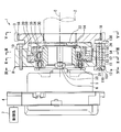
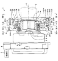
- FIG. 3 is a view showing a valve timing adjusting device according to the first embodiment, and is a cross-sectional view taken along the line II of FIG.
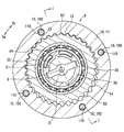
- FIG. 2 is a sectional view taken along line II-II in FIG.
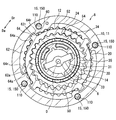
- FIG. 3 is a sectional view taken along line III-III in FIG.
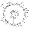
- FIG. 4 is a view taken along the line IV-IV in FIG. It is a VV line arrow view of FIG.
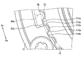
- It is the front view which expands and shows a part of gear member by a first embodiment, It is a front view which expands and shows another part of gear member by a first embodiment, FIG.
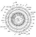
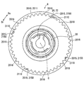
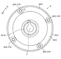
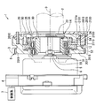
- FIG. 9 is a view showing a valve timing adjusting device according to a second embodiment, and is a sectional view taken along line VIII-VIII in FIG. It is the IX-IX sectional view taken on the line of FIG.
- FIG. 9 is a sectional view taken along line XX of FIG. It is a XI-XI line arrow view of FIG.
- FIG. 9 is a view taken along line XII-XII in FIG. It is sectional drawing which shows the modification of FIG. It is a schematic diagram for demonstrating the conventional subject.
- the valve timing adjusting device 1 As shown in FIG. 1, the valve timing adjusting device 1 according to the first embodiment of the present disclosure is installed in a transmission system that transmits crank torque from a crankshaft (not shown) of an internal combustion engine to a camshaft 2 in a vehicle. Yes.
- the camshaft 2 is a shaft that opens and closes an intake valve (not shown) among the valves in the internal combustion engine by transmitting crank torque. Therefore, the apparatus 1 includes an electric motor 4, a control system 7, a phase adjustment system 8, and the like in order to adjust the valve timing of the intake valve.
- the electric motor 4 is, for example, a brushless motor or the like, and includes a motor case 5 fixed to a fixed node of the internal combustion engine, and a motor shaft 6 supported by the case 5 so as to be rotatable forward and backward.
- the control system 7 includes a drive driver and its control microcomputer, and is disposed outside and / or inside the motor case 5 and is electrically connected to the electric motor 4. The control system 7 controls the energization of the electric motor 4 to generate motor torque and rotationally drive the motor shaft 6.
- the phase adjustment system 8 includes a drive rotator 10, a driven rotator 20, a planet carrier 30, and a planetary gear 50.
- the drive rotator 10 includes a gear member 11 and a cover member 13 and a plurality of fastening members 15 that fasten the two members 11 and 13 coaxially.
- the gear member 11 is formed in a cylindrical shape from metal. As shown in FIGS. 1 to 3, the gear member 11 forms a drive-side internal gear portion 12 having a tooth tip circle set on the inner peripheral side of the root circle.
- a cycloid gear is employed for the drive-side internal gear portion 12 of the present embodiment.
- the cover member 13 is formed of a metal into an annular plate shape.
- the cover member 13 is disposed on the opposite side of the electric motor 4 with the gear member 11 sandwiched in the axial direction.
- the cover member 13 forms a plurality of sprocket teeth 18 projecting from the circumferentially spaced locations to the outer peripheral side.
- the cover member 13 is linked to the crankshaft by spanning the transmission member 3 such as a timing chain between the sprocket teeth 18 and the plurality of teeth of the crankshaft. Under such a connected state, the crank torque of the crankshaft is transmitted to the cover member 13 through the transmission member 3, so that the drive rotor 10 rotates about the rotation center line O in conjunction with the crankshaft.
- the rotational direction of the drive rotor 10 is one side in the circumferential direction (that is, the counterclockwise direction in FIGS. 2 and 3).
- each fastening member 15 is a screw formed of metal.
- Each fastening member 15 is disposed at a location that is eccentric from the rotation center line O of the drive rotator 10 and that is equally spaced in the circumferential direction of the drive rotator 10. That is, the fastening members 15 are arranged substantially parallel along the rotation center line O and at equal intervals around the rotation center line O. Furthermore, each fastening member 15 of this embodiment is shifted from the formation position of the sprocket teeth 18 in the drive rotating body 10 toward the electric motor 4 in the axial direction.
- a male screw part 150 and a head part 151 are integrally provided in each fastening member 15.
- the male screw portion 150 is loosely inserted into a through hole 110 that passes through the gear member 11 in the axial direction.
- the male screw portion 150 is further screwed into a female screw hole 130 that penetrates the cover member 13 in the axial direction.
- a seat surface 151 a shown in FIG. 1 is formed on the head 151 so as to sandwich the gear member 11 with the cover member 13 to which the male screw portion 150 is screwed.
- the gear member 11 and the cover member 13 which are fastened in the axial direction by the respective fastening members 15 jointly cover the accommodating space 14 as shown in FIGS.
- components 20, 30, 50 other than the drive rotator 10 in the phase adjustment system 8 are accommodated.
- the driven rotor 20 is made of metal and has a bottomed cylindrical shape.
- the driven rotator 20 is coaxially fitted to the inner peripheral side of the cover member 13.
- the driven rotating body 20 is formed with a connecting portion 22 coaxially connected to the camshaft 2 on the bottom wall portion as shown in FIGS. Under such a connected state, the driven rotor 20 rotates around the rotation center line O in conjunction with the camshaft 2 by transmission of the crank torque. At this time, the driven rotator 20 can rotate relative to the drive rotator 10 by transmitting the motor torque.
- the rotation direction of the driven rotor 20 that coincides with the rotation direction of the camshaft 2 is one side of the same circumferential direction as the rotation direction of the drive rotor 10 (ie, counterclockwise in FIG. 3).
- the relative rotation direction of the driven rotor 20 with respect to the drive rotor 10 is an advance angle direction Da in which rotation proceeds to one side in the circumferential direction and a retard angle in which rotation is delayed to another side in the circumferential direction.
- the driven rotating body 20 has a driven side internal gear portion 24 having a tooth tip circle set on the inner peripheral side of the root circle on the peripheral wall portion.
- a cycloid gear is employed in the driven side internal gear portion 24 of the present embodiment.
- the number of teeth of the driven side internal gear portion 24 is set to be smaller than the number of teeth of the drive side internal gear portion 12.
- the driven side internal gear portion 24 is displaced toward the cam shaft 2 in the axial direction with respect to the drive side internal gear portion 12.
- the planet carrier 30 is formed of a metal in a partially eccentric cylindrical shape.
- the planetary carrier 30 is disposed in the axial range extending from the inner peripheral side of the driven rotor 20 to the inner peripheral side of the gear member 11 in the accommodation space 14.
- the planetary carrier 30 forms an input portion 31 by a cylindrical inner peripheral surface coaxial with the rotating bodies 10 and 20 and the motor shaft 6.
- the input unit 31 is coupled to the motor shaft 6 through a coupling joint 33 so as to be integrally rotatable. Under such a connected state, the planetary carrier 30 can rotate relative to the drive-side internal gear portion 12 of the drive rotor 10 while rotating around the rotation center line O in conjunction with the motor shaft 6 by transmission of the motor torque.
- the rotation direction of the planetary carrier 30 that coincides with the rotation direction of the motor shaft 6 is the positive rotation direction (that is, the counterclockwise direction in FIGS. 2 and 3) that is one side of the circumferential direction, and the other side of the circumferential direction.
- One of the reverse rotation directions corresponds to the motor torque.
- the relative rotation direction of the planetary carrier 30 with respect to the drive-side internal gear portion 12 is an advance angle direction Da in which the rotation proceeds to one side in the circumferential direction and a delay in which the rotation is delayed to the other side in the circumferential direction.
- the planetary carrier 30 shown in FIGS. 1 to 3 further forms a support portion 34 by a cylindrical outer peripheral surface that is eccentric from the rotating bodies 10 and 20 and the motor shaft 6.
- the support portion 34 is coaxially fitted to the inner peripheral side of the planetary gear 50 via the planetary bearing 35.
- the planetary gear 50 in the fitted state is radially supported by the support portion 34, so that the planetary gear 50 is capable of planetary movement with the relative rotation of the planet carrier 30 with respect to the drive-side internal gear portion 12.
- the planetary motion means a motion in which the planetary gear 50 rotates and revolves in either the forward or reverse rotation direction of the planetary carrier 30.
- the planetary gear 50 is formed of a metal in a stepped cylindrical shape.
- the planetary gear 50 is disposed in an axial range extending from the inner peripheral side of the driven rotor 20 to the inner peripheral side of the gear member 11 in the accommodation space 14.
- the planetary gear 50 forms a drive-side external gear portion 52 and a driven-side external gear portion 54 in which a tooth tip circle is set on the outer peripheral side of the root circle.
- a cycloid gear is employed for the driving side external gear portion 52 and the driven side external gear portion 54 of the present embodiment.
- the number of teeth of the driving side external gear portion 52 and the driven side external gear portion 54 is set to be smaller by the same number than the number of teeth of the driving side internal gear portion 12 and the driven side internal gear portion 24, respectively.
- the drive-side external gear portion 52 is arranged eccentrically on the inner peripheral side of the gear member 11 and is capable of planetary movement while meshing with the drive-side internal gear portion 12.
- the driven side external gear portion 54 is shifted to the cam shaft 2 side in the axial direction with respect to the drive side external gear portion 52.
- the driven-side external gear portion 54 is eccentrically arranged on the inner peripheral side of the driven rotor 20 and is capable of planetary movement while meshing with the driven-side internal gear portion 24.
- the rotational phase between the driving rotating body 10 and the driven rotating body 20 according to the motor torque controlled by the control system 7. (Hereinafter simply referred to as rotational phase) is determined.
- the valve timing of the intake valve is adapted to the operating condition of the internal combustion engine by following such a rotational phase.
- the planetary carrier 30 rotates together with the motor shaft 6 at the same speed as the drive rotator 10, the planetary carrier 30 does not rotate relative to the drive-side internal gear portion 12.
- the planetary gear 50 rotates with the rotating bodies 10 and 20 without planetary motion, so that the rotational phase becomes substantially unchanged and the valve timing is maintained and adjusted.
- the planetary carrier 30 rotates forward at a higher speed than the drive rotator 10 together with the motor shaft 6, the planetary carrier 30 relatively rotates in the advance direction Da with respect to the drive-side internal gear portion 12.
- the planetary gear 50 moves in a planetary motion and the driven rotator 20 rotates relative to the advance direction Da with respect to the drive rotator 10, so that the rotation phase changes and the valve timing is adjusted to advance.
- the planetary carrier 30 rotates together with the motor shaft 6 at a lower speed than the driving rotating body 10 or rotates in the reverse direction, the planetary carrier 30 rotates relative to the driving-side internal gear portion 12 in the retarding direction Dr.
- the planetary gear 50 moves in a planetary motion and the driven rotor 20 rotates relative to the drive rotor 10 in the retard direction Dr, so that the rotation phase is retarded and the valve timing is adjusted.
- the stopper structure 60 is constructed by combining a stopper groove 62 included in the gear member 11 and a stopper protrusion 64 included in the driven rotor 20 in the drive rotor 10.
- the stopper groove 62 is formed in an arcuate groove shape that opens on the inner peripheral side of the gear member 11 and extends along the circumferential direction.
- An inner end face of the stopper groove 62 in the advance angle direction Da forms a drive side advance angle stopper wall 62a.
- An inner end face of the stopper groove 62 in the retard direction Dr forms a drive side retard stopper wall 62r.
- the stopper protrusion 64 is formed in a substantially fan shape that protrudes to the outer peripheral side in the driven rotor 20.
- the stopper protrusion 64 can swing between one side and the other side in the circumferential direction under the state of entering the stopper groove 62.
- a side surface of the stopper projection 64 in the advance angle direction Da forms a driven side advance stopper wall 64a.
- a side surface of the stopper projection 64 in the retarding direction Dr forms a driven side retarding stopper wall 64r.
- the driven rotator 20 has the same direction with respect to the drive rotator 10 by bringing the driven side advance stopper wall 64a into surface contact with the drive side advance stopper wall 62a in the advance direction Da. Relative rotation to Da can be stopped. At this time, the change of the rotational phase is regulated by the most advanced angle phase which is the phase end in the advanced angle direction Da. Accordingly, the driven torque is relatively rotated in the advance direction Da with respect to the drive rotator 10 by the motor torque, and the driven side advance stopper wall 64a collides with the drive side advance stopper wall 62a. appear.
- the driven rotator 20 makes the driven-side retarded stopper wall 64 r in surface contact with the drive-side retarded stopper wall 62 r in the retarded direction Dr so as to be in the same direction with respect to the drive rotator 10. Relative rotation to Dr can be stopped. At this time, the change of the rotational phase is regulated by the most retarded phase which is the phase end of the retarded direction Dr. Therefore, the driven torque 20 is rotated relative to the driving rotation body 10 in the retarding direction Dr by the motor torque, and the driven-side retarding stopper wall 64r collides with the driving-side retarding stopper wall 62r. appear.
- the advance direction Da of the present embodiment is coincident with the proximity direction in which the driven side advance stopper wall 64a is close to the drive side advance stopper wall 62a.
- the advance direction Da as the close direction, the specific tooth bottom portion 111a of the drive-side internal gear portion 12 in the gear member 11 and the specific tooth top portion 112a of the same portion 12 located on the back side of the specific tooth bottom portion 111a.
- the drive side advance stopper wall 62a is formed between the two.
- the drive side advance stopper wall 62a has a diameter straddling between the tooth tip circle Ct passing through the specific tooth top portion 112a and the tooth bottom circle Cb from the outer peripheral side of the tooth bottom circle Cb passing through the specific tooth bottom portion 111a. It is continuous in the direction range. Further, in the advance direction Da, the drive side advance stopper wall 62a is formed so that the specific tooth top portion 112a and the further back tooth are separated from the tooth surface 113a between the specific tooth bottom portion 111a and the specific tooth top portion 112a. It continues in the circumferential direction range straddling to the tooth surface 115a between the bottom 114a. In addition, the drive side advance stopper wall 62a is connected to the drive side internal gear portion 12 in the axial direction.
- the wall of the drive-side advance stopper wall 62a is between the specific tooth bottom portion 111a and the specific tooth top portion 112a to the tooth bottom portion 114a on the back side of the specific tooth top portion 112a. It is possible to ensure a large thickness.
- the retarding direction Dr of the present embodiment coincides with the approaching direction in which the driven-side retarding stopper wall 64r is close to the driving-side retarding stopper wall 62r.
- the retarding direction Dr as the proximity direction, the specific tooth bottom portion 111r of the drive-side internal gear portion 12 in the gear member 11 and the specific tooth top portion 112r of the same portion 12 located on the back side of the specific tooth bottom portion 111r. Between them, a drive side retarding stopper wall 62r is formed.
- the drive-side retarding stopper wall 62r has a diameter straddling between the tooth tip circle Ct passing through the specific tooth top portion 112r and the tooth root circle Cb from the outer peripheral side of the tooth bottom circle Cb passing through the specific tooth bottom portion 111r. It is continuous in the direction range. Further, in the retarding direction Dr, the driving side retarding stopper wall 62r is separated from the tooth surface 113r between the specific tooth bottom portion 111r and the specific tooth top portion 112r, from the specific tooth top portion 112r and further to the back tooth. It is continuing in the circumferential direction range straddling to the tooth surface 115r between the bottom 114r. In addition, the drive side retarding stopper wall 62r is connected to the drive side internal gear portion 12 in the axial direction.
- the drive side advance stopper wall 62a and the drive side retard stopper wall 62r correspond to the “drive side stopper wall”.
- the driven side advance stopper wall 64a and the driven side retard stopper wall 64r correspond to the “driven side stopper wall”.
- the gear member 11 meshing with the planetary gear 50 forms a drive side advance stopper wall 62a and a drive side retard stopper wall 62r. Therefore, the collision torque generated by the collision of the driven side advance stopper wall 64a of the driven side advancement stopper wall 62a of the gear member 11 with the driven side advancement member 20 is transmitted from the driven rotation body 20 to the planetary gear 50, and It is transmitted from the planetary gear 50 to the gear member 11. Thus, the collision torque transmitted to the gear member 11 is received by the driven side advance stopper wall 64a in contact with the drive side advance stopper wall 62a, so that transmission between the gear member 11 and the cover member 13 is suppressed. obtain.
- the collision torque generated by the collision of the driven side retarding stopper wall 64r of the driven rotating body 20 of the gear member 11 with the driven rotating body stopper 20r is transmitted from the driven rotating body 20 to the planetary gear 50. Further, it is transmitted from the planetary gear 50 to the gear member 11.
- the collision torque transmitted to the gear member 11 is received by the driven-side retarded stopper wall 64r in contact with the drive-side retarded stopper wall 62r, so that transmission between the gear member 11 and the cover member 13 is suppressed. obtain.
- each fastening member 15 depends on the collision torque. Is difficult to loosen. Therefore, it is possible to prevent the gear member 11 tilted by the looseness of each fastening member 15 from causing wear and noise at the meshing position with the planetary gear 50, and to ensure durability and quietness.
- a collision torque is generated between the gear member 11 and the cover member 13 that are axially fastened by a plurality of screws that are fastening members 15 that are eccentric from the rotation center line O of the drive rotating body 10.
- the effect of the relative torque caused can be suppressed by the above-described principle. According to this, since the appearance of the arc slip phenomenon can be suppressed on the seating surface 151a of each screw that is in contact with the gear member 11, it is difficult for the screws to loosen. Therefore, it is possible to prevent the gear member 11 inclined due to the looseness of each screw from causing wear and noise at the meshing position with the planetary gear 50, and to ensure durability and quietness.
- the drive side advance stopper wall 64 a is close to the drive side advance stopper wall 62 a.
- the direction Da matches.
- a drive side advance stopper wall 62a is formed between the specific tooth bottom 111a and the back specific tooth top 112a in the gear member 11.
- the wall thickness of the drive side advance stopper wall 62a is between the specific tooth bottom portion 111a and the specific tooth top portion 112a and the tooth bottom portion 114a on the back side of the specific tooth top portion 112a.
- the retard angle is not present in the proximity direction in which the driven side retard stopper wall 64r is close to the drive side retard stopper wall 62r.
- the direction Dr matches.
- a driving side retarding stopper wall 62r is formed between the specific tooth bottom 111r and the back specific tooth top 112r in the gear member 11.
- the thickness of the drive-side retarding stopper wall 62r is between the specific tooth bottom portion 111r and the specific tooth top portion 112r to the tooth bottom portion 114r on the back side of the specific tooth top portion 112r. Can be greatly secured. Therefore, it is possible to prevent damage to the drive side retarding stopper wall 62r caused by the collision torque and to ensure high durability.
- the second embodiment of the present disclosure is a modification of the first embodiment.
- the drive rotating body 2010 of the second embodiment includes a gear member 2011 and a cover member 2013, and a plurality of fastening members 2015 that fasten the two members 2011 and 2013 coaxially, all of which are different from the first embodiment. It has in.
- the metal cover member 2013 is not provided with a plurality of sprocket teeth 18.
- the metal gear member 2011 is provided with a plurality of sprocket teeth 2018 together with the drive-side internal gear portion 12.
- each sprocket tooth 2018 protrudes from the part spaced apart in the circumferential direction in the gear member 2011 to the outer peripheral side.
- the gear member 2011 is linked to the crankshaft by spanning the transmission member 3 between the sprocket teeth 2018 and a plurality of teeth of the crankshaft.
- the crank torque of the crankshaft is transmitted to the gear member 2011 through the transmission member 3, so that the drive rotor 2010 rotates around the rotation center line O in conjunction with the crankshaft.
- the rotation direction of the drive rotator 2010 is one side of the same circumferential direction as that of the first embodiment (that is, the counterclockwise direction in FIGS. 9 and 10).
- each fastening member 2015 is arranged in the drive rotating body 2010 so as to be shifted from the formation position of the sprocket teeth 2018 toward the cam shaft 2 side in the axial direction.
- Each fastening member 2015 is integrally provided with a male screw portion 2150 and a head portion 2151 different from the first embodiment.
- the male screw portion 2150 is loosely inserted into a through hole 2130 penetrating the cover member 2013 in the axial direction opposite to the electric motor 4 with the gear member 2011 interposed therebetween.
- the male screw portion 2150 is further screwed into a female screw hole 2110 that passes through the gear member 2011 in the axial direction.
- a seat surface 2151a shown in FIG. 8 is formed on the head portion 2151 so that the cover member 2013 is sandwiched between the head member 2150 and the gear member 2011 to which the male screw portion 2150 is screwed.
- the second embodiment is the same as the first embodiment except for the configuration described above. Therefore, in the following description, among the effects of the second embodiment, description of the same functions and effects as those of the first embodiment will be omitted, and functions and effects added to the first embodiment will be described.
- crank torque is transmitted from the crankshaft to the gear member 2011 that meshes with the planetary gear 50 in the drive rotor 10 according to the second embodiment.
- the crank torque is transmitted from the gear member 2011 to the planetary gear 50, and further transmitted from the planetary gear 50 to the driven rotor 20 and the camshaft 2, thereby causing the intake valve to be opened and closed by the camshaft 2.
- the action of the relative torque caused by the crank torque can be suppressed between the gear member 2011 and the cover member 2013 that are fastened in the axial direction by each fastening member 2015. Therefore, depending on the crank torque, each fastening member 2015 becomes difficult to loosen.
- each fastening member 2015 is not easily loosened by the collision torque.
- the gear member 2011 tilted by the looseness of each fastening member 2015 can enhance the function of avoiding wear and noise that are brought into engagement with the planetary gear 50, the reliability of the effect of ensuring durability and quietness can be improved. The degree can be improved.
- the cover members 13 and 2013 may be disposed on the opposite side of the cam shaft 2 with the gear members 11 and 2011 sandwiched in the axial direction.
- the cover member 2013 may be formed of resin.
- the modification 2 is based on the fact that the strength of the cover member 2013 is reduced because the action of the relative torque caused by the crank torque and the collision torque can be suppressed between the gear member 2011 and the cover member 2013. Can be adopted.
- a drive side advance stopper wall 62a is formed at a location deviated from between the specific tooth bottom portion 111a and the back specific tooth top portion 112a. It may be.
- a drive side retarded stopper wall 62r is formed at a location deviated from between the specific tooth bottom 111r and the back specific tooth top 112r. It may be.
- a plurality of fastening members 15, 2015 may be arranged at unequal intervals in the circumferential direction.
- the fastening members 15 and 2015 may be rivets or the like other than screws.
- an output shaft of, for example, an electromagnetic brake other than the electric motor 4 may be connected to the input unit 31 of the planetary carrier 30.
- the present disclosure may be applied to a device that adjusts the valve timing of an exhaust valve among the valves of an internal combustion engine.
- the valve timing adjusting device 1 adjusts the valve timing of the valve that opens and closes the camshaft 2 by transmission of crank torque from the crankshaft in the internal combustion engine.
- the valve timing adjusting device 1 includes drive rotators 10, 2010, a driven rotator 20, and a planetary gear 50.
- the drive rotators 10, 2010 have drive side stopper walls 62a, 62r and rotate in conjunction with the crankshaft.
- the driven rotator 20 has driven-side stopper walls 64a and 64r. The driven rotator 20 rotates relative to the drive rotator while rotating in conjunction with the camshaft, whereby the rotation phase with the drive rotator changes.
- the driven rotating body 20 is restricted from changing in rotational phase by bringing the driven stopper wall into contact with the driving stopper wall in the relative rotation directions Da and Dr with respect to the driving rotating body.
- the planetary gear 50 changes the rotation phase by performing planetary movement while meshing with the drive rotator and the driven rotator.
- the drive rotating body includes gear members 11 and 2011, cover members 13 and 2013, and fastening members 15 and 2015.
- the gear members 11 and 2011 form a driving side stopper wall and mesh with the planetary gear.
- the cover members 13 and 2013 cover the accommodation space 14 in which the driven rotor and the planetary gear are accommodated together with the gear member.
- the fastening members 15 and 2015 fasten the gear member and the cover member in the axial direction.
- the gear member engaged with the planetary gear forms a drive side stopper wall. Therefore, the collision torque generated when the driven stopper wall of the driven rotator collides with the driving stopper wall of the gear member is transmitted from the driven rotator to the planetary gear, and further transmitted from the planetary gear to the gear member. The Thus, the collision torque transmitted to the gear member is received by the driven-side stopper wall that is in contact with the driving-side stopper wall, whereby transmission between the gear member and the cover member can be suppressed.
- the fastening member according to the second disclosure is a screw arranged eccentrically from the rotation center line O of the drive rotating body.
- the relative torque caused by the collision torque is generated between the gear member and the cover member that are fastened in the axial direction by the screw that is the fastening member that is eccentric from the rotation center line of the drive rotating body.
Landscapes
- Engineering & Computer Science (AREA)
- Mechanical Engineering (AREA)
- General Engineering & Computer Science (AREA)
- Valve Device For Special Equipments (AREA)
- Retarders (AREA)
Abstract
Description
図1に示すように、本開示の第一実施形態によるバルブタイミング調整装置1は、車両において内燃機関のクランク軸(図示しない)からカム軸2へクランクトルクを伝達する伝達系に、設置されている。ここでカム軸2は、内燃機関における動弁のうち吸気弁(図示しない)を、クランクトルクの伝達により開閉する軸となっている。そこで装置1は、吸気弁のバルブタイミングを調整するために、電動モータ4、制御系7及び位相調整系8等から構成されている。
次に、位相調整系8に設けられるストッパ構造60について、詳細に説明する。
以上説明した第一実施形態の作用効果を、以下に説明する。
図8~12に示すように本開示の第二実施形態は、第一実施形態の変形例である。第二実施形態の駆動回転体2010は、歯車部材2011及びカバー部材2013と、それら二部材2011,2013を同軸上に締結する複数の締結部材2015とを、いずれも第一実施形態とは異なる構成にて有している。
以上、本開示の複数の実施形態について説明したが、本開示は、それらの実施形態に限定して解釈されるものではなく、本開示の要旨を逸脱しない範囲内において種々の実施形態及び組み合わせに適用することができる。
Claims (4)
- 内燃機関においてクランク軸からのクランクトルクの伝達によりカム軸(2)が開閉する動弁のバルブタイミングを調整するバルブタイミング調整装置であって、
駆動側ストッパ壁(62a,62r)を有し、前記クランク軸と連動して回転する駆動回転体(10,2010)と、
従動側ストッパ壁(64a,64r)を有し、前記カム軸(2)と連動して回転しつつ前記駆動回転体(10,2010)に対して相対回転することにより、前記駆動回転体(10,2010)との間の回転位相が変化し、前記駆動回転体(10,2010)に対する相対回転方向(Da,Dr)において前記従動側ストッパ壁(64a,64r)を前記駆動側ストッパ壁(62a,62r)と接触させることにより、前記回転位相の変化が規制される従動回転体(20)と、
前記駆動回転体(10,2010)及び前記従動回転体(20)に噛合しつつ遊星運動することにより、前記回転位相を変化させる遊星歯車(50)とを、備え、
前記駆動回転体(10,2010)は、
前記駆動側ストッパ壁(62a,62r)を形成している共に、前記遊星歯車(50)と噛合している歯車部材(11,2011)と、
前記従動回転体(20)及び前記遊星歯車(50)が収容される収容空間(14)を、前記歯車部材(11,2011)と共同して覆っているカバー部材(13,2013)と、
前記歯車部材(11,2011)と前記カバー部材(13,2013)とを軸方向に締結させている締結部材(15,2015)とを、有するバルブタイミング調整装置。 - 前記締結部材(15,2015)は、前記駆動回転体(10,2010)の回転中心線(O)から偏心して配置されている螺子である請求項1に記載のバルブタイミング調整装置。
- 前記クランク軸から前記歯車部材(11,2011)へ前記クランクトルクが伝達されることにより、前記駆動回転体(10,2010)が前記クランク軸と連動して回転する請求項1又は2に記載のバルブタイミング調整装置。
- 前記相対回転方向(Da,Dr)のうち、前記従動側ストッパ壁(64a,64r)が前記駆動側ストッパ壁(62a,62r)に近接する近接方向(Da,Dr)において、前記歯車部材(11,2011)の特定歯底部(111a,111r)と、前記特定歯底部よりも奥側に位置している前記歯車部材(11,2011)の特定歯頂部(112a,112r)との間に、前記駆動側ストッパ壁(62a,62r)が形成されている請求項1~3のいずれか一項に記載のバルブタイミング調整装置。
Priority Applications (4)
| Application Number | Priority Date | Filing Date | Title |
|---|---|---|---|
| US16/092,583 US10830110B2 (en) | 2016-04-14 | 2017-02-28 | Valve timing adjustment device |
| KR1020187023572A KR102056892B1 (ko) | 2016-04-14 | 2017-02-28 | 밸브타이밍 조정장치 |
| CN201780023291.8A CN109072726B (zh) | 2016-04-14 | 2017-02-28 | 气门正时调整装置 |
| DE112017002023.9T DE112017002023T5 (de) | 2016-04-14 | 2017-02-28 | Ventilsteuerzeiteneinstellvorrichtung |
Applications Claiming Priority (2)
| Application Number | Priority Date | Filing Date | Title |
|---|---|---|---|
| JP2016081459A JP6443382B2 (ja) | 2016-04-14 | 2016-04-14 | バルブタイミング調整装置 |
| JP2016-081459 | 2016-04-14 |
Publications (1)
| Publication Number | Publication Date |
|---|---|
| WO2017179322A1 true WO2017179322A1 (ja) | 2017-10-19 |
Family
ID=60042550
Family Applications (1)
| Application Number | Title | Priority Date | Filing Date |
|---|---|---|---|
| PCT/JP2017/007584 Ceased WO2017179322A1 (ja) | 2016-04-14 | 2017-02-28 | バルブタイミング調整装置 |
Country Status (6)
| Country | Link |
|---|---|
| US (1) | US10830110B2 (ja) |
| JP (1) | JP6443382B2 (ja) |
| KR (1) | KR102056892B1 (ja) |
| CN (1) | CN109072726B (ja) |
| DE (1) | DE112017002023T5 (ja) |
| WO (1) | WO2017179322A1 (ja) |
Families Citing this family (6)
| Publication number | Priority date | Publication date | Assignee | Title |
|---|---|---|---|---|
| TW202500370A (zh) | 2017-09-29 | 2025-01-01 | 日商日東電工股份有限公司 | 積層體、光學構件及光學裝置 |
| JP6911827B2 (ja) * | 2018-09-10 | 2021-07-28 | 株式会社デンソー | バルブタイミング調整装置 |
| JP7161917B2 (ja) * | 2018-10-31 | 2022-10-27 | 株式会社ミクニ | 位相変更ユニット及びバルブタイミング変更装置 |
| JP7226780B2 (ja) * | 2019-03-15 | 2023-02-21 | 株式会社Soken | バルブタイミング調整装置 |
| CN110295964B (zh) * | 2019-05-09 | 2021-03-16 | 湖南大兹动力科技有限公司 | 一种电机调节的内燃机气门控制装置 |
| JP7211302B2 (ja) * | 2019-08-22 | 2023-01-24 | 株式会社デンソー | バルブタイミング調整装置 |
Citations (3)
| Publication number | Priority date | Publication date | Assignee | Title |
|---|---|---|---|---|
| JP2007127107A (ja) * | 2005-11-07 | 2007-05-24 | Toyota Motor Corp | バルブタイミング制御装置 |
| JP2007255412A (ja) * | 2006-02-24 | 2007-10-04 | Denso Corp | バルブタイミング調整装置 |
| JP2015040509A (ja) * | 2013-08-22 | 2015-03-02 | 株式会社デンソー | バルブタイミング調整装置 |
Family Cites Families (9)
| Publication number | Priority date | Publication date | Assignee | Title |
|---|---|---|---|---|
| JP4600379B2 (ja) * | 2006-10-06 | 2010-12-15 | 株式会社デンソー | バルブタイミング調整装置 |
| JP4360426B2 (ja) * | 2007-07-09 | 2009-11-11 | 株式会社デンソー | バルブタイミング調整装置 |
| JP4506817B2 (ja) * | 2007-11-13 | 2010-07-21 | 株式会社デンソー | バルブタイミング調整装置 |
| JP4978627B2 (ja) | 2009-01-08 | 2012-07-18 | 株式会社デンソー | バルブタイミング調整装置 |
| JP5924323B2 (ja) | 2013-09-18 | 2016-05-25 | 株式会社デンソー | バルブタイミング調整装置 |
| JP5862696B2 (ja) | 2014-01-29 | 2016-02-16 | 株式会社日本自動車部品総合研究所 | バルブタイミング調整装置 |
| JP5987868B2 (ja) * | 2014-07-22 | 2016-09-07 | 株式会社デンソー | バルブタイミング調整装置 |
| JP6399587B2 (ja) | 2014-10-22 | 2018-10-03 | シャープ株式会社 | 情報処理装置、情報処理システム、情報処理方法および情報処理プログラム |
| JPWO2016113834A1 (ja) * | 2015-01-13 | 2017-10-19 | 日鍛バルブ株式会社 | 自動車用エンジンの位相可変装置 |
-
2016
- 2016-04-14 JP JP2016081459A patent/JP6443382B2/ja not_active Expired - Fee Related
-
2017
- 2017-02-28 WO PCT/JP2017/007584 patent/WO2017179322A1/ja not_active Ceased
- 2017-02-28 DE DE112017002023.9T patent/DE112017002023T5/de not_active Withdrawn
- 2017-02-28 CN CN201780023291.8A patent/CN109072726B/zh not_active Expired - Fee Related
- 2017-02-28 KR KR1020187023572A patent/KR102056892B1/ko not_active Expired - Fee Related
- 2017-02-28 US US16/092,583 patent/US10830110B2/en not_active Expired - Fee Related
Patent Citations (3)
| Publication number | Priority date | Publication date | Assignee | Title |
|---|---|---|---|---|
| JP2007127107A (ja) * | 2005-11-07 | 2007-05-24 | Toyota Motor Corp | バルブタイミング制御装置 |
| JP2007255412A (ja) * | 2006-02-24 | 2007-10-04 | Denso Corp | バルブタイミング調整装置 |
| JP2015040509A (ja) * | 2013-08-22 | 2015-03-02 | 株式会社デンソー | バルブタイミング調整装置 |
Also Published As
| Publication number | Publication date |
|---|---|
| KR102056892B1 (ko) | 2019-12-17 |
| CN109072726B (zh) | 2020-10-30 |
| DE112017002023T5 (de) | 2019-01-24 |
| JP6443382B2 (ja) | 2018-12-26 |
| JP2017190746A (ja) | 2017-10-19 |
| US10830110B2 (en) | 2020-11-10 |
| KR20180100688A (ko) | 2018-09-11 |
| US20190120091A1 (en) | 2019-04-25 |
| CN109072726A (zh) | 2018-12-21 |
Similar Documents
| Publication | Publication Date | Title |
|---|---|---|
| JP6443382B2 (ja) | バルブタイミング調整装置 | |
| JP6178784B2 (ja) | 同心カムシャフト位相器ねじり駆動機構 | |
| JP4390078B2 (ja) | バルブタイミング調整装置 | |
| JP6350365B2 (ja) | バルブタイミング調整装置、バルブタイミング調整装置の製造に用いられるロック治具、および、バルブタイミング調整装置の製造方法 | |
| CN106460590A (zh) | 阀正时控制装置 | |
| JP2016023591A (ja) | バルブタイミング調整装置 | |
| JP2009185785A (ja) | バルブタイミング調整装置 | |
| US8127729B2 (en) | Valve timing control apparatus | |
| JP5494547B2 (ja) | バルブタイミング調整装置 | |
| JP2009215954A (ja) | バルブタイミング調整装置 | |
| JP2012189050A (ja) | バルブタイミング調整装置 | |
| JP4930427B2 (ja) | バルブタイミング調整装置の製造方法 | |
| JP6314816B2 (ja) | バルブタイミング調整装置 | |
| JP5360111B2 (ja) | バルブタイミング調整装置 | |
| JP2009185786A (ja) | バルブタイミング調整装置 | |
| JP2020125688A (ja) | バルブタイミング調整装置 | |
| JP2015102064A (ja) | 弁開閉時期制御装置 | |
| CN113167140B (zh) | 阀正时调整装置 | |
| JP7131445B2 (ja) | バルブタイミング調整装置 | |
| JP2012237203A (ja) | バルブタイミング調整装置 | |
| JP2009074398A (ja) | バルブタイミング調整装置 | |
| JP5920096B2 (ja) | バルブタイミング調整装置 | |
| WO2020189482A1 (ja) | バルブタイミング調整装置 | |
| WO2020189507A1 (ja) | バルブタイミング調整装置 | |
| JP7294745B2 (ja) | バルブタイミング調整装置 |
Legal Events
| Date | Code | Title | Description |
|---|---|---|---|
| ENP | Entry into the national phase |
Ref document number: 20187023572 Country of ref document: KR Kind code of ref document: A |
|
| WWE | Wipo information: entry into national phase |
Ref document number: 1020187023572 Country of ref document: KR |
|
| 121 | Ep: the epo has been informed by wipo that ep was designated in this application |
Ref document number: 17782140 Country of ref document: EP Kind code of ref document: A1 |
|
| 122 | Ep: pct application non-entry in european phase |
Ref document number: 17782140 Country of ref document: EP Kind code of ref document: A1 |