WO2017175825A1 - Dispositif d'ajustement de position pour volant de direction - Google Patents
Dispositif d'ajustement de position pour volant de direction Download PDFInfo
- Publication number
- WO2017175825A1 WO2017175825A1 PCT/JP2017/014348 JP2017014348W WO2017175825A1 WO 2017175825 A1 WO2017175825 A1 WO 2017175825A1 JP 2017014348 W JP2017014348 W JP 2017014348W WO 2017175825 A1 WO2017175825 A1 WO 2017175825A1
- Authority
- WO
- WIPO (PCT)
- Prior art keywords
- pair
- movable
- engaging portion
- steering wheel
- fixed
- Prior art date
Links
Images


Classifications
-
- B—PERFORMING OPERATIONS; TRANSPORTING
- B62—LAND VEHICLES FOR TRAVELLING OTHERWISE THAN ON RAILS
- B62D—MOTOR VEHICLES; TRAILERS
- B62D1/00—Steering controls, i.e. means for initiating a change of direction of the vehicle
- B62D1/02—Steering controls, i.e. means for initiating a change of direction of the vehicle vehicle-mounted
- B62D1/16—Steering columns
- B62D1/18—Steering columns yieldable or adjustable, e.g. tiltable
- B62D1/184—Mechanisms for locking columns at selected positions
Definitions
- This invention relates to an improvement in a position adjustment device for a steering wheel.
- the steering wheel position adjusting device has a function of adjusting, for example, the front-rear position or the vertical position of a steering wheel for steering an automobile.
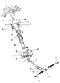
- the automobile steering device is configured as shown in FIG. 9, for example.
- the rotation of the steering wheel 1 is transmitted to the input shaft 3 of the steering gear unit 2, and the pair of left and right tie rods 4, 4 are pushed and pulled along with the rotation of the input shaft 3 to A rudder angle is given to.
- the steering wheel 1 is supported and fixed to the rear end portion of the steering shaft 5.
- the steering shaft 5 is rotatably supported by the steering column 6 in a state where the cylindrical steering column 6 is inserted in the axial direction.
- the front end portion of the steering shaft 5 is connected to the rear end portion of the intermediate shaft 8 via the universal joint 7.
- the front end portion of the intermediate shaft 8 is connected to the input shaft 3 via another universal joint 9.
- the upper front end portion of the housing 10 fixed to the front end portion of the steering column 6 is formed in the width direction with respect to the vehicle body 11 (the width direction is the width direction of the vehicle body,
- the tilt shaft 12 arranged in the left-right direction is the same throughout the present specification and claims).
- a displacement bracket 13 is provided on the lower surface of the intermediate portion of the steering column 6 in the axial direction, and a support bracket 14 is provided with the displacement bracket 13 being sandwiched from both sides in the width direction.
- Each of the pair of left and right support plate portions 22, 22 constituting the support bracket 14 is formed with a long tilt adjustment hole 15 that is long in the vertical direction.
- a telescopic adjustment long hole 16 is formed in a portion of the displacement bracket 13 that is aligned with a part of both the tilt adjustment long holes 15.
- the adjusting rod 17 is inserted in a state where both the tilt adjusting long holes 15 and the telescopic adjusting long holes 16 are inserted in the width direction.
- the steering shaft 5 and the steering column 6 are configured to be extendable and telescopic adjustment long holes 16 are long holes in the front-rear direction. Then, by operating an adjustment lever (not shown) provided at one end of the adjustment rod 17, the force for holding the displacement bracket 13 from both sides in the width direction is adjusted by the support bracket 14, and the position of the steering wheel 1 can be adjusted. (Unlocked state) and a state (locked state) that can be held at the adjusted position are switched.
- the steering column 6 is slidably fitted to the front part of the outer column 18 disposed on the rear side and the rear part of the inner column 19 disposed on the front side so that the entire length can be expanded and contracted.
- the slit 20 is provided in the front part of the outer column 18 made by die-casting a light alloy so that the inner diameter of the front part can be elastically expanded and reduced.
- a pair of left and right sandwiched portions 21 and 21 are provided in a portion sandwiching the slit 20 from both left and right sides, and the displacement bracket 13 is configured by the pair of sandwiched portions 21 and 21.
- the pair of sandwiched portions 21 and 21 are formed with telescopic adjustment long holes 16 and 16 that are long in the front-rear direction.
- a pair of left and right support plate portions 22, 22 provided on the support bracket 14 is disposed in a portion that sandwiches the displacement bracket 13 from both the left and right sides, and tilts to each of the pair of support plate portions 22, 22.
- Tilt adjusting slots 15, 15 are formed in a partial arc shape centering on the shaft 12 (see FIG. 9) and long in the vertical direction. Then, the adjusting rod 17 is inserted in the width direction through both the tilt adjusting long holes 15 and 15 and the both telescopic adjusting long holes 16 and 16.
- An adjusting lever 23 is provided at one end of the adjusting rod 17 in the axial direction (left end in FIG. 11).
- a nut 24 is provided at the other axial end (right end in FIG. 11).
- a thrust bearing 26 and a cam device 57 constituted by a driving side cam 37c and a driven side cam 38c are provided at a portion near one end in the axial direction intermediate portion. Then, based on the swing of the adjustment lever 23, the distance between the inner surfaces of the pair of support plate portions 22, 22 is expanded or reduced.
- the adjustment lever 23 When adjusting the position of the steering wheel 1, the adjustment lever 23 is swung in a predetermined direction (generally downward) to unlock the drive cam 37c, which is the rotation direction when switching to the unlocked state. Rotate in the direction. And the axial direction dimension of the cam apparatus 57 is shrunk
- the surface pressure of the contact portion between the inner surface of the pair of support plate portions 22 and 22 and the outer surface of the pair of sandwiched portions 21 and 21 is reduced or lost, and at the same time, the front end of the outer column 18
- the inner diameter of the portion expands elastically, and the surface pressure of the contact portion between the inner peripheral surface of the front end of the outer column 18 and the outer peripheral surface of the rear end of the inner column 19 decreases.
- the vertical position and the front-rear position of the steering wheel 1 can be adjusted within a range in which the adjustment rod 17 can move in both the tilt adjustment long holes 15 and 15 and the both telescopic adjustment long holes 16 and 16.
- the adjustment lever 23 In order to hold the steering wheel 1 in a desired position, after moving the steering wheel 1 to the desired position, the adjustment lever 23 is swung in the reverse direction (generally upward). Thereby, the drive side cam 37c is rotated in the lock direction which is the rotation direction when switching to the locked state. And the axial direction dimension of the cam apparatus 57 is expanded, and the space
- the steering device having the above-described configuration is configured so that the vertical position of the steering wheel 1 and the position of the steering wheel 1 are reduced by the frictional force acting between the pair of support plate portions 22 and 22 and the pair of sandwiched portions 21 and 21.
- the front-rear position is held at the adjusted position.
- a structure that can hold the position of the steering wheel 1 more firmly is demanded from the viewpoint of enhancing the protection of the driver at the time of a secondary collision or the like.
- the present invention is to realize a structure that can firmly hold the position of the steering wheel in a state in which the vertical position or the front-rear position of the steering wheel can be held at the adjusted position.
- the steering wheel position adjusting device of the present invention includes a displacement bracket, a fixed bracket, an adjusting rod, a pair of pressing portions, and an expansion / contraction device.
- the displacement bracket is fixed to the steering column and has a first through hole.
- the fixed side bracket includes a pair of support plate portions provided in a state where the displacement side bracket is sandwiched from both sides in the width direction, and a pair of second through holes are formed and fixed to the vehicle body side.
- the adjusting rod is provided in a state of being inserted through the first through hole and the pair of second through holes in the width direction.
- the pair of pressing portions are provided at portions protruding from the outer surfaces of the pair of support plate portions at both ends of the adjustment rod.
- the said expansion / contraction apparatus is for expanding / contracting the space
- at least one of the first through hole and the pair of second through holes is an adjustment long hole that is long in a position adjustment direction, which is a direction in which the position of the steering wheel should be adjustable.
- the position adjustment direction is the front-rear direction when the position of the steering wheel is adjusted by a telescopic mechanism, and the vertical direction when the position of the steering wheel is adjusted by a tilt mechanism.
- the steering wheel position adjusting device of the present invention includes a lock mechanism that prevents displacement of the displacement side bracket with respect to the fixed side bracket in the position adjustment direction in the locked state.
- a locking mechanism has a fixed side engaging portion and a movable side locking member.
- the fixed-side engaging portion is provided directly or via another member on the fixed-side bracket or the displacement-side bracket in which the adjustment long hole is formed.
- the movable-side lock member has a movable-side engagement portion that can be frictionally engaged or unevenly engaged with the fixed-side engagement portion, and the position adjustment direction and the central axis of the adjustment rod with respect to the adjustment rod Is supported in a state in which a synchronized displacement is possible with respect to the rotation direction around the axis.
- the movable side locking member rotates in the locking direction, and the fixed side engaging portion and the movable side engaging portion are positioned at the position of the adjusting rod. Friction engagement or uneven engagement is performed to prevent displacement in the adjustment direction.
- the movable side locking member rotates in the unlocking direction, and friction engagement or uneven engagement between the fixed side engaging portion and the movable side engaging portion. Is released.
- the force in the position adjusting direction applied to the adjusting rod in the locked state (for example, when a secondary collision occurs or the driver gets on and off)
- the rotational force in the locking direction may be applied to the movable side locking member based on the impact force acting upon leaning to the steering wheel.
- the fixed side engaging portion and the movable side in the locked state of the movable side locking member in the locked state are thicker in the direction perpendicular to the position adjusting direction as it is farther from the central axis of the adjusting rod with respect to the position adjusting direction (wedge shape), You may comprise so that a wedge effect may be produced between the said fixed side engaging part and the said adjustment rod based on the force of the said position adjustment direction added to the said adjustment rod.
- the movable side lock member is made to have a width of at least one of the pair of support plate portions constituting the fixed side bracket.
- the support plate portion may be arranged in a state in which it is prevented from coming off in the width direction.
- the fixed side engaging portion is formed on a fixed side friction surface (flat surface, flat surface) formed in a state parallel to the position adjusting direction. You may comprise by surface treatment etc.).
- the distance from the central axis of the adjustment rod increases as the movable side engaging portion moves from the position where the movable side engaging portion is frictionally engaged with the fixed side engaging portion in the locked state in the direction opposite to the locking direction. You may comprise like this.
- the fixed side engaging portion is constituted by a first fixed side engaging portion and a second fixed side engaging portion.
- the movable side engaging portion may be constituted by a first movable side engaging portion and a second movable side engaging portion.
- the first movable side engaging portion and the first fixed side engaging portion are engaged, and the second movable side engaging portion and the second fixed side are engaged.
- the movable side lock member has an elastic arm portion, and the movable side lock member is in contact with the adjustment rod.
- a configuration may be adopted in which the elastic arm portion is supported (supported in a state in which relative rotation within the elastic range of the pair of elastic arm portions with respect to the adjustment rod is possible).
- the position of the steering wheel in a state where the vertical position or the front-rear position of the steering wheel can be held at the adjusted position (locked state). Can be held firmly. That is, in the case of the present invention, in the locked state, the fixed side engaging portion provided directly (or indirectly) on the bracket formed with the adjustment long hole of the fixed side bracket or the displacement side bracket, A movable side engaging member of a movable side lock member supported so as to be capable of synchronous displacement in the position adjustment direction with respect to the adjustment rod so as to prevent displacement of the adjustment rod in the position adjustment direction. Engagement (friction engagement or uneven engagement) is performed. Therefore, even when an impact load in the position adjustment direction is applied to the steering wheel in the locked state, the steering wheel can be prevented from being displaced in the position adjustment direction based on the meshing.
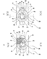
- FIG. 2A is a diagram showing the lock mechanism as viewed from the outside in the width direction, showing the unlocked state
- FIG. 2B is a diagram showing the locked state
- FIG. 3 is a sectional view taken along line AA in FIG.
- FIG. 5A is a view similar to FIG. 2A showing a third example of the embodiment of the present invention
- FIG. 5B is a view similar to FIG. 2B
- FIG. 6A is a diagram similar to FIG. 2A showing a fourth example of the embodiment of the present invention
- FIG. 6B is a diagram similar to FIG. 2B.
- FIG.7 (a) is a figure which shows the state which looked at the locking mechanism from the width direction outer side which shows the 5th example of embodiment of this invention, Comprising: It is a figure which shows an unlocked state, FIG.7 (b) FIG. 4 is a diagram showing a locked state.
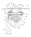
- BB sectional drawing of FIG. The partial side view which shows an example of the conventional structure of a steering device. The partial side view for demonstrating the specific structure of a steering device.
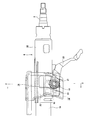
- FIGS. 1 and 2 A first example of an embodiment of the present invention will be described with reference to FIGS.
- the basic structure of the steering device to which the steering wheel position adjusting device of this example can be applied is substantially the same as the structure of the steering device described in FIG. That is, the steering device to which the steering wheel position adjusting device of this example can be applied transmits the rotation of the steering wheel 1 (see FIG. 9) to the input shaft 3 of the steering gear unit 2, and the rotation of the input shaft 3 is accompanied. Then, a pair of left and right tie rods 4 and 4 are pushed and pulled through the rack and pinion mechanism to give a steering angle to the wheels.
- the steering wheel 1 is supported and fixed to the rear end portion of the steering shaft 5.
- the steering shaft 5 is rotatably supported by the steering column 6a with the cylindrical steering column 6a inserted in the axial direction.
- the front end portion of the steering shaft 5 is connected to the rear end portion of the intermediate shaft 8 via a universal joint 7.
- the front end portion of the intermediate shaft 8 is connected to the input shaft 3 via another universal joint 9.
- an electric motor 27 (see FIG. 9) serving as a power source is provided in front of the steering column 6a.
- the steering shaft 5 that supports and fixes the steering wheel 1 at the rear end is formed by a front end of the outer shaft 28 provided on the rear side (right side in FIG. 9) and a rear shaft 29 provided on the front side (left side in FIG. 9).
- the front and rear positions of the outer shaft 28 can be adjusted by spline engagement with the end portions.
- Such a steering shaft 5 is supported on the inside of the steering column 6a by a single row deep groove type ball bearing (not shown) so as to be rotatable only.
- the steering column 6a is slidably fitted to the front part of the outer column 18a arranged on the rear side and the rear part of the inner column 19a arranged on the front side so that the entire length can be expanded and contracted.
- a slit 20a is provided in the front part and upper end part of the outer column 18a made by die-casting a light alloy so that the inner diameter of the front part can be elastically expanded and reduced.
- a pair of left and right sandwiched portions 21a and 21a is provided at a portion sandwiching the slit 20a from both left and right sides, and the pair of sandwiched portions 21a and 21a constitutes a displacement bracket 13a. In such a pair of sandwiched portions 21a, 21a, telescopic adjustment long holes 16a, 16a that are long in the front-rear direction are formed.
- the housing 10 (see FIG. 9) is fixed to the front end of the steering column 6a (inner column 19a).
- the upper front end portion of the housing 10 is supported by a tilt shaft 12 disposed in the width direction with respect to the vehicle body 11 in a state in which the housing 10 can swing in the vertical direction around the tilt shaft 12.
- a worm-type speed reducer including a worm and a worm wheel (not shown) constituting an electric assist mechanism is disposed. Based on the torque acting on the inner shaft 29, the worm is rotationally driven by the electric motor 27 fixed to the housing 10, so that a steering assist force is applied to the steering shaft 5.
- the support bracket 14a is provided with the displacement bracket 13a sandwiched from both sides in the width direction.
- the support bracket 14 a includes a mounting plate portion 30 provided on the upper portion, and a pair of left and right support plate portions 22 a and 22 b that hang downward from the mounting plate portion 30.
- the upper end edges of the pair of support plate portions 22 a and 22 b are continuous by the connecting plate portion 31, and the upper surface of the connecting plate portion 31 is the lower surface of the central portion in the width direction of the mounting plate portion 30. It is fixed by welding.
- Such a support bracket 14a is supported by the mounting plate portion 30 via a pair of release capsules 32, 32 (see FIG. 11) with respect to the vehicle body so that the support bracket 14a can be released forward during a secondary collision.
- the pair of support plate portions 22a and 22b are formed with a pair of tilt adjusting long holes 15a and 15b which are partially arc-shaped around the tilt shaft 12 and are long in the vertical direction.
- the pair of tilt adjusting long holes 15a and 15b can be formed in a rectangular shape that is long in the vertical direction instead of a partial arc shape.
- the pair of telescopic adjustment long holes 16a and 16a corresponds to the first through hole described in the claims, and the pair of tilt adjustment long holes 15a and 15b are described in the claims. It corresponds to the second through hole.
- the pair of tilt adjusting long holes 15a and 15b correspond to the adjusting long holes described in the claims, and the forming direction (vertical direction) of the pair of tilt adjusting long holes 15a and 15b is as follows. This corresponds to the position adjustment direction described in the claims.
- the vertical position of the steering wheel 1 can be adjusted based on the rocking displacement about the tilt shaft 12, and the front and rear of the steering wheel 1 can be adjusted based on the expansion and contraction of the steering shaft 5 and the steering column 6a.
- the position can be adjusted.
- the adjusting rod 17a is inserted in the width direction into the pair of tilt adjusting long holes 15a and 15b and the pair of telescopic adjusting long holes 16a and 16a.
- the adjustment rod 17a includes a male screw portion (not shown) formed at one axial end portion (the right end portion in FIG. 1), a non-circular portion 33 formed at the axial intermediate portion, and the other axial end portion (FIG. 1). And a head portion 34 formed at the left end portion.
- the non-circular portion 33 is formed from a portion of the adjustment rod 17a disposed inside the tilt adjustment long hole 15b of the other (left side in FIG. 1) of the pair of tilt adjustment long holes 15a and 15b.
- the head 34 is provided over a portion adjacent to the inner side surface in the width direction.
- the non-circular portion 33 includes a pair of flat surface portions 35a and 35b formed so as to be cut out in two flat positions parallel to each other on the opposite side with respect to the radial direction of the outer peripheral surface.
- a pair of pressing curved surface portions 36a, 36b formed in a portion between a pair of flat surface portions 35a, 35b with respect to the circumferential direction of the rod 17a and having a cross-sectional arc shape around the central axis of the non-circular portion 33; Have.
- the non-circular portion 33 has a two-fold symmetry (a shape in which the non-circular portion 33 overlaps itself when rotated 180 °).
- the distance between the pair of flat surface portions 35a and 35b is smaller than the distance between the vertices of the pair of pressing curved surface portions 36a and 36b.
- the pair of flat surface portions 35a and 35b is formed by the pair of tilt adjusting long holes 15a and 15b. It arrange
- the non-circular portion 33 can be provided in an arbitrary range of the adjusting rod 17a as long as it includes a portion disposed inside the support hole 50 constituting the movable side lock member 43 described later. For example, a portion other than the male screw portion and the head portion 34 of the adjustment rod 17a can be used as the non-circular portion 33 over the entire length.
- a cylindrical member provided separately from the adjusting rod 17a and having a pair of flat surface portions and a pair of pressing curved surface portions on the outer peripheral surface is externally fitted to the outer peripheral surface of the intermediate portion in the axial direction of the adjusting rod 17a.
- a non-circular part can also be formed by fixing.
- a driven cam 37 and a portion between the head 34 of the adjusting rod 17a and the other support plate 22b of the pair of support plates 22a and 22b (left side in FIG. 1), A driving cam 38, an adjusting lever 23, and a lock mechanism 39 are disposed.
- the driven-side cam 37 together with the driving-side cam 38, constitutes a cam device corresponding to the expansion / contraction mechanism described in the claims.
- the driven cam 37 is made of, for example, sintered metal, has a center hole 58 for inserting the adjusting rod 17a, and has a substantially annular plate shape as a whole. Further, the driven cam 37 has a driven cam surface that is an uneven surface in the circumferential direction on the outer side surface in the width direction (left side surface in FIG. 1). Further, a pair of guide convex portions 60a and 60b are projected inward in the width direction at the front end portion and the rear end portion (two positions separated in the front-rear direction) of the inner surface in the width direction of the driven cam 37. Is formed.
- the distance between the side surfaces facing the front-rear direction of the pair of guide convex portions 60a, 60b is the front side surface and the rear side of the rectangular frame-shaped convex portion 61 formed on the outer side surface in the width direction of the other support plate portion 22b described later. Slightly larger than the distance to the side.
- the driven side cam 37 is in a state in which relative rotation with respect to the adjustment rod 17a is possible with the portion closer to the other end in the axial direction of the adjustment rod 17a being inserted into the center hole 58, and in the width direction (of the adjustment rod 17a). (Axial direction) is externally fitted so that relative displacement is possible.
- One (front) guide convex portion 60a of the pair of guide convex portions 60a and 60b is disposed on the front side of the front frame portion 62 constituting the convex portion 61 having a rectangular frame shape.
- the other (rear) guide convex portion 60b of the pair of guide convex portions 60a and 60b is disposed on the rear side of the rear frame portion 63 constituting the convex portion 61 having a rectangular frame shape.
- the rear side surface of one guide convex portion 60a and the front side surface of the front side frame portion 62 are made to face each other, the front side surface of the other guide convex portion 60b, and the rear side surface of the rear side frame portion 63 , Are close to each other.
- the other support plate portion 22b is engaged with the pair of guide convex portions 60a and 60b, thereby the other side of the driven cam 37.
- An engaging portion capable of preventing rotation with respect to the support plate portion 22b is provided.
- the drive side cam 38 is made of, for example, sintered metal, and has a center hole 59 through which the adjustment rod 17a is inserted, and the entire shape is, for example, an annular plate shape or a rectangular plate shape.
- the inner peripheral surface of the center hole 59 of the drive side cam 38 has a shape capable of non-circular fitting with the outer peripheral surface of the non-circular portion 33 of the adjustment rod 17a.
- a drive side cam surface that is an uneven surface in the circumferential direction is formed on the inner side surface in the width direction of the drive side cam 38 (the right side surface in FIG. 1).
- a driving side engaging convex portion 40 protruding outward in the width direction is provided on the outer side surface of the driving side cam 38 in the width direction.
- Such a drive-side cam 38 has an outer peripheral surface of the other end portion in the axial direction than the portion where the driven-side cam 37 is externally fitted in the center hole 59 near the other end in the axial direction of the adjusting rod 17a ( A part of the non-circular portion 33) is assembled in a non-circular fitting state. Further, in this state, the driving side engaging convex portion 40 is engaged with a lever side through hole 41 provided at the base end portion of the adjusting lever 23. In this way, the drive side cam 38 can rotate integrally with the adjustment lever 23.
- the drive side cam 38 and the adjustment rod 17a can be integrally rotated by press-fitting the axial direction other end portion of the adjustment rod 17a into the center hole 59 of the drive side cam 38.
- the adjustment lever 23, the drive side cam 38, and the adjustment rod 17a are assembled in a state where they can rotate integrally.
- the lock mechanism 39 includes a fixed side tooth portion 42, a movable side lock member 43, and a non-circular portion 33 provided on the adjustment rod 17a. Such a lock mechanism 39 is for preventing the vertical displacement of the adjustment rod 17a in the locked state by the concave-convex engagement.
- the fixed-side tooth portion 42 corresponds to the fixed-side engaging portion described in the claims.
- the fixed-side tooth portion 42 is parallel to the direction (vertical direction) of the other tilt adjustment slot 15b on the outer side surface in the width direction of the other support plate portion 22b.
- the holding force in the vertical direction of the steering wheel 1 can be increased.
- Including a substantially parallel state as much as possible hereinafter, the same, it is constituted by uneven portions formed in the same direction.
- the fixed-side tooth portion 42 can be directly formed on the other support plate portion 22b, or another member (for example, a plate-like member) fixed (for example, welded) to the other support plate portion 22b. Etc.).
- a recess 44 is formed in the widthwise outer side surface of the other support plate portion 22b in the portion adjacent to the other tilt adjustment long hole 15b in the front-rear direction and the vertical direction.
- the concave portion 44 has a substantially rectangular shape that is long in the vertical direction when viewed from the width direction, but is not limited to such a shape.
- the front side surface and the rear side surface of the recess 44 are parallel to the direction in which the other tilt adjusting long hole 15b is formed.
- a fixed-side tooth portion 42 is formed on the front side surface of the recess 44.
- the portion surrounding the other tilt adjusting long hole 15b is pressed on the widthwise inner side surface of the other support plate portion 22b.
- the convex part 61 whose shape seen from the width direction is a rectangular frame shape is formed.
- a portion surrounded by the rectangular frame-shaped convex portion is a concave portion 44.
- the concave portion 44 can be formed by denting a portion surrounding the other tilt adjusting long hole 15b on the outer side surface in the width direction of the other support plate portion 22b from the other portion.
- the fixed-side tooth portion 42 can be formed not on the front side surface of the recess 44 but on the rear side surface.
- the front side portion and the rear side of the other side of the other support plate portion 22b in the width direction than the other long hole 15b for tilt adjustment.
- a pair of vertical protrusions is formed in the portion in a state parallel to the direction in which the other tilt adjusting elongated hole 15b is formed and protruding outward in the width direction, and one of the pair of vertical protrusions
- the fixed-side tooth portion 42 can be formed on the rear side surface of the (front) vertical convex portion (or the front side surface of the other vertical convex portion).
- a pair of vertical projections are formed at both longitudinal ends of a plate-like member provided separately from the other support plate 22b, and one of the pair of vertical projections is one vertical projection.
- the fixed side tooth portion 42 can be formed on the rear side surface (or the front side surface of the other vertical convex portion). When such a configuration is adopted, this plate member is fixed to the other support plate portion 22b by welding.
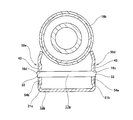
- the movable side lock member 43 is made by stamping an elastic metal plate by pressing, and includes a main body portion 45, a wedge portion 46, a pair of support portions 47a and 47b, and a patent. And a pair of arm portions 48a and 48b corresponding to the pair of elastic arm portions recited in the claims.
- the structure of such a movable side lock member 43 will be described with reference to the assembled state shown in FIG. 2A shows a state in which the position of the steering wheel 1 can be adjusted (unlocked state), and FIG. 2B shows that the vertical position and the front and rear position of the steering wheel 1 are held at the adjusted positions. A possible state (lock state) is shown.
- the main body 45 is configured in a substantially annular shape. Specifically, the main body portion 45 has an outer edge (the outer periphery), a portion indicated by a solid line alpha 1 2 constitutes a and a portion indicated by two-dot chain line beta 1. On the other hand, the main body 45 has an inner edge (inner circumference) constituted by a portion indicated by solid lines ⁇ 2 and ⁇ 3 and a portion indicated by two-dot chain lines ⁇ 2 and ⁇ 3 in FIG.
- the wedge portion 46 has a substantially triangular shape when viewed from the width direction, and a part of the outer peripheral surface of the main body portion 45 in the circumferential direction (at the position of the upper end portion in the unlocked state, in FIG. (part indicated by ⁇ 1 ) is provided in a continuous state.
- a movable side tooth portion 49 composed of a plurality of alternately disposed concave portions and convex portions is provided on the front end surface (left end surface in FIG. 2) of such a wedge portion 46.
- a movable side tooth portion 49 composed of a plurality of alternately disposed concave portions and convex portions is provided.
- Such a wedge portion 46 has a shape in which the thickness dimension in the front-rear direction increases in the locked state as it moves upward (away from the adjustment rod 17a in the vertical direction).
- gear part 49 is corresponded to the movable side engaging part described in the claim.
- the pair of support portions 47a and 47b are provided in a radially projecting state at two positions on the inner peripheral surface of the main body portion 45 that are in the vertical direction in the unlocked state.
- the portion that comes into contact with the non-circular portion 33 in the assembled state becomes radially outward as it goes in one circumferential direction (clockwise in FIG. 2). Inclined in the direction of heading.
- the pair of arm portions 48a and 48b are provided in a state of projecting substantially parallel to the vertical direction in the unlocked state from two radially opposite positions on the inner peripheral surface of the main body 45. .
- one (upper) arm portion 48a of the pair of arm portions 48a and 48b is a circle of the support portion 47a provided above the inner peripheral surface of the main body 45 in the unlocked state. It is provided in a state of extending downward from a portion adjacent to one side in the circumferential direction (clockwise in FIG. 2).
- the other (lower) arm part 48b of the pair of arm parts 48a, 48b is one of the inner peripheral surfaces of the main body part 45 in the circumferential direction of the support part 47b provided below in the unlocked state. It is provided in a state extending upward from a portion adjacent to the side.
- the thickness dimension of the movable side lock member 43 is smaller than the depth dimension (width direction dimension) of the recess 44.
- the portion aligned with the wedge portion 46 (the portion where the movable side tooth portion 49 is formed) in the vertical direction, the movable side tooth portion 49, one support portion 47a, and the non-circular portion 33.
- the portion between the tangent line ⁇ of the contact portion with the one pressing curved surface portion 36a ⁇ the portion indicated by the diagonal lattice in Fig. 2 (b) ⁇ is further away from the central axis of the adjustment rod 17a in the upward direction.
- the wedge-shaped portion 55 having a large thickness dimension in the front-rear direction (which is wedge-shaped) is formed.
- the movable side lock member 43 having the above-described configuration is provided with an adjustment rod in a substantially rectangular support hole 50 defined by a pair of support portions 47a and 47b and a pair of arm portions 48a and 48b.
- the non-circular portion 33 of 17a is inserted, it is arranged inside the concave portion 44 of the other support plate portion 22a.
- the radially inner end surface of one (upper) support portion 47a of the pair of support portions 47a and 47b is one of the pair of pressing curved surface portions 36a and 36b of the non-circular portion 33 (upward).
- the other (lower) support portion 47b are in contact with the other (lower) pressing curved surface portion 36a of the pair of pressing curved surface portions 36a and 36b. ing.
- the rear side surface of the tip end of one (front) arm 48a of the pair of arms 48a and 48b is flat on one (front) of the pair of flat surface portions 35a and 35b of the non-circular portion 33. While elastically contacting along the surface portion 35a, the front side surface of the tip portion of the other (rear) arm portion 48b is also along the other (front) flat surface portion 35a of the pair of flat surface portions 35a and 35b. Are in contact with each other elastically. As a result, the pair of arm portions 48a and 48b can move elastically and far from the pair of flat surface portions 35a and 35b, respectively.
- the movable side lock member 43 is supported in a state in which the adjustment rod 17a can be displaced synchronously in the vertical direction and the rotational direction. In the assembled state, the movable side lock member 43 can be elastically rotated with respect to the adjustment rod 17a within the elastic range of the pair of arm portions 48a and 48b.
- the movable side lock member 43 is disposed in a state of being sandwiched between the width direction outer side surface (the bottom surface of the recess 44) of the other support plate portion 22b and the width direction inner side surface of the driven side cam 37. Yes. In this manner, the movable side lock member 43 is positioned (prevented from coming off) in the width direction. However, the thickness dimension of the movable side lock member 43 is smaller than the depth dimension of the recess 44.
- the width direction outer side surface of this movable side lock member 43 and the width direction inner side surface of the driven side cam 37, the width direction inner side surface of this movable side lock member 43, and the other support A slight gap in the width direction can be present between at least one of the width direction outer side surface of the plate portion 22b (the bottom surface of the concave portion 44) and the portion between the width direction.
- the movable side lock member 43 is not strongly clamped by the outer side surface in the width direction of the other support plate portion 22 b (the bottom surface of the recess 44) and the inner side surface in the width direction of the driven side cam 37.
- the adjustment lever 23 in a state in which the position of the steering wheel 1 can be adjusted (unlocked state) It is swung in a predetermined direction (generally upward, hereinafter referred to as a lock direction).
- a lock direction generally upward, hereinafter referred to as a lock direction
- the movable side lock member 43 is supported so as to be elastically rotatable with respect to the adjustment rod 17a within the elastic range of the pair of arm portions 48a and 48b. Even when the tip of the convex portion of the side tooth portion 49 and the tip of the convex portion of the fixed side tooth portion 42 are in contact with each other and are not normally meshed, the movable side lock member 43 is elastically displaced from this state. Accordingly, the movable side tooth portion 49 and the fixed side tooth portion 42 can be normally meshed with each other.
- the movable side lock member 43 has a rotational force in the locking direction based on the elasticity of the pair of arm portions 48a and 48b. Further, a wedge effect is generated between the fixed side tooth portion 42 and the one pressing curved surface portion 36 a and the wedge-shaped portion 55, and the movable side tooth portion 49 is strongly pressed against the fixed side tooth portion 42.
- the portion of the non-circular portion 33 that contacts one pressing curved surface portion 36a is one in the circumferential direction ⁇ FIG. 2 (b). As it goes forward in the clockwise direction ⁇ , it is inclined upward.
- the portion of the non-circular portion 33 that comes into contact with one pressing curved surface portion 36b is inclined downward in the circumferential direction. .
- the adjustment lever 23 When switching from the locked state to the unlocked state, the adjustment lever 23 is swung in the direction opposite to the predetermined direction (generally downward), thereby reducing the axial dimension of the cam device, so that the driven side The interval between the cam 37 and the pressing plate 25 is increased. Thereby, each friction force becomes small.
- the adjustment lever 23 swings, the movable side lock member 43 together with the adjustment rod 17a rotates in the unlocking direction as shown in FIG. 2A from the state shown in FIG. Then, the meshing (concave engagement) between the fixed side tooth portion 42 and the movable side tooth portion 49 is released.
- the position of the steering wheel 1 can be adjusted within a range in which the adjustment rod 17a can be displaced inside the pair of tilt adjustment long holes 15a and 15b and the pair of telescopic adjustment long holes 16a and 16b. It becomes a state.
- the position of the steering wheel in the vertical direction can be firmly held in a state where the steering wheel can be held at the adjusted position (locked state). That is, in the case of this example, in the locked state, the fixed side tooth portion 42 provided on the other support plate portion 22b of the support bracket 14a fixed to the vehicle body, and the movable side tooth portion 49 of the movable side lock member 43. And are meshed. Such a movable side lock member 43 is supported so as to be able to be displaced in synchronization with the adjustment rod 17a in the vertical direction.
- the steering wheel 1 is caused by a large holding force based on the engagement between the fixed side tooth portion 42 and the movable side tooth portion 49. Can be prevented from being displaced in the vertical direction (for example, jumping up).
- the position of the airbag inflated behind the steering wheel 1 can be maintained at an appropriate position, and the driver can be easily enhanced by this airbag.
- the steering wheel 1 is displaced downward. Can be prevented.
- the portion of the inner peripheral surface of the one (upper) support portion 47a that is in contact with one pressing curved surface portion 36a of the non-circular portion 33 is the one in the circumferential direction ( It is inclined in the upward direction as it goes in the clockwise direction in FIG.
- the adjustment rod 17a steerering wheel 1
- the one pressing curved surface portion 36a is moved to the movable side based on the force pressing the one (upper) supporting portion 47a upward.
- a rotational force in the locking direction acts on the locking member 43.
- the lock mechanism 39 can be provided only on the other support plate portion 22b (right side in FIG. 1) of the pair of support plate portions 22a and 22b. It can also be provided on both of the pair of support plate portions 22a and 22b. In the case of adopting such a configuration, as the structure of the lock mechanism provided on the other support plate portion 22b side, for example, a structure symmetric with respect to the lock mechanism 39 in the width direction can be employed.
- the shape seen from the width direction at the portion adjacent to the front and rear direction and the vertical direction of the other tilt adjusting long hole 15b on the inner surface in the width direction of the other support plate portion 22c. Forms a substantially rectangular recess 44a that is long in the vertical direction.
- gear part 42 (refer FIG. 2) is formed in the front side surface edge (or rear side edge) of this recessed part 44a.
- the structure of the movable side lock member 43 (see FIG. 2 for the detailed structure) constituting the lock mechanism 39a is the same as the first example of the above-described embodiment.
- the movable side lock member 43 is in a state in which the non-circular portion 33 of the adjustment rod 17a is inserted into the support hole 50 defined by the pair of support portions 47a and 47b and the pair of arm portions 48a and 48b. Are disposed inside the recess 44a.
- the movable side lock member 43 has the width in the width direction inner side surface (the bottom surface of the recess 44a) of the other support plate portion 22c and the other sandwiched portion 21a of the pair of sandwiched portions 21a and 21a. It arrange
- the thickness dimension of the movable side lock member 43 is made smaller than the depth dimension of the recess 44a, the outer side surface in the width direction of the movable side lock member 43 and the other support plate part 22b.
- a slight gap in the width direction between the inner surface in the width direction (the bottom surface of the recess 44a) or between the inner surface in the width direction of the movable side lock member 43 and the outer surface in the width direction of the other sandwiched portion 21a. Can exist.
- the movable side lock member 43 is not sandwiched between the width direction inner side surface (the bottom surface of the recess 44) of the other support plate portion 22c and the width direction outer side surface of the one sandwiched portion 21a.
- the rotation of the driven cam 37a is prevented by disposing it at the radially inner end of the inner side surface in the width direction of the driven cam 37a inside the other tilt adjusting slot 15b.
- a guide projection 56 for guiding the displacement in the vertical direction is formed.
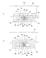
- a third example of the embodiment of the present invention will be described with reference to FIG.
- a recess 44b is formed in a portion adjacent in the vertical direction.
- the recess 44b has a substantially rectangular shape as viewed from the width direction and is long in the vertical direction, and the front side surface and the rear side surface are formed in a state parallel to the direction in which the other tilt adjusting long hole 15b is formed.
- gear part 42 is formed in the front side surface of the recessed part 44b
- gear part 51 is formed in the rear side surface of the recessed part 44b.
- the fixed side tooth portion 42 and the second fixed side tooth portion 51 correspond to the fixed side engaging portion described in the claims.
- the lock mechanism 39b includes a pair of movable side lock members 43 and 43.
- the pair of movable side lock members 43, 43 members having the same shape are used.
- one of the pair of movable side members 43, 43 (inner side in the width direction, back side in FIG. 5) is the same as the first and second examples of the above-described embodiment.
- the movable side tooth portion 49 is arranged so as to mesh with the fixed side tooth portion 42 formed on the front side surface of the recess 44b).
- the other of the pair of movable side lock members 43, 43 (outside in the width direction, front side in FIG.
- the pair of movable side lock members 43 and 43 having the above-described configuration are respectively formed in the support holes 50 defined by the pair of support portions 47a and 47b and the pair of arm portions 48a and 48b. In a state where the non-circular portion 33 of the adjusting rod 17a is inserted, it is disposed inside the concave portion 44b of the other support plate portion 22a. In this manner, the pair of movable side lock members 43 and 43 are supported by the adjustment rod 17a in a state in which synchronized displacement in the vertical direction and the rotation direction is possible.
- the sum of the thickness dimensions of the pair of movable side lock members 43, 43 is made smaller than the depth dimension (width direction dimension) of the recess 44b. Therefore, even in the locked state, the widthwise inner side surface of the other movable side locking member 43 is between the widthwise outer side surface of the other movable side locking member 43 and the widthwise inner side surface of the driven cam 37. Or the widthwise outer side surface of one movable side locking member 43, or the widthwise inner side surface of the one movable side locking member 43 and the widthwise outer side surface of the other support plate portion 22b (the bottom surface of the recess 44b). A slight gap in the width direction can exist between the two.
- the pair of movable side locking members 43 and 43 are strongly sandwiched between the outer side surface in the width direction of the other support plate portion 22b (the bottom surface of the recess 44b) and the inner side surface in the width direction of the driven cam 37. There is nothing to do.
- the vertical position of the steering wheel 1 in the locked state is engaged with the fixed-side tooth portion 42 and the movable-side tooth portion 49 of one movable-side lock member 43, and Based on the meshing between the second fixed side tooth portion 51 and the movable side tooth portion 49 of the other movable side lock member 43, the second fixed side tooth portion 51 is fixed more firmly than the structure of the first example of the above-described embodiment. Can do.
- the adjusting rod 17a (steering wheel 1) If it is to be displaced downward, a wedge effect is generated between the second pressing curved surface portion 36b of the second fixed side tooth portion 51 and the non-circular portion 33 and the wedge-shaped portion 55 of the other movable side locking member 43, The adjustment rod 17a (steering wheel 1) becomes a resistance against a downward displacement.
- the fixed-side friction surface 52 is not only formed into a flat surface but also can be subjected to a surface treatment for increasing the friction coefficient.
- a surface treatment for example, roughening (shot blasting, knurling, etc.) is performed to increase the surface roughness of the fixed-side friction surface 52, or the fixed-side friction surface 52 is coated with a friction agent. You can also.
- the friction agent is not particularly limited as long as the friction coefficient of the surface of the fixed friction surface 52 can be increased.
- the movable side friction member 53 is provided on the movable side lock member 43a in place of the movable side tooth portion 49 of the movable side lock member 43 of the first example of the embodiment described above.
- the movable friction surface 53 corresponds to the movable engagement portion described in the claims.
- the friction angle ⁇ is provided at the friction engagement portion (position X 1 ) between the fixed side friction surface 52 and the movable side friction surface 53.
- the movable friction surface 53 can be formed of a smooth curved surface, or a surface treatment for increasing the friction coefficient can be performed on the surface.
- the surface treatment the same treatment as that for the fixed friction surface 52 can be adopted.
- the member on which the fixed friction surface 52 is formed (in this case, the other support plate portion 22b) and the member on which the movable friction surface 53 is formed (in this case, the movable side lock member). 43a) are made of an iron-based alloy such as carbon steel.
- the member (support bracket 14a) on which the fixed friction surface 52 is formed is made of a metal material having a lower hardness than the metal material constituting the member (movable side lock member 43a) on which the movable side friction surface 53 is formed.
- the other support plate portion 22b is made of an aluminum alloy
- the movable side lock member 43a is made of an iron-based alloy such as carbon steel.
- the fixed friction surface 52 is separate from the other support plate portion 22b and is fixed to the other support plate portion 22b (for example, by welding or the like) (for example, a plate-like member or the like).
- the other support plate portion 22b may be made of an iron-based alloy such as carbon steel, and only the other members may be made of an aluminum alloy. If such a structure is employ
- a movable side tooth portion 49 as in the first example of the embodiment described above can be formed. If such a structure is employ
- a structure in which a pair of movable side lock members are combined in a state where the phases are shifted by 180 ° may be employed.
- fixed side friction surfaces are provided on both front and rear side surfaces of the recess 44c.
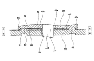
- FIGS. 11 A fifth example of the embodiment of the present invention will be described with reference to FIGS.
- This example shows the structure of a steering wheel position adjusting device provided with a locking mechanism for strengthening the holding force of the steering wheel 1 in the front-rear direction position in the locked state.
- a sufficient amount is provided at the front end portion of the outer column 18b between the pair of support plate portions 22a and 22b of the support bracket 14a (see FIG. 11).
- a displacement bracket 13b having a substantially U-shaped cross section formed by bending a rigid metal plate is fixed by welding or the like.
- telescopic adjustment through holes 16c and 16d extending in the axial direction (front-rear direction) are formed in each of the pair of sandwiched portions 21b and 21c constituting the displacement bracket 13b.
- the telescopic adjustment through holes 16c and 16d correspond to the adjustment long holes described in the claims, and the front-rear direction corresponds to the position adjustment direction.
- recesses 54a and 54b that are long in the front-rear direction are formed in the portions adjacent to the telescopic adjustment through-hole 16d in the front-rear direction and the vertical direction.
- lock mechanisms 39d and 39e are provided for each pair of sandwiched portions 21b and 21c.
- the lock mechanism 39d provided in one (right side) of the pair of sandwiched portions 21b and 21c (right side) will be described.
- the structure of the lock mechanism 39e provided in the other sandwiched portion 21c of the pair of sandwiched portions 21b and 21c is the same as the lock mechanism 39d provided in the one sandwiched portion 21b. Since there is, explanation is omitted.
- the lock mechanism 39d includes a fixed side tooth portion 42a, a movable side lock member 43, and a non-circular portion 33 provided on the adjustment rod 17a.
- the fixed-side tooth portion 42a is provided on the outer surface in the width direction of one of the sandwiched portions 21b, and each of the fixed-side tooth portions 42a is configured by a concavo-convex portion formed in the formation direction (vertical direction) of the telescopic adjustment through hole 16d. Has been.
- the fixed-side tooth portion 42a is formed on the lower surface of the concave portion 54a formed in one (right) sandwiched portion 21b.
- a fixed-side tooth portion 42a is formed on the upper side surface of the lower frame portion that forms a rectangular frame-like frame member that is provided in a separate body from the one sandwiched portion 21b.
- the structure which fixes this frame member inside the recessed part 54a is also employable.
- the movable side locking member 43 has the same structure as the movable side locking member 43 of the first example of the embodiment described above, and is rotated about 90 ° rearward with respect to the arrangement mode of the first example of this embodiment. It arrange
- Such a movable side lock member 43 is inserted through the non-circular portion 33 of the adjusting rod 17a into the support hole 50 defined by the pair of support portions 47a and 47b and the pair of arm portions 48a and 48b. In this state, it is arranged inside the concave portion 54a of the other support plate portion 22a.
- the adjustment rod 17a is disposed inside the movable lock member 43 of the one lock mechanism 39d and inside the movable lock member 43 of the other lock mechanism 39e.
- Non-circular portions 33 and 33 are provided in the portion.
- Such a non-circular portion 33 may be formed in a continuous state in the axial direction of the adjusting rod 17a, or may be formed in a separated state.
- the front-rear direction position of the steering wheel 1 in the locked state can be firmly fixed by the concave-convex engagement between the fixed side tooth portion 42a and the movable side tooth portion 49. .
- the position of the steering wheel 1 can be firmly held when a large impact force in the front-rear direction acts on the steering wheel 1 in the locked state.
- the structure of this example is combined with a pair of movable side locking members shifted by 180 ° as in the third example of the embodiment described above, or as in the fourth example of the embodiment.
- a structure in which the fixed and movable friction surfaces are frictionally engaged can be applied.
- a structure in which a lock mechanism is provided only in one of the pair of sandwiched portions 21b and 21c (a structure in which any one of the lock mechanisms 39d and 39e is omitted) Can also be adopted.
- the present invention is not only a structure having both a tilt mechanism for adjusting the vertical position of the steering wheel and a telescopic mechanism for adjusting the front-rear position, but also a tilt mechanism only or a telescopic mechanism only. It can also be applied to structures with
- the displacement bracket can adopt either a structure provided below the outer column or a structure provided above the outer column.
- the expansion / contraction mechanism may employ not only a cam device but also a screw type structure that adjusts the tightening amount of the adjustment nut screwed to the male screw portion provided on the adjustment rod based on the swing of the adjustment lever. it can.
Landscapes
- Engineering & Computer Science (AREA)
- Chemical & Material Sciences (AREA)
- Combustion & Propulsion (AREA)
- Transportation (AREA)
- Mechanical Engineering (AREA)
- Steering Controls (AREA)
Abstract
Priority Applications (4)
| Application Number | Priority Date | Filing Date | Title |
|---|---|---|---|
| US16/088,715 US20190111962A1 (en) | 2016-04-08 | 2017-04-06 | Position adjustment device for steering wheel |
| CN201780020291.2A CN109070927A (zh) | 2016-04-08 | 2017-04-06 | 方向盘的位置调节装置 |
| JP2018510657A JP6658872B2 (ja) | 2016-04-08 | 2017-04-06 | ステアリングホイールの位置調節装置 |
| EP17779203.3A EP3421326A4 (fr) | 2016-04-08 | 2017-04-06 | Dispositif d'ajustement de position pour volant de direction |
Applications Claiming Priority (2)
| Application Number | Priority Date | Filing Date | Title |
|---|---|---|---|
| JP2016-078330 | 2016-04-08 | ||
| JP2016078330 | 2016-04-08 |
Publications (1)
| Publication Number | Publication Date |
|---|---|
| WO2017175825A1 true WO2017175825A1 (fr) | 2017-10-12 |
Family
ID=60000380
Family Applications (1)
| Application Number | Title | Priority Date | Filing Date |
|---|---|---|---|
| PCT/JP2017/014348 WO2017175825A1 (fr) | 2016-04-08 | 2017-04-06 | Dispositif d'ajustement de position pour volant de direction |
Country Status (5)
| Country | Link |
|---|---|
| US (1) | US20190111962A1 (fr) |
| EP (1) | EP3421326A4 (fr) |
| JP (1) | JP6658872B2 (fr) |
| CN (1) | CN109070927A (fr) |
| WO (1) | WO2017175825A1 (fr) |
Cited By (1)
| Publication number | Priority date | Publication date | Assignee | Title |
|---|---|---|---|---|
| US20220065287A1 (en) * | 2020-08-27 | 2022-03-03 | Zf Automotive Germany Gmbh | Bearing unit for fastening a steering column in a vehicle |
Families Citing this family (4)
| Publication number | Priority date | Publication date | Assignee | Title |
|---|---|---|---|---|
| JP7104881B2 (ja) * | 2018-05-08 | 2022-07-22 | 株式会社ジェイテクト | ステアリング装置 |
| JP7428980B2 (ja) | 2019-05-31 | 2024-02-07 | 日本精工株式会社 | ステアリングコラムポジティブロック駆動機構 |
| CN110450977B (zh) * | 2019-09-16 | 2024-05-14 | 深圳市科卫泰实业发展有限公司 | 一种无人机动态测试装置 |
| US11820422B2 (en) * | 2020-03-03 | 2023-11-21 | Steering Solutions Ip Holding Corporation | Rake lock mechanism for steering column |
Citations (4)
| Publication number | Priority date | Publication date | Assignee | Title |
|---|---|---|---|---|
| JPH07117686A (ja) * | 1993-10-29 | 1995-05-09 | Fuji Kiko Co Ltd | エネルギー吸収ステアリング装置 |
| US20060082119A1 (en) * | 2004-10-14 | 2006-04-20 | Tinnin Melvin L | Lock for tilting and telescoping steering column |
| JP2009090894A (ja) * | 2007-10-10 | 2009-04-30 | Nsk Ltd | ステアリング装置 |
| JP2009227181A (ja) | 2008-03-25 | 2009-10-08 | Nsk Ltd | ステアリング装置 |
Family Cites Families (52)
| Publication number | Priority date | Publication date | Assignee | Title |
|---|---|---|---|---|
| US4938093A (en) * | 1989-03-10 | 1990-07-03 | Nippon Seiko Kabushiki Kaisha | Tilt steering column unit for vehicles with memory mechanism |
| EP0673825B1 (fr) * | 1994-03-18 | 2004-04-07 | Dr.Ing.h.c. F. Porsche Aktiengesellschaft | Appareil de direction réglable |
| US5722299A (en) * | 1994-06-30 | 1998-03-03 | Fuji Kiko Co., Ltd. | Adjustable steering column assembly for a vehicle |
| US5570610A (en) * | 1995-06-30 | 1996-11-05 | General Motors Corporation | Adjustable steering column |
| FR2737172B1 (fr) * | 1995-07-26 | 1997-10-10 | Nacam | Systeme de guidage et de verrouillage pour colonne de direction de vehicules automobile |
| JPH09142311A (ja) * | 1995-11-24 | 1997-06-03 | Tokai Rika Co Ltd | エアバッグを備えたステアリング装置 |
| GB2311839A (en) * | 1996-04-02 | 1997-10-08 | Nastech Europ Ltd | A reach and rake adjustable steering column device |
| FR2768205B1 (fr) * | 1997-09-05 | 1999-10-29 | Lemforder Nacam Sa | Securite d'engagement a etrier d'un dispositif de maintien en position d'un systeme de serrage de deux elements |
| DE19846292C2 (de) * | 1998-10-08 | 2001-06-21 | Nacam Deutschland Gmbh | Verriegelungsvorrichtung für eine in Höhe und Neigung einstellbare Kraftfahrzeuglenksäule |
| US6139057A (en) * | 1999-02-04 | 2000-10-31 | Delphi Technologies, Inc. | Position control apparatus for steering column |
| US6419269B1 (en) * | 1999-09-20 | 2002-07-16 | Delphi Technologies | Locking system for adjustable position steering column |
| US6659504B2 (en) * | 2001-05-18 | 2003-12-09 | Delphi Technologies, Inc. | Steering column for a vehicle |
| DE10234514C5 (de) * | 2002-07-30 | 2012-06-14 | Zf Lenksysteme Nacam Gmbh | Positionseinstellvorrichtung für Kraftfahrzeuglenksäulen |
| US6792824B2 (en) * | 2002-08-24 | 2004-09-21 | Daimlerchrysler Corporation | Tilt-telescope steering column |
| US7484430B2 (en) * | 2004-07-27 | 2009-02-03 | Delphi Technologies, Inc. | Telescope feature used for energy absorption |
| US7861615B2 (en) * | 2005-04-19 | 2011-01-04 | Gm Global Technology Operations, Inc. | Adjustable steering column assembly |
| DE102005036582A1 (de) * | 2005-08-01 | 2007-02-08 | Thyssenkrupp Presta Ag | Verstellbare Lenksäule für ein Kraftfahrzeug |
| DE102007003091B3 (de) * | 2007-01-16 | 2008-08-07 | Thyssenkrupp Presta Ag | Verstellbare Lenksäule für ein Kraftfahrzeug |
| US7635149B2 (en) * | 2007-03-21 | 2009-12-22 | Gm Global Technology Operations, Inc. | Rocker-arm lock device of an adjustable steering column assembly |
| GB0719971D0 (en) * | 2007-10-12 | 2007-11-21 | Trw Ltd | Clamp assembly for a steering column assembly |
| GB0723485D0 (en) * | 2007-11-30 | 2008-01-09 | Trw Das A S | Adjustable steering column assembly |
| US8327733B2 (en) * | 2008-03-11 | 2012-12-11 | Steering Solutions Ip Holding Corporation | Pivoting locking device for an adjustable steering column |
| US8671795B2 (en) * | 2008-03-11 | 2014-03-18 | Steering Solutions Ip Holding Corporation | Locking mechanism for an adjustable steering column having impact teeth |
| US7685903B2 (en) * | 2008-05-19 | 2010-03-30 | Gm Global Technology Operations, Inc. | Dual on-center column lock mechanism |
| CN102112362B (zh) * | 2009-04-20 | 2014-04-30 | 日本精工株式会社 | 方向盘的位置调节装置 |
| DE102009059159B3 (de) * | 2009-12-16 | 2011-01-27 | Thyssenkrupp Presta Ag | Lenksäule für ein Kraftfahrzeug |
| DE102010036894A1 (de) * | 2010-05-25 | 2011-12-01 | Thyssenkrupp Presta Ag | Federkörper |
| US8783717B2 (en) * | 2010-11-23 | 2014-07-22 | Steering Solutions Ip Holding Corporation | Steering column telescope lock |
| DE102012100486B3 (de) * | 2012-01-20 | 2013-02-28 | Thyssenkrupp Presta Aktiengesellschaft | Lenksäule für ein Kraftfahrzeug |
| US8657338B2 (en) * | 2012-06-29 | 2014-02-25 | Steering Solutions Ip Holding Corporation | Position lock for steering column |
| US8888131B2 (en) * | 2012-06-29 | 2014-11-18 | Steering Solutions Ip Holding Corporation | Position lock for steering column |
| DE102012112890B3 (de) * | 2012-12-21 | 2014-01-09 | Thyssenkrupp Presta Aktiengesellschaft | Lenksäule für ein Kraftfahrzeug |
| US9108673B2 (en) * | 2013-03-15 | 2015-08-18 | Steering Solutions Ip Holding Corporation | Crash release mechanism for automotive steering column |
| JP5856204B2 (ja) * | 2014-02-19 | 2016-02-09 | 株式会社山田製作所 | ステアリング装置 |
| US9623895B2 (en) * | 2014-04-11 | 2017-04-18 | Nsk Ltd. | Steering device |
| JP6304542B2 (ja) * | 2014-06-20 | 2018-04-04 | 株式会社ジェイテクト | ステアリング装置 |
| US9764757B2 (en) * | 2014-06-27 | 2017-09-19 | Steering Solutions Ip Holding Corporation | Steering column energy absorbing rake lock |
| GB201412973D0 (en) * | 2014-07-22 | 2014-09-03 | Trw Ltd | Adjustable steering columns |
| DE102014111606B3 (de) * | 2014-08-14 | 2016-01-21 | Thyssenkrupp Ag | Lenksäule für ein Kraftfahrzeug |
| US9545943B2 (en) * | 2014-09-17 | 2017-01-17 | Jtekt Corporation | Steering device |
| JP6376394B2 (ja) * | 2014-11-21 | 2018-08-22 | 株式会社ジェイテクト | ステアリング装置 |
| JP6493729B2 (ja) * | 2014-11-25 | 2019-04-03 | 株式会社ジェイテクト | ステアリング装置 |
| FR3029489B1 (fr) * | 2014-12-09 | 2018-06-15 | Zf Systemes De Direction Nacam S.A.S. | Mecanisme de colonne de direction ajustable en profondeur a butee escamotable |
| KR101603020B1 (ko) * | 2014-12-18 | 2016-03-21 | 주식회사 만도 | 자동차의 조향 컬럼 |
| JP6508518B2 (ja) * | 2015-03-31 | 2019-05-08 | 株式会社ジェイテクト | ステアリング装置 |
| JP6528967B2 (ja) * | 2015-07-08 | 2019-06-12 | 株式会社ジェイテクト | ステアリング装置 |
| US9840269B2 (en) * | 2015-07-08 | 2017-12-12 | Jtekt Corporation | Steering system |
| JP6558572B2 (ja) * | 2015-07-08 | 2019-08-14 | 株式会社ジェイテクト | ステアリング装置 |
| JP6536887B2 (ja) * | 2015-07-08 | 2019-07-03 | 株式会社ジェイテクト | ステアリング装置 |
| JP6751507B2 (ja) * | 2016-03-02 | 2020-09-09 | 株式会社ジェイテクト | ステアリング装置 |
| JP6701519B2 (ja) * | 2016-04-27 | 2020-05-27 | 株式会社ジェイテクト | ステアリング装置 |
| KR102509437B1 (ko) * | 2016-04-28 | 2023-03-14 | 에이치엘만도 주식회사 | 자동차 조향장치 |
-
2017
- 2017-04-06 US US16/088,715 patent/US20190111962A1/en not_active Abandoned
- 2017-04-06 JP JP2018510657A patent/JP6658872B2/ja active Active
- 2017-04-06 EP EP17779203.3A patent/EP3421326A4/fr not_active Withdrawn
- 2017-04-06 CN CN201780020291.2A patent/CN109070927A/zh not_active Withdrawn
- 2017-04-06 WO PCT/JP2017/014348 patent/WO2017175825A1/fr active Application Filing
Patent Citations (4)
| Publication number | Priority date | Publication date | Assignee | Title |
|---|---|---|---|---|
| JPH07117686A (ja) * | 1993-10-29 | 1995-05-09 | Fuji Kiko Co Ltd | エネルギー吸収ステアリング装置 |
| US20060082119A1 (en) * | 2004-10-14 | 2006-04-20 | Tinnin Melvin L | Lock for tilting and telescoping steering column |
| JP2009090894A (ja) * | 2007-10-10 | 2009-04-30 | Nsk Ltd | ステアリング装置 |
| JP2009227181A (ja) | 2008-03-25 | 2009-10-08 | Nsk Ltd | ステアリング装置 |
Non-Patent Citations (1)
| Title |
|---|
| See also references of EP3421326A4 * |
Cited By (2)
| Publication number | Priority date | Publication date | Assignee | Title |
|---|---|---|---|---|
| US20220065287A1 (en) * | 2020-08-27 | 2022-03-03 | Zf Automotive Germany Gmbh | Bearing unit for fastening a steering column in a vehicle |
| US11668341B2 (en) * | 2020-08-27 | 2023-06-06 | Zf Automotive Germany Gmbh | Bearing unit for fastening a steering column in a vehicle |
Also Published As
| Publication number | Publication date |
|---|---|
| JPWO2017175825A1 (ja) | 2019-01-17 |
| CN109070927A (zh) | 2018-12-21 |
| EP3421326A4 (fr) | 2019-04-24 |
| JP6658872B2 (ja) | 2020-03-04 |
| US20190111962A1 (en) | 2019-04-18 |
| EP3421326A1 (fr) | 2019-01-02 |
Similar Documents
| Publication | Publication Date | Title |
|---|---|---|
| WO2017175825A1 (fr) | Dispositif d'ajustement de position pour volant de direction | |
| JP6351007B2 (ja) | ステアリング装置 | |
| JP2006306263A (ja) | ステアリング装置 | |
| JP5674367B2 (ja) | ステアリングコラム装置 | |
| JP6048617B2 (ja) | ステアリングホイールの位置調節装置 | |
| US20160272234A1 (en) | Position adjustable steering apparatus | |
| JP5293374B2 (ja) | ステアリングホイールの位置調節装置 | |
| JP6658766B2 (ja) | ステアリングホイールの位置調節装置 | |
| JP5054444B2 (ja) | 後突衝撃吸収ユニット、リクライニング装置及び車両用シートの骨組み構造体 | |
| US11970205B2 (en) | Steering column device | |
| WO2019142378A1 (fr) | Écrou, mécanisme de vis d'alimentation et dispositif de réglage de position électrique pour volant | |
| JP6733271B2 (ja) | ステアリングホイールの位置調節装置 | |
| WO2017094877A1 (fr) | Dispositif de réglage de position verticale pour volant de direction | |
| JP2018202963A (ja) | ステアリング装置 | |
| JP2017197007A5 (fr) | ||
| JP2017197007A (ja) | ステアリングホイールの位置調節装置 | |
| JP2017185874A5 (fr) | ||
| JP6648632B2 (ja) | ステアリング装置 | |
| JP2018008595A (ja) | ステアリング装置用支持ブラケット及びステアリング装置 | |
| JP6379863B2 (ja) | ステアリングホイールの位置調節装置及びその製造方法 | |
| JP7279581B2 (ja) | カム装置及びステアリング装置 | |
| JP6476083B2 (ja) | ステアリング装置 | |
| JP6777229B2 (ja) | ステアリングコラム装置 | |
| JP7302451B2 (ja) | カム装置及びステアリング装置 | |
| JP5958589B2 (ja) | ステアリング装置 |
Legal Events
| Date | Code | Title | Description |
|---|---|---|---|
| WWE | Wipo information: entry into national phase |
Ref document number: 2018510657 Country of ref document: JP |
|
| WWE | Wipo information: entry into national phase |
Ref document number: 2017779203 Country of ref document: EP |
|
| ENP | Entry into the national phase |
Ref document number: 2017779203 Country of ref document: EP Effective date: 20180927 |
|
| NENP | Non-entry into the national phase |
Ref country code: DE |
|
| 121 | Ep: the epo has been informed by wipo that ep was designated in this application |
Ref document number: 17779203 Country of ref document: EP Kind code of ref document: A1 |