WO2017169920A1 - 反射積層体およびその製造方法、バンドパスフィルター、選択波長センサー - Google Patents
反射積層体およびその製造方法、バンドパスフィルター、選択波長センサー Download PDFInfo
- Publication number
- WO2017169920A1 WO2017169920A1 PCT/JP2017/010980 JP2017010980W WO2017169920A1 WO 2017169920 A1 WO2017169920 A1 WO 2017169920A1 JP 2017010980 W JP2017010980 W JP 2017010980W WO 2017169920 A1 WO2017169920 A1 WO 2017169920A1
- Authority
- WO
- WIPO (PCT)
- Prior art keywords
- reflective
- reflective layer
- layer
- dichroic dye
- wavelength
- Prior art date
- Legal status (The legal status is an assumption and is not a legal conclusion. Google has not performed a legal analysis and makes no representation as to the accuracy of the status listed.)
- Ceased
Links
Images


Classifications
-
- B—PERFORMING OPERATIONS; TRANSPORTING
- B32—LAYERED PRODUCTS
- B32B—LAYERED PRODUCTS, i.e. PRODUCTS BUILT-UP OF STRATA OF FLAT OR NON-FLAT, e.g. CELLULAR OR HONEYCOMB, FORM
- B32B7/00—Layered products characterised by the relation between layers; Layered products characterised by the relative orientation of features between layers, or by the relative values of a measurable parameter between layers, i.e. products comprising layers having different physical, chemical or physicochemical properties; Layered products characterised by the interconnection of layers
- B32B7/02—Physical, chemical or physicochemical properties
- B32B7/023—Optical properties
-
- G—PHYSICS
- G02—OPTICS
- G02B—OPTICAL ELEMENTS, SYSTEMS OR APPARATUS
- G02B5/00—Optical elements other than lenses
- G02B5/20—Filters
- G02B5/26—Reflecting filters
-
- G—PHYSICS
- G02—OPTICS
- G02B—OPTICAL ELEMENTS, SYSTEMS OR APPARATUS
- G02B1/00—Optical elements characterised by the material of which they are made; Optical coatings for optical elements
- G02B1/10—Optical coatings produced by application to, or surface treatment of, optical elements
- G02B1/12—Optical coatings produced by application to, or surface treatment of, optical elements by surface treatment, e.g. by irradiation
-
- G—PHYSICS
- G02—OPTICS
- G02B—OPTICAL ELEMENTS, SYSTEMS OR APPARATUS
- G02B5/00—Optical elements other than lenses
- G02B5/20—Filters
- G02B5/208—Filters for use with infrared or ultraviolet radiation, e.g. for separating visible light from infrared and/or ultraviolet radiation
-
- G—PHYSICS
- G02—OPTICS
- G02B—OPTICAL ELEMENTS, SYSTEMS OR APPARATUS
- G02B5/00—Optical elements other than lenses
- G02B5/20—Filters
- G02B5/22—Absorbing filters
-
- G—PHYSICS
- G02—OPTICS
- G02B—OPTICAL ELEMENTS, SYSTEMS OR APPARATUS
- G02B5/00—Optical elements other than lenses
- G02B5/20—Filters
- G02B5/22—Absorbing filters
- G02B5/223—Absorbing filters containing organic substances, e.g. dyes, inks or pigments
-
- G—PHYSICS
- G02—OPTICS
- G02B—OPTICAL ELEMENTS, SYSTEMS OR APPARATUS
- G02B5/00—Optical elements other than lenses
- G02B5/20—Filters
- G02B5/28—Interference filters
-
- G—PHYSICS
- G02—OPTICS
- G02B—OPTICAL ELEMENTS, SYSTEMS OR APPARATUS
- G02B5/00—Optical elements other than lenses
- G02B5/20—Filters
- G02B5/28—Interference filters
- G02B5/281—Interference filters designed for the infrared light
-
- G—PHYSICS
- G02—OPTICS
- G02B—OPTICAL ELEMENTS, SYSTEMS OR APPARATUS
- G02B5/00—Optical elements other than lenses
- G02B5/30—Polarising elements
- G02B5/3016—Polarising elements involving passive liquid crystal elements
-
- B—PERFORMING OPERATIONS; TRANSPORTING
- B32—LAYERED PRODUCTS
- B32B—LAYERED PRODUCTS, i.e. PRODUCTS BUILT-UP OF STRATA OF FLAT OR NON-FLAT, e.g. CELLULAR OR HONEYCOMB, FORM
- B32B2305/00—Condition, form or state of the layers or laminate
- B32B2305/55—Liquid crystals
-
- B—PERFORMING OPERATIONS; TRANSPORTING
- B32—LAYERED PRODUCTS
- B32B—LAYERED PRODUCTS, i.e. PRODUCTS BUILT-UP OF STRATA OF FLAT OR NON-FLAT, e.g. CELLULAR OR HONEYCOMB, FORM
- B32B2307/00—Properties of the layers or laminate
- B32B2307/40—Properties of the layers or laminate having particular optical properties
- B32B2307/416—Reflective
Definitions
- the present invention relates to a reflective laminate and a manufacturing method thereof, a bandpass filter, and a selective wavelength sensor.
- the band-pass filter can transmit light in a predetermined wavelength region and is applied to various optical sensors.
- a bandpass filter for example, only the light reflected from the object among the light emitted from the light source included in the optical sensor is selectively transmitted and received by various elements. be able to.
- Patent Document 1 proposes to use a reflection layer that uses selective reflection characteristics of a cholesteric liquid crystal phase as a bandpass filter.
- an object of the present invention is to provide a reflective laminate that can efficiently reflect light in a wide wavelength band. Another object of the present invention is to provide a method for producing the reflective laminate, a bandpass filter, and a selective wavelength sensor.
- the present inventors have found that the above problems can be solved by using a layer formed by fixing a dichroic dye in a cholesteric alignment state, and have reached the present invention. That is, the present inventor has found that the above problem can be solved by the following configuration.
- a reflective laminate having at least one first reflective layer that reflects right circularly polarized light and at least one second reflective layer that reflects left circularly polarized light, The selective reflection wavelengths of the first reflective layer and the second reflective layer are each 600 nm or more, A reflective laminate, wherein the first reflective layer and the second reflective layer are layers formed by fixing a dichroic dye having an absorption maximum wavelength longer than 400 nm in a cholesteric alignment state.
- a band-pass filter comprising the reflective laminate according to any one of (1) to (7).
- a selective wavelength sensor including the bandpass filter according to (8).
- the reflection laminated body which can reflect the light of a wide wavelength band efficiently can be provided. Moreover, according to this invention, the manufacturing method of the said reflection laminated body, a band pass filter, and a selection wavelength sensor can be provided.
- a numerical range represented by using “to” means a range including numerical values described before and after “to” as a lower limit value and an upper limit value.
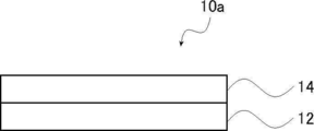
- FIG. 1 shows a cross-sectional view of a first embodiment of the reflective laminate of the present invention.
- the reflective laminate 10 a includes a first reflective layer 12 that reflects right circularly polarized light and a second reflective layer 14 that reflects left circularly polarized light.
- the 1st reflective layer 12 and the 2nd reflective layer 14 have the same degree of helical pitch, and have shown the turning property of the direction opposite to each other. Therefore, the selective reflection wavelength of the first reflective layer 12 and the selective reflection wavelength of the second reflective layer 14 are equal. Therefore, both the right circularly polarized light and the left circularly polarized light having the same wavelength can be reflected by the reflective laminate 10a.
- the first reflective layer 12 and the second reflective layer 14 are layers formed by fixing a dichroic dye in a cholesteric alignment state, and reflect light in a predetermined wavelength band.
- the 1st reflective layer 12 and the 2nd reflective layer 14 originate in the characteristic of a dichroic dye, and absorb the light of visible region. Therefore, for example, when light having a predetermined wavelength in the infrared light region is reflected by the first reflective layer 12 and the second reflective layer 14, when light enters the reflective laminate 10a, the light in the visible light region is absorbed.
- light having a predetermined wavelength in the infrared light region is reflected, and only light in a specific wavelength region can pass through the reflective laminate 10a. That is, the reflective laminate 10a can be used as a selective wavelength transmission filter (band pass filter) having a transmission band in a specific wavelength region.
- the selective reflection wavelength of the first reflective layer 12 indicates a peak at which the reflectance is highest in the reflectance curve (reflectance graph) of the wavelength (horizontal axis) -reflectance (vertical axis) of the first reflective layer 12.
- a wavelength (maximum reflection wavelength) is intended.
- the selective reflection wavelength of the second reflective layer 14 indicates a peak at which the reflectance is highest in the reflectance curve (reflectance graph) of wavelength (horizontal axis) ⁇ reflectance (vertical axis) of the second reflective layer 14.
- a wavelength (maximum reflection wavelength) is intended.
- an absolute reflectance spectrum measurement system V-670, ARMN-735 (manufactured by JASCO Corporation) and the like are used as a method for measuring the selective reflection wavelength.
- the selective reflection wavelength is obtained using the reflectance, but the selective reflection wavelength may be obtained from the transmittance.
- the transmittance can be considered as a value obtained by subtracting the reflectance, the absorption rate, and the scattering rate of the light incident on the sample. In this specification, there is no influence of the absorption of the sample with little scattering.
- the selective reflection wavelength can be evaluated by measuring the transmittance in the wavelength region. That is, the selective reflection wavelength of the reflective layer (the first reflective layer 12 and the second reflective layer 14) is not affected by absorption in the transmittance curve of wavelength (horizontal axis) ⁇ transmittance (vertical axis) of the reflective layer.
- UV-3100PC ultraviolet-visible near-infrared spectrophotometer
- the selective reflection wavelength of the first reflective layer 12 and the selective reflection wavelength of the second reflective layer 14 are equal. “Equal” between the selective reflection wavelengths of the two reflective layers does not mean that they are strictly equal, and an error in a range that does not optically affect is allowed. In this specification, the selective reflection wavelengths of the two reflective layers are “equal” means that the selective reflection wavelength difference between the two reflective layers is 20 nm or less, and the difference is 15 nm or less. Preferably, it is 10 nm or less.
- the transmission spectrum of the reflection laminate shows one strong peak at the selective reflection wavelength, which is preferable from the viewpoint of reflection performance.
- FIG. 1 describes an embodiment in which the selective reflection wavelength of the first reflective layer 12 and the selective reflection wavelength of the second reflective layer 14 are equal, the selective reflection wavelengths of the two may be different.
- the reflective laminate 10a has a transmission band through which light of a predetermined wavelength is transmitted.
- the range of the transmission band is not particularly limited, and can be appropriately adjusted by changing the helical pitch in the first reflective layer and the second reflective layer, the number of stacked layers, and the like.
- the transmission band is preferably in the range of 750 to 1050 nm, and more preferably in the range of 820 to 880 nm or 910 to 970 nm.
- the reflective laminate 10a can absorb light in the visible light region due to the characteristics of the dichroic dye. As light in the visible light region absorbed by the reflective laminate 10a, for example, light in a wavelength band of 400 to 700 nm can be given.
- the total thickness of the first reflective layer 12 and the second reflective layer 14 in the reflective laminate 10a is not particularly limited, but is preferably 10 ⁇ m or less and more preferably 5 ⁇ m or less from the viewpoint of thickness reduction.
- the lower limit is not particularly limited, but is often 1 ⁇ m or more from the viewpoint of handleability.
- the reflective laminate 10a shown in FIG. 1 has one each of the first reflective layer 12 and the second reflective layer 14.
- the present invention is not limited to this mode, and as will be described later, A plurality of reflective layers 12 and second reflective layers 14 may be included. Further, as will be described later, the reflective laminate 10a may include members other than the first reflective layer 12 and the second reflective layer 14.
- first reflective layer and the second reflective layer included in the reflective laminate will be described in detail.
- the first reflective layer is a layer that reflects right circularly polarized light.
- the first reflective layer is a layer formed by fixing a predetermined dichroic dye in a cholesteric alignment state (a layer formed by fixing a cholesteric liquid crystal phase of the dichroic dye).
- the first reflective layer is a layer containing a dichroic dye that is twisted and oriented in the clockwise rotation direction along the helical axis extending in the thickness direction.
- the second reflective layer is a layer that reflects left circularly polarized light.
- the second reflective layer is a layer formed by fixing a predetermined dichroic dye in a cholesteric alignment state (a layer formed by fixing a cholesteric liquid crystal phase of the dichroic dye).
- the second reflective layer is a layer containing a dichroic dye that is twisted and oriented in the left rotation direction along the helical axis extending along the thickness direction.
- the selective reflection wavelengths of the first reflective layer and the second reflective layer are each 600 nm or more.
- the selective reflection wavelength of the first reflective layer and the second reflective layer is preferably in the range of 600 to 2000 nm, and more preferably in the range of 600 to 800 nm or 950 to 1200 nm.
- the definition of the selective reflection wavelength is as described above.
- the thicknesses of the first reflective layer and the second reflective layer are not particularly limited, but are preferably 1 to 5 ⁇ m, more preferably 1 to 3 ⁇ m from the viewpoint of shortening the optical path length.
- Each of the first reflective layer and the second reflective layer is a layer formed by fixing a dichroic dye having an absorption maximum wavelength longer than 400 nm in a cholesteric alignment state.
- the reflection band of the reflection layer is broadened and the reflection efficiency is improved due to the high refractive index anisotropy ⁇ n of the dichroic dye.
- the composition containing the dichroic dye which has a polymeric group was apply
- the composition is preferably subjected to a curing treatment to fix the cholesteric alignment state.
- the first reflective layer and the second reflective layer contain at least a dichroic dye.
- a dichroic dye refers to a dye having the property that the absorbance in the major axis direction of a molecule is different from the absorbance in the minor axis direction.
- the content of the dichroic dye is preferably 45% by mass or more and more preferably 70% by mass or more based on the total mass of the layer. preferable.
- the content of the dichroic dye is within the above range, the reflection band of the reflection layer is further expanded and the reflection efficiency is further improved.
- at least one of the first reflective layer and the second reflective layer is composed of only a dichroic dye and a chiral agent.
- the dichroic dye has an absorption maximum wavelength on the longer wavelength side than 400 nm.
- the maximum absorption wavelength of the dichroic dye is preferably in the range of 450 to 700 nm, more preferably in the range of 500 to 700 nm, from the viewpoint of increasing the refractive index anisotropy ⁇ n of the dichroic dye. preferable.
- the method for measuring the absorption maximum wavelength of the dichroic dye include solution absorption spectrum measurement and film absorption spectrum measurement using an ultraviolet-visible absorption measurement apparatus UV-3100PC (manufactured by Shimadzu Corporation).
- the dichroic dye preferably has liquid crystallinity. More specifically, the dichroic dye preferably has thermotropic liquid crystallinity, that is, exhibits liquid crystallinity by being transferred to the liquid crystal phase by heat. The dichroic dye preferably exhibits nematic liquid crystal properties at 30 to 200 ° C. (preferably 30 to 150 ° C.).
- the refractive index anisotropy ⁇ n of the dichroic dye is not particularly limited, but is preferably 0.5 or more and more preferably 1.0 or more in terms of more excellent effects of the present invention.
- the upper limit is not particularly limited, but is often 2.0 or less.
- a method for measuring the refractive index anisotropy ⁇ n a method using a wedge-shaped liquid crystal cell described in page 202 of a liquid crystal manual (Edited by Liquid Crystal Manual, published by Maruzen Co., Ltd.) is generally used. In the case of a compound that is easily crystallized, it can also be estimated from the extrapolated value by performing evaluation with a mixture with other liquid crystals.
- dichroism in which a horizontal uniaxial alignment state (A plate) is taken on a horizontal alignment cell or alignment film.
- Examples include a method of measuring a liquid crystal film of a dye with AXOSscan manufactured by AXOMETRICS and converting the film thickness.
- the refractive index anisotropy ⁇ n corresponds to a measured value at a wavelength of 800 nm at 35 ° C.
- dichroic dye examples include acridine dyes, oxazine dyes, cyanine dyes, naphthalene dyes, azo dyes, and anthraquinone dyes, and among them, azo dyes are preferable.
- azo dyes examples include a monoazo dye, a bisazo dye, a trisazo dye, a tetrakisazo dye, and a stilbene azo dye.
- a dichroic dye may be used independently and may combine 2 or more types.
- the first reflective layer and the second reflective layer are formed by using a dichroic dye having a polymerizable group (hereinafter also referred to as “polymerizable dichroic dye”).
- a dichroic dye having a polymerizable group hereinafter also referred to as “polymerizable dichroic dye”.
- the kind of the polymerizable group which the dichroic dye has is not particularly limited, and a functional group capable of addition polymerization reaction is preferable, and a polymerizable ethylenically unsaturated group or a ring polymerizable group is preferable.
- the polymerizable group is preferably a (meth) acryloyl group, a vinyl group, a styryl group, an allyl group, an epoxy group, or an oxetane group, and more preferably a (meth) acryloyl group.
- the first reflective layer and the second reflective layer may contain components other than the dichroic dye.
- a liquid crystal compound, an alignment agent, etc. are mentioned, and these components will be described in detail later.
- Step 1 A coating film (composition layer) is formed using a composition containing a dichroic dye, and the coating film is subjected to heat treatment so that the dichroic dye is in a cholesteric alignment state (cholesteric liquid crystal phase).
- Step 2 Step for fixing the cholesteric alignment state
- the composition used in step 1 includes at least a dichroic dye.
- a dichroic dye a polymerizable dichroic dye may be used as described above.
- the composition used in step 1 may contain other components other than the dichroic dye, if necessary.
- the composition may contain a chiral agent.
- a right-turning chiral agent and a left-turning chiral agent can be used.
- the first reflective layer preferably contains a right-turning chiral agent
- the second reflective layer preferably contains a left-turning chiral agent.
- the kind of chiral agent is not particularly limited.
- the chiral agent may be liquid crystalline or non-liquid crystalline.
- the chiral agent includes various known chiral agents (for example, Liquid Crystal Device Handbook, Chapter 3-4-3, TN (twisted nematic), STN (Super Twisted Nematic) chiral agent, page 199, Japan Society for the Promotion of Science, No. 142). From the Committee, 1989).
- Chiral agents generally contain asymmetric carbon atoms.
- an axially asymmetric compound or a planar asymmetric compound that does not contain an asymmetric carbon atom can also be used as a chiral agent.
- Examples of the axial asymmetric compound or the planar asymmetric compound include binaphthyl, helicene, paracyclophane, and derivatives thereof.
- the chiral agent may have a polymerizable group.
- the content of the chiral agent in the composition is not particularly limited, but is preferably 0.5 to 30% by mass with respect to the total solid content of the composition.
- a compound having a strong twisting force is preferable so that a twisted orientation with a desired helical pitch can be achieved even with a small amount.
- Examples of the chiral agent exhibiting such a strong twisting force include, for example, Japanese Patent Application Laid-Open Nos. 2003-287623, 2002-302487, 2002-80478, 2002-80851, and the like. Examples include chiral agents described in Kaikai 2014-034581 and LC-756 manufactured by BASF.
- the composition may contain a liquid crystal compound.
- This liquid crystal compound is a compound different from the dichroic dye.
- the kind in particular of a liquid crystal compound is not restrict
- Liquid crystal compounds can be classified into rod-shaped types (rod-shaped liquid crystal compounds) and disk-shaped types (discotic liquid crystal compounds, disk-shaped liquid crystal compounds) based on their shapes. Furthermore, the rod-shaped type and the disk-shaped type include a low molecular type and a high molecular type, respectively.
- Polymer generally refers to a polymer having a degree of polymerization of 100 or more (Polymer Physics / Phase Transition Dynamics, Masao Doi, 2 pages, Iwanami Shoten, 1992). In the present invention, any liquid crystal compound can be used. Two or more liquid crystal compounds may be used in combination.
- the liquid crystal compound may have a polymerizable group.
- the kind in particular of polymeric group is not restrict
- a preferred embodiment of the liquid crystal compound is a liquid crystal compound having a polymerizable group and having no absorption maximum wavelength on the longer wavelength side than 400 nm.
- this liquid crystal compound By using this liquid crystal compound, an improvement in the stability of the liquid crystal phase by suppressing the crystallization of the liquid crystal compound, an improvement in the curability, and the like can be expected.
- the method for measuring the absorption maximum wavelength of the liquid crystal compound include solution absorption spectrum measurement and film absorption spectrum measurement using an ultraviolet-visible near-infrared spectrophotometer UV-3100PC (manufactured by Shimadzu Corporation).
- the content of the liquid crystal compound in the composition is not particularly limited, but is preferably 1 to 50% by mass and more preferably 5 to 50% by mass with respect to the total solid content of the composition.
- the composition may contain a polymerization initiator.
- the polymerization initiator is preferably a photopolymerization initiator capable of initiating a polymerization reaction by ultraviolet irradiation.
- Examples of the photopolymerization initiator include ⁇ -carbonyl compounds (described in US Pat. Nos. 2,367,661 and 2,367,670), acyloin ether (described in US Pat. No. 2,448,828), ⁇ -hydrocarbon substituted aromatic acyloin. Compound (described in US Pat. No. 2,722,512), polynuclear quinone compound (described in US Pat. Nos.
- the content of the polymerization initiator in the composition is not particularly limited, but is preferably 0.1 to 20% by mass and more preferably 1 to 8% by mass with respect to the total solid content of the composition.
- the composition may contain an alignment control agent.
- an alignment control agent By including an alignment control agent in the composition, it becomes possible to form a stable or rapid cholesteric alignment.
- the orientation control agent include fluorine-containing (meth) acrylate polymers, compounds represented by general formulas (X1) to (X3) described in WO2011 / 162291, and paragraph [0020] of JP2013-47204A. To the compounds described in [0031]. You may contain 2 or more types selected from these. These compounds can reduce the tilt angle of the molecules of the liquid crystal compound (or dichroic dye having liquid crystallinity) or substantially horizontally align it at the air interface of the layer.
- horizontal alignment means that the major axis of the liquid crystal molecule is parallel to the layer surface, but it is not required to be strictly parallel. In this specification, it is defined as a horizontal plane. It shall mean an orientation with an inclination angle of less than 20 °.
- An orientation control agent may be used individually by 1 type, and may use 2 or more types together.
- the content of the alignment control agent in the composition is not particularly limited, but is preferably 0.01 to 10% by mass, more preferably 0.01 to 5% by mass, based on the total solid content of the composition. More preferred is 02 to 1% by mass.
- the composition may contain a solvent.
- an organic solvent is preferable.
- Organic solvents include amides (eg N, N-dimethylformamide); sulfoxides (eg dimethyl sulfoxide); heterocyclic compounds (eg pyridine); hydrocarbons (eg benzene, hexane); alkyl halides (eg chloroform, dichloromethane); esters (Eg, methyl acetate, butyl acetate); ketones (eg, acetone, methyl ethyl ketone); ethers (eg, tetrahydrofuran, 1,2-dimethoxyethane); 1,4-butanediol diacetate and the like.
- amides eg N, N-dimethylformamide
- sulfoxides eg dimethyl sulfoxide
- heterocyclic compounds eg pyridine
- hydrocarbons eg benzene, hexane
- a preferred embodiment of the composition includes a composition containing at least a dichroic dye and a chiral agent.
- the dichroic dye preferably has a polymerizable group.
- the composition containing at least a dichroic dye, a liquid crystal compound, and a chiral agent is mentioned.
- the dichroic dye preferably has a polymerizable group.
- the liquid crystal compound preferably has a polymerizable group.
- the method in particular of forming a coating film using the said composition is not restrict
- coating a composition is mentioned.
- Examples of the coating method include spin coating, dip coating, wire bar coating, direct gravure coating, reverse gravure coating, and die coating.
- the composition can be appropriately applied on a predetermined substrate.
- the substrate may be included in the reflective laminate as will be described later.
- the coating film may be subjected to a drying treatment as necessary. By carrying out the drying treatment, the solvent can be removed from the coating film.
- the coating film is subjected to a heat treatment so that the dichroic dye is cholesterically oriented.
- the dichroic dye itself has liquid crystallinity, for example, by applying a heat treatment to the coating film formed using the composition containing the dichroic dye and the chiral agent, The dye can be cholesterically oriented.
- the method of using together the liquid crystal compound different from a dichroic dye is mentioned, for example.
- the dichroic dye when a coating film formed using a composition containing a dichroic dye, a liquid crystal compound, and a chiral agent is subjected to a heat treatment, the dichroic dye is converted into a cholesteric alignment. In addition, cholesteric orientation can be achieved.
- the method for heating the coating film is not particularly limited.
- the coating film can be stably brought into a cholesteric alignment state by heating it to an isotropic phase temperature and then cooling to a liquid crystal phase transition temperature.
- the phase transition temperature of the composition in the coating film is preferably 10 to 250 ° C., more preferably 10 to 150 ° C. from the viewpoint of production suitability and the like.
- As a preferable heating condition it is preferable to heat the coating film at 50 to 120 ° C. (preferably 50 to 100 ° C.) for 1 to 5 minutes (preferably 1 to 3 minutes).
- Step 2 is a step of fixing the cholesteric alignment state formed in the coating film.
- the fixing method is not particularly limited, but when the dichroic dye and / or the liquid crystal compound used in combination with the dichroic dye has a polymerizable group, the coating treatment in the cholesteric alignment state is cured. By performing (for example, light irradiation treatment or heat treatment), the orientation state can be fixed. Further, the method for fixing the cholesteric alignment state may be a method other than the above (for example, rapid cooling treatment).
- the method for the curing treatment is not particularly limited, and examples thereof include photocuring treatment and thermosetting treatment. Of these, light irradiation treatment is preferable, and ultraviolet irradiation treatment is more preferable.
- a light source such as an ultraviolet lamp is used.
- the amount of ultraviolet irradiation energy is not particularly limited, but is generally preferably about 0.1 to 1.0 J / cm 2 .
- the time for irradiation with ultraviolet rays is not particularly limited, and may be appropriately determined from the viewpoints of both the strength and productivity of the resulting reflective layer. In order to accelerate the curing reaction, ultraviolet irradiation may be performed under heating conditions.
- the cholesteric orientation (cholesteric liquid crystal phase) of the dichroic dye is fixed, and a reflective layer is formed.
- the state in which the cholesteric orientation (cholesteric liquid crystal phase) is “fixed” is the most typical and preferred state in which the orientation of the dichroic dye is maintained.
- the layer has no fluidity in the temperature range of usually 0 to 50 ° C., and -30 to 70 ° C. under severer conditions, and the orientation form is changed by an external field or external force. In other words, it means a state in which the fixed orientation form can be kept stable.
- the reflective layer it is sufficient that the optical properties of the cholesteric alignment (cholesteric liquid crystal phase) are maintained in the layer, and the composition in the reflective layer does not need to exhibit liquid crystal properties.
- the 1st reflective layer and the 2nd reflective layer in a reflective layered product can each be manufactured by the method mentioned above.
- the manufacturing order in particular with a 1st reflective layer and a 2nd reflective layer is not restrict
- a composition containing a dichroic dye having a polymerizable group, a right-turning chiral agent, and a polymerization initiator into a cholesteric alignment state
- the composition containing the step X of forming the first reflective layer, the dichroic dye having a polymerizable group, the left-rotating chiral agent, and the polymerization initiator was brought into a cholesteric alignment state by immobilization.
- the manufacturing method of the reflective laminated body which has the process Y which forms a 2nd reflective layer by fixing later is preferable. Either step X or step Y may be performed first.
- the content of the dichroic dye having a polymerizable group in the composition used in Step X and Step Y is not particularly limited, but the total effect of the present invention is superior to the total solid content in the composition. 45 mass% or more is preferable, and 70 mass% or more is more preferable.
- the solid content in the composition is preferably composed only of a dichroic dye, a chiral agent, a polymerization initiator, and an alignment controller.
- the reflective laminate may include a substrate that supports the first reflective layer and the second reflective layer. That is, the reflective laminated body which has a board
- the substrate a known substrate can be used, and examples thereof include a resin substrate and a glass substrate.
- the reflective laminate may include an alignment film.
- the alignment film can be used in manufacturing the first reflective layer and / or the second reflective layer.
- a known alignment film can be used as the alignment film.
- the coating film is dried by heating (crosslinking), and further, the coating film is subjected to a rubbing treatment.
- a treatment method widely adopted as a liquid crystal alignment treatment process of LCD (liquid crystal display) can be applied.
- the reflective laminate may include an ultraviolet absorbing layer.
- the ultraviolet absorbing layer preferably contains an ultraviolet absorber.
- the kind in particular of ultraviolet absorber is not restrict
- the ultraviolet absorption layer may contain a binder as necessary.
- the ultraviolet absorbing layer preferably has absorption in the visible light region in that it provides the reflective laminate with absorption characteristics in a wider range of wavelengths. More specifically, it preferably has absorption in the wavelength region of 200 to 500 nm.
- the thickness of the ultraviolet absorbing layer is not particularly limited, but is preferably 0.1 to 5 ⁇ m, more preferably 1 to 3 ⁇ m.
- the ultraviolet absorbing layer may be formed as a layer separate from the above-described member (for example, a substrate). Further, an ultraviolet absorbent may be contained in the substrate, and a substrate having an ultraviolet absorbing ability may be used as the ultraviolet absorbing layer.
- the reflective laminate may include a light absorption layer that absorbs at least one of visible light and near infrared light (hereinafter, also simply referred to as “light absorption layer”).
- the light absorption layer is disposed in the reflection layered body, so that the reflection layered body Can be used as a band-pass filter that transmits only the necessary wavelength.
- the light absorption layer is a layer that absorbs at least one (one or both) of visible light and near infrared light. Examples of visible light include light having a wavelength band of 400 to 700 nm. Moreover, as near-infrared light, light in a wavelength band of more than 700 nm and not more than 2000 nm can be mentioned.
- the kind in particular of the light absorption material contained in a light absorption layer is not restrict
- the light absorption layer may contain a binder.
- the kind in particular of a binder is not restrict
- the binder include (meth) acrylic resin, styrene resin, urethane resin, epoxy resin, polyolefin resin, and polycarbonate resin.
- the binder contained in the light absorption layer may be synthesized by including a polymerizable compound in the composition for forming the light absorption layer used for forming the light absorption layer and polymerizing the polymerizable compound. Good. Further, as the binder, a pigment dispersant and an alkali-soluble resin may be contained.
- the light absorbing layer may contain at least one of an ultraviolet light absorbing material and a near infrared light absorbing material.
- the light absorption layer preferably contains both the ultraviolet light absorption material and the near infrared light absorption material.
- Known materials can be used as the ultraviolet light absorbing material.
- Near infrared light absorbing materials include diketopyrrolopyrrole dye compounds, copper compounds, cyanine dye compounds, phthalocyanine compounds, imonium compounds, thiol complex compounds, transition metal oxide compounds, squarylium dye compounds, Examples include phthalocyanine dye compounds, quatarylene dye compounds, dithiol metal complex dye compounds, and croconium compounds.
- the maximum absorption wavelength of the near infrared light absorbing material is preferably in the range of 600 to 1000 nm.
- the maximum absorption wavelength of the near-infrared light absorbing material is located on the shorter wavelength side than 850 nm or the shorter wavelength side than 940 nm, which is used as a near-infrared LED (Light Emitting Diode) light source wavelength. Is more preferable.
- the thickness of the light absorption layer is not particularly limited, but is preferably 0.1 to 3 ⁇ m, and more preferably 0.5 to 1 ⁇ m.
- the light absorption layer may be formed as a layer separate from the above-described member (for example, a substrate). Further, a substrate that absorbs at least one of visible light and near infrared light by containing at least one of a visible light absorber and a near infrared light absorbing material in the substrate may be used as the light absorbing layer.
- the reflective laminate can be applied to various uses.
- a band pass filter can be used.
- the band-pass filter refers to a filter set so as to pass only light in a specific wavelength band.
- the band-pass filter including the reflective laminate is included in, for example, a selective wavelength sensor.
- the selected wavelength sensor may include a light receiving unit.
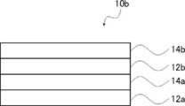
- FIG. 2 shows a cross-sectional view of a second embodiment of the reflective laminate of the present invention.
- FIG. 2 is a cross-sectional view showing an example of a reflective laminate in the case where two or more first reflective layers 12 and second reflective layers 14 are provided.
- the reflective laminate 10b shown in FIG. 2 includes a first reflective layer 12a, a second reflective layer 14a, a first reflective layer 12b, and a second reflective layer 14b.
- the reflective laminate 10a shown in FIG. 2 and the reflective laminate 10b shown in FIG. 1 have the same configuration except that the number of layers of the first reflective layer and the second reflective layer is different.
- the first reflective layer 12a and the first reflective layer 12b are layers that reflect right circularly polarized light, and the selective reflection wavelengths thereof are different. More specifically, the selective reflection wavelength of the first reflective layer 12a is located on the longer wavelength side than the selective reflection wavelength of the first reflective layer 12b.
- the second reflective layer 14a and the second reflective layer 14b are both layers that reflect left circularly polarized light, and have different selective reflection wavelengths. More specifically, the selective reflection wavelength of the second reflective layer 14a is located on the longer wavelength side than the selective reflection wavelength of the second reflective layer 14b.
- the 1st reflective layer 12a and the 2nd reflective layer 14a have the substantially same helical pitch, and both selective reflection wavelengths are equal.
- the first reflective layer 12b and the second reflective layer 14b have substantially the same spiral pitch, and the selective reflection wavelengths of both are the same.
- the first reflective layer 12a and the second reflective layer 14a play a role of reflecting light on the longer wavelength side
- the first reflective layer 12b and the second reflective layer 14b are on the shorter wavelength side. It plays the role of reflecting the light of That is, by using four reflective layers, light in a wide wavelength range is reflected complementarily.
- the total number of first reflective layers and the total number of second reflective layers are independent of each other, and may be the same or different, but are preferably the same.
- the reflective laminate may have two or more sets each composed of one first reflective layer and one second reflective layer. At this time, it is more preferable that the selective reflection wavelength of the first reflective layer and the selective reflection wavelength of the second reflective layer included in each set are equal to each other.
- the selective reflection wavelengths of the first reflection layers are different from each other. This is because even if there are a plurality of first reflective layers having the same selective reflection wavelength, the reflection efficiency does not increase.
- that the selective reflection wavelengths of the two first reflective layers are different from each other means that the difference between the two selective reflection wavelengths exceeds at least 20 nm.
- the selective reflection wavelength difference between the first reflective layers is preferably more than 20 nm, more preferably 30 nm or more, and even more preferably 40 nm or more. .
- the selective reflection wavelengths of the second reflective layers are different from each other.
- the difference in selective reflection wavelength between the second reflective layers is preferably more than 20 nm, more preferably 30 nm or more, and even more preferably 40 nm or more.
- the reflective laminate has two or more sets each composed of one first reflective layer and one second reflective layer
- the selective reflection wavelengths of the first reflective layers included in different sets are different from each other. It is preferable that the selective reflection wavelengths of the second reflective layers included in different sets are different from each other.
- the polymerizable dichroic dye A has liquid crystallinity and is a nematic liquid crystal having an isotropic phase transition temperature of 118 ° C. Moreover, it was confirmed that it was a dichroic dye by observation with a polarizing microscope.
- the absorption maximum wavelength of the polymerizable dichroic dye A was 542 nm.
- ⁇ n at a wavelength of 800 nm at a temperature of 35 ° C. was 1.18.
- the maximum absorption wavelength of the polymerizable liquid crystal 1 was 266 nm.
- ⁇ Formation of reflective layer> The surface of the alignment film in the glass substrate with the alignment film (SE-130 manufactured by Nissan Chemical Industries, Ltd.) was rubbed. Next, using the coating solution (R1) prepared above, a reflective layer having a selective reflection wavelength of about 1000 nm was produced on the alignment film surface by the following procedure. (1) A coating solution (R1) at room temperature on the alignment film in the glass substrate with an alignment film (SE-130 manufactured by Nissan Chemical Industries, Ltd.) so that the thickness of the dried film is 2.5 ⁇ m. was applied with a spin coater. (2) After the coating film was dried at room temperature for 30 seconds to remove the solvent, the coating film was heated in an atmosphere of 100 ° C.
- cholesteric-align the dichroic dye for 1 minute to cholesteric-align the dichroic dye to form a cholesteric liquid crystal phase.
- UV (ultraviolet light) irradiation 28.6 mW / cm 2 , 35 seconds
- a cholesteric liquid crystal phase was fixed, and a reflective layer (FR1) formed by fixing a dichroic dye on a glass substrate in a cholesteric alignment state was produced.
- the reflective layers (FR2) and (FL1) were produced in the same manner as the reflective layer (FR1) except that the coating liquids (R2) and (L1) were used instead of the coating liquid (R1). did.
- ⁇ Preparation of reflective laminate> (1) The coating liquid (L1) was applied on the reflective layer (FR1) at room temperature with a spin coater so that the thickness of the dried film was 2.5 ⁇ m. (2) After the coating film was dried at room temperature for 30 seconds to remove the solvent, the coating film was heated in an atmosphere of 100 ° C. for 1 minute to cholesteric-align the dichroic dye to form a cholesteric liquid crystal phase. Next, UV irradiation (28.6 mW / cm 2 , 35 seconds) was performed on the coating film at 80 ° C. under a nitrogen atmosphere using HOYA-SCHOTT EXECUTE-3000W manufactured by HOYA CANDEO OPTRONICS Co., Ltd. A cholesteric liquid crystal phase was fixed to produce a reflective laminate (F1).
- ⁇ Preparation of coating solution (CR1)> Polymerizable liquid crystal 1, fluorine-based horizontal alignment agent 1, chiral agent, polymerization initiator, and solvent were mixed to prepare a coating liquid (CR1) having the following composition.
- Polymerizable liquid crystal 1 100 parts by mass Fluorine-based horizontal alignment agent 1 0.1 part by mass Right-turning chiral agent LC756 (manufactured by BASF) 1.65 parts by mass Polymerization initiator IRGACURE819 (manufactured by Ciba Japan) 4 Part by mass / Solvent (Chloroform) Amount of solute concentration of 15% by mass
- ⁇ Preparation of coating solution (CL1)> A polymerizable liquid crystal 1, a fluorine-based horizontal alignment agent 1, a chiral agent, a polymerization initiator, and a solvent were mixed to prepare a coating liquid (CL1) having the following composition.
- -Polymerizable liquid crystal 1 100 parts by mass-Fluorine-based horizontal alignment agent 1 0.1 part by mass-Left-turning chiral agent 1 5.5 parts by mass-Polymerization initiator IRGACURE 819 (manufactured by Ciba Japan) 4 parts by mass-Solvent (chloroform) )
- Reflective layers (CFR1) and (CFL1) were prepared in the same manner as the reflective layer (FR1) except that the coating liquids (CR1) and (CL1) were used instead of the coating liquid (R1).
- the transmission spectra of the reflective layers (FR1), (FR2), (FL1), (CFR1), (CFL1) and the reflective laminate (F1) are converted into an ultraviolet-visible near-infrared spectrophotometer UV-3100PC (manufactured by Shimadzu Corporation). The results measured at are shown in FIGS. Note that the measurement was performed by performing a baseline process on a glass substrate with an alignment film.
- the selective reflection wavelength of the reflective layer (FR1) is 1040 nm
- the selective reflection wavelength of the reflective layer (FR2) is 990 nm
- the selective reflection wavelength of the reflective layer (FL1) is 1000 nm
- the selective reflection of the reflective layer (CFR1) The wavelength was 1020 nm
- the selective reflection wavelength of the reflective layer (CFL1) was 1000 nm.
- the reflective layers (FR1), (FR2), and (FL1) correspond to the reflective layers (CFR1) and (CFL1) corresponding to the comparative example not using the dichroic dye. Can efficiently reflect light in a wide wavelength band. A reflective laminate including such a reflective layer can also efficiently reflect light in a wide wavelength band.
- the reflective layers (FR1), (FR2), and (FL1) have a light-shielding property due to dye absorption in a wavelength band of 700 nm or less.
- the reflection layer (FR1) having the reflection characteristic for the right circularly polarized light and the (FL1) having the reflection characteristic for the left circularly polarized light have a wide reflection band in the near infrared light region. It turns out that a reflective laminated body (F1) is obtained.
Landscapes
- Physics & Mathematics (AREA)
- General Physics & Mathematics (AREA)
- Optics & Photonics (AREA)
- Health & Medical Sciences (AREA)
- Toxicology (AREA)
- Chemical & Material Sciences (AREA)
- Crystallography & Structural Chemistry (AREA)
- Polarising Elements (AREA)
- Optical Filters (AREA)
- Laminated Bodies (AREA)
Abstract
Description
例えば、特許文献1においては、バンドパスフィルターとして、コレステリック液晶相の選択反射特性を利用した反射層を用いることが提案されている。
一般的に、コレステリック液晶相の選択反射特性を利用した反射層を用いる場合、選択反射波長が異なる複数の反射層を積層することにより、幅広い波長帯域の光を反射している。しかし、幅広い波長帯域の光を効率よく反射することができる反射層であれば、反射層の積層数を減らすことができ、薄型化にもつながる。
本発明者は、特許文献1に記載されるような、公知のコレステリック液晶相の選択反射特性を利用した反射層の特性について検討を行ったところ、反射波長帯域が必ずしも広くなく、かつ、その反射特性も十分ではなく、更なる改良が必要であることを知見している。
また、本発明は、上記反射積層体の製造方法、バンドパスフィルター、および、選択波長センサーを提供することも課題とする。
すなわち、本発明者は、以下の構成により上記課題が解決できることを見出した。
第1反射層および第2反射層の選択反射波長がそれぞれ600nm以上であり、
第1反射層および第2反射層が、それぞれ、400nmよりも長波長側に吸収極大波長を有する二色性色素をコレステリック配向状態において固定化してなる層である、反射積層体。
(2) 第1反射層および第2反射層の少なくとも1つにおいて、二色性色素の含有量が、層全質量に対して、45質量%以上である、(1)に記載の反射積層体。
(3) 二色性色素が液晶性を有する、(1)または(2)に記載の反射積層体。
(4) 第1反射層の膜厚および第2反射層の膜厚の合計値が10μm以下である、(1)~(3)のいずれかに記載の反射積層体。
(5) さらに、紫外線吸収層を有する、(1)~(4)のいずれかに記載の反射積層体。
(6) 紫外線吸収層が、可視光領域に吸収を有する、(5)に記載の反射積層体。
(7) さらに、可視光および近赤外光の少なくとも一方を吸収する光吸収層を有する、(1)~(6)のいずれかに記載の反射積層体。
(8) (1)~(7)のいずれかに記載の反射積層体を含む、バンドパスフィルター。
(9) (8)に記載のバンドパスフィルターを含む、選択波長センサー。
(10) (1)~(7)のいずれかに記載の反射積層体の製造方法であって、
重合性基を有する二色性色素、右旋回性のキラル剤、および、重合開始剤を含む組成物をコレステリック配向状態にした後に、固定化することによって、第1反射層を形成する工程と、
重合性基を有する二色性色素、左旋回性のキラル剤、および、重合開始剤を含む組成物をコレステリック配向状態にした後に、固定化することによって、第2反射層を形成する工程と、を有する反射積層体の製造方法。
(11) 重合性基を有する二色性色素の含有量が、組成物中の全固形分に対して、45質量%以上である、(10)に記載の反射積層体の製造方法。
(12) 組成物が、重合性基を有する液晶化合物であって、400nmよりも長波長側に吸収極大波長を有さない液晶化合物を含む、(10)または(11)に記載の反射積層体の製造方法。
また、本発明によれば、上記反射積層体の製造方法、バンドパスフィルター、および、選択波長センサーを提供できる。
以下に記載する構成要件の説明は、本発明の代表的な実施態様に基づいてなされるが、本発明はそのような実施態様に制限されるものではない。
なお、本明細書において「~」を用いて表される数値範囲は、「~」の前後に記載される数値を下限値および上限値として含む範囲を意味する。
図1は、本発明の反射積層体の第1実施態様の断面図を示す。
図1に示すように、反射積層体10aは、右円偏光を反射する第1反射層12と、左円偏光を反射する第2反射層14とを備える。
第1反射層12および第2反射層14は、同程度の螺旋ピッチを有するとともに、互いに逆向きの旋回性を示している。そのため、第1反射層12の選択反射波長と第2反射層14の選択反射波長とは等しい。従って、反射積層体10aによって、同程度の波長の右円偏光および左円偏光のいずれも反射できる。
また、後段で詳述するように、第1反射層12および第2反射層14は、二色性色素をコレステリック配向状態において固定化してなる層であり、所定の波長帯域の光を反射する。また、第1反射層12および第2反射層14は、二色性色素の特性に由来して可視光領域の光を吸収する。そのため、例えば、第1反射層12および第2反射層14によって赤外光領域の所定の波長の光が反射される場合、反射積層体10aに光が入射すると、可視光領域の光は吸収され、かつ、赤外光領域の所定の波長の光は反射され、特定の波長領域の光のみが反射積層体10aを透過できる。つまり、反射積層体10aは、特定の波長領域に透過帯域を有する、選択波長透過フィルター(バンドパスフィルター)として利用可能である。
第2反射層14の選択反射波長とは、第2反射層14の波長(横軸)-反射率(縦軸)の反射率曲線(反射率グラフ)において、反射率が最も高くなるピークを示す波長(極大反射波長)を意図する。
選択反射波長の測定方法としては、絶対反射率スペクトル測定システムV-670およびARMN-735(日本分光株式会社製)などが用いられる。
なお、上記では、反射率を用いて選択反射波長を求めているが、透過率より選択反射波長を求めてよい。透過率とは、試料に入射した光のうち、反射率、吸収率および散乱率を差し引いた値であると考えることができ、本明細書中においては、散乱が少ない試料の吸収の影響がない波長領域における透過率を測定することで、選択反射波長を評価できる。つまり、反射層(第1反射層12、第2反射層14)の選択反射波長とは、反射層の波長(横軸)-透過率(縦軸)の透過率曲線において、吸収の影響がない波長領域における透過率が最も低くなるピークを示す波長(極大反射波長)として求めることもできる。
透過率の測定方法としては、紫外可視近赤外分光光度計UV-3100PC(株式会社島津製作所製)などが用いられる。
選択反射波長が互いに等しく、左右異なる旋回性を有する2つの反射層を積層することで、反射積層体の透過スペクトルは、この選択反射波長において1つの強いピークを示し、反射性能の観点から好ましい。
なお、図1では、第1反射層12の選択反射波長と第2反射層14の選択反射波長とが等しい態様について述べるが、両者の選択反射波長は異なっていてもよい。
透過帯域の範囲は特に制限されず、第1反射層および第2反射層中の螺旋ピッチ、および、積層数などを変えることにより、適宜調整可能である。透過帯域は、750~1050nmの範囲内にあることが好ましく、820~880nmまたは910~970nmの範囲内にあることがより好ましい。
上述したように、反射積層体10aは、二色性色素の特性に由来して、可視光領域の光を吸収できる。反射積層体10aによって吸収される可視光領域の光としては、例えば、400~700nmの波長帯域の光が挙げられる。
また、後述するように、反射積層体10aには、第1反射層12および第2反射層14以外の部材が含まれていてもよい。
第1反射層は、右円偏光を反射する層である。第1反射層は、後述するように、所定の二色性色素をコレステリック配向状態において固定化してなる層(二色性色素のコレステリック液晶相を固定化してなる層)である。言い換えれば、第1反射層は、厚み方向に沿って延びる螺旋軸に沿って右回転方向にて捩れ配向した二色性色素を含む層である。
第2反射層は、左円偏光を反射する層である。第2反射層は、後述するように、所定の二色性色素をコレステリック配向状態において固定化してなる層(二色性色素のコレステリック液晶相を固定化してなる層)である。言い換えれば、第2反射層は、厚み方向に沿って延びる螺旋軸に沿って左回転方向にて捩れ配向した二色性色素を含む層である。
なお、選択反射波長の定義は、上述の通りである。
なお、第1反射層および第2反射層の好適態様としては、後述するように、重合性基を有する二色性色素を含む組成物を塗布し、塗布された組成物中の二色性色素をコレステリック配向させた後、組成物に対して硬化処理を施し、コレステリック配向状態を固定化してなる層であることが好ましい。
第1反射層および第2反射層には、少なくとも二色性色素が含まれる。
二色性色素とは、分子の長軸方向における吸光度と、短軸方向における吸光度とが異なる性質を有する色素をいう。
なお、第1反射層および第2反射層の少なくも1つにおいて、二色性色素およびキラル剤のみから構成されることが好ましい。
二色性色素の吸収極大波長の測定方法としては、紫外可視吸収測定装置UV-3100PC(株式会社島津製作所製)を用いた溶液吸収スペクトル測定および膜吸収スペクトル測定などが挙げられる。
屈折率異方性Δnの測定方法としては、液晶便覧(液晶便覧編集委員会編、丸善株式会社刊)202頁に記載の楔形液晶セルを用いた方法が一般的である。なお、結晶化しやすい化合物の場合は、他の液晶との混合物による評価を行い、その外挿値から見積もることもできる。近赤外光領域(例えば、波長700nm超800nmの波長領域)におけるΔnを簡易的に見積もる方法としては、水平配向セルまたは配向膜上で水平一軸配向状態(Aプレート)を取らせた二色性色素の液晶膜をAXOMETRICS社製AXOScanで測定し、膜厚で換算する方法なども挙げられる。
なお、上記屈折率異方性Δnは、35℃における波長800nmでの測定値に該当する。
二色性色素は、単独で使用してもよく、2種以上を組み合わせてもよい。
二色性色素が有する重合性基の種類は特に制限されず、付加重合反応が可能な官能基が好ましく、重合性エチレン性不飽和基または環重合性基が好ましい。より具体的には、重合性基としては、(メタ)アクリロイル基、ビニル基、スチリル基、アリル基、エポキシ基、または、オキセタン基が好ましく、(メタ)アクリロイル基がより好ましい。
第1反射層および第2反射層の製造方法は特に制限されず、公知の方法を採用できる。なかでも、反射層の特性(例えば、選択反射波長)を制御しやすい点で、以下の工程1および工程2を有する製造方法が好ましい。
工程1:二色性色素を含む組成物を用いて塗膜(組成物層)を形成し、塗膜に対して加熱処理を施して、二色性色素をコレステリック配向状態(コレステリック液晶相)とする工程
工程2:コレステリック配向状態を固定化する工程
以下、各工程について詳述する。
工程1で使用される組成物には、少なくとも二色性色素が含まれる。二色性色素としては、上述したように重合性二色性色素を用いてもよい。
工程1で使用される組成物には、必要に応じて、二色性色素以外の他の成分が含まれていてもよい。
組成物には、キラル剤が含まれていてもよい。
キラル剤としては、右旋回性のキラル剤および左旋回性のキラル剤を用いることができる。具体的には、第1反射層には右旋回性のキラル剤が含まれることが好ましく、第2反射層には左旋回性のキラル剤が含まれることが好ましい。
キラル剤の種類は、特に制限されない。キラル剤は液晶性であっても、非液晶性であってもよい。キラル剤は、公知の種々のキラル剤(例えば、液晶デバイスハンドブック、第3章4-3項、TN(twisted nematic)、STN(Super Twisted Nematic)用カイラル剤、199頁、日本学術振興会第142委員会編、1989に記載)から選択することができる。キラル剤は、一般に不斉炭素原子を含む。ただし、不斉炭素原子を含まない軸性不斉化合物または面性不斉化合物を、キラル剤として用いることもできる。軸性不斉化合物または面性不斉化合物の例には、ビナフチル、ヘリセン、パラシクロファンおよびこれらの誘導体が含まれる。キラル剤は、重合性基を有していてもよい。
このような強い捩り力を示すキラル剤としては、例えば、特開2003-287623号公報、特開2002-302487号公報、特開2002-80478号公報、特開2002-80851号公報、および、特開2014-034581号公報に記載のキラル剤、ならびに、BASF社製のLC-756などが挙げられる。
組成物は、液晶化合物を含んでいてもよい。この液晶化合物は、二色性色素とは異なる化合物である。
液晶化合物の種類は特に制限されず、公知の液晶化合物を用いることができる。液晶化合物はその形状から、棒状タイプ(棒状液晶化合物)と円盤状タイプ(ディスコティック液晶化合物、円盤状液晶化合物)とに分類できる。さらに、棒状タイプおよび円盤状タイプには、それぞれ低分子タイプと高分子タイプとがある。高分子とは一般に重合度が100以上のものを指す(高分子物理・相転移ダイナミクス,土井 正男 著,2頁,岩波書店,1992)。本発明では、いずれの液晶化合物を用いることもできる。また、2種以上の液晶化合物を併用してもよい。
液晶化合物の吸収極大波長の測定方法としては、紫外可視近赤外分光光度計UV-3100PC(株式会社島津製作所製)を用いた溶液吸収スペクトル測定および膜吸収スペクトル測定などが挙げられる。
組成物は、重合開始剤を含んでいてもよい。
重合開始剤としては、紫外線照射によって重合反応を開始可能な光重合開始剤であることが好ましい。光重合開始剤としては、α-カルボニル化合物(米国特許第2367661号、同2367670号の各明細書記載)、アシロインエーテル(米国特許第2448828号明細書記載)、α-炭化水素置換芳香族アシロイン化合物(米国特許第2722512号明細書記載)、多核キノン化合物(米国特許第3046127号、同2951758号の各明細書記載)、トリアリールイミダゾールダイマーとp-アミノフェニルケトンとの組み合わせ(米国特許第3549367号明細書記載)、アクリジンおよびフェナジン化合物(特開昭60-105667号公報、米国特許第4239850号明細書記載)、ならびに、オキサジアゾール化合物(米国特許第4212970号明細書記載)などが挙げられる。
組成物中での重合開始剤の含有量は特に制限されないが、組成物の全固形分に対して、0.1~20質量%が好ましく、1~8質量%がより好ましい。
組成物は、配向制御剤を含んでいてもよい。配向制御剤が組成物に含まれることにより、安定的または迅速なコレステリック配向の形成が可能となる。
配向制御剤としては、例えば、含フッ素(メタ)アクリレート系ポリマー、WO2011/162291に記載の一般式(X1)~(X3)で表される化合物、および、特開2013-47204の段落[0020]~[0031]に記載の化合物が挙げられる。これらから選択される2種以上を含有していてもよい。これらの化合物は、層の空気界面において、液晶化合物(または、液晶性を有する二色性色素)の分子のチルト角を低減または実質的に水平配向させることができる。なお、本明細書で「水平配向」とは、液晶分子長軸と層面が平行であることをいうが、厳密に平行であることを要求するものではなく、本明細書では、水平面とのなす傾斜角が20°未満の配向を意味するものとする。
配向制御剤は、1種単独で用いてもよいし、2種以上を併用してもよい。
組成物中での配向制御剤の含有量は特に制限されないが、組成物の全固形分に対して、0.01~10質量%が好ましく、0.01~5質量%がより好ましく、0.02~1質量%がさらに好ましい。
組成物は、溶剤を含んでいてもよい。
溶剤としては、有機溶剤が好ましい。有機溶剤としては、アミド(例えばN,N-ジメチルホルムアミド);スルホキシド(例えばジメチルスルホキシド);ヘテロ環化合物(例えばピリジン);炭化水素(例えばベンゼン、ヘキサン);アルキルハライド(例えばクロロホルム、ジクロロメタン);エステル(例えば酢酸メチル、酢酸ブチル);ケトン(例えばアセトン、メチルエチルケトン);エーテル(例えばテトラヒドロフラン、1,2-ジメトキシエタン);1,4-ブタンジオールジアセテートなどが挙げられる。
また、二色性色素が液晶性を有さない場合、組成物の好適態様としては、二色性色素と、液晶化合物と、キラル剤とを少なくとも含む組成物が挙げられる。なお、この場合、二色性色素が重合性基を有することが好ましい。また、液晶化合物が重合性基を有することが好ましい。
上記組成物を用いて塗膜を形成する方法は特に制限されず、組成物を塗布する方法が挙げられる。
塗布方法としては、スピンコート法、ディップコート法、ワイヤーバーコーティング法、ダイレクトグラビアコーティング法、リバースグラビアコーティング法、および、ダイコーティング法などが挙げられる。
なお、組成物は、所定の基板上に適宜塗布できる。基板は、後述するように、反射積層体に含まれていてもよい。
上記塗膜を形成した後、必要に応じて、塗膜に対して乾燥処理を施してもよい。乾燥処理を実施することにより、塗膜から溶媒を除去できる。
なお、二色性色素自体が液晶性を有する場合は、例えば、二色性色素とキラル剤とを含む組成物を用いて形成された塗膜に対して加熱処理を施すことにより、二色性色素をコレステリック配向させることができる。
また、二色性色素が液晶性を有さない場合は、例えば、二色性色素とは異なる液晶化合物を併用する方法が挙げられる。つまり、二色性色素、液晶化合物、および、キラル剤を含む組成物を用いて形成された塗膜に対して加熱処理を施すことにより、液晶化合物がコレステリック配向する際に、二色性色素を合わせてコレステリック配向させることができる。
塗膜中の組成物の相転移温度は、製造適性などの面から、10~250℃が好ましく、10~150℃がより好ましい。
好ましい加熱条件としては、50~120℃(好ましくは、50~100℃)で1~5分間(好ましくは、1~3分間)にわたって塗膜を加熱することが好ましい。
工程2は、塗膜中に形成されたコレステリック配向状態を固定化する工程である。
固定化の方法は特に制限されないが、二色性色素、および/または、二色性色素と併用される液晶化合物が重合性基を有する場合は、コレステリック配向状態の塗膜に対して、硬化処理(例えば、光照射処理または加熱処理)を施すことにより、その配向状態を固定化できる。
また、コレステリック配向状態の固定化の方法は、上記以外の方法(例えば、急冷処理)であってもよい。
紫外線照射には、紫外線ランプなどの光源が利用される。
紫外線の照射エネルギー量は特に制限されないが、一般的には、0.1~1.0J/cm2程度が好ましい。また、紫外線を照射する時間は特に制限されず、得られる反射層の強度および生産性の双方の観点から適宜決定すればよい。
硬化反応を促進するため、加熱条件下で紫外線照射を実施してもよい。
なお、反射層においては、コレステリック配向(コレステリック液晶相)の光学的性質が層中において保持されていれば十分であり、最終的に反射層中の組成物がもはや液晶性を示す必要はない。
なお、第1反射層と第2反射層との製造順番は特に制限されず、どちらを先に(順不同で)製造してもよい。つまり、第1反射層を製造して第1反射層上に第2反射層を製造してもよいし、第2反射層を製造して第2反射層上に第1反射層を製造してもよい。
工程Xおよび工程Yは、どちらを先に実施してもよい。
工程Xおよび工程Yで用いられる組成物中における重合性基を有する二色性色素の含有量は特に制限されないが、本発明の効果がより優れる点で、組成物中の全固形分に対して、45質量%以上が好ましく、70質量%以上がより好ましい。
なお、組成物中の固形分は、二色性色素、キラル剤、重合開始剤、および、配向制御剤のみで構成されていることが好ましい。
反射積層体には、上述した第1反射層および第2反射層以外の部材が含まれていてもよい。以下、任意の部材について詳述する。
例えば、反射積層体には、第1反射層および第2反射層を支持する基板が含まれていてもよい。つまり、基板と、第1反射層と、第2反射層とを有する反射積層体であってもよい。
基板としては、公知の基板を用いることができ、樹脂基板、および、ガラス基板などが挙げられる。
また、反射積層体には、配向膜が含まれていてもよい。配向膜は、第1反射層および/または第2反射層の製造の際に用いることができる。
配向膜としては、公知の配向膜を用いることができる。例えば、配向膜形成材料(例えば、ポリマー)を含む溶液を基板上に塗布した後、塗膜を加熱乾燥(架橋させ)し、さらに塗膜にラビング処理を施すことにより形成できる。
ラビング処理は、LCD(liquid crystal display)の液晶配向処理工程として広く採用されている処理方法を適用できる。
また、反射積層体には、紫外線吸収層が含まれていてもよい。光が入射する側の反射積層体の最外面側に紫外線吸収層を配置することにより、第1反射層および第2反射層の光劣化を抑制することができる。
紫外線吸収層には、紫外線吸収剤が含まれることが好ましい。紫外線吸収剤の種類は特に制限されず、公知の紫外線吸収剤を用いることができる。例えば、サリチル酸系紫外線吸収剤、ベンゾフェノン系紫外線吸収剤、ベンゾトリアゾール系紫外線吸収剤、シアノアクリレート系紫外線吸収剤、ベンゾエート系紫外線吸収剤、マロン酸エステル系紫外線吸収剤、および、シュウ酸アニリド系紫外線吸収剤などが挙げられる。
なお、紫外線吸収層には、必要に応じて、バインダーが含まれていてもよい。
紫外線吸収層の厚みは特に制限されないが、0.1~5μmが好ましく、1~3μmがより好ましい。
紫外線吸収層は、上述した部材(例えば、基板)とは別個の層として形成してもよい。また、上記基板に紫外線吸収剤を含有させて、紫外線吸収能のある基板を紫外線吸収層として用いてもよい。
また、反射積層体には可視光および近赤外光の少なくとも一方を吸収する光吸収層(以後、単に「光吸収層」とも称する)が含まれていてもよい。上記二色性色素で形成された反射波長領域および吸収波長領域を除く透過光領域における不要な波長領域を吸収するために、上記光吸収層を反射積層体中に配置することで、反射積層体を必要な波長のみを透過させるバンドバスフィルターとして用いることができる。
なお、光吸収層は、可視光および近赤外光の少なくとも一方(片方または両方)を吸収する層である。可視光としては、400~700nmの波長帯域の光が挙げられる。また、近赤外光としては、700nm超2000nm以下の波長帯域の光が挙げられる。
光吸収層はバインダーを含んでいてもよい。バインダーの種類は特に制限されず、公知のバインダーを用いることができる。バインダーとしては、例えば、(メタ)アクリル樹脂、スチレン樹脂、ウレタン樹脂、エポキシ樹脂、ポリオレフィン樹脂、および、ポリカードネート樹脂などが挙げられる。
また、光吸収層に含まれるバインダーは、光吸収層を形成するために用いられる光吸収層形成用組成物中に重合性化合物を含ませ、この重合性化合物を重合させることにより合成してもよい。また、バインダーとしては、顔料分散剤、および、アルカリ可溶性樹脂が含まれていてもよい。
紫外光吸収材料としては、公知の材料を用いることができる。
近赤外光吸収材料としては、ジケトピロロピロール色素化合物、銅化合物、シアニン系色素化合物、フタロシアニン系化合物、イモニウム系化合物、チオール錯体系化合物、遷移金属酸化物系化合物、スクアリリウム系色素化合物、ナフタロシアニン系色素化合物、クオタリレン系色素化合物、ジチオール金属錯体系色素化合物、および、クロコニウム化合物などが挙げられる。
近赤外光吸収材料の極大吸収波長は、600~1000nmの範囲に位置することが好ましい。なかでも、近赤外光LED(Light Emitting Diode)光源波長として用いられる850nmよりも短波長側、または、940nmよりも短波長側に、上記近赤外光吸収材料の極大吸収波長が位置することがより好ましい。
光吸収層は、上述した部材(例えば、基板)とは別個の層として形成してもよい。また、上記基板に可視光吸収剤および近赤外光吸収材料の少なくとも一方を含有させて、可視光および近赤外光の少なくとも一方を吸収する基板を光吸収層として用いてもよい。
上記反射積層体は、種々の用途に適用できる。例えば、バンドパスフィルターなどが挙げられる。なお、バンドパスフィルターとは、特定の波長帯域の光のみを通すように設定されたフィルターのことを指す
また、上記反射積層体を含むバンドパスフィルターは、例えば、選択波長センサーなどに含まれる。なお、選択波長センサーには、受光部が含まれていてもよい。
図2は、本発明の反射積層体の第2実施態様の断面図を示す。
図2は、第1反射層12および第2反射層14を2層以上有する場合の反射積層体の一例を示した断面図を示す。図2に示す反射積層体10bは、第1反射層12a、第2反射層14a、第1反射層12b、および、第2反射層14bを備える。
図2に示す反射積層体10aと、図1に示す反射積層体10bとは、第1反射層および第2反射層の層数が異なる点以外は、同様の構成を有する。
また、第2反射層14aおよび第2反射層14bはいずれも左円偏光を反射する層であり、それぞれの選択反射波長は異なる。より具体的には、第2反射層14aの選択反射波長は、第2反射層14bの選択反射波長よりも長波長側に位置する。
また、第1反射層12aおよび第2反射層14aは、概ね同一の螺旋ピッチを有し、両者の選択反射波長は等しい。また、第1反射層12bおよび第2反射層14bは、概ね同一の螺旋ピッチを有し、両者の選択反射波長は等しい。
このような態様の場合、第1反射層12aおよび第2反射層14aは、より長波長側の光を反射する役割を担い、第1反射層12bおよび第2反射層14bは、より短波長側の光を反射する役割を担う。すなわち、4層の反射層を用いることによって相補的に幅広い波長範囲の光を反射する。
反射積層体は、1層の第1反射層および1層の第2反射層からなる組をそれぞれ2組以上有していてもよい。このとき、各組にそれぞれ含まれる第1反射層の選択反射波長および第2反射層の選択反射波長が互いに等しいことがより好ましい。
また、反射積層体に含まれる第2反射層が複数存在する場合は、各第2反射層の選択反射波長は互いに異なることが同様に好ましい。第2反射層が複数存在する場合は、各第2反射層同士の選択反射波長の差は20nmを超えることが好ましく、30nm以上とすることがより好ましく、40nm以上とすることがさらに好ましい。
重合性二色性色素Aを下記スキームに従って合成した。

4-アミノ-N-アセチルアニリン(27.0g)を0.9N塩酸水(865mL)に溶解させた溶液Aを5℃以下で攪拌しながら、亜硝酸ナトリウム(13.5g)を水(40mL)に溶解させた溶液Bを上記溶液Aに少しずつ添加した。なお、溶液Aと溶液Bとの混合液の温度を5℃以下に保ちながら、溶液Bを溶液Aに添加した。得られた反応液の温度を5℃以下に保った状態で1時間程度攪拌した。その後、反応液中においてジアゾニウム塩の生成を確認した後に、フェノール(17.4g)および炭酸カリウム(138g)を水(500mL)に溶解させ、0℃に氷冷した溶液Cに、上記反応液を少しずつ滴下した。なお、溶液Cと反応液との混合液の温度を5℃以下に保ちながら、反応液を溶液Cに滴下した。滴下終了後、得られた反応液を室温まで昇温し、塩酸で中和した。析出した生成物をろ過して回収した後、得られた生成物を2N水酸化ナトリウム水(500mL)に加えて、得られた反応液を120℃に加熱攪拌し、脱アセチル化を行った。反応液を室温に冷却後、塩酸で中和し、析出した固体をろ過して回収した。得られた固形物を水洗した後、乾燥し、中間体1(34.2g)を得た(収率89%)。
中間体1(10.0g)を2N塩酸水(100mL)およびTHF(テトラヒドロフラン)(100mL)に溶解させた溶液Dを5℃以下で攪拌しながら、亜硝酸ナトリウム(3.56g)を水(20mL)に溶解させた溶液Eを上記溶液Dに少しずつ添加した。なお、溶液Dと溶液Eとの混合液の温度を5℃以下に保ちながら、溶液Eを溶液Dに添加した。得られた反応液の温度を5℃以下に保った状態で1時間程度攪拌した。その後、反応液中においてジアゾニウム塩の生成を確認した後に、1-アミノナフタレン(7.39g)をメタノール(80mL)に溶解させ、0℃に氷冷した溶液Fに、上記反応液を少しずつ滴下した。なお、溶液Fと反応液との混合液の温度を5℃以下に保ちながら、反応液を溶液Fに滴下した。滴下終了後、得られた反応液を室温まで昇温し、飽和炭酸水素ナトリウム水溶液で中和した。析出した生成物をろ過して回収した。得られた固形物を水洗した後、乾燥し、中間体2(16.9g)を得た(収率98%)。
N-エチルアニリン(24.2g)、6-クロロヘキサノール(27.4g)、炭酸カリウム(30.4g)およびヨウ化カリウム(3.4g)をN,N-ジメチルアセトアミド(100mL)に加えて、得られた反応液を100℃で2時間攪拌した。反応液を室温まで降温し、塩化アンモニウム水溶液および酢酸エチル中で分液して、有機層を回収した。その後、有機層を硫酸マグネシウムで乾燥した。有機層から硫酸マグネシウムをろ別した後、ろ液を濃縮して、得られた固形物をカラムクロマトグラフフィーにて精製し、中間体3(38.5g)を得た(収率87%)。
中間体3(38.5g)、トリエチルアミン(21.1g)およびジメチルアミノピリジン(2.1g)を酢酸エチル(100mL)に溶解させた溶液Gを0℃以下で攪拌しながら、アクリル酸クロライド(18.9g)を上記溶液Gに少しずつ滴下した。なお、アクリル酸クロライドと溶液Gとの混合液の温度を5℃以下に保ちながら、アクリル酸クロライドを溶液Gに添加した。得られた混合液を室温で1時間攪拌した後、塩化アンモニウム水溶液および酢酸エチル中で分液し、有機層を回収した。その後、有機層を硫酸マグネシウムで乾燥した。有機層から硫酸マグネシウムをろ別した後、ろ液を濃縮して、得られた固形物をカラムクロマトグラフフィーにて精製し、中間体4(14.6g)を得た(収率31%)。
中間体2(3.0g)を、12N塩酸水(2.7mL)、酢酸(7.5mL)およびN,N-ジメチルアセトアミド(60mL)に溶解させた溶液Hを5℃以下で攪拌しながら、亜硝酸ナトリウム(0.62g)を水(1mL)に溶解させた溶液Iを上記溶液Hに少しずつ添加した。なお、溶液Hと溶液Iとの混合液の温度を5℃以下に保ちながら、溶液Iを溶液Hに添加した。得られた反応液を5℃以下に保った状態で1時間程度攪拌した。反応液中にジアゾニウム塩の生成を確認した後に、中間体4(2.47g)をメタノール30mLに溶解させ、0℃に氷冷した溶液Jの中に上記反応液を少しずつ滴下した。なお、溶液Jと反応液との混合液の温度を5℃以下に保ちながら、反応液を溶液Jに滴下した。滴下終了後、得られた反応液を室温まで昇温し、飽和炭酸水素ナトリウム水溶液で中和した。析出した生成物をろ過した後、カラムクロマトグラフフィーにて精製し、中間体5(1.50g)を得た(収率28%)。
4-ヒドロキシブチルアクリレート(10.0g)、トリエチルアミン(8.2g)およびジブチルヒドロキシトルエン(0.31g)を酢酸エチル(50mL)中に溶解させた溶液Kを0℃以下で攪拌しながら、メタンスルホン酸クロライド(8.4g)を上記溶液Kに少しずつ滴下した。なお、メタンスルホン酸クロライドと溶液Kとの混合液の温度を5℃以下に保ちながら、メタンスルホン酸クロライドを溶液Kに添加した。得られた反応液を室温で1時間攪拌した後、反応液に水50mLを加え、有機層を分液処理にて回収した。次に、得られた有機層を硫酸マグネシウムで乾燥した。有機層から硫酸マグネシウムをろ別した後、有機層を濃縮し、中間体6(15.3g)を得た(収率99%)。
中間体5(1.0g)、中間体6(0.34g)、炭酸カリウム(0.21g)およびヨウ化カリウム(0.023g)をN,N-ジメチルアセトアミド(10mL)中において、80℃で2時間攪拌した。反応液を室温まで降温し、メタノールを加えて析出した生成物をろ過により回収した。回収された生成物をカラムクロマトグラフフィーにて精製し、重合性二色性色素A(0.92g)を得た(収率78%)。
なお、1H-NMR(Nuclear Magnetic Resonance)(CDCl3)の詳細は、9.05(m,2H)、8.20(d,2H)、8.02(m,8H)、7.72(m,2H)、7.03(d,1H)、6.78(d,2H)、6.40(m,2H)、6.15(m,2H)、5.82(m,2H)、4.28(t,2H)、4.19(t,2H)、4.11(t,2H)、3.50(t,2H)、3.40(t,2H)、1.94(m,4H)、1.71(m,4H)、1.45(m,4H)、1.25(t,3H)であった。
重合性二色性色素Aは液晶性を有しており、等方相転移温度118℃のネマチック液晶であることが確認された。また、偏光顕微鏡での観察により二色性色素であることが確認された。
また、重合性二色性色素Aの吸収極大波長は、542nmであった。また、温度35℃における波長800nmでのΔnは1.18であった。
重合性液晶1、重合性二色性色素A、フッ素系水平配向剤1、キラル剤、重合開始剤、および、溶剤を混合し、下記組成の塗布液(R1)を調製した。
・重合性液晶1 50質量部
・重合性二色性色素A 50質量部
・フッ素系水平配向剤1 0.1質量部
・右旋回性キラル剤LC756(BASF社製) 1.5質量部
・重合開始剤(IRGACURE819(チバジャパン社製)) 4質量部
・溶剤(クロロホルム) 溶質濃度が15質量%となる量
重合性液晶1、重合性二色性色素A、フッ素系水平配向剤1、キラル剤、重合開始剤、および、溶剤を混合し、下記組成の塗布液(R2)を調製した。
・重合性液晶1 40質量部
・重合性二色性色素A 60質量部
・フッ素系水平配向剤1 0.1質量部
・右旋回性キラル剤LC756(BASF社製) 1.65質量部
・重合開始剤IRGACURE819(チバジャパン社製) 4質量部
・溶剤(クロロホルム) 溶質濃度が15質量%となる量
重合性液晶1、重合性二色性色素A、フッ素系水平配向剤1、キラル剤、重合開始剤、および、溶剤を混合し、下記組成の塗布液(L1)を調製した。
・重合性液晶1 50質量部
・重合性二色性色素A 50質量部
・フッ素系水平配向剤1 0.1質量部
・左旋回性キラル剤1 5質量部
・重合開始剤IRGACURE819(チバジャパン社製) 4質量部
・溶剤(クロロホルム) 溶質濃度が15質量%となる量

配向膜(日産化学工業(株)製SE-130)付きガラス基板中の配向膜表面をラビング処理した。次に、上記にて調製した塗布液(R1)を用いて、下記の手順にて、約1000nmに選択反射波長を有する反射層を配向膜表面上に製造した。
(1)配向膜(日産化学工業(株)製SE-130)付きガラス基板中の配向膜上に、乾燥後の膜の厚みが2.5μmになるように、室温にて塗布液(R1)をスピンコーターで塗布した。
(2)塗膜を室温にて30秒間乾燥させて溶剤を除去した後、塗膜を100℃の雰囲気で1分間加熱し、二色性色素をコレステリック配向させ、コレステリック液晶相を形成した。次に、HOYA CANDEO OPTRONICS(株)製HOYA-SCHOTT EXECURE-3000Wを用いて、窒素雰囲気下、80℃にて、塗膜に対してUV(紫外光)照射(28.6mW/cm2、35秒間)して、コレステリック液晶相を固定し、ガラス基板上に二色性色素をコレステリック配向状態にて固定してなる反射層(FR1)を作製した。
また、塗布液(R1)の代わりに塗布液(R2)および(L1)を用いた以外は反射層(FR1)を作製した方法と同様の方法で、反射層(FR2)および(FL1)を作製した。
(1)乾燥後の膜の厚みが2.5μmになるように、塗布液(L1)をスピンコーターで、反射層(FR1)上に室温にて塗布した。
(2)塗膜を室温にて30秒間乾燥させて溶剤を除去した後、塗膜を100℃の雰囲気で1分間加熱し、二色性色素をコレステリック配向させ、コレステリック液晶相を形成した。次に、HOYA CANDEO OPTRONICS(株)製HOYA-SCHOTT EXECURE-3000Wを用いて、窒素雰囲気下、80℃にて、塗膜に対してUV照射(28.6mW/cm2、35秒間)して、コレステリック液晶相を固定し、反射積層体(F1)を作製した。
重合性液晶1、フッ素系水平配向剤1、キラル剤、重合開始剤、および、溶剤を混合し、下記組成の塗布液(CR1)を調製した。
・重合性液晶1 100質量部
・フッ素系水平配向剤1 0.1質量部
・右旋回性キラル剤LC756(BASF社製) 1.65質量部
・重合開始剤IRGACURE819(チバジャパン社製) 4質量部
・溶剤(クロロホルム) 溶質濃度が15質量%となる量
重合性液晶1、フッ素系水平配向剤1、キラル剤、重合開始剤、および、溶剤を混合し、下記組成の塗布液(CL1)を調製した。
・重合性液晶1 100質量部
・フッ素系水平配向剤1 0.1質量部
・左旋回性キラル剤1 5.5質量部
・重合開始剤IRGACURE819(チバジャパン社製) 4質量部
・溶剤(クロロホルム) 溶質濃度が15質量%となる量
塗布液(R1)の代わりに塗布液(CR1)および(CL1)を用いた以外は反射層(FR1)を作製した方法と同様の方法で、反射層(CFR1)および(CFL1)を作製した。
反射層(FR1)、(FR2)、(FL1)、(CFR1)、(CFL1)および反射積層体(F1)の透過スペクトルを紫外可視近赤外分光光度計UV-3100PC(株式会社島津製作所製)にて測定した結果を図3~8にそれぞれ示す。なお、測定は、配向膜付きガラス基板でベースライン処理をして行った。
反射層(FR1)の選択反射波長は1040nmであり、反射層(FR2)の選択反射波長は990nmであり、反射層(FL1)の選択反射波長は1000nmであり、反射層(CFR1)の選択反射波長は1020nmであり、反射層(CFL1)の選択反射波長は1000nmであった。
また、反射層(FR1)、(FR2)、および(FL1)は、700nm以下の波長帯域においては、色素の吸収による遮光性を有していることがわかる。
また、図8から明らかなように、右円偏光に対する反射特性を有する反射層(FR1)および左円偏光に対する反射特性を有する(FL1)の積層により、近赤外光領域で広い反射帯域を有する反射積層体(F1)が得られることが分かる。
12,12a,12b 第1反射層
14,14a,14b 第2反射層
Claims (12)
- 右円偏光を反射する第1反射層と、左円偏光を反射する第2反射層とを、それぞれ少なくとも1層以上有する、反射積層体であって、
前記第1反射層および前記第2反射層の選択反射波長がそれぞれ600nm以上であり、
前記第1反射層および前記第2反射層が、それぞれ、400nmよりも長波長側に吸収極大波長を有する二色性色素をコレステリック配向状態において固定化してなる層である、反射積層体。 - 前記第1反射層および前記第2反射層の少なくとも1つにおいて、前記二色性色素の含有量が、層全質量に対して、45質量%以上である、請求項1に記載の反射積層体。
- 前記二色性色素が液晶性を有する、請求項1または2に記載の反射積層体。
- 前記第1反射層の膜厚および前記第2反射層の膜厚の合計値が10μm以下である、請求項1~3のいずれか1項に記載の反射積層体。
- さらに、紫外線吸収層を有する、請求項1~4のいずれか1項に記載の反射積層体。
- 前記紫外線吸収層が、可視光領域に吸収を有する、請求項5に記載の反射積層体。
- さらに、可視光および近赤外光の少なくとも一方を吸収する光吸収層を有する、請求項1~6のいずれか1項に記載の反射積層体。
- 請求項1~7のいずれか1項に記載の反射積層体を含む、バンドパスフィルター。
- 請求項8に記載のバンドパスフィルターを含む、選択波長センサー。
- 請求項1~7のいずれか1項に記載の反射積層体の製造方法であって、
重合性基を有する二色性色素、右旋回性のキラル剤、および、重合開始剤を含む組成物をコレステリック配向状態にした後に、固定化することによって、前記第1反射層を形成する工程と、
重合性基を有する二色性色素、左旋回性のキラル剤、および、重合開始剤を含む組成物をコレステリック配向状態にした後に、固定化することによって、前記第2反射層を形成する工程と、を有する反射積層体の製造方法。 - 前記重合性基を有する二色性色素の含有量が、前記組成物中の全固形分に対して、45質量%以上である、請求項10に記載の反射積層体の製造方法。
- 前記組成物が、重合性基を有する液晶化合物であって、400nmよりも長波長側に吸収極大波長を有さない液晶化合物を含む、請求項10または11に記載の反射積層体の製造方法。
Priority Applications (3)
| Application Number | Priority Date | Filing Date | Title |
|---|---|---|---|
| JP2018509060A JP6585829B2 (ja) | 2016-03-29 | 2017-03-17 | 反射積層体およびその製造方法、バンドパスフィルター、選択波長センサー |
| KR1020187024600A KR102179207B1 (ko) | 2016-03-29 | 2017-03-17 | 반사 적층체 및 그 제조 방법, 밴드 패스 필터, 선택 파장 센서 |
| US16/143,494 US20190041561A1 (en) | 2016-03-29 | 2018-09-27 | Reflective laminate, method for producing same, bandpass filter, and wavelength selective sensor |
Applications Claiming Priority (2)
| Application Number | Priority Date | Filing Date | Title |
|---|---|---|---|
| JP2016-065472 | 2016-03-29 | ||
| JP2016065472 | 2016-03-29 |
Related Child Applications (1)
| Application Number | Title | Priority Date | Filing Date |
|---|---|---|---|
| US16/143,494 Continuation US20190041561A1 (en) | 2016-03-29 | 2018-09-27 | Reflective laminate, method for producing same, bandpass filter, and wavelength selective sensor |
Publications (1)
| Publication Number | Publication Date |
|---|---|
| WO2017169920A1 true WO2017169920A1 (ja) | 2017-10-05 |
Family
ID=59964351
Family Applications (1)
| Application Number | Title | Priority Date | Filing Date |
|---|---|---|---|
| PCT/JP2017/010980 Ceased WO2017169920A1 (ja) | 2016-03-29 | 2017-03-17 | 反射積層体およびその製造方法、バンドパスフィルター、選択波長センサー |
Country Status (5)
| Country | Link |
|---|---|
| US (1) | US20190041561A1 (ja) |
| JP (1) | JP6585829B2 (ja) |
| KR (1) | KR102179207B1 (ja) |
| TW (1) | TWI721141B (ja) |
| WO (1) | WO2017169920A1 (ja) |
Cited By (3)
| Publication number | Priority date | Publication date | Assignee | Title |
|---|---|---|---|---|
| WO2019189809A1 (ja) * | 2018-03-30 | 2019-10-03 | 富士フイルム株式会社 | 光学素子および導光素子 |
| WO2019189641A1 (ja) * | 2018-03-29 | 2019-10-03 | 富士フイルム株式会社 | 光学素子 |
| JP2021162736A (ja) * | 2020-03-31 | 2021-10-11 | 大日本印刷株式会社 | 機能性フィルム、偏光板及び画像表示装置 |
Families Citing this family (5)
| Publication number | Priority date | Publication date | Assignee | Title |
|---|---|---|---|---|
| KR102376193B1 (ko) * | 2020-12-11 | 2022-03-18 | (주)파인머티리얼즈 | 장식용 필름 |
| TWI895581B (zh) * | 2021-02-02 | 2025-09-01 | 瑞士商羅立克科技股份公司 | 用於在光學感測器裝置之光敏元件上製造包含至少一個光學各向異性膜之空間受限的膜堆疊之方法,電子裝置,電子裝置之用途及電子裝置在顯示器裝備中之用途 |
| WO2022260134A1 (ja) * | 2021-06-10 | 2022-12-15 | 富士フイルム株式会社 | 光学用積層体、積層光学フィルム、光学物品、仮想現実表示装置 |
| CN114671966B (zh) * | 2022-03-15 | 2023-02-07 | 北京科技大学 | 一种基于ZIFs双向扩散法制备宽波反射薄膜的方法 |
| US12006278B1 (en) | 2023-10-31 | 2024-06-11 | King Faisal University | 4,4′-naphthalene-1,5-diylbis(diazene-2,1-diyl)diphenol as an antioxidant compound |
Citations (4)
| Publication number | Priority date | Publication date | Assignee | Title |
|---|---|---|---|---|
| JP2001013490A (ja) * | 1999-06-04 | 2001-01-19 | Eastman Kodak Co | 多層型二極性光変調シート |
| JP2011158750A (ja) * | 2010-02-02 | 2011-08-18 | Fujifilm Corp | 遮熱部材、及び合わせガラス |
| JP2015135474A (ja) * | 2013-12-20 | 2015-07-27 | Jnc株式会社 | 赤外線反射膜および積層体 |
| JP2016004211A (ja) * | 2014-06-18 | 2016-01-12 | 富士フイルム株式会社 | 反射フィルムおよび反射フィルムを有するディスプレイ |
Family Cites Families (7)
| Publication number | Priority date | Publication date | Assignee | Title |
|---|---|---|---|---|
| JP3888413B2 (ja) * | 2000-01-14 | 2007-03-07 | 富士ゼロックス株式会社 | 表示素子、書き込み方法および書き込み装置 |
| JP2003344634A (ja) | 2002-03-20 | 2003-12-03 | Nitto Denko Corp | 液晶表示装置用バンドパスフィルタ及び当該バンドパスフィルタを用いた液晶表示装置並びに当該バンドパスフィルタの製造方法 |
| JP4008358B2 (ja) | 2003-01-10 | 2007-11-14 | 日東電工株式会社 | 広帯域コレステリック液晶フィルムの製造方法 |
| KR20150060332A (ko) * | 2013-11-26 | 2015-06-03 | 한국전자통신연구원 | 액정 조성물 및 이를 포함하는 표시 장치 |
| CN106104331B (zh) * | 2014-03-20 | 2019-04-30 | 富士胶片株式会社 | 组合物、光反射膜、增亮膜、背光单元及液晶显示装置 |
| WO2016002582A1 (ja) * | 2014-07-01 | 2016-01-07 | 日本化薬株式会社 | 光学フィルムおよびこれを用いた光学積層体 |
| KR102338548B1 (ko) * | 2014-07-25 | 2021-12-14 | 엘지디스플레이 주식회사 | 광 제어 장치와 이를 이용한 투명표시장치 |
-
2017
- 2017-03-17 KR KR1020187024600A patent/KR102179207B1/ko active Active
- 2017-03-17 JP JP2018509060A patent/JP6585829B2/ja active Active
- 2017-03-17 WO PCT/JP2017/010980 patent/WO2017169920A1/ja not_active Ceased
- 2017-03-28 TW TW106110212A patent/TWI721141B/zh active
-
2018
- 2018-09-27 US US16/143,494 patent/US20190041561A1/en not_active Abandoned
Patent Citations (4)
| Publication number | Priority date | Publication date | Assignee | Title |
|---|---|---|---|---|
| JP2001013490A (ja) * | 1999-06-04 | 2001-01-19 | Eastman Kodak Co | 多層型二極性光変調シート |
| JP2011158750A (ja) * | 2010-02-02 | 2011-08-18 | Fujifilm Corp | 遮熱部材、及び合わせガラス |
| JP2015135474A (ja) * | 2013-12-20 | 2015-07-27 | Jnc株式会社 | 赤外線反射膜および積層体 |
| JP2016004211A (ja) * | 2014-06-18 | 2016-01-12 | 富士フイルム株式会社 | 反射フィルムおよび反射フィルムを有するディスプレイ |
Cited By (9)
| Publication number | Priority date | Publication date | Assignee | Title |
|---|---|---|---|---|
| WO2019189641A1 (ja) * | 2018-03-29 | 2019-10-03 | 富士フイルム株式会社 | 光学素子 |
| JPWO2019189641A1 (ja) * | 2018-03-29 | 2021-02-25 | 富士フイルム株式会社 | 光学素子 |
| WO2019189809A1 (ja) * | 2018-03-30 | 2019-10-03 | 富士フイルム株式会社 | 光学素子および導光素子 |
| JPWO2019189809A1 (ja) * | 2018-03-30 | 2021-03-25 | 富士フイルム株式会社 | 光学素子および導光素子 |
| JP7008800B2 (ja) | 2018-03-30 | 2022-01-25 | 富士フイルム株式会社 | 光学素子および導光素子 |
| US11927792B2 (en) | 2018-03-30 | 2024-03-12 | Fujifilm Corporation | Optical element and light guide element |
| US12228764B2 (en) | 2018-03-30 | 2025-02-18 | Fujifilm Corporation | Optical element and light guide element |
| JP2021162736A (ja) * | 2020-03-31 | 2021-10-11 | 大日本印刷株式会社 | 機能性フィルム、偏光板及び画像表示装置 |
| JP7532858B2 (ja) | 2020-03-31 | 2024-08-14 | 大日本印刷株式会社 | 機能性フィルム、偏光板及び画像表示装置 |
Also Published As
| Publication number | Publication date |
|---|---|
| KR20180105697A (ko) | 2018-09-28 |
| JP6585829B2 (ja) | 2019-10-02 |
| TW201734511A (zh) | 2017-10-01 |
| TWI721141B (zh) | 2021-03-11 |
| JPWO2017169920A1 (ja) | 2018-09-20 |
| US20190041561A1 (en) | 2019-02-07 |
| KR102179207B1 (ko) | 2020-11-16 |
Similar Documents
| Publication | Publication Date | Title |
|---|---|---|
| JP6585829B2 (ja) | 反射積層体およびその製造方法、バンドパスフィルター、選択波長センサー | |
| CN105916894B (zh) | 聚合性化合物、聚合性组合物、薄膜及投影图像显示用半透半反镜 | |
| CN107075034B (zh) | 含有聚合性化合物的聚合性组合物、薄膜及投影图像显示用半反射镜 | |
| JP6739337B2 (ja) | 光学フィルムおよびこれを用いた光学積層体 | |
| CN110741290B (zh) | 液晶组合物、反射层的制造方法、反射层、固化物及光学各向异性体 | |
| JP6321988B2 (ja) | 遮熱用途に使用可能な反射部材および反射部材を含むプロジェクター | |
| WO2020022496A1 (ja) | 光学素子、光配向パターンの形成方法および光学素子の製造方法 | |
| KR20240039031A (ko) | 액정 조성물, 액정 경화층, 광학 필름, 편광판 및 화상 표시 장치 | |
| JPWO2016143883A1 (ja) | 重合性組成物、フィルム、および投映像表示用ハーフミラー | |
| JP6499758B2 (ja) | 重合性化合物を含む重合性組成物、フィルム、投映像表示用ハーフミラー、および重合性化合物 | |
| JP5308420B2 (ja) | 光反射性フィルムおよびその製造方法 | |
| JPWO2016031946A1 (ja) | 輝度向上フィルムおよび液晶表示装置 | |
| CN111164147A (zh) | 液晶组合物、反射层、反射层的制造方法及共聚物 | |
| JP7398470B2 (ja) | 光学素子の製造方法 | |
| JP7523281B2 (ja) | 重合体、重合性液晶組成物、光学異方性膜、光学フィルム、偏光板および画像表示装置 | |
| JP4570377B2 (ja) | 光学積層体及び輝度向上フィルム | |
| EP3327051A1 (en) | Polymerizable composition containing polymerizable liquid crystal compound, film, and method for producing film | |
| WO2020262621A1 (ja) | 液晶組成物、コレステリック液晶層、硬化物、光学異方体、コレステリック液晶層の製造方法 | |
| CN115734973B (zh) | 液晶组合物、光学元件及导光元件 | |
| WO2015083680A1 (ja) | 重合性組成物およびフィルム、ならびにそのフィルムを用いた位相差膜および反射膜 | |
| CN103443087A (zh) | 聚合性化合物、聚合性液晶组合物、高分子化合物和薄膜 | |
| JP2004045444A (ja) | 波長選択性反射膜 | |
| JP2016085304A (ja) | 位相差板およびその製造方法、並びに位相差板を用いた楕円偏光板および表示装置 | |
| WO2011045959A1 (ja) | コーティング液およびその製造方法、ならびに偏光膜 | |
| WO2024057812A1 (ja) | 液晶組成物、液晶硬化層、光学フィルム、偏光板、画像表示装置、単量体および共重合体 |
Legal Events
| Date | Code | Title | Description |
|---|---|---|---|
| ENP | Entry into the national phase |
Ref document number: 2018509060 Country of ref document: JP Kind code of ref document: A |
|
| ENP | Entry into the national phase |
Ref document number: 20187024600 Country of ref document: KR Kind code of ref document: A |
|
| NENP | Non-entry into the national phase |
Ref country code: DE |
|
| 121 | Ep: the epo has been informed by wipo that ep was designated in this application |
Ref document number: 17774461 Country of ref document: EP Kind code of ref document: A1 |
|
| 122 | Ep: pct application non-entry in european phase |
Ref document number: 17774461 Country of ref document: EP Kind code of ref document: A1 |