WO2017169280A1 - プラント管理システム、プラント管理方法、プラント管理装置、および、プラント管理プログラム - Google Patents
プラント管理システム、プラント管理方法、プラント管理装置、および、プラント管理プログラム Download PDFInfo
- Publication number
- WO2017169280A1 WO2017169280A1 PCT/JP2017/006161 JP2017006161W WO2017169280A1 WO 2017169280 A1 WO2017169280 A1 WO 2017169280A1 JP 2017006161 W JP2017006161 W JP 2017006161W WO 2017169280 A1 WO2017169280 A1 WO 2017169280A1
- Authority
- WO
- WIPO (PCT)
- Prior art keywords
- measurement
- sensor
- image
- information
- plant management
- Prior art date
Links
Images


Classifications
-
- G—PHYSICS
- G06—COMPUTING; CALCULATING OR COUNTING
- G06T—IMAGE DATA PROCESSING OR GENERATION, IN GENERAL
- G06T19/00—Manipulating 3D models or images for computer graphics
- G06T19/006—Mixed reality
-
- G—PHYSICS
- G05—CONTROLLING; REGULATING
- G05B—CONTROL OR REGULATING SYSTEMS IN GENERAL; FUNCTIONAL ELEMENTS OF SUCH SYSTEMS; MONITORING OR TESTING ARRANGEMENTS FOR SUCH SYSTEMS OR ELEMENTS
- G05B19/00—Programme-control systems
- G05B19/02—Programme-control systems electric
- G05B19/04—Programme control other than numerical control, i.e. in sequence controllers or logic controllers
- G05B19/042—Programme control other than numerical control, i.e. in sequence controllers or logic controllers using digital processors
- G05B19/0428—Safety, monitoring
-
- G—PHYSICS
- G05—CONTROLLING; REGULATING
- G05B—CONTROL OR REGULATING SYSTEMS IN GENERAL; FUNCTIONAL ELEMENTS OF SUCH SYSTEMS; MONITORING OR TESTING ARRANGEMENTS FOR SUCH SYSTEMS OR ELEMENTS
- G05B19/00—Programme-control systems
- G05B19/02—Programme-control systems electric
- G05B19/418—Total factory control, i.e. centrally controlling a plurality of machines, e.g. direct or distributed numerical control [DNC], flexible manufacturing systems [FMS], integrated manufacturing systems [IMS], computer integrated manufacturing [CIM]
- G05B19/41865—Total factory control, i.e. centrally controlling a plurality of machines, e.g. direct or distributed numerical control [DNC], flexible manufacturing systems [FMS], integrated manufacturing systems [IMS], computer integrated manufacturing [CIM] characterised by job scheduling, process planning, material flow
-
- G—PHYSICS
- G06—COMPUTING; CALCULATING OR COUNTING
- G06T—IMAGE DATA PROCESSING OR GENERATION, IN GENERAL
- G06T7/00—Image analysis
- G06T7/0002—Inspection of images, e.g. flaw detection
- G06T7/0004—Industrial image inspection
-
- G—PHYSICS
- G05—CONTROLLING; REGULATING
- G05B—CONTROL OR REGULATING SYSTEMS IN GENERAL; FUNCTIONAL ELEMENTS OF SUCH SYSTEMS; MONITORING OR TESTING ARRANGEMENTS FOR SUCH SYSTEMS OR ELEMENTS
- G05B2219/00—Program-control systems
- G05B2219/30—Nc systems
- G05B2219/31—From computer integrated manufacturing till monitoring
- G05B2219/31449—Monitor workflow, to optimize business, industrial processes
-
- G—PHYSICS
- G05—CONTROLLING; REGULATING
- G05B—CONTROL OR REGULATING SYSTEMS IN GENERAL; FUNCTIONAL ELEMENTS OF SUCH SYSTEMS; MONITORING OR TESTING ARRANGEMENTS FOR SUCH SYSTEMS OR ELEMENTS
- G05B2219/00—Program-control systems
- G05B2219/30—Nc systems
- G05B2219/32—Operator till task planning
- G05B2219/32014—Augmented reality assists operator in maintenance, repair, programming, assembly, use of head mounted display with 2-D 3-D display and voice feedback, voice and gesture command
-
- G—PHYSICS
- G05—CONTROLLING; REGULATING
- G05B—CONTROL OR REGULATING SYSTEMS IN GENERAL; FUNCTIONAL ELEMENTS OF SUCH SYSTEMS; MONITORING OR TESTING ARRANGEMENTS FOR SUCH SYSTEMS OR ELEMENTS
- G05B2219/00—Program-control systems
- G05B2219/30—Nc systems
- G05B2219/39—Robotics, robotics to robotics hand
- G05B2219/39449—Pendant, pda displaying camera images overlayed with graphics, augmented reality
-
- G—PHYSICS
- G05—CONTROLLING; REGULATING
- G05B—CONTROL OR REGULATING SYSTEMS IN GENERAL; FUNCTIONAL ELEMENTS OF SUCH SYSTEMS; MONITORING OR TESTING ARRANGEMENTS FOR SUCH SYSTEMS OR ELEMENTS
- G05B2219/00—Program-control systems
- G05B2219/30—Nc systems
- G05B2219/39—Robotics, robotics to robotics hand
- G05B2219/39451—Augmented reality for robot programming
Definitions
- the present invention relates to a plant management system, a plant management method, a plant management apparatus, and a plant management program.
- Patent Document 1 discloses that when a terminal device possessed by a user images a facility device to be operated, the terminal device transmits position information and direction information indicating a direction to the device management device. Generates an operation image (Pv1 or Pv2 in FIG. 5) corresponding to the equipment and transmits it to the terminal device, and switches (Sw1 or Sw2 in FIG. 5) of the equipment image (Pr in FIG. 5) captured by the terminal device. ) Discloses a technique for displaying an augmented reality image on which the received operation image is superimposed.
- the technique described in the above document is a technique for displaying an operation screen made up of operation comments on a switch of an equipment device, and even if this technique is applied, for example, an on-site worker can inspect a plant or the like. Therefore, it is impossible to prevent the measurement error by accurately presenting the position measured by the sensor to the operator.
- An object of the present invention is to provide a technique for solving the above-described problems.
- a plant management system comprises: A measurement position instruction means for instructing a position to be measured by the sensor in a measurement object when measuring with a sensor at a work site; An image indicating a position to be measured by the sensor is superimposed on the image of the measurement target or projected onto the measurement target and presented at the work site when the measurement is performed, Is provided.
- a plant management method comprises: A measurement position instruction step for instructing a position to be measured by the sensor in a measurement object when measuring with a sensor at a work site; An image indicating a position to be measured by the sensor is superimposed on the measurement target image or projected onto the measurement target and presented at the work site when the measurement is performed; including.
- a plant management apparatus comprises: Position acquisition means for acquiring the position of the work site; In response to the position of the work site, when measuring with a sensor, a measurement position instruction means for instructing a position to be measured with the sensor in a measurement target; Instructing means for instructing to present an image indicating a position to be measured by the sensor on the work site when the measurement is performed by superimposing the image on the measurement target image or projecting the image on the measurement target.
- a plant management program comprises: A display step for displaying a list of tasks to be performed at the work site; A position obtaining step for obtaining the position of the work site; When measuring with a sensor according to the position of the work site, an image indicating a position to be measured by the sensor in the measurement target is superimposed on the measurement target image or projected onto the measurement target. An instruction step for instructing to be presented at the work site when measurement is performed; Is executed on the computer.
- a plant management program comprises: A first position obtaining step for obtaining a position of the work site; A second step of acquiring a second position for acquiring a position to be measured by the sensor in a measurement target when measuring by the sensor according to the position of the work site; A generation step of generating information to be presented at the work site when measurement is performed by superimposing an image indicating a position to be measured by the sensor on the measurement target image or projecting the image on the measurement target.
- a plant management program comprises: A sensor information acquisition step of acquiring the sensor information according to a position to be measured by the sensor from a storage unit that stores the sensor and sensor information related to the sensor in association with each other; Instructing the sensor information to be presented at the work site when the measurement is performed by superimposing or projecting the sensor information on the measurement target image together with an image indicating the position to be measured by the sensor An instruction step; Is executed on the computer.
- the present invention it is possible to prevent a measurement error by presenting a position to be measured by a sensor that performs measurement for an inspection of a plant or the like when the measurement is performed.
- sensor information not only indicates the measurement information detected by the sensor shown in the drawing and its time-series data, but also sets the sensor name, its characteristics, etc.
- it includes a part to be set such as a plant or unit information of sensor data. Further, it may include a sensor type, a data format output from the sensor, firmware included in the sensor, and the like. These pieces of information can also provide the effects of the present embodiment.
- the term “measurement target” refers to an object to be measured by a sensor on a site worker or a remote device such as a robot or drone, for example, a structure such as a plant. The part that can be measured now is shown.
- position to be measured and “measurement position” indicate a point in the measurement target or its surroundings that can be measured without a measurement error by sensors actually possessed by a worker on site or a remote device.
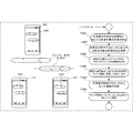
- a plant management system 100 as a first embodiment of the present invention will be described with reference to FIG.
- the plant management system 100 is a system that supports work at a work site for inspecting or maintaining a plant or the like.
- the plant management system 100 includes a measurement position instruction unit 101 and a presentation unit 102.
- the measurement position instruction unit 101 instructs a position 112 to be measured by the sensor 111 in the measurement target when measuring with the sensor at the work site 150.
- the presentation unit 102 superimposes an image indicating the position 112 to be measured by the sensor on the image of the measurement target 121 (122) or projects the image on the measurement target 121 (123). Present at work site 150.
- a measurement error can be prevented by presenting a position measured by a sensor that performs measurement for an inspection of a plant or the like when the measurement is performed.
- the plant management system according to the present embodiment collects inspection information in a management center that manages the plant. Therefore, when a worker on site carries a sensor and acquires inspection information from a predetermined position to be measured, A worker presents a plant map to a measurement target to be measured next by a worker sensor, and guides the worker. When the location of the measurement target is reached, the position of the measurement target to be measured by the worker sensor is presented superimposed on the measurement target or its image from the terminal or HMD (Head Mounted Display). Thereby, it is possible to efficiently support the work of a worker who inspects or maintains a plant or the like at the site, and prevents measurement errors.
- HMD Head Mounted Display
- AR Augmented Reality
- GPS Global Positioning System
- the position to be measured by the worker sensor is displayed.
- autonomous positioning may be combined like car navigation in a tunnel. Further, the position may be acquired by analyzing a captured image captured by the camera.
- the related information acquired by the terminal based on the operation of the worker and associated with the measurement target and the sensor information acquired by the worker sensor are stored in association with each other.
- the operation state of the measurement target is predicted based on the correspondence between the sensor information and the related information.
- the terminal for example, a head mounting display, a mobile phone, a smartphone, a tablet, or the like is used.
- the terminal may be a remote device such as a robot or a drone having a sensor function for measuring a measurement target. In that case, a remote device such as a robot or a drone is caused to perform measurement at a measurement target measurement position.
- the plant management system 300 is a system for monitoring or maintaining a structure such as a plant.
- the management center of the plant management system 300 collects sensor information acquired from a predetermined position to be measured by various types of workers' sensors while the plant operator circulates the operation of the plant, and the database 311. And monitor for abnormalities or failures. If an abnormality is recognized, the administrator 360 instructs the management center terminal 310 to analyze the sensor information stored in the database 311 and, for example, instructs the corresponding on-site worker to observe the cause of the abnormality. May be.
- the administrator 360 When an abnormality or failure is found, or when an abnormality or failure is predicted by analysis or analysis of sensor information, the administrator 360 performs a re-examination by a worker sensor from a predetermined position from the management center terminal 310. Direct maintenance work to the site.
- an on-site worker 350 determines a measurement location with reference to an identification number or symbol written at a predetermined position of each measurement target of the plant while observing a part 240 of the plant in charge regularly. Information is transmitted to the management center via communication 320. When an abnormality is recognized, a part 240 of the plant in charge is re-inspected by the worker sensor in accordance with an instruction from the manager 360 from the management center terminal 310. Further, when a maintenance work instruction is received from the management center terminal 310 by the administrator 360, the corresponding maintenance work is performed.
- the worker 350 at the site is complicated with identification numbers and symbols, and cannot accurately know the measurement location.
- Plant management system of this embodiment >> The configuration and operation of the plant management system 200 of this embodiment will be described with reference to FIGS. 2A, 2B, and 4A to 6.
- FIG. 2A is a diagram showing an outline of operation of the plant management system 200 according to the present embodiment.
- the plant management system 200 is a system for monitoring or maintaining a structure such as a plant.
- the management center of the plant management system 200 includes a plant management apparatus 210 that includes a measurement position database 211 and a measurement position providing unit 212.
- the measurement position database 211 stores a position to be measured that is associated with the type of worker sensor carried by the worker on site in each measurement target of the plant. The position to be measured is changed according to the state or change of the plant.
- the measurement position database 211 also associates the relevant information related to the measurement position with the measurement position acquired by the operator 250 at the site and the measurement position database 211 acquired by the terminal 220 carried by the worker 250. May be accumulated.
- the related information includes a captured image (or video) of the plant imaged by the terminal 220, the sound generated by the plant recorded by the terminal 220, information on the field situation input by the worker 250 to the terminal 220, and the like. .
- the measurement position providing unit 212 of the plant management apparatus 210 receives the position information of the terminal 220 carried by the worker 250 at the work site in charge, the worker 250 patrols from the position information of the terminal 220 according to the measurement schedule. Then, the measurement target to be measured is displayed as the map screen 221. On the map screen 221, the measurement target to which the worker 250 heads is indicated by a circle. When the worker 250 reaches the measurement target location, the position of the measurement target to be measured by the worker sensor 260 carried by the worker 250 is superimposed on the measurement target from the position information of the terminal 220, and the terminal 220 is displayed as a superimposed screen 222. On the superimposition screen 222, the measurement position measured by the worker 250 by the worker sensor 260 is indicated by ⁇ .
- the position to be measured by the worker sensor 260 is presented superimposed on the 3D image of the plant generated by the plant management apparatus 210 or superimposed on the image captured by the camera of the terminal 220. Presented is desirable in order to further promote the work support of the worker 250. Further, if the 3D image of the plant is an image in which the internal structure of the plant is seen through, the position to be measured can be more accurately indicated to the worker 250 at the site. Furthermore, if a 3D plant image in which the internal structure is seen through is superimposed on a captured moving image including the worker 250, it is possible to accurately guide the work target position (for example, inspection position / inspection position).
- the sensors for workers in the present embodiment include sensors for acquiring the state of the operating part and environmental information in addition to the sensor for measuring the plant itself.
- the position of the moving member or the position of the space may be presented instead of the fixed position to be measured.
- the sensor includes a temperature sensor, a humidity sensor, an atmospheric pressure sensor, an acoustic microphone or an echo microphone, a smoke sensor and an odor sensor, a vibration sensor, a speed sensor, an acceleration sensor, an infrared camera, and the like.
- the HMD which is an example of the terminal 220 is a work carried by the worker 250 based on position information from the terminal (HMD) 220 when the worker 250 approaches the measurement target in the periodic inspection, for example.
- the terminal (HMD) 220 is made to present to the operator 250 so that the position of the measurement target of the worker sensor 260 to be measured is superimposed on the measurement target plant image.
- the operator 250 can further improve the accuracy and quality of the inspection by the worker sensor 260 while confirming the internal structure in the plant if the worker sensor 260 is a fluoroscopic image. Further, the inspection report from the worker 250 with improved accuracy and quality leads to more accurate plant monitoring and failure prediction in the plant management apparatus 210.
- a report of a new inspection position or the like that a worker at the site notices from experience is reflected in the measurement position database 211, so that more efficient information collection is possible. it can.
- a new inspection position may be incorporated into the measurement schedule by analyzing at the management center from detection data including a new inspection position that the worker on site noticed from experience.
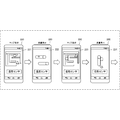
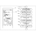
- FIG. 2B is a diagram illustrating an on-site presentation example in the plant management system 200 according to the present embodiment.
- the on-site presentation example is not limited to FIG. 2B, and other more effective combinations are possible.
- the display screen of the terminal 220 has a map screen 221 to be measured by the worker 250 on site according to the measurement schedule. Presented. On the map screen 221, the traveling direction of the worker 250 is indicated by ⁇ , and the measurement target is indicated by ⁇ .
- the work on-site is displayed on the display screen of the terminal 220 based on the position information of the terminal 220 and the identifier of the sensor 260 for the worker.
- a superimposition screen 222 in which the position that the worker 250 should measure with the worker sensor 260 is superimposed on the measurement target is presented. On the superimposition screen 222, the position to be measured by the worker sensor 260 is indicated by ⁇ .
- the measurement object to which the worker 250 on the site heads next according to the measurement schedule is displayed on the display screen of the terminal 220 based on the position information of the terminal 220 and the identifier of the sensor 260 for the worker.
- a map screen 223 shown is presented. On the map screen 223, the direction in which the worker 250 advances from the current position is indicated by ⁇ , and the next measurement target is indicated by ⁇ .
- the display screen of the terminal 220 is displayed on the site based on the position information of the terminal 220 and the identifier of the worker sensor 260.
- a superimposition screen 224 in which the position that the worker 250 should measure with the worker sensor 260 is superimposed on the measurement target is presented. On the superimposition screen 224, positions to be measured by the worker sensor 260 are indicated by ⁇ .
- FIG. 4 is a block diagram showing a functional configuration of the plant management system 200 according to the present embodiment.
- FIG. 4 shows the functional configuration of the plant management system 200 having the overall functions described in the present embodiment, but the overall functional configuration is not essential.
- the same components as those in FIG. 2A are denoted by the same reference numerals, and detailed description thereof is omitted.
- the plant management system 200 stores a measurement value acquisition unit 411 that acquires a measurement value from the worker sensor 260, and stores sensor information including the measurement value in association with the sensor ID and the measurement position ID of the worker sensor 260.
- the plant management system 200 together with the measurement position providing unit 212, provides a measurement schedule providing unit 413 that presents a measurement schedule including a measurement target map to the terminal 220 carried by the worker 250, and a measurement schedule including the measurement target map.
- a measurement schedule database 414 stored corresponding to the position information. If the measurement schedule is stored in the measurement schedule database 414 in correspondence with the terminal position information and the ID of the worker sensor 260, the measurement schedule of only the worker sensor 260 is searched.
- the measurement schedule providing unit 413 searches the measurement schedule database 414 for a measurement schedule based on the current position of the worker 250 (position information of the terminal 220). Then, the measurement schedule providing unit 413 selects a measurement schedule corresponding to the worker sensor 260 from the measurement schedule based on the sensor ID of the worker sensor 260, and the terminal 220 carried by the worker 250 along with the measurement target map. It is provided and presented to the worker 250.
- the measurement position providing unit 212 determines from the position information of the terminal 220 that the worker 250 has arrived at the measurement target, and includes a measurement position image from the measurement position database 211 based on the sensor ID of the worker sensor 260. Search for location information. Then, the measurement position providing unit 212 superimposes the measurement position image on the measurement target image captured from the camera of the terminal 220 or the measurement target 3D image generated from the plant structure, and provides the measurement position image to the terminal 220 to provide the operator. 250.
- the worker 250 refers to the superimposed image presented by the worker sensor 260 or preferably refers to the superimposed image while capturing an image including the worker sensor 260.
- 260 is set as an accurate measurement position of the measurement target.
- the worker sensor 260 transmits the sensor information including the detected measurement value to the measurement value acquisition unit 411.
- the measurement value acquisition unit 411 stores sensor information including the measurement value detected by the worker sensor 260 in the sensor information database 412 in association with the sensor ID of the worker sensor 260 and the measurement position ID thereof.
- the accumulated sensor information may be presented together with the terminal 220 when the measurement schedule or the measurement position is provided to the terminal 220 or when the worker sensor 260 detects the measurement target measurement position.
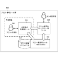
- FIG. 5A is a block diagram illustrating a hardware configuration of the plant management system 200 according to the present embodiment.
- Each device of the plant management system 200 is a device having a processor (CPU: Central Processing Unit) and a memory, and the function of each unit of the device is obtained as a result of the processor executing a program stored in the memory. .
- processor Central Processing Unit
- the plant management system 200 includes a plant management device 210 that manages plants connected via a network 540, and a site management device 560 that manages sites.
- the network 540 is a network configured across the entire plant or between a plurality of plants, and may be configured via the Internet using a VPN (Virtual Private Network) or the like.
- the network 540 may be wired / wireless.
- the plant management apparatus 210 includes a workflow apparatus 510 and a data management apparatus 530.
- the workflow device 510 includes at least an alarm transmission / reception unit 511, a workflow control unit 512, and an input / output control unit 513.
- the alarm transmission / reception unit 511 includes a function of receiving an alarm generated outside and transmitting an alarm to the outside.
- the workflow control unit 512 controls a workflow in accordance with a predetermined notation or standard (for example, ISA (International Society of Automation) -95).
- the input / output control unit 513 controls data input / output in accordance with alarm transmission / reception and workflow control.
- the workflow apparatus 510 may further include a task list unit that performs control related to display of a task list to the user and an instruction to input a work result from the user.
- the data management device 530 includes an HMI (Human Machine Interface) function and a SCADA (Supervisory Control And Data Acquisition) function, collects and stores data related to the plant, and serves as an interface with the management of the plant manager.
- the data management device 530 includes at least a data collection unit 531, a data storage unit 532, and a process control unit 533.
- the data collection unit 531 includes a data collection unit 531 and a process control unit 533. Collects data detected by the sensor and data transmitted from other devices, and a data accumulation unit 532 accumulates the data collected by the data collection unit 531 in a searchable and analyzable manner. Analyzes the data stored in the data storage unit 532 and responds to the analysis result with the plant profile. Perform Seth control.
- the site management device 560 includes a terminal 220 carried by the worker 250 and a worker sensor 260 for the worker 250 to measure a measurement target.
- the terminal 220 includes at least an input / output control unit 521, an audio input / output unit 522, and a display unit 523.
- the input / output control unit 521 inputs the plant image on which the task list and sensor information displayed on the display unit 523 are superimposed or the audio data output from the speaker of the audio input / output unit 522 via the network 540. Control the input of. Further, the input / output control unit 521 outputs the current position information of the terminal 220 and the image information captured by the camera via the network 540, or outputs the audio data collected by the microphone of the audio input / output unit 522. Control.
- the voice input / output unit 522 includes a microphone and a speaker.
- the display unit 523 includes a touch panel operation unit, displays a plant image on which a task list and sensor information are superimposed in relation to the present embodiment, and performs operations such as work-related information input, camera operation, and recording operation. To realize. Note that the transmission of the position information from the terminal 220 includes a case where the plant management apparatus 210 periodically collects and a case where the position information is transmitted by an operation of the worker 250 at the time of emergency.
- the worker sensor 260 includes at least an input / output control unit 541, a notification information processing unit 542, and a detection unit 543.
- the input / output control unit 541 controls the operation of the worker sensor 260 via the network 540 or the input when the worker sensor 260 is operated by firmware.
- the input / output control unit 541 controls the output of detection data detected by the detection unit 543 or the output of sensor information including information on the worker sensor 260 via the network 540.
- the notification information processing unit 542 performs processing when processing is required for the detection data detected by the detection unit 543 or when processing for output via the network 540 is required. Therefore, when the worker sensor 260 simply outputs the detection data detected by the detection unit 543 as it is, it may be omitted.
- the alarm transmission / reception unit 511 receives position information, image information, audio information, and the like from the terminal 220 carried by the worker 250 in the field, and determines that the alarm is one of new workflow activation alarms. The result is transmitted to the workflow control unit 512.
- the workflow control unit 512 is characterized by the procedure of starting a workflow that presents a map for heading the measurement target to the terminal 220 carried by the worker 250 on site and a position to be measured of the measurement target. Realized the function.
- the present invention is not limited to a solution that changes the configuration of the alarm transmission / reception unit 511 or the workflow control unit 512.
- the location information, image information, audio information, and the like are received from the terminal 220 carried by the site worker 250, and the map and the measurement target are measured to the terminal 220 carried by the site worker 250. It may be realized by adding a new function configuration unit or a new workflow that presents the position to be, or may be realized by providing another dedicated device.
- FIG. 5B is a block diagram showing a software configuration of the plant management system 200 according to the present embodiment.
- FIG. 5B shows the minimum configuration for realizing the plant management system 200.
- the addition of other software tools, the subdivision of the illustrated software tools, the overlapping of a plurality of software tools, and the like are illustrated. It has not been.
- the plant management tool group 550 in FIG. 5B manages at least a terminal tool 551 for a worker who defines and manages processing related to the terminal 220 that the plant worker 250 carries while working on site. It has a plant operation workflow tool 552 related to the plant operation by the manager of the center, and a plant monitoring tool 553 that collects data including sensor information and monitors the plant operation.
- the plant monitoring tool 553 registers the facilities that make up the plant, analyzes the information in the plant facility database 554 that accumulates the driving history, and monitors the plant operation to detect and predict failures and prevent them from occurring.
- Generate maintenance work for While referring to the output information from the plant monitoring tool 553, on-site observation and maintenance work and center management work are generated in the operator terminal tool 551 and the plant operation workflow tool 552.
- the position information of the terminal 220 carried by the worker 250 at the site and the work carried by the worker 250 are obtained by the cooperation of the plant operation workflow tool 552 and the worker terminal tool 551.
- the measurement sensor and the position to be measured are selected by the operator sensor 260 and presented from the terminal 220 to the worker 250 on site. Further, referring to the measurement object presented on the terminal 220 and the position to be measured, the result of the measurement by the worker sensor 260 appropriately performed by the worker 250 at the site is accumulated in the plant facility database 554. Then, analysis is performed by the plant monitoring tool 553, and further observation maintenance work for the next site and management work for the center are generated.
- the improved collection of sensor information by the on-site worker 250, the information from the on-site worker 250, can be incorporated into plant management more effectively.
- FIG. 5C is a diagram showing a workflow of the plant management system 200 according to the present embodiment. Note that FIG. 5C is an overall workflow using all the components of the plant management system 200, and is different from the work workflow corresponding to each work described below. Moreover, the workflow of the plant management system 200 is not limited to FIG. 5C.
- the plant management system 200 instructs the terminal 220 of the worker 250 to perform monitoring work or inspection work in task T501.
- the plant management system 200 acquires the position information of the terminal 220 of the worker 250 on site.
- the plant management system 200 generates a measurement target image corresponding to the position information of the terminal 220 of the worker 250 from an image captured by the camera of the terminal 220 or a 3D image generated from plant configuration data. As to get.
- the plant management system 200 acquires the measurement position of the measurement target corresponding to the worker sensor 260 possessed by the worker 250 from the measurement position database 211.
- the plant management system 200 superimposes the measurement position on the measurement target image and presents it on the terminal 220 in task T509. If necessary, the plant management system 200 presents past sensor information and normal sensor information to the terminal 220 in task T511. In task T513, the plant management system 200 acquires sensor information of a position to be measured from the worker sensor 260 possessed by the worker 250.
- the plant management system 200 waits for confirmation whether the acquisition of the sensor information of the position to be measured from the worker sensor 260 in task T513 is correct detection or detection error. Such confirmation of measurement may be executed by starting a new workflow. If the measurement confirmation is obtained, the plant management system 200 accumulates sensor information in association with the sensor ID and the measurement position of the worker sensor 260 in task T517.
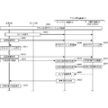
- FIG. 6 is a sequence diagram showing an operation procedure of the plant management system 200 according to the present embodiment.
- FIG. 6 shows an operation procedure of superimposed presentation in which an image of a measurement position is superimposed on an image to be measured based on position information of a terminal corresponding to FIG.
- step S601 the terminal device 220, the sensor 230, the workflow device 510 and the data management device 530 included in the plant management device 210 activate the plant management application.
- the plant management application does not need to be a single program, and may be configured by a plurality of program tool groups. In that case, it is not necessary for all the components to start the plant management application at the same time, and they may be started when entering the plant management system 200.
- the terminal 220 logs in to connect to the plant management apparatus 210, and the plant management apparatus 210 accepts the login and registers.
- step S603 the worker sensor 260 or the terminal 220 transmits the sensor ID of the worker sensor 260 to the workflow device 510 and the data management device 530 of the plant management device 210. Further, in step S605, the terminal 220 acquires current position information and transmits it to the workflow device 510 and the data management device 530 of the plant management device 210. In step S607, the data management apparatus 530 refers to the current position information from the terminal 220, searches for the measurement schedule, and transmits it to the workflow apparatus 510. When the workflow apparatus 510 acquires the measurement schedule in step S ⁇ b> 609, the workflow apparatus 510 refers to the sensor ID of the worker sensor 260 and transmits the measurement schedule related to the worker sensor 260 to the terminal 220.
- step S611 the terminal 220 presents the measurement schedule related to the received worker sensor 260 to the worker 250.
- the workflow device 510 selects the measurement schedule related to the worker sensor 260
- the data management device 530 may select the measurement schedule with reference to the sensor ID of the worker sensor 260.
- the terminal 220 acquires current position information in step S613, and performs plant management.
- the information is transmitted to the workflow device 510 and the data management device 530 of the device 210.
- the terminal 220 captures the measurement target with the camera and transmits it to the workflow device 510 in step S615.
- the data management apparatus 530 searches for the 3D plant image of the measurement target corresponding to the position information from the terminal 220 in step S617, and the workflow apparatus 510.
- step S619 the workflow apparatus 510 acquires an image to be measured.
- step S ⁇ b> 621 the data management apparatus 530 searches for an image of the measurement position in the measurement target corresponding to the position information from the terminal 220 and transmits the image to the workflow apparatus 510.
- step S623 the workflow apparatus 510 acquires an image of the measurement position in the measurement target.
- the workflow apparatus 510 may acquire past or normal sensor information corresponding to the sensor ID and measurement position of the worker sensor 260 from the data management apparatus 530 in step S625.
- step S627 the workflow apparatus 510 superimposes the image of the measurement position on the measurement target image, and further superimposes past or normal sensor information if necessary, and transmits it to the terminal 220 of the worker 250. To do.
- the terminal 220 of the worker 250 receives the superimposed image and presents it to the worker 250 in step S629.
- the terminal 220 is an optical see-through HMD
- the image at the measurement position is presented to the optical see-through HMD so as to be superimposed on the actual measurement target.
- FIG. 7A is a block diagram illustrating a functional configuration of the alarm transmission / reception unit 511 according to the present embodiment.
- the alarm transmission / reception unit 511 includes a function of receiving an alarm generated outside and transmitting an alarm to the outside.
- the position information of the terminal 220, the image information or audio information from the terminal 220, etc. are determined to be received as an alarm, and the measurement target map corresponding to the worker sensor is sent to the workflow control unit 512.
- an alarm for starting a workflow for presenting the measurement position of the measurement target to be measured by the worker sensor to the terminal 220.
- the alarm transmission / reception unit 511 includes a communication control unit 701, a position information reception unit 702, an imaging information reception unit 703, a voice information reception unit 704, an alarm reception unit 705, and an alarm determination unit 706.
- the alarm determination unit 706 has an alarm determination table 707.
- the alarm transmission / reception unit 511 further includes an alarm information providing unit 708 and an alarm transmission unit 709.
- the communication control unit 701 controls communication with the workflow control unit 512 and the input / output control unit 513 of the same workflow device 510. Further, the communication control unit 701 controls communication with the data management device 530.
- the position information receiving unit 702 receives the position information of the terminal 220 from the terminal 220 via the input / output control unit 513 and the communication control unit 701.
- the imaging information receiving unit 703 receives imaging information captured by the terminal 220 from the terminal 220 via the input / output control unit 513 and the communication control unit 701.
- the audio information receiving unit 704 receives audio information recorded by the terminal 220 from the terminal 220 via the input / output control unit 513 and the communication control unit 701.
- the alarm receiving unit 705 receives various alarms from the components of the plant management system 200 via the communication control unit 701.
- the alarm determination unit 706 determines the alarm contents and the alarm destination by using the alarm determination table 707 based on the information received by the receiving units 702 to 705.
- the alarm information providing unit 708 provides the information determined by the alarm determination unit 706 to the alarm destination.
- position information, imaging information, audio information, and the like are provided to the workflow control unit 512 that is an alarm destination.
- the alarm transmission unit 709 provides an alarm signal or alarm type to the alarm destination.
- the alarm transmission unit 709 instructs the workflow control unit 512 to start the workflow
- the alarm information providing unit 708 instructs the workflow control unit 512 to select conditions such as position information, imaging information, and audio information for selecting the workflow. Is provided.
- FIG. 7B is a diagram showing a configuration of the alarm determination table 707 according to the present embodiment.
- the alarm determination table 707 is used to determine whether or not to output an alarm signal based on information received by the alarm determination unit 706.
- the alarm determination table 707 includes reception information 771, determination information 772 for determining whether or not the reception information corresponds to alarm transmission, a determination result 773 for whether or not to transmit an alarm, and an alarm notification when an alarm is transmitted.
- the destination 774 is stored.
- the reception information 771 includes position information, imaging information, audio information, and other reception information.
- the determination information 772 includes a determination condition of position information from the terminal 220, imaging information from the terminal 220, or audio information from the terminal 220.
- FIG. 7C is a flowchart illustrating an operation procedure of the alarm transmission / reception unit 511 according to the present embodiment.
- the flowchart is executed by the processor of the workflow device 510 or the alarm transmission / reception unit 511 using the memory, and as a result, each functional component shown in FIG. 7A is obtained.
- the processor of the workflow device 510 executes.
- the workflow apparatus 510 receives information in step S701. In step S703, the workflow apparatus 510 determines whether to issue an alarm based on the received information. In the present embodiment, it is determined whether or not the received information is position information, imaging information, and audio information from the terminal 220. If the conditions are satisfied, an alarm is transmitted to communicate the activation of the workflow to the workflow control unit 512. .
- step S705 the workflow apparatus 510 determines whether the alarm notification destination is the workflow control unit 512 or the like. If the alarm notification destination is the workflow control unit 512, the workflow apparatus 510 notifies the workflow control unit 512 of the alarm signal and the reception information in step S707. On the other hand, if it is another notification destination, the workflow apparatus 510 notifies the other notification destination of an alarm in step S709.
- FIG. 8A is a block diagram illustrating a functional configuration of the workflow control unit 512 according to the present embodiment.
- the workflow control unit 512 controls a workflow in accordance with a predetermined notation and standard, for example, ISA-95.
- an alarm that functions as a workflow is received from the alarm transmission / reception unit 511 together with position information of the terminal 220, image information or audio information from the terminal 220, and the corresponding workflow is activated.
- the sensor 260 for the worker is used.
- a sensor ID is used.
- the workflow control unit 512 includes a communication control unit 801, an alarm reception unit 802, a worker sensor ID reception unit 803, a terminal ID reception unit 804, an alarm information reception unit 805, and a workflow activation unit 806. .
- the workflow activation unit 806 has a workflow activation table 807.
- the workflow control unit 512 further includes a workflow instruction unit 808. The instruction by the workflow instruction unit 808 realizes the processing of the measurement position providing unit 212.
- the communication control unit 801 controls communication with the alarm transmission / reception unit 511 and the input / output control unit 513 of the same workflow device 510.
- the communication control unit 801 controls communication with the administrator terminal of the management center.
- the alarm receiver 802 receives the alarm of this embodiment from the alarm transmitter / receiver 511.
- the worker sensor ID receiving unit 803 receives the sensor ID of the worker sensor 260 in order to select and present the measurement position in the database.
- the terminal ID receiving unit 804 receives the terminal ID of the terminal that presents the measurement position in a superimposed manner.
- the alarm information receiving unit 805 receives alarm information (parameters used in a workflow to be activated) transmitted by the alarm information providing unit 708 of the alarm transmitting / receiving unit 511.
- the workflow activation unit 806 selects a workflow to be activated and parameters to be used based on the workflow activation table 807 based on the information received by the receiving units 802 to 805.
- the workflow instruction unit 808 instructs the corresponding component of the plant management system 200 to start the workflow selected by the workflow starting unit 806 using parameters.
- a workflow corresponding to the alarm information is selected from the workflows that present the measurement position to the terminal 220 of the worker 250 based on the information received by the receiving units 802 to 805, and the worker sensor ID, terminal ID, and alarm information are added as parameters and activated.
- FIG. 8B is a diagram showing a configuration of the workflow activation table 807 according to the present embodiment.
- the workflow activation table 807 is used to select a workflow to be activated from the alarm received from the alarm transmission / reception unit 511 and each received information.
- the workflow activation table 807 stores a workflow ID 873 to be activated that is selected based on the reception information 871 and the workflow activation condition 872. Furthermore, the workflow ID 873 to be activated is designated as a pointer, and the workflow 875 is selected from a table that stores the workflow ID 874 and the workflow 875 in association with each other.
- the reception information 871 includes the received alarm, worker sensor ID, terminal ID, and alarm information.
- the workflow activation condition 872 includes an alarm, a worker sensor ID, a terminal ID, and alarm information as conditions for selecting a workflow to be activated from the reception information 871.
- FIG. 8C is a flowchart showing an operation procedure of the workflow control unit 512 according to the present embodiment. This flowchart is executed by the processor of the workflow device 510 or the workflow control unit 512 using the memory, and as a result, each functional component of FIG. 8A is obtained. In the following description, it is assumed that the processor of the workflow device 510 executes.
- the workflow apparatus 510 receives information in step S801. In step S803, the workflow apparatus 510 determines a workflow to be activated based on the received information. In the present embodiment, a workflow group that superimposes the image of the measurement position on the measurement target image and presents it to the terminal is selected from the received alarm. A workflow corresponding to the processing content, presentation format, etc. is selected from the worker sensor ID and the terminal ID. Furthermore, the workflow information corresponding to the presentation method may be narrowed down from alarm information including position information, imaging information, and audio information.
- step S805 the workflow apparatus 510 determines whether or not the selected workflow is presentation of a measurement position superimposed on the measurement target image on the terminal. If the measurement position is presented to the terminal, the workflow apparatus 510 activates a workflow for presenting the measurement position to the terminal at the site in step S807. On the other hand, if the workflow is another workflow, the workflow apparatus 510 activates the other workflow in step S809.
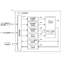
- FIG. 9A is a block diagram illustrating a functional configuration of the data storage unit 532 according to the present embodiment.
- the data storage unit 532 is in the data management device 530 and stores the data collected by the data collection unit 531.
- a measurement schedule, a plant structure to be measured, a position to be measured, and the like to be measured are stored in the measurement position database 211 corresponding to the position information of the terminal and the sensor ID for the worker, and the measurement target database This is used to generate a superimposed image in which a position to be measured is superimposed on the image.
- the data storage unit 532 includes a communication control unit 901, an alarm reception unit 902, a sensor information reception unit 903, a terminal information reception unit 904, a worker sensor ID reception unit 905, and a measurement position database 211. .
- the measurement position database 211 has a data accumulation table 906.
- the data storage unit 532 further includes a plant equipment database 554, a data analysis algorithm database 908, and an information providing unit 909.
- the communication control unit 901 controls communication between the data collection unit 531 and the process control unit 533 of the same data management device 530.
- the alarm receiving unit 902 receives an alarm generated in the plant management system 200.
- the sensor information receiving unit 903 receives the sensor information detected by the worker sensor in association with the sensor ID.
- the terminal information receiving unit 904 receives terminal information acquired and transmitted by each terminal.
- the terminal information includes position information of the terminal and a measurement target ID that identifies a measurement target corresponding to the position.
- the worker sensor ID receiving unit 905 receives a sensor ID for identifying the worker sensor 260 for searching the measurement position of the measurement target corresponding to the worker sensor.
- the measurement position database 211 stores the measurement schedule, the plant structure of the measurement target, the position of the measurement target to be measured, and the like in a searchable manner corresponding to the terminal position information and the worker sensor ID.
- the plant equipment database 554 stores equipment information constituting the managed plant.
- the data analysis algorithm database 908 stores a data analysis algorithm that performs abnormality diagnosis, prediction, or maintenance operation while combining sensor information accumulated in the sensor information database 412 with related information.
- the information providing unit 909 displays information necessary for presentation of the measurement position superimposed on the measurement target to the terminal, generation of a 3D plant image from the plant facility information, or data analysis by the process control unit 533 in each database 211, Obtained from 554 or 908 and provided.
- FIG. 9B is a diagram showing a configuration of the data accumulation table 906 according to the present embodiment.
- the data accumulation table 906 is used to store the measurement schedule, the plant structure of the measurement target, the position of the measurement target to be measured, and the like in a searchable manner corresponding to the terminal position information and the worker sensor ID.
- the data accumulation table 906 stores plant position IDs 962 of a plurality of partial plants corresponding to each plant ID 961. Further, the ID 963 of the worker sensor 260 carried by the worker 250 for detection is stored corresponding to each plant position ID 962. And the measurement position 964 which is a position which should be measured with the sensor 260 for workers in each plant position (measurement object) is memorize
- a plurality of detection dates 974 are stored in association with each measurement position 964.
- a detection time 975, detected sensor information 976, and additional information 977 including related information are stored.
- the additional information 977 includes alarm information when the sensor information 976 is acquired, captured images and sounds acquired by the on-site terminal as related information, sensor information 976 detected currently, or accumulated past sensor information. Analysis results based on it are included.
- the data accumulation table 906 stores the measurement position 984 corresponding to the combination of the measurement schedule ID 981, the worker ID 982, and the worker sensor ID 983 for identifying the measurement schedule. In some cases, the worker ID 982 may not be considered.
- FIG. 9C is a flowchart showing an operation procedure of the data storage unit 532 according to the present embodiment. This flowchart is executed by the processor of the data management device 530 or the data storage unit 532 using the memory, and as a result, each functional component shown in FIG. 9A is obtained. In the following description, it is assumed that the processor of the data management device 530 executes.
- step S911 the data management device 530 determines whether information has been received. If the information is received, the data management device 530 determines whether there is additional information such as related information associated with the sensor information in step S913. If there is additional information, the data management device 530 adds additional information such as related information to the sensor information so that it can be searched or analyzed in step S915. In step S917, the data management device 530 accumulates the sensor information or the sensor information to which the additional information is added in the format shown in FIG. 9B in the sensor information database 412.
- step S921 the data management device 530 determines whether or not it is a request for information from another device or other functional component of the plant management system 200. In the case of requesting information, in step S923, the data management device 530 searches the measurement position database 211 for the measurement position to be superimposed on the measurement object, the measurement target determined from the terminal position information, the worker sensor, and the like. The search key is obtained from the information requester. In step S925, the data management device 530 searches for data from the measurement position database 211 using the acquired search key. In step S927, the data management device 530 provides the retrieved data to the information requester.
- the measurement position to be superimposed and displayed on the measurement target corresponding to the terminal position is searched.
- the workflow is to superimpose the measurement position on the captured image of the plant, an image of the measurement position is provided, or if the workflow is presentation to the optical see-through HMD, the plant structure information is further generated as a 3D image.
- FIG. 10 is a diagram showing a work workflow according to the present embodiment.
- the workflow in FIG. 10 is a new workflow that describes a processing portion that superimposes and presents an image of a measurement position on an image to be measured on a terminal in the field in the present embodiment.
- the workflow shown below shows a work procedure performed by the workflow device 510 using each component device and each function component of the plant management system.
- FIG. 10 shows only the minimum basic tasks of the present embodiment, and various tasks may be added.
- the workflow device 510 acquires an image to be measured corresponding to the position information of the terminal 220 carried by the worker 250 in the field in task T1001.
- the workflow apparatus 510 acquires the measurement position of the measurement target corresponding to the worker sensor 260 possessed by the worker 250.
- the workflow apparatus 510 superimposes the measurement position image on the measurement target image and presents it on the terminal 220 carried by the worker 250 on site.
- the workflow apparatus 510 acquires sensor information from the worker sensor 260 set as a measurement target with reference to the presentation of the measurement position by the worker 250 in the field.
- the workflow apparatus 510 stores sensor information and acquired information such as related information from the terminal 220 in association with each other so as to be searchable based on the sensor ID of the worker sensor 260 and the measurement position.
- the measurement position of the sensor for the worker at the work site is presented to the worker, and the work on the site of the worker who checks or maintains the structure such as a plant is more efficiently supported.
- a measurement error can be prevented by accurately presenting to the worker the position measured by the sensor that performs measurement for the inspection of the plant or the like.
- the operator can collect accurate sensor information with the sensor for the worker at the site, and the operator can flexibly add or change the measurement position taking into account observation and experience information. Can be monitored efficiently.
- the plant management system according to the present embodiment differs from the second embodiment in that the measurement position is projected and presented to the worker at the work site. It is desirable to project the measurement position directly on the measurement target of the plant.However, the image of the measurement target and the measurement position are placed in a place where the operator can clearly recognize the measurement position of the measurement target. The image may be superimposed and projected.
- the projection device a projection device such as a laser or a projection is used.
- the measurement position may be projected from a wristband or goggles, in addition to a fixed-position device such as a ceiling. Since other configurations and operations are the same as those of the second embodiment, the same configurations and operations are denoted by the same reference numerals, and detailed description thereof is omitted.
- Plant management system The configuration and operation of the plant management system 1100 of this embodiment will be described with reference to FIGS. 11A to 14.
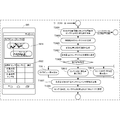
- FIG. 11A is a diagram illustrating an operation outline of the plant management system 1100 according to the present embodiment.
- the same components as those in FIG. 2A are denoted by the same reference numerals, and redundant description is omitted.
- the plant management apparatus 1110 includes a measurement position providing unit 1112 and a measurement / projection unit position database 1111.
- the measurement position providing unit 1112 acquires current position information from the terminal 220 carried by the worker 250 on site
- the measurement position providing unit 1112 should measure the worker sensor 260 with reference to the worker sensor 260 possessed by the worker 250.
- the measurement position of the measurement target is selected, and the measurement position is projected from the projector as the projection device 1150 onto a part 240 of the plant to be measured.
- the measurement / projection unit position database 1111 stores the position of the projection unit 1150 to be selected based on the current position information from the terminal 220 carried by the worker 250 on site along with the measurement position.
- a message to the worker 250 of the measurement presentation position 241 and “Please apply the vibration sensor for 5 seconds” is projected on a part 240 of the plant.
- FIG. 11B is a diagram showing another operation outline of the plant management system 1100 according to the present embodiment.
- the same components as those in FIG. 2A or FIG. 11A are denoted by the same reference numerals, and redundant description is omitted.
- the projector as the projection device 1150 superimposes the measurement presentation position 1171 on the image 1140 of the part of the plant to be measured corresponding to the current position information of the terminal 220 on the site, and projects it onto the screen 1170.
- the measurement presentation position 1171 is superimposed and projected on the captured image including the worker sensor 260 that approaches the measurement position of the part 240 of the plant to be measured. This can be done while confirming the setting to the measurement position.
- FIG. 12 is a block diagram showing a functional configuration of the plant management system 1100 according to the present embodiment.
- the same components as those in FIG. 4 are denoted by the same reference numerals, and redundant description is omitted.
- the measurement position providing unit 1112 of the plant management system 1100 acquires the measurement position and the projection unit position stored in the measurement / projection unit position database 1111. Then, the measurement position providing unit 1112 obtains the projection unit ID of the projection unit when corresponding from the current position information of the terminal 220, and projects the measurement position from the projection unit 1150 onto the measurement target. Alternatively, the measurement position image is superimposed on the measurement target image and projected onto the screen.
- the near field communication (for example, beacon etc.) between the terminal 220 and the projection part 1150 on the spot may be a trigger, and the projection process in the field of the measurement position of this embodiment may be started.
- the terminal 220 may not be a high-function device such as a smartphone or a tablet, but may be a device having only a short-range communication function, and a plant image on which the measurement position is superimposed is generated based on the plant equipment. A 3D plant image in which the created internal structure is seen through is used.
- FIG. 13 is a block diagram showing a hardware configuration of the plant management system 1100 according to the present embodiment.
- the same functional components as those in FIG. 5A are denoted by the same reference numerals, and redundant description is omitted.
- the plant management system 1100 includes a plant management device 1110 and a site management device 1360 connected via a network 540.
- the workflow device 1310 constituting the plant management device 1110 activates a workflow for projecting sensor information onto a projection device such as a projector, which is the projection device 1150 as the presentation device of the present embodiment.
- the site management device 1360 includes a terminal 220, a worker sensor 260, and a projection device 1150 as a presentation device connected via a network 540.
- the projection device 1150 includes an input / output control unit 1351 that controls input / output with other devices, and a projection unit 1353 that projects an image in which sensor information or sensor information is superimposed on a plant image.
- the input / output control unit 1351 controls input of an image in which the measurement position is superimposed on the measurement position or the plant image. Further, in the case of a short distance between the terminal 220 and the projection unit 1150, short distance communication is performed.
- FIG. 14 is a sequence diagram showing an operation procedure of the plant management system 1100 according to the present embodiment.
- the same steps as those in FIG. 6 are denoted by the same step numbers, and redundant description is omitted.
- step S1424 the data management device 530 searches for the ID of the projection unit corresponding to the current position information acquired from the terminal 220 on site, and provides it to the workflow device 1310.
- the workflow device 1310 acquires the projection unit ID in step S1425, generates measurement position information in step S1427, and transmits the measurement position information to the projection unit 1150 having the projection unit ID.
- step S ⁇ b> 1429 the projection unit 1150 projects the received measurement position image onto the measurement target plant and presents it to the operator 250.
- FIG. 15 is a diagram showing a work workflow according to the present embodiment.
- the same task number is assigned to the same task as in FIG. 10, and redundant description is omitted.
- the workflow apparatus 510 projects an image of the measurement position on the measurement target from the projection unit 1150 corresponding to the position information from the terminal 220 on the site, and presents it to the worker 250 on the site.
- the projection apparatus having the projection function is arranged on the site, it is possible to efficiently perform the work on the site of an operator who inspects or maintains a structure such as a plant without carrying a predetermined device. Can help. That is, it is not necessary to carry the terminal.
- FIG. 16A is a diagram illustrating an operation outline of the plant management system 1600 according to the present embodiment.
- FIG. 16A illustrates the minimum two cases as a plurality, but the configuration and processing are the same for three or more.
- the same components as those in FIG. 2A are denoted by the same reference numerals, and redundant description is omitted.
- two terminals are terminals 22A and 22B
- two workers are workers 25A and 25B
- two worker sensors are worker sensors 26A and 26B. 250 and the worker sensor 260 are the same.
- the plant management apparatus 1610 associates the measurement position database 1611 for storing information that corresponds to the measurement by the plurality of worker sensors 26A and 26B, and the measurement by the plurality of worker sensors 26A and 26B, A measurement position providing unit 1612 for presenting the measurement position;
- the worker 25A possessing the terminal 22A and the worker sensor 26A is about to perform measurement by the worker sensor 26A at the measurement presentation position 241 of the part 240 of the plant according to the measurement schedule.
- the worker 25B possessing the terminal 22B and the worker sensor 26B intends to perform measurement by the worker sensor 26B at the measurement presentation position 242 of the part 240 of the plant according to the measurement schedule.
- the measurement presentation position 241 measured by the worker sensor 26A superimposed on the image of the part 240 of the plant is presented, and the measurement time is instructed to be 15:00. Yes.
- the measurement presentation position 242 measured by the worker sensor 26B superimposed on the image of the plant part 240 is presented, and the measurement time is 15:15. It is instructed.
- the measurement time at the measurement presentation position 242 is preferably 15 seconds later than the measurement time at the measurement presentation position 241.
- the presentation contents of the case are shown. According to the present embodiment, it is possible to adjust the timing of more measurements and adjust the timing between different sensors by setting the presentation content.
- the measurement time is set to one point, but the measurement time zone may be presented within an allowable range.
- the same measurement target image is displayed on the screens of the terminals 22A and 22B, but when the workers 25A and 25B are separated, different measurement target images are displayed. Is done.
- FIG. 16B is a sequence diagram showing an operation procedure of the plant management system 1600 according to the present embodiment. In FIG. 16B, the same steps as those in FIG. 6 or FIG.
- FIG. 16B the processing of the terminal 22A and the worker sensor 26A is shown in steps S603 to S629 similar to FIG. 6, and the processing corresponding to FIG. 6 of the processing of the terminal 22B and the worker sensor 26B is performed in step S1603.
- steps S603 to S629 similar to FIG. 6, and the processing corresponding to FIG. 6 of the processing of the terminal 22B and the worker sensor 26B is performed in step S1603.
- the processing of the step number having the same last two digits is the same. Therefore, description of these steps S1603 to S1629 is also omitted.
- the respective processes are collectively shown as, for example, steps S603 and S1603, but generally data transmission is performed at separate timings.
- step S1617 the data management device 1630 refers to the location information of each terminal, searches for a 3D image to be measured at each location, and transmits the 3D image to the workflow device 1620.
- step S ⁇ b> 1619 the workflow device 1620 obtains a measurement target captured image from each of the terminals 22 ⁇ / b> A and 22 ⁇ / b> B or a measurement target 3D image from the data management device 1630.
- step S1621 the data management apparatus 1630 refers to the position information of each terminal, searches for the measurement position image of each measurement target, and transmits it to the workflow apparatus 1620.
- step S ⁇ b> 1623 the workflow device 1620 acquires an image of the measurement position from the data management device 1630.
- step S ⁇ b> 1627 the workflow device 1620 superimposes the measurement position image corresponding to the worker sensor on the captured image or 3D image to be measured. Furthermore, when there is a relationship between the measurement times by the workers' sensors 26A and 26B at the respective measurement positions, the desired measurement times are superimposed on each other and presented. 16B shows an example in which the workflow device 1620 selects the measurement position corresponding to the worker sensor. However, the data management device 1630 selects the measurement position corresponding to the worker sensor. Also good.
- Sensor information measured at the presented timing by the workers' sensors 26A and 26B is collected, accumulated, and analyzed in the workflow device 1620 and the data management device 1630 in step S1631.
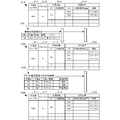
- FIG. 17 is a diagram showing a configuration of the data accumulation table 1706 according to the present embodiment.
- the same reference numerals are given to the same components as those in FIG. 9B, and duplicate descriptions are omitted.
- the measurement time 1785 and the measurement time range 1786 are stored in association with each of the measurement positions 984 selected by combining the measurement schedule ID 981, the worker ID 982, and the worker sensor ID 983. Then, the measurement time 1785 and the measurement time range 1786 are presented to each terminal that requires measurement timing adjustment by the worker sensor. In the present embodiment, the measurement time is presented to each terminal. However, when only the relationship between the measurement times is important, timing adjustment may be performed in which the next measurement time is presented after the previous measurement is completed.
- FIG. 18 is a diagram showing a workflow of the plant management system 1600 according to the present embodiment.
- the same two-digit task number as that of each task in FIG. 5C is the same as the contents of the process, except that each worker is at the head or each sensor information. Therefore, the overlapping description is omitted.
- Plant management system 1600 acquires the measurement timing in relation to the worker sensor possessed by each worker in task T1808.
- the measurement timing is adjusted by presenting the time.
- it may be expressed by a change in an identifiable measurement position, for example, color, density, shape, or the like.
- adjustment by sound, control of the measurable time of the worker sensor, and the like may be used.
- the present embodiment when measurement is performed with a plurality of workers' sensors, when there is a timing relationship in measurement at each measurement position, information for timing adjustment is presented from the terminal. Sensor information collection that enables more precise monitoring and analysis becomes possible.
- the plant management system according to the present embodiment does not superimpose or project an image indicating the measurement position, but the operator sensor sets the measurement position as the measurement target. The image being measured is superimposed or projected. Then, it is different in that accurate setting including the direction to the measurement position is possible by superimposing the actual worker sensor on the image of the worker sensor. Since other configurations and operations are the same as those in the second to fourth embodiments, the same configurations and operations are denoted by the same reference numerals, and detailed description thereof is omitted.
- FIG. 19 is a diagram showing an outline of the operation of the plant management system 1900 according to the present embodiment.
- the plant management apparatus 1910 of the plant management system 1900 includes a measurement position / sensor shape database 1911 and a measurement position providing unit 1912.
- the measurement position providing unit 1912 acquires the sensor shape of the worker sensor 260 from the measurement position / sensor shape database 1911 together with the measurement position. Then, an image of the sensor shape of the worker sensor 260 is superimposed on the measurement target in the direction actually set at the measurement presentation position at the worker sensor 260.
- the worker 250 sets the worker sensor 260 at a position where the captured image of the actual sensor indicated by the solid line exactly overlaps the broken sensor shape image as in the display screen 1921.
- the operator sensor 260 is set at a position where the actual sensor indicated by the solid line exactly overlaps the broken line sensor shape image projected onto the measurement target, as in the display screen 1951.
- the operator sensor can be easily set to the measurement presentation position with its orientation and direction set in a simple manner, and measurement data can be collected with no more measurement errors.
- the plant management system according to the present embodiment is different from the second to fifth embodiments in that the worker support is provided by adding a different measurement position presentation method and an operation method from the worker. Since other configurations and operations are the same as those in the second to fifth embodiments, the same configurations and operations are denoted by the same reference numerals, and detailed description thereof is omitted.
- FIG. 20 is a diagram illustrating a first presentation example on site and a corresponding workflow in the plant management system according to the present embodiment.
- the method of holding the terminal 220 at the time of superimposing the sensor information and the line of sight of viewing the plant of the worker 250 may be related, and a completely straight transparent image on the screen may be presented. There is also a way of checking the superimposed image while visually observing the actual product. In this case, an image with a slight angle up or down may be presented instead of a straight perspective direction.
- the front facilities are presented as if viewed from the front. Note that this is not possible with an ordinary tablet camera, but it is possible to use a device whose camera orientation is corrected upward or downward.
- the left diagram of FIG. 20 shows a plant display 2021 when the worker 250 is looking at the plant from the top to the bottom and a plant view 2021 when looking at the plant from the bottom to the right.
- a plant display 2022 and a plant display 2023 when viewing the plant from the bottom to the upper left are illustrated.
- the right diagram in FIG. 20 shows a workflow for realizing the plant image and sensor information in the left diagram in FIG.
- the same task numbers are assigned to the same tasks as those in FIG. 10, and duplicate descriptions are omitted.
- the workflow apparatus 510 generates a 3D image of the plant corresponding to the position of the terminal 220 and the plant direction in task T2004. Note that the plant image captured by the camera of the terminal 220 may be transformed. In task T1605, the workflow device 510 displays the measurement position by the worker sensor 260 corresponding to the position information of the terminal 220 on the terminal 220 in a superimposed manner on the plant image in the generated direction. Present.
- the operator can easily associate the model image with the measurement position based on the position of the terminal 220.
- FIG. 21 is a diagram illustrating a second presentation example in the field and a corresponding workflow in the plant management system according to the present embodiment.
- the time limit is displayed together with the measurement position. Further, the time limit time may be displayed on the side of the measurement position in the presented measurement target.
- the left diagram in FIG. 21 shows the time limit displayed together with the measurement position in the state where the measurement position by the worker sensor is superimposed on the plant image on the terminal 220, and the side of the measurement position in the presented measurement target. It is the display screen 2120 which displayed the time limit time.
- the right diagram in FIG. 21 shows the workflow for realizing the presentation of the time limit to the worker 250 in the field in the left diagram in FIG.
- the same tasks as those in FIG. 10 are assigned the same task numbers, and redundant descriptions are omitted.
- the workflow apparatus 510 acquires the time limit of the confirmation work in task T2104. Then, in task T2105, the workflow apparatus 510 superimposes the measurement position and the time limit on the measurement target and presents them on the terminal 220 at the site as shown in the left figure. The workflow device 510 determines whether or not the time limit has been exceeded in task T2106. If the time limit is not exceeded, the workflow device 510 executes task T1007 and subsequent steps. If the time limit is exceeded, the workflow device 510 presents to the terminal 220 at the site that the time limit for the confirmation work has been exceeded in task T2107.
- the worker 250 at the site completes the measurement by the worker sensor in time.
- FIG. 22A is a diagram illustrating a third presentation example in the field and a corresponding workflow in the plant management system according to the present embodiment.
- an image captured by the terminal 220 is sent to the management center, including implications as evidence that the worker has actually measured with the worker sensor.
- the image sent to the management center may be a still image or a moving image.
- FIG. 22A shows the measurement position of the worker sensor superimposed on the plant image on the terminal 220, along with the measurement work and the result report of the worker 250 at the work site, and the worker 250 at the work site.
- This is a screen 2210 for transmitting the plant image of the site taken by the camera of the terminal 220 to be sent to the management center.
- the right diagram of FIG. 22A shows the plant image of the site taken by the camera of the terminal 220 carried by the site worker 250 together with the measurement work and result report of the site worker 250 of the left diagram of FIG. 22A.
- the workflow for sending to is shown. Note that, in the right diagram of FIG. 22A, the same task number is assigned to the same task as in FIG.
- the workflow device 510 acquires a confirmation work to be presented to the worker 250 on site in task T2214.
- the workflow apparatus 510 presents the measurement position, confirmation work, and result report button to the terminal 220.
- the workflow device 510 Upon obtaining a response from the worker 250 on site, the workflow device 510 confirms the work of the worker in task T2218. For the work confirmation of the worker, for example, a confirmation image taken at the site by the camera of the terminal 220 is used. If there is any doubt about the worker's work, the workflow device 510 deletes the confirmation work result or report from the stored information in task T2219 and activates the worker's work evaluation workflow.
- a “Is this OK” button or a “Re-measurement instruction received” display may be added in consideration of re-measurement.
- the work by the on-site worker can be confirmed, so that inaccurate information can be excluded from monitoring or analysis processing of plant management, and more reliable plant management can be realized.
- FIG. 22B is a diagram showing another third presentation example on site and a corresponding workflow in the plant management system according to the present embodiment.
- the operator 250 at the site presents buttons for reporting work results together with measurement positions and sensor information.
- the presentation method may be a presentation method such as a menu instead of a button. After the button is pressed, an opportunity for further input (text input, registration of shooting results, registration of recorded data) such as text, photos, and sounds may be given and reported. If the measurement position, the sensor information, and the captured image are superimposed, it may be used as report material.
- a function for example, a button or the like
- the screen 2220 presents a confirmation instruction 2222 for knowing the situation of the site by the site worker 250.
- the right diagram of FIG. 22B shows a workflow for acquiring more detailed related information and confirmation information of the on-site worker 250 in addition to the confirmation work and result report of the on-site worker 250 of the left diagram of FIG. 22B. Show. Note that, in the right diagram of FIG. 22B, the same task number is assigned to the same task as in FIG.
- the workflow device 510 generates a display screen of additional information and worker confirmation information in task T2221.
- the workflow device 510 further determines an instruction for information to be acquired in task T2228. According to the determination result, the workflow device 510 acquires a captured image of the plant by the camera of the terminal 220 in task T2281. Further, the workflow device 510 acquires a sound near the plant in task T2282. Further, the workflow device 510 acquires the text data input by the worker 250 in the field in task T2283. Furthermore, the workflow apparatus 510 acquires confirmation information inquired to the worker 250 in the field in task T2284.
- the worker sensor of the worker may be networked (via Wi-Fi or Bluetooth (registered trademark)), and the measurement result may be transmitted and displayed on the terminal. In that case, there may be a measurement result transmission button on the screen.
- the measurement start button since it becomes evidence that the measurement position there has been measured, there may be a measurement start button, and the value collected by the device may be sent after pressing the button. Further, GPS coordinates or attached information (user name, password) may be sent together with the measured value.
- the worker compares the measurement information from the worker sensor with the measurement information to be measured from the worker sensor superimposed and presented on the terminal, and checks whether the measurement position by the worker sensor is correct. You may check.
- the management center compares the measurement information from the worker sensor with the measurement information to be measured from the worker sensor, and based on the comparison result, whether the measurement by the worker sensor has been performed without error. You may check.
- information necessary for plant management from the worker is actively collected according to the workflow, so that the plant state can be recognized more accurately.
- FIG. 23 is a diagram illustrating a fourth presentation example and a corresponding workflow in the field in the plant management system according to the present embodiment.
- the fourth presentation example of FIG. 23 is configured to be able to jump to an external application when it is desired to confirm details and related information regarding the measurement position.
- the left diagram of FIG. 23 shows the case where the measurement position by the worker sensor is displayed superimposed on the plant image on the terminal 220 when the vicinity of the measurement position 2301 or 2302 is touched, or a separate display button (history button).
- the user jumps to an external application when the user touches a button 2303 or a detail button 2304.
- 23 shows a display screen 2310 when the vicinity of the measurement position 2301 is touched and a display screen 2320 when the vicinity of the measurement position 2302 is touched.
- the right diagram in FIG. 23 shows a workflow for realizing an operation of jumping to the external application from the superimposed display of the plant image and the measurement position in the left diagram in FIG. Note that, in the right diagram of FIG. 23, the same task number is assigned to the same task as in FIG.
- the workflow device 510 embeds an activation button of an external application (or other workflow) in the measurement position presentation position or a predetermined button display position.
- the workflow apparatus 510 detects a touch of a start button of an external application (may be another workflow) as a response of the worker 250 in the field at task T1007, the workflow apparatus 510 creates a new workflow corresponding to start the external application. Start.
- the workflow device 510 activates the corresponding external application in task T2311.
- the workflow apparatus 510 presents the processing result of the external application to the terminal 220 on site.
- FIG. 24 is a diagram showing a fifth example of presentation on site and a corresponding workflow in the plant management system according to the present embodiment.
- the plant name, facility name, measurement target, measurement characteristics, etc. measured by the sensor for the worker who is presenting the measurement position are displayed as the measurement target, measurement position, and sensor information (for example, , Graph).
- the left diagram of FIG. 24 shows not only the superimposed display of the measurement position on the plant image by the worker sensor, but also the plant name, equipment name, measurement object, measurement characteristics, etc. And a display screen 2420 presenting a portion to be observed or inspected (within a broken line frame). Further, the type and type of the worker sensor to be used may be presented.
- the right diagram in FIG. 24 shows a workflow for realizing the plant image and the measurement position in the left diagram in FIG. 24 or the presentation of the plant name, equipment name, measurement object, measurement characteristics, etc. to the worker 250 in the field. Note that, in the right diagram of FIG. 24, the same task number is assigned to the same task as in FIG.
- the workflow apparatus 510 acquires the plant name, equipment name, measurement target, measurement characteristics, and the like corresponding to the location information of the terminal 220 on site. In task T2402, the workflow apparatus 510 acquires a plant configuration diagram corresponding to the site. Then, in task T2403, the workflow apparatus 510 presents the measurement position by the worker sensor to the worker 250 on site along with the plant name, equipment name, measurement target, measurement characteristics, etc., and the plant configuration diagram.
- the worker sensor, measurement position, superimposed image, and sound information are labeled according to the plant name, equipment name, measurement object, measurement characteristics, etc., and can be easily taken out by the worker 250. It becomes possible.
- FIG. 25 is a diagram illustrating a sixth presentation example on site and a corresponding workflow in the plant management system according to the present embodiment.
- a description about a task currently being executed and a description of a workflow including the task are presented together with a measurement position. For example, even if “specify the cause of an abnormal sound that can be heard from the location”, “confirm XX”, “the method is a procedure called xxx”, “inheritance matters from the previous person”, etc. Good. If the instructions are displayed as a workflow diagram, the work can be understood more visually.
- the left diagram of FIG. 25 displays information on the workflow and task being executed and the contents of the task including the role of the task in a state where the measurement position by the worker sensor is superimposed on the plant image on the terminal 220.
- the display screen 2520 is displayed.
- the right diagram of FIG. 25 shows a workflow for presenting workflow and task information and task contents including the task role to the worker 250 in the left diagram of FIG.
- the same task number is assigned to the same task as in FIG. 10, and the duplicate description is omitted.
- the workflow apparatus 510 acquires workflow information related to the workflow ID in task T2503.
- the workflow apparatus 510 acquires task information of the workflow ID.
- the workflow device 510 presents the measurement position, the workflow, and the task information from the terminal 220 on the site to the worker 250 on the site.
- the worker of the work site it is possible to make the worker of the work site aware of the meaning of the work by specifically presenting the history, place, and the like that is the current work position to the worker of the work site.
- FIG. 26 is a diagram illustrating a seventh presentation example on site and a corresponding workflow in the plant management system according to the present embodiment.
- a list of sensors existing in the plant that is the target of the site is displayed in a superimposed manner.
- the sensor list is generated by searching the plant configuration data by determining a predetermined range from the GPS data of the terminal 220 carried by the worker 250 and dynamically updating the list.
- 26 shows a screen including a plant image and measurement position display screen 2621 and a sensor list 2622 which is a list of workers' sensors in the terminal 220.
- 26 shows a workflow for selecting a display by presenting a screen including a plant image and sensor information display screen 2621 and a sensor list 2622 shown in the left diagram of FIG.
- the same task number is assigned to the same task as in FIG. 10, and duplicate description is omitted.
- the workflow apparatus 510 activates a measurement position search workflow for searching for a measurement position by the worker sensor in a range corresponding to the terminal position information.
- the workflow apparatus 510 generates a sensor list 2622 based on the sensor search result.
- the workflow apparatus 510 generates a measurement position display screen 2621.
- the workflow apparatus 510 presents the display screen 2621 and the sensor list 2622 to the terminal 220 on site.
- the workflow device 510 determines a display selection instruction in task T2609. In accordance with the display selection instruction, the workflow apparatus 510 instructs the display of the camera view of the terminal 220 on the display screen 2621 in task T2611. In addition, in task T2612, the workflow apparatus 510 instructs display of the measurement position of the worker sensor A on the display screen 2621. Further, the workflow apparatus 510 instructs the display of the measurement position of the worker sensor B on the display screen 2621 in task T2613.
- the measurement position of the worker sensor within a predetermined range can be selected and presented from the GPS data of the terminal carried by the worker 250.
- FIG. 27 is a diagram illustrating an eighth presentation example in the field and a corresponding workflow in the plant management system according to the present embodiment.
- the task management screen in the workflow management screen of the plant management center is presented on the terminal 220 carried by the site worker 250 to sequentially manage the work of the site worker 250. At the same time, information on the worker 250 on site is quickly collected and reflected in the plant management.
- the left diagram of FIG. 27 includes a work instruction screen 2721 and a work report 2722 in which the task management screen in the workflow management screen of the plant management center is presented on the terminal 220 carried by the worker 250 at the site. Show the screen.
- the right diagram of FIG. 27 shows a workflow for realizing prompt communication between the worker 250 at the site and the management center using the screen including the work instruction screen 2721 and the work report 2722 of the left diagram of FIG.
- the same task number is assigned to the same task as in FIG. 10, and a duplicate description is omitted.
- the workflow apparatus 510 acquires the workflow with the workflow ID in task T2701.
- the workflow apparatus 510 acquires a task instructing execution in the workflow.
- the workflow apparatus 510 generates a task execution instruction screen (work instruction screen 2721).
- the workflow apparatus 510 generates a report screen (work report 2722) for the worker 250.
- the workflow apparatus 510 presents a measurement position corresponding to the terminal position information and an instruction / report screen to the terminal.
- efficient plant management can be performed by integrating the work of the workers on site and plant management.
- the method of presenting the measurement position is further devised, it is possible to more efficiently support the measurement work at the site of the operator who checks or maintains the structure such as a plant.
- the plant management system according to the present embodiment has a function of transferring measurement data by connecting a measurement position superimposed display function, a projection function, and a worker sensor to the terminal. It is different in having. Since other configurations and operations are the same as those in the second embodiment to the sixth embodiment, the same configurations and operations are denoted by the same reference numerals, and detailed description thereof is omitted.
- FIG. 28 is a diagram showing an outline of the operation of the plant management system 2800 according to the present embodiment.
- the same reference numerals are given to the same components as in FIG. 2A or FIG. 11A, FIG. 11B, FIG. 16A, and FIG.
- the plant management apparatus 2810 has a measurement position providing unit 2812.
- the measurement position providing unit 2812 obtains the current position information from the terminal 2820 carried by the worker 250 at the site, the measurement position of the corresponding measurement target is obtained using the projection function of the terminal 2820 and the sensor in which the sensor is set. Project onto part 240.
- the sensor information detected from the measurement position presented by the worker sensor 260 is sent to the terminal 2820 by USB, for example, and sent to the plant management apparatus 2810.
- FIG. 29 is a block diagram illustrating a hardware configuration of the plant management system 2800 according to the present embodiment. 29, the same reference numerals are given to the same components as those in FIG. 5 or FIG.
- the plant management system 2800 includes a plant management apparatus 2810 and an on-site management apparatus 2960 connected via a network 540.
- the workflow device 2910 constituting the plant management device 2810 activates a workflow for projecting the measurement position from the projection unit 2953 of the terminal 2820 which is the presentation device of the present embodiment.
- the site management device 2960 includes a terminal 2820 and a worker sensor 260.
- the projection unit 2953 of the terminal 2820 displays the measurement position corresponding to the current position information of the terminal 2820 or the image in which the measurement position is superimposed on the plant image on the plant or screen corresponding to the current position information. Project.
- the sensor information detected from the measurement position by the worker sensor 260 while the measurement position projected from the projection unit 2953 is superimposed on the plant image is transmitted from the worker sensor 260 to the terminal by USB or the like. 2820 and transmitted to the plant management apparatus 2810 via the input / output control unit 521.
- this embodiment it is possible to project a measurement position without arranging a projector as a projection device having a projection function on the site, and sensor information is transmitted from an operator sensor not having a long-distance communication function to a management center. Therefore, it is possible to efficiently support the work on site of the worker who inspects or maintains the structure such as the plant while suppressing the capital investment.
- the reliability of plant management based on the sensor information is mainly obtained by measuring the sensor information from the measurement position instructed by the plant management apparatus by the worker on site. Aimed to improve sex.
- sensor information cannot be efficiently obtained only by giving an indication of the measurement position to the operator due to the occurrence of a work burden on the measurer and the occurrence of a situation where it is difficult to approach the measurer so that the measurer can work.
- a remote device such as a robot or a drone is caused to perform measurement at a measurement position to be measured.
- the remote device can grasp the measurement position projected by the instruction of the plant management device by the image acquisition unit.
- the remote device has a sensor as a measurement function.
- the sensor of the remote device may be a contact type or a non-contact type.
- the remote device accurately applies the sensor to the projected measurement position and acquires sensor information detected from the measurement position.
- the acquired sensor information is provided to the plant management apparatus based on the contents disclosed in any of Embodiments 1 to 7.
- the remote device may or may not have a pilot.
- the remote device may be configured so that the direction and distance of the sensor can be finely adjusted. In that case, the remote device itself can be adjusted to the projected measurement position to perform accurate measurement.
- the measurement unit is a microphone, it is possible to perform accurate microphone measurement that focuses on the measurement position by using the feature that directivity measurement is possible by adjusting the microphone.
- FIG. 30 is a diagram showing a configuration of the measurement position determination table 3000 according to the present embodiment.
- the measurement position determination table 3000 is used for grasping the measurement position on which the remote device is projected and measuring from the measurement position with the corresponding sensor.
- the measurement position determination table 3000 stores measurement sensor IDs 3001 and measurement positions 3002 corresponding to the respective measurement sensor IDs 3001. Then, the measurement position determination method 3003 and the fine adjustment method 3004 at each measurement position 3002 are stored in association with the measurement sensor ID 3001 and the measurement position 3002.
- the measurement position 3002 includes a measurement position for periodic measurement that periodically circulates, a measurement position for performing special measurement based on an abnormality or an abnormality sign in the field, or an abnormality analysis result or an abnormality sign analysis result in the plant management apparatus. Is included.
- the measurement position determination method 3003 stores a method for grasping the measurement position 3002 and setting the sensor at that position.
- the measurement position determination method 3003 includes a determination device used for determining the measurement position, a determination operation using the determination device, and an auxiliary operation for not reaching the measurement position only by the determination operation.
- the fine adjustment method 3004 stores a method of performing fine adjustment of the measurement position when alignment to the measurement position 3002 is necessary.
- Fine adjustment method 3004 includes an adjustment device used for fine adjustment and an adjustment operation using the adjustment device. Note that any one of the measurement sensor, the position determination device, and the adjustment device may be the same.
- the camera is used to arrive at the projected measurement position while avoiding obstructions that obstruct the field of view. Then, the measurement position is adjusted while photographing the thermometer and the projected measurement position with a camera. In the next special measurement, the microphone arrives at the measurement position while detecting the direction of the abnormal sound generation position. Then, the final temperature measurement position is finely adjusted to an abnormal sound generation position by a vibration frequency using a microphone. In the next periodic measurement, a camera is used to arrive at the projected measurement position while avoiding obstacles that block the field of view. Then, fine adjustment is made to the highest temperature measurement position among the measurement positions projected by the measurement thermometer. Note that the present invention is not limited to the above example, and it is possible to cause a remote device such as a robot or a drone to perform measurement at a measurement target measurement position.
- the sensor information can be obtained accurately and efficiently without the operator performing the measurement work himself.
- sensor information from a measurement position instructed by the plant management apparatus is mainly measured by an on-site worker or a remote device as accurately as possible to obtain the sensor information. Aimed to improve the reliability of plant management based on. However, a more effective measurement position is currently instructed because the measurement position instructed by the plant management device is not the best measurement position, or a phenomenon or a sudden event that has occurred in the field, or a secular change. When the measurement position is no longer present, sufficient sensor information cannot be obtained only by measurement that is accurately matched to the instruction of the measurement position from the plant management apparatus.
- a measurement position where measurement by the remote device is difficult may be indicated in consideration of restrictions on the operation of the remote device. Sensor information cannot be obtained. That is, for example, it is difficult to move the remote device to a position where the measurement position can be measured.
- the measurement position in the measurement target is information from the site, in particular, the information on the new measurement position measured by the site judgment corresponding to the phenomenon in the site. Reflect in location update. For the reflection, if it is judged that the information on the new measurement position measured in the field judgment corresponding to the phenomenon in the field is important, it may be added to the measurement position as it is.
- the current measurement position is managed by the plant, not limited to adding new measurement positions or deleting measurement positions. It may be moved to a desired position in order to improve reliability.
- FIG. 31 is a diagram showing a configuration of a data accumulation table according to the present embodiment.
- FIG. 31 shows the setting of the measurement positions 964 and 984 in FIGS. 9B and 17 in more detail in order to clarify the features of this embodiment.
- the measurement position table 3110 before the change is changed to the measurement position table 3120 after the change based on the new measurement information 3101 at the site.
- the measurement position table 3110 before the change is not based on the new measurement information 3101 itself on the site, but based on the analysis result information 3102 analyzed and analyzed in consideration of other information by the plant management apparatus.
- the measurement position table 3130 is changed.
- the measurement target 3113 and the measurement position 3114 corresponding to the work sensor ID 3111 and the work target plant ID 3112 are stored.
- the work sensor ID 3111 is “0001”
- the plant ID 3112 is “A”
- the measurement target ID is “Aa”
- the measurement position ID is “Aa1”, “Aa2”, and so on.
- the coordinates of the measurement position are “X10, Y10, Z10”, “X20, Y20, Z20”, etc., corresponding to the measurement position ID, respectively.
- information obtained by observing, for example, an abnormal sound (go-go) at a site and measuring the position as a new measurement position is new measurement information 3101.
- the measurement position ID is “Aan”, and the coordinates of the measurement position are “Xn0, Yn0, Zn0”. Since the new measurement position is related to the observation of abnormal noise (go-go), the plant management apparatus or the center manager adds it as a new measurement position in consideration of the characteristics of the plant. This is shown as a measurement position table 3120 after the change.
- the coordinates “Xn0, Yn0, Zn0” of the measurement position are inserted between the measurement position IDs “Aa1” and “Aa2” in consideration of the measurement order. Has been.
- the plant management apparatus instead of directly judging from the new measurement information 3101 from the site, the plant management apparatus refers to the analysis result information 3102 obtained by analyzing other related measurement information and measurement history, and determines the measurement position. It is desirable to update.
- This is shown as a measurement position table 3130 after the change.
- the measurement position ID “Aan” and the coordinates “Xn0, Yn0, Zn0” of the measurement position are inserted after the measurement position ID “Aa1” in consideration of the measurement order.
- the measurement position ID “Aa2” is deleted, and the coordinates of the measurement position ID “Aa1” are changed from “X10, Y10, Z10” to “X11, Y11, Z11”.
- a specific example based on this embodiment in the case of performing measurement using a remote device will be described. For example, it is difficult to move the remote device to a position where the measurement position can be measured. In this case, a new measurement position that can be measured by the remote device is added to the existing measurement position. The remote device performs measurement based on the added measurement position. The remote device can measure the measurement target even at the newly added measurement position. For example, the remote device uses a zoom or pan to photograph the measurement object from a remote location.
- a remote device increases the directivity of a microphone and records sound and vibration related to a measurement target from a remote position.
- the captured video or photo may include objects that obstruct the measurement target, and the remote device may perform post-processing to remove them. Sound and vibration related to the recorded measurement target may include noise emitted from other than the measurement target. For example, even if the remote device performs noise removal by post-processing using a bandpass filter. Good.
- the remote device capable of autonomous movement may be used for measuring on-site to obtain on-site information.
- the remote device detects a local phenomenon, in particular, a change in sound, color, smell, smoke, etc. based on voice recording or video shooting, and measures and reports a new measurement position. In this way, information similar to the observation and experience information of the operator can be obtained even in the remote device.
- the measurement information at the new measurement position based on the on-site phenomenon which is unique to on-site observation and inspection, can be used to improve the subsequent measurement position, a more reliable plant Can be managed.
- the present invention may be applied to a system composed of a plurality of devices, or may be applied to a single device. Furthermore, the present invention can also be applied to a case where a plant management program that realizes the functions of the embodiment is supplied directly or remotely to a system or apparatus. Therefore, in order to realize the functions of the present invention on a computer, a program installed on the computer, a medium storing the program, and a WWW (World Wide Web) server that downloads the program are also included in the scope of the present invention. . In particular, at least a non-transitory computer readable medium storing a program for causing a computer to execute the processing steps included in the above-described embodiments is included in the scope of the present invention.
- a plant management system comprising: (Appendix 2) The plant management system according to supplementary note 1, wherein the presenting unit includes a superimposing display unit that superimposes and displays an image indicating a position to be measured by the sensor using the augmented reality technique.
- the presentation unit according to any one of appendices 1 to 5, wherein the presentation unit further presents information related to a position to be measured by the sensor by superimposing the information on the measurement target image or projecting the information on the measurement target.
- Plant management system (Appendix 7)
- the presentation unit further includes an image indicating a timing at which measurement is performed by the sensor, superimposed on the measurement target image, or projected onto the measurement target and presented to the measurement target.
- the plant management system described. (Appendix 8) The plant management system according to appendix 7, wherein the presenting unit presents an image indicating a timing at which measurement is performed by the sensor at a plurality of work sites.
- the confirmation unit includes a confirmation image obtaining unit that obtains, as a confirmation image, an image obtained by imaging the state measured by the sensor with respect to the measurement target. Based on the confirmation image, measurement by the sensor is erroneous. The plant management system according to appendix 11, wherein it is confirmed whether or not the operation has been performed without any.
- the confirmation unit further includes a comparison unit that compares measurement information from the sensor and measurement information to be measured from the sensor, and based on the comparison of the measurement information, measurement by the sensor is performed without error.
- the confirmation means further includes a measurement timing acquisition means for acquiring measurement time or measurement time at the work site, and based on the measurement timing, checks whether or not the measurement by the sensor has been performed without error.
- the plant management system according to supplementary note 15 further comprising changing means for changing the measurement position based on a new measurement position measured at a site and the related information.
- a measurement position instruction step for instructing a position to be measured by the sensor in a measurement object when measuring with a sensor at a work site; An image indicating a position to be measured by the sensor is superimposed on the measurement target image or projected onto the measurement target and presented at the work site when the measurement is performed;
- a plant management method including: (Appendix 18) Position acquisition means for acquiring the position of the work site; In response to the position of the work site, when measuring with a sensor, a measurement position instruction means for instructing a position to be measured with the sensor in a measurement target; Instructing means for instructing to present an image indicating a position to be measured by the sensor on the work site when the measurement is performed by superimposing the image on the measurement target image or projecting the image on the measurement target.
- a plant management apparatus comprising: (Appendix 19) The instructing unit instructs the superimposed display unit that superimposes and displays an image indicating the position to be measured by the sensor on the image to be measured, using augmented reality technology.
- Appendix 21 The plant management apparatus according to any one of appendices 18 to 20, wherein the image instructed by the instruction means is an image representing a state in which the sensor is arranged at the position to be measured.
- Appendix 22 The plant management device according to any one of appendices 18 to 21, further comprising confirmation means for confirming whether or not measurement by the sensor from the measurement target at the work site has been performed without error.
- Appendix 23 A display step for displaying a list of tasks to be performed at the work site; A position obtaining step for obtaining the position of the work site; When measuring with a sensor according to the position of the work site, an image indicating a position to be measured by the sensor in the measurement target is superimposed on the measurement target image or projected onto the measurement target.
- a plant management program that runs a computer.
- a first position obtaining step for obtaining a position of the work site A second step of acquiring a second position for acquiring a position to be measured by the sensor in a measurement target when measuring by the sensor according to the position of the work site; A generation step of generating information to be presented at the work site when measurement is performed by superimposing an image indicating a position to be measured by the sensor on the measurement target image or projecting the image on the measurement target.
- a plant management program that runs a computer.
Abstract
本発明は、プラントなどの検査のために計測を行なうセンサで計測する位置を計測が実施されるときに提示することによって、計測ミスを防ぐプラント管理システムに関するものである。本プラント管理システムは、作業現場においてセンサで計測する際に、計測対象におけるセンサで計測すべき位置を指示する計測位置指示部と、センサで計測すべき位置を示す画像を、計測対象の画像に重畳して、または、計測対象に投影して、計測が実施されるときに作業現場において提示する提示部と、を備える。ここで、提示部は、拡張現実技術を用いて、計測対象の画像に前記センサで計測すべき位置を示す画像を重畳して表示する重畳表示部、または、計測対象に関連付けて、センサで計測すべき位置を示す画像を投影する投影機器を含む。
Description
本発明は、プラント管理システム、プラント管理方法、プラント管理装置、および、プラント管理プログラムに関する。
上記技術分野において、特許文献1には、ユーザが所持する端末装置が操作対象の設備機器を撮像すると、端末装置が位置情報と方向を示す方向情報とを機器管理装置に送信し、機器管理装置が設備機器に応じた操作画像(図5のPv1やPv2)を生成して端末装置に送信し、端末装置が撮像した設備機器の画像(図5のPr)のスイッチ(図5のSw1やSw2)に受信した操作画像を重畳した拡張現実画像を表示する技術が開示されている。
しかしながら、上記文献に記載の技術では、操作コメントからなる操作画面を設備機器のスイッチに重畳表示する技術であって、かかる技術を適用したとしても、例えば、現場の作業者がプラントなどの検査のためにセンサで計測する位置を正確に作業者に提示して、計測ミスを防ぐことができない。
本発明の目的は、上述の課題を解決する技術を提供することにある。
上記目的を達成するため、本発明に係るプラント管理システムは、
作業現場においてセンサで計測する際に、計測対象における前記センサで計測すべき位置を指示する計測位置指示手段と、
前記センサで計測すべき位置を示す画像を、前記計測対象の画像に重畳して、または、前記計測対象に投影して、計測が実施されるときに前記作業現場において提示する提示手段と、
を備える。
作業現場においてセンサで計測する際に、計測対象における前記センサで計測すべき位置を指示する計測位置指示手段と、
前記センサで計測すべき位置を示す画像を、前記計測対象の画像に重畳して、または、前記計測対象に投影して、計測が実施されるときに前記作業現場において提示する提示手段と、
を備える。
上記目的を達成するため、本発明に係るプラント管理方法は、
作業現場においてセンサで計測する際に、計測対象における前記センサで計測すべき位置を指示する計測位置指示ステップと、
前記センサで計測すべき位置を示す画像を、前記計測対象の画像に重畳して、または、前記計測対象に投影して、計測が実施されるときに前記作業現場において提示する提示ステップと、
を含む。
作業現場においてセンサで計測する際に、計測対象における前記センサで計測すべき位置を指示する計測位置指示ステップと、
前記センサで計測すべき位置を示す画像を、前記計測対象の画像に重畳して、または、前記計測対象に投影して、計測が実施されるときに前記作業現場において提示する提示ステップと、
を含む。
上記目的を達成するため、本発明に係るプラント管理装置は、
作業現場の位置を取得する位置の取得手段と、
前記作業現場の位置に応じて、センサで計測する際に、計測対象における前記センサで計測すべき位置を指示する計測位置指示手段と、
前記センサで計測すべき位置を示す画像を、前記計測対象の画像に重畳して、または、前記計測対象に投影して、計測が実施されるときに前記作業現場において提示するよう指示する指示手段と、
を備える。
作業現場の位置を取得する位置の取得手段と、
前記作業現場の位置に応じて、センサで計測する際に、計測対象における前記センサで計測すべき位置を指示する計測位置指示手段と、
前記センサで計測すべき位置を示す画像を、前記計測対象の画像に重畳して、または、前記計測対象に投影して、計測が実施されるときに前記作業現場において提示するよう指示する指示手段と、
を備える。
上記目的を達成するため、本発明に係るプラント管理プログラムは、
作業現場において行なうべきタスクのリストを表示させる表示ステップと、
前記作業現場の位置を取得する位置の取得ステップと、
前記作業現場の位置に応じて、センサで計測する際に、計測対象における前記センサで計測すべき位置を示す画像を、前記計測対象の画像に重畳して、または、前記計測対象に投影して、計測が実施されるときに前記作業現場において提示するよう指示する指示ステップと、
をコンピュータに実行させる。
作業現場において行なうべきタスクのリストを表示させる表示ステップと、
前記作業現場の位置を取得する位置の取得ステップと、
前記作業現場の位置に応じて、センサで計測する際に、計測対象における前記センサで計測すべき位置を示す画像を、前記計測対象の画像に重畳して、または、前記計測対象に投影して、計測が実施されるときに前記作業現場において提示するよう指示する指示ステップと、
をコンピュータに実行させる。
上記目的を達成するため、本発明に係るプラント管理プログラムは、
作業現場の位置を取得する第1位置の取得ステップと、
前記作業現場の位置に応じて、センサで計測する際に、計測対象における前記センサで計測すべき位置を取得する第2位置の取得ステップと、
前記センサで計測すべき位置を示す画像を、計測対象の画像に重畳して、または、前記計測対象に投影して、計測が実施されるときに前記作業現場において提示する情報を生成する生成ステップと、
をコンピュータに実行させる。
作業現場の位置を取得する第1位置の取得ステップと、
前記作業現場の位置に応じて、センサで計測する際に、計測対象における前記センサで計測すべき位置を取得する第2位置の取得ステップと、
前記センサで計測すべき位置を示す画像を、計測対象の画像に重畳して、または、前記計測対象に投影して、計測が実施されるときに前記作業現場において提示する情報を生成する生成ステップと、
をコンピュータに実行させる。
上記目的を達成するため、本発明に係るプラント管理プログラムは、
センサと前記センサに関するセンサ情報とを対応付けて蓄積する蓄積手段から、前記センサで計測すべき位置に応じて、前記センサ情報を取得するセンサ情報の取得ステップと、
前記センサ情報を前記センサで計測すべき位置を示す画像とともに、計測対象の画像に重畳して、または、前記計測対象に投影して、計測が実施されるときに作業現場において提示するよう指示する指示ステップと、
をコンピュータに実行させる。
センサと前記センサに関するセンサ情報とを対応付けて蓄積する蓄積手段から、前記センサで計測すべき位置に応じて、前記センサ情報を取得するセンサ情報の取得ステップと、
前記センサ情報を前記センサで計測すべき位置を示す画像とともに、計測対象の画像に重畳して、または、前記計測対象に投影して、計測が実施されるときに作業現場において提示するよう指示する指示ステップと、
をコンピュータに実行させる。
本発明によれば、プラントなどの検査のために計測を行なうセンサで計測する位置を計測が実施されるときに提示することによって、計測ミスを防ぐことができる。
以下に、図面を参照して、本発明の実施の形態について例示的に詳しく説明する。ただし、以下の実施の形態に記載されている構成要素は単なる例示であり、本発明の技術範囲をそれらのみに限定する趣旨のものではない。
なお、本明細書で使用する「センサ情報」との文言は、特に図面で示したセンサが検出した計測情報、その時系列データを指すばかりでなく、センサの名前やその特性など、センサを設定している、例えばプラントなどの設定対象の部位、あるいは、センサデータの単位情報を含むものである。また、さらに、センサの型、センサから出力されるデータ形式、センサが有するファームウェアなども含んでよい。これらの情報も、同様に本実施形態の効果を奏することができる。また、「計測対象」との文言は、現場の作業者あるいはロボットやドローンなどの遠隔機器が所持するセンサ類で計測をする対象、例えば、プラントなどの構造物であれば、現場の作業者が現在計測できる部分を示す。また、「計測すべき位置」「計測位置」との文言は、実際に現場の作業者あるいは遠隔機器が所持するセンサ類で計測ミスなく計測できる、計測対象内の一点あるいはその周囲を示す。
[第1実施形態]
本発明の第1実施形態としてのプラント管理システム100について、図1を用いて説明する。プラント管理システム100は、プラントなどを点検または保守する作業現場での作業を支援するシステムである。
本発明の第1実施形態としてのプラント管理システム100について、図1を用いて説明する。プラント管理システム100は、プラントなどを点検または保守する作業現場での作業を支援するシステムである。
図1に示すように、プラント管理システム100は、計測位置指示部101と、提示部102と、を含む。計測位置指示部101は、作業現場150においてセンサで計測する際に、計測対象におけるセンサ111で計測すべき位置112を指示する。提示部102は、センサで計測すべき位置112を示す画像を、計測対象121の画像に重畳して(122)、または、計測対象121に投影して(123)、計測が実施されるときに作業現場150において提示する。
本実施形態によれば、プラントなどの検査のために計測を行なうセンサで計測する位置を計測が実施されるときに提示することによって、計測ミスを防ぐことができる。
[第2実施形態]
次に、本発明の第2実施形態に係るプラント管理システムについて説明する。本実施形態に係るプラント管理システムは、プラントの管理を行なう管理センタに検査情報を収集するため、現場の作業者がセンサを携帯して計測対象の所定位置から検査情報を取得する場合に、作業者が作業者用センサで次に計測すべき計測対象へのプラントマップを提示して、作業者を誘導する。そして、計測対象の場所に着くと、作業者用センサで計測すべき計測対象の位置を端末あるいはHMD(Head Mounted Display)から計測対象あるいはその画像に重畳して提示する。それにより、プラントなどを点検または保守する作業者の現場での作業を効率的に支援し、計測ミスを防ぐことができる。
次に、本発明の第2実施形態に係るプラント管理システムについて説明する。本実施形態に係るプラント管理システムは、プラントの管理を行なう管理センタに検査情報を収集するため、現場の作業者がセンサを携帯して計測対象の所定位置から検査情報を取得する場合に、作業者が作業者用センサで次に計測すべき計測対象へのプラントマップを提示して、作業者を誘導する。そして、計測対象の場所に着くと、作業者用センサで計測すべき計測対象の位置を端末あるいはHMD(Head Mounted Display)から計測対象あるいはその画像に重畳して提示する。それにより、プラントなどを点検または保守する作業者の現場での作業を効率的に支援し、計測ミスを防ぐことができる。
例えば、本実施形態においては、拡張現実技術(AR:Augmented Reality)を用いて、現場として、全地球測位システム(GPS:Global Positioning System)を利用して取得した位置にある計測対象に重畳して作業者用センサの計測すべき位置を表示する。なお、GPSの他、GPS測位できない場所では、トンネル内でのカーナビのように自律測位を組み合わせてもよい。また、位置を、カメラが撮像した撮像画像を解析することによって取得してもよい。
さらに、本実施形態においては、作業者の操作に基づいて端末により取得された、計測対象に関連付いた関連情報と、作業者用センサで取得したセンサ情報とを対応付けて蓄積し、蓄積されたセンサ情報と関連情報との対応に基づいて、計測対象の動作状態を予測する。
なお、本実施形態における端末は、例えば、ヘッドマウンティングディスプレイ、携帯電話、スマートフォン、タブレットなどが使用される。また、端末は、計測対象を計測するセンサ機能を有したロボットやドローンなどの遠隔機器などでもよい。その場合、ロボットやドローンなどの遠隔機器に計測対象の計測位置において計測を行なわせることとなる。
《既存のプラント管理システム》
まず、本実施形態の特徴を明らかとするため、図3を参照して、既存技術に係るプラント管理システム300の動作概要を示す。
まず、本実施形態の特徴を明らかとするため、図3を参照して、既存技術に係るプラント管理システム300の動作概要を示す。
プラント管理システム300は、プラントなどの構造物を監視あるいは保守するためのシステムである。例えば、プラント管理システム300の管理センタでは、プラントの動作を、現場の作業者が巡回しながら、携帯する各種の作業者用センサにより計測対象の所定位置から取得したセンサ情報を収集してデータベース311に蓄積し、異常あるいは故障がないかを監視する。なお、異常が認識された場合、管理者360は管理センタ端末310からデータベース311に蓄積されたセンサ情報の分析を指示して、例えば、異常の原因を、対応する現場の作業者に観察を指示してもよい。そして、異常あるいは故障が見付かった場合、または、センサ情報の分析や解析によって異常あるいは故障が予測される場合に、管理者360は管理センタ端末310から所定位置からの作業者用センサによる再検査や保守作業を現場に指示する。
一方、現場の作業者350は、定期的に担当するプラントの一部240を観察しながら、プラントの各計測対象の所定位置に書かれている識別番号や記号を参考に計測箇所を決定、その情報を管理センタに通信320を介して伝達する。また、異常の認識時には管理センタ端末310からの管理者360の指示に応じて、担当するプラントの一部240を作業者用センサにより再検査する。また、管理センタ端末310から管理者360による保守作業の指示を受けた場合は、対応する保守作業を実施する。
しかしながら、現場の作業者350は、識別番号や記号では煩雑であり、計測箇所を正確に知ることができない。また、あらかじめ識別番号や記号が書かれた決められた箇所しか計測できない。
すなわち、プラントで発生した現象の分析から、管理センタで新たな計測箇所を追加したり、今までの計測箇所を変更した場合には、識別番号や記号を書き直したり、あるいは、作業者に通知したりする必要があり、対応が難しいばかりか、作業者の負担が増加し計測ミスを発生させてしまう。
《本実施形態のプラント管理システム》
図2A、図2Bおよび図4A~図6を参照して、本実施形態のプラント管理システム200の構成および操作について説明する。
図2A、図2Bおよび図4A~図6を参照して、本実施形態のプラント管理システム200の構成および操作について説明する。
(動作概要)
図2Aは、本実施形態に係るプラント管理システム200の動作概要を示す図である。
図2Aは、本実施形態に係るプラント管理システム200の動作概要を示す図である。
プラント管理システム200は、プラントなどの構造物を監視あるいは保守するためのシステムである。例えば、プラント管理システム200の管理センタは、計測位置データベース211と計測位置提供部212とを含むプラント管理装置210を有している。計測位置データベース211には、プラントの各計測対象における、現場の作業者が携帯する作業者用センサの種類に対応付けられた計測すべき位置が格納されている。かかる計測すべき位置は、プラントの状態や変化に従って変更される。また、計測位置データベース211には、現場の作業者250また、計測位置データベース211には、作業者250が携帯する端末220が取得した、計測位置に関連する関連情報も計測位置と対応付けられて蓄積されてよい。関連情報としては、端末220により撮像されたプラントの撮像画像(あるいは映像)や、端末220により録音されたプラントの発生音や、作業者250が端末220に入力した現場状況の情報などが含まれる。
ここで、プラント管理装置210の計測位置提供部212が、担当する作業現場において作業者250が携帯する端末220の位置情報を受信すると、計測スケジュールに従って、端末220の位置情報から作業者250が巡回して計測すべき計測対象がマップ画面221として表示される。マップ画面221には、作業者250が向かう計測対象先が○で示されている。そして、作業者250が計測対象の場所に到達すると、端末220の位置情報から作業者250が携帯している作業者用センサ260によって計測すべき計測対象の位置が計測対象に重畳されて、端末220に重畳画面222として表示される。重畳画面222には、作業者250が作業者用センサ260で計測する計測位置が○で示されている。ここで、作業者用センサ260で計測すべき位置は、プラント管理装置210で生成されたプラントの3D画像に重畳されて提示される、あるいは、端末220のカメラで撮像された画像に重畳されて提示されるのが、作業者250の作業の支援をより促進するためには望ましい。また、プラントの3D画像がプラントの内部構造が透視された画像であれば、現場の作業者250に対して計測すべき位置をより正確に指示できる。さらに、作業者250も含んだ撮像動画に内部構造が透視された3Dプラント画像を重畳すれば、作業対象位置(例えば点検位置/検査位置など)により正確に誘導することもできる。
なお、本実施形態における作業者用センサには、プラントそのものを計測するセンサ以外に、動作部分の状態や環境情報を取得するセンサ類も含まれる。それらセンサ類の場合には、固定した計測すべき位置でなく、移動する部材の位置や空間の位置が提示されてもよい。例えば、センサには、温度センサ、湿度センサ、気圧センサ、聴音マイクあるいはエコーマイク、煙センサや臭いセンサ、振動センサ、速度センサや加速度センサ、赤外線カメラなどが含まれる。
一方、端末220の一例であるHMDは、例えば作業者250が定期検査において、作業者250が計測対象に近付くと、端末(HMD)220からの位置情報に基づいて、作業者250が携帯する作業者用センサ260の計測対象の計測すべき位置を計測対象のプラント画像に重畳するように、端末(HMD)220から作業者250に提示させる。作業者250は、作業者用センサ260で透視画であればプラント内の内部構造などを確認しながら、作業者用センサ260による検査の精度や質をより向上することができる。また、精度や質が向上した作業者250からの検査報告は、プラント管理装置210におけるより正確なプラント監視や障害予測に繋がる。また、図2Aには図示されていないが、現場の作業者が経験などから気付いた新たな検査位置などの報告が、計測位置データベース211に反映されて、より効率的な情報収集とすることもできる。さらに、現場の作業者が経験などから気付いた新たな検査位置を含む検出データから管理センタで分析して、新たな検査位置を計測スケジュールに組み込んでもよい。
このように、本実施形態のプラント管理システム200においては、作業者用センサ260からの正確なセンサ情報と、現場の作業者350の観察や感覚とが相互に組み合わされ、異常診断あるいは故障診断のためにより有用な情報を得ることができる。すなわち、作業者用センサから収集したデータと現場の作業者により取得された関連情報とから異常箇所やその原因を絞り込むので、データに現れない情報を分析に利用できるし、現場に行ってどこを検査すればよいかなどの詳細がより明瞭になる。そのため、大規模プラントで監視すべきポイントを正確に知ることができ、現場で周囲の状況を総合的に判断して異常の要因を特定あるいは予測できる。
(現場での提示)
図2Bは、本実施形態に係るプラント管理システム200における現場での提示例を示す図である。なお、現場での提示例は、図2Bに限定されず他のより効果的な組み合わせも可能である。
図2Bは、本実施形態に係るプラント管理システム200における現場での提示例を示す図である。なお、現場での提示例は、図2Bに限定されず他のより効果的な組み合わせも可能である。
図2Bの左端図においては、端末220の位置情報と作業者用センサ260の識別子とに基づいて、端末220の表示画面に、計測スケジュールに従って現場での作業者250による計測対象のマップ画面221が提示される。マップ画面221には、作業者250の進む方向が△で示され、計測対象先が○で示されている。
図2Bの中央左図においては、作業者250が計測対象に到着した場合に、端末220の位置情報と作業者用センサ260の識別子とに基づいて、端末220の表示画面に、現場での作業者250が作業者用センサ260で計測すべき位置を計測対象に重畳した重畳画面222が提示される。重畳画面222には、作業者用センサ260で計測すべき位置が○で示されている。
図2Bの中央右図においては、端末220の位置情報と作業者用センサ260の識別子とに基づいて、端末220の表示画面に、計測スケジュールに従って現場での作業者250が次に向かう計測対象を示すマップ画面223が提示される。マップ画面223には、現在位置から作業者250の進む方向が△で示され、次の計測対象先が○で示されている。
図2Bの右端図においては、作業者250が次の計測対象に到着した場合に、端末220の位置情報と作業者用センサ260の識別子とに基づいて、端末220の表示画面に、現場での作業者250が作業者用センサ260で計測すべき位置を計測対象に重畳した重畳画面224が提示される。重畳画面224には、作業者用センサ260で計測すべき位置が○で示されている。
なお、作業者用センサ260が複数あって、異なるセンサで計測する場合には、図2Bのように、使用すべきセンサを提示すれば、作業者による作業者用センサの違いによる計測ミスを防ぐことができる。
(機能構成)
図4は、本実施形態に係るプラント管理システム200の機能構成を示すブロック図である。なお、図4は、本実施形態に記載する全体の機能を有するプラント管理システム200の機能構成を示しているが、全体の機能構成が必須ではない。また、図4において、図2Aと同様の構成要素には同じ参照番号を付して、詳細な説明は省略する。
図4は、本実施形態に係るプラント管理システム200の機能構成を示すブロック図である。なお、図4は、本実施形態に記載する全体の機能を有するプラント管理システム200の機能構成を示しているが、全体の機能構成が必須ではない。また、図4において、図2Aと同様の構成要素には同じ参照番号を付して、詳細な説明は省略する。
プラント管理システム200は、作業者用センサ260からの測定値を取得する測定値取得部411と、測定値を含むセンサ情報を作業者用センサ260のセンサIDおよび計測位置IDに対応付けて蓄積するセンサ情報データベース412と、を備える。また、プラント管理システム200は、計測位置提供部212と共に、計測対象マップを含む計測スケジュールを作業者250が携帯する端末220に提示する計測スケジュール提供部413と、計測対象マップを含む計測スケジュールを端末位置情報に対応して格納する計測スケジュールデータベース414と、を備える。なお、計測スケジュールデータベース414に、端末位置情報および作業者用センサ260のIDに対応して計測スケジュールを格納しておけば、作業者用センサ260のみの計測スケジュールが検索される。
図4の構成において、計測スケジュール提供部413は、計測スケジュールデータベース414から、作業者250の現在位置(端末220の位置情報)に基づいて計測スケジュールを検索する。そして、計測スケジュール提供部413は、作業者用センサ260のセンサIDにより計測スケジュールから、作業者用センサ260に対応する計測スケジュールを選別して、計測対象マップと共に作業者250が携帯する端末220に提供して作業者250に提示させる。計測位置提供部212は、作業者250が計測対象に到着したことを端末220の位置情報から判定し、作業者用センサ260のセンサIDに基づいて、計測位置データベース211から計測位置画像を含む計測位置情報を検索する。そして、計測位置提供部212は、端末220のカメラから撮像された計測対象の画像あるいはプラント構造から生成された計測対象の3D画像に、計測位置画像を重畳し、端末220に提供して作業者250に提示させる。
作業者250は、作業者用センサ260を提示された重畳画像を参照して、あるいは、好適には作業者用センサ260を含む画像を撮像しながらの重畳画像を参照して、作業者用センサ260を計測対象の正確な計測位置に設定する。そして、作業者用センサ260は検出した測定値を含むセンサ情報をする測定値取得部411に送信する。測定値取得部411は、作業者用センサ260は検出した測定値を含むセンサ情報を、作業者用センサ260のセンサIDおよびその計測位置IDに対応付けて、センサ情報データベース412に蓄積する。なお、蓄積されたセンサ情報は、端末220への計測スケジュールや計測位置の提供、あるいは、作業者用センサ260による計測対象の計測位置からの検出時に、端末220に合わせて提示してもよい。
(ハードウェア構成)
図5Aは、本実施形態に係るプラント管理システム200のハードウェア構成を示すブロック図である。なお、図5Aにおいて、図2Aと同様の構成要素には同じ参照番号を付している。プラント管理システム200のいずれの装置も、プロセッサ(CPU:Central Processing Unit)およびメモリを有する装置であり、装置の各部の機能はメモリに記憶されたプログラムをプロセッサが実行した結果として得られるものである。
図5Aは、本実施形態に係るプラント管理システム200のハードウェア構成を示すブロック図である。なお、図5Aにおいて、図2Aと同様の構成要素には同じ参照番号を付している。プラント管理システム200のいずれの装置も、プロセッサ(CPU:Central Processing Unit)およびメモリを有する装置であり、装置の各部の機能はメモリに記憶されたプログラムをプロセッサが実行した結果として得られるものである。
図5Aにおいて、プラント管理システム200は、ネットワーク540を介して接続されたプラントを管理するプラント管理装置210と、現場を管理する現場管理装置560とを備える。なお、ネットワーク540は、プラント全体、または、複数のプラント間を跨って構成されたネットワークであり、VPN(Virtual Private Network)等を用いてインターネットを経由する構成もありうる。また、ネットワーク540は、有線/無線を問わない。
プラント管理装置210は、ワークフロー装置510とデータ管理装置530とを有する。ワークフロー装置510は、少なくとも、アラーム送受信部511と、ワークフロー制御部512と、入出力制御部513と、を有する。アラーム送受信部511は、外部で発生したアラームの受信、および、外部へのアラームの送信を行う機能を含む。ワークフロー制御部512は、所定の記法や標準(例えば、ISA(International Society of Automation)-95)に則ったワークフローを制御する。入出力制御部513は、アラームの送受信やワークフロー制御に従うデータ入出力を制御する。ワークフロー装置510は、さらに、ユーザへのタスクリストの表示、および、ユーザからの作業結果の入力指示に関する制御をするタスクリスト部を有してもよい。
また、データ管理装置530は、HMI(Human Machine Interface)機能や(SCADA(Supervisory Control And Data Acquisition)機能を含み、プラントに関連するデータを収集して蓄積し、プラント管理者の管理とのインタフェースに基づいて蓄積されたデータを解析してプラントのプロセス制御を行なう。データ管理装置530は、少なくとも、データ収集部531と、データ蓄積部532と、プロセス制御部533と、を有する。データ収集部531は、センサが検出したデータおよび他の装置から送信されたデータを収集する。データ蓄積部532は、データ収集部531が収集したデータを、検索可能におよび解析可能に蓄積する。プロセス制御部533は、データ蓄積部532に蓄積されたデータを解析して、解析結果に対応してプラントのプロセス制御を行なう。
また、現場管理装置560は、作業者250が携帯する端末220と、作業者250が計測対象の計測をするための作業者用センサ260と、を有する。端末220は、少なくとも、入出力制御部521と、音声入出力部522と、表示部523と、を有する。入出力制御部521は、ネットワーク540を介した、表示部523に表示されるタスクリストやセンサ情報が重畳されたプラント画像の入力、あるいは、音声入出力部522のスピーカから出力される音声のデータの入力を制御する。また、入出力制御部521は、ネットワーク540を介した、端末220の現在位置情報やカメラで撮像した画像情報の出力、あるいは、音声入出力部522のマイクで収集された音声のデータの出力を制御する。音声入出力部522は、マイクとスピーカとを含む。そして、表示部523は、タッチパネルの操作部を含み、本実施形態に関連してタスクリストやセンサ情報が重畳されたプラント画像を表示し、作業関連の情報入力、カメラ操作、録音操作などの操作を実現する。なお、端末220からの位置情報の送信は、プラント管理装置210により定期的に収集される構成の場合も、緊急時に現場の作業者250の操作により送信される構成の場合も含まれる。
作業者用センサ260は、少なくとも、入出力制御部541と、報知情報処理部542と、検出部543と、を有する。入出力制御部541は、ネットワーク540を介した、作業者用センサ260の操作、あるいは、作業者用センサ260がファームウェアで動作する場合などの入力、を制御する。また、入出力制御部541は、ネットワーク540を介した、検出部543が検出した検出データの出力、あるいは、作業者用センサ260の情報などを含むセンサ情報の出力を制御する。報知情報処理部542は、検出部543が検出した検出データに対して処理が必要な場合、あるいは、ネットワーク540を介した出力のための処理が必要な場合に、処理を実行する。したがって、作業者用センサ260が、単純に検出部543が検出した検出データをそのまま出力する場合には、無くてもよい。
なお、本実施形態においては、現場の作業者250が携帯する端末220からの位置情報、画像情報、音声情報などをアラーム送受信部511が受信して、新規なワークフロー起動のアラームの1つとして判定し、その結果をワークフロー制御部512に伝える。そして、ワークフロー制御部512は、現場の作業者250が携帯する端末220に計測対象に向かうためのマップや計測対象の計測すべき位置を提示するワークフローを起動する手順によって、本実施形態の特徴ある機能を実現した。しかしながら、アラーム送受信部511やワークフロー制御部512の構成に変更を加える解決方法に限定されるものではない。現場の作業者250が携帯する端末220からの位置情報、画像情報、音声情報などを受信して、現場の作業者250が携帯する端末220に計測対象に向かうためのマップや計測対象の計測すべき位置を提示する、新たな機能構成部や新たなワークフローを追加することで実現してもよいし、専用の他の装置を設けて実現してもよい。
(ソフトウェア構成)
図5Bは、本実施形態に係るプラント管理システム200のソフトウェア構成を示すブロック図である。なお、図5Bには、プラント管理システム200を実現するための最小構成が図示されており、他のソフトウェアツールの追加や図示のソフトウェアツールの細分化、あるいは、複数のソフトウェアツールの重なりなどは図示されていない。
図5Bは、本実施形態に係るプラント管理システム200のソフトウェア構成を示すブロック図である。なお、図5Bには、プラント管理システム200を実現するための最小構成が図示されており、他のソフトウェアツールの追加や図示のソフトウェアツールの細分化、あるいは、複数のソフトウェアツールの重なりなどは図示されていない。
図5Bのプラント管理ツール群550は、少なくとも、プラントの作業者250が現場での作業中に携帯する端末220に関連する処理を定義し管理する作業者の端末用ツール551と、プラントを管理するセンタの管理者によるプラント運用に関連するプラント運用のワークフロー用ツール552と、センサ情報を含むデータを収集してプラント動作を監視するプラント監視用ツール553と、を有する。プラント監視用ツール553は、プラントを構成する設備を登録すると共に、その駆動履歴を蓄積するプラント設備データベース554の情報を解析して、プラント動作を監視し、障害の発見や予測、発生の未然防止の保守作業を生成する。プラント監視用ツール553による出力情報を参照しながら、作業者の端末用ツール551およびプラント運用のワークフロー用ツール552において、現場の観察保守作業やセンタの管理作業が生成される。
なお、本実施形態においては、プラント運用のワークフロー用ツール552と作業者の端末用ツール551との協働によって、現場の作業者250の携帯する端末220の位置情報と作業者250が携帯する作業者用センサ260とにより、計測対象とその計測すべき位置を選別して、端末220から現場の作業者250に提示する。また、端末220に提示された計測対象とその計測すべき位置を参照して、現場の作業者250により適切に作業者用センサ260による計測が行なわれた結果が、プラント設備データベース554に蓄積されて、プラント監視用ツール553により解析されて、さらに次の現場の観察保守作業やセンタの管理作業が生成される。
このように、本実施形態においては、プラントに設置されたセンサ情報の分析に偏ることなく、現場の作業者250のより向上したセンサ情報のフレキシブルな収集と、現場の作業者250からの情報とが相互に関連付けられるので、現場の作業をより効果的にプラント管理に組み込むことができる。
(ワークフロー)
図5Cは、本実施形態に係るプラント管理システム200のワークフローを示す図である。なお、図5Cは、プラント管理システム200の構成要素全体を用いた全体のワークフローであり、以降で示す各作業に対応する作業ワークフローとは異なるものである。また、プラント管理システム200のワークフローは、図5Cに限定されない。
図5Cは、本実施形態に係るプラント管理システム200のワークフローを示す図である。なお、図5Cは、プラント管理システム200の構成要素全体を用いた全体のワークフローであり、以降で示す各作業に対応する作業ワークフローとは異なるものである。また、プラント管理システム200のワークフローは、図5Cに限定されない。
図5Cのプラント管理システム200のワークフローにおいて、プラント管理システム200は、タスクT501において、作業者250の端末220に対して監視作業あるいは検査作業を指示する。プラント管理システム200は、タスクT503において、現場の作業者250の端末220の位置情報を取得する。プラント管理システム200は、タスクT505において、作業者250の端末220の位置情報に対応する計測対象の画像を、端末220のカメラが撮像した画像から、あるいは、プラント構成のデータから生成された3D画像として、取得する。プラント管理システム200は、タスクT507において、作業者250が所持する作業者用センサ260に対応する計測対象の計測位置を、計測位置データベース211から取得する。
そして、プラント管理システム200は、タスクT509において、計測対象の画像に計測位置を重畳して、端末220に提示する。必要であれば、プラント管理システム200は、タスクT511において、過去のセンサ情報や平常時のセンサ情報を端末220に提示する。プラント管理システム200は、タスクT513において、作業者250が所持する作業者用センサ260から計測対象の計測すべき位置のセンサ情報を取得する。
プラント管理システム200は、タスクT515において、タスクT513における作業者用センサ260からの計測すべき位置のセンサ情報の取得が、正しい検出か検出ミスかの確認を待つ。かかる計測の確認は、新たなワークフローの起動により実行してもよい。計測の確認を得られれば、プラント管理システム200は、タスクT517において、センサ情報を、作業者用センサ260のセンサIDと計測位置とに対応付けて蓄積する。
(動作シーケンス)
図6は、本実施形態に係るプラント管理システム200の動作手順を示すシーケンス図である。図6には、図4に対応する端末の位置情報に基づく、計測対象の画像に計測位置の画像を重畳した重畳提示の動作手順を示す。
図6は、本実施形態に係るプラント管理システム200の動作手順を示すシーケンス図である。図6には、図4に対応する端末の位置情報に基づく、計測対象の画像に計測位置の画像を重畳した重畳提示の動作手順を示す。
端末220、センサ230、プラント管理装置210に含まれるワークフロー装置510およびデータ管理装置530は、ステップS601において、互いにプラント管理アプリケーションを起動する。なお、プラント管理アプリケーションは、1つのプログラムである必要はなく複数のプログラムツール群により構成されていてもよい。その場合には、全構成部が同時にプラント管理アプリケーションを起動する必要はなく、プラント管理システム200への参入時に起動すればよい。例えば、端末220は、プラント管理装置210と接続するためにログインを行ない、プラント管理装置210がログインを受け付けて登録する。
作業者用センサ260あるいは端末220は、ステップS603において、作業者用センサ260のセンサIDをプラント管理装置210のワークフロー装置510およびデータ管理装置530に伝える。また、端末220は、ステップS605において、現在位置情報を取得して、プラント管理装置210のワークフロー装置510およびデータ管理装置530に伝える。データ管理装置530は、ステプS607において、端末220からの現在位置情報を参照して、計測スケジュールを検索しワークフロー装置510に送信する。ワークフロー装置510は、ステップS609において、計測スケジュールを取得すると、作業者用センサ260のセンサIDを参照して、作業者用センサ260に関連する計測スケジュールを端末220に送信する。端末220は、ステップS611において、受信した作業者用センサ260に関連する計測スケジュールを作業者250に提示する。なお、ワークフロー装置510で作業者用センサ260に関連する計測スケジュールを選別したが、データ管理装置530で作業者用センサ260のセンサIDを参照して選別してもよい。
作業者250が、提示された作業者用センサ260に関連する計測スケジュールを参照して、計測対象のある場所に到着すると、端末220は、ステップS613において、現在位置情報を取得して、プラント管理装置210のワークフロー装置510およびデータ管理装置530に伝える。また、計測対象の撮像画像に計測位置を重畳する場合は、端末220は、ステップS615において、カメラで計測対象を撮像して、ワークフロー装置510に送信する。一方、生成した計測対象の3D画像に計測位置を重畳する場合は、データ管理装置530は、ステップS617において、端末220からの位置情報に対応する計測対象の3Dプラント画像を検索して、ワークフロー装置510に送信する。ワークフロー装置510は、ステップS619において、計測対象の画像を取得する。また、データ管理装置530は、ステップS621において、端末220からの位置情報に対応する計測対象における計測位置の画像を検索して、ワークフロー装置510に送信する。ワークフロー装置510は、ステップS623において、計測対象における計測位置の画像を取得する。オプションとして、ワークフロー装置510は、ステップS625において、データ管理装置530から作業者用センサ260のセンサIDと計測位置とに対応する、過去のあるいは正常時のセンサ情報を取得してもよい。
ワークフロー装置510は、ステップS627において、計測対象の画像に計測位置の画像を重畳して、さらに、必要であれば過去のあるいは正常時のセンサ情報を重畳して、作業者250の端末220に送信する。作業者250の端末220は、ステップS629において、重畳画像を受信して作業者250に提示する。なお、端末220がオプティカルシースルーHMDの場合、計測位置の画像が現実の計測対象に重畳するように、オプティカルシースルーHMDに提示される。
なお、図6には、その後の作業者250による作業者用センサ260による検出処理については、省略している。
《ワークフロー装置》
図7A~図8Cを参照して、本実施形態のワークフロー装置510の構成および動作について説明する。なお、以下では、ワークフロー装置510のアラーム送受信部511とワークフロー制御部512とについて、本実施形態を実現する構成および動作を説明する。
図7A~図8Cを参照して、本実施形態のワークフロー装置510の構成および動作について説明する。なお、以下では、ワークフロー装置510のアラーム送受信部511とワークフロー制御部512とについて、本実施形態を実現する構成および動作を説明する。
《アラーム送受信部》
図7Aは、本実施形態に係るアラーム送受信部511の機能構成を示すブロック図である。アラーム送受信部511は、外部で発生したアラームの受信、および、外部へのアラームの送信を行う機能を含む。本実施形態においては、端末220の位置情報、端末220からの画像情報あるいは音声情報などを、アラームの受信と判定して、ワークフロー制御部512に対して、作業者用センサに対応する計測対象マップや作業者用センサが計測すべき計測対象の計測位置を端末220に提示するワークフローを起動させるアラーム指示をする。
図7Aは、本実施形態に係るアラーム送受信部511の機能構成を示すブロック図である。アラーム送受信部511は、外部で発生したアラームの受信、および、外部へのアラームの送信を行う機能を含む。本実施形態においては、端末220の位置情報、端末220からの画像情報あるいは音声情報などを、アラームの受信と判定して、ワークフロー制御部512に対して、作業者用センサに対応する計測対象マップや作業者用センサが計測すべき計測対象の計測位置を端末220に提示するワークフローを起動させるアラーム指示をする。
アラーム送受信部511は、通信制御部701と、位置情報受信部702と、撮像情報受信部703と、音声情報受信部704と、アラーム受信部705と、アラーム判定部706と、を備える。アラーム判定部706は、アラーム判定テーブル707を有する。また、アラーム送受信部511は、さらに、アラーム情報提供部708と、アラーム送信部709とを備える。
通信制御部701は、同じワークフロー装置510のワークフロー制御部512および入出力制御部513との通信を制御する。また、通信制御部701は、データ管理装置530との通信を制御する。位置情報受信部702は、入出力制御部513および通信制御部701を介して、端末220から端末220の位置情報を受信する。撮像情報受信部703は、入出力制御部513および通信制御部701を介して、端末220から端末220が撮像した撮像情報を受信する。音声情報受信部704は、入出力制御部513および通信制御部701を介して、端末220から端末220が録音した音声情報を受信する。アラーム受信部705は、通信制御部701を介して、プラント管理システム200の構成要素からの種々のアラームを受信する。
アラーム判定部706は、各受信部702~705が受信した情報に基づいて、アラーム判定テーブル707によりアラーム内容やアラーム先を判定する。アラーム情報提供部708は、アラーム判定部706がアラーム判定した情報をアラーム先に提供する。本実施形態においては、位置情報、撮像情報、音声情報などがアラーム先であるワークフロー制御部512に提供される。アラーム送信部709は、アラーム信号あるいはアラーム種類をアラーム先に提供する。本実施形態においては、アラーム送信部709からワークフロー制御部512にワークフローの起動が指示され、アラーム情報提供部708からワークフロー制御部512に、ワークフローを選別する位置情報、撮像情報、音声情報などの条件が提供される。
(アラーム判定テーブル)
図7Bは、本実施形態に係るアラーム判定テーブル707の構成を示す図である。アラーム判定テーブル707は、アラーム判定部706が受信した情報に基づいて、アラーム信号を出力するか否か、どこに出力するかを判定するために使用される。
図7Bは、本実施形態に係るアラーム判定テーブル707の構成を示す図である。アラーム判定テーブル707は、アラーム判定部706が受信した情報に基づいて、アラーム信号を出力するか否か、どこに出力するかを判定するために使用される。
アラーム判定テーブル707は、受信情報771と、その受信情報がアラーム発信に相当するか否かを判定する判定情報772と、アラーム発信するか否かの判定結果773と、アラーム発信する場合のアラーム通知先774と、を記憶する。受信情報771は、位置情報、撮像情報、音声情報、他の受信情報を含む。判定情報772としては、端末220からの位置情報であるか、端末220からの撮像情報であるか、端末220からの音声情報であるか、の判定条件を含む。
(動作手順)
図7Cは、本実施形態に係るアラーム送受信部511の動作手順を示すフローチャートである。このフローチャートは、ワークフロー装置510あるいはアラーム送受信部511のプロセッサがメモリを使用して実行し、その結果として図7Aの各機能構成部が得られる。以下の説明では、ワークフロー装置510のプロセッサが実行するとする。
図7Cは、本実施形態に係るアラーム送受信部511の動作手順を示すフローチャートである。このフローチャートは、ワークフロー装置510あるいはアラーム送受信部511のプロセッサがメモリを使用して実行し、その結果として図7Aの各機能構成部が得られる。以下の説明では、ワークフロー装置510のプロセッサが実行するとする。
ワークフロー装置510は、ステップS701において、情報を受信する。ワークフロー装置510は、ステップS703において、受信した情報に基づいてアラーム発信するか否かを判定する。本実施形態においては、受信情報が、端末220からの位置情報、撮像情報、音声情報であるか否かが判定され、条件を満たせばワークフローの起動をワークフロー制御部512に通信するアラームを発信する。
ワークフロー装置510は、ステップS705において、アラームの通知先がワークフロー制御部512かその他かを判定する。アラームの通知先がワークフロー制御部512であれば、ワークフロー装置510は、ステップS707において、アラーム信号と受信情報とをワークフロー制御部512に通知する。一方、他の通知先であれば、ワークフロー装置510は、ステップS709において、他の通知先にアラーム通知する。
《ワークフロー制御部》
図8Aは、本実施形態に係るワークフロー制御部512の機能構成を示すブロック図である。ワークフロー制御部512は、所定の記法や標準、例えばISA-95に則ったワークフローを制御する。本実施形態においては、端末220の位置情報、端末220からの画像情報あるいは音声情報などを伴って、ワークフローを機能するアラームをアラーム送受信部511から受信して、対応するワークフローを起動させる。本実施形態において、特に、端末220の位置情報に基づいて、端末220からの画像情報に計測対象の計測すべき位置を重畳して作業者250に提示するワークフローの場合、作業者用センサ260のセンサIDが使用される。
図8Aは、本実施形態に係るワークフロー制御部512の機能構成を示すブロック図である。ワークフロー制御部512は、所定の記法や標準、例えばISA-95に則ったワークフローを制御する。本実施形態においては、端末220の位置情報、端末220からの画像情報あるいは音声情報などを伴って、ワークフローを機能するアラームをアラーム送受信部511から受信して、対応するワークフローを起動させる。本実施形態において、特に、端末220の位置情報に基づいて、端末220からの画像情報に計測対象の計測すべき位置を重畳して作業者250に提示するワークフローの場合、作業者用センサ260のセンサIDが使用される。
ワークフロー制御部512は、通信制御部801と、アラーム受信部802と、作業者用センサID受信部803と、端末ID受信部804と、アラーム情報受信部805と、ワークフロー起動部806と、を備える。ワークフロー起動部806は、ワークフロー起動テーブル807を有する。また、ワークフロー制御部512は、さらに、ワークフロー指示部808を備える。かかるワークフロー指示部808による指示が計測位置提供部212の処理を実現する。
通信制御部801は、同じワークフロー装置510のアラーム送受信部511および入出力制御部513との通信を制御する。また、通信制御部801は、管理センタの管理者端末との通信を制御する。アラーム受信部802は、アラーム送受信部511から本実施形態のアラームを受信する。作業者用センサID受信部803は、データベース内の計測位置を選別して提示するために作業者用センサ260のセンサIDを受信する。端末ID受信部804は、計測位置を重畳提示する端末の端末IDを受信する。アラーム情報受信部805は、アラーム送受信部511のアラーム情報提供部708が送信したアラーム情報(起動するワークフローで使用するパラメータ)を受信する。
ワークフロー起動部806は、各受信部802~805が受信した情報に基づいて、ワークフロー起動テーブル807により起動するワークフローと使用するパラメータとを選定する。ワークフロー指示部808は、ワークフロー起動部806で選定されたワークフローを、パラメータを用いて起動するように、プラント管理システム200の対応構成部に指示をする。本実施形態においては、各受信部802~805が受信した情報に基づいて、計測位置を作業者250の端末220に提示するワークフローの内からアラーム情報に対応したワークフローが選定され、作業者用センサIDと端末IDとアラーム情報とがパラメータとして付加されて起動される。
(ワークフロー起動テーブル)
図8Bは、本実施形態に係るワークフロー起動テーブル807の構成を示す図である。ワークフロー起動テーブル807は、アラーム送受信部511から受信したアラームと各受信情報から、起動するワークフローを選定するために使用される。
図8Bは、本実施形態に係るワークフロー起動テーブル807の構成を示す図である。ワークフロー起動テーブル807は、アラーム送受信部511から受信したアラームと各受信情報から、起動するワークフローを選定するために使用される。
ワークフロー起動テーブル807は、受信情報871とワークフロー起動条件872とに基づいて選定される起動するワークフローID873を記憶する。さらに、起動するワークフローID873をポインタとして指示され、ワークフローID874とワークフロー875とを対応付けて記憶するテーブルからワークフロー875が選定される。受信情報871には、受信したアラームと作業者用センサIDと端末IDとアラーム情報とが含まれる。また、ワークフロー起動条件872には、受信情報871から起動するワークフローを選定する条件として、アラームと作業者用センサIDと端末IDとアラーム情報とが含まれる。
(動作手順)
図8Cは、本実施形態に係るワークフロー制御部512の動作手順を示すフローチャートである。このフローチャートは、ワークフロー装置510あるいはワークフロー制御部512のプロセッサがメモリを使用して実行し、そのた結果として図8Aの各機能構成部が得られる。以下の説明では、ワークフロー装置510のプロセッサが実行するとする。
図8Cは、本実施形態に係るワークフロー制御部512の動作手順を示すフローチャートである。このフローチャートは、ワークフロー装置510あるいはワークフロー制御部512のプロセッサがメモリを使用して実行し、そのた結果として図8Aの各機能構成部が得られる。以下の説明では、ワークフロー装置510のプロセッサが実行するとする。
ワークフロー装置510は、ステップS801において、情報を受信する。ワークフロー装置510は、ステップS803において、受信した情報に基づいて起動するワークフローを判定する。本実施形態においては、受信したアラームから計測対象の画像に計測位置の画像を重畳して端末に提示するワークフロー群が選定される。そして、作業者用センサIDと端末IDとから処理内容や提示フォーマットなどに対応するワークフローが選定される。さらに、位置情報、撮像情報、音声情報を含むアラーム情報から提示方法に対応したワークフローに絞り込まれてよい。
ワークフロー装置510は、ステップS805において、選定されたワークフローが端末への計測対象の画像に重畳された計測位置の提示であるか否かを判定する。端末への計測位置の提示である場合、ワークフロー装置510は、ステップS807において、現場の端末に計測位置を提示するワークフローを起動する。一方、他のワークフローであれば、ワークフロー装置510は、ステップS809において、他のワークフローを起動する。
《データ蓄積解析装置》
図9A~図9Cを参照して、本実施形態のデータ管理装置530の構成および動作について説明する。
図9A~図9Cを参照して、本実施形態のデータ管理装置530の構成および動作について説明する。
《データ蓄積部》
図9Aは、本実施形態に係るデータ蓄積部532の機能構成を示すブロック図である。データ蓄積部532は、データ管理装置530にあって、データ収集部531が収集したデータを蓄積する。本実施形態においては、端末の位置情報や作業者用センサIDに対応して計測スケジュール、計測対象のプラント構造、計測対象の計測すべき位置、などを計測位置データベース211に格納し、計測対象の画像に計測すべき位置を重畳した重畳画像の生成に利用される。
図9Aは、本実施形態に係るデータ蓄積部532の機能構成を示すブロック図である。データ蓄積部532は、データ管理装置530にあって、データ収集部531が収集したデータを蓄積する。本実施形態においては、端末の位置情報や作業者用センサIDに対応して計測スケジュール、計測対象のプラント構造、計測対象の計測すべき位置、などを計測位置データベース211に格納し、計測対象の画像に計測すべき位置を重畳した重畳画像の生成に利用される。
データ蓄積部532は、通信制御部901と、アラーム受信部902と、センサ情報受信部903と、端末情報受信部904と、作業者用センサID受信部905と、計測位置データベース211と、を備える。計測位置データベース211は、データ蓄積テーブル906を有する。また、データ蓄積部532は、さらに、プラント設備データベース554と、データ解析アルゴリズムデータベース908と、情報提供部909と、を備える。
通信制御部901は、同じデータ管理装置530のデータ収集部531とプロセス制御部533との通信を制御する。アラーム受信部902は、プラント管理システム200で発生したアラームを受信する。センサ情報受信部903は、作業者用センサが検出したセンサ情報をセンサIDに対応付けて受信する。端末情報受信部904は、各端末が取得して送信した端末情報を受信する。端末情報には、端末の位置情報やその位置に対応する計測対象を識別する計測対象IDを含む。作業者用センサID受信部905は、作業者用センサに対応する計測対象の計測位置を検索するための作業者用センサ260を識別するセンサIDを受信する。
計測位置データベース211は、端末の位置情報や作業者用センサIDに対応して計測スケジュール、計測対象のプラント構造、計測対象の計測すべき位置、などを検索可能に格納する。プラント設備データベース554は、管理対象のプラントを構成する設備情報を格納する。データ解析アルゴリズムデータベース908は、センサ情報データベース412に蓄積されたセンサ情報を関連情報と組み合わせながら、異常診断や予測、あるいは、保守操作を行なうデータ解析アルゴリズムを格納する。情報提供部909は、端末への計測対象に重畳した計測位置の提示、プラント設備情報からの3Dプラント画像の生成、あるいは、プロセス制御部533によるデータ解析のために必要な情報を各データベース211、554あるいは908から取得して提供する。
(データ蓄積テーブル)
図9Bは、本実施形態に係るデータ蓄積テーブル906の構成を示す図である。データ蓄積テーブル906は、端末の位置情報や作業者用センサIDに対応して計測スケジュール、計測対象のプラント構造、計測対象の計測すべき位置、などを検索可能に格納するために使用される。
図9Bは、本実施形態に係るデータ蓄積テーブル906の構成を示す図である。データ蓄積テーブル906は、端末の位置情報や作業者用センサIDに対応して計測スケジュール、計測対象のプラント構造、計測対象の計測すべき位置、などを検索可能に格納するために使用される。
データ蓄積テーブル906は、各プラントID961に対応して複数の部分プラントのプラント位置ID962を記憶する。また、各プラント位置ID962に対応して作業者250が検出のため携帯する作業者用センサ260のID963を記憶する。そして、各プラント位置(計測対象)において作業者用センサ260で計測すべき位置である計測位置964を記憶する。
各計測位置964に対応付けて、複数の検出日時974を記憶する。各検出日時974に対応付けて、検出時間975と、検出したセンサ情報976と、関連情報を含む付加情報977と、を記憶する。付加情報977には、センサ情報976を取得した時のアラーム情報や、関連情報としての現場の端末が取得した撮像画像や音、あるいは、現在検出したセンサ情報976あるいは蓄積された過去のセンサ情報に基づく解析結果などが含まれる。
また、データ蓄積テーブル906は、計測スケジュールを識別する計測スケジュールID981と、作業者ID982と、作業者用センサID983との組み合わせに対応して、計測位置984を記憶する。なお、場合によっては、作業者ID982は考慮しなくてもよい。
(動作手順)
図9Cは、本実施形態に係るデータ蓄積部532の動作手順を示すフローチャートである。このフローチャートは、データ管理装置530あるいはデータ蓄積部532のプロセッサがメモリを使用して実行し、そのた結果として図9Aの各機能構成部が得られる。以下の説明では、データ管理装置530のプロセッサが実行するとする。
図9Cは、本実施形態に係るデータ蓄積部532の動作手順を示すフローチャートである。このフローチャートは、データ管理装置530あるいはデータ蓄積部532のプロセッサがメモリを使用して実行し、そのた結果として図9Aの各機能構成部が得られる。以下の説明では、データ管理装置530のプロセッサが実行するとする。
データ管理装置530は、ステップS911において、情報を受信したか否かを判定する。情報を受信した場合、データ管理装置530は、ステップS913において、センサ情報に関連付けられた関連情報などの付加情報があるか否かを判定する。付加情報がある場合、データ管理装置530は、ステップS915において、関連情報などの付加情報を検索あるいは解析可能にセンサ情報に付加する。そして、データ管理装置530は、ステップS917において、図9Bのようなフォーマットでセンサ情報、あるいは、付加情報が付加されたセンサ情報を、センサ情報データベース412に蓄積する。
一方、情報の受信が無ければ、データ管理装置530は、ステップS921において、プラント管理システム200の他の装置や他の機能構成部からの情報の請求であるか否かを判定する。情報の請求である場合、データ管理装置530は、ステップS923において、計測対象に重畳させる計測位置を計測位置データベース211から検索するための、端末の位置情報から判定した計測対象や作業者用センサなどの検索キーを、情報の請求元から取得する。データ管理装置530は、ステップS925において、取得した検索キーを用いて計測位置データベース211からデータを検索する。そして、データ管理装置530は、ステップS927において、検索されたデータを情報の請求元に提供する。
本実施形態においては、ワークフロー制御部512の制御する、計測位置を計測対象に重畳させて提示するワークフローからの要求に対して、端末位置に対応する計測対象に重畳提示すべき計測位置を検索して提供する。その場合に、プラントの撮像画像に計測位置を重畳するワークフローであれば計測位置の画像を提供し、あるいは、ワークフローがオプティカルシースルーHMDへの提示である場合は、さらに、プラント構造情報を3D画像生成のために提供する。
《ワークフロー》
図10は、本実施形態に係る作業のワークフローを示す図である。なお、図10のワークフローは、本実施形態において現場の端末に計測対象の画像に計測位置の画像を重畳して提示する処理部分を記載する新規なワークフローである。以下に示すワークフローは、ワークフロー装置510がプラント管理システムの各構成装置や各機能構成部を使って実施する作業手順を示している。なお、図10には、本実施形態の最小限の基本的なタスクのみを示しており、種々のタスクが追加されてよい。
図10は、本実施形態に係る作業のワークフローを示す図である。なお、図10のワークフローは、本実施形態において現場の端末に計測対象の画像に計測位置の画像を重畳して提示する処理部分を記載する新規なワークフローである。以下に示すワークフローは、ワークフロー装置510がプラント管理システムの各構成装置や各機能構成部を使って実施する作業手順を示している。なお、図10には、本実施形態の最小限の基本的なタスクのみを示しており、種々のタスクが追加されてよい。
ワークフロー装置510は、タスクT1001において、現場の作業者250が携帯する端末220の位置情報に対応する計測対象の画像を取得する。ワークフロー装置510は、タスクT1003において、作業者250が所持する作業者用センサ260に対応する計測対象の計測位置を取得する。そして、ワークフロー装置510は、タスクT1005において、計測対象の画像に計測位置の画像を重畳して、現場の作業者250が携帯する端末220に提示する。
ワークフロー装置510は、タスクT1007において、現場の作業者250による、計測位置の提示を参照して計測対象に設定した作業者用センサ260からセンサ情報を取得する。ワークフロー装置510は、タスクT1009において、作業者用センサ260のセンサIDと計測位置とにより検索可能に、センサ情報や端末220からの関連情報などの取得情報とを対応付けて蓄積する。
本実施形態によれば、作業現場における作業者用センサの計測位置を作業者に提示して、プラントなど構造物を点検または保守する作業者の現場での作業を、より効率的に支援することにより、現場の作業者がプラントなどの検査のために計測を行なうセンサで計測する位置を正確に作業者に提示することによって、計測ミスを防ぐことができる。
すなわち、作業者が現場で作業者用センサにより正確なセンサ情報を収集でき、さらに、作業者による観察や経験の情報を加味した計測位置の追加や変更もフレキシブルにできるので、異常被疑箇所をより効率的に監視できる。
[第3実施形態]
次に、本発明の第3実施形態に係るプラント管理システムについて説明する。本実施形態に係るプラント管理システムは、上記第2実施形態と比べると、作業現場で作業者に対して計測位置を投影して提示する点で異なる。計測位置の投影は、プラントの計測対象に直接、計測位置を投射するのが望ましいが、作業者が計測対象の計測すべき位置を明瞭に認識可能な場所に、計測対象の画像と計測位置の画像とを重畳して投影してもよい。ここで、投影装置としては、レーザやプロジェクションなど投影する投影機器が使用される。さらに、計測位置の投影は、天井などの固定位置設置の機器の他、リストバンドやゴーグルから投影されてもよい。その他の構成および動作は、第2実施形態と同様であるため、同じ構成および動作については同じ符号を付してその詳しい説明を省略する。
次に、本発明の第3実施形態に係るプラント管理システムについて説明する。本実施形態に係るプラント管理システムは、上記第2実施形態と比べると、作業現場で作業者に対して計測位置を投影して提示する点で異なる。計測位置の投影は、プラントの計測対象に直接、計測位置を投射するのが望ましいが、作業者が計測対象の計測すべき位置を明瞭に認識可能な場所に、計測対象の画像と計測位置の画像とを重畳して投影してもよい。ここで、投影装置としては、レーザやプロジェクションなど投影する投影機器が使用される。さらに、計測位置の投影は、天井などの固定位置設置の機器の他、リストバンドやゴーグルから投影されてもよい。その他の構成および動作は、第2実施形態と同様であるため、同じ構成および動作については同じ符号を付してその詳しい説明を省略する。
《プラント管理システム》
図11A~図14を参照して、本実施形態のプラント管理システム1100の構成および動作について説明する。
図11A~図14を参照して、本実施形態のプラント管理システム1100の構成および動作について説明する。
(動作概要)
図11Aは、本実施形態に係るプラント管理システム1100の動作概要を示す図である。なお、図11Aにおいて、図2Aと同様の構成要素には同じ参照番号を付加して、重複する説明を省略する。
図11Aは、本実施形態に係るプラント管理システム1100の動作概要を示す図である。なお、図11Aにおいて、図2Aと同様の構成要素には同じ参照番号を付加して、重複する説明を省略する。
図11Aにおいて、プラント管理装置1110は、計測位置提供部1112と計測/投影部位置データベース1111とを有する。計測位置提供部1112は、現場の作業者250が携帯する端末220から現在位置情報を取得すると、作業者250が所持する作業者用センサ260を参照して、作業者用センサ260で計測すべき計測対象の計測位置を選定して、計測位置を投影装置1150としてのプロジェクタから、計測対象のプラントの一部240に投影する。計測/投影部位置データベース1111は、計測位置と共に、現場の作業者250が携帯する端末220からの現在位置情報に基づいて、選定される投影部1150の位置を格納する。図11Aにおいては、計測提示位置241と「振動センサを5秒あててください」との作業者250へのメッセージが、プラントの一部240に投影されている。
図11Bは、本実施形態に係るプラント管理システム1100の他の動作概要を示す図である。なお、図11Bにおいて、図2Aまたは図11Aと同様の構成要素には同じ参照番号を付加して、重複する説明を省略する。
図11Bにおいて、投影装置1150としてのプロジェクタは、現場の端末220の現在位置情報に対応する、計測対象のプラントの一部の画像1140に計測提示位置1171を重畳させて、スクリーン1170に投影している。なお、図11Bにおいては、計測対象のプラントの一部240の計測位置に近付く作業者用センサ260を含む撮像画像に、計測提示位置1171が重畳されて投影されており、作業者用センサ260の計測位置への設定を確認しながら行なうことができる。
(機能構成)
図12は、本実施形態に係るプラント管理システム1100の機能構成を示すブロック図である。なお、図12において、図4と同様の構成要素には同じ参照番号を付加して、重複する説明を省略する。
図12は、本実施形態に係るプラント管理システム1100の機能構成を示すブロック図である。なお、図12において、図4と同様の構成要素には同じ参照番号を付加して、重複する説明を省略する。
プラント管理システム1100の計測位置提供部1112は、計測/投影部位置データベース1111に格納された計測位置および投影部位置を取得する。そして、計測位置提供部1112は、端末220の現在位置情報から対応すると投影部の投影部IDを得て、その投影部1150から計測位置を計測対象に投影させる。あるいは、計測対象の画像に計測位置の画像を重畳して、スクリーンに投影させる。
なお、現場の端末220と投影部1150間での近距離通信(例えばビーコンなど)をトリガとして、本実施形態の計測位置の現場での投影処理を開始してもよい。この場合には、端末220はスマートフォンやタブレットなどの高機能機器でなく、近距離通信の機能のみを有する機器であってよく、計測位置が重畳されるプラント画像としては、プラント設備に基づいて生成された内部構造が透視された3Dプラント画像が使用される。
(ハードウェア構成)
図13は、本実施形態に係るプラント管理システム1100のハードウェア構成を示すブロック図である。なお、図13において、図5Aと同様の機能構成部には同じ参照番号を付して、重複する説明を省略する。
図13は、本実施形態に係るプラント管理システム1100のハードウェア構成を示すブロック図である。なお、図13において、図5Aと同様の機能構成部には同じ参照番号を付して、重複する説明を省略する。
プラント管理システム1100は、ネットワーク540を介して接続された、プラント管理装置1110と現場管理装置1360とを備える。プラント管理装置1110を構成するワークフロー装置1310は、本実施形態の提示装置としての投影装置1150であるプロジェクタなどの投影機器にセンサ情報を投影させるワークフローを起動する。
一方、現場管理装置1360は、ネットワーク540を介して接続された、端末220と、作業者用センサ260と、提示装置としての投影装置1150と、を有する。投影装置1150は、他の装置との入出力を制御する入出力制御部1351と、センサ情報あるいはプラント画像にセンサ情報が重畳された画像を投影する投影部1353とを有する。入出力制御部1351は、特に、計測位置あるいはプラント画像に計測位置が重畳された画像の入力を制御する。また、端末220と投影部1150間で近距離をする場合は、近距離通信を行なう。
(動作シーケンス)
図14は、本実施形態に係るプラント管理システム1100の動作手順を示すシーケンス図である。なお、図14において、図6と同様のステップには同じステップ番号を付して、重複する説明を省略する。
図14は、本実施形態に係るプラント管理システム1100の動作手順を示すシーケンス図である。なお、図14において、図6と同様のステップには同じステップ番号を付して、重複する説明を省略する。
データ管理装置530は、ステップS1424において、現場の端末220から取得した現在位置情報に対応する投影部のIDを検索して、ワークフロー装置1310に提供する。ワークフロー装置1310は、ステップS1425において、投影部IDを取得し、ステップS1427において、計測位置情報を生成して、投影部IDを持つ投影部1150に送信する。投影部1150は、ステップS1429において、受信した計測位置の画像を計測対象のプラントに投影して作業者250に提示する。
《ワークフロー》
図15は、本実施形態に係る作業のワークフローを示す図である。なお、図15において、図10と同様のタスクには同じタスク番号を付して、重複する説明を省略する。
図15は、本実施形態に係る作業のワークフローを示す図である。なお、図15において、図10と同様のタスクには同じタスク番号を付して、重複する説明を省略する。
ワークフロー装置510は、タスクT1505において、計測対象に計測位置の画像を、現場の端末220からの位置情報に対応する投影部1150から投影して、現場の作業者250に提示する。
本実施形態によれば、投影機能を有する投影装置を現場に配置するので、所定の機器を携帯することなしに、プラントなど構造物を点検または保守する作業者の現場での作業を効率的に支援することができる。すなわち、端末を持ち歩く必要がなくなる。
[第4実施形態]
次に、本発明の第4実施形態に係るプラント管理システムについて説明する。本実施形態に係るプラント管理システムは、上記第2実施形態および第3実施形態と比べると、複数の作業者がそれぞれ端末と作業者用センサを所持した場合に、タイミングを調節した(同期した)作業者の作業者用センサによる計測を支援する点で異なる。その他の構成および動作は、第2実施形態および第3実施形態と同様であるため、同じ構成および動作については同じ符号を付してその詳しい説明を省略する。
次に、本発明の第4実施形態に係るプラント管理システムについて説明する。本実施形態に係るプラント管理システムは、上記第2実施形態および第3実施形態と比べると、複数の作業者がそれぞれ端末と作業者用センサを所持した場合に、タイミングを調節した(同期した)作業者の作業者用センサによる計測を支援する点で異なる。その他の構成および動作は、第2実施形態および第3実施形態と同様であるため、同じ構成および動作については同じ符号を付してその詳しい説明を省略する。
《プラント管理システム》
図16Aおよび図16Bを参照して、本実施形態のプラント管理システム1600の構成および動作について説明する。
図16Aおよび図16Bを参照して、本実施形態のプラント管理システム1600の構成および動作について説明する。
(動作概要)
図16Aは、本実施形態に係るプラント管理システム1600の動作概要を示す図である。図16Aでは、複数として最小の2つの場合を説明するが、3つ以上においてもその構成および処理は同様である。なお、図16Aにおいて、図2Aと同様の構成要素には同じ参照番号を付して、重複する説明を省略する。
図16Aは、本実施形態に係るプラント管理システム1600の動作概要を示す図である。図16Aでは、複数として最小の2つの場合を説明するが、3つ以上においてもその構成および処理は同様である。なお、図16Aにおいて、図2Aと同様の構成要素には同じ参照番号を付して、重複する説明を省略する。
図16Aにおいて、2つの端末を端末22Aと22B、2人の作業者を作業者25Aと25B、2つの作業者用センサを作業者用センサ26Aと26B、とするが、それぞれ端末220、作業者250および作業者用センサ260と同様である。
本実施形態のプラント管理装置1610は、複数の作業者用センサ26Aと26Bによる計測を対応させる情報を格納する計測位置データベース1611と、複数の作業者用センサ26Aと26Bによる計測を対応させて、計測位置を提示させる計測位置提供部1612とを有する。
端末22Aと作業者用センサ26Aとを所持する作業者25Aは、計測スケジュールに従ってプラントの一部240の計測提示位置241で作業者用センサ26Aによる計測をしようとしている。一方、端末22Bと作業者用センサ26Bとを所持する作業者25Bは、計測スケジュールに従ってプラントの一部240の計測提示位置242で作業者用センサ26Bによる計測をしようとしている。
作業者25Aの所持する端末22Aの画面には、プラントの一部240の画像に重畳した作業者用センサ26Aで計測する計測提示位置241が●提示され、その計測時刻が15時と指示されている。一方、作業者25Bの所持する端末22Bの画面には、プラントの一部240の画像に重畳した作業者用センサ26Bで計測する計測提示位置242が●提示され、その計測時刻が15時15秒と指示されている。例えば、プラントが、流体が流れる配管である場合に、破線矢印の方向に流体が流れる場合に、計測提示位置241の計測時刻よりも計測提示位置242の計測時刻が15秒後であることが望ましい場合の提示内容が示されている。本実施形態によれば、さらに多くの計測のタイミング調整、異なるセンサ間のタイミング調整も提示内容の設定で可能となる。
なお、図16Aにおいては、計測時刻を一点に定めているが、許容範囲の中で計測時間帯を提示するものであってもよい。また、図16Aにおいては、端末22Aと22Bとの画面には、同じ計測対象の画像が表示されているが、作業者25Aと25Bとが離れている場合には、異なる計測対象の画像が表示される。
(動作手順)
図16Bは、本実施形態に係るプラント管理システム1600の動作手順を示すシーケンス図である。図16Bにおいて、図6または図14と同様のステップには同じステップ番号を付して、重複する説明を省略する。
図16Bは、本実施形態に係るプラント管理システム1600の動作手順を示すシーケンス図である。図16Bにおいて、図6または図14と同様のステップには同じステップ番号を付して、重複する説明を省略する。
図16Bにおいては、端末22Aおよび作業者用センサ26Aの処理を、図6と同様のステップS603~S629で示し、端末22Bおよび作業者用センサ26Bの処理の図6と対応する処理を、ステップS1603~S1629で示したが、下2桁が同じステップ番号の処理は同様である。したがって、これらステップS1603~S1629の説明も省略する。なお、図16Bにおいては、それぞれの処理を、例えばステップS603とS1603にように、まとめて図示したが、一般にそれぞれ別途のタイミングでデータ送信を行なっている。
データ管理装置1630は、ステップS1617において、それぞれの端末の位置情報を参照してそれぞれの位置の計測対象の3D画像を検索して、ワークフロー装置1620に送信する。ワークフロー装置1620は、ステップS1619において、各端末22A、22Bからの計測対象の撮像画像、あるいは、データ管理装置1630からの計測対象の3D画像を取得する。データ管理装置1630は、ステップS1621において、それぞれの端末の位置情報を参照してそれぞれの計測対象の計測位置画像を検索して、ワークフロー装置1620に送信する。ワークフロー装置1620は、ステップS1623において、データ管理装置1630からの計測位置の画像を取得する。
ワークフロー装置1620は、ステップS1627において、それぞれ計測対象の撮像画像や3D画像に作業者用センサに対応する計測位置の画像を重畳する。さらに、それぞれの計測位置での作業者用センサ26A、26Bによる計測時刻の間に関連がある場合には、望ましい計測時刻をそれぞれに重畳して提示する。なお、図16Bにおいては、ワークフロー装置1620で作業者用センサに対応する計測位置の選別をする例を示したが、作業者用センサに対応する計測位置の選別は、データ管理装置1630で行なってもよい。
作業者用センサ26A、26Bにより、提示されたタイミングで計測されたセンサ情報は、ステップS1631において、ワークフロー装置1620およびデータ管理装置1630に収集されて蓄積され、分析される。
(データ蓄積テーブル)
図17は、本実施形態に係るデータ蓄積テーブル1706の構成を示す図である。なお、図17において、図9Bと同様の構成要素には同じ参照番号を付して、重複する説明を省略する。
図17は、本実施形態に係るデータ蓄積テーブル1706の構成を示す図である。なお、図17において、図9Bと同様の構成要素には同じ参照番号を付して、重複する説明を省略する。
計測スケジュールID981、作業者ID982および作業者用センサID983を組み合わせて選別された、計測位置984のそれぞれに対応付けて、計測時刻1785と、計測時間範囲1786と、を記憶する。そして、この計測時刻1785と、計測時間範囲1786とが、作業者用センサによる計測のタイミング調整が必要なそれぞれの端末に提示される。なお、本実施形態においては、それぞれの端末に計測時刻を提示したが、計測時刻の関係のみが重要な場合は、先の計測が完了してから次の計測時刻を提示するタイミング調整でもよい。
《ワークフロー》
図18は、本実施形態に係るプラント管理システム1600のワークフローを示す図である。なお、図18においては、図5Cの各タスクと同じ下2桁のタスク番号においては、先頭に各作業者あるは各センサ情報としたのみで、処理の内容は同様である。したがって、重複する説明を省略する。
図18は、本実施形態に係るプラント管理システム1600のワークフローを示す図である。なお、図18においては、図5Cの各タスクと同じ下2桁のタスク番号においては、先頭に各作業者あるは各センサ情報としたのみで、処理の内容は同様である。したがって、重複する説明を省略する。
プラント管理システム1600は、タスクT1808において、各作業者が所持する作業者用センサに関連して計測タイミングを取得する。
なお、本実施形態では、時刻の提示により計測タイミングを調整したが、例えば、識別可能な計測位置の変化、例えば、色や濃度、形状などで表現してもよい。また、音による調整や、作業者用センサの計測可能時間の制御などであってもよい。
本実施形態によれば、複数の作業者用センサで計測する場合に、それぞれの計測位置での計測にタイミング関連がある場合に、そのタイミング調整のための情報を端末から提示するので、プラントの監視や分析をより緻密に実現できるセンサ情報収集が可能となる。
[第5実施形態]
次に、本発明の第5実施形態に係るプラント管理システムについて説明する。本実施形態に係るプラント管理システムは、上記第2実施形態乃至第4実施形態と比べると、計測位置を示す画像を重畳あるいは投影するのではなく、作業者用センサが計測対象の計測位置に設定されて計測している画像を重畳あるいは投影する。そして、作業者用センサの画像に実際の作業者用センサを重ねることによって、計測位置への方向も含めて正確な設定を可能とした点で異なる。その他の構成および動作は、第2実施形態から第4実施形態と同様であるため、同じ構成および動作については同じ符号を付してその詳しい説明を省略する。
次に、本発明の第5実施形態に係るプラント管理システムについて説明する。本実施形態に係るプラント管理システムは、上記第2実施形態乃至第4実施形態と比べると、計測位置を示す画像を重畳あるいは投影するのではなく、作業者用センサが計測対象の計測位置に設定されて計測している画像を重畳あるいは投影する。そして、作業者用センサの画像に実際の作業者用センサを重ねることによって、計測位置への方向も含めて正確な設定を可能とした点で異なる。その他の構成および動作は、第2実施形態から第4実施形態と同様であるため、同じ構成および動作については同じ符号を付してその詳しい説明を省略する。
《プラント管理システム》
図19は、本実施形態に係るプラント管理システム1900の動作概要を示す図である。なお、図19において、図2Aまたは図11Aと同様の構成要素には同じ参照番号を付して、説明を省略する。
図19は、本実施形態に係るプラント管理システム1900の動作概要を示す図である。なお、図19において、図2Aまたは図11Aと同様の構成要素には同じ参照番号を付して、説明を省略する。
プラント管理システム1900のプラント管理装置1910は、計測位置/センサ形状データベース1911と計測位置提供部1912とを有する。計測位置提供部1912は、計測位置/センサ形状データベース1911から計測位置と共に、作業者用センサ260のセンサ形状を取得する。そして、作業者用センサ260を計測提示位置に計測時に実際に設定した方向で、作業者用センサ260のセンサ形状の画像を計測対象に重畳する。端末220において、作業者250は、表示画面1921のように、破線のセンサ形状画像に実線で示した実際のセンサの撮像画像がピッタリ重なる位置に、作業者用センサ260を設定する。また、投影装置1150においては、表示画面1951のように、計測対象に投影された破線のセンサ形状画像に実線で示した実際のセンサがピッタリ重なる位置に、作業者用センサ260を設定する。
本実施形態によれば、計測提示位置に作業者用センサをその向きや方向も簡単に合わせて設定し、計測ができるので、より計測ミスのない計測データの収集ができる。
[第6実施形態]
次に、本発明の第6実施形態に係るプラント管理システムについて説明する。本実施形態に係るプラント管理システムは、上記第2実施形態乃至第5実施形態と比べると、相違した計測位置の提示方法や作業者からの操作方法の追加により作業者支援をする点で異なる。その他の構成および動作は、第2実施形態から第5実施形態と同様であるため、同じ構成および動作については同じ符号を付してその詳しい説明を省略する。
次に、本発明の第6実施形態に係るプラント管理システムについて説明する。本実施形態に係るプラント管理システムは、上記第2実施形態乃至第5実施形態と比べると、相違した計測位置の提示方法や作業者からの操作方法の追加により作業者支援をする点で異なる。その他の構成および動作は、第2実施形態から第5実施形態と同様であるため、同じ構成および動作については同じ符号を付してその詳しい説明を省略する。
《第1提示例およびワークフロー》
図20は、本実施形態に係るプラント管理システムにおける現場での第1提示例および対応するワークフローを示す図である。
図20は、本実施形態に係るプラント管理システムにおける現場での第1提示例および対応するワークフローを示す図である。
図20の第1提示例においては、センサ情報の重畳時の端末220の持ち方や作業者250のプラントを観る視線も関連し、画面に対する完全まっすぐな透画像を提示してもよいが、プラントの実物は目視しつつ重畳画像を確認する持ち方もある。この場合、まっすぐな透視方向ではなくて、少し角度を上目あるいは下目にした画像を提示してもよい。普通の構えで端末220を見た状態では、正面の設備を正面で見た感じで提示する。なお、これは普通のタブレットのカメラではできないが、カメラの向きが上向きあるいは下向きに補正されているデバイスを使えば可能である。
図20の左図は、現場のプラントの一部240に対して、作業者250が上から下向きにプラントを観ている場合のプラント表示2021と、下から右上向きにプラントを観ている場合のプラント表示2022と、下から左上向きにプラントを観ている場合のプラント表示2023と、を図示している。
図20の右図は、図20の左図のプラント画像およびセンサ情報の現場の作業者250への提示を実現するワークフローを示す。なお、図20の右図において、図10と同様のタスクには同じタスク番号を付して、重複する説明を省略する。
ワークフロー装置510は、タスクT2004において、端末220の位置およびプラント方向に対応するプラントの3D画像を生成する。なお、端末220のカメラが撮像したプラント画像を変形してもよい。ワークフロー装置510は、タスクT1605において、端末220の位置情報に対応する作業者用センサ260による計測位置を、生成された方向のプラント画像に重畳して端末220に表示し、現場の作業者250に提示する。
第1提示例によれば、端末220の位置による、モデル画像の提示と計測位置との関連付けを作業者が容易にできる。
《第2提示例およびワークフロー》
図21は、本実施形態に係るプラント管理システムにおける現場での第2提示例および対応するワークフローを示す図である。図21の第2提示例においては、確認作業がタイムリミットつきのタスクとしてアサインされている場合、タイムリミットを計測位置とともに表示する。また、提示された計測対象中の計測位置の側にタイムリミット時刻を表示してもよい。
図21は、本実施形態に係るプラント管理システムにおける現場での第2提示例および対応するワークフローを示す図である。図21の第2提示例においては、確認作業がタイムリミットつきのタスクとしてアサインされている場合、タイムリミットを計測位置とともに表示する。また、提示された計測対象中の計測位置の側にタイムリミット時刻を表示してもよい。
図21の左図は、端末220において、作業者用センサによる計測位置がプラント画像に重畳表示されている状態で、タイムリミットを計測位置とともに表示し、提示された計測対象中の計測位置の側にタイムリミット時刻を表示した表示画面2120である。
図21の右図は、図21の左図の、現場の作業者250へのタイミリミットの提示を実現するワークフローを示す。なお、図21の右図において、図10と同様のタスクには同じタスク番号を付して、重複する説明を省略する。
ワークフロー装置510は、タスクT2104において、確認作業のタイムリミットを取得する。そして、ワークフロー装置510は、タスクT2105において、左図のように、計測位置とタイムリミットとを計測対象に重畳して現場の端末220に提示する。ワークフロー装置510は、タスクT2106において、タイムリミットを超したか否かを判定する。タイムリミットを超してなければ、ワークフロー装置510は、タスクT1007以降を実行する。タイムリミットを超していれば、ワークフロー装置510は、タスクT2107において、現場の端末220に確認作業のタイムリミットを超えている旨を提示する。
第6提示例によれば、現場の作業者250が作業者用センサによる計測を時間内に完了することを促進することができる。
《第3提示例およびワークフロー》
以下、図22Aおよび図22Bを参照して、作業者用センサによる計測の確認作業について説明する。
以下、図22Aおよび図22Bを参照して、作業者用センサによる計測の確認作業について説明する。
図22Aは、本実施形態に係るプラント管理システムにおける現場での第3提示例および対応するワークフローを示す図である。図22Aの提示例においては、本当に作業者が作業者用センサで計測したことの証拠としての意味合いも込めて、例えば、端末220が撮像した画像を管理センタに送るようにする。管理センタに送る画像は、静止画でも、動画でもよい。
図22Aの左図は、端末220において、作業者用センサによる計測位置がプラント画像に重畳表示されている状態で、現場の作業者250の計測作業や結果報告と共に、現場の作業者250が携帯する端末220のカメラで撮像した現場のプラント画像を、管理センタに送信する画面2210である。
図22Aの右図は、図22Aの左図の、現場の作業者250の計測作業や結果報告と共に、現場の作業者250が携帯する端末220のカメラで撮像した現場のプラント画像を、管理センタに送信するためのワークフローを示す。なお、図22Aの右図において、図10と同様のタスクには同じタスク番号を付して、重複する説明を省略する。
ワークフロー装置510は、タスクT2214において、現場の作業者250に提示する確認作業を取得する。ワークフロー装置510は、タスクT2215において、計測位置と確認作業と結果報告ボタンとを端末220に提示する。
現場の作業者250からの応答を取得すると、ワークフロー装置510は、タスクT2218において、作業者の作業確認を行なう。作業者の作業確認は、例えば、端末220のカメラによる現場の撮像した確認画像などが使用される。作業者の作業に疑問がある場合、ワークフロー装置510は、タスクT2219において、確認作業結果や報告を蓄積情報から削除して、作業者の作業評価ワークフローを起動する。
なお、確認作業に、測定し直しも考慮し、「これでいいですか」ボタンや「測定し直し指示を受けました」表示を追加してもよい。
本提示例によれば、現場の作業者による作業を確認できるので、不正確な情報をプラント管理の監視あるいは解析処理から排除することができ、より信頼性の高いプラント管理を実現できる。
図22Bは、本実施形態に係るプラント管理システムにおける現場での他の第3提示例および対応するワークフローを示す図である。
図22Bの提示例においては、現場の作業者250が作業結果を報告するボタン類を、計測位置やセンサ情報とともに提示する。提示方法は、ボタンじゃなくてメニューなどのプレゼンテーション方法でも構わない。ボタンを押した後、さらにテキストや写真や音など詳細入力(テキスト入力、撮影結果の登録、録音データの登録)の機会を与えてそこで報告させるようにしてもよい。計測位置とセンサ情報と撮影画像とが重畳していれば、それを報告材料にしてもよい。また、「原因がわかりません」ということを明示する機能(例えば、ボタンなど)を設けてもよい。作業者が、その情報を管理者に伝えること自体が有用である。
図22Bの左図は、端末220において、作業者用センサの計測位置がプラント画像に重畳表示されている状態で、テキスト入力、撮影結果の登録、録音データの登録などの情報の追加指示2221、あるいは、現場の作業者250による現場の状況を知る確認指示2222を提示する画面2220である。
図22Bの右図は、図22Bの左図の、現場の作業者250の確認作業や結果報告に加えて、さらに詳細な関連情報や現場の作業者250の確認情報を取得するためのワークフローを示す。なお、図22Bの右図において、図10と同様のタスクには同じタスク番号を付して、重複する説明を省略する。
ワークフロー装置510は、タスクT2221において、追加情報および作業者確認情報の表示画面を生成する。ワークフロー装置510は、タスクT2228において、さらに取得する情報の指示を判定する。判定結果に従って、ワークフロー装置510は、タスクT2281において、端末220のカメラによるプラントの撮像画像を取得する。また、ワークフロー装置510は、タスクT2282において、プラント近傍での音声を取得する。また、ワークフロー装置510は、タスクT2283において、現場の作業者250が入力したテキストデータを取得する。さらに、ワークフロー装置510は、タスクT2284において、現場の作業者250に問うた確認情報を取得する。
なお、作業者の作業者用センサによる、提示された計測位置における計測の確認には、さらに以下の方法もある。例えば、計測は、何らかの別のデバイスで行う場合、(Wi-FiまたはBluetooth(登録商標)によって)ネットワーク化されていて、端末に計測結果が送信表示されてもよい。その場合、画面には、計測結果送信ボタンがあってもよい。あるいは、そこの計測位置を計測したという証拠になるから、計測開始ボタンがあって、それを押した後にデバイスで採取した値が送られるようにしてもよい。さらに、GPS座標とか付属情報(ユーザ名、パスワード)を計測値ととともに送ってもよい。
また、作業者用センサからの計測情報と、端末に重畳提示された作業者用センサから計測されるべき計測情報とを作業者が比較し、作業者用センサによる計測位置が正しいかを現場で確認してもよい。また、作業者用センサからの計測情報と作業者用センサから計測されるべき計測情報とを管理センタで比較し、比較結果に基づいて、作業者用センサによる計測がミスなしに行なわれたか否かを確認してもよい。
本提示例によれば、ワークフローに従って、作業者からのプラント管理に必要な情報収集を能動的に行なうので、より正確にプラント状態を認識することができる。
《第4提示例およびワークフロー》
図23は、本実施形態に係るプラント管理システムにおける現場での第4提示例および対応するワークフローを示す図である。図23の第4提示例においては、計測位置に関する詳細や関連情報を確認したいときに、外部のアプリケーションにジャンプすることができるよう構成する。
図23は、本実施形態に係るプラント管理システムにおける現場での第4提示例および対応するワークフローを示す図である。図23の第4提示例においては、計測位置に関する詳細や関連情報を確認したいときに、外部のアプリケーションにジャンプすることができるよう構成する。
図23の左図は、端末220において、作業者用センサによる計測位置がプラント画像に重畳表示されている状態で、計測位置付近2301や2302をタッチした場合、あるいは、別途の表示ボタン(履歴ボタン2303や詳細ボタン2304など)をタッチした場合に、外部のアプリケーションにジャンプした例を示している。図23の左図には、計測位置付近2301がタッチされた場合の表示画面2310と、計測位置付近2302がタッチされた場合の表示画面2320と、が図示されている。
図23の右図は、図23の左図のプラント画像および計測位置の重畳表示から、外部のアプリケーションにジャンプする動作を実現するワークフローを示す。なお、図23の右図において、図10と同様のタスクには同じタスク番号を付して、重複する説明を省略する。
ワークフロー装置510は、タスクT2303において、計測位置の提示位置、あるいは、所定のボタン表示位置に、外部のアプリケーション(他のワークフローでもよい)の起動ボタンを埋め込む。ワークフロー装置510は、タスクT1007における現場の作業者250の応答として、外部のアプリケーション(他のワークフローでもよい)の起動ボタンのタッチを検知すると、外部のアプリケーションを起動するために対応する新規なワークフローを起動させる。
新規に起動されたワークフローにおいて、ワークフロー装置510は、タスクT2311において、対応する外部のアプリケーションを起動する。ワークフロー装置510は、タスクT2313において、外部のアプリケーションの処理結果を現場の端末220に提示する。
第4提示例によれば、現在の計測位置の提示アプリケーションを中断することなく、外部のアプリケーションにシームレスにジャンプすることができる。
《第5提示例およびワークフロー》
図24は、本実施形態に係るプラント管理システムにおける現場での第5提示例および対応するワークフローを示す図である。図24の第5提示例においては、計測位置を提示している対象の作業者用センサにより計測するプラント名、設備名、計測対象、計測特性などを、計測対象、計測位置およびセンサ情報(例えば、グラフ)とともに表示する。
図24は、本実施形態に係るプラント管理システムにおける現場での第5提示例および対応するワークフローを示す図である。図24の第5提示例においては、計測位置を提示している対象の作業者用センサにより計測するプラント名、設備名、計測対象、計測特性などを、計測対象、計測位置およびセンサ情報(例えば、グラフ)とともに表示する。
図24の左図は、作業者用センサによる計測位置のプラント画像への重畳表示のみでなく、プラント名、設備名、計測対象、計測特性など、あるいは、必要であれば、現場のプラント構成図と観察あるいは検査対象部分(破線枠内)を提示した表示画面2420である。なお、さらに使用すべき作業者用センサの種類や型を提示してもよい。
図24の右図は、図24の左図のプラント画像および計測位置、あるいは、プラント名、設備名、計測対象、計測特性などの現場の作業者250への提示を実現するワークフローを示す。なお、図24の右図において、図10と同様のタスクには同じタスク番号を付して、重複する説明を省略する。
ワークフロー装置510は、タスクT2401において、現場の端末220の位置情報に対応するプラント名、設備名、計測対象、計測特性などを取得する。ワークフロー装置510は、タスクT2402において、現場に対応するプラント構成図を取得する。そして、ワークフロー装置510は、タスクT2403において、現場のプラント名、設備名、計測対象、計測特性などとプラント構成図と共に、作業者用センサによる計測位置を現場の作業者250に提示する。
第5提示例によれば、プラント名、設備名、計測対象、計測特性などにより、作業者用センサ、計測位置、重畳画像、音の情報をラベル化して、作業者250が容易に取り出すことが可能になる。
《第6提示例およびワークフロー》
図25は、本実施形態に係るプラント管理システムにおける現場での第6提示例および対応するワークフローを示す図である。
図25は、本実施形態に係るプラント管理システムにおける現場での第6提示例および対応するワークフローを示す図である。
図25の第6提示例においては、現在実施中のタスクに関する記述やそのタスクを含むワークフローの記述が、計測位置とともに提示される。例えば、「当該箇所から聞こえる異音の原因を特定する」、「○○を確認する」、「その方法はxxxという手順である」、「前の人からの引き継ぎ事項」などを提示してもよい。なお、指示をワークフロー図として表示すれば、さらに視覚的に作業を理解できる。
図25の左図は、端末220において、作業者用センサによる計測位置がプラント画像に重畳表示されている状態で、実行中のワークフローやタスクの情報や、タスクの役割を含むタスクの内容を表示した表示画面2520である。
図25の右図は、図25の左図の、現場の作業者250へワークフローやタスクの情報や、タスクの役割を含むタスクの内容を提示するためのワークフローを示す。なお、図25の右図において、図10と同様のタスクには同じタスク番号を付して、重複する説明を省略する。
ワークフロー装置510は、タスクT2503において、ワークフローIDに関連するワークフロー情報を取得する。ワークフロー装置510は、タスクT2504において、ワークフローIDのタスク情報を取得する。そして、ワークフロー装置510は、タスクT2505において、計測位置とワークフローおよびタスク情報とを現場の端末220から現場の作業者250に提示する。
第6提示例によれば、現在の作業の位置付けとなる履歴や場所などを具体的に現場の作業者に提示することにより、作業の意味を現場の作業者に認知させることができる。
《第7提示例およびワークフロー》
図26は、本実施形態に係るプラント管理システムにおける現場での第7提示例および対応するワークフローを示す図である。
図26は、本実施形態に係るプラント管理システムにおける現場での第7提示例および対応するワークフローを示す図である。
図26の第7提示例においては、現場の対象とするプラントに存在するセンサのリストを重畳して表示する。センサのリストは、作業者250が携帯する端末220のGPSのデータから所定範囲を判断して、プラント構成データを検索して生成し、動的にアップデートする。
図26の左図は、端末220において、プラント画像と計測位置の表示画面2621と、作業者用センサのリストであるセンサリスト2622とを含む画面を示す。
図26の右図は、図26の左図の、プラント画像とセンサ情報の表示画面2621と、センサリスト2622とを含む画面を提示して、表示の選択をするためのワークフローを示す。なお、図26の右図において、図10と同様のタスクには同じタスク番号を付して、重複する説明を省略する。
ワークフロー装置510は、タスクT2601において、端末の位置情報に対応する範囲の作業者用センサによる計測位置を検索する計測位置検索のワークフローを起動する。ワークフロー装置510は、タスクT2603において、センサの検索結果に基づいてセンサリスト2622を生成する。ワークフロー装置510は、タスクT2605において、計測位置の表示画面2621を生成する。そして、ワークフロー装置510は、タスクT2607において、表示画面2621とセンサリスト2622とを現場の端末220に提示する。
ワークフロー装置510は、タスクT2609において、表示選択の指示を判定する。表示選択の指示に従って、ワークフロー装置510は、タスクT2611において、端末220のカメラビューの表示画面2621への表示を指示する。また、ワークフロー装置510は、タスクT2612において、作業者用センサAの計測位置の表示画面2621への表示を指示する。また、ワークフロー装置510は、タスクT2613において、作業者用センサBの計測位置の表示画面2621への表示を指示する。
第7提示例によれば、作業者250が携帯する端末のGPSのデータから所定範囲内の作業者用センサの計測位置を選択して提示することができる。
《第8提示例およびワークフロー》
図27は、本実施形態に係るプラント管理システムにおける現場での第8提示例および対応するワークフローを示す図である。
図27は、本実施形態に係るプラント管理システムにおける現場での第8提示例および対応するワークフローを示す図である。
図27の第8提示例においては、プラントの管理センタのワークフロー管理画面におけるタスク管理画面を、現場の作業者250が携帯する端末220に提示して、現場の作業者250の作業を逐次管理すると共に、現場の作業者250の情報を迅速に収集してプラント管理に反映する。
図27の左図は、端末220において、プラントの管理センタのワークフロー管理画面におけるタスク管理画面を、現場の作業者250が携帯する端末220に提示した、作業指示画面2721と作業報告2722とを含む画面を示す。
図27の右図は、図27の左図の、作業指示画面2721と作業報告2722とを含む画面により現場の作業者250と管理センタとが迅速なコミュニケーションを実現するためのワークフローを示す。なお、図27の右図において、図10と同様のタスクには同じタスク番号を付して、重複する説明を省略する。
ワークフロー装置510は、タスクT2701において、ワークフローIDのワークフローを取得する。ワークフロー装置510は、タスクT2702において、ワークフロー内の実行指示するタスクを取得する。ワークフロー装置510は、タスクT2703において、タスク実行指示の画面(作業指示画面2721)を生成する。ワークフロー装置510は、タスクT2704において、作業者250の報告画面(作業報告2722)を生成する。ワークフロー装置510は、タスクT2705において、端末の位置情報に対応する計測位置と、指示/報告画面とを端末に提示する。
第8提示例によれば、現場の作業者の作業とプラント管理とを融合した効率的なプラント管理ができる。
本実施形態によれば、計測位置の提示方法をさらに工夫したので、プラントなど構造物を点検または保守する作業者の現場での計測作業を、さらに効率的に支援することができる。
[第7実施形態]
次に、本発明の第7実施形態に係るプラント管理システムについて説明する。本実施形態に係るプラント管理システムは、上記第2実施形態乃至第6実施形態と比べると、端末が計測位置の重畳表示機能、投影機能および作業者用センサを接続して計測データを転送する機能を有する点で異なる。その他の構成および動作は、第2実施形態と乃至第6実施形態同様であるため、同じ構成および動作については同じ符号を付してその詳しい説明を省略する。
次に、本発明の第7実施形態に係るプラント管理システムについて説明する。本実施形態に係るプラント管理システムは、上記第2実施形態乃至第6実施形態と比べると、端末が計測位置の重畳表示機能、投影機能および作業者用センサを接続して計測データを転送する機能を有する点で異なる。その他の構成および動作は、第2実施形態と乃至第6実施形態同様であるため、同じ構成および動作については同じ符号を付してその詳しい説明を省略する。
《プラント管理システム》
図28および図29を参照して、本実施形態のプラント管理システム2800の構成と動作について説明する。
図28および図29を参照して、本実施形態のプラント管理システム2800の構成と動作について説明する。
(動作概要)
図28は、本実施形態に係るプラント管理システム2800の動作概要を示す図である。なお、図28において、図2Aあるいは図11A、図11B、図16A、図19と同様に構成要素には同じ参照番号を付して、重複する説明を省略する。
図28は、本実施形態に係るプラント管理システム2800の動作概要を示す図である。なお、図28において、図2Aあるいは図11A、図11B、図16A、図19と同様に構成要素には同じ参照番号を付して、重複する説明を省略する。
図28において、プラント管理装置2810は、計測位置提供部2812を有する。計測位置提供部2812は、現場の作業者250が携帯する端末2820から現在位置情報を取得すると、対応する計測対象における計測位置を端末2820の投影機能を使って、そのセンサが設定されたプラントの一部240に投影させる。そして、作業者用センサ260で提示された計測位置から検出したセンサ情報は、例えば、USBにより端末2820に送られ、プラント管理装置2810に送信される。
(ハードウェア構成)
図29は、本実施形態に係るプラント管理システム2800のハードウェア構成を示すブロック図である。なお、図29において、図5または図13と同様の構成要素には同じ参照番号を付して、重複する説明を省略する。
図29は、本実施形態に係るプラント管理システム2800のハードウェア構成を示すブロック図である。なお、図29において、図5または図13と同様の構成要素には同じ参照番号を付して、重複する説明を省略する。
プラント管理システム2800は、ネットワーク540を介して接続された、プラント管理装置2810と現場管理装置2960とを備える。プラント管理装置2810を構成するワークフロー装置2910は、本実施形態の提示装置である端末2820の投影部2953から計測位置を投影させるワークフローを起動する。
一方、現場管理装置2960は、端末2820と作業者用センサ260とを有する。端末2820の投影部2953は、端末2820の現在位置情報に対応する計測対象の計測位置、あるいは、計測位置がプラント画像に重畳された画像を、現在位置情報に対応するプラント、あるいは、スクリーンなどに投影する。そして、投影部2953から投影された計測位置がプラント画像に重畳された画像を参照しながら、作業者用センサ260で計測位置から検出したセンサ情報は、USBなどによって、作業者用センサ260から端末2820に送られ、入出力制御部521を介して、プラント管理装置2810に送信される。
本実施形態によれば、投影機能を有する投影装置としてのプロジェクタを現場に配置することなく計測位置の投影ができると共に、遠距離通信機能を有しない作業者用センサから管理センタにセンサ情報が送信できるので、設備投資を抑えつつ、プラントなど構造物を点検または保守する作業者の現場での作業を効率的に支援することができる。
[第8実施形態]
次に、本発明の第8実施形態に係るプラント管理システムについて説明する。上記第2実施形態乃至第7実施形態においては、主に、プラント管理装置から指示された計測位置からのセンサ情報を、現場の作業者が計測することにより、そのセンサ情報に基づくプラント管理の信頼性を向上することを目指した。しかしながら、計測者の作業負担の発生や、計測者が作業できる程度に接近することが困難な状況の発生により、作業者への計測位置の指示のみでは、効率的にセンサ情報が得られなくなる。そこで、本実施形態に係るプラント管理システムにおいては、ロボットやドローンなどの遠隔機器に計測対象の計測位置において計測を行なわせる。
次に、本発明の第8実施形態に係るプラント管理システムについて説明する。上記第2実施形態乃至第7実施形態においては、主に、プラント管理装置から指示された計測位置からのセンサ情報を、現場の作業者が計測することにより、そのセンサ情報に基づくプラント管理の信頼性を向上することを目指した。しかしながら、計測者の作業負担の発生や、計測者が作業できる程度に接近することが困難な状況の発生により、作業者への計測位置の指示のみでは、効率的にセンサ情報が得られなくなる。そこで、本実施形態に係るプラント管理システムにおいては、ロボットやドローンなどの遠隔機器に計測対象の計測位置において計測を行なわせる。
遠隔機器は映像取得部により、プラント管理装置の指示により投影された計測位置を把握することができる。遠隔機器は、計測機能としてセンサを有している。遠隔機器が有するセンサは接触型でも非接触型でもよい。遠隔機器は、投影された計測位置に正確にセンサを適用し、計測位置から検出したセンサ情報を取得する。取得されたセンサ情報は、実施形態1乃至7のいずれかに開示された内容に基づき、プラント管理装置に提供される。遠隔機器には操縦者がいてもいなくてもよい。遠隔機器のセンサの向きや距離の微調整が可能に構成してもよく、その場合には遠隔機器自らを投影された計測位置に合わせ込み、正確な計測が可能である。その他にも、例えば計測部がマイクである場合、マイクを調整して指向性のある計測が可能であるという特徴を利用し、計測位置に焦点を合わせた正確なマイク計測が可能である。
図30は、本発実施形態に係る計測位置判定テーブル3000の構成を示す図である。計測位置判定テーブル3000は、遠隔機器が投影された計測位置を把握して、計測位置から対応するセンサで計測するために使用される。
計測位置判定テーブル3000は、計測用センサID3001と、それぞれの計測用センサID3001に対応する計測位置3002とを記憶する。そして、計測用センサID3001と計測位置3002とに対応付けて、各計測位置3002における計測位置判定方法3003と、微調整方法3004と、を記憶する。計測位置3002には、定期的に巡回する定期計測の計測位置と、現場での異常や異常予兆、あるいは、プラント管理装置における異常分析結果や異常予兆分析結果に基づく、特別計測をする計測位置とが含まれる。
計測位置判定方法3003は、計測位置3002を把握してセンサをその位置に設定するための方法を記憶する。計測位置判定方法3003は、計測位置を判定するために使用される判定用機器と、その判定用機器を用いた判定動作と、判定動作のみでは計測位置に達しないための補助動作とを含む。また、微調整方法3004は、計測位置3002への位置合わせが必要な場合に計測位置の微調整を行なう方法を記憶する。微調整方法3004は、微調整を行なうために使用される調整用機器と、その調整用機器を用いた調整動作とを含む。なお、計測用センサと位置判定用機器と調整用機器とは、いずれかが同じであってもよい。
例えば、図30には、温度計で計測位置を測定する場合、最初の定期計測では、カメラを使って、視界を遮る妨害物を回避しながら投影された計測位置に到着する。そして、温度計と投影された計測位置とをカメラで撮影しながら計測位置を合わせ込む。また、次の特別計測では、マイクを使って異音発生位置の方向を検出しながら計測位置に到着する。そして、最終的な温度計測位置は、マイクを使った振動周波数による異音発生位置に微調整する。また、次の定期計測では、カメラを使って、視界を遮る妨害物を回避しながら投影された計測位置に到着する。そして、計測用の温度計で投影された計測位置の中での最高温度計測位置に微調整する。なお、上記例に限定されず、ロボットやドローンなどの遠隔機器に計測対象の計測位置において計測を行なわせることができる。
本実施形態によれば、作業者が自ら計測作業を行うことなく、正確かつ効率的にセンサ情報を得ることができる。
[第9実施形態]
次に、本発明の第9実施形態に係るプラント管理システムについて説明する。上記第2実施形態乃至第8実施形態においては、主に、プラント管理装置から指示された計測位置からのセンサ情報を、現場の作業者や遠隔機器ができるだけ正確に計測することにより、そのセンサ情報に基づくプラント管理の信頼性を向上することを目指した。しかしながら、プラント管理装置から指示された計測位置が最善の計測位置でなかったり、現場で新たに発生した現象や突発的な出来事、あるいは経年変化などで、より効果的な計測位置が現在指示されている計測位置でなくなって来たりした場合に、プラント管理装置からの計測位置の指示に正確に合わせた計測のみでは、十分なセンサ情報が得られなくなる。また、遠隔機器による計測が行われる場合には、遠隔機器の運用上の制限を考慮したときに、遠隔機器による計測が困難である計測位置が指示される場合があり、その場合にも十分なセンサ情報が得られなくなる。すなわち、例えば計測位置を計測可能な位置に遠隔機器を移動させることが困難な場合などである。
次に、本発明の第9実施形態に係るプラント管理システムについて説明する。上記第2実施形態乃至第8実施形態においては、主に、プラント管理装置から指示された計測位置からのセンサ情報を、現場の作業者や遠隔機器ができるだけ正確に計測することにより、そのセンサ情報に基づくプラント管理の信頼性を向上することを目指した。しかしながら、プラント管理装置から指示された計測位置が最善の計測位置でなかったり、現場で新たに発生した現象や突発的な出来事、あるいは経年変化などで、より効果的な計測位置が現在指示されている計測位置でなくなって来たりした場合に、プラント管理装置からの計測位置の指示に正確に合わせた計測のみでは、十分なセンサ情報が得られなくなる。また、遠隔機器による計測が行われる場合には、遠隔機器の運用上の制限を考慮したときに、遠隔機器による計測が困難である計測位置が指示される場合があり、その場合にも十分なセンサ情報が得られなくなる。すなわち、例えば計測位置を計測可能な位置に遠隔機器を移動させることが困難な場合などである。
そこで、本実施形態に係るプラント管理システムにおいては、計測対象における計測位置を現場からの情報、特に、現場における現象に対応して現場の判断で計測された新しい計測位置の情報、を以降の計測位置の更新に反映する。なお、反映には、現場における現象に対応して現場の判断で計測された新しい計測位置の情報が重要と判断すれば、そのまま計測位置に追加してもよいが、プラント管理装置で現場における現象に対応して現場の判断で計測された新しい計測位置の情報および計測されたセンサ情報を分析することにより、新しい計測位置の追加や計測位置の削除に限定されず、現在の計測位置をプラント管理の信頼性を向上するために望む位置に移動してもよい。このような処理により、プラント管理装置によるセンサ情報の収集と分析のみでは予測できない、現場の情報をプラント管理に組み込むことにより、より信頼性の高いプラント管理を積極的に進めることができる。その他の構成および動作は、第2実施形態と乃至第8実施形態同様であるため、同じ構成および動作については同じ符号を付してその詳しい説明を省略する。
(データ蓄積テーブル)
図31は、本実施形態に係るデータ蓄積テーブルの構成を示す図である。なお、図31は、本実施形態の特徴を明瞭にするため、図9Bおよび図17の計測位置964や984の設定をさらに詳細に示したものである。
図31は、本実施形態に係るデータ蓄積テーブルの構成を示す図である。なお、図31は、本実施形態の特徴を明瞭にするため、図9Bおよび図17の計測位置964や984の設定をさらに詳細に示したものである。
図31において、変更前の計測位置テーブル3110は、現場での新規計測の情報3101に基づき、変更後の計測位置テーブル3120に変更される。また、変更前の計測位置テーブル3110は、現場での新規計測の情報3101そのものではなく、プラント管理装置によって他の情報も考慮して分析や解析された分析結果の情報3102に基づき、変更後の計測位置テーブル3130に変更される。
変更前の計測位置テーブル3110では、作業用センサID3111と作業対象のプラントID3112に対応した、計測対象3113と計測位置3114とを記憶する。具体的には、作業用センサID3111が“0001”、プラントID3112が“A”、その中の計測対象IDが“Aa”、計測位置IDが順に“Aa1”、“Aa2”などである。また、計測位置の座標は、計測位置IDに対応してそれぞれ“X10,Y10,Z10”、“X20,Y20,Z20”などである。
ここで、現場で、例えば異音(ゴーゴー)を観測して、その位置を新たな計測位置として計測した情報が、新規計測の情報3101である。計測位置IDが“Aan”で、計測位置の座標が“Xn0,Yn0,Zn0”である。プラント管理装置またはセンタ管理者は、この新たな計測位置が異音(ゴーゴー)の観測に関連しているので、プラントの特性などを考慮して新たな計測位置として追加する。それが変更後の計測位置テーブル3120として示されている。変更後の計測位置テーブル3120では、計測位置ID“Aan”で、計測位置の座標“Xn0,Yn0,Zn0”が計測順序を考慮して計測位置ID“Aa1”と“Aa2”との間に挿入されている。
一方、現場からの新規計測の情報3101からそのまま判断するのではなく、プラント管理装置において、他の関連する計測情報や計測履歴などを解析した、分析結果の情報3102を参照して、計測位置を更新するのが望ましい。それが変更後の計測位置テーブル3130として示されている。変更後の計測位置テーブル3130では、計測位置ID“Aan”で、計測位置の座標“Xn0,Yn0,Zn0”が計測順序を考慮して計測位置ID“Aa1”の後に挿入されている。そして、計測位置ID“Aa2”が削除され、計測位置ID“Aa1”の座標が“X10,Y10,Z10”から“X11,Y11,Z11”に変更されている。
遠隔機器を用いた計測を行う場合の本実施形態に基づく具体例について述べる。例えば、遠隔機器を、計測位置を計測可能な位置に移動させることが困難であるとする。その場合、遠隔機器が計測可能な新たな計測位置が、既存の計測位置に対して追加される。追加された計測位置に基づいて、遠隔機器は計測を行う。遠隔機器は、新たに追加された計測位置であっても計測対象を計測可能である。例えば、遠隔機器は、ズームやパンを用いて、計測対象を離れた位置から撮影する。例えば、遠隔機器は、マイクの指向性を高めて計測対象に関連する音や振動を離れた位置から録音する。撮影した映像や写真には、計測対象を遮る物が含まれている場合があり、それらを除去する後処理を、遠隔機器が行ってもよい。録音された計測対象に関連する音や振動には、計測対象以外から発せられたノイズが含まれている場合があり、例えばバンドパスフィルタを用いた後処理によるノイズ除去を遠隔機器が行ってもよい。
なお、上記具体例は本実施形態の一例に過ぎず、現場の情報に基づいた測定位置の、現状にあった適切な位置へのフレキシブルな更新が簡単に実現される。また、現場で計測して現場の情報を取得するのは、自律移動可能な遠隔機器でもよい。その場合、遠隔機器は音声録音や映像撮影に基づいて現場の現象、特に、音、色、臭い、煙などの変化を検知して新たな計測位置の計測をして、報告することになる。このように、遠隔機器においても、作業者の観察や経験の情報に近い情報を得ることができる。
本実施形態によれば、現場における観測や検査ならではの、現場の現象に基づく新たな計測位置での計測の情報を、以降の計測位置の改善に役立てることができるので、より信頼性の高いプラント管理ができる。
[他の実施形態]
以上、実施形態を参照して本発明を説明したが、本発明は上記実施形態に限定されるものではない。本発明の構成や詳細には、本発明のスコープ内で当業者が理解し得る様々な変更をすることができる。また、それぞれの実施形態に含まれる別々の特徴を如何様に組み合わせたシステムまたは装置も、本発明の範疇に含まれる。
以上、実施形態を参照して本発明を説明したが、本発明は上記実施形態に限定されるものではない。本発明の構成や詳細には、本発明のスコープ内で当業者が理解し得る様々な変更をすることができる。また、それぞれの実施形態に含まれる別々の特徴を如何様に組み合わせたシステムまたは装置も、本発明の範疇に含まれる。
また、本発明は、複数の機器から構成されるシステムに適用されてもよいし、単体の装置に適用されてもよい。さらに、本発明は、実施形態の機能を実現するプラント管理プログラムが、システムあるいは装置に直接あるいは遠隔から供給される場合にも適用可能である。したがって、本発明の機能をコンピュータで実現するために、コンピュータにインストールされるプログラム、あるいはそのプログラムを格納した媒体、そのプログラムをダウンロードさせるWWW(World Wide Web)サーバも、本発明の範疇に含まれる。特に、少なくとも、上述した実施形態に含まれる処理ステップをコンピュータに実行させるプログラムを格納した非一時的コンピュータ可読媒体(non-transitory computer readable medium)は本発明の範疇に含まれる。
[実施形態の他の表現]
上記の実施形態の一部または全部は、以下の付記のようにも記載されうるが、以下には限られない。
(付記1)
作業現場においてセンサで計測する際に、計測対象における前記センサで計測すべき位置を指示する計測位置指示手段と、
前記センサで計測すべき位置を示す画像を、前記計測対象の画像に重畳して、または、前記計測対象に投影して、計測が実施されるときに前記作業現場において提示する提示手段と、
を備えるプラント管理システム。
(付記2)
前記提示手段は、拡張現実技術を用いて、前記計測対象の画像に前記センサで計測すべき位置を示す画像を重畳して表示する重畳表示手段を含む付記1に記載のプラント管理システム。
(付記3)
前記提示手段は、前記計測対象に関連付けて、前記センサで計測すべき位置を示す画像を投影する投影機器を含む付記1または2に記載のプラント管理システム。
(付記4)
前記提示手段が提示する画像は、前記センサを前記計測すべき位置に配置した状態を表わす画像である、付記1乃至3のいずれか1項に記載のプラント管理システム。
(付記5)
前記提示手段は、さらに、前記センサで計測した位置におけるセンサ情報を示す画像を、前記計測対象の画像に重畳して、または、前記計測対象に投影して提示する付記1乃至4のいずれか1項に記載のプラント管理システム。
(付記6)
前記提示手段は、さらに、前記センサで計測すべき位置に関する情報を、前記計測対象の画像に重畳して、または、前記計測対象に投影して提示する付記1乃至5のいずれか1項に記載のプラント管理システム。
(付記7)
前記提示手段は、さらに、前記センサによって計測を行うタイミングを示す画像を、前記計測対象の画像に重畳して、または、前記計測対象に投影して提示する付記1乃至6のいずれか1項に記載のプラント管理システム。
(付記8)
前記提示手段は、複数の作業現場において、前記センサによって計測を行うタイミングを示す画像を提示する付記7に記載のプラント管理システム。
(付記9)
前記提示手段は、複数のセンサによって計測を行うタイミングを示す複数の画像を、タイミングを調整して、前記複数の作業現場において提示する付記8に記載のプラント管理システム。
(付記10)
前記計測位置指示手段は、さらに、次にセンサで計測すべき位置のある計測対象を指示し、
前記提示手段は、さらに、次に向かうべき計測対象を示す画像を提示する付記1乃至9のいずれか1項に記載のプラント管理システム。
(付記11)
前記作業現場における前記計測対象からの前記センサによる計測がミスなしに行なわれたか否かを確認する確認手段をさらに備える付記1乃至10のいずれか1項に記載のプラント管理システム。
(付記12)
前記確認手段は、前記計測対象に対して前記センサで計測した状態を撮像した画像を、確認画像として取得する確認画像の取得手段を有し、前記確認画像に基づいて、前記センサによる計測がミスなしに行なわれたか否かを確認する付記11に記載のプラント管理システム。
(付記13)
前記確認手段は、前記センサからの計測情報と前記センサから計測されるべき計測情報とを比較する比較手段をさらに有し、前記計測情報の比較に基づいて、前記センサによる計測がミスなしに行なわれたか否かを確認する付記11または12に記載のプラント管理システム。
(付記14)
前記確認手段は、前記作業現場における計測時刻あるいは計測時間を取得する計測タイミングの取得手段をさらに有し、前記計測タイミングに基づいて、前記センサによる計測がミスなしに行なわれたか否かを確認する付記11乃至13のいずれか1項に記載のプラント管理システム。
(付記15)
前記計測対象に対して前記センサで計測した状態における、前記センサによる計測に関連する関連情報を取得する関連情報の取得手段をさらに備える付記1乃至14のいずれか1項に記載のプラント管理システム。
(付記16)
現場で測定した新たな計測位置と、前記関連情報とに基づいて、前記計測位置を変更する変更手段をさらに備える付記15に記載のプラント管理システム。
(付記17)
作業現場においてセンサで計測する際に、計測対象における前記センサで計測すべき位置を指示する計測位置指示ステップと、
前記センサで計測すべき位置を示す画像を、前記計測対象の画像に重畳して、または、前記計測対象に投影して、計測が実施されるときに前記作業現場において提示する提示ステップと、
を含むプラント管理方法。
(付記18)
作業現場の位置を取得する位置の取得手段と、
前記作業現場の位置に応じて、センサで計測する際に、計測対象における前記センサで計測すべき位置を指示する計測位置指示手段と、
前記センサで計測すべき位置を示す画像を、前記計測対象の画像に重畳して、または、前記計測対象に投影して、計測が実施されるときに前記作業現場において提示するよう指示する指示手段と、
を備えるプラント管理装置。
(付記19)
前記指示手段は、拡張現実技術を用いて、前記計測対象の画像に前記センサで計測すべき位置を示す画像を重畳して表示する重畳表示手段に対して、提示するよう指示する、付記18に記載のプラント管理装置。
(付記20)
前記指示手段は、前記計測対象に関連付けて、前記センサで計測すべき位置を示す画像を投影する投影機器に対して、提示するよう指示する、付記18または19に記載のプラント管理装置。
(付記21)
前記指示手段が提示を指示する画像は、前記センサを前記計測すべき位置に配置した状態を表わす画像である、付記18乃至20のいずれか1項に記載のプラント管理装置。
(付記22)
前記作業現場における前記計測対象からの前記センサによる計測がミスなしに行なわれたか否かを確認する確認手段をさらに備える付記18乃至21のいずれか1項に記載のプラント管理装置。
(付記23)
作業現場において行なうべきタスクのリストを表示させる表示ステップと、
前記作業現場の位置を取得する位置の取得ステップと、
前記作業現場の位置に応じて、センサで計測する際に、計測対象における前記センサで計測すべき位置を示す画像を、前記計測対象の画像に重畳して、または、前記計測対象に投影して、計測が実施されるときに前記作業現場において提示するよう指示する指示ステップと、
をコンピュータに実行させるプラント管理プログラム。
(付記24)
作業現場の位置を取得する第1位置の取得ステップと、
前記作業現場の位置に応じて、センサで計測する際に、計測対象における前記センサで計測すべき位置を取得する第2位置の取得ステップと、
前記センサで計測すべき位置を示す画像を、計測対象の画像に重畳して、または、前記計測対象に投影して、計測が実施されるときに前記作業現場において提示する情報を生成する生成ステップと、
をコンピュータに実行させるプラント管理プログラム。
(付記25)
センサと前記センサに関するセンサ情報とを対応付けて蓄積する蓄積手段から、前記センサで計測すべき位置に応じて、前記センサ情報を取得するセンサ情報の取得ステップと、
前記センサ情報を前記センサで計測すべき位置を示す画像とともに、計測対象の画像に重畳して、または、前記計測対象に投影して、計測が実施されるときに作業現場において提示するよう指示する指示ステップと、
をコンピュータに実行させるプラント管理プログラム。
この出願は、2016年3月30日に出願された日本国特許出願 特願2016-068250号を基礎とする優先権を主張し、その開示の全てをここに取り込む。
Claims (25)
- 作業現場においてセンサで計測する際に、計測対象における前記センサで計測すべき位置を指示する計測位置指示手段と、
前記センサで計測すべき位置を示す画像を、前記計測対象の画像に重畳して、または、前記計測対象に投影して、計測が実施されるときに前記作業現場において提示する提示手段と、
を備えるプラント管理システム。 - 前記提示手段は、拡張現実技術を用いて、前記計測対象の画像に前記センサで計測すべき位置を示す画像を重畳して表示する重畳表示手段を含む請求項1に記載のプラント管理システム。
- 前記提示手段は、前記計測対象に関連付けて、前記センサで計測すべき位置を示す画像を投影する投影機器を含む請求項1または2に記載のプラント管理システム。
- 前記提示手段が提示する画像は、前記センサを前記計測すべき位置に配置した状態を表わす画像である、請求項1乃至3のいずれか1項に記載のプラント管理システム。
- 前記提示手段は、さらに、前記センサで計測した位置におけるセンサ情報を示す画像を、前記計測対象の画像に重畳して、または、前記計測対象に投影して提示する請求項1乃至4のいずれか1項に記載のプラント管理システム。
- 前記提示手段は、さらに、前記センサで計測すべき位置に関する情報を、前記計測対象の画像に重畳して、または、前記計測対象に投影して提示する請求項1乃至5のいずれか1項に記載のプラント管理システム。
- 前記提示手段は、さらに、前記センサによって計測を行うタイミングを示す画像を、前記計測対象の画像に重畳して、または、前記計測対象に投影して提示する請求項1乃至6のいずれか1項に記載のプラント管理システム。
- 前記提示手段は、複数の作業現場において、前記センサによって計測を行うタイミングを示す画像を提示する請求項7に記載のプラント管理システム。
- 前記提示手段は、複数のセンサによって計測を行うタイミングを示す複数の画像を、タイミングを調整して、前記複数の作業現場において提示する請求項8に記載のプラント管理システム。
- 前記計測位置指示手段は、さらに、次にセンサで計測すべき位置のある計測対象を指示し、
前記提示手段は、さらに、次に向かうべき計測対象を示す画像を提示する請求項1乃至9のいずれか1項に記載のプラント管理システム。 - 前記作業現場における前記計測対象からの前記センサによる計測がミスなしに行なわれたか否かを確認する確認手段をさらに備える請求項1乃至10のいずれか1項に記載のプラント管理システム。
- 前記確認手段は、前記計測対象に対して前記センサで計測した状態を撮像した画像を、確認画像として取得する確認画像の取得手段を有し、前記確認画像に基づいて、前記センサによる計測がミスなしに行なわれたか否かを確認する請求項11に記載のプラント管理システム。
- 前記確認手段は、前記センサからの計測情報と前記センサから計測されるべき計測情報とを比較する比較手段をさらに有し、前記計測情報の比較に基づいて、前記センサによる計測がミスなしに行なわれたか否かを確認する請求項11または12に記載のプラント管理システム。
- 前記確認手段は、前記作業現場における計測時刻あるいは計測時間を取得する計測タイミングの取得手段をさらに有し、前記計測タイミングに基づいて、前記センサによる計測がミスなしに行なわれたか否かを確認する請求項11乃至13のいずれか1項に記載のプラント管理システム。
- 前記計測対象に対して前記センサで計測した状態における、前記センサによる計測に関連する関連情報を取得する関連情報の取得手段をさらに備える請求項1乃至14のいずれか1項に記載のプラント管理システム。
- 現場で測定した新たな計測位置と、前記関連情報とに基づいて、前記計測位置を変更する変更手段をさらに備える請求項15に記載のプラント管理システム。
- 作業現場においてセンサで計測する際に、計測対象における前記センサで計測すべき位置を指示する計測位置指示ステップと、
前記センサで計測すべき位置を示す画像を、前記計測対象の画像に重畳して、または、前記計測対象に投影して、計測が実施されるときに前記作業現場において提示する提示ステップと、
を含むプラント管理方法。 - 作業現場の位置を取得する位置の取得手段と、
前記作業現場の位置に応じて、センサで計測する際に、計測対象における前記センサで計測すべき位置を指示する計測位置指示手段と、
前記センサで計測すべき位置を示す画像を、前記計測対象の画像に重畳して、または、前記計測対象に投影して、計測が実施されるときに前記作業現場において提示するよう指示する指示手段と、
を備えるプラント管理装置。 - 前記指示手段は、拡張現実技術を用いて、前記計測対象の画像に前記センサで計測すべき位置を示す画像を重畳して表示する重畳表示手段に対して、提示するよう指示する、請求項18に記載のプラント管理装置。
- 前記指示手段は、前記計測対象に関連付けて、前記センサで計測すべき位置を示す画像を投影する投影機器に対して、提示するよう指示する、請求項18または19に記載のプラント管理装置。
- 前記指示手段が提示を指示する画像は、前記センサを前記計測すべき位置に配置した状態を表わす画像である、請求項18乃至20のいずれか1項に記載のプラント管理装置。
- 前記作業現場における前記計測対象からの前記センサによる計測がミスなしに行なわれたか否かを確認する確認手段をさらに備える請求項18乃至21のいずれか1項に記載のプラント管理装置。
- 作業現場において行なうべきタスクのリストを表示させる表示ステップと、
前記作業現場の位置を取得する位置の取得ステップと、
前記作業現場の位置に応じて、センサで計測する際に、計測対象における前記センサで計測すべき位置を示す画像を、前記計測対象の画像に重畳して、または、前記計測対象に投影して、計測が実施されるときに前記作業現場において提示するよう指示する指示ステップと、
をコンピュータに実行させるプラント管理プログラム。 - 作業現場の位置を取得する第1位置の取得ステップと、
前記作業現場の位置に応じて、センサで計測する際に、計測対象における前記センサで計測すべき位置を取得する第2位置の取得ステップと、
前記センサで計測すべき位置を示す画像を、計測対象の画像に重畳して、または、前記計測対象に投影して、計測が実施されるときに前記作業現場において提示する情報を生成する生成ステップと、
をコンピュータに実行させるプラント管理プログラム。 - センサと前記センサに関するセンサ情報とを対応付けて蓄積する蓄積手段から、前記センサで計測すべき位置に応じて、前記センサ情報を取得するセンサ情報の取得ステップと、
前記センサ情報を前記センサで計測すべき位置を示す画像とともに、計測対象の画像に重畳して、または、前記計測対象に投影して、計測が実施されるときに作業現場において提示するよう指示する指示ステップと、
をコンピュータに実行させるプラント管理プログラム。
Priority Applications (2)
| Application Number | Priority Date | Filing Date | Title |
|---|---|---|---|
| US16/089,847 US11127211B2 (en) | 2016-03-30 | 2017-02-20 | Plant management system, plant management method, plant management apparatus, and plant management program |
| JP2018508570A JP6852729B2 (ja) | 2016-03-30 | 2017-02-20 | プラント管理システム、プラント管理方法、プラント管理装置、および、プラント管理プログラム |
Applications Claiming Priority (2)
| Application Number | Priority Date | Filing Date | Title |
|---|---|---|---|
| JP2016068250 | 2016-03-30 | ||
| JP2016-068250 | 2016-03-30 |
Publications (1)
| Publication Number | Publication Date |
|---|---|
| WO2017169280A1 true WO2017169280A1 (ja) | 2017-10-05 |
Family
ID=59964173
Family Applications (1)
| Application Number | Title | Priority Date | Filing Date |
|---|---|---|---|
| PCT/JP2017/006161 WO2017169280A1 (ja) | 2016-03-30 | 2017-02-20 | プラント管理システム、プラント管理方法、プラント管理装置、および、プラント管理プログラム |
Country Status (3)
| Country | Link |
|---|---|
| US (1) | US11127211B2 (ja) |
| JP (1) | JP6852729B2 (ja) |
| WO (1) | WO2017169280A1 (ja) |
Cited By (5)
| Publication number | Priority date | Publication date | Assignee | Title |
|---|---|---|---|---|
| JP2019096152A (ja) * | 2017-11-24 | 2019-06-20 | 東芝産業機器システム株式会社 | 診断プログラム及び診断装置 |
| JP2019125253A (ja) * | 2018-01-18 | 2019-07-25 | 清水建設株式会社 | 検査情報作成支援システム |
| JP2019158376A (ja) * | 2018-03-07 | 2019-09-19 | 三菱重工業株式会社 | 検査システムおよび検査方法 |
| JP2020144038A (ja) * | 2019-03-07 | 2020-09-10 | 東芝産業機器システム株式会社 | 診断プログラム及び診断装置 |
| US11237057B2 (en) | 2018-11-26 | 2022-02-01 | Kabushiki Kaisha Toshiba | Temperature processing apparatus and temperature processing method |
Families Citing this family (6)
| Publication number | Priority date | Publication date | Assignee | Title |
|---|---|---|---|---|
| US11495118B2 (en) * | 2017-06-27 | 2022-11-08 | Oneevent Technologies, Inc. | Augmented reality of a building |
| US20190138973A1 (en) * | 2017-11-03 | 2019-05-09 | Drishti Technologies Inc. | Systems and methods for automatic job assignment |
| JP7366618B2 (ja) * | 2019-07-23 | 2023-10-23 | 東芝エネルギーシステムズ株式会社 | 現場連携システムおよび管理装置 |
| KR102447537B1 (ko) * | 2019-10-10 | 2022-09-26 | 주식회사 케이티앤지 | 흡연 시스템 |
| US11402823B2 (en) * | 2019-11-15 | 2022-08-02 | Caterpillar Inc. | System for validating worksites |
| DE102019132173A1 (de) * | 2019-11-27 | 2021-05-27 | Endress+Hauser Conducta Gmbh+Co. Kg | Verfahren zur Konfiguration zur Übertragung von Daten von einem Feldgerät |
Citations (2)
| Publication number | Priority date | Publication date | Assignee | Title |
|---|---|---|---|---|
| JPH11202904A (ja) * | 1998-01-08 | 1999-07-30 | Toshiba Corp | 保守作業支援ボード装置及び保守作業支援システム |
| JP2014123873A (ja) * | 2012-12-21 | 2014-07-03 | Osasi Technos Inc | 拡張現実感技術による計測器管理システム及びプログラム |
Family Cites Families (16)
| Publication number | Priority date | Publication date | Assignee | Title |
|---|---|---|---|---|
| US6094625A (en) * | 1997-07-03 | 2000-07-25 | Trimble Navigation Limited | Augmented vision for survey work and machine control |
| ITBO20070836A1 (it) * | 2007-12-20 | 2009-06-21 | Marposs Spa | Sistema e metodo per il controllo di una macchina utensile |
| US10026227B2 (en) * | 2010-09-02 | 2018-07-17 | The Boeing Company | Portable augmented reality |
| WO2012142250A1 (en) * | 2011-04-12 | 2012-10-18 | Radiation Monitoring Devices, Inc. | Augumented reality system |
| US9726715B2 (en) * | 2011-08-03 | 2017-08-08 | Fluke Corporation | Maintenance management systems and methods |
| US9448758B2 (en) * | 2012-07-18 | 2016-09-20 | The Boeing Company | Projecting airplane location specific maintenance history using optical reference points |
| JP2014139745A (ja) | 2013-01-21 | 2014-07-31 | Shimizu Corp | 機器管理システム、機器管理装置、機器管理方法及びプログラム |
| US10649413B2 (en) * | 2013-03-15 | 2020-05-12 | Fisher-Rosemount Systems, Inc. | Method for initiating or resuming a mobile control session in a process plant |
| US20160132046A1 (en) * | 2013-03-15 | 2016-05-12 | Fisher-Rosemount Systems, Inc. | Method and apparatus for controlling a process plant with wearable mobile control devices |
| JP6075180B2 (ja) * | 2013-04-18 | 2017-02-08 | オムロン株式会社 | 作業管理システムおよび作業管理方法 |
| US9740935B2 (en) * | 2013-11-26 | 2017-08-22 | Honeywell International Inc. | Maintenance assistant system |
| JP5815664B2 (ja) * | 2013-12-26 | 2015-11-17 | ファナック株式会社 | 無線加速度センサを有するロボットシステム |
| US10332314B2 (en) * | 2014-05-07 | 2019-06-25 | Commscope Technologies Llc | Hands-free asset identification, location and management system |
| US9342743B2 (en) * | 2014-06-02 | 2016-05-17 | Tesa Sa | Method for supporting an operator in measuring a part of an object |
| US10170018B2 (en) * | 2014-07-31 | 2019-01-01 | Peter M. Curtis | Cloud based server to support facility operations management |
| US10350839B2 (en) * | 2015-05-21 | 2019-07-16 | The Boeing Company | Remote advanced repair guidance |
-
2017
- 2017-02-20 US US16/089,847 patent/US11127211B2/en active Active
- 2017-02-20 WO PCT/JP2017/006161 patent/WO2017169280A1/ja active Application Filing
- 2017-02-20 JP JP2018508570A patent/JP6852729B2/ja active Active
Patent Citations (2)
| Publication number | Priority date | Publication date | Assignee | Title |
|---|---|---|---|---|
| JPH11202904A (ja) * | 1998-01-08 | 1999-07-30 | Toshiba Corp | 保守作業支援ボード装置及び保守作業支援システム |
| JP2014123873A (ja) * | 2012-12-21 | 2014-07-03 | Osasi Technos Inc | 拡張現実感技術による計測器管理システム及びプログラム |
Cited By (6)
| Publication number | Priority date | Publication date | Assignee | Title |
|---|---|---|---|---|
| JP2019096152A (ja) * | 2017-11-24 | 2019-06-20 | 東芝産業機器システム株式会社 | 診断プログラム及び診断装置 |
| JP2019125253A (ja) * | 2018-01-18 | 2019-07-25 | 清水建設株式会社 | 検査情報作成支援システム |
| JP2019158376A (ja) * | 2018-03-07 | 2019-09-19 | 三菱重工業株式会社 | 検査システムおよび検査方法 |
| JP7097197B2 (ja) | 2018-03-07 | 2022-07-07 | 三菱重工業株式会社 | 検査システムおよび検査方法 |
| US11237057B2 (en) | 2018-11-26 | 2022-02-01 | Kabushiki Kaisha Toshiba | Temperature processing apparatus and temperature processing method |
| JP2020144038A (ja) * | 2019-03-07 | 2020-09-10 | 東芝産業機器システム株式会社 | 診断プログラム及び診断装置 |
Also Published As
| Publication number | Publication date |
|---|---|
| US20190088022A1 (en) | 2019-03-21 |
| JP6852729B2 (ja) | 2021-03-31 |
| US11127211B2 (en) | 2021-09-21 |
| JPWO2017169280A1 (ja) | 2019-02-07 |
Similar Documents
| Publication | Publication Date | Title |
|---|---|---|
| WO2017169280A1 (ja) | プラント管理システム、プラント管理方法、プラント管理装置、および、プラント管理プログラム | |
| JP6879294B2 (ja) | プラント管理システム、プラント管理方法、プラント管理装置、および、プラント管理プログラム | |
| JP6634369B2 (ja) | 測定データの自動組合せ表示 | |
| JP6304187B2 (ja) | 作業支援システム、作業支援装置、および作業支援方法 | |
| CN109478267B (zh) | 基于观察的事件跟踪 | |
| JP5927691B2 (ja) | エリアモニタリングシステム | |
| US20210344833A1 (en) | Inspection workflow using object recognition and other techniques | |
| US20180136035A1 (en) | Method for detecting vibrations of a device and vibration detection system | |
| JP2015102880A (ja) | 作業支援システム | |
| CN111417962A (zh) | 设备管理系统 | |
| WO2017169282A1 (ja) | プラント管理システム、プラント管理方法、プラント管理装置、および、プラント管理プログラム | |
| KR20150083480A (ko) | 3차원 입체 영상을 활용한, 설비 통합 관리 시스템 | |
| JP2014048685A (ja) | 自動生産システム | |
| WO2017149893A1 (ja) | プラント監視システムおよび監視方法 | |
| US10817123B2 (en) | Operation assistance apparatus and operation assistance method | |
| JP5605178B2 (ja) | 通行車両監視システム及び車両用監視カメラ | |
| US11138542B2 (en) | Confirming field technician work based on photographic time and location device | |
| JP6918044B2 (ja) | ロボット制御装置及びロボット制御方法 | |
| JP6116748B6 (ja) | 船舶内の復旧作業管理のサーバ装置、プログラム、記録媒体および方法 | |
| JP5411117B2 (ja) | プラント監視システム | |
| WO2023089943A1 (ja) | 管理システム、管理方法及びプログラム | |
| JP2019123602A (ja) | ピッキング作業支援システム、ピッキング作業支援方法およびプログラム | |
| CN117786480A (zh) | 检测施工现场机械设备状态的系统、方法、存储介质 | |
| JP2021068102A (ja) | 情報処理システム、情報処理システムの制御方法、情報処理装置、及びプログラム | |
| JP2021022331A (ja) | 情報処理装置、移動体、遠隔制御システム、情報処理方法およびプログラム |
Legal Events
| Date | Code | Title | Description |
|---|---|---|---|
| WWE | Wipo information: entry into national phase |
Ref document number: 2018508570 Country of ref document: JP |
|
| NENP | Non-entry into the national phase |
Ref country code: DE |
|
| 121 | Ep: the epo has been informed by wipo that ep was designated in this application |
Ref document number: 17773828 Country of ref document: EP Kind code of ref document: A1 |
|
| 122 | Ep: pct application non-entry in european phase |
Ref document number: 17773828 Country of ref document: EP Kind code of ref document: A1 |