WO2017163594A1 - 車両用空調装置 - Google Patents
車両用空調装置 Download PDFInfo
- Publication number
- WO2017163594A1 WO2017163594A1 PCT/JP2017/002647 JP2017002647W WO2017163594A1 WO 2017163594 A1 WO2017163594 A1 WO 2017163594A1 JP 2017002647 W JP2017002647 W JP 2017002647W WO 2017163594 A1 WO2017163594 A1 WO 2017163594A1
- Authority
- WO
- WIPO (PCT)
- Prior art keywords
- refrigerant
- heat exchanger
- valve
- cooling
- compressor
- Prior art date
Links
Images

Classifications
-
- B—PERFORMING OPERATIONS; TRANSPORTING
- B60—VEHICLES IN GENERAL
- B60H—ARRANGEMENTS OF HEATING, COOLING, VENTILATING OR OTHER AIR-TREATING DEVICES SPECIALLY ADAPTED FOR PASSENGER OR GOODS SPACES OF VEHICLES
- B60H1/00—Heating, cooling or ventilating [HVAC] devices
- B60H1/00642—Control systems or circuits; Control members or indication devices for heating, cooling or ventilating devices
- B60H1/00814—Control systems or circuits characterised by their output, for controlling particular components of the heating, cooling or ventilating installation
- B60H1/00878—Control systems or circuits characterised by their output, for controlling particular components of the heating, cooling or ventilating installation the components being temperature regulating devices
- B60H1/00899—Controlling the flow of liquid in a heat pump system
- B60H1/00914—Controlling the flow of liquid in a heat pump system where the flow direction of the refrigerant does not change and there is a bypass of the condenser
-
- B—PERFORMING OPERATIONS; TRANSPORTING
- B60—VEHICLES IN GENERAL
- B60H—ARRANGEMENTS OF HEATING, COOLING, VENTILATING OR OTHER AIR-TREATING DEVICES SPECIALLY ADAPTED FOR PASSENGER OR GOODS SPACES OF VEHICLES
- B60H1/00—Heating, cooling or ventilating [HVAC] devices
- B60H1/02—Heating, cooling or ventilating [HVAC] devices the heat being derived from the propulsion plant
- B60H1/03—Heating, cooling or ventilating [HVAC] devices the heat being derived from the propulsion plant and from a source other than the propulsion plant
- B60H1/034—Heating, cooling or ventilating [HVAC] devices the heat being derived from the propulsion plant and from a source other than the propulsion plant from the cooling liquid of the propulsion plant and from an electric heating device
-
- B—PERFORMING OPERATIONS; TRANSPORTING
- B60—VEHICLES IN GENERAL
- B60H—ARRANGEMENTS OF HEATING, COOLING, VENTILATING OR OTHER AIR-TREATING DEVICES SPECIALLY ADAPTED FOR PASSENGER OR GOODS SPACES OF VEHICLES
- B60H1/00—Heating, cooling or ventilating [HVAC] devices
- B60H1/00271—HVAC devices specially adapted for particular vehicle parts or components and being connected to the vehicle HVAC unit
-
- B—PERFORMING OPERATIONS; TRANSPORTING
- B60—VEHICLES IN GENERAL
- B60H—ARRANGEMENTS OF HEATING, COOLING, VENTILATING OR OTHER AIR-TREATING DEVICES SPECIALLY ADAPTED FOR PASSENGER OR GOODS SPACES OF VEHICLES
- B60H1/00—Heating, cooling or ventilating [HVAC] devices
- B60H1/02—Heating, cooling or ventilating [HVAC] devices the heat being derived from the propulsion plant
- B60H1/04—Heating, cooling or ventilating [HVAC] devices the heat being derived from the propulsion plant from cooling liquid of the plant
- B60H1/08—Heating, cooling or ventilating [HVAC] devices the heat being derived from the propulsion plant from cooling liquid of the plant from other radiator than main radiator
- B60H1/10—Heating, cooling or ventilating [HVAC] devices the heat being derived from the propulsion plant from cooling liquid of the plant from other radiator than main radiator the other radiator being situated in a duct capable of being connected to atmosphere outside vehicle
-
- B—PERFORMING OPERATIONS; TRANSPORTING
- B60—VEHICLES IN GENERAL
- B60H—ARRANGEMENTS OF HEATING, COOLING, VENTILATING OR OTHER AIR-TREATING DEVICES SPECIALLY ADAPTED FOR PASSENGER OR GOODS SPACES OF VEHICLES
- B60H1/00—Heating, cooling or ventilating [HVAC] devices
- B60H1/00271—HVAC devices specially adapted for particular vehicle parts or components and being connected to the vehicle HVAC unit
- B60H2001/00307—Component temperature regulation using a liquid flow
-
- B—PERFORMING OPERATIONS; TRANSPORTING
- B60—VEHICLES IN GENERAL
- B60H—ARRANGEMENTS OF HEATING, COOLING, VENTILATING OR OTHER AIR-TREATING DEVICES SPECIALLY ADAPTED FOR PASSENGER OR GOODS SPACES OF VEHICLES
- B60H1/00—Heating, cooling or ventilating [HVAC] devices
- B60H1/00642—Control systems or circuits; Control members or indication devices for heating, cooling or ventilating devices
- B60H1/00814—Control systems or circuits characterised by their output, for controlling particular components of the heating, cooling or ventilating installation
- B60H1/00878—Control systems or circuits characterised by their output, for controlling particular components of the heating, cooling or ventilating installation the components being temperature regulating devices
- B60H2001/00928—Control systems or circuits characterised by their output, for controlling particular components of the heating, cooling or ventilating installation the components being temperature regulating devices comprising a secondary circuit
Definitions
- the present disclosure relates to a vehicle air conditioner.
- a heating device for vehicles many hot water heaters that use the heat of engine cooling water to heat the vehicle interior are employed.
- a heat pump type cooling device that cools air sent into the passenger compartment with a low-temperature refrigerant of a heat pump is generally employed.
- Patent Document 1 uses a common compressor and refrigerant for cooling and heating, based on the configurations of a hot water heater and a heat pump cooling device as used in conventional vehicles, and a heat pump.
- the vehicle air conditioner which improved the heating performance by adding the auxiliary heating function which further heats engine cooling water by this is disclosed.
- various components mounted on the vehicle require adjustment and cooling, such as heat generating components such as engines that normally only require cooling with cooling water, as well as in-vehicle devices such as oil coolers and inverters. Warm target parts are also known.
- the vehicle air conditioner includes a compressor, a heat exchanger, a condenser, an evaporator, a refrigerant passage, and an on-off valve.
- the compressor compresses the refrigerant.
- the heat exchanger performs heat exchange between the refrigerant and the coolant for heat transport.
- the condenser condenses the refrigerant by releasing the heat of the high-temperature and high-pressure refrigerant.
- the evaporator performs heat exchange between the low-temperature and low-pressure refrigerant and the air sent to the passenger compartment.
- the refrigerant flows through the refrigerant passage.
- the on-off valve can block the refrigerant passage.
- the heating refrigerant circuit is configured such that the refrigerant returns from the compressor through the heat exchanger to the compressor.
- the cooling refrigerant circuit is configured such that the refrigerant returns from the compressor through the condenser and the evaporator to the compressor.
- the refrigerant path from the condenser to the compressor in the cooling refrigerant circuit is divided into a first path passing through the evaporator and a second path passing through a heat exchanger provided in parallel with the evaporator in the middle of the refrigerant path.
- the on-off valve is provided on the upstream side of the heat exchanger in the second passage.
- the present disclosure it is possible to easily heat or cool the temperature control target component at a low cost with a simple configuration, based on the configuration of a conventional vehicle air conditioner having an auxiliary heating function.
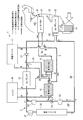
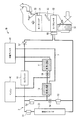
- FIG. 1 is a configuration diagram illustrating a vehicle air conditioner according to a first embodiment.
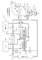
- FIG. 2 is a diagram for explaining an operation in the heating mode of the vehicle air conditioner according to the first embodiment.
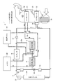
- FIG. 3 is a diagram for explaining the operation in the cooling mode of the vehicle air conditioner according to the first embodiment.
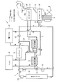
- FIG. 4 is a diagram for explaining the operation in the cooling / cooling mode of the vehicle air conditioner according to the first embodiment.
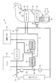
- FIG. 5 is a configuration diagram showing a vehicle air conditioner according to the second embodiment.
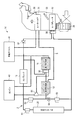
- FIG. 6 is a configuration diagram showing a vehicle air conditioner according to the third embodiment.
- FIG. 7 is a configuration diagram showing a vehicle air conditioner according to the fourth embodiment.
- FIG. 8 is a configuration diagram showing a vehicle air conditioner according to the fifth embodiment.
- the present disclosure is based on the configuration of a conventional vehicle air conditioner having an auxiliary heating function, and can easily heat or cool a temperature controlled component with a simple configuration at low cost. Providing the device.
- FIG. 1 is a configuration diagram illustrating the vehicle air conditioner according to the first embodiment of the present disclosure.
- the vehicle air conditioner 1 is provided in a vehicle including an engine (internal combustion engine) 40 corresponding to a heat generating component and an in-vehicle device (for example, an oil cooler or an inverter) 41 corresponding to a temperature control target component. It is a device that is installed and performs air conditioning in the passenger compartment.
- engine internal combustion engine
- in-vehicle device for example, an oil cooler or an inverter
- FIG. 2 is a diagram for explaining the operation in the heat pump heating mode for heating the passenger compartment.
- FIG. 3 is a diagram for explaining the operation in the cooling mode for cooling the passenger compartment.
- FIG. 4 is a diagram illustrating an operation in the cooling / cooling mode in which the vehicle interior is cooled and the in-vehicle device 41 is cooled. Details of the operations in FIGS. 2 to 4 will be described later.
- the vehicle air conditioner 1 includes a compressor 10, a first heat exchanger 11, a second heat exchanger 12, an outdoor condenser (corresponding to a condenser) 20, a heater core 31, an evaporator 32, a first on-off valve 51, and a second on-off valve. 52, a third on-off valve 53, a throttle valve 54, expansion valves 55 and 56, a check valve 57, and a three-way valve 58.
- a refrigerant circuit 2 (circuit shown by a solid line in FIG. 1) is configured by connecting at least two of these parts with a refrigerant pipe (passage) through which refrigerant flows, and between at least two of these parts.
- the coolant circuit 3 (the circuit shown by the dotted line in FIG. 1) is configured by connecting the coolant with a coolant pipe (passage) through which coolant flows.
- the vehicle air conditioner 1 is connected to the engine 40 and the vehicle-mounted device 41 via a coolant pipe.
- a refrigerant pipe that connects the compressor 10, the second heat exchanger 12, and the first heat exchanger 11 and circulates the refrigerant constitutes a heating refrigerant circuit 2 ⁇ / b> A.
- a refrigerant pipe connecting the condenser 20 and the evaporator 32 and circulating the refrigerant forms a cooling refrigerant circuit 2B.
- a part of the refrigerant circuit 2A for heating and a part of the refrigerant circuit 2B for cooling are common.
- the coolant piping that forms the coolant circuit 3 includes the engine 40 that is the object of cooling, the in-vehicle device 41 that is not only cooled but also the object of heating, and the first heat exchanger 11, the second heat exchanger 12, and The heater cores 31 are connected to each other and the coolant is circulated.
- the engine 40 includes an engine cooling unit.
- the engine cooling unit includes a water jacket for flowing the coolant around the engine 40 and a pump for flowing the coolant to the water jacket, and releases the exhaust heat of the engine 40 to the coolant flowing in the water jacket.
- the pump is rotated by the power of the engine 40, for example.
- the coolant inlet of the engine cooling section provided in the engine 40 communicates with the first heat exchanger 11 and the in-vehicle device 41 via the coolant pipe.
- the coolant outlet of the engine cooling unit included in the engine 40 communicates with the second heat exchanger 12 via the coolant pipe.
- the engine cooling unit may be provided with a radiator that releases heat to the outside air when the amount of exhaust heat from the engine 40 increases.
- the cooling liquid is an antifreezing liquid such as LLC (Long Life Coolant), and is a liquid for transporting heat.
- LLC Long Life Coolant
- the transfer of the coolant in the coolant circuit 3 can be performed using only the pump provided in the engine cooling unit. Thereby, reduction of the cost of an apparatus and reduction of the installation space of an apparatus can be aimed at.
- a pump may be added to another part of the coolant pipe.
- the in-vehicle device 41 is a temperature control target component that needs to be cooled as well as heated, such as an oil cooler or an inverter.
- the in-vehicle device 41 is also provided with, for example, a device temperature control unit having the same configuration as the engine cooling unit, and heat is released from the in-vehicle device 41 to the coolant flowing in the device temperature control unit included in the in-vehicle device 41. Heat is supplied from the liquid to the in-vehicle device 41.
- the inlet of the coolant of the device temperature adjustment unit included in the in-vehicle device 41 is communicated with the second heat exchanger 12 via the coolant pipe.
- the coolant outlet of the device temperature adjustment unit included in the in-vehicle device 41 communicates with the coolant inlet of the engine cooling unit included in the engine 40 via the coolant pipe.
- the coolant sent from the second heat exchanger 12 may be further introduced into the in-vehicle device 41 after passing through a radiator.
- the compressor 10 is a device that is driven by engine power or electricity, compresses sucked refrigerant, and discharges high-temperature and high-pressure refrigerant.
- the refrigerant compressed by the compressor 10 is sent from the discharge port of the compressor 10 to the outdoor condenser 20 or the second heat exchanger 12 through the refrigerant pipe.
- the low-temperature and low-pressure refrigerant discharged from the first heat exchanger 11 or the evaporator 32 is sucked from the suction port of the compressor 10 through the refrigerant pipe.
- the refrigerant pipe extending from the discharge port of the compressor 10 is provided with a branch portion that branches the refrigerant pipe into a pipe that reaches the refrigerant inlet of the outdoor capacitor 20 and a pipe that reaches the refrigerant inlet of the second heat exchanger 12. Yes.
- the refrigerant flows through the piping extending from the discharge port of the compressor 10 leading to this branching part both during heating and during cooling.
- a first on-off valve (corresponding to a switching unit) 51 that can block the flow of the refrigerant is disposed in a pipe between the branching unit and the refrigerant inlet of the outdoor capacitor 20.
- a second on-off valve (corresponding to a switching unit) 52 capable of blocking the flow of the refrigerant is disposed in the pipe between the branching unit and the refrigerant inlet of the second heat exchanger 12.
- the first on-off valve 51 and the second on-off valve 52 are, for example, valves that switch between opening and closing in the middle of the refrigerant pipe by electrical control.
- pilot valves that are a kind of electromagnetic valves are employed.
- the pilot type valve is a valve that controls a flow of fluid by opening and closing a small hole and operates a valve body by utilizing a pressure difference of the fluid generated thereby.
- the direction in which the refrigerant flows is always constant, so a pilot valve can be employed. In the case of a pilot valve, even if the refrigerant pressure in the refrigerant pipe to be arranged is high, it can be operated without any problem.
- the high-temperature and high-pressure refrigerant discharged from the compressor 10 is sent to the cooling refrigerant circuit 2B including the outdoor capacitor 20, or Whether to be sent to the refrigerant circuit 2A for heating including the second heat exchanger 12 is selected.
- the second heat exchanger 12 functions as a sub-condenser (condenser) in the heating mode, which will be described in detail later, and has an internal passage through which high-temperature and high-pressure refrigerant discharged from the compressor 10 flows and an internal passage through which coolant flows. Then, heat exchange is performed between the refrigerant and the coolant. Specifically, in the heating mode, the high-temperature and high-pressure refrigerant is sent from the compressor 10 to the second heat exchanger 12 to release heat from the high-temperature and high-pressure refrigerant to the coolant. Thereby, the 2nd heat exchanger 12 condenses a high temperature / high pressure refrigerant.
- the refrigerant inlet of the second heat exchanger 12 is communicated with the outlet of the compressor 10 via the refrigerant pipe of the heating refrigerant circuit 2A.
- the refrigerant outlet of the second heat exchanger 12 communicates with the intake port of the compressor 10 through the expansion valve 55 and the first heat exchanger 11 in order, similarly through the refrigerant pipe of the refrigerant circuit 2A for heating. Yes.
- the refrigerant inlet of the second heat exchanger 12 communicates with the refrigerant outlet of the outdoor condenser 20 via a pipe branched from the refrigerant pipe extending from the outdoor condenser 20.
- the refrigerant piping from the outdoor condenser 20 to the compressor 10 includes a refrigerant piping (first passage) that passes through the evaporator 32 on the way and a bypass refrigerant circuit that passes through the second heat exchanger 12 provided in parallel with the evaporator 32.
- the refrigerant piping of the bypass refrigerant circuit 2 ⁇ / b> B ′ upstream of the second heat exchanger 12 is connected to the refrigerant piping of the heating refrigerant circuit 2 ⁇ / b> A from the compressor 10 to the second heat exchanger 12.
- the refrigerant pipe of the bypass refrigerant 2 ⁇ / b> B ′ communicates with the refrigerant inlet of the second heat exchanger 12.
- a refrigerant pipe of the bypass refrigerant circuit 2B ′ is provided with a third on-off valve (corresponding to an on-off valve) 53 that allows the refrigerant to flow into the refrigerant inlet of the second heat exchanger 12 or blocks the refrigerant flow. It is done.
- the third on-off valve 53 is a valve that switches between opening and closing in the middle of the refrigerant pipe by, for example, electrical control, and shuts off the refrigerant flow when closed.
- a direct acting valve which is a kind of electromagnetic valve is employed as the third on-off valve 53.
- the direct acting valve is a valve that controls the flow of fluid (refrigerant) by operating a movable core and mechanically opening and closing a main orifice.
- a direct acting valve it is possible to open and close even if the pressure of the refrigerant is high by making the connection diameter to the refrigerant pipe small.
- the direct acting valve can fulfill the function of expanding the refrigerant, the throttle valve 54 described later can be dispensed with.
- a pilot valve can be used instead of the direct acting valve.
- the refrigerant sent from the outdoor capacitor 20 returns to the compressor 10 through only the refrigerant pipe having the evaporator 32 by switching control of the opening / closing of the third on-off valve 53.
- it is selected whether to return to the compressor 10 not only through the refrigerant pipe with the evaporator 32 but also through the refrigerant pipe of the bypass refrigerant circuit 2B ′ including the second heat exchanger 12 and the first heat exchanger 11.
- the third on-off valve 53 is not limited to the position shown in FIG. 1 as long as it can block the refrigerant flow at some point in the refrigerant piping of the bypass refrigerant circuit 2B ′.
- the second heat exchanger 12 functions as a sub-condenser (condenser) that condenses the refrigerant by exchanging heat between the high-temperature and high-pressure refrigerant and the coolant in a state where the refrigerant flows through the heating refrigerant circuit 2A. To do.
- the second heat exchanger 12 in the state where the refrigerant flows into the cooling refrigerant circuit 2B and the third on-off valve 53 is opened, the second heat exchanger 12 is supplied with the refrigerant and the coolant that are expanded after being sent from the outdoor capacitor 20. It functions as a sub-evaporator (evaporator) that exchanges heat between them to vaporize the refrigerant.
- a throttle valve 54 is disposed between the refrigerant inlet of the second heat exchanger 12 and the third on-off valve 53.
- the throttle valve 54 expands the high-temperature and high-pressure refrigerant, and sends the low-temperature and low-pressure refrigerant to the second heat exchanger 12.
- an orifice electromagnetic valve or the like may be used.
- the coolant inlet of the second heat exchanger 12 is communicated with the engine cooling part of the engine 40 via the coolant pipe.
- the coolant outlet of the second heat exchanger 12 communicates with either the heater core 31 or the in-vehicle device 41 through the coolant pipe by the three-way valve 58.
- the three-way valve 58 is configured such that, for example, the flow of the coolant sent from the refrigerant outlet of the second heat exchanger 12 is flowed toward the heater core 31 or toward the vehicle-mounted device 41 by electrical control. It is a valve to switch to.
- the first heat exchanger 11 functions as a sub-evaporator (evaporator) in the heating mode and the cooling / cooling mode.
- the first heat exchanger 11 has an internal passage through which a low-temperature and low-pressure refrigerant flows and an internal passage through which a cooling liquid flows, and performs heat exchange between the refrigerant and the cooling liquid.
- the low-temperature and low-pressure refrigerant is introduced from the expansion valve 55, and heat is transferred from the coolant to the low-temperature and low-pressure refrigerant. Moving. Thereby, the first heat exchanger 11 vaporizes the low-temperature and low-pressure refrigerant.
- the refrigerant inlet of the first heat exchanger 11 communicates with the refrigerant outlet of the second heat exchanger 12 via the expansion valve 55.
- the refrigerant outlet of the first heat exchanger 11 communicates with the refrigerant pipe connecting the check valve 57 and the compressor 10.
- the expansion valve 55 expands the refrigerant and discharges the low-temperature and low-pressure refrigerant to the first heat exchanger 11.
- the expansion valve 55 is disposed in the vicinity of the first heat exchanger 11 on the upstream side of the first heat exchanger 11.
- the expansion valve 55 is, for example, a thermal expansion valve that has a function of automatically adjusting the amount of refrigerant discharged according to the temperature of the refrigerant sent from the first heat exchanger 11.
- the coolant inlet of the first heat exchanger 11 is communicated with the heater core 31 via the coolant pipe.
- the coolant outlet of the first heat exchanger 11 communicates with the engine cooling section of the engine 40 via the coolant pipe.
- the outdoor condenser 20 has an internal passage through which high-temperature and high-pressure refrigerant flows and an internal passage through which air flows.
- the outdoor condenser 20 is disposed near the top of the vehicle in the engine room and exchanges heat between the refrigerant and the outside air.
- the high-temperature and high-pressure refrigerant discharged from the compressor 10 flows through the outdoor condenser 20 in the cooling mode and the cooling / cooling mode, and heat is discharged from the refrigerant to the outside air. Outside air is blown onto the outdoor capacitor 20 by, for example, a fan.
- a reservoir tank may be provided on the refrigerant delivery side of the outdoor capacitor 20.
- the heater core 31 and the evaporator 32 are disposed in an intake passage of an HVAC (Heating, Ventilation, and Air Conditioning) 30.
- the HVAC 30 is provided with a fan 34 for flowing intake air.
- the heater core 31 is included in the coolant circuit 3, and the evaporator 32 is included in the refrigerant circuit 2.
- the heater core 31 is a device that exchanges heat between the coolant and air, and is disposed in the intake passage of the HVAC 30 that supplies air into the passenger compartment. Heated coolant is supplied to the heater core 31 and releases heat to the intake air (air sent to the vehicle interior) sent into the vehicle compartment in the heating mode.
- the heater core 31 can adjust the amount of air passing through the opening of the door 33 in the intake passage.
- the door 33 can be opened and closed by electrical control, and is also called a mix door.
- the evaporator 32 is a device that exchanges heat between the low-temperature and low-pressure refrigerant and the air, and is disposed in the intake passage of the HVAC 30.
- the evaporator 32 is supplied with a low-temperature and low-pressure refrigerant in the cooling mode and the cooling / cooling mode, and cools the intake air (air sent to the vehicle interior) supplied to the vehicle interior.
- the expansion valve 56 expands the high-pressure refrigerant and discharges the low-temperature and low-pressure refrigerant to the evaporator 32.
- the expansion valve 56 is disposed in the vicinity of the evaporator 32 on the upstream side of the evaporator 32.
- the expansion valve 56 is, for example, a temperature type expansion valve having a function of automatically adjusting the amount of refrigerant to be discharged according to the temperature of the refrigerant sent from the evaporator 32.
- a check valve 57 is disposed in the middle of the refrigerant circuit from the evaporator 32 to the compressor 10.
- the check valve 57 is a valve that prevents the refrigerant from flowing back in the heating mode in which the refrigerant does not flow to the outdoor condenser 20 and the evaporator 32.
- the refrigerant pressure in the outdoor condenser 20 and the evaporator 32 may be low.
- the refrigerant flowing in the refrigerant circuit 2A of the first heat exchanger 11 and the second heat exchanger 12 flows back to the cooling refrigerant circuit 2B on the evaporator 32 side, and the heat pump cycle Efficiency will decrease.
- Such inconvenience can be avoided by the presence of the check valve 57.
- the vehicle air conditioner 1 has a control system configuration in which the compressor 10 is driven, the operating parts of the HVAC 30 are driven, and the on-off valves (first on-off valve 51, second on-off valve 52, and third on-off valve 53). And a control unit (not shown) for controlling the switching of the flow path of the three-way valve 58, the pump for transferring the cooling liquid by power, and the like.
- the control unit includes, for example, a microcomputer, an I / O, a program memory storing a control program, a working memory, and the like, and the microcomputer performs predetermined control according to the control program, but is configured as one unit. It may be made up of a plurality of units.
- the operation mode of the vehicle air conditioner 1 includes a hot water heating mode, a heat pump heating mode, a cooling mode, a cooling / cooling mode, and the like. These operating modes are switched to operate.
- the hot water heating mode is a mode in which the passenger compartment is heated without operating the heat pump.
- the heating mode, the cooling mode, and the cooling / cooling mode will be described in order as representative examples.
- FIG. 2 is a diagram for explaining the operation in the heating mode.
- the heating mode is a mode in which the first on-off valve 51 is closed, the second on-off valve 52 is opened, and the third on-off valve 53 is closed. Further, the door 33 of the heater core 31 is opened (for example, fully opened). Further, the three-way valve 58 is switched so that the coolant sent from the second heat exchanger 12 flows to the heater core 31.
- the refrigerant discharged from the compressor 10 passes through the second heat exchanger 12, the expansion valve 55, and the first heat exchanger 11 in order in the heating refrigerant circuit 2A and returns to the compressor 10. Circulate like so.
- the high-temperature and high-pressure refrigerant compressed by the compressor 10 dissipates heat to the coolant in the second heat exchanger 12 and condenses.
- the condensed refrigerant is expanded by the expansion valve 55 to become a low-temperature and low-pressure refrigerant, and is sent to the first heat exchanger 11.
- the low-temperature and low-pressure refrigerant is vaporized by absorbing heat from the coolant in the first heat exchanger 11.
- the vaporized low-pressure refrigerant is sucked into the compressor 10 and compressed again.
- the coolant circulates in the coolant circuit 3 so as to pass through the engine 40, the second heat exchanger 12, the heater core 31, and the first heat exchanger 11 in this order.
- the coolant that has absorbed the exhaust heat by the engine 40 is further heated by the second heat exchanger 12 and sent to the heater core 31.
- the coolant that has reached a high temperature can sufficiently heat the intake air that is sent into the passenger compartment by the heater core 31.
- the first heat exchanger 11 can release the heat to the refrigerant to vaporize the refrigerant. Further, the coolant cooled in the first heat exchanger 11 is sent to the engine 40 and used for cooling the engine 40.
- FIG. 3 is a diagram for explaining the operation in the cooling mode.
- the cooling mode is a mode in which the first on-off valve 51 is opened, the second on-off valve 52 is closed, and the third on-off valve 53 is also closed. Further, the door 33 of the heater core 31 is fully closed. Further, the three-way valve 58 is switched so that the coolant sent from the second heat exchanger 12 flows to the heater core 31.
- the refrigerant discharged from the compressor 10 circulates back through the outdoor condenser 20, the expansion valve 56, and the evaporator 32 in order in the cooling refrigerant circuit 2B so as to return to the compressor 10.
- the high-temperature and high-pressure refrigerant compressed by the compressor 10 dissipates heat to the air by the outdoor condenser 20 and condenses.
- the condensed refrigerant is expanded by the expansion valve 56 to become a low-temperature and low-pressure refrigerant and is sent to the evaporator 32.
- the low-temperature and low-pressure refrigerant cools and evaporates the intake air sent into the passenger compartment in the evaporator 32.
- the vaporized low-pressure refrigerant is sucked into the compressor 10 and compressed.
- the flow of the coolant is the same as in the heating mode, and circulates in the coolant circuit 3 so as to pass through the engine 40, the second heat exchanger 12, the heater core 31, and the first heat exchanger 11 in order. To do. In this case, when the coolant passes through the second heat exchanger 12, the heater core 31, and the first heat exchanger 11 in this order, it hardly exchanges heat with the refrigerant or air.
- the heat dissipation of the coolant is mainly performed by a radiator of an engine cooling unit in the engine 40.
- the engine 40 Since the engine 40 is very hot, it is cooled by heat dissipation from the radiator even if the outside air temperature is high. Here, it is good also as employ
- FIG. 4 is a diagram for explaining the operation in the cooling and cooling mode.
- the first on-off valve 51 is opened, the second on-off valve 52 is closed, and the third on-off valve 53 is opened. Further, the door 33 of the heater core 31 is fully closed. Further, the three-way valve 58 is switched so that the coolant sent from the second heat exchanger 12 flows not to the heater core 31 but to the in-vehicle device 41.
- the refrigerant discharged from the compressor 10 passes through the outdoor condenser 20 in the cooling refrigerant circuit 2B and then flows through the refrigerant pipe (first passage) passing through the evaporator 32, as well as the evaporator 32. And the refrigerant pipe (second passage) passing through each heat exchanger (the first heat exchanger 11 and the second heat exchanger 12) provided in parallel.
- the refrigerant sent from the outdoor condenser 20 passes through the expansion valve 56 and the evaporator 32 in order and returns to the compressor 10, the third on-off valve 53, the throttle valve 54, the second heat exchanger 12, and the first heat.
- the refrigerant flows through both the refrigerant pipes of the bypass refrigerant circuit 2B ′ that passes through the exchanger 11 and returns to the compressor 10 in order.
- the refrigerant compressed by the compressor 10 dissipates heat to the air by the outdoor condenser 20 and condenses.
- the condensed refrigerant expands in the expansion valve 56 to become a low-temperature and low-pressure refrigerant and is sent to the evaporator 32.
- the low-temperature and low-pressure refrigerant cools and evaporates the intake air sent into the passenger compartment in the evaporator 32.
- the vaporized low-pressure refrigerant is sucked into the compressor 10 and compressed.
- the refrigerant passing through the refrigerant pipe of the bypass refrigerant circuit 2 ⁇ / b> B ′ is expanded in the throttle valve 54 and then sent to the second heat exchanger 12.
- the second heat exchanger 12 cools the coolant by vaporizing the refrigerant, instead of condensing the refrigerant as in the heating mode.
- the refrigerant sent out from the second heat exchanger 12 expands in the expansion valve 55 to become a low-temperature and low-pressure refrigerant and is sent to the first heat exchanger 11.
- the low-temperature and low-pressure refrigerant is vaporized by absorbing heat from the coolant in the first heat exchanger 11.
- the vaporized low-pressure refrigerant is sucked into the compressor 10 and compressed again.
- the coolant circulates in the coolant circuit 3 so as to pass through the engine 40, the second heat exchanger 12, and the in-vehicle device 41 in order.
- the coolant that has absorbed the exhaust heat by the engine 40 is cooled by the second heat exchanger 12 and then sent to the in-vehicle device 41 via the three-way valve 58.
- the vehicle-mounted device 41 can be cooled by sending the coolant cooled by the second heat exchanger 12 to the vehicle-mounted device 41.
- Such an operation can sufficiently cool the passenger compartment and also cool the in-vehicle device 41.
- the vehicle air conditioner 1 uses the configuration of the hot water heater that uses the coolant of the engine 40 to flow through the heater core 31 for heating and the low-temperature and low-pressure refrigerant of the heat pump. It also has a heat pump type cooling device that performs cooling as a basic configuration. And it becomes the structure by which the auxiliary heating function which further heats a cooling fluid with a heat pump was added to this basic structure. With such a configuration, even when the engine 40 is at a low temperature, the vehicle interior can be quickly heated with a small amount of energy by the action of the heat pump.
- the basic structure is the same as that of a hot water heater and a heat pump type cooling device as used in a conventional vehicle, and at the time of cooling and heating.
- the common compressor 10 and the refrigerant By using the common compressor 10 and the refrigerant, the heating performance can be improved at a low cost, and the increase in installation space can be reduced from the conventional configuration.
- the bypass refrigerant circuit 2B ′ is added to the cooling refrigerant circuit 2B, the third on-off valve is also arranged, and the refrigerant flows through the bypass refrigerant circuit 2B ′.
- the second heat exchanger 12 is made to function as a sub-evaporator, not as a sub-capacitor. Accordingly, it is possible to add a function of cooling the in-vehicle device 41 while keeping the basic configuration as it is while suppressing an increase in the number of parts and installation space as much as possible.
- cooling refrigerant circuit 2B it is possible to not only heat the cooling liquid but also to cool it by only changing a part of the refrigerant flow path. It can be performed.
- the refrigerant pipe extending from the second heat exchanger 12 to the first heat exchanger 11 and the refrigerant extending from the outdoor condenser 20 to the evaporator 32. Since the pipes are different, each refrigerant pipe can be independently adjusted to suit a plurality of operation modes (for example, a heating mode and a cooling mode).
- the expansion valve 55 that expands the refrigerant in front of the first heat exchanger 11 and the expansion valve 56 that expands the refrigerant in front of the evaporator 32 are provided.
- each expansion valve can be independently adjusted to suit a plurality of operating modes.
- the adjustment can be made according to a plurality of operation modes. It becomes possible to demonstrate specialized operation performance. In addition, the operation mode can be switched smoothly.
- the outdoor condenser is switched when the operation mode is switched.
- the refrigerant accumulates in 20 and it becomes difficult to collect and the amount of refrigerant becomes unstable.
- the vehicle air conditioner 1 of the present embodiment such a problem hardly occurs.
- the configuration in which the first heat exchanger 11 is provided on the downstream side of the second heat exchanger 12 in the refrigerant circuit 2A for heating has been described as an example.
- the structure which does not provide the heat exchanger 11 may be sufficient. Next, such a case will be described.
- FIG. 5 is a configuration diagram illustrating a vehicle air conditioner 1a according to the second embodiment of the present disclosure.
- symbol is attached
- This vehicle air conditioner 1a has the same basic configuration as that of the first embodiment. However, in this vehicle air conditioner 1a, the first heat exchanger 11 is not disposed between the refrigerant outlet of the second heat exchanger 12 and the refrigerant inlet of the compressor 10 in the refrigerant circuit 2, A hot gas cycle method may be employed.
- the coolant circuit 3 is configured so that the coolant circulates between the engine 40, the second heat exchanger 12, and the in-vehicle device 41.
- the vehicle air conditioner 1a as well, as with the vehicle air conditioner 1, it is possible not only to heat the coolant by the second heat exchanger 12, but also to cool it.
- the operation mode can be switched to any one of the heating mode, the cooling mode, and the cooling / cooling mode in accordance with the temperature control status (desired to warm / cool) of the in-vehicle device 41.
- the operation mode is switched to the heating mode.
- the refrigerant discharged from the compressor 10 circulates back to the compressor 10 through the second heat exchanger 12.
- the coolant circulates through the engine 40, the second heat exchanger 12, and the in-vehicle device 41 in order.
- heat exchange is performed between the high-temperature and high-pressure refrigerant and the coolant, and the heated coolant is sent to the in-vehicle device 41 to heat the in-vehicle device 41.
- the operation mode is switched to the cooling mode.
- the refrigerant discharged from the compressor 10 circulates back to the compressor 10 through the outdoor condenser 20, the expansion valve 56, the evaporator 32, and the compressor 10 in this order.
- the coolant flow is the same as in the heating mode.
- the operation mode is switched to the cooling / cooling mode.
- the refrigerant discharged from the compressor 10 not only flows through the refrigerant pipe (first passage) passing through the evaporator 32 as in the cooling mode, but also includes second heat provided in parallel with the evaporator 32. It flows through the refrigerant pipe (second passage) passing through the exchanger 12. The flow of the coolant is the same as in the heating mode and the cooling mode.
- heat exchange is performed between the refrigerant expanded in the throttle valve 54 and the coolant, and the cooled coolant is sent to the in-vehicle device 41 to cool the in-vehicle device 41.
- piping for sending the coolant sent from the second heat exchanger 12 to the heater core 31 is omitted, but the vehicle-mounted device 41 or the heater core 31 is the same as in the first embodiment.
- the coolant circuit 3 may be configured so that the coolant can be delivered to any one of the above.
- FIG. 6 is a configuration diagram illustrating a vehicle air conditioner according to the third embodiment of the present disclosure.
- symbol is attached
- the vehicle air conditioner 1b has a configuration in which a throttle valve 59 and the first heat exchanger 11 are added to the vehicle air conditioner 1a of the second embodiment. That is, the throttle valve 59 and the first heat exchanger 11 similar to the first embodiment are provided between the refrigerant outlet of the second heat exchanger 12 and the refrigerant inlet of the compressor 10 in the refrigerant circuit 2. Arranged to constitute a heat pump cycle.
- the coolant circuit 3 is configured such that the coolant circulates between the engine 40, the second heat exchanger 12, the in-vehicle device 41, and the first heat exchanger 11.
- the vehicle air conditioner 1b it is possible not only to heat the coolant by the second heat exchanger 12 but also to cool the vehicle as in the case of the vehicle air conditioner 1a.
- the on / off control of each on-off valve controls the heating mode and the cooling mode.
- the operation mode can be switched to either the cooling / cooling mode.
- the exhaust heat of the engine 40 can be absorbed more and stable driving can be performed without depending on the outside air temperature or the like.
- a throttle valve 59 for expanding the refrigerant is disposed upstream of the first heat exchanger 11.
- the throttle valve 59 has the same configuration as that of the throttle valve 54, but the above-described expansion valve 55 may be employed instead of the throttle valve 54, and the selection of a specific valve type may be changed as appropriate.
- the piping for sending the coolant sent from the second heat exchanger 12 to the heater core 31 is omitted, but the vehicle-mounted device 41 or the heater core 31 is the same as in the first embodiment.
- the coolant circuit 3 may be configured so that the coolant can be delivered to any one of the above.
- FIG. 7 is a configuration diagram illustrating a vehicle air conditioner 1c according to the fourth embodiment of the present disclosure. Note that the same reference numerals are given to the same components as those in the first to third embodiments, and a duplicate description will be omitted.
- the vehicle air conditioner 1c has the same basic configuration as that of the first embodiment, and the refrigerant circuit 2 is configured in the same manner as in the first embodiment. However, the coolant circuit 3 is partially different in the route of the coolant pipe.
- the coolant circuit 3 is configured so that the coolant circulates between the engine 40, the second heat exchanger 12, the heater core 31, the in-vehicle device 41, and the first heat exchanger 11. Yes.
- the heater core 31 and the in-vehicle device 41 are arranged in series. Therefore, when heating the heater core 31, the vehicle-mounted device 41 can also be heated simultaneously, and when heating the vehicle-mounted device 41, the heater core 31 can also be heated simultaneously.
- FIG. 8 is a configuration diagram illustrating a vehicle air conditioner 1d according to the fifth embodiment of the present disclosure.
- the same components as those in the first to fourth embodiments are denoted by the same reference numerals, and redundant description is omitted.
- This vehicle air conditioner 1d has the same basic configuration as that of the third embodiment, and the refrigerant circuit 2 is configured in the same manner as in the first and third embodiments. However, the coolant circuit 3 is partially different in the route of the coolant pipe.
- the coolant pipe from the coolant delivery port of the engine 40 is branched by a three-way valve 61, and the coolant fluid introduction of the engine 40 is introduced through the second heat exchanger 12 and the in-vehicle device 41 in order.
- the coolant flow path can be switched between the coolant flow path that returns to the opening and the coolant flow path that passes through the expansion valve 55 and the first heat exchanger 11 and returns to the refrigerant liquid inlet of the engine 40. It is configured as follows.
- the three-way valve 61 is a valve that can switch the flow of the coolant sent from the engine 40 between one side and the other side, for example, by electrical control. In this way, by flowing the coolant through one of the first heat exchanger 11 and the second heat exchanger 12, the pressure loss can be reduced.
- the vehicle air conditioner of the present disclosure is applied not only to a system that configures a heat pump cycle, but also to a system that configures a hot gas cycle, such as the vehicle air conditioner 1a of the second embodiment. May be.
- the heating component of the vehicle is the engine 40
- other heating components such as an electric motor for driving in an electric vehicle, a secondary battery for supplying electric power for driving It may be.
- first heat exchanger 11, the second heat exchanger 12, the expansion valve 55, the first on-off valve 51, the second on-off valve 52, and the like may be configured as an integrated unit.
- the unit may be one in which each component is housed and integrated in one housing, or may be one in which each component is joined.
- the present disclosure can be used for an air conditioner for vehicles mounted on various vehicles such as an engine vehicle, an electric vehicle, or a HEV (Hybrid Electric Vehicle) vehicle.
- vehicles such as an engine vehicle, an electric vehicle, or a HEV (Hybrid Electric Vehicle) vehicle.
- HEV Hybrid Electric Vehicle
- Coolant circuit 10 Compressor 11 First heat exchanger 12 Second heat exchange 51 First on-off valve (switching part) 52 Second on-off valve (switching part) 53 Third open / close valve 54, 59 Throttle valve 55, 56 Expansion valve 57 Check valve 58, 61 Three-way valve 20 Outdoor condenser 30 HVAC 31 Heater core 32 Evaporator 33 Door 34 Fan 40 Engine (engine cooling part) 41 On-vehicle device (engine temperature control part)
Abstract
車両用空調装置は、コンプレッサと、熱交換器と、コンデンサと、エバポレータと、冷媒通路と、開閉弁と、を備える。コンプレッサは、冷媒を圧縮する。熱交換器は、冷媒と熱輸送用の冷却液との間で熱交換を行う。コンデンサは、高温高圧の冷媒の熱を放出させることにより、冷媒を凝縮させる。エバポレータは、低温低圧の冷媒と車室内へ送られる空気との間で熱交換を行う。冷媒通路には、冷媒が流れる。開閉弁は、冷媒通路を遮断可能とする。暖房用冷媒回路は、冷媒が、コンプレッサから熱交換器を通ってコンプレッサに戻るように構成される。冷房用冷媒回路は、冷媒が、コンプレッサからコンデンサ及びエバポレータを通ってコンプレッサに戻るように構成される。冷房用冷媒回路のうちコンデンサからコンプレッサへ至る冷媒通路は、冷媒通路の途中で、エバポレータを通る第1通路と、エバポレータと並列に設けられた熱交換器を通る第2通路とに分かれている。開閉弁は、第2通路における熱交換器の上流側に設けられる。
Description
本開示は、車両用空調装置に関する。
従来の車両用の暖房装置として、エンジン冷却水の熱を利用して車室内を暖房する温水式ヒータが多く採用されている。また、従来の車両用の冷房装置として、車室内へ送られる空気をヒートポンプの低温冷媒により冷却するヒートポンプ式冷房装置が一般に採用されている。
特許文献1には、従来の車両に採用されているような温水式ヒータ、並びに、ヒートポンプ式冷房装置の構成を基本としつつ、冷房時と暖房時とで共通のコンプレッサおよび冷媒を利用し、ヒートポンプによりエンジン冷却水をさらに加熱する補助暖房機能を付加することで、暖房性能を向上させた車両用空調装置が開示されている。
また、車両に搭載された各種部品には、通常冷却水による冷却のみを必要とするエンジン等の発熱部品の他、オイルクーラやインバータ等の車載デバイスのように、冷却や加温が必要な調温対象部品も知られている。
本開示の一態様に係る車両用空調装置は、コンプレッサと、熱交換器と、コンデンサと、エバポレータと、冷媒通路と、開閉弁と、を備える。コンプレッサは、冷媒を圧縮する。熱交換器は、冷媒と熱輸送用の冷却液との間で熱交換を行う。コンデンサは、高温高圧の冷媒の熱を放出させることにより、冷媒を凝縮させる。エバポレータは、低温低圧の冷媒と車室内へ送られる空気との間で熱交換を行う。冷媒通路には、冷媒が流れる。開閉弁は、冷媒通路を遮断可能とする。暖房用冷媒回路は、冷媒が、コンプレッサから熱交換器を通ってコンプレッサに戻るように構成される。冷房用冷媒回路は、冷媒が、コンプレッサからコンデンサ及びエバポレータを通ってコンプレッサに戻るように構成される。冷房用冷媒回路のうちコンデンサからコンプレッサへ至る冷媒通路は、冷媒通路の途中で、エバポレータを通る第1通路と、エバポレータと並列に設けられた熱交換器を通る第2通路とに分かれている。開閉弁は、第2通路における熱交換器の上流側に設けられる。
本開示によれば、従来の補助暖房機能を備えた車両用空調装置の構成を基本としつつ、簡易な構成により低コストで、調温対象部品の加熱ないし冷却を容易に行うことができる。
本開示の実施の形態の説明に先立ち、従来の車両用空調装置における問題点を簡単に説明する。特許文献1に開示の車両用空調装置では、エンジン冷却は行われていたが、調温対象部品の冷却ないし加温については触れられていない。近年、特許文献1に開示の車両用空調装置の構成を基本としつつ、調温対象部品の冷却ないし加温を行うような調温機能を簡易な構成により低コストで実現可能な車両用空調装置の開発が強く望まれている。
本開示は、従来の補助暖房機能を備えた車両用空調装置の構成を基本としつつ、簡易な構成により低コストで、調温対象部品の加熱ないし冷却を容易に行うことが可能な車両用空調装置を提供する。
以下、本開示の各実施の形態について図面を参照して詳細に説明する。
[第1の実施の形態]
図1は、本開示の第1の実施の形態の車両用空調装置を示す構成図である。
図1は、本開示の第1の実施の形態の車両用空調装置を示す構成図である。
第1の実施の形態の車両用空調装置1は、発熱部品に相当するエンジン(内燃機関)40、調温対象部品に相当する車載デバイス(例えば、オイルクーラやインバータ等)41を備えた車両に搭載されて、車室内の空気調整を行う装置である。
図2は、車室内を暖房するヒートポンプ式の暖房モードにおける動作を説明する図である。図3は、車室内を冷房する冷房モードにおける動作を説明する図である。図4は、車室内を冷房し、且つ、車載デバイス41を冷却する冷房兼冷却モードにおける動作を説明する図である。図2~図4における動作の詳細は後述する。
車両用空調装置1は、コンプレッサ10、第1熱交換器11、第2熱交換器12、室外コンデンサ(コンデンサに相当)20、ヒーターコア31、エバポレータ32、第1開閉弁51,第2開閉弁52,第3開閉弁53、絞り弁54、膨張弁55,56、逆止弁57、三方弁58と、を具備する。これらの部品の少なくとも2つの間を、冷媒を流す冷媒配管(通路)で繋ぐことにより冷媒回路2(図1の実線で示される回路)が構成され、および、これらの部品の少なくとも2つの間を、冷却液を流す冷却液配管(通路)で繋ぐことにより冷却液回路3(図1の点線で示される回路)が構成される。また、車両用空調装置1は、エンジン40および車載デバイス41と、冷却液配管を介して繋がっている。
冷媒回路2のうち、コンプレッサ10、第2熱交換器12、第1熱交換器11の間を結び、冷媒が循環する冷媒配管は、暖房用の冷媒回路2Aをなし、また、コンプレッサ10、室外コンデンサ20、エバポレータ32の間を結び、冷媒が循環する冷媒配管は、冷房用の冷媒回路2Bをなしている。なお、暖房用の冷媒回路2Aの一部と、冷房用の冷媒回路2Bの一部とは共通している。
冷却液回路3をなす冷却液配管は、冷却の対象であるエンジン40、冷却のみならず加温の対象ともなる車載デバイス41、それに、第1熱交換器11、第2熱交換器12、および、ヒーターコア31の間を結び、冷却液が循環するように構成されている。
エンジン40は、エンジン冷却部を備えている。エンジン冷却部は、エンジン40の周囲に冷却液を流すウォータジャケットと、ウォータジャケットに冷却液を流すポンプとを具備し、ウォータジャケットに流れる冷却液にエンジン40の排熱を放出させる。ポンプは、例えば、エンジン40の動力により回転する。
エンジン40が備えるエンジン冷却部の冷却液の導入口は、冷却液配管を介して第1熱交換器11、および、車載デバイス41に連通している。また、エンジン40が備えるエンジン冷却部の冷却液の送出口は、冷却液配管を介して第2熱交換器12に連通している。なお、エンジン冷却部には、エンジン40の排熱量が多くなった場合に、熱を外気に放出するラジエータが備わっていてもよい。
冷却液は、例えば、LLC(Long Life Coolant)等の不凍液であり、熱を輸送するための液体である。ここで、冷却液回路3における冷却液の移送は、エンジン冷却部が備えたポンプのみを用いておこなうことができる。これにより、装置のコストの低減および装置の設置スペースの縮小を図ることができる。なお、冷却液の移送能力を高めるために、冷却液配管の他の箇所にポンプを追加してもよい。
車載デバイス41は、例えば、オイルクーラやインバータ等のように、加温のみならず冷却する必要がある調温対象部品である。車載デバイス41にも、例えば、エンジン冷却部と同様な構成のデバイス調温部を設けて、車載デバイス41が備えるデバイス調温部に流れる冷却液に車載デバイス41から熱を放出させ、また、冷却液から車載デバイス41に熱を供給する。ここで、デバイス調温部にも、冷却液を動力で移送するポンプを追加してもよい。
車載デバイス41が備えるデバイス調温部の冷却液の導入口は、冷却液配管を介して第2熱交換器12に連通されている。一方、車載デバイス41が備えるデバイス調温部の冷却液の送出口は、冷却液配管を介して、エンジン40が備えるエンジン冷却部の冷却液の導入口に連通している。なお、車載デバイス41の排熱量が多いような場合には、第2熱交換器12から送出された冷却液を、さらにラジエータに通してから車載デバイス41に導入させてもよい。
コンプレッサ10は、エンジンの動力または電気により駆動して、吸入した冷媒を圧縮し、高温高圧の冷媒を吐出する装置である。コンプレッサ10で圧縮された冷媒は、コンプレッサ10の吐出口より冷媒配管を通って室外コンデンサ20、または、第2熱交換器12へ送られる。
また、第1熱交換器11、または、エバポレータ32から吐出される低温低圧の冷媒は、冷媒配管を通ってコンプレッサ10の吸入口から吸入される。
コンプレッサ10の吐出口から延びる冷媒配管には、室外コンデンサ20の冷媒導入口に至る配管と、第2熱交換器12の冷媒導入口に至る配管とに冷媒配管を分岐させる分岐部が設けられている。
この分岐部に至るコンプレッサ10の吐出口から延びる配管には、暖房時にも、冷房時にも冷媒が流れる。そして、上記分岐部と室外コンデンサ20の冷媒導入口との間の配管には、冷媒の流れを遮断可能な第1開閉弁(切替部に相当)51が配置されている。一方、上記分岐部と第2熱交換器12の冷媒導入口との間の配管には、冷媒の流れを遮断可能な第2開閉弁(切替部に相当)52が配置されている。
第1開閉弁51および第2開閉弁52は、例えば、電気的な制御により冷媒配管の途中で開閉を切り替える弁である。例えば、第1開閉弁51および第2開閉弁52として、電磁弁の一種であるパイロット式弁が採用される。パイロット式弁は、小孔を開閉させることで流体の流れを制御し、それによって生じる流体の圧力差を利用して弁体を作動させる弁である。第1開閉弁51、第2開閉弁52を配置する冷媒配管の箇所では、冷媒が流れる方向は常に一定であるため、パイロット式弁を採用することができる。パイロット式弁の場合、配置する冷媒配管における冷媒の圧力が高くても問題なく作動させることができる。
そして、第1開閉弁51および第2開閉弁52の開閉の切り替え制御により、コンプレッサ10から吐出された高温高圧の冷媒が、室外コンデンサ20を含む冷房用の冷媒回路2Bに送出されるのか、または、第2熱交換器12を含む暖房用の冷媒回路2Aに送出されるのかが選択される。
第2熱交換器12は、後に詳しく説明する暖房モードではサブコンデンサ(凝縮器)として機能し、コンプレッサ10から吐出された高温高圧の冷媒を流す内部通路と、冷却液を流す内部通路とを有し、冷媒と冷却液との間で熱交換を行う。具体的には、第2熱交換器12には、暖房モードのときに、コンプレッサ10から高温高圧の冷媒が送られて、高温高圧の冷媒から冷却液へ熱を放出させる。これにより、第2熱交換器12は、高温高圧の冷媒を凝縮させる。
第2熱交換器12の冷媒導入口は、暖房用の冷媒回路2Aの冷媒配管を介してコンプレッサ10の吐出口に連通されている。一方、第2熱交換器12の冷媒送出口は、同じく暖房用の冷媒回路2Aの冷媒配管を介して、膨張弁55および第1熱交換器11を順に経てコンプレッサ10の吸入口に連通している。さらに、第2熱交換器12の冷媒導入口は、室外コンデンサ20から延びる冷媒配管から分岐する配管を介して、室外コンデンサ20の冷媒送出口にも連通している。
このように、室外コンデンサ20からコンプレッサ10へ至る冷媒配管は、途中でエバポレータ32を通る冷媒配管(第1通路)と、エバポレータ32と並列に設けられた第2熱交換器12を通るバイパス冷媒回路2B’の冷媒配管(第2通路)とに分岐している。第2熱交換器12の上流側のバイパス冷媒回路2B’の冷媒配管は、コンプレッサ10から第2熱交換器12に至る暖房用の冷媒回路2Aの冷媒配管に接続される。これにより、バイパス冷媒2B’の冷媒配管は、第2熱交換器12の冷媒導入口に連通する。
また、バイパス冷媒回路2B’の冷媒配管のうち、第2熱交換器12の冷媒送出口から膨張弁55および第1熱交換器11を順に経て、コンプレッサ10の吸入口に連通される部分は、暖房用の冷媒回路2Aの冷媒配管と共通のものとなっている。そして、バイパス冷媒回路2B’の冷媒配管には、第2熱交換器12の冷媒導入口に冷媒を流入させ、または、冷媒の流れを遮断する第3開閉弁(開閉弁に相当)53が設けられる。
第3開閉弁53は、例えば、電気的な制御により、冷媒配管の途中で開閉を切り替える弁であり、閉じたときに冷媒の流れを遮断する。例えば、第3開閉弁53として、電磁弁の一種である直動式弁が採用される。直動式弁は、可動コアを作動させて機械的にメインオリフィスを開閉させることにより、流体(冷媒)の流れを制御する弁である。
直動式弁の場合、冷媒配管に対する接続口径を小口径にすることで、冷媒の圧力が高くても開閉させることができる。この場合、直動式弁は冷媒を膨張させる機能を果たすことができるので、後述する絞り弁54を不要とすることもできる。また、第3開閉弁53を逆止弁と併用することで、直動式弁の代わりにパイロット式弁を用いることもできる。
冷房用の冷媒回路2Bに冷媒が流れる状態では、第3開閉弁53の開閉の切り替え制御により、室外コンデンサ20から送出された冷媒が、エバポレータ32のある冷媒配管だけを通ってコンプレッサ10に戻るか、または、エバポレータ32のある冷媒配管だけでなく、第2熱交換器12および第1熱交換器11を含むパイパス冷媒回路2B’の冷媒配管も通ってコンプレッサ10に戻るのかが選択される。なお、第3開閉弁53は、バイパス冷媒回路2B’の冷媒配管のどこかで冷媒の流れを遮断できればよく、その位置は図1に示した位置に限定されることはない。
また、第2熱交換器12は、暖房用の冷媒回路2Aに冷媒が流れる状態では、高温高圧の冷媒と冷却液との間で熱交換させて冷媒を凝縮させるサブコンデンサ(凝縮器)として機能する。一方、冷房用の冷媒回路2Bに冷媒が流れ、かつ、第3開閉弁53が開いた状態では、第2熱交換器12は、室外コンデンサ20から送出された後に膨張させた冷媒と冷却液との間で熱交換させて冷媒を気化させるサブエバポレータ(蒸発器)として機能する。
さらに、第2熱交換器12の冷媒導入口と第3開閉弁53との間には、絞り弁54が配置される。絞り弁54は、高温高圧の冷媒を膨張させ、低温低圧の冷媒を第2熱交換器12へ送出する。なお、第3開閉弁53と絞り弁54の代わりにオリフィス電磁弁などを用いることとしてもよい。
一方、冷却液回路3においては、第2熱交換器12の冷却液の導入口は、冷却液配管を介してエンジン40のエンジン冷却部に連通されている。一方、第2熱交換器12の冷却液の送出口は、冷却液配管を介して三方弁58により、ヒーターコア31または車載デバイス41のいずれかに連通する。
三方弁58は、例えば、電気的な制御により、第2熱交換器12の冷媒送出口から送出された冷却液の流れを、ヒーターコア31に向かう流れと、車載デバイス41に向かう流れのいずれかに切り替える弁である。
第1熱交換器11は、暖房モード、および、冷房兼冷却モードにおいてサブエバポレータ(蒸発器)として機能する。この第1熱交換器11は、低温低圧の冷媒を流す内部通路と、冷却液を流す内部通路とを有し、冷媒と冷却液との間で熱交換を行う。第1熱交換器11では、後に詳しく説明するが、暖房モード、および、冷房兼冷却モードのときに、膨張弁55から低温低圧の冷媒が導入され、冷却液から低温低圧の冷媒へと熱が移動する。これにより、第1熱交換器11は低温低圧の冷媒を気化させる。
第1熱交換器11の冷媒導入口は、膨張弁55を介して、第2熱交換器12の冷媒送出口に連通している。一方、第1熱交換器11の冷媒送出口は、逆止弁57とコンプレッサ10とを接続する冷媒配管の途中に連通している。
膨張弁55は、冷媒を膨張させ、低温低圧となった冷媒を第1熱交換器11に吐出する。膨張弁55は、第1熱交換器11の上流側に第1熱交換器11に近接して配置されている。膨張弁55は、例えば、第1熱交換器11から送出される冷媒の温度により、吐出する冷媒量を自動的に調整する機能を有する温度式膨張弁(Thermal Expansion Valve)である。
また、冷却液回路3においては、第1熱交換器11の冷却液の導入口は、冷却液配管を介してヒーターコア31に連通される。一方、第1熱交換器11の冷却液の送出口は、冷却液配管を介してエンジン40のエンジン冷却部に連通している。
室外コンデンサ20は、高温高圧の冷媒を流す内部通路と、空気を流す内部通路とを有し、例えばエンジンルーム内の車両の先頭付近に配置されて、冷媒と外気との間で熱交換を行う。室外コンデンサ20には、冷房モード、および、冷房兼冷却モードのときに、コンプレッサ10から吐出された高温高圧の冷媒が流れ、冷媒から外気へ熱が排出される。室外コンデンサ20には、例えば、ファンにより外気が吹き付けられる。なお、室外コンデンサ20の冷媒の送出側に、リザーバタンクを設けることとしてもよい。
ヒーターコア31とエバポレータ32は、HVAC(Heating, Ventilation, and Air Conditioning)30の吸気通路内に配置される。HVAC30には、吸気を流すファン34が設けられている。ヒーターコア31は、冷却液回路3に含まれており、エバポレータ32は、冷媒回路2に含まれている。
ヒーターコア31は、冷却液と空気との間で熱交換を行う機器であり、車室内へ空気を供給するHVAC30の吸気通路内に配置される。ヒーターコア31には、加熱された冷却液が供給され、暖房モードのとき、車室内へ送られる吸気(車室内に送られる空気)に熱を放出する。ヒーターコア31は、吸気通路内にあるドア33の開度により通過する空気の量を調整可能になっている。ここでドア33は、電気的な制御で開閉可能であり、ミックスドアとも呼ばれる。
エバポレータ32は、低温低圧の冷媒と、空気との間で熱交換を行う機器であり、HVAC30の吸気通路内に配置される。エバポレータ32には、冷房モード、冷房兼冷却モードのとき、低温低圧の冷媒が流され、車室内へ供給される吸気(車室内に送られる空気)を冷却する。
膨張弁56は、高圧の冷媒を膨張させ、低温低圧の冷媒をエバポレータ32に吐出する。膨張弁56は、エバポレータ32の上流側にエバポレータ32に近接して配置されている。膨張弁56は、例えば、エバポレータ32から送出される冷媒の温度により、吐出する冷媒量を自動的に調整する機能を有する温度式膨張弁である。
エバポレータ32からコンプレッサ10へ至る冷媒回路の途中には、逆止弁57が配置されている。逆止弁57は、室外コンデンサ20およびエバポレータ32に冷媒が流れない暖房モードのときに、冷媒の逆流を防ぐ弁である。
暖房モードにおいても、外気が低いと、室外コンデンサ20およびエバポレータ32における冷媒圧力が低くなることがある。この圧力低下があると、第1熱交換器11および第2熱交換器12の冷媒回路2Aに流れている冷媒が、エバポレータ32側の冷房用の冷媒回路2Bへ逆流してしまい、ヒートポンプサイクルの効率が低下してしまう。このような不都合を逆止弁57があることにより回避することができる。
また、車両用空調装置1は、制御系の構成として、コンプレッサ10の駆動、HVAC30の各動作部分の駆動、各開閉弁(第1開閉弁51,第2開閉弁52,第3開閉弁53)の開閉、三方弁58の流路の切替、冷却液を動力で移送するポンプ等をそれぞれ制御するための制御部(図示せず)を備えている。制御部は、例えば、マイクロコンピュータ、I/O、制御プログラムを格納したプログラムメモリ、作業用のメモリ等を備え、マイクロコンピュータが制御プログラムに従って所定の制御を行う装置であるが、一つのユニットとして構成されていてもよいし、複数のユニットから構成されていてもよい。
次に、車両用空調装置1の動作について説明する。車両用空調装置1の動作モードには、温水式の暖房モードの他、ヒートポンプ式の暖房モード、冷房モード、冷房兼冷却モード等があり、これらの動作モードを切り替えて動作する。このうち温水式の暖房モードとは、ヒートポンプを作動させずに車室内を暖房するモードである。以下では、暖房モード、冷房モード、および、冷房兼冷却モードを代表例として順に説明する。
[暖房モード]
図2は、暖房モードにおける動作を説明する図である。暖房モードは、第1開閉弁51が閉じ、第2開閉弁52が開き、第3開閉弁53が閉じた状態となるモードである。また、ヒーターコア31のドア33は開かれる(例えば全開)。さらに、三方弁58は、第2熱交換器12から送出された冷却液が、ヒーターコア31に流れるように切り替えられる。
図2は、暖房モードにおける動作を説明する図である。暖房モードは、第1開閉弁51が閉じ、第2開閉弁52が開き、第3開閉弁53が閉じた状態となるモードである。また、ヒーターコア31のドア33は開かれる(例えば全開)。さらに、三方弁58は、第2熱交換器12から送出された冷却液が、ヒーターコア31に流れるように切り替えられる。
暖房モードでは、コンプレッサ10から吐出された冷媒は、暖房用の冷媒回路2Aにて、第2熱交換器12、膨張弁55、および、第1熱交換器11を順に通って、コンプレッサ10に戻るように循環する。
ここで、コンプレッサ10により圧縮された高温高圧の冷媒は、第2熱交換器12にて冷却液へ放熱して凝縮する。凝縮した冷媒は、膨張弁55により膨張して低温低圧の冷媒となり、第1熱交換器11へ送られる。低温低圧の冷媒は、第1熱交換器11にて冷却液から熱を吸収して気化する。気化した低圧の冷媒は、コンプレッサ10に吸引されて再び圧縮される。
冷却液は、冷却液回路3にて、エンジン40、第2熱交換器12、ヒーターコア31、および、第1熱交換器11を順に通るように循環する。ここで、エンジン40にて排熱を吸収した冷却液は、さらに第2熱交換器12で加熱されてヒーターコア31に送られる。高温になった冷却液は、ヒーターコア31で車室内へ送られる吸気を十分に加熱することができる。
そして、ヒーターコア31を通過した冷却液は、外気より温度が高い状態であるため、第1熱交換器11にて冷媒に熱を放出して冷媒を気化させることができる。また、第1熱交換器11にて冷却された冷却液はエンジン40に送られ、エンジン40の冷却に用いられる。
このような動作により、車室内の十分な暖房を行うことができる。
[冷房モード]
図3は、冷房モードの動作を説明する図である。冷房モードは、第1開閉弁51が開き、第2開閉弁52が閉じ、第3開閉弁53も閉じた状態となるモードである。また、ヒーターコア31のドア33は全閉される。さらに、三方弁58は、第2熱交換器12から送出された冷却液が、ヒーターコア31に流れるように切り替えられる。
図3は、冷房モードの動作を説明する図である。冷房モードは、第1開閉弁51が開き、第2開閉弁52が閉じ、第3開閉弁53も閉じた状態となるモードである。また、ヒーターコア31のドア33は全閉される。さらに、三方弁58は、第2熱交換器12から送出された冷却液が、ヒーターコア31に流れるように切り替えられる。
冷房モードでは、コンプレッサ10から吐出された冷媒は、冷房用の冷媒回路2Bにて、室外コンデンサ20、膨張弁56、および、エバポレータ32を順に通って、コンプレッサ10に戻るように循環する。
ここで、コンプレッサ10により圧縮された高温高圧の冷媒は、室外コンデンサ20にて空気へ放熱して凝縮する。凝縮した冷媒は、膨張弁56により膨張して低温低圧の冷媒となり、エバポレータ32へ送られる。低温低圧の冷媒は、エバポレータ32にて、車室内へ送られる吸気を冷却して気化する。気化した低圧の冷媒は、コンプレッサ10に吸引されて圧縮される。
冷却液の流れは、暖房モードの場合と同じであり、冷却液回路3にて、エンジン40、第2熱交換器12、ヒーターコア31、および、第1熱交換器11を順に通るように循環する。この場合、冷却液は、第2熱交換器12、ヒーターコア31、および、第1熱交換器11を順に通過するとき、冷媒または空気との間でほとんど熱交換しない。冷却液の放熱は、主に、エンジン40にあるエンジン冷却部のラジエータで行われる。
エンジン40は非常に高温になるので、外気温が高くてもラジエータによる放熱により冷却がなされる。ここで、ラジエータ側に冷却液を多く流し、ヒーターコア31側の流れを少なくする構成を採用することとしてもよい。
このような動作により、車室内の十分な冷房を行うことができる。
[冷房兼冷却モード]
図4は、冷房兼冷却モードの動作を説明する図である。冷房兼冷却モードでは、第1開閉弁51が開き、第2開閉弁52が閉じ、第3開閉弁53は開いた状態となるモードである。また、ヒーターコア31のドア33は全閉される。さらに、三方弁58は、第2熱交換器12から送出された冷却液が、ヒーターコア31にではなく、車載デバイス41に流れるように切り替えられる。
図4は、冷房兼冷却モードの動作を説明する図である。冷房兼冷却モードでは、第1開閉弁51が開き、第2開閉弁52が閉じ、第3開閉弁53は開いた状態となるモードである。また、ヒーターコア31のドア33は全閉される。さらに、三方弁58は、第2熱交換器12から送出された冷却液が、ヒーターコア31にではなく、車載デバイス41に流れるように切り替えられる。
冷房兼冷却モードでは、コンプレッサ10から吐出された冷媒は、冷房用の冷媒回路2Bにて室外コンデンサ20を通った後、エバポレータ32を通る冷媒配管(第1通路)を流れるだけでなく、エバポレータ32と並列に設けられた各熱交換器(第1熱交換器11,第2熱交換器12)を通る冷媒配管(第2通路)を流れる。
すなわち、室外コンデンサ20から送出された冷媒は、膨張弁56、エバポレータ32を順に通ってコンプレッサ10に戻る冷媒配管と、第3開閉弁53、絞り弁54、第2熱交換器12、第1熱交換器11を順に通ってコンプレッサ10に戻るバイパス冷媒回路2B’の冷媒配管の双方に流れる。
この場合、コンプレッサ10により圧縮された冷媒は、室外コンデンサ20にて空気へ放熱して凝縮する。凝縮した冷媒は、膨張弁56において膨張して低温低圧の冷媒となり、エバポレータ32に送られる。そして、低温低圧の冷媒は、エバポレータ32にて、車室内へ送られる吸気を冷却して気化する。気化した低圧の冷媒は、コンプレッサ10に吸引されて圧縮される。
一方、バイパス冷媒回路2B’の冷媒配管を通る冷媒は、絞り弁54において膨張してから、第2熱交換器12へ送られる。ここで第2熱交換器12は、暖房モードのように冷媒を凝縮させるのではなく、冷媒を気化させることにより冷却液を冷やす。
そして、第2熱交換器12から送出された冷媒は、膨張弁55において膨張してさらに低温低圧の冷媒となり、第1熱交換器11へ送られる。低温低圧の冷媒は、第1熱交換器11にて冷却液から熱を吸収して気化する。気化した低圧の冷媒は、コンプレッサ10に吸引されて再び圧縮される。
一方、冷却液は、冷房モードの場合とは異なり、冷却液回路3にて、エンジン40、第2熱交換器12、および、車載デバイス41を順に通るように循環する。ここで、エンジン40にて排熱を吸収した冷却液は、第2熱交換器12で冷却された後、三方弁58を経て車載デバイス41に送られる。このように、第2熱交換器12により冷却された冷却液が車載デバイス41に送られることにより、車載デバイス41の冷却を行うことができる。
このような動作により、車室内の十分な冷房を行うことができるとともに、車載デバイス41の冷却も行うことができる。
以上のように、本実施の形態の車両用空調装置1は、エンジン40の冷却液をヒーターコア31に流して暖房に利用する温水式ヒータの構成と、ヒートポンプの低温低圧の冷媒を利用して冷房を行うヒートポンプ式冷房装置の構成とを基本構成として併せ持つ。そして、この基本構成に、ヒートポンプにより冷却液をさらに加熱する補助暖房機能が追加された構成となっている。このような構成により、エンジン40が低温なときでも、ヒートポンプの作用により、少ないエネルギーで速やかに車室内の暖房を行うことが可能となる。
すなわち、本実施の形態の車両用空調装置1によれば、従来の車両で採用されているような温水式ヒータ、並びに、ヒートポンプ式冷房装置の構成を基本としつつ、冷房時と暖房時とで共通のコンプレッサ10および冷媒を利用することにより、低コストに暖房性能を向上することができ、且つ、従来の構成から設置スペースの増加分を少なくできる。
しかも、本実施の形態の車両用空調装置1によれば、冷房用の冷媒回路2Bにバイバス冷媒回路2B’を追加して第3開閉弁も配置し、バイバス冷媒回路2B’に冷媒が流れる冷房兼冷却モードでは、第2熱交換器12をサブコンデンサとしてではなく、サブエバポレータとして機能させることとした。これにより、部品点数や設置スペースの増加を極力抑えつつ、上記基本構成をそのまま生かした上で、車載デバイス41を冷却できる機能を付加することができる。
すなわち、冷房用の冷媒回路2Bにおいては、冷媒の流れる経路を一部変更するだけで、冷却液の加熱のみならず冷却も可能とし、構成の複雑化を抑えつつ、車載デバイス41の加熱、冷却を行うことができる。
ここで車載デバイス41を加熱する場合の動作の詳細は省略したが、例えば、暖房モードのときに、三方弁58を切り替えて車載デバイス41に高温の冷却液を流すことにより、新たな配管等を追加することなく容易に車載デバイス41を加熱することができる。
また、本実施の形態の車両用空調装置1によれば、冷媒回路2のうち、第2熱交換器12から第1熱交換器11へ至る冷媒配管と、室外コンデンサ20からエバポレータ32へ至る冷媒配管とが異なるので、各冷媒配管を、複数の動作モード(例えば暖房モードと冷房モード)に適合するよう独立に調整することができる。
また、本実施の形態の車両用空調装置1によれば、第1熱交換器11の前で冷媒を膨張させる膨張弁55と、エバポレータ32の前で冷媒を膨張させる膨張弁56とを有しているので、各膨張弁を、複数の動作モードに合うように独立に調整することができる。
本実施の形態では、冷房モードでは空気と冷媒とを熱交換させ、暖房モードでは冷却液と冷媒とを熱交換させるが、複数の動作モードに合せて調整することができることから、各動作モードに特化した動作性能を発揮させることが可能となる。また、動作モードをスムーズに切り替えることが可能となる。
さらに、第2熱交換器12から第1熱交換器11へ至る冷媒配管と、室外コンデンサ20からエバポレータ32へ至る冷媒配管との一部が共通となる構成では、動作モードの切り替え時に、室外コンデンサ20に冷媒が貯まって回収困難となり、冷媒量が不安定になるという課題が考えられる。しかし、本実施の形態の車両用空調装置1では、このような課題が生じ難い。
上記実施の形態では、暖房用の冷媒回路2Aにおいて、第2熱交換器12の下流側に第1熱交換器11を備えた構成を例にして説明したが、車両用空調装置は、第1熱交換器11を設けない構成であってもよい。次に、このような場合について説明する。
[第2の実施の形態]
図5は、本開示の第2の実施の形態の車両用空調装置1aを示す構成図である。なお、第1の実施の形態と同様の構成には同一符号を付して重複した説明を省略する。
図5は、本開示の第2の実施の形態の車両用空調装置1aを示す構成図である。なお、第1の実施の形態と同様の構成には同一符号を付して重複した説明を省略する。
この車両用空調装置1aは、第1の実施の形態と基本的な構成は共通する。しかし、この車両用空調装置1aでは、冷媒回路2のうち第2熱交換器12の冷媒送出口とコンプレッサ10の冷媒吸入口の間には第1熱交換器11が配置されておらず、また、ホットガスサイクル方式が採用され得る。
図5の例では、冷却液回路3は、エンジン40、第2熱交換器12、および、車載デバイス41の間を冷却液が循環するように構成されている。この車両用空調装置1aでも、上記車両用空調装置1と同様に、第2熱交換器12によって冷却液を加熱するだけでなく冷却することが可能である。車載デバイス41の調温状況(暖めたい/冷やしたい)に合わせて、暖房モード、冷房モード、冷房兼冷却モードの何れかに運転モードを切り替えることができる。
すなわち、図5において、第1開閉弁51を閉じ、第2開閉弁52を開き、第3開閉弁53を閉じれば、運転モードが暖房モードに切り替わる。暖房モードでは、コンプレッサ10から吐出された冷媒は、第2熱交換器12を通って、コンプレッサ10に戻るように循環する。冷却液は、エンジン40、第2熱交換器12、および、車載デバイス41を順に通るように循環する。第2熱交換器12では、高温高圧の冷媒と冷却液との間で熱交換が行われ、加熱された冷却液は、車載デバイス41へ送出されて、車載デバイス41を加熱する。
また、第1開閉弁51を開き、第2開閉弁52を閉じ、第3開閉弁53を閉じれば、運転モードが冷房モードに切り替わる。冷房モードでは、コンプレッサ10から吐出された冷媒は、室外コンデンサ20、膨張弁56、および、エバポレータ32、コンプレッサ10を順に通って、コンプレッサ10に戻るように循環する。冷却液の流れは、暖房モードの場合と同様である。
さらに、第1開閉弁51を開き、第2開閉弁52を閉じ、第3開閉弁53も開けば、運転モードが冷房兼冷却モードに切り替わる。冷房兼冷却モードでは、コンプレッサ10から吐出された冷媒は、冷房モードの場合と同様にエバポレータ32を通る冷媒配管(第1通路)を流れるだけでなく、エバポレータ32と並列に設けられた第2熱交換器12を通る冷媒配管(第2通路)を流れる。冷却液の流れは、暖房モードおよび冷房モードの場合と同様である。
そして、第2熱交換器12では、絞り弁54において膨張した冷媒と冷却液との間で熱交換が行われ、冷却された冷却液は車載デバイス41へ送出され、車載デバイス41を冷却する。
なお、図5では、第2熱交換器12から送出された冷却液をヒーターコア31へ送出する配管が省略されているが、第1の実施の形態と同様に、車載デバイス41またはヒーターコア31の何れか一方に冷却液を送出できるように冷却液回路3を構成してもよい。
[第3の実施の形態]
図6は、本開示の第3の実施の形態の車両用空調装置を示す構成図である。なお、第1、第2の実施の形態と同様の構成には同一符号を付して重複した説明を省略する。
図6は、本開示の第3の実施の形態の車両用空調装置を示す構成図である。なお、第1、第2の実施の形態と同様の構成には同一符号を付して重複した説明を省略する。
この車両用空調装置1bは、第2の実施の形態の車両用空調装置1aに絞り弁59、および、第1熱交換器11を追加した構成である。すなわち、冷媒回路2のうち第2熱交換器12の冷媒送出口とコンプレッサ10の冷媒吸入口の間に、絞り弁59、および、第1の実施の形態と同様の第1熱交換器11が配置され、ヒートポンプサイクルが構成される。
冷却液回路3は、エンジン40、第2熱交換器12、車載デバイス41、および、第1熱交換器11の間を冷却液が循環するように構成されている。
車両用空調装置1bでも、上記車両用空調装置1aと同様に、第2熱交換器12によって冷却液を加熱するだけでなく冷却することが可能である。車載デバイス41の調温状況(暖めたい/冷やしたい)に合わせて、各開閉弁(第1開閉弁51、第2開閉弁52、第3開閉弁53)の開閉制御により、暖房モード、冷房モード、冷房兼冷却モードの何れかに運転モードを切り替えることができる。
特に、第1熱交換器11を設けることにより、車載デバイス41を通過した冷却液がさらに冷却されるヒートポンプサイクルが形成される。従って、第2の実施の形態における車両用空調装置1aに比べて、エンジン40の排熱をより吸収することが可能となり、外気温等に頼らずに安定した駆動が可能となる。
なお、冷媒回路2において、第1熱交換器11の上流側には、冷媒を膨張させる絞り弁59が配置されている。絞り弁59は、絞り弁54と同様の構成であるが、絞り弁54の代わりに前述の膨張弁55を採用してもよく、具体的な弁の種類の選択は適宜変更し得る。
また、図6では、第2熱交換器12から送出された冷却液をヒーターコア31へ送出する配管が省略されているが、第1の実施の形態と同様に、車載デバイス41またはヒーターコア31の何れか一方に冷却液を送出できるように冷却液回路3を構成してもよい。
[第4の実施の形態]
図7は、本開示の第4の実施の形態の車両用空調装置1cを示す構成図である。なお、第1~第3の実施の形態と同様の構成には同一符号を付して重複した説明を省略する。
図7は、本開示の第4の実施の形態の車両用空調装置1cを示す構成図である。なお、第1~第3の実施の形態と同様の構成には同一符号を付して重複した説明を省略する。
この車両用空調装置1cは、第1の実施の形態と基本的な構成は共通し、冷媒回路2については、第1の実施の形態と同様に構成されている。しかし、冷却液回路3については、冷却液配管のルートが一部異なっている。
具体的には、冷却液回路3は、エンジン40、第2熱交換器12、ヒーターコア31、車載デバイス41、および、第1熱交換器11の間を冷却液が循環するように構成されている。ここで、ヒーターコア31と車載デバイス41とは直列に配置されている。従って、ヒーターコア31を温めるときは、車載デバイス41も同時に温めることができ、車載デバイス41を温めるときは、ヒーターコア31も同時に温めることができる。
[第5の実施の形態]
図8は、本開示の第5の実施の形態の車両用空調装置1dを示す構成図である。なお、第1~第4の実施の形態と同様の構成には同一符号を付して重複した説明を省略する。
図8は、本開示の第5の実施の形態の車両用空調装置1dを示す構成図である。なお、第1~第4の実施の形態と同様の構成には同一符号を付して重複した説明を省略する。
この車両用空調装置1dは、第3の実施の形態と基本的な構成は共通し、冷媒回路2については、第1、第3の実施の形態と同様に構成されている。しかし、冷却液回路3については、冷却液配管のルートが一部異なっている。
具体的には、冷却液回路3は、エンジン40の冷媒液送出口からの冷却液配管が三方弁61により分岐され、第2熱交換器12、車載デバイス41を順に通りエンジン40の冷媒液導入口に戻る冷却液の流路と、膨張弁55および第1熱交換器11を通りエンジン40の冷媒液導入口に戻る冷却液の流路のいずれかに冷却液の流路を切り替えることができるように構成されている。
三方弁61は、例えば、電気的な制御により、エンジン40から送出された冷却液の流れを、一方の側と他方の側とに切り替え可能な弁である。このように冷却液を、第1熱交換器11、第2熱交換器12の一方に流すことにより、圧力損失を低減することが可能となる。
以上、本開示の実施の形態を図面によって説明してきたが、具体的な構成はこれらの実施の形態に限られるものではなく、本開示の要旨を逸脱しない範囲における変更や追加があっても本開示に含まれる。例えば、本開示の車両用空調装置は、ヒートポンプサイクルを構成するシステムに適用するだけでなく、第2の実施の形態の車両用空調装置1aのように、ホットガスサイクルを構成するシステムにも適用してもよい。
また、上記実施の形態では、車両の加熱部品がエンジン40である場合を例にとって説明したが、電気自動車における走行用の電気モータ、走行用の電力を供給する二次電池等、他の加熱部品であってもよい。
さらに、第1熱交換器11、第2熱交換器12、膨張弁55、第1開閉弁51、および、第2開閉弁52等は、一体化されたユニットとして構成されてもよい。ここでユニットとは、1つの筐体に各構成要素が収容されて一体化されたものであってもよいし、各構成要素が接合されることで一体化されたものであってもよい。
本開示は、エンジン車、電気自動車、或いは、HEV(Hybrid Electric Vehicle)車等、各種車両に搭載される車両用空調装置に利用できる。
1,1a,1b,1c,1d 車両用空調装置
2 冷媒回路
2A 暖房用の冷媒回路
2B 冷房用の冷媒回路
2B’ バイパス冷媒回路
3 冷却液回路
10 コンプレッサ
11 第1熱交換器
12 第2熱交換器
51 第1開閉弁(切替部)
52 第2開閉弁(切替部)
53 第3開閉弁(開閉弁)
54,59 絞り弁
55,56 膨張弁
57 逆止弁
58,61 三方弁
20 室外コンデンサ
30 HVAC
31 ヒーターコア
32 エバポレータ
33 ドア
34 ファン
40 エンジン(エンジン冷却部)
41 車載デバイス(エンジン調温部)
2 冷媒回路
2A 暖房用の冷媒回路
2B 冷房用の冷媒回路
2B’ バイパス冷媒回路
3 冷却液回路
10 コンプレッサ
11 第1熱交換器
12 第2熱交換器
51 第1開閉弁(切替部)
52 第2開閉弁(切替部)
53 第3開閉弁(開閉弁)
54,59 絞り弁
55,56 膨張弁
57 逆止弁
58,61 三方弁
20 室外コンデンサ
30 HVAC
31 ヒーターコア
32 エバポレータ
33 ドア
34 ファン
40 エンジン(エンジン冷却部)
41 車載デバイス(エンジン調温部)
Claims (7)
- 冷媒を圧縮するコンプレッサと、
前記冷媒と熱輸送用の冷却液との間で熱交換を行う熱交換器と、
高温高圧の前記冷媒の熱を放出させることにより、前記冷媒を凝縮させるコンデンサと、
低温低圧の前記冷媒と車室内へ送られる空気との間で熱交換を行うエバポレータと、
前記冷媒が流れる冷媒通路と、
前記冷媒通路を遮断可能な開閉弁と、を具備し、
暖房用冷媒回路は、前記冷媒が、前記コンプレッサから前記熱交換器を通って前記コンプレッサに戻るように構成され、
冷房用冷媒回路は、前記冷媒が、前記コンプレッサから前記コンデンサ及び前記エバポレータを通って前記コンプレッサに戻るように構成され、
前記冷房用冷媒回路のうち前記コンデンサから前記コンプレッサへ至る前記冷媒通路は、前記冷媒通路の途中で、前記エバポレータを通る第1通路と、前記エバポレータと並列に設けられた前記熱交換器を通る第2通路とに分かれており、前記開閉弁は、前記第2通路における前記熱交換器の上流側に設けられる、
車両用空調装置。 - 前記熱交換器は、前記暖房用冷媒回路に前記冷媒が流れる状態では、高温高圧の前記冷媒と前記冷却液との間で熱交換させて、前記冷媒を凝縮させ、前記冷房用冷媒回路に前記冷媒が流れ、且つ、前記開閉弁が開いた状態では、前記コンデンサから送出された後に膨張させた前記冷媒と前記冷却液との間で熱交換させて、前記冷媒を気化させる、
請求項1に記載の車両用空調装置。 - 前記暖房用冷媒回路に前記冷媒が流れる状態と、前記冷房用冷媒回路に前記冷媒が流れる状態とに切り替え可能な切替部をさらに具備し、
前記冷房用冷媒回路に前記冷媒が流れる状態では、前記開閉弁は、前記開閉弁が閉じて、前記熱交換器に前記冷媒が流れず、前記エバポレータに前記冷媒が流れる状態と、前記開閉弁が開いて、前記熱交換器、および、前記エバポレータに前記冷媒が流れる状態とを切り替える、
請求項1または2に記載の車両用空調装置。 - 前記冷媒回路のうち前記コンプレッサから延びる前記冷媒通路は、前記冷房用冷媒回路にて前記コンデンサに至る第3通路と、前記暖房用冷媒回路にて前記熱交換器に至る第4通路とに分岐する分岐部を有し、
前記切替部は、
前記分岐部と前記コンデンサとの間の前記冷媒通路と、前記分岐部と前記熱交換器との間の前記冷媒通路のいずれかを遮断することにより、前記暖房用冷媒回路に前記冷媒が流れる状態と、前記冷房用冷媒回路に前記冷媒が流れる状態とを切り替える、
請求項3に記載の車両用空調装置。 - 前記開閉弁は、直動式弁により構成され、
前記切替部は、パイロット式弁により構成される、
請求項4に記載の車両用空調装置。 - 前記熱交換器は、車両の発熱部品から前記冷却液を導入するとともに、車両の調温対象部品、および、車室内に送られる空気を加熱するヒーターコアの少なくとも1つに前記冷却液を送出する、
請求項1~5の何れか一項に記載の車両用空調装置。 - 前記熱交換器は、第1熱交換器と第2熱交換器とを含み、前記第1熱交換器は、前記暖房用冷媒回路にて前記第2熱交換器の下流側に直列に設けられ、
前記第1熱交換器は、前記暖房用冷媒回路に前記冷媒が流れる状態では、前記冷却液を導入し、低温低圧の前記冷媒と前記冷却液との間で熱交換させて前記冷媒を気化させる、
請求項1~6の何れか一項に記載の車両用空調装置。
Priority Applications (1)
| Application Number | Priority Date | Filing Date | Title |
|---|---|---|---|
| US16/084,006 US10611212B2 (en) | 2016-03-25 | 2017-01-26 | Air conditioner for vehicle |
Applications Claiming Priority (2)
| Application Number | Priority Date | Filing Date | Title |
|---|---|---|---|
| JP2016-062526 | 2016-03-25 | ||
| JP2016062526A JP6590321B2 (ja) | 2016-03-25 | 2016-03-25 | 車両用空調装置 |
Publications (1)
| Publication Number | Publication Date |
|---|---|
| WO2017163594A1 true WO2017163594A1 (ja) | 2017-09-28 |
Family
ID=59899953
Family Applications (1)
| Application Number | Title | Priority Date | Filing Date |
|---|---|---|---|
| PCT/JP2017/002647 WO2017163594A1 (ja) | 2016-03-25 | 2017-01-26 | 車両用空調装置 |
Country Status (3)
| Country | Link |
|---|---|
| US (1) | US10611212B2 (ja) |
| JP (1) | JP6590321B2 (ja) |
| WO (1) | WO2017163594A1 (ja) |
Families Citing this family (6)
| Publication number | Priority date | Publication date | Assignee | Title |
|---|---|---|---|---|
| ES2932195T3 (es) * | 2017-09-18 | 2023-01-16 | Gd Midea Heating & Ventilating Equipment Co Ltd | Procedimiento de control de un acondicionador de aire multi-split, un sistema acondicionador de aire multi-split y un medio de almacenamiento legible por ordenador |
| CN109334392A (zh) * | 2018-11-12 | 2019-02-15 | 珠海格力电器股份有限公司 | 车辆及其热管理系统 |
| US11549606B2 (en) * | 2018-11-28 | 2023-01-10 | Mahle International Gmbh | Pilot-pressure-controlled flow valve and fluid system containing same |
| CN112406494B (zh) * | 2019-08-23 | 2022-08-09 | 华为技术有限公司 | 用于汽车的热管理系统以及基于该系统的热管理方法 |
| US11597255B2 (en) * | 2020-03-25 | 2023-03-07 | Pony Al Inc. | Systems and methods for cooling vehicle components |
| KR20220048170A (ko) * | 2020-10-12 | 2022-04-19 | 현대자동차주식회사 | 차량용 열 관리 시스템 |
Citations (2)
| Publication number | Priority date | Publication date | Assignee | Title |
|---|---|---|---|---|
| JP2003154841A (ja) * | 2001-11-19 | 2003-05-27 | Japan Climate Systems Corp | 車両用空調装置 |
| JP2005002983A (ja) * | 2003-05-19 | 2005-01-06 | Denso Corp | 水冷式吸気冷却装置及びその運転制御方法 |
Family Cites Families (46)
| Publication number | Priority date | Publication date | Assignee | Title |
|---|---|---|---|---|
| US5299431A (en) * | 1991-04-26 | 1994-04-05 | Nippondenso Co., Ltd. | Automotive air conditioner having condenser and evaporator provided within air duct |
| US5641016A (en) * | 1993-12-27 | 1997-06-24 | Nippondenso Co., Ltd. | Air-conditioning apparatus for vehicle use |
| US5531264A (en) * | 1994-10-19 | 1996-07-02 | Zexel Corporation | Control apparatus for a cooling unit with a heating function and a multi-compartment temperature management apparatus for a vehicle using this cooling unit |
| JPH1076841A (ja) * | 1996-09-06 | 1998-03-24 | Calsonic Corp | ヒートポンプ式自動車用空気調和装置 |
| EP0842799A3 (en) * | 1996-11-15 | 2003-03-05 | Calsonic Kansei Corporation | Heat pump type air conditioning system for automotive vehicle |
| JP3952545B2 (ja) * | 1997-07-24 | 2007-08-01 | 株式会社デンソー | 車両用空調装置 |
| US6237357B1 (en) * | 1999-06-07 | 2001-05-29 | Mitsubishi Heavy Industries, Ltd. | Vehicular air conditioner using heat pump |
| DE60031808T2 (de) * | 1999-07-26 | 2007-09-20 | Denso Corp., Kariya | Kühlkreisvorrichtung |
| JP3953377B2 (ja) * | 2002-07-16 | 2007-08-08 | トヨタ自動車株式会社 | 空調装置 |
| JP2004217087A (ja) * | 2003-01-15 | 2004-08-05 | Calsonic Kansei Corp | 車両用空調装置 |
| JP2005263200A (ja) * | 2004-02-18 | 2005-09-29 | Denso Corp | 車両用空調装置 |
| US8517087B2 (en) * | 2007-02-20 | 2013-08-27 | Bergstrom, Inc. | Combined heating and air conditioning system for vehicles |
| EP2492614B1 (en) * | 2009-10-23 | 2022-11-09 | Mitsubishi Electric Corporation | Air conditioning device |
| WO2012098966A1 (ja) * | 2011-01-21 | 2012-07-26 | サンデン株式会社 | 車両用空気調和装置 |
| US20130319029A1 (en) * | 2011-02-22 | 2013-12-05 | Hitachi, Ltd. | Vehicle thermal system |
| JP5920179B2 (ja) * | 2011-12-05 | 2016-05-18 | 株式会社デンソー | 熱交換器およびそれを備えるヒートポンプサイクル |
| JP5531045B2 (ja) * | 2012-03-16 | 2014-06-25 | 株式会社日本自動車部品総合研究所 | 冷却装置 |
| JP5867305B2 (ja) * | 2012-06-20 | 2016-02-24 | 株式会社デンソー | 車両用熱管理システム |
| KR101416357B1 (ko) * | 2012-09-07 | 2014-07-08 | 현대자동차 주식회사 | 차량용 히트펌프 시스템 및 그 제어방법 |
| JP5799924B2 (ja) * | 2012-09-25 | 2015-10-28 | 株式会社デンソー | 冷凍サイクル装置 |
| JP6031931B2 (ja) * | 2012-10-03 | 2016-11-24 | 株式会社デンソー | 冷凍サイクル装置 |
| JP5870903B2 (ja) * | 2012-11-07 | 2016-03-01 | 株式会社デンソー | 冷凍サイクル装置 |
| JP5962556B2 (ja) * | 2013-03-19 | 2016-08-03 | 株式会社デンソー | 車両用熱管理システム |
| CN104121724B (zh) * | 2013-04-27 | 2018-10-26 | 浙江三花汽车零部件有限公司 | 一种空调系统及一种热交换器 |
| US20160159199A1 (en) | 2013-07-25 | 2016-06-09 | Panasonic Intellectual Property Management Co., Ltd. | Vehicular air conditioning device, and constituent unit thereof |
| EP3025885B1 (en) * | 2013-07-26 | 2018-10-17 | Panasonic Intellectual Property Management Co., Ltd. | Vehicle air conditioner |
| JP6223753B2 (ja) * | 2013-09-04 | 2017-11-01 | サンデンホールディングス株式会社 | 車両用空気調和装置 |
| US9499026B2 (en) * | 2013-09-16 | 2016-11-22 | Denso International America, Inc. | Vehicular air-conditioning system with a switching heat exchanger |
| JP6233009B2 (ja) * | 2013-12-26 | 2017-11-22 | 株式会社デンソー | 車両用空調装置 |
| JP6197657B2 (ja) * | 2014-01-14 | 2017-09-20 | 株式会社デンソー | 車両用熱管理システム |
| JP6252186B2 (ja) * | 2014-01-15 | 2017-12-27 | 株式会社デンソー | 車両用熱管理システム |
| JP6197671B2 (ja) * | 2014-01-29 | 2017-09-20 | 株式会社デンソー | 空調装置 |
| JP6314821B2 (ja) * | 2014-01-29 | 2018-04-25 | 株式会社デンソー | 車両用空調装置 |
| JP2015186989A (ja) * | 2014-03-12 | 2015-10-29 | カルソニックカンセイ株式会社 | 車載温調装置、車両用空調装置及びバッテリ温調装置 |
| JP6418779B2 (ja) * | 2014-05-08 | 2018-11-07 | サンデンホールディングス株式会社 | 車両用空気調和装置 |
| JP6269307B2 (ja) * | 2014-05-13 | 2018-01-31 | 株式会社デンソー | 車両用空調装置 |
| US9822752B2 (en) * | 2014-05-19 | 2017-11-21 | Ford Global Technologies, Llc | Vehicle heating system and method |
| US10451306B2 (en) * | 2014-07-28 | 2019-10-22 | Mitsubishi Electric Corporation | Air-conditioning apparatus |
| JPWO2016059791A1 (ja) * | 2014-10-17 | 2017-07-27 | パナソニックIpマネジメント株式会社 | 車両用空調装置 |
| JPWO2016067567A1 (ja) * | 2014-10-31 | 2017-08-17 | パナソニックIpマネジメント株式会社 | 空調制御装置および車両用空調装置、および空調制御装置の電磁弁故障判定方法 |
| JPWO2016103578A1 (ja) * | 2014-12-24 | 2017-10-12 | パナソニックIpマネジメント株式会社 | 車両用空調装置 |
| US10391835B2 (en) * | 2015-05-15 | 2019-08-27 | Ford Global Technologies, Llc | System and method for de-icing a heat pump |
| DE102015112030A1 (de) * | 2015-07-23 | 2017-01-26 | Halla Visteon Climate Control Corporation | Modulares Klimatisierungssystem eines Kraftfahrzeugs |
| JP6555112B2 (ja) * | 2015-12-11 | 2019-08-07 | 株式会社デンソー | 冷凍サイクル装置 |
| DE102016110443B4 (de) * | 2016-06-06 | 2018-03-29 | Konvekta Aktiengesellschaft | Kälteanlage, Kälteanlagensystem und Verfahren mit Kältemittelverlagerung |
| JP6673294B2 (ja) * | 2016-08-30 | 2020-03-25 | 株式会社デンソー | 冷凍サイクル装置 |
-
2016
- 2016-03-25 JP JP2016062526A patent/JP6590321B2/ja active Active
-
2017
- 2017-01-26 WO PCT/JP2017/002647 patent/WO2017163594A1/ja active Application Filing
- 2017-01-26 US US16/084,006 patent/US10611212B2/en not_active Expired - Fee Related
Patent Citations (2)
| Publication number | Priority date | Publication date | Assignee | Title |
|---|---|---|---|---|
| JP2003154841A (ja) * | 2001-11-19 | 2003-05-27 | Japan Climate Systems Corp | 車両用空調装置 |
| JP2005002983A (ja) * | 2003-05-19 | 2005-01-06 | Denso Corp | 水冷式吸気冷却装置及びその運転制御方法 |
Also Published As
| Publication number | Publication date |
|---|---|
| JP2017171245A (ja) | 2017-09-28 |
| JP6590321B2 (ja) | 2019-10-16 |
| US20190255910A1 (en) | 2019-08-22 |
| US10611212B2 (en) | 2020-04-07 |
Similar Documents
| Publication | Publication Date | Title |
|---|---|---|
| JP6590321B2 (ja) | 車両用空調装置 | |
| JP6361029B2 (ja) | 車両用空調装置 | |
| JP5187786B2 (ja) | 車両用ヒートポンプシステム | |
| KR101637968B1 (ko) | 차량용 히트 펌프 시스템 | |
| JP2019501068A (ja) | 車両用ヒートポンプシステム | |
| JP6304578B2 (ja) | 車両用空調装置 | |
| WO2015011919A1 (ja) | 車両用空調装置 | |
| JP6108322B2 (ja) | 車両用空調装置 | |
| CN111688432B (zh) | 车载调温装置 | |
| WO2016059791A1 (ja) | 車両用空調装置 | |
| CN107635802B (zh) | 用于车辆的热系统和用于对车辆进行空气调节的方法 | |
| JP2009257748A (ja) | 自動車用加熱空調ユニット | |
| KR20180122272A (ko) | 자동차의 공조 시스템 및 공조 시스템의 작동 방법 | |
| KR20130038982A (ko) | 차량용 히트 펌프 시스템 | |
| KR102111322B1 (ko) | 차량용 히트 펌프 시스템 | |
| JP2021147044A (ja) | 車室の空気を空調して自動車の駆動部品を通じて熱伝達するためのシステム及びそのシステムの動作方法 | |
| WO2015008463A1 (ja) | 車両用空調装置およびその構成ユニット | |
| JP6315222B2 (ja) | 車両用空調装置の構成ユニット | |
| WO2017163563A1 (ja) | 熱交換ユニットおよび車両用空調装置 | |
| WO2021261320A1 (ja) | 車両用冷却装置 | |
| JP2004182166A (ja) | 車両用空調装置 | |
| KR102111318B1 (ko) | 차량용 히트 펌프 시스템 | |
| KR20220127295A (ko) | 승객실 공기 공조 및 자동차 파워트레인의 구성 요소를 통한 열 전달 시스템 및 시스템 작동 방법 | |
| JP2018192967A (ja) | 車両用空調システム | |
| JP2017171248A (ja) | 車両用空調装置 |
Legal Events
| Date | Code | Title | Description |
|---|---|---|---|
| NENP | Non-entry into the national phase |
Ref country code: DE |
|
| 121 | Ep: the epo has been informed by wipo that ep was designated in this application |
Ref document number: 17769641 Country of ref document: EP Kind code of ref document: A1 |
|
| 122 | Ep: pct application non-entry in european phase |
Ref document number: 17769641 Country of ref document: EP Kind code of ref document: A1 |