WO2017155066A1 - ウインドシールド - Google Patents
ウインドシールド Download PDFInfo
- Publication number
- WO2017155066A1 WO2017155066A1 PCT/JP2017/009597 JP2017009597W WO2017155066A1 WO 2017155066 A1 WO2017155066 A1 WO 2017155066A1 JP 2017009597 W JP2017009597 W JP 2017009597W WO 2017155066 A1 WO2017155066 A1 WO 2017155066A1
- Authority
- WO
- WIPO (PCT)
- Prior art keywords
- layer
- antifogging
- glass plate
- film
- laminated glass
- Prior art date
Links
Images


Classifications
-
- B—PERFORMING OPERATIONS; TRANSPORTING
- B32—LAYERED PRODUCTS
- B32B—LAYERED PRODUCTS, i.e. PRODUCTS BUILT-UP OF STRATA OF FLAT OR NON-FLAT, e.g. CELLULAR OR HONEYCOMB, FORM
- B32B17/00—Layered products essentially comprising sheet glass, or glass, slag, or like fibres
- B32B17/06—Layered products essentially comprising sheet glass, or glass, slag, or like fibres comprising glass as the main or only constituent of a layer, next to another layer of a specific material
- B32B17/10—Layered products essentially comprising sheet glass, or glass, slag, or like fibres comprising glass as the main or only constituent of a layer, next to another layer of a specific material of synthetic resin
-
- B—PERFORMING OPERATIONS; TRANSPORTING
- B60—VEHICLES IN GENERAL
- B60J—WINDOWS, WINDSCREENS, NON-FIXED ROOFS, DOORS, OR SIMILAR DEVICES FOR VEHICLES; REMOVABLE EXTERNAL PROTECTIVE COVERINGS SPECIALLY ADAPTED FOR VEHICLES
- B60J1/00—Windows; Windscreens; Accessories therefor
-
- C—CHEMISTRY; METALLURGY
- C03—GLASS; MINERAL OR SLAG WOOL
- C03C—CHEMICAL COMPOSITION OF GLASSES, GLAZES OR VITREOUS ENAMELS; SURFACE TREATMENT OF GLASS; SURFACE TREATMENT OF FIBRES OR FILAMENTS MADE FROM GLASS, MINERALS OR SLAGS; JOINING GLASS TO GLASS OR OTHER MATERIALS
- C03C17/00—Surface treatment of glass, not in the form of fibres or filaments, by coating
- C03C17/34—Surface treatment of glass, not in the form of fibres or filaments, by coating with at least two coatings having different compositions
Definitions
- the present invention relates to a windshield in which an information acquisition device that acquires information from outside the vehicle by irradiating and / or receiving light can be arranged, a manufacturing method thereof, and an anti-fogging laminate used for the same.
- a safety system measures the distance to the vehicle ahead by using a laser radar or a camera.
- a laser radar or a camera is generally disposed inside a windshield and performs measurement by irradiating light such as infrared rays forward (for example, Patent Document 1).
- measurement devices such as a laser radar and a camera are arranged on the inner surface side of the glass plate constituting the windshield, and perform light irradiation and light reception through the glass plate.
- the glass plate may become cloudy.
- the glass plate is clouded, there is a possibility that light cannot be accurately irradiated from the measuring device or light cannot be received. As a result, the inter-vehicle distance may not be accurately calculated.
- Such a problem is not limited to an inter-vehicle distance measuring device, and may be a problem that can occur in general information acquisition devices that acquire information from outside the vehicle by receiving light such as rain sensors, light sensors, and optical beacons.
- the antifogging film may be directly coated on the glass plate, but the process is complicated and expensive, or it is extremely difficult to perform the coating process after the glass plate is attached to the vehicle.
- an anti-fogging sheet having an anti-fogging layer on one main surface of the transparent and flexible base film and a transparent adhesive layer on the opposite main surface is prepared in advance, It is conceivable to attach the antifogging sheet to the portion with an adhesive layer.
- a flexible base film is often an organic polymer material, and such a material is inferior in light resistance to a glass plate or an antifogging layer, and when attached to a vehicle, outdoor light transmitted through the glass plate May become cloudy. And when a base film becomes cloudy, there exists a possibility that it cannot irradiate light correctly from a measuring apparatus, or cannot receive light similarly to the case where glass becomes cloudy. As a result, the inter-vehicle distance may not be accurately calculated.
- the present invention has been made to solve the above problems, and in a windshield to which an information acquisition device that performs light irradiation and / or light reception through a glass plate can be attached, the light irradiation and / or light reception is performed.
- An object of the present invention is to provide a windshield, a manufacturing method thereof, and an antifogging laminate used for the windshield, which can be accurately performed and information can be accurately processed.
- the windshield according to the present invention is a windshield in which an information acquisition device that acquires information from outside the vehicle by irradiating and / or receiving light can be arranged, and Tuv380 ⁇ 0.5% and Tuv400 ⁇ 3. .5% laminated glass and an anti-fogging sheet disposed on the inner surface of the laminated glass, the laminated glass comprising an inner glass plate, an outer glass plate, and the inner glass plate and the outer side.
- the adhesive layer, the base film, and the antifogging layer are laminated in this order, and are fixed to at least a part of the information acquisition region of the laminated glass by the adhesive layer.
- the laminated glass can be configured to satisfy Tuv400 ⁇ 2.5%.
- the laminated glass may further include an ultraviolet shielding layer disposed on at least one of the inner surface of the outer glass plate and the inner surface of the inner glass plate.
- the interlayer film of the laminated glass can have an ultraviolet shielding function.
- At least one of the outer glass plate and the inner glass plate can be made of ultraviolet absorbing glass.
- a mask layer that blocks the field of view from the outside of the vehicle is laminated on the laminated glass, and the information acquisition region can be configured by an opening formed in the mask layer.
- the antifogging sheet can be formed smaller than the opening.
- the antifogging sheet can be formed in a size that covers a part of the mask layer beyond the periphery of the opening.
- the antifogging layer can be formed such that the layer thickness in the lower half of the base film is larger than the layer thickness in the upper half of the base film.
- the antifogging sheet can be arranged so as to cover at least the lower half of the information acquisition area.
- the angle of attachment of the laminated glass to the vehicle body can be 45 degrees or more.
- a windshield to which an information acquisition device that performs light irradiation and / or light reception through a glass plate can be attached, light irradiation and / or light reception can be performed accurately, and information processing can be performed. Can be done accurately.
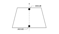
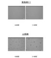
- FIG. It is a top view which shows one Embodiment of the windshield which concerns on this invention. It is sectional drawing of FIG. It is sectional drawing of a laminated glass. It is a schematic plan view which shows the measurement position of the thickness of a laminated glass. It is an example of the image used for the measurement of an intermediate film. It is a block diagram of the vehicle-mounted system arrange
- FIG. 1 is a plan view of the windshield
- FIG. 2 is a cross-sectional view of FIG.
- the vertical direction in FIG. 1 is referred to as “up and down”, “vertical”, and “vertical”, and the horizontal direction in FIG. 1 is referred to as “left and right”.
- FIG. 1 illustrates a windshield viewed from the inside of the vehicle. That is, the back side of the sheet of FIG. 1 is the outside of the vehicle, and the front side of the sheet of FIG. 1 is the inside of the vehicle.
- the windshield is provided with a substantially rectangular laminated glass 10 and is installed on the vehicle body in an inclined state.
- the inner surface 130 of the laminated glass 10 facing the vehicle interior is provided with a mask layer 110 that shields the field of view from the outside of the vehicle, and the photographing device 2 is arranged so as not to be seen from the outside of the vehicle by the mask layer 110.
- the photographing device 2 is a camera for photographing a situation outside the vehicle. Therefore, the mask layer 110 is provided with a photographing window 113 at a position corresponding to the photographing device 2, and the photographing device 2 disposed inside the vehicle through the photographing window 113 captures information on the situation outside the vehicle. Can be obtained. Further, an antifogging sheet 7 is attached to the photographing window 113.
- the information processing device 3 is connected to the photographing device 2, and information such as a photographed image acquired by the photographing device 2 is processed by the information processing device 3.
- the imaging device 2 and the information processing device 3 constitute an in-vehicle system 5, and the in-vehicle system 5 can provide various information to the passenger according to the processing of the information processing device 3.
- each component will be described.
- FIG. 3 is a sectional view of the laminated glass.
- the laminated glass 10 includes an outer glass plate 11 and an inner glass plate 12, and a resin intermediate film 13 is disposed between the glass plates 11 and 12.
- a resin intermediate film 13 is disposed between the glass plates 11 and 12.
- the outer glass plate 11 and the inner glass plate 12 will be described.
- known glass plates can be used, and they can be formed of heat ray absorbing glass, general clear glass, green glass, or UV green glass.
- these glass plates 11 and 12 need to realize visible light transmittance in accordance with the safety standards of the country where the automobile is used. For example, the required solar radiation absorption rate can be ensured by the outer glass plate 11, and the visible light transmittance can be adjusted by the inner glass plate 12 so as to satisfy safety standards. Examples of clear glass, green glass, heat ray absorbing glass, ultraviolet absorbing glass, and soda lime glass are shown below.
- the thickness of the laminated glass according to the present embodiment is not particularly limited, the total thickness of the outer glass plate 11 and the inner glass plate 12 can be set to 2.1 to 6 mm as an example, from the viewpoint of weight reduction.
- the total thickness is preferably 2.4 to 3.8 mm, more preferably 2.6 to 3.4 mm, and particularly preferably 2.7 to 3.2 mm.
- the thickness of each glass plate is not particularly limited,
- the thickness of the outer glass plate 11 and the inner glass plate 12 can be determined as follows.
- the outer glass plate 11 mainly needs durability and impact resistance against external obstacles. For example, when this laminated glass is used as a windshield of an automobile, the outer glass plate 11 has impact resistance performance against flying objects such as pebbles. is necessary. On the other hand, as the thickness is larger, the weight increases, which is not preferable. In this respect, the thickness of the outer glass plate 11 is preferably 1.8 to 2.3 mm, and more preferably 1.9 to 2.1 mm. Which thickness is adopted can be determined according to the application of the glass.
- the thickness of the inner glass plate 12 can be made equal to that of the outer glass plate 11, but for example, the thickness can be made smaller than that of the outer glass plate 11 in order to reduce the weight of the laminated glass. Specifically, considering the strength of the glass, it is preferably 0.6 to 2.0 mm, more preferably 0.8 to 1.6 mm, and particularly preferably 1.0 to 1.4 mm. preferable. Further, it is preferably 0.8 to 1.3 mm. Which thickness is used for the inner glass plate 12 can be determined according to the purpose of the glass.
- the measuring instrument is not particularly limited, and for example, a thickness gauge such as SM-112 manufactured by Teclock Co., Ltd. can be used.
- SM-112 manufactured by Teclock Co., Ltd.
- Teclock Co., Ltd. Teclock Co., Ltd.
- it is arranged so that the curved surface of the glass plate is placed on a flat surface, and the end of the glass plate is sandwiched by the thickness gauge and measured. Even when the glass plate is flat, it can be measured in the same manner as when the glass plate is curved.
- the intermediate film 13 is formed of at least one layer.
- the intermediate film 13 can be configured by three layers in which a soft core layer 131 is sandwiched between harder outer layers 132.
- it is not limited to this configuration, and may be formed of a plurality of layers including the core layer 131 and at least one outer layer 132 disposed on the outer glass plate 11 side.
- the intermediate film 13 may be disposed, or the intermediate film 13 may be configured such that the odd outer layer 132 is disposed on one side and the even outer layer 132 is disposed on the other side with the core layer 131 interposed therebetween.
- the outer layer 132 is provided on the outer glass plate 11 side as described above, but this is to improve the resistance to breakage against an external force from outside the vehicle or outside. Further, when the number of outer layers 132 is large, the sound insulation performance is also enhanced.
- the hardness thereof is not particularly limited.
- the material which comprises each layer 131,132 is not specifically limited, For example, a material can be selected on the basis of a Young's modulus. Specifically, it is preferably 1 to 20 MPa, more preferably 1 to 18 MPa, and particularly preferably 1 to 14 MPa at a frequency of 100 Hz and a temperature of 20 degrees. With such a range, it is possible to prevent the STL from decreasing in a low frequency range of approximately 3500 Hz or less.
- the Young's modulus of the outer layer 132 is preferably large in order to improve sound insulation performance in a high frequency region, as will be described later, and is 560 MPa or more, 600 MPa or more, 650 MPa or more, 700 MPa or more at a frequency of 100 Hz and a temperature of 20 degrees. It can be set to 750 MPa or more, 880 MPa or more, or 1300 MPa or more.
- the upper limit of the Young's modulus of the outer layer 132 is not particularly limited, but can be set from the viewpoint of workability, for example. For example, it is empirically known that when it becomes 1750 MPa or more, workability, particularly cutting becomes difficult.
- the outer layer 132 can be made of, for example, polyvinyl butyral resin (PVB).
- PVB polyvinyl butyral resin
- the core layer 131 can be made of, for example, an ethylene vinyl acetate resin (EVA) or a polyvinyl acetal resin that is softer than the polyvinyl butyral resin constituting the outer layer.
- the hardness of the polyvinyl acetal resin is controlled by (a) the degree of polymerization of the starting polyvinyl alcohol, (b) the degree of acetalization, (c) the type of plasticizer, (d) the addition ratio of the plasticizer, etc. Can do. Therefore, by appropriately adjusting at least one selected from these conditions, a hard polyvinyl butyral resin used for the outer layer 132 and a soft polyvinyl butyral resin used for the core layer 131 even if the same polyvinyl butyral resin is used. Can be made separately.
- the hardness of the polyvinyl acetal resin can also be controlled by the type of aldehyde used for acetalization, coacetalization with a plurality of aldehydes, or pure acetalization with a single aldehyde. Although it cannot generally be said, the polyvinyl acetal resin obtained by using an aldehyde having a large number of carbon atoms tends to be softer.
- the core layer 131 has an aldehyde having 5 or more carbon atoms (for example, n-hexylaldehyde, 2-ethylbutyraldehyde, n-heptylaldehyde, n-octylaldehyde) and a polyvinyl acetal resin obtained by acetalization with polyvinyl alcohol can be used.
- a predetermined Young's modulus it is not limited to the said resin.
- the total thickness of the intermediate film 13 is not particularly limited, but is preferably 0.3 to 6.0 mm, more preferably 0.5 to 4.0 mm, and 0.6 to 2.0 mm. It is particularly preferred.
- the thickness of the core layer 131 is preferably 0.1 to 2.0 mm, and more preferably 0.1 to 0.6 mm.
- the thickness of each outer layer 132 is preferably 0.1 to 2.0 mm, and more preferably 0.1 to 1.0 mm.
- the total thickness of the intermediate film 13 can be made constant, and the thickness of the core layer 131 can be adjusted therein.
- the thickness of the core layer 131 and the outer layer 132 can be measured as follows, for example. First, the cross section of the laminated glass is enlarged and displayed by 175 times using a microscope (for example, VH-5500 manufactured by Keyence Corporation). And the thickness of the core layer 131 and the outer layer 132 is specified visually, and this is measured. At this time, in order to eliminate visual variation, the number of measurements is set to 5 times, and the average value is defined as the thickness of the core layer 131 and the outer layer 132. For example, an enlarged photograph of a laminated glass as shown in FIG. 7 is taken, and the core layer and the outer layer 132 are specified in this and the thickness is measured.
- the thickness of the core layer 131 and the outer layer 132 of the intermediate film 13 does not need to be constant over the entire surface, and can be a wedge shape for laminated glass used for a head-up display, for example.
- the thickness of the core layer 131 and the outer layer 132 of the intermediate film 13 is measured at the position where the thickness is the smallest, that is, the lowermost side portion of the laminated glass.
- the intermediate film 13 is wedge-shaped, the outer glass plate and the inner glass plate are not arranged in parallel, but such arrangement is also included in the glass plate in the present invention.
- the present invention includes, for example, the arrangement of the outer glass plate and the inner glass plate when the intermediate film 13 using the core layer 131 or the outer layer 132 whose thickness is increased at a rate of change of 3 mm or less per meter is used. .
- the method for producing the intermediate film 13 is not particularly limited.
- the resin component such as the polyvinyl acetal resin described above, a plasticizer, and other additives as necessary are blended and kneaded uniformly, and then each layer is collectively And a method of laminating two or more resin films prepared by this method by a pressing method, a laminating method or the like.
- the resin film before lamination used in a method of laminating by a press method, a laminating method or the like may have a single layer structure or a multilayer structure.
- the intermediate film 13 can be formed of a single layer in addition to the above-described plural layers.
- the windshield according to the present embodiment captures the outside of the vehicle by the information acquisition device, the windshield needs to have a visible light transmittance to such an extent that the situation outside the vehicle can be captured. Accordingly, the visible light transmittance is configured to be 70% or more.
- permeability can be measured by the spectroscopic measurement method prescribed
- the ultraviolet transmittance as a laminated glass is as follows. Tuv380 ⁇ 0.5% and Tuv400 ⁇ 3.5% (1)
- Tuv380 is the ultraviolet transmittance defined in ISO9050: 1990
- Tuv400 is the ultraviolet transmittance defined in ISO13837: 2008 convention A.
- the ultraviolet transmittance can be measured with a known spectrophotometer, for example, “UV-3100PC” (manufactured by Shimadzu Corporation).
- Tuv400 in the above formula (1) is preferably 2.5% or less, more preferably 2.0% or less, and particularly preferably 1.0% or less.
- the laminated glass of the present invention is constituted including the following constitutions (1) to (3).
- the laminated glass is formed of green glass, heat ray absorbing glass, or ultraviolet absorbing glass.
- the laminated glass using these satisfies the above formula (1) as described later.
- a film having ultraviolet shielding properties is provided on at least one of the inner side surface of the inner glass plate and the inner side surface of the inner glass plate and the antifogging sheet.
- Examples of the film having an ultraviolet shielding property include an organic-inorganic composite film containing an ultraviolet absorber and a light-resistant film.
- the organic-inorganic composite film may be, for example, a film containing a hydrolysis-condensation product of tetrafunctional silicon alkoxide, a hydrolysis-condensation product of trifunctional silicon alkoxide, an ultraviolet absorber that is an organic material, and an organic polymer. it can.
- the light-resistant film is, for example, a polyester film that can contain 0.05 to 30% by mass of an ultraviolet absorber.
- An ultraviolet absorbing performance is imparted to the intermediate film.
- an intermediate film having a long wavelength ultraviolet absorption function can be used.
- an intermediate film containing an ultraviolet absorber (for example, one containing more than usual) or an intermediate film containing a specific light absorber can be used.
- the light absorber for example, one having an anthraquinone structure having a thiophenyl group can be employed. Thereby, the ultraviolet transmittance can be reduced without reducing the visible light transmittance.
- the light absorber having such an anthraquinone structure may have at least one or more thiophenyl groups, and preferably has two or more thiophenyl groups.
- the lower limit of the content of the light absorber having an anthraquinone structure with respect to the intermediate film is, for example, 0.003 parts by weight with respect to 100 parts by weight of the thermoplastic resin, and the upper limit is, for example, 0.007 parts by weight. it can.
- interposed the intermediate film containing such a light absorber about 0.0035 weight part with clear glass can make Tuv380 0% and Tuv400 about 2.8%.
- the ultraviolet transmittance can be further reduced.
- the mask layer 110 is laminated on the inner surface 130 (the inner surface of the inner glass plate 12) 130 of the laminated glass 10, and on the peripheral edge of the laminated glass 10. Are formed along.
- the mask layer 110 according to the present embodiment protrudes in a rectangular shape downward from the peripheral region 111 along the peripheral portion of the laminated glass 10 and the upper side portion of the laminated glass 10.
- the protruding region 112 can be divided.
- the peripheral region 111 shields light incident from the peripheral portion of the windshield 1.
- the protruding region 112 prevents the photographing device 2 disposed in the vehicle from being seen from outside the vehicle.
- a rectangular information acquisition region (opening) 113 is provided at a position corresponding to the photographing device 2 in the protruding region 112 of the mask layer 110 so that the photographing device 2 can be in a situation outside the vehicle. It has been. That is, the imaging window 113 is provided independently from the non-shielding region 120 on the inner side in the plane direction from the mask layer 110. Further, the photographing window 113 is a region where the material of the mask layer 110 is not laminated, and the laminated glass has the above-described visible light transmittance, so that the situation outside the vehicle can be photographed.
- the mask layer 110 can be laminated on the inner surface of the outer glass plate 11 and the outer surface of the inner glass plate 12, for example, in addition to the inner layer of the inner glass plate 12 as described above. Moreover, it can also laminate
- the material of the mask layer 110 may be appropriately selected according to the embodiment as long as the field of view from the outside of the vehicle can be blocked.
- a dark ceramic such as black, brown, gray, or dark blue is used. Also good.
- black ceramic is selected as the material of the mask layer 110
- black ceramic is laminated on the peripheral portion on the inner surface 130 of the inner glass plate 12 by screen printing or the like, and the ceramic laminated with the inner glass plate 12 is heated. To do. Thereby, the mask layer 110 can be formed on the peripheral edge of the inner glass plate 12. Moreover, when printing black ceramic, the area
- various materials can be used for the ceramic used for the mask layer 110. For example, a ceramic having the composition shown in Table 1 below can be used for the mask layer 110.
- Main component Copper oxide, Chromium oxide, Iron oxide and Manganese oxide * 2
- Main component Bismuth borosilicate, Zinc borosilicate
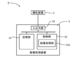
- FIG. 6 illustrates the configuration of the in-vehicle system 5.
- the in-vehicle system 5 according to the present embodiment includes the imaging device 2 and an image processing device 3 connected to the imaging device 2.
- the image processing device 3 is a device that processes the captured image acquired by the imaging device 2.
- the image processing apparatus 3 includes, for example, general hardware such as a storage unit 31, a control unit 32, and an input / output unit 33 connected by a bus as a hardware configuration.
- general hardware such as a storage unit 31, a control unit 32, and an input / output unit 33 connected by a bus as a hardware configuration.
- the hardware configuration of the image processing apparatus 3 does not have to be limited to such an example, and the specific hardware configuration of the image processing apparatus 3 is appropriately added or omitted according to the embodiment. And additions are possible.
- the storage unit 31 stores various data and programs used in processing executed by the control unit 32 (not shown).
- the storage unit 31 may be realized, for example, by a hard disk or a recording medium such as a USB memory.
- the various data and programs stored in the storage unit 31 may be acquired from a recording medium such as a CD (Compact Disc) or a DVD (Digital Versatile Disc).
- the storage unit 31 may be referred to as an auxiliary storage device.
- the laminated glass 10 is disposed in an inclined posture with respect to the vertical direction and is curved.
- the imaging device 2 images the situation outside the vehicle through such a laminated glass 10. Therefore, the captured image acquired by the imaging device 2 is deformed according to the posture, shape, refractive index, optical defect, and the like of the laminated glass 10.
- the storage unit 31 may store correction data for correcting the image deformed due to the aberration of the laminated glass 10 and the camera lens.
- the control unit 32 includes one or more processors such as a microprocessor or a CPU (Central Processing Unit), and peripheral circuits (ROM (Read Only Memory), RAM (Random Access Memory), an interface circuit) used for processing of the processor. Etc.). ROM, RAM, and the like may be referred to as a main storage device in the sense that they are arranged in an address space handled by the processor in the control unit 32.
- the control unit 32 functions as the image processing unit 321 by executing various data and programs stored in the storage unit 31.
- the image processing unit 321 processes the captured image acquired by the imaging device 2.
- the processing of the captured image can be selected as appropriate according to the embodiment.
- the image processing unit 321 may recognize the subject appearing in the captured image by analyzing the captured image by pattern matching or the like.
- the image processing unit 321 since the imaging device 2 captures a situation in front of the vehicle, the image processing unit 321 further determines whether or not a living organism such as a human is captured in front of the vehicle based on the subject recognition. Also good.
- the image processing unit 321 may output a warning message by a predetermined method. Further, for example, the image processing unit 321 may perform a predetermined processing on the captured image. Then, the image processing unit 321 may output the processed photographed image to a display device (not shown) such as a display connected to the image processing device 3.
- the input / output unit 33 is one or a plurality of interfaces for transmitting / receiving data to / from an apparatus existing outside the image processing apparatus 3.
- the input / output unit 33 is, for example, an interface for connecting to a user interface or an interface such as USB (Universal Serial Bus).
- the image processing apparatus 3 is connected to the photographing apparatus 2 via the input / output unit 33 and acquires a photographed image photographed by the photographing apparatus 2.
- Such an image processing device 3 may be a general-purpose device such as a PC (Personal Computer) or a tablet terminal in addition to a device designed exclusively for the service to be provided.
- PC Personal Computer
- tablet terminal in addition to a device designed exclusively for the service to be provided.
- the information acquisition device is attached to a bracket (not shown), and this bracket is attached to the mask layer. Therefore, in this state, the attachment of the information acquisition device to the bracket and the attachment of the bracket to the mask layer are adjusted so that the optical axis of the camera of the information acquisition device passes through the information acquisition region.
- a cover (not shown) is attached to the bracket so as to cover the photographing apparatus 2. Therefore, the photographing device 2 is arranged in a space surrounded by the laminated glass 10, the bracket, and the cover so that it cannot be seen from the inside of the vehicle and only a part of the photographing device 2 can be seen from the outside of the vehicle through the photographing window 113. There is no such thing.
- the photographing apparatus 2 and the above-described input / output unit 33 are connected by a cable (not shown). The cable is pulled out from the cover and connected to the image processing apparatus 3 arranged at a predetermined position in the vehicle. .
- the antifogging sheet As described above, the antifogging sheet is affixed to the information acquisition area, and as shown in FIG. 7, the adhesive layer 71, the base film 72, and the antifogging layer 73 are laminated in this order. It is. Further, the first protective sheet 74 that can be peeled off is attached to the adhesive layer 71 and the second protective sheet 75 that can be peeled off is attached to the anti-fogging layer 73 until they are fixed to the information acquisition area.
- the anti-fogging laminated body is comprised by.
- the antifogging sheet 7 is formed in a shape corresponding to the photographing window 113, but can be formed in a shape slightly smaller than the photographing window 113, for example. Alternatively, it may be formed so as to be larger than the photographing window 113 and to cover a part of the mask layer 110 beyond the photographing window 113.
- each layer will be described.
- the anti-fogging layer is not particularly limited as long as the anti-fogging effect of the laminated glass plate 10 is exhibited, and a known one can be used.
- the antifogging layer has a hydrophilic type in which water generated from water vapor is formed on the surface as a water film, a water absorption type that absorbs water vapor, a water-repellent water absorption type in which water droplets are less likely to condense on the surface, and water droplets generated from water vapor.
- a water-repellent type that waters
- any type of anti-fogging layer is applicable. Below, the example of the water-repellent water absorption type anti-fogging layer is demonstrated as the example.
- the organic-inorganic composite antifogging layer is a single layer film formed on the surface of the base film or a multilayer film laminated.
- the organic-inorganic composite antifogging layer contains at least a water absorbent resin, a water repellent group, and a metal oxide component.
- the antifogging film may further contain other functional components as necessary.
- the type of water-absorbing resin is not limited as long as it can absorb and retain water.
- the water repellent group can be supplied to the antifogging film from a metal compound having a water repellent group (water repellent group-containing metal compound).
- the metal oxide component can be supplied to the antifogging film from a water repellent group-containing metal compound, other metal compounds, metal oxide fine particles and the like.
- each component will be described.
- Water absorbent resin there is no particular limitation as the water absorbent resin, polyethylene glycol, polyether resin, polyurethane resin, starch resin, cellulose resin, acrylic resin, epoxy resin, polyester polyol, hydroxyalkyl cellulose, polyvinyl alcohol, polyvinyl pyrrolidone, A polyvinyl acetal resin, polyvinyl acetate, etc. are mentioned. Among these, preferred are hydroxyalkyl cellulose, polyvinyl alcohol, polyvinyl pyrrolidone, polyvinyl acetal resin, polyvinyl acetate, epoxy resin and polyurethane resin, and more preferred are polyvinyl acetal resin, epoxy resin and polyurethane resin. Among them, polyvinyl acetal resin is particularly preferable.
- the polyvinyl acetal resin can be obtained by subjecting polyvinyl alcohol to an acetalization by a condensation reaction of aldehyde with polyvinyl alcohol.
- the acetalization of polyvinyl alcohol may be carried out using a known method such as a precipitation method using an aqueous medium in the presence of an acid catalyst, or a dissolution method using a solvent such as alcohol.
- Acetalization can also be carried out in parallel with saponification of polyvinyl acetate.
- the degree of acetalization is preferably 2 to 40 mol%, more preferably 3 to 30 mol%, particularly 5 to 20 mol%, and in some cases 5 to 15 mol%.
- the degree of acetalization can be measured based on, for example, 13 C nuclear magnetic resonance spectroscopy.
- a polyvinyl acetal resin having an acetalization degree in the above range is suitable for forming an organic-inorganic composite antifogging layer having good water absorption and water resistance.
- the average degree of polymerization of polyvinyl alcohol is preferably 200 to 4500, more preferably 500 to 4500.
- a high average degree of polymerization is advantageous for the formation of an organic-inorganic composite antifogging layer having good water absorption and water resistance, but if the average degree of polymerization is too high, the viscosity of the solution becomes too high, which hinders film formation. I have come.
- the saponification degree of polyvinyl alcohol is preferably 75 to 99.8 mol%.
- aldehyde to be subjected to a condensation reaction with polyvinyl alcohol examples include aliphatic aldehydes such as formaldehyde, acetaldehyde, butyraldehyde, hexyl carbaldehyde, octyl carbaldehyde, decyl carbaldehyde.
- benzaldehyde 2-methylbenzaldehyde, 3-methylbenzaldehyde, 4-methylbenzaldehyde, other alkyl group-substituted benzaldehydes; chlorobenzaldehyde, other halogen atom-substituted benzaldehydes; alkyl such as hydroxy group, alkoxy group, amino group, cyano group
- aromatic aldehydes such as condensed aromatic aldehydes such as naphthaldehyde and anthraldehyde.
- Aromatic aldehydes having strong hydrophobicity are advantageous in forming an organic-inorganic composite antifogging layer having a low degree of acetalization and excellent water resistance.
- the use of an aromatic aldehyde is also advantageous in forming a film having high water absorption while leaving many hydroxyl groups remaining.
- the polyvinyl acetal resin preferably contains an acetal structure derived from an aromatic aldehyde, particularly benzaldehyde.
- epoxy resin examples include glycidyl ether epoxy resin, glycidyl ester epoxy resin, glycidyl amine epoxy resin, and cyclic aliphatic epoxy resin. Of these, cycloaliphatic epoxy resins are preferred.
- polyurethane resin examples include a polyurethane resin composed of a polyisocyanate and a polyol.
- a polyurethane resin composed of a polyisocyanate and a polyol.
- the polyol an acrylic polyol and a polyoxyalkylene polyol are preferable.
- the organic / inorganic composite antifogging layer is mainly composed of a water-absorbing resin.
- the “main component” means a component having the highest content on a mass basis.
- the content of the water absorbent resin based on the weight of the organic / inorganic composite antifogging layer is preferably 50% by weight or more, more preferably 60% by weight or more, and particularly preferably 65% from the viewpoint of film hardness, water absorption and antifogging property. It is 95% by weight or less, more preferably 90% by weight or less, and particularly preferably 85% by weight or less.
- water repellent group In order to sufficiently obtain the above-described effects due to the water repellent group, it is preferable to use a water repellent group having high water repellency.
- Preferred water repellent groups are (1) a chain or cyclic alkyl group having 3 to 30 carbon atoms, and (2) a chain or cyclic group having 1 to 30 carbon atoms in which at least a part of hydrogen atoms are substituted with fluorine atoms. It is at least one selected from alkyl groups (hereinafter sometimes referred to as “fluorine-substituted alkyl groups”).
- the chain or cyclic alkyl group is preferably a chain alkyl group.
- the chain alkyl group may be a branched alkyl group, but is preferably a linear alkyl group.
- An alkyl group having more than 30 carbon atoms may cause the antifogging film to become cloudy.
- the carbon number of the alkyl group is preferably 20 or less, more preferably 6 to 14.
- alkyl groups are linear alkyl groups having 6 to 14 carbon atoms, particularly 6 to 12 carbon atoms, such as n-hexyl group (6 carbon atoms), n-decyl group (10 carbon atoms), n-dodecyl group ( 12).
- the fluorine-substituted alkyl group may be a group in which only part of the hydrogen atoms of the chain or cyclic alkyl group is substituted with fluorine atoms, and all of the hydrogen atoms of the chain or cyclic alkyl group. May be a group substituted with a fluorine atom, for example, a linear perfluoroalkyl group.
- the fluorine-substituted alkyl group has high water repellency, a sufficient effect can be obtained by adding a small amount. However, if the content of the fluorine-substituted alkyl group is too large, it may be separated from other components in the coating solution for forming a film.
- a metal compound having a water repellent group water repellent group-containing metal compound
- a metal compound having a water repellent group and a hydrolyzable functional group or a halogen atom A water repellent group-containing hydrolyzable metal compound) or a hydrolyzate thereof may be added to a coating solution for forming a film.
- the water repellent group may be derived from a water repellent group-containing hydrolyzable metal compound.
- the water repellent group-containing hydrolyzable metal compound is preferably a water repellent group-containing hydrolyzable silicon compound represented by the following formula (I).
- R is a water repellent group, that is, a linear or cyclic alkyl group having 1 to 30 carbon atoms in which at least part of hydrogen atoms may be substituted with fluorine atoms
- Y is a hydrolyzable functional group.
- a group or a halogen atom, and m is an integer of 1 to 3.
- the hydrolyzable functional group is, for example, at least one selected from an alkoxyl group, an acetoxy group, an alkenyloxy group, and an amino group, preferably an alkoxy group, particularly an alkoxy group having 1 to 4 carbon atoms.
- An alkenyloxy group is, for example, an isopropenoxy group.
- the halogen atom is preferably chlorine.
- the functional groups exemplified here can also be used as “hydrolyzable functional groups” described below.
- m is preferably 1 to 2.
- the compound represented by formula (I) supplies the component represented by the following formula (II) when hydrolysis and polycondensation have completely proceeded.
- R and m are as described above.
- the compound represented by formula (II) actually forms a network structure in which silicon atoms are bonded to each other through oxygen atoms in the antifogging film.
- the compound represented by the formula (I) is hydrolyzed or partially hydrolyzed, and further, at least partly polycondensed to alternately connect silicon atoms and oxygen atoms, and three-dimensionally.
- a network structure of spreading siloxane bonds Si—O—Si
- a water repellent group R is connected to silicon atoms included in the network structure.
- the water repellent group R is fixed to the network structure of the siloxane bond through the bond R—Si. This structure is advantageous in uniformly dispersing the water repellent group R in the film.
- the network structure may contain a silica component supplied from a silicon compound (for example, tetraalkoxysilane, silane coupling agent) other than the water repellent group-containing hydrolyzable silicon compound represented by the formula (I).
- a silica component supplied from a silicon compound for example, tetraalkoxysilane, silane coupling agent
- a hydrolyzable silicon compound having no water repellent group and a hydrolyzable functional group or halogen atom water repellent group-free hydrolyzable silicon compound
- a network structure of siloxane bonds including silicon atoms bonded to water repellent groups and silicon atoms not bonded to water repellent groups can be formed. With such a structure, it becomes easy to adjust the water repellent group content and the metal oxide component content in the antifogging film independently of each other.
- the water repellent group has an effect of improving the antifogging performance by improving the water vapor permeability on the surface of the antifogging film containing the water-absorbing resin. Since the two functions of water absorption and water repellency are contradictory to each other, the water-absorbing material and the water-repellent material have been conventionally assigned to different layers, but the water-repellent group is located near the surface of the antifogging layer. Eliminates the uneven distribution of water, prolongs the time until condensation, and improves the antifogging property of the antifogging film having a single layer structure. The effect will be described below.
- Water vapor that has entered the anti-fogging film containing the water-absorbing resin is hydrogen-bonded with a hydroxyl group of the water-absorbing resin or the like, and is retained in the form of bound water. As the amount increases, the water vapor is retained from the bound water form to the semi-bound water form and finally to the free water form retained in the voids in the antifogging membrane.
- the water repellent group prevents the formation of hydrogen bonds and facilitates the dissociation of the formed hydrogen bonds. If the content of the water-absorbing resin is the same, there is no difference in the number of hydroxyl groups capable of hydrogen bonding in the film, but the water-repellent group reduces the rate of hydrogen bond formation.
- the anti-fogging film containing a water repellent group moisture is finally retained in the film in any of the above forms, but by the time it is retained, it remains as water vapor up to the bottom of the film. Can diffuse. Also, the water once retained is easily dissociated and easily moves to the bottom of the membrane in the state of water vapor. As a result, the distribution of moisture retention in the film thickness direction is relatively uniform from the vicinity of the surface to the bottom of the film. That is, since all of the thickness direction of the anti-fogging film can be effectively utilized and water supplied to the film surface can be absorbed, water droplets hardly condense on the surface and the anti-fogging property is improved.
- the anti-fogging film that has absorbed moisture has a feature that it is difficult to freeze even at low temperatures because water droplets are less likely to condense on the surface. Therefore, when this anti-fogging film is fixed to the information acquisition region, the field of view of the information acquisition region can be secured in a wide temperature range.
- a water-repellent group is introduced into an antifogging film using a water-repellent group-containing hydrolyzable silicon compound (see formula (I))
- a strong siloxane bond (Si—O—Si) network structure is formed.
- the formation of this network structure is advantageous not only from the viewpoint of wear resistance but also from the viewpoint of improving hardness, water resistance and the like.
- the water repellent group may be added to such an extent that the contact angle of water on the surface of the antifogging film is 70 degrees or more, preferably 80 degrees or more, more preferably 90 degrees or more.
- the contact angle of water a value measured by dropping a 4 mg water droplet on the surface of the membrane is adopted.
- a methyl group or an ethyl group having a slightly weak water repellency is used as the water repellent group, it is preferable to add an amount of the water repellent group having a water contact angle in the above range to the antifogging film.
- the upper limit of the contact angle of the water droplet is not particularly limited, but is, for example, 150 degrees or less, for example, 120 degrees or less, and further 100 degrees or less. It is preferable that the water repellent group be uniformly contained in the antifogging film so that the contact angle of the water droplets is in the above range in all regions of the surface of the antifogging film.
- the anti-fogging film is 0.05 parts by mass or more, preferably 0.1 parts by mass or more, more preferably 0.3 parts by mass or more with respect to 100 parts by mass of the water absorbent resin. It is preferable that a water repellent group is contained so that it may become in the range of 5 parts by mass or less, preferably 5 parts by mass or less.
- the inorganic oxide is, for example, an oxide of at least one element selected from Si, Ti, Zr, Ta, Nb, Nd, La, Ce, and Sn, and includes at least an Si oxide (silica).
- the organic / inorganic composite antifogging layer is preferably 0.01 parts by weight or more, more preferably 0.1 parts by weight or more, still more preferably 0.2 parts by weight or more, particularly preferably 100 parts by weight of the water-absorbing resin.
- the inorganic oxide is a component necessary for ensuring the strength of the organic-inorganic composite antifogging layer, particularly the abrasion resistance. However, when the content of the inorganic oxide increases, the antifogging property of the organic-inorganic composite antifogging layer decreases. .
- the organic-inorganic composite antifogging layer may further contain inorganic oxide fine particles as at least a part of the inorganic oxide.
- the inorganic oxide constituting the inorganic oxide fine particles is, for example, an oxide of at least one element selected from Si, Ti, Zr, Ta, Nb, Nd, La, Ce and Sn, preferably silica fine particles. is there.
- the silica fine particles can be introduced into the organic-inorganic composite antifogging layer by adding, for example, colloidal silica.
- the inorganic oxide fine particles are excellent in the action of transmitting the stress applied to the organic-inorganic composite antifogging layer to the article supporting the organic-inorganic composite antifogging layer, and have high hardness. Therefore, the addition of inorganic oxide fine particles is advantageous from the viewpoint of improving the wear resistance of the organic-inorganic composite antifogging layer.
- inorganic oxide fine particles when inorganic oxide fine particles are added to the organic-inorganic composite antifogging layer, fine voids are formed at sites where the fine particles are in contact with or close to, and water vapor is easily taken into the film from the voids. For this reason, the addition of inorganic oxide fine particles may sometimes have an advantageous effect on improving the antifogging property.
- the inorganic oxide fine particles can be supplied to the organic / inorganic composite antifogging layer by adding the inorganic oxide fine particles formed in advance to the coating liquid for forming the organic / inorganic composite antifogging layer.
- the average particle size of the inorganic oxide fine particles is preferably 1 to 20 nm, and more preferably 5 to 20 nm.
- the average particle diameter of the inorganic oxide fine particles is described in the state of primary particles. The average particle size of the inorganic oxide fine particles is determined by measuring the particle sizes of 50 fine particles arbitrarily selected by observation using a scanning electron microscope and adopting the average value.
- the inorganic oxide fine particles are preferably 0 to 50 parts by weight, more preferably 2 to 30 parts by weight, still more preferably 5 to 25 parts by weight, and particularly preferably 10 to 20 parts by weight with respect to 100 parts by weight of the water absorbent resin. It is good to add so that it may become a part.
- the anti-fogging film may contain a metal oxide component derived from a hydrolyzable metal compound having no water-repellent group (water-repellent group-free hydrolyzable compound).
- a preferred hydrolyzable metal compound containing no water repellent group is a hydrolyzable silicon compound having no water repellent group.
- the hydrolyzable silicon compound having no water repellent group is, for example, at least one silicon compound selected from silicon alkoxide, chlorosilane, acetoxysilane, alkenyloxysilane and aminosilane (however, having no water repellent group), Silicon alkoxide having no water repellent group is preferred.
- An example of alkenyloxysilane is isopropenoxysilane.
- the hydrolyzable silicon compound having no water repellent group may be a compound represented by the following formula (III). SiY4 (III)
- Y is a hydrolyzable functional group, preferably at least one selected from an alkoxyl group, an acetoxy group, an alkenyloxy group, an amino group, and a halogen atom.
- the water repellent group-free hydrolyzable metal compound is hydrolyzed or partially hydrolyzed, and further, at least a part thereof is polycondensed to supply a metal oxide component in which a metal atom and an oxygen atom are bonded.
- This component can strongly bond the metal oxide fine particles and the water-absorbent resin, and can contribute to improvement of the wear resistance, hardness, water resistance, etc. of the antifogging film.
- the metal oxide component derived from the hydrolyzable metal compound having no water repellent group is 0 to 40 parts by mass, preferably 0.1 to 30 parts by mass, more preferably 1 to 1 part by mass with respect to 100 parts by mass of the water absorbent resin. It may be 20 parts by mass, particularly preferably 3 to 10 parts by mass, and in some cases 4 to 12 parts by mass.
- a preferred example of the hydrolyzable silicon compound having no water repellent group is tetraalkoxysilane, more specifically, tetraalkoxysilane having an alkoxy group having 1 to 4 carbon atoms.
- Tetraalkoxysilanes include, for example, tetramethoxysilane, tetraethoxysilane, tetra-n-propoxysilane, tetraisopropoxysilane, tetra-n-butoxysilane, tetraisobutoxysilane, tetra-sec-butoxysilane, and tetra-tert- It is at least one selected from butoxysilane.
- the metal oxide component derived from tetraalkoxysilane may be added in the range of 0 to 30 parts by mass, preferably 1 to 20 parts by mass, more preferably 3 to 10 parts by mass with respect to 100 parts by mass of the water absorbent resin.
- silane coupling agents are silicon compounds having different reactive functional groups. A part of the reactive functional group is preferably a hydrolyzable functional group.
- the silane coupling agent is, for example, a silicon compound having an epoxy group and / or an amino group and a hydrolyzable functional group.
- preferable silane coupling agents include glycidyloxyalkyltrialkoxysilane and aminoalkyltrialkoxysilane. In these silane coupling agents, the number of carbon atoms of the alkylene group directly bonded to the silicon atom is preferably 1 to 3.
- the glycidyloxyalkyl group and the aminoalkyl group include a functional group (epoxy group or amino group) that exhibits hydrophilicity, the glycidyloxyalkyl group and the aminoalkyl group are not water-repellent as a whole although they include an alkylene group.
- the silane coupling agent strongly binds the water-absorbing resin that is an organic component and the metal oxide fine particles that are an inorganic component, and can contribute to the improvement of wear resistance, hardness, water resistance, and the like of the antifogging film.
- the metal oxide component derived from the silane coupling agent is in the range of 0 to 10 parts by weight, preferably 0.05 to 5 parts by weight, more preferably 0.1 to 2 parts by weight with respect to 100 parts by weight of the water absorbent resin. Should be added.
- the antifogging film may include a crosslinked structure derived from a crosslinking agent, preferably at least one crosslinking agent selected from an organic boron compound, an organic titanium compound, and an organic zirconium compound.
- a crosslinked structure improves the wear resistance, scratch resistance and water resistance of the antifogging film. From another viewpoint, the introduction of a crosslinked structure facilitates improving the durability of the antifogging film without deteriorating the antifogging performance.
- the antifogging film When a crosslinked structure derived from a crosslinking agent is introduced into the antifogging film in which the metal oxide component is a silica component, the antifogging film has a metal atom other than silicon as a metal atom, preferably boron, titanium or zirconium, May be contained.
- the type of the crosslinking agent is not particularly limited as long as it can crosslink the water-absorbing resin to be used.
- the organic titanium compound is, for example, at least one selected from titanium alkoxide, titanium chelate compound, and titanium acylate.
- the titanium alkoxide is, for example, titanium tetraisopropoxide, titanium tetra-n-butoxide, or titanium tetraoctoxide.
- the titanium chelate compound include titanium acetylacetonate, titanium ethylacetoacetate, titanium octylene glycol, titanium triethanolamine, and titanium lactate.
- the titanium lactate may be an ammonium salt (titanium lactate ammonium).
- the titanium acylate is, for example, titanium stearate.
- Preferred organic titanium compounds are titanium chelate compounds, particularly titanium lactate.
- a preferable cross-linking agent is an organic titanium compound, particularly titanium lactate.
- Additives may be surfactants, leveling agents, ultraviolet absorbers, colorants, antifoaming agents, preservatives, and the like.
- the silicon alkoxide preferably contains a silane coupling agent.
- light shielding for example, ultraviolet shielding
- the reason why the light shielding property of the organic-inorganic composite antifogging layer is improved by the silane coupling agent is that the light absorbing agent which is an organic compound is more uniformly dispersed in the water-absorbing resin containing silica by the addition of the silane coupling agent. It is thought that it is to become.
- ultraviolet absorbers examples include benzotriazole compounds [2- (2′-hydroxy-5′-methylphenyl) benzotriazole, 2- (2′-hydroxy-3 ′, 5′-di-t-butylphenyl)].
- Benzotriazole, etc. benzophenone compounds [2,2 ′, 4,4′-tetrahydroxybenzophenone, 2,4-dihydroxybenzophenone, 2-hydroxy-4-methoxybenzophenone, 2-hydroxy-4-octoxybenzophenone, 5, 5′-methylenebis (2-hydroxy-4-methoxybenzophenone) etc.]
- hydroxyphenyltriazine compound [2- (2-hydroxy-4-octoxyphenyl) -4,6-bis (2,4-di-t- Butylphenyl) -s-triazine, 2- (2-hydroxy-4-methoxyphenyl) Nyl) -4,6-diphenyl-s-triazine, 2- (2-hydroxy-4-propoxy-5-methylpheny
- An ultraviolet absorber may be used independently and may use 2 or more types together.
- the ultraviolet absorber may be at least one organic dye selected from a polymethine compound, an imidazoline compound, a coumarin compound, a naphthalimide compound, a perylene compound, an azo compound, an isoindolinone compound, a quinophthalone compound, and a quinoline compound.
- an ultraviolet absorber that is an organic substance is preferable, and more preferable is at least one selected from a benzotriazole compound, a benzophenone compound, a hydroxyphenyltriazine compound, and a cyanoacrylate compound, and more preferable. Is a benzophenone compound.
- a benzophenone compound is preferable because it has good solubility in an alcohol-based solvent contained in a coating solution for forming an organic-inorganic composite antifogging layer and is uniformly dispersed by a polyvinyl acetal resin.
- the ultraviolet absorber preferably has a hydroxyl group, and more preferably one having two or more hydroxyl groups bonded to one benzene skeleton of the ultraviolet absorber.
- the ultraviolet absorber is preferably added in an amount of 0.1 to 50 parts by weight, more preferably 1.0 to 40 parts by weight, and still more preferably 2 to 35 parts by weight with respect to 100 parts by weight of the water absorbent resin.
- infrared absorbers examples include polymethine compounds, cyanine compounds, phthalocyanine compounds, naphthalocyanine compounds, naphthoquinone compounds, anthraquinone compounds, dithiol compounds, immonium compounds, diimonium compounds, aminium compounds, pyrylium compounds, cerium compounds, squarylium compounds, and benzene.
- Organic infrared absorbers such as counterion conjugates of dithiol metal complex anions and cyanine dye cations; tungsten oxide, tin oxide, indium oxide, magnesium oxide, titanium oxide, chromium oxide, zirconium oxide, nickel oxide, aluminum oxide, oxidation Inorganic infrared absorption such as zinc, iron oxide, ammonium oxide, lead oxide, bismuth oxide, lanthanum oxide, tungsten oxide, indium tin oxide, antimony tin oxide , And the like.
- An infrared absorber may be used independently and may use 2 or more types together.
- inorganic infrared absorbers are preferable, and indium tin oxide and / or antimony tin oxide are more preferable. Indium tin oxide and / or antimony tin oxide are preferable because they have good stability in the coating solution for forming the organic-inorganic composite antifogging layer and are uniformly dispersed by the polyvinyl acetal resin.
- the infrared absorber is preferably added in an amount of 0.1 to 50 parts by weight, more preferably 1.0 to 40 parts by weight, and still more preferably 2 to 35 parts by weight with respect to 100 parts by weight of the water absorbent resin.
- the anti-fogging layer described above is a water-absorbing type mainly composed of a water-absorbing resin, but a hydrophilic type can also be employed.
- the hydrophilic type has a hydrophilic resin as a main component, and a known one, for example, an antifogging layer described in JP 2011-213555 A can be used. Specifically, it is as follows.
- the antifogging layer has a double chain type anionic interface having two carbon chains each having 6 or more carbon atoms as a main component and branched from the hydrophilic group.
- an activator and a polyol compound are included, and it is preferable that the silicon oxide includes silicon oxide fine particles and a silicon oxide component generated by a hydrolysis reaction and a condensation polymerization reaction of silicon alkoxide.
- the “closed hole” is a hole that is not open on the film surface.
- the “main component” means the most abundant component as usual, and specifically refers to a component occupying 50% by mass or more.
- the “polyol compound” is a polyhydric alcohol such as diol or triol.
- such a hydrophilic type antifogging layer is formed by applying a solution for forming an antifogging layer containing silicon alkoxide and silicon oxide fine particles to form a coating film, and drying the coating film to form an antifogging layer. By doing so, it can be obtained.
- the antifogging layer forming solution is at least 1) a double-chain anionic surfactant, 2) a polyol compound, 3) silicon oxide fine particles (silica fine particles), and 4) at least a portion thereof is silicon tetraalkoxide. It can be prepared by mixing silicon alkoxide, 5) water, 6) organic solvent, and 7) hydrolysis catalyst.
- the hydrophilic type anti-fogging layer is not limited to this.
- the film thickness of the organic-inorganic composite antifogging layer may be appropriately adjusted according to the required antifogging properties and the like.
- the film thickness of the organic / inorganic composite antifogging layer is preferably 1 to 20 ⁇ m, more preferably 2 to 15 ⁇ m, and further preferably 3 to 10 ⁇ m.
- the anti-fogging layer mentioned above is an example, and an ultraviolet absorber or an infrared absorber is not essential.
- other known antifogging layers can be used.
- various layers such as the antifogging layers described in JP-A No. 2014-14802 and JP-A No. 2001-146585 can be used.
- the base film 72 is formed of a transparent resin film, and can be formed of, for example, polyethylene terephthalate, polyvinyl chloride, polyvinylidene chloride, or an acrylic resin.
- the base film 72 is a film that supports the antifogging layer 73, a certain degree of rigidity is required. However, if the thickness is too large, the haze ratio tends to be high. Accordingly, the thickness of the base film 72 is preferably 30 to 200 ⁇ m, for example.
- Adhesive layer> As will be described later, the adhesive layer 71 only needs to be capable of fixing the base film 72 to the inner glass plate 12 with sufficient strength. Specifically, an adhesive layer such as a resin set to a desired glass transition temperature by copolymerizing acrylic, rubber, and methacrylic and acrylic monomers having tackiness at room temperature can be used. As acrylic monomers, methyl acrylate, ethyl acrylate, butyl acrylate, stearyl acrylate and 2-ethylhexyl acrylate can be applied. As methacrylic monomers, ethyl methacrylate, butyl methacrylate, methacrylic acid are applicable.
- Isobutyl, stearyl methacrylate and the like can be applied.
- the glass transition temperature can be adjusted by changing the mixing ratio of each monomer.
- the first protective sheet 74 protects the adhesive layer 71 until it is fixed to the information acquisition area of the laminated glass.
- the first protective sheet 74 is formed of a resin sheet coated with a release agent such as silicone. ing.
- the second protective sheet 75 is for protecting the antifogging layer 73 until it is fixed to the information acquisition region of the laminated glass, and is formed of a resin sheet coated with a release agent. Has been. In any case, a known general release sheet can be adopted.
- the antifogging layer 73 is formed on one surface of the base film 72.
- the organic-inorganic composite antifogging layer described above is formed by applying a coating liquid for forming the organic-inorganic composite antifogging layer onto an article such as a transparent substrate, and drying the applied coating liquid. Can do.
- a known material and method may be used as a solvent used for preparing the coating liquid and a coating method of the coating liquid.
- the relative humidity of the atmosphere it is preferable to keep the relative humidity of the atmosphere below 40%, and further below 30%. If the relative humidity is kept low, the organic-inorganic composite antifogging layer can be prevented from excessively absorbing moisture from the atmosphere. If a large amount of moisture is absorbed from the atmosphere, the water remaining in the matrix of the organic-inorganic composite antifogging layer may decrease the strength of the film.
- the drying process of the coating liquid includes an air drying process and a heating drying process with heating.
- the air drying step is preferably performed by exposing the coating liquid to an atmosphere in which the relative humidity is kept below 40%, and further 30% or less.
- the air drying process can be performed as a non-heating process, in other words, at room temperature.
- a dehydration reaction involving the silanol group contained in the hydrolyzate of the silicon compound and the hydroxyl group present on the article proceeds in the heat drying process, and silicon A matrix structure (Si—O bond network) composed of atoms and oxygen atoms develops.
- the air drying process can be performed, for example, for about 10 minutes.
- the temperature applied in the heat drying process should not be excessively high.
- An appropriate heating temperature in this case is 300 ° C. or less, for example, 100 to 200 ° C.
- three steps can be performed. For example, baking is performed at a temperature of about 120 ° C. for about 5 minutes, drying is performed at a temperature of about 80 ° C. and a humidity of 90% for about 2 hours, and then baking is performed at a temperature of about 120 ° C. for about 30 minutes.
- the film formation of the antifogging layer 73 is completed.
- a second protective sheet 75 is attached on the anti-fogging layer 73.
- the adhesive layer 71 is applied to the other surface of the base film 72
- the first protective sheet 74 is attached.
- the antifogging laminate is completed.
- the anti-fogging laminate is cut into a required size and then attached to the photographing window 113 as described later.
- a heating furnace 901 and a molding apparatus 902 are arranged in this order from upstream to downstream.
- a roller conveyor 903 is arranged from the heating furnace 901 to the molding apparatus 902 and the downstream side thereof, and the outer glass plate 11 and the inner glass plate 12 to be processed are conveyed by the roller conveyor 903. .
- These glass plates 11 and 12 are formed in a flat plate shape before being carried into the heating furnace 901.
- the mask layer 110 described above is formed on the inner surface of the inner glass plate 12 (the vehicle inner surface). After being laminated, it is carried into a heating furnace 901. Note that, as described above, the mask layer 110 can also be laminated on other than the inner surface of the inner glass plate 12.
- the heating furnace 901 can have various configurations, but can be an electric heating furnace, for example.
- the heating furnace 901 includes a rectangular tube-shaped furnace main body whose upstream and downstream ends are open, and a roller conveyor 903 is disposed in the interior from upstream to downstream.
- Heaters (not shown) are respectively arranged on the upper surface, the lower surface, and the pair of side surfaces of the inner wall surface of the furnace body, and the temperature at which the glass plates 11 and 12 passing through the heating furnace 901 can be formed, for example, glass Heat to near the softening point.
- the forming apparatus 902 is configured to press the glass plates 11 and 12 with an upper die 921 and a lower die 922 to form them into a predetermined shape.
- the upper mold 921 has a downwardly convex curved shape that covers the entire upper surface of the glass plates 11 and 12, and is configured to be movable up and down.
- the lower mold 922 is formed in a frame shape corresponding to the peripheral portions of the glass plates 11 and 12, and the upper surface thereof has a curved surface shape corresponding to the upper mold 921. With this configuration, the glass plates 11 and 12 are press-molded between the upper mold 921 and the lower mold 922 and formed into a final curved shape.
- a roller conveyor 903 is disposed in the frame of the lower mold 922, and the roller conveyor 903 can move up and down so as to pass through the frame of the lower mold 922. And although illustration is abbreviate
- the roller conveyor 903 as described above is a known one, and a plurality of rollers 931 whose both ends are rotatably supported are arranged at predetermined intervals.
- a sprocket can be attached to the end of each roller 931, and a chain can be wound around each sprocket to drive it.
- the conveyance speed of the glass plates 11 and 12 can also be adjusted by adjusting the rotational speed of each roller 931.
- the lower mold 922 of the forming apparatus 902 may be in contact with the entire surface of the glass plates 11 and 12.
- molding apparatus 902 shape
- the intermediate film 13 is subsequently sandwiched between the outer glass plate 11 and the inner glass plate 12, put into a rubber bag, and sucked under reduced pressure. While pre-adhering at about 70-110 ° C. Other pre-adhesion methods are possible.
- the intermediate film 13 is sandwiched between the outer glass plate 11 and the inner glass plate 12 and heated at 45 to 65 ° C. in an oven. Subsequently, this laminated glass is pressed by a roll at 0.45 to 0.55 MPa. Next, the laminated glass is again heated at 80 to 105 ° C. in an oven and then pressed again with a roll at 0.45 to 0.55 MPa. Thus, preliminary adhesion is completed.
- the laminated glass that has been pre-adhered is subjected to main bonding by an autoclave at, for example, 8 to 15 atm and 100 to 150 ° C.
- the main bonding can be performed under the conditions of 14 atm and 145 ° C.
- the laminated glass according to the present embodiment is manufactured.
- the above-described antifogging sheet 7 is attached to the photographing window 113 formed in the mask layer 110.
- the size of the anti-fogging sheet 7 is formed to be slightly smaller than the size of the photographing window 113 and is pasted inside the information acquisition area. Specifically, it is attached to the inner surface of the inner glass plate 12.
- an anti-fogging laminate is prepared, and the first protective sheet 74 attached to the adhesive layer 71 is removed. Then, the exposed adhesive layer 71 is attached to the photographing window 113. Then, the second protective sheet 75 is pressed to firmly fix the antifogging sheet 7 to the photographing window 113.
- the attachment of the antifogging sheet 7 is completed.
- the timing for attaching the antifogging sheet 7 is not particularly limited, and may be after the bracket is attached. Further, the second protective sheet 75 may be removed after the antifogging sheet 7 is attached to the photographing window 113 and the bracket is attached.
- the upper part of the vehicle in which the photographing window 113 of the mask layer 110 is provided easily cools even when the heating is turned on, and tends to be cloudy. Therefore, it is advantageous that the antifogging layer is laminated at such a position.
- the photographing window 113 of the mask layer 110 on which the anti-fogging layer is laminated is covered with a bracket or a cover, there is a problem that warm air from heating or a defroster is difficult to reach.
- it is not easy to exchange air between the space covered with the bracket or cover and the outside of the space when the humidity of the air in the space reaches a saturated state, it tends to adhere to the surface of the glass plate as water droplets. There is. Therefore, providing an antifogging sheet in the space covered as described above has great significance.
- the mask layer 110 is a dark color, it is easy to absorb heat, and the periphery of the antifogging sheet 7 tends to have a high temperature.
- the mask layer 110 is covered with a cover, the humidity around the photographing window 113 is high, and the photographing window 113 is likely to be cloudy. Therefore, it is particularly advantageous to provide the antifogging sheet 7 in the photographing window 113.
- the anti-fogging layer 73 may be detached from the interior parts (for example, a resin molded product) in the vehicle and the plasticizer that has flowed into the air may adhere to the anti-fogging layer 73. And when a plasticizer adheres to an anti-fogging layer, an anti-fogging function may fall. However, since it is surrounded by brackets and covers as described above, it is possible to prevent the plasticizer from adhering to the antifogging layer. As a result, in the antifogging function, particularly in the water absorption type antifogging layer, it is possible to prevent the water absorption function from being lowered. Further, in the hydrophilic type, since the plasticizer easily binds to the hydrophilic group in the antifogging layer, it is preferably surrounded by the bracket or cover as described above.
- the anti-fogging layer 73 is generally poor in durability and has a problem that it is easily damaged by external force. However, as described above, scratches can be prevented by surrounding the anti-fogging layer with a bracket or a cover.
- the antifogging sheet 7 supports the antifogging layer 73 by the base film 72, but the base film 72 may be clouded by the ultraviolet rays incident from the photographing window 113. If such white turbidity occurs, there is a possibility that photographing by the photographing apparatus 2 cannot be performed. Therefore, in the present embodiment, as described above, the laminated glass satisfies Tuv380 ⁇ 0.5% and Tuv400 ⁇ 3.5% and absorbs ultraviolet rays. Can be prevented.
- the anti-fogging layer 73 can also be clouded under certain conditions. And it discovered that this cloudiness produced with the following mechanisms. That is, since the anti-fogging layer 73 is formed of various resin materials as described above, the polymer constituting the resin (for example, an absorbent resin) may be cut when irradiated with ultraviolet rays. The antifogging layer 73 contracts when exposed to a high temperature, and a part of the cut polymer is deposited on the surface of the antifogging layer 73.
- the polymer constituting the resin for example, an absorbent resin
- the antifogging layer 73 may become cloudy thereafter. Note that white turbidity tends to occur when the temperature of the windshield increases.
- the ultraviolet transmittance is reduced, so that the antifogging layer 73 can be reduced from being affected by the ultraviolet rays. That is, even if the convex part due to the polymer deposited on the surface of the anti-fogging layer 73 is hardly formed or even if the convex part is formed, the unevenness is small, so that scattering of light can be prevented. As a result, the anti-fogging layer It is possible to prevent 73 from becoming cloudy.
- the unevenness amount is 500 nm or less, white turbidity can be prevented, but when the ultraviolet transmittance in the laminated glass 1 is further reduced, the unevenness on the surface of the antifogging layer 73 is 300 nm or less, and further 100 nm or less. can do.
- the uneven surface of the antifogging layer 73 can be measured using a laser microscope. If the unevenness is too small to measure with a laser microscope, the SEM photograph may be taken and then measured from this photograph.
- corrugation of the surface of the anti-fogging layer 73 is produced
- a sunshine weather meter S80P manufactured by Suga Test Instruments Co., Ltd.
- the periphery of the antifogging sheet 7 is on the inner periphery of the photographing window 113, that is, on the mask layer 110. Is not placed. Therefore, it is possible to prevent a step from occurring at the periphery of the antifogging sheet 7, and thus, air can be prevented from entering between the antifogging sheet 7 and the laminated glass 10 when the antifogging sheet 7 is attached. be able to.
- the antifogging sheet 7 is made smaller than the size of the information acquisition area, but can be made larger than this. Thereby, for example, when a water absorption type anti-fogging layer is used, since the water absorption area increases, it is possible to further prevent fogging of the information acquisition region.
- the optical axis of the camera often passes through the lower half area of the photographing window 113. Therefore, it is sufficient that the photographing window 113 can prevent at least fogging around the optical axis. Therefore, for example, the shape of the anti-fogging sheet 7 can be determined so as to cover at least the lower half of the photographing window 113. Or the thickness of the lower half of the anti-fogging layer 73 laminated
- the attachment angle ⁇ from the vertical N as shown in FIG. 9 is not particularly limited, but the larger the attachment angle ⁇ , for example, 45 degrees or more. If so, the windshield is likely to cut the wind during traveling, and the information acquisition area is likely to be cloudy. Therefore, it is particularly advantageous to attach an antifogging sheet as described above.
- Part or all of the mask layer 110 may be formed of a shielding film that can be attached to the laminated glass 10, thereby shielding the field of view from the outside of the vehicle.
- a shielding film on the surface outside the vehicle of the inner side glass plate 12, it can stick before preliminary
- the mask layer 110 is not necessarily required, and an antifogging sheet is attached to an area (information acquisition area) through which light passes. Good.
- the antifogging sheet in the windshield of the present invention can be exchanged by removing the adhesive layer located between the glass plate and the base film and refixing the separately prepared antifogging laminate. .
- the bracket is bonded to the glass plate, it is not easy to replace it due to bubbles or wrinkles.
- the antifogging sheet 7 is affixed to the photographing window 113, but the photographing window 113 is a part of the laminated glass 10 and is formed in a curved surface. It is not easy to stick it so that no air enters.
- the antifogging sheet 7 can be pressed using, for example, a roller device 68 as shown in FIG.
- the roller device 68 has a rotating shaft 65 that is curved in an arc shape, and a plurality of rollers (three in FIG. 10) 66 that are inserted through the rotating shaft 65.
- a Y-shaped handle member 67 is attached to both ends of the rotating shaft 65.
- the rotating shaft 65 has a radius of curvature that substantially follows the longitudinal or lateral curvature of the laminated glass 10.
- Each roller 66 inserted through the rotary shaft 65 is formed in a cylindrical shape, and a through-hole through which the rotary shaft 65 is inserted is formed.
- the surface of the roller 66 is formed of an elastic material such as rubber so as not to damage the antifogging sheet 7. Further, the diameter of the roller 66 and the shape of the outer peripheral surface are adjusted so that there is no step between the adjacent rollers 66, and the outer peripheral surfaces of the three rollers 66 have a smooth arc. Yes.
- the roller device 68 As described above, after the antifogging sheet 7 is attached to the photographing window 113, the roller 66 is pressed against the antifogging sheet 7 from above the second protective sheet 75, and the roller device 68 is moved in the horizontal direction or the vertical direction. 68 is moved to push out the air that has entered between the antifogging sheet 7 and the photographing window 113. At this time, the moving direction of the roller device 68 depends on whether the radius of curvature of the rotating shaft 65 matches the radius of curvature of the imaging window 113 in the vertical direction or the horizontal direction. Thus, when the roller device 68 is moved several times to complete the extrusion of the air, the second protective sheet 75 is peeled off, and the attachment of the antifogging sheet 7 is completed.
- the imaging device 2 having a camera is used as the information acquisition device of the present invention.
- the present invention is not limited to this, and various information acquisition devices can be used. That is, there is no particular limitation as long as light is emitted and / or received in order to acquire information from outside the vehicle.
- the present invention can be applied to various devices such as a light receiving device that receives a signal from outside the vehicle, such as a laser radar, a light sensor, a rain sensor, and an optical beacon.
- an opening (information acquisition region) such as the photographing window 113 can be appropriately provided in the mask layer 110 according to the type of light, and a plurality of openings can be provided.
- two photographing windows 113A and 113B are formed in the mask layer 110, and an antifogging sheet is attached to each photographing window 113A and 113B.
- the information acquisition device may or may not be in contact with the glass.
- the imaging window 113 formed in the mask layer 110 has been described as an example of the information acquisition region, but the configuration of the imaging window 113 is not particularly limited.
- the photographing window 113 may not have a closed shape surrounded by the mask layer 110 but may have a shape in which a part of the periphery is opened.
- the region may not be surrounded by the mask layer 113, and any region through which the light of the information acquisition device passes in the laminated glass 10 corresponds to the information acquisition region of the present invention.
- an antifogging sheet is attached to an area (information acquisition area) through which light from the information acquisition device passes on the glass plate.
- Test 1 Preparation of Examples and Comparative Examples Wind shields according to the following examples and comparative examples were prepared. The antifogging sheets are the same in the examples and the comparative examples, and the difference is the presence or absence of the organic-inorganic composite film and the light-resistant sheet applied to the laminated glass and the inner surface of the laminated glass.
- Example 1 Laminated glass composition: The outer glass plate and the inner glass plate were made of green glass having a thickness of 2 mm, and a single-layer interlayer film was disposed between them to obtain a laminated glass.
- Mask layer A mask layer having the composition shown in Table 1 and having a shape as shown in FIG. 1 was formed on the inner surface of the inner glass plate.
- the size of the photographing window was 100 mm long and 150 mm wide.
- This laminated glass had a Tuv380 of less than 0.1% (below the measurement limit) and a Tuv400 of 3.5%.
- An organic-inorganic composite film further containing an ultraviolet absorber was applied to the surface of the inner glass plate of this laminated glass.
- This organic / inorganic composite film was applied as follows.
- an ultraviolet absorber 2,2 ′, 4,4′-tetrahydroxybenzophenone “UVINUL 3050” [manufactured by BASF] 6.00 g
- an organic polymer polypropylene glycol “PPG700” [Kishida Chemical Co., Ltd.] 0.218 g
- Silicon Compound A Tetraethoxysilane [Tama Chemical Industries] 17.62 g
- Silicon Compound B1 3-glycidoxypropyltrimethoxylane “KBM-403” [Shin-Etsu Chemical Co., Ltd.
- nitric acid concentration: 60% by mass
- surfactant B silicone surfactant “BYK-345” [manufactured by BYK] 0.04 g
- infrared absorber Indium tin oxide fine particle dispersion [Ethylene containing 40% by mass of indium tin oxide fine particle dispersion Alcohol solution, Mitsubishi Materials Electronic Chemicals Ltd.] 2.50 g, was charged purified water 28.13G, ethanol 42.53G, to prepare a film forming solution for forming an organic-inorganic composite film by stirring at 20 ° C..
- a film forming solution was applied to the surface of the inner glass plate of the laminated glass described above by a flow coating method in an environment of 20 ° C. and 30% RH. After drying for 5 minutes in the same environment, the glass plate coated with the film-forming solution was dried at a temperature of 180 ° C. to give an organic-inorganic composite film.
- Tuv380 was less than 0.1% (below the measurement limit), and Tuv400 was 0.5%.
- Antifogging sheet base film A 150 ⁇ m thick PET film (commercially available) was prepared.
- Anti-fogging layer of anti-fogging sheet Polyvinyl acetal resin-containing solution (“SREC KX-5” manufactured by Sekisui Chemical Co., Ltd., solid content 8% by mass, acetalization degree 9 mol%, including acetal structure derived from benzaldehyde) 87.5% by mass, n-hexyltri Methoxysilane (HTMS, “KBM-3063” manufactured by Shin-Etsu Chemical Co., Ltd.) 0.526% by mass, 3-glycidoxypropyltrimethoxylane (GPTMS, “KBM-403” manufactured by Shin-Etsu Chemical Co., Ltd.) 0.198 parts by mass Tetraethoxysilane (TEOS, “KBE-04” manufactured by Shin-Etsu Chemical Co., Ltd.) 2.774% by mass, alcohol solvent (“Solmix AP-7” manufactured by Nippon Alcohol Industry) 5.927% by mass, purified water 2.875 0.01% by mass hydrochlor
- a coating solution was applied on the base film by a flow coating method in an environment at room temperature of 20 ° C. and a relative humidity of 30%. After drying for 10 minutes in the same environment, a (preliminary) heat treatment at 120 ° C. was performed. Thereafter, high temperature and high humidity treatment was performed by applying the atmosphere and time described above, and additional heat treatment was also performed by applying the atmosphere and time described above.
- Anti-fogging sheet adhesive layer As the pressure-sensitive adhesive, a polymer prepared by copolymerizing methyl acrylate and n-butyl acrylate at a predetermined blending ratio and adjusting the glass transition temperature Tg to ⁇ 36 ° C. was dissolved in toluene. This liquid was applied using a Mayer bar to form an adhesive layer.
- Windshield fabrication A mask layer material was screen printed on the inner surface of the inner glass plate to form a mask layer. Next, the outer glass plate and the inner glass plate were baked at 650 ° C. in a heating furnace and formed into a curved shape with a molding die as shown in FIG. 8, and gradually cooled after being taken out of the heating furnace. Subsequently, an intermediate film was disposed between both glass plates, and preliminary adhesion and main adhesion were performed as in the above embodiment. Then, the said anti-fog sheet
- Example 2 In the same manner as in Example 1, a laminated glass having a mask layer was prepared. On the outer surface of the inner glass plate of this laminated glass, a commercially available UV cut film for glass (3M, “Scotch Tint A window film Pure Reflex 87 ”) was attached to the information acquisition area on the surface of the inner glass plate. This laminated glass with a UV cut film had a Tuv380 of less than 0.1% (below the measurement limit) and a Tuv400 of 0.5%.
- 3M Commercially available UV cut film for glass
- the antifogging sheets were removed from the windshields according to the examples and comparative examples, and the haze ratio of each antifogging sheet was determined by integrating sphere type light transmittance measuring device (“HGM-2DP” manufactured by Suga Test Instruments Co., Ltd.). , C light source used, light incident from the film surface side).
- HGM-2DP integrating sphere type light transmittance measuring device
- C light source used, light incident from the film surface side.
- the haze ratio of the antifogging sheet according to Example 1 was 0.6%.
- the haze ratio of the antifogging sheet according to Example 2 was 0.8%.
- the haze ratio of the antifogging sheet according to the comparative example was measured in the same manner, it was 2%, and white turbidity was easily visually recognized. Therefore, it turns out that the base film of the anti-fogging sheet according to Examples 1 and 2 is prevented from becoming clouded by absorbing ultraviolet rays by the laminated glass having a Tuv 400 of 2.5% or less. Therefore, it was found that there was no effect on the shooting with the camera. From the above, the haze ratio for preventing white turbidity is preferably 1.5% or less, 1.0% or less, and more preferably 0.8% or less.
- Test 2 (A) Evaluation for Laminated Glass Laminated glasses according to the following Examples 3 to 12 were prepared.
- the green glass and heat ray absorbing glass shown in Table 2 below are those shown in the above embodiment.
- the intermediate film 1 represents S-LEC TM CLEAR Film manufactured by Sekisui Chemical Co., Ltd.
- the intermediate film 2 represents Solar Control Film manufactured by Sekisui Chemical Co., Ltd.
- Tuv380 and Tuv400 were measured. The results are as follows.
- Example 11 the test regarding white turbidity was conducted as follows.
- Example 11 Evaluation about clouding regarding Example 11 Using the laminated glass which concerns on Example 11, like Example 1, 2, the mask layer is laminated
- the windshields according to Example 11 and the comparative example were irradiated with ultraviolet rays at 60 ° C. for 140 hours or 210 hours. Thereafter, these were stored for 1 hour in a temperature-controlled room at a temperature of 20 ° C. and a humidity of 30%. Subsequently, these were stored for 1 hour in a temperature-controlled room at a temperature of 60 ° C. and a humidity of 95%. Thereby, water droplets were generated on the surface of the anti-fogging layer due to condensation. Thereafter, the haze ratios of the antifogging sheets of Example 11 and Comparative Example were measured in the same manner as in Examples 1 and 2. The results are as shown in Table 4 below.
- Example 11 and Comparative Example were confirmed. The results are as shown in FIG. In FIG. 12, the figure expanded about 400 times is shown. And although the cloudiness did not arise in the antifogging sheet of Example 11, the cloudiness occurred in the antifogging sheet of the comparative example.
- the antifogging sheet is irradiated with ultraviolet rays at a high temperature and then water droplets are generated in the antifogging layer due to condensation or the like, the convex portion where a part of the polymer is deposited on the surface of the antifogging layer is formed. It has been found that this causes white turbidity.
- Example 11 As shown in FIG. 12, almost no protrusions were formed on the surface of the antifogging film, and it is considered that the antifogging sheet was not clouded. Moreover, the haze rate was also low. Furthermore, the amount of irregularities on the surface of the anti-fogging layer of Example 11 was confirmed to be about 80 nm by SEM photography. Therefore, it is considered that the anti-fogging layer was not clouded even with such a small amount of unevenness.
Abstract
本発明に係るウインドシールドは、光の照射及び/または受光を行うことで車外からの情報を取得する情報取得装置が配置可能なウインドシールドであって、Tuv380≦0.5%、且つTuv400<3.5%を充足する合わせガラスと、前記合わせガラスの車内側の面に配置される防曇シートと、を備え、前記合わせガラスは、内側ガラス板、外側ガラス板、及び前記内側ガラス板と外側ガラス板との間に配置される中間膜、を備えており、前記合わせガラスは、前記情報取得装置と対向し前記光が通過する情報取得領域を少なくとも1つ有しており、前記防曇シートは、粘着層、基材フィルム、及び防曇層がこの順で積層されるとともに、前記粘着層により前記合わせガラスの前記情報取得領域の少なくとも一部に固定されている。
Description
本発明は、光の照射及び/または受光を行うことで車外からの情報を取得する情報取得装置が配置可能なウインドシールド、その製造方法、及びこれに用いられる防曇積層体に関する。
近年、自動車の安全性能は飛躍的に向上しつつあり、その1つとして前方車両との衝突を回避するため、前方車両との距離及び前方車両の速度を感知し、異常接近時には、自動的にブレーキが作動する安全システムが提案されている。このようなシステムは、前方車両との距離などをレーザーレーダーやカメラを用いて計測している。レーザーレーダーやカメラは、一般的に、ウインドシールドの内側に配置され、赤外線等の光を前方に向けて照射することで、計測を行う(例えば、特許文献1)。
上記のように、レーザーレーダーやカメラなどの測定装置は、ウインドシールドを構成するガラス板の内面側に配置され、ガラス板を介して光の照射や受光を行っている。ところが、気温の低い日や寒冷地では、ガラス板が曇ることがある。しかしながら、ガラス板が曇ると、測定装置から正確に光を照射できなかったり、あるいは受光できないおそれがある。これにより、車間距離などが正確に算出されない可能性もある。
このような問題は、車間距離の測定装置に限られず、例えば、レインセンサー、ライトセンサー、光ビーコンなどの光の受光によって車外からの情報を取得する情報取得装置全般に生じ得る問題である。
この課題を解決する方法として、当該ガラス板の内面側における少なくとも光照射や受光を行う部分に防曇膜を有するガラス板を用いることが考えられる。この場合、防曇膜をガラス板に直接コーティングしてもよいが、工程が複雑で高価であったり、ガラス板を車両に取り付けた後でコーティング工程を施すことは極めて困難である。
そこで、透明で柔軟な基材フィルムの片方の主面に防曇層を有し、反対側の主面に透明な粘着層を有する防曇シートを予め準備しておき、当該ガラス板の所定の部分に、その防曇シートを粘着層で貼り付けることが考えられる。
しかしながら、一般に、柔軟な基材フィルムは有機ポリマ材料であることが多く、そうした材料はガラス板や防曇層より耐光性に劣り、車両に取り付けた場合、ガラス板を透過した屋外の光によって、白濁することがある。そして、基材フィルムが白濁すると、ガラスが曇った場合と同様に、測定装置から正確に光を照射できなかったり、あるいは受光できないおそれがある。これにより、車間距離などが正確に算出されない可能性もある。
本発明は、上記問題を解決するためになされたものであり、ガラス板を介して光の照射及び/または受光を行う情報取得装置が取り付け可能なウインドシールドにおいて、光の照射及び/または受光を正確に行うことができ、情報の処理を正確に行うことができる、ウインドシールド、その製造方法、及びこれに用いられる防曇積層体を提供することを目的とする。
本発明に係るウインドシールドは、光の照射及び/または受光を行うことで車外からの情報を取得する情報取得装置が配置可能なウインドシールドであって、Tuv380≦0.5%、且つTuv400<3.5%を充足する合わせガラスと、前記合わせガラスの車内側の面に配置される防曇シートと、を備え、前記合わせガラスは、内側ガラス板、外側ガラス板、及び前記内側ガラス板と外側ガラス板との間に配置される中間膜、を備えており、前記合わせガラスは、前記情報取得装置と対向し前記光が通過する情報取得領域を少なくとも1つ有しており、前記防曇シートは、粘着層、基材フィルム、及び防曇層がこの順で積層されるとともに、前記粘着層により前記合わせガラスの前記情報取得領域の少なくとも一部に固定されている。
上記ウインドシールドにおいて、前記合わせガラスは、Tuv400≦2.5%を充足するように構成できる。
上記各ウインドシールドにおいて、前記合わせガラスは、前記外側ガラス板の車内側の面及び前記内側ガラス板の車内側の面の少なくとも一方に配置される、紫外線遮蔽層をさらに備えることができる。
上記各ウインドシールドにおいて、前記合わせガラスの前記中間膜は、紫外線遮蔽機能を有することができる。
上記各ウインドシールドにおいては、前記外側ガラス板と前記内側ガラス板の少なくとも一方を、紫外線吸収ガラスにより構成することができる。
上記各ウインドシールドにおいて、前記合わせガラスには、車外からの視野を遮るマスク層が積層され、前記情報取得領域を、前記マスク層に形成された開口により構成することができる。
上記各ウインドシールドにおいては、前記防曇シートを、前記開口よりも小さく形成することができる。
上記各ウインドシールドにおいて、前記防曇シートは、前記開口の周縁を超え、前記マスク層の一部を覆う大きさに形成することができる。
上記各ウインドシールドにおいて、前記防曇層は、前記基材フィルムの下半分における層厚が、当該基材フィルムの上半分における層厚よりも大きく形成することができる。
上記各ウインドシールドにおいて、前記防曇シートは、少なくとも、前記情報取得領域の下半分を覆うように、配置することができる。
上記各ウインドシールドにおいては、前記合わせガラスの車体への取付角度を、45度以上とすることができる。
本発明によれば、ガラス板を介して光の照射及び/または受光を行う情報取得装置が取り付け可能なウインドシールドにおいて、光の照射及び/または受光を正確に行うことができ、情報の処理を正確に行うことができる。
まず、図1及び図2を用いて、本実施形態に係るウインドシールドの構成について説明する。図1はウインドシールドの平面図、図2は図1の断面図である。なお、説明の便宜のため、図1の上下方向を「上下」、「垂直」、「縦」と、図1の左右方向を「左右」と称することとする。図1は、車内側から見たウインドシールドを例示している。すなわち、図1の紙面奥側が車外側であり、図1の紙面手前側が車内側である。
このウインドシールドは、略矩形状の合わせガラス10を備えており、傾斜状態で車体に設置されている。そして、この合わせガラス10の車内側を向く内面130には、車外からの視野を遮蔽するマスク層110が設けられており、撮影装置2は、このマスク層110により車外から見えないように配置されている。但し、撮影装置2は、車外の状況を撮影するためのカメラである。そのため、マスク層110には撮影装置2と対応する位置に撮影窓113が設けられ、この撮影窓113を介して、車内に配置された撮影装置2は、撮影するなどして車外の状況の情報を取得可能となっている。さらに、撮影窓113には、防曇シート7が取り付けられている。
また、撮影装置2には情報処理装置3が接続しており、撮影装置2により取得された撮影画像などの情報はこの情報処理装置3で処理される。撮影装置2及び情報処理装置3は車載システム5を構成しており、この車載システム5は、情報処理装置3の処理に応じて様々な情報を乗車者に提供することができる。以下、各構成要素について説明する。
<1.合わせガラス>
図3は合わせガラスの断面図である。同図に示すように、この合わせガラス10は、外側ガラス板11及び内側ガラス板12を備え、これらガラス板11、12の間に樹脂製の中間膜13が配置されている。以下、これらの構成について説明する。
図3は合わせガラスの断面図である。同図に示すように、この合わせガラス10は、外側ガラス板11及び内側ガラス板12を備え、これらガラス板11、12の間に樹脂製の中間膜13が配置されている。以下、これらの構成について説明する。
<1-1.ガラス板>
まず、外側ガラス板11及び内側ガラス板12から説明する。外側ガラス板11及び内側ガラス板12は、公知のガラス板を用いることができ、熱線吸収ガラス、一般的なクリアガラスやグリーンガラス、またはUVグリーンガラスで形成することもできる。但し、これらのガラス板11、12は、自動車が使用される国の安全規格に沿った可視光線透過率を実現する必要がある。例えば、外側ガラス板11により必要な日射吸収率を確保し、内側ガラス板12により可視光線透過率が安全規格を満たすように調整することができる。以下に、クリアガラス、グリーンガラス、熱線吸収ガラス、紫外線吸収ガラス、及びソーダ石灰系ガラスの一例を示す。
まず、外側ガラス板11及び内側ガラス板12から説明する。外側ガラス板11及び内側ガラス板12は、公知のガラス板を用いることができ、熱線吸収ガラス、一般的なクリアガラスやグリーンガラス、またはUVグリーンガラスで形成することもできる。但し、これらのガラス板11、12は、自動車が使用される国の安全規格に沿った可視光線透過率を実現する必要がある。例えば、外側ガラス板11により必要な日射吸収率を確保し、内側ガラス板12により可視光線透過率が安全規格を満たすように調整することができる。以下に、クリアガラス、グリーンガラス、熱線吸収ガラス、紫外線吸収ガラス、及びソーダ石灰系ガラスの一例を示す。
(クリアガラス)
SiO2:70~73質量%
Al2O3:0.6~2.4質量%
CaO:7~12質量%
MgO:1.0~4.5質量%
R2O:13~15質量%(Rはアルカリ金属)
Fe2O3に換算した全酸化鉄(T-Fe2O3):0.08~0.14質量%
SiO2:70~73質量%
Al2O3:0.6~2.4質量%
CaO:7~12質量%
MgO:1.0~4.5質量%
R2O:13~15質量%(Rはアルカリ金属)
Fe2O3に換算した全酸化鉄(T-Fe2O3):0.08~0.14質量%
(グリーンガラス)
SiO2:70~73質量%
Al2O3:0.6~2.4質量%
CaO:7~12質量%
MgO:1.0~4.5質量%
R2O:13~15質量%(Rはアルカリ金属)
Fe2O3に換算した全酸化鉄(T-Fe2O3):0.4~0.6質量%
SiO2:70~73質量%
Al2O3:0.6~2.4質量%
CaO:7~12質量%
MgO:1.0~4.5質量%
R2O:13~15質量%(Rはアルカリ金属)
Fe2O3に換算した全酸化鉄(T-Fe2O3):0.4~0.6質量%
(熱線吸収ガラス)
SiO2:70~73質量%
Al2O3:0.6~2.4質量%
CaO:7~12質量%
MgO:1.0~4.5質量%
R2O:13~15質量%(Rはアルカリ金属)
Fe2O3に換算した全酸化鉄(T-Fe2O3):0.5~1.1質量%
SiO2:70~73質量%
Al2O3:0.6~2.4質量%
CaO:7~12質量%
MgO:1.0~4.5質量%
R2O:13~15質量%(Rはアルカリ金属)
Fe2O3に換算した全酸化鉄(T-Fe2O3):0.5~1.1質量%
(紫外線吸収ガラス)
SiO2:70~73質量%
Al2O3:0.6~2.4質量%
CaO:7~12質量%
MgO:1.0~4.5質量%
R2O:13~15質量%(Rはアルカリ金属)
Fe2O3に換算した全酸化鉄(T-Fe2O3):0.7~1.3質量%
CeO2:0~2質量%
TiO2:0~0.5質量%
SiO2:70~73質量%
Al2O3:0.6~2.4質量%
CaO:7~12質量%
MgO:1.0~4.5質量%
R2O:13~15質量%(Rはアルカリ金属)
Fe2O3に換算した全酸化鉄(T-Fe2O3):0.7~1.3質量%
CeO2:0~2質量%
TiO2:0~0.5質量%
(ソーダ石灰系ガラス)
SiO2:65~80質量%
Al2O3:0~5質量%
CaO:5~15質量%
MgO:2質量%以上
NaO:10~18質量%
K2O:0~5質量%
MgO+CaO:5~15質量%
Na2O+K2O:10~20質量%
SO3:0.05~0.3質量%
B2O3:0~5質量%
Fe2O3に換算した全酸化鉄(T-Fe2O3):0.02~0.03質量%
SiO2:65~80質量%
Al2O3:0~5質量%
CaO:5~15質量%
MgO:2質量%以上
NaO:10~18質量%
K2O:0~5質量%
MgO+CaO:5~15質量%
Na2O+K2O:10~20質量%
SO3:0.05~0.3質量%
B2O3:0~5質量%
Fe2O3に換算した全酸化鉄(T-Fe2O3):0.02~0.03質量%
本実施形態に係る合わせガラスの厚みは特には限定されないが、外側ガラス板11と内側ガラス板12の厚みの合計を、例として2.1~6mmとすることができ、軽量化の観点からは、その厚みの合計を、2.4~3.8mmとすることが好ましく、2.6~3.4mmとすることがさらに好ましく、2.7~3.2mmとすることが特に好ましい。このように、軽量化のためには、外側ガラス板11と内側ガラス板12との合計の厚みを小さくすることが必要であるので、各ガラス板のそれぞれの厚みは、特には限定されないが、例えば、以下のように、外側ガラス板11と内側ガラス板12の厚みを決定することができる。
外側ガラス板11は、主として、外部からの障害に対する耐久性、耐衝撃性が必要であり、例えば、この合わせガラスを自動車のウインドシールドとして用いる場合には、小石などの飛来物に対する耐衝撃性能が必要である。他方、厚みが大きいほど重量が増し好ましくない。この観点から、外側ガラス板11の厚みは1.8~2.3mmとすることが好ましく、1.9~2.1mmとすることがさらに好ましい。何れの厚みを採用するかは、ガラスの用途に応じて決定することができる。
内側ガラス板12の厚みは、外側ガラス板11と同等にすることができるが、例えば、合わせガラスの軽量化のため、外側ガラス板11よりも厚みを小さくすることができる。具体的には、ガラスの強度を考慮すると、0.6~2.0mmであることが好ましく、0.8~1.6mmであることが好ましく、1.0~1.4mmであることが特に好ましい。更には、0.8~1.3mmであることが好ましい。内側ガラス板12についても、何れの厚みを採用するかは、ガラスの用途に応じて決定することができる。
ここで、ガラス板(合わせガラス)1が湾曲している場合の厚みの測定方法の一例について説明する。まず、測定位置については、図4に示すように、ガラス板の左右方向の中央を上下方向に延びる中央線S上の上下2箇所である。測定機器は、特には限定されないが、例えば、株式会社テクロック製のSM-112のようなシックネスゲージを用いることができる。測定時には、平らな面にガラス板の湾曲面が載るように配置し、上記シックネスゲージでガラス板の端部を挟持して測定する。なお、ガラス板が平坦な場合でも、湾曲している場合と同様に測定することができる。
<1-2.中間膜>
中間膜13は、少なくとも一層で形成されており、一例として、図3に示すように、軟質のコア層131を、これよりも硬質のアウター層132で挟持した3層で構成することができる。但し、この構成に限定されるものではなく、コア層131と、外側ガラス板11側に配置される少なくとも1つのアウター層132とを有する複数層で形成されていればよい。例えば、コア層131と、外側ガラス板11側に配置される1つのアウター層132を含む2層の中間膜13、またはコア層131を中心に両側にそれぞれ2層以上の偶数のアウター層132を配置した中間膜13、あるいはコア層131を挟んで一方に奇数のアウター層132、他方の側に偶数のアウター層132を配置した中間膜13とすることもできる。なお、アウター層132を1つだけ設ける場合には、上記のように外側ガラス板11側に設けているが、これは、車外や屋外からの外力に対する耐破損性能を向上するためである。また、アウター層132の数が多いと、遮音性能も高くなる。
中間膜13は、少なくとも一層で形成されており、一例として、図3に示すように、軟質のコア層131を、これよりも硬質のアウター層132で挟持した3層で構成することができる。但し、この構成に限定されるものではなく、コア層131と、外側ガラス板11側に配置される少なくとも1つのアウター層132とを有する複数層で形成されていればよい。例えば、コア層131と、外側ガラス板11側に配置される1つのアウター層132を含む2層の中間膜13、またはコア層131を中心に両側にそれぞれ2層以上の偶数のアウター層132を配置した中間膜13、あるいはコア層131を挟んで一方に奇数のアウター層132、他方の側に偶数のアウター層132を配置した中間膜13とすることもできる。なお、アウター層132を1つだけ設ける場合には、上記のように外側ガラス板11側に設けているが、これは、車外や屋外からの外力に対する耐破損性能を向上するためである。また、アウター層132の数が多いと、遮音性能も高くなる。
コア層131はアウター層132よりも軟質であるかぎり、その硬さは特には限定されない。各層131,132を構成する材料は、特には限定されないが、例えば、ヤング率を基準として材料を選択することができる。具体的には、周波数100Hz,温度20度において、1~20MPaであることが好ましく、1~18MPaであることがさらに好ましく、1~14MPaであることが特に好ましい。このような範囲にすると、概ね3500Hz以下の低周波数域で、STLが低下するのを防止することができる。一方、アウター層132のヤング率は、後述するように、高周波域における遮音性能の向上のために、大きいことが好ましく、周波数100Hz,温度20度において560MPa以上、600MPa以上、650MPa以上、700MPa以上、750MPa以上、880MPa以上、または1300MPa以上とすることができる。一方、アウター層132のヤング率の上限は特には限定されないが、例えば、加工性の観点から設定することができる。例えば、1750MPa以上となると、加工性、特に切断が困難になることが経験的に知られている。
また、具体的な材料としては、アウター層132は、例えば、ポリビニルブチラール樹脂(PVB)によって構成することができる。ポリビニルブチラール樹脂は、各ガラス板との接着性や耐貫通性に優れるので好ましい。一方、コア層131は、例えば、エチレンビニルアセテート樹脂(EVA)、またはアウター層を構成するポリビニルブチラール樹脂よりも軟質なポリビニルアセタール樹脂によって構成することができる。軟質なコア層を間に挟むことにより、単層の樹脂中間膜と同等の接着性や耐貫通性を保持しながら、遮音性能を大きく向上させることができる。
一般に、ポリビニルアセタール樹脂の硬度は、(a)出発物質であるポリビニルアルコールの重合度、(b)アセタール化度、(c)可塑剤の種類、(d)可塑剤の添加割合などにより制御することができる。したがって、それらの条件から選ばれる少なくとも1つを適切に調整することにより、同じポリビニルブチラール樹脂であっても、アウター層132に用いる硬質なポリビニルブチラール樹脂と、コア層131に用いる軟質なポリビニルブチラール樹脂との作り分けが可能である。さらに、アセタール化に用いるアルデヒドの種類、複数種類のアルデヒドによる共アセタール化か単種のアルデヒドによる純アセタール化によっても、ポリビニルアセタール樹脂の硬度を制御することができる。一概には言えないが、炭素数の多いアルデヒドを用いて得られるポリビニルアセタール樹脂ほど、軟質となる傾向がある。したがって、例えば、アウター層132がポリビニルブチラール樹脂で構成されている場合、コア層131には、炭素数が5以上のアルデヒド(例えばn-ヘキシルアルデヒド、2-エチルブチルアルデヒド、n-へプチルアルデヒド、n-オクチルアルデヒド)、をポリビニルアルコールでアセタール化して得られるポリビニルアセタール樹脂を用いることができる。なお、所定のヤング率が得られる場合は、上記樹脂等に限定されることはい。
また、中間膜13の総厚は、特に規定されないが、0.3~6.0mmであることが好ましく、0.5~4.0mmであることがさらに好ましく、0.6~2.0mmであることが特に好ましい。また、コア層131の厚みは、0.1~2.0mmであることが好ましく、0.1~0.6mmであることがさらに好ましい。一方、各アウター層132の厚みは、0.1~2.0mmであることが好ましく、0.1~1.0mmであることがさらに好ましい。その他、中間膜13の総厚を一定とし、この中でコア層131の厚みを調整することもできる。
コア層131及びアウター層132の厚みは、例えば、以下のように測定することができる。まず、マイクロスコープ(例えば、キーエンス社製VH-5500)によって合わせガラスの断面を175倍に拡大して表示する。そして、コア層131及びアウター層132の厚みを目視により特定し、これを測定する。このとき、目視によるばらつきを排除するため、測定回数を5回とし、その平均値をコア層131、アウター層132の厚みとする。例えば、図7に示すような合わせガラスの拡大写真を撮影し、このなかでコア層やアウター層132を特定して厚みを測定する。
なお、中間膜13のコア層131、アウター層132の厚みは全面に亘って一定である必要はなく、例えば、ヘッドアップディスプレイに用いられる合わせガラス用に楔形にすることもできる。この場合、中間膜13のコア層131やアウター層132の厚みは、最も厚みの小さい箇所、つまり合わせガラスの最下辺部を測定する。中間膜13が楔形の場合、外側ガラス板及び内側ガラス板は、平行に配置されないが、このような配置も本発明におけるガラス板に含まれる物とする。すなわち、本発明においては、例えば、1m当たり3mm以下の変化率で厚みが大きくなるコア層131やアウター層132を用いた中間膜13を使用した時の外側ガラス板と内側ガラス板の配置を含む。
中間膜13の製造方法は特には限定されないが、例えば、上述したポリビニルアセタール樹脂等の樹脂成分、可塑剤及び必要に応じて他の添加剤を配合し、均一に混練りした後、各層を一括で押出し成型する方法、この方法により作成した2つ以上の樹脂膜をプレス法、ラミネート法等により積層する方法が挙げられる。プレス法、ラミネート法等により積層する方法に用いる積層前の樹脂膜は単層構造でも多層構造でもよい。また、中間膜13は、上記のような複数の層で形成する以外に、1層で形成することもできる。
<1-3.ガラス板の光学特性>
上記のように、本実施形態に係るウインドシールドは、情報取得装置により車外を撮影するため、車外の状況を撮影可能な程度に可視光の透過率を有することが必要となる。したがって、可視光の透過率が70%以上になるように構成される。なお、この透過率は、JIS R 3212(3.11 可視光透過率試験)で定められているように、JIS Z 8722に規定された分光測定法によって測定することができる。
上記のように、本実施形態に係るウインドシールドは、情報取得装置により車外を撮影するため、車外の状況を撮影可能な程度に可視光の透過率を有することが必要となる。したがって、可視光の透過率が70%以上になるように構成される。なお、この透過率は、JIS R 3212(3.11 可視光透過率試験)で定められているように、JIS Z 8722に規定された分光測定法によって測定することができる。
また、合わせガラスとしての紫外線透過率は、次の通りである。
Tuv380≦0.5% 且つ Tuv400<3.5% (1)
但し、Tuv380はISO9050:1990に定める紫外線透過率であり、Tuv400はISO13837:2008 convention Aに定める紫外線透過率である。紫外線透過率は、いずれも公知の分光光度計、たとえば「UV-3100PC」(島津製作所製)で測定することができる。また、上記式(1)におけるTuv400については、2.5%以下であることが好ましく、2.0%以下であることがさらに好ましく、1.0%以下であることが特に好ましい。
Tuv380≦0.5% 且つ Tuv400<3.5% (1)
但し、Tuv380はISO9050:1990に定める紫外線透過率であり、Tuv400はISO13837:2008 convention Aに定める紫外線透過率である。紫外線透過率は、いずれも公知の分光光度計、たとえば「UV-3100PC」(島津製作所製)で測定することができる。また、上記式(1)におけるTuv400については、2.5%以下であることが好ましく、2.0%以下であることがさらに好ましく、1.0%以下であることが特に好ましい。
本実施形態においては、合わせガラスに、このような紫外線透過率を付与するために、以下の方法を挙げることができる。なお、以下の(1)~(3)は適宜組み合わせることができる。また、以下の(1)~(3)の構成を含めて、本発明の合わせガラスを構成する。
(1)合わせガラスを、グリーンガラス、熱線吸収ガラス、または紫外線吸収ガラスにより形成する。これらを用いた合わせガラスは、後述するように、上記式(1)を充足している。
(2)合わせガラスの外側ガラス板の車内側の面、及び内側ガラス板の車内側面と防曇シートとの間、の少なくとも一方に、紫外線遮蔽性を有する膜を設ける。紫外線遮蔽性を有する膜としては、紫外線吸収剤を含む有機無機複合膜や、耐光性フィルムを例示できる。
有機無機複合膜は、例えば、4官能シリコンアルコキシドの加水分解縮合生成物と、3官能シリコンアルコキシドの加水分解縮合生成物と、有機物である紫外線吸収剤と、有機ポリマとを含む膜とすることができる。
耐光性フィルムは、例えば、ポリエステル製フィルムであって、紫外線吸収剤を0.05~30質量%含有するフィルムとすることができる。
(3)中間膜に、紫外線吸収性能を付与する。例えば、長波長紫外線吸収機能を有する中間膜を用いることができる。具体的には、紫外線吸収剤を含有した(例えば、通常より多く含有したもの)中間膜を用いたり、あるいは、特定の光吸収剤を含有した中間膜を用いることができる。
光吸収剤としては、例えば、チオフェニル基を有するアントラキノン構造を有するものを採用することができる。これにより、可視光透過率を低下させることなく、紫外線透過率を低下させることができる。このようなアントラキノン構造を有する光吸収剤は、少なくとも1個以上のチオフェニル基を有すればよく、2個以上のチオフェニル基を有することが好ましい。また、中間膜に対するアントラキノン構造を有する光吸収剤の含有量の下限は、例えば、熱可塑性樹脂100重量部に対して0.003重量部、上限は、例えば、0.007重量部とすることができる。そして、このような光吸収剤を、例えば、0.0035重量部程度含有する中間膜をクリアガラスで挟持した合わせガラスは、Tuv380を0%、Tuv400を2.8%程度にすることができる。但し、このような合わせガラスにおいて、クリアガラスの代わりに、例えば、グリーンガラス、熱線吸収ガラス、または紫外線吸収ガラスを用いると、さらに紫外線透過率を低減することができる。
<2.マスク層>
次に、マスク層110について説明する。図1及び図2に例示されるように、本実施形態では、マスク層110は、合わせガラス10の車内側の内面(内側ガラス板12の内面)130に積層され、合わせガラス10の周縁部に沿って形成されている。具体的には、図1に例示されるように、本実施形態に係るマスク層110は、合わせガラス10の周縁部に沿う周縁領域111と、合わせガラス10の上辺部から下方に矩形状に突出した突出領域112とに分けることができる。周縁領域111は、ウインドシールド1の周縁部からの光の入射を遮蔽する。一方、突出領域112は、車内に配置される撮影装置2を車外から見えないようにする。
次に、マスク層110について説明する。図1及び図2に例示されるように、本実施形態では、マスク層110は、合わせガラス10の車内側の内面(内側ガラス板12の内面)130に積層され、合わせガラス10の周縁部に沿って形成されている。具体的には、図1に例示されるように、本実施形態に係るマスク層110は、合わせガラス10の周縁部に沿う周縁領域111と、合わせガラス10の上辺部から下方に矩形状に突出した突出領域112とに分けることができる。周縁領域111は、ウインドシールド1の周縁部からの光の入射を遮蔽する。一方、突出領域112は、車内に配置される撮影装置2を車外から見えないようにする。
但し、撮影装置2の撮影範囲をマスク層110が遮蔽してしまうと、撮影装置2によって車外前方の状況を撮影することができなくなってしまう。そのため、本実施形態では、マスク層110の突出領域112に、撮影装置2が車外の状況を可能なように、当該撮影装置2に対応する位置に矩形状の情報取得領域(開口)113が設けられている。すなわち、撮影窓113は、マスク層110より面方向内側の非遮蔽領域120から独立して設けられる。また、この撮影窓113は、マスク層110の材料が積層されない領域であり、合わせガラスが上述した可視光の透過率を有することで、車外の状況を撮影可能となっている。
マスク層110は、上記のように、内側ガラス板12の内面に積層する以外に、例えば、外側ガラス板11の内面、内側ガラス板12の外面に積層することもできる。また、外側ガラス板11の内面と内側ガラス板12の内面の2箇所に積層することもできる。
次に、マスク層110の材料について説明する。このマスク層110の材料は、車外からの視野を遮蔽可能であれば、実施の形態に応じて適宜選択されても良く、例えば、黒色、茶色、灰色、濃紺等の濃色のセラミックを用いてもよい。
マスク層110の材料に黒色のセラミックが選択された場合、例えば、内側ガラス板12の内面130上の周縁部にスクリーン印刷等で黒色のセラミックを積層し、内側ガラス板12と共に積層したセラミックを加熱する。これによって、内側ガラス板12の周縁部にマスク層110を形成することができる。また、黒色のセラミックを印刷する際に、黒色のセラミックを部分的に印刷しない領域を設ける。これによって、撮影窓113を形成することができる。なお、マスク層110に利用するセラミックは、種々の材料を利用することができる。例えば、以下の表1に示す組成のセラミックをマスク層110に利用することができる。

*2,主成分:ホウケイ酸ビスマス、ホウケイ酸亜鉛
<3.車載システム>
次に、図6を用いて、撮影装置2及び画像処理装置3を備える車載システム5について説明する。図6は、車載システム5の構成を例示する。図6に例示されるように、本実施形態に係る車載システム5は、上記撮影装置2と、当該撮影装置2に接続される画像処理装置3と、を備えている。
次に、図6を用いて、撮影装置2及び画像処理装置3を備える車載システム5について説明する。図6は、車載システム5の構成を例示する。図6に例示されるように、本実施形態に係る車載システム5は、上記撮影装置2と、当該撮影装置2に接続される画像処理装置3と、を備えている。
画像処理装置3は、撮影装置2により取得された撮影画像を処理する装置である。この画像処理装置3は、例えば、ハードウェア構成として、バスで接続される、記憶部31、制御部32、入出力部33等の一般的なハードウェアを有している。ただし、画像処理装置3のハードウェア構成はこのような例に限定されなくてよく、画像処理装置3の具体的なハードウェア構成に関して、実施の形態に応じて、適宜、構成要素の追加、省略及び追加が可能である。
記憶部31は、制御部32で実行される処理で利用される各種データ及びプログラムを記憶する(不図示)。記憶部31は、例えば、ハードディスクによって実現されてもよいし、USBメモリ等の記録媒体により実現されてもよい。また、記憶部31が格納する当該各種データ及びプログラムは、CD(Compact Disc)又はDVD(Digital Versatile Disc)等の記録媒体から取得されてもよい。更に、記憶部31は、補助記憶装置と呼ばれてもよい。
上記のとおり、合わせガラス10は、垂直方向に対して傾斜姿勢で配置され、かつ、湾曲している。そして、撮影装置2は、そのような合わせガラス10を介して車外の状況を撮影する。そのため、撮影装置2により取得される撮影画像は、合わせガラス10の姿勢、形状、屈折率、光学的欠陥等に応じて、変形している。また、撮影装置2のカメラレンズに固有の収差も加わる。そこで、記憶部31には、このような合わせガラス10およびカメラレンズの収差によって変形した画像を補正するための補正データが記憶されていてもよい。
制御部32は、マイクロプロセッサ又はCPU(Central Processing Unit)等の1又は複数のプロセッサと、このプロセッサの処理に利用される周辺回路(ROM(Read Only Memory)、RAM(Random Access Memory)、インタフェース回路等)と、を有する。ROM、RAM等は、制御部32内のプロセッサが取り扱うアドレス空間に配置されているという意味で主記憶装置と呼ばれてもよい。制御部32は、記憶部31に格納されている各種データ及びプログラムを実行することにより、画像処理部321として機能する。
画像処理部321は、撮影装置2により取得される撮影画像を処理する。撮影画像の処理は、実施の形態に応じて適宜選択可能である。例えば、画像処理部321は、パターンマッチング等によって当該撮影画像を解析することで、撮影画像に写る被写体の認識を行ってもよい。本実施形態では、撮影装置2は車両前方の状況を撮影するため、画像処理部321は、更に、当該被写体認識に基づいて、車両前方に人間等の生物が写っていないかどうかを判定してもよい。そして、車両前方に人物が写っている場合には、画像処理部321は、所定の方法で警告メッセージを出力してもよい。また、例えば、画像処理部321は、所定の加工処理を撮影画像に施してもよい。そして、画像処理部321は、画像処理装置3に接続されるディスプレイ等の表示装置(不図示)に当該加工した撮影画像を出力してもよい。
入出力部33は、画像処理装置3の外部に存在する装置とデータの送受信を行うための1又は複数のインタフェースである。入出力部33は、例えば、ユーザインタフェースと接続するためのインタフェース、又はUSB(Universal Serial Bus)等のインタフェースである。なお、本実施形態では、画像処理装置3は、当該入出力部33を介して、撮影装置2と接続し、当該撮影装置2により撮影された撮影画像を取得する。
このような画像処理装置3は、提供されるサービス専用に設計された装置の他、PC(Personal Computer)、タブレット端末等の汎用の装置が用いられてもよい。
また、上記情報取得装置は、図示を省略するブラケットに取り付けられ、このブラケットが、マスク層に取り付けられる。したがって、この状態で、情報取得装置のカメラの光軸が情報取得領域を通過するように、情報取得装置のブラケットへの取付、及びブラケットのマスク層への取付を調整する。また、ブラケットには撮影装置2を覆うように、図示を省略するカバーが取り付けられる。したがって、撮影装置2は、合わせガラス10、ブラケット、及びカバーで囲まれた空間内に配置され、車内側から見えないようなるとともに、車外側からも撮影窓113を通して撮影装置2の一部しか見えないようになっている。そして、撮影装置2と上述した入出力部33とは、図示を省略するケーブルで接続され、このケーブルはカバーから引き出され、車内の所定の位置に配置された画像処理装置3に接続されている。
<4.防曇シート>
次に、防曇シートについて説明する。上述したように、防曇シートは、情報取得領域に貼り付けられるものであり、図7に示すように、粘着層71、基材フィルム72、及び防曇層73がこの順で積層されたものである。
また、情報取得領域に固定されるまでは、粘着層71には剥離可能な第1保護シート74が取り付けられ、防曇層73にも剥離可能な第2保護シート75が取り付けられ、これら5層によって防曇積層体が構成されている。
また、この防曇シート7は、撮影窓113と対応する形状に形成されるが、例えば、撮影窓113よりもやや小さい形状に形成することができる。あるいは、撮影窓113よりも大きく、撮影窓113を超えてマスク層110の一部を覆うように形成することもできる。以下、各層について説明する。
<4-1.防曇層>
防曇層は、合わせガラス板10の防曇効果を奏するものであれば、特には限定されず、公知のものを用いることができる。一般的に、防曇層は、水蒸気から生じる水を水膜として表面に形成する親水タイプ、水蒸気を吸収する吸水タイプ、表面に水滴が凝結しにくい撥水吸水タイプ、及び水蒸気から生じる水滴を撥水する撥水タイプがあるが、いずれのタイプの防曇層も適用可能である。以下では、その一例として、撥水吸水タイプの防曇層の例を説明する。
防曇層は、合わせガラス板10の防曇効果を奏するものであれば、特には限定されず、公知のものを用いることができる。一般的に、防曇層は、水蒸気から生じる水を水膜として表面に形成する親水タイプ、水蒸気を吸収する吸水タイプ、表面に水滴が凝結しにくい撥水吸水タイプ、及び水蒸気から生じる水滴を撥水する撥水タイプがあるが、いずれのタイプの防曇層も適用可能である。以下では、その一例として、撥水吸水タイプの防曇層の例を説明する。
[有機無機複合防曇層]
有機無機複合防曇層は、基材フィルムの表面に形成された単層膜もしくは積層された複層膜である。有機無機複合防曇層は、少なくとも吸水性樹脂と撥水基と金属酸化物成分とを含んでいる。防曇膜は、必要に応じ、その他の機能成分をさらに含んでいてもよい。吸水性樹脂は、水を吸収して保持できる樹脂であればその種類を問わない。撥水基は、撥水基を有する金属化合物(撥水基含有金属化合物)から防曇膜に供給することができる。金属酸化物成分は、撥水基含有金属化合物その他の金属化合物、金属酸化物微粒子等から防曇膜に供給することができる。以下、各成分について説明する。
有機無機複合防曇層は、基材フィルムの表面に形成された単層膜もしくは積層された複層膜である。有機無機複合防曇層は、少なくとも吸水性樹脂と撥水基と金属酸化物成分とを含んでいる。防曇膜は、必要に応じ、その他の機能成分をさらに含んでいてもよい。吸水性樹脂は、水を吸収して保持できる樹脂であればその種類を問わない。撥水基は、撥水基を有する金属化合物(撥水基含有金属化合物)から防曇膜に供給することができる。金属酸化物成分は、撥水基含有金属化合物その他の金属化合物、金属酸化物微粒子等から防曇膜に供給することができる。以下、各成分について説明する。
(吸水性樹脂)
吸水性樹脂としては特に制限はなく、ポリエチレングリコール、ポリエーテル系樹脂、ポリウレタン樹脂、デンプン系樹脂、セルロース系樹脂、アクリル系樹脂、エポキシ系樹脂、ポリエステルポリオール、ヒドロキシアルキルセルロース、ポリビニルアルコール、ポリビニルピロリドン、ポリビニルアセタール樹脂、ポリ酢酸ビニル等が挙げられる。これらのうち好ましいのは、ヒドロキシアルキルセルロース、ポリビニルアルコール、ポリビニルピロリドン、ポリビニルアセタール樹脂、ポリ酢酸ビニル、エポキシ系樹脂及びポリウレタン樹脂であり、より好ましいのは、ポリビニルアセタール樹脂、エポキシ系樹脂及びポリウレタン樹脂であり、特に好ましいのは、ポリビニルアセタール樹脂である。
吸水性樹脂としては特に制限はなく、ポリエチレングリコール、ポリエーテル系樹脂、ポリウレタン樹脂、デンプン系樹脂、セルロース系樹脂、アクリル系樹脂、エポキシ系樹脂、ポリエステルポリオール、ヒドロキシアルキルセルロース、ポリビニルアルコール、ポリビニルピロリドン、ポリビニルアセタール樹脂、ポリ酢酸ビニル等が挙げられる。これらのうち好ましいのは、ヒドロキシアルキルセルロース、ポリビニルアルコール、ポリビニルピロリドン、ポリビニルアセタール樹脂、ポリ酢酸ビニル、エポキシ系樹脂及びポリウレタン樹脂であり、より好ましいのは、ポリビニルアセタール樹脂、エポキシ系樹脂及びポリウレタン樹脂であり、特に好ましいのは、ポリビニルアセタール樹脂である。
ポリビニルアセタール樹脂は、ポリビニルアルコールにアルデヒドを縮合反応させてアセタール化することにより得ることができる。ポリビニルアルコールのアセタール化は、酸触媒の存在下で水媒体を用いる沈澱法、アルコール等の溶媒を用いる溶解法等公知の方法を用いて実施すればよい。アセタール化は、ポリ酢酸ビニルのケン化と並行して実施することもできる。アセタール化度は、2~40モル%、さらには3~30モル%、特に5~20モル%、場合によっては5~15モル%が好ましい。アセタール化度は、例えば13C核磁気共鳴スペクトル法に基づいて測定することができる。アセタール化度が上記範囲にあるポリビニルアセタール樹脂は、吸水性及び耐水性が良好である有機無機複合防曇層の形成に適している。
ポリビニルアルコールの平均重合度は、好ましくは200~4500であり、より好ましくは500~4500である。高い平均重合度は、吸水性及び耐水性が良好である有機無機複合防曇層の形成に有利であるが、平均重合度が高すぎると溶液の粘度が高くなり過ぎて膜の形成に支障をきたすことがある。ポリビニルアルコールのケン化度は、75~99.8モル%が好ましい。
ポリビニルアルコールに縮合反応させるアルデヒドとしては、ホルムアルデヒド、アセトアルデヒド、ブチルアルデヒド、ヘキシルカルバルデヒド、オクチルカルバルデヒド、デシルカルバルデヒド等の脂肪族アルデヒドを挙げることができる。また、ベンズアルデヒド;2-メチルベンズアルデヒド、3-メチルベンズアルデヒド、4-メチルベンズアルデヒド、その他のアルキル基置換ベンズアルデヒド;クロロベンズアルデヒド、その他のハロゲン原子置換ベンズアルデヒド;ヒドロキシ基、アルコキシ基、アミノ基、シアノ基等のアルキル基を除く官能基により水素原子が置換された置換ベンズアルデヒド;ナフトアルデヒド、アントラアルデヒド等の縮合芳香環アルデヒド等の芳香族アルデヒドを挙げることができる。疎水性が強い芳香族アルデヒドは、低アセタール化度で耐水性に優れた有機無機複合防曇層を形成する上で有利である。芳香族アルデヒドの使用は、水酸基を多く残存させながら吸水性が高い膜を形成する上でも有利である。ポリビニルアセタール樹脂は、芳香族アルデヒド、特にベンズアルデヒドに由来するアセタール構造を含むことが好ましい。
エポキシ系樹脂としては、グリシジルエーテル系エポキシ樹脂、グリシジルエステル系エポキシ樹脂、グリシジルアミン系エポキシ樹脂、環式脂肪族エポキシ樹脂等が挙げられる。これらのうち好ましいのは、環式脂肪族エポキシ樹脂である。
ポリウレタン樹脂としては、ポリイソシアネートとポリオールとで構成されるポリウレタン樹脂が挙げられる。ポリオールとしては、アクリルポリオール及びポリオキシアルキレン系ポリオールが好ましい。
有機無機複合防曇層は、吸水性樹脂を主成分とする。本発明において、「主成分」とは、質量基準で含有率が最も高い成分を意味する。有機無機複合防曇層の重量に基づく吸水性樹脂の含有率は、膜硬度、吸水性及び防曇性の観点から、好ましくは50重量%以上、より好ましくは60重量%以上、特に好ましくは65重量%以上であり、95重量%以下、より好ましくは90重量%以下、特に好ましくは85重量%以下である。
(撥水基)
撥水基による上述の効果を十分に得るためには、撥水性が高い撥水基を用いることが好ましい。好ましい撥水基は、(1)炭素数3~30の鎖状又は環状のアルキル基、及び(2)水素原子の少なくとも一部をフッ素原子により置換した炭素数1~30の鎖状又は環状のアルキル基(以下、「フッ素置換アルキル基」ということがある)から選ばれる少なくとも1種である。
撥水基による上述の効果を十分に得るためには、撥水性が高い撥水基を用いることが好ましい。好ましい撥水基は、(1)炭素数3~30の鎖状又は環状のアルキル基、及び(2)水素原子の少なくとも一部をフッ素原子により置換した炭素数1~30の鎖状又は環状のアルキル基(以下、「フッ素置換アルキル基」ということがある)から選ばれる少なくとも1種である。
(1)及び(2)に関し、鎖状又は環状のアルキル基は、鎖状アルキル基であることが好ましい。鎖状アルキル基は、分岐を有するアルキル基であってもよいが、直鎖アルキル基が好ましい。炭素数が30を超えるアルキル基は、防曇膜を白濁させることがある。膜の防曇性、強度及び外観のバランスの観点から、アルキル基の炭素数は、20以下が好ましく、6~14がより好ましい。特に好ましいアルキル基は、炭素数6~14、特に炭素数6~12の直鎖アルキル基、例えばn-ヘキシル基(炭素数6)、n-デシル基(炭素数10)、n-ドデシル基(炭素数12)である。(2)に関し、フッ素置換アルキル基は、鎖状又は環状のアルキル基の水素原子の一部のみをフッ素原子により置換した基であってもよく、鎖状又は環状のアルキル基の水素原子のすべてをフッ素原子により置換した基、例えば直鎖状のパーフルオロアルキル基、であってもよい。フッ素置換アルキル基は撥水性が高いため、少ない量の添加によって十分な効果を得ることができる。ただし、フッ素置換アルキル基は、その含有量が多くなり過ぎると、膜を形成するための塗工液中でその他の成分から分離することがある。
(撥水基を有する加水分解性金属化合物)
撥水基を防曇膜に配合するためには、撥水基を有する金属化合物(撥水基含有金属化合物)、特に撥水基と加水分解可能な官能基又はハロゲン原子とを有する金属化合物(撥水基含有加水分解性金属化合物)又はその加水分解物を、膜を形成するための塗工液に添加するとよい。言い換えると、撥水基は、撥水基含有加水分解性金属化合物に由来するものであってもよい。撥水基含有加水分解性金属化合物としては、以下の式(I)に示す撥水基含有加水分解性シリコン化合物が好適である。
RmSiY4-m (I)
撥水基を防曇膜に配合するためには、撥水基を有する金属化合物(撥水基含有金属化合物)、特に撥水基と加水分解可能な官能基又はハロゲン原子とを有する金属化合物(撥水基含有加水分解性金属化合物)又はその加水分解物を、膜を形成するための塗工液に添加するとよい。言い換えると、撥水基は、撥水基含有加水分解性金属化合物に由来するものであってもよい。撥水基含有加水分解性金属化合物としては、以下の式(I)に示す撥水基含有加水分解性シリコン化合物が好適である。
RmSiY4-m (I)
ここで、Rは、撥水基、すなわち水素原子の少なくとも一部がフッ素原子により置換されていてもよい炭素数1~30の鎖状又は環状のアルキル基であり、Yは加水分解可能な官能基又はハロゲン原子であり、mは1~3の整数である。加水分解可能な官能基は、例えば、アルコキシル基、アセトキシ基、アルケニルオキシ基及びアミノ基から選ばれる少なくとも1種であり、好ましくはアルコキシ基、特に炭素数1~4のアルコキシ基である。アルケニルオキシ基は、例えばイソプロペノキシ基である。ハロゲン原子は、好ましくは塩素である。なお、ここに例示した官能基は、以降に述べる「加水分解可能な官能基」としても使用することができる。mは好ましくは1~2である。
式(I)により示される化合物は、加水分解及び重縮合が完全に進行すると、以下の式(II)により表示される成分を供給する。
RmSiO(4-m)/2 (II)
RmSiO(4-m)/2 (II)
ここで、R及びmは、上述したとおりである。加水分解及び重縮合の後、式(II)により示される化合物は、実際には、防曇膜中において、シリコン原子が酸素原子を介して互いに結合したネットワーク構造を形成する。
このように、式(I)により示される化合物は、加水分解又は部分加水分解し、さらには少なくとも一部が重縮合して、シリコン原子と酸素原子とが交互に接続し、かつ三次元的に広がるシロキサン結合(Si-O-Si)のネットワーク構造を形成する。このネットワーク構造に含まれるシリコン原子には撥水基Rが接続している。言い換えると、撥水基Rは、結合R-Siを介してシロキサン結合のネットワーク構造に固定される。この構造は、撥水基Rを膜に均一に分散させる上で有利である。ネットワーク構造は、式(I)により示される撥水基含有加水分解性シリコン化合物以外のシリコン化合物(例えば、テトラアルコキシシラン、シランカップリング剤)から供給されるシリカ成分を含んでいてもよい。撥水基を有さず加水分解可能な官能基又はハロゲン原子を有するシリコン化合物(撥水基非含有加水分解性シリコン化合物)を撥水基含有加水分解性シリコン化合物と共に防曇膜を形成するための塗工液に配合すると、撥水基と結合したシリコン原子と撥水基と結合していないシリコン原子とを含むシロキサン結合のネットワーク構造を形成できる。このような構造とすれば、防曇膜中における撥水基の含有率と金属酸化物成分の含有率とを互いに独立して調整することが容易になる。
撥水基は、吸水性樹脂を含む防曇膜表面における水蒸気の透過性を向上させることにより防曇性能を向上させる効果がある。吸水と撥水という2つの機能は互いに相反するため、吸水性材料と撥水性材料とは、従来、別の層に振り分けて付与されてきたが、撥水基は、防曇層の表面近傍における水の偏在を解消して結露までの時間を引き延ばし、単層構造を有する防曇膜の防曇性を向上させる。以下ではその効果を説明する。
吸水性樹脂を含む防曇膜へと侵入した水蒸気は、吸水性樹脂等の水酸基と水素結合し、結合水の形態で保持される。量が増加するにつれ、水蒸気は、結合水の形態から半結合水の形態を経て、ついには防曇膜中の空隙に保持される自由水の形態で保持されるようになる。防曇膜において、撥水基は、水素結合の形成を妨げ、かつ形成した水素結合の解離を容易にする。吸水性樹脂の含有率が同じであれば、膜中における水素結合可能な水酸基の数には差がないが、撥水基は水素結合の形成速度を低下させる。したがって、撥水基を含有する防曇膜において、水分は、最終的には上記のいずれかの形態で膜に保持されることになるが、保持されるまでには膜の底部まで水蒸気のまま拡散することができる。また、一旦保持された水も、比較的容易に解離し、水蒸気の状態で膜の底部まで移動しやすい。結果的に、膜の厚さ方向についての水分の保持量の分布は、表面近傍から膜の底部まで比較的均一になる。つまり、防曇膜の厚さ方向の全てを有効に活用し、膜表面に供給された水を吸収することができるため、表面に水滴が凝結しにくく、防曇性が高くなる。さらに、表面に水滴が凝結しにくいことにより、水分を吸収した防曇膜は、低温でも凍結しにくいという特徴を有する。よって、この防曇膜を情報取得領域に固定すると、広い温度範囲で情報取得領域の視界を確保することができる。
一方、撥水基を含まない従来の防曇膜においては、膜中に侵入した水蒸気は極めて容易に結合水、半結合水又は自由水の形態で保持される。したがって、侵入した水蒸気は、膜の表面近傍で保持される傾向にある。結果的に、膜中の水分は、表面近傍が極端に多く、膜の底部へ進むにつれて急速に減少する。つまり、膜の底部では未だ水を吸収できるにも拘わらず、膜の表面近傍では水分により飽和して水滴として凝結するため、防曇性が限られたものとなる。
撥水基含有加水分解性シリコン化合物(式(I)参照)を用いて撥水基を防曇膜に導入すると、強固なシロキサン結合(Si-O-Si)のネットワーク構造が形成される。このネットワーク構造の形成は、耐摩耗性のみならず、硬度、耐水性等を向上させる観点からも有利である。
撥水基は、防曇膜の表面における水の接触角が70度以上、好ましくは80度以上、より好ましくは90度以上になる程度に添加するとよい。水の接触角は、4mgの水滴を膜の表面に滴下して測定した値を採用することとする。特に撥水性がやや弱いメチル基又はエチル基を撥水基として用いる場合は、水の接触角が上記の範囲となる量の撥水基を防曇膜に配合することが好ましい。この水滴の接触角は、その上限が特に制限されるわけではないが、例えば150度以下、また例えば120度以下、さらには100度以下である。撥水基は、防曇膜の表面のすべての領域において上記水滴の接触角が上記の範囲となるように、防曇膜に均一に含有させることが好ましい。
防曇膜は、吸水性樹脂100質量部に対し、0.05質量部以上、好ましくは0.1質量部以上、より好ましくは0.3質量部以上の範囲内となるように、また、10質量部以下、好ましくは5質量部以下、の範囲内となるように、撥水基を含むことが好ましい。
(無機酸化物)
無機酸化物は、例えば、Si、Ti、Zr、Ta、Nb、Nd、La、Ce及びSnから選ばれる少なくとも1種の元素の酸化物であり、少なくとも、Siの酸化物(シリカ)を含む。有機無機複合防曇層は、吸水性樹脂100重量部に対し、好ましくは0.01重量部以上であり、より好ましくは0.1重量部以上、さらに好ましくは0.2重量部以上、特に好ましくは1重量部以上、最も好ましくは5重量部以上、場合によっては10重量部以上、必要であれば20重量部以上、また、好ましくは50重量部以下、より好ましくは45重量部以下、さらに好ましくは40重量部以下、特に好ましくは35重量部以下、最も好ましくは33重量部以下、場合によっては30重量部以下となるように、無機酸化物を含むことが好ましい。無機酸化物は、有機無機複合防曇層の強度、特に耐摩耗性を確保するために必要な成分であるが、その含有量が多くなると、有機無機複合防曇層の防曇性が低下する。
無機酸化物は、例えば、Si、Ti、Zr、Ta、Nb、Nd、La、Ce及びSnから選ばれる少なくとも1種の元素の酸化物であり、少なくとも、Siの酸化物(シリカ)を含む。有機無機複合防曇層は、吸水性樹脂100重量部に対し、好ましくは0.01重量部以上であり、より好ましくは0.1重量部以上、さらに好ましくは0.2重量部以上、特に好ましくは1重量部以上、最も好ましくは5重量部以上、場合によっては10重量部以上、必要であれば20重量部以上、また、好ましくは50重量部以下、より好ましくは45重量部以下、さらに好ましくは40重量部以下、特に好ましくは35重量部以下、最も好ましくは33重量部以下、場合によっては30重量部以下となるように、無機酸化物を含むことが好ましい。無機酸化物は、有機無機複合防曇層の強度、特に耐摩耗性を確保するために必要な成分であるが、その含有量が多くなると、有機無機複合防曇層の防曇性が低下する。
(無機酸化物微粒子)
有機無機複合防曇層は、無機酸化物の少なくとも一部として、無機酸化物微粒子をさらに含んでいてもよい。無機酸化物微粒子を構成する無機酸化物は、例えば、Si、Ti、Zr、Ta、Nb、Nd、La、Ce及びSnから選ばれる少なくとも1種の元素の酸化物であり、好ましくはシリカ微粒子である。シリカ微粒子は、例えば、コロイダルシリカを添加することにより有機無機複合防曇層に導入できる。無機酸化物微粒子は、有機無機複合防曇層に加えられた応力を、有機無機複合防曇層を支持する物品に伝達する作用に優れ、硬度も高い。したがって、無機酸化物微粒子の添加は、有機無機複合防曇層の耐摩耗性を向上させる観点から有利である。また、有機無機複合防曇層に無機酸化物微粒子を添加すると、微粒子が接触又は近接している部位に微細な空隙が形成され、この空隙から膜中に水蒸気が取り込まれやすくなる。このため、無機酸化物微粒子の添加は、防曇性の向上に有利に作用することもある。無機酸化物微粒子は、有機無機複合防曇層を形成するための塗工液に、予め形成した無機酸化物微粒子を添加することにより、有機無機複合防曇層に供給することができる。
有機無機複合防曇層は、無機酸化物の少なくとも一部として、無機酸化物微粒子をさらに含んでいてもよい。無機酸化物微粒子を構成する無機酸化物は、例えば、Si、Ti、Zr、Ta、Nb、Nd、La、Ce及びSnから選ばれる少なくとも1種の元素の酸化物であり、好ましくはシリカ微粒子である。シリカ微粒子は、例えば、コロイダルシリカを添加することにより有機無機複合防曇層に導入できる。無機酸化物微粒子は、有機無機複合防曇層に加えられた応力を、有機無機複合防曇層を支持する物品に伝達する作用に優れ、硬度も高い。したがって、無機酸化物微粒子の添加は、有機無機複合防曇層の耐摩耗性を向上させる観点から有利である。また、有機無機複合防曇層に無機酸化物微粒子を添加すると、微粒子が接触又は近接している部位に微細な空隙が形成され、この空隙から膜中に水蒸気が取り込まれやすくなる。このため、無機酸化物微粒子の添加は、防曇性の向上に有利に作用することもある。無機酸化物微粒子は、有機無機複合防曇層を形成するための塗工液に、予め形成した無機酸化物微粒子を添加することにより、有機無機複合防曇層に供給することができる。
無機酸化物微粒子の平均粒径が大きすぎると、有機無機複合防曇層が白濁することがあり、小さすぎると凝集して均一に分散させることが困難となる。この観点から、無機酸化物微粒子の平均粒径は、好ましくは1~20nmであり、より好ましくは5~20nmである。なお、ここでは、無機酸化物微粒子の平均粒径を、一次粒子の状態で記述している。また、無機酸化物微粒子の平均粒径は、走査型電子顕微鏡を用いた観察により任意に選択した50個の微粒子の粒径を測定し、その平均値を採用して定めることとする。無機酸化物微粒子は、その含有量が多くなると、有機無機複合防曇層全体の吸水量が低下し、有機無機複合防曇層が白濁するおそれがある。無機酸化物微粒子は、吸水性樹脂100重量部に対し、好ましくは0~50重量部であり、より好ましくは2~30重量部、さらに好ましくは5~25重量部、特に好ましくは10~20重量部となるように添加するとよい。
(撥水基を有しない加水分解性金属化合物)
防曇膜は、撥水基を有しない加水分解性金属化合物(撥水基非含有加水分解性化合物)に由来する金属酸化物成分を含んでいてもよい。好ましい撥水基非含有加水分解性金属化合物は、撥水基を有しない加水分解性シリコン化合物である。撥水基を有しない加水分解性シリコン化合物は、例えば、シリコンアルコキシド、クロロシラン、アセトキシシラン、アルケニルオキシシラン及びアミノシランから選ばれる少なくとも1種のシリコン化合物(ただし、撥水基を有しない)であり、撥水基を有しないシリコンアルコキシドが好ましい。なお、アルケニルオキシシランとしては、イソプロペノキシシランを例示できる。
防曇膜は、撥水基を有しない加水分解性金属化合物(撥水基非含有加水分解性化合物)に由来する金属酸化物成分を含んでいてもよい。好ましい撥水基非含有加水分解性金属化合物は、撥水基を有しない加水分解性シリコン化合物である。撥水基を有しない加水分解性シリコン化合物は、例えば、シリコンアルコキシド、クロロシラン、アセトキシシラン、アルケニルオキシシラン及びアミノシランから選ばれる少なくとも1種のシリコン化合物(ただし、撥水基を有しない)であり、撥水基を有しないシリコンアルコキシドが好ましい。なお、アルケニルオキシシランとしては、イソプロペノキシシランを例示できる。
撥水基を有しない加水分解性シリコン化合物は、以下の式(III)に示す化合物であってもよい。
SiY4 (III)
SiY4 (III)
上述したとおり、Yは、加水分解可能な官能基であって、好ましくはアルコキシル基、アセトキシ基、アルケニルオキシ基、アミノ基及びハロゲン原子から選ばれる少なくとも1つである。
撥水基非含有加水分解性金属化合物は、加水分解又は部分加水分解し、さらに、少なくともその一部が重縮合して、金属原子と酸素原子とが結合した金属酸化物成分を供給する。この成分は、金属酸化物微粒子と吸水性樹脂とを強固に接合し、防曇膜の耐摩耗性、硬度、耐水性等の向上に寄与しうる。撥水基を有しない加水分解性金属化合物に由来する金属酸化物成分は、吸水性樹脂100質量部に対し、0~40質量部、好ましくは0.1~30質量部、より好ましくは1~20質量部、特に好ましくは3~10質量部、場合によっては4~12質量部の範囲とするとよい。
撥水基を有しない加水分解性シリコン化合物の好ましい一例は、テトラアルコキシシラン、より具体的には炭素数が1~4のアルコキシ基を有するテトラアルコキシシランである。テトラアルコキシシランは、例えば、テトラメトキシシラン、テトラエトキシシラン、テトラ-n-プロポキシシラン、テトライソプロポキシシラン、テトラ-n-ブトキシシラン、テトライソブトキシシラン、テトラ-sec-ブトキシシラン及びテトラ-tert-ブトキシシランから選ばれる少なくとも1種である。
テトラアルコキシシランに由来する金属酸化物(シリカ)成分の含有量が過大となると、防曇膜の防曇性が低下することがある。防曇膜の柔軟性が低下し、水分の吸収及び放出に伴う膜の膨潤及び収縮が制限されることが一因である。テトラアルコキシシランに由来する金属酸化物成分は、吸水性樹脂100質量部に対し、0~30質量部、好ましくは1~20質量部、より好ましくは3~10質量部の範囲で添加するとよい。
撥水基を有しない加水分解性シリコン化合物の好ましい別の一例は、シランカップリング剤である。シランカップリング剤は、互いに異なる反応性官能基を有するシリコン化合物である。反応性官能基は、その一部が加水分解可能な官能基であることが好ましい。シランカップリング剤は、例えば、エポキシ基及び/又はアミノ基と加水分解可能な官能基とを有するシリコン化合物である。好ましいシランカップリング剤としては、グリシジルオキシアルキルトリアルコキシシラン及びアミノアルキルトリアルコキシシランを例示できる。これらのシランカップリング剤において、シリコン原子に直接結合しているアルキレン基の炭素数は1~3であることが好ましい。グリシジルオキシアルキル基及びアミノアルキル基は、親水性を示す官能基(エポキシ基、アミノ基)を含むため、アルキレン基を含むものの、全体として撥水性ではない。
シランカップリング剤は、有機成分である吸水性樹脂と無機成分である金属酸化物微粒子等とを強固に結合し、防曇膜の耐摩耗性、硬度、耐水性等の向上に寄与しうる。しかし、シランカップリング剤に由来する金属酸化物(シリカ)成分の含有量が過大となると、防曇膜の防曇性が低下し、場合によっては防曇膜が白濁する。シランカップリング剤に由来する金属酸化物成分は、吸水性樹脂100質量部に対し、0~10質量部、好ましくは0.05~5質量部、より好ましくは0.1~2質量部の範囲で添加するとよい。
(架橋構造)
防曇膜は、架橋剤、好ましくは有機ホウ素化合物、有機チタン化合物及び有機ジルコニウム化合物から選ばれる少なくとも1種の架橋剤、に由来する架橋構造を含んでいてもよい。架橋構造の導入は、防曇膜の耐摩耗性、耐擦傷性、耐水性を向上させる。別の観点から述べると、架橋構造の導入は、防曇膜の防曇性能を低下させることなくその耐久性を改善することを容易にする。
防曇膜は、架橋剤、好ましくは有機ホウ素化合物、有機チタン化合物及び有機ジルコニウム化合物から選ばれる少なくとも1種の架橋剤、に由来する架橋構造を含んでいてもよい。架橋構造の導入は、防曇膜の耐摩耗性、耐擦傷性、耐水性を向上させる。別の観点から述べると、架橋構造の導入は、防曇膜の防曇性能を低下させることなくその耐久性を改善することを容易にする。
金属酸化物成分がシリカ成分である防曇膜に架橋剤に由来する架橋構造を導入した場合、その防曇膜は、金属原子としてシリコンと共にシリコン以外の金属原子、好ましくはホウ素、チタン又はジルコニウム、を含有することがある。
架橋剤は、用いる吸水性樹脂を架橋できるものであれば、その種類は特に限定されない。ここでは、有機チタン化合物についてのみ例を挙げる。有機チタン化合物は、例えば、チタンアルコキシド、チタンキレート系化合物及びチタンアシレートから選ばれる少なくとも1つである。チタンアルコキシドは、例えば、チタンテトライソプロポキシド、チタンテトラ-n-ブトキシド、チタンテトラオクトキシドである。チタンキレ-ト系化合物は、例えば、チタンアセチルアセトナート、チタンアセト酢酸エチル、チタンオクチレングリコール、チタントリエタノールアミン、チタンラクテートである。チタンラクテートは、アンモニウム塩(チタンラクテートアンモニウム)であってもよい。チタンアシレートは、例えばチタンステアレートである。好ましい有機チタン化合物は、チタンキレート系化合物、特にチタンラクテートである。
吸水性樹脂がポリビニルアセタールである場合の好ましい架橋剤は、有機チタン化合物、特にチタンラクテートである。
(その他の任意成分)
防曇膜にはその他の添加剤を配合してもよい。添加剤としては、防曇性を改善する機能を有するグリセリン、エチレングリコール等のグリコール類が挙げられる。添加剤は、界面活性剤、レベリング剤、紫外線吸収剤、着色剤、消泡剤、防腐剤等であってもよい。
防曇膜にはその他の添加剤を配合してもよい。添加剤としては、防曇性を改善する機能を有するグリセリン、エチレングリコール等のグリコール類が挙げられる。添加剤は、界面活性剤、レベリング剤、紫外線吸収剤、着色剤、消泡剤、防腐剤等であってもよい。
紫外線吸収剤又は赤外線吸収剤が有機物である場合は、特に、シリコンアルコキシドは、シランカップリング剤を含むことが好ましい。紫外線吸収剤又は赤外線吸収剤による光遮蔽性(例えば紫外線遮蔽性)が向上するためである。シランカップリング剤によって有機無機複合防曇層の光遮蔽性が向上する理由は、シランカップリング剤の添加によって、有機化合物である光吸収剤がシリカを含む吸水性樹脂中により均一に分散した状態になることにあると考えられる。
紫外線吸収剤としては、例えば、ベンゾトリアゾール化合物[2-(2’-ヒドロキシ-5’-メチルフェニル)ベンゾトリアゾール、2-(2’-ヒドロキシ-3’,5’―ジ-t-ブチルフェニル)ベンゾトリアゾール等]、ベンゾフェノン化合物[2,2’,4,4’-テトラヒドロキシベンゾフェノン、2,4-ジヒドロキシベンゾフェノン、2-ヒドロキシ-4-メトキシベンゾフェノン、2-ヒドロキシ-4-オクトキシベンゾフェノン、5,5’-メチレンビス(2-ヒドロキシ-4-メトキシベンゾフェノン)等]、ヒドロキシフェニルトリアジン化合物[2-(2-ヒドロキシ-4-オクトキシフェニル)-4,6-ビス(2,4-ジ-t-ブチルフェニル)-s-トリアジン、2-(2-ヒドロキシ-4-メトキシフェニル)-4,6-ジフェニル-s-トリアジン、2-(2-ヒドロキシ-4-プロポキシ-5-メチルフェニル)-4,6-ビス(2,4-ジ-t-ブチルフェニル)-s-トリアジン等]及びシアノアクリレート化合物[エチル-α-シアノ-β,β-ジフェニルアクリレート、メチル-2-シアノ-3-メチル-3-(p-メトキシフェニル)アクリレート等]等の有機物が挙げられる。紫外線吸収剤は単独で使用してもよく、2種以上を併用してもよい。また、紫外線吸収剤は、ポリメチン化合物、イミダゾリン化合物、クマリン化合物、ナフタルイミド化合物、ペリレン化合物、アゾ化合物、イソインドリノン化合物、キノフタロン化合物及びキノリン化合物から選ばれる少なくとも1種の有機色素であってもよい。紫外線吸収剤のうち好ましいのは、有機物である紫外線吸収剤であり、より好ましいのは、ベンゾトリアゾール化合物、ベンゾフェノン化合物、ヒドロキシフェニルトリアジン化合物及びシアノアクリレート化合物から選ばれる少なくとも1種であり、さらに好ましいのは、ベンゾフェノン化合物である。ベンゾフェノン化合物は、有機無機複合防曇層を形成するための塗工液に含まれるアルコール系溶媒への溶解性が良く、ポリビニルアセタール樹脂により均一に分散するため好ましい。紫外線吸収剤は、ヒドロキシル基を有することが好ましく、紫外線吸収剤が有する1つのベンゼン骨格に、水酸基が2個以上結合したものがより好ましい。紫外線吸収剤は、吸水性樹脂100重量部に対し、好ましくは0.1~50重量部、より好ましくは1.0~40重量部、さらに好ましくは2~35重量部の範囲で添加するとよい。
赤外線吸収剤としては、例えば、ポリメチン化合物、シアニン化合物、フタロシアニン化合物、ナフタロシアニン化合物、ナフトキノン化合物、アントラキノン化合物、ジチオール化合物、インモニウム化合物、ジイモニウム化合物、アミニウム化合物、ピリリウム化合物、セリリウム化合物、スクワリリウム化合物、ベンゼンジチオール金属錯体アニオンとシアニン色素カチオンとの対イオン結合体等の有機系赤外線吸収剤;酸化タングステン、酸化スズ、酸化インジウム、酸化マグネシウム、酸化チタン、酸化クロム、酸化ジルコニウム、酸化ニッケル、酸化アルミニウム、酸化亜鉛、酸化鉄、酸化アンモン、酸化鉛、酸化ビスマス、酸化ランタン、酸化タングステン、インジウム錫酸化物、アンチモン錫酸化物等の無機系赤外線吸収剤;等が挙げられる。赤外線吸収剤は、単独で使用してもよく、2種以上を併用してもよい。赤外線吸収剤のうち好ましいのは、無機系赤外線吸収剤であり、より好ましいのは、インジウム錫酸化物及び/又はアンチモン錫酸化物である。インジウム錫酸化物及び/又はアンチモン錫酸化物は、有機無機複合防曇層を形成するための塗工液中での安定性が良く、ポリビニルアセタール樹脂により均一に分散するため好ましい。赤外線吸収剤は、吸水性樹脂100重量部に対し、好ましくは0.1~50重量部、より好ましくは1.0~40重量部、さらに好ましくは2~35重量部の範囲で添加するとよい。
(親水性タイプ)
上述した防曇層は、吸水性樹脂を主成分とした吸水タイプであるが、親水性タイプも採用することができる。親水性タイプは、親水性樹脂を主成分としたものであり、公知のもの、例えば、特開2011-213555号公報に記載の防曇層を用いることができる。具体的には、以下の通りである。
上述した防曇層は、吸水性樹脂を主成分とした吸水タイプであるが、親水性タイプも採用することができる。親水性タイプは、親水性樹脂を主成分としたものであり、公知のもの、例えば、特開2011-213555号公報に記載の防曇層を用いることができる。具体的には、以下の通りである。
防曇層の内部には、複数の閉じた孔が形成されることが好ましい。また、防曇層が、酸化ケイ素を主成分とするとともに、それぞれの炭素数が6以上である2本の炭素鎖を親水基から見て分岐した位置に有する2本鎖型の陰イオン性界面活性剤と、ポリオール化合物とを含むことが好ましく、前記酸化ケイ素が、酸化ケイ素微粒子と、シリコンアルコキシドの加水分解反応および縮重合反応により生成した酸化ケイ素成分とを含むことが好ましい。なお、「閉じた孔」とは、膜表面に開口していない孔である。「主成分」とは、慣用のとおり、最も多い成分を意味し、具体的には、50質量%以上を占める成分を指す。「ポリオール化合物」は、ジオール、トリオールなど多価のアルコールである。
また、このような親水性タイプの防曇層は、シリコンアルコキシドと酸化ケイ素微粒子とを含む防曇層の形成溶液を塗布して塗布膜を形成し、この塗布膜を乾燥させて防曇層とすることにより、得ることができる。防曇層の形成溶液は、少なくとも、1)2本鎖型の陰イオン性界面活性剤、2)ポリオール化合物、3)酸化ケイ素微粒子(シリカ微粒子)、4)少なくともそのー部がシリコンテトラアルコキシドであるシリコンアルコキシド、5)水、6)有機溶媒、7)加水分解触媒、を混合して調製することができる。但し、親水性タイプの防曇層はこれに限定されない。
[膜厚]
有機無機複合防曇層の膜厚は、要求される防曇特性その他に応じて適宜調整すればよい。有機無機複合防曇層の膜厚は、好ましくは1~20μmであり、より好ましくは2~15μm、さらに好ましくは3~10μmである。
有機無機複合防曇層の膜厚は、要求される防曇特性その他に応じて適宜調整すればよい。有機無機複合防曇層の膜厚は、好ましくは1~20μmであり、より好ましくは2~15μm、さらに好ましくは3~10μmである。
なお、上述した防曇層は、一例であり、紫外線吸収剤又は赤外線吸収剤は必須ではない。また、その他の公知の防曇層を用いることができ、例えば、特開2014-14802号公報、特開2001-146585号公報に記載の防曇層など、種々のものを用いることができる。
<4-2.基材フィルム>
基材フィルム72は、透明の樹脂フィルムで形成され、例えば、ポリエチレンテレフタレート、ポリ塩化ビニル、ポリ塩化ビニリデンや、アクリル系樹脂で形成することができる。
基材フィルム72は、透明の樹脂フィルムで形成され、例えば、ポリエチレンテレフタレート、ポリ塩化ビニル、ポリ塩化ビニリデンや、アクリル系樹脂で形成することができる。
また、基材フィルム72は、防曇層73を支持するフィルムであるので、ある程度の剛性が必要である。但し、厚みが大きすぎると、ヘイズ率が高くなりやすい。したがって、基材フィルム72の厚みは、例えば、30~200μmであることが好ましい。
<4-3.粘着層>
粘着層71は、後述するように、基材フィルム72を内側ガラス板12に十分な強度で固定できるものであればよい。具体的には、常温でタック性を有するアクリル系、ゴム系、及びメタクリル系とアクリル系のモノマーを共重合し、所望のガラス転移温度に設定した樹脂などの粘着層を使用できる。アクリル系モノマーとしては、アクリル酸メチル、アクリル酸エチル、アクリル酸ブチル、アクリル酸ステアリル及びアクリル酸2エチルヘキシル等を適用することができ、メタクリル系モノマーとしては、メタクリル酸エチル、メタクリル酸ブチル、メタクリル酸イソブチル及びメタクリル酸ステアリル等を適用することができる。また、ヒートラミネートなどで施工をする場合には、ラミネート温度で軟化する有機物を用いても良い。ガラス転移温度は、例えばメタクリル系とアクリル系のモノマーを共重合した樹脂の場合、各モノマーの配合比を変更することによって調整することができる。
粘着層71は、後述するように、基材フィルム72を内側ガラス板12に十分な強度で固定できるものであればよい。具体的には、常温でタック性を有するアクリル系、ゴム系、及びメタクリル系とアクリル系のモノマーを共重合し、所望のガラス転移温度に設定した樹脂などの粘着層を使用できる。アクリル系モノマーとしては、アクリル酸メチル、アクリル酸エチル、アクリル酸ブチル、アクリル酸ステアリル及びアクリル酸2エチルヘキシル等を適用することができ、メタクリル系モノマーとしては、メタクリル酸エチル、メタクリル酸ブチル、メタクリル酸イソブチル及びメタクリル酸ステアリル等を適用することができる。また、ヒートラミネートなどで施工をする場合には、ラミネート温度で軟化する有機物を用いても良い。ガラス転移温度は、例えばメタクリル系とアクリル系のモノマーを共重合した樹脂の場合、各モノマーの配合比を変更することによって調整することができる。
<4-4.保護シート>
第1保護シート74は、合わせガラスの情報取得領域に固定されるまでの間、粘着層71を保護するものであり、例えば、シリコーンなどの離型剤が塗布された樹脂製のシートで形成されている。同様に、第2保護シート75は、合わせガラスの情報取得領域に固定されるまでの間、防曇層73を保護するためのものであり、離型剤が塗布された樹脂製のシートで形成されている。いずれも公知の一般的な離型シートを採用することができる。
第1保護シート74は、合わせガラスの情報取得領域に固定されるまでの間、粘着層71を保護するものであり、例えば、シリコーンなどの離型剤が塗布された樹脂製のシートで形成されている。同様に、第2保護シート75は、合わせガラスの情報取得領域に固定されるまでの間、防曇層73を保護するためのものであり、離型剤が塗布された樹脂製のシートで形成されている。いずれも公知の一般的な離型シートを採用することができる。
<4-5.防曇シートの製造方法>
次に、防曇シート7の製造方法について説明する。まず、基材フィルム72の一方の面に防曇層73の成膜を行う。上述した有機無機複合防曇層は、有機無機複合防曇層を形成するための塗工液を透明基板等の物品上に塗布し、塗布した塗工液を乾燥させることにより、成膜することができる。塗工液の調製に用いる溶媒、塗工液の塗布方法は、公知の材料及び方法を用いればよい。
次に、防曇シート7の製造方法について説明する。まず、基材フィルム72の一方の面に防曇層73の成膜を行う。上述した有機無機複合防曇層は、有機無機複合防曇層を形成するための塗工液を透明基板等の物品上に塗布し、塗布した塗工液を乾燥させることにより、成膜することができる。塗工液の調製に用いる溶媒、塗工液の塗布方法は、公知の材料及び方法を用いればよい。
このとき、雰囲気の相対湿度を40%未満、さらには30%以下に保持することが好ましい。相対湿度を低く保持すると、有機無機複合防曇層が雰囲気から水分を過剰に吸収することを防止できる。雰囲気から水分が多量に吸収されると、有機無機複合防曇層のマトリックス内に入り込んで残存した水が膜の強度を低下させるおそれがある。
塗工液の乾燥工程は、風乾工程と、加熱を伴う加熱乾燥工程とを含むことが好ましい。風乾工程は、相対湿度を40%未満、さらには30%以下に保持した雰囲気に塗工液を曝すことにより、実施するとよい。風乾工程は、非加熱工程として、言い換えると室温で実施できる。塗工液に加水分解性シリコン化合物が含まれている場合、加熱乾燥工程では、シリコン化合物の加水分解物等に含まれるシラノール基及び物品上に存在する水酸基が関与する脱水反応が進行し、シリコン原子と酸素原子とからなるマトリックス構造(Si-O結合のネットワーク)が発達する。風乾工程は、例えば、約10分間行うことができる。
吸水性樹脂等の有機物の分解を避けるべく、加熱乾燥工程において適用する温度は過度に高くしないほうがよい。この場合の適切な加熱温度は、300℃以下、例えば100~200℃である。具体的には、3つの工程を行うことができる。例えば、温度約120℃で約5分間焼成し、温度約80度、湿度90%で約2時間乾燥した後、温度約120℃で約30分間焼成する。こうして、防曇層73の成膜が完了する。その後、防曇層73を保護するために、防曇層73上に第2保護シート75を取り付ける。
次に、基材フィルム72の他方の面に、粘着層71を塗布した後、第1保護シート74を取り付ける。こうして、防曇積層体が完成する。この防曇積層体は、上記のように、必要な大きさに切断された上で、後述するように撮影窓113に貼り付けられる。
<5.ウインドシールドの製造方法>
次に、ウインドシールドの製造方法の一例について説明する。まず、ガラス板の製造ラインについて説明する。
次に、ウインドシールドの製造方法の一例について説明する。まず、ガラス板の製造ラインについて説明する。
図8に示すように、この製造ラインには、上流から下流へ、加熱炉901、成形装置902がこの順で配置されている。そして、加熱炉901から成形装置902、及びその下流側に亘ってはローラコンベア903が配置されており、加工対象となる外側ガラス板11及び内側ガラス板12は、このローラコンベア903により搬送される。これらガラス板11,12は、加熱炉901に搬入される前には、平板状に形成されており、例えば、内側ガラス板12の内面(車内側の面)には、上述したマスク層110が積層された後、加熱炉901に搬入される。なお、上述したように、マスク層110は内側ガラス板12の内面以外に積層することもできる。
加熱炉901は、種々の構成が可能であるが、例えば、電気加熱炉とすることができる。この加熱炉901は、上流側及び下流側の端部が開放する角筒状の炉本体を備えており、その内部に上流から下流へ向かってローラコンベア903が配置されている。炉本体の内壁面の上面、下面、及び一対の側面には、それぞれヒータ(図示省略)が配置されており、加熱炉901を通過するガラス板11,12を成形可能な温度、例えば、ガラスの軟化点付近まで加熱する。
成形装置902は、上型921及び下型922によりガラス板11,12をプレスし、所定の形状に成形するように構成されている。上型921はガラス板11,12の上面全体を覆うような下に凸の曲面形状を有し、上下動可能に構成されている。また、下型922はガラス板11,12の周縁部に対応するような枠状に形成されており、その上面は上型921と対応するように曲面形状を有している。この構成により、ガラス板11,12は、上型921と下型922との間でプレス成形され、最終的な曲面形状に成形される。また、下型922の枠内には、ローラコンベア903が配置されており、このローラコンベア903は、下型922の枠内を通過するように、上下動可能となっている。そして、図示を省略するが、成形装置902の下流側には、徐冷装置(図示省略)が配置されており、成形されたガラス板が冷却される。
上記のようなローラコンベア903は公知のものであり、両端部を回転自在に支持された複数のローラ931が、所定間隔をあけて配置されている。各ローラ931の駆動には種々の方法があるが、例えば、各ローラ931の端部にスプロケットを取り付け、各スプロケットにチェーンを巻回して駆動することができる。そして、各ローラ931の回転速度を調整することで、ガラス板11,12の搬送速度も調整することができる。なお、成形装置902の下型922はガラス板11,12の全面に亘って接するような形態でもよい。このほか、成形装置902は、ガラス板を成形するものであれば、上型及び下型の形態は特には限定されない。
こうして、外側ガラス板11及び内側ガラス板12が成形されると、これに続いて、中間膜13を外側ガラス板11及び内側ガラス板12の間に挟み、これをゴムバッグに入れ、減圧吸引しながら約70~110℃で予備接着する。予備接着の方法は、これ以外でも可能である。例えば、中間膜13を外側ガラス板11及び内側ガラス板12の間に挟み、オーブンにより45~65℃で加熱する。続いて、この合わせガラスを0.45~0.55MPaでロールにより押圧する。次に、この合わせガラスを、再度オーブンにより80~105℃で加熱した後、0.45~0.55MPaでロールにより再度押圧する。こうして、予備接着が完了する。
次に、本接着を行う。予備接着がなされた合わせガラスを、オートクレーブにより、例えば、8~15気圧で、100~150℃によって、本接着を行う。具体的には、例えば、14気圧で145℃の条件で本接着を行うことができる。こうして、本実施形態に係る合わせガラスが製造される。
最後に、上述した防曇シート7をマスク層110に形成された撮影窓113に貼り付ける。防曇シート7の大きさは、撮影窓113の大きさよりもやや小さい大きさに形成し、情報取得領域の内側に貼り付けられる。具体的には、内側ガラス板12の内面に貼り付ける。まず、防曇積層体を準備し、粘着層71に貼り付けられた第1保護シート74を取り外す。そして、露出した粘着層71を撮影窓113に貼り付ける。そして、第2保護シート75を押圧し、防曇シート7を撮影窓113にしっかりと固定する。最後に、第2保護シート75を取り外し、防曇層73を露出させると、防曇シート7の取り付けが完了する。なお、防曇シート7を取り付けるタイミングは特には限定されず、ブラケットを取り付けた後であってもよい。また、撮影窓113に防曇シート7を取り付け、ブラケットを取り付けた後に、第2保護シート75を取り外してもよい。
<6.特徴>
以上説明したウインドシールドによれば、次のような効果を得ることができる。
(1)まず、マスク層110の撮影窓113に防曇シート7を取り付けることで、撮影窓113の曇りを防止することができる。そのため、撮影装置2により、撮影窓113を介して光を受光する際、撮影窓113の曇りによって、光の通過に支障を来たし、測定が正確に行えないなどの不具合を防止することができる。
以上説明したウインドシールドによれば、次のような効果を得ることができる。
(1)まず、マスク層110の撮影窓113に防曇シート7を取り付けることで、撮影窓113の曇りを防止することができる。そのため、撮影装置2により、撮影窓113を介して光を受光する際、撮影窓113の曇りによって、光の通過に支障を来たし、測定が正確に行えないなどの不具合を防止することができる。
特に、マスク層110の撮影窓113が設けられる車内の上部は、暖房がONになっていても冷えやすく、曇りが生じやすい。したがって、このような位置に防曇層が積層されているとは有利である。また、防曇層が積層されているマスク層110の撮影窓113はブラケットやカバーにより覆われているため、暖房やデフロスターからの暖気が届きにくいという問題がある。また、ブラケットやカバーで覆われた空間内とその外部との空気の交換が容易でないので、その空間内の空気の湿度が飽和状態に達すると、ガラス板の表面に水滴として付着しやすいという問題がある。したがって、上記のように覆われた空間内に防曇シートを設けることには大きい意義がある。
(2)また、マスク層110は濃色であるため、熱を吸収しやすく、これによって、防曇シート7の周縁は温度が高くなる傾向にある。特に、マスク層110は、カバーにより覆われるため、撮影窓113の周囲の湿度が高くなり、撮影窓113が曇りやすくなる。したがって、撮影窓113に防曇シート7を設けることは特に有利である。
(3)さらに、次のような効果もある。防曇層73には、車内の内装部品(例えば、樹脂成形品など)から離脱し、空気中に流入した可塑剤が付着するおそれがある。そして、防曇層に可塑剤が付着すると、防曇機能が低下する可能性がある。しかしながら、上記のように、にブラケットやカバーで囲まれているため、防曇層への可塑剤の付着を防止することができる。その結果、防曇機能、特に吸水タイプの防曇層においては、吸水機能の低下を防止することができる。また、親水性タイプにおいては、可塑剤が防曇層中の親水基と結合し易いので、上記のように、ブラケットやカバーにより囲まれることが好ましい。
なお、吸水タイプの防曇層73の表面に可塑剤が付着し、長期間堆積していくと、吸水性を阻害するようになり、防曇性能が低下する。但し、水拭きなどで可塑剤を拭き取れば、また吸水性能が復活する。一方、親水タイプの防曇層の表面に可塑剤が付着すると、親水基と強く結合してしまい、親水性能が低下する。そのため、形成される水膜の厚みの違いにより防曇層を通した像の歪みや、防曇性能の低下が短期間で生じるおそれがある。
(4)また、マスク層110の撮影窓113付近を電熱線により暖めて曇りを解消する方法も考えられるが、電熱線に電流が流されてから曇りが解消されるまで時間を要するという問題があり、電気の消費も問題となる。また、電熱線により曇りを解消するには、ガラス板の厚みや外気の状況によるところがあり、一様ではない。したがって、予め曇りが生じないようにし、さらに電力も消費しない防曇層73は非常に有利である。
(5)さらに、防曇層73は、一般的に耐久性に乏しく、外力により傷が生じやすいという問題がある。しかしながら、上記のように、防曇層をブラケットやカバーにより囲むことで、傷が生じるのを防止することができる。
(6)また、次のような効果がある。上記防曇シート7は、基材フィルム72により防曇層73を支持しているが、この基材フィルム72は、撮影窓113から入射する紫外線により白濁するおそれがある。そのような白濁が生じると、撮影装置2による撮影ができない可能性がある。そこで、本実施形態では、上記のように、合わせガラスが、Tuv380≦0.5%、且つTuv400<3.5%を充足するようにし、紫外線を吸収するようにしているため、基材フィルム72の白濁を防止することができる。
(7)さらに、本発明者は、基材フィルム72に加え、防曇層73においても、ある条件下では白濁が生じ得ることを見出した。そして、この白濁は以下のようなメカニズムで生じることを見出した。すなわち、上記のように防曇層73は、種々の樹脂材料で形成されているため、紫外線が照射されると、樹脂(例えば吸収性樹脂)を構成するポリマーが切断される可能性がある。そして、防曇層73は高温に曝されると収縮し、切断されたポリマーの一部が防曇層73の表面に析出する。この状態から防曇層73の表面に、例えば結露等で水滴が生じると、表面に析出したポリマーが水滴の中に溶け込む。その後、防曇膜73の表面が乾燥し、水分が蒸発すると、水滴が生じた箇所にポリマーが析出し、防曇層73の表面に多数の凸部が生じる。これにより、防曇層73の表面に凹凸が形成されるため、光の散乱が生じ、白濁が視認されるようになる。このように、ウインドシールドが紫外線を受け、さらに防曇層73の表面に水滴が生じると、その後、防曇層73に白濁が生じるおそれがある。なお、ウインドシールドの温度が高くなれば白濁が生じやすい傾向にある。
したがって、上述したような式(1)を充足する合わせガラスを用いると、紫外線透過率が低減するため、防曇層73が紫外線の影響を受けるのを低減できる。すなわち、防曇層73の表面に析出したポリマーによる凸部がほとんど形成されなかったり、あるいは凸部が形成されたとしても、凹凸が小さいため、光の散乱を防止でき、その結果、防曇層73が白濁するのを防止することができる。例えば、凹凸量を、500nm以下とすると、白濁を防止することができるが、合わせガラス1における紫外線透過率がさらに低減すると、防曇層73の表面の凹凸は、300nm以下、さらには100nm以下にすることができる。
防曇層73の表面の凹凸の表面は、レーザー顕微鏡を用いて測定することができる。凹凸の大きさが小さすぎてレーザー顕微鏡で測定出来ない場合は、SEM写真を撮影後に、この写真から測定してもよい。
なお、防曇層73の表面の凹凸は、例えば、次のような条件下で生成される。すなわち、防曇シートが貼付けられた合わせガラスを、60℃で140時間または210時間、紫外線を照射した後、これを温度20℃、湿度30%の恒温室で1時間保管する。続いて、この合わせガラスを温度60℃、湿度95%の恒温室で1時間保管して生成する。このときの紫外線照射は、例えば、サンシャインウェザーメーター S80P(スガ試験機株式会社製)を用いることができる。
(8)上記実施形態では、防曇シート7の大きさを撮影窓113の大きさよりも小さくしているため、防曇シート7の周縁は、撮影窓113の内周縁、つまりマスク層110上には配置されない。したがって、防曇シート7の周縁に段差が生じるのを防止することができ、よって、防曇シート7の貼り付け時に、防曇シート7と合わせガラス10との間に空気が入るのを防止することができる。
<7.変形例>
以上、本発明の一実施形態について説明したが、本発明は上記実施形態に限定されるものではなく、その趣旨を逸脱しない限りにおいて、種々の変更が可能である。なお、以下の変形例は適宜組み合わせることができる。
以上、本発明の一実施形態について説明したが、本発明は上記実施形態に限定されるものではなく、その趣旨を逸脱しない限りにおいて、種々の変更が可能である。なお、以下の変形例は適宜組み合わせることができる。
<7-1>
上記実施形態では、防曇シート7を情報取得領域の大きさよりも小さくしているが、これよりも大きくすることもできる。これにより、例えば、吸水タイプの防曇層を用いる場合には、吸水面積が増加するため、情報取得領域の曇りをより防止することができる。
上記実施形態では、防曇シート7を情報取得領域の大きさよりも小さくしているが、これよりも大きくすることもできる。これにより、例えば、吸水タイプの防曇層を用いる場合には、吸水面積が増加するため、情報取得領域の曇りをより防止することができる。
<7-2>
上記実施形態のようなカメラを有する撮影装置2を用いる場合には、カメラの光軸が撮影窓113の下半分の領域を通過することが多い。そのため、撮影窓113においては、少なくとも光軸が通過する付近の曇りを防止できればよい。したがって、例えば、少なくとも、撮影窓113の下半分を覆うように、防曇シート7の形状を決定することができる。あるいは、防曇シート7に積層される防曇層73の下半分の厚みを上半分の厚みよりも大きくすることができる。この場合、例えば、防曇層73の厚みが上側から下側にいくにしたがって漸進的に大きくなるようにしてもよい。
上記実施形態のようなカメラを有する撮影装置2を用いる場合には、カメラの光軸が撮影窓113の下半分の領域を通過することが多い。そのため、撮影窓113においては、少なくとも光軸が通過する付近の曇りを防止できればよい。したがって、例えば、少なくとも、撮影窓113の下半分を覆うように、防曇シート7の形状を決定することができる。あるいは、防曇シート7に積層される防曇層73の下半分の厚みを上半分の厚みよりも大きくすることができる。この場合、例えば、防曇層73の厚みが上側から下側にいくにしたがって漸進的に大きくなるようにしてもよい。
<7-3>
上記のようなウインドシールドの合わせガラス10が車体に取り付けられるとき、図9に示すような垂直Nからの取付角度θは特には限定されないが、取付角度θが大きいほど、例えば、45度以上であれば、走行時にウインドシールドが風を切りやすいため、情報取得領域が曇りやすくなる。したがって、上記のような防曇シートを取り付けておくと特に有利である。
上記のようなウインドシールドの合わせガラス10が車体に取り付けられるとき、図9に示すような垂直Nからの取付角度θは特には限定されないが、取付角度θが大きいほど、例えば、45度以上であれば、走行時にウインドシールドが風を切りやすいため、情報取得領域が曇りやすくなる。したがって、上記のような防曇シートを取り付けておくと特に有利である。
<7-4>
マスク層110の一部または全部を、合わせガラス10へ貼り付け可能な遮蔽フィルムで構成し、これによって車外からの視野を遮蔽することもできる。なお、遮蔽フィルムを内側ガラス板12の車外側の面に貼り付ける場合には、予備接着の前、または本接着の後に貼り付けを行うことができる。
マスク層110の一部または全部を、合わせガラス10へ貼り付け可能な遮蔽フィルムで構成し、これによって車外からの視野を遮蔽することもできる。なお、遮蔽フィルムを内側ガラス板12の車外側の面に貼り付ける場合には、予備接着の前、または本接着の後に貼り付けを行うことができる。
また、合わせガラス10において、光の通路の曇りを防止するという観点からすれば、必ずしもマスク層110は必要ではなく、光が通過する領域(情報取得領域)に防曇シートが取り付けられていればよい。
<7-5>
本発明のウインドシールドにおける防曇シートは、ガラス板と基材フィルムの間に位置する粘着層を取り外し、別途準備した防曇積層体を固定しなおすことにより、防曇シートの交換が可能である。しかし、ブラケットが、ガラス板に接着されている場合には、気泡が入ったり皺がよったりして交換が容易でない。また、防曇シート7は、撮影窓113に貼り付けられるが、撮影窓113は合わせガラス10の一部であり、曲面状に形成されているため、防曇シート7と撮影窓113との間に空気が入らないように貼り付けるのは容易ではない。
本発明のウインドシールドにおける防曇シートは、ガラス板と基材フィルムの間に位置する粘着層を取り外し、別途準備した防曇積層体を固定しなおすことにより、防曇シートの交換が可能である。しかし、ブラケットが、ガラス板に接着されている場合には、気泡が入ったり皺がよったりして交換が容易でない。また、防曇シート7は、撮影窓113に貼り付けられるが、撮影窓113は合わせガラス10の一部であり、曲面状に形成されているため、防曇シート7と撮影窓113との間に空気が入らないように貼り付けるのは容易ではない。
そこで、例えば、図10に示すようなローラ器具68を用い、防曇シート7を押圧することできる。同図に示すように、このローラ器具68は、円弧状に湾曲する回転軸65と、この回転軸65に挿通される複数のローラ(図10では3個)66を有している。そして、回転軸65の両端には、Y字型の柄部材67が取り付けられている。回転軸65は、概ね合わせガラス10の縦方向または横方向の湾曲に沿うような曲率半径を有している。そして、この回転軸65に挿通される各ローラ66は円筒状に形成され、回転軸65が挿通される貫通孔が形成されている。また、ローラ66の表面は防曇シート7を傷つけないように、ゴムなどの弾性材料で形成されている。さらに、隣接するローラ66の間に段差が生じないようにしたり、また3つのローラ66の外周面の輪郭が滑らかな円弧を描くように、ローラ66の径や外周面の形状などが調整されている。
上記のようなローラ器具68は、撮影窓113に防曇シート7を貼り付けた後、ローラ66を第2保護シート75の上から防曇シート7に押圧し、横方向あるいは縦方向にローラ器具68を移動させ、防曇シート7と撮影窓113との間に入り込んだ空気を押し出す。このとき、ローラ器具68の移動方向は、回転軸65の曲率半径が、撮影窓113の縦方向または横方向のいずれの曲率半径に合わせているかによる。こうして、ローラ器具68を何度か移動させて、空気の押し出しが完了すると、第2保護シート75を剥がし、防曇シート7の取り付けが完了する。
<7-6>
上記実施形態では、本発明の情報取得装置として、カメラを有する撮影装置2を用いたが、これに限定されるものではなく、種々の情報取得装置を用いることができる。すなわち、車外からの情報を取得するために、光の照射及び/または受光を行うものであれば、特には限定されない。例えば、レーザレーダ、ライトセンサ、レインセンサ、光ビーコンなどの車外からの信号を受信する受光装置など、種々の装置に適用することができる。また、上記撮影窓113のような開口(情報取得領域)は、光の種類に応じて、マスク層110に適宜設けることができ、複数の開口を設けることもできる。例えば、ステレオカメラを設ける場合には、図11に示すように、マスク層110に2つの撮影窓113A,113Bが形成され、各撮影窓113A,113Bに防曇シートが取り付けられる。なお、情報取得装置はガラスに接触していても接触していなくても良い。
上記実施形態では、本発明の情報取得装置として、カメラを有する撮影装置2を用いたが、これに限定されるものではなく、種々の情報取得装置を用いることができる。すなわち、車外からの情報を取得するために、光の照射及び/または受光を行うものであれば、特には限定されない。例えば、レーザレーダ、ライトセンサ、レインセンサ、光ビーコンなどの車外からの信号を受信する受光装置など、種々の装置に適用することができる。また、上記撮影窓113のような開口(情報取得領域)は、光の種類に応じて、マスク層110に適宜設けることができ、複数の開口を設けることもできる。例えば、ステレオカメラを設ける場合には、図11に示すように、マスク層110に2つの撮影窓113A,113Bが形成され、各撮影窓113A,113Bに防曇シートが取り付けられる。なお、情報取得装置はガラスに接触していても接触していなくても良い。
また、上記実施形態では、マスク層110に形成された撮影窓113を、情報取得領域の一例として説明したが、撮影窓113の形態は特には限定されない。例えば、撮影窓113はマスク層110に囲まれる閉じた形状でなくてもよく、周縁の一部が開放された形状であってもよい。また、マスク層113によって囲まれた領域でなくてもよく、合わせガラス10において情報取得装置の光が通過する領域であれば、本発明の情報取得領域に相当する。そして、いずれにしても、ガラス板において、情報取得装置の光が通過する領域(情報取得領域)に防曇シートが取り付けられる。
以下、本発明の実施例について説明する。但し、本発明は、以下の実施例に限定されない。
1.試験1
(A)実施例及び比較例の準備
以下のような実施例及び比較例に係るウインドシールドを準備した。実施例と比較例とで防曇シートは同一であり、相違点は合わせガラスや合わせガラスの車内面側表面に施された有機無機複合膜と耐光性シートの有無である。
(A)実施例及び比較例の準備
以下のような実施例及び比較例に係るウインドシールドを準備した。実施例と比較例とで防曇シートは同一であり、相違点は合わせガラスや合わせガラスの車内面側表面に施された有機無機複合膜と耐光性シートの有無である。
[実施例1]
(1) 合わせガラスの構成:
外側ガラス板及び内側ガラス板を厚み2mmのグリーンガラスで構成し、これらの間に単層の中間膜を配置し、合わせガラスとした。
(1) 合わせガラスの構成:
外側ガラス板及び内側ガラス板を厚み2mmのグリーンガラスで構成し、これらの間に単層の中間膜を配置し、合わせガラスとした。
(2) マスク層:
上述した表1の組成とし、図1のような形状のマスク層を内側ガラス板の内面に形成した。撮影窓の大きさは、縦100mm、横150mmとした。
この合わせガラスのTuv380は0.1%未満(測定限界以下)で、Tuv400は3.5%であった。
上述した表1の組成とし、図1のような形状のマスク層を内側ガラス板の内面に形成した。撮影窓の大きさは、縦100mm、横150mmとした。
この合わせガラスのTuv380は0.1%未満(測定限界以下)で、Tuv400は3.5%であった。
この合わせガラスの内側ガラス板の表面に、さらに紫外線吸収剤を含む有機無機複合膜を施した。
この有機無機複合膜は以下のようにして施した。撹拌装置および温度調節機能を備えた混合層に、紫外線吸収剤:2,2’,4,4’-テトラヒドロキシベンゾフェノン「UVINUL 3050」[BASF製] 6.00g、有機ポリマー:ポリプロピレングルコール「PPG700」[キシダ化学製] 0.218g、シリコン化合物A:テトラエトキシシラン[多摩化学工業製] 17.62g、シリコン化合物B1:3-グリシドキシプロピルトリメトキシラン「KBM-403」[信越化学工業製] 13.31g、硝酸:濃度;60質量%、[双葉化学薬品製] 0.025g、界面活性剤B:シリコーン系界面活性剤「BYK-345」[BYK製] 0.04g、赤外線吸収剤:インジウム錫酸化物微粒子分散液[インジウム錫酸化物微粒子分散液を40質量%含むエチルアルコール溶液、三菱マテリアル電子化成製] 2.50g、精製水 28.13g、エタノール 42.53gを投入し、20℃で撹拌することにより有機無機複合膜を形成するための膜形成溶液を調整した。
次いで、前述の合わせガラスの内側ガラス板の表面に、20℃、30%RHの環境下で、膜形成溶液をフローコート法により塗布した。同環境下で5分間乾燥させた後、膜形成溶液を塗布したガラス板の温度が180℃になるようにして乾燥を実施し、有機無機複合膜を施した。
この有機無機複合膜つき合わせガラスのTuv380は0.1%未満(測定限界以下)で、Tuv400は0.5%であった。
(3) 防曇シートの基材フィルム:
厚さ150μmのPETフィルム(市販品)を準備した。
厚さ150μmのPETフィルム(市販品)を準備した。
(4) 防曇シートの防曇層:
ポリビニルアセタール樹脂含有溶液(積水化学工業社製「エスレックKX-5」、固形分8質量%、アセタール化度9モル%、ベンズアルデヒドに由来するアセタール構造を含む) 87.5質量%、n-ヘキシルトリメトキシシラン(HTMS、信越化学工業社製「KBM-3063」) 0.526質量%、3-グリシドキシプロピルトリメトキシラン(GPTMS、信越化学工業社製「KBM-403」) 0.198質量部、テトラエトキシシラン(TEOS、信越化学工業社製「KBE-04」) 2.774質量%、アルコール溶媒(日本アルコール工業製「ソルミックスAP-7」) 5.927質量%、精製水2.875質量%、酸触媒として塩酸0.01質量%、レベリング剤(信越化学工業社製「KP-341」) 0.01質量%をガラス製容器に入れ、室温(25℃)で3時間撹拌することにより、防曇層形成用塗工液を調製した。
ポリビニルアセタール樹脂含有溶液(積水化学工業社製「エスレックKX-5」、固形分8質量%、アセタール化度9モル%、ベンズアルデヒドに由来するアセタール構造を含む) 87.5質量%、n-ヘキシルトリメトキシシラン(HTMS、信越化学工業社製「KBM-3063」) 0.526質量%、3-グリシドキシプロピルトリメトキシラン(GPTMS、信越化学工業社製「KBM-403」) 0.198質量部、テトラエトキシシラン(TEOS、信越化学工業社製「KBE-04」) 2.774質量%、アルコール溶媒(日本アルコール工業製「ソルミックスAP-7」) 5.927質量%、精製水2.875質量%、酸触媒として塩酸0.01質量%、レベリング剤(信越化学工業社製「KP-341」) 0.01質量%をガラス製容器に入れ、室温(25℃)で3時間撹拌することにより、防曇層形成用塗工液を調製した。
次いで、上記基材フィルム上に、室温20℃、相対湿度30%の環境下で、塗工液をフローコート法により塗布した。同環境下で10分間乾燥させた後、120℃の(予備)加熱処理を実施した。その後、上述の雰囲気及び時間を適用して高温高湿処理を実施し、さらに、同じく上述の雰囲気及び時間を適用して追加の熱処理を実施した。
(5) 防曇シートの粘着層:
粘着剤には、アクリル酸メチルとアクリル酸nブチルとを所定の配合比で共重合させて、ガラス転移温度Tgが-36℃となるように調整したポリマーをトルエンに溶解して用いた。この液をメイヤーバーを用いて塗布し、粘着層を形成した。
粘着剤には、アクリル酸メチルとアクリル酸nブチルとを所定の配合比で共重合させて、ガラス転移温度Tgが-36℃となるように調整したポリマーをトルエンに溶解して用いた。この液をメイヤーバーを用いて塗布し、粘着層を形成した。
(6) ウインドシールドの作製:
上記内側ガラス板の車内側の面に、マスク層用の材料をスクリーン印刷し、マスク層を形成した。次に、図8に示すような成形型で、外側ガラス板及び内側ガラス板を加熱炉で650℃に焼成し曲面状に成形し、加熱炉から搬出後に徐冷した。続いて、両ガラス板の間に中間膜を配置し、上記実施形態の通り、予備接着及び本接着を行った。その後、内側ガラス板の内面の撮影窓に、これよりもやや小さい大きさの上記防曇シートを貼り付けた。
上記内側ガラス板の車内側の面に、マスク層用の材料をスクリーン印刷し、マスク層を形成した。次に、図8に示すような成形型で、外側ガラス板及び内側ガラス板を加熱炉で650℃に焼成し曲面状に成形し、加熱炉から搬出後に徐冷した。続いて、両ガラス板の間に中間膜を配置し、上記実施形態の通り、予備接着及び本接着を行った。その後、内側ガラス板の内面の撮影窓に、これよりもやや小さい大きさの上記防曇シートを貼り付けた。
[実施例2]
実施例1と同様にして、マスク層を有する合わせガラスを準備し、この合わせガラスの内側ガラス板の外部表面に、さらに耐光性シートである市販のガラス用UVカットフィルム(3M製、「スコッチティントウインドウフィルム ピュアリフレ87」)を、内側ガラス板の表面の情報取得領域に貼り付けた。このUVカットフィルムつき合わせガラスのTuv380は0.1%未満(測定限界以下)で、Tuv400は0.5%であった。
実施例1と同様にして、マスク層を有する合わせガラスを準備し、この合わせガラスの内側ガラス板の外部表面に、さらに耐光性シートである市販のガラス用UVカットフィルム(3M製、「スコッチティントウインドウフィルム ピュアリフレ87」)を、内側ガラス板の表面の情報取得領域に貼り付けた。このUVカットフィルムつき合わせガラスのTuv380は0.1%未満(測定限界以下)で、Tuv400は0.5%であった。
[比較例]
実施例1,2との相違は、上記有機無機複合膜と耐光性シートが設けられていない点であり、その他のガラス板及び防曇シートの構成は同じである。
実施例1,2との相違は、上記有機無機複合膜と耐光性シートが設けられていない点であり、その他のガラス板及び防曇シートの構成は同じである。
(B)評価試験
実施例及び比較例にかかるウインドシールドに、サンシャインウェザーメーターを使用し、JIS-K-6783bに準じて、1000時間(屋外曝露1年間に相当)照射することにより屋外曝露促進試験を行った。
実施例及び比較例にかかるウインドシールドに、サンシャインウェザーメーターを使用し、JIS-K-6783bに準じて、1000時間(屋外曝露1年間に相当)照射することにより屋外曝露促進試験を行った。
次に、実施例及び比較例に係るウインドシールドから防曇シートを取り外し、各防曇シートのヘイズ率を、積分球式光線透過率測定装置(スガ試験機(株)製、「HGM-2DP」、C光源使用、膜面側から光入射)を用いて測定した。その結果、実施例1に係る防曇シートのヘイズ率は0.6%であった。同様に、実施例2に係る防曇シートのヘイズ率は、0.8%であった。
一方、比較例に係る防曇シートについても同様にヘイズ率を測定したところ、2%であり、白濁化が容易に視認できた。したがって、実施例1、2に係る防曇シートの基材フィルムは、Tuv400が2.5%以下である合わせガラスにより紫外線が吸収されることで、白濁化が防止されていることがわかる。したがって、カメラによる撮影にも影響を及ぼさないことがわかった。以上より、白濁化が防止されるヘイズ率としては、1.5%以下にする事が好ましく、1.0%以下、更には、0.8%以下が好ましい。
2.試験2
(A)合わせガラスに関する評価
以下の実施例3~12に係る合わせガラスを準備した。以下の表2に示すグリーンガラス、熱線吸収ガラスは、上記実施形態で示したものである。また、中間膜1は、積水化学工業株式会社製のS-LECTM CLEAR Film、中間膜2は積水化学工業株式会社製のSolar Control Filmを示している。

(A)合わせガラスに関する評価
以下の実施例3~12に係る合わせガラスを準備した。以下の表2に示すグリーンガラス、熱線吸収ガラスは、上記実施形態で示したものである。また、中間膜1は、積水化学工業株式会社製のS-LECTM CLEAR Film、中間膜2は積水化学工業株式会社製のSolar Control Filmを示している。
上記実施例3~12について、Tuv380及びTuv400を測定した。結果は、以下の通りである。

上記実施例1,2で示したとおり、Tuvが低い合わせガラスを用いると、白濁を低減できるため、上記実施例3~12についても、同様の効果が期待できる。このうち、実施例11について、以下の通り、白濁化に関する試験を行った。
(B)実施例11に関する白濁化に関する評価
実施例11に係る合わせガラスを用い、上記実施例1,2と同様に、マスク層を積層し、防曇シートを貼付け、実施例11に係るウインドシールドを作製した。但し、実施例1,2のような有機無機複合膜や耐光性シートは設けていない。また、上記比較例に係るウインドシールドも準備した。
実施例11に係る合わせガラスを用い、上記実施例1,2と同様に、マスク層を積層し、防曇シートを貼付け、実施例11に係るウインドシールドを作製した。但し、実施例1,2のような有機無機複合膜や耐光性シートは設けていない。また、上記比較例に係るウインドシールドも準備した。
次に、実施例11及び比較例に係るウインドシールドに対し、60℃で140時間または210時間、紫外線を照射した。その後、これらを温度20℃、湿度30%の恒温室で1時間保管した。続いて、これらを温度60℃、湿度95%の恒温室で1時間保管した。これにより、防曇層の表面に結露によって水滴が生じた。その後、実施例11及び比較例の防曇シートについて、実施例1,2と同様にヘイズ率を測定した。結果は、以下の表4に示すとおりである。

また、実施例11及び比較例の表面性状を確認した。結果は、図12に示すとおりである。図12では、約400倍に拡大した図を示している。そして、実施例11の防曇シートに白濁が生じていなかったが、比較例の防曇シートに白濁が生じていた。上記実施形態で示したとおり、防曇シートに高温下で紫外線を照射し、その後、結露等で防曇層に水滴が生じると、防曇層の表面にポリマーの一部が析出した凸部が生じ、これによって、白濁が生じることが分かっている。上記比較例に係る合わせガラスでは、紫外線の吸収が十分ではないため、図12に示すように、防曇膜の表面に多数の凸部が生じており、これによって白濁が生じていたと考えられる。また、上記表4に示すとおり、ヘイズ率も高くなっていた。
一方、実施例11では、図12に示すように、防曇膜の表面にほとんど凸部が生じておらず、これによって、防曇シートの白濁がなかったと考えられる。また、ヘイズ率も低くなっていた。さらに、実施例11の防曇層の表面の凹凸量を、SEM写真で確認した結果、約80nmであった。したがって、このような小さい凹凸量であったことからしても、防曇層に白濁がなかったと考えられる。
1 合わせガラス
11 外側ガラス板
12 内側ガラス板
13 中間膜
110 マスク層
113 撮影窓(情報取得領域)
2 撮影装置(情報取得装置)
7 防曇シート
71 粘着層
72 基材フィルム
73 防曇層
11 外側ガラス板
12 内側ガラス板
13 中間膜
110 マスク層
113 撮影窓(情報取得領域)
2 撮影装置(情報取得装置)
7 防曇シート
71 粘着層
72 基材フィルム
73 防曇層
Claims (11)
- 光の照射及び/または受光を行うことで車外からの情報を取得する情報取得装置が配置可能なウインドシールドであって、
Tuv380≦0.5%、且つTuv400<3.5%を充足する合わせガラスと、
前記合わせガラスの車内側の面に配置される防曇シートと、
を備え、
前記合わせガラスは、内側ガラス板、外側ガラス板、及び前記内側ガラス板と外側ガラス板との間に配置される中間膜、を備えており、
前記合わせガラスは、前記情報取得装置と対向し前記光が通過する情報取得領域を少なくとも1つ有しており、
前記防曇シートは、粘着層、基材フィルム、及び防曇層がこの順で積層されるとともに、前記粘着層により前記合わせガラスの前記情報取得領域の少なくとも一部に固定されている、ウインドシールド。 - 前記合わせガラスは、Tuv400≦2.5%を充足する、請求項1に記載のウインドシールド。
- 前記合わせガラスは、前記外側ガラス板の車内側の面及び前記内側ガラス板の車内側の面の少なくとも一方に配置される、紫外線遮蔽層をさらに備えている、請求項1または2に記載のウインドシールド。
- 前記合わせガラスの前記中間膜は、紫外線遮蔽機能を有している、請求項1から3のいずれかに記載のウインドシールド。
- 前記外側ガラス板及び前記内側ガラス板の少なくとも一方は、紫外線吸収ガラスにより構成されている、請求項1から4のいずれかに記載のウインドシールド。
- 前記合わせガラスには、車外からの視野を遮るマスク層が積層されており、
前記情報取得領域は、前記マスク層に形成された開口により構成されている、請求項1から5のいずれかに記載のウインドシールド。 - 前記防曇シートは、前記開口よりも小さく形成されている、請求項6に記載のウインドシールド。
- 前記防曇シートは、前記開口の周縁を超え、前記マスク層の一部を覆う大きさに形成されている、請求項6に記載のウインドシールド。
- 前記防曇層は、前記基材フィルムの下半分における層厚が、当該基材フィルムの上半分における層厚よりも大きい、請求項1から8のいずれかに記載のウインドシールド。
- 前記防曇シートは、少なくとも、前記情報取得領域の下半分を覆うように、配置されている、請求項1から9のいずれかに記載のウインドシールド。
- 前記合わせガラスの車体への取付角度が、45度以上である、請求項1から10のいずれかに記載のウインドシールド。
Priority Applications (1)
| Application Number | Priority Date | Filing Date | Title |
|---|---|---|---|
| JP2018504602A JP6625727B2 (ja) | 2016-03-11 | 2017-03-09 | ウインドシールド |
Applications Claiming Priority (2)
| Application Number | Priority Date | Filing Date | Title |
|---|---|---|---|
| JP2016049030 | 2016-03-11 | ||
| JP2016-049030 | 2016-03-11 |
Publications (1)
| Publication Number | Publication Date |
|---|---|
| WO2017155066A1 true WO2017155066A1 (ja) | 2017-09-14 |
Family
ID=59790699
Family Applications (1)
| Application Number | Title | Priority Date | Filing Date |
|---|---|---|---|
| PCT/JP2017/009597 WO2017155066A1 (ja) | 2016-03-11 | 2017-03-09 | ウインドシールド |
Country Status (2)
| Country | Link |
|---|---|
| JP (1) | JP6625727B2 (ja) |
| WO (1) | WO2017155066A1 (ja) |
Cited By (9)
| Publication number | Priority date | Publication date | Assignee | Title |
|---|---|---|---|---|
| WO2018016454A1 (ja) * | 2016-07-20 | 2018-01-25 | 日本板硝子株式会社 | 防曇性フィルム |
| JPWO2018110465A1 (ja) * | 2016-12-12 | 2019-06-24 | 日本板硝子株式会社 | ウインドシールド、ウインドシールド用ガラス製品及び防曇部材 |
| WO2019225263A1 (ja) * | 2018-05-23 | 2019-11-28 | 富士フイルム株式会社 | 防曇性積層体及び防曇性積層体形成用組成物 |
| WO2020032250A1 (ja) * | 2018-08-10 | 2020-02-13 | 日本板硝子株式会社 | ウインドシールド |
| JP2020164397A (ja) * | 2018-05-07 | 2020-10-08 | Agc株式会社 | 合わせガラス |
| WO2021039707A1 (ja) * | 2019-08-30 | 2021-03-04 | セントラル硝子株式会社 | 窓ガラスの防曇構造 |
| CN113518765A (zh) * | 2019-03-13 | 2021-10-19 | Agc株式会社 | 夹层玻璃 |
| JP2022186747A (ja) * | 2018-03-06 | 2022-12-15 | 日本板硝子株式会社 | ガラス積層体 |
| WO2023189365A1 (ja) * | 2022-03-31 | 2023-10-05 | Hoya株式会社 | 近赤外線カットフィルタ |
Citations (5)
| Publication number | Priority date | Publication date | Assignee | Title |
|---|---|---|---|---|
| JP2009256173A (ja) * | 2007-10-15 | 2009-11-05 | Sekisui Chem Co Ltd | 合わせガラス用中間膜 |
| JP2010180068A (ja) * | 2009-02-03 | 2010-08-19 | Asahi Glass Co Ltd | 車両合わせガラス用中間膜の製造方法および車両合わせガラス用中間膜並びに車両合わせガラス |
| JP2014224213A (ja) * | 2013-05-17 | 2014-12-04 | コニカミノルタ株式会社 | 防曇性セルロースエステルフィルム、該防曇性セルロースエステルフィルムを用いた防曇ガラス |
| WO2015122507A1 (ja) * | 2014-02-14 | 2015-08-20 | 日本板硝子株式会社 | 合わせガラス |
| JP2015171989A (ja) * | 2009-08-24 | 2015-10-01 | 積水化学工業株式会社 | 合わせガラス用中間膜及び合わせガラス |
-
2017
- 2017-03-09 WO PCT/JP2017/009597 patent/WO2017155066A1/ja active Application Filing
- 2017-03-09 JP JP2018504602A patent/JP6625727B2/ja active Active
Patent Citations (5)
| Publication number | Priority date | Publication date | Assignee | Title |
|---|---|---|---|---|
| JP2009256173A (ja) * | 2007-10-15 | 2009-11-05 | Sekisui Chem Co Ltd | 合わせガラス用中間膜 |
| JP2010180068A (ja) * | 2009-02-03 | 2010-08-19 | Asahi Glass Co Ltd | 車両合わせガラス用中間膜の製造方法および車両合わせガラス用中間膜並びに車両合わせガラス |
| JP2015171989A (ja) * | 2009-08-24 | 2015-10-01 | 積水化学工業株式会社 | 合わせガラス用中間膜及び合わせガラス |
| JP2014224213A (ja) * | 2013-05-17 | 2014-12-04 | コニカミノルタ株式会社 | 防曇性セルロースエステルフィルム、該防曇性セルロースエステルフィルムを用いた防曇ガラス |
| WO2015122507A1 (ja) * | 2014-02-14 | 2015-08-20 | 日本板硝子株式会社 | 合わせガラス |
Cited By (15)
| Publication number | Priority date | Publication date | Assignee | Title |
|---|---|---|---|---|
| JPWO2018016454A1 (ja) * | 2016-07-20 | 2019-05-09 | 日本板硝子株式会社 | 防曇性フィルム |
| WO2018016454A1 (ja) * | 2016-07-20 | 2018-01-25 | 日本板硝子株式会社 | 防曇性フィルム |
| JPWO2018110465A1 (ja) * | 2016-12-12 | 2019-06-24 | 日本板硝子株式会社 | ウインドシールド、ウインドシールド用ガラス製品及び防曇部材 |
| JP2022186747A (ja) * | 2018-03-06 | 2022-12-15 | 日本板硝子株式会社 | ガラス積層体 |
| JP7259511B2 (ja) | 2018-05-07 | 2023-04-18 | Agc株式会社 | 合わせガラス |
| JP2020164397A (ja) * | 2018-05-07 | 2020-10-08 | Agc株式会社 | 合わせガラス |
| WO2019225263A1 (ja) * | 2018-05-23 | 2019-11-28 | 富士フイルム株式会社 | 防曇性積層体及び防曇性積層体形成用組成物 |
| WO2020032250A1 (ja) * | 2018-08-10 | 2020-02-13 | 日本板硝子株式会社 | ウインドシールド |
| JPWO2020032250A1 (ja) * | 2018-08-10 | 2021-08-26 | 日本板硝子株式会社 | ウインドシールド |
| JP7295115B2 (ja) | 2018-08-10 | 2023-06-20 | 日本板硝子株式会社 | ウインドシールド |
| CN113518765A (zh) * | 2019-03-13 | 2021-10-19 | Agc株式会社 | 夹层玻璃 |
| CN113518765B (zh) * | 2019-03-13 | 2023-02-28 | Agc株式会社 | 夹层玻璃 |
| WO2021039707A1 (ja) * | 2019-08-30 | 2021-03-04 | セントラル硝子株式会社 | 窓ガラスの防曇構造 |
| EP3988355A4 (en) * | 2019-08-30 | 2022-08-10 | Central Glass Company, Limited | ANTI-FOG STRUCTURE FOR GLASS |
| WO2023189365A1 (ja) * | 2022-03-31 | 2023-10-05 | Hoya株式会社 | 近赤外線カットフィルタ |
Also Published As
| Publication number | Publication date |
|---|---|
| JPWO2017155066A1 (ja) | 2019-01-10 |
| JP6625727B2 (ja) | 2019-12-25 |
Similar Documents
| Publication | Publication Date | Title |
|---|---|---|
| WO2017155066A1 (ja) | ウインドシールド | |
| JP7444830B2 (ja) | ウインドシールド | |
| JP6886245B2 (ja) | 合わせガラス | |
| JP2017214059A (ja) | ウインドシールド | |
| JP2017212148A (ja) | ウインドシールド | |
| WO2018105669A1 (ja) | ウインドシールド | |
| JP6909660B2 (ja) | ウインドシールド | |
| JP6615651B2 (ja) | ウインドシールド | |
| WO2017065114A1 (ja) | 合わせガラス | |
| JP7295115B2 (ja) | ウインドシールド | |
| JP7368944B2 (ja) | ウインドシールド | |
| WO2019235479A1 (ja) | ウインドシールド | |
| WO2018092779A1 (ja) | 防曇積層体及び防曇シートの貼付方法 | |
| EP3955702A1 (en) | Windshield | |
| JP6816145B2 (ja) | ウインドシールドモジュールの製造方法 | |
| JP7236264B2 (ja) | ウインドシールドの製造方法 | |
| JP2018020767A (ja) | 防曇シートの貼付具及び貼付方法 | |
| JP2020026217A (ja) | ウインドシールド及びその製造方法 | |
| JP2021116012A (ja) | ウインドシールド | |
| JP2023068303A (ja) | 車両用サイドガラス |
Legal Events
| Date | Code | Title | Description |
|---|---|---|---|
| ENP | Entry into the national phase |
Ref document number: 2018504602 Country of ref document: JP Kind code of ref document: A |
|
| NENP | Non-entry into the national phase |
Ref country code: DE |
|
| 121 | Ep: the epo has been informed by wipo that ep was designated in this application |
Ref document number: 17763406 Country of ref document: EP Kind code of ref document: A1 |
|
| 122 | Ep: pct application non-entry in european phase |
Ref document number: 17763406 Country of ref document: EP Kind code of ref document: A1 |