WO2017155066A1 - Pare-brise - Google Patents
Pare-brise Download PDFInfo
- Publication number
- WO2017155066A1 WO2017155066A1 PCT/JP2017/009597 JP2017009597W WO2017155066A1 WO 2017155066 A1 WO2017155066 A1 WO 2017155066A1 JP 2017009597 W JP2017009597 W JP 2017009597W WO 2017155066 A1 WO2017155066 A1 WO 2017155066A1
- Authority
- WO
- WIPO (PCT)
- Prior art keywords
- layer
- antifogging
- glass plate
- film
- laminated glass
- Prior art date
Links
Images


Classifications
-
- B—PERFORMING OPERATIONS; TRANSPORTING
- B32—LAYERED PRODUCTS
- B32B—LAYERED PRODUCTS, i.e. PRODUCTS BUILT-UP OF STRATA OF FLAT OR NON-FLAT, e.g. CELLULAR OR HONEYCOMB, FORM
- B32B17/00—Layered products essentially comprising sheet glass, or glass, slag, or like fibres
- B32B17/06—Layered products essentially comprising sheet glass, or glass, slag, or like fibres comprising glass as the main or only constituent of a layer, next to another layer of a specific material
- B32B17/10—Layered products essentially comprising sheet glass, or glass, slag, or like fibres comprising glass as the main or only constituent of a layer, next to another layer of a specific material of synthetic resin
-
- B—PERFORMING OPERATIONS; TRANSPORTING
- B60—VEHICLES IN GENERAL
- B60J—WINDOWS, WINDSCREENS, NON-FIXED ROOFS, DOORS, OR SIMILAR DEVICES FOR VEHICLES; REMOVABLE EXTERNAL PROTECTIVE COVERINGS SPECIALLY ADAPTED FOR VEHICLES
- B60J1/00—Windows; Windscreens; Accessories therefor
-
- C—CHEMISTRY; METALLURGY
- C03—GLASS; MINERAL OR SLAG WOOL
- C03C—CHEMICAL COMPOSITION OF GLASSES, GLAZES OR VITREOUS ENAMELS; SURFACE TREATMENT OF GLASS; SURFACE TREATMENT OF FIBRES OR FILAMENTS MADE FROM GLASS, MINERALS OR SLAGS; JOINING GLASS TO GLASS OR OTHER MATERIALS
- C03C17/00—Surface treatment of glass, not in the form of fibres or filaments, by coating
- C03C17/34—Surface treatment of glass, not in the form of fibres or filaments, by coating with at least two coatings having different compositions
Definitions
- the present invention relates to a windshield in which an information acquisition device that acquires information from outside the vehicle by irradiating and / or receiving light can be arranged, a manufacturing method thereof, and an anti-fogging laminate used for the same.
- a safety system measures the distance to the vehicle ahead by using a laser radar or a camera.
- a laser radar or a camera is generally disposed inside a windshield and performs measurement by irradiating light such as infrared rays forward (for example, Patent Document 1).
- measurement devices such as a laser radar and a camera are arranged on the inner surface side of the glass plate constituting the windshield, and perform light irradiation and light reception through the glass plate.
- the glass plate may become cloudy.
- the glass plate is clouded, there is a possibility that light cannot be accurately irradiated from the measuring device or light cannot be received. As a result, the inter-vehicle distance may not be accurately calculated.
- Such a problem is not limited to an inter-vehicle distance measuring device, and may be a problem that can occur in general information acquisition devices that acquire information from outside the vehicle by receiving light such as rain sensors, light sensors, and optical beacons.
- the antifogging film may be directly coated on the glass plate, but the process is complicated and expensive, or it is extremely difficult to perform the coating process after the glass plate is attached to the vehicle.
- an anti-fogging sheet having an anti-fogging layer on one main surface of the transparent and flexible base film and a transparent adhesive layer on the opposite main surface is prepared in advance, It is conceivable to attach the antifogging sheet to the portion with an adhesive layer.
- a flexible base film is often an organic polymer material, and such a material is inferior in light resistance to a glass plate or an antifogging layer, and when attached to a vehicle, outdoor light transmitted through the glass plate May become cloudy. And when a base film becomes cloudy, there exists a possibility that it cannot irradiate light correctly from a measuring apparatus, or cannot receive light similarly to the case where glass becomes cloudy. As a result, the inter-vehicle distance may not be accurately calculated.
- the present invention has been made to solve the above problems, and in a windshield to which an information acquisition device that performs light irradiation and / or light reception through a glass plate can be attached, the light irradiation and / or light reception is performed.
- An object of the present invention is to provide a windshield, a manufacturing method thereof, and an antifogging laminate used for the windshield, which can be accurately performed and information can be accurately processed.
- the windshield according to the present invention is a windshield in which an information acquisition device that acquires information from outside the vehicle by irradiating and / or receiving light can be arranged, and Tuv380 ⁇ 0.5% and Tuv400 ⁇ 3. .5% laminated glass and an anti-fogging sheet disposed on the inner surface of the laminated glass, the laminated glass comprising an inner glass plate, an outer glass plate, and the inner glass plate and the outer side.
- the adhesive layer, the base film, and the antifogging layer are laminated in this order, and are fixed to at least a part of the information acquisition region of the laminated glass by the adhesive layer.
- the laminated glass can be configured to satisfy Tuv400 ⁇ 2.5%.
- the laminated glass may further include an ultraviolet shielding layer disposed on at least one of the inner surface of the outer glass plate and the inner surface of the inner glass plate.
- the interlayer film of the laminated glass can have an ultraviolet shielding function.
- At least one of the outer glass plate and the inner glass plate can be made of ultraviolet absorbing glass.
- a mask layer that blocks the field of view from the outside of the vehicle is laminated on the laminated glass, and the information acquisition region can be configured by an opening formed in the mask layer.
- the antifogging sheet can be formed smaller than the opening.
- the antifogging sheet can be formed in a size that covers a part of the mask layer beyond the periphery of the opening.
- the antifogging layer can be formed such that the layer thickness in the lower half of the base film is larger than the layer thickness in the upper half of the base film.
- the antifogging sheet can be arranged so as to cover at least the lower half of the information acquisition area.
- the angle of attachment of the laminated glass to the vehicle body can be 45 degrees or more.
- a windshield to which an information acquisition device that performs light irradiation and / or light reception through a glass plate can be attached, light irradiation and / or light reception can be performed accurately, and information processing can be performed. Can be done accurately.
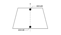
- FIG. It is a top view which shows one Embodiment of the windshield which concerns on this invention. It is sectional drawing of FIG. It is sectional drawing of a laminated glass. It is a schematic plan view which shows the measurement position of the thickness of a laminated glass. It is an example of the image used for the measurement of an intermediate film. It is a block diagram of the vehicle-mounted system arrange
- FIG. 1 is a plan view of the windshield
- FIG. 2 is a cross-sectional view of FIG.
- the vertical direction in FIG. 1 is referred to as “up and down”, “vertical”, and “vertical”, and the horizontal direction in FIG. 1 is referred to as “left and right”.
- FIG. 1 illustrates a windshield viewed from the inside of the vehicle. That is, the back side of the sheet of FIG. 1 is the outside of the vehicle, and the front side of the sheet of FIG. 1 is the inside of the vehicle.
- the windshield is provided with a substantially rectangular laminated glass 10 and is installed on the vehicle body in an inclined state.
- the inner surface 130 of the laminated glass 10 facing the vehicle interior is provided with a mask layer 110 that shields the field of view from the outside of the vehicle, and the photographing device 2 is arranged so as not to be seen from the outside of the vehicle by the mask layer 110.
- the photographing device 2 is a camera for photographing a situation outside the vehicle. Therefore, the mask layer 110 is provided with a photographing window 113 at a position corresponding to the photographing device 2, and the photographing device 2 disposed inside the vehicle through the photographing window 113 captures information on the situation outside the vehicle. Can be obtained. Further, an antifogging sheet 7 is attached to the photographing window 113.
- the information processing device 3 is connected to the photographing device 2, and information such as a photographed image acquired by the photographing device 2 is processed by the information processing device 3.
- the imaging device 2 and the information processing device 3 constitute an in-vehicle system 5, and the in-vehicle system 5 can provide various information to the passenger according to the processing of the information processing device 3.
- each component will be described.
- FIG. 3 is a sectional view of the laminated glass.
- the laminated glass 10 includes an outer glass plate 11 and an inner glass plate 12, and a resin intermediate film 13 is disposed between the glass plates 11 and 12.
- a resin intermediate film 13 is disposed between the glass plates 11 and 12.
- the outer glass plate 11 and the inner glass plate 12 will be described.
- known glass plates can be used, and they can be formed of heat ray absorbing glass, general clear glass, green glass, or UV green glass.
- these glass plates 11 and 12 need to realize visible light transmittance in accordance with the safety standards of the country where the automobile is used. For example, the required solar radiation absorption rate can be ensured by the outer glass plate 11, and the visible light transmittance can be adjusted by the inner glass plate 12 so as to satisfy safety standards. Examples of clear glass, green glass, heat ray absorbing glass, ultraviolet absorbing glass, and soda lime glass are shown below.
- the thickness of the laminated glass according to the present embodiment is not particularly limited, the total thickness of the outer glass plate 11 and the inner glass plate 12 can be set to 2.1 to 6 mm as an example, from the viewpoint of weight reduction.
- the total thickness is preferably 2.4 to 3.8 mm, more preferably 2.6 to 3.4 mm, and particularly preferably 2.7 to 3.2 mm.
- the thickness of each glass plate is not particularly limited,
- the thickness of the outer glass plate 11 and the inner glass plate 12 can be determined as follows.
- the outer glass plate 11 mainly needs durability and impact resistance against external obstacles. For example, when this laminated glass is used as a windshield of an automobile, the outer glass plate 11 has impact resistance performance against flying objects such as pebbles. is necessary. On the other hand, as the thickness is larger, the weight increases, which is not preferable. In this respect, the thickness of the outer glass plate 11 is preferably 1.8 to 2.3 mm, and more preferably 1.9 to 2.1 mm. Which thickness is adopted can be determined according to the application of the glass.
- the thickness of the inner glass plate 12 can be made equal to that of the outer glass plate 11, but for example, the thickness can be made smaller than that of the outer glass plate 11 in order to reduce the weight of the laminated glass. Specifically, considering the strength of the glass, it is preferably 0.6 to 2.0 mm, more preferably 0.8 to 1.6 mm, and particularly preferably 1.0 to 1.4 mm. preferable. Further, it is preferably 0.8 to 1.3 mm. Which thickness is used for the inner glass plate 12 can be determined according to the purpose of the glass.
- the measuring instrument is not particularly limited, and for example, a thickness gauge such as SM-112 manufactured by Teclock Co., Ltd. can be used.
- SM-112 manufactured by Teclock Co., Ltd.
- Teclock Co., Ltd. Teclock Co., Ltd.
- it is arranged so that the curved surface of the glass plate is placed on a flat surface, and the end of the glass plate is sandwiched by the thickness gauge and measured. Even when the glass plate is flat, it can be measured in the same manner as when the glass plate is curved.
- the intermediate film 13 is formed of at least one layer.
- the intermediate film 13 can be configured by three layers in which a soft core layer 131 is sandwiched between harder outer layers 132.
- it is not limited to this configuration, and may be formed of a plurality of layers including the core layer 131 and at least one outer layer 132 disposed on the outer glass plate 11 side.
- the intermediate film 13 may be disposed, or the intermediate film 13 may be configured such that the odd outer layer 132 is disposed on one side and the even outer layer 132 is disposed on the other side with the core layer 131 interposed therebetween.
- the outer layer 132 is provided on the outer glass plate 11 side as described above, but this is to improve the resistance to breakage against an external force from outside the vehicle or outside. Further, when the number of outer layers 132 is large, the sound insulation performance is also enhanced.
- the hardness thereof is not particularly limited.
- the material which comprises each layer 131,132 is not specifically limited, For example, a material can be selected on the basis of a Young's modulus. Specifically, it is preferably 1 to 20 MPa, more preferably 1 to 18 MPa, and particularly preferably 1 to 14 MPa at a frequency of 100 Hz and a temperature of 20 degrees. With such a range, it is possible to prevent the STL from decreasing in a low frequency range of approximately 3500 Hz or less.
- the Young's modulus of the outer layer 132 is preferably large in order to improve sound insulation performance in a high frequency region, as will be described later, and is 560 MPa or more, 600 MPa or more, 650 MPa or more, 700 MPa or more at a frequency of 100 Hz and a temperature of 20 degrees. It can be set to 750 MPa or more, 880 MPa or more, or 1300 MPa or more.
- the upper limit of the Young's modulus of the outer layer 132 is not particularly limited, but can be set from the viewpoint of workability, for example. For example, it is empirically known that when it becomes 1750 MPa or more, workability, particularly cutting becomes difficult.
- the outer layer 132 can be made of, for example, polyvinyl butyral resin (PVB).
- PVB polyvinyl butyral resin
- the core layer 131 can be made of, for example, an ethylene vinyl acetate resin (EVA) or a polyvinyl acetal resin that is softer than the polyvinyl butyral resin constituting the outer layer.
- the hardness of the polyvinyl acetal resin is controlled by (a) the degree of polymerization of the starting polyvinyl alcohol, (b) the degree of acetalization, (c) the type of plasticizer, (d) the addition ratio of the plasticizer, etc. Can do. Therefore, by appropriately adjusting at least one selected from these conditions, a hard polyvinyl butyral resin used for the outer layer 132 and a soft polyvinyl butyral resin used for the core layer 131 even if the same polyvinyl butyral resin is used. Can be made separately.
- the hardness of the polyvinyl acetal resin can also be controlled by the type of aldehyde used for acetalization, coacetalization with a plurality of aldehydes, or pure acetalization with a single aldehyde. Although it cannot generally be said, the polyvinyl acetal resin obtained by using an aldehyde having a large number of carbon atoms tends to be softer.
- the core layer 131 has an aldehyde having 5 or more carbon atoms (for example, n-hexylaldehyde, 2-ethylbutyraldehyde, n-heptylaldehyde, n-octylaldehyde) and a polyvinyl acetal resin obtained by acetalization with polyvinyl alcohol can be used.
- a predetermined Young's modulus it is not limited to the said resin.
- the total thickness of the intermediate film 13 is not particularly limited, but is preferably 0.3 to 6.0 mm, more preferably 0.5 to 4.0 mm, and 0.6 to 2.0 mm. It is particularly preferred.
- the thickness of the core layer 131 is preferably 0.1 to 2.0 mm, and more preferably 0.1 to 0.6 mm.
- the thickness of each outer layer 132 is preferably 0.1 to 2.0 mm, and more preferably 0.1 to 1.0 mm.
- the total thickness of the intermediate film 13 can be made constant, and the thickness of the core layer 131 can be adjusted therein.
- the thickness of the core layer 131 and the outer layer 132 can be measured as follows, for example. First, the cross section of the laminated glass is enlarged and displayed by 175 times using a microscope (for example, VH-5500 manufactured by Keyence Corporation). And the thickness of the core layer 131 and the outer layer 132 is specified visually, and this is measured. At this time, in order to eliminate visual variation, the number of measurements is set to 5 times, and the average value is defined as the thickness of the core layer 131 and the outer layer 132. For example, an enlarged photograph of a laminated glass as shown in FIG. 7 is taken, and the core layer and the outer layer 132 are specified in this and the thickness is measured.
- the thickness of the core layer 131 and the outer layer 132 of the intermediate film 13 does not need to be constant over the entire surface, and can be a wedge shape for laminated glass used for a head-up display, for example.
- the thickness of the core layer 131 and the outer layer 132 of the intermediate film 13 is measured at the position where the thickness is the smallest, that is, the lowermost side portion of the laminated glass.
- the intermediate film 13 is wedge-shaped, the outer glass plate and the inner glass plate are not arranged in parallel, but such arrangement is also included in the glass plate in the present invention.
- the present invention includes, for example, the arrangement of the outer glass plate and the inner glass plate when the intermediate film 13 using the core layer 131 or the outer layer 132 whose thickness is increased at a rate of change of 3 mm or less per meter is used. .
- the method for producing the intermediate film 13 is not particularly limited.
- the resin component such as the polyvinyl acetal resin described above, a plasticizer, and other additives as necessary are blended and kneaded uniformly, and then each layer is collectively And a method of laminating two or more resin films prepared by this method by a pressing method, a laminating method or the like.
- the resin film before lamination used in a method of laminating by a press method, a laminating method or the like may have a single layer structure or a multilayer structure.
- the intermediate film 13 can be formed of a single layer in addition to the above-described plural layers.
- the windshield according to the present embodiment captures the outside of the vehicle by the information acquisition device, the windshield needs to have a visible light transmittance to such an extent that the situation outside the vehicle can be captured. Accordingly, the visible light transmittance is configured to be 70% or more.
- permeability can be measured by the spectroscopic measurement method prescribed
- the ultraviolet transmittance as a laminated glass is as follows. Tuv380 ⁇ 0.5% and Tuv400 ⁇ 3.5% (1)
- Tuv380 is the ultraviolet transmittance defined in ISO9050: 1990
- Tuv400 is the ultraviolet transmittance defined in ISO13837: 2008 convention A.
- the ultraviolet transmittance can be measured with a known spectrophotometer, for example, “UV-3100PC” (manufactured by Shimadzu Corporation).
- Tuv400 in the above formula (1) is preferably 2.5% or less, more preferably 2.0% or less, and particularly preferably 1.0% or less.
- the laminated glass of the present invention is constituted including the following constitutions (1) to (3).
- the laminated glass is formed of green glass, heat ray absorbing glass, or ultraviolet absorbing glass.
- the laminated glass using these satisfies the above formula (1) as described later.
- a film having ultraviolet shielding properties is provided on at least one of the inner side surface of the inner glass plate and the inner side surface of the inner glass plate and the antifogging sheet.
- Examples of the film having an ultraviolet shielding property include an organic-inorganic composite film containing an ultraviolet absorber and a light-resistant film.
- the organic-inorganic composite film may be, for example, a film containing a hydrolysis-condensation product of tetrafunctional silicon alkoxide, a hydrolysis-condensation product of trifunctional silicon alkoxide, an ultraviolet absorber that is an organic material, and an organic polymer. it can.
- the light-resistant film is, for example, a polyester film that can contain 0.05 to 30% by mass of an ultraviolet absorber.
- An ultraviolet absorbing performance is imparted to the intermediate film.
- an intermediate film having a long wavelength ultraviolet absorption function can be used.
- an intermediate film containing an ultraviolet absorber (for example, one containing more than usual) or an intermediate film containing a specific light absorber can be used.
- the light absorber for example, one having an anthraquinone structure having a thiophenyl group can be employed. Thereby, the ultraviolet transmittance can be reduced without reducing the visible light transmittance.
- the light absorber having such an anthraquinone structure may have at least one or more thiophenyl groups, and preferably has two or more thiophenyl groups.
- the lower limit of the content of the light absorber having an anthraquinone structure with respect to the intermediate film is, for example, 0.003 parts by weight with respect to 100 parts by weight of the thermoplastic resin, and the upper limit is, for example, 0.007 parts by weight. it can.
- interposed the intermediate film containing such a light absorber about 0.0035 weight part with clear glass can make Tuv380 0% and Tuv400 about 2.8%.
- the ultraviolet transmittance can be further reduced.
- the mask layer 110 is laminated on the inner surface 130 (the inner surface of the inner glass plate 12) 130 of the laminated glass 10, and on the peripheral edge of the laminated glass 10. Are formed along.
- the mask layer 110 according to the present embodiment protrudes in a rectangular shape downward from the peripheral region 111 along the peripheral portion of the laminated glass 10 and the upper side portion of the laminated glass 10.
- the protruding region 112 can be divided.
- the peripheral region 111 shields light incident from the peripheral portion of the windshield 1.
- the protruding region 112 prevents the photographing device 2 disposed in the vehicle from being seen from outside the vehicle.
- a rectangular information acquisition region (opening) 113 is provided at a position corresponding to the photographing device 2 in the protruding region 112 of the mask layer 110 so that the photographing device 2 can be in a situation outside the vehicle. It has been. That is, the imaging window 113 is provided independently from the non-shielding region 120 on the inner side in the plane direction from the mask layer 110. Further, the photographing window 113 is a region where the material of the mask layer 110 is not laminated, and the laminated glass has the above-described visible light transmittance, so that the situation outside the vehicle can be photographed.
- the mask layer 110 can be laminated on the inner surface of the outer glass plate 11 and the outer surface of the inner glass plate 12, for example, in addition to the inner layer of the inner glass plate 12 as described above. Moreover, it can also laminate
- the material of the mask layer 110 may be appropriately selected according to the embodiment as long as the field of view from the outside of the vehicle can be blocked.
- a dark ceramic such as black, brown, gray, or dark blue is used. Also good.
- black ceramic is selected as the material of the mask layer 110
- black ceramic is laminated on the peripheral portion on the inner surface 130 of the inner glass plate 12 by screen printing or the like, and the ceramic laminated with the inner glass plate 12 is heated. To do. Thereby, the mask layer 110 can be formed on the peripheral edge of the inner glass plate 12. Moreover, when printing black ceramic, the area
- various materials can be used for the ceramic used for the mask layer 110. For example, a ceramic having the composition shown in Table 1 below can be used for the mask layer 110.
- Main component Copper oxide, Chromium oxide, Iron oxide and Manganese oxide * 2
- Main component Bismuth borosilicate, Zinc borosilicate
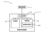
- FIG. 6 illustrates the configuration of the in-vehicle system 5.
- the in-vehicle system 5 according to the present embodiment includes the imaging device 2 and an image processing device 3 connected to the imaging device 2.
- the image processing device 3 is a device that processes the captured image acquired by the imaging device 2.
- the image processing apparatus 3 includes, for example, general hardware such as a storage unit 31, a control unit 32, and an input / output unit 33 connected by a bus as a hardware configuration.
- general hardware such as a storage unit 31, a control unit 32, and an input / output unit 33 connected by a bus as a hardware configuration.
- the hardware configuration of the image processing apparatus 3 does not have to be limited to such an example, and the specific hardware configuration of the image processing apparatus 3 is appropriately added or omitted according to the embodiment. And additions are possible.
- the storage unit 31 stores various data and programs used in processing executed by the control unit 32 (not shown).
- the storage unit 31 may be realized, for example, by a hard disk or a recording medium such as a USB memory.
- the various data and programs stored in the storage unit 31 may be acquired from a recording medium such as a CD (Compact Disc) or a DVD (Digital Versatile Disc).
- the storage unit 31 may be referred to as an auxiliary storage device.
- the laminated glass 10 is disposed in an inclined posture with respect to the vertical direction and is curved.
- the imaging device 2 images the situation outside the vehicle through such a laminated glass 10. Therefore, the captured image acquired by the imaging device 2 is deformed according to the posture, shape, refractive index, optical defect, and the like of the laminated glass 10.
- the storage unit 31 may store correction data for correcting the image deformed due to the aberration of the laminated glass 10 and the camera lens.
- the control unit 32 includes one or more processors such as a microprocessor or a CPU (Central Processing Unit), and peripheral circuits (ROM (Read Only Memory), RAM (Random Access Memory), an interface circuit) used for processing of the processor. Etc.). ROM, RAM, and the like may be referred to as a main storage device in the sense that they are arranged in an address space handled by the processor in the control unit 32.
- the control unit 32 functions as the image processing unit 321 by executing various data and programs stored in the storage unit 31.
- the image processing unit 321 processes the captured image acquired by the imaging device 2.
- the processing of the captured image can be selected as appropriate according to the embodiment.
- the image processing unit 321 may recognize the subject appearing in the captured image by analyzing the captured image by pattern matching or the like.
- the image processing unit 321 since the imaging device 2 captures a situation in front of the vehicle, the image processing unit 321 further determines whether or not a living organism such as a human is captured in front of the vehicle based on the subject recognition. Also good.
- the image processing unit 321 may output a warning message by a predetermined method. Further, for example, the image processing unit 321 may perform a predetermined processing on the captured image. Then, the image processing unit 321 may output the processed photographed image to a display device (not shown) such as a display connected to the image processing device 3.
- the input / output unit 33 is one or a plurality of interfaces for transmitting / receiving data to / from an apparatus existing outside the image processing apparatus 3.
- the input / output unit 33 is, for example, an interface for connecting to a user interface or an interface such as USB (Universal Serial Bus).
- the image processing apparatus 3 is connected to the photographing apparatus 2 via the input / output unit 33 and acquires a photographed image photographed by the photographing apparatus 2.
- Such an image processing device 3 may be a general-purpose device such as a PC (Personal Computer) or a tablet terminal in addition to a device designed exclusively for the service to be provided.
- PC Personal Computer
- tablet terminal in addition to a device designed exclusively for the service to be provided.
- the information acquisition device is attached to a bracket (not shown), and this bracket is attached to the mask layer. Therefore, in this state, the attachment of the information acquisition device to the bracket and the attachment of the bracket to the mask layer are adjusted so that the optical axis of the camera of the information acquisition device passes through the information acquisition region.
- a cover (not shown) is attached to the bracket so as to cover the photographing apparatus 2. Therefore, the photographing device 2 is arranged in a space surrounded by the laminated glass 10, the bracket, and the cover so that it cannot be seen from the inside of the vehicle and only a part of the photographing device 2 can be seen from the outside of the vehicle through the photographing window 113. There is no such thing.
- the photographing apparatus 2 and the above-described input / output unit 33 are connected by a cable (not shown). The cable is pulled out from the cover and connected to the image processing apparatus 3 arranged at a predetermined position in the vehicle. .
- the antifogging sheet As described above, the antifogging sheet is affixed to the information acquisition area, and as shown in FIG. 7, the adhesive layer 71, the base film 72, and the antifogging layer 73 are laminated in this order. It is. Further, the first protective sheet 74 that can be peeled off is attached to the adhesive layer 71 and the second protective sheet 75 that can be peeled off is attached to the anti-fogging layer 73 until they are fixed to the information acquisition area.
- the anti-fogging laminated body is comprised by.
- the antifogging sheet 7 is formed in a shape corresponding to the photographing window 113, but can be formed in a shape slightly smaller than the photographing window 113, for example. Alternatively, it may be formed so as to be larger than the photographing window 113 and to cover a part of the mask layer 110 beyond the photographing window 113.
- each layer will be described.
- the anti-fogging layer is not particularly limited as long as the anti-fogging effect of the laminated glass plate 10 is exhibited, and a known one can be used.
- the antifogging layer has a hydrophilic type in which water generated from water vapor is formed on the surface as a water film, a water absorption type that absorbs water vapor, a water-repellent water absorption type in which water droplets are less likely to condense on the surface, and water droplets generated from water vapor.
- a water-repellent type that waters
- any type of anti-fogging layer is applicable. Below, the example of the water-repellent water absorption type anti-fogging layer is demonstrated as the example.
- the organic-inorganic composite antifogging layer is a single layer film formed on the surface of the base film or a multilayer film laminated.
- the organic-inorganic composite antifogging layer contains at least a water absorbent resin, a water repellent group, and a metal oxide component.
- the antifogging film may further contain other functional components as necessary.
- the type of water-absorbing resin is not limited as long as it can absorb and retain water.
- the water repellent group can be supplied to the antifogging film from a metal compound having a water repellent group (water repellent group-containing metal compound).
- the metal oxide component can be supplied to the antifogging film from a water repellent group-containing metal compound, other metal compounds, metal oxide fine particles and the like.
- each component will be described.
- Water absorbent resin there is no particular limitation as the water absorbent resin, polyethylene glycol, polyether resin, polyurethane resin, starch resin, cellulose resin, acrylic resin, epoxy resin, polyester polyol, hydroxyalkyl cellulose, polyvinyl alcohol, polyvinyl pyrrolidone, A polyvinyl acetal resin, polyvinyl acetate, etc. are mentioned. Among these, preferred are hydroxyalkyl cellulose, polyvinyl alcohol, polyvinyl pyrrolidone, polyvinyl acetal resin, polyvinyl acetate, epoxy resin and polyurethane resin, and more preferred are polyvinyl acetal resin, epoxy resin and polyurethane resin. Among them, polyvinyl acetal resin is particularly preferable.
- the polyvinyl acetal resin can be obtained by subjecting polyvinyl alcohol to an acetalization by a condensation reaction of aldehyde with polyvinyl alcohol.
- the acetalization of polyvinyl alcohol may be carried out using a known method such as a precipitation method using an aqueous medium in the presence of an acid catalyst, or a dissolution method using a solvent such as alcohol.
- Acetalization can also be carried out in parallel with saponification of polyvinyl acetate.
- the degree of acetalization is preferably 2 to 40 mol%, more preferably 3 to 30 mol%, particularly 5 to 20 mol%, and in some cases 5 to 15 mol%.
- the degree of acetalization can be measured based on, for example, 13 C nuclear magnetic resonance spectroscopy.
- a polyvinyl acetal resin having an acetalization degree in the above range is suitable for forming an organic-inorganic composite antifogging layer having good water absorption and water resistance.
- the average degree of polymerization of polyvinyl alcohol is preferably 200 to 4500, more preferably 500 to 4500.
- a high average degree of polymerization is advantageous for the formation of an organic-inorganic composite antifogging layer having good water absorption and water resistance, but if the average degree of polymerization is too high, the viscosity of the solution becomes too high, which hinders film formation. I have come.
- the saponification degree of polyvinyl alcohol is preferably 75 to 99.8 mol%.
- aldehyde to be subjected to a condensation reaction with polyvinyl alcohol examples include aliphatic aldehydes such as formaldehyde, acetaldehyde, butyraldehyde, hexyl carbaldehyde, octyl carbaldehyde, decyl carbaldehyde.
- benzaldehyde 2-methylbenzaldehyde, 3-methylbenzaldehyde, 4-methylbenzaldehyde, other alkyl group-substituted benzaldehydes; chlorobenzaldehyde, other halogen atom-substituted benzaldehydes; alkyl such as hydroxy group, alkoxy group, amino group, cyano group
- aromatic aldehydes such as condensed aromatic aldehydes such as naphthaldehyde and anthraldehyde.
- Aromatic aldehydes having strong hydrophobicity are advantageous in forming an organic-inorganic composite antifogging layer having a low degree of acetalization and excellent water resistance.
- the use of an aromatic aldehyde is also advantageous in forming a film having high water absorption while leaving many hydroxyl groups remaining.
- the polyvinyl acetal resin preferably contains an acetal structure derived from an aromatic aldehyde, particularly benzaldehyde.
- epoxy resin examples include glycidyl ether epoxy resin, glycidyl ester epoxy resin, glycidyl amine epoxy resin, and cyclic aliphatic epoxy resin. Of these, cycloaliphatic epoxy resins are preferred.
- polyurethane resin examples include a polyurethane resin composed of a polyisocyanate and a polyol.
- a polyurethane resin composed of a polyisocyanate and a polyol.
- the polyol an acrylic polyol and a polyoxyalkylene polyol are preferable.
- the organic / inorganic composite antifogging layer is mainly composed of a water-absorbing resin.
- the “main component” means a component having the highest content on a mass basis.
- the content of the water absorbent resin based on the weight of the organic / inorganic composite antifogging layer is preferably 50% by weight or more, more preferably 60% by weight or more, and particularly preferably 65% from the viewpoint of film hardness, water absorption and antifogging property. It is 95% by weight or less, more preferably 90% by weight or less, and particularly preferably 85% by weight or less.
- water repellent group In order to sufficiently obtain the above-described effects due to the water repellent group, it is preferable to use a water repellent group having high water repellency.
- Preferred water repellent groups are (1) a chain or cyclic alkyl group having 3 to 30 carbon atoms, and (2) a chain or cyclic group having 1 to 30 carbon atoms in which at least a part of hydrogen atoms are substituted with fluorine atoms. It is at least one selected from alkyl groups (hereinafter sometimes referred to as “fluorine-substituted alkyl groups”).
- the chain or cyclic alkyl group is preferably a chain alkyl group.
- the chain alkyl group may be a branched alkyl group, but is preferably a linear alkyl group.
- An alkyl group having more than 30 carbon atoms may cause the antifogging film to become cloudy.
- the carbon number of the alkyl group is preferably 20 or less, more preferably 6 to 14.
- alkyl groups are linear alkyl groups having 6 to 14 carbon atoms, particularly 6 to 12 carbon atoms, such as n-hexyl group (6 carbon atoms), n-decyl group (10 carbon atoms), n-dodecyl group ( 12).
- the fluorine-substituted alkyl group may be a group in which only part of the hydrogen atoms of the chain or cyclic alkyl group is substituted with fluorine atoms, and all of the hydrogen atoms of the chain or cyclic alkyl group. May be a group substituted with a fluorine atom, for example, a linear perfluoroalkyl group.
- the fluorine-substituted alkyl group has high water repellency, a sufficient effect can be obtained by adding a small amount. However, if the content of the fluorine-substituted alkyl group is too large, it may be separated from other components in the coating solution for forming a film.
- a metal compound having a water repellent group water repellent group-containing metal compound
- a metal compound having a water repellent group and a hydrolyzable functional group or a halogen atom A water repellent group-containing hydrolyzable metal compound) or a hydrolyzate thereof may be added to a coating solution for forming a film.
- the water repellent group may be derived from a water repellent group-containing hydrolyzable metal compound.
- the water repellent group-containing hydrolyzable metal compound is preferably a water repellent group-containing hydrolyzable silicon compound represented by the following formula (I).
- R is a water repellent group, that is, a linear or cyclic alkyl group having 1 to 30 carbon atoms in which at least part of hydrogen atoms may be substituted with fluorine atoms
- Y is a hydrolyzable functional group.
- a group or a halogen atom, and m is an integer of 1 to 3.
- the hydrolyzable functional group is, for example, at least one selected from an alkoxyl group, an acetoxy group, an alkenyloxy group, and an amino group, preferably an alkoxy group, particularly an alkoxy group having 1 to 4 carbon atoms.
- An alkenyloxy group is, for example, an isopropenoxy group.
- the halogen atom is preferably chlorine.
- the functional groups exemplified here can also be used as “hydrolyzable functional groups” described below.
- m is preferably 1 to 2.
- the compound represented by formula (I) supplies the component represented by the following formula (II) when hydrolysis and polycondensation have completely proceeded.
- R and m are as described above.
- the compound represented by formula (II) actually forms a network structure in which silicon atoms are bonded to each other through oxygen atoms in the antifogging film.
- the compound represented by the formula (I) is hydrolyzed or partially hydrolyzed, and further, at least partly polycondensed to alternately connect silicon atoms and oxygen atoms, and three-dimensionally.
- a network structure of spreading siloxane bonds Si—O—Si
- a water repellent group R is connected to silicon atoms included in the network structure.
- the water repellent group R is fixed to the network structure of the siloxane bond through the bond R—Si. This structure is advantageous in uniformly dispersing the water repellent group R in the film.
- the network structure may contain a silica component supplied from a silicon compound (for example, tetraalkoxysilane, silane coupling agent) other than the water repellent group-containing hydrolyzable silicon compound represented by the formula (I).
- a silica component supplied from a silicon compound for example, tetraalkoxysilane, silane coupling agent
- a hydrolyzable silicon compound having no water repellent group and a hydrolyzable functional group or halogen atom water repellent group-free hydrolyzable silicon compound
- a network structure of siloxane bonds including silicon atoms bonded to water repellent groups and silicon atoms not bonded to water repellent groups can be formed. With such a structure, it becomes easy to adjust the water repellent group content and the metal oxide component content in the antifogging film independently of each other.
- the water repellent group has an effect of improving the antifogging performance by improving the water vapor permeability on the surface of the antifogging film containing the water-absorbing resin. Since the two functions of water absorption and water repellency are contradictory to each other, the water-absorbing material and the water-repellent material have been conventionally assigned to different layers, but the water-repellent group is located near the surface of the antifogging layer. Eliminates the uneven distribution of water, prolongs the time until condensation, and improves the antifogging property of the antifogging film having a single layer structure. The effect will be described below.
- Water vapor that has entered the anti-fogging film containing the water-absorbing resin is hydrogen-bonded with a hydroxyl group of the water-absorbing resin or the like, and is retained in the form of bound water. As the amount increases, the water vapor is retained from the bound water form to the semi-bound water form and finally to the free water form retained in the voids in the antifogging membrane.
- the water repellent group prevents the formation of hydrogen bonds and facilitates the dissociation of the formed hydrogen bonds. If the content of the water-absorbing resin is the same, there is no difference in the number of hydroxyl groups capable of hydrogen bonding in the film, but the water-repellent group reduces the rate of hydrogen bond formation.
- the anti-fogging film containing a water repellent group moisture is finally retained in the film in any of the above forms, but by the time it is retained, it remains as water vapor up to the bottom of the film. Can diffuse. Also, the water once retained is easily dissociated and easily moves to the bottom of the membrane in the state of water vapor. As a result, the distribution of moisture retention in the film thickness direction is relatively uniform from the vicinity of the surface to the bottom of the film. That is, since all of the thickness direction of the anti-fogging film can be effectively utilized and water supplied to the film surface can be absorbed, water droplets hardly condense on the surface and the anti-fogging property is improved.
- the anti-fogging film that has absorbed moisture has a feature that it is difficult to freeze even at low temperatures because water droplets are less likely to condense on the surface. Therefore, when this anti-fogging film is fixed to the information acquisition region, the field of view of the information acquisition region can be secured in a wide temperature range.
- a water-repellent group is introduced into an antifogging film using a water-repellent group-containing hydrolyzable silicon compound (see formula (I))
- a strong siloxane bond (Si—O—Si) network structure is formed.
- the formation of this network structure is advantageous not only from the viewpoint of wear resistance but also from the viewpoint of improving hardness, water resistance and the like.
- the water repellent group may be added to such an extent that the contact angle of water on the surface of the antifogging film is 70 degrees or more, preferably 80 degrees or more, more preferably 90 degrees or more.
- the contact angle of water a value measured by dropping a 4 mg water droplet on the surface of the membrane is adopted.
- a methyl group or an ethyl group having a slightly weak water repellency is used as the water repellent group, it is preferable to add an amount of the water repellent group having a water contact angle in the above range to the antifogging film.
- the upper limit of the contact angle of the water droplet is not particularly limited, but is, for example, 150 degrees or less, for example, 120 degrees or less, and further 100 degrees or less. It is preferable that the water repellent group be uniformly contained in the antifogging film so that the contact angle of the water droplets is in the above range in all regions of the surface of the antifogging film.
- the anti-fogging film is 0.05 parts by mass or more, preferably 0.1 parts by mass or more, more preferably 0.3 parts by mass or more with respect to 100 parts by mass of the water absorbent resin. It is preferable that a water repellent group is contained so that it may become in the range of 5 parts by mass or less, preferably 5 parts by mass or less.
- the inorganic oxide is, for example, an oxide of at least one element selected from Si, Ti, Zr, Ta, Nb, Nd, La, Ce, and Sn, and includes at least an Si oxide (silica).
- the organic / inorganic composite antifogging layer is preferably 0.01 parts by weight or more, more preferably 0.1 parts by weight or more, still more preferably 0.2 parts by weight or more, particularly preferably 100 parts by weight of the water-absorbing resin.
- the inorganic oxide is a component necessary for ensuring the strength of the organic-inorganic composite antifogging layer, particularly the abrasion resistance. However, when the content of the inorganic oxide increases, the antifogging property of the organic-inorganic composite antifogging layer decreases. .
- the organic-inorganic composite antifogging layer may further contain inorganic oxide fine particles as at least a part of the inorganic oxide.
- the inorganic oxide constituting the inorganic oxide fine particles is, for example, an oxide of at least one element selected from Si, Ti, Zr, Ta, Nb, Nd, La, Ce and Sn, preferably silica fine particles. is there.
- the silica fine particles can be introduced into the organic-inorganic composite antifogging layer by adding, for example, colloidal silica.
- the inorganic oxide fine particles are excellent in the action of transmitting the stress applied to the organic-inorganic composite antifogging layer to the article supporting the organic-inorganic composite antifogging layer, and have high hardness. Therefore, the addition of inorganic oxide fine particles is advantageous from the viewpoint of improving the wear resistance of the organic-inorganic composite antifogging layer.
- inorganic oxide fine particles when inorganic oxide fine particles are added to the organic-inorganic composite antifogging layer, fine voids are formed at sites where the fine particles are in contact with or close to, and water vapor is easily taken into the film from the voids. For this reason, the addition of inorganic oxide fine particles may sometimes have an advantageous effect on improving the antifogging property.
- the inorganic oxide fine particles can be supplied to the organic / inorganic composite antifogging layer by adding the inorganic oxide fine particles formed in advance to the coating liquid for forming the organic / inorganic composite antifogging layer.
- the average particle size of the inorganic oxide fine particles is preferably 1 to 20 nm, and more preferably 5 to 20 nm.
- the average particle diameter of the inorganic oxide fine particles is described in the state of primary particles. The average particle size of the inorganic oxide fine particles is determined by measuring the particle sizes of 50 fine particles arbitrarily selected by observation using a scanning electron microscope and adopting the average value.
- the inorganic oxide fine particles are preferably 0 to 50 parts by weight, more preferably 2 to 30 parts by weight, still more preferably 5 to 25 parts by weight, and particularly preferably 10 to 20 parts by weight with respect to 100 parts by weight of the water absorbent resin. It is good to add so that it may become a part.
- the anti-fogging film may contain a metal oxide component derived from a hydrolyzable metal compound having no water-repellent group (water-repellent group-free hydrolyzable compound).
- a preferred hydrolyzable metal compound containing no water repellent group is a hydrolyzable silicon compound having no water repellent group.
- the hydrolyzable silicon compound having no water repellent group is, for example, at least one silicon compound selected from silicon alkoxide, chlorosilane, acetoxysilane, alkenyloxysilane and aminosilane (however, having no water repellent group), Silicon alkoxide having no water repellent group is preferred.
- An example of alkenyloxysilane is isopropenoxysilane.
- the hydrolyzable silicon compound having no water repellent group may be a compound represented by the following formula (III). SiY4 (III)
- Y is a hydrolyzable functional group, preferably at least one selected from an alkoxyl group, an acetoxy group, an alkenyloxy group, an amino group, and a halogen atom.
- the water repellent group-free hydrolyzable metal compound is hydrolyzed or partially hydrolyzed, and further, at least a part thereof is polycondensed to supply a metal oxide component in which a metal atom and an oxygen atom are bonded.
- This component can strongly bond the metal oxide fine particles and the water-absorbent resin, and can contribute to improvement of the wear resistance, hardness, water resistance, etc. of the antifogging film.
- the metal oxide component derived from the hydrolyzable metal compound having no water repellent group is 0 to 40 parts by mass, preferably 0.1 to 30 parts by mass, more preferably 1 to 1 part by mass with respect to 100 parts by mass of the water absorbent resin. It may be 20 parts by mass, particularly preferably 3 to 10 parts by mass, and in some cases 4 to 12 parts by mass.
- a preferred example of the hydrolyzable silicon compound having no water repellent group is tetraalkoxysilane, more specifically, tetraalkoxysilane having an alkoxy group having 1 to 4 carbon atoms.
- Tetraalkoxysilanes include, for example, tetramethoxysilane, tetraethoxysilane, tetra-n-propoxysilane, tetraisopropoxysilane, tetra-n-butoxysilane, tetraisobutoxysilane, tetra-sec-butoxysilane, and tetra-tert- It is at least one selected from butoxysilane.
- the metal oxide component derived from tetraalkoxysilane may be added in the range of 0 to 30 parts by mass, preferably 1 to 20 parts by mass, more preferably 3 to 10 parts by mass with respect to 100 parts by mass of the water absorbent resin.
- silane coupling agents are silicon compounds having different reactive functional groups. A part of the reactive functional group is preferably a hydrolyzable functional group.
- the silane coupling agent is, for example, a silicon compound having an epoxy group and / or an amino group and a hydrolyzable functional group.
- preferable silane coupling agents include glycidyloxyalkyltrialkoxysilane and aminoalkyltrialkoxysilane. In these silane coupling agents, the number of carbon atoms of the alkylene group directly bonded to the silicon atom is preferably 1 to 3.
- the glycidyloxyalkyl group and the aminoalkyl group include a functional group (epoxy group or amino group) that exhibits hydrophilicity, the glycidyloxyalkyl group and the aminoalkyl group are not water-repellent as a whole although they include an alkylene group.
- the silane coupling agent strongly binds the water-absorbing resin that is an organic component and the metal oxide fine particles that are an inorganic component, and can contribute to the improvement of wear resistance, hardness, water resistance, and the like of the antifogging film.
- the metal oxide component derived from the silane coupling agent is in the range of 0 to 10 parts by weight, preferably 0.05 to 5 parts by weight, more preferably 0.1 to 2 parts by weight with respect to 100 parts by weight of the water absorbent resin. Should be added.
- the antifogging film may include a crosslinked structure derived from a crosslinking agent, preferably at least one crosslinking agent selected from an organic boron compound, an organic titanium compound, and an organic zirconium compound.
- a crosslinked structure improves the wear resistance, scratch resistance and water resistance of the antifogging film. From another viewpoint, the introduction of a crosslinked structure facilitates improving the durability of the antifogging film without deteriorating the antifogging performance.
- the antifogging film When a crosslinked structure derived from a crosslinking agent is introduced into the antifogging film in which the metal oxide component is a silica component, the antifogging film has a metal atom other than silicon as a metal atom, preferably boron, titanium or zirconium, May be contained.
- the type of the crosslinking agent is not particularly limited as long as it can crosslink the water-absorbing resin to be used.
- the organic titanium compound is, for example, at least one selected from titanium alkoxide, titanium chelate compound, and titanium acylate.
- the titanium alkoxide is, for example, titanium tetraisopropoxide, titanium tetra-n-butoxide, or titanium tetraoctoxide.
- the titanium chelate compound include titanium acetylacetonate, titanium ethylacetoacetate, titanium octylene glycol, titanium triethanolamine, and titanium lactate.
- the titanium lactate may be an ammonium salt (titanium lactate ammonium).
- the titanium acylate is, for example, titanium stearate.
- Preferred organic titanium compounds are titanium chelate compounds, particularly titanium lactate.
- a preferable cross-linking agent is an organic titanium compound, particularly titanium lactate.
- Additives may be surfactants, leveling agents, ultraviolet absorbers, colorants, antifoaming agents, preservatives, and the like.
- the silicon alkoxide preferably contains a silane coupling agent.
- light shielding for example, ultraviolet shielding
- the reason why the light shielding property of the organic-inorganic composite antifogging layer is improved by the silane coupling agent is that the light absorbing agent which is an organic compound is more uniformly dispersed in the water-absorbing resin containing silica by the addition of the silane coupling agent. It is thought that it is to become.
- ultraviolet absorbers examples include benzotriazole compounds [2- (2′-hydroxy-5′-methylphenyl) benzotriazole, 2- (2′-hydroxy-3 ′, 5′-di-t-butylphenyl)].
- Benzotriazole, etc. benzophenone compounds [2,2 ′, 4,4′-tetrahydroxybenzophenone, 2,4-dihydroxybenzophenone, 2-hydroxy-4-methoxybenzophenone, 2-hydroxy-4-octoxybenzophenone, 5, 5′-methylenebis (2-hydroxy-4-methoxybenzophenone) etc.]
- hydroxyphenyltriazine compound [2- (2-hydroxy-4-octoxyphenyl) -4,6-bis (2,4-di-t- Butylphenyl) -s-triazine, 2- (2-hydroxy-4-methoxyphenyl) Nyl) -4,6-diphenyl-s-triazine, 2- (2-hydroxy-4-propoxy-5-methylpheny
- An ultraviolet absorber may be used independently and may use 2 or more types together.
- the ultraviolet absorber may be at least one organic dye selected from a polymethine compound, an imidazoline compound, a coumarin compound, a naphthalimide compound, a perylene compound, an azo compound, an isoindolinone compound, a quinophthalone compound, and a quinoline compound.
- an ultraviolet absorber that is an organic substance is preferable, and more preferable is at least one selected from a benzotriazole compound, a benzophenone compound, a hydroxyphenyltriazine compound, and a cyanoacrylate compound, and more preferable. Is a benzophenone compound.
- a benzophenone compound is preferable because it has good solubility in an alcohol-based solvent contained in a coating solution for forming an organic-inorganic composite antifogging layer and is uniformly dispersed by a polyvinyl acetal resin.
- the ultraviolet absorber preferably has a hydroxyl group, and more preferably one having two or more hydroxyl groups bonded to one benzene skeleton of the ultraviolet absorber.
- the ultraviolet absorber is preferably added in an amount of 0.1 to 50 parts by weight, more preferably 1.0 to 40 parts by weight, and still more preferably 2 to 35 parts by weight with respect to 100 parts by weight of the water absorbent resin.
- infrared absorbers examples include polymethine compounds, cyanine compounds, phthalocyanine compounds, naphthalocyanine compounds, naphthoquinone compounds, anthraquinone compounds, dithiol compounds, immonium compounds, diimonium compounds, aminium compounds, pyrylium compounds, cerium compounds, squarylium compounds, and benzene.
- Organic infrared absorbers such as counterion conjugates of dithiol metal complex anions and cyanine dye cations; tungsten oxide, tin oxide, indium oxide, magnesium oxide, titanium oxide, chromium oxide, zirconium oxide, nickel oxide, aluminum oxide, oxidation Inorganic infrared absorption such as zinc, iron oxide, ammonium oxide, lead oxide, bismuth oxide, lanthanum oxide, tungsten oxide, indium tin oxide, antimony tin oxide , And the like.
- An infrared absorber may be used independently and may use 2 or more types together.
- inorganic infrared absorbers are preferable, and indium tin oxide and / or antimony tin oxide are more preferable. Indium tin oxide and / or antimony tin oxide are preferable because they have good stability in the coating solution for forming the organic-inorganic composite antifogging layer and are uniformly dispersed by the polyvinyl acetal resin.
- the infrared absorber is preferably added in an amount of 0.1 to 50 parts by weight, more preferably 1.0 to 40 parts by weight, and still more preferably 2 to 35 parts by weight with respect to 100 parts by weight of the water absorbent resin.
- the anti-fogging layer described above is a water-absorbing type mainly composed of a water-absorbing resin, but a hydrophilic type can also be employed.
- the hydrophilic type has a hydrophilic resin as a main component, and a known one, for example, an antifogging layer described in JP 2011-213555 A can be used. Specifically, it is as follows.
- the antifogging layer has a double chain type anionic interface having two carbon chains each having 6 or more carbon atoms as a main component and branched from the hydrophilic group.
- an activator and a polyol compound are included, and it is preferable that the silicon oxide includes silicon oxide fine particles and a silicon oxide component generated by a hydrolysis reaction and a condensation polymerization reaction of silicon alkoxide.
- the “closed hole” is a hole that is not open on the film surface.
- the “main component” means the most abundant component as usual, and specifically refers to a component occupying 50% by mass or more.
- the “polyol compound” is a polyhydric alcohol such as diol or triol.
- such a hydrophilic type antifogging layer is formed by applying a solution for forming an antifogging layer containing silicon alkoxide and silicon oxide fine particles to form a coating film, and drying the coating film to form an antifogging layer. By doing so, it can be obtained.
- the antifogging layer forming solution is at least 1) a double-chain anionic surfactant, 2) a polyol compound, 3) silicon oxide fine particles (silica fine particles), and 4) at least a portion thereof is silicon tetraalkoxide. It can be prepared by mixing silicon alkoxide, 5) water, 6) organic solvent, and 7) hydrolysis catalyst.
- the hydrophilic type anti-fogging layer is not limited to this.
- the film thickness of the organic-inorganic composite antifogging layer may be appropriately adjusted according to the required antifogging properties and the like.
- the film thickness of the organic / inorganic composite antifogging layer is preferably 1 to 20 ⁇ m, more preferably 2 to 15 ⁇ m, and further preferably 3 to 10 ⁇ m.
- the anti-fogging layer mentioned above is an example, and an ultraviolet absorber or an infrared absorber is not essential.
- other known antifogging layers can be used.
- various layers such as the antifogging layers described in JP-A No. 2014-14802 and JP-A No. 2001-146585 can be used.
- the base film 72 is formed of a transparent resin film, and can be formed of, for example, polyethylene terephthalate, polyvinyl chloride, polyvinylidene chloride, or an acrylic resin.
- the base film 72 is a film that supports the antifogging layer 73, a certain degree of rigidity is required. However, if the thickness is too large, the haze ratio tends to be high. Accordingly, the thickness of the base film 72 is preferably 30 to 200 ⁇ m, for example.
- Adhesive layer> As will be described later, the adhesive layer 71 only needs to be capable of fixing the base film 72 to the inner glass plate 12 with sufficient strength. Specifically, an adhesive layer such as a resin set to a desired glass transition temperature by copolymerizing acrylic, rubber, and methacrylic and acrylic monomers having tackiness at room temperature can be used. As acrylic monomers, methyl acrylate, ethyl acrylate, butyl acrylate, stearyl acrylate and 2-ethylhexyl acrylate can be applied. As methacrylic monomers, ethyl methacrylate, butyl methacrylate, methacrylic acid are applicable.
- Isobutyl, stearyl methacrylate and the like can be applied.
- the glass transition temperature can be adjusted by changing the mixing ratio of each monomer.
- the first protective sheet 74 protects the adhesive layer 71 until it is fixed to the information acquisition area of the laminated glass.
- the first protective sheet 74 is formed of a resin sheet coated with a release agent such as silicone. ing.
- the second protective sheet 75 is for protecting the antifogging layer 73 until it is fixed to the information acquisition region of the laminated glass, and is formed of a resin sheet coated with a release agent. Has been. In any case, a known general release sheet can be adopted.
- the antifogging layer 73 is formed on one surface of the base film 72.
- the organic-inorganic composite antifogging layer described above is formed by applying a coating liquid for forming the organic-inorganic composite antifogging layer onto an article such as a transparent substrate, and drying the applied coating liquid. Can do.
- a known material and method may be used as a solvent used for preparing the coating liquid and a coating method of the coating liquid.
- the relative humidity of the atmosphere it is preferable to keep the relative humidity of the atmosphere below 40%, and further below 30%. If the relative humidity is kept low, the organic-inorganic composite antifogging layer can be prevented from excessively absorbing moisture from the atmosphere. If a large amount of moisture is absorbed from the atmosphere, the water remaining in the matrix of the organic-inorganic composite antifogging layer may decrease the strength of the film.
- the drying process of the coating liquid includes an air drying process and a heating drying process with heating.
- the air drying step is preferably performed by exposing the coating liquid to an atmosphere in which the relative humidity is kept below 40%, and further 30% or less.
- the air drying process can be performed as a non-heating process, in other words, at room temperature.
- a dehydration reaction involving the silanol group contained in the hydrolyzate of the silicon compound and the hydroxyl group present on the article proceeds in the heat drying process, and silicon A matrix structure (Si—O bond network) composed of atoms and oxygen atoms develops.
- the air drying process can be performed, for example, for about 10 minutes.
- the temperature applied in the heat drying process should not be excessively high.
- An appropriate heating temperature in this case is 300 ° C. or less, for example, 100 to 200 ° C.
- three steps can be performed. For example, baking is performed at a temperature of about 120 ° C. for about 5 minutes, drying is performed at a temperature of about 80 ° C. and a humidity of 90% for about 2 hours, and then baking is performed at a temperature of about 120 ° C. for about 30 minutes.
- the film formation of the antifogging layer 73 is completed.
- a second protective sheet 75 is attached on the anti-fogging layer 73.
- the adhesive layer 71 is applied to the other surface of the base film 72
- the first protective sheet 74 is attached.
- the antifogging laminate is completed.
- the anti-fogging laminate is cut into a required size and then attached to the photographing window 113 as described later.
- a heating furnace 901 and a molding apparatus 902 are arranged in this order from upstream to downstream.
- a roller conveyor 903 is arranged from the heating furnace 901 to the molding apparatus 902 and the downstream side thereof, and the outer glass plate 11 and the inner glass plate 12 to be processed are conveyed by the roller conveyor 903. .
- These glass plates 11 and 12 are formed in a flat plate shape before being carried into the heating furnace 901.
- the mask layer 110 described above is formed on the inner surface of the inner glass plate 12 (the vehicle inner surface). After being laminated, it is carried into a heating furnace 901. Note that, as described above, the mask layer 110 can also be laminated on other than the inner surface of the inner glass plate 12.
- the heating furnace 901 can have various configurations, but can be an electric heating furnace, for example.
- the heating furnace 901 includes a rectangular tube-shaped furnace main body whose upstream and downstream ends are open, and a roller conveyor 903 is disposed in the interior from upstream to downstream.
- Heaters (not shown) are respectively arranged on the upper surface, the lower surface, and the pair of side surfaces of the inner wall surface of the furnace body, and the temperature at which the glass plates 11 and 12 passing through the heating furnace 901 can be formed, for example, glass Heat to near the softening point.
- the forming apparatus 902 is configured to press the glass plates 11 and 12 with an upper die 921 and a lower die 922 to form them into a predetermined shape.
- the upper mold 921 has a downwardly convex curved shape that covers the entire upper surface of the glass plates 11 and 12, and is configured to be movable up and down.
- the lower mold 922 is formed in a frame shape corresponding to the peripheral portions of the glass plates 11 and 12, and the upper surface thereof has a curved surface shape corresponding to the upper mold 921. With this configuration, the glass plates 11 and 12 are press-molded between the upper mold 921 and the lower mold 922 and formed into a final curved shape.
- a roller conveyor 903 is disposed in the frame of the lower mold 922, and the roller conveyor 903 can move up and down so as to pass through the frame of the lower mold 922. And although illustration is abbreviate
- the roller conveyor 903 as described above is a known one, and a plurality of rollers 931 whose both ends are rotatably supported are arranged at predetermined intervals.
- a sprocket can be attached to the end of each roller 931, and a chain can be wound around each sprocket to drive it.
- the conveyance speed of the glass plates 11 and 12 can also be adjusted by adjusting the rotational speed of each roller 931.
- the lower mold 922 of the forming apparatus 902 may be in contact with the entire surface of the glass plates 11 and 12.
- molding apparatus 902 shape
- the intermediate film 13 is subsequently sandwiched between the outer glass plate 11 and the inner glass plate 12, put into a rubber bag, and sucked under reduced pressure. While pre-adhering at about 70-110 ° C. Other pre-adhesion methods are possible.
- the intermediate film 13 is sandwiched between the outer glass plate 11 and the inner glass plate 12 and heated at 45 to 65 ° C. in an oven. Subsequently, this laminated glass is pressed by a roll at 0.45 to 0.55 MPa. Next, the laminated glass is again heated at 80 to 105 ° C. in an oven and then pressed again with a roll at 0.45 to 0.55 MPa. Thus, preliminary adhesion is completed.
- the laminated glass that has been pre-adhered is subjected to main bonding by an autoclave at, for example, 8 to 15 atm and 100 to 150 ° C.
- the main bonding can be performed under the conditions of 14 atm and 145 ° C.
- the laminated glass according to the present embodiment is manufactured.
- the above-described antifogging sheet 7 is attached to the photographing window 113 formed in the mask layer 110.
- the size of the anti-fogging sheet 7 is formed to be slightly smaller than the size of the photographing window 113 and is pasted inside the information acquisition area. Specifically, it is attached to the inner surface of the inner glass plate 12.
- an anti-fogging laminate is prepared, and the first protective sheet 74 attached to the adhesive layer 71 is removed. Then, the exposed adhesive layer 71 is attached to the photographing window 113. Then, the second protective sheet 75 is pressed to firmly fix the antifogging sheet 7 to the photographing window 113.
- the attachment of the antifogging sheet 7 is completed.
- the timing for attaching the antifogging sheet 7 is not particularly limited, and may be after the bracket is attached. Further, the second protective sheet 75 may be removed after the antifogging sheet 7 is attached to the photographing window 113 and the bracket is attached.
- the upper part of the vehicle in which the photographing window 113 of the mask layer 110 is provided easily cools even when the heating is turned on, and tends to be cloudy. Therefore, it is advantageous that the antifogging layer is laminated at such a position.
- the photographing window 113 of the mask layer 110 on which the anti-fogging layer is laminated is covered with a bracket or a cover, there is a problem that warm air from heating or a defroster is difficult to reach.
- it is not easy to exchange air between the space covered with the bracket or cover and the outside of the space when the humidity of the air in the space reaches a saturated state, it tends to adhere to the surface of the glass plate as water droplets. There is. Therefore, providing an antifogging sheet in the space covered as described above has great significance.
- the mask layer 110 is a dark color, it is easy to absorb heat, and the periphery of the antifogging sheet 7 tends to have a high temperature.
- the mask layer 110 is covered with a cover, the humidity around the photographing window 113 is high, and the photographing window 113 is likely to be cloudy. Therefore, it is particularly advantageous to provide the antifogging sheet 7 in the photographing window 113.
- the anti-fogging layer 73 may be detached from the interior parts (for example, a resin molded product) in the vehicle and the plasticizer that has flowed into the air may adhere to the anti-fogging layer 73. And when a plasticizer adheres to an anti-fogging layer, an anti-fogging function may fall. However, since it is surrounded by brackets and covers as described above, it is possible to prevent the plasticizer from adhering to the antifogging layer. As a result, in the antifogging function, particularly in the water absorption type antifogging layer, it is possible to prevent the water absorption function from being lowered. Further, in the hydrophilic type, since the plasticizer easily binds to the hydrophilic group in the antifogging layer, it is preferably surrounded by the bracket or cover as described above.
- the anti-fogging layer 73 is generally poor in durability and has a problem that it is easily damaged by external force. However, as described above, scratches can be prevented by surrounding the anti-fogging layer with a bracket or a cover.
- the antifogging sheet 7 supports the antifogging layer 73 by the base film 72, but the base film 72 may be clouded by the ultraviolet rays incident from the photographing window 113. If such white turbidity occurs, there is a possibility that photographing by the photographing apparatus 2 cannot be performed. Therefore, in the present embodiment, as described above, the laminated glass satisfies Tuv380 ⁇ 0.5% and Tuv400 ⁇ 3.5% and absorbs ultraviolet rays. Can be prevented.
- the anti-fogging layer 73 can also be clouded under certain conditions. And it discovered that this cloudiness produced with the following mechanisms. That is, since the anti-fogging layer 73 is formed of various resin materials as described above, the polymer constituting the resin (for example, an absorbent resin) may be cut when irradiated with ultraviolet rays. The antifogging layer 73 contracts when exposed to a high temperature, and a part of the cut polymer is deposited on the surface of the antifogging layer 73.
- the polymer constituting the resin for example, an absorbent resin
- the antifogging layer 73 may become cloudy thereafter. Note that white turbidity tends to occur when the temperature of the windshield increases.
- the ultraviolet transmittance is reduced, so that the antifogging layer 73 can be reduced from being affected by the ultraviolet rays. That is, even if the convex part due to the polymer deposited on the surface of the anti-fogging layer 73 is hardly formed or even if the convex part is formed, the unevenness is small, so that scattering of light can be prevented. As a result, the anti-fogging layer It is possible to prevent 73 from becoming cloudy.
- the unevenness amount is 500 nm or less, white turbidity can be prevented, but when the ultraviolet transmittance in the laminated glass 1 is further reduced, the unevenness on the surface of the antifogging layer 73 is 300 nm or less, and further 100 nm or less. can do.
- the uneven surface of the antifogging layer 73 can be measured using a laser microscope. If the unevenness is too small to measure with a laser microscope, the SEM photograph may be taken and then measured from this photograph.
- corrugation of the surface of the anti-fogging layer 73 is produced
- a sunshine weather meter S80P manufactured by Suga Test Instruments Co., Ltd.
- the periphery of the antifogging sheet 7 is on the inner periphery of the photographing window 113, that is, on the mask layer 110. Is not placed. Therefore, it is possible to prevent a step from occurring at the periphery of the antifogging sheet 7, and thus, air can be prevented from entering between the antifogging sheet 7 and the laminated glass 10 when the antifogging sheet 7 is attached. be able to.
- the antifogging sheet 7 is made smaller than the size of the information acquisition area, but can be made larger than this. Thereby, for example, when a water absorption type anti-fogging layer is used, since the water absorption area increases, it is possible to further prevent fogging of the information acquisition region.
- the optical axis of the camera often passes through the lower half area of the photographing window 113. Therefore, it is sufficient that the photographing window 113 can prevent at least fogging around the optical axis. Therefore, for example, the shape of the anti-fogging sheet 7 can be determined so as to cover at least the lower half of the photographing window 113. Or the thickness of the lower half of the anti-fogging layer 73 laminated
- the attachment angle ⁇ from the vertical N as shown in FIG. 9 is not particularly limited, but the larger the attachment angle ⁇ , for example, 45 degrees or more. If so, the windshield is likely to cut the wind during traveling, and the information acquisition area is likely to be cloudy. Therefore, it is particularly advantageous to attach an antifogging sheet as described above.
- Part or all of the mask layer 110 may be formed of a shielding film that can be attached to the laminated glass 10, thereby shielding the field of view from the outside of the vehicle.
- a shielding film on the surface outside the vehicle of the inner side glass plate 12, it can stick before preliminary
- the mask layer 110 is not necessarily required, and an antifogging sheet is attached to an area (information acquisition area) through which light passes. Good.
- the antifogging sheet in the windshield of the present invention can be exchanged by removing the adhesive layer located between the glass plate and the base film and refixing the separately prepared antifogging laminate. .
- the bracket is bonded to the glass plate, it is not easy to replace it due to bubbles or wrinkles.
- the antifogging sheet 7 is affixed to the photographing window 113, but the photographing window 113 is a part of the laminated glass 10 and is formed in a curved surface. It is not easy to stick it so that no air enters.
- the antifogging sheet 7 can be pressed using, for example, a roller device 68 as shown in FIG.
- the roller device 68 has a rotating shaft 65 that is curved in an arc shape, and a plurality of rollers (three in FIG. 10) 66 that are inserted through the rotating shaft 65.
- a Y-shaped handle member 67 is attached to both ends of the rotating shaft 65.
- the rotating shaft 65 has a radius of curvature that substantially follows the longitudinal or lateral curvature of the laminated glass 10.
- Each roller 66 inserted through the rotary shaft 65 is formed in a cylindrical shape, and a through-hole through which the rotary shaft 65 is inserted is formed.
- the surface of the roller 66 is formed of an elastic material such as rubber so as not to damage the antifogging sheet 7. Further, the diameter of the roller 66 and the shape of the outer peripheral surface are adjusted so that there is no step between the adjacent rollers 66, and the outer peripheral surfaces of the three rollers 66 have a smooth arc. Yes.
- the roller device 68 As described above, after the antifogging sheet 7 is attached to the photographing window 113, the roller 66 is pressed against the antifogging sheet 7 from above the second protective sheet 75, and the roller device 68 is moved in the horizontal direction or the vertical direction. 68 is moved to push out the air that has entered between the antifogging sheet 7 and the photographing window 113. At this time, the moving direction of the roller device 68 depends on whether the radius of curvature of the rotating shaft 65 matches the radius of curvature of the imaging window 113 in the vertical direction or the horizontal direction. Thus, when the roller device 68 is moved several times to complete the extrusion of the air, the second protective sheet 75 is peeled off, and the attachment of the antifogging sheet 7 is completed.
- the imaging device 2 having a camera is used as the information acquisition device of the present invention.
- the present invention is not limited to this, and various information acquisition devices can be used. That is, there is no particular limitation as long as light is emitted and / or received in order to acquire information from outside the vehicle.
- the present invention can be applied to various devices such as a light receiving device that receives a signal from outside the vehicle, such as a laser radar, a light sensor, a rain sensor, and an optical beacon.
- an opening (information acquisition region) such as the photographing window 113 can be appropriately provided in the mask layer 110 according to the type of light, and a plurality of openings can be provided.
- two photographing windows 113A and 113B are formed in the mask layer 110, and an antifogging sheet is attached to each photographing window 113A and 113B.
- the information acquisition device may or may not be in contact with the glass.
- the imaging window 113 formed in the mask layer 110 has been described as an example of the information acquisition region, but the configuration of the imaging window 113 is not particularly limited.
- the photographing window 113 may not have a closed shape surrounded by the mask layer 110 but may have a shape in which a part of the periphery is opened.
- the region may not be surrounded by the mask layer 113, and any region through which the light of the information acquisition device passes in the laminated glass 10 corresponds to the information acquisition region of the present invention.
- an antifogging sheet is attached to an area (information acquisition area) through which light from the information acquisition device passes on the glass plate.
- Test 1 Preparation of Examples and Comparative Examples Wind shields according to the following examples and comparative examples were prepared. The antifogging sheets are the same in the examples and the comparative examples, and the difference is the presence or absence of the organic-inorganic composite film and the light-resistant sheet applied to the laminated glass and the inner surface of the laminated glass.
- Example 1 Laminated glass composition: The outer glass plate and the inner glass plate were made of green glass having a thickness of 2 mm, and a single-layer interlayer film was disposed between them to obtain a laminated glass.
- Mask layer A mask layer having the composition shown in Table 1 and having a shape as shown in FIG. 1 was formed on the inner surface of the inner glass plate.
- the size of the photographing window was 100 mm long and 150 mm wide.
- This laminated glass had a Tuv380 of less than 0.1% (below the measurement limit) and a Tuv400 of 3.5%.
- An organic-inorganic composite film further containing an ultraviolet absorber was applied to the surface of the inner glass plate of this laminated glass.
- This organic / inorganic composite film was applied as follows.
- an ultraviolet absorber 2,2 ′, 4,4′-tetrahydroxybenzophenone “UVINUL 3050” [manufactured by BASF] 6.00 g
- an organic polymer polypropylene glycol “PPG700” [Kishida Chemical Co., Ltd.] 0.218 g
- Silicon Compound A Tetraethoxysilane [Tama Chemical Industries] 17.62 g
- Silicon Compound B1 3-glycidoxypropyltrimethoxylane “KBM-403” [Shin-Etsu Chemical Co., Ltd.
- nitric acid concentration: 60% by mass
- surfactant B silicone surfactant “BYK-345” [manufactured by BYK] 0.04 g
- infrared absorber Indium tin oxide fine particle dispersion [Ethylene containing 40% by mass of indium tin oxide fine particle dispersion Alcohol solution, Mitsubishi Materials Electronic Chemicals Ltd.] 2.50 g, was charged purified water 28.13G, ethanol 42.53G, to prepare a film forming solution for forming an organic-inorganic composite film by stirring at 20 ° C..
- a film forming solution was applied to the surface of the inner glass plate of the laminated glass described above by a flow coating method in an environment of 20 ° C. and 30% RH. After drying for 5 minutes in the same environment, the glass plate coated with the film-forming solution was dried at a temperature of 180 ° C. to give an organic-inorganic composite film.
- Tuv380 was less than 0.1% (below the measurement limit), and Tuv400 was 0.5%.
- Antifogging sheet base film A 150 ⁇ m thick PET film (commercially available) was prepared.
- Anti-fogging layer of anti-fogging sheet Polyvinyl acetal resin-containing solution (“SREC KX-5” manufactured by Sekisui Chemical Co., Ltd., solid content 8% by mass, acetalization degree 9 mol%, including acetal structure derived from benzaldehyde) 87.5% by mass, n-hexyltri Methoxysilane (HTMS, “KBM-3063” manufactured by Shin-Etsu Chemical Co., Ltd.) 0.526% by mass, 3-glycidoxypropyltrimethoxylane (GPTMS, “KBM-403” manufactured by Shin-Etsu Chemical Co., Ltd.) 0.198 parts by mass Tetraethoxysilane (TEOS, “KBE-04” manufactured by Shin-Etsu Chemical Co., Ltd.) 2.774% by mass, alcohol solvent (“Solmix AP-7” manufactured by Nippon Alcohol Industry) 5.927% by mass, purified water 2.875 0.01% by mass hydrochlor
- a coating solution was applied on the base film by a flow coating method in an environment at room temperature of 20 ° C. and a relative humidity of 30%. After drying for 10 minutes in the same environment, a (preliminary) heat treatment at 120 ° C. was performed. Thereafter, high temperature and high humidity treatment was performed by applying the atmosphere and time described above, and additional heat treatment was also performed by applying the atmosphere and time described above.
- Anti-fogging sheet adhesive layer As the pressure-sensitive adhesive, a polymer prepared by copolymerizing methyl acrylate and n-butyl acrylate at a predetermined blending ratio and adjusting the glass transition temperature Tg to ⁇ 36 ° C. was dissolved in toluene. This liquid was applied using a Mayer bar to form an adhesive layer.
- Windshield fabrication A mask layer material was screen printed on the inner surface of the inner glass plate to form a mask layer. Next, the outer glass plate and the inner glass plate were baked at 650 ° C. in a heating furnace and formed into a curved shape with a molding die as shown in FIG. 8, and gradually cooled after being taken out of the heating furnace. Subsequently, an intermediate film was disposed between both glass plates, and preliminary adhesion and main adhesion were performed as in the above embodiment. Then, the said anti-fog sheet
- Example 2 In the same manner as in Example 1, a laminated glass having a mask layer was prepared. On the outer surface of the inner glass plate of this laminated glass, a commercially available UV cut film for glass (3M, “Scotch Tint A window film Pure Reflex 87 ”) was attached to the information acquisition area on the surface of the inner glass plate. This laminated glass with a UV cut film had a Tuv380 of less than 0.1% (below the measurement limit) and a Tuv400 of 0.5%.
- 3M Commercially available UV cut film for glass
- the antifogging sheets were removed from the windshields according to the examples and comparative examples, and the haze ratio of each antifogging sheet was determined by integrating sphere type light transmittance measuring device (“HGM-2DP” manufactured by Suga Test Instruments Co., Ltd.). , C light source used, light incident from the film surface side).
- HGM-2DP integrating sphere type light transmittance measuring device
- C light source used, light incident from the film surface side.
- the haze ratio of the antifogging sheet according to Example 1 was 0.6%.
- the haze ratio of the antifogging sheet according to Example 2 was 0.8%.
- the haze ratio of the antifogging sheet according to the comparative example was measured in the same manner, it was 2%, and white turbidity was easily visually recognized. Therefore, it turns out that the base film of the anti-fogging sheet according to Examples 1 and 2 is prevented from becoming clouded by absorbing ultraviolet rays by the laminated glass having a Tuv 400 of 2.5% or less. Therefore, it was found that there was no effect on the shooting with the camera. From the above, the haze ratio for preventing white turbidity is preferably 1.5% or less, 1.0% or less, and more preferably 0.8% or less.
- Test 2 (A) Evaluation for Laminated Glass Laminated glasses according to the following Examples 3 to 12 were prepared.
- the green glass and heat ray absorbing glass shown in Table 2 below are those shown in the above embodiment.
- the intermediate film 1 represents S-LEC TM CLEAR Film manufactured by Sekisui Chemical Co., Ltd.
- the intermediate film 2 represents Solar Control Film manufactured by Sekisui Chemical Co., Ltd.
- Tuv380 and Tuv400 were measured. The results are as follows.
- Example 11 the test regarding white turbidity was conducted as follows.
- Example 11 Evaluation about clouding regarding Example 11 Using the laminated glass which concerns on Example 11, like Example 1, 2, the mask layer is laminated
- the windshields according to Example 11 and the comparative example were irradiated with ultraviolet rays at 60 ° C. for 140 hours or 210 hours. Thereafter, these were stored for 1 hour in a temperature-controlled room at a temperature of 20 ° C. and a humidity of 30%. Subsequently, these were stored for 1 hour in a temperature-controlled room at a temperature of 60 ° C. and a humidity of 95%. Thereby, water droplets were generated on the surface of the anti-fogging layer due to condensation. Thereafter, the haze ratios of the antifogging sheets of Example 11 and Comparative Example were measured in the same manner as in Examples 1 and 2. The results are as shown in Table 4 below.
- Example 11 and Comparative Example were confirmed. The results are as shown in FIG. In FIG. 12, the figure expanded about 400 times is shown. And although the cloudiness did not arise in the antifogging sheet of Example 11, the cloudiness occurred in the antifogging sheet of the comparative example.
- the antifogging sheet is irradiated with ultraviolet rays at a high temperature and then water droplets are generated in the antifogging layer due to condensation or the like, the convex portion where a part of the polymer is deposited on the surface of the antifogging layer is formed. It has been found that this causes white turbidity.
- Example 11 As shown in FIG. 12, almost no protrusions were formed on the surface of the antifogging film, and it is considered that the antifogging sheet was not clouded. Moreover, the haze rate was also low. Furthermore, the amount of irregularities on the surface of the anti-fogging layer of Example 11 was confirmed to be about 80 nm by SEM photography. Therefore, it is considered that the anti-fogging layer was not clouded even with such a small amount of unevenness.
Landscapes
- Chemical & Material Sciences (AREA)
- Engineering & Computer Science (AREA)
- Life Sciences & Earth Sciences (AREA)
- Chemical Kinetics & Catalysis (AREA)
- General Chemical & Material Sciences (AREA)
- Geochemistry & Mineralogy (AREA)
- Materials Engineering (AREA)
- Organic Chemistry (AREA)
- Mechanical Engineering (AREA)
- Joining Of Glass To Other Materials (AREA)
- Fittings On The Vehicle Exterior For Carrying Loads, And Devices For Holding Or Mounting Articles (AREA)
- Laminated Bodies (AREA)
Abstract
L'invention concerne un pare-brise dans lequel peut être agencé un dispositif d'acquisition d'informations qui obtient des informations de l'extérieur d'un véhicule, par émission et/ou réception de lumière. Ce pare-brise comprend : un verre feuilleté qui satisfait aux relations Tuv380 ≤ 0,5 % et Tuv400 < 3,5 % ; et une feuille antibuée disposée sur la surface du verre feuilleté côté intérieur du véhicule. Le verre feuilleté comprend une plaque de verre intérieure, une plaque de verre extérieure et un film intermédiaire disposé entre la plaque de verre intérieure et la plaque de verre extérieure. Le verre feuilleté comporte au moins une zone d'acquisition d'informations faisant face au dispositif d'acquisition d'informations et à travers laquelle passe la lumière. La feuille antibuée comprend une couche adhésive, un film de matériau de base et une couche antibuée superposées, dans cet ordre, et est fixée à au moins une partie de la zone d'acquisition d'informations, dans le verre feuilleté, par la couche adhésive.
Priority Applications (1)
| Application Number | Priority Date | Filing Date | Title |
|---|---|---|---|
| JP2018504602A JP6625727B2 (ja) | 2016-03-11 | 2017-03-09 | ウインドシールド |
Applications Claiming Priority (2)
| Application Number | Priority Date | Filing Date | Title |
|---|---|---|---|
| JP2016-049030 | 2016-03-11 | ||
| JP2016049030 | 2016-03-11 |
Publications (1)
| Publication Number | Publication Date |
|---|---|
| WO2017155066A1 true WO2017155066A1 (fr) | 2017-09-14 |
Family
ID=59790699
Family Applications (1)
| Application Number | Title | Priority Date | Filing Date |
|---|---|---|---|
| PCT/JP2017/009597 WO2017155066A1 (fr) | 2016-03-11 | 2017-03-09 | Pare-brise |
Country Status (2)
| Country | Link |
|---|---|
| JP (1) | JP6625727B2 (fr) |
| WO (1) | WO2017155066A1 (fr) |
Cited By (9)
| Publication number | Priority date | Publication date | Assignee | Title |
|---|---|---|---|---|
| WO2018016454A1 (fr) * | 2016-07-20 | 2018-01-25 | 日本板硝子株式会社 | Film antibuée |
| JPWO2018110465A1 (ja) * | 2016-12-12 | 2019-06-24 | 日本板硝子株式会社 | ウインドシールド、ウインドシールド用ガラス製品及び防曇部材 |
| WO2019225263A1 (fr) * | 2018-05-23 | 2019-11-28 | 富士フイルム株式会社 | Stratifié anti-condensation et procédé de fabrication de stratifié anti-condensation |
| WO2020032250A1 (fr) * | 2018-08-10 | 2020-02-13 | 日本板硝子株式会社 | Pare-brise |
| JP2020164397A (ja) * | 2018-05-07 | 2020-10-08 | Agc株式会社 | 合わせガラス |
| WO2021039707A1 (fr) * | 2019-08-30 | 2021-03-04 | セントラル硝子株式会社 | Structure antibuée pour vitre |
| CN113518765A (zh) * | 2019-03-13 | 2021-10-19 | Agc株式会社 | 夹层玻璃 |
| JP2022186747A (ja) * | 2018-03-06 | 2022-12-15 | 日本板硝子株式会社 | ガラス積層体 |
| WO2023189365A1 (fr) * | 2022-03-31 | 2023-10-05 | Hoya株式会社 | Filtre de coupure dans le proche infrarouge |
Citations (5)
| Publication number | Priority date | Publication date | Assignee | Title |
|---|---|---|---|---|
| JP2009256173A (ja) * | 2007-10-15 | 2009-11-05 | Sekisui Chem Co Ltd | 合わせガラス用中間膜 |
| JP2010180068A (ja) * | 2009-02-03 | 2010-08-19 | Asahi Glass Co Ltd | 車両合わせガラス用中間膜の製造方法および車両合わせガラス用中間膜並びに車両合わせガラス |
| JP2014224213A (ja) * | 2013-05-17 | 2014-12-04 | コニカミノルタ株式会社 | 防曇性セルロースエステルフィルム、該防曇性セルロースエステルフィルムを用いた防曇ガラス |
| WO2015122507A1 (fr) * | 2014-02-14 | 2015-08-20 | 日本板硝子株式会社 | Verre feuilleté |
| JP2015171989A (ja) * | 2009-08-24 | 2015-10-01 | 積水化学工業株式会社 | 合わせガラス用中間膜及び合わせガラス |
-
2017
- 2017-03-09 JP JP2018504602A patent/JP6625727B2/ja active Active
- 2017-03-09 WO PCT/JP2017/009597 patent/WO2017155066A1/fr active Application Filing
Patent Citations (5)
| Publication number | Priority date | Publication date | Assignee | Title |
|---|---|---|---|---|
| JP2009256173A (ja) * | 2007-10-15 | 2009-11-05 | Sekisui Chem Co Ltd | 合わせガラス用中間膜 |
| JP2010180068A (ja) * | 2009-02-03 | 2010-08-19 | Asahi Glass Co Ltd | 車両合わせガラス用中間膜の製造方法および車両合わせガラス用中間膜並びに車両合わせガラス |
| JP2015171989A (ja) * | 2009-08-24 | 2015-10-01 | 積水化学工業株式会社 | 合わせガラス用中間膜及び合わせガラス |
| JP2014224213A (ja) * | 2013-05-17 | 2014-12-04 | コニカミノルタ株式会社 | 防曇性セルロースエステルフィルム、該防曇性セルロースエステルフィルムを用いた防曇ガラス |
| WO2015122507A1 (fr) * | 2014-02-14 | 2015-08-20 | 日本板硝子株式会社 | Verre feuilleté |
Cited By (16)
| Publication number | Priority date | Publication date | Assignee | Title |
|---|---|---|---|---|
| WO2018016454A1 (fr) * | 2016-07-20 | 2018-01-25 | 日本板硝子株式会社 | Film antibuée |
| JPWO2018016454A1 (ja) * | 2016-07-20 | 2019-05-09 | 日本板硝子株式会社 | 防曇性フィルム |
| JPWO2018110465A1 (ja) * | 2016-12-12 | 2019-06-24 | 日本板硝子株式会社 | ウインドシールド、ウインドシールド用ガラス製品及び防曇部材 |
| JP2022186747A (ja) * | 2018-03-06 | 2022-12-15 | 日本板硝子株式会社 | ガラス積層体 |
| JP7259511B2 (ja) | 2018-05-07 | 2023-04-18 | Agc株式会社 | 合わせガラス |
| JP2020164397A (ja) * | 2018-05-07 | 2020-10-08 | Agc株式会社 | 合わせガラス |
| WO2019225263A1 (fr) * | 2018-05-23 | 2019-11-28 | 富士フイルム株式会社 | Stratifié anti-condensation et procédé de fabrication de stratifié anti-condensation |
| JPWO2020032250A1 (ja) * | 2018-08-10 | 2021-08-26 | 日本板硝子株式会社 | ウインドシールド |
| CN112672897A (zh) * | 2018-08-10 | 2021-04-16 | 日本板硝子株式会社 | 挡风玻璃 |
| WO2020032250A1 (fr) * | 2018-08-10 | 2020-02-13 | 日本板硝子株式会社 | Pare-brise |
| JP7295115B2 (ja) | 2018-08-10 | 2023-06-20 | 日本板硝子株式会社 | ウインドシールド |
| CN113518765A (zh) * | 2019-03-13 | 2021-10-19 | Agc株式会社 | 夹层玻璃 |
| CN113518765B (zh) * | 2019-03-13 | 2023-02-28 | Agc株式会社 | 夹层玻璃 |
| EP3988355A4 (fr) * | 2019-08-30 | 2022-08-10 | Central Glass Company, Limited | Structure antibuée pour vitre |
| WO2021039707A1 (fr) * | 2019-08-30 | 2021-03-04 | セントラル硝子株式会社 | Structure antibuée pour vitre |
| WO2023189365A1 (fr) * | 2022-03-31 | 2023-10-05 | Hoya株式会社 | Filtre de coupure dans le proche infrarouge |
Also Published As
| Publication number | Publication date |
|---|---|
| JPWO2017155066A1 (ja) | 2019-01-10 |
| JP6625727B2 (ja) | 2019-12-25 |
Similar Documents
| Publication | Publication Date | Title |
|---|---|---|
| WO2017155066A1 (fr) | Pare-brise | |
| JP7444830B2 (ja) | ウインドシールド | |
| JP6886245B2 (ja) | 合わせガラス | |
| JP2017214059A (ja) | ウインドシールド | |
| JP2017212148A (ja) | ウインドシールド | |
| WO2018105669A1 (fr) | Pare-brise | |
| JP6909660B2 (ja) | ウインドシールド | |
| JP6615651B2 (ja) | ウインドシールド | |
| WO2017065114A1 (fr) | Verre feuilleté | |
| JP7295115B2 (ja) | ウインドシールド | |
| JP7368944B2 (ja) | ウインドシールド | |
| WO2019235479A1 (fr) | Pare-brise | |
| JP6816145B2 (ja) | ウインドシールドモジュールの製造方法 | |
| WO2018092779A1 (fr) | Stratifié antibuée et procédé de fixation de feuille antibuée | |
| EP3955702A1 (fr) | Pare-brise | |
| JP7236264B2 (ja) | ウインドシールドの製造方法 | |
| JP2018020767A (ja) | 防曇シートの貼付具及び貼付方法 | |
| JP2020026217A (ja) | ウインドシールド及びその製造方法 | |
| JP2021116012A (ja) | ウインドシールド | |
| JP2023068303A (ja) | 車両用サイドガラス |
Legal Events
| Date | Code | Title | Description |
|---|---|---|---|
| ENP | Entry into the national phase |
Ref document number: 2018504602 Country of ref document: JP Kind code of ref document: A |
|
| NENP | Non-entry into the national phase |
Ref country code: DE |
|
| 121 | Ep: the epo has been informed by wipo that ep was designated in this application |
Ref document number: 17763406 Country of ref document: EP Kind code of ref document: A1 |
|
| 122 | Ep: pct application non-entry in european phase |
Ref document number: 17763406 Country of ref document: EP Kind code of ref document: A1 |