WO2017154741A1 - FePt-C系スパッタリングターゲット - Google Patents
FePt-C系スパッタリングターゲット Download PDFInfo
- Publication number
- WO2017154741A1 WO2017154741A1 PCT/JP2017/008344 JP2017008344W WO2017154741A1 WO 2017154741 A1 WO2017154741 A1 WO 2017154741A1 JP 2017008344 W JP2017008344 W JP 2017008344W WO 2017154741 A1 WO2017154741 A1 WO 2017154741A1
- Authority
- WO
- WIPO (PCT)
- Prior art keywords
- phase
- fept
- mol
- less
- sputtering target
- Prior art date
- Legal status (The legal status is an assumption and is not a legal conclusion. Google has not performed a legal analysis and makes no representation as to the accuracy of the status listed.)
- Ceased
Links
Images





Classifications
-
- C—CHEMISTRY; METALLURGY
- C22—METALLURGY; FERROUS OR NON-FERROUS ALLOYS; TREATMENT OF ALLOYS OR NON-FERROUS METALS
- C22C—ALLOYS
- C22C5/00—Alloys based on noble metals
- C22C5/04—Alloys based on a platinum group metal
-
- B—PERFORMING OPERATIONS; TRANSPORTING
- B22—CASTING; POWDER METALLURGY
- B22F—WORKING METALLIC POWDER; MANUFACTURE OF ARTICLES FROM METALLIC POWDER; MAKING METALLIC POWDER; APPARATUS OR DEVICES SPECIALLY ADAPTED FOR METALLIC POWDER
- B22F3/00—Manufacture of workpieces or articles from metallic powder characterised by the manner of compacting or sintering; Apparatus specially adapted therefor ; Presses and furnaces
- B22F3/12—Both compacting and sintering
- B22F3/14—Both compacting and sintering simultaneously
-
- C—CHEMISTRY; METALLURGY
- C22—METALLURGY; FERROUS OR NON-FERROUS ALLOYS; TREATMENT OF ALLOYS OR NON-FERROUS METALS
- C22C—ALLOYS
- C22C1/00—Making non-ferrous alloys
- C22C1/04—Making non-ferrous alloys by powder metallurgy
-
- C—CHEMISTRY; METALLURGY
- C22—METALLURGY; FERROUS OR NON-FERROUS ALLOYS; TREATMENT OF ALLOYS OR NON-FERROUS METALS
- C22C—ALLOYS
- C22C1/00—Making non-ferrous alloys
- C22C1/04—Making non-ferrous alloys by powder metallurgy
- C22C1/0466—Alloys based on noble metals
-
- C—CHEMISTRY; METALLURGY
- C22—METALLURGY; FERROUS OR NON-FERROUS ALLOYS; TREATMENT OF ALLOYS OR NON-FERROUS METALS
- C22C—ALLOYS
- C22C38/00—Ferrous alloys, e.g. steel alloys
-
- C—CHEMISTRY; METALLURGY
- C23—COATING METALLIC MATERIAL; COATING MATERIAL WITH METALLIC MATERIAL; CHEMICAL SURFACE TREATMENT; DIFFUSION TREATMENT OF METALLIC MATERIAL; COATING BY VACUUM EVAPORATION, BY SPUTTERING, BY ION IMPLANTATION OR BY CHEMICAL VAPOUR DEPOSITION, IN GENERAL; INHIBITING CORROSION OF METALLIC MATERIAL OR INCRUSTATION IN GENERAL
- C23C—COATING METALLIC MATERIAL; COATING MATERIAL WITH METALLIC MATERIAL; SURFACE TREATMENT OF METALLIC MATERIAL BY DIFFUSION INTO THE SURFACE, BY CHEMICAL CONVERSION OR SUBSTITUTION; COATING BY VACUUM EVAPORATION, BY SPUTTERING, BY ION IMPLANTATION OR BY CHEMICAL VAPOUR DEPOSITION, IN GENERAL
- C23C14/00—Coating by vacuum evaporation, by sputtering or by ion implantation of the coating forming material
- C23C14/06—Coating by vacuum evaporation, by sputtering or by ion implantation of the coating forming material characterised by the coating material
- C23C14/0688—Cermets, e.g. mixtures of metal and one or more of carbides, nitrides, oxides or borides
-
- C—CHEMISTRY; METALLURGY
- C23—COATING METALLIC MATERIAL; COATING MATERIAL WITH METALLIC MATERIAL; CHEMICAL SURFACE TREATMENT; DIFFUSION TREATMENT OF METALLIC MATERIAL; COATING BY VACUUM EVAPORATION, BY SPUTTERING, BY ION IMPLANTATION OR BY CHEMICAL VAPOUR DEPOSITION, IN GENERAL; INHIBITING CORROSION OF METALLIC MATERIAL OR INCRUSTATION IN GENERAL
- C23C—COATING METALLIC MATERIAL; COATING MATERIAL WITH METALLIC MATERIAL; SURFACE TREATMENT OF METALLIC MATERIAL BY DIFFUSION INTO THE SURFACE, BY CHEMICAL CONVERSION OR SUBSTITUTION; COATING BY VACUUM EVAPORATION, BY SPUTTERING, BY ION IMPLANTATION OR BY CHEMICAL VAPOUR DEPOSITION, IN GENERAL
- C23C14/00—Coating by vacuum evaporation, by sputtering or by ion implantation of the coating forming material
- C23C14/06—Coating by vacuum evaporation, by sputtering or by ion implantation of the coating forming material characterised by the coating material
- C23C14/14—Metallic material, boron or silicon
-
- C—CHEMISTRY; METALLURGY
- C23—COATING METALLIC MATERIAL; COATING MATERIAL WITH METALLIC MATERIAL; CHEMICAL SURFACE TREATMENT; DIFFUSION TREATMENT OF METALLIC MATERIAL; COATING BY VACUUM EVAPORATION, BY SPUTTERING, BY ION IMPLANTATION OR BY CHEMICAL VAPOUR DEPOSITION, IN GENERAL; INHIBITING CORROSION OF METALLIC MATERIAL OR INCRUSTATION IN GENERAL
- C23C—COATING METALLIC MATERIAL; COATING MATERIAL WITH METALLIC MATERIAL; SURFACE TREATMENT OF METALLIC MATERIAL BY DIFFUSION INTO THE SURFACE, BY CHEMICAL CONVERSION OR SUBSTITUTION; COATING BY VACUUM EVAPORATION, BY SPUTTERING, BY ION IMPLANTATION OR BY CHEMICAL VAPOUR DEPOSITION, IN GENERAL
- C23C14/00—Coating by vacuum evaporation, by sputtering or by ion implantation of the coating forming material
- C23C14/22—Coating by vacuum evaporation, by sputtering or by ion implantation of the coating forming material characterised by the process of coating
- C23C14/34—Sputtering
-
- C—CHEMISTRY; METALLURGY
- C23—COATING METALLIC MATERIAL; COATING MATERIAL WITH METALLIC MATERIAL; CHEMICAL SURFACE TREATMENT; DIFFUSION TREATMENT OF METALLIC MATERIAL; COATING BY VACUUM EVAPORATION, BY SPUTTERING, BY ION IMPLANTATION OR BY CHEMICAL VAPOUR DEPOSITION, IN GENERAL; INHIBITING CORROSION OF METALLIC MATERIAL OR INCRUSTATION IN GENERAL
- C23C—COATING METALLIC MATERIAL; COATING MATERIAL WITH METALLIC MATERIAL; SURFACE TREATMENT OF METALLIC MATERIAL BY DIFFUSION INTO THE SURFACE, BY CHEMICAL CONVERSION OR SUBSTITUTION; COATING BY VACUUM EVAPORATION, BY SPUTTERING, BY ION IMPLANTATION OR BY CHEMICAL VAPOUR DEPOSITION, IN GENERAL
- C23C14/00—Coating by vacuum evaporation, by sputtering or by ion implantation of the coating forming material
- C23C14/22—Coating by vacuum evaporation, by sputtering or by ion implantation of the coating forming material characterised by the process of coating
- C23C14/34—Sputtering
- C23C14/3407—Cathode assembly for sputtering apparatus, e.g. Target
- C23C14/3414—Metallurgical or chemical aspects of target preparation, e.g. casting, powder metallurgy
-
- G—PHYSICS
- G11—INFORMATION STORAGE
- G11B—INFORMATION STORAGE BASED ON RELATIVE MOVEMENT BETWEEN RECORD CARRIER AND TRANSDUCER
- G11B5/00—Recording by magnetisation or demagnetisation of a record carrier; Reproducing by magnetic means; Record carriers therefor
- G11B5/84—Processes or apparatus specially adapted for manufacturing record carriers
- G11B5/851—Coating a support with a magnetic layer by sputtering
-
- H—ELECTRICITY
- H01—ELECTRIC ELEMENTS
- H01J—ELECTRIC DISCHARGE TUBES OR DISCHARGE LAMPS
- H01J37/00—Discharge tubes with provision for introducing objects or material to be exposed to the discharge, e.g. for the purpose of examination or processing thereof
- H01J37/32—Gas-filled discharge tubes
- H01J37/34—Gas-filled discharge tubes operating with cathodic sputtering
- H01J37/3411—Constructional aspects of the reactor
- H01J37/3414—Targets
- H01J37/3426—Material
-
- B—PERFORMING OPERATIONS; TRANSPORTING
- B22—CASTING; POWDER METALLURGY
- B22F—WORKING METALLIC POWDER; MANUFACTURE OF ARTICLES FROM METALLIC POWDER; MAKING METALLIC POWDER; APPARATUS OR DEVICES SPECIALLY ADAPTED FOR METALLIC POWDER
- B22F2301/00—Metallic composition of the powder or its coating
- B22F2301/25—Noble metals, i.e. Ag Au, Ir, Os, Pd, Pt, Rh, Ru
-
- B—PERFORMING OPERATIONS; TRANSPORTING
- B22—CASTING; POWDER METALLURGY
- B22F—WORKING METALLIC POWDER; MANUFACTURE OF ARTICLES FROM METALLIC POWDER; MAKING METALLIC POWDER; APPARATUS OR DEVICES SPECIALLY ADAPTED FOR METALLIC POWDER
- B22F3/00—Manufacture of workpieces or articles from metallic powder characterised by the manner of compacting or sintering; Apparatus specially adapted therefor ; Presses and furnaces
- B22F3/12—Both compacting and sintering
- B22F3/14—Both compacting and sintering simultaneously
- B22F3/15—Hot isostatic pressing
Definitions
- the present invention relates to an FePt-C based sputtering target.
- FePt—C-based sputtering target may be simply referred to as “sputtering target” or “target”.
- FePt alloys can be equipped with an fct (Ordered Face Centered Tetragonal) structure with high crystal magnetic anisotropy by heat treatment at a high temperature (for example, 600 ° C or higher), and thus attract attention as a magnetic recording medium.
- a high temperature for example, 600 ° C or higher
- FePt particles small and uniform in the FePt alloy thin film it has been proposed to include a predetermined amount of carbon (C) in the FePt thin film (for example, Patent Document 1).
- Patent Document 2 discloses a sputtering target for forming a magnetic recording medium film that can form an FePt—C thin film independently without using a plurality of targets, and a method for manufacturing the same. Discloses a FePt—C-based sputtering target capable of forming a FePtC-based thin film having a high carbon content independently without using a plurality of targets, and a method for producing the same, and is attracting attention as a new magnetic recording medium.
- Several sputtering targets that are considered to be capable of forming a FePtC-based thin film independently have been proposed.
- the sputtering target it is generally required for the sputtering target to reduce the number of particles generated during sputtering, and this is also required for a sputtering target that is considered to be capable of forming a FePtC-based thin film alone.
- Patent Document 4 proposes an FePt-C-based sputtering target having a structure in which primary particles C in the target are dispersed so as not to contact each other. Has been.
- the first aspect of the FePt—C-based sputtering target according to the present invention is an FePt—C-based sputtering target containing Fe, Pt and C, which contains 33 mol% or more and 60 mol% or less of Pt, and the balance is
- the structure has a structure in which the C phase consisting essentially of C is dispersed in the FePt alloy phase consisting essentially of Fe, and the cross section in the thickness direction of the FePt—C based sputtering target is in the range of 121 ⁇ m ⁇ 97 ⁇ m.
- each of 10 images obtained by photographing 10 places at a magnification of 1000 times the average value of the five diameters from the largest diameter of the inscribed circle of the C phase to the fifth is the size index of the C phase. and the maximum length L of the straight line connecting the center of the inscribed circle of the C phase from the largest diameter to the fifth to the interface of the C phase is the radius of the inscribed circle
- the value L / R divided by is obtained for each of the C phases from the largest diameter to the fifth, and the average value of the obtained five values is the nonspherical index b of the C phase
- each of the 10 images The average value of the C-phase size index a obtained in the above is 4.0 ⁇ m or more and 9.0 ⁇ m or less, and the average value of the C-phase non-spherical index b obtained in each of the 10 images is 3 This is a FePt—C-based sputtering target characterized by being not less than 0.0.
- the balance is substantially made of Fe includes not only the case where the balance is made of only Fe but also the case where inevitable impurities other than Fe are included.
- the “C phase substantially composed of C” includes not only the C phase composed only of C but also the C phase having inevitable impurities in addition to C.
- the “C-phase size index a” and the “C-phase non-spherical index b” are calculated according to the procedures (1) to (6) described in (Example 1) described later.
- 10 images obtained by photographing 10 locations means 10 binarized images obtained by the procedure (2) described in (Example 1) described later. To do.
- FePt-based alloy when it is described as an FePt-based alloy, it means an alloy containing Fe and Pt as main components, and includes not only a binary alloy containing only Fe and Pt but also Fe and Pt as main components, and In addition, an alloy of a ternary system or more including elements other than Fe and Pt is also meant.
- FePt—C-based sputtering target means a sputtering target containing Fe, Pt, and C as main components, and includes a sputtering target that further includes elements other than the main components Fe, Pt, and C.
- FePtC-based thin film means a thin film containing Fe, Pt, and C as main components, and includes a thin film further including elements other than the main components Fe, Pt, and C.
- FePtC-based layer means a layer containing Fe, Pt, and C as main components, and includes a layer further including elements other than the main components Fe, Pt, and C.
- a second aspect of the FePt—C based sputtering target according to the present invention is an FePt—C based sputtering target containing Fe, Pt and C, and further containing one or more elements other than Fe and Pt, Pt is 33 mol% or more and less than 60 mol%, contains one or more elements other than Fe and Pt more than 0 mol% and 20 mol% or less, and the total of Pt and the one or more elements is 60 mol% or less.
- the balance of the FePt-C based sputtering target is 121 ⁇ m ⁇ 97 ⁇ m in the thickness direction of the FePt—C based sputtering target.
- the diameter of the inscribed circle of phase C is the fifth largest.
- the average value of the five diameters up to is the C phase size index a, and the maximum of the straight line connecting the center of the inscribed circle of the C phase from the largest to the fifth to the interface of the C phase
- a value L / R obtained by dividing the length L by the radius R of the inscribed circle is obtained for each of the C phases from the largest diameter to the fifth, and the average value of the obtained five values is the non-spherical index of the C phase.
- the average value of the C phase size index a obtained in each of the 10 images is 4.0 ⁇ m or more and 9.0 ⁇ m or less, and the C value obtained in each of the 10 images.
- the FePt—C-based sputtering target is characterized in that the average value of the nonspherical index b of the phase is 3.0 or more.
- the one or more elements other than Fe and Pt are Cu, Ag, Rh, Au, Mn, Ni, Co, Pd, Cr, V, One or more of B can be used.
- the content ratio of C contained in the C phase with respect to the entire target is preferably 10 mol% or more and 60 mol% or less.
- a third aspect of the FePt—C-based sputtering target according to the present invention is an FePt—C-based sputtering target containing Fe, Pt, C and an oxide, containing Pt in an amount of 33 mol% to 60 mol%, and the balance.
- the fifth to the fifth largest in diameter of the inscribed circle of the C phase is defined as the C phase size index a, and from the center of the inscribed circle of the C phase up to the fifth largest diameter to the interface of the C phase.
- a value L / R obtained by dividing the maximum length L of the straight line by the radius R of the inscribed circle is obtained for each of the fifth C phase from the largest diameter, and the average value of the obtained five values is the C phase.
- the average value of the C phase size index a obtained in each of the 10 images is 4.0 ⁇ m or more and 9.0 ⁇ m or less, and in each of the 10 images
- the FePt—C-based sputtering target is characterized in that the average value of the obtained C-phase non-spherical index b is 3.0 or more.
- the “oxide phase substantially composed of an oxide” includes not only an oxide phase composed solely of an oxide but also an oxide phase having inevitable impurities in addition to the oxide.
- a fourth aspect of the FePt—C based sputtering target according to the present invention is an FePt—C based sputtering target containing Fe, Pt, C and an oxide, and further containing one or more elements other than Fe and Pt.
- the average value of the five calculated values is the C-phase non-spherical index b
- the average value of the C-phase size index a determined for each of the ten images is 4.0 ⁇ m or more and 9.0 ⁇ m or less.
- an average value of the non-spherical index b of the C phase obtained in each of the 10 images is 3.0 or more, the FePt—C based sputtering target.
- the total content of C contained in the C phase and oxide contained in the oxide phase is 10 mol% or more and 60 mol. %
- the content ratio of C contained in the C phase with respect to the entire target is 5 mol% or more and 50 mol or less
- the total content ratio of oxides contained in the oxide phase is 1 mol% or more and 25 mol. % Or less is preferable.
- the oxide is SiO 2 , TiO 2 , Ti 2 O 3 , Ta 2 O 5 , Cr 2 O 3 , CoO, Co 3.
- the oxide may contain at least one of Sm 2 O 3 , Gd 2 O 3 , WO 2 , WO 3 , HfO 2 , and NiO 2 .
- the relative density is preferably 90% or more.
- a FePt-based alloy that can be used as a magnetic recording medium and a thin film containing C (carbon) can be formed independently without using a plurality of targets, and In addition, particles generated during sputtering can be reduced.
- the FePt—C based sputtering target according to the first embodiment of the present invention is an FePt—C based sputtering target containing Fe, Pt and C, and Pt is 33 mol% or more and 60 mol% or less.
- the FePt-based alloy phase containing the remainder substantially Fe contains a structure in which the C phase consisting essentially of C is dispersed, and the cross-section in the thickness direction of the FePt—C-based sputtering target is 121 ⁇ m ⁇
- the average value of the five diameters from the largest in diameter of the inscribed circle of the C phase to the fifth in each of the ten images obtained by photographing ten places at a magnification of 1000 times with respect to a field of view in the range of 97 ⁇ m is C From the center of the inscribed circle of the C phase up to the fifth largest diameter to the interface of the C phase, with the phase size index a
- a value L / R obtained by dividing the maximum length L of the connecting straight line by the radius R of the inscribed circle is obtained for each of the fifth C phase from the largest diameter, and the average value of the obtained five values is the C phase.
- the average value of the C phase size index a obtained in each of the 10 images is 4.0 ⁇ m or more and 9.0 ⁇ m or less, and in each of the 10 images The average value of the obtained non-spherical index b of the C phase is 3.0 or more.
- “ ⁇ to ⁇ ” may be expressed as “ ⁇ to ⁇ ” when the numerical range is expressed.
- FePt-based alloys FePt-based alloys can be provided with an fct structure having high crystal magnetic anisotropy by heat treatment at a high temperature (for example, 600 ° C. or higher), and thus serve as a recording layer of a magnetic recording medium. And is a main component in the FePt—C-based sputtering target according to the embodiment of the present invention.
- the Pt content in the FePt-based alloy phase is defined as 33 to 60 mol% is that if the Pt content in the FePt-based alloy phase deviates from 33 to 60 mol%, the fct (rectangular face) structure may not be developed. Because there is. From the viewpoint of ensuring that an fct (face-centered rectangular parallelepiped) structure appears in the FePt-based alloy phase, the Pt content in the FePt-based alloy phase is preferably 45 to 55 mol%, and 49 to 51 mol%. More preferably, it is particularly preferably 50 mol%.
- C (Carbon) C (carbon) serves as a partition wall for partitioning the FePt-based alloy particles, which are magnetic particles, in the FePtC-based layer obtained by sputtering, and serves to make the FePt-based alloy particles small and uniform in the FePtC-based layer. And is one of the main components in the FePt—C-based sputtering target according to the first embodiment.
- the content ratio of C contained in the C (carbon) phase to the entire target is preferably 10 to 60 mol%, and the content ratio of C contained in the C (carbon) phase to the entire target is set to 10 to 60 mol%.
- C (carbon) serves as a partition wall for partitioning the FePt-based alloy particles, which are magnetic particles, and increases the certainty of expressing the effect of making the FePt-based alloy particles small and uniform. Can do. If the content ratio of C contained in the C (carbon) phase is less than 10 mol%, this effect may not be sufficiently exhibited.
- the content ratio of C contained in the C (carbon) phase exceeds 60 mol%, in the FePtC-based layer obtained by sputtering, the number of FePt-based alloy particles per unit volume in the FePtC-based layer decreases, and the memory It is disadvantageous in terms of capacity.
- the inclusion of C contained in the C (carbon) phase with respect to the entire target The ratio is more preferably 20 to 55 mol%, further preferably 30 to 55 mol%, and particularly preferably 35 to 50 mol%.
- the C (carbon) phase can be specified using EPMA.
- the structure of the FePt—C-based sputtering target according to the first embodiment is substantially the same as the FePt-based alloy phase containing Pt in an amount of 33 mol% to 60 mol% and the balance being substantially Fe.
- This is a structure in which the C phase composed of C is dispersed.
- the average value of the C phase size index a is 4.0 ⁇ m or more and 9.0 ⁇ m or less
- the periphery of the C phase is FePt that is a matrix metal. It has a moderate size that can be easily covered with an alloy.
- the average value of the non-spherical index b of the C phase is 3.0 or more
- the C phase in the target has an elongated shape compared to the spherical shape, and the surface area per unit volume is larger than the spherical shape. ing. For this reason, the C phase in the target tends to be well bonded to the FePt alloy that is a matrix metal.
- the number of particles generated is reduced during sputtering using the FePt—C-based sputtering target according to the first embodiment. This is also demonstrated in the examples described later.
- the relative density of the target the larger the value, the smaller the voids in the target, which is preferable for good sputtering.
- the relative density of the target is preferably 90% or more, and more preferably 95% or more.
- the average value of the C phase size index a is preferably 5.0 ⁇ m or more and 8.0 ⁇ m or less from the viewpoint that the periphery of the C phase is more easily covered with the FePt alloy which is a matrix metal. Further, from the viewpoint of increasing the surface area per unit volume of the C phase, the average value of the non-spherical index b of the C phase is preferably 5.0 or more.
- the FePt—C-based sputtering target according to the first embodiment includes only Fe and Pt as metal elements, but an element other than Fe and Pt may be included in the FePt-based alloy phase. (Modification of the first embodiment).
- the FePt-based alloy phase has a Pt content of 33 mol% or more and less than 60 mol% and one or more types other than Fe and Pt.
- the FePt alloy phase may be a FePt-based alloy phase containing more than 0 mol% and not more than 20 mol%, the total of Pt and the one or more elements being 60 mol% or less, and the balance being substantially Fe.
- FePt The Pt content in the system alloy phase is preferably 45 to 55 mol%, and more preferably 49 to 51 mol%.
- the total content of Fe and Pt is less than 100 mol%
- the total content of the one or more elements other than Fe and Pt is more than 0 mol% and 20 mol% or less
- Fe It is assumed that the total of the one or more elements other than Pt and the total of Pt is 60 mol% or less.
- elements other than Fe and Pt that can be included in the FePt alloy phase include, for example, Cu, Ag, Rh, Au, Mn, Ni, Co, Pd, Cr, and V. , B, and not only one of these metal elements but also two or more of them may be included in the target.
- the heat treatment temperature for example, 600 ° C.
- the cost of heat treatment for the FePtC layer obtained by sputtering can be reduced.
- the crystal structure of the obtained FePtC-based layer can be changed to an fct structure by heat generated during sputtering without a separate heat treatment.
- the FePt—C-based sputtering target according to the first embodiment includes, for example, an FePt-based alloy powder having an average particle diameter of 60 ⁇ m or less, which contains Pt in an amount of 33 mol% to 60 mol% and the balance is substantially Fe. Further, after the C powder in which the average particle size of the contained C particles is 8 ⁇ m or more and 60 ⁇ m or less and the shape of the contained C particles is aspherical is mixed to produce a mixed powder for pressure sintering, the production is performed. It can manufacture by heating and shape
- the average particle size of the FePt alloy powder exceeds 60 ⁇ m, the relative density of the target obtained is not sufficiently large, and there is a possibility that the FePt alloy does not sufficiently cover the periphery of the C particles.
- the number of generated particles may increase.
- the FePt—C-based sputtering target according to the first embodiment is manufactured.
- the average particle size of the FePt-based alloy powder used is preferably 55 ⁇ m or less, and more preferably 50 ⁇ m or less.
- the C powder to be used is C powder in which the average particle size of the contained C particles is 8 ⁇ m or more and 60 ⁇ m or less, and the shape of the contained C particles is non-spherical.
- the size and shape of the C phase in the target obtained are appropriate, and the number of particles generated during sputtering is reduced as demonstrated in the examples described later.
- C used for manufacturing the FePt—C based sputtering target according to the first embodiment is used.
- the average particle size of the powder is preferably 10 ⁇ m or more and 55 ⁇ m or less, and more preferably 12 ⁇ m or more and 52 ⁇ m or less. The same applies to other examples of manufacturing methods described later.
- the average particle diameter of the powder means the volume distribution of particles contained in the powder obtained by measuring the powder by laser diffraction / scattering method, assuming that the particle shape is spherical. It is a median diameter (a particle diameter at which the frequency cumulative curve of the particle size distribution is 50%) in the particle size distribution obtained by converting to a diameter distribution.
- the average particle size of particles means the volume distribution of particles contained in the group of particles (that is, powder) obtained by measuring the group of particles (that is, powder) by a laser diffraction / scattering method. It is a median diameter (a particle diameter at which the frequency cumulative curve of the particle size distribution is 50%) in the particle size distribution obtained by converting the particle shape into a particle size distribution assuming a spherical shape.
- the atmosphere at which the FePt alloy powder and the C powder are mixed to produce the mixed powder for pressure sintering is not particularly limited, and may be mixed in the air.
- the FePt-based alloy powder instead of the FePt-based alloy powder, a single Fe powder having an average particle size of 20 ⁇ m or less and a single Pt powder having an average particle size of 5 ⁇ m or less may be used.
- the Fe simple substance powder and the Pt simple substance powder are weighed so that the ratio of Pt to the total of Fe and Pt is 33 mol% or more and 60 mol% or less.
- the weighed Fe simple substance powder, the weighed Pt simple substance powder, and the average particle diameter of the contained C particles are 8 ⁇ m or more and 60 ⁇ m or less, and the contained C particles have a non-spherical shape.
- the produced pressure-sintered mixed powder is heated and molded under pressure.
- the FePt—C-based sputtering target according to the first embodiment is manufactured.
- the average particle size of the Fe single powder to be used is preferably 15 ⁇ m or less, and more preferably 10 ⁇ m or less.
- the average particle size of the Pt simple substance powder used for manufacturing the FePt—C-based sputtering target according to the first embodiment is preferably 4 ⁇ m or less, and more preferably 3 ⁇ m or less.
- Fe simple powder has high activity and may ignite in the atmosphere, it is necessary to be careful when handling it.
- FePt alloy powder By forming FePt alloy powder by alloying Fe with Pt, the activity can be lowered even in a powder state, and in this respect, it is preferable to use FePt alloy powder.
- the method for heating and molding the mixed powder for pressure sintering produced as described above is not particularly limited, and examples thereof include a hot press method, a hot isostatic press method (HIP method), and discharge plasma.
- a sintering method (SPS method) or the like can be used.
- These molding methods are preferably carried out in a vacuum or in an inert atmosphere when carrying out the present invention. Thereby, even if oxygen is contained in the mixed powder for pressure sintering to some extent, the amount of oxygen in the obtained sintered body is reduced.
- Pt when an element other than Fe and Pt is included in the FePt-based alloy phase as in the modification of the first embodiment, Pt is contained in an amount of 33 mol% or more and 60 mol% or less, and the balance is substantially made of Fe.
- Pt is contained in an amount of 33 mol% or more and less than 60 mol%, Fe or Pt containing one or more elements other than 0 mol% and 20 mol% or less, and A FePt alloy powder having an average particle size of 60 ⁇ m or less, in which the total of Pt and the one or more elements is 60 mol% or less and the balance is substantially Fe, may be used. This is the same as the case where no element other than Pt is included (in the case of the first embodiment).
- the relative density of the obtained target is sufficiently increased so that the periphery of the C particles is sufficiently covered with the FePt-based alloy.
- the average particle diameter of the FePt alloy powder is preferably 55 ⁇ m or less, and more preferably 50 ⁇ m or less.
- FePt alloy powder having an average particle diameter of 60 ⁇ m or less containing Pt and the balance being substantially Fe, and containing unavoidable impurities other than Fe and Pt
- a powder having an average particle size of 30 ⁇ m or less composed of one or more elements may be used.
- an FePt alloy powder having an average particle size of 60 ⁇ m or less, containing Pt and the balance being substantially Fe, and an average particle size of 30 ⁇ m or less comprising unavoidable impurities and one or more elements other than Fe and Pt
- the ratio of the Pt to the total of the Pt, Fe, and the one or more elements is 33 mol% or more and less than 60 mol%, and the ratio of the one or more elements to the total is greater than 0 mol%. Weigh so that the total ratio of the Pt and the one or more elements with respect to the total is 20 mol% or less and 60 mol% or less.
- the weighed FePt alloy powder, the weighed powder composed of one or more elements, and the average particle size of the contained C particles is 8 ⁇ m or more and 60 ⁇ m or less, and the shape of the contained C particles is aspherical.
- C powder is mixed to prepare a pressure-sintered mixed powder, and the pressure-sintered mixed powder thus prepared is heated and molded under pressure.
- the relative density of the target to be obtained is sufficiently increased so that the periphery of the C particles is sufficiently covered with the FePt alloy and the powder composed of one or more elements other than Fe and Pt.
- the average particle size of the FePt alloy powder used is preferably 55 ⁇ m or less, more preferably 50 ⁇ m or less, and the powder composed of one or more elements other than Fe and Pt is used.
- the average particle size is preferably 25 ⁇ m or less, and more preferably 20 ⁇ m or less.
- a simple Pt powder having an average particle size of 5 ⁇ m or less containing inevitable impurities a simple Fe powder having an average particle size of 20 ⁇ m or less containing inevitable impurities, and inevitable impurities
- a powder having an average particle diameter of 30 ⁇ m or less made of one or more elements other than Fe and Pt may be used.
- the weighed Pt simple substance powder, the weighed Fe simple substance powder, the weighed powder composed of one or more elements, and the average particle size of the contained C particles is 8 ⁇ m or more and 60 ⁇ m or less, and contained C
- the prepared mixed powder for pressure sintering is heated and molded under pressure.
- the relative density of the obtained target is sufficiently increased so that the periphery of the C particles is composed of the Pt simple substance powder, the Fe simple substance powder, and one or more elements other than Fe and Pt.
- the average particle size of the Pt single powder used is preferably 4 ⁇ m or less, more preferably 3 ⁇ m or less, and the average particle size of the Fe single powder is 15 ⁇ m.
- the average particle size of the powder composed of one or more elements other than Fe and Pt is preferably 25 ⁇ m or less, and preferably 20 ⁇ m or less. Is more preferable.
- the structure of the FePt—C-based sputtering target according to the first embodiment has a Pt content of 33 mol% or more and 60 mol% or less, and the balance is substantially made of C in the FePt alloy phase consisting essentially of Fe.
- the C phase is dispersed.
- the inscribed circle of the C phase The average value of the five diameters from the largest to the fifth is the C-phase magnitude index a, and the center of the inscribed circle of the C-phase from the largest to the fifth.
- the value L / R obtained by dividing the maximum length L of the straight line connecting to the interface by the radius R of the inscribed circle is obtained for each of the fifth C phases from the largest diameter, and the average value of the obtained five values Is the non-spherical index b of the C phase
- the average value of the magnitude index a of the C phase obtained in each of the 10 images is 4.0 ⁇ m or more and 9.0 ⁇ m or less
- the 10 Found in each image The average value of the non-spherical index b of the C phase is 3.
- the average value of the C phase size index a is 4.0 ⁇ m or more and 9.0 ⁇ m or less
- the periphery of the C phase is FePt that is a matrix metal. It has a moderate size that can be easily covered with an alloy.
- the average value of the non-spherical index b of the C phase is 3.0 or more
- the C phase in the target has an elongated shape compared to the spherical shape, and the surface area per unit volume is larger than the spherical shape. ing. For this reason, the C phase in the target tends to be well bonded to the FePt alloy that is a matrix metal.
- the number of generated particles is reduced during sputtering using the FePt—C-based sputtering target according to the first embodiment. This is also demonstrated in the examples described later.
- the manufacturing method of the first embodiment uses a sintering method instead of a casting method, the C content relative to the entire target can be increased, and the content ratio of C relative to the entire target is 10 mol% or more and 60 mol. % FePt—C-based sputtering target can be produced. Therefore, by performing sputtering using the FePt—C-based sputtering target according to the first embodiment, it is possible to use it as a magnetic recording medium alone, that is, without using a plurality of targets. It is possible to form a thin film containing an FePt-based alloy containing a large amount of C.
- the FePt—C-based sputtering target according to the second embodiment of the present invention is an FePt—C-based sputtering target containing Fe, Pt, C, and an oxide, and contains 33 to 60 mol% of Pt.
- the FePt-C sputtering target having a structure in which a C phase consisting essentially of C and an oxide phase consisting essentially of oxide are dispersed in an FePt alloy phase consisting essentially of Fe.
- the diameter of the inscribed circle of the C phase is from the largest to the fifth
- the average value of the five diameters is defined as the C-phase size index a, and the C-phase field extends from the center of the inscribed circle of the C-phase to the fifth largest diameter.
- a value L / R obtained by dividing the maximum length L of the straight line connecting the two by the radius R of the inscribed circle is obtained for each of the fifth C phase from the largest diameter, and an average value of the obtained five values is obtained.
- the average value of the C-phase magnitude index a obtained in each of the 10 images is 4.0 ⁇ m or more and 9.0 ⁇ m or less, and the 10 images
- the average value of the non-spherical index b of the C phase obtained in each is 3.0 or more.
- C and oxides C (carbon) and oxides form partition walls for partitioning the FePt-based alloy particles, which are magnetic particles, in the FePtC-based layer obtained by sputtering, and make the FePt-based alloy particles small and uniform in the FePtC-based layer. And is one of the main components in the FePt—C-based sputtering target according to the second embodiment.
- the total content of C contained in the C (carbon) phase and the oxide contained in the oxide phase is preferably 10 to 60 mol%, and the C and oxide phases contained in the C (carbon) phase
- the FePt-based alloy particles in which C (carbon) and the oxide are magnetic particles are included in the FePtC-based layer obtained by sputtering by setting the content ratio of the total oxide contained in the target to 10 to 60 mol%.
- As a partition wall for partitioning it is possible to increase the certainty of expressing the effect of making the FePt-based alloy particles small and uniform.
- the total content of C contained in the C (carbon) phase and the oxide contained in the oxide phase is less than 10 mol%, this effect may not be sufficiently exhibited.
- the total content ratio of C contained in the C (carbon) phase and the oxide contained in the oxide phase exceeds 60 mol%, in the FePtC-based layer obtained by sputtering, the amount per unit volume in the FePtC-based layer The number of FePt-based alloy particles is reduced, which is disadvantageous in terms of storage capacity.
- the C and oxide phases contained in the C (carbon) phase The content ratio of the total amount of oxides contained in the target is more preferably 15 to 55 mol%, further preferably 20 to 50 mol%, and particularly preferably 25 to 45 mol%.
- the content ratio of C to the entire target is preferably 5 to 50 mol%, more preferably 10 to 45 mol%, and more preferably 15 to 40 mol%. %, Particularly preferably 20 to 35 mol%, the content ratio of the oxide to the entire target is preferably 1 to 25 mol%, more preferably 3 to 22 mol%, It is more preferably 5 to 19 mol%, particularly preferably 7 to 16 mol%.
- examples of the oxide include SiO 2 , TiO 2 , Ti 2 O 3 , Ta 2 O 5 , Cr 2 O 3 , CoO, Co 3 O 4 , B 2 O 3 , and Fe 2 O. 3 , Fe 3 O 4 , CuO, Cu 2 O, Y 2 O 3 , MgO, Al 2 O 3 , ZrO 2 , Nb 2 O 5 , MoO 3 , CeO 2 , Sm 2 O 3 , Gd 2 O 3 , WO 2 , an oxide containing at least one of WO 3 , HfO 2 , and NiO 2 can be used.
- the C (carbon) phase and the oxide phase can be specified using EPMA.
- the inscribed circle of the C phase The average value of the five diameters from the largest to the fifth is the C-phase magnitude index a, and the center of the inscribed circle of the C-phase from the largest to the fifth.
- the value L / R obtained by dividing the maximum length L of the straight line connecting to the interface by the radius R of the inscribed circle is obtained for each of the fifth C phases from the largest diameter, and the average value of the obtained five values Is the non-spherical index b of the C phase
- the average value of the magnitude index a of the C phase obtained in each of the 10 images is 4.0 ⁇ m or more and 9.0 ⁇ m or less
- the 10 Found in each image The average value of the non-spherical index b of the C phase is 3.
- the average value of the non-spherical index b of the C phase is usually 10.0 or less, mostly 15.0 or less, and 20.0 at the maximum.
- the average value of the C phase size index a is 4.0 ⁇ m or more and 9.0 ⁇ m or less
- the periphery of the C phase is FePt that is a matrix metal. It has a moderate size that can be easily covered with an alloy.
- the average value of the non-spherical index b of the C phase is 3.0 or more
- the C phase in the target has an elongated shape compared to the spherical shape, and the surface area per unit volume is larger than the spherical shape. ing. For this reason, the phase obtained by combining the C phase and the oxide phase in the target is likely to be well adhered to the FePt alloy that is the matrix metal.
- the number of generated particles is reduced during sputtering using the FePt—C-based sputtering target according to the second embodiment. This is also demonstrated in the examples described later.
- the oxide phase is finely dispersed with a size of about 1 ⁇ m or less in the FePt-based alloy phase and hardly causes generation of particles.
- the relative density of the target the larger the value, the smaller the voids in the target, which is preferable for good sputtering.
- the relative density of the target is preferably 90% or more, and more preferably 95% or more.
- the average value of the C phase size index a is preferably 5.0 ⁇ m or more and 8.0 ⁇ m or less from the viewpoint that the periphery of the C phase is more easily covered with the FePt alloy which is a matrix metal. Further, from the viewpoint of increasing the surface area per unit volume of the C phase, the average value of the non-spherical index b of the C phase is preferably 5.0 or more.
- the FePt—C-based sputtering target according to the second embodiment contains only Fe and Pt as metal elements, but the FePt-based alloy phase may contain elements other than Fe and Pt. (Modification of the second embodiment).
- the FePt—C-based sputtering target according to the second embodiment includes, for example, a FePt-based alloy powder having an average particle size of 60 ⁇ m or less, which contains Pt in an amount of 33 mol% to 60 mol% and the balance is substantially Fe.
- a mixed powder for pressure sintering is prepared by mixing C powder having an average particle size of 8 ⁇ m or more and 60 ⁇ m or less of C particles and a non-spherical shape of the included C particles and oxide powder. After that, the produced powder mixture for pressure sintering can be manufactured by heating and molding under pressure.
- the average particle size of the FePt alloy powder exceeds 60 ⁇ m, the relative density of the target obtained is not sufficiently large, and there is a possibility that the FePt alloy does not sufficiently cover the periphery of the C particles.
- the number of generated particles may increase.
- the FePt—C-based sputtering target according to the second embodiment is manufactured.
- the average particle size of the FePt-based alloy powder used is preferably 55 ⁇ m or less, and more preferably 50 ⁇ m or less.
- the C powder to be used is C powder in which the average particle size of the contained C particles is 8 ⁇ m or more and 60 ⁇ m or less, and the shape of the contained C particles is non-spherical.
- oxide powder having an average particle size of 0.01 to 20 ⁇ m can be used.
- C powder and oxide powder By using such C powder and oxide powder, the size and shape of the C phase in the obtained target become appropriate, and the number of particles generated during sputtering as demonstrated in the examples described later. Less.
- C used for manufacturing the FePt—C-based sputtering target according to the second embodiment is used.
- the average particle size of the powder is more preferably 10 ⁇ m or more and 55 ⁇ m or less, and particularly preferably 12 ⁇ m or more and 52 ⁇ m or less. The same applies to other examples of manufacturing methods described later.
- the atmosphere when the FePt-based alloy powder, C powder and oxide powder are mixed to produce the mixed powder for pressure sintering is not particularly limited, and may be mixed in the air.
- the FePtC-based thin film produced using the obtained FePt—C-based sputtering target can easily exhibit stable magnetic recording characteristics.
- a single Fe powder having an average particle size of 20 ⁇ m or less and a single Pt powder having an average particle size of 5 ⁇ m or less may be used.
- the Fe simple substance powder and the Pt simple substance powder are weighed so that the ratio of Pt to the total of Fe and Pt is 33 mol% or more and 60 mol% or less.
- a weighed Fe powder, a weighed Pt powder, a C powder having an average particle size of 8 ⁇ m or more and 60 ⁇ m or less, and a C powder having a non-spherical shape, and an oxide powder. Are mixed to prepare a pressure-sintered mixed powder, and the pressure-sintered mixed powder thus prepared is heated and molded under pressure.
- the FePt—C-based sputtering target according to the second embodiment is manufactured.
- the average particle size of the Fe single powder to be used is preferably 15 ⁇ m or less, and more preferably 10 ⁇ m or less.
- the average particle size of the single Pt powder used for manufacturing the FePt—C-based sputtering target according to the second embodiment is preferably 4 ⁇ m or less, and more preferably 3 ⁇ m or less.
- Fe simple powder has high activity and may ignite in the atmosphere, it is necessary to be careful when handling it.
- FePt alloy powder By forming FePt alloy powder by alloying Fe with Pt, the activity can be lowered even in a powder state, and in this respect, it is preferable to use FePt alloy powder.
- oxide powder for example, SiO 2 , TiO 2 , Ti 2 O 3 , Ta 2 O 5 , Cr 2 O 3 , CoO, Co 3 O 4 , B 2 O 3 , Fe 2 are used.
- O 3 , Fe 3 O 4 CuO, Cu 2 O, Y 2 O 3 , MgO, Al 2 O 3 , ZrO 2 , Nb 2 O 5 , MoO 3 , CeO 2 , Sm 2 O 3 , Gd 2 O 3
- An oxide powder containing at least one of WO 2 , WO 3 , HfO 2 , and NiO 2 can be used.
- the method for heating and molding the mixed powder for pressure sintering produced as described above is not particularly limited, and examples thereof include a hot press method, a hot isostatic press method (HIP method), and discharge plasma.
- a sintering method (SPS method) or the like can be used.
- These molding methods are preferably carried out in a vacuum or in an inert atmosphere when carrying out the present invention. Thereby, even if oxygen is contained in the mixed powder for pressure sintering to some extent, the amount of oxygen in the obtained sintered body is reduced.
- Pt when an element other than Fe and Pt is included in the FePt-based alloy phase, Pt is contained in an amount of 33 mol% to 60 mol%, and the balance is substantially made of Fe.
- Pt is contained in an amount of 33 mol% or more and less than 60 mol%, Fe or Pt containing one or more elements other than 0 mol% and 20 mol% or less, and A FePt alloy powder having an average particle size of 60 ⁇ m or less, in which the total of Pt and the one or more elements is 60 mol% or less and the balance is substantially Fe, may be used. This is the same as the case where no element other than Pt is included (in the case of the second embodiment).
- the average particle diameter of the FePt alloy powder is preferably 55 ⁇ m or less, and more preferably 50 ⁇ m or less.
- FePt alloy powder having an average particle diameter of 60 ⁇ m or less containing Pt and the balance being substantially Fe, and other than Fe and Pt containing unavoidable impurities
- a powder having an average particle size of 30 ⁇ m or less composed of one or more elements may be used.
- C powder and oxide powder are mixed to prepare a pressure-sintered mixed powder, and the pressure-sintered mixed powder thus prepared is heated and molded under pressure.
- the relative density of the target to be obtained is sufficiently increased so that the periphery of the C particles is sufficiently covered with the FePt alloy and the powder composed of one or more elements other than Fe and Pt.
- the average particle size of the FePt alloy powder used is preferably 55 ⁇ m or less, more preferably 50 ⁇ m or less, and the powder composed of one or more elements other than Fe and Pt is used.
- the average particle size is preferably 25 ⁇ m or less, and more preferably 20 ⁇ m or less.
- a simple Pt powder having an average particle size of 5 ⁇ m or less containing inevitable impurities, a simple Fe powder having an average particle size of 20 ⁇ m or less containing inevitable impurities, and inevitable impurities may be used.
- a powder having an average particle diameter of 30 ⁇ m or less made of one or more elements other than Fe and Pt may be used.
- the weighed Pt simple substance powder, the weighed Fe simple substance powder, the weighed powder composed of one or more elements, the average particle size of the contained C particles is 8 ⁇ m or more and 60 ⁇ m or less, and the contained C particles C powder having a non-spherical shape and oxide powder are mixed to prepare a pressure-sintered mixed powder, and then the pressure-sintered mixed powder is heated and molded under pressure. .
- the relative density of the obtained target is sufficiently increased so that the periphery of the C particles is composed of the Pt simple substance powder, the Fe simple substance powder, and one or more elements other than Fe and Pt.
- the average particle size of the Pt single powder used is preferably 4 ⁇ m or less, more preferably 3 ⁇ m or less, and the average particle size of the Fe single powder is 15 ⁇ m.
- the average particle size of the powder composed of one or more elements other than Fe and Pt is preferably 25 ⁇ m or less, and preferably 20 ⁇ m or less. Is more preferable.
- the structure of the FePt—C-based sputtering target according to the second embodiment is substantially the same as that in the FePt-based alloy phase containing 33 mol% or more and 60 mol% or less of Pt and the balance being substantially Fe.
- the C phase and the oxide phase consisting essentially of oxide are dispersed.
- the inscribed circle of the C phase The average value of the five diameters from the largest to the fifth is the C-phase magnitude index a, and the center of the inscribed circle of the C-phase from the largest to the fifth.
- the value L / R obtained by dividing the maximum length L of the straight line connecting to the interface by the radius R of the inscribed circle is obtained for each of the fifth C phases from the largest diameter, and the average value of the obtained five values Is the non-spherical index b of the C phase
- the average value of the magnitude index a of the C phase obtained in each of the 10 images is 4.0 ⁇ m or more and 9.0 ⁇ m or less
- the 10 Found in each image The average value of the non-spherical index b of the C phase is 3.
- the average value of the C phase size index a is 4.0 ⁇ m or more and 9.0 ⁇ m or less
- the periphery of the C phase is FePt that is a matrix metal. It has a moderate size that can be easily covered with an alloy.
- the average value of the non-spherical index b of the C phase is 3.0 or more
- the C phase in the target has an elongated shape compared to the spherical shape, and the surface area per unit volume is larger than the spherical shape. ing. For this reason, the C phase in the target tends to be well bonded to the FePt alloy that is a matrix metal.
- the number of generated particles is reduced during sputtering using the FePt—C-based sputtering target according to the second embodiment. This is also demonstrated in the examples described later.
- the manufacturing method of the second embodiment uses a sintering method instead of a casting method, the total content of C and oxide with respect to the entire target can be increased.
- An FePt—C-based sputtering target having a content ratio of 10 mol% or more and 60 mol% or less with respect to the entire target can be produced.
- the target can be used as a magnetic recording medium alone, that is, without using a plurality of targets. It is possible to form a thin film containing a FePt alloy containing a large amount of C and oxide.
- Example 1 The target of the composition of the mixed powder, sintered body and target in Example 1 is 60.5 (50Fe-50Pt) -39.5C. That is, the target of the composition of the metal component is 50 mol% Fe-50 mol% Pt, and the target of the composition ratio of the FePt alloy and C (carbon) is 60.5 mol% for the FePt alloy and 39.5 mol% for C.
- the obtained powder mixture for pressure sintering is hot pressed under the conditions of temperature: 1150 ° C., pressure: 30.6 MPa, time: 60 min, atmosphere: 5 ⁇ 10 ⁇ 2 Pa or less, and sintered body was made.
- the density of the produced sintered body was measured by the Archimedes method, and the relative density was determined by dividing the measured value by the theoretical density. As a result, it was 95.82%.
- the carbon content in the produced sintered body was measured with a carbon sulfur analyzer manufactured by HORIBA, and the oxygen and nitrogen contents were measured with a TC-600 type oxygen-nitrogen simultaneous analyzer manufactured by LECO.
- the content of was 5.98% by mass, the content of oxygen was 298 ppm by mass, and the content of nitrogen was 8 ppm by mass.
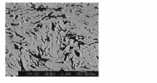
- the structure of the obtained sintered body of Example 1 was observed with a scanning electron microscope (SEM). Specifically, 10 locations in the cross section in the thickness direction of the sintered body of Example 1 (cross section of the sintered body in the pressing direction during hot pressing) were photographed with a scanning electron microscope (SEM). One SEM photograph was obtained. The 10 SEM photographs taken are all SEM photographs taken at a magnification of 1000 times with a field of view of 121 ⁇ m ⁇ 97 ⁇ m. One of 10 SEM photographs obtained by photographing is shown in FIG. The scale on the photograph shown in FIG. 1 is 10 ⁇ m.
- the gray phase is the FePt alloy phase
- the black phase is the C (carbon) phase.
- FIG. 2 is an image after the binarization processing of the SEM photograph shown in FIG. 1, wherein the white phase is the FePt alloy phase and the black phase is the C (carbon) phase.
- the size and shape of the C (carbon) phase were evaluated using 10 binarized images at 10 locations in the sintered body cross section.
- the procedures (1) to (6) for the evaluation will be described below.
- FIG. 2 is an example in which only five inscribed circles inscribed in the interface of the C (carbon) phase are listed in the binarized image, and the inscribed circle is hatched. Pulling. Also, FIG. 3 shows a binarized image that shows an enlarged region including one of the inscribed circles shown in FIG.
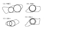
- FIG. 4 is a diagram for explaining the definition of “C-phase inscribed circle” in the present application.
- the “C-phase inscribed circle” in the present application is an inscribed circle circumscribing the C-phase interface in the binarized image.
- a plurality of inscribed circles may be drawn in one C phase.
- inscribed circles drawn in one C phase are drawn so as not to contact each other or circumscribed with each other (FIG. 4 ( A) (see FIG. 4 (B)), and cannot be drawn inscribed in each other (see FIG. 4 (B)), and drawn so as to cross each other (see FIG. 4 (C)). It cannot be drawn, and one cannot be drawn to contain the other (see FIG. 4D).
- FIG. 2 is an example describing a straight line having a maximum length L extending from the center of each inscribed circle toward the interface of the C (carbon) phase.
- a value L / R obtained by dividing the maximum length L by the radius R of the inscribed circle is obtained for each of the C phases from the largest diameter to the fifth.
- the average value of the obtained five values is defined as a C-phase non-spherical index b.
- the average value of the C phase size index a determined by the procedures (1) to (6) was 5.3 ⁇ m.
- the average value of the non-spherical index b of the C phase obtained by the procedures (1) to (6) was 4.5.
- a sputtering target having a diameter of 153 mm and a thickness of 2 mm was produced and joined to a Cu backing plate having a diameter of 161 mm and a thickness of 4 mm.
- the sputter target after bonding was set in a sputtering apparatus, and sputtering was performed at an output of 500 W and an Ar gas pressure in the chamber of 1 Pa, and the number of generated particles was evaluated. Specifically, the sputtering is temporarily stopped at each time point of the accumulated sputtering duration of 15 minutes, 30 minutes, 1 hour, and 2 hours, and a circular glass substrate having a diameter of 2.5 inches is set in the sputtering apparatus at each time point. Sputtering was performed for seconds.
- the sputtering cumulative duration is the cumulative time during which sputtering is performed.
- a circular glass substrate having a diameter of 2.5 inches that was sputtered for 20 seconds at each time point was taken out of the sputtering apparatus, set in an optical surface analyzer (optical surface analyzer), and the number of particles generated was measured. .
- the number obtained by subtracting the number of pre-sputtering particles counted in advance from the number of particles after sputtering at each time point was set to 1/10 to obtain the number of particles generated at each time point. That is, 1/10 of the number of particles generated by sputtering for 20 seconds was defined as the number of particles generated at each time point. This is in accordance with the fact that the sputtering time for forming the magnetic phase of the hard disk is about 2 seconds.
- the number of generated particles at each time point of the cumulative sputtering duration of 15 minutes, 30 minutes, 1 hour, and 2 hours was 33, 49, 62, and 80, respectively.
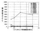
- the graph which plotted those values is shown in FIG. 5, FIG. 6 with the result in another Example and a comparative example. 5 and 6, the horizontal axis represents the cumulative sputtering duration (h), and the vertical axis represents the number of particles generated (number). 5 and FIG. 6 are different in the step of the scale on the vertical axis, FIG. 5 has a large step of the scale on the vertical axis, and FIG. 6 has a small step of the scale on the vertical axis.
- cross section in the thickness direction of the sintered body refers to the cross section in the thickness direction of the sputtering target in terms of the sputtering target.
- Example 2 In Example 2, in place of 36.31 g of non-spherical C powder having an average particle size of 12.17 ⁇ m used in Example 1, 36.31 g of non-spherical C powder having an average particle size of 19.93 ⁇ m was used. In the same manner as in Example 1, a sintered body and a sputtering target were produced. The composition of the target sintered body and sputtering target is 60.5 (50Fe-50Pt) -39.5C, as in Example 1.
- Example 2 Further, the carbon, oxygen and nitrogen contents in the produced sintered body were measured in the same manner as in Example 1.
- the carbon content was 6.01% by mass, the oxygen content was 199 mass ppm, The content was 14 mass ppm.
- Example 2 In the sintered body of Example 2, the average value of C phase size index a obtained in the same manner as in Example 1 was 6.3 ⁇ m. The average value of the non-spherical index b of the C phase obtained in the same manner as in Example 1 was 5.2.
- Example 2 As in Example 1, a sputtering target was produced using the obtained sintered body and sputtered, and the number of generated particles was evaluated. The number of particles generated at each time point of the cumulative sputtering duration of 15 minutes, 30 minutes, 1 hour, and 2 hours was 152, 62, 48, and 48, respectively. The graph which plotted those values is shown in FIG. 5, FIG. 6 with the result in another Example and a comparative example.
- Example 3 In Example 3, 36.31 g of nonspherical C powder having an average particle size of 51.01 ⁇ m was used instead of 36.31 g of nonspherical C powder having an average particle size of 12.17 ⁇ m used in Example 1. In the same manner as in Example 1, a sintered body and a sputtering target were produced. The composition of the target sintered body and sputtering target is 60.5 (50Fe-50Pt) -39.5C, as in Example 1.
- the carbon content was 5.99 mass%
- the oxygen content was 264 mass ppm
- the nitrogen content was The content was 10 ppm by mass.
- Example 3 In the sintered body of Example 3, the average value of C phase size index a obtained in the same manner as in Example 1 was 7.6 ⁇ m. Further, the average value of the non-spherical indices b of the C phase obtained in the same manner as in Example 1 was 6.0.
- Example 3 As in Example 1, a sputtering target was prepared using the obtained sintered body and sputtered, and the number of generated particles was evaluated. The number of generated particles at each time point of the cumulative sputtering duration of 15 minutes, 30 minutes, 1 hour, and 2 hours was 68, 67, 52, and 55, respectively. The graph which plotted those values is shown in FIG. 5, FIG. 6 with the result in another Example and a comparative example.
- Example 4 The target of the composition of the mixed powder, sintered body and target in Example 4 is 60 (50Fe-50Pt) -30C-10SiO 2 . That is, the target of the composition of the metal component is 50 mol% Fe-50 mol% Pt, and the target of the composition ratio of the FePt alloy, C (carbon) and SiO 2 is 60 mol% for FePt alloy, 30 mol% for C, and SiO 2 for SiO 2. 10 mol%.
- the C powder used in Example 4 is the same as the C powder used in Example 2, and is a non-spherical C powder having an average particle size of 19.93 ⁇ m. In Example 4, 17.46 g of the C powder was used.
- Example 4 SiO 2 powder having an average particle size of 0.7 ⁇ m was used.
- FePt alloy powder was produced by using a gas atomization method.
- SiO 2 powder 59.07 g was added to 740.00 g of the produced FePt alloy powder, and mixed for 57 hours at 462 rpm with a mixer using a ball to obtain a first mixed powder.
- the obtained powder mixture for pressure sintering is hot-pressed under conditions of a temperature of 1100 ° C., a pressure of 30.6 MPa, a time of 60 min, and an atmosphere of 5 ⁇ 10 ⁇ 2 Pa or less to obtain a sintered body.
- a temperature of 1100 ° C. a pressure of 30.6 MPa
- a time of 60 min a time of 60 min
- an atmosphere of 5 ⁇ 10 ⁇ 2 Pa or less was made.
- the average value of the C phase size index a was 5.4 ⁇ m. Moreover, the average value of the nonspherical index b of the C phase was 5.6.
- Example 4 As in Example 1, a sputtering target was prepared using the obtained sintered body and sputtered, and the number of generated particles was evaluated. The number of generated particles at each time point of the cumulative sputtering duration of 15 minutes, 30 minutes, 1 hour, and 2 hours was 13, 13, 18, and 17, respectively. The graph which plotted those values is shown in FIG. 5, FIG. 6 with the result in another Example and a comparative example.
- Comparative Example 1 In this comparative example 1, 36.31 g of spherical C powder having an average particle size of 6.63 ⁇ m was used instead of 36.31 g of nonspherical C powder having an average particle size of 12.17 ⁇ m used in Example 1, and A sintered body and a sputtering target were produced in the same manner as in Example 1 except that the obtained mixed powder for pressure sintering was hot pressed at 1100 ° C.
- the composition of the target sintered body and sputtering target is 60.5 (50Fe-50Pt) -39.5C, as in Example 1.
- the carbon content in the produced sintered body was measured with a carbon sulfur analyzer manufactured by HORIBA, and the oxygen and nitrogen contents were measured with a TC-600 type oxygen-nitrogen simultaneous analyzer manufactured by LECO.
- the content of was 6.07% by mass, the content of oxygen was 377 ppm by mass, and the content of nitrogen was 14 ppm by mass.
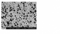
- the structure of the obtained sintered body of Example 1 was observed with a scanning electron microscope (SEM). Specifically, images were taken with a scanning electron microscope (SEM) at 10 points in the cross section in the thickness direction of the sintered body of Comparative Example 1 (cross section of the sintered body in the pressing direction during hot pressing). One SEM photograph was obtained. The 10 SEM photographs taken are all SEM photographs taken at a magnification of 1000 times with a field of view of 121 ⁇ m ⁇ 97 ⁇ m. One of the 10 SEM photographs obtained by photographing is shown in FIG. The scale in the photograph shown in FIG. 7 is 10 ⁇ m.
- the gray phase is the FePt alloy phase
- the black phase is the C (carbon) phase.
- FIG. 8 is an image after the binarization processing of the SEM photograph shown in FIG. 7, in which the white phase is the FePt alloy phase and the black phase is the C (carbon) phase.
- FIG. 8 only five inscribed circles inscribed in the interface of the C (carbon) phase are shown from the larger diameter, and the inscribed circle is hatched.
- FIG. 9 shows a binarized image that shows an enlarged area including one of the inscribed circles shown in FIG.
- the average value of the C phase size index a obtained in the same manner as in Example 1 was 6.6 ⁇ m.
- the average value of the non-spherical index b of the C phase obtained in the same manner as in Example 1 was 2.0.
- Example 1 Also in this Comparative Example 1, as in Example 1, a sputtering target was prepared using the obtained sintered body and sputtered, and the number of generated particles was evaluated. The number of generated particles at each time point of the cumulative sputtering duration of 15 minutes, 30 minutes, 1 hour, and 2 hours was 340, 156, 320, and 186, respectively. The graph which plotted those values is shown in FIG. 5, FIG. 6 with the result in another Example and a comparative example.
- Comparative Example 2 In this Comparative Example 2, 36.31 g of spherical C powder having an average particle size of 22.55 ⁇ m was used instead of 36.31 g of nonspherical C powder having an average particle size of 12.17 ⁇ m used in Example 1, and A sintered body and a sputtering target were produced in the same manner as in Example 1 except that the obtained mixed powder for pressure sintering was hot pressed at 1050 ° C.
- the composition of the target sintered body and sputtering target is 60.5 (50Fe-50Pt) -39.5C, as in Example 1.
- the carbon content was 5.90 mass%
- the oxygen content was 264 mass ppm
- the nitrogen content was The content was 28 mass ppm.
- Example 2 Also in this Comparative Example 2, as in Example 1, a sputtering target was prepared using the obtained sintered body and sputtered, and the number of generated particles was evaluated. The number of generated particles at each time point of the cumulative sputtering duration of 15 minutes, 30 minutes, 1 hour, and 2 hours was 842, 265, 108, and 110, respectively. The graph which plotted those values is shown in FIG. 5, FIG. 6 with the result in another Example and a comparative example.
- Comparative Example 3 In Comparative Example 3, 36.31 g of non-spherical C powder having an average particle size of 5.09 ⁇ m was used instead of 36.31 g of non-spherical C powder having an average particle size of 12.17 ⁇ m used in Example 1, and A sintered body and a sputtering target were prepared in the same manner as in Example 1 except that the obtained mixed powder for pressure sintering was hot pressed at 1300 ° C.
- the composition of the target sintered body and sputtering target is 60.5 (50Fe-50Pt) -39.5C, as in Example 1.
- the carbon content was 5.91 mass%
- the oxygen content was 211 mass ppm
- the nitrogen content was The content was 18 mass ppm.
- the average value of C phase size index a obtained in the same manner as in Example 1 was 3.7 ⁇ m. Further, the average value of the non-spherical indices b of the C phase obtained in the same manner as in Example 1 was 3.9.
- Example 3 As in Example 1, a sputtering target was prepared using the obtained sintered body and sputtered, and the number of generated particles was evaluated. The number of generated particles at each of the cumulative sputtering durations of 15 minutes, 30 minutes, 1 hour, and 2 hours was 165, 236, 305, and 360, respectively. The graph which plotted those values is shown in FIG. 5, FIG. 6 with the result in another Example and a comparative example.
- Comparative Example 4 the composition of the target sintered body and sputtering target is 60.5 (50Fe-50Pt) -39.5C, as in Example 1.
- the C powder used in Comparative Example 4 is carbon black in which secondary particles are formed with an average primary particle diameter (median diameter) of 30 nm (catalog value), and the shape of each C particle is non-uniform. It is spherical. In Comparative Example 4, 62.50 g of the C powder was used.
- an FePt alloy powder was produced using a gas atomization method.
- the average particle size of the obtained FePt alloy powder was 45 ⁇ m.
- C. 62.50 g of C powder was added to 1000.00 g of the produced FePt alloy powder, and mixed for 24 hours at 462 rpm with a mixer using a ball to obtain a mixed powder for pressure sintering.
- the obtained powder mixture for pressure sintering is hot-pressed under conditions of temperature: 1460 ° C., pressure: 26.2 MPa, time: 60 min, atmosphere: 5 ⁇ 10 ⁇ 2 Pa or less, and sintered body was made.
- the carbon, oxygen and nitrogen contents in the produced sintered body were measured in the same manner as in Example 1.
- the carbon content was 5.72% by mass
- the oxygen content was 23 mass ppm
- the content was 10 ppm by mass.
- the average value of C phase size index a obtained in the same manner as in Example 1 was 0.8 ⁇ m. Further, the average value of the non-spherical indices b of the C phase obtained in the same manner as in Example 1 was 3.5.
- Example 4 Also in this Comparative Example 4, as in Example 1, a sputtering target was prepared using the obtained sintered body and sputtered, and the number of generated particles was evaluated. The number of generated particles at each time point of the cumulative sputtering duration of 15 minutes, 30 minutes, 1 hour, and 2 hours was 3019, 3587, 5803, and 4807, respectively. The graph which plotted those values is shown in FIG. 5, FIG. 6 with the result in another Example and a comparative example.
- the number of particles generated when sputtering is performed using the sputtering target of Comparative Example 4 is much larger than that in Examples 1 to 4 and Comparative Examples 1 to 3. ing.
- the C powder used was carbon black having an average primary particle size (median diameter) of about 20 to 50 nm (catalog value 30 nm), forming secondary particles. It is considered that secondary particles are also formed in the FePt alloy phase.
- the C of the secondary particles is a state where the C of the primary particles is compacted, and the C of the primary particles inside the secondary particles is not covered with the FePt alloy. It is thought that it is easy to fall out of the target in the state and is likely to become particles. For this reason, it is considered that the number of particles generated when sputtering is performed using the sputtering target of Comparative Example 4 is much larger than that in Examples 1 to 4 and Comparative Examples 1 to 3.
- Example 1 The main data for Examples 1 to 4 and Comparative Examples 1 to 4 are summarized in Table 1 below.
- the composition of the target is 60.5 (50Fe-50Pt) -39.5C for Examples 1 to 3 and Comparative Examples 1 to 4, and only Example 4 is 60 (50Fe-50Pt) -30C-10SiO 2. It is.
- the average value of the size index a of the C phase in the sintered body is 4.0 ⁇ m or more and 9.0 ⁇ m or less, and the C phase in the sintered body
- the average value of the nonspherical index b is 3.0 or more.
- the average value of the size index a of the C phase in the sintered body is 4.0 ⁇ m or more and 9.0 ⁇ m or less.
- the size is easy to cover.
- the average value of the non-spherical index b of the C phase in the sintered body is 3.0 or more, the C phase in the target has an elongated shape compared to the spherical shape, and the surface area per unit volume is spherical. Is bigger than. For this reason, the C phase in the target tends to be well bonded to the FePt alloy that is a matrix metal.
- Comparative Examples 1 and 2 the average values of the non-spherical index b of the C phase in the sintered body were 2.0 and 2.5, respectively, both being less than 3.0, The shape of the C phase is nearly spherical. For this reason, in Comparative Examples 1 and 2, the surface area of the C phase in the sintered body per unit volume is small, and the C phase is weakly bonded to the FePt-based alloy that is the matrix metal. It is considered that the number of particles to be increased was larger than those in Examples 1 to 4.
- the primary particles of carbon form secondary particles in the sintered body.
- the C of the secondary particles is a state in which the C of the primary particles is compacted, and the primary particles of C inside the secondary particles are not covered with the FePt alloy. It is thought that it is easy to fall out of the target in the state and is likely to become particles. For this reason, it is considered that the number of particles generated when sputtering is performed using the sputtering target of Comparative Example 4 is much larger than that in Examples 1 to 4 and Comparative Examples 1 to 3.
Landscapes
- Chemical & Material Sciences (AREA)
- Engineering & Computer Science (AREA)
- Mechanical Engineering (AREA)
- Materials Engineering (AREA)
- Metallurgy (AREA)
- Organic Chemistry (AREA)
- Chemical Kinetics & Catalysis (AREA)
- Plasma & Fusion (AREA)
- Physics & Mathematics (AREA)
- Analytical Chemistry (AREA)
- Manufacturing & Machinery (AREA)
- Physical Vapour Deposition (AREA)
- Manufacturing Of Magnetic Record Carriers (AREA)
- Magnetic Record Carriers (AREA)
- Hard Magnetic Materials (AREA)
- Powder Metallurgy (AREA)
Abstract
Description
1-1.スパッタリングターゲットの構成成分および構造
本発明の第1実施形態に係るFePt-C系スパッタリングターゲットは、Fe、PtおよびCを含有するFePt-C系スパッタリングターゲットであって、Ptを33mol%以上60mol%以下含有して残部が実質的にFeからなるFePt系合金相中に、実質的にCからなるC相が分散した構造を有し、当該FePt-C系スパッタリングターゲットの厚さ方向の断面を121μm×97μmの範囲の視野について1000倍の倍率で10箇所撮影して得た10個の画像それぞれにおいて、C相の内接円の直径が大きい方から5番目までのその5つの直径の平均値をC相の大きさ指数aとするとともに、直径が大きい方から5番目までのC相の内接円の中心からそのC相の界面までを結ぶ直線の最大長さLを当該内接円の半径Rで除した値L/Rを、直径が大きい方から5番目までのC相それぞれについて求め、求めた5つの値の平均値をC相の非球形指数bとするとき、前記10個の画像それぞれにおいて求めた前記C相の大きさ指数aの平均値が4.0μm以上9.0μm以下であり、かつ、前記10個の画像それぞれにおいて求めた前記C相の非球形指数bの平均値が3.0以上であることを特徴とする。なお、本明細書では、数値範囲を表す際に「α以上β以下」のことを「α~β」と記すことがある。
FePt系合金は高温(例えば600℃以上)で熱処理をすることにより、高い結晶磁気異方性を持ったfct構造を備えることができるため、磁気記録媒体の記録層となる役割を有し、本発明の実施形態に係るFePt-C系スパッタリングターゲットにおいて主成分となる。
C(炭素)は、スパッタリングにより得られるFePtC系層中において、磁性粒子であるFePt系合金粒子同士を仕切る隔壁となり、FePtC系層中におけるFePt系合金粒子を小さく均一にする役割を有し、本第1実施形態に係るFePt-C系スパッタリングターゲットにおいて主成分の1つとなる。
本第1実施形態に係るFePt-C系スパッタリングターゲットの構造は、Ptを33mol%以上60mol%以下含有して残部が実質的にFeからなるFePt系合金相中に、実質的にCからなるC相が分散した構造である。そして、当該FePt-C系スパッタリングターゲットの厚さ方向の断面を121μm×97μmの範囲の視野について1000倍の倍率で10箇所撮影して得た10個の画像それぞれにおいて、C相の内接円の直径が大きい方から5番目までのその5つの直径の平均値をC相の大きさ指数aとするとともに、直径が大きい方から5番目までのC相の内接円の中心からそのC相の界面までを結ぶ直線の最大長さLを当該内接円の半径Rで除した値L/Rを、直径が大きい方から5番目までのC相それぞれについて求め、求めた5つの値の平均値をC相の非球形指数bとするとき、前記10個の画像それぞれにおいて求めた前記C相の大きさ指数aの平均値が4.0μm以上9.0μm以下であり、かつ、前記10個の画像それぞれにおいて求めた前記C相の非球形指数bの平均値が3.0以上である。
本第1実施形態に係るFePt-C系スパッタリングターゲットは、金属元素としてFeおよびPtのみ含んでいるが、FePt系合金相にFeおよびPt以外の元素を含ませてもよい(本第1実施形態の変形例)。
本第1実施形態に係るFePt-C系スパッタリングターゲットは、例えば、Ptを33mol%以上60mol%以下含有して残部が実質的にFeからなる平均粒径60μm以下のFePt系合金粉末、および、含まれるC粒子の平均粒径が8μm以上60μm以下で、かつ、含まれるC粒子の形状が非球形であるC粉末を混合して、加圧焼結用混合粉末を作製した後、作製した該加圧焼結用混合粉末を加圧下で加熱して成形することにより製造することができる。
本第1実施形態に係るFePt-C系スパッタリングターゲットの構造は、Ptを33mol%以上60mol%以下含有して残部が実質的にFeからなるFePt系合金相中に、実質的にCからなるC相が分散した構造である。そして、当該FePt-C系スパッタリングターゲットの厚さ方向の断面を121μm×97μmの範囲の視野について1000倍の倍率で10箇所撮影して得た10個の画像それぞれにおいて、C相の内接円の直径が大きい方から5番目までのその5つの直径の平均値をC相の大きさ指数aとするとともに、直径が大きい方から5番目までのC相の内接円の中心からそのC相の界面までを結ぶ直線の最大長さLを当該内接円の半径Rで除した値L/Rを、直径が大きい方から5番目までのC相それぞれについて求め、求めた5つの値の平均値をC相の非球形指数bとするとき、前記10個の画像それぞれにおいて求めた前記C相の大きさ指数aの平均値が4.0μm以上9.0μm以下であり、かつ、前記10個の画像それぞれにおいて求めた前記C相の非球形指数bの平均値が3.0以上である。
以下、第2実施形態に係るFePt-C系スパッタリングターゲットについて説明するが、第1実施形態に係るFePt-C系スパッタリングターゲットと同様の内容については適宜説明を省略する。
第1実施形態に係るFePt-C系スパッタリングターゲットでは、合金成分(Fe、Pt)以外の含有物はC(炭素)であったが、本第2実施形態に係るFePt-C系スパッタリングターゲットでは、合金成分(Fe、Pt)以外の含有物はC(炭素)と金属酸化物である。
本第2実施形態に係るFePt-C系スパッタリングターゲットにおけるFePt系合金について説明すべき内容は、第1実施形態の「1-1-1.FePt系合金について」で説明した内容と同様であるので、説明は省略する。
C(炭素)および酸化物は、スパッタリングにより得られるFePtC系層中において、磁性粒子であるFePt系合金粒子同士を仕切る隔壁となり、FePtC系層中におけるFePt系合金粒子を小さく均一にする役割を有し、本第2実施形態に係るFePt-C系スパッタリングターゲットにおいて主成分の1つとなる。
本第2実施形態に係るFePt-C系スパッタリングターゲットの構造は、Ptを33mol%以上60mol%以下含有して残部が実質的にFeからなるFePt系合金相中に、実質的にCからなるC相および実質的に酸化物からなる酸化物相が分散した構造である。そして、当該FePt-C系スパッタリングターゲットの厚さ方向の断面を121μm×97μmの範囲の視野について1000倍の倍率で10箇所撮影して得た10個の画像それぞれにおいて、C相の内接円の直径が大きい方から5番目までのその5つの直径の平均値をC相の大きさ指数aとするとともに、直径が大きい方から5番目までのC相の内接円の中心からそのC相の界面までを結ぶ直線の最大長さLを当該内接円の半径Rで除した値L/Rを、直径が大きい方から5番目までのC相それぞれについて求め、求めた5つの値の平均値をC相の非球形指数bとするとき、前記10個の画像それぞれにおいて求めた前記C相の大きさ指数aの平均値が4.0μm以上9.0μm以下であり、かつ、前記10個の画像それぞれにおいて求めた前記C相の非球形指数bの平均値が3.0以上である。
本第2実施形態に係るFePt-C系スパッタリングターゲットは、金属元素としてFeおよびPtのみ含んでいるが、FePt系合金相にFeおよびPt以外の元素を含ませてもよい(本第2実施形態の変形例)。
本第2実施形態に係るFePt-C系スパッタリングターゲットは、例えば、Ptを33mol%以上60mol%以下含有して残部が実質的にFeからなる平均粒径60μm以下のFePt系合金粉末、含まれるC粒子の平均粒径が8μm以上60μm以下で、かつ、含まれるC粒子の形状が非球形であるC粉末、および、酸化物粉末を混合して、加圧焼結用混合粉末を作製した後、作製した該加圧焼結用混合粉末を加圧下で加熱して成形することにより製造することができる。
本第2実施形態に係るFePt-C系スパッタリングターゲットの構造は、Ptを33mol%以上60mol%以下含有して残部が実質的にFeからなるFePt系合金相中に、実質的にCからなるC相および実質的に酸化物からなる酸化物相が分散した構造である。そして、当該FePt-C系スパッタリングターゲットの厚さ方向の断面を121μm×97μmの範囲の視野について1000倍の倍率で10箇所撮影して得た10個の画像それぞれにおいて、C相の内接円の直径が大きい方から5番目までのその5つの直径の平均値をC相の大きさ指数aとするとともに、直径が大きい方から5番目までのC相の内接円の中心からそのC相の界面までを結ぶ直線の最大長さLを当該内接円の半径Rで除した値L/Rを、直径が大きい方から5番目までのC相それぞれについて求め、求めた5つの値の平均値をC相の非球形指数bとするとき、前記10個の画像それぞれにおいて求めた前記C相の大きさ指数aの平均値が4.0μm以上9.0μm以下であり、かつ、前記10個の画像それぞれにおいて求めた前記C相の非球形指数bの平均値が3.0以上である。
本実施例1における混合粉末、焼結体およびターゲットの組成の目標は60.5(50Fe-50Pt)-39.5Cである。即ち、金属成分の組成の目標は50mol%Fe-50mol%Ptであり、FePt合金とC(炭素)の組成比の目標は、FePt合金が60.5mol%、Cが39.5mol%である。
本実施例2では、実施例1で用いた平均粒径12.17μmの非球形C粉末36.31gに替えて、平均粒径19.93μmの非球形C粉末36.31gを用いたこと以外は実施例1と同様にして、焼結体およびスパッタリングターゲットを作製した。目標とする焼結体およびスパッタリングターゲットの組成は、実施例1と同様に、60.5(50Fe-50Pt)-39.5Cである。
本実施例3では、実施例1で用いた平均粒径12.17μmの非球形C粉末36.31gに替えて、平均粒径51.01μmの非球形C粉末36.31gを用いたこと以外は実施例1と同様にして、焼結体およびスパッタリングターゲットを作製した。目標とする焼結体およびスパッタリングターゲットの組成は、実施例1と同様に、60.5(50Fe-50Pt)-39.5Cである。
本実施例4における混合粉末、焼結体およびターゲットの組成の目標は60(50Fe-50Pt)-30C-10SiO2である。即ち、金属成分の組成の目標は50mol%Fe-50mol%Ptであり、FePt合金とC(炭素)とSiO2の組成比の目標は、FePt合金が60mol%、Cが30mol%、SiO2が10mol%である。
本比較例1では、実施例1で用いた平均粒径12.17μmの非球形C粉末36.31gに替えて、平均粒径6.63μmの球形C粉末36.31gを用いたこと、および、得られた加圧焼結用混合粉末を1100℃でホットプレスしたこと以外は実施例1と同様にして、焼結体およびスパッタリングターゲットを作製した。目標とする焼結体およびスパッタリングターゲットの組成は、実施例1と同様に、60.5(50Fe-50Pt)-39.5Cである。
本比較例2では、実施例1で用いた平均粒径12.17μmの非球形C粉末36.31gに替えて、平均粒径22.55μmの球形C粉末36.31gを用いたこと、および、得られた加圧焼結用混合粉末を1050℃でホットプレスしたこと以外は実施例1と同様にして、焼結体およびスパッタリングターゲットを作製した。目標とする焼結体およびスパッタリングターゲットの組成は、実施例1と同様に、60.5(50Fe-50Pt)-39.5Cである。
本比較例3では、実施例1で用いた平均粒径12.17μmの非球形C粉末36.31gに替えて、平均粒径5.09μmの非球形C粉末36.31gを用いたこと、および、得られた加圧焼結用混合粉末を1300℃でホットプレスしたこと以外は実施例1と同様にして、焼結体およびスパッタリングターゲットを作製した。目標とする焼結体およびスパッタリングターゲットの組成は、実施例1と同様に、60.5(50Fe-50Pt)-39.5Cである。
本比較例4において、目標とする焼結体およびスパッタリングターゲットの組成は、実施例1と同様に、60.5(50Fe-50Pt)-39.5Cである。
実施例1~4、比較例1~4についての主要なデータを次の表1にまとめて示す。ターゲットの組成は、実施例1~3、比較例1~4については、60.5(50Fe-50Pt)-39.5Cであり、実施例4のみ、60(50Fe-50Pt)-30C-10SiO2である。

Claims (10)
- Fe、PtおよびCを含有するFePt-C系スパッタリングターゲットであって、
Ptを33mol%以上60mol%以下含有して残部が実質的にFeからなるFePt系合金相中に、実質的にCからなるC相が分散した構造を有し、
当該FePt-C系スパッタリングターゲットの厚さ方向の断面を121μm×97μmの範囲の視野について1000倍の倍率で10箇所撮影して得た10個の画像それぞれにおいて、C相の内接円の直径が大きい方から5番目までのその5つの直径の平均値をC相の大きさ指数aとするとともに、直径が大きい方から5番目までのC相の内接円の中心からそのC相の界面までを結ぶ直線の最大長さLを当該内接円の半径Rで除した値L/Rを、直径が大きい方から5番目までのC相それぞれについて求め、求めた5つの値の平均値をC相の非球形指数bとするとき、前記10個の画像それぞれにおいて求めた前記C相の大きさ指数aの平均値が4.0μm以上9.0μm以下であり、かつ、前記10個の画像それぞれにおいて求めた前記C相の非球形指数bの平均値が3.0以上であることを特徴とするFePt-C系スパッタリングターゲット。 - Fe、PtおよびCを含有し、さらにFe、Pt以外の1種以上の元素を含有するFePt-C系スパッタリングターゲットであって、
Ptを33mol%以上60mol%未満、Fe、Pt以外の前記1種以上の元素を0mol%よりも多く20mol%以下含有し、かつ、Ptと前記1種以上の元素の合計が60mol%以下であり、残部が実質的にFeからなるFePt系合金相中に、実質的にCからなるC相が分散した構造を有し、
当該FePt-C系スパッタリングターゲットの厚さ方向の断面を121μm×97μmの範囲の視野について1000倍の倍率で10箇所撮影して得た10個の画像それぞれにおいて、C相の内接円の直径が大きい方から5番目までのその5つの直径の平均値をC相の大きさ指数aとするとともに、直径が大きい方から5番目までのC相の内接円の中心からそのC相の界面までを結ぶ直線の最大長さLを当該内接円の半径Rで除した値L/Rを、直径が大きい方から5番目までのC相それぞれについて求め、求めた5つの値の平均値をC相の非球形指数bとするとき、前記10個の画像それぞれにおいて求めた前記C相の大きさ指数aの平均値が4.0μm以上9.0μm以下であり、かつ、前記10個の画像それぞれにおいて求めた前記C相の非球形指数bの平均値が3.0以上であることを特徴とするFePt-C系スパッタリングターゲット。 - Fe、Pt以外の前記1種以上の元素は、Cu、Ag、Rh、Au、Mn、Ni、Co、Pd、Cr、V、Bのうちの1種以上であることを特徴とする請求項2に記載のFePt-C系スパッタリングターゲット。
- 前記C相に含まれるCのターゲット全体に対する含有割合が10mol%以上60mol%以下であることを特徴とする請求項1~3のいずれかに記載のFePt-C系スパッタリングターゲット。
- Fe、Pt、Cおよび酸化物を含有するFePt-C系スパッタリングターゲットであって、
Ptを33mol%以上60mol%以下含有して残部が実質的にFeからなるFePt系合金相中に、実質的にCからなるC相および実質的に酸化物からなる酸化物相が分散した構造を有し、
当該FePt-C系スパッタリングターゲットの厚さ方向の断面を121μm×97μmの範囲の視野について1000倍の倍率で10箇所撮影して得た10個の画像それぞれにおいて、C相の内接円の直径が大きい方から5番目までのその5つの直径の平均値をC相の大きさ指数aとするとともに、直径が大きい方から5番目までのC相の内接円の中心からそのC相の界面までを結ぶ直線の最大長さLを当該内接円の半径Rで除した値L/Rを、直径が大きい方から5番目までのC相それぞれについて求め、求めた5つの値の平均値をC相の非球形指数bとするとき、前記10個の画像それぞれにおいて求めた前記C相の大きさ指数aの平均値が4.0μm以上9.0μm以下であり、かつ、前記10個の画像それぞれにおいて求めた前記C相の非球形指数bの平均値が3.0以上であることを特徴とするFePt-C系スパッタリングターゲット。 - Fe、Pt、Cおよび酸化物を含有し、さらにFe、Pt以外の1種以上の元素を含有するFePt-C系スパッタリングターゲットであって、
Ptを33mol%以上60mol%未満、Fe、Pt以外の前記1種以上の元素を0mol%よりも多く20mol%以下含有し、かつ、Ptと前記1種以上の元素の合計が60mol%以下であり、残部が実質的にFeからなるFePt系合金相中に、実質的にCからなるC相および実質的に酸化物からなる酸化物相が分散した構造を有し、
当該FePt-C系スパッタリングターゲットの厚さ方向の断面を121μm×97μmの範囲の視野について1000倍の倍率で10箇所撮影して得た10個の画像それぞれにおいて、C相の内接円の直径が大きい方から5番目までのその5つの直径の平均値をC相の大きさ指数aとするとともに、直径が大きい方から5番目までのC相の内接円の中心からそのC相の界面までを結ぶ直線の最大長さLを当該内接円の半径Rで除した値L/Rを、直径が大きい方から5番目までのC相それぞれについて求め、求めた5つの値の平均値をC相の非球形指数bとするとき、前記10個の画像それぞれにおいて求めた前記C相の大きさ指数aの平均値が4.0μm以上9.0μm以下であり、かつ、前記10個の画像それぞれにおいて求めた前記C相の非球形指数bの平均値が3.0以上であることを特徴とするFePt-C系スパッタリングターゲット。 - Fe、Pt以外の前記1種以上の元素は、Cu、Ag、Rh、Au、Mn、Ni、Co、Pd、Cr、V、Bのうちの1種以上であることを特徴とする請求項6に記載のFePt-C系スパッタリングターゲット。
- 前記C相に含まれるCおよび前記酸化物相に含まれる酸化物の合計のターゲット全体に対する含有割合が10mol%以上60mol%以下であって、かつ、前記C相に含まれるCのターゲット全体に対する含有割合が5mol%以上50mol以下、前記酸化物相に含まれる酸化物の合計のターゲット全体に対する含有割合が1mol%以上25mol%以下であることを特徴とする請求項5~7のいずれかに記載のFePt-C系スパッタリングターゲット。
- 前記酸化物は、SiO2、TiO2、Ti2O3、Ta2O5、Cr2O3、CoO、Co3O4、B2O3、Fe2O3、Fe3O4、CuO、Cu2O、Y2O3、MgO、Al2O3、ZrO2、Nb2O5、MoO3、CeO2、Sm2O3、Gd2O3、WO2、WO3、HfO2、NiO2のうちの少なくとも1種を含むことを特徴とする請求項5~8のいずれかに記載のFePt-C系スパッタリングターゲット。
- 相対密度が90%以上であることを特徴とする請求項1~9のいずれかに記載のFePt-C系スパッタリングターゲット。
Priority Applications (5)
| Application Number | Priority Date | Filing Date | Title |
|---|---|---|---|
| US16/078,003 US10787732B2 (en) | 2016-03-07 | 2017-03-02 | FePt-C-based sputtering target |
| SG11201806891QA SG11201806891QA (en) | 2016-03-07 | 2017-03-02 | Fept-c-based sputtering target |
| MYPI2018703176A MY192178A (en) | 2016-03-07 | 2017-03-02 | Fept-c-based sputtering target |
| CN201780014311.5A CN108699679B (zh) | 2016-03-07 | 2017-03-02 | FePt-C系溅射靶 |
| JP2018504427A JP6383510B2 (ja) | 2016-03-07 | 2017-03-02 | FePt−C系スパッタリングターゲット |
Applications Claiming Priority (2)
| Application Number | Priority Date | Filing Date | Title |
|---|---|---|---|
| JP2016-043888 | 2016-03-07 | ||
| JP2016043888 | 2016-03-07 |
Publications (1)
| Publication Number | Publication Date |
|---|---|
| WO2017154741A1 true WO2017154741A1 (ja) | 2017-09-14 |
Family
ID=59789542
Family Applications (1)
| Application Number | Title | Priority Date | Filing Date |
|---|---|---|---|
| PCT/JP2017/008344 Ceased WO2017154741A1 (ja) | 2016-03-07 | 2017-03-02 | FePt-C系スパッタリングターゲット |
Country Status (7)
| Country | Link |
|---|---|
| US (1) | US10787732B2 (ja) |
| JP (1) | JP6383510B2 (ja) |
| CN (1) | CN108699679B (ja) |
| MY (1) | MY192178A (ja) |
| SG (1) | SG11201806891QA (ja) |
| TW (1) | TWI675926B (ja) |
| WO (1) | WO2017154741A1 (ja) |
Cited By (4)
| Publication number | Priority date | Publication date | Assignee | Title |
|---|---|---|---|---|
| JP2019116682A (ja) * | 2017-12-27 | 2019-07-18 | 光洋應用材料科技股▲分▼有限公司 | ルテニウム/レニウムを含むスパッタリングターゲット、ルテニウム/レニウムを含む層およびその製法 |
| WO2020066826A1 (ja) * | 2018-09-28 | 2020-04-02 | 宇部マテリアルズ株式会社 | スパッタリングターゲット及び磁気記録媒体 |
| WO2021235380A1 (ja) * | 2020-05-18 | 2021-11-25 | 田中貴金属工業株式会社 | Pt-酸化物系スパッタリングターゲット及び垂直磁気記録媒体 |
| WO2023079857A1 (ja) * | 2021-11-05 | 2023-05-11 | Jx金属株式会社 | Fe-Pt-C系スパッタリングターゲット部材、スパッタリングターゲット組立品、成膜方法、及びスパッタリングターゲット部材の製造方法 |
Families Citing this family (2)
| Publication number | Priority date | Publication date | Assignee | Title |
|---|---|---|---|---|
| US20200234730A1 (en) * | 2018-03-27 | 2020-07-23 | Jx Nippon Mining & Metals Corporation | Sputtering target and method for producing same, and method for producing magnetic recording medium |
| TWI761264B (zh) * | 2021-07-15 | 2022-04-11 | 光洋應用材料科技股份有限公司 | 鐵鉑銀基靶材及其製法 |
Citations (6)
| Publication number | Priority date | Publication date | Assignee | Title |
|---|---|---|---|---|
| JP2012214874A (ja) * | 2011-03-30 | 2012-11-08 | Tanaka Kikinzoku Kogyo Kk | FePt−C系スパッタリングターゲット及びその製造方法 |
| WO2013105648A1 (ja) * | 2012-01-13 | 2013-07-18 | 田中貴金属工業株式会社 | FePt系スパッタリングターゲット及びその製造方法 |
| WO2014013920A1 (ja) * | 2012-07-20 | 2014-01-23 | Jx日鉱日石金属株式会社 | 磁気記録膜形成用スパッタリングターゲット及びその製造方法 |
| JP2014120180A (ja) * | 2012-12-13 | 2014-06-30 | Showa Denko Kk | スパッタリングターゲット、スパッタリングターゲットの製造方法、磁気記録媒体の製造方法および磁気記録再生装置 |
| WO2014175392A1 (ja) * | 2013-04-26 | 2014-10-30 | Jx日鉱日石金属株式会社 | 磁気記録膜用スパッタリングターゲット及びその製造に用いる炭素原料 |
| JP2015175025A (ja) * | 2014-03-14 | 2015-10-05 | Jx日鉱日石金属株式会社 | C粒子が分散したFe−Pt系スパッタリングターゲット |
Family Cites Families (4)
| Publication number | Priority date | Publication date | Assignee | Title |
|---|---|---|---|---|
| KR100470151B1 (ko) | 2002-10-29 | 2005-02-05 | 한국과학기술원 | FePtC 박막을 이용한 고밀도 자기기록매체 및 그제조방법 |
| JP5590322B2 (ja) | 2010-11-12 | 2014-09-17 | 三菱マテリアル株式会社 | 磁気記録媒体膜形成用スパッタリングターゲットおよびその製造方法 |
| JP5592022B2 (ja) * | 2012-06-18 | 2014-09-17 | Jx日鉱日石金属株式会社 | 磁気記録膜用スパッタリングターゲット |
| JP5965539B2 (ja) | 2013-03-01 | 2016-08-10 | 田中貴金属工業株式会社 | FePt−C系スパッタリングターゲット |
-
2017
- 2017-03-02 US US16/078,003 patent/US10787732B2/en not_active Expired - Fee Related
- 2017-03-02 CN CN201780014311.5A patent/CN108699679B/zh not_active Expired - Fee Related
- 2017-03-02 JP JP2018504427A patent/JP6383510B2/ja active Active
- 2017-03-02 WO PCT/JP2017/008344 patent/WO2017154741A1/ja not_active Ceased
- 2017-03-02 MY MYPI2018703176A patent/MY192178A/en unknown
- 2017-03-02 SG SG11201806891QA patent/SG11201806891QA/en unknown
- 2017-03-06 TW TW106107237A patent/TWI675926B/zh active
Patent Citations (6)
| Publication number | Priority date | Publication date | Assignee | Title |
|---|---|---|---|---|
| JP2012214874A (ja) * | 2011-03-30 | 2012-11-08 | Tanaka Kikinzoku Kogyo Kk | FePt−C系スパッタリングターゲット及びその製造方法 |
| WO2013105648A1 (ja) * | 2012-01-13 | 2013-07-18 | 田中貴金属工業株式会社 | FePt系スパッタリングターゲット及びその製造方法 |
| WO2014013920A1 (ja) * | 2012-07-20 | 2014-01-23 | Jx日鉱日石金属株式会社 | 磁気記録膜形成用スパッタリングターゲット及びその製造方法 |
| JP2014120180A (ja) * | 2012-12-13 | 2014-06-30 | Showa Denko Kk | スパッタリングターゲット、スパッタリングターゲットの製造方法、磁気記録媒体の製造方法および磁気記録再生装置 |
| WO2014175392A1 (ja) * | 2013-04-26 | 2014-10-30 | Jx日鉱日石金属株式会社 | 磁気記録膜用スパッタリングターゲット及びその製造に用いる炭素原料 |
| JP2015175025A (ja) * | 2014-03-14 | 2015-10-05 | Jx日鉱日石金属株式会社 | C粒子が分散したFe−Pt系スパッタリングターゲット |
Cited By (10)
| Publication number | Priority date | Publication date | Assignee | Title |
|---|---|---|---|---|
| JP2019116682A (ja) * | 2017-12-27 | 2019-07-18 | 光洋應用材料科技股▲分▼有限公司 | ルテニウム/レニウムを含むスパッタリングターゲット、ルテニウム/レニウムを含む層およびその製法 |
| WO2020066826A1 (ja) * | 2018-09-28 | 2020-04-02 | 宇部マテリアルズ株式会社 | スパッタリングターゲット及び磁気記録媒体 |
| JPWO2020066826A1 (ja) * | 2018-09-28 | 2021-09-24 | 宇部マテリアルズ株式会社 | スパッタリングターゲット及び磁気記録媒体 |
| JP7396993B2 (ja) | 2018-09-28 | 2023-12-12 | 宇部マテリアルズ株式会社 | 磁気記録媒体 |
| WO2021235380A1 (ja) * | 2020-05-18 | 2021-11-25 | 田中貴金属工業株式会社 | Pt-酸化物系スパッタリングターゲット及び垂直磁気記録媒体 |
| JPWO2021235380A1 (ja) * | 2020-05-18 | 2021-11-25 | ||
| CN115552052A (zh) * | 2020-05-18 | 2022-12-30 | 田中贵金属工业株式会社 | Pt-氧化物系溅射靶和垂直磁记录介质 |
| WO2023079857A1 (ja) * | 2021-11-05 | 2023-05-11 | Jx金属株式会社 | Fe-Pt-C系スパッタリングターゲット部材、スパッタリングターゲット組立品、成膜方法、及びスパッタリングターゲット部材の製造方法 |
| JPWO2023079857A1 (ja) * | 2021-11-05 | 2023-05-11 | ||
| JP7657960B2 (ja) | 2021-11-05 | 2025-04-07 | Jx金属株式会社 | Fe-Pt-C系スパッタリングターゲット部材、スパッタリングターゲット組立品、成膜方法、及びスパッタリングターゲット部材の製造方法 |
Also Published As
| Publication number | Publication date |
|---|---|
| TWI675926B (zh) | 2019-11-01 |
| JP6383510B2 (ja) | 2018-08-29 |
| US10787732B2 (en) | 2020-09-29 |
| TW201809329A (zh) | 2018-03-16 |
| CN108699679A (zh) | 2018-10-23 |
| CN108699679B (zh) | 2020-09-29 |
| SG11201806891QA (en) | 2018-09-27 |
| JPWO2017154741A1 (ja) | 2018-10-04 |
| MY192178A (en) | 2022-08-04 |
| US20190292650A1 (en) | 2019-09-26 |
Similar Documents
| Publication | Publication Date | Title |
|---|---|---|
| JP6383510B2 (ja) | FePt−C系スパッタリングターゲット | |
| JP5965539B2 (ja) | FePt−C系スパッタリングターゲット | |
| JP6359622B2 (ja) | Co又はFeを含有するスパッタリングターゲット | |
| JP5946974B1 (ja) | スパッタリングターゲット | |
| JP2009132975A (ja) | 比透磁率の低い垂直磁気記録媒体膜形成用スパッタリングターゲット | |
| JP5863783B2 (ja) | FePt系スパッタリングターゲット及びその製造方法 | |
| TWI642798B (zh) | 濺鍍靶 | |
| JP2010090412A (ja) | Pd−Cr−W系スパッタリングターゲット及びその製造方法 | |
| JP6713489B2 (ja) | 磁気記録媒体用スパッタリングターゲット及び磁性薄膜 | |
| JP6029009B2 (ja) | 薄膜形成用スパッタリングターゲット及びその製造方法 | |
| WO2024014156A1 (ja) | Co-Cr-Pt-酸化物系スパッタリングターゲット | |
| CN111133126B (zh) | 能够稳定放电的溅射靶 | |
| JP7483999B1 (ja) | スパッタリングターゲット及びスパッタリングターゲット組立品 | |
| JP2009132976A (ja) | 比透磁率の低い垂直磁気記録媒体膜形成用スパッタリングターゲット | |
| JP5699017B2 (ja) | Pd−V合金系スパッタリングターゲット及びその製造方法 | |
| WO2025062836A1 (ja) | スパッタリングターゲット及びスパッタリングターゲット組立品 | |
| JP2025167932A (ja) | スパッタリングターゲット及びスパッタリングターゲット組立品 | |
| JP2023148386A (ja) | 磁気記録媒体の軟磁性層用FeCo系合金 |
Legal Events
| Date | Code | Title | Description |
|---|---|---|---|
| DPE1 | Request for preliminary examination filed after expiration of 19th month from priority date (pct application filed from 20040101) | ||
| ENP | Entry into the national phase |
Ref document number: 2018504427 Country of ref document: JP Kind code of ref document: A |
|
| WWE | Wipo information: entry into national phase |
Ref document number: 11201806891Q Country of ref document: SG |
|
| NENP | Non-entry into the national phase |
Ref country code: DE |
|
| 121 | Ep: the epo has been informed by wipo that ep was designated in this application |
Ref document number: 17763081 Country of ref document: EP Kind code of ref document: A1 |
|
| 122 | Ep: pct application non-entry in european phase |
Ref document number: 17763081 Country of ref document: EP Kind code of ref document: A1 |