WO2017138095A1 - Dispositif d'humidification et climatiseur - Google Patents
Dispositif d'humidification et climatiseur Download PDFInfo
- Publication number
- WO2017138095A1 WO2017138095A1 PCT/JP2016/053822 JP2016053822W WO2017138095A1 WO 2017138095 A1 WO2017138095 A1 WO 2017138095A1 JP 2016053822 W JP2016053822 W JP 2016053822W WO 2017138095 A1 WO2017138095 A1 WO 2017138095A1
- Authority
- WO
- WIPO (PCT)
- Prior art keywords
- water
- humidifier
- absorbing
- humidification
- end side
- Prior art date
Links
Images


Classifications
-
- F—MECHANICAL ENGINEERING; LIGHTING; HEATING; WEAPONS; BLASTING
- F24—HEATING; RANGES; VENTILATING
- F24F—AIR-CONDITIONING; AIR-HUMIDIFICATION; VENTILATION; USE OF AIR CURRENTS FOR SCREENING
- F24F6/00—Air-humidification, e.g. cooling by humidification
- F24F6/02—Air-humidification, e.g. cooling by humidification by evaporation of water in the air
- F24F6/04—Air-humidification, e.g. cooling by humidification by evaporation of water in the air using stationary unheated wet elements
-
- F—MECHANICAL ENGINEERING; LIGHTING; HEATING; WEAPONS; BLASTING
- F24—HEATING; RANGES; VENTILATING
- F24F—AIR-CONDITIONING; AIR-HUMIDIFICATION; VENTILATION; USE OF AIR CURRENTS FOR SCREENING
- F24F6/00—Air-humidification, e.g. cooling by humidification
- F24F2006/008—Air-humidifier with water reservoir
Definitions
- the present invention relates to a humidifier and an air conditioner.
- Providing the appropriate humidity is one of the important factors in creating a comfortable indoor air environment. This is because lack of humidity can affect human health, deterioration of goods, generation of static electricity, and the like.
- the building hygiene management law stipulates a relative humidity with respect to a temperature of 17 to 28 ° C as a management standard value of the air environment. Is maintained at 40 to 70%.
- ASHRAE American Society for Heating, Refrigerating and Air Conditioning
- a humidity standard with a relative humidity of 30 to 60% is specified.
- a vaporization method is known as an indoor humidification method for humidifying a room.
- the vaporization method is a method in which a water-absorbing humidifier having water absorption performance is prepared, moisture is supplied to the water-absorbent humidifier, and humidification is performed by passing air through the water-absorbent humidifier.
- the moisture contained in the water-absorbent humidifier exchanges heat with the air current, thereby evaporating and evaporating the room (for example, Patent Document 1 and Patent Document). 2).
- Tap water is generally used as water to be supplied to the water-absorbing humidifier.
- tap water contains mineral components such as calcium carbonate, magnesium, and silica, and the possibility of scale deposition is high.
- scale is deposited on the filter, the water absorption performance of the water absorbent humidifier is lowered, and thus it is necessary to replace the water absorbent humidifier.
- vaporization evaporation is generally promoted by passing air from one end side to the other end side of the water-absorbing humidifier.
- the wind is passed in this way, the vaporization evaporation rate at the one end side portion of the water-absorbing humidifier directly hit by the wind is much larger than the vaporization evaporation rate at the other end portion of the water-absorbent humidifier.
- the water-absorbing humidifier is more water-absorbing than the other end.
- a scale can be deposited at an early stage at one end portion of the humidifying material. When scale is deposited on one end of the water-absorbing humidifier, the water absorption performance of the one end decreases, and the evaporation rate of the one end decreases, resulting in the vaporization rate of the entire water-absorbing humidifier. Significantly decreases, and as a result, the humidification performance decreases.
- the water-absorbing humidifier can be replaced even if the scale is not deposited on the other end of the water-absorbing humidifier. It becomes necessary. That is, the replacement cycle of the water-absorbing humidifier is shortened.
- the present invention has been made to solve the above-described problems, and provides a humidifier and an air conditioner including the humidifier that can make the water-absorbing humidifier replacement cycle as long as possible. With the goal.
- a humidifier according to the present invention includes a plate-like water-absorbing humidifier formed of a water-absorbing member, a supply means for supplying water to the water-absorbent humidifier, and a direction perpendicular to the plate thickness direction of the water-absorbent humidifier.
- the air conditioner according to the present invention includes a heat exchanger that exchanges heat with the blown air and the humidifier described above, and the humidifier humidifies the air that the heat exchanger has exchanged the heat with. Perform air conditioning by doing.
- a plurality of openings are distributed on the flat plate surface of the plate-like water-absorbing humidifier.
- the opening portion that opens in the plate thickness direction of the water-absorbing humidifier the area of contact with the wind increases, and thus the evaporation rate increases.
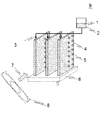
- FIG. 1 is a configuration diagram of a humidifier according to Embodiment 1.
- FIG. It is a block diagram which shows the partial expanded sectional view of a water absorbing humidifier. It is a figure which shows the shape of a humidification material. It is a block diagram which shows an example of the air conditioning conditioner mounted with a humidifier. It is a schematic diagram which shows the mechanism of humidification. It is a figure which shows the humidification effect by an opening part.
- FIG. 1 shows a humidifier 9 according to the first embodiment.
- the humidifier 9 according to the first embodiment includes a supply unit 2, a nozzle 3, a water absorbent humidifier 4, a drain pan 6, and a blower 8.
- the supply unit 2 is configured to store the humidified water 1 used for humidification of the humidified space to be humidified, and functions as a supply unit that supplies the humidified water 1 to the water absorbent humidifier 4.
- the nozzle 3 is an example of a water supply means for supplying the humidified water 1 from the supply unit 2 to the water absorbent humidifier 4.
- the water-absorbing humidifier 4 is configured to absorb the humidified water 1 supplied from the supply unit 2. When air is passed through the water-absorbing humidifying material 4, the absorbed humidifying water 1 is vaporized and evaporated, and humidification of the humidifying space is executed.
- the drain pan 6 is arranged on the lower side in the vertical direction of the water absorbent humidifier 4 and is configured to receive excess water from the water absorbent humidifier 4.
- the water absorbent humidifier 4 is formed in a plate shape with a water absorbent member, and a plurality of water absorbent humidifiers 4 are juxtaposed with a gap space in the short axis direction.
- FIG. 1 shows an example in which three water-absorbing humidifiers 4 are juxtaposed in the horizontal direction and each water-absorbing humidifier 4 is erected in the vertical direction, at least one water-absorbing humidifier is shown. It is sufficient if the material 4 is erected.
- the blower 8 is configured to flow air 7 from one end side to the other end side of the water absorbent humidifier 4 in the direction of ventilation perpendicular to the plate thickness direction and the juxtaposition direction of the water absorbent humidifier 4. This ventilation direction is different from the vertical direction.
- the supply unit 2, the nozzle 3, the water absorbent humidifier 4, the blower 8, and the drain pan 6 may be fixed by a predetermined support body or the like.
- the structure of this support body is not specifically limited, What is necessary is just to select suitably according to the use of the humidification apparatus 9. FIG.
- FIG. 2 is a partially enlarged cross-sectional view of the water-absorbing humidifier 4.
- the water-absorbing humidifying material 4 has a three-dimensional network structure including a trunk portion 11 and a gap portion 10 formed in the trunk portion 11, and is configured to improve water absorption.
- the three-dimensional network structure means a structure similar to a resin foam having high water absorption such as sponge.
- the material of the water-absorbing / humidifying material 4 according to Embodiment 1 may be, for example, a porous metal, ceramic, resin, non-woven fabric, fiber, foam, or mesh body. It is not something that can be done.
- the humidified water 1 according to Embodiment 1 is used for the purpose of humidifying a humidified space, and tap water is used as an example.
- mineral components such as calcium carbonate, magnesium, and silica contained in water such as tap water react with carbon dioxide, a hardly soluble substance that is hardly soluble in water is generated.
- the produced poorly soluble substance precipitates as it evaporates and changes in quality and appears as a scale.
- generated in the water absorbing humidifier 4 there exists a possibility that the space
- the humidified water 1 is preferably water with few mineral components, but soft water, hard water, or the like may be used.
- the supply unit 2 stores the humidified water 1 and supplies the humidified water 1 to the water-absorbing humidifying material 4.
- the humidifying water 1 is supplied from the nozzle 3 to the water-absorbing humidifying material 4 using a driving unit such as a pump. 1 is dropped and supplied.
- the drive part should just be what can convey the humidification water 1, for example, is a non-displacement pump or a positive displacement pump etc., and is not specifically limited.
- the drain pan 6 to which the humidified water 1 is supplied from the nozzle 3 may function as the supply unit 2. For example, by providing one end of the water-absorbing humidifying material 4 inside the drain pan 6, the configuration may be such that the humidifying water 1 is sucked and supplied by the capillary force of the water-absorbing humidifying material 4.
- the nozzle 3 is also installed on the upper part of the water-absorbing humidifier 4 in the region with the highest humidification performance, and supplies the humidified water 1 conveyed from the supply unit 2 by dropping from the upper part of the water-absorbent humidifier 4. Is. Further, the humidified water 1 may be supplied from the nozzle 3 to the supply unit 2.
- the nozzle 3 has a hollow shape, and its outer diameter and inner diameter may be selected according to the size and thickness of the water-absorbing humidifier 4.
- the tip shape of the nozzle 3 may be any shape such as a triangular pyramid shape, a quadrangular pyramid shape, a circular tube shape, and a square tube shape.
- the tip has a triangular pyramid shape and the outlet hole diameter is 0.5 mm. This is because water droplets are better when the tip has an acute angle.
- the tip having an acute angle is preferable. However, if the tip is excessively acute, handling becomes difficult and the strength becomes brittle. Therefore, the tip angle is preferably in the range of 10 to 45 degrees.
- the hole diameter at the outlet of the nozzle 3 is excessively large, the humidified water 1 is excessively supplied and there is a possibility that waste water increases.
- the hole diameter at the outlet of the nozzle 3 is excessively small, the outlet of the nozzle 3 is likely to be clogged with particles or scales mixed in the humidified water 1. Therefore, the hole diameter is preferably in the range of 0.1 to 0.6 mm.
- the material of the nozzle 3 may be a metal such as stainless steel, tungsten, titanium, silver, or copper, a resin such as PTFE, polyethylene, or polypropylene, or any other suitable material.
- a plurality of nozzles 3 for one water absorbent humidifier 4. May be provided.
- the length in the ventilation direction is 60 mm or less, one nozzle 3 may be provided for one water-absorbing humidifier 4, but if it exceeds 60 mm, a plurality of one water-absorbing humidifier 4 is provided. Nozzle 3 may be provided.
- the amount of water supplied for the humidified water 1 needs to be larger than the amount of water actually used for humidification. However, excessive supply of the humidified water 1 causes an increase in wasted water, so control it to an appropriate amount. Is desirable.
- the humidifying performance per unit area of the water-absorbing humidifier 4 is 2000 mL / h / m 2
- the size of the water-absorbing humidifier 4 is 200 ⁇ 50 mm
- the front and back surfaces can be humidified.
- the humidification amount per sheet of the water-absorbing humidifying material 4 is 40 mL / h, it is desirable to supply in the range of 60 to 200 mL / h, which is 1.5 to 5 times as much as that.
- the number of nozzles 3 increases, and the amount of water supplied from each nozzle 3 may become uneven. Therefore, a fiber, a resin, or a metal water absorbing body may be provided between the nozzle 3 and the water absorbing humidifying material 4 so as to be in contact with the water absorbing humidifying material 4. This is because even when a plurality of water-absorbing / humidifying materials 4 are arranged, the humidifying water 1 can be reliably supplied by providing the water-absorbing body in contact with the water-absorbing / humidifying material 4.
- the water-absorbing humidifier 4 has, for example, a shape having a three-dimensional network structure.
- the three-dimensional network structure is a structure similar to a resin foam having high water absorption, such as a sponge.
- the water-absorbing humidifier 4 is composed of a trunk portion 11 and a gap portion 10 formed in the trunk portion 11.
- the material of the water-absorbing / humidifying material 4 according to Embodiment 1 may be, for example, a porous metal, ceramic, resin, non-woven fabric, fiber, foam, or mesh body. It is not something that can be done.
- the water-absorbing humidifying material 4 is a metal
- a metal such as titanium, copper or nickel, a noble metal such as gold, silver or platinum, an alloy such as a nickel alloy or a cobalt alloy can be used.
- These metal species may be used alone or in combination of two or more.
- zinc, nickel, tin, chromium, copper, silver, gold, etc. suppress the formation of poorly soluble substances and have good resistance to electric corrosion and electric wear, and absorb water over a long period of time. This is preferable because the humidifying material 4 can be kept in a stable shape and humidified stably.
- the water-absorbing humidifying material 4 is ceramic, for example, alumina, zirconia, mullite, cordierite, silicon carbide, or the like can be used.
- the ceramic is not limited to these, and any ceramic having a material that absorbs water and a capillary structure may be used.
- the water-absorbing humidifying material 4 is a resin
- polyethylene, polypropylene, ethylene / vinyl acetate copolymer or the like can be used.
- the resin is not limited to these, and any resin having a material that absorbs water and a capillary structure may be used.
- the water-absorbing humidifying material 4 is a fiber, acetate, polyester, nylon or the like can be used as the material thereof.
- the fiber is not limited to these, and any fiber having a material and structure that absorbs water may be used.
- a material in which a porous body is formed using a resin as a material and a metal powder coated may be used.
- the surface layer of the water-absorbing humidifier 4 may be subjected to a hydrophilization treatment from the viewpoint of increasing the amount of humidified water 1 retained and preventing deterioration of water absorption performance.
- the type of the hydrophilic treatment method is not limited, and for example, the hydrophilic treatment by coating with a hydrophilic resin or the hydrophilic treatment by corona discharge may be performed.
- FIG. 3 is a schematic view showing an example of the shape of the water-absorbing humidifier 4.
- the shape of the water-absorbing humidifier 4 is not particularly limited. For example, as shown in FIG. 3, it may be a flat plate shape (A), a quadrangular prism shape (B), or a cylindrical shape (C). In addition, a circular cylindrical shape (D), a square cylindrical shape (E), or a triangular cylindrical shape (F) having a cavity inside may be used, and may be appropriately adjusted according to the size of the humidifying device 9 to be manufactured. .
- the thickness of the water absorbing humidifier 4 suitably according to the magnitude
- the sheet-like water-absorbing humidifier 4 having a thickness of 0.5 mm or more and 2 mm or less is produced, it may be cut into a desired shape and processed into a desired shape.
- the processing method is not particularly limited, and may be performed by various methods such as wire cutting, laser cutting, press punching, cutting, manual cutting, or bending.
- the water-absorbing humidifier 4 includes a plurality of openings 5 that open through the plate-shaped water-absorbent humidifier 4 in the plate thickness direction (short axis direction).
- a plurality of openings 5 are provided side by side in a ventilation direction perpendicular to the juxtaposed direction (short axis direction) in which a plurality of water-absorbing humidifiers 4 are juxtaposed. That is, a plurality are distributed with respect to the planar portion of the water-absorbing humidifier 4.
- the opening 5 is not present in the portion on the one end side in the vicinity of the blower 8 in each water-absorbing humidifier 4, but a plurality of openings aligned in the vertical direction is present in the portion on the other end side.
- the opening area produced on each water-absorbing humidifier 4 by the plurality of openings 5 is larger on the other end side than on the one end side.
- the opening 5 indicates a portion penetrating in the thickness direction of the water-absorbing humidifier 4, and the shape thereof is an irregular shape such as a circle, a semicircle, a triangle, a quadrangle, a rhombus, an ellipse, a star shape, a crescent shape, It may be.
- the plate thickness of the water-absorbing humidifying material 4 is 0.5 mm or more and 2 mm or less
- the area of the opening 5 is 0.2 mm 2 or more and 20 mm 2 or less, preferably 0.8 mm 2 or more and 13 mm. 2 or less.
- the surface area of the water-absorbing humidifier 4 in which the opening 5 is formed is larger than the surface area of the water-absorbing humidifier 4 in which the opening 5 is not formed. Evaporation rate and humidification performance are improved. Moreover, when the opening part 5 outside the above range is formed, the surface area of the water-absorbing humidifying material 4 in which the opening part 5 is formed is smaller than the surface area of the water-absorbing humidifying material 4 in which the opening part 5 is not formed. Therefore, the contact area with the air 7 is reduced, and the evaporation rate and the humidification performance are reduced.
- the drain pan 6 receives the humidified water 1 that has not evaporated from the water-absorbing humidifying material 4, and discharges the humidified water 1 that has accumulated more than a certain amount at the drain outlet.
- the blower 8 causes the air 7 to flow from one end side to the other end side of the water absorbent humidifier 4 in a space where the water absorbent humidifier 4 is juxtaposed, such as a sirocco fan, a propeller fan, and a line flow fan. What is necessary is just to select suitably.
- the air 7 sent out from the blower 8 flows substantially in parallel from one end side to the other end side of the water absorbent humidifier 4.
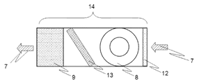
- FIG. 4 is a configuration diagram illustrating an example of the air conditioner 14 on which the humidifying device 9 according to the first embodiment is mounted.
- the air conditioner 14 including the humidifier 9 according to the first embodiment includes a humidifier 9 having a blower 8, a filter 12, and a heat exchanger 13.
- the humidifying device 9 is arranged on the leeward side of the heat exchanger 13, and humidifies the space by ventilating the air 7 heat-exchanged by the heat exchanger 13. (Operation of humidifier)
- FIGS. 1, 2, 3, and 4 the operation of the humidifier 9 according to the first embodiment and the air conditioner 14 including the humidifier 9 will be described with reference to FIGS. 1, 2, 3, and 4.
- the humidified water 1 stored in the supply unit 2 is conveyed to the nozzle 3.
- the humidified water 1 is dropped from the upper end on the windward side of the water absorbent humidifier 4 toward the water absorbent humidifier 4, whereby the humidified water 1 is removed from the water absorbent humidifier 4.
- the water-absorbing humidifier 4 has a capillary force and can utilize the gravity of the humidifying water 1. For this reason, the humidified water 1 is diffused into the water absorbent humidifier 4 through the gap 10 of the water absorbent humidifier 4.
- the air 7 flows from the blower 8 in parallel with the surface of the water absorbent humidifier 4 from one end on the windward side of the water absorbent humidifier 4 to the other end on the leeward side.
- the space where the material 4 is juxtaposed is ventilated. With this configuration, the air 7 is in gas-liquid contact with the surface of the water-absorbing humidifier 4, and the humidified water 1 is evaporated to humidify the space.
- FIG. 5 is a schematic diagram showing a humidification mechanism. The humidification mechanism from the water absorbing humidifier 4 will be described with reference to FIG.
- Diffusion of water vapor from the water-absorbing humidifying element 4 comprising humidifying water 1 into the air is governed by the diffusion rate N a.
- the diffusion coefficient is D e
- the moisture concentration (water content) in the air 7 is C a
- the moisture concentration (water content) in the water-absorbing humidifying material 4 is C o
- the saturated water vapor layer thickness is ⁇ .
- the diffusion rate N a is given by equation (1).
- N a D e ⁇ (C o ⁇ C a ) / ⁇ (1)
- Equation (2) When the boundary layer equation shown in Equation (2) is referred to, the saturated boundary layer thickness ⁇ of water vapor decreases as the wind speed U of the air 7 increases, so that the equation (1) increases as the wind velocity U of the air 7 increases.
- diffusion rate N a is increased as indicated by, humidification efficiency can be improved.
- the saturated boundary film layer thickness ⁇ of the water-absorbing humidifier 4 on the one end side on the windward side with respect to the airflow direction of the air 7 is the thinnest, one end including the plane portion and one end side on the windward side of the water-absorbing humidifier 4 High humidification performance is exhibited on the side. However, on this one end side, compared with the other end side, the humidification performance is higher, so the vaporization evaporation rate is also higher, and this is the place where the precipitation of scale is most promoted.
- the humidifying performance when the water absorbing humidifier 4 is provided with the opening 5 will be described.
- FIG. 6 the result of the humidification performance at the time of providing the circular opening part 5 in the flat resin humidification material 100 is shown.
- the resin humidifier is made of polypropylene. Evaluation conditions are as follows: flat plate-shaped resin humidifier 100 having a height of 170 mm, a depth of 30 mm, and a thickness of 1 mm; and a circular hole with a diameter of 0.95 mm in plate-shaped resin humidifier 100 at a pitch of 3 mm in FIG.
- FIG. 6 shows the results normalized by the humidifying performance of the flat resin humidifier 100.
- the humidifying performance was improved by 10% as compared with the humidifying performance 100% using the resin humidifying material 100 without the opening.
- the resin humidifying material 102 with the opening B was used, the humidifying performance was improved by 26% as compared with the humidifying performance 100% using the resin humidifying material 100 without the opening.
- the opening A of the resin humidifying material 101 and the opening B of the resin humidifying material 102 were observed with a microscope, a water film was formed in the opening A of the resin humidifying material 101.
- the opening 5 of the resin humidifying material with the opening B102 of the resin humidifying material 102 penetrated without forming a water film due to the influence of the surface tension of water.
- the surface area of the resin humidifier 102 with the opening B that has penetrated is increased by 10% compared to the surface area of the flat resin humidifier 100 without an opening, It was an increase of 26%.
- the opening 5 of the water-absorbing humidifier 4 containing the humidifying water 1 penetrates, the air 7 flowing in the vicinity of the water-absorbing humidifier 4 flows into and out of the opening 5. It was found that the turbulence is caused by the presence of the gas and the evaporation rate (mass transfer) is improved.
- the air conditioner 14 provided with the humidifying device 9 draws air 7 into the air conditioner 14 by the blower 8 as shown in FIG. Since the air 7 contains fine particles, the fine particles are collected by the filter 12, and the air 7 is heated or cooled by the heat exchanger 13, and is passed through the humidifier 9 to be humidified.
- the air-humidifying humidifier 4 having a low humidifying efficiency is unevenly distributed in the plane portion on the lee side.
- the humidification efficiency of the water-absorbing humidifier 4 can be made uniform.
- a load is applied not only to one end side including the leeward plane portion and one end side, but also to the other end side including the leeward plane portion and the other end side where the scale is deposited. Therefore, it is possible to provide the humidifier 9 that can increase the frequency of replacement of the water-absorbing humidifier 4 and the air conditioner 14 including the humidifier 9 while increasing the humidification performance.
- Embodiment 2 FIG. The humidifying device 9 according to the second embodiment and the air conditioner 14 provided with the humidifying device 9 will be described with a focus on differences from the first embodiment.
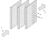
- FIG. 7 is a configuration diagram of the water-absorbing humidifying material 4 related to the humidifying device 9 according to Embodiment 2 of the present invention.
- FIG. 7 shows that the opening 5 that opens in the thickness direction (short axis direction) of the water-absorbing humidifier 4 is 2 on the other end side including the other end side on the leeward side and the plane portion with respect to the direction of air 7 flow.
- a plurality of rows are arranged to form three rows instead of rows.
- Other configurations are the same as those in FIG.
- the most dry air 7 is passed through one end of the water-absorbing humidifier 4 on the windward side.
- the humidifying performance per area in the flat part of the water becomes higher, the moisture concentration (water content) contained in the air 7 in the vicinity of the interface of the water-absorbing humidifier 4 increases with the humidifying effect as it becomes leeward.
- the humidification performance per area in the plane part on the leeward side is lowered. For this reason, a scale component tends to precipitate on the leeward side, and the amount of precipitation decreases as the leeward side is reached.
- the humidification performance per area on the other end side including the leeward plane portion and the other end side of the water absorbent humidifier 4 is improved, and the humidification performance and vaporization evaporation rate of the water absorbent humidifier 4 are uniform as a whole. Therefore, the plurality of openings 5 are arranged so that the distribution density of the openings 5 is increased on the leeward side of the water-absorbing humidifier 4.
- the openings 5 may be arranged in a lattice shape as shown in FIG. 7 or may be arranged in a staggered manner. Moreover, you may arrange
- the supply unit 2, the nozzle 3, the water-absorbing / humidifying material 4, the blower 8, and the drain pan 6 may be fixed by a predetermined support or the like.
- the structure of this support body is not specifically limited, What is necessary is just to select suitably according to the use of the humidification apparatus 9. FIG.
- the operation of the humidifier 9 and the air conditioner 14 provided with the humidifier 9 according to the second embodiment is the same as that of the first embodiment, and is therefore omitted.
- the configuration in which the distribution density of the openings 5 is reduced on the leeward side of the water-absorbing humidifier 4 and is increased on the leeward side so that conventionally, the humidification performance per area and the evaporation rate are increased.
- the humidification performance and vaporization evaporation rate in the low leeward region can be increased. Therefore, the scale that has been locally deposited on the leeward plane portion and one end side of the water-absorbing humidifier 4 can be deposited also on the leeward side.
- the surface load can be made as uniform as possible, and the exchange cycle of the water-absorbing humidifier 4 can be lengthened.
- Embodiment 3 The humidifier 9 according to the third embodiment and the air conditioner 14 provided with the humidifier 9 will be described focusing on the differences from the first embodiment.
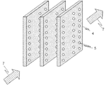
- FIG. 8 is a configuration diagram of the water-absorbing humidifier 4 related to the humidifying device 9 according to Embodiment 3 of the present invention.
- a plurality of openings 5 are arranged so that the arrangement interval of the openings 5 provided adjacent to the ventilation direction is increased on one end side of the water-absorbing humidifier 4 and decreased on the other end side. That is, the interval between the openings 5 adjacent on the other end side among the plurality of openings 5 is configured to be shorter than the interval between the openings 5 adjacent on the one end side.
- Evaporation rate is improved by air 7 flowing into and out of the opening 5 of the water-absorbing humidifier 4.
- the interval between the adjacent openings 5 on the leeward side is set to the adjacent openings on the leeward side. It is shorter than the arrangement interval of 5.
- the openings 5 may be arranged in a grid pattern or in a staggered pattern. Moreover, you may arrange
- the supply unit 2, the nozzle 3, the water-absorbing / humidifying material 4, the blower 8, and the drain pan 6 in Embodiment 3 may be fixed by a predetermined support body or the like.
- the structure of this support body is not specifically limited, What is necessary is just to select suitably according to the use of the humidification apparatus 9. FIG.
- the arrangement of the openings 5 adjacent to each other on the windward side of the water-absorbing humidifying material 4 is increased and decreased on the leeward side, so that conventionally, humidification performance per area and vaporization evaporation are achieved.
- the humidification performance and vaporization evaporation rate in the leeward region where the rate is low can be increased. Therefore, the scale that has been locally deposited on the leeward plane portion and one end side of the water-absorbing humidifier 4 can be deposited also on the leeward side.
- the surface load can be made as uniform as possible, and the exchange cycle of the water-absorbing humidifier 4 can be lengthened.
- Embodiment 4 The humidifier 9 according to the fourth embodiment and the air conditioner 14 provided with the humidifier 9 will be described with a focus on differences from the first embodiment.
- FIG. 9 is a configuration diagram of the water-absorbing humidifier 4 related to the humidifying device 9 according to Embodiment 4 of the present invention.
- FIG. 9 shows that the opening area of the plurality of openings 5 arranged in the ventilation direction increases from one end side to the other end side of the water absorbent humidifier 4, that is, as the air 7 moves from the upwind side to the downwind side. It is comprised so that it may become.
- the opening area of one opening 5 located on the other end side is configured to be larger than the opening area of one opening 5 located on one end side.
- Evaporation rate is improved by air 7 flowing into and out of the opening 5 of the water-absorbing humidifier 4.
- the opening area of the opening 5 is larger, the air 7 flowing into the opening 5 is more disturbed, so that the evaporation rate is improved. Therefore, in order to improve the leeward humidification performance and vaporization evaporation rate of the water absorbent humidifier 4 having a low humidification performance per area and vaporization evaporation rate, the opening of the opening 5 opened in the thickness direction of the water absorbent humidification material 4
- the area of the water-absorbing humidifier 4 is such that the opening area increases from the windward side to the leeward side along the ventilation direction of the air 7 from one end side to the other end side.
- the openings 5 may be arranged in a grid pattern or in a staggered pattern. Moreover, you may arrange
- the supply unit 2, the nozzle 3, the water-absorbing humidifier 4, the blower 8, and the drain pan 6 may be fixed by a predetermined support or the like.
- the structure of this support body is not specifically limited, What is necessary is just to select suitably according to the use of the humidification apparatus 9. FIG.
- the opening area of the opening 5 arranged from the windward side to the leeward side of the water-absorbing humidifier 4 increases, humidification performance and vaporization per area are conventionally achieved.
- the humidification performance and vaporization evaporation rate in the leeward region where the evaporation rate was low can be increased. Therefore, the scale that has been locally deposited on the leeward plane portion and one end side of the water-absorbing humidifier 4 can be deposited also on the leeward side.
- the surface load can be made as uniform as possible, and the exchange cycle of the water-absorbing humidifier 4 can be lengthened.
Abstract
Priority Applications (5)
| Application Number | Priority Date | Filing Date | Title |
|---|---|---|---|
| CN201680080235.3A CN108603675A (zh) | 2016-02-09 | 2016-02-09 | 加湿装置以及空调 |
| PCT/JP2016/053822 WO2017138095A1 (fr) | 2016-02-09 | 2016-02-09 | Dispositif d'humidification et climatiseur |
| US16/072,250 US10746419B2 (en) | 2016-02-09 | 2016-02-09 | Humidifier and air-conditioning apparatus |
| DE112016006379.2T DE112016006379B4 (de) | 2016-02-09 | 2016-02-09 | Befeuchter und Klimaanlage |
| JP2016543211A JP6076553B1 (ja) | 2016-02-09 | 2016-02-09 | 加湿装置及び空気調和機 |
Applications Claiming Priority (1)
| Application Number | Priority Date | Filing Date | Title |
|---|---|---|---|
| PCT/JP2016/053822 WO2017138095A1 (fr) | 2016-02-09 | 2016-02-09 | Dispositif d'humidification et climatiseur |
Publications (1)
| Publication Number | Publication Date |
|---|---|
| WO2017138095A1 true WO2017138095A1 (fr) | 2017-08-17 |
Family
ID=57981548
Family Applications (1)
| Application Number | Title | Priority Date | Filing Date |
|---|---|---|---|
| PCT/JP2016/053822 WO2017138095A1 (fr) | 2016-02-09 | 2016-02-09 | Dispositif d'humidification et climatiseur |
Country Status (5)
| Country | Link |
|---|---|
| US (1) | US10746419B2 (fr) |
| JP (1) | JP6076553B1 (fr) |
| CN (1) | CN108603675A (fr) |
| DE (1) | DE112016006379B4 (fr) |
| WO (1) | WO2017138095A1 (fr) |
Cited By (2)
| Publication number | Priority date | Publication date | Assignee | Title |
|---|---|---|---|---|
| JP2020125870A (ja) * | 2019-02-04 | 2020-08-20 | 三菱電機株式会社 | 加湿素子、加湿装置、空気調和機および換気装置 |
| WO2023021552A1 (fr) * | 2021-08-16 | 2023-02-23 | 三菱電機株式会社 | Élément d'humidification, dispositif d'humidification, dispositif de ventilation et climatiseur |
Families Citing this family (3)
| Publication number | Priority date | Publication date | Assignee | Title |
|---|---|---|---|---|
| JP2019007664A (ja) * | 2017-06-23 | 2019-01-17 | 木村工機株式会社 | 水膜気化式加湿器 |
| DE102018007981B3 (de) * | 2018-10-10 | 2020-03-12 | W. O. M. World of Medicine GmbH | Wasserreservoir für eine Vorrichtung zur Gasbefeuchtung in der Laparoskopie |
| US10955156B1 (en) * | 2019-12-11 | 2021-03-23 | Sten Kreuger | Air conditioning and humidity control system and methods of making and using the same |
Citations (7)
| Publication number | Priority date | Publication date | Assignee | Title |
|---|---|---|---|---|
| JPH04320743A (ja) * | 1991-04-22 | 1992-11-11 | Daikin Ind Ltd | 自然蒸発式加湿器 |
| JPH0632922U (ja) * | 1992-09-25 | 1994-04-28 | 石川島芝浦機械株式会社 | 冷風扇 |
| JPH07269915A (ja) * | 1994-03-29 | 1995-10-20 | Japan Gore Tex Inc | 加湿ユニット |
| JP2007255808A (ja) * | 2006-03-24 | 2007-10-04 | Toyota Motor Corp | 加湿装置および燃料電池システム |
| JP2008103115A (ja) * | 2006-10-17 | 2008-05-01 | Nissan Motor Co Ltd | 燃料電池用加湿装置 |
| JP2012013247A (ja) * | 2010-06-29 | 2012-01-19 | Mitsubishi Electric Corp | 加湿器 |
| JP2012093059A (ja) * | 2010-10-28 | 2012-05-17 | Mitsubishi Materials Corp | 蒸発板 |
Family Cites Families (47)
| Publication number | Priority date | Publication date | Assignee | Title |
|---|---|---|---|---|
| US654725A (en) * | 1898-04-21 | 1900-07-31 | Gustavus F Swift | Air-cooling apparatus. |
| US684217A (en) * | 1900-07-30 | 1901-10-08 | Gustavus F Swift | Air-cooling apparatus. |
| DE19910441C1 (de) * | 1999-03-10 | 2000-06-21 | Fraunhofer Ges Forschung | Luftbefeuchtung |
| US1283950A (en) * | 1917-02-17 | 1918-11-05 | John W Stiefel | Radiator for automobiles. |
| US1903250A (en) * | 1930-11-11 | 1933-03-28 | Tenney Dwight | Air conditioning apparatus |
| US1965255A (en) * | 1932-07-25 | 1934-07-03 | Andrew J Peabody | Air cooling device |
| US2099009A (en) * | 1935-11-13 | 1937-11-16 | Walter H Finley | Humidifying system and apparatus |
| US2161834A (en) * | 1936-12-09 | 1939-06-13 | Utica Radiator Corp | Air conditioning apparatus |
| US2204016A (en) * | 1937-06-25 | 1940-06-11 | Parks Cramer Co | Ventilating and humidifying system |
| US2251734A (en) * | 1939-07-20 | 1941-08-05 | Fuld | Diffusion and drip apparatus |
| US2326089A (en) * | 1941-07-30 | 1943-08-03 | Richard C Wittman | Humidifier |
| GB690737A (en) * | 1949-09-24 | 1953-04-29 | Wilhelm Otte | An improved plate-type apparatus for the cooling of liquids such as water, by means of air |
| US3378238A (en) * | 1965-07-15 | 1968-04-16 | Robert S. Babington | Porous block humidification |
| US3523681A (en) * | 1968-09-12 | 1970-08-11 | Richard C Jaye | Evaporator unit |
| US3722838A (en) * | 1969-12-22 | 1973-03-27 | J Swimmer | Humidifier |
| BE758570A (fr) * | 1970-11-06 | 1971-04-16 | Lefebvre Simon | Procede et appareillage pour la mise en contact de fluides et le transfert de matiere et de chaleur entre ceux-ci. |
| US4389352A (en) * | 1982-03-12 | 1983-06-21 | Acme Engineering & Manufacturing Corporation | Cooling pad support assembly |
| DK0504205T3 (da) * | 1989-12-08 | 1994-09-26 | Skandinavisk Miljo System As | Luftbefugtningsapparat |
| JPH03230037A (ja) | 1990-02-06 | 1991-10-14 | Matsushita Seiko Co Ltd | 加湿装置 |
| CN2169071Y (zh) | 1993-09-09 | 1994-06-15 | 王平智 | 湿帘 |
| CA2158417C (fr) * | 1995-02-17 | 1998-12-29 | Hisao Yokoya | Humidificateur |
| US6669626B1 (en) * | 1999-12-23 | 2003-12-30 | Hill-Rom Services, Inc. | Humidifier for a patient support apparatus |
| US6550748B2 (en) * | 2001-05-29 | 2003-04-22 | Emerson Electric Co. | Dry out mechanism for humidifier |
| JP2003230037A (ja) | 2002-02-04 | 2003-08-15 | Fuminori Suzuki | パソコンカメラ |
| US20050133942A1 (en) * | 2003-12-19 | 2005-06-23 | Rps Products, Inc. | Cartridge humidifier |
| US7513126B2 (en) * | 2005-01-25 | 2009-04-07 | Boland David V | Outdoor cooling device |
| CN2854431Y (zh) * | 2006-01-06 | 2007-01-03 | 保能科技股份有限公司 | 透气式液体挥发装置 |
| TW200743247A (en) * | 2006-05-04 | 2007-11-16 | Ind Tech Res Inst | External gas humidifying apparatus of fuel cell |
| US7931991B2 (en) * | 2006-12-26 | 2011-04-26 | Canon Kabushiki Kaisha | Fuel cell |
| JP4992458B2 (ja) * | 2007-02-19 | 2012-08-08 | パナソニック株式会社 | 気化フィルタおよび加湿装置 |
| US8550075B2 (en) * | 2007-06-28 | 2013-10-08 | Resmed Limited | Removable and/or replaceable humidifier |
| US20100207286A1 (en) * | 2009-02-18 | 2010-08-19 | Jursich Donald N | Humidifier with adjustable air flow |
| JP4818399B2 (ja) * | 2009-06-15 | 2011-11-16 | 三菱電機株式会社 | 静電霧化装置及び空気調和機 |
| JP2011062816A (ja) | 2009-09-15 | 2011-03-31 | Dynic Corp | 吸放湿用材料 |
| MY165944A (en) * | 2009-10-09 | 2018-05-18 | Philip Morris Products Sa | Aerosol generator including multi-component wick |
| EP2667919B1 (fr) * | 2011-01-24 | 2021-05-26 | ResMed Pty Ltd | Humidificateur |
| CA2738326A1 (fr) * | 2011-04-26 | 2012-10-26 | Jeri Rodrigs | Humidificateur pour conduite de ventilation d'une piece (alias rumidifier) |
| WO2013031568A1 (fr) * | 2011-08-29 | 2013-03-07 | 三菱電機株式会社 | Humidificateur et procédé d'humidification |
| US20130106004A1 (en) * | 2011-11-01 | 2013-05-02 | William C. Stumphauzer | Humidifier assembly |
| US9285133B2 (en) * | 2012-01-21 | 2016-03-15 | Air System Components, Inc. | Air humidification system |
| US8943851B2 (en) * | 2012-02-17 | 2015-02-03 | United Technologies Corporation | Evaporative cooler including one or more rotating cooler louvers |
| WO2014045609A1 (fr) * | 2012-09-18 | 2014-03-27 | 三菱電機株式会社 | Humidificateur et climatiseur équipé d'un humidificateur |
| CN104641182B (zh) * | 2012-09-20 | 2017-05-17 | 三菱电机株式会社 | 加湿器、加湿材料的亲水化处理方法 |
| JP6053595B2 (ja) * | 2013-04-03 | 2016-12-27 | 三菱電機株式会社 | 加湿器 |
| DE112014002085B4 (de) * | 2013-04-22 | 2021-02-04 | Mitsubishi Electric Corporation | Befeuchter und Befeuchter aufweisende Klimaanlage |
| US10871296B2 (en) * | 2013-09-18 | 2020-12-22 | Mitsubishi Electric Corporation | Humidifier and air-conditioning apparatus including humidifier |
| US10202511B2 (en) * | 2013-12-18 | 2019-02-12 | Mitsubishi Electric Corporation | Hydrophilic coating film, method for producing same, humidification element, and humidification device |
-
2016
- 2016-02-09 JP JP2016543211A patent/JP6076553B1/ja active Active
- 2016-02-09 WO PCT/JP2016/053822 patent/WO2017138095A1/fr active Application Filing
- 2016-02-09 US US16/072,250 patent/US10746419B2/en active Active
- 2016-02-09 DE DE112016006379.2T patent/DE112016006379B4/de active Active
- 2016-02-09 CN CN201680080235.3A patent/CN108603675A/zh active Pending
Patent Citations (7)
| Publication number | Priority date | Publication date | Assignee | Title |
|---|---|---|---|---|
| JPH04320743A (ja) * | 1991-04-22 | 1992-11-11 | Daikin Ind Ltd | 自然蒸発式加湿器 |
| JPH0632922U (ja) * | 1992-09-25 | 1994-04-28 | 石川島芝浦機械株式会社 | 冷風扇 |
| JPH07269915A (ja) * | 1994-03-29 | 1995-10-20 | Japan Gore Tex Inc | 加湿ユニット |
| JP2007255808A (ja) * | 2006-03-24 | 2007-10-04 | Toyota Motor Corp | 加湿装置および燃料電池システム |
| JP2008103115A (ja) * | 2006-10-17 | 2008-05-01 | Nissan Motor Co Ltd | 燃料電池用加湿装置 |
| JP2012013247A (ja) * | 2010-06-29 | 2012-01-19 | Mitsubishi Electric Corp | 加湿器 |
| JP2012093059A (ja) * | 2010-10-28 | 2012-05-17 | Mitsubishi Materials Corp | 蒸発板 |
Cited By (3)
| Publication number | Priority date | Publication date | Assignee | Title |
|---|---|---|---|---|
| JP2020125870A (ja) * | 2019-02-04 | 2020-08-20 | 三菱電機株式会社 | 加湿素子、加湿装置、空気調和機および換気装置 |
| JP7236872B2 (ja) | 2019-02-04 | 2023-03-10 | 三菱電機株式会社 | 加湿素子、加湿装置、空気調和機および換気装置 |
| WO2023021552A1 (fr) * | 2021-08-16 | 2023-02-23 | 三菱電機株式会社 | Élément d'humidification, dispositif d'humidification, dispositif de ventilation et climatiseur |
Also Published As
| Publication number | Publication date |
|---|---|
| US20190032934A1 (en) | 2019-01-31 |
| JP6076553B1 (ja) | 2017-02-08 |
| CN108603675A (zh) | 2018-09-28 |
| DE112016006379B4 (de) | 2020-07-16 |
| DE112016006379T5 (de) | 2018-10-25 |
| US10746419B2 (en) | 2020-08-18 |
| JPWO2017138095A1 (ja) | 2018-02-15 |
Similar Documents
| Publication | Publication Date | Title |
|---|---|---|
| JP6076553B1 (ja) | 加湿装置及び空気調和機 | |
| JP5955395B2 (ja) | 加湿装置及び加湿装置を備えた空気調和機 | |
| JP6080965B2 (ja) | 加湿装置、及び加湿装置を備えた空気調和機 | |
| JP6165328B2 (ja) | 加湿装置及び加湿装置付きの空気調和機 | |
| JP5989236B2 (ja) | 加湿装置及び加湿装置を備えた空気調和機 | |
| JP6076544B2 (ja) | 加湿装置、及び加湿装置を備えた空気調和機 | |
| JP2014202438A (ja) | 加湿器 | |
| JP2007139251A (ja) | 加湿装置 | |
| JP2947347B1 (ja) | 空気調和機用熱交換コイル | |
| JP6049909B2 (ja) | 加湿器 | |
| JP6890666B2 (ja) | 加湿体ユニット及び加湿装置 | |
| JP6831160B2 (ja) | 水噴霧型加湿装置 | |
| JP5137878B2 (ja) | 気液接触材料及び該気液接触材料を備えた汚染物質除去装置 | |
| JP5885653B2 (ja) | 加湿装置 | |
| JP2021156551A (ja) | 空気清浄装置 |
Legal Events
| Date | Code | Title | Description |
|---|---|---|---|
| ENP | Entry into the national phase |
Ref document number: 2016543211 Country of ref document: JP Kind code of ref document: A |
|
| 121 | Ep: the epo has been informed by wipo that ep was designated in this application |
Ref document number: 16889797 Country of ref document: EP Kind code of ref document: A1 |
|
| WWE | Wipo information: entry into national phase |
Ref document number: 112016006379 Country of ref document: DE |
|
| 122 | Ep: pct application non-entry in european phase |
Ref document number: 16889797 Country of ref document: EP Kind code of ref document: A1 |