WO2017134884A1 - 内視鏡用撮像装置 - Google Patents
内視鏡用撮像装置 Download PDFInfo
- Publication number
- WO2017134884A1 WO2017134884A1 PCT/JP2016/082325 JP2016082325W WO2017134884A1 WO 2017134884 A1 WO2017134884 A1 WO 2017134884A1 JP 2016082325 W JP2016082325 W JP 2016082325W WO 2017134884 A1 WO2017134884 A1 WO 2017134884A1
- Authority
- WO
- WIPO (PCT)
- Prior art keywords
- metal
- exterior member
- fixing
- exterior
- endoscope
- Prior art date
Links
- 0 C*(*)CC1*(C)C(C(CC=N*)C2)IC2C1 Chemical compound C*(*)CC1*(C)C(C(CC=N*)C2)IC2C1 0.000 description 1
Images


Classifications
-
- A—HUMAN NECESSITIES
- A61—MEDICAL OR VETERINARY SCIENCE; HYGIENE
- A61B—DIAGNOSIS; SURGERY; IDENTIFICATION
- A61B1/00—Instruments for performing medical examinations of the interior of cavities or tubes of the body by visual or photographical inspection, e.g. endoscopes; Illuminating arrangements therefor
- A61B1/04—Instruments for performing medical examinations of the interior of cavities or tubes of the body by visual or photographical inspection, e.g. endoscopes; Illuminating arrangements therefor combined with photographic or television appliances
- A61B1/05—Instruments for performing medical examinations of the interior of cavities or tubes of the body by visual or photographical inspection, e.g. endoscopes; Illuminating arrangements therefor combined with photographic or television appliances characterised by the image sensor, e.g. camera, being in the distal end portion
-
- A—HUMAN NECESSITIES
- A61—MEDICAL OR VETERINARY SCIENCE; HYGIENE
- A61B—DIAGNOSIS; SURGERY; IDENTIFICATION
- A61B1/00—Instruments for performing medical examinations of the interior of cavities or tubes of the body by visual or photographical inspection, e.g. endoscopes; Illuminating arrangements therefor
- A61B1/00064—Constructional details of the endoscope body
- A61B1/0011—Manufacturing of endoscope parts
-
- A—HUMAN NECESSITIES
- A61—MEDICAL OR VETERINARY SCIENCE; HYGIENE
- A61B—DIAGNOSIS; SURGERY; IDENTIFICATION
- A61B1/00—Instruments for performing medical examinations of the interior of cavities or tubes of the body by visual or photographical inspection, e.g. endoscopes; Illuminating arrangements therefor
- A61B1/04—Instruments for performing medical examinations of the interior of cavities or tubes of the body by visual or photographical inspection, e.g. endoscopes; Illuminating arrangements therefor combined with photographic or television appliances
- A61B1/042—Instruments for performing medical examinations of the interior of cavities or tubes of the body by visual or photographical inspection, e.g. endoscopes; Illuminating arrangements therefor combined with photographic or television appliances characterised by a proximal camera, e.g. a CCD camera
-
- A—HUMAN NECESSITIES
- A61—MEDICAL OR VETERINARY SCIENCE; HYGIENE
- A61B—DIAGNOSIS; SURGERY; IDENTIFICATION
- A61B1/00—Instruments for performing medical examinations of the interior of cavities or tubes of the body by visual or photographical inspection, e.g. endoscopes; Illuminating arrangements therefor
- A61B1/04—Instruments for performing medical examinations of the interior of cavities or tubes of the body by visual or photographical inspection, e.g. endoscopes; Illuminating arrangements therefor combined with photographic or television appliances
- A61B1/045—Control thereof
-
- A—HUMAN NECESSITIES
- A61—MEDICAL OR VETERINARY SCIENCE; HYGIENE
- A61B—DIAGNOSIS; SURGERY; IDENTIFICATION
- A61B1/00—Instruments for performing medical examinations of the interior of cavities or tubes of the body by visual or photographical inspection, e.g. endoscopes; Illuminating arrangements therefor
- A61B1/12—Instruments for performing medical examinations of the interior of cavities or tubes of the body by visual or photographical inspection, e.g. endoscopes; Illuminating arrangements therefor with cooling or rinsing arrangements
- A61B1/128—Instruments for performing medical examinations of the interior of cavities or tubes of the body by visual or photographical inspection, e.g. endoscopes; Illuminating arrangements therefor with cooling or rinsing arrangements provided with means for regulating temperature
-
- G—PHYSICS
- G02—OPTICS
- G02B—OPTICAL ELEMENTS, SYSTEMS OR APPARATUS
- G02B23/00—Telescopes, e.g. binoculars; Periscopes; Instruments for viewing the inside of hollow bodies; Viewfinders; Optical aiming or sighting devices
- G02B23/24—Instruments or systems for viewing the inside of hollow bodies, e.g. fibrescopes
- G02B23/2476—Non-optical details, e.g. housings, mountings, supports
- G02B23/2484—Arrangements in relation to a camera or imaging device
-
- G—PHYSICS
- G03—PHOTOGRAPHY; CINEMATOGRAPHY; ANALOGOUS TECHNIQUES USING WAVES OTHER THAN OPTICAL WAVES; ELECTROGRAPHY; HOLOGRAPHY
- G03B—APPARATUS OR ARRANGEMENTS FOR TAKING PHOTOGRAPHS OR FOR PROJECTING OR VIEWING THEM; APPARATUS OR ARRANGEMENTS EMPLOYING ANALOGOUS TECHNIQUES USING WAVES OTHER THAN OPTICAL WAVES; ACCESSORIES THEREFOR
- G03B17/00—Details of cameras or camera bodies; Accessories therefor
- G03B17/55—Details of cameras or camera bodies; Accessories therefor with provision for heating or cooling, e.g. in aircraft
-
- H—ELECTRICITY
- H04—ELECTRIC COMMUNICATION TECHNIQUE
- H04N—PICTORIAL COMMUNICATION, e.g. TELEVISION
- H04N23/00—Cameras or camera modules comprising electronic image sensors; Control thereof
- H04N23/50—Constructional details
- H04N23/555—Constructional details for picking-up images in sites, inaccessible due to their dimensions or hazardous conditions, e.g. endoscopes or borescopes
-
- H—ELECTRICITY
- H04—ELECTRIC COMMUNICATION TECHNIQUE
- H04N—PICTORIAL COMMUNICATION, e.g. TELEVISION
- H04N23/00—Cameras or camera modules comprising electronic image sensors; Control thereof
- H04N23/56—Cameras or camera modules comprising electronic image sensors; Control thereof provided with illuminating means
Definitions
- the present invention relates to an endoscope imaging apparatus including an exterior member that is airtightly held and has a single layer of metal.
- An endoscope imaging apparatus captures an image of a test site in a subject and outputs the captured image of the test site to a monitor, for example, on the proximal end side of an insertion portion of the endoscope A configuration that can be connected to an eyepiece provided (hereinafter referred to as an eyepiece) is well known.
- an internal unit including an imaging unit including an imaging element, an objective optical system, and the like in an endoscope imaging device is provided in an exterior member of the endoscope imaging device.
- the high temperature and high pressure steam also enters the exterior member.
- the imaging unit touches the high-temperature and high-pressure steam, the imaging device may break down or the objective optical system may become cloudy. Need to be provided.
- Japanese Unexamined Patent Publication No. 2013-56003 discloses that an endoscope imaging device mounted on an eyepiece of an endoscope is made of a resin in an exterior member made of a metal such as stainless steel. An airtight case is provided, and an internal unit including the imaging unit is sealed in the airtight case. Thus, a configuration of an endoscope imaging device that protects the imaging unit from high-temperature and high-pressure steam that has entered the exterior member is disclosed.
- the exterior member is made of a heavy metal such as stainless steel and has a two-layered airtight case in the exterior member. It has the case structure. For this reason, there existed a problem that the weight of the imaging device for endoscopes became heavy.
- the exterior member is made of, for example, titanium, which is lighter than stainless steel, and the exterior member itself has an airtight structure, so that the exterior member also serves as an airtight case.
- the exterior member also serves as an airtight case.
- the internal unit is fixed to a screw hole or the like in which at least one fixing part of the holding member made of metal holding the internal unit is provided on the inner surface of the internal unit.
- the structure fixed with fixing members, such as a screw, with respect to a part can be considered.
- the reason why the internal unit is directly fixed to the inner surface of the exterior member is that it is necessary to fix the internal unit with high positional accuracy in the exterior member in order to improve the optical characteristics of the objective optical system provided in the internal unit. .
- the holding member is made of metal
- the image pickup device of the internal unit is a heating element that generates heat as it is driven. For this reason, the temperature in the exterior member having an airtight structure rises due to the heat of the image sensor as the image sensor is driven. This is because in order to prevent the image sensor from being damaged due to the temperature rise, it is necessary to transfer the heat of the image sensor to the exterior member via the holding member and to dissipate the heat to the outside of the exterior member.
- the present invention has been made in view of the above problems, and the fixing portion of the internal unit of the single-layer exterior member that also serves as an airtight case is locally heated by the heat of the heating element in the exterior member.
- An object of the present invention is to provide an endoscope imaging apparatus having a configuration that can prevent this.
- An endoscope imaging apparatus includes an exterior member configured to hold an interior hermetically and configured in a single layer from a metal, and an internal unit provided in the interior of the exterior member. And a holding member made of metal having at least one fixing portion that is provided in the internal unit and holds the internal unit and fixes the internal unit to the inner surface of the exterior member, and the holding member And a heat insulating member made of a member having a lower thermal conductivity than that of a metal, provided between at least one of the fixing portion and the fixing portion of the inner surface of the exterior member.
- FIG. 4 and FIG. 5 are partial cross-sectional views showing an enlargement of a lower side fixing portion of the fixing frame.
- FIG. 9 The figure which shows schematically the structure of the modification of the exterior member of the internal unit of FIG. 3 with an exterior cover and a camera cable.
- the fragmentary sectional view which expands and shows the exterior cover of FIG. FIG. 9 is an enlarged partial cross-sectional view of the part surrounded by the line XI in FIG.
- sticker of FIG. 11 is provided
- the fragmentary sectional view which expands and shows roughly the periphery structure of the fixing screw for coupler parts of FIG.
- FIG. 1 is a diagram showing an outline of a configuration of an endoscope system including an endoscope imaging apparatus according to the present embodiment.
- an endoscope system 1 includes an endoscope 2, a camera head 3 that is an endoscope imaging device that can be connected to the endoscope 2, and illumination light to the endoscope 2. And a light source device 4 to be supplied.
- the endoscope system 1 also includes a camera control unit (CCU) 5 that performs signal processing on an image pickup signal from the camera head 3 and a monitor 6 that displays a video signal output from the CCU 5. ing.
- CCU camera control unit
- the endoscope 2 includes an elongated insertion portion 7, a gripping portion 8 having a larger diameter than the insertion portion 7 provided on the proximal end side of the insertion portion 7, and an eyepiece provided on the proximal end of the gripping portion 8
- the main part is comprised.
- one end of the light guide cable 10 detachably attached to the light source device 4 via the connector 11 is connectable to a base provided on the side portion of the grip portion 8 of the endoscope 2.
- the image in the subject illuminated by the illumination light is formed into an optical image on an objective optical system (not shown) provided at the distal end of the insertion portion 7, and the formed optical image is provided in the insertion portion 7.
- the light is incident on a lens provided in the eyepiece 9 through a relay lens (not shown).
- a relay lens not shown
- the camera head 3 can be connected to the eyepiece 9 of the endoscope 2.
- a camera cable 12 extends from the camera head 3, and an extended end of the camera cable 12 is detachable from the CCU 5 via a connector 13 provided at the extended end.
- the CCU 5 generates an image signal based on an imaging signal transmitted from the camera head 3 via the camera cable 12, and displays an image in the subject on the monitor 6 as an endoscopic image.
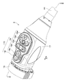
- FIGS. 2 is a perspective view showing the camera head of FIG. 1
- FIG. 3 is a partial sectional view of the camera head along the line III-III in FIG. 2
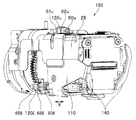
- FIG. 4 is a perspective view showing the internal unit of FIG. 5 is a perspective view of the internal unit in FIG. 3 as seen from a direction different from that in FIG. 4.
- the camera head 3 includes a coupler portion 15 and an exterior member 17 having a distal end fixed to the coupler portion 15 to constitute a main portion.
- the coupler unit 15 is a member to which the eyepiece 9 of the endoscope 2 is connected, and is fixed to the outer periphery on the distal end 17ak side of the exterior member 17 using a fixing screw 32. Yes.
- the exterior member 17 is made of a single layer made of metal while keeping the inside airtight, and includes a main cover 17a and a rear cover 17b fixed to the base end of the main cover 17a in a watertight and airtight manner by soldering, welding, or the like. It is composed of That is, the exterior member 17 also serves as an airtight case.
- titanium is mentioned, for example.
- a metal which comprises the exterior member 17 a lightweight and low thermal conductivity thing is desirable.
- any metal such as stainless steel may be used as long as it can be hermetically welded to prevent the high-temperature and high-pressure steam from entering the interior 17i in the autoclave process described above.
- one side surface of the main cover 17a specifically, the outer peripheral side surface in the upper part of the drawing shown in FIGS.
- the switch unit 170 is fixed along the longitudinal direction N of the camera head 3.
- the switch unit 170 includes a plurality of switch buttons 19 covered with a rubber cover or the like, and a switch button frame 18 for attaching the plurality of switch buttons 19 to the main cover 17a in a watertight manner.
- the plurality of switch buttons 19 adjusts the focus magnification by moving a part of a lens 30 (see FIG. 3), which will be described later, to adjust the focus by moving the lens 30 back and forth, or by moving a part of the lens 30 back and forth.
- the switch button frame 18 is made of a member having a lower thermal conductivity than metal, for example, a resin material, and covers the upper portion of the main cover 17a along the longitudinal direction N.
- an internal unit 150 shown in FIGS. 3 to 5 having an imaging unit 100 as a heating element is provided in an internal 17i hermetically sealed by an exterior member 17.
- the internal unit 150 is inserted into the interior 17i from the rear opening of the main cover 17a when the rear cover 17b is not fixed to the main cover 17a of the exterior member 17 when assembled.
- the main cover 17a is composed of one part. For this reason, compared with the case where it is composed of a plurality of parts, in the configuration in which each fixing portion 120u, 120r, 120l of the fixing frame 120 of the internal unit 150 is attached to and fixed to the fixing portion of the exterior member 17 described later, This is because the positional accuracy of the internal unit 150 is improved, so that the optical eccentricity of the lens 30 can be prevented.
- the imaging unit 100 includes a plurality of lenses 30, a lens frame 51 that holds the lenses 30, an imaging element 33, and electrical components such as various substrates, and the main part is configured.
- the plurality of lenses 30 are located in the distal end 17ak of the main cover 17a with respect to the observation window 31 that is airtightly fixed by solder or the like by metallizing the outer periphery. Opposite the longitudinal direction N.
- the observation window 31 is positioned facing the lens in the eyepiece 9 in the longitudinal direction N.
- a plurality of lenses 30 held by a lens frame 51 are provided behind the observation window 31 in the interior 17 i of the exterior member 17, and the imaging element 33 is positioned at the imaging position of the plurality of lenses 30. is doing.
- the lens frame 51 and the image sensor 33 are held by a fixed frame 120 that is a holding member provided between the lens frame 51 and the image sensor 33 in the longitudinal direction N.
- the fixed frame 120 holds the internal unit 150, and is made of metal in order to release heat from the image sensor 33.
- the fixing frame 120 has fixing portions 120u, 120r, and 120l for fixing the internal unit 150 to the inner surface 17n of the main cover 17a.
- the fixing part 120u is provided at the upper part in the figure, and the fixing part 120r is provided on the lower side and the right side in the figure when the observation window 31 is the front.
- the fixing part 120l is provided on the lower side and the left side in the figure when the observation window 31 is the front.
- the fixing portions 120u, 120r, and 120l are provided approximately every 120 ° in the circumferential direction of the internal unit 150.
- the fixed part of the fixed frame 120 may be plural other than three, or may be one.
- a fixing configuration to the inner surface 17n using the fixing portions 120u, 120r, and 120l of the fixing frame 120 will be described later.
- the fixing part 120u is referred to as an upper fixing part 120u
- the fixing parts 120r and 120l are referred to as lower fixing parts 120r and 120l.
- the internal unit 150 is not in contact with the inner surface 17 n of the exterior member 17 except for the fixing portions 120 u, 120 r, 120 l of the fixing frame 120 and the heat dissipation sheet 140 described later. It is provided as follows.
- the various substrates are electrically connected to a substrate 35 located behind the substrate folder 200 via a flexible substrate 138 bent in a U shape.
- the substrate folder 200 and the substrate 35 are fixed to the frame 28 fixed to the outer periphery of the fixed frame 120.
- a connector 38a of a flexible board 38 that is bent upside down from the flexible board 138 and is extended from the board 35 is electrically connected to the board 35.
- the connector 38 b provided at the extending end of the flexible substrate 38 is electrically connected to the substrate 320 provided to be inclined rearward of the substrate 35.
- a hermetic connector 160 fixed to the inner surface 17n at the end of the rear cover 17b by welding or the like is provided on the base end side of the substrate 320, and a substrate 45 is provided on the base end side of the hermetic connector 160. It has been.
- the hermetic connector 160 is provided with a plurality of conducting pins 42 penetrating the hermetic connector 160, and the substrate 320 and the substrate 45 are electrically connected by the conducting pins 42.
- a cable fixing frame 41 that is a base made of metal is connected to the proximal end side of the rear cover 17 b via a hermetic connector 160.
- the outer periphery on the base end side of the rear cover 17b, the outer periphery of the hermetic connector 160, and the outer periphery on the distal end side of the cable fixing frame 41 are covered with a heat sink 130 that is an exterior member external heat transfer member made of metal.
- the heat sink 130 is made of a material having better thermal conductivity than the rear cover 17b made of titanium, for example, a copper material.
- a spacer ring 179 is fixed to the base end of the cable fixing frame 41, and the distal end of the camera cable 12 is connected to the inner peripheral surface of the spacer ring 179.
- a plurality of electric cords made of a resin material having a lower thermal conductivity than the metal, for example, a resin material, is housed on the outer periphery of the metal conductor. It extends into the fixed frame 41 and is electrically connected to the substrate 45.
- the outer peripheral surface of the camera cable 12 is covered with a bend preventing 44 that prevents the camera cable 12 from being bent suddenly.
- a rear screw 50 is movably covered on the outer periphery of the bend stopper 44, and the front end side of the camera cable 12 is fixed to the cable fixing frame 41 in a watertight and airtight manner by the rear screw 50.
- An exterior cover 40 made of a resin material such as (registered trademark) or PEEK is provided.
- the heat radiating plate 110 that is a heat transfer member in the exterior member that extends from the fixed frame 120 to the region R1 covered by the exterior cover 40 in the interior 17i of the exterior member 17 is fixed to the fixed frame 120.
- the heat sink 110 is comprised from the metal.
- the heat radiating plate 110 extends from the fixed frame 120 to the inside of the rear cover 17b, as shown in FIGS. Has been issued.
- the heat radiating plate 110 is connected to the fixed frame 120 made of metal, so that the heat transferred from the image sensor 33 to the fixed frame 120 is further transferred to the rear of the internal unit 150. .
- a heat radiating sheet 140 made of a rubber-like (gel-like) sheet having a relatively high thermal conductivity is formed on the inner surface 17n of the rear cover 17b on the base end surface of the heat radiating plate 110. It is provided in surface contact with the inner surface 17n in a crushed state. Thereby, the heat of the heat dissipation sheet 140 is reliably transmitted to the rear cover 17b.
- the heat transferred from the image sensor 33 to the fixed frame 120 is transmitted to the heat sink 130 via the heat radiating plate 110, the heat radiating sheet 140, and the rear cover 17b, and then the conductor of the camera cable 12 via the cable fixing frame 41. Is transmitted to.
- the heat sink 130 is made of a metal having higher thermal conductivity than the rear cover 17b, the heat of the rear cover 17b is efficiently transmitted to the heat sink 130 without escaping to the outside.
- the exterior cover 40 covers the outer periphery of the rear cover 17b, the outer periphery of the heat sink 130, and the outer periphery of the proximal end side of the cable fixing frame 41, so that heat is externally transmitted from the rear cover 17b, the heat sink 130, and the cable fixing frame 41 each made of metal. To prevent direct heat dissipation. In other words, the exterior cover 40 prevents the operator from coming into direct contact with the rear cover 17b, the heat sink 130, and the cable fixing frame 41.
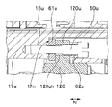
- FIG. 6 is an enlarged partial cross-sectional view showing an upper-side fixing portion of the fixing frame in FIG. 3
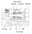
- FIG. 7 is an enlarged partial cross-sectional view showing a lower-side fixing portion of the fixing frame in FIGS. .
- the internal unit 150 is configured so that the upper side fixing portion 120u and the lower side fixing portions 120r and 120l of the fixing frame 120 are fixed to the inner surface 17n of the main cover 17a of the outer member 17 so 17i.
- a screw hole 16u as a fixing portion is formed on the inner surface 17n of the main cover 17a of the exterior member 17 at a position facing the upper side fixing portion 120u. .
- screw holes 16r and 16l as fixing portions are formed on the inner surface 17n of the main cover 17a at positions facing the lower side fixing portions 120r and 120l. .
- a through hole 120uh penetrating in the longitudinal direction N is formed in the upper fixing portion 120u.
- a screw 60u which is a fixing member inserted through the through hole 120uh, is screwed into the screw hole 16u via a metal washer 61u covered on the outer periphery of the screw 60u, so that the upper fixing portion 120u is brought into contact with the inner surface 17n. , Fixed through metal.
- the metal washer 61u is located between the upper side fixing portion 120u and the inner surface 17n.
- the fixed frame 120 is connected to the region R2 of the main cover 17a of the exterior member 17 covered with the switch button frame 18 made of the resin material of the switch unit 170, as shown in FIG.
- the heat transferred from the image sensor 33 to the fixed frame 120 is a region R2 covered by the switch button frame 18 in the main cover 17a of the exterior member 17 through the upper fixed portion 120u, the screw 60u, and the metal washer 61u. Is transmitted to.
- the switch button frame 18 covers the outer periphery of the upper side of the main cover 17a, thereby preventing heat from being directly radiated to the outside from the upper side of the main cover 17a. In other words, the switch button frame 18 prevents the operator from coming into direct contact with the upper side of the main cover 17a.
- through holes 120rh and 120lh penetrating in the longitudinal direction N are formed in the lower-side fixing portions 120r and 120l.
- Screws 60r and 60l which are fixing members inserted through the through holes 120rh and 120lh are screw holes 16r and 16r through washers 65r and 65l and bushes 66r and 66l which are heat insulating members coated on the outer periphery of the screws 60r and 60l.
- the lower-side fixing parts 120r and 120l are fixed to the inner surface 17n via washers 65r and 65l and bushes 66r and 66l.
- the washers 65r and 65l and the bushes 66r and 66l are composed of members having a lower thermal conductivity than metal.
- the washers 65r and 65l are located between the lower-side fixing portions 120r and 120l and the inner surface 17n.
- the lower-side fixing portions 120r and 120l made of metal have a structure that does not directly contact the inner surface 17n of the main cover 17a made of metal.
- the washers 65r and 65l and the bushes 66r and 66l are made of a member having a lower thermal conductivity than that of the metal, so that the heat transferred from the imaging element 33 to the fixed frame 120 is lower-side fixed portions 120r and 120l. This is a member that is transmitted to the main cover 17a of the exterior member 17 and prevents the vicinity of the screw holes 16r and 16l of the main cover 17a from being heated locally.
- the internal unit 150 is fixed to the screw holes 16u, 16r, and 16l of the inner surface 17n of the exterior member 17 using the screws 60u, 60r, and 60l.
- the side fixing parts 120r and 120l are configured such that the screws 60r and 60l are screwed into the screw holes 16r and 16l through the washers 65r and 65l and the bushes 66r and 66l. , 66l.
- the lower side fixing parts 120r and 120l are not directly in contact with the main cover 17a.
- the internal unit 150 is shown to be fixed to the inner surface 17n of the exterior member 17 in a non-contact manner except for the upper side fixing portion 120u, the lower side fixing portions 120r and 120l, and the heat dissipation sheet 140.
- the heat transferred from the image sensor 33 to the fixed frame 120 is transferred from the lower-side fixed portions 120r and 120l to the portions where the screw holes 16r and 16l of the main cover 17a are formed. Can be prevented by washers 65r and 65l and bushes 66r and 66l which are heat insulating members made of a resin material.
- the heat transferred from the image sensor 33 to the fixed frame 120 is transferred to the metal provided in the regions R1 and R2 connected to the fixed frame 120 and covered with the resin material. I showed.
- the heat radiating plate 110 extending to the region R1 is connected to the fixed frame 120, and the heat transferred from the imaging element 33 to the fixed frame 120 is the heat radiating plate 110, the heat radiating sheet 140, and the rear cover 17b. It is shown that it is transmitted to the heat sink 130 via the cable and then transmitted to the conductor of the camera cable 12 via the cable fixing frame 41. That is, it is shown that the signal is transmitted to the region 12 covered by the exterior cover 40 and then transmitted to the cable 12.
- the region R2 covered by the switch button frame 18 in the main cover 17a of the exterior member 17 is connected to the upper side fixing portion 120u of the fixed frame 120, and the heat transferred from the image sensor 33 to the fixed frame 120. Is transmitted to the region R2 covered by the switch button frame 18 in the main cover 17a of the exterior member 17 via the upper side fixing portion 120u, the screw 60u, and the metal washer 61u.
- the heat of the image sensor 33 that is, the heat of the inside 17i of the exterior member 17 is released to the non-contact metal by the operator located in the regions R1 and R2, and is radiated. It is difficult for heat to be transferred to the metal part in the camera head 3 that the operator directly contacts.
- the temperature of the interior 17i of the exterior member 17 can be reduced, and even if the exterior member 17 is made of metal, the temperature of the part of the exterior member 17 that the operator contacts or the other part of the camera head can be reduced. Can be reduced.
- FIG. 8 is a partial cross-sectional view showing a modified example of the shape of the upper fixed portion in the fixed frame of FIG.
- the internal unit 150 when the internal unit 150 is fixed to the inner surface 17n of the exterior member 17, the internal unit 150 can be fixed with as much positional accuracy as possible in order to prevent damage to the components of the internal unit 150 and improve the optical accuracy of the lens 30. A structure is desired.
- the internal unit 150 is preferably fixed at the center of gravity of the internal unit 150 with respect to the inner surface 17 n of the exterior member 17.
- the fixing portion of the internal unit 150 in the exterior member 17, that is, the internal unit 150 is fixed.
- the positions in the longitudinal direction N of the screw holes 16u, 16r, and 16l into which the screws 60u, 60r, and 60l are screwed are separated forward from the base end of the main cover 17a.
- the internal unit 150 is made to enter the inside from the opening at the base end of the main cover 17a, and after the fixing portions 120u, 120r, 120l are brought into contact with the fixing portions of the main cover 17a, It is difficult to screw the screws 60u, 60r, 60l into the screw holes 16u, 16r, 16l using a screwdriver or the like through the through holes 120uh, 120rh, 120lh formed in the fixing parts 120u, 120r, 120l. There is a possibility of dropping 60u, 60r, 60l.
- the screws 60u, 60r, 60l are inserted in advance into the through holes 120uh, 120rh, 120lh, and As described above, a configuration in which the outer circumferences of the screws 60u, 60r, and 60l are covered with the fall prevention washers 61u, 61r, and 61l is also conceivable.
- the washer 61 u, 61 r, 61 l abuts against the fixed portion on the inner surface 17 n of the exterior member 17, so that the contact position accuracy of the internal unit 150 decreases.
- the lens 30 of the internal unit 150 may be decentered.
- a slit 120us is provided at a substantially central position in the longitudinal direction N of the upper fixing portion 120u, and a metal washer 61u is provided in the slider 120us.
- the metal washer 61u can prevent the screw 60u from dropping off as in the conventional case, and the upper fixing portion 120u is in direct contact with the fixing portion on the inner surface 17n of the exterior member 17. For this reason, the internal unit 150 can be fixed with high positional accuracy and the assembly of the camera head 3 is improved.
- the screw 60u having a length where the head of the screw 60u is located near the base end of the main cover 17a is used, the screw 60u using a tool such as a screwdriver is screwed into the screw hole 16u. In addition to facilitating the operation, it is possible to improve the diffusibility of the heat transferred from the screw 60u to the screw 60u.
- the screw 60u is made of a material having high thermal conductivity and the screw 60u is covered with a cylindrical heat radiation material, or the screw 60u has a knurled head to increase the surface area of the screw 60u head.
- the diffusibility of the heat transmitted from the screw 60u to the screw 60u can be improved.
- the exterior member 17 is shown to be made of a metal such as titanium.
- the imaging unit 100 provided in the interior 17i of the main cover 17a of the exterior member 17 generates heat and is transferred to the main cover 17a, the portion of the main cover 17a in the vicinity of the imaging unit 100 is locally heated. There is a possibility that.
- the inner surface 17n of the main cover 17a may be plated with a metal having a high thermal conductivity, such as gold.
- the inner surface 17n of the rear cover 17b may be gold plated. According to this, the heat of the inner surface 17n of the main cover 17a can be efficiently diffused to the inner surface 17n of the rear cover 17b. That is, since heat can be released from the entire exterior member 17, it is possible to effectively prevent a portion of the exterior member 17 from being heated locally.
- FIGS. 9 is a diagram schematically showing the configuration of a modified example of the exterior member of the internal unit in FIG. 3 together with the exterior cover and the camera cable
- FIG. 10 is an enlarged partial cross-sectional view showing the exterior cover in FIG. 11 is an enlarged partial cross-sectional view showing a portion surrounded by the line XI in FIG. 9,
- FIG. 12 is a partial cross-sectional view showing a modification of the position where the watertight seal of FIG. 11 is provided.
- the exterior member 17 is composed of one layer and the internal unit 150 is hermetically sealed in the interior 17i, it is necessary to open the exterior member 17 and release the airtight due to a malfunction of the internal unit 150 or the like.
- Arise for example, when a configuration in which the entire outer periphery of the front end of the rear cover 17b is welded to the entire outer periphery of the base end of the main cover 17a, the welded portion of the entire periphery must be cut and opened.
- the exterior member 17 made of expensive titanium can be reused unless the thickness of the outer periphery of the base end of the main cover 17a is excessively increased to provide a shaving. There was a problem of disappearing.
- the exterior member 17 includes a front cover 17g having a front protrusion 17t1, a rear protrusion 17t2, a tip cover 17f having a front protrusion 17t1, a rear You may comprise from the rear cover 17h which has the protrusion part 17t2.
- the front end cover 17f is fixed to the front end of the main cover 17g by welding around the entire circumference of each front protrusion 17t1, and the rear cover 17h is connected to the rear end of the main cover 17g.
- the welded portion 302 is fixed to the entire circumference.
- each protrusion part 17t1 and 17t2 is set to 2 times or more of the welding depth of the welding part 302 in laser welding.
- the rear protrusion 17t2 to be scraped is provided at a position separated from the interior 17i of the exterior member 17, it is possible to prevent shavings from entering the interior 17i.
- the rear protrusion 17t2 is not exposed to the outside because the outer periphery is covered watertight by the exterior cover 40 as shown in FIG.
- the distal end of the exterior cover 40 abuts against the base end surface of the main cover 17 g, and the inner peripheral surface on the distal end side of the exterior cover 40 passes through the water-tight seal 303 to the rear protrusion 17 t 2. Water tightness is maintained by being in contact with the outer peripheral surface.
- the watertight seal 303 may be provided between the distal end of the exterior cover 40 and the base end surface of the main cover 17g.
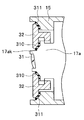
- FIG. 13 is a partial cross-sectional view schematically showing an enlarged peripheral configuration of the fixing screw for the coupler portion of FIG.
- the heat of the observation window 31 fixed in the tip 17ak causes the fixing screw 32 to be fixed. It is easy to be transmitted to the coupler unit 15 via.
- a heat insulating rubber sheet 310 is provided between the outer periphery of the main cover 17 a on the tip 17 ak side and the inner periphery of the fixing screw 32, and the outer periphery of the fixing screw 32.
- a structure for ensuring water tightness by providing a rubber sheet 311 for heat insulation between the inner periphery of the coupler portion 15 may be used.
- the contact area between the tip 17ak and the fixing screw 32 is reduced by the rubber sheet 310, and heat transfer to the coupler unit 15 side is reduced due to the heat insulating effect by the rubber sheet 310.
- the observation window 31 can be hardly fogged.
- the substrate folder 200 needs to be comprised from the resin material which has heat resistance to the high temperature / high pressure steam in an autoclave process
- the resin material which has heat resistance is limited, for example, Teflon (trademark) And Radel (registered trademark).
- Teflon (registered trademark) has heat resistance and bendability but has poor moldability
- Radel (registered trademark) has heat resistance but is hard, so it is difficult to bend and form in an L shape. was there.
- the substrate folder 200 may be formed of two parts, and the end of each part may be hinge-fixed to form an L shape via the hinge.
- the exterior member 17 is shown to be composed of titanium.
- the titanium surface is usually covered with a stable oxide film, it is difficult to discolor, but the oxide film becomes unstable when chemical polishing or blasting is applied to the outer surface in order to improve the appearance. Later, there was a problem that it easily changed color.
- the outer surface of the titanium exterior member 17 is blasted with a medium having a small shape ( ⁇ 45 to 53 ⁇ m) using a material that promotes oxidation (alumina or the like), and the outer surface is blasted.
- a stable and stable oxide film may be formed.
- the outer surface of the exterior member 17 has a large shape ( ⁇ 125 to 250 ⁇ m) using zirconia (glass acceptable) in order to improve the appearance quality by suppressing the gloss. You may blast with.
- a stable oxide film can be created on the outer surface of the titanium exterior member 17 and the appearance quality can be improved, so that discoloration of the appearance can be prevented even after the autoclave treatment. it can.
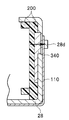
- FIG. 14 is a diagram schematically showing a cross section of the internal unit along line XIV-XIV in FIG. 5.
- the heat radiating plate 110 of the internal unit 150 is fixed to the frame 28 using a plurality of screws, but a structure that reduces the screw fixing portion has been desired.
- a protruding part 28 d is formed in which a part of the frame 28 protrudes outward, and a part of the heat radiating plate 110 is slid and locked in the protruding part 28 d. Accordingly, the screw fixing portion of the heat radiating plate 110 may be reduced by one place.
- the substrate held in the substrate folder 200 generates heat
- the heat is reliably transmitted to the heat radiating plate 110 via the heat radiating sheet 340 in contact with the substrate folder 200, so that the substrate is held in the substrate folder 200. It is also possible to improve the heat dissipation of the substrate.
- the flexible substrate 38 is bent into a U shape, and the connector 38 b at the end is electrically connected to the substrate 320. As a result, the flexible substrate 38 is compactly arranged in the rear cover 17b.
- a polyimide reinforcing sheet 38h may be provided at a portion facing the conductive pin 42 of the flexible substrate 38.
Abstract
内部を気密に保持するとともに金属から1層に構成された外装部材と、外装部材の内部に設けられた、撮像ユニットを有する内部ユニットと、内部ユニットに設けられた、該内部ユニットを保持するとともに内部ユニットを外装部材の内面17nに固定する少なくとも1つの固定部位120r、120lを有する、金属から構成された固定枠と、少なくとも1つの固定部位120r、120lと内面17nのネジ穴16r、16lとの間に設けられた、金属よりも熱伝導率の低い部材から構成されたワッシャ65r、65lと、を具備する。
Description
本発明は、内部を気密に保持するとともに金属から1層に構成された外装部材を具備する内視鏡用撮像装置に関する。
内視鏡用撮像装置は、被検体内における被検部位の像を撮像し、該撮像した被検部位の像をモニタに出力するものであり、例えば内視鏡の挿入部の基端側に設けられた接眼部(以下、アイピースと称す)に接続自在な構成が周知である。
また、内視鏡用撮像装置は、使用後、確実に洗浄、消毒及び滅菌する必要がある。内視鏡用撮像装置の滅菌方法としては、高温高圧蒸気を用いて滅菌する高温高圧蒸気滅菌処理(以下、オートクレーブ処理と称す)が周知である。
ここで、通常、内視鏡用撮像装置における撮像素子、対物光学系等からなる撮像ユニットを具備する内部ユニットは、内視鏡用撮像装置の外装部材内に設けられているが、オートクレーブ処理において、外装部材内にも高温高圧蒸気が進入する。
この際、撮像ユニットは、高温高圧蒸気に触れると、撮像素子が故障してしまったり、対物光学系が曇ったりしてしまうことから、撮像ユニットは、外装部材内において高温高圧蒸気が進入しない場所に設けられる必要がある。
そこで、日本国特開2013-56003号公報には、内視鏡の接眼部に装着される内視鏡用撮像装置において、ステンレス等の金属から構成された外装部材内に樹脂から構成された気密ケースを設け、該気密ケース内に撮像ユニットを具備する内部ユニットを封止する。このことにより、外装部材内に進入した高温高圧蒸気から撮像ユニットを保護する内視鏡用撮像装置の構成が開示されている。
しかしながら、日本国特開2013-56003号公報に開示された内視鏡用撮像装置の構成では、外装部材がステンレス等の重たい金属から構成されているとともに、外装部材内に気密ケースを有する2層のケース構造を有している。このため、内視鏡用撮像装置の重量が重くなってしまうといった問題があった。
このような問題に鑑み、外装部材が、ステンレスよりも重量の軽い、例えばチタンから構成され、さらに、外装部材自体が気密構造を有することにより外装部材が気密ケースを兼ねた1層のケース構造とする。このことによって、外装部材内に高温高圧蒸気が進入することなくかつ内視鏡用撮像装置の軽量化を図る構成も考えられる。
尚、1層の外装部材を金属から構成する必要があるのは、樹脂では気密構造を実現することが難しいばかりか、外装部材に内部ユニットの一部を半田固定する必要がある他、外装部材の端部に蓋をして外装部材内を気密封止する際、レーザ溶接を用いる必要がある等の理由からである。
ところで、外装部材を1層から構成した場合、内部ユニットは、該内部ユニットを保持する金属から構成された保持部材の少なくとも1つの固定部位が、内部ユニットの内面に設けられたネジ穴等の固定部に対して、ネジ等の固定部材によって固定される構成が考えられる。
尚、内部ユニットを外装部材の内面に直接固定するのは、内部ユニットが具備する対物光学系の光学特性を向上させるため、外装部材内において内部ユニットを位置精度良く固定する必要があるためである。
また、保持部材が金属から構成されているのは、内部ユニットの撮像素子は、駆動に伴い発熱する発熱体である。このことから、撮像素子の駆動に伴い、気密構造を有する外装部材内の温度が撮像素子の熱により上昇してしまう。この温度上昇に伴って撮像素子が故障してしまうことを防ぐため、保持部材を介して撮像素子の熱を外装部材に伝熱し、該外装部材外に放熱する必要があるためである。
しかしながら、この放熱構造では、外装部材に対して内部ユニットが保持部材の固定部位のみにて接触している場合、外装部材の固定部が局所的に熱されてしまうといった問題があった。
本発明は、上記問題点に鑑みなされたものであり、気密ケースを兼ねた1層の外装部材の内部ユニットの固定部が、該外装部材内の発熱体の熱により局所的に熱されてしまうことを防ぐことができる構成を具備する内視鏡用撮像装置を提供することを目的とする。
本発明の一態様における内視鏡用撮像装置は、内部を気密に保持するとともに金属から1層に構成された外装部材と、前記外装部材の前記内部に設けられた、発熱体を有する内部ユニットと、前記内部ユニットに設けられた、該内部ユニットを保持するとともに前記内部ユニットを前記外装部材の前記内面に固定する少なくとも1つの固定部位を有する、金属から構成された保持部材と、前記保持部材における少なくとも1つの前記固定部位と前記外装部材の前記内面の固定部との間に設けられた、金属よりも熱伝導率の低い部材から構成された断熱部材と、を具備する。
以下、図面を参照して本発明の実施の形態を説明する。尚、図面は模式的なものであり、各部材の厚みと幅との関係、それぞれの部材の厚みの比率などは現実のものとは異なることに留意すべきであり、図面の相互間においても互いの寸法の関係や比率が異なる部分が含まれていることは勿論である。
図1は、本実施の形態の内視鏡用撮像装置を備えた内視鏡システムの構成の概略を示す図である。
図1に示すように、内視鏡システム1は、内視鏡2と、該内視鏡2に接続自在な内視鏡用撮像装置であるカメラヘッド3と、内視鏡2に照明光を供給する光源装置4とを具備している。
図1は、本実施の形態の内視鏡用撮像装置を備えた内視鏡システムの構成の概略を示す図である。
図1に示すように、内視鏡システム1は、内視鏡2と、該内視鏡2に接続自在な内視鏡用撮像装置であるカメラヘッド3と、内視鏡2に照明光を供給する光源装置4とを具備している。
また、内視鏡システム1は、カメラヘッド3からの撮像信号に対して信号処理等を行うカメラコントロールユニット(CCU)5と、該CCU5から出力される映像信号を表示するモニタ6とを具備している。
内視鏡2は、細長な挿入部7と、該挿入部7の基端側に設けられた挿入部7よりも太径の把持部8と、該把持部8の基端に設けられたアイピース9とを有して主要部が構成されている。
また、内視鏡2の把持部8の側部に設けられている口金に、一端が光源装置4にコネクタ11を介して着脱自在なライトガイドケーブル10の他端が接続自在となっている。
このことにより、光源装置4内の図示しないランプから発光された光は、ライトガイドケーブル10を介して、内視鏡2に供給され、挿入部7の先端に設けられた図示しない照明窓から被検体内に照射される。
照明光によって照明された被検体内の像は、挿入部7の先端に設けられた図示しない対物光学系に光学像が結像され、該結像された光学像は、挿入部7内に設けられた図示しないリレーレンズ等を介して、アイピース9内に設けられたレンズに入射される。このことから、作業者がアイピース9を介して光学像を観察することができるようになっている。
また、上述したように、内視鏡2のアイピース9に、カメラヘッド3が接続自在である。カメラヘッド3からはカメラケーブル12が延出されており、該カメラケーブル12の延出端は、該延出端に設けられたコネクタ13を介してCCU5に着脱自在となっている。
CCU5は、カメラヘッド3からカメラケーブル12を介して送信された撮像信号に基づいて画像信号を生成し、被検体内の像を、内視鏡画像としてモニタ6に表示させるものである。
次に、図2~図5を用いて上述したカメラヘッド3の具体的な構成を説明する。図2は、図1のカメラヘッドを示す斜視図、図3は、図2中のIII-III線に沿うカメラヘッドの部分断面図、図4は、図3の内部ユニットを示す斜視図、図5は、図3の内部ユニットを図4とは異なる方向からみた斜視図である。
図2、図3に示すように、カメラヘッド3は、カプラ部15と、該カプラ部15に先端が固定された外装部材17とを有して主要部が構成されている。
図3に示すように、カプラ部15は、内視鏡2のアイピース9が接続される部材であり、外装部材17の先端17ak側の外周に対して、固定ネジ32が用いられて固定されている。
外装部材17は、内部を気密に保持するとともに金属から1層に構成されており、メインカバー17aと、該メインカバー17aの基端に、半田、溶接等により水密気密に固定されたリヤカバー17bとから構成されている。即ち、外装部材17は、気密ケースを兼ねている。
尚、外装部材17を構成する金属としては、軽量化を図るため、例えばチタンが挙げられる。
また、外装部材17を構成する金属としては、軽量かつ熱伝導率の低いものが望ましい。しかしながら、上述したオートクレーブ処理における高温高圧蒸気の内部17iへの進入を防ぐために行う気密溶接ができる金属であれば、ステンレス等どのようなものであっても構わない。
また、図2、図3に示すように、メインカバー17aの一側面、具体的には、図2、図3に示す図中上部の外周側面に、被検体内の像の撮像操作に用いられるスイッチユニット170がカメラヘッド3の長手方向Nに沿って固定されている。
スイッチユニット170は、ゴムカバー等によって覆われた複数のスイッチボタン19と、該複数のスイッチボタン19を水密的にメインカバー17aに取り付けるスイッチボタン枠18とを具備している。
複数のスイッチボタン19は、後述するレンズ30(図3参照)の一部を前後に移動させて焦点調整を行う焦点調整ボタン19aや、レンズ30の一部を前後に移動させて焦点倍率を調整するズームボタン19bや、明るさ調整ボタン19cや、色調整ボタン19dや、レリーズボタン19e等を有している。
また、スイッチボタン枠18は、金属よりも熱伝導性の低い部材、例えば樹脂材料から構成されており、メインカバー17aの上部を長手方向Nに沿って覆っている。
また、図3に示すように、外装部材17によって気密に封止された内部17iに、発熱体である撮像ユニット100を有する図3~図5に示す内部ユニット150が設けられている。
尚、内部ユニット150は、組み付けの際、外装部材17におけるメインカバー17aにリヤカバー17bが固定されていない状態において、メインカバー17aの後方の開口から内部17iに挿入される。
これは、本構成においては、メインカバー17aは、1部品から構成されている。このため、複数部品から構成されている場合に比べ、後述する外装部材17の固定部に、内部ユニット150の固定枠120の各固定部位120u、120r、120lを付き当てて固定する構成においては、内部ユニット150の位置精度が向上することから、レンズ30の光学的な偏芯等を防ぐことができるためである。
撮像ユニット100は、複数のレンズ30と、該レンズ30を保持するレンズ枠51と、撮像素子33と、各種基板等の電気部品を具備して主要部が構成されている。
より具体的には、図3に示すように、複数のレンズ30は、メインカバー17aの先端17ak内に、外周がメタライズ化されることにより半田等によって気密に固定された観察窓31に対して長手方向Nに対向して位置している。
尚、観察窓31は、カメラヘッド3のカプラ部15に、内視鏡2のアイピース9が接続された際、アイピース9内のレンズに対して、長手方向Nにおいて対向して位置する。
また、外装部材17の内部17iにおいて、観察窓31の後方に、レンズ枠51によって保持された複数のレンズ30が設けられており、該複数のレンズ30の結像位置に、撮像素子33が位置している。
尚、レンズ枠51及び撮像素子33は、長手方向Nにおいてレンズ枠51と撮像素子33との間に設けられた保持部材である固定枠120に保持されている。
固定枠120は、内部ユニット150を保持するものであり、撮像素子33の熱を逃がすため金属から構成されている。
また、固定枠120は、図3~図5に示すように、内部ユニット150をメインカバー17aの内面17nに固定する固定部位120u、120r、120lを有している。
尚、図4、図5に示すように、固定部位120uは、図中上部に設けられており、固定部位120rは、観察窓31を前方とした場合、図中下側かつ右側に設けられており、固定部位120lは、観察窓31を前方とした場合、図中下側かつ左側に設けられている。
具体的には、固定部位120u、120r、120lは、内部ユニット150の周方向において、略120°毎に設けられている。
尚、固定枠120の固定部位は、3つ以外の複数であっても、1つであっても構わない。また、固定枠120の固定部位120u、120r、120lを用いた内面17nへの固定構成は、後述する。
また、以下、固定部位120uを上部側固定部位120u、固定部位120r、120lを、下部側固定部位120r、120lと称す。
また、図3に示すように、内部ユニット150は、外装部材17の内部17iにおいて、内面17nに、固定枠120の固定部位120u、120r、120lと、後述する放熱シート140以外は非接触となるよう設けられている。
さらに、図3に示すように、外装部材17の内部17iにおいて、撮像素子33の後方に、L字状に折り曲げられた基板フォルダ200に保持されるとともに撮像素子33に電気的に接続された各種基板が設けられている。
各種基板は、基板フォルダ200の後方に位置する基板35に、U字状に折り曲げられたフレキシブル基板138を介して電気的に接続されている。
基板フォルダ200及び基板35は、固定枠120の外周に固定されたフレーム28に固定されている。
基板35に、フレキシブル基板138とは上下逆さのU字状に折り曲げられて基板35から延出されたフレキシブル基板38のコネクタ38aが電気的に接続されている。
また、フレキシブル基板38の延出端に設けられたコネクタ38bは、基板35よりも後方において傾いて設けられた基板320に電気的に接続されている。
基板320の基端側には、リヤカバー17bの端部の内面17nに対して溶接等によって固定されたハーメチックコネクタ160が設けられており、該ハーメチックコネクタ160の基端側には、基板45が設けられている。
ハーメチックコネクタ160には、該ハーメチックコネクタ160を貫通する導通ピン42が複数設けられており、導通ピン42により基板320と基板45とは電気的に接続されている。
また、図3に示すように、リヤカバー17bの基端側に、金属から構成された口金であるケーブル固定枠41の先端が、ハーメチックコネクタ160を介して接続されている。
尚、リヤカバー17bの基端側の外周、ハーメチックコネクタ160の外周及びケーブル固定枠41の先端側の外周には、金属から構成された外装部材外伝熱部材であるヒートシンク130が被覆されている。尚、ヒートシンク130は、チタンから構成されたリヤカバー17bよりも熱伝導率の良い材料、例えば銅材から構成されている。
さらに、ケーブル固定枠41の基端に、スペーサリング179が固定されており、スペーサリング179の内周面には、カメラケーブル12の先端が接続されている。
カメラケーブル12の内部には、金属の導体の外周に該金属よりも熱伝導率の低い部材、例えば樹脂材料から構成された複数の電気コードが収納されており、該電気コードの先端は、ケーブル固定枠41内まで延出され、基板45に電気的に接続されている。
また、カメラケーブル12の外周面には、カメラケーブル12の急激な屈曲を防止する折れ止め44が被覆されている。
また、折れ止め44の外周には、リヤネジ50が移動自在に被覆されており、リヤネジ50により、カメラケーブル12の先端側が、ケーブル固定枠41に水密気密に固定される。
さらに、リヤカバー17bの先端から、リヤネジ50の先端まで、リヤカバー17bの外周、ヒートシンク130の外周及びケーブル固定枠41の基端側の外周を覆うように、金属よりも熱伝導率の低い部材、レーデル(登録商標)やPEEK等の樹脂材料から構成された外装カバー40が設けられている。
ここで、固定枠120に、該固定枠120から、外装部材17の内部17iにおいて、外装カバー40によって覆われた領域R1まで延出された外装部材内伝熱部材である放熱板110が固定されている。尚、放熱板110は、金属から構成されている。
即ち、放熱板110は、固定枠120から、リヤカバー17bの内部まで、図3~図5に示すように、フレーム28の外周面に沿って図中上向きコの字状を有して後方に延出されている。
尚、放熱板110は、金属から構成された固定枠120に接続されていることにより、撮像素子33から固定枠120に伝熱された熱がさらに伝熱され、内部ユニット150の後方まで伝達する。
また、図3~図5に示すように、放熱板110の基端面に、熱伝導率の比較的高いゴム状(ゲル状)のシートから構成された放熱シート140が、リヤカバー17bの内面17nに押し潰された状態にて、内面17nに面接触して設けられている。このことにより、放熱シート140の熱は、リヤカバー17bに確実に伝達される。
よって、撮像素子33から固定枠120に伝熱された熱は、放熱板110、放熱シート140、リヤカバー17bを介してヒートシンク130まで伝達され、その後、ケーブル固定枠41を介してカメラケーブル12の導体に伝達される。
即ち、外装カバー40によって覆われた領域R1まで伝達された後、カメラケーブル12に伝達される。尚、上述したように、ヒートシンク130は、リヤカバー17bよりも熱伝導率の高い金属から構成されていることから、リヤカバー17bの熱は、外部に逃げず効率良くヒートシンク130に伝達される。
外装カバー40は、リヤカバー17bの外周、ヒートシンク130の外周及びケーブル固定枠41の基端側の外周を覆うことにより、それぞれ金属から構成されたリヤカバー17b、ヒートシンク130、ケーブル固定枠41から熱が外部に直接放熱されてしまうことを防いでいる。言い換えれば、外装カバー40は、操作者が、リヤカバー17b、ヒートシンク130、ケーブル固定枠41に直接接触してしまうことを防いでいる。
次に、外装部材17のメインカバー17aの内面17nに対する内部ユニット150の固定構成を、図3~図5及び図6、図7を用いて説明する。図6は、図3の固定枠の上部側固定部位を拡大して示す部分断面図、図7は、図4、図5の固定枠の下部側固定部位を拡大して示す部分断面図である。
上述したように、内部ユニット150は、固定枠120の上部側固定部位120u及び下部側固定部位120r、120lが、外装部材17のメインカバー17aの内面17nに固定されることによって外装部材17の内部17iに設けられる。
具体的には、図3~図6に示すように、外装部材17のメインカバー17aの内面17nにおいて、上部側固定部位120uに対向する位置に、固定部であるネジ穴16uが形成されている。
また、図4、図5、図7に示すように、メインカバー17aの内面17nにおいて、下部側固定部位120r、120lに対向する位置に、固定部であるネジ穴16r、16lが形成されている。
図6に示すように、上部側固定部位120uに、長手方向Nに貫通する貫通孔120uhが形成されている。
貫通孔120uhに挿通された固定部材であるネジ60uが、該ネジ60uの外周に被覆された金属ワッシャ61uを介してネジ穴16uに螺合されることにより、上部側固定部位120uは内面17nに、金属を介して固定される。
尚、金属ワッシャ61uは、上部側固定部位120uと内面17nとの間に位置している。
その結果、固定枠120は、図3に示すように、スイッチユニット170の樹脂材料から構成されたスイッチボタン枠18によって覆われた外装部材17のメインカバー17aの領域R2に接続される。
よって、撮像素子33から固定枠120に伝熱された熱は、上部側固定部位120u、ネジ60u、金属ワッシャ61uを介して外装部材17のメインカバー17aにおけるスイッチボタン枠18によって覆われた領域R2に伝達される。
スイッチボタン枠18は、メインカバー17aの上部側の外周を覆うことにより、メインカバー17aの上部側から熱が外部に直接放熱されてしまうことを防いでいる。言い換えれば、スイッチボタン枠18は、操作者が、メインカバー17aの上部側に直接接触してしまうことを防いでいる。
また、図7に示すように、下部側固定部位120r、120lに、長手方向Nに貫通する貫通孔120rh、120lhが形成されている。
貫通孔120rh、120lhに挿通された固定部材であるネジ60r、60lが、該ネジ60r、60lの外周に被覆された断熱部材であるワッシャ65r、65l、ブッシュ66r、66lを介してネジ穴16r、16lに螺合されることにより、下部側固定部位120r、120lは内面17nに、ワッシャ65r、65l、ブッシュ66r、66lを介して固定される。
尚、ワッシャ65r、65l、ブッシュ66r、66lは、金属よりも熱伝導率の低い部材から構成されている。
また、ワッシャ65r、65lは、下部側固定部位120r、120lと内面17nとの間に位置している。
即ち、金属から構成されている下部側固定部位120r、120lは、金属から構成されているメインカバー17aの内面17nに直接接触しない構造となっている。
ワッシャ65r、65l、ブッシュ66r、66lは、金属よりも熱伝導率の低い部材から構成されていることにより、撮像素子33から固定枠120に伝熱された熱が、下部側固定部位120r、120lを介して外装部材17のメインカバー17aに伝達されてしまい、メインカバー17aのネジ穴16r、16l付近が局所的に熱されてしまうことを防ぐ部材である。
尚、ワッシャ65r、65lの内周面にネジ溝が形成されていれば、ワッシャ65r、65lを、ネジ60r、60lの外周に被覆させた際、ワッシャ65r、65lは、ネジ60r、60lの外周に螺合されるため、ワッシャ65r、65lの脱落を防止することができる。
尚、その他のカメラヘッド3の構成は周知であるため、その説明は省略する。
このように、本実施の形態においては、内部ユニット150を外装部材17の内面17nのネジ穴16u、16r、16lにそれぞれネジ60u、60r、60lを用いて固定する構造において、固定枠120の下部側固定部位120r、120lは、ネジ60r、60lが、ワッシャ65r、65l、ブッシュ66r、66lを介してネジ穴16r、16lに螺合されることにより、内面17nに、ワッシャ65r、65l、ブッシュ66r、66lを介して固定されると示した。
即ち、下部側固定部位120r、120lは、メインカバー17aに直接接触しないと示した。
また、内部ユニット150は、上部側固定部位120u、下部側固定部位120r、120l、放熱シート140を除いて、外装部材17の内面17nに非接触に固定されると示した。
このことによれば、撮像素子33から固定枠120に伝熱された熱が、下部側固定部位120r、120lから、メインカバー17aのネジ穴16r、16lが形成された部位に伝達されてしまうことを、樹脂材料から構成された断熱部材であるワッシャ65r、65l、ブッシュ66r、66lによって防ぐことができる。
即ち、メインカバー17aにおいて、操作者が触れる可能性があるネジ穴16r、16l付近が局所的に熱されてしまうことを防ぐことができる。
さらに、本実施の形態においては、撮像素子33から固定枠120に伝熱された熱は、固定枠120に接続されるとともに樹脂材料によって覆われた領域R1、R2に設けられた金属に伝達されると示した。
具体的には、固定枠120に、領域R1まで延出する放熱板110が接続されており、撮像素子33から固定枠120に伝熱された熱は、放熱板110、放熱シート140、リヤカバー17bを介してヒートシンク130まで伝達され、その後、ケーブル固定枠41を介してカメラケーブル12の導体に伝達されると示した。即ち、外装カバー40によって覆われた領域R1まで伝達された後、ケーブル12に伝達されると示した。
さらに、固定枠120の上部側固定部位120uに、外装部材17のメインカバー17aにおけるスイッチボタン枠18によって覆われた領域R2が接続されており、撮像素子33から固定枠120に伝熱された熱は、上部側固定部位120u、ネジ60u、金属ワッシャ61uを介して外装部材17のメインカバー17aにおけるスイッチボタン枠18によって覆われた領域R2に伝達されると示した。
このことによれば、撮像素子33の熱、即ち、外装部材17の内部17iの熱は、領域R1、R2に位置する操作者によって非接触となる金属に逃がされて放熱されることから、操作者が直接接触するカメラヘッド3における金属部位には熱伝達され難い。
このため、外装部材17の内部17iの温度を低減することができるとともに、外装部材17を金属から構成したとしても、操作者が接触する外装部材17の部位やカメラヘッドの他の部位の温度を低減することができる。
以上から気密ケースを兼ねた1層の外装部材17の内部ユニット150の固定部が、該外装部材17の内部17iの撮像ユニット100の熱により局所的に熱されてしまうことを防ぐことができる構成を具備するカメラヘッド3を提供することができる。
尚、以下、変形例を、図8を用いて示す。図8は、図6の固定枠における上部側固定部位の形状の変形例を示す部分断面図である。
ところで、外装部材17の内面17nに内部ユニット150を固定する際、内部ユニット150の構成部品の破損を防ぐとともに、レンズ30の光学精度を向上させるため、出来るだけ位置精度良く内部ユニット150が固定できる構造が望まれている。
具体的には、外装部材17の内面17nに対して、内部ユニット150は、該内部ユニット150の重心位置で固定することが好ましい。
これは、カメラヘッド3に衝撃や、振動等の負荷が加わった際における外装部材17における内部ユニット150の固定部が破損、変形等した際のレンズ30の光学偏芯等を考慮すると、内部ユニット150の重心位置で固定することが好ましいためである。
しかしながら、上述したように、外装部材17を1層から構成するととともに内部ユニット150を重心位置で固定しようとすると、外装部材17における内部ユニット150の固定部、即ち、内部ユニット150を固定するためのネジ60u、60r、60lが螺合されるネジ穴16u、16r、16lの長手方向Nの位置が、メインカバー17aの基端から前方に離れてしまう。
その結果、ドライバ等の工具を用いたネジ60u、60r、60lの螺合作業、即ちカメラヘッド3の組立作業が行い難くなるといった問題があった。
具体的には、例えば、内部ユニット150を、メインカバー17aの基端の開口から内部に進入させ、各固定部位120u、120r、120lを、メインカバー17aの固定部に当接させた後、各固定部位120u、120r、120lに形成された貫通孔120uh、120rh、120lhを介してネジ穴16u、16r、16lにドライバ等の工具を用いてネジ60u、60r、60lを螺合させる作業が難しくネジ60u、60r、60lを落下させてしまう可能性がある。
また、ネジ60u、60r、60lの貫通孔120uh、120rh、120lhからの長手方向Nにおける落下を防ぐため、事前にネジ60u、60r、60lを貫通孔120uh、120rh、120lhに挿通しておき、上述したようにネジ60u、60r、60lの外周に落下防止用のワッシャ61u、61r、61lを被覆させておく構成も考えられる。
しかしながら、この構成では、図5、図6に示すように、外装部材17の内面17nにおける固定部にワッシャ61u、61r、61lが突き当たってしまうため、内部ユニット150の付き当て位置精度が落ちてしまい、固定後、内部ユニット150のレンズ30が偏芯してしまう可能性がある。
そこで、図8に示すように、上部側固定部位120uの長手方向Nの略中央位置に摺割り120usが設けられ、該摺割り120usに、金属ワッシャ61uが設けられる構成が考えられる。
このような構成によれば、金属ワッシャ61uにより、従来と同様、ネジ60uの脱落を防ぐことができる他、外装部材17の内面17nにおける固定部には、上部側固定部位120uが直接接触する。このため、内部ユニット150を位置精度良く固定することができるととともに、カメラヘッド3の組立性が向上する。
尚、以上の構成は、下部側固定部位120r、120lにおいては適用できない。これは、上述したように、金属から構成された下部側固定部位120r、120lが、外装部材17に直接接触してしまうと熱が伝熱されてしまい、外装部材17の固定部が局所的に熱されてしまうためである。
また、その他にも、ネジ60uの頭が、メインカバー17aの基端付近まで位置する長さを有するネジ60uを用いれば、ネジ穴16uに対してドライバ等の工具を用いたネジ60uを螺合させる作業がより容易になる他、ネジ60uに伝達された熱のネジ60uからの拡散性を向上させることもできる。
また、ネジ60uを熱伝導率の高い材料から構成し、該ネジ60uを筒状の放熱素材で覆う構成や、ネジ60uの頭をローレット状にしてネジ60uの頭の表面積を増やす構成にすれば、よりネジ60uに伝達された熱のネジ60uからの拡散性を向上させることができる。
尚、上述した本実施の形態においては、外装部材17は、チタン等の金属から構成されていると示した。
これは、チタンは、他の金属に比べて高強度かつ軽いため、外装部材として用いるとカメラヘッド3を小型化及び軽量化し易くなるためである。
しかしながら、外装部材17のメインカバー17aの内部17iに設けられた撮像ユニット100が発熱し、メインカバー17aに熱伝達されてしまうと、撮像ユニット100近傍のメインカバー17aの部位が局所的に熱されてしまう可能性がある。
そこで、メインカバー17aの内面17nに、熱伝導率の高い金属、例えば金のメッキが施されていても良い。
このことによれば、メインカバー17aの外表面に熱が伝わる前に、内面17nにおいて熱が拡散することから、メインカバー17aの外表面の局所的な温度上昇を防ぐことができる。
尚、リヤカバー17bの内面17nにも金メッキが施されていても良い。このことによれば、メインカバー17aの内面17nの熱を、リヤカバー17bの内面17nまで効率良く拡散することができる。即ち、外装部材17全体から熱を逃がすことができるため、外装部材17の一部が局所的に熱されてしまうことを効果的に防ぐことができる。
尚、以下、変形例を、図9~図12を用いて示す。図9は、図3の内部ユニットの外装部材の変形例の構成を、外装カバー及びカメラケーブルとともに概略的に示す図、図10は、図9の外装カバーを拡大して示す部分断面図、図11は、図9中のXI線で囲った部位を拡大して示す部分断面図、図12は、図11の水密シールが設けられる位置の変形例を示す部分断面図である。
上述したように、外装部材17を1層から構成して、内部17iに内部ユニット150を気密封止した後、内部ユニット150の不具合等により、外装部材17を開封して気密を解除する必要が生じる。この場合、例えばメインカバー17aの基端外周全体に、リヤカバー17bの先端外周全体を溶接する構成を用いていると、全周の溶接部を削って開封しなければならない。
このため、切削加工が大変である他、メインカバー17aの基端外周の肉厚を余分に増やして削りシロを設けておかないと、高価なチタンから構成された外装部材17の再利用が出来なくなってしまうといった問題があった。
尚、以上の問題は、メインカバー17aの先端外周に図示しない先端カバーを溶接して気密に固定する構成においても同様である。
このような問題に対応するため、図9~図11に示すように、外装部材17を、前方突出部17t1、後方突出部17t2を有するメインカバー17g、前方突出部17t1を有する先端カバー17f、後方突出部17t2を有するリヤカバー17hの3つから構成しても良い。
このような構成においては、メインカバー17gの先端に対して先端カバー17fが、各前方突出部17t1において全周に溶接固定され、メインカバー17gの基端に対してリヤカバー17hが、各後方突出部17t2において全周に溶接部302において固定される。
尚、各突出部17t1、17t2の長手方向Nのおける長さは、レーザ溶接における溶接部302の溶接深さの2倍以上に設定されている。
よって、外装部材17を開封する際は、外装部材17のリヤ側であれば、図11の点線に示すように、後方突出部17t2を削り込めば良い。
その結果、後方突出部17t2が削れるだけのため、再度、後方突出部17t2を溶接すれば、簡単に外装部材17を後方突出部17t2が無くなるまで、複数回再利用することができる。
さらに、削られる後方突出部17t2は、外装部材17の内部17iから離間した位置に設けられているため、削り屑が内部17iに進入してしまうことを防ぐことができる。
尚、このことは、外装部材17のフロント側、即ち前方突出部17t1においても同様である。
また、リヤカバー17h側のみ図示するが、図11に示すように、後方突出部17t2は、外装カバー40により外周が水密的に覆われていることから、外部に露出されない。
さらに、図11に示すように、外装カバー40の先端は、メインカバー17gの基端面に突き当たっており、外装カバー40の先端側の内周面は、水密シール303を介して後方突出部17t2の外周面に当接していることにより、水密性が保持されている。
尚、図12に示すように、水密シール303は、外装カバー40の先端とメインカバー17gの基端面との間に設けられていても構わない。
よって、外装部材17の開封のため、後方突出部17t2を削ったとしても、カメラヘッド3の外観が変化することが無く、また水密性にも影響がない。
尚、以下、変形例を、図13を用いて示す。図13は、図3のカプラ部用の固定ネジの周辺構成を拡大して概略的に示す部分断面図である。
上述したように、カプラ部15が、固定ネジ32が用いられてメインカバー17aの先端17ak側に固定される構成においては、先端17ak内に固定されている観察窓31の熱が固定ネジ32を介したカプラ部15に伝達されやすい。
その結果、カプラ部15に内視鏡2のアイピース9を接続すると、カプラ部15の熱により、観察窓31が曇りやすくなってしまうといった問題があった。
また、固定ネジ32の前後に水密用のOリングを用いると、固定ネジ32とメインカバー17aの先端17ak側との接触面積が増えてしまい、外観形状が複雑になってしまうといった問題もあった。
このような問題に鑑み、図13に示すように、メインカバー17aの先端17ak側の外周と固定ネジ32の内周との間に、断熱用のゴムシート310が設けられ、固定ネジ32の外周とカプラ部15の内周との間に、断熱用のゴムシート311が設けられていることにより水密性を確保する構成を用いても良い。
このような構成によれば、ゴムシート310により、先端17akと固定ネジ32との接触面積が減るとともに、ゴムシート310による断熱効果のため、カプラ部15側への熱伝達が減少する。
よって、カプラ部15にアイピース9を接続した際に、観察窓31を曇り難くすることができる。
さらに、ゴムシート310、311を挟むだけの簡単な構成のため、外観も簡素化されることから、洗浄消毒性も向上する。
尚、固定ネジ32を、チタンや樹脂等の熱伝導率の低い材料から構成しても良い。このことによれば、固定ネジ32を介した伝熱性が低下することから、より一層、観察窓31が曇り難くなる。
上述した図3に示すように、外装部材17の内部17iにおいて、撮像素子33の後方に、L字状に折り曲げられた基板フォルダ200に保持されるとともに撮像素子33に電気的に接続された各種基板が設けられていると示した。
ここで、基板フォルダ200は、オートクレーブ処理における高温高圧蒸気に耐熱性の有る樹脂材料から構成されている必要があるが、耐熱性を有する樹脂材料は限られており、例えば、テフロン(登録商標)、レーデル(登録商標)が挙げられる。
しかしながら、テフロン(登録商標)は、耐熱性や折り曲げ性はあるものの成形性が悪く、レーデル(登録商標)は、耐熱性はあるものの硬いため、L字状に折り曲げて成形することが難しいといった問題があった。
このような問題に鑑み、基板フォルダ200を、2部品から構成し、各部品の端部をヒンジ固定することにより、ヒンジを介してL字状に形成しても良い。
このような構成によれば、曲げ性、成形性を考慮することなく、耐熱性を有する樹脂材料を基板フォルダ200に用いることが出来るため、低コスト化を図ることができる他、樹脂材料の選択範囲が広がる。
上述したように、本実施の形態においては、外装部材17は、チタンから構成されていると示した。
しかしながら、チタン表面は、通常は安定した酸化膜で覆われているため変色し難いが、外観を向上させるため、外表面に化学研磨やブラストを施すと酸化膜が不安定になるため、オートクレーブ処理後、変色しやすいといった問題があった。
このような問題に鑑み、チタン製の外装部材17の外表面に、酸化を促進する材質(アルミナ等)を用いて、小さい形状(φ45~53μm)のメディアでブラストを行い、外表面にブラストが残留して安定した酸化膜を形成しても良い。
但し、この状態では、外観は変化しないため、外装部材17の外表面に、光沢を抑えることにより外観品位を向上させるため、ジルコニア(ガラス可)等を用いて大きい形状(φ125~250μm)のメディアでブラストを行っても良い。
このことによれば、チタン製の外装部材17の外表面に、安定した酸化膜を作り出せるとともに、外観品位を向上させることができるため、オートクレーブ処理後であっても外観の変色を防止することができる。
尚、以下、変形例を、図14を用いて示す。図14は、図5中のXIV-XIV線に沿う内部ユニットの断面を概略的に示す図である。
通常、内部ユニット150の放熱板110は、フレーム28に対して複数のネジが用いられて固定されているが、ネジ固定部を減らす構造が望まれていた。
よって、図5、図14に示すように、フレーム28の一部が外側に突出された突出部28dが形成され、突出部28d内に、放熱板110の一部がスライドされて係止されることにより、放熱板110のネジ固定部を1箇所減らす構成にしても良い。
また、基板フォルダ200とフレーム28との間に弾力性を有する放熱シート340が設けられることにより、放熱板110の一部は、図14に示すように、放熱シート340の弾性力により、突出部28dに押し付けられて係止される。このことから、突出部28dから放熱板110の一部が抜けてしまうことが防がれる。
また、基板フォルダ200内に保持された基板は発熱するが、熱は、基板フォルダ200に接触する放熱シート340を介して確実に放熱板110に伝達されることから、基板フォルダ200内に保持された基板の熱の放熱性を向上させることもできる。
図3において上述したように、フレキシブル基板38は、U字状に折り曲げられて、端部のコネクタ38bが基板320に電気的に接続されている。このことにより、リヤカバー17b内においてフレキシブル基板38がコンパクトに配置されている。
しかしながら、この構成においては、フレキシブル基板38が導通ピン42に接触してしまうことを防ぐ絶縁シートを配置するスペースを確保することが難しい。
よって、図3に示すように、絶縁シートの代わりに、フレキシブル基板38の導通ピン42に対向する部位に、ポリイミドの補強シート38hが設けられていても構わない。
このような構成によれば、カメラヘッド3の小型化を実現しつつ、確実に補強シート38hにより、フレキシブル基板38と導通ピン42との絶縁性を確保することができる。
本出願は、2016年2月2日に日本国に出願された特願2016-018119号を優先権主張の基礎として出願するものであり、上記の内容は、本願明細書、請求の範囲、図面に引用されたものである。
Claims (11)
- 内部を気密に保持するとともに金属から1層に構成された外装部材と、
前記外装部材の前記内部に設けられた、発熱体を有する内部ユニットと、
前記内部ユニットに設けられた、該内部ユニットを保持するとともに前記内部ユニットを前記外装部材の内面に固定する少なくとも1つの固定部位を有する、金属から構成された保持部材と、
前記保持部材における少なくとも1つの前記固定部位と前記外装部材の前記内面の固定部との間に設けられた、金属よりも熱伝導率の低い部材から構成された断熱部材と、
を具備することを特徴とする内視鏡用撮像装置。 - 前記保持部材における少なくとも1つの前記固定部位は、前記外装部材の前記固定部に対して前記断熱部材を介して固定部材により固定されており、
前記断熱部材は、前記固定部材の外周に被覆されていることを特徴とする請求項1に記載の内視鏡用撮像装置。 - 前記保持部材は、該保持部材の一部が前記金属よりも熱伝導率の低い部材によって覆われた領域に設けられた金属に接続されていることを特徴とする請求項1または2に記載の内視鏡用撮像装置。
- 前記外装部材は、該外装部材の一部が前記金属よりも熱伝導率の低い部材によって覆われているとともに、前記保持部材の前記固定部位は、複数から構成されており、
複数の前記固定部位の内、前記外装部材における前記金属よりも熱伝導率の低い部材によって覆われた領域に対向する前記固定部位は、前記外装部材の前記固定部に接触して接続されていることを特徴とする請求項3に記載の内視鏡用撮像装置。 - 前記外装部材は、該外装部材の一部が前記金属よりも熱伝導率の低い部材を有する撮像操作に用いられるスイッチユニットによって覆われていることを特徴とする請求項4に記載の内視鏡用撮像装置。
- 前記外装部材は、端部側の外周が、前記金属よりも熱伝導率の低い部材によって覆われており、
前記保持部材に、前記外装部材の前記端部内まで延出される金属から構成された外装部材内伝熱部材が接続されていることを特徴とする請求項3に記載の内視鏡用撮像装置。 - 前記外装部材の前記端部に、外周が前記金属よりも熱伝導率の低い部材によって覆われた金属から構成された口金が、金属から構成された外装部材外伝熱部材を介して接続されていることを特徴とする請求項6に記載の内視鏡用撮像装置。
- 前記口金に、内部に金属の導体を有するとともに該導体の外周が前記金属よりも熱伝導率の低い部材によって覆われたケーブル部が接続されていることを特徴とする請求項7に記載の内視鏡用撮像装置。
- 前記発熱体は、撮像素子を有する撮像ユニットであることを特徴とする請求項1~8のいずれか1項に記載の内視鏡用撮像装置。
- 前記金属よりも熱伝導率の低い部材は、樹脂材料であることを特徴とする請求項1~9のいずれか1項に記載の内視鏡用撮像装置。
- 前記熱伝導率の低い部材によって覆われた領域に設けられた金属は、放熱シートとリヤカバーとを具備しており、
前記放熱シートは、前記外装部材内伝熱部材の基端面において、前記リヤカバーの内面に押し潰された状態において、前記内面に面接触して設けられていることを特徴とする請求項6に記載の内視鏡用撮像装置。
Priority Applications (4)
| Application Number | Priority Date | Filing Date | Title |
|---|---|---|---|
| EP16889367.5A EP3272272A4 (en) | 2016-02-02 | 2016-10-31 | IMAGING DEVICE WITH ENDOSCOPE |
| JP2017530779A JP6184655B1 (ja) | 2016-02-02 | 2016-10-31 | 内視鏡用撮像装置 |
| CN201680023811.0A CN107529973B (zh) | 2016-02-02 | 2016-10-31 | 内窥镜用摄像装置 |
| US15/788,355 US10813542B2 (en) | 2016-02-02 | 2017-10-19 | Image pickup apparatus for endoscope |
Applications Claiming Priority (2)
| Application Number | Priority Date | Filing Date | Title |
|---|---|---|---|
| JP2016018119 | 2016-02-02 | ||
| JP2016-018119 | 2016-02-02 |
Related Child Applications (1)
| Application Number | Title | Priority Date | Filing Date |
|---|---|---|---|
| US15/788,355 Continuation US10813542B2 (en) | 2016-02-02 | 2017-10-19 | Image pickup apparatus for endoscope |
Publications (1)
| Publication Number | Publication Date |
|---|---|
| WO2017134884A1 true WO2017134884A1 (ja) | 2017-08-10 |
Family
ID=59500190
Family Applications (1)
| Application Number | Title | Priority Date | Filing Date |
|---|---|---|---|
| PCT/JP2016/082325 WO2017134884A1 (ja) | 2016-02-02 | 2016-10-31 | 内視鏡用撮像装置 |
Country Status (5)
| Country | Link |
|---|---|
| US (1) | US10813542B2 (ja) |
| EP (1) | EP3272272A4 (ja) |
| JP (1) | JP6184655B1 (ja) |
| CN (1) | CN107529973B (ja) |
| WO (1) | WO2017134884A1 (ja) |
Cited By (2)
| Publication number | Priority date | Publication date | Assignee | Title |
|---|---|---|---|---|
| WO2018116533A1 (ja) * | 2016-12-19 | 2018-06-28 | オリンパス株式会社 | 医療用撮像装置 |
| WO2019225108A1 (ja) * | 2018-05-24 | 2019-11-28 | オリンパス株式会社 | 内視鏡用外付機構 |
Families Citing this family (6)
| Publication number | Priority date | Publication date | Assignee | Title |
|---|---|---|---|---|
| JP6411731B2 (ja) * | 2013-12-04 | 2018-10-24 | オリンパス株式会社 | 撮像装置及び内視鏡 |
| CN109124548A (zh) * | 2018-07-09 | 2019-01-04 | 卓外(上海)医疗电子科技有限公司 | 具备良好热处理的电子内窥镜 |
| JP7330802B2 (ja) * | 2019-08-02 | 2023-08-22 | ソニー・オリンパスメディカルソリューションズ株式会社 | カメラヘッド |
| CN112656354A (zh) * | 2019-10-16 | 2021-04-16 | 深圳迈瑞生物医疗电子股份有限公司 | 内窥镜摄像头和内窥镜摄像系统 |
| JP7335181B2 (ja) * | 2020-02-18 | 2023-08-29 | ソニー・オリンパスメディカルソリューションズ株式会社 | カメラヘッド |
| JP7432405B2 (ja) * | 2020-03-13 | 2024-02-16 | ソニー・オリンパスメディカルソリューションズ株式会社 | マウント部材および内視鏡装置 |
Citations (3)
| Publication number | Priority date | Publication date | Assignee | Title |
|---|---|---|---|---|
| JPH07100104A (ja) * | 1993-10-05 | 1995-04-18 | Olympus Optical Co Ltd | 内視鏡撮像装置 |
| JP2013056003A (ja) | 2011-09-07 | 2013-03-28 | Olympus Medical Systems Corp | 撮像装置、内視鏡 |
| JP2015132795A (ja) * | 2013-12-12 | 2015-07-23 | オリンパス株式会社 | 内視鏡用耐熱シースおよび内視鏡用耐熱シースを備えた内視鏡システム |
Family Cites Families (11)
| Publication number | Priority date | Publication date | Assignee | Title |
|---|---|---|---|---|
| US3579269A (en) * | 1968-11-22 | 1971-05-18 | Medical Products Corp | Autoclavable power-pak seal |
| US3592199A (en) * | 1970-02-09 | 1971-07-13 | Medical Products Corp | Autoclavable surgical instrument illumination |
| DE2254085A1 (de) * | 1972-11-04 | 1974-05-16 | Itw Ateco Gmbh | Veraenderbarer widerstand |
| US5609561A (en) * | 1992-06-09 | 1997-03-11 | Olympus Optical Co., Ltd | Electronic type endoscope in which image pickup unit is dismounted to execute disinfection/sterilization processing |
| US5653672A (en) * | 1995-06-28 | 1997-08-05 | Hitachi Koki Co., Ltd. | Centrifugal separator with thermo-module |
| JP3241270B2 (ja) * | 1996-06-25 | 2001-12-25 | 日本政策投資銀行 | 熱電変換装置 |
| US6547721B1 (en) * | 1998-08-07 | 2003-04-15 | Olympus Optical Co., Ltd. | Endoscope capable of being autoclaved |
| US6080101A (en) * | 1998-08-26 | 2000-06-27 | Olympus Optical Co. Ltd. | Endoscope video camera head which can be autoclaved |
| JP3297033B2 (ja) * | 2000-02-02 | 2002-07-02 | オリンパス光学工業株式会社 | 内視鏡 |
| US7435215B2 (en) * | 2003-01-28 | 2008-10-14 | Olympus Corporation | Endoscope |
| CN104885582A (zh) * | 2012-08-28 | 2015-09-02 | Mb微型技术股份公司 | 用于制造电子设备用的密封壳体的方法 |
-
2016
- 2016-10-31 JP JP2017530779A patent/JP6184655B1/ja active Active
- 2016-10-31 CN CN201680023811.0A patent/CN107529973B/zh active Active
- 2016-10-31 WO PCT/JP2016/082325 patent/WO2017134884A1/ja unknown
- 2016-10-31 EP EP16889367.5A patent/EP3272272A4/en not_active Withdrawn
-
2017
- 2017-10-19 US US15/788,355 patent/US10813542B2/en active Active
Patent Citations (3)
| Publication number | Priority date | Publication date | Assignee | Title |
|---|---|---|---|---|
| JPH07100104A (ja) * | 1993-10-05 | 1995-04-18 | Olympus Optical Co Ltd | 内視鏡撮像装置 |
| JP2013056003A (ja) | 2011-09-07 | 2013-03-28 | Olympus Medical Systems Corp | 撮像装置、内視鏡 |
| JP2015132795A (ja) * | 2013-12-12 | 2015-07-23 | オリンパス株式会社 | 内視鏡用耐熱シースおよび内視鏡用耐熱シースを備えた内視鏡システム |
Non-Patent Citations (1)
| Title |
|---|
| See also references of EP3272272A4 |
Cited By (4)
| Publication number | Priority date | Publication date | Assignee | Title |
|---|---|---|---|---|
| WO2018116533A1 (ja) * | 2016-12-19 | 2018-06-28 | オリンパス株式会社 | 医療用撮像装置 |
| US11644661B2 (en) | 2016-12-19 | 2023-05-09 | Olympus Corporation | Medical image pickup apparatus |
| WO2019225108A1 (ja) * | 2018-05-24 | 2019-11-28 | オリンパス株式会社 | 内視鏡用外付機構 |
| US11633086B2 (en) | 2018-05-24 | 2023-04-25 | Olympus Corporation | External mechanism for endoscope, and endoscope apparatus |
Also Published As
| Publication number | Publication date |
|---|---|
| CN107529973B (zh) | 2020-07-03 |
| EP3272272A4 (en) | 2019-02-20 |
| JP6184655B1 (ja) | 2017-08-23 |
| EP3272272A1 (en) | 2018-01-24 |
| US20180035878A1 (en) | 2018-02-08 |
| CN107529973A (zh) | 2018-01-02 |
| JPWO2017134884A1 (ja) | 2018-02-08 |
| US10813542B2 (en) | 2020-10-27 |
Similar Documents
| Publication | Publication Date | Title |
|---|---|---|
| JP6184655B1 (ja) | 内視鏡用撮像装置 | |
| JP4719225B2 (ja) | 内視鏡把持部及び内視鏡並びにその製造方法 | |
| US5993381A (en) | Operating unit for an endoscope | |
| JP2005319291A (ja) | 内視鏡用のオートクレーブ滅菌可能なビデオカメラ | |
| US11644661B2 (en) | Medical image pickup apparatus | |
| JP3190499B2 (ja) | 内視鏡撮像装置 | |
| JP6571222B2 (ja) | 内視鏡用撮像装置および内視鏡 | |
| JP2004255083A (ja) | 医療機器用操作機構 | |
| JPH11113841A (ja) | 耳鼻用ビデオスコープおよびそれを用いた耳鼻用ビデオスコープシステム | |
| JP2019520108A (ja) | 内視鏡用照明回路基板アセンブリ | |
| WO2020148823A1 (ja) | 内視鏡先端部、および内視鏡 | |
| JP2010102265A (ja) | 内視鏡装置 | |
| JP2000070213A (ja) | 内視鏡 | |
| JP6590934B2 (ja) | 外科用器具用接眼レンズ | |
| JP3560884B2 (ja) | 内視鏡用撮像装置 | |
| JP4087992B2 (ja) | 内視鏡用撮像装置 | |
| JP4373586B2 (ja) | カプセル内視鏡の側視型対物光学系 | |
| JP6867204B2 (ja) | 内視鏡用カメラヘッド | |
| JP4313627B2 (ja) | 内視鏡用コネクタ装置 | |
| KR20040049036A (ko) | 영상촬영수단을 구비하는 의료기구 | |
| JP2006320481A (ja) | 医療機器操作用装置 | |
| JP2022145015A (ja) | 内視鏡用撮像装置及び撮像システム | |
| JP6437912B2 (ja) | 内視鏡 | |
| JP2001046325A (ja) | 電子内視鏡 | |
| JPH0213772B2 (ja) |
Legal Events
| Date | Code | Title | Description |
|---|---|---|---|
| ENP | Entry into the national phase |
Ref document number: 2017530779 Country of ref document: JP Kind code of ref document: A |
|
| 121 | Ep: the epo has been informed by wipo that ep was designated in this application |
Ref document number: 16889367 Country of ref document: EP Kind code of ref document: A1 |
|
| NENP | Non-entry into the national phase |
Ref country code: DE |