WO2017130527A1 - 内燃機関制御装置 - Google Patents
内燃機関制御装置 Download PDFInfo
- Publication number
- WO2017130527A1 WO2017130527A1 PCT/JP2016/083877 JP2016083877W WO2017130527A1 WO 2017130527 A1 WO2017130527 A1 WO 2017130527A1 JP 2016083877 W JP2016083877 W JP 2016083877W WO 2017130527 A1 WO2017130527 A1 WO 2017130527A1
- Authority
- WO
- WIPO (PCT)
- Prior art keywords
- internal combustion
- combustion engine
- amount
- engine control
- fuel injection
- Prior art date
- Legal status (The legal status is an assumption and is not a legal conclusion. Google has not performed a legal analysis and makes no representation as to the accuracy of the status listed.)
- Ceased
Links
Images




Classifications
-
- F—MECHANICAL ENGINEERING; LIGHTING; HEATING; WEAPONS; BLASTING
- F02—COMBUSTION ENGINES; HOT-GAS OR COMBUSTION-PRODUCT ENGINE PLANTS
- F02D—CONTROLLING COMBUSTION ENGINES
- F02D41/00—Electrical control of supply of combustible mixture or its constituents
- F02D41/02—Circuit arrangements for generating control signals
- F02D41/18—Circuit arrangements for generating control signals by measuring intake air flow
- F02D41/182—Circuit arrangements for generating control signals by measuring intake air flow for the control of a fuel injection device
-
- F—MECHANICAL ENGINEERING; LIGHTING; HEATING; WEAPONS; BLASTING
- F02—COMBUSTION ENGINES; HOT-GAS OR COMBUSTION-PRODUCT ENGINE PLANTS
- F02D—CONTROLLING COMBUSTION ENGINES
- F02D37/00—Non-electrical conjoint control of two or more functions of engines, not otherwise provided for
- F02D37/02—Non-electrical conjoint control of two or more functions of engines, not otherwise provided for one of the functions being ignition
-
- F—MECHANICAL ENGINEERING; LIGHTING; HEATING; WEAPONS; BLASTING
- F02—COMBUSTION ENGINES; HOT-GAS OR COMBUSTION-PRODUCT ENGINE PLANTS
- F02D—CONTROLLING COMBUSTION ENGINES
- F02D41/00—Electrical control of supply of combustible mixture or its constituents
- F02D41/0025—Controlling engines characterised by use of non-liquid fuels, pluralities of fuels, or non-fuel substances added to the combustible mixtures
- F02D41/0047—Controlling exhaust gas recirculation [EGR]
- F02D41/0065—Specific aspects of external EGR control
- F02D41/0072—Estimating, calculating or determining the EGR rate, amount or flow
-
- F—MECHANICAL ENGINEERING; LIGHTING; HEATING; WEAPONS; BLASTING
- F02—COMBUSTION ENGINES; HOT-GAS OR COMBUSTION-PRODUCT ENGINE PLANTS
- F02D—CONTROLLING COMBUSTION ENGINES
- F02D41/00—Electrical control of supply of combustible mixture or its constituents
- F02D41/02—Circuit arrangements for generating control signals
- F02D41/14—Introducing closed-loop corrections
- F02D41/1438—Introducing closed-loop corrections using means for determining characteristics of the combustion gases; Sensors therefor
- F02D41/1486—Introducing closed-loop corrections using means for determining characteristics of the combustion gases; Sensors therefor with correction for particular operating conditions
-
- F—MECHANICAL ENGINEERING; LIGHTING; HEATING; WEAPONS; BLASTING
- F02—COMBUSTION ENGINES; HOT-GAS OR COMBUSTION-PRODUCT ENGINE PLANTS
- F02D—CONTROLLING COMBUSTION ENGINES
- F02D41/00—Electrical control of supply of combustible mixture or its constituents
- F02D41/30—Controlling fuel injection
- F02D41/38—Controlling fuel injection of the high pressure type
-
- F—MECHANICAL ENGINEERING; LIGHTING; HEATING; WEAPONS; BLASTING
- F02—COMBUSTION ENGINES; HOT-GAS OR COMBUSTION-PRODUCT ENGINE PLANTS
- F02M—SUPPLYING COMBUSTION ENGINES IN GENERAL WITH COMBUSTIBLE MIXTURES OR CONSTITUENTS THEREOF
- F02M26/00—Engine-pertinent apparatus for adding exhaust gases to combustion-air, main fuel or fuel-air mixture, e.g. by exhaust gas recirculation [EGR] systems
- F02M26/45—Sensors specially adapted for EGR systems
- F02M26/46—Sensors specially adapted for EGR systems for determining the characteristics of gases, e.g. composition
- F02M26/47—Sensors specially adapted for EGR systems for determining the characteristics of gases, e.g. composition the characteristics being temperatures, pressures or flow rates
-
- F—MECHANICAL ENGINEERING; LIGHTING; HEATING; WEAPONS; BLASTING
- F02—COMBUSTION ENGINES; HOT-GAS OR COMBUSTION-PRODUCT ENGINE PLANTS
- F02M—SUPPLYING COMBUSTION ENGINES IN GENERAL WITH COMBUSTIBLE MIXTURES OR CONSTITUENTS THEREOF
- F02M26/00—Engine-pertinent apparatus for adding exhaust gases to combustion-air, main fuel or fuel-air mixture, e.g. by exhaust gas recirculation [EGR] systems
- F02M26/45—Sensors specially adapted for EGR systems
- F02M26/48—EGR valve position sensors
-
- F—MECHANICAL ENGINEERING; LIGHTING; HEATING; WEAPONS; BLASTING
- F02—COMBUSTION ENGINES; HOT-GAS OR COMBUSTION-PRODUCT ENGINE PLANTS
- F02M—SUPPLYING COMBUSTION ENGINES IN GENERAL WITH COMBUSTIBLE MIXTURES OR CONSTITUENTS THEREOF
- F02M35/00—Combustion-air cleaners, air intakes, intake silencers, or induction systems specially adapted for, or arranged on, internal-combustion engines
- F02M35/10—Air intakes; Induction systems
- F02M35/10373—Sensors for intake systems
- F02M35/10393—Sensors for intake systems for characterising a multi-component mixture, e.g. for the composition such as humidity, density or viscosity
-
- F—MECHANICAL ENGINEERING; LIGHTING; HEATING; WEAPONS; BLASTING
- F02—COMBUSTION ENGINES; HOT-GAS OR COMBUSTION-PRODUCT ENGINE PLANTS
- F02P—IGNITION, OTHER THAN COMPRESSION IGNITION, FOR INTERNAL-COMBUSTION ENGINES; TESTING OF IGNITION TIMING IN COMPRESSION-IGNITION ENGINES
- F02P5/00—Advancing or retarding ignition; Control therefor
- F02P5/04—Advancing or retarding ignition; Control therefor automatically, as a function of the working conditions of the engine or vehicle or of the atmospheric conditions
- F02P5/145—Advancing or retarding ignition; Control therefor automatically, as a function of the working conditions of the engine or vehicle or of the atmospheric conditions using electrical means
- F02P5/15—Digital data processing
- F02P5/152—Digital data processing dependent on pinking
- F02P5/1521—Digital data processing dependent on pinking with particular means during a transient phase, e.g. starting, acceleration, deceleration, gear change
-
- F—MECHANICAL ENGINEERING; LIGHTING; HEATING; WEAPONS; BLASTING
- F02—COMBUSTION ENGINES; HOT-GAS OR COMBUSTION-PRODUCT ENGINE PLANTS
- F02D—CONTROLLING COMBUSTION ENGINES
- F02D41/00—Electrical control of supply of combustible mixture or its constituents
- F02D41/30—Controlling fuel injection
- F02D41/38—Controlling fuel injection of the high pressure type
- F02D2041/389—Controlling fuel injection of the high pressure type for injecting directly into the cylinder
-
- F—MECHANICAL ENGINEERING; LIGHTING; HEATING; WEAPONS; BLASTING
- F02—COMBUSTION ENGINES; HOT-GAS OR COMBUSTION-PRODUCT ENGINE PLANTS
- F02D—CONTROLLING COMBUSTION ENGINES
- F02D2200/00—Input parameters for engine control
- F02D2200/02—Input parameters for engine control the parameters being related to the engine
- F02D2200/04—Engine intake system parameters
- F02D2200/0402—Engine intake system parameters the parameter being determined by using a model of the engine intake or its components
-
- F—MECHANICAL ENGINEERING; LIGHTING; HEATING; WEAPONS; BLASTING
- F02—COMBUSTION ENGINES; HOT-GAS OR COMBUSTION-PRODUCT ENGINE PLANTS
- F02D—CONTROLLING COMBUSTION ENGINES
- F02D2200/00—Input parameters for engine control
- F02D2200/02—Input parameters for engine control the parameters being related to the engine
- F02D2200/04—Engine intake system parameters
- F02D2200/0406—Intake manifold pressure
-
- F—MECHANICAL ENGINEERING; LIGHTING; HEATING; WEAPONS; BLASTING
- F02—COMBUSTION ENGINES; HOT-GAS OR COMBUSTION-PRODUCT ENGINE PLANTS
- F02D—CONTROLLING COMBUSTION ENGINES
- F02D2200/00—Input parameters for engine control
- F02D2200/02—Input parameters for engine control the parameters being related to the engine
- F02D2200/04—Engine intake system parameters
- F02D2200/0414—Air temperature
-
- F—MECHANICAL ENGINEERING; LIGHTING; HEATING; WEAPONS; BLASTING
- F02—COMBUSTION ENGINES; HOT-GAS OR COMBUSTION-PRODUCT ENGINE PLANTS
- F02D—CONTROLLING COMBUSTION ENGINES
- F02D2200/00—Input parameters for engine control
- F02D2200/02—Input parameters for engine control the parameters being related to the engine
- F02D2200/04—Engine intake system parameters
- F02D2200/0418—Air humidity
-
- F—MECHANICAL ENGINEERING; LIGHTING; HEATING; WEAPONS; BLASTING
- F02—COMBUSTION ENGINES; HOT-GAS OR COMBUSTION-PRODUCT ENGINE PLANTS
- F02D—CONTROLLING COMBUSTION ENGINES
- F02D2200/00—Input parameters for engine control
- F02D2200/70—Input parameters for engine control said parameters being related to the vehicle exterior
- F02D2200/703—Atmospheric pressure
-
- F—MECHANICAL ENGINEERING; LIGHTING; HEATING; WEAPONS; BLASTING
- F02—COMBUSTION ENGINES; HOT-GAS OR COMBUSTION-PRODUCT ENGINE PLANTS
- F02D—CONTROLLING COMBUSTION ENGINES
- F02D41/00—Electrical control of supply of combustible mixture or its constituents
- F02D41/02—Circuit arrangements for generating control signals
- F02D41/04—Introducing corrections for particular operating conditions
- F02D41/045—Detection of accelerating or decelerating state
-
- Y—GENERAL TAGGING OF NEW TECHNOLOGICAL DEVELOPMENTS; GENERAL TAGGING OF CROSS-SECTIONAL TECHNOLOGIES SPANNING OVER SEVERAL SECTIONS OF THE IPC; TECHNICAL SUBJECTS COVERED BY FORMER USPC CROSS-REFERENCE ART COLLECTIONS [XRACs] AND DIGESTS
- Y02—TECHNOLOGIES OR APPLICATIONS FOR MITIGATION OR ADAPTATION AGAINST CLIMATE CHANGE
- Y02T—CLIMATE CHANGE MITIGATION TECHNOLOGIES RELATED TO TRANSPORTATION
- Y02T10/00—Road transport of goods or passengers
- Y02T10/10—Internal combustion engine [ICE] based vehicles
- Y02T10/40—Engine management systems
Definitions
- the present invention relates to an internal combustion engine control apparatus, for example, an internal combustion engine control apparatus capable of improving the accuracy of engine fuel injection control and related EGR control.
- Patent Document 1 Conventionally, a technique for measuring the humidity during intake and correcting the fuel injection amount using the measured humidity is known (for example, see Patent Document 1 below).
- the above-mentioned prior art mainly aims to correct the error due to the humidity of the sensor.
- the present invention has been made in view of the above-mentioned problems, and an object of the present invention is to be able to supply fuel at an optimal air-fuel ratio into a cylinder of an internal combustion engine, thereby controlling the fuel injection amount appropriately and with high accuracy. It is an object of the present invention to provide an internal combustion engine control device capable of performing the above.
- an internal combustion engine control apparatus performs fuel injection based on a detected humidity detected by a humidity sensor that detects a humidity upstream of an intake throttle valve disposed in an intake pipe.
- An internal combustion engine controller for controlling a fuel injection amount of fuel injected into a cylinder from a valve, wherein the fuel is calculated according to a dry air flow rate calculated or estimated based on a detected humidity detected by the humidity sensor. It is characterized in that the fuel injection amount of the injection valve is calculated or corrected.
- the humidity sensor that detects the humidity upstream of the intake throttle valve, the fluctuation factor of the dry air flow rate and oxygen concentration that directly affects the oxygen amount in the intake air of the internal combustion engine.
- the fluctuation factor of the dry air flow rate and oxygen concentration that directly affects the oxygen amount in the intake air of the internal combustion engine.
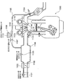
- FIG. 1 is a schematic configuration diagram showing an example of the overall configuration of an internal combustion engine (engine) to which an internal combustion engine control device according to the present invention is applied (when an exhaust gas recirculation device is provided).
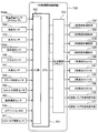
- the internal block diagram which showed an example of the internal structure of the internal combustion engine control apparatus which concerns on this invention.
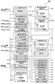
- the block diagram which showed an example of the control block of the internal combustion engine control apparatus which concerns on this invention.
- the block diagram which showed the other example of the control block of the internal combustion engine control apparatus which concerns on this invention.
- FIG. 1 shows an example of the overall configuration of an internal combustion engine (engine) to which an internal combustion engine control device that is the subject of the present invention is applied (when an exhaust gas recirculation device is provided).
- a mass flow sensor for example, an H / W sensor
- an intake throttle valve also referred to as a throttle
- an exhaust pipe of the engine 1000 which is integrated with a humidity sensor 1101 for measuring humidity during intake and an intake air temperature sensor for measuring the temperature of air in the intake pipe 1102.
- An opening degree of an EGR valve 1106 that adjusts the flow rate of exhaust gas (also referred to as EGR gas) flowing in the passage 1105 set in the middle of a passage (also referred to as EGR passage) 1105 that connects 1104 and the intake pipe 1102 is detected.
- An EGR valve opening sensor 1110, an EGR gas temperature sensor 1107 for measuring the temperature of exhaust gas in the passage 1105, and the like are provided.
- the connection position between the passage 1105 and the intake pipe 1102 that is, the exhaust gas recirculation outlet
- the humidity sensor 1101 particularly, the collector 1108 downstream of the intake throttle valve 1100.
- the exhaust gas recirculated from the exhaust pipe 1104 to the intake pipe 1102 via the passage 1105 does not reach the humidity sensor 1101.
- the engine 1000 includes a fuel injection valve 1111 that supplies (injects) fuel into the cylinder and an ignition coil 1112 that ignites the fuel supplied into the cylinder for each cylinder (for example, four cylinders).
- a fuel injection valve 1111 that supplies (injects) fuel into the cylinder
- an ignition coil 1112 that ignites the fuel supplied into the cylinder for each cylinder (for example, four cylinders).
- intake valve phase varying means 1115 and exhaust valve phase varying means 1116 for changing the phases of the intake valve 1113 and the exhaust valve 1114 provided in each cylinder are provided.
- FIG. 2 shows an example of the internal configuration of the internal combustion engine control apparatus that is the subject of the present invention.
- the internal combustion engine control apparatus 100 basically includes a CPU 151 and an output signal driver 153.
- the CPU 151 converts an electrical signal of each sensor installed in the engine into a signal for digital arithmetic processing.
- An I / O unit 152 is set, and an output signal driver 153 that converts a digital arithmetic processing control signal into an actual actuator drive signal and outputs it is connected to the CPU 151.
- the I / O unit 152 includes, for example, a mass flow sensor (for example, an H / W sensor) 154a, a humidity sensor 154, a pressure sensor 155, an intake air temperature sensor 155a, an atmospheric pressure sensor 156, a water temperature sensor 157, Electrical signals obtained from the crank angle sensor 158, the throttle valve (throttle) opening sensor 159, the oxygen concentration sensor 160, the ignition SW 150, and the EGR valve opening sensor 161 are input.
- a mass flow sensor for example, an H / W sensor
- a humidity sensor 154 for example, a humidity sensor 154, a pressure sensor 155, an intake air temperature sensor 155a, an atmospheric pressure sensor 156, a water temperature sensor 157, Electrical signals obtained from the crank angle sensor 158, the throttle valve (throttle) opening sensor 159, the oxygen concentration sensor 160, the ignition SW 150, and the EGR valve opening sensor 161 are input.
- a mass flow sensor for example, an H / W sensor
- a humidity sensor 154 for example
- the operation amount of each actuator is calculated based on the signal input to the I / O unit 152, and based on the calculation result, the fuel injection valve (here, Fuel injection valves for four cylinders) 162 to 165, ignition coils 166 to 169, intake valve phase varying means 170, exhaust valve phase varying means 171 and the like are transmitted.
- the fuel injection valve here, Fuel injection valves for four cylinders
- ignition coils 166 to 169 ignition coils 166 to 169
- intake valve phase varying means 170 intake valve phase varying means 170
- exhaust valve phase varying means 171 and the like are transmitted.
- FIG. 3 shows an example of the control block of the internal combustion engine control apparatus which is the object of the present invention and is calculated by the CPU 151 described above.
- the absolute humidity is calculated from the detected humidity detected by the humidity sensor, and the basic fuel injection amount of the fuel injected from the fuel injection valve into the cylinder is corrected based on the calculated absolute humidity. ing.
- Block 101 is a block for engine speed calculation means.
- the number of inputs per unit time of an electrical signal of the crank angle sensor set at a predetermined crank angle position of the engine, mainly a pulse signal change is counted and processed, thereby calculating the unit of the engine. Calculate the number of revolutions per hour.
- the block 130 is an estimated value of the intake pipe pressure from the output of the mass flow sensor (for example, H / W sensor), the intake air temperature sensor output, the humidity sensor output, the atmospheric pressure sensor output, and the engine speed calculated in the block 101 described above. Are used to estimate or calculate the amount of air flowing into the cylinder (cylinder) of the engine (cylinder inflow air amount) using them, and to calculate the absolute humidity.
- a block 103 is a block for calculating an engine load index representing the basic fuel and engine load required by the engine in each region from the engine speed calculated in the block 101 and the amount of air flowing into the cylinder of the engine. It is.
- the block 104 calculates the correction coefficient in each operation region of the engine of the basic fuel calculated in the block 103 from the engine speed calculated in the block 101 and the engine load calculated in the block 103. It is a block.
- a block 105 is a block for determining an optimal ignition timing in each operation region of the engine from a map search or the like based on the engine speed and the engine load.
- the block 106 is a block that performs engine transient determination from the throttle valve opening obtained from the throttle opening sensor, and calculates the acceleration / deceleration fuel correction amount and acceleration / deceleration ignition correction amount associated with the transient.
- a block 107 is a block for determining the optimum opening and closing timings of the intake and exhaust valves for the engine from the engine speed, the engine load, and the engine water temperature.
- a block 108 calculates an air-fuel ratio feedback control coefficient from an output of an oxygen concentration sensor set in the exhaust pipe of the engine so that a mixture of fuel and air supplied to the engine is maintained at a target air-fuel ratio described later. It is a block to do.
- the oxygen concentration sensor described above outputs a signal proportional to the exhaust air / fuel ratio.
- the exhaust gas has a rich side / lean side 2 relative to the stoichiometric air / fuel ratio. There is no problem even if it outputs two signals.
- Block 109 is a block for determining an optimum target air-fuel ratio in each operation region of the engine from a map search or the like based on the engine speed and the engine load.
- the target air-fuel ratio determined in this block 109 is used for the air-fuel ratio feedback control in block 108 described above.
- the block 131 is a block for correcting the basic fuel calculated in the block 103 by the basic fuel correction coefficient in the block 104, the acceleration / deceleration fuel correction amount in the block 106, the air-fuel ratio feedback control coefficient in the block 108, and the like.
- the block 111 is a block for correcting the ignition timing determined by the map search or the like in the block 105 with the acceleration / deceleration fuel correction amount or the like in the block 106 described above.
- the result obtained by applying various corrections for the decrease in the oxygen concentration due to the absolute humidity calculated in the block 130 to the basic fuel (amount) calculated in the block 103 is the fuel injection means in each cylinder.
- the basic fuel (amount) calculated in block 103 is corrected so as to increase the fuel amount, and the correction result is output to blocks 112 to 115 as fuel injection means.
- the blocks 116 to 119 are ignition means for igniting the fuel mixture flowing into the cylinder in accordance with the required ignition timing of the engine corrected in the block 111 described above.
- the blocks 120 and 121 are control means for controlling the opening / closing timings of the intake valve and the exhaust valve calculated in the block 107 described above.
- FIG. 4 shows another example of the control block of the internal combustion engine control apparatus which is the object of the present invention and is calculated by the CPU 151 described above.
- the cylinder inflow dry air amount is calculated from the detected humidity detected by the humidity sensor, and the basic fuel injection amount of the fuel injected from the fuel injection valve into the cylinder is calculated based on the calculated cylinder inflow dry air amount. It comes to calculate.
- Block 101 is a block for engine speed calculation means.
- the number of inputs per unit time of an electrical signal of the crank angle sensor set at a predetermined crank angle position of the engine, mainly a pulse signal change is counted and processed, thereby calculating the unit of the engine. Calculate the number of revolutions per hour.
- the block 102 performs drying in the intake air from the output of the mass flow sensor (for example, H / W sensor), the intake air temperature sensor output, the humidity sensor output, the atmospheric pressure sensor output, and the engine speed calculated in the block 101 described above.
- the air amount (or dry air flow rate) and water vapor amount (or water vapor flow rate) are calculated, and the dry air partial pressure and water vapor partial pressure in the intake pipe are estimated from the calculation results.
- This block estimates or calculates the amount of air (cylinder inflow dry air amount) (and the amount of water vapor) flowing into the engine cylinder (cylinder) based on the operating conditions.
- the block 103 represents the basic fuel and engine load required by the engine in each region from the engine speed calculated in the block 101 and the amount of air flowing into the engine cylinder (cylinder inflow dry air amount).
- This block calculates an engine load index.
- the block 103 sets the relative amount of dry air flowing into the cylinder so that the basic fuel (amount) required by the engine increases. If so, the basic fuel (amount) is calculated so that the basic fuel (amount) required by the engine is reduced.
- the basic fuel (amount) is calculated so that the basic fuel (amount) required by the engine increases (or decreases) as the amount of dry air flowing into the cylinder increases (or decreases). Further, in this embodiment, the block 110 of the basic fuel correction means does not have the humidity correction means shown in FIG. 3 by estimating the amount of dry air in the intake pipe.
- the dry air flow rate is estimated based on the humidity detected by the humidity sensor, and the amount of dry air and water vapor reaching the intake pipe and reaching (inflowing) into the cylinder is obtained.
- the engine can be operated with an appropriate fuel injection amount.
- FIG. 5 shows still another example of the control block of the internal combustion engine control apparatus that is the subject of the present invention, which is calculated by the above-described CPU 151 (control block of the internal combustion engine control apparatus in consideration of the EGR gas component). is there.
- the cylinder inflow dry air amount is calculated in consideration of the EGR gas component, and the fuel injection valve enters the cylinder based on the calculated cylinder inflow dry air amount.
- the basic fuel injection amount of the fuel to be injected is calculated.
- Block 101 is a block of the engine speed calculation means.
- the number of inputs per unit time of an electrical signal of the crank angle sensor set at a predetermined crank angle position of the engine, mainly a pulse signal change is counted and processed, thereby calculating the unit of the engine. Calculate the number of revolutions per hour.
- the block 132 is a block that estimates the EGR gas amount (exhaust gas recirculation amount) from the EGR valve opening sensor output in consideration of the engine operating state and calculates the EGR water vapor partial pressure.
- the block 102 performs drying in the intake air from the output of the mass flow sensor (for example, H / W sensor), the intake air temperature sensor output, the humidity sensor output, the atmospheric pressure sensor output, and the engine speed calculated in the block 101 described above. Calculate the air amount (or dry air flow rate) and water vapor amount (or water vapor flow rate), and further consider the EGR gas amount and water vapor partial pressure calculated in block 132, and the dry air partial pressure and water vapor partial pressure in the intake pipe A block for estimating or calculating the amount of air flowing into the engine cylinder (cylinder inflow) (and the amount of water vapor) based on the engine operating conditions using the estimation result It is.
- the mass flow sensor for example, H / W sensor
- the block 103 represents the basic fuel and engine load required by the engine in each region from the engine speed calculated in the block 101 and the amount of air flowing into the engine cylinder (cylinder inflow dry air amount). Calculate engine load index. For example, when the amount of EGR gas is relatively large, particularly when the EGR water vapor partial pressure is high, the block 103 is assumed to decrease the amount of dry air flowing into the cylinder relatively, so that the optimum air-fuel ratio is maintained. Therefore, the basic fuel (amount) is calculated so that the basic fuel (amount) required by the engine is reduced.
- the basic fuel (amount) is calculated so that the basic fuel (amount) required by the engine increases.
- the basic fuel (amount) required by the engine decreases (or increases) as the EGR gas volume increases (or decreases), especially when the EGR water vapor partial pressure increases (or decreases).
- the basic fuel (amount) is calculated.
- the block 110 of the basic fuel correction means does not have the humidity correction means shown in FIG. 3 by estimating the amount of dry air in the intake pipe.
- the amount of water vapor in the cylinder can be estimated by adding the amount of water vapor supplied from the EGR gas (reflux gas) to the amount of water vapor in the intake air.
- FIG. 6 shows the main part of the control block of the internal combustion engine control apparatus that is the subject of the present invention.
- the output voltage corresponding to the flow rate obtained from the mass flow sensor (for example, H / W sensor) 601 provided upstream from the intake throttle valve is filtered by the hard filter 602 and further soft filtered by the block 603. Is done.
- the output voltage value (filtering value) of the filtered intake air flow rate is converted into an air flow rate corresponding to the voltage by a table search in block 604.
- an absolute value using the intake air temperature THA that is the output value of the intake air temperature sensor, the relative humidity RH that is the output value of the humidity sensor, and the atmospheric pressure Patm that is the output value of the atmospheric pressure sensor that is input to the block 605 is absolute. Calculate humidity xvap.
- a block 606 is a block for estimating the dry air partial pressure and the water vapor partial pressure in the intake pipe using the absolute humidity xvap calculated in the block 605, and a block 607 is the estimated dry air partial pressure and the water vapor.
- This block calculates the amount of dry air flowing into the cylinder from the partial pressure, intake air temperature THA, engine speed Ne, and absolute humidity xvap.
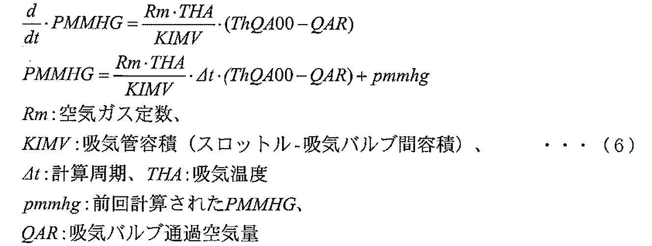
- the amount of humid air in the intake pipe is calculated by calculating the amount of wet air QwMANI from the sum of the amount of dry air ThQa entering the intake pipe and the amount of water vapor ThH2O and subtracting the amount of wet air QwAR coming out of the intake pipe. Is calculated as a pressure change by calculating the pressure. Since it is a microcomputer calculation, it is actually calculated with Z conversion.
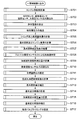
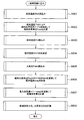
- FIG. 7 illustrates an example of the control flow of the internal combustion engine control apparatus that is the subject of the present invention.
- step S701 the engine speed is calculated.
- step S702 the outputs of a mass flow sensor (for example, H / W sensor), an intake air temperature sensor, a humidity sensor, and an atmospheric pressure sensor are read.
- step S703 the absolute humidity is calculated from the humidity detection value, the intake air temperature detection value, and the atmospheric pressure detection value.
- step S704 the pressure in the intake pipe is estimated by performing a balance calculation of the amount of dry air and the amount of water vapor calculated from the intake air amount and the absolute humidity that are detected by the mass flow sensor.
- step S705 the amount of dry air flowing into the cylinder flowing into the engine cylinder is calculated from the estimated values of the intake pipe pressure and absolute humidity.
- step S706 the basic fuel and the engine load of the engine are calculated from the engine speed and the cylinder inflow dry air amount.
- the basic fuel (amount) is calculated so that the basic fuel (amount) of the engine increases (or decreases) as the amount of dry air flowing into the cylinder increases (or decreases).
- step S707 a map search is made for the basic fuel correction coefficient of the engine based on the engine speed and the engine load.
- step S708 acceleration / deceleration determination is performed based on the output of the throttle opening sensor.
- step S709 a fuel correction amount at the time of acceleration / deceleration determination is calculated.
- step S710 the output of the oxygen concentration sensor is read.
- step S711 a target air-fuel ratio suitable for each operating region of the engine is set.
- step S712 air-fuel ratio feedback control is performed using the output of the oxygen concentration sensor and the target air-fuel ratio, and an air-fuel ratio feedback control coefficient is calculated.
- step S713 the basic fuel (amount) is corrected from the basic fuel correction coefficient, the fuel correction amount at the time of acceleration / deceleration determination, and the air-fuel ratio feedback control coefficient.
- step S714 the basic ignition timing is searched for a map from the engine speed and the engine load described above.
- step S715 an acceleration / deceleration ignition correction amount for the basic ignition timing is calculated during acceleration.
- step S716 acceleration / deceleration ignition timing correction is performed on the basic ignition timing using the acceleration / deceleration ignition correction amount.
- step S717 the opening / closing timings of the intake valve and the exhaust valve suitable for each operation region of the engine are set.
- FIG. 8 illustrates an example of the main part of the control flow of the internal combustion engine control apparatus that is the subject of the present invention.
- the calculation flow of the absolute temperature, and the dry air partial pressure and water vapor partial pressure in the intake pipe. is described in detail.
- step S801 the intake air temperature THA that is the output value of the intake air temperature sensor is read.
- step S802 the saturated water vapor pressure table is searched with the intake air temperature THA, and the saturated water vapor pressure Psat is calculated.
- step S803 the relative humidity RH, which is the output value of the humidity sensor, is read.
- step S804 the relative humidity RH / 100 is calculated.
- step S805 the atmospheric pressure Patm, which is the output value of the atmospheric pressure sensor, is read.
- step S806 the aforementioned saturated water vapor pressure Psat ⁇ the aforementioned RH / 100 / atmospheric pressure Patm is calculated, and the absolute humidity xvap is calculated.
- step S807 the amount of dry air is calculated by calculating the intake air amount ⁇ (1-xvap), which is the output value of the mass flow sensor.
- step S808 the dry air partial pressure and the water vapor partial pressure in the intake pipe are calculated using the calculation result of step S807.
- the saturated water vapor pressure Psat is obtained by a table search based on the intake air temperature THA, but may be obtained by an approximate expression based on the intake air temperature THA.
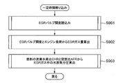
- FIG. 9 illustrates another example of the main part of the control flow of the internal combustion engine control apparatus that is the subject of the present invention, and in particular, details the estimation flow of the amount of water vapor in the EGR gas.
- step S901 the EGR valve opening that is the output value of the EGR valve opening sensor is read.
- step S902 the EGR gas amount is calculated from the EGR valve opening and engine load read in step S901.
- step S903 the water vapor partial pressure in the EGR gas (exhaust gas) is calculated from the carbon-hydrogen ratio CHR of the fuel and the air-fuel ratio AFR.
- FIG. 10 shows an example of a partial configuration of an internal combustion engine (engine) to which the internal combustion engine control apparatus to which the present invention is applied (when a supercharger is provided).
- the partial structure around the intake system is shown.
- the intake system of the engine 2000 of the illustrated embodiment mainly includes a supercharger 2101 that supercharges the amount of air sucked by the pressure of exhaust gas, and an intake throttle valve (also referred to as a throttle) that adjusts the amount of air sucked by the engine 2000.
- a supercharger 2101 that supercharges the amount of air sucked by the pressure of exhaust gas
- an intake throttle valve also referred to as a throttle
- 2102, a manifold 2103 located downstream of the throttle 2102, a fuel injection valve 2104 that supplies fuel into the cylinder, and an intake valve 2105 are provided upstream of the throttle 2102 (in the illustrated example, upstream of the throttle 2102).
- An intake sensor 2100 that measures the air amount and humidity of the intake air that the engine 2000 sucks is provided on the upstream side of the supercharger 2101 that is positioned.
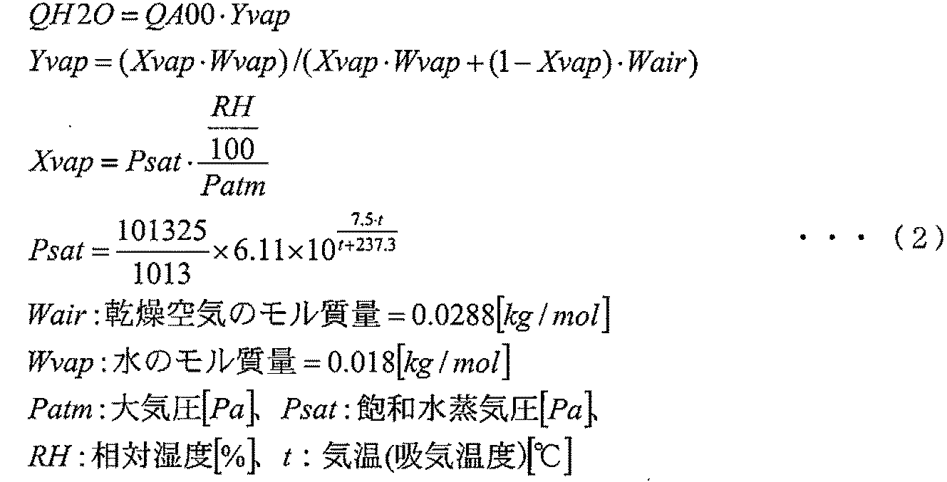
- the dry air amount (cylinder inflow dry air amount) and the water vapor amount (cylinder inflow water vapor amount) sucked by the cylinder (cylinder) of the engine 2000 are estimated or calculated. The method will be specifically described.
- Equation 2 If the relative humidity detected by the intake sensor 2100 is RH, the water vapor amount QH2O can be calculated from the intake air amount QA00 by the following equation (2). (Equation 2)
- the fuel injection amount of the fuel injection valve can be controlled appropriately and with high accuracy as described above.
- each of the above-described configurations, functions, processing units, processing means, and the like may be realized by hardware by designing a part or all of them with, for example, an integrated circuit.
- Each of the above-described configurations, functions, and the like may be realized by software by interpreting and executing a program that realizes each function by the processor.
- Information such as programs, tables, and files for realizing each function can be stored in a memory, a hard disk, a storage device such as an SSD (Solid State Drive), or a recording medium such as an IC card, an SD card, or a DVD.
- control lines and information lines indicate what is considered necessary for the explanation, and not all the control lines and information lines on the product are necessarily shown. Actually, it may be considered that almost all the components are connected to each other.
- Internal Combustion Engine Control Device 1000 Internal Combustion Engine (Engine) 1100 Inlet throttle valve (throttle) 1101 Mass flow sensor integrated humidity sensor 1102 Intake pipe 1103 Intake temperature sensor integrated pressure sensor 1104 Exhaust pipe 1105 passage (EGR passage) 1106 EGR valve 1107 EGR gas temperature sensor 1108 collector 1110 EGR valve opening sensor 1111 fuel injection valve 1112 ignition coil 1113 intake valve 1114 exhaust valve
Landscapes
- Engineering & Computer Science (AREA)
- Chemical & Material Sciences (AREA)
- Combustion & Propulsion (AREA)
- Mechanical Engineering (AREA)
- General Engineering & Computer Science (AREA)
- Analytical Chemistry (AREA)
- Signal Processing (AREA)
- Physics & Mathematics (AREA)
- Fluid Mechanics (AREA)
- Combined Controls Of Internal Combustion Engines (AREA)
- Electrical Control Of Air Or Fuel Supplied To Internal-Combustion Engine (AREA)
Abstract
Description
(例えば、H/Wセンサ)出力、吸気温センサ出力、湿度センサ出力、大気圧センサ出力、及び前述のブロック101で計算されたエンジン回転数から、吸入空気中の乾燥空気量(または、乾燥空気流量)と水蒸気量(または、水蒸気流量)を計算し、更にブロック132で算出したEGRガス量と水蒸気分圧を考慮して吸気管内の乾燥空気分圧と水蒸気分圧を推定するとともに、その推定結果を用いてエンジンの動作条件をもとに、エンジンのシリンダ(気筒)に流入する空気量(シリンダ流入乾燥空気量)(及び、水蒸気量)を推定ないし演算するブロックである。ブロック103は、前述のブロック101で計算されたエンジン回転数、及び前述のエンジンのシリンダへ流入する空気量(シリンダ流入乾燥空気量)から、各領域におけるエンジンの要求する基本燃料及びエンジン負荷を表すエンジン負荷指標を計算する。ブロック103は、例えば、EGRガス量が相対的に大きい場合、特にそのうちのEGR水蒸気分圧が高い場合、シリンダ流入乾燥空気量は相対的に減少すると推定されるので、最適な空燃比を維持するために、エンジンの要求する基本燃料(量)が少なくなるように当該基本燃料(量)を算出する。一方で、EGRガス量が相対的に小さい場合、特にそのうちのEGR水蒸気分圧が低い場合、シリンダ流入乾燥空気量は相対的に増加すると推定されるので、最適な空燃比を維持するために、エンジンの要求する基本燃料(量)が多くなるように当該基本燃料(量)を算出する。すなわち、EGRガス量の増加(あるいは、減少)、特にそのうちのEGR水蒸気分圧の増加(あるいは、減少)に応じて、エンジンの要求する基本燃料(量)が少なくなる(あるいは、多くなる)ように、当該基本燃料(量)を算出する。また、本実施例においては、図4と同様、吸気管内の乾燥空気量を推定することで、基本燃料補正手段のブロック110に、図3に示した湿度補正手段を持たない構成としている。
(数1)

(数2)
(数3)

(数4)

(数5)

(数6)
(数7)
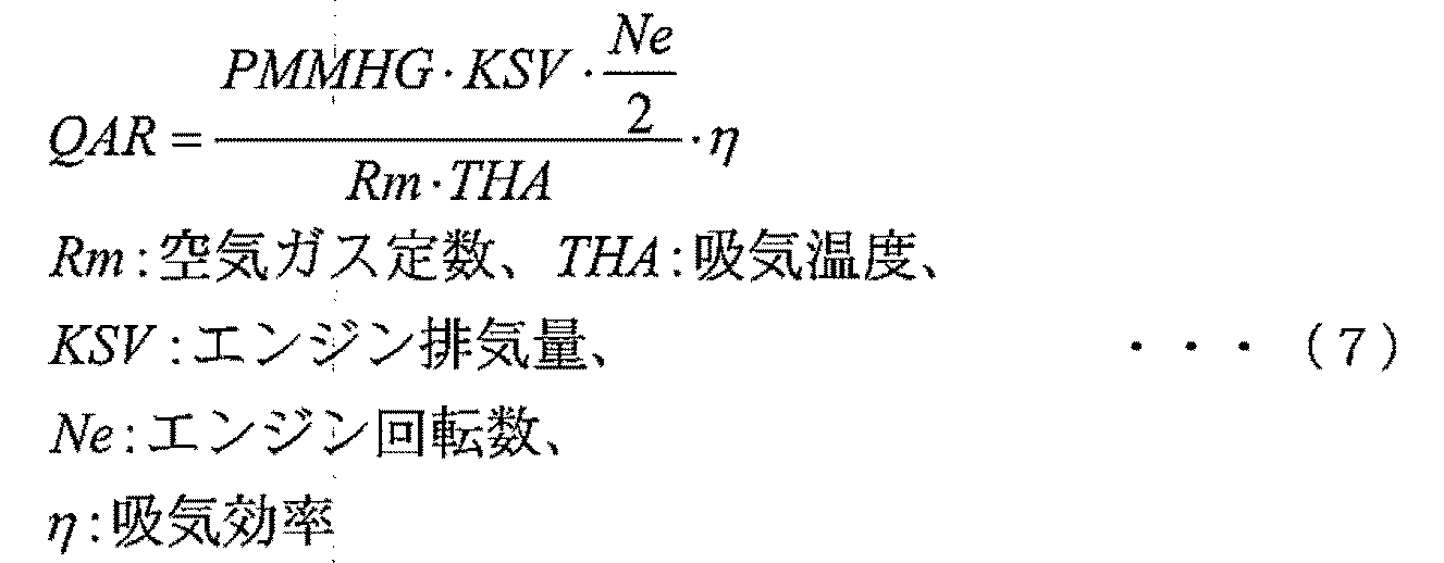
(数8)
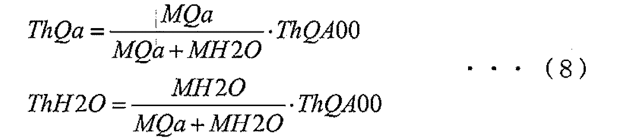
(数9)
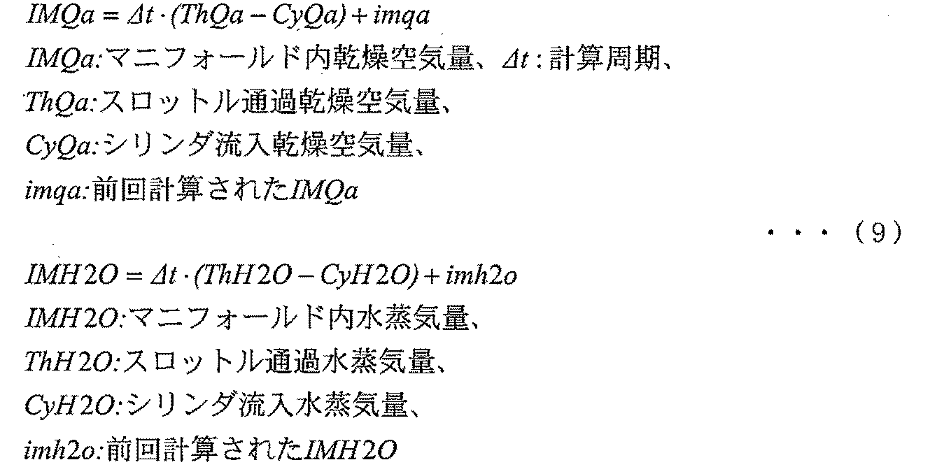
(数10)

1000 内燃機関(エンジン)
1100 吸気絞り弁(スロットル)
1101 質量流量センサ一体湿度センサ
1102 吸気管
1103 吸気温センサ一体圧力センサ
1104 排気管
1105 通路(EGR通路)
1106 EGRバルブ
1107 EGRガス温センサ
1108 コレクタ
1110 EGRバルブ開度センサ
1111 燃料噴射弁
1112 点火コイル
1113 吸気バルブ
1114 排気バルブ
Claims (14)
- 吸気管内に配備された吸気絞り弁より上流側の湿度を検出する湿度センサにより検出される検出湿度に基づいて、燃料噴射弁から気筒内に噴射される燃料の燃料噴射量を制御する内燃機関制御装置であって、
前記湿度センサにより検出される検出湿度に基づいて算出もしくは推定される乾燥空気流量に応じて、前記燃料噴射弁の燃料噴射量を算出または補正することを特徴とする内燃機関制御装置。 - 請求項1に記載の内燃機関制御装置において、
前記湿度センサにより検出される検出湿度に基づいて前記湿度センサより下流に位置する内燃機関の気筒内に流入する空気の乾燥空気流量を推定し、推定した乾燥空気流量に応じて、前記燃料噴射弁の燃料噴射量を算出または補正することを特徴とする内燃機関制御装置。 - 請求項1に記載の内燃機関制御装置において、
前記吸気絞り弁より上流側の空気量を検出する質量流量センサにより検出される検出空気量に基づいて、前記燃料噴射弁の燃料噴射量を算出または補正することを特徴とする内燃機関制御装置。 - 請求項3に記載の内燃機関制御装置において、
排気ガスの還流吹き出し口が、前記質量流量センサ及び前記湿度センサより下流に位置していることを特徴とする内燃機関制御装置。 - 請求項4に記載の内燃機関制御装置において、
前記質量流量センサから得られる空気流量と前記湿度センサから検出される検出湿度から水蒸気流量と乾燥空気流量を求めることを特徴とする内燃機関制御装置。 - 請求項5に記載の内燃機関制御装置において、
前記水蒸気流量と乾燥空気流量に基づいて、前記吸気管内の乾燥空気と水蒸気の流量を推定することを特徴とする内燃機関制御装置。 - 請求項6に記載の内燃機関制御装置において、
前記吸気管内の乾燥空気と水蒸気の流量の推定結果に基づいて、内燃機関の気筒が吸入する乾燥空気量と水蒸気量を推定することを特徴とする内燃機関制御装置。 - 請求項7に記載の内燃機関制御装置において、
前記湿度センサより下流に流入する水蒸気量を排気ガス還流量から推定することを特徴とする内燃機関制御装置。 - 請求項8に記載の内燃機関制御装置において、
前記排気ガス還流量に対し、燃料の組成及び吸気中の水蒸気量を考慮して前記水蒸気量を推定することを特徴とする内燃機関制御装置。 - 請求項7に記載の内燃機関制御装置において、
前記湿度センサより下流に流入する水蒸気量と水蒸気以外の成分の流量を排気ガス還流量から推定することを特徴とする内燃機関制御装置。 - 請求項10に記載の内燃機関制御装置において、
前記排気ガス還流量に対し、燃料の組成及び吸気中の水蒸気量を考慮して前記水蒸気以外の成分の流量を推定することを特徴とする内燃機関制御装置。 - 請求項1に記載の内燃機関制御装置において、
前記乾燥空気流量の増加或いは減少に応じて、前記燃料噴射弁の燃料噴射量が多くなる或いは少なくなるように、前記燃料噴射弁の燃料噴射量を算出または補正することを特徴とする内燃機関制御装置。 - 請求項1に記載の内燃機関制御装置において、
前記吸気管に還流される排気ガス還流量の増加或いは減少に応じて、前記燃料噴射弁の燃料噴射量が少なくなる或いは多くなるように、前記燃料噴射弁の燃料噴射量を算出または補正することを特徴とする内燃機関制御装置。 - 請求項1に記載の内燃機関制御装置において、
前記吸気管に還流される排気ガスの水蒸気分圧の増加或いは減少に応じて、前記燃料噴射弁の燃料噴射量が少なくなる或いは多くなるように、前記燃料噴射弁の燃料噴射量を算出または補正することを特徴とする内燃機関制御装置。
Priority Applications (4)
| Application Number | Priority Date | Filing Date | Title |
|---|---|---|---|
| JP2017563708A JP6609642B2 (ja) | 2016-01-27 | 2016-11-16 | 内燃機関制御装置 |
| DE112016005150.6T DE112016005150T5 (de) | 2016-01-27 | 2016-11-16 | Steuervorrichtung für einen Verbrennungsmotor |
| US16/066,807 US10677183B2 (en) | 2016-01-27 | 2016-11-16 | Internal combustion engine control apparatus |
| CN201680079457.3A CN108699980B (zh) | 2016-01-27 | 2016-11-16 | 内燃机控制装置 |
Applications Claiming Priority (2)
| Application Number | Priority Date | Filing Date | Title |
|---|---|---|---|
| JP2016013725 | 2016-01-27 | ||
| JP2016-013725 | 2016-01-27 |
Publications (1)
| Publication Number | Publication Date |
|---|---|
| WO2017130527A1 true WO2017130527A1 (ja) | 2017-08-03 |
Family
ID=59397613
Family Applications (1)
| Application Number | Title | Priority Date | Filing Date |
|---|---|---|---|
| PCT/JP2016/083877 Ceased WO2017130527A1 (ja) | 2016-01-27 | 2016-11-16 | 内燃機関制御装置 |
Country Status (5)
| Country | Link |
|---|---|
| US (1) | US10677183B2 (ja) |
| JP (1) | JP6609642B2 (ja) |
| CN (1) | CN108699980B (ja) |
| DE (1) | DE112016005150T5 (ja) |
| WO (1) | WO2017130527A1 (ja) |
Cited By (1)
| Publication number | Priority date | Publication date | Assignee | Title |
|---|---|---|---|---|
| CN109184932A (zh) * | 2018-08-06 | 2019-01-11 | 天津内燃机研究所(天津摩托车技术中心) | 高速汽油发动机瞬态工况空燃比的控制方法 |
Families Citing this family (2)
| Publication number | Priority date | Publication date | Assignee | Title |
|---|---|---|---|---|
| CN116398309A (zh) * | 2023-06-06 | 2023-07-07 | 江铃汽车股份有限公司 | 基于进气湿度的天然气发动机控制方法、系统及车辆 |
| WO2025096691A1 (en) * | 2023-10-31 | 2025-05-08 | Cummins Inc. | Systems and methods for estimating hydrogen in an exhaust gas stream |
Citations (8)
| Publication number | Priority date | Publication date | Assignee | Title |
|---|---|---|---|---|
| JPH02256850A (ja) * | 1989-03-28 | 1990-10-17 | Mitsubishi Electric Corp | 内燃機関の燃料制御装置 |
| JPH08135519A (ja) * | 1994-11-14 | 1996-05-28 | Sekiyu Sangyo Kasseika Center | エンジンの排気ガス還流装置の制御方法及び制御装置 |
| JPH09304322A (ja) * | 1996-05-15 | 1997-11-28 | Hitachi Ltd | 湿度検出器およびそれを用いたエンジン制御装置 |
| JP2000328999A (ja) * | 1999-05-21 | 2000-11-28 | Horiba Ltd | 走行車両における軸平均有効圧簡易測定方法 |
| JP2003222050A (ja) * | 2002-01-30 | 2003-08-08 | Yamaha Motor Co Ltd | エンジンの駆動制御方法 |
| JP2008286019A (ja) * | 2007-05-15 | 2008-11-27 | Isuzu Motors Ltd | エンジン |
| JP2009024685A (ja) * | 2007-07-24 | 2009-02-05 | Toyota Motor Corp | 内燃機関の制御装置 |
| JP2012246792A (ja) * | 2011-05-25 | 2012-12-13 | Toyota Motor Corp | 排気再循環制御装置および内燃機関の排気再循環システム |
Family Cites Families (8)
| Publication number | Priority date | Publication date | Assignee | Title |
|---|---|---|---|---|
| JPH0670385B2 (ja) | 1986-03-03 | 1994-09-07 | トヨタ自動車株式会社 | 内燃機関の制御装置 |
| US4971009A (en) | 1989-03-10 | 1990-11-20 | Mitsubishi Denki Kabushiki Kaisha | Fuel control apparatus for internal combustion engine |
| JP4264979B2 (ja) | 2004-05-21 | 2009-05-20 | 株式会社デンソー | データ処理装置 |
| JP5171740B2 (ja) | 2009-06-17 | 2013-03-27 | 本田技研工業株式会社 | 内燃機関の制御装置 |
| JP5831295B2 (ja) | 2012-03-01 | 2015-12-09 | 株式会社デンソー | エンジン制御装置 |
| JP6141746B2 (ja) | 2013-10-16 | 2017-06-07 | 日立オートモティブシステムズ株式会社 | 内燃機関の制御装置 |
| JP6143910B1 (ja) * | 2016-03-30 | 2017-06-07 | 三菱電機株式会社 | 内燃機関の制御装置及びその制御方法 |
| JP6734221B2 (ja) * | 2017-04-28 | 2020-08-05 | トヨタ自動車株式会社 | 内燃機関の制御装置 |
-
2016
- 2016-11-16 CN CN201680079457.3A patent/CN108699980B/zh active Active
- 2016-11-16 WO PCT/JP2016/083877 patent/WO2017130527A1/ja not_active Ceased
- 2016-11-16 US US16/066,807 patent/US10677183B2/en active Active
- 2016-11-16 DE DE112016005150.6T patent/DE112016005150T5/de active Pending
- 2016-11-16 JP JP2017563708A patent/JP6609642B2/ja active Active
Patent Citations (8)
| Publication number | Priority date | Publication date | Assignee | Title |
|---|---|---|---|---|
| JPH02256850A (ja) * | 1989-03-28 | 1990-10-17 | Mitsubishi Electric Corp | 内燃機関の燃料制御装置 |
| JPH08135519A (ja) * | 1994-11-14 | 1996-05-28 | Sekiyu Sangyo Kasseika Center | エンジンの排気ガス還流装置の制御方法及び制御装置 |
| JPH09304322A (ja) * | 1996-05-15 | 1997-11-28 | Hitachi Ltd | 湿度検出器およびそれを用いたエンジン制御装置 |
| JP2000328999A (ja) * | 1999-05-21 | 2000-11-28 | Horiba Ltd | 走行車両における軸平均有効圧簡易測定方法 |
| JP2003222050A (ja) * | 2002-01-30 | 2003-08-08 | Yamaha Motor Co Ltd | エンジンの駆動制御方法 |
| JP2008286019A (ja) * | 2007-05-15 | 2008-11-27 | Isuzu Motors Ltd | エンジン |
| JP2009024685A (ja) * | 2007-07-24 | 2009-02-05 | Toyota Motor Corp | 内燃機関の制御装置 |
| JP2012246792A (ja) * | 2011-05-25 | 2012-12-13 | Toyota Motor Corp | 排気再循環制御装置および内燃機関の排気再循環システム |
Cited By (1)
| Publication number | Priority date | Publication date | Assignee | Title |
|---|---|---|---|---|
| CN109184932A (zh) * | 2018-08-06 | 2019-01-11 | 天津内燃机研究所(天津摩托车技术中心) | 高速汽油发动机瞬态工况空燃比的控制方法 |
Also Published As
| Publication number | Publication date |
|---|---|
| CN108699980B (zh) | 2021-06-18 |
| US20190024600A1 (en) | 2019-01-24 |
| US10677183B2 (en) | 2020-06-09 |
| DE112016005150T5 (de) | 2018-08-02 |
| JPWO2017130527A1 (ja) | 2018-09-27 |
| CN108699980A (zh) | 2018-10-23 |
| JP6609642B2 (ja) | 2019-11-20 |
Similar Documents
| Publication | Publication Date | Title |
|---|---|---|
| CN104061091B (zh) | 内燃机的控制装置 | |
| CN103967636B (zh) | 外部egr速率反馈 | |
| JP6707038B2 (ja) | 内燃機関の制御装置 | |
| CN107269402B (zh) | 内燃机的控制装置及其控制方法 | |
| CN106567784B (zh) | 内燃机的控制装置及内燃机的控制方法 | |
| JP5360307B2 (ja) | 内燃機関の制御装置 | |
| CN106545431B (zh) | 发动机控制装置 | |
| KR100284376B1 (ko) | 내연기관의 배기재순환 제어장치 | |
| JP6609642B2 (ja) | 内燃機関制御装置 | |
| US10344697B2 (en) | Control apparatus for internal combustion engine | |
| JP5088429B2 (ja) | 内燃機関の制御装置 | |
| JP6544365B2 (ja) | 絶対湿度センサ | |
| JP6545290B2 (ja) | 制御装置 | |
| JP2008286019A (ja) | エンジン | |
| JP6451705B2 (ja) | 内燃機関の制御装置 | |
| JP4072860B2 (ja) | 内燃機関の吸入空気量検出装置 | |
| JP2015083778A (ja) | 内燃機関の制御装置 | |
| WO2018159316A1 (ja) | 流量測定システム | |
| JP2013253564A (ja) | 動力システムの制御装置 | |
| JP6094743B2 (ja) | エンジンの制御装置 | |
| JP2008286122A (ja) | 空燃比を検出する装置 | |
| JP5381779B2 (ja) | 内燃機関の制御装置 | |
| JP6679917B2 (ja) | 内燃機関のNOx濃度制御システム、内燃機関、及び内燃機関のNOx濃度制御方法 | |
| JP6312566B2 (ja) | 内燃機関の失火判定装置 | |
| JP2013155614A (ja) | 過給エンジンの制御装置 |
Legal Events
| Date | Code | Title | Description |
|---|---|---|---|
| 121 | Ep: the epo has been informed by wipo that ep was designated in this application |
Ref document number: 16888112 Country of ref document: EP Kind code of ref document: A1 |
|
| WWE | Wipo information: entry into national phase |
Ref document number: 112016005150 Country of ref document: DE |
|
| ENP | Entry into the national phase |
Ref document number: 2017563708 Country of ref document: JP Kind code of ref document: A |
|
| 122 | Ep: pct application non-entry in european phase |
Ref document number: 16888112 Country of ref document: EP Kind code of ref document: A1 |